t13/1484d revision 3 working t13 draft...
TRANSCRIPT

T13/1484D Revision 3
Working T13
Draft D1484
Revision 3
February 21, 2002
Information Technology - BIOS Enhanced Disk Drive Services – 2 (EDD-2)
This is an internal working document of T13, a Technical Committee of Accredited Standards Committee NCITS. As such, this is not a completed standard and has not been approved. The T13 Technical Committee may modify the contents. The contents are actively being modified by T13. This document is made available for review and comment only.
Permission is granted to members of NCITS, its technical committees, and their associated task groups to reproduce this document for the purposes of NCITS standardization activities without further permission, provided this notice is included. All other rights are reserved. Any commercial or for-profit replication or republication is prohibited.
T13 Technical Editor:
Curtis E. Stevens
Pacific Digital Corp.
2052 Alton Pkwy
Irvine, Ca. 92606
USA
Tel: (949) 477-5713
Fax: (949) 252-9397
Email: [email protected]
Reference number
ANSI NCITS.*** - 200x
Printed February, 21, 2002 5:18PM
T13/1484D Revision 3
Other Points of Contact:
T13 Chair T13 Vice-Chair
Pete McLean Dan Colegrove
Maxtor Corporation IBM Corporation
2190 Miller Drive 2903 Carmelo Drive
Longmont, CO 80501 Henderson, NV 89052
Tel: 303-678-2149 Tel: 702 614-6119
Fax: 303-682-4811 Fax:
NCITS Secretariat
Administrator Standards Processing
1250 Eye Street, NW Suite 200
Washington, DC 20005
Tel: 202-737-8888
Fax: 202-638-4922
Email: [email protected]
T13 Reflector
See the T13 WEB site for reflector information.
T13 WEB site
www.t13.org
T13 mailings
Global Engineering
15 Inverness Way East
Englewood, CO 80112-5704
Tel: 303-792-2181 or 800-854-7179
Fax: 303-792-2192
T13/1484D Revision 3
DOCUMENT STATUS
Revision 0 – June 21, 1999 Initial revision, document created from ANSI NCITS 347
Revision 1 – October 23, 2001 Incorporated E01127r0.doc Incorporated E01125r0.doc
Revision 1a – December 10, 2001 Incorporated editorial changes from T13 meeting Revision 2 – December 11, 2001 Accepted change bars to create a letter ballot document Revision 2a – February 18, 2002 Incorporated letter ballot feedback and meeting comments Revision 3 – February 21, 2002 Updated to Rev 3 and accepted change bars for forwarding to ANSI

T13/1484D Revision 3
ANSI®
NCITS.****-200x
American National Standard
For Information Systems -
BIOS Enhanced Disk Drive Services – 2
Secretariat
Information Technology Industry Council
Approved mm dd yy
American National Standards Institute, Inc.
Abstract
This standard describes services currently in use on IA-32 and IA-64 architecture personal computer systems. These services are provided by BIOS firmware to support hard disks up to 16 mega-terabytes (16x1018 bytes). This standard also provides BIOS level services for determining the relationship between BIOS device numbers and the physical mass storage devices attached to the personal computer. The services defined in this standard can be applied to mass storage devices with ATA, ATAPI, SCSI, USB, Fibre Channel, 1394, I2O, and other interfaces.

T13/1484D Revision 3
American
National Standard
Approval of an American National Standard requires verification by ANSI that the requirements for due process, consensus, and other criteria for approval have been met by the standards developer. Consensus is established when, in the judgment of the ANSI Board of Standards Review, substantial agreement has been reached by directly and materially affected interests. Substantial agreement means much more than a simple majority, but not necessarily unanimity. Consensus requires that all views and objections be considered, and that effort be made towards their resolution.
The use of American National Standards is completely voluntary; their existence does not in any respect preclude anyone, whether he has approved the standards or not, from manufacturing, marketing, purchasing, or using products, processes, or procedures not conforming to the standards.
The American National Standards Institute does not develop standards and will in no circumstances give interpretation on any American National Standard. Moreover, no person shall have the right or authority to issue an interpretation of an American National Standard in the name of the American National Standards Institute. Requests for interpretations should be addressed to the secretariat or sponsor whose name appears on the title page of this standard.
CAUTION NOTICE: This American National Standard may be revised or withdrawn at any time. The procedures of the American National Standards Institute require that action be taken periodically to reaffirm, revise, or withdraw this standard. Purchasers of American National Standards may receive current information on all standards by calling or writing the American National Standards Institute.
CAUTION: The developers of this standard have requested that holders of patents that may be required for the implementation of the standard, disclose such patents to the publisher. However, neither the developers nor the publisher have undertaken a patent search in order to identify which, if any, patents may apply to this standard.
As of the date of publication of this standard and following calls for the identification of patents that may be required for the implementation of the standard, no such claims have been made.
The developer or the publisher in respect to any standard it processes conducts no further patent search. No representation is made or implied that licenses are not required to avoid infringement in the use of this standard.
Published by
American National Standards Institute
11 West 42nd Street, New York, New York 10036
Copyright 2nnn by American National Standards Institute
All rights reserved.


T13/1484D Revision 3
Page i
Contents Page Introduction ....................................................................................................................................... iii 1 Scope..........................................................................................................................................1 2 Normative References..................................................................................................................1
2.1 Approved References ............................................................................................................2 2.2 References Under Development.............................................................................................2 2.3 Other References..................................................................................................................2
3 Keywords, Definitions, Abbreviations, and Conventions..................................................................3 3.1 Keywords..............................................................................................................................3 3.2 Definitions and Abbreviations.................................................................................................3 3.3 Conventions..........................................................................................................................6
4 Overview.....................................................................................................................................7 5 INT 13h Calling Conventions.........................................................................................................8
5.1 Data Structure.......................................................................................................................8 5.2 Removable Media .................................................................................................................9 5.3 INT 13h Interface Subsets ...................................................................................................10
6 INT 13h Function Definitions .......................................................................................................10 6.1 Check Extensions Present ...................................................................................................11 6.2 Extended Read ...................................................................................................................11 6.3 Extended Write ...................................................................................................................12 6.4 Verify Sectors .....................................................................................................................12 6.5 Lock/Unlock Media..............................................................................................................12 6.6 Eject Removable Media.......................................................................................................13 6.7 Extended Seek....................................................................................................................13 6.8 Get Device Parameters........................................................................................................13 6.9 Get Extended Media Change Status.....................................................................................21 6.10 Set Hardware Configuration..............................................................................................22 6.11 Send Packet Command....................................................................................................23
7 INT 15h Removable Media Eject .................................................................................................25 Table Page Table 1 - Device Address Packet .........................................................................................................9 Table 2 - Check Extensions Present Buffer.........................................................................................11 Table 3 - Result Buffer ......................................................................................................................14 Table 4 - Interface Path Definitions ....................................................................................................16 Table 5 - Device Path Definitions.......................................................................................................17 Table 6 - Device parameter table extension........................................................................................18 Table 7 - Translation Type.................................................................................................................20 Table 8 - Hardware Configuration Sub-Functions ................................................................................22 Table 9 - Formatted Command Packet ...............................................................................................23 Table 10 - Formatted Protocol Specific Data.......................................................................................24 Table 11 – Output Parameters...........................................................................................................25
Figure Page Figure 1 - System Component Diagram................................................................................................8

T13/1484D Revision 3
Foreword
(This foreword is not part of American National Standard NCITS.xxx-200x)
In the past, DOS has accessed its mass storage devices using an INT13 programming interface provided by BIOS firmware to higher-level software. This interface was designed in the early 1980’s and upgraded in the late 1980’s. The maximum theoretical capacity of this API is slightly more than 8.4 gigabytes. The INT 13h interface, now known as the legacy INT 13h interface, uses function numbers 01h through 15h and is Cylinder-Head-Sector (CHS) oriented. An extended INT 13h interface has been created, the purpose of these INT 13h extensions is to:
Replace CHS addressing with Logical Block Addressing (LBA).
Remove the current requirement of using interrupt 41h/46h to point at the Fixed Disk Parameter Table information.
Give the BIOS better control over how this data shall be used.
Make location and configuration information available to operating systems that do not use the BIOS to access mass storage devices.
Use data structures that apply to both IA-32 and IA-64 architecture systems.
Use data structures that can address media capacities for the next 20 years.
Requests for interpretation, suggestions for improvement and addenda, or defect reports are welcome. They should be sent to the NCITS Secretariat, Information Technology Industry Council, 1250 I Street NW, Suite 200, Washington, DC 20005-3922.
This standard was processed and approved for submittal to ANSI by National Committee for Information Technology Standardization (NCITS). Committee approval of this standard does not necessarily imply that all committee members voted for approval. At the time it approved this standard, NCITS had the following members:
[NCITS membership goes here]
Technical Committee T13 on ATA Interfaces, that reviewed this standard, had the following members:
[T13 membership goes here]

T13/1484D Revision 3
Page iii
Introduction
This standard encompasses the following:
Clause 1 describes the scope.
Clause 2 provides normative references.
Clause 3 provides definitions, abbreviations, and conventions.
Clause 4 is the overview.
Clause 5 is the INT 13h Calling Conventions.
Clause 6 is the INT 13h Function Definitions.
Clause 7 describes INT 15h removable media eject.

T13/1484D Revision 3
Page 1
AMERICAN NATIONAL STANDARD NCITS.***-200x
American National Standard for Information Systems -
Information Technology - BIOS Enhanced Disk Drive Services – 2 (EDD-2)
1 Scope
This standard assumes that the reader is familiar with the conventional INT 13h interface, the usage of the BIOS Device Parameter Table, and the basic operation of mass storage devices. This standard describes in detail BIOS functions and data structures that are used as an abstraction layer to allow higher-level applications to access mass storage devices in an interface and command-set independent manner. To comply with this standard, higher-level software shall call the INT functions using the data structures described herein, and system firmware shall provide the INT functions and data structures described herein.
The storage industry has increased the capacity and functionality of many types of mass storage devices. This increase in capacity and functionality has required the development of a BIOS interface. This standard documents the BIOS interface that is supplied by many BIOS vendors. This standard defines solutions to the following INT 13h BIOS-specific issues:
The INT 13h interface has a limit of 528 megabytes (MB);
The INT 13h interface allows more than two devices to be attached to a system but has no consistent method for storing the additional configuration parameters;
The INT 13h interface does not define CHS-independent methods for addressing devices. The methods defined by the INT 13h interface are not device-geometry independent. A different method of address representation and operation is needed;
Methods of data transfer continue to be added to ATA devices. Capabilities such as, DMA modes, multi-sector data transfers and Fast PIO are not reported to the operating system via the INT 13h interface;
Systems require more than two storage devices, and with this requirement comes the requirement to assign the order in which the devices are to be accessed. The INT 13 interface does not provide this capability;
The INT 13h interface does not make location and configuration information available to operating systems that do not use the BIOS to access mass storage devices;
The INT 13h interface does not provide a linkage between the BIOS device assignments on the operating system device letter assignments;
The INT 13h interface does not use data structures that apply to both IA-32 and IA-64 architecture systems.
2 Normative References
The following standards contain provisions that, through reference in the text, constitute provisions of this standard. Many of these standards are referenced because they contain the information necessary for describing a method of accessing a device on the specified interface. At the time of publication, the editions indicated were

T13/1484D Revision 3
Page 2
valid. All standards are subject to revision, and parties to agreements based on this standard are encouraged to investigate the possibility of applying the most recent editions of the standards listed below.
Copies of the following documents can be obtained from ANSI: Approved ANSI standards, approved and draft international and regional standards (ISO, IEC, CEN/CENELEC, ITUT), and approved and draft foreign standards (including BSI, JIS, and DIN). For further information, contact ANSI Customer Service Department at 212-642-4900 (phone), 212-302-1286 (fax) or via the World Wide Web at http://www.ansi.org.
Additional availability contact information is provided below as needed.
2.1 Approved References
The following approved ANSI standards and technical reports, approved international and regional standards and technical reports (ISO, IEC, CEN/CENELEC, ITUT), may be obtained from the international and regional organizations who control them.
NCITS 340-2000 AT Attachment with Packet Interface (ATA/ATAPI-5)
NCITS 325-1998 Serial Bus Protocol – 2 (SBP-2)
NCITS 333-1999 Multi-Media Commands - 2 (MMC-2)
BSR NCITS 330 Reduced Block Commands (RBC)
ANSI/IEEE 394:1995 Extended Unique Identifier, 64-bit (EUI-64)
IEEE 1394-1995 IEEE Standard for a High Performance Serial Bus
IEEE 1394a-2000 IEEE Standard for a High Performance Serial Bus – Amendment 1
X3.303 Fibre Channel Physical and Signaling Interface-3
X3.301-1997 SCSI - 3 SPC
2.2 References Under Development
At the time of publication, the following referenced standards were still under development. For information on the current status of the document, or regarding availability, contact the relevant standards body or other organization as indicated.
NCITS 1410D AT Attachment with Packet Interface (ATA/ATAPI-6)
NCITS 1236D SCSI Primary Commands - 2 (SPC-2)
NCITS 1363D Multi-Media Commands - 3 (MMC-3)
IEEE P1394b Standard for High Performance Serial Bus (High Speed Supplement)
For more information on the current status of the above documents, contact NCITS. To obtain copies of these documents, contact Global Engineering or NCITS.
2.3 Other References
The following standards and specifications were also referenced.
NCITS TR-21 BIOS Enhanced Disk Drive Technical Report
BIOS Boot Specification (Compaq, Phoenix and Intel), www.phoenix.com/techs/specs.html
El Torito CD-ROM Boot Specification, www.phoenix.com/techs/specs.html
ATAPI Removable Media BIOS Specification, www.phoenix.com/techs/specs.html
Universal Serial Bus Revision 1.1, www.usb.org/developers
Mass Storage Overview, www.usb.org/developers
I2O Software Specification v2.0, www.i2osig.org
T13/1484D Revision 3
Page 3
3 Keywords, Definitions, Abbreviations, and Conventions
3.1 Keywords
Several keywords are used to differentiate between different levels of requirements and optionality.
3.1.1 Mandatory
A keyword indicating items to be implemented as defined by this standard.
3.1.2 May
A keyword that indicates flexibility of choice with no implied preference.
3.1.3 Optional
A keyword that describes features that are not required by this standard. However, if any optional feature defined by the standard is implemented, it shall be done in the way defined by the standard. Describing a feature as optional in the text is done to assist the reader.
3.1.4 Reserved
A keyword indicating reserved bits, bytes, words, fields, and code values that are set aside for future standardization. Their use and interpretation may be specified by future extensions to this or other standards. A reserved bit, byte, word, or field shall be set to zero, or in accordance with a future extension to this standard. The recipient shall not check reserved bits, bytes, words, or fields. Receipt of reserved code values in defined fields shall be treated as an error.
3.1.5 Shall
A keyword indicating a mandatory requirement. Designers are required to implement all such mandatory requirements to ensure interoperability with other standard conformant products.
3.1.6 Should
A keyword indicating flexibility of choice with a strongly preferred alternative. Equivalent to the phrase “it is recommended”.
3.2 Definitions and Abbreviations
For the purposes of this standard, the following definitions apply:
3.2.1 ATA
An AT Attachment (also known as IDE), is a storage interface that conforms to an ATA standard.
3.2.2 BDA
The BIOS Data Area is an area of reserved memory used by the BIOS and O/S to store data about the system hardware. It is located at memory segment 40h starting with 40h:00h.
3.2.3 BIOS
The Basic Input/Output System is the firmware embedded on a chip located on the computer’s main board. The BIOS executes POST to test and initialize the system components and then loads the O/S. The BIOS also handles the low-level Input/Output to the various peripheral devices connected to the computer.

T13/1484D Revision 3
Page 4
3.2.4 Byte
A byte is a unit of data that consists of eight bits as described below:
Bit 7 Bit 6 Bit 5 Bit 4 Bit 3 Bit 2 Bit 1 Bit 0
3.2.5 CF
The Carry Flag is a bit in the Flags Register in the microprocessor.
3.2.6 CHS
CHS addressing is a method of addressing the contents of a storage device using logical cylinders (C), logical heads (H), and logical sectors (S). This method of addressing allows a maximum C=16,383, H=16, S=63, resulting in a maximum device capacity of 8.4 gigabytes (16,383 ? 16 ? 63 ? 512 bytes per sector ? 8.4 gigabytes). . See LBA addressing for another addressing method.
3.2.7 Conventional and enhanced
When a word, term, or phrase is modified by the word “conventional” it refers to the legacy style, or method of operation that is limited to addressing ATA devices that have a 528 MB capacity or less. When a word, term, or phrase is modified by the word “enhanced” it means there is a “conventional” and an “enhanced” method of operation. The “enhanced” method is defined by this standard.
3.2.8 DOS
DOS is a disk operating system that uses the system BIOS as a firmware abstraction layer to access system hardware. Examples of DOS based operating systems include MS-DOS®, DR-DOS®, PC-DOS®, Free DOS, Windows® 3.11, and Windows® 95.
3.2.9 DWord
A DWord (Double Word) is a unit of data that consist of four bytes. This data may be represented on paper as a series of bits numbered from 31 to 0. In memory byte 0 of a DWord is stored in the lowest byte address and Byte 3 is stored in the highest byte address.
On Paper:
Bit 31 Bit 0
Byte 3 Byte 2 Byte 1 Byte 0 In Memory:
Bit 7 Bit 0 Bit 31 Bit 24
Byte 0 Byte 1 Byte 2 Byte 3
3.2.10 Host
The Host is the PC that is controlled by the BIOS.
3.2.11 IA-32
IA-32 refers to the Intel Architecture 32-bit wide processor data bus.
3.2.12 IA-64
IA-64 refers to the Intel Architecture 64-bit wide processor data bus.

T13/1484D Revision 3
Page 5
3.2.13 INT 13h
A BIOS interrupt service that provides a protocol independent method for addressing floppy, hard drive, and other storage devices.
3.2.14 INT 40h
INT 40h is a BIOS interrupt service that provides a protocol independent method for addressing INT 13h devices that have a device number less than or equal to 7Fh.
3.2.15 IPL Device
An Initial Program Load Device is any device in the system that may boot and load an O/S. In standard AT machines, this is normally the floppy drive or hard drive.
3.2.16 LBA
LBA is a method of addressing a device that involves using a Logical Block Address. For example, this method of addressing allows a maximum sector address of 228-1, or 137.4 GB of data on an ATA device using 28-bit addressing. See CHS for another address method.
3.2.17 Logical Address/Geometry
A logical address or geometry is used to address a device by an application, such as DOS, using the INT 13h interface. INT 13h Fn 8 returns the logical geometry of the device.
3.2.18 NV Memory
Non-Volatile memory is memory that retains content even when the power has been removed. The most common type of NV memory on a PC is the CMOS RAM that is used to store system configuration information.
3.2.19 O/S
An Operating System is a software abstraction layer that provides services that give applications access to system hardware, in a hardware independent fashion. Examples of these services include memory management, multi-threaded task management, file system management, printer management, and screen management.
3.2.20 POST
The Power-On Self-Test is the part of the BIOS that takes control immediately after power is applied to the computer. POST initializes the computer hardware so that an O/S may be loaded.
3.2.21 Protected Mode
Intel x86 processors have several modes of main memory addressing. One of these modes is called Protected Mode. In this mode all the system memory can be addressed. Another mode is Real Mode. See section 3.2.23 for the definition of Real Mode.

T13/1484D Revision 3
Page 6
3.2.22 QWord
A QWord (Quad Word) is a unit of data that consist of eight bytes. This data may be represented on paper as a series of bits numbered from 63 to 0. In memory byte 0 of a QWord is stored in the lowest byte address and Byte 7 is stored in the highest byte address.
On Paper:
Bit 63 Bit 0
Byte 7 Byte 6 Byte 5 Byte 4 Byte 3 Byte 2 Byte 1 Byte 0 In Memory:
Bit 7 Bit 0 Bit 63 Bit 56
Byte 0 Byte 1 Byte 2 Byte 3 Byte 4 Byte 5 Byte 6 Byte 7
3.2.23 Real Mode
Intel x86 processors have several modes of main memory addressing. One of these modes is called Real Mode. In this mode, systems can only address the first mega-byte of memory. Another mode is called Protected Mode. See section 3.2.21 for the definition of Protected Mode.
3.2.24 Standard Floppy Drive
The Standard Floppy Drive is the generic term to define the currently used 5.25 inch floppy drives and the 3.5 inch floppy diskette drives found in many systems.
3.2.25 Word
A Word is a unit of data that consist of two bytes. This data may be represented on paper as a series of bits numbered from 15 to 0. In memory byte 0 of a Word is stored in the lower byte address and Byte 1 is stored in the higher byte address.
On Paper:
Byte 1 Byte 0
15 14 13 12 11 10 9 8 7 6 5 4 3 2 1 0 In Memory:
Byte 0 Byte 1
7 6 5 4 3 2 1 0 15 14 13 12 11 10 9 8
3.3 Conventions
Lowercase is used for words having the normal English meaning. Certain words and terms used in this standard have a specific meaning beyond the normal English meaning. These words and terms are defined either in clause 3 or in the text where they first appear.
The names of abbreviations, commands, fields, and acronyms used as signal names are in all uppercase (e.g., IDENTIFY DEVICE). Fields containing only one bit are usually referred to as the “name” bit instead of the “name” field. (see 3.2.6 for the naming convention used for naming bits.)
Names of device registers begin with a capital letter (e.g., Cylinder Low register).
3.3.1 Numeric Notation
Numbers are specified in three different bases throughout this standard: binary (base 2), decimal (base 10), and hexadecimal (base 16). The following notation is used to indicate that base in use:

T13/1484D Revision 3
Page 7
Base Notation Example
Binary nnnb 1001010b
Decimal nnn 74
Hexadecimal nnnh 4Ah
3.3.1.1 Binary
Binary numbers use the digits: 0, 1. An example of a binary number is 0101b, this binary number is 5 decimal or 5h hexadecimal.
3.3.1.2 Decimal
Decimal numbers use the digits: 0, 1, 2, 3, 4, 5, 6, 7, 8, 9. An example of a decimal number is 1024, this is 010000000000b in binary and 400h in hexadecimal
3.3.1.3 Hexadecimal
Hexadecimal numbers use the digits: 0, 1, 2, 3, 4, 5, 6, 7, 8, 9, A, B, C, D, E, F. An example of a hexadecimal number is 1Fh, this is 00011111b in binary and 31 in decimal.
3.3.2 Register and CF Contents
The value contained in a register is expressed as “register name = value” (e.g., AH = 01h). The value contained in CF (the Carry Flag) is expressed as “CF = value” (e.g., CF = 1b).
4 Overview
In the past, DOS has accessed its mass storage devices using a BIOS provided INT 13h interface. This interface was designed in the early 1980’s and upgraded in the late 1980’s. The maximum theoretical capacity of this Applications Program Interface (API) shall be 8.4 GB. The INT 13h interface, now known as the legacy INT 13h interface, uses function numbers 1 through 15h and is Cylinder-Head-Sector (CHS) oriented. An extended INT 13h interface has been created. The purpose of these INT 13h extensions shall be to:
Replace CHS addressing with Logical Block Addressing (LBA).
Remove the current requirement of using interrupt 41h/46h to point at the Fixed Disk Parameter Table information.
Give the BIOS better control over how this data is used.
Make location and configuration information available to operating systems that do not use the BIOS to access mass storage devices.
Use data structures that apply to both IA-32 and IA-64 architecture systems.
Use data structures that can address media capacities for the next 20 years.
Many BIOS, Option ROM, and OS vendors have already implemented the functions defined in this document for ATA and SCSI style devices. This standard builds on NCITS TR-21 BIOS Enhanced Disk Drive Technical Report to enable other mass storage technologies, such as 1394, Fibre Channel, and USB.
DOS and other operating systems, such as Windows™ 98, Windows™ NT, Windows™ 2000, and Windows™ XP, shall gain the capability to consistently provide the same drive letter assignments to the user. The result of this capability shall be that storage devices can be added to an EDD system, and the existing drive letters shall not change.
Data written on media can render the media incompatible with certain drive letters when some drive letter based operating systems are used. Technologies, such as 1394, blur the difference between fixed and removable media. Operating systems shall allow removable media devices to work equally well when named “A:”, “B:”, “C:”, as well as “D:” and other letters.
T13/1484D Revision 3
Page 8
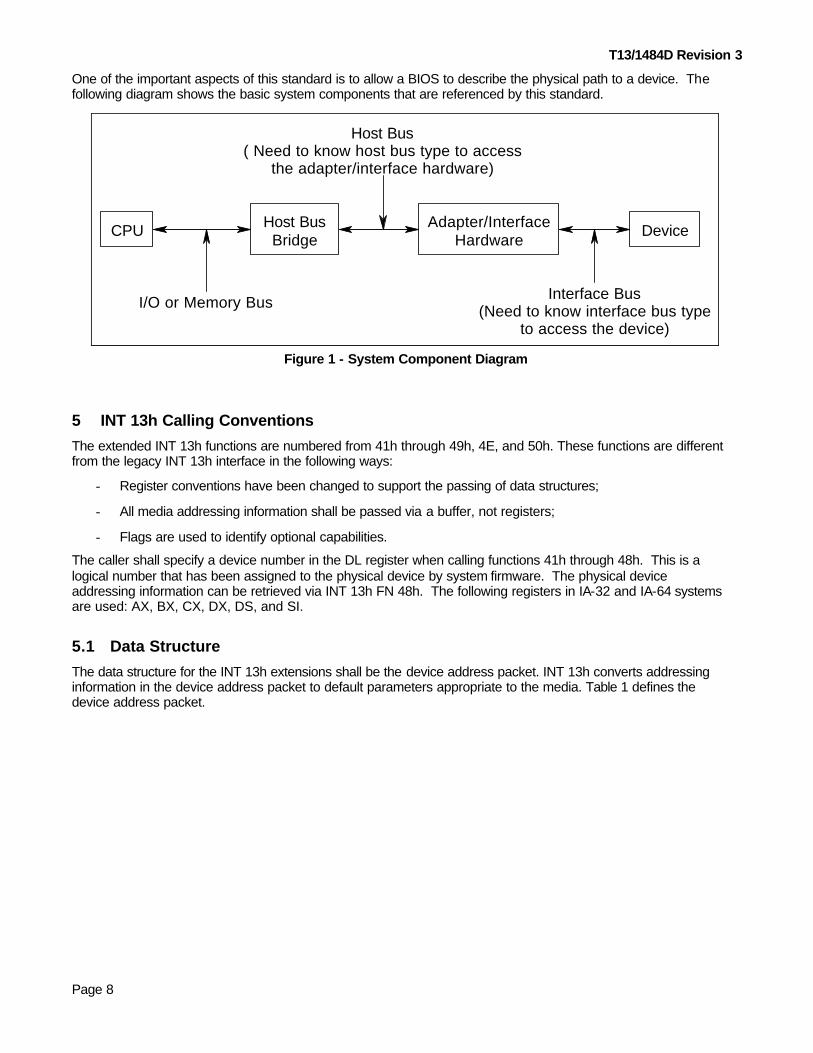
One of the important aspects of this standard is to allow a BIOS to describe the physical path to a device. The following diagram shows the basic system components that are referenced by this standard.
CPU DeviceAdapter/InterfaceHardware
Host BusBridge
I/O or Memory Bus
Host Bus( Need to know host bus type to access
the adapter/interface hardware)
Interface Bus(Need to know interface bus type
to access the device)
Figure 1 - System Component Diagram
5 INT 13h Calling Conventions
The extended INT 13h functions are numbered from 41h through 49h, 4E, and 50h. These functions are different from the legacy INT 13h interface in the following ways:
Register conventions have been changed to support the passing of data structures;
All media addressing information shall be passed via a buffer, not registers;
Flags are used to identify optional capabilities.
The caller shall specify a device number in the DL register when calling functions 41h through 48h. This is a logical number that has been assigned to the physical device by system firmware. The physical device addressing information can be retrieved via INT 13h FN 48h. The following registers in IA-32 and IA-64 systems are used: AX, BX, CX, DX, DS, and SI.
5.1 Data Structure
The data structure for the INT 13h extensions shall be the device address packet. INT 13h converts addressing information in the device address packet to default parameters appropriate to the media. Table 1 defines the device address packet.

T13/1484D Revision 3
Page 9
Table 1 - Device Address Packet
Offset Type Description
0 Byte Packet size in bytes. The value in this field shall be 16 (10h) or greater. If the packet size is less than 16 the request shall be rejected with CF = 1b and AH = 01h.
1 Byte Reserved. The value in this field shall be 00h
2 Byte Number of blocks to transfer. This field shall contain a maximum value of 127 (7Fh). If a any other value is supplied, the request shall be rejected with CF=1b and AH=01h. If this field is set to FFh, then the transfer buffer address shall be found at offset 10h, the number of blocks to transfer shall be found at offset 18h, and the transfer buffer at offset 4 shall be ignored. A block count of 0 means no data shall be transferred.
3 Byte Reserved. The value in this field shall be 00h.
4 DWord Address of host transfer buffer. This is the host buffer that Read/Write operations shall use to transfer the data. This is a 32-bit host address of the form Seg:Offset. If this field is set to FFFFh:FFFFh then the address of the transfer buffer shall be found at offset 10h.
8 QWord Starting logical block address, on the target device, of the data to be transferred. This is a 64-bit unsigned linear address. If the device supports LBA addressing this value should be passed unmodified. If the device does not support LBA addressing the callee shall convert this LBA to a CHS address using the current geometry in the following formula:
LBA = (C1 * H0 + H1) * S0 + S1 - 1
Where: C1 = Selected Cylinder Number H0 = Number of Heads (Maximum Head Number + 1) H1 = Selected Head Number S0 = Maximum Sector Number S1 = Selected Sector Number
For ATA compatible devices, with less than or equal to 15,482,880 logical sectors, the H0 and S0 values are supplied by words 3 and 6 of the data returned as a result of an IDENTIFY DEVICE command.
10h QWord 64-bit unsigned linear address of the host transfer buffer. This is the host buffer that Read/Write operations shall use to transfer the data if the data at offset 4 is set to FFFFh:FFFFh, or the data at offset 2 is set to FFh.
18h DWord Total number of blocks to transfer when the data at offset 2 is set to FFh
1Ch DWord Reserved. The value in this field shall be 00h. NOTE - The options described in table 1 allow a host to use a 7-bit transfer size with a 32 –bit or 64-bit memory address for the transfer buffer. Table 1 also allows a 32-bit transfer size in conjunction with a 64-bit address. A 32-bit transfer size shall not be used in conjunction with a 32-bit memory address.
5.2 Removable Media
The distinction between "removable" disks numbered 00h through 7Fh and "fixed" disks numbered 80h through FFh differs from conventional INT 13h functions. Devices numbered 0 through 7Fh are not changed. They follow conventional INT 13h standards for floppy disk operation. Devices numbered 80h through FFh include traditional fixed disks, and now also include removable media devices that support media change notification as well as software locking and unlocking capabilities. Functions in this standard support these devices. Return codes defined for the conventional INT 13h interface are vendor specific and may be used. In addition the following return codes support removable media:
T13/1484D Revision 3
Page 10
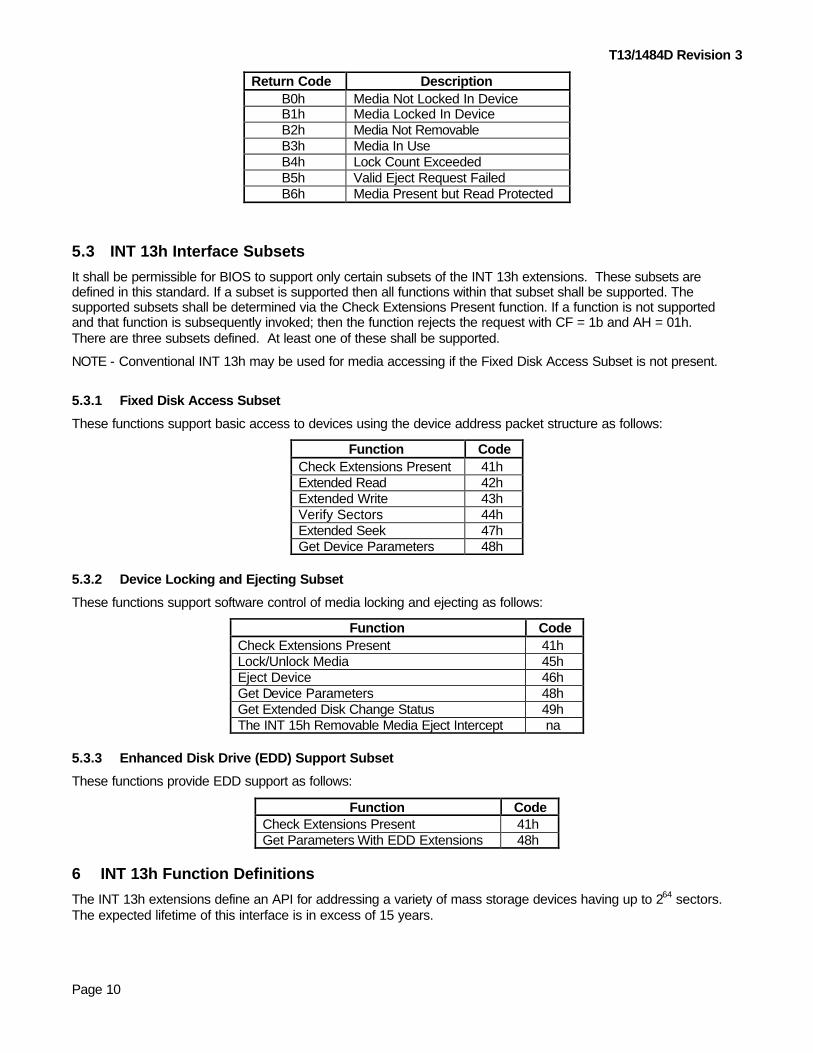
Return Code Description B0h Media Not Locked In Device B1h Media Locked In Device B2h Media Not Removable B3h Media In Use B4h Lock Count Exceeded B5h Valid Eject Request Failed B6h Media Present but Read Protected
5.3 INT 13h Interface Subsets
It shall be permissible for BIOS to support only certain subsets of the INT 13h extensions. These subsets are defined in this standard. If a subset is supported then all functions within that subset shall be supported. The supported subsets shall be determined via the Check Extensions Present function. If a function is not supported and that function is subsequently invoked; then the function rejects the request with CF = 1b and AH = 01h. There are three subsets defined. At least one of these shall be supported.
NOTE - Conventional INT 13h may be used for media accessing if the Fixed Disk Access Subset is not present.
5.3.1 Fixed Disk Access Subset
These functions support basic access to devices using the device address packet structure as follows:
Function Code Check Extensions Present 41h Extended Read 42h Extended Write 43h Verify Sectors 44h Extended Seek 47h Get Device Parameters 48h
5.3.2 Device Locking and Ejecting Subset
These functions support software control of media locking and ejecting as follows:
Function Code Check Extensions Present 41h Lock/Unlock Media 45h Eject Device 46h Get Device Parameters 48h Get Extended Disk Change Status 49h The INT 15h Removable Media Eject Intercept na
5.3.3 Enhanced Disk Drive (EDD) Support Subset
These functions provide EDD support as follows:
Function Code Check Extensions Present 41h Get Parameters With EDD Extensions 48h
6 INT 13h Function Definitions
The INT 13h extensions define an API for addressing a variety of mass storage devices having up to 264 sectors. The expected lifetime of this interface is in excess of 15 years.
T13/1484D Revision 3
Page 11
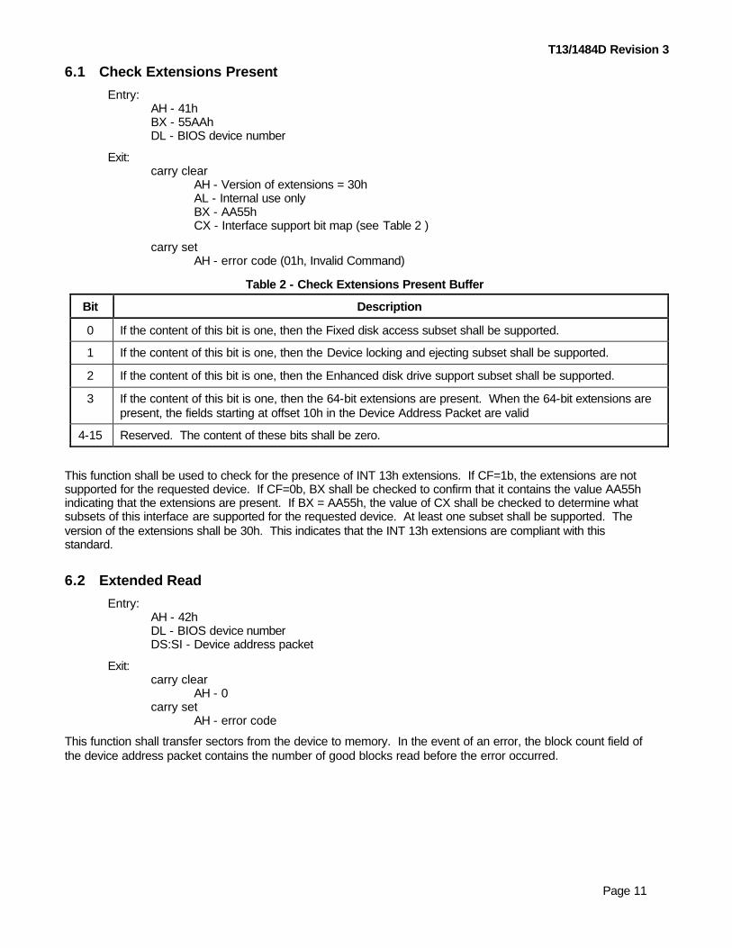
6.1 Check Extensions Present
Entry: AH - 41h BX - 55AAh DL - BIOS device number
Exit: carry clear AH - Version of extensions = 30h AL - Internal use only BX - AA55h CX - Interface support bit map (see Table 2 )
carry set AH - error code (01h, Invalid Command)
Table 2 - Check Extensions Present Buffer
Bit Description
0 If the content of this bit is one, then the Fixed disk access subset shall be supported.
1 If the content of this bit is one, then the Device locking and ejecting subset shall be supported.
2 If the content of this bit is one, then the Enhanced disk drive support subset shall be supported.
3 If the content of this bit is one, then the 64-bit extensions are present. When the 64-bit extensions are present, the fields starting at offset 10h in the Device Address Packet are valid
4-15 Reserved. The content of these bits shall be zero.
This function shall be used to check for the presence of INT 13h extensions. If CF=1b, the extensions are not supported for the requested device. If CF=0b, BX shall be checked to confirm that it contains the value AA55h indicating that the extensions are present. If BX = AA55h, the value of CX shall be checked to determine what subsets of this interface are supported for the requested device. At least one subset shall be supported. The version of the extensions shall be 30h. This indicates that the INT 13h extensions are compliant with this standard.
6.2 Extended Read
Entry: AH - 42h DL - BIOS device number DS:SI - Device address packet
Exit: carry clear AH - 0 carry set AH - error code
This function shall transfer sectors from the device to memory. In the event of an error, the block count field of the device address packet contains the number of good blocks read before the error occurred.

T13/1484D Revision 3
Page 12
6.3 Extended Write
Entry: AH - 43h AL - 0 or 1, write with verify off 2, write with verify on DL - BIOS device number DS:SI - Device address packet
Exit: carry clear AH - 0 carry set AH - error code
This function shall transfer sectors from memory to the device. If write with verify is not supported, this function rejects the request with AH = 01h and CF = 1b. Fn 48h shall be used to detect if write with verify is supported. In the event of an error, the block count field of the device address packet contains the number of blocks transferred before the error occurred. The calling software should not assume that the data transferred is validly written to the media. AL also contains the values 00h, 01h, or 02h. This function rejects all other values with AH = 01h and CF = 1b.
6.4 Verify Sectors
Entry:
AH - 44h DL - BIOS device number DS:SI - Device address packet
Exit: carry clear AH - 0 carry set AH - error code
This function verifies sectors without transferring data between the device and system memory. When an error is reported the block count field of the device address packet shall be filled in with the number of blocks verified before the error occurred.
6.5 Lock/Unlock Media
Entry: AH - 45h AL - 0 - Lock media in device 1 - Unlock media in device 2 - Return lock/unlock status 3h-FFh - Invalid DL - BIOS device number
Exit: carry clear AH - 0 AL - 1 if device is locked, 0 if not carry set AH - error code.
This function logically locks or unlocks removable media in a specific device. All removable media devices numbered 80h and above shall implement this function. If a fixed disk (non-removable device) supports the media locking and ejecting subset, this function shall return with success (i.e., AH = 00h and CF = 0b). There shall be support for 255 locks per device. A device shall not be unlocked until all locks to that device have been released with unlock commands. Excess unlock calls shall return with CF = 1b and AH = B0h. If the number of

T13/1484D Revision 3
Page 13
locks supported value is exceeded on a lock request, this function shall reject the request with CF = 1b and AH = B4h. Locking a device without media present shall be a valid operation. On return from a lock or unlock request, AL shall contain the lock state of the media as maintained by the BIOS. This provides for unlock requests when the lock count is greater than zero. In this case, the media shall remain locked. Any physical locking and unlocking of the media shall be implementation dependent, but the caller may operate on the assumption that locked media cannot be removed without an unlock request. After power-on, or a system reset, all devices shall automatically enter an unlocked state.
6.6 Eject Removable Media
Entry: AH - 46h AL - 0h DL - BIOS device number
Exit: carry clear AH - 0 carry set AH - error code
This function shall eject media from the specified device. If a fixed disk (non-removable device) supports the media locking and ejecting interface subset, this function shall always return with “Volume Not Removable” (i.e., CF = 1 and AH = B2h). An attempt to eject media locked in a device shall return with “Media Locked In Device” (i.e., CF 1 and AH = B1h). This function represents a request to remove media from the selected device. Actual ejection shall be implementation dependent, but system software that issues or observes this function should flush any buffers it is holding. If this function is issued for a device without media the request shall be returned with “No Media In Device” (i.e., CF = 1b and AH = 31h). If this call is issued to an unlocked removable media device that has media present, an INT 15h, Fn 52h (removable media eject) shall be issued to determine if eject removable media may proceed with the ejection request. If INT 15h returns an error, the ejection request shall be rejected. If the ejection request is accepted, followed by an unrecoverable error, this function shall return with “Valid Eject Request Failed” (i.e., CF = 1b and AH = B5h).
6.7 Extended Seek
Entry: AH - 47h DL - BIOS device number DS:SI - Device address packet
Exit: carry clear AH - 0 carry set AH - error code
This function allows the host to provide advanced notification that particular data may be requested by the host in a subsequent command. This command shall initiate a seek operation. The seek may not be complete when this function completes.
6.8 Get Device Parameters
Entry: AH - 48h DL - BIOS device number DS:SI - address of result buffer.
Exit: carry clear AH - 0 DS:SI - address of result buffer

T13/1484D Revision 3
Page 14
carry set AH - error code
This function returns default device parameters. It shall be mandatory regardless of the interface subset that is supported. Table 3 defines the result buffer. On entry the first word of the result buffer shall be the buffer length in bytes.
Table 3 - Result Buffer
Offset Type Description
0 Word The caller shall set this value to the maximum buffer length in bytes. If the length of this buffer is less than 30 bytes, this function shall not return the pointer to DPT extension. If the buffer length is 30 or greater on entry, it shall be set to 30 on exit. If the buffer length is between 26 and 29, it shall be set to 26 on exit. If the buffer length is less than 26 on entry an error shall be returned.
2 Word Information Flags. A value of one in a bit indicates that the feature shall be available. A value of zero in a bit indicates the feature shall be not available and shall operate in a manner consistent with the conventional INT 13h interface.
Bit Description 0
1 2 3 4 5 6
7 8-15
DMA boundary errors are handled transparently The geometry returned in bytes 4-15 shall be valid Media shall be removable. Bits 4-6 are not valid if this bit is cleared to zero Device supports write verify Device has media change notification Media shall be lockable Device geometry shall be set to maximum and no media shall be present when this bit is set to one BIOS calls INT13h FN 50h to access the device Reserved
4 DWord Number of default cylinders. The content of this field shall be one greater than the maximum cylinder number. INT 13h Fn 08h shall be used to find the logical number of cylinders.
8 DWord Number of default heads. The content of this field shall be one greater than the maximum head number. INT 13h Fn 08h shall be used to find the logical number of heads.
12 DWord Number of default sectors per track. The content of this field shall be the same as the maximum sector number because sector addresses are 1 based. INT 13h Fn 08h shall be used to find the logical number of sectors per track.
16 QWord Number of sectors. This shall be one greater than the maximum sector number. If this field is greater than 15,482,880 then word 2, bit 1 shall be cleared to zero.
24 Word Number of bytes in a sector.
26 DWord Pointer to the Device Parameter Table Extension (DPTE). This field follows the seg:offset address format. The DPTE shall only be present if INT 13h, Fn 41h, CX register bit 2 is set to one. This field points to a temporary buffer that the BIOS may invalidate on subsequent INT 13h calls. A value of FFFFh:FFFFh in this field means that the DPTE is not present. If the length of this result buffer is less than 30, the DPTE shall not be present. This field is only used for legacy INT 13h based systems configured with ATA or ATAPI devices.
30 Word 0BEDDh – Key, indicates presence of Device Path Information
32 Byte Length of Device Path Information including the key. The content of this byte shall be 44h
33 Byte Reserved. The value in this field shall be 00h.
34 Word Reserved. The value in this field shall be 0000h.

T13/1484D Revision 3
Page 15
Offset Type Description
36 ASCII Host bus type, 4 bytes. ASCII data shall be left justified and padded with the value 20h
PCI ISA
PCI-X
PCI Local Bus Legacy 16 bit fixed bus PCI-X Bus
50h 43h 49h 20h 49h 53h 41h 20h 50h 43h 49h 58h
40 ASCII Interface type, 8 bytes. ASCII data shall be left justified and padded with the value 20h
ATA ATAPI SCSI USB 1394
FIBRE I2O
RAID SATA
ATA/ATAPI compliant device using ATA commands ATA/ATAPI compliant device using ATAPI commands SCSI compliant device USB Mass Storage compliant device 1394 Mass Storage device Fibre Channel Intelligent Input/Output Redundant Array of Inexpensive Disks (RAID) member Serial ATA
41h 54h 41h 20h 20h 20h 20h 20h 41h 54h 41h 50h 49h 20h 20h 20h 53h 43h 53h 49h 20h 20h 20h 20h 55h 53h 42h 20h 20h 20h 20h 20h 31h 33h 39h 34h 20h 20h 20h 20h 46h 49h 42h 52h 45h 20h 20h 20h 49h 32h 4Fh 20h 20h 20h 20h 20h 52h 41h 49h 44h 20h 20h 20h 20h 53h 41h 54h 41h 20h 20h 20h 20h
48 QWord Interface Path, 8 bytes. See below for format information
56 Double QWord
Device Path. See below for format information.
72 Byte Reserved. The value in this field shall be 00h.
73 Byte Checksum for Device Path Information includes the 0BEDDh signature. The content of this field shall be the two’s complement of the unsigned sum of offset 30 through 72. The unsigned sum of offset 30 through 73 shall be 0.

T13/1484D Revision 3
Page 16
6.8.1 Interface Path
The Interface Path field at offset 48 allows software external to a system BIOS to locate mass storage device interface chips. The format of this field shall be dependent on the Host Bus type, offsets 36 through 39 of the result buffer. The following formats are currently defined:
Table 4 - Interface Path Definitions
Host Bus Type
Offset Type Definition
ISA 48 Word 16-bit base address
50 Word Reserved. The value in this field shall be 0000h
52 DWord Reserved. The value in this field shall be 00000000h
PCI 48 Byte PCI bus number. Values 00h through FEh shall represent a valid PCI bus. Value FFh shall indicate that this field is not used.
49 Byte PCI slot number. Values 00h through FEh shall represent a valid PCI slot. Value FFh shall indicate that this field is not used.
50 Byte PCI function number. Values 00h through FEh shall represent a valid PCI function. Value FFh shall indicate that this field is not used.
51 Byte Channel number. If more than one interface of the same type is in a single Bus, Slot, Function, then the channel number shall identify each interface. If there is only one interface, the content of this field shall be cleared to zero. If there are two interfaces, such as an ATA Primary and Secondary interface, the primary interface shall be zero, and the secondary interface shall be one.
Values 00h through FEh shall represent a valid Channel Number. Value FFh shall indicate that this field is not used
52 DWord Reserved. The value in this field shall be 00000000h
PCI-X 48 Byte PCI-X bus number. Values 00h through FEh shall represent a valid PCI bus. Value FFh shall indicate that this field is not used.
49 Byte PCI slot number. Values 00h through FEh shall represent a valid PCI slot. Value FFh shall indicate that this field is not used.
50 Byte PCI function number. Values 00h through FEh shall represent a valid PCI function. Value FFh shall indicate that this field is not used.
51 Byte Channel number. If more than one interface of the same type is in a single Bus, Slot, Function, then the channel number shall identify each interface. If there is only one interface, the content of this field shall be cleared to zero. If there are two interfaces, such as an ATA Primary and Secondary interface, the primary interface shall be zero, and the secondary interface shall be one.
Values 00h through FEh shall represent a valid Channel Number. Value FFh shall indicate that this field is not used
52 DWord Reserved. The value in this field shall be 00000000h

T13/1484D Revision 3
Page 17
6.8.2 Device Path
The Device Path at offset 56 combined with the Interface Path allows software external to a system BIOS to locate a specific mass storage device. The Device Path field provides a path from an interface to a specific device. The format of the Device Path at offset 40 through 47 is dependent on the Interface type. The following formats are defined in this standard:
Table 5 - Device Path Definitions
Interface Type Offset Type Definition
ATA 56 Byte 00h = ATA Device 0, 01h = ATA Device 1
57 Byte Reserved. The value in this field shall be 00h.
58 Word Reserved. The value in this field shall be 0000h.
60 DWord Reserved. The value in this field shall be 00000000h.
64 QWord Reserved. The value in this field shall be 0000000000000000h.
ATAPI 56 Byte 00h = ATAPI Device 0, 01h = ATAPI Device 1
57 Byte Logical Unit Number
58 Byte Reserved. The value in this field shall be 00h.
59 Byte Reserved. The value in this field shall be 00h.
60 DWord Reserved. The value in this field shall be 00000000h.
64 QWord Reserved. The value in this field shall be 0000000000000000h.
SCSI 56 Word Physical Unit Number/SCSI ID
58 QWord Logical Unit Number
66 Word Reserved. The value in this field shall be 0000h.
68 DWord Reserved. The value in this field shall be 00000000h.
USB 56 QWord 64-bit Serial Number as defined in the USB Mass Storage specifications
64 QWord Reserved. The value in this field shall be 0000000000000000h.
1394 56 QWord 64-bit Extended Unique Identifier (EUI-64)
64 QWord Reserved. The value in this field shall be 0000000000000000h.
FIBRE 56 QWord 64-bit Worldwide Identifier (WWID)
64 QWord Logical Unit Number
I2O 56 QWord 64-bit Identity Tag
64 QWord Reserved. The value in this field shall be 0000000000000000h.
RAID 56 DWord RAID array number of which this device is a member
60 DWord Reserved. The value in this field shall be 00000000h.
64 QWord Reserved. The value in this field shall be 0000000000000000h.
T13/1484D Revision 3
Page 18
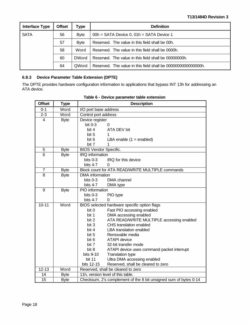
Interface Type Offset Type Definition
SATA 56 Byte 00h = SATA Device 0, 01h = SATA Device 1
57 Byte Reserved. The value in this field shall be 00h.
58 Word Reserved. The value in this field shall be 0000h.
60 DWord Reserved. The value in this field shall be 00000000h.
64 QWord Reserved. The value in this field shall be 0000000000000000h.
6.8.3 Device Parameter Table Extension (DPTE)
The DPTE provides hardware configuration information to applications that bypass INT 13h for addressing an ATA device.
Table 6 - Device parameter table extension
Offset Type Description 0-1 Word I/O port base address 2-3 Word Control port address 4 Byte Device register bit 0-3
bit 4 bit 5 bit 6 bit 7
0 ATA DEV bit 1 LBA enable (1 = enabled) 1
5 Byte BIOS Vendor Specific. 6 Byte IRQ information bits 0-3
bits 4-7 IRQ for this device 0
7 Byte Block count for ATA READ/WRITE MULTIPLE commands 8 Byte DMA information bits 0-3
bits 4-7 DMA channel DMA type
9 Byte PIO information bits 0-3
bits 4-7 PIO type 0
10-11 Word BIOS selected hardware specific option flags bit 0
bit 1 bit 2 bit 3 bit 4 bit 5 bit 6 bit 7 bit 8
bits 9-10 bit 11
bits 12-15
Fast PIO accessing enabled DMA accessing enabled ATA READ/WRITE MULTIPLE accessing enabled CHS translation enabled LBA translation enabled Removable media ATAPI device 32-bit transfer mode ATAPI device uses command packet interrupt Translation type Ultra DMA accessing enabled Reserved, shall be cleared to zero
12-13 Word Reserved, shall be cleared to zero 14 Byte 11h, version level of this table. 15 Byte Checksum, 2’s complement of the 8 bit unsigned sum of bytes 0-14

T13/1484D Revision 3
Page 19
6.8.3.1 Offset 0-1 - I/O port base
This word is the 16-bit address in I/O space of the data register in the ATA Command Block. Any application that provides a proprietary interface to the device may use this base address.
6.8.3.2 Offset 2-3 - control port base
This word is the 16-bit address in I/O space of the device control register. Any application that provides a proprietary interface to the device may use this address.
6.8.3.3 Offset 4 - head prefix
The upper four bits of this byte shall be logically ORed with the head number, or upper four bits of the LBA, each time the disk is addressed. It contains the ATA DEV bit and the LBA addressing bits that are preset, and makes these functions transparent to any software using this extension. The LBA addressing bit is set for each disk access and shall not be used to determine the LBA capability of the system. See the LBA translation enabled bit described in section 6.8.3.9.5 for system LBA capability.
6.8.3.4 Offset 5 - BIOS use only
BIOS use only.
6.8.3.5 Offset 6 - IRQ number
Each ATA channel requires an assigned Interrupt number. This byte identifies which IRQ is used by this device’s channel.
6.8.3.6 Offset 7 - READ/WRITE MULTIPLE command block count
If the device was configured to use the READ/WRITE MULTIPLE command, then this field shall contain the block size of the transfer, in sectors, used by the BIOS.
6.8.3.7 Offset 8 - DMA channel/Multiword DMA Type
If the BIOS has configured the system to perform multiword DMA data transfers in place of PIO transfers, this field shall specify the DMA mode in the upper four bits, as per the definition in ATA-5 or later, and the DMA Channel in the lower four bits. ATA channels that support PCI DMA bus mastering shall set the DMA channel to zero. Note that the DMA Type field does not follow the format of the data returned by the device. The value of the DMA mode shall not be limited to two.
6.8.3.8 Offset 9 - PIO type
If the BIOS has configured the system to perform PIO data transfers other than mode 0, this field shall specify the PIO mode as per the definition in ATA-5 or later.
6.8.3.9 Offset 10-11 - BIOS selected hardware specific option flags
These bytes specify the current hardware options enabled by the BIOS, a bit for each of the options listed below.
6.8.3.9.1 Bit 0 - fast PIO
If the system is configured for a PIO mode greater than 0, this bit shall be set to one and byte 9 (PIO Type) shall be used to configure the system. If this bit is cleared to zero, the PIO-Type field shall be ignored.

T13/1484D Revision 3
Page 20
6.8.3.9.2 Bit 1 - fast DMA
If the system is configured for DMA, this bit shall be set to one and byte 8 (DMA Channel/DMA Type) should be used to configure the system. If this bit and bit 11, section 3.5.9.11, are cleared to zero, then the DMA Channel/DMA Type field shall be ignored.
6.8.3.9.3 Bit 2 - ATA READ/WRITE MULTIPLE
If the system is configured for multi-sector transfers, this bit shall be set to one and byte 7 (sector count) specifies the number of sectors used for each data transfer. If block PIO is disabled, ignore the block count field.
6.8.3.9.4 Bit 3 - CHS translation
If the device reports more than 1024 cylinders in the IDENTIFY DEVICE command data, this bit shall be set to one. See section 6.8.3.9.10 to determine the method of geometry translation.
6.8.3.9.5 Bit 4 - LBA translation
If the system is configured for LBA type addressing, this bit shall be set to one and the Extended INT 13h interface (Fn 41h through 48h) shall pass LBA values directly to the device. The conventional INT 13h interface shall ignore this bit and shall use CHS. LBA-type addressing shall be available on devices with less than 1024 cylinders, and therefore bit 3 (CHS translation) shall be independent from bit 4 (LBA translation).
6.8.3.9.6 Bit 5 - removable media
If the device supports removable media, this bit shall be set to one and the extended INT 13h device locking and ejecting subset shall also be supported.
6.8.3.9.7 Bit 6 - ATAPI device
If this ATA device implements the PACKET command feature set (ATAPI) as defined in ATA/ATAPI-5, this bit shall be set to one.
6.8.3.9.8 Bit 7 - 32-bit transfer mode
If the BIOS has configured the host adapter to perform 32-bit wide data transfers, this bit shall be set to one.
6.8.3.9.9 Bit 8 - ATAPI device uses command packet interrupt
If bit 6 is cleared to zero, then this field shall be ignored and shall be zero. If bit 6 is set to one, this bit indicates how the ATAPI devices signals it is ready to receive a packet command. When this bit is set to one, it indicates that the ATAPI device returns an interrupt, and sets DRQ, when it is ready for a packet. When this bit is cleared to zero, it indicates that the ATAPI device sets DRQ, without an interrupt, when it is ready for a packet.
6.8.3.9.10 Bits 9-10 - translation type
If bit 3 is cleared to zero then this field shall be ignored and shall be zero. If bit 3 is set to one then this field identifies the geometric translation shown in Table 7 .
Table 7 - Translation Type
Bits 9-10 Description
00 Bit-shift translation
01 LBA assisted translation
10 Reserved
11 Vendor specific translation
T13/1484D Revision 3
Page 21
6.8.3.9.11 Bit 11 - Ultra DMA
If the system is configured for Ultra DMA, this bit shall be set to one and byte 8 (DMA Channel/DMA Type) should be used to configure the system. If this bit and bit 1, (Bit 1 - fast DMA, section 6.8.3.9.2) are cleared to zero, then the DMA Channel/DMA Type field shall be ignored.
6.8.3.9.12 Bits 12-15 - Reserved
Shall be cleared to zero.
6.8.3.10 Offset 12-13 - Reserved
Shall be cleared to zero.
6.8.3.11 Offset 14 - table revision
The table version shall be set to 11h indicating compliance with this standard.
6.8.3.12 Offset 15 - checksum
This shall be the two's complement of the 8-bit unsigned sum of bytes 0 through 14. Adding bytes 0 through 15 shall in all cases produce an 8-bit result of zero.
6.9 Get Extended Media Change Status
Entry: AH - 49h DL - BIOS device number
Exit: carry clear AH - 00, change-line inactive carry set AH - 06, change-line active
This function returns media change status. If it returns with CF = 1b, the media may not have been changed. The media change notification may be activated by unlocking and locking the device door without removing the media. This function corresponds to INT 13h Fn 16h, but explicitly allows any device number to be passed in. If a non-removable device supports the Device Locking and Ejecting interface subset, this function shall return with success, AH = 00h, CF = 0b. This function shall clear the media change notification on exit.

T13/1484D Revision 3
Page 22
6.10 Set Hardware Configuration
Entry:
AH - 4Eh AL - Hardware configuration sub-function (See Table 8) DL - BIOS device number.
Exit: carry clear AH - 0 AL - 0 if command was safe 1 if other devices are affected carry set AH - error code
Table 8 - Hardware Configuration Sub-Functions
AL Sub-function description 0h Enable prefetch 1h Disable prefetch 2h Set maximum PIO transfer mode. 3h Set PIO mode 0. 4h Return to default PIO transfer mode. Return the system to the PIO mode enabled by the BIOS
setup utility. 5h Enable INT 13h DMA maximum mode. Set the maximum rate allowed by both the host
adapter and the device. 6h Disable INT 13h DMA
The purpose of this function is to allow non-hardware-specific software to configure host adapter and devices for optimal operation. ATA channels may have two devices attached, but this function operates on a single-device basis. This shall be accommodated by the value that is returned in AL. If the host adapter supports the requested sub-function on a device basis, AL shall be cleared to 00h. If the host adapter only supports the setting on an ATA channel basis, AL shall be set to 01h. Once this function has been invoked, all subsequent INT 13h device-access functions shall use the mode specified by this invocation. This means that if “DMA Maximum” is enabled, INT 13h Fn 02h shall read from the device using DMA transfers. The DMA/PIO selections are mutually exclusive. When “DMA Maximum” is enabled, “PIO Maximum” shall be disabled. If the requested mode change is not supported this function shall return with CF = 1b and AH = 01h

T13/1484D Revision 3
Page 23
6.11 Send Packet Command
Entry:
AH - 50h AL – D7h DL - BIOS device Number ES:SI – Pointer to formatted command packet, (see Table 9).
Exit: carry clear AH - 0 carry set AH - error code 01 – Function not implemented 80h – Command failed to complete 97h – Subfunction D7h not supported for this device C3h – Formatted Command Packet is too short
Table 9 - Formatted Command Packet
Offset Type Description 0 Word Length of this record in bytes
2-n Byte Formatted protocol specific data
This function defines a service that the system BIOS shall call for sending data to and from a packet oriented device. The BIOS shall provide this service before the OS is loaded. When an operating system takes control of the device controller it takes the hook for this service to provide a seamless transfer of control from the BIOS to the operating system. This service allows several BIOS level services to continue functioning, even after the OS has taken control of the device controller, for example:
The INT 13h mass storage interface
Power Management
Suspend to disk
The BIOS is a single threaded, master device. This means that the BIOS shall not process asynchronous requests from other devices. The BIOS shall send commands to devices and wait for responses. This means that the operating system may take control of the serial interface with no hand-off information from the system BIOS. The operating system shall reconfigure the interface and hook the service described above. The system BIOS may provide INT 13h Fn 50h for the 1394, USB, and any other packet oriented bus.
The format of the packet shall be determined by the requirements of the target bus and is beyond the scope of this document. In the case of USB, the packet format shall be determined by the USB specification. In the case of 1394, IEEE 1394-1995 shall determine the size of a packet with payload information defined in SBP-2.
6.11.1 Packet Sending Service (PSS) For SCSI Command Data Block’s (CDB)
The purpose of this interface is to allow an application to send SCSI CDB’s using BIOS INT 13h calls to a device, regardless of the bus on which the device resides. This interface is currently defined for ATAPI, SCSI, 1394, and USB devices. Future buses that use SCSI CDB’s may also adopt this mechanism for transporting commands
This interface shall not retry any operation. If an error occurs either in command format, or operation of the device, an error shall be returned by INT 13h. The application may choose to retry a command by issuing it again.
This PSS shall provide transport specific wrappers and modify the CDB where necessary with bus specific information. If the secondary bus is a hot-plug bus such as 1394 or USB, the PSS shall insert device addresses or EUI-64 as necessary. In the event that a device address changes due to a bus reset or re-enumeration, the PSS shall connect with the device without generating an error.

T13/1484D Revision 3
Page 24
6.11.1.1 Formatted Protocol Specific Data
Table 10 defines the format of the data passed in ES:SI (See 6.11) to INT 13h Fn 50h.
Table 10 - Formatted Protocol Specific Data
Offset Type Description
0 Word Packet length in bytes including this word
2 Byte Information flags
Bits 6-7 = Data direction.
00 = No data exchanged with device (command only)
01 = Receive data from device
10 = Send data to device
11 = Reset Interface.
Bits 0-5 = Reserved.
3 Byte Bytes in command packet, or zero if no command is to be sent.
4 DWord Pointer to command packet. This field follows the seg:offset address format. This field is ignored if offset 3 is zero.
8 DWord Number of bytes to transfer following command complete. Shall be a multiple of the sector size of the media, as returned by Function 48h. If the data direction bits in Flags do not indicate a send or receive data command, then this field shall be ignored. Otherwise, if this value shall be zero, then a 0-byte transfer shall occur.
10h DWord Pointer to the start of the data stream to transfer. This field follows the seg:offset address format.
14 Word Access timeout. Maximum time in milliseconds to wait for command start. Command start includes sending the command to the devices and waiting for the first data byte to transfer.
If this field contains the value of 0000h, an 80h error shall result
16 Word Sector timeout increment. The PSS shall divide the amount of data transferred by the sector size, round up, multiply by this value, and add to the Access Timeout (offset 14), the maximum result is limited to FFFFh. This shall be the total timeout for the specified CDB. This value shall be ignored for command-only and bus-reset calls.

T13/1484D Revision 3
Page 25
6.11.1.2 Output Parameters
The following output parameters, see Table 11, match the parameters defined in 6.11. No other return parameters are necessary for this transport.
Table 11 – Output Parameters
OUT Description
AL Undefined
Value Description
00h No Error
01h AX=50D7h not implemented
80h
A condition has occurred which prevented successful command completion. This may be due to a busy device, a timeout, a bus reset, short packet, or other event. The host should issue a Request-Sense-type command in the required protocol.
97h There is no support for the indicated logical drive, although Function 50D7h is recognized.
C3h PSSP is too short.
Remaining Values Reserved
AH
All other registers Preserved
Carry flag 0 if AH is cleared to zero
1 if AH is 1through FFh.
7 INT 15h Removable Media Eject
Entry: AH - 52h DL - BIOS device number
Exit: carry clear AH - 0, ejection may proceed carry set AH - error code, B1h or B3h, ejection is rejected
This function shall be called by the BIOS in response to a software request (INT 13h, AH=46h, Eject Device) to eject media from a removable media device.
A user may press an eject button or use a software command to request that a particular media be ejected. By default the INT15h handler returns with ejection accepted status. A disk cache program may hook this INT15h call and return acceptance or rejection based on the state of its buffers for this disk. This function may also be used by operating system software as a media change request.