t10y mca user’s manual - elmarksupport.elmark.com.pl/getac/pdf/durabook/user's manual.pdf ·...
TRANSCRIPT
TT1100YY MMCCAA
UUsseerr’’ss MMaannuuaall
ii
Table Of Contents
CHAPTER 1 GETTING STARTED 1
Getting Started ................................................................................... 2
Inventory ............................................................................................. 3
Safety and Maintenance .................................................................... 4
Checklists ........................................................................................... 5
Features .............................................................................................. 6
Where to Look For Information ........................................................ 7
Quick Start .......................................................................................... 8
Loading Windows .............................................................................. 9
Adjusting the Volume ...................................................................... 10
Adjusting the Brightness ................................................................ 10
Turning off Your MCA...................................................................... 11
CHAPTER 2 GETTING STARTED 12
Hardware and Software ................................................................... 13
Front View ......................................................................................... 14
Right View ......................................................................................... 15
Bottom View ..................................................................................... 16
Power Indicators .............................................................................. 17
Buttons.............................................................................................. 18
Function Keys .................................................................................. 19
Touch Pen......................................................................................... 20
Disk Drives........................................................................................ 20
LCD Screen....................................................................................... 22
Touch Screen ................................................................................... 23
Information about Fingerprint function ......................................... 25
Information about Barcode scanner .............................................. 26
How to use the Barcode scanner ................................................... 28
Information about RFID reader ....................................................... 29
Information about Camera function ............................................... 30
Communication Components......................................................... 32
Information about 3G function........................................................ 33
Information about Bluetooth function ........................................... 34
iii
CHAPTER 3 MAKING CONNECTIONS 35
Making Connections ........................................................................ 36
CHAPTER 4 POWER MANAGEMENT 37
Power Management ......................................................................... 38
When to Replace the Battery .......................................................... 39
Heat Considerations ........................................................................ 40
CHAPTER 5 DOCKING STATION CONNECTORS 41
Docking Station Connectors-Front & Left side............................. 42
Docking Station Connectors-Right side ........................................ 43
Docking Station Connectors-Top side........................................... 44
Mechanical Specification ................................................................ 45
APPENDIX A STATEMENTS 46
Statements ........................................................................................ 47
European Notice............................................................................... 48
Safety Compliance ........................................................................... 50
Battery Disposal............................................................................... 51
CAUTION FOR ADAPTER................................................................ 51
BATTERY CAUTION......................................................................... 51
REGULATORY INFORMATION(INTEL WIFI) .................................. 54

CChhaapptteerr 11
IInnttrroodduuccttiioonn
2
Getting Started
Congratulations on your purchase of a MCA. The mobile clinical assistant (MCA) is a category of mobile computing platform developed by Intel® to be a new usage model that is customized for healthcare-specific use at the point of care, supporting the workflow of nurses and clinicians. This mobile clinical assistant (MCA) integrates technology from Intel® Health.
With your MCA you will be able to organize and access important clinical information anywhere, anytime. In addition, you will be able to use the biometric fingerprint reader or authenticate your badge with the RFID reader.
This Manual contains all the information you need to set up and use your MCA. It describes all the features of the MCA in an easy-to-read yet thorough manner.
The Intel® Health brand signals the company’s specialization in healthcare and commitment to the healthcare industry while drawing on Intel’s rich heritage as a technology innovator. Intel is a trusted name associated with innovation, reliability, quality, and speed — attributes that resonate with key decision makers in the healthcare sector.
Intel and the Intel logo are trademarks of Intel Corporation in the U.S. and other countries.
3
Inventory
This MCA is designed for years of productive and pleasurable computing. Use this section to keep details of your purchase. This information will be required should you need to make repairs to your MCA during the warranty period. Update this section when you add new options.
DATE OF PURCHASE:
PLACE OF PURCHASE:
DEALER'S NAME:
DEALER'S ADDRESS:
TELEPHONE:
E-MAIL ADDRESS/WWW:
CONTACT PERSON:
MODEL NUMBER:
SERIAL NUMBER:
4
Safety and Maintenance
You can use your MCA under a wide range of environmental conditions. However, to ensure long use and continued high performance, consider the following factors when setting up your MCA:
• Follow all warnings and instructions noted in this documentation and in the Windows Help program.
• The first time you use your MCA, we recommend that you carefully read the Making Connections section of this manual and initialize the battery to ensure optimum battery performance.
• Unplug the MCA from the power outlet before cleaning. Use a damp cloth for cleaning. Do not use aerosols, solvents, or strong detergents.
• Slots and openings in the system cabinet are for ventilation purposes. Do not block or cover these openings or the system could overheat. Do not use or store the MCA near a source of heat or dust.
• On the base or rear panel of this MCA, there is a label with information on the power requirements of this system. These requirements must be followed. If you are unsure of your local power supply, consult your dealer or local Power Company.
• Do not step on or place anything on the power cord.
• If you use the MCA with an extension cord, ensure that the total ampere ratings of all the devices sharing the extension do not exceed the rating of the extension cord or the rating of the wall outlet.
• Never push foreign objects into the MCA through any of the slots or openings. Dangerous voltages are present, which could cause electric shock or fire, or damage sensitive components.
Cleaning the MCA To clean the MCA, wipe its surface gently using a soft cotton cloth slightly dampened with alcohol or disinfecting products. The device’s outer surfaces (plastic shell, seal, touch panel, buttons, docking base connector, barcode scanner window, etc) can resist (80% or less) Alcohol, bleach, iodine and common hospital disinfectants.
5
Checklists
After opening the package, carefully inspect the contents. If any of the items is missing or appear damaged, contact your dealer. The shipping carton should contain the following:
STANDARD
• A MCA with a hard disk drive
• Two standard batteries
• An AC adapter with power cord (I.T.E. AC power or Medical AC power)(Option)
• User's Manual (Installed in Hard Disk)
• Driver CD (Installed in Hard Disk)
OPTIONS
The following items are normally optional, but some vendors may include them in the standard package. Some items may not be available in some countries, or some vendors may choose not to carry all the items.
• Additional battery
• 3G module
• RFID reader
• Barcode scanner
• 2 mega pixels camera module
• Docking station
Caution: When purchasing any of the accessories
listed above, purchase only those accessories that
are approved for use with your MCA. The above
accessories are proprietary items. Your system
vendor can obtain these approved accessories. If
you use items that are not approved for use with
this MCA, you may cause your MCA to malfunction, or
to emit or receive electro-magnetic radiation in
excess of local regulations. For non-proprietary
accessories such as PC cards or printers, ensure
that the accessory functions properly in your MCA
before making the purchase. Your system vendor may
be able to recommend reliable brands and models.
6
Features
Software Included
Widows® XP Tablet PC Edition which includes:
• Microsoft® Internet Explorer
• Microsoft® Outlook Express
• Microsoft® Windows Media Player
Windows Vista® Business (Optional)
High performance Processors
� Intel® ULV U2100 1.06GHz CPU or above (FSB 533MHz)
� Intel® ULV Celeron® 423 1.06GHz CPU or above (FSB 533MHz)
Smart Display
Automatic screen orientation & brightness adjustment
Smart Touch
Fingertip & stylus accessible, automatically timing control & palm rejection implemented
Comprehensive Network Connection
� PAN: Bluetooth 2.1
� LAN: Wireless LAN 802.11 a/b/g/n
� MAN: 3G module (optional)
Versatile Integration
RFID Reader, Barcode Scanner, Fingerprint Reader, Webcam and Microphone Array
Unburdened Consideration
Slim, light weight, no noise (fanless), and “grip & go” ergonomic handle
Rugged Enhancement
Sustainable from the free drop (3 feet height) and severe ingress level (IP54)
7
Flexible Battery Supply
Long power supply up to 4.5 hrs
Extended Access Control
3 user programmable keys available to define
Rugged Standard
Drop Resistant: 26 drops of 36 inches to plywood over concrete with unit on
2 units to pass.
Water Sealing:
Rain chamber to operate at no less than 40 PSIG and no less than 4 in/hr. 10 min per axis, 6 axes, Unit is non-operating.
Where to Look For Information
About Your MCA
This User’s Manual describes the key elements of your MCA. New users can find a simple step-by-step orientation in the Quick Start section of this chapter.
About Windows
Windows Online Help, found on the Start menu, offers extensive Windows assistance. Welcome to Windows offers an online orientation for new Windows users. Find it in:
Start/Programs/Accessories/System Tools.
8
Quick Start
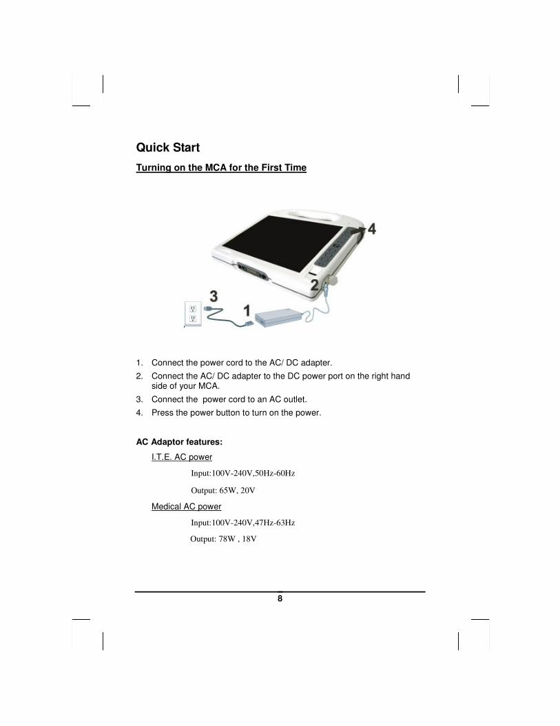
Turning on the MCA for the First Time
1. Connect the power cord to the AC/ DC adapter.
2. Connect the AC/ DC adapter to the DC power port on the right hand side of your MCA.
3. Connect the power cord to an AC outlet.
4. Press the power button to turn on the power.
AC Adaptor features:
I.T.E. AC power
Input:100V-240V,50Hz-60Hz
Output: 65W, 20V
Medical AC power
Input:100V-240V,47Hz-63Hz
Output: 78W , 18V
9
Note: The battery is not fully charged. Allow
your battery to fully charge before using it
(i.e., before disconnecting AC power).
Calibrating the battery before use is also
highly recommended. Refer to Chapter of Power
Management, for further information.
Loading Windows
The following section is for installing the Windows operating system only. If you are installing a different operating system, please check with your vendor for installation details.
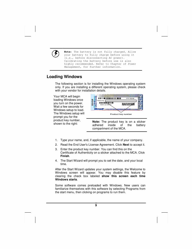
P ro d u c t k e y n u m b e r
Your MCA will begin loading Windows once you turn on the power. Wait a few seconds for Windows setup to load. The Windows setup will prompt you for the product key number, shown to the right:
Note: The product key is on a sticker adhered inside of the battery compartment of the MCA.
1. Type your name, and, if applicable, the name of your company.
2. Read the End User's License Agreement. Click Next to accept it.
3. Enter the product key number. You can find this on the Certificate of Authenticity on a sticker attached to the MCA. Click Finish.
4. The Start Wizard will prompt you to set the date, and your local time.
After the Start Wizard updates your system settings, the Welcome to Windows screen will appear. You may disable this feature by clearing the check box labeled show this screen each time Windows starts.
Some software comes preloaded with Windows. New users can familiarize themselves with this software by selecting Programs from the start menu, then clicking on programs to run them.
10
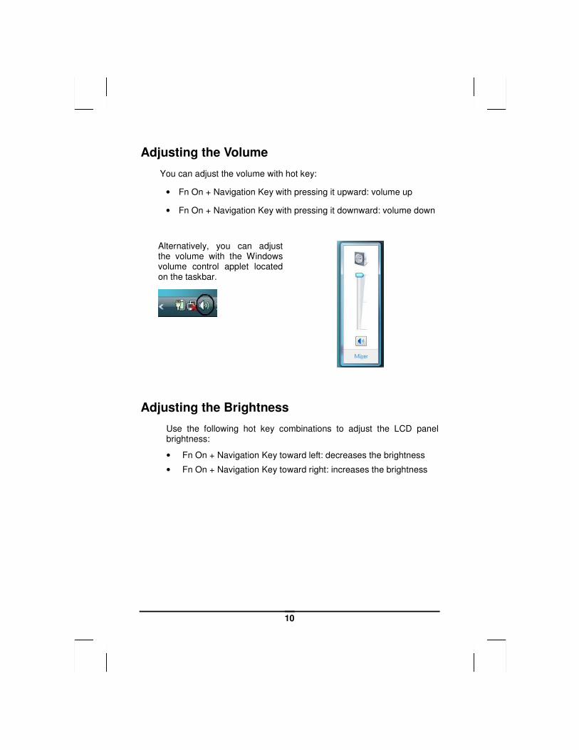
Adjusting the Volume
You can adjust the volume with hot key:
• Fn On + Navigation Key with pressing it upward: volume up
• Fn On + Navigation Key with pressing it downward: volume down
Alternatively, you can adjust the volume with the Windows volume control applet located on the taskbar.
Adjusting the Brightness
Use the following hot key combinations to adjust the LCD panel brightness:
• Fn On + Navigation Key toward left: decreases the brightness
• Fn On + Navigation Key toward right: increases the brightness
11
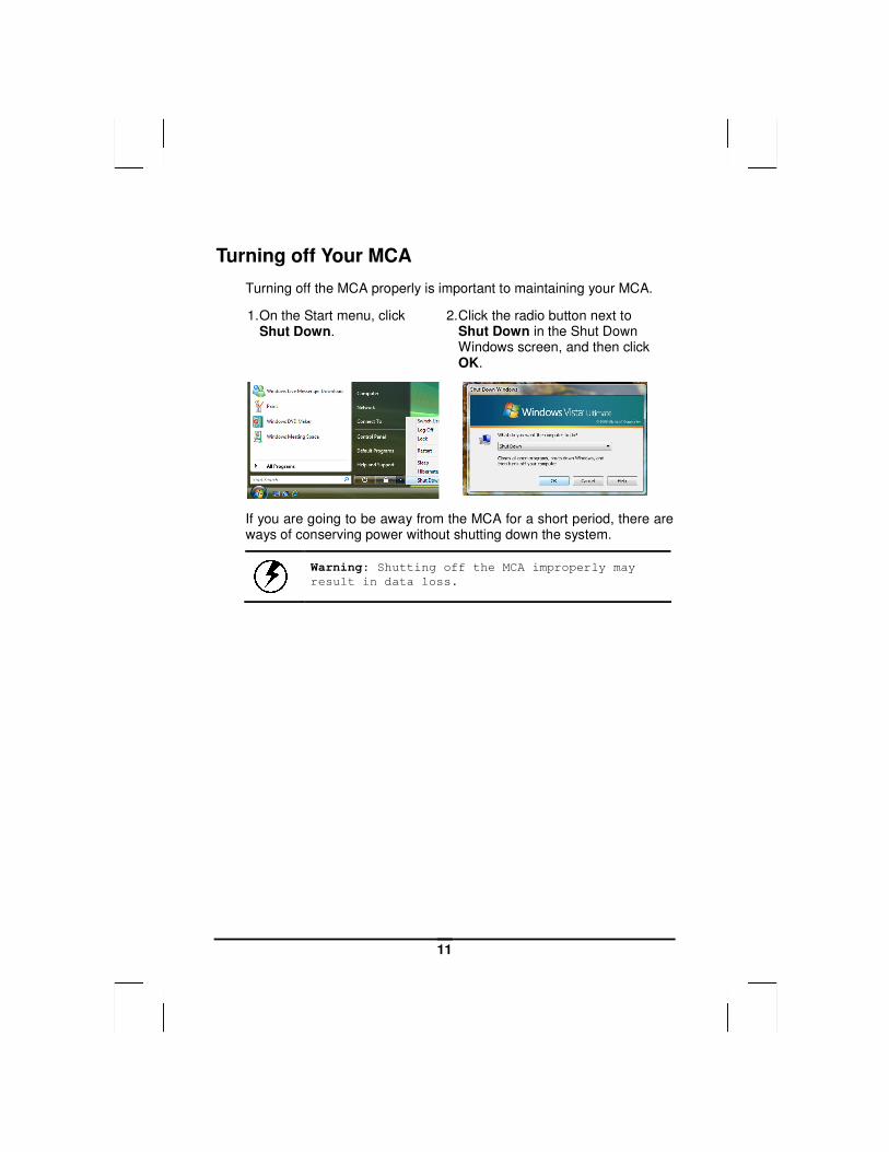
Turning off Your MCA
Turning off the MCA properly is important to maintaining your MCA.
1. On the Start menu, click Shut Down.
2. Click the radio button next to Shut Down in the Shut Down Windows screen, and then click OK.
If you are going to be away from the MCA for a short period, there are ways of conserving power without shutting down the system.
Warning: Shutting off the MCA improperly may
result in data loss.

CChhaapptteerr 22
GGeettttiinngg SSttaarrtteedd
13
Hardware and Software
This chapter introduces the different components and controls of your MCA, including the hardware components, the software, and the audio and video systems.
Getting Started Before you begin using your MCA, read this chapter to familiarize yourself with the main components installed in the system.
14
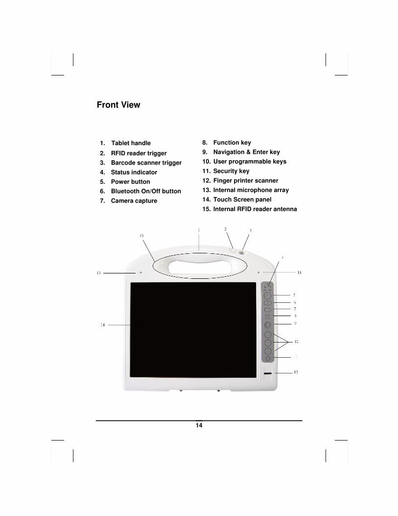
Front View
1. Tablet handle
2. RFID reader trigger
3. Barcode scanner trigger
4. Status indicator
5. Power button
6. Bluetooth On/Off button
7. Camera capture
8. Function key
9. Navigation & Enter key
10. User programmable keys
11. Security key
12. Finger printer scanner
13. Internal microphone array
14. Touch Screen panel
15. Internal RFID reader antenna
15
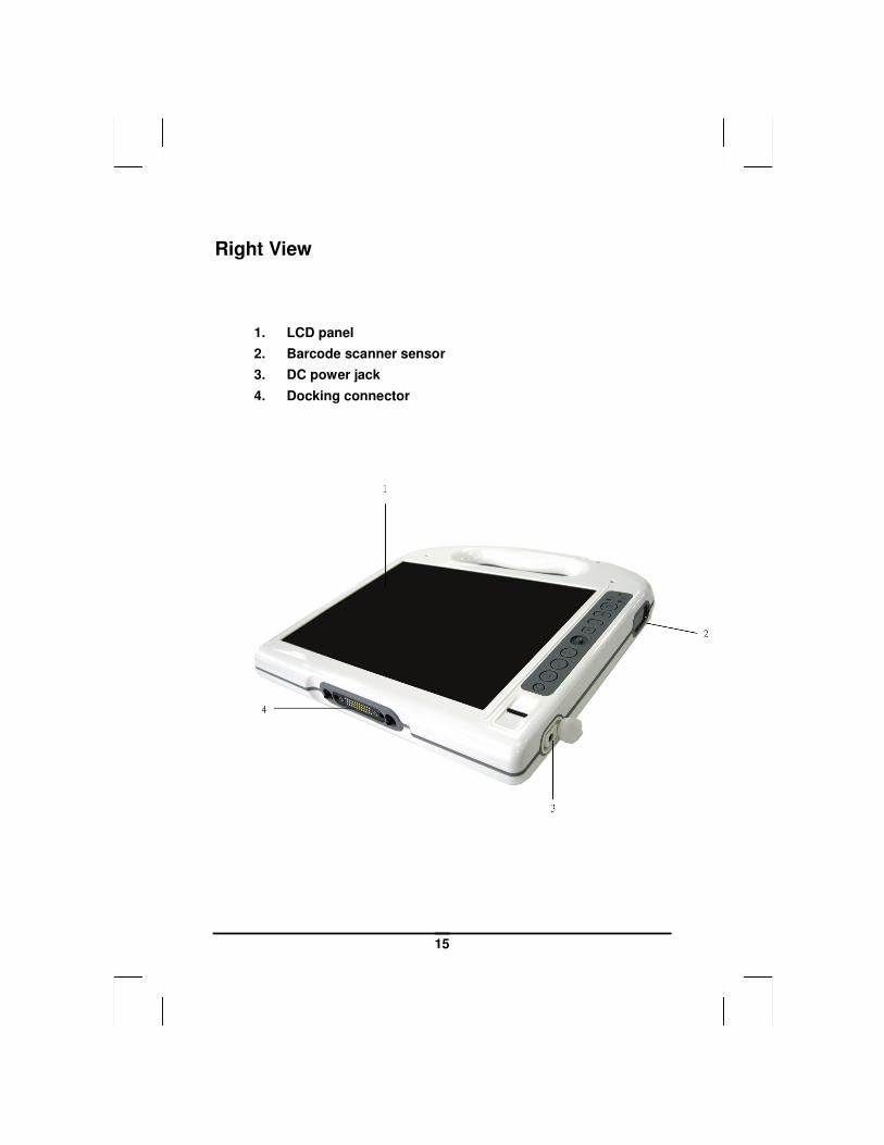
Right View
1. LCD panel
2. Barcode scanner sensor
3. DC power jack
4. Docking connector
16
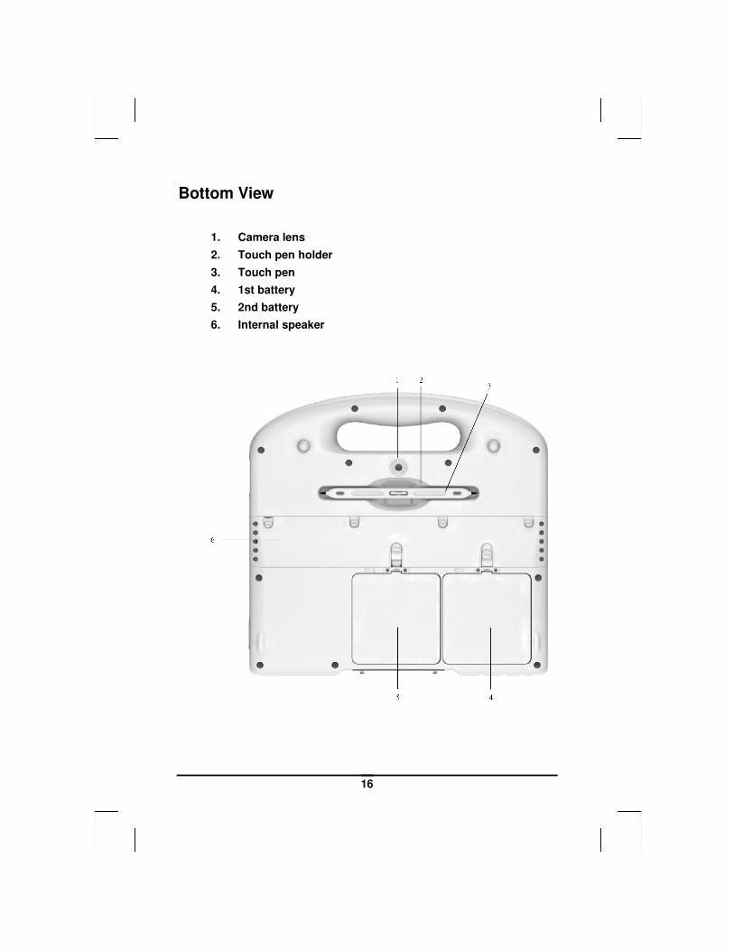
Bottom View
1. Camera lens
2. Touch pen holder
3. Touch pen
4. 1st battery
5. 2nd battery
6. Internal speaker
17
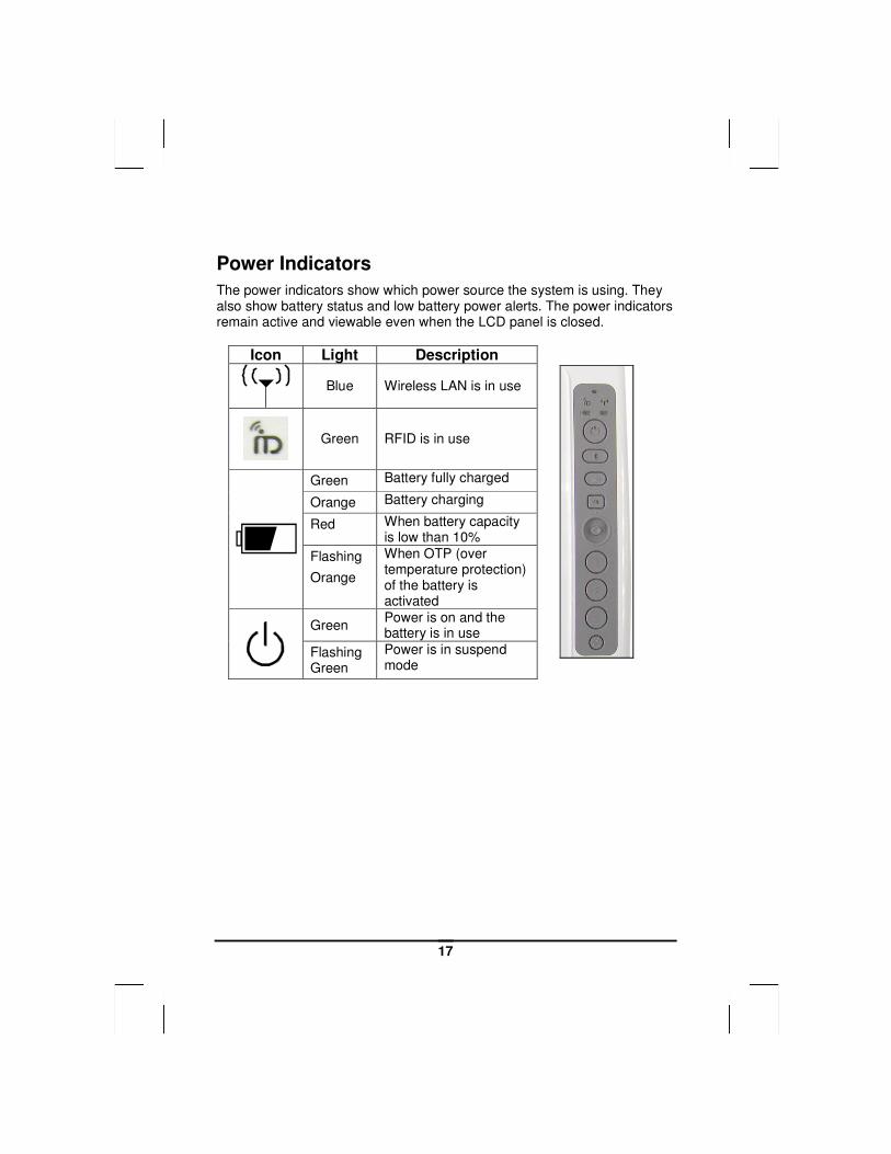
Power Indicators
The power indicators show which power source the system is using. They also show battery status and low battery power alerts. The power indicators remain active and viewable even when the LCD panel is closed.
Icon Light Description
Blue Wireless LAN is in use
Green RFID is in use
Green Battery fully charged
Orange Battery charging
Red When battery capacity is low than 10%
Flashing
Orange
When OTP (over temperature protection) of the battery is activated
Green Power is on and the battery is in use
Flashing Green
Power is in suspend mode
18
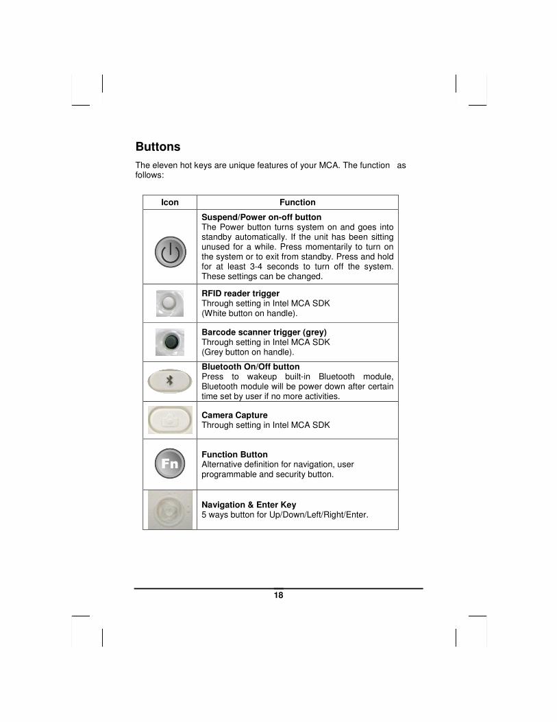
Buttons
The eleven hot keys are unique features of your MCA. The function as follows:
Icon Function
Suspend/Power on-off button The Power button turns system on and goes into standby automatically. If the unit has been sitting unused for a while. Press momentarily to turn on the system or to exit from standby. Press and hold for at least 3-4 seconds to turn off the system. These settings can be changed.
RFID reader trigger Through setting in Intel MCA SDK (White button on handle).
Barcode scanner trigger (grey) Through setting in Intel MCA SDK (Grey button on handle).
Bluetooth On/Off button Press to wakeup built-in Bluetooth module, Bluetooth module will be power down after certain time set by user if no more activities.
Camera Capture Through setting in Intel MCA SDK
Function Button Alternative definition for navigation, user programmable and security button.
Navigation & Enter Key 5 ways button for Up/Down/Left/Right/Enter.
19
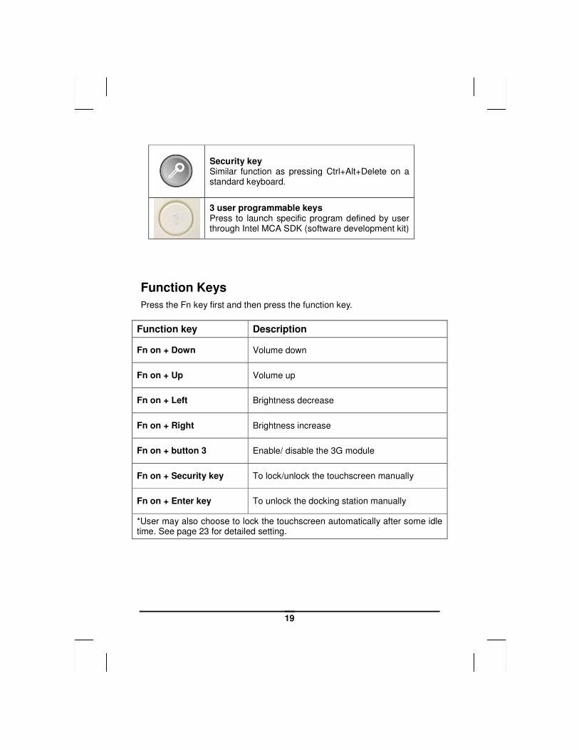
Security key Similar function as pressing Ctrl+Alt+Delete on a standard keyboard.
3 user programmable keys Press to launch specific program defined by user through Intel MCA SDK (software development kit)
Function Keys
Press the Fn key first and then press the function key.
Function key Description
Fn on + Down Volume down
Fn on + Up Volume up
Fn on + Left Brightness decrease
Fn on + Right Brightness increase
Fn on + button 3 Enable/ disable the 3G module
Fn on + Security key To lock/unlock the touchscreen manually
Fn on + Enter key To unlock the docking station manually
*User may also choose to lock the touchscreen automatically after some idle time. See page 23 for detailed setting.
20
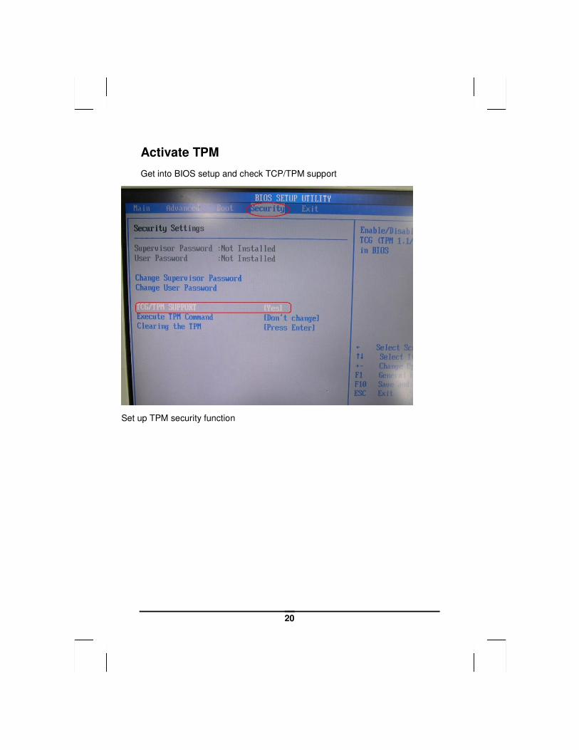
Activate TPM
Get into BIOS setup and check TCP/TPM support
Set up TPM security function

21
22
23
24
25
26
27
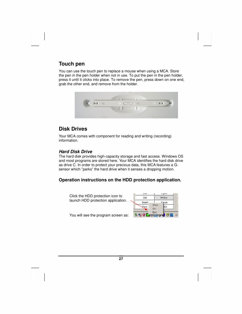
Touch pen
You can use the touch pen to replace a mouse when using a MCA. Store the pen in the pen holder when not in use. To put the pen in the pen holder, press it until it clicks into place. To remove the pen, press down on one end, grab the other end, and remove from the holder.
Disk Drives
Your MCA comes with component for reading and writing (recording) information.
Hard Disk Drive The hard disk provides high-capacity storage and fast access. Windows OS and most programs are stored here. Your MCA identifies the hard disk drive as drive C. In order to protect your precious data, this MCA features a G-sensor which ”parks” the hard drive when it senses a dropping motion.
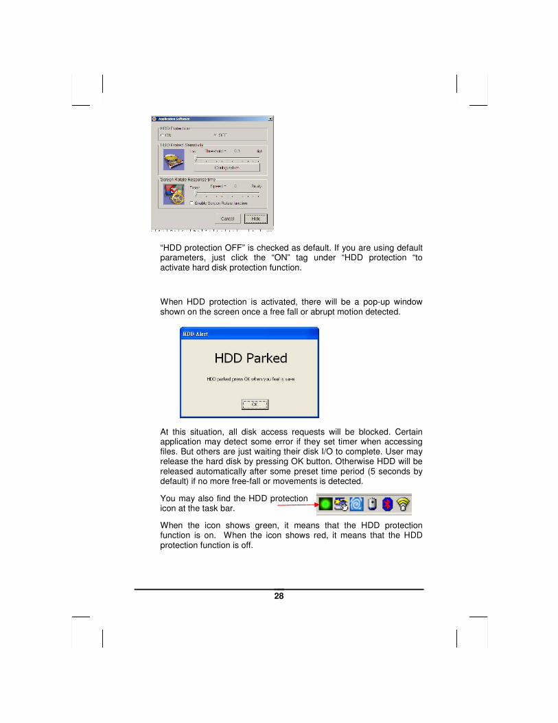
Operation instructions on the HDD protection application.
Click the HDD protection icon to launch HDD protection application.
You will see the program screen as:
28
“HDD protection OFF” is checked as default. If you are using default parameters, just click the “ON” tag under “HDD protection “to activate hard disk protection function.
When HDD protection is activated, there will be a pop-up window shown on the screen once a free fall or abrupt motion detected.
At this situation, all disk access requests will be blocked. Certain application may detect some error if they set timer when accessing files. But others are just waiting their disk I/O to complete. User may release the hard disk by pressing OK button. Otherwise HDD will be released automatically after some preset time period (5 seconds by default) if no more free-fall or movements is detected.
You may also find the HDD protection icon at the task bar.
When the icon shows green, it means that the HDD protection function is on. When the icon shows red, it means that the HDD protection function is off.
29
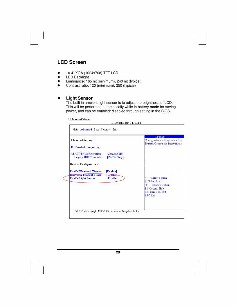
LCD Screen � 10.4” XGA (1024x768) TFT LCD � LED Backlight � Luminance: 165 nit (minimum), 240 nit (typical) � Contrast ratio: 120 (minimum), 250 (typical)
� Light Sensor The built in ambient light sensor is to adjust the brightness of LCD. This will be performed automatically while in battery mode for saving power, and can be enabled/ disabled through setting in the BIOS.
30
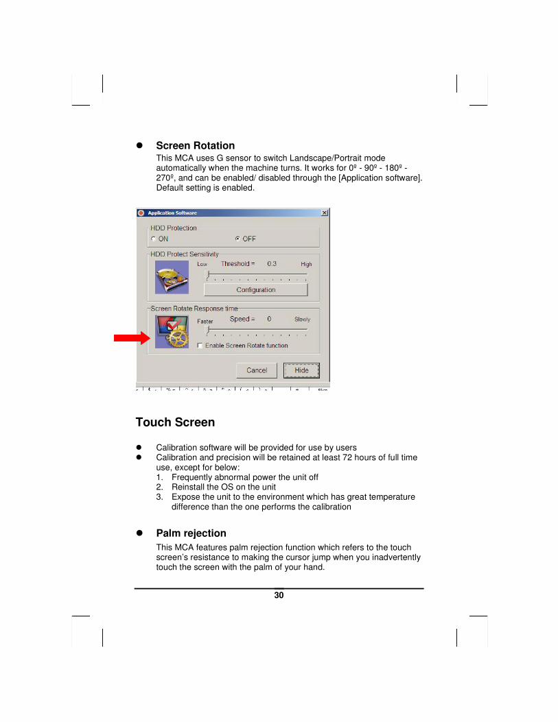
� Screen Rotation This MCA uses G sensor to switch Landscape/Portrait mode automatically when the machine turns. It works for 0º - 90º - 180º - 270º, and can be enabled/ disabled through the [Application software]. Default setting is enabled.
Touch Screen � Calibration software will be provided for use by users � Calibration and precision will be retained at least 72 hours of full time
use, except for below: 1. Frequently abnormal power the unit off 2. Reinstall the OS on the unit 3. Expose the unit to the environment which has great temperature
difference than the one performs the calibration
� Palm rejection
This MCA features palm rejection function which refers to the touch screen’s resistance to making the cursor jump when you inadvertently touch the screen with the palm of your hand.
31
� To lock/unlock the touch screen
To lock: 1. Manually (FN + SAS key)
2. Automatically (after some idle time presetting by user)
To unlock: Manually (FN + SAS key)
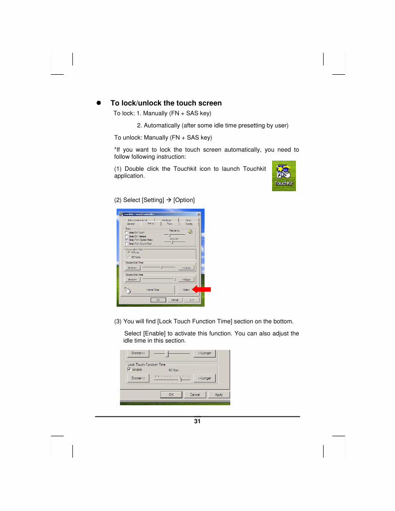
*If you want to lock the touch screen automatically, you need to follow following instruction:
(1) Double click the Touchkit icon to launch Touchkit application.
(2) Select [Setting] � [Option]
(3) You will find [Lock Touch Function Time] section on the bottom.
Select [Enable] to activate this function. You can also adjust the idle time in this section.
32
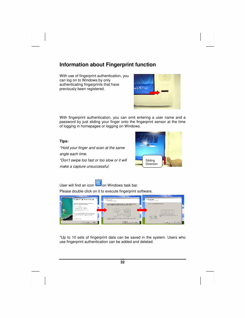
Information about Fingerprint function With use of fingerprint authentication, you can log on to Windows by only authenticating fingerprints that have previously been registered.
With fingerprint authentication, you can omit entering a user name and a password by just sliding your finger onto the fingerprint sensor at the time of logging in homepages or logging on Windows.
Tips:
*Hold your finger and scan at the same
angle each time.
*Don’t swipe too fast or too slow or it will
make a capture unsuccessful.
User will find an icon on Windows task bar.
Please double click on it to execute fingerprint software.
*Up to 10 sets of fingerprint data can be saved in the system. Users who use fingerprint authentication can be added and deleted.
Sliding Direction
33
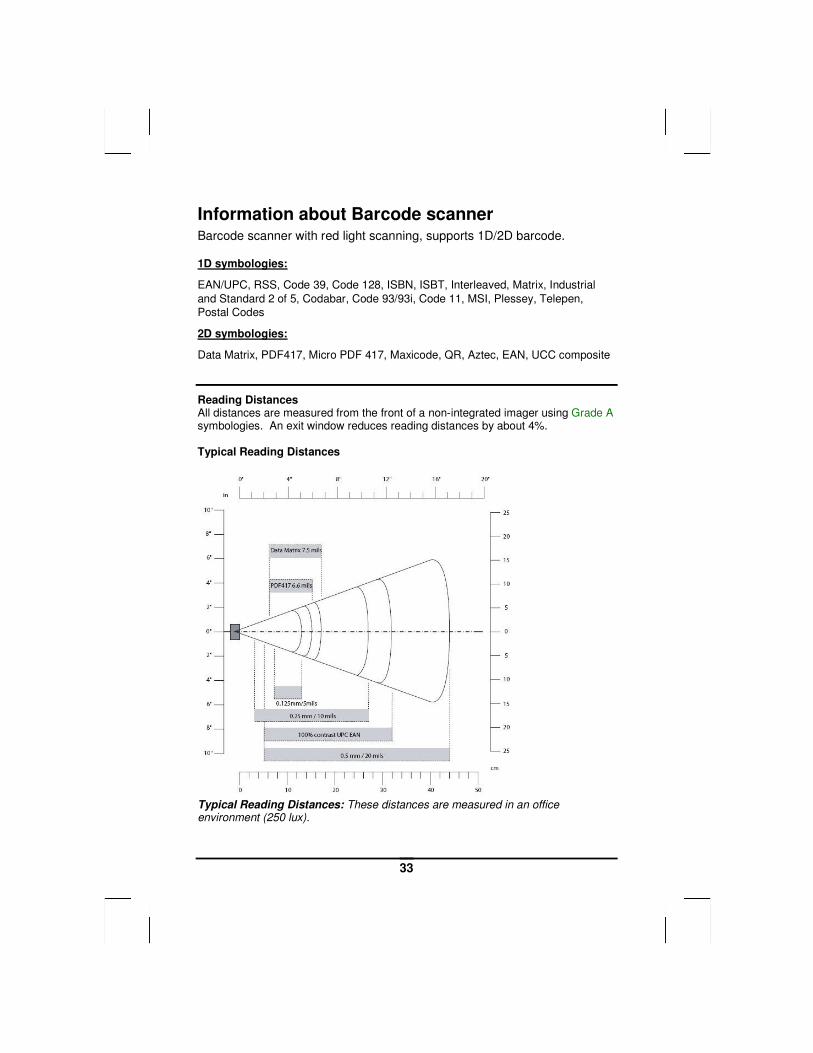
Information about Barcode scanner Barcode scanner with red light scanning, supports 1D/2D barcode. 1D symbologies:
EAN/UPC, RSS, Code 39, Code 128, ISBN, ISBT, Interleaved, Matrix, Industrial
and Standard 2 of 5, Codabar, Code 93/93i, Code 11, MSI, Plessey, Telepen,
Postal Codes
2D symbologies:
Data Matrix, PDF417, Micro PDF 417, Maxicode, QR, Aztec, EAN, UCC composite
Reading Distances All distances are measured from the front of a non-integrated imager using Grade A symbologies. An exit window reduces reading distances by about 4%. Typical Reading Distances
Typical Reading Distances: These distances are measured in an office environment (250 lux).
34
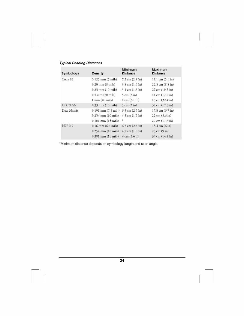
Typical Reading Distances
*Minimum distance depends on symbology length and scan angle.
35
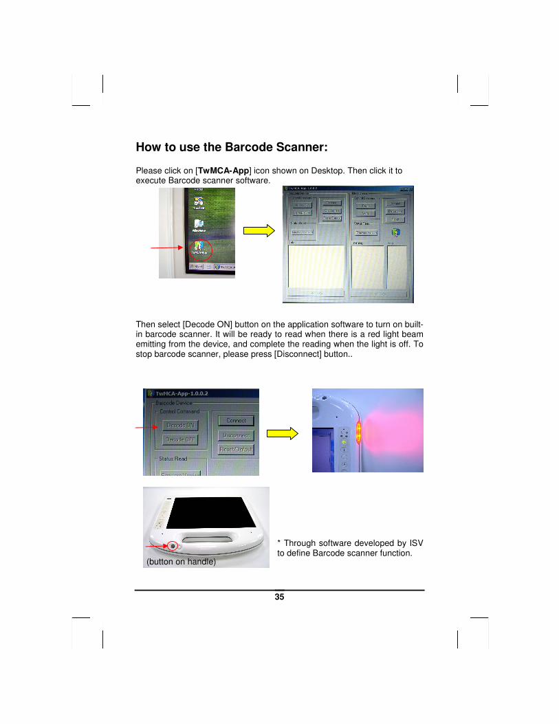
How to use the Barcode Scanner: Please click on [TwMCA-App] icon shown on Desktop. Then click it to execute Barcode scanner software.
Then select [Decode ON] button on the application software to turn on built-in barcode scanner. It will be ready to read when there is a red light beam emitting from the device, and complete the reading when the light is off. To stop barcode scanner, please press [Disconnect] button..
* Through software developed by ISV to define Barcode scanner function.
(button on handle)
36
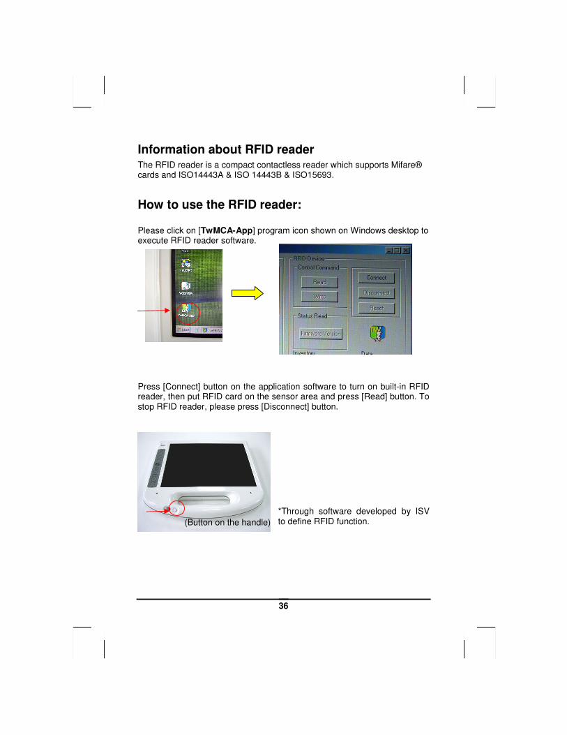
Information about RFID reader
The RFID reader is a compact contactless reader which supports Mifare® cards and ISO14443A & ISO 14443B & ISO15693.
How to use the RFID reader: Please click on [TwMCA-App] program icon shown on Windows desktop to execute RFID reader software.
Press [Connect] button on the application software to turn on built-in RFID reader, then put RFID card on the sensor area and press [Read] button. To stop RFID reader, please press [Disconnect] button.
*Through software developed by ISV to define RFID function.
(Button on the handle)
37
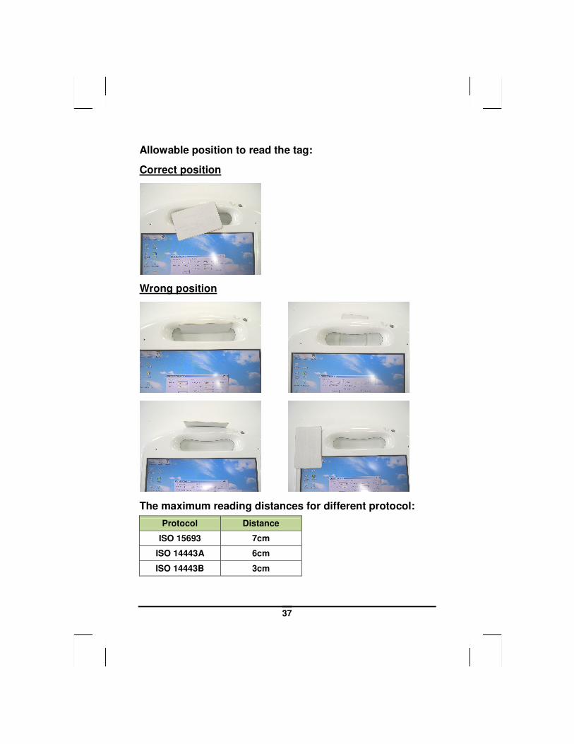
Allowable position to read the tag:
Correct position
Wrong position
The maximum reading distances for different protocol:
Protocol Distance
ISO 15693 7cm
ISO 14443A 6cm
ISO 14443B 3cm
38
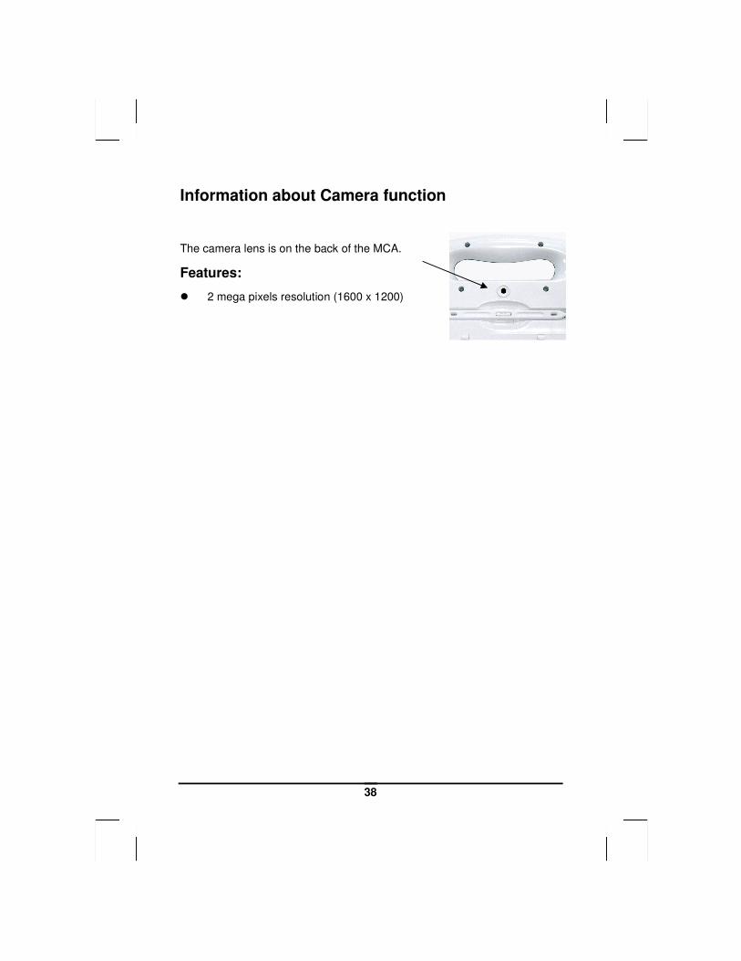
Information about Camera function
The camera lens is on the back of the MCA.
Features:
� 2 mega pixels resolution (1600 x 1200)
39
Communication Components
This system includes built-in Wireless LAN, Bluetooth and 3G functions:
Built-in Wireless Local Area Network
The built-in Wireless Local Area Network (WLAN) interface card can
provide a quick access without using cables for the connection to the
network equipments. The interface card adopts the IEEE 802.11 a/b/g/n
protocol and uses the 2.4/5 GHz ISM electric wave frequency band as
the transmission interface to set up the communications between the
host computer and other computers.
The way of processing communications through the WLAN interface
card is the same as that through Ethernet interface card. The
“Configuration Tool” is a Window application program. If users have a
computer equipped with the WLAN interface card, then users can use
it to set up the interface card and show the current configuration and
status. Note: Contact your distributor for the information of upgrading the wireless local area network.
40
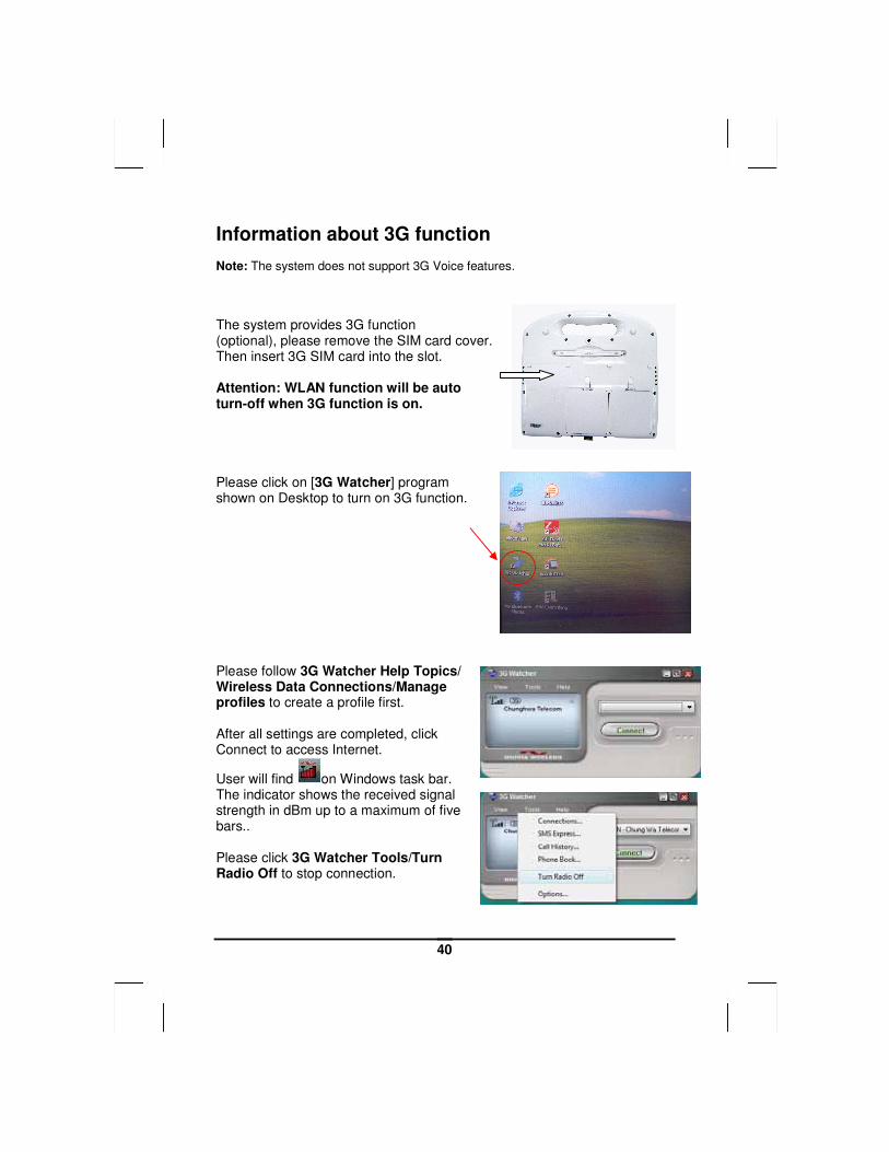
Information about 3G function Note: The system does not support 3G Voice features.
The system provides 3G function (optional), please remove the SIM card cover. Then insert 3G SIM card into the slot. Attention: WLAN function will be auto turn-off when 3G function is on. Please click on [3G Watcher] program shown on Desktop to turn on 3G function. Please follow 3G Watcher Help Topics/ Wireless Data Connections/Manage profiles to create a profile first. After all settings are completed, click Connect to access Internet.
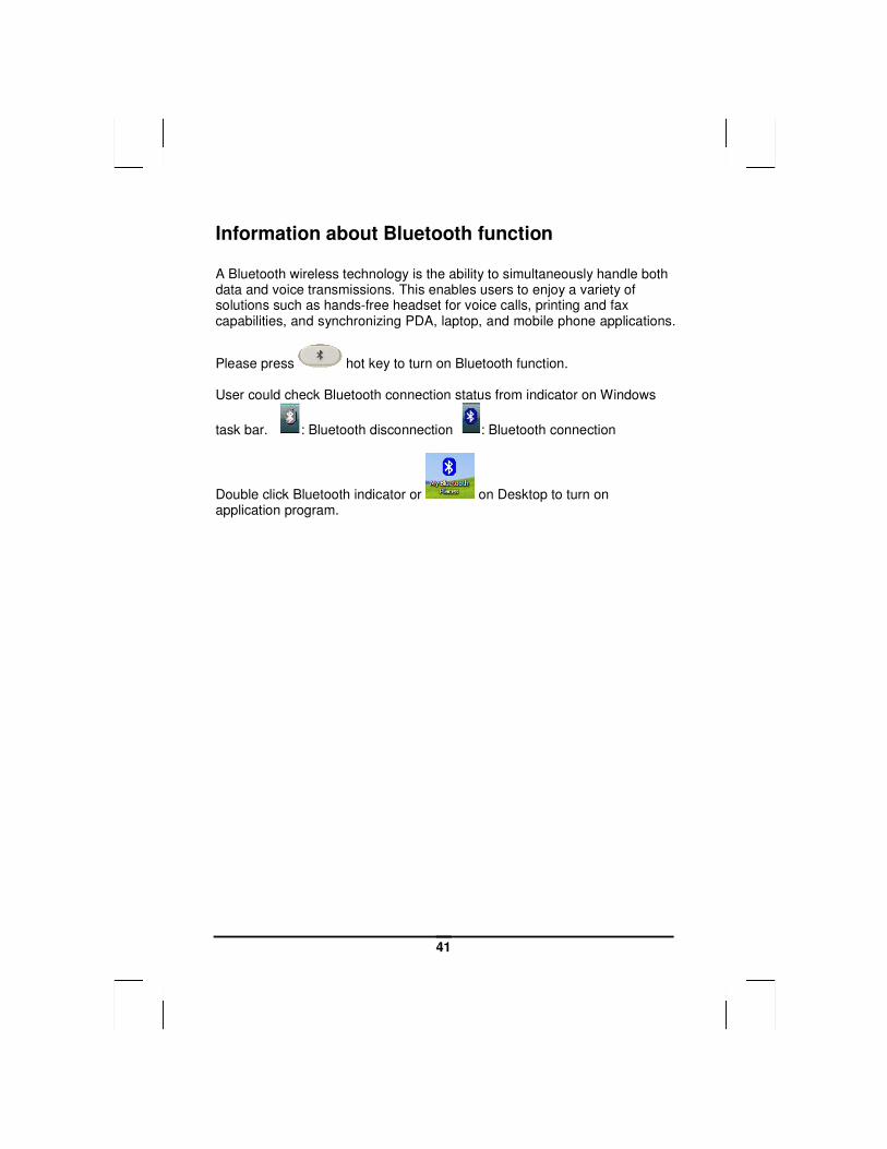
User will find on Windows task bar. The indicator shows the received signal strength in dBm up to a maximum of five bars.. Please click 3G Watcher Tools/Turn Radio Off to stop connection.
41
Information about Bluetooth function A Bluetooth wireless technology is the ability to simultaneously handle both data and voice transmissions. This enables users to enjoy a variety of solutions such as hands-free headset for voice calls, printing and fax capabilities, and synchronizing PDA, laptop, and mobile phone applications.
Please press hot key to turn on Bluetooth function. User could check Bluetooth connection status from indicator on Windows
task bar. : Bluetooth disconnection : Bluetooth connection
Double click Bluetooth indicator or on Desktop to turn on application program.

CChhaapptteerr 33
MMaakkiinngg CCoonnnneeccttiioonnss
36
Making Connections
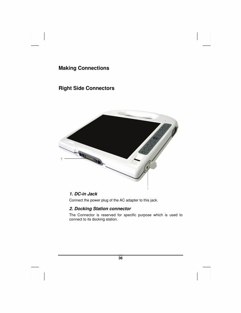
Right Side Connectors
1. DC-in Jack
Connect the power plug of the AC adapter to this jack.
2. Docking Station connector
The Connector is reserved for specific purpose which is used to connect to its docking station.
CChhaapptteerr 44
PPoowweerr MMaannaaggeemmeenntt
38
Power Management
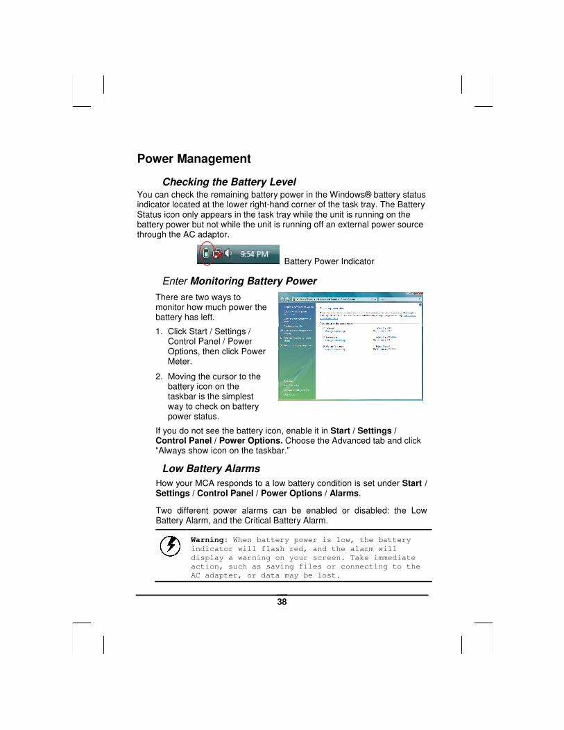
Checking the Battery Level You can check the remaining battery power in the Windows® battery status indicator located at the lower right-hand corner of the task tray. The Battery Status icon only appears in the task tray while the unit is running on the battery power but not while the unit is running off an external power source through the AC adaptor.
Battery Power Indicator
Enter Monitoring Battery Power
There are two ways to monitor how much power the battery has left.
1. Click Start / Settings / Control Panel / Power Options, then click Power Meter.
2. Moving the cursor to the battery icon on the taskbar is the simplest way to check on battery power status.
If you do not see the battery icon, enable it in Start / Settings / Control Panel / Power Options. Choose the Advanced tab and click “Always show icon on the taskbar.”
Low Battery Alarms
How your MCA responds to a low battery condition is set under Start / Settings / Control Panel / Power Options / Alarms.
Two different power alarms can be enabled or disabled: the Low Battery Alarm, and the Critical Battery Alarm.
Warning: When battery power is low, the battery
indicator will flash red, and the alarm will
display a warning on your screen. Take immediate
action, such as saving files or connecting to the
AC adapter, or data may be lost.
39
Battery Charging
When you use the AC adapter to connect your MCA to a power outlet, the internal battery will automatically begin to recharge (get charged first with battery 1, then goes to battery 2 when battery 1 is fully charged, and the MCA is powered by the AC adaptor.) While the battery is charging, the Battery Charge icon on the Indicator panel will be active after 6~12 seconds. When the battery is fully charged, the Battery Charge icon will turn off.
If your MCA is system off, a fully discharged battery will take about 2 hours to recharge. If your MCA is turned on and is not in suspend mode, it twill take about 2~3 hours to recharge the battery. Refer to the following table:
Charging
System On
(Under Screen Saver Mode) 2~3 hours
System Off (suspend to RAM) ~2 hours
Note: One fully charged Li-Ion battery can run the
MCA for approximately 2.25 hours.
When to Replace the Battery
Over time, the battery's capacity gradually decreases. We recommend that you replace your battery when you notice that it begins to store significantly less charge.
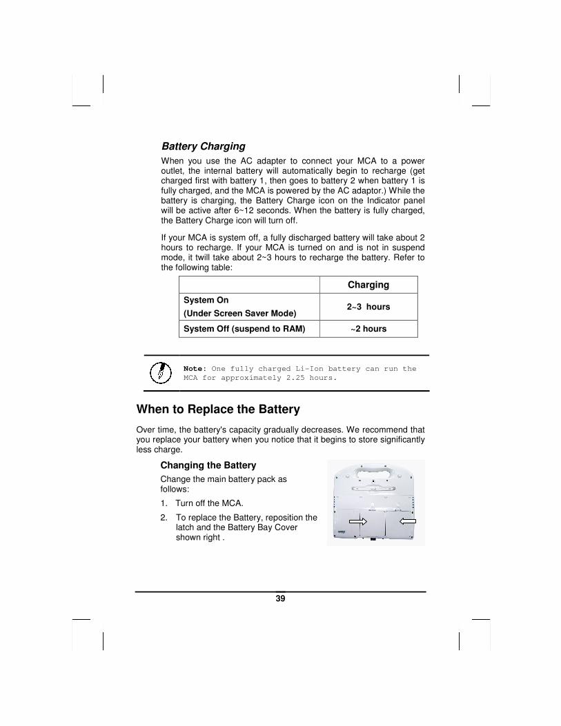
Changing the Battery
Change the main battery pack as follows:
1. Turn off the MCA.
2. To replace the Battery, reposition the latch and the Battery Bay Cover shown right .
40
3. Make sure the replacement battery is properly orientated. Then insert the battery into the battery compartment. Check that the latch locks back into position.
Heat Considerations
The MCA processor has been specially designed to consume little power, and generates very little heat. However, working in a hot environment, or working for long periods may raise the temperature. If the temperature continues to rise, processor activity will be reduced. You may notice a slight loss of performance when this happens.
41
Chapter 5
DDoocckkiinngg SSttaattiioonn
CCoonnnneeccttoorrss
42
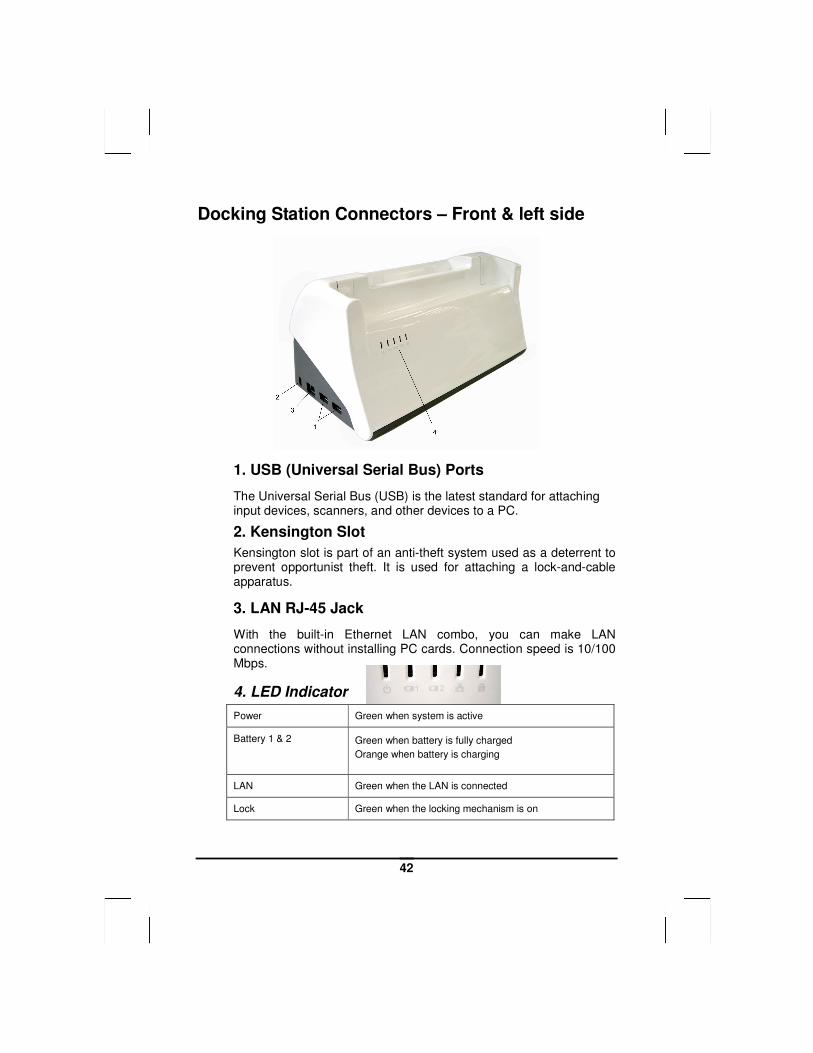
Docking Station Connectors – Front & left side
1. USB (Universal Serial Bus) Ports
The Universal Serial Bus (USB) is the latest standard for attaching input devices, scanners, and other devices to a PC.
2. Kensington Slot
Kensington slot is part of an anti-theft system used as a deterrent to prevent opportunist theft. It is used for attaching a lock-and-cable apparatus.
3. LAN RJ-45 Jack
With the built-in Ethernet LAN combo, you can make LAN connections without installing PC cards. Connection speed is 10/100 Mbps.
4. LED Indicator
Power Green when system is active
Battery 1 & 2 Green when battery is fully charged
Orange when battery is charging
LAN Green when the LAN is connected
Lock Green when the locking mechanism is on
43
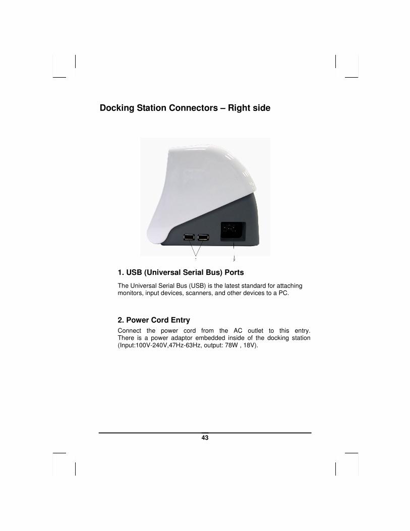
Docking Station Connectors – Right side
1. USB (Universal Serial Bus) Ports
The Universal Serial Bus (USB) is the latest standard for attaching monitors, input devices, scanners, and other devices to a PC.
2. Power Cord Entry
Connect the power cord from the AC outlet to this entry. There is a power adaptor embedded inside of the docking station (Input:100V-240V,47Hz-63Hz, output: 78W , 18V).
44
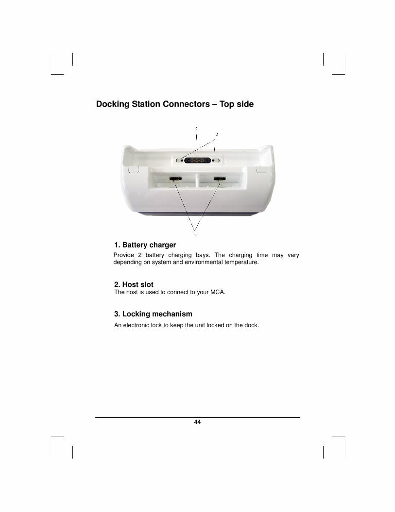
Docking Station Connectors – Top side
1. Battery charger
Provide 2 battery charging bays. The charging time may vary depending on system and environmental temperature.
2. Host slot The host is used to connect to your MCA.
3. Locking mechanism
An electronic lock to keep the unit locked on the dock.
45
Mechanical Specification
Mounting:
An optional bracket (VESA standard, hole pattern 75 x 75 mm) is available when there is need to mount the docking station for different purposes.
Tilt: To provide an optimal viewing performance while user is in different operating position, this docking station is capable of adjusting the tilt angle, and it ranges from 5° forwardly, and 25° backwardly.
AAppppeennddiixx AA
SSttaatteemmeennttss
47
Statements
Federal Communications Commission Statement
This equipment has been tested and found to comply with the limits for a Class B digital device, pursuant to Part 15 of the FCC Rules. These limits are designed to provide reasonable protection against harmful interference in a residential installation. This equipment generates, uses, and can radiate radio frequency energy and, if not installed and used in accordance with the instructions, may cause harmful interference to radio communications. However, there is no guarantee that interference will not occur in a particular installation. If this equipment does cause harmful interference to radio or television reception, which can be determined by turning the equipment off and on, the user is encouraged to try to correct the interference by one or more of the following measures:
1. Reorient or relocate the receiving antenna.
2. Increase the separation between the equipment and the receiver.
3. Connect the equipment into an outlet on a circuit different from that to which the receiver is connected.
4. Consult the dealer or an experienced radio/TV technician for help.
Shielded interconnect cables and shielded AC power cable must be employed with this equipment to insure compliance with the pertinent RF emission limits governing this device. Changes or modifications not expressly approved by the system's manufacturer could void the user's authority to operate the equipment.
CAUTION
Any changes or modifications not expressly approved by the party responsible for compliance could void the user's authority to operate the equipment.
48
RF exposure warning
The equipment complies with FCC RF exposure limits set forth foran uncontrolled environment. The equipment must not be co-located or operating in conjunction with any other antenna or transmitter.
Declaration of Conformity
This device complies with part 15 of the FCC rules. Operation is subject to the following conditions:
• This device may not cause harmful interference
• This device must accept any interference received, including interference that may cause undesired operation.
According to FCC 15.407(e), the device is intended to operate in the frequency band of 5.15GHz to 5.25GHz under all conditions of normal operation. Normal operation of this device is restricted to indoor used environment only
European Notice
CE Declaration of Conformity
For the following equipment: Tablet built-in 802.11a/b/g/n WLAN module
Is herewith confirmed to comply with the requirements set out in the Council Directive on the Approximation of the Laws of the Member States relating to Electromagnetic Compatibility (89/336/EEC), Low-voltage Directive (73/23/EEC) and the Amendment Directive (93/68/EEC), the procedures given in European Council Directive 99/5/EC and 89/3360EEC.
The equipment was passed. The test was performed according to the following European standards:
• EN 300 328 V.1.4.1 (2003-04)
49
• EN 301 489-1 V.1.3.1 (2001-09) / EN 301 489-17 V.1.1.1 (2000-09)
• EN 301 893 V.1.2.2 (2003-06)
• EN 50371: 2002
• EN 60950: 2000
Standard Inspection Bureau for Japan
Authentication sign of the Standard Inspection Bureau for Japan
Standard Inspection Bureau for Korea
Authentication sign of the Standard Inspection Bureau for Korea
Standard Inspection Bureau for China
Authentication sign of the Standard Inspection Bureau for China.

50
Standard Inspection Bureau for Taiwan
Authentication sign of the Standard Inspection Bureau for Taiwan.
Regulatory statement (R&TTE / WLAN IEEE 802.11b & 802.11g)
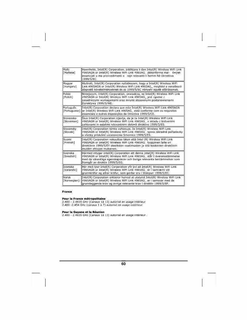
European standards dictate maximum radiated transmit power of 100mW EIRP and frequency range 2.400-2.4835GHz; In France, the equipment must be restricted to the 2.4465-2.4835GHz frequency range and must be restricted to indoor use.
Safety Compliance
Safety for Canada
c-UL/CSA C22.2 No 60950-1
51
Safety for Korea
KETI (eK) : for adaptor only
Battery Disposal
THIS PRODUCT CONTAINS A LITHIUM-ION OR NICKEL-METAL HYDRIDE BATTERY. IT MUST BE DISPOSED OF PROPERLY. CONTACT LOCAL ENVIRONMENTAL AGENCIES FOR INFORMATION ON RECYCLING AND DISPOSAL PLANS IN YOUR AREA.
CAUTION FOR ADAPTER
THIS MCA IS FOR USE WITH MODEL NO. 0335A2065, 0335C2065, JWM180KA1800F02.
BATTERY CAUTION
DANGER OF EXPLOSION IF BATTERY IS INCORRECTLY REPLACED.
REPLACE ONLY WITH THE SAME OR EQUIVALENT TYPE RECOMMENDED BY THE MANUFACTURER. DISPOSE OF USED BATTERIES ACCORDING TO THE MANUFACTURER'S INSTRUCTIONS.
Regulatory information / Disclaimers
Installation and use of this Wireless LAN device must be in strict accordance with the instructions included in the user documentation provided with the product. Any changes or modifications (including the antennas) made to this device that are not expressly approved by the manufacturer may void the user’s authority to operate the equipment. The manufacturer is not responsible for any radio or television interference caused by unauthorized modification of this device, or the substitution of the connecting cables and equipment
52
other than manufacturer specified. It is the responsibility of the user to correct any interference caused by such unauthorized modification, substitution or attachment. Manufacturer and its authorized resellers or distributors will assume no liability for any damage or violation of government regulations arising from failing to comply with these guidelines.
IMPORTANT NOTE (CO-LOCATION)
FCC RF Radiation Exposure Statement: This equipment complies with FCC RF radiation exposure limits set forth for an uncontrolled environment. This device and its antenna must not be co-located or operating in conjunction with any other antenna or transmitter.
Radio Frequency Interference Requirements
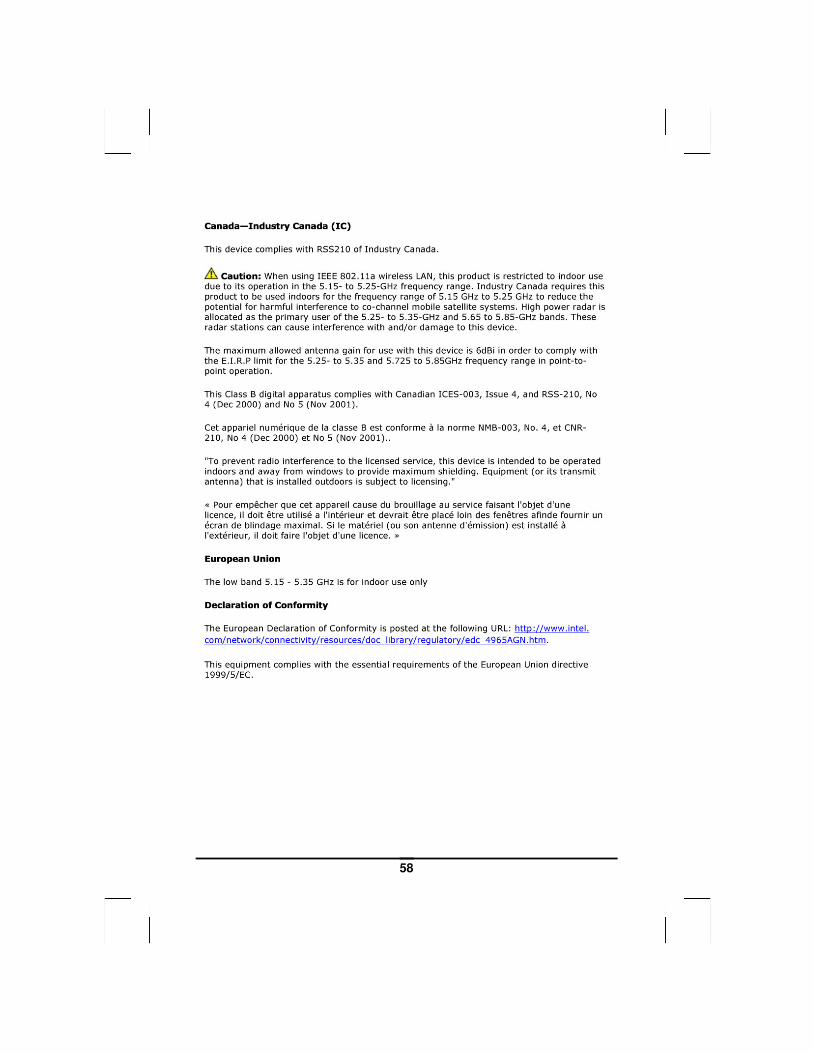
This device is restricted to INDOOR USE due to its operation in the 5.15 to 5.25GHz frequency range. According to FCC 15.407(e), requires this product to be used indoors for the frequency range 5.15 to 5.25GHz to reduce the potential for harmful interference to co-channel of the Mobile Satellite Systems.
High power radars are allocated as primary user of the 5.25 to 5.35GHz and 5.65 to 5.85GHz bands. These radar stations can cause interference with and / or damage this device
SAR Exposure
This device has been tested for compliance with FCC RF Exposure (SAR) limits in typical flat configurations.
In order to comply with SAR limits established in the ANSI C95.1 standards, it is recommended when using a CF card that the integrated antenna is positioned more than 1.5cm from your body or nearby persons during extended periods of operation. If the antenna is positioned less than 1.5cm from the user, it is recommended that the user limit the exposure time.
Max. SAR Measurement (1g)
802.11b: 0.150 W/kg
802.11g: 0.132 W/kg
802.11a(5.2GHz): 1.078 W/kg
802.11a(5.8GHz): 0.728 W/kg
53
WLAN
“To prevent radio interference to the licensed service, this device is intended to be operated indoors and away from windows to provide maximum shielding. Equipment (or its transmit antenna) that is installed outdoors is subject to licensing.”
Please note that the manufacturer must guarantee that it has no Ad-hoc capability for 5250~5350 and 5470~5725 MHz frequency band.
For LPD
“Operation is subject to the following two conditions: (1) this device may not cause interference, and (2) this device must accept any interference, including interference that may cause undesired operation of the device.”
W/detachable antenna
“To reduce potential radio interference to other users, the antenna type and its gain should be so chosen that the equivalent isotropically radiated power (EIRP) is not more than that required for successful communication.”
54
55
56
57
58

59
60
61
62