t03 hitachi
TRANSCRIPT
7/24/2019 t03 hitachi
http://slidepdf.com/reader/full/t03-hitachi 1/104
1HH-3-1
SECTION 3
COMPONENT OPERATION
CONTENTS
Group 1 Pump Device
Outline .....................................................T3-1-1
Main Pump1, 2 .........................................T3-1-2
Regulator .................................................T3-1-6
Pilot Pump..............................................T3-1-22
N Sensor (Engine Speed Sensor)...........T3-1-22
Pump Delivery Pressure Sensor.............T3-1-22
Group 2 Swing Device
Outline .....................................................T3-2-1
Swing Motor .............................................T3-2-2
Swing Parking Brake ................................T3-2-3
Valve Unit.................................................T3-2-4Swing Reduction Gear..............................T3-2-6
Group 3 Control Valve
Outline .....................................................T3-3-1
Hydraulic Circuit .......................................T3-3-6
Flow Combiner Valve..............................T3-3-10
Pump Control Valve................................T3-3-12
Main Relief Valve....................................T3-3-14
Overload Relief Valve .............................T3-3-15
Arm Regenerative Valve .... .... ........ .... .... .T3-3-16
Boom Regenerative Valve ......................T3-3-18
Bucket Regenerative Valve.....................T3-3-20
Arm Anti-Drift Valve (Bottom Side)... .... ...T3-3-22
Arm Anti-Drift Valve (Rod Side) /
Boom Anti-Drift Valve ...........................T3-3-25
Bucket Flow Rate Control Valve .............T3-3-26
Travel Flow Rate Control Valve...............T3-3-28
Bypass Shut-Out Valve...........................T3-3-30
Needle Valve..........................................T3-3-32
Group 4 Pilot Valve
Outline .....................................................T3-4-1
Operation .................................................T3-4-2
Group 5 Travel Device
Outline .....................................................T3-5-1
Travel Reduction Gear..............................T3-5-2
Travel Motor .............................................T3-5-3
Travel Brake Valve ...................................T3-5-6
Travel Motor Swash Angle Control..........T3-5-14
Parking Brake.........................................T3-5-19
Group 6 Others (Upperstructure)Pilot Shut-Off Valve ..................................T3-6-1
Shockless Valve .......................................T3-6-2
Solenoid Valve Unit ..................................T3-6-4
Torque Control Solenoid Valve, Pump 2
Flow Rate Control Solenoid Valve ...........T3-6-6
Pilot Relief Valve ......................................T3-6-8
EC Motor ..................................................T3-6-8
Group 7 Others (Undercarriage)
Swing Bearing ..........................................T3-7-1
Center Joint..............................................T3-7-2
Track Adjuster ..........................................T3-7-3
7/24/2019 t03 hitachi
http://slidepdf.com/reader/full/t03-hitachi 2/104
1HH-3-2
(Blank)
7/24/2019 t03 hitachi
http://slidepdf.com/reader/full/t03-hitachi 3/104
COMPONENT OPERATION / Pump Device
T3-1-1
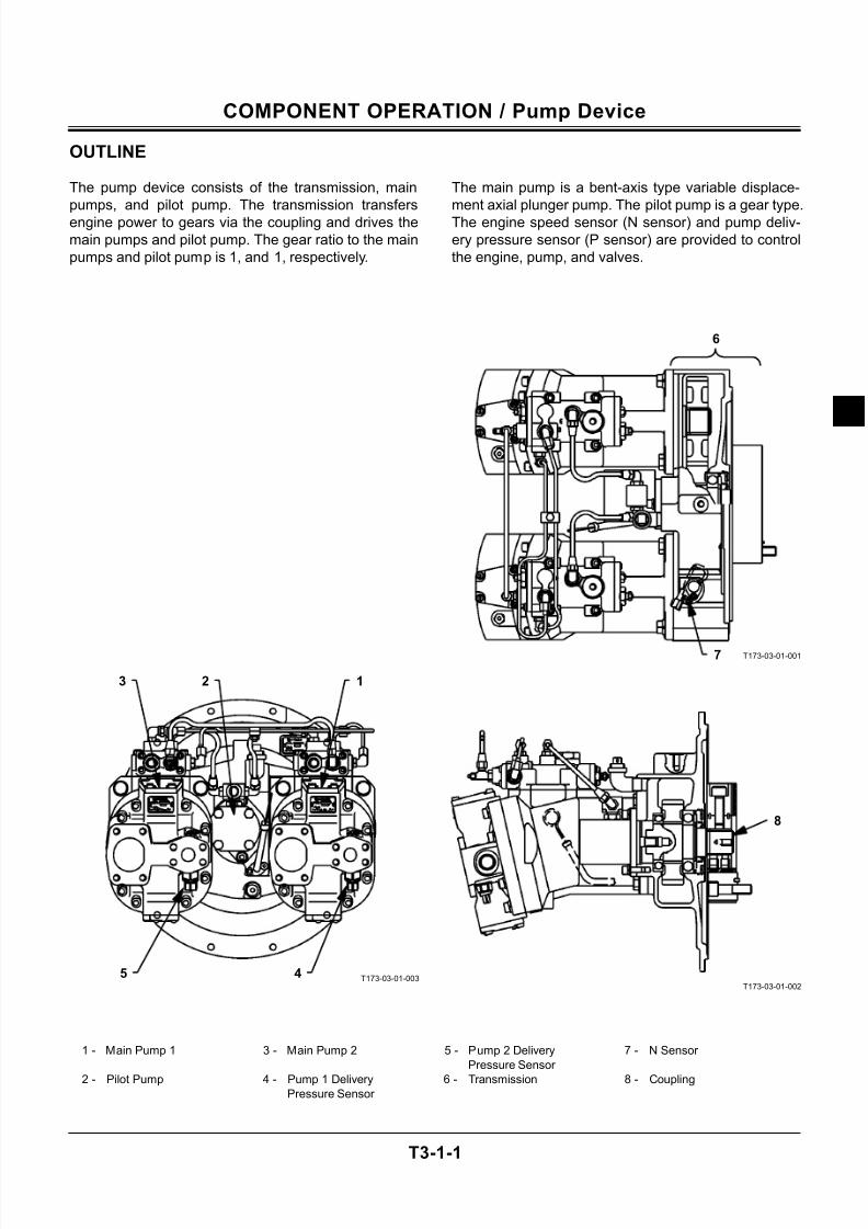
OUTLINE
The pump device consists of the transmission, main
pumps, and pilot pump. The transmission transfers
engine power to gears via the coupling and drives the
main pumps and pilot pump. The gear ratio to the main
pumps and pilot pump is 1, and 1, respectively.
The main pump is a bent-axis type variable displace-
ment axial plunger pump. The pilot pump is a gear type.
The engine speed sensor (N sensor) and pump deliv-
ery pressure sensor (P sensor) are provided to control
the engine, pump, and valves.
T173-03-01-003
T173-03-01-001
T173-03-01-002
1 - Main Pump 1 3 - Main Pump 2 5 - Pump 2 Delivery
Pressure Sensor
7 - N Sensor
2 - Pilot Pump 4 - Pump 1 DeliveryPressure Sensor
6 - Transmission 8 - Coupling
7
6
123
5 4
8
7/24/2019 t03 hitachi
http://slidepdf.com/reader/full/t03-hitachi 4/104
COMPONENT OPERATION / Pump Device
T3-1-2
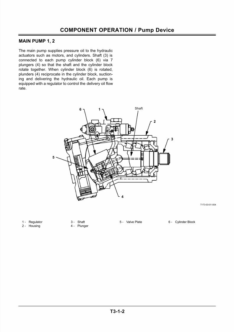
MAIN PUMP 1, 2
The main pump supplies pressure oil to the hydraulic
actuators such as motors, and cylinders. Shaft (3) is
connected to each pump cylinder block (6) via 7
plungers (4) so that the shaft and the cylinder block
rotate together. When cylinder block (6) is rotated,
plunders (4) reciprocate in the cylinder block, suction-
ing and delivering the hydraulic oil. Each pump is
equipped with a regulator to control the delivery oil flow
rate.
T173-03-01-004
1 - Regulator 3 - Shaft 5 - Valve Plate 6 - Cylinder Block
2 - Housing 4 - Plunger
Shaft6 1
2
3
5
4
7/24/2019 t03 hitachi
http://slidepdf.com/reader/full/t03-hitachi 5/104
COMPONENT OPERATION / Pump Device
T3-1-3
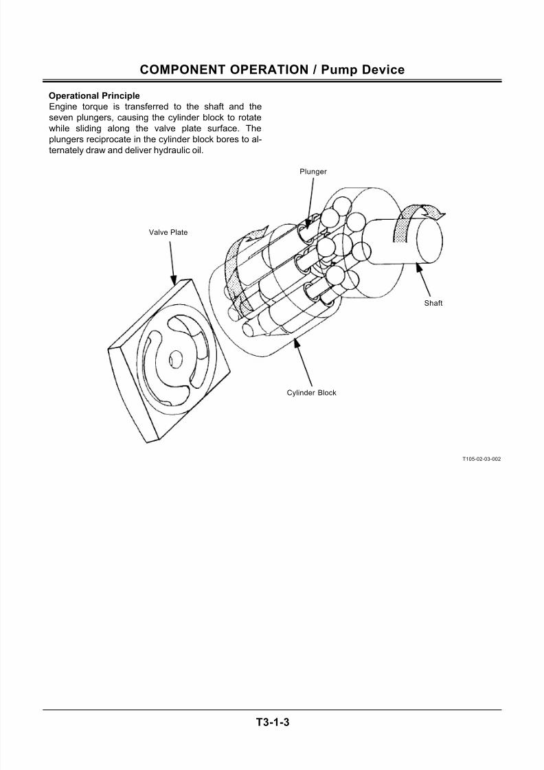
Operational Principle
Engine torque is transferred to the shaft and the
seven plungers, causing the cylinder block to rotate
while sliding along the valve plate surface. The
plungers reciprocate in the cylinder block bores to al-
ternately draw and deliver hydraulic oil.
T105-02-03-002
Plunger
Valve Plate
Shaft
Cylinder Block
7/24/2019 t03 hitachi
http://slidepdf.com/reader/full/t03-hitachi 6/104
COMPONENT OPERATION / Pump Device
T3-1-4
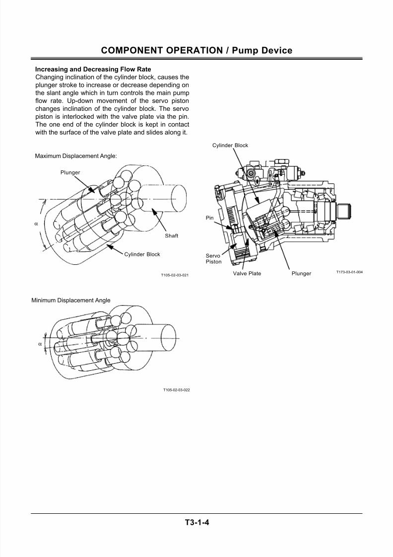
Increasing and Decreasing Flow Rate
Changing inclination of the cylinder block, causes the
plunger stroke to increase or decrease depending on
the slant angle which in turn controls the main pump
flow rate. Up-down movement of the servo piston
changes inclination of the cylinder block. The servo
piston is interlocked with the valve plate via the pin.
The one end of the cylinder block is kept in contact
with the surface of the valve plate and slides along it.
T105-02-03-021
T105-02-03-022
T173-03-01-004
Maximum Displacement Angle:
Minimum Displacement Angle
α
α
Plunger
Shaft
Cylinder Block
Cylinder Block
Pin
ServoPiston
Plunger Valve Plate
7/24/2019 t03 hitachi
http://slidepdf.com/reader/full/t03-hitachi 7/104
COMPONENT OPERATION / Pump Device
T3-1-5
(Blank)
7/24/2019 t03 hitachi
http://slidepdf.com/reader/full/t03-hitachi 8/104
COMPONENT OPERATION / Pump Device
T3-1-6
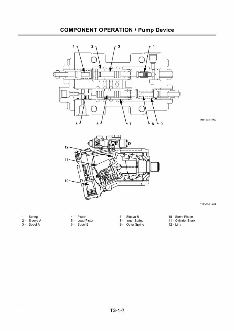
REGULATOR
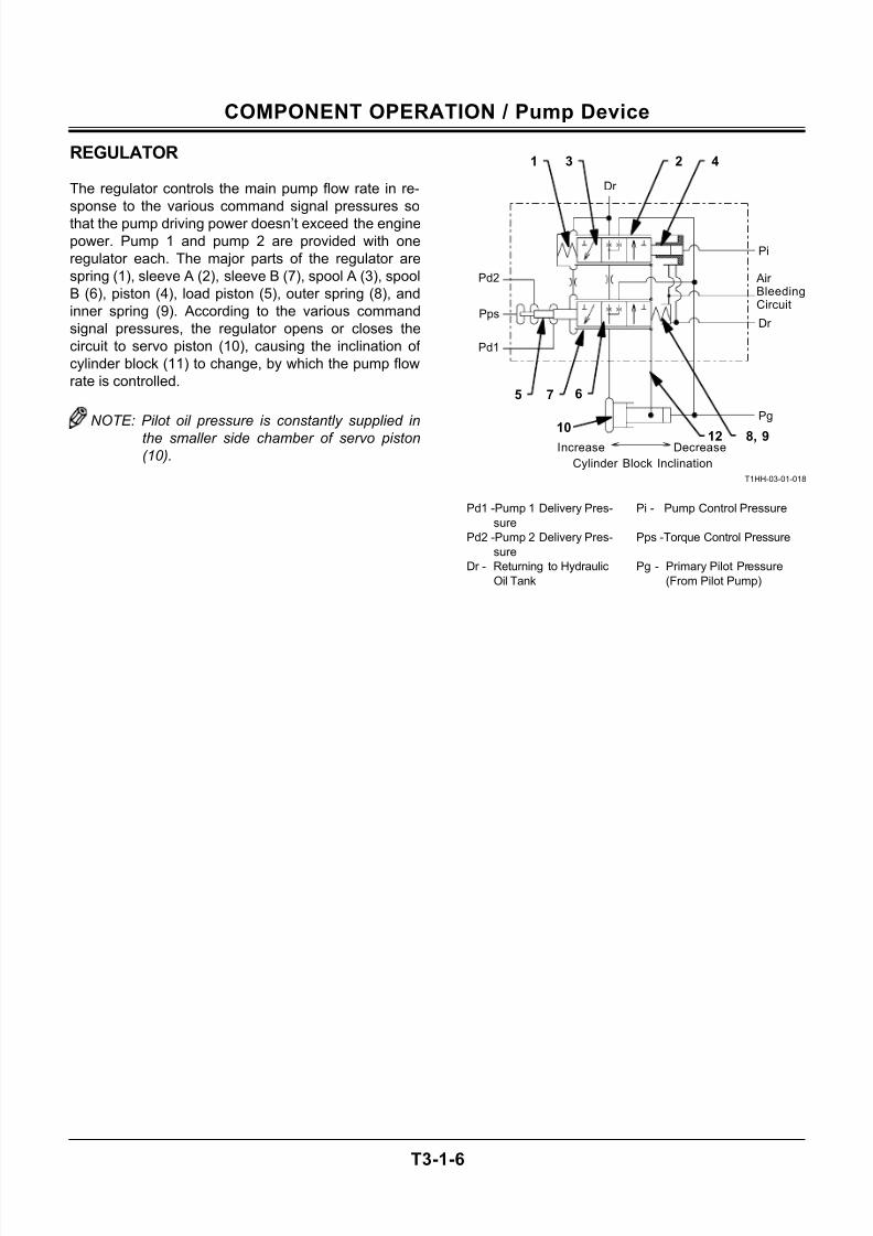
The regulator controls the main pump flow rate in re-
sponse to the various command signal pressures so
that the pump driving power doesn’t exceed the engine
power. Pump 1 and pump 2 are provided with one
regulator each. The major parts of the regulator are
spring (1), sleeve A (2), sleeve B (7), spool A (3), spool
B (6), piston (4), load piston (5), outer spring (8), and
inner spring (9). According to the various command
signal pressures, the regulator opens or closes the
circuit to servo piston (10), causing the inclination of
cylinder block (11) to change, by which the pump flow
rate is controlled.
NOTE: Pilot oil pressure is constantly supplied in
the smaller side chamber of servo piston(10).
T1HH-03-01-018
Pd1 -Pump 1 Delivery Pres-
sure
Pi - Pump Control Pressure
Pd2 -Pump 2 Delivery Pres-
sure
Pps -Torque Control Pressure
Dr - Returning to Hydraulic
Oil Tank
Pg - Primary Pilot Pressure
(From Pilot Pump)
421 3
7
8, 912
65
Increase Decrease
Pd1
Pps
Dr
Pg
Dr
Air BleedingCircuit
Pi
Pd2
10
Cylinder Block Inclination
7/24/2019 t03 hitachi
http://slidepdf.com/reader/full/t03-hitachi 9/104
COMPONENT OPERATION / Pump Device
T3-1-7
T1HH-03-01-002
T173-03-01-004
1 - Spring 4 - Piston 7 - Sleeve B 10 - Servo Piston
2 - Sleeve A 5 - Load Piston 8 - Inner Spring 11 - Cylinder Block
3 - Spool A 6 - Spool B 9 - Outer Spring 12 - Link
1 2 3 4
5 6 7 8 9
12
11
10
7/24/2019 t03 hitachi
http://slidepdf.com/reader/full/t03-hitachi 10/104
COMPONENT OPERATION / Pump Device
T3-1-8
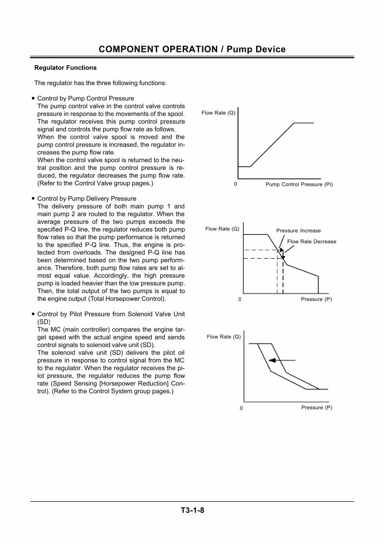
Regulator Functions
The regulator has the three following functions:
• Control by Pump Control Pressure
The pump control valve in the control valve controls
pressure in response to the movements of the spool.
The regulator receives this pump control pressure
signal and controls the pump flow rate as follows.
When the control valve spool is moved and the
pump control pressure is increased, the regulator in-
creases the pump flow rate.
When the control valve spool is returned to the neu-
tral position and the pump control pressure is re-
duced, the regulator decreases the pump flow rate.
(Refer to the Control Valve group pages.)
• Control by Pump Delivery Pressure
The delivery pressure of both main pump 1 and
main pump 2 are routed to the regulator. When the
average pressure of the two pumps exceeds the
specified P-Q line, the regulator reduces both pump
flow rates so that the pump performance is returned
to the specified P-Q line. Thus, the engine is pro-
tected from overloads. The designed P-Q line has
been determined based on the two pump perform-
ance. Therefore, both pump flow rates are set to al-
most equal value. Accordingly, the high pressure
pump is loaded heavier than the low pressure pump.Then, the total output of the two pumps is equal to
the engine output (Total Horsepower Control).
• Control by Pilot Pressure from Solenoid Valve Unit
(SD)
The MC (main controller) compares the engine tar-
get speed with the actual engine speed and sends
control signals to solenoid valve unit (SD).
The solenoid valve unit (SD) delivers the pilot oil
pressure in response to control signal from the MC
to the regulator. When the regulator receives the pi-
lot pressure, the regulator reduces the pump flow
rate (Speed Sensing [Horsepower Reduction] Con-trol). (Refer to the Control System group pages.)
Flow Rate (Q)
Pump Control Pressure (Pi)0
Flow Rate Decrease
Pressure Increase
Pressure (P)0
Flow Rate (Q)
Pressure (P)0
Flow Rate (Q)
7/24/2019 t03 hitachi
http://slidepdf.com/reader/full/t03-hitachi 11/104
COMPONENT OPERATION / Pump Device
T3-1-9
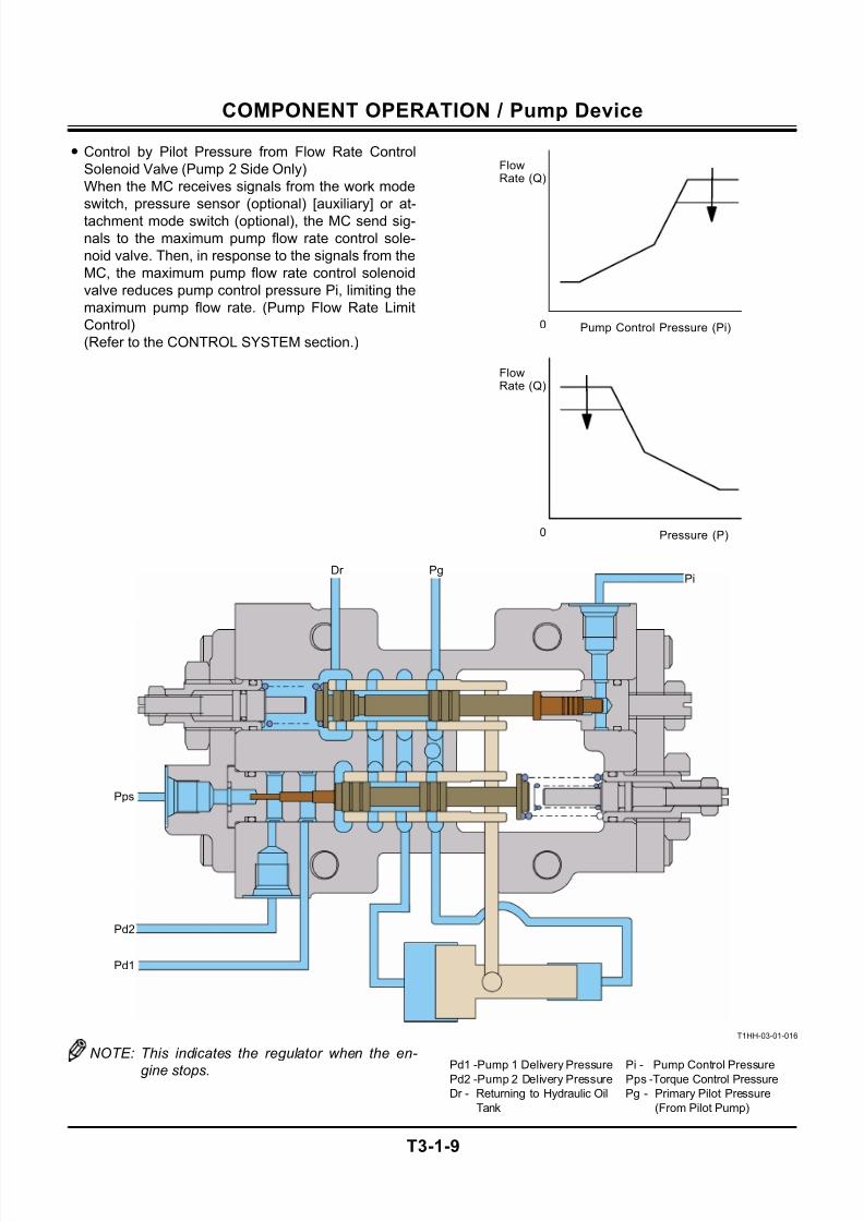
• Control by Pilot Pressure from Flow Rate Control
Solenoid Valve (Pump 2 Side Only)
When the MC receives signals from the work mode
switch, pressure sensor (optional) [auxiliary] or at-
tachment mode switch (optional), the MC send sig-
nals to the maximum pump flow rate control sole-
noid valve. Then, in response to the signals from the
MC, the maximum pump flow rate control solenoid
valve reduces pump control pressure Pi, limiting the
maximum pump flow rate. (Pump Flow Rate Limit
Control)
(Refer to the CONTROL SYSTEM section.)
T1HH-03-01-016
NOTE: This indicates the regulator when the en-
gine stops. Pd1 -Pump 1 Delivery Pressure Pi - Pump Control PressurePd2 -Pump 2 Delivery Pressure Pps -Torque Control Pressure
Dr - Returning to Hydraulic Oil
Tank
Pg - Primary Pilot Pressure
(From Pilot Pump)
FlowRate (Q)
Pressure (P)0
FlowRate (Q)
Pump Control Pressure (Pi)0
Pd1
Pd2
Pps
PgPi
Dr
7/24/2019 t03 hitachi
http://slidepdf.com/reader/full/t03-hitachi 12/104
COMPONENT OPERATION / Pump Device
T3-1-10
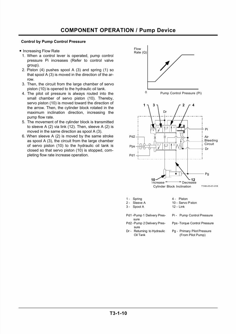
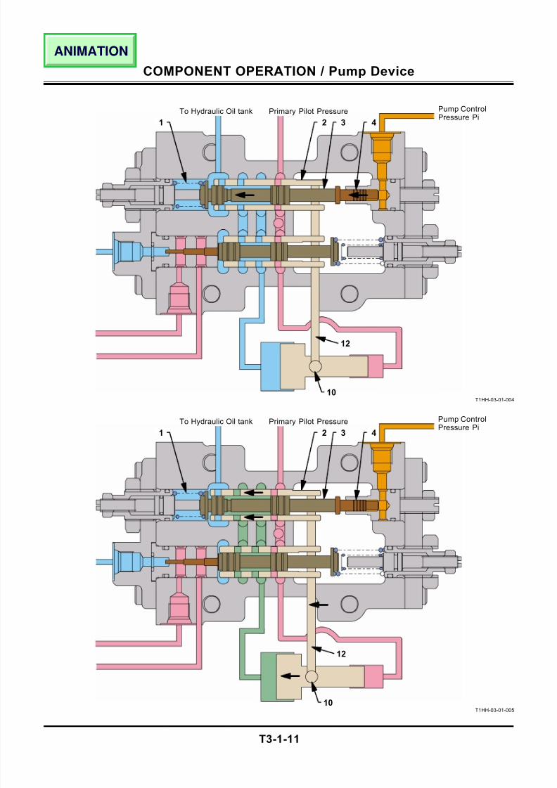
Control by Pump Control Pressure
• Increasing Flow Rate
1. When a control lever is operated, pump control
pressure Pi increases (Refer to control valve
group).
2. Piston (4) pushes spool A (3) and spring (1) so
that spool A (3) is moved in the direction of the ar-
row.
3. Then, the circuit from the large chamber of servo
piston (10) is opened to the hydraulic oil tank.
4. The pilot oil pressure is always routed into the
small chamber of servo piston (10). Thereby,
servo piston (10) is moved toward the direction of
the arrow. Then, the cylinder block rotated in the
maximum inclination direction, increasing the
pump flow rate.5. The movement of the cylinder block is transmitted
to sleeve A (2) via link (12). Then, sleeve A (2) is
moved in the same direction as spool A (3).
6. When sleeve A (2) is moved by the same stroke
as spool A (3), the circuit from the large chamber
of servo piston (10) to the hydraulic oil tank is
closed so that servo piston (10) is stopped, com-
pleting flow rate increase operation.
T1HH-03-01-018
1 - Spring 4 - Piston
2 - Sleeve A 10 - Servo Piston
3 - Spool A 12 - Link
Pd1 -Pump 1 Delivery Pres-
sure
Pi - Pump Control Pressure
Pd2 - Pump 2 Delivery Pres-
sure
Pps -Torque Control Pressure
Dr - Returning to Hydraulic
Oil Tank
Pg - Primary Pilot Pressure
(From Pilot Pump)
421 3
10
FlowRate (Q)
Pump Control Pressure (Pi)0
12Increase Decrease
Cylinder Block Inclination
Pd1
Pps
Dr
Pg
Dr
Air BleedingCircuit
Pi
Pd2
7/24/2019 t03 hitachi
http://slidepdf.com/reader/full/t03-hitachi 13/104
COMPONENT OPERATION / Pump Device
T3-1-11
T1HH-03-01-004
T1HH-03-01-005
1
Pump ControlPressure Pi
Primary Pilot PressureTo Hydraulic Oil tank
2 3 4
12
10
1
Pump ControlPressure Pi
Primary Pilot PressureTo Hydraulic Oil tank
2 3 4
12
10
ANIMATION
7/24/2019 t03 hitachi
http://slidepdf.com/reader/full/t03-hitachi 14/104
COMPONENT OPERATION / Pump Device
T3-1-12
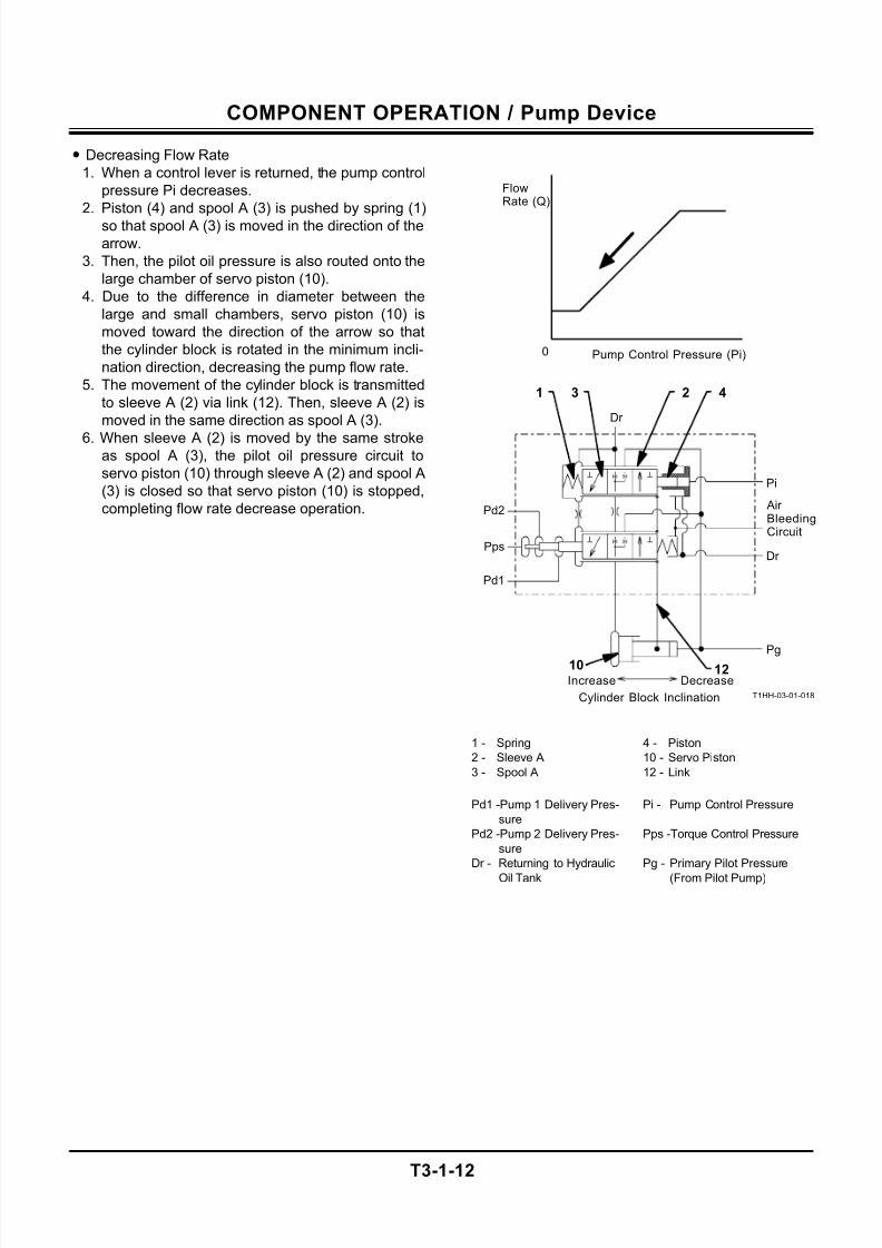
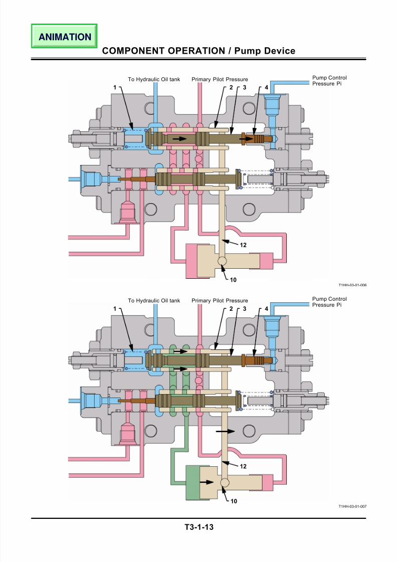
• Decreasing Flow Rate
1. When a control lever is returned, the pump control
pressure Pi decreases.
2. Piston (4) and spool A (3) is pushed by spring (1)
so that spool A (3) is moved in the direction of the
arrow.
3. Then, the pilot oil pressure is also routed onto the
large chamber of servo piston (10).
4. Due to the difference in diameter between the
large and small chambers, servo piston (10) is
moved toward the direction of the arrow so that
the cylinder block is rotated in the minimum incli-
nation direction, decreasing the pump flow rate.
5. The movement of the cylinder block is transmitted
to sleeve A (2) via link (12). Then, sleeve A (2) is
moved in the same direction as spool A (3).
6. When sleeve A (2) is moved by the same strokeas spool A (3), the pilot oil pressure circuit to
servo piston (10) through sleeve A (2) and spool A
(3) is closed so that servo piston (10) is stopped,
completing flow rate decrease operation.
T1HH-03-01-018
1 - Spring 4 - Piston
2 - Sleeve A 10 - Servo Piston
3 - Spool A 12 - Link
Pd1 -Pump 1 Delivery Pres-
sure
Pi - Pump Control Pressure
Pd2 -Pump 2 Delivery Pres-
sure
Pps -Torque Control Pressure
Dr - Returning to Hydraulic
Oil Tank
Pg - Primary Pilot Pressure
(From Pilot Pump)
421 3
FlowRate (Q)
Pump Control Pressure (Pi)0
Increase Decrease
Cylinder Block Inclination
Pd1
Pps
Dr
Pg
Dr
Air BleedingCircuit
Pi
Pd2
1210
7/24/2019 t03 hitachi
http://slidepdf.com/reader/full/t03-hitachi 15/104
COMPONENT OPERATION / Pump Device
T3-1-13
T1HH-03-01-006
T1HH-03-01-007
1
Pump ControlPressure Pi
Primary Pilot PressureTo Hydraulic Oil tank
2 3 4
12
10
1
Pump ControlPressure Pi
Primary Pilot PressureTo Hydraulic Oil tank
2 3 4
12
10
ANIMATION
7/24/2019 t03 hitachi
http://slidepdf.com/reader/full/t03-hitachi 16/104
COMPONENT OPERATION / Pump Device
T3-1-14
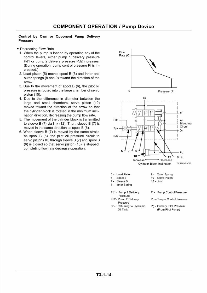
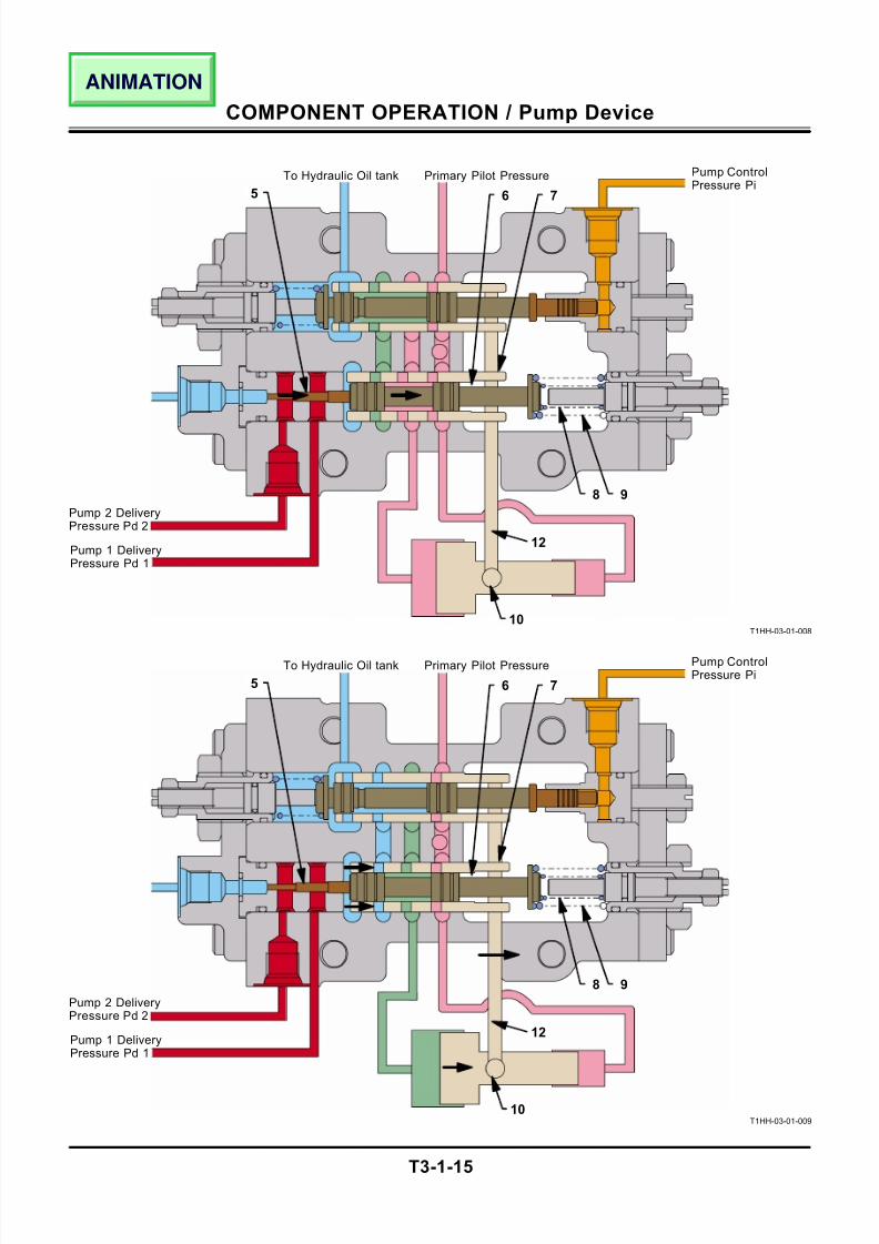
Control by Own or Opponent Pump Delivery
Pressure
• Decreasing Flow Rate
1. When the pump is loaded by operating any of the
control levers, either pump 1 delivery pressure
Pd1 or pump 2 delivery pressure Pd2 increases.
(During operation, pump control pressure Pi is in-
creased.)
2. Load piston (5) moves spool B (6) and inner and
outer springs (8 and 9) toward the direction of the
arrow.
3. Due to the movement of spool B (6), the pilot oil
pressure is routed into the large chamber of servo
piston (10).
4. Due to the difference in diameter between the
large and small chambers, servo piston (10)moved toward the direction of the arrow so that
the cylinder block is rotated in the minimum incli-
nation direction, decreasing the pump flow rate.
5. The movement of the cylinder block is transmitted
to sleeve B (7) via link (12). Then, sleeve B (7) is
moved in the same direction as spool B (6).
6. When sleeve B (7) is moved by the same stroke
as spool B (6), the pilot oil pressure circuit to
servo piston (10) through sleeve B (7) and spool B
(6) is closed so that servo piston (10) is stopped,
completing flow rate decrease operation.
T1HH-03-01-018
5 - Load Piston 9 - Outer Spring
6 - Spool B 10 - Servo Piston
7 - Sleeve B 12 - Link
8 - Inner Spring
Pd1 - Pump 1 Delivery
Pressure
Pi - Pump Control Pressure
Pd2 - Pump 2 Delivery
Pressure
Pps -Torque Control Pressure
Dr - Returning to HydraulicOil Tank
Pg - Primary Pilot Pressure(From Pilot Pump)
7
8, 912
65
Increase Decrease
Cylinder Block Inclination
Pd2
Pps
Dr
Pg
Dr
Air BleedingCircuit
Pi
Pd1
FlowRate (Q)
Pressure (P)0
10
7/24/2019 t03 hitachi
http://slidepdf.com/reader/full/t03-hitachi 17/104
COMPONENT OPERATION / Pump Device
T3-1-15
T1HH-03-01-008
T1HH-03-01-009
5
Pump ControlPressure Pi
Primary Pilot PressureTo Hydraulic Oil tank
6 7
12
10
5
Pump ControlPressure Pi
Primary Pilot PressureTo Hydraulic Oil tank
12
10
8 9
6 7
8 9
Pump 1 DeliveryPressure Pd 1
Pump 2 DeliveryPressure Pd 2
Pump 1 DeliveryPressure Pd 1
Pump 2 DeliveryPressure Pd 2
ANIMATION
7/24/2019 t03 hitachi
http://slidepdf.com/reader/full/t03-hitachi 18/104
COMPONENT OPERATION / Pump Device
T3-1-16
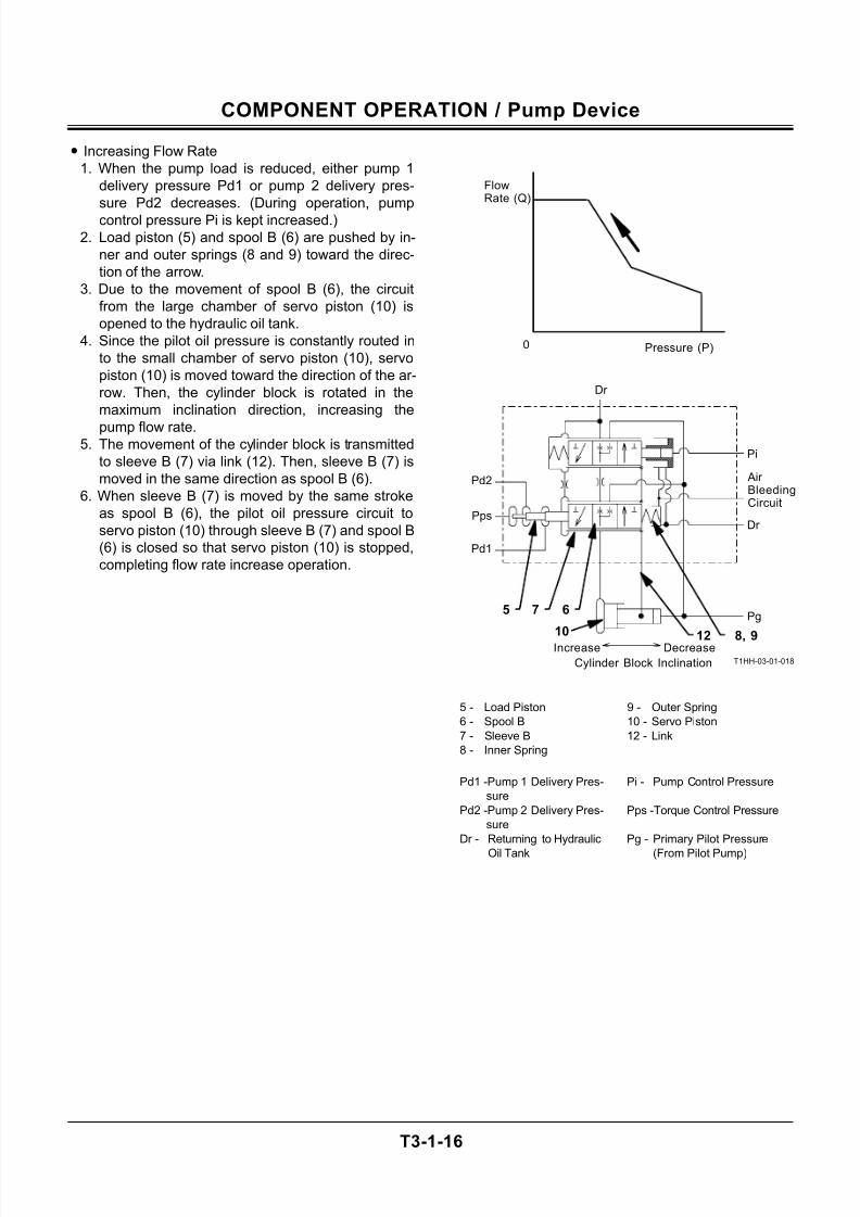
• Increasing Flow Rate
1. When the pump load is reduced, either pump 1
delivery pressure Pd1 or pump 2 delivery pres-
sure Pd2 decreases. (During operation, pump
control pressure Pi is kept increased.)
2. Load piston (5) and spool B (6) are pushed by in-
ner and outer springs (8 and 9) toward the direc-
tion of the arrow.
3. Due to the movement of spool B (6), the circuit
from the large chamber of servo piston (10) is
opened to the hydraulic oil tank.
4. Since the pilot oil pressure is constantly routed in
to the small chamber of servo piston (10), servo
piston (10) is moved toward the direction of the ar-
row. Then, the cylinder block is rotated in the
maximum inclination direction, increasing the
pump flow rate.5. The movement of the cylinder block is transmitted
to sleeve B (7) via link (12). Then, sleeve B (7) is
moved in the same direction as spool B (6).
6. When sleeve B (7) is moved by the same stroke
as spool B (6), the pilot oil pressure circuit to
servo piston (10) through sleeve B (7) and spool B
(6) is closed so that servo piston (10) is stopped,
completing flow rate increase operation.
T1HH-03-01-018
5 - Load Piston 9 - Outer Spring
6 - Spool B 10 - Servo Piston
7 - Sleeve B 12 - Link
8 - Inner Spring
Pd1 -Pump 1 Delivery Pres-
sure
Pi - Pump Control Pressure
Pd2 -Pump 2 Delivery Pres-
sure
Pps -Torque Control Pressure
Dr - Returning to Hydraulic
Oil Tank
Pg - Primary Pilot Pressure
(From Pilot Pump)
7
FlowRate (Q)
Pressure (P)0
65
Increase Decrease
Cylinder Block Inclination
Pd1
Pps
Dr
Pg
Dr
Air BleedingCircuit
Pi
Pd2
108, 912
7/24/2019 t03 hitachi
http://slidepdf.com/reader/full/t03-hitachi 19/104
COMPONENT OPERATION / Pump Device
T3-1-17
T1HH-03-01-010
T1HH-03-01-011
5
Pump ControlPressure Pi
Primary Pilot PressureTo Hydraulic Oil tank
6 7
12
10
5
Pump ControlPressure Pi
Primary Pilot PressureTo Hydraulic Oil tank
12
10
8 9
6 7
8 9
Pump 1 DeliveryPressure Pd 1
Pump 2 DeliveryPressure Pd 2
Pump 1 DeliveryPressure Pd 1
Pump 2 DeliveryPressure Pd 2
ANIMATION
7/24/2019 t03 hitachi
http://slidepdf.com/reader/full/t03-hitachi 20/104
COMPONENT OPERATION / Pump Device
T3-1-18
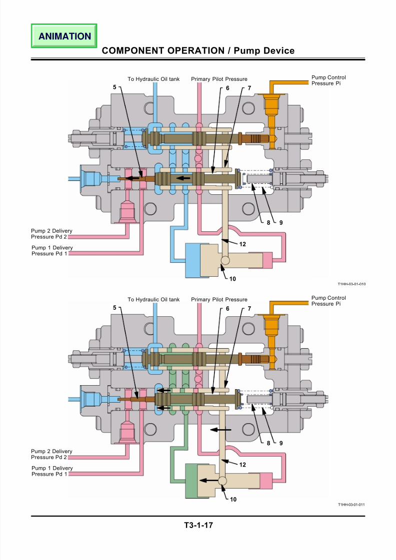
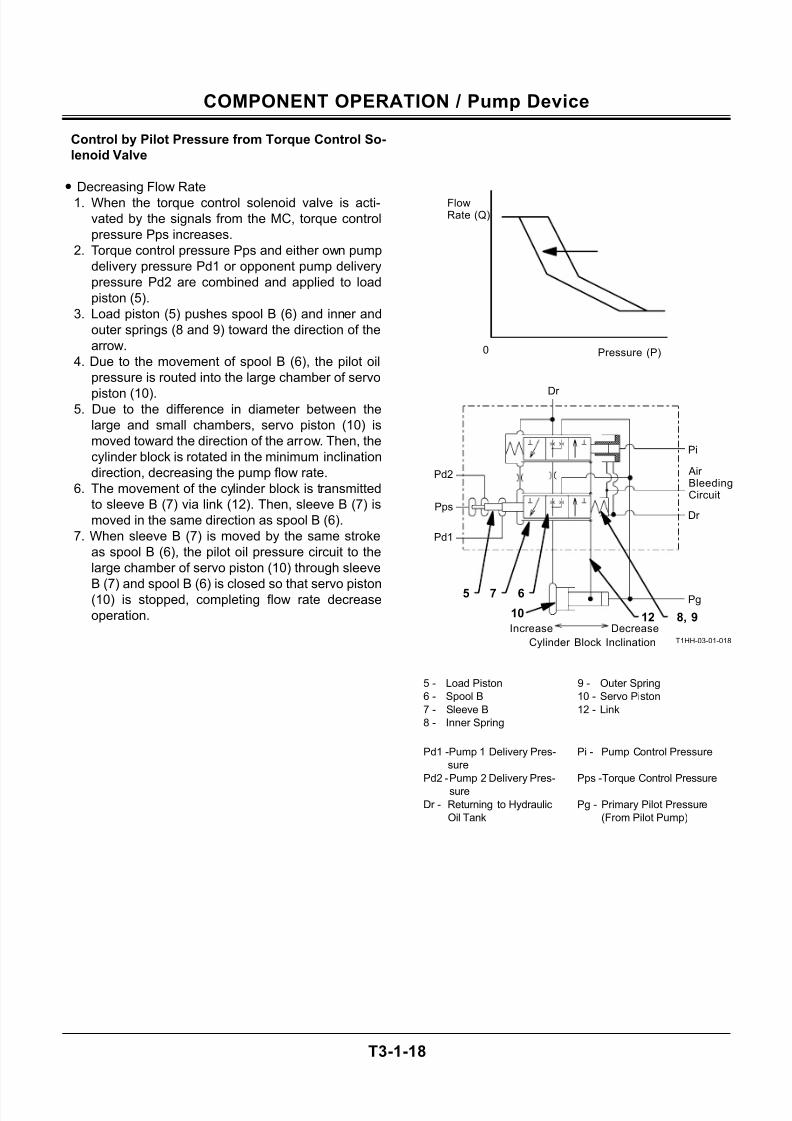
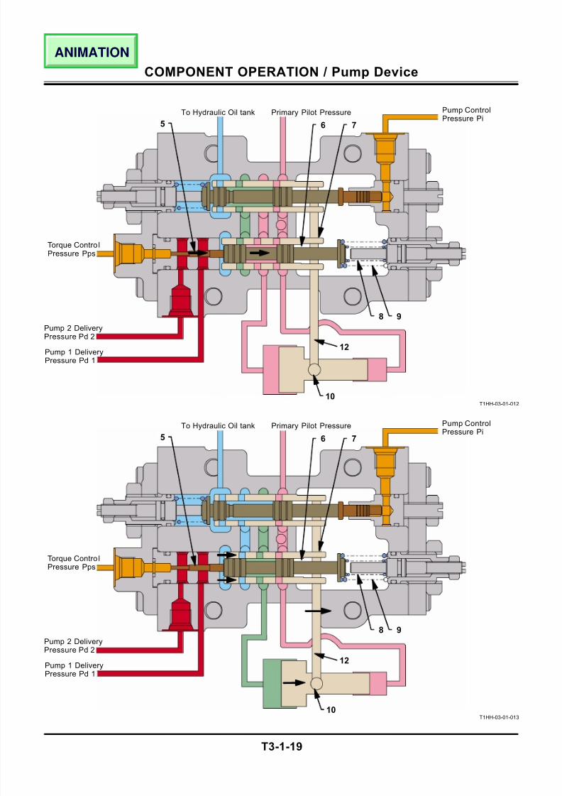
Control by Pilot Pressure from Torque Control So-
lenoid Valve
• Decreasing Flow Rate
1. When the torque control solenoid valve is acti-
vated by the signals from the MC, torque control
pressure Pps increases.
2. Torque control pressure Pps and either own pump
delivery pressure Pd1 or opponent pump delivery
pressure Pd2 are combined and applied to load
piston (5).
3. Load piston (5) pushes spool B (6) and inner and
outer springs (8 and 9) toward the direction of the
arrow.
4. Due to the movement of spool B (6), the pilot oil
pressure is routed into the large chamber of servo
piston (10).5. Due to the difference in diameter between the
large and small chambers, servo piston (10) is
moved toward the direction of the arrow. Then, the
cylinder block is rotated in the minimum inclination
direction, decreasing the pump flow rate.
6. The movement of the cylinder block is transmitted
to sleeve B (7) via link (12). Then, sleeve B (7) is
moved in the same direction as spool B (6).
7. When sleeve B (7) is moved by the same stroke
as spool B (6), the pilot oil pressure circuit to the
large chamber of servo piston (10) through sleeve
B (7) and spool B (6) is closed so that servo piston(10) is stopped, completing flow rate decrease
operation.
T1HH-03-01-018
5 - Load Piston 9 - Outer Spring
6 - Spool B 10 - Servo Piston
7 - Sleeve B 12 - Link
8 - Inner Spring
Pd1 -Pump 1 Delivery Pres-
sure
Pi - Pump Control Pressure
Pd2 - Pump 2 Delivery Pres-
sure
Pps -Torque Control Pressure
Dr - Returning to Hydraulic
Oil Tank
Pg - Primary Pilot Pressure
(From Pilot Pump)
7
FlowRate (Q)
Pressure (P)0
65
Increase Decrease
Cylinder Block Inclination
Pd1
Pps
Dr
Pg
Dr
Air BleedingCircuit
Pi
Pd2
10 8, 912
7/24/2019 t03 hitachi
http://slidepdf.com/reader/full/t03-hitachi 21/104
COMPONENT OPERATION / Pump Device
T3-1-19
T1HH-03-01-012
T1HH-03-01-013
5
Pump ControlPressure Pi
Primary Pilot PressureTo Hydraulic Oil tank
6 7
12
10
5
Pump ControlPressure Pi
Primary Pilot PressureTo Hydraulic Oil tank
12
10
8 9
6 7
8 9
Pump 1 DeliveryPressure Pd 1
Pump 2 DeliveryPressure Pd 2
Pump 1 DeliveryPressure Pd 1
Pump 2 DeliveryPressure Pd 2
Torque Contro lPressure Pps
Torque Contro lPressure Pps
ANIMATION
7/24/2019 t03 hitachi
http://slidepdf.com/reader/full/t03-hitachi 22/104
COMPONENT OPERATION / Pump Device
T3-1-20
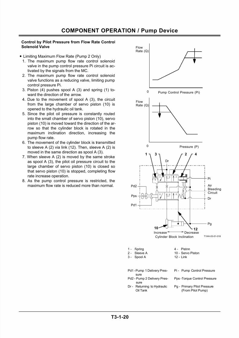
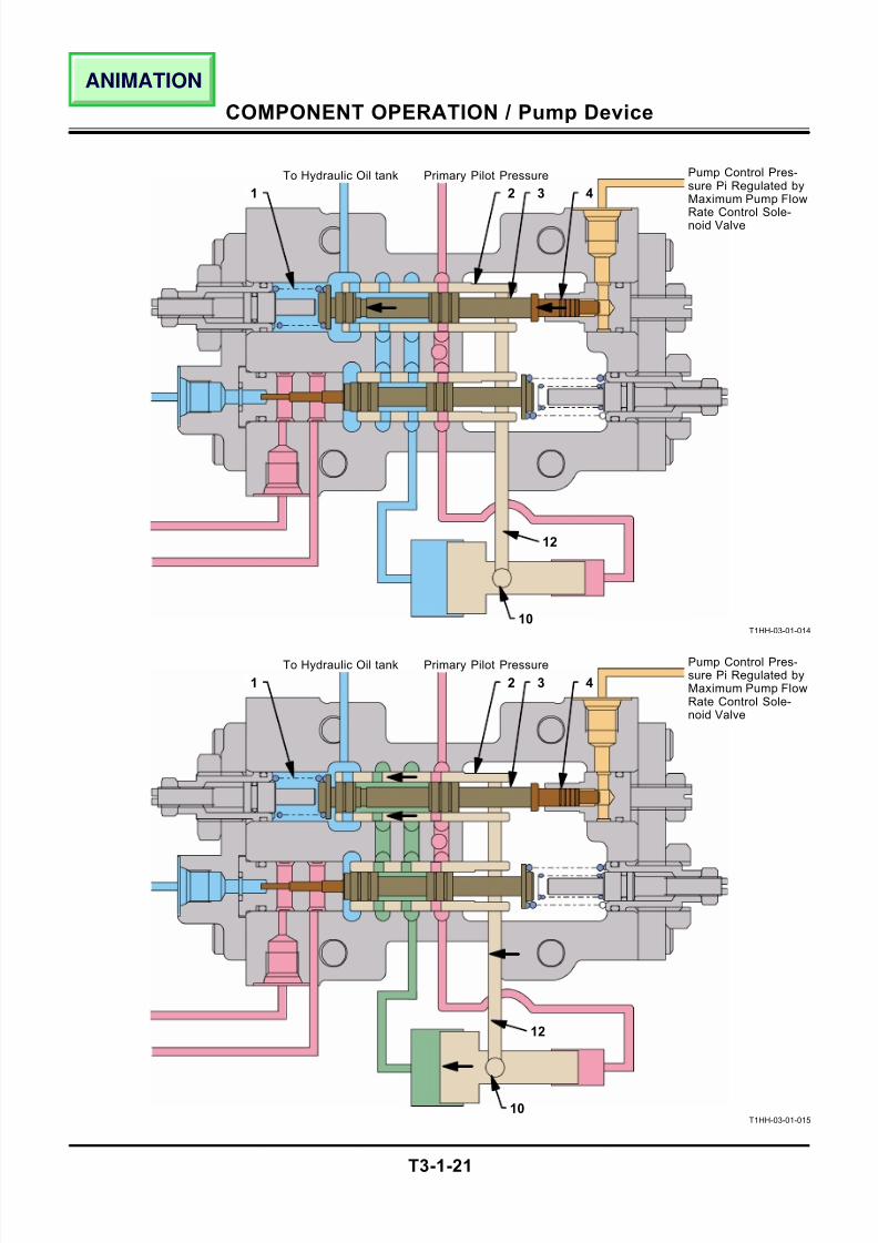
Control by Pilot Pressure from Flow Rate Control
Solenoid Valve
• Limiting Maximum Flow Rate (Pump 2 Only)
1. The maximum pump flow rate control solenoid
valve in the pump control pressure Pi circuit is ac-
tivated by the signals from the MC.
2. The maximum pump flow rate control solenoid
valve functions as a reducing valve, limiting pump
control pressure Pi.
3. Piston (4) pushes spool A (3) and spring (1) to-
ward the direction of the arrow.
4. Due to the movement of spool A (3), the circuit
from the large chamber of servo piston (10) is
opened to the hydraulic oil tank.
5. Since the pilot oil pressure is constantly routed
into the small chamber of servo piston (10), servopiston (10) is moved toward the direction of the ar-
row so that the cylinder block is rotated in the
maximum inclination direction, increasing the
pump flow rate.
6. The movement of the cylinder block is transmitted
to sleeve A (2) via link (12). Then, sleeve A (2) is
moved in the same direction as spool A (3).
7. When sleeve A (2) is moved by the same stroke
as spool A (3), the pilot oil pressure circuit to the
large chamber of servo piston (10) is closed so
that servo piston (10) is stopped, completing flow
rate increase operation.8. As the pump control pressure is restricted, the
maximum flow rate is reduced more than normal.
T1HH-03-01-018
1 - Spring 4 - Piston
2 - Sleeve A 10 - Servo Piston
3 - Spool A 12 - Link
Pd1 - Pump 1 Delivery Pres-
sure
Pi - Pump Control Pressure
Pd2 - Pump 2 Delivery Pres-
sure
Pps -Torque Control Pressure
Dr - Returning to Hydraulic
Oil Tank
Pg - Primary Pilot Pressure
(From Pilot Pump)
421 3
Increase Decrease
Cylinder Block Inclination
Pd1
Pps
Dr
Pg
Dr
Air BleedingCircuit
Pi
Pd2
FlowRate (Q)
Pressure (P)0
10 12
FlowRate (Q)
Pump Control Pressure (Pi)0
7/24/2019 t03 hitachi
http://slidepdf.com/reader/full/t03-hitachi 23/104
COMPONENT OPERATION / Pump Device
T3-1-21
T1HH-03-01-014
T1HH-03-01-015
1
Primary Pilot PressureTo Hydraulic Oil tank
2 3 4
12
10
1
Primary Pilot PressureTo Hydraulic Oil tank
2 3 4
12
10
Pump Control Pres-sure Pi Regulated byMaximum Pump Flow
Rate Control Sole-noid Valve
Pump Control Pres-sure Pi Regulated byMaximum Pump FlowRate Control Sole-noid Valve
ANIMATION
7/24/2019 t03 hitachi
http://slidepdf.com/reader/full/t03-hitachi 24/104
COMPONENT OPERATION / Pump Device
T3-1-22
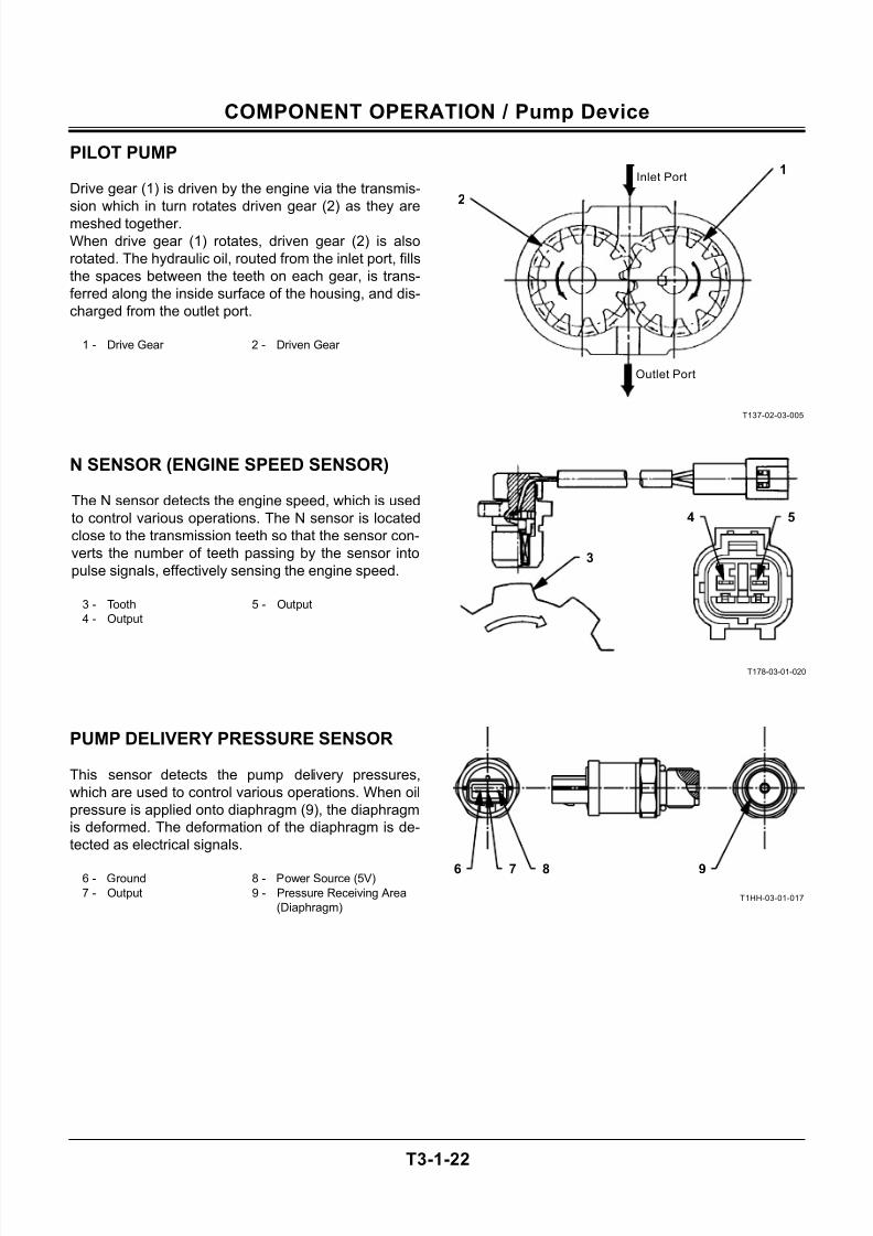
PILOT PUMP
Drive gear (1) is driven by the engine via the transmis-
sion which in turn rotates driven gear (2) as they are
meshed together.
When drive gear (1) rotates, driven gear (2) is also
rotated. The hydraulic oil, routed from the inlet port, fills
the spaces between the teeth on each gear, is trans-
ferred along the inside surface of the housing, and dis-
charged from the outlet port.
1 - Drive Gear 2 - Driven Gear
N SENSOR (ENGINE SPEED SENSOR)
The N sensor detects the engine speed, which is used
to control various operations. The N sensor is located
close to the transmission teeth so that the sensor con-
verts the number of teeth passing by the sensor into
pulse signals, effectively sensing the engine speed.
3 - Tooth 5 - Output
4 - Output
PUMP DELIVERY PRESSURE SENSOR
This sensor detects the pump delivery pressures,
which are used to control various operations. When oil
pressure is applied onto diaphragm (9), the diaphragm
is deformed. The deformation of the diaphragm is de-
tected as electrical signals.
6 - Ground 8 - Power Source (5V)
7 - Output 9 - Pressure Receiving Area
(Diaphragm)
T137-02-03-005
T178-03-01-020
T1HH-03-01-017
2
1Inlet Port
Outlet Port
4
3
5
6 7 8 9
7/24/2019 t03 hitachi
http://slidepdf.com/reader/full/t03-hitachi 25/104
COMPONENT OPERATION / Swing Device
T3-2-1
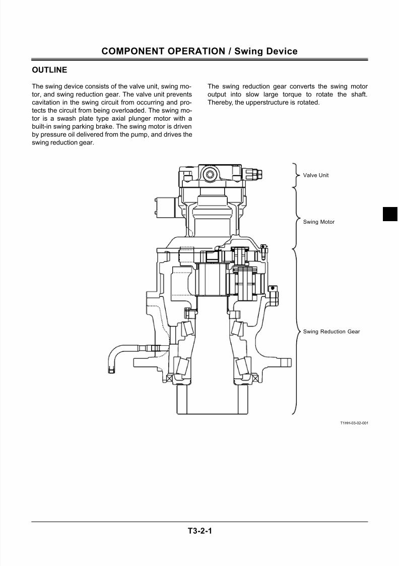
OUTLINE
The swing device consists of the valve unit, swing mo-
tor, and swing reduction gear. The valve unit prevents
cavitation in the swing circuit from occurring and pro-
tects the circuit from being overloaded. The swing mo-
tor is a swash plate type axial plunger motor with a
built-in swing parking brake. The swing motor is driven
by pressure oil delivered from the pump, and drives the
swing reduction gear.
The swing reduction gear converts the swing motor
output into slow large torque to rotate the shaft.
Thereby, the upperstructure is rotated.
T1HH-03-02-001
Swing Reduction Gear
Swing Motor
Valve Unit
7/24/2019 t03 hitachi
http://slidepdf.com/reader/full/t03-hitachi 26/104
COMPONENT OPERATION / Swing Device
T3-2-2
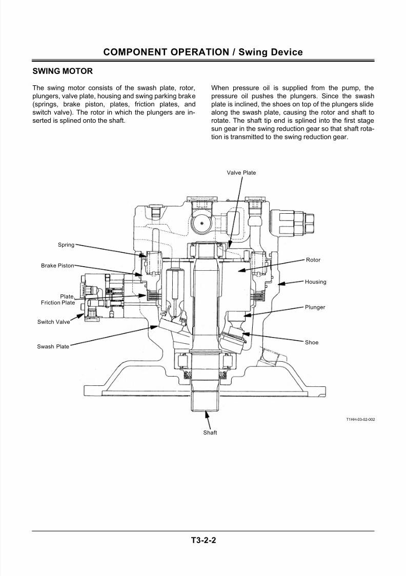
SWING MOTOR
The swing motor consists of the swash plate, rotor,
plungers, valve plate, housing and swing parking brake
(springs, brake piston, plates, friction plates, and
switch valve). The rotor in which the plungers are in-
serted is splined onto the shaft.
When pressure oil is supplied from the pump, the
pressure oil pushes the plungers. Since the swash
plate is inclined, the shoes on top of the plungers slide
along the swash plate, causing the rotor and shaft to
rotate. The shaft tip end is splined into the first stage
sun gear in the swing reduction gear so that shaft rota-
tion is transmitted to the swing reduction gear.
T1HH-03-02-002
Shoe
Shaft
Housing
Swash Plate
Plate,
Friction Plate
Spring
Valve Plate
Rotor
Plunger
Brake Piston
Switch Valve
7/24/2019 t03 hitachi
http://slidepdf.com/reader/full/t03-hitachi 27/104
COMPONENT OPERATION / Swing Device
T3-2-3
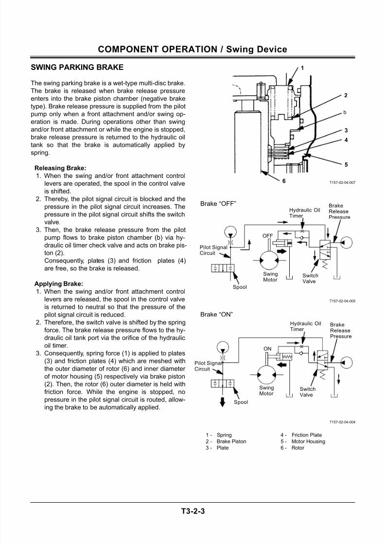
SWING PARKING BRAKE
The swing parking brake is a wet-type multi-disc brake.
The brake is released when brake release pressure
enters into the brake piston chamber (negative brake
type). Brake release pressure is supplied from the pilot
pump only when a front attachment and/or swing op-
eration is made. During operations other than swing
and/or front attachment or while the engine is stopped,
brake release pressure is returned to the hydraulic oil
tank so that the brake is automatically applied by
spring.
Releasing Brake:
1. When the swing and/or front attachment control
levers are operated, the spool in the control valve
is shifted.2. Thereby, the pilot signal circuit is blocked and the
pressure in the pilot signal circuit increases. The
pressure in the pilot signal circuit shifts the switch
valve.
3. Then, the brake release pressure from the pilot
pump flows to brake piston chamber (b) via hy-
draulic oil timer check valve and acts on brake pis-
ton (2).
Consequently, plates (3) and friction plates (4)
are free, so the brake is released.
Applying Brake:1. When the swing and/or front attachment control
levers are released, the spool in the control valve
is returned to neutral so that the pressure of the
pilot signal circuit is reduced.
2. Therefore, the switch valve is shifted by the spring
force. The brake release pressure flows to the hy-
draulic oil tank port via the orifice of the hydraulic
oil timer.
3. Consequently, spring force (1) is applied to plates
(3) and friction plates (4) which are meshed with
the outer diameter of rotor (6) and inner diameter
of motor housing (5) respectively via brake piston
(2). Then, the rotor (6) outer diameter is held withfriction force. While the engine is stopped, no
pressure in the pilot signal circuit is routed, allow-
ing the brake to be automatically applied.
T157-02-04-007
Brake “OFF”
T157-02-04-005
Brake “ON”
T157-02-04-004
1 - Spring 4 - Friction Plate
2 - Brake Piston 5 - Motor Housing
3 - Plate 6 - Rotor
1
2
3
4
5
6
b
SwitchValve
BrakeReleasePressure
Hydraulic OilTimer
OFF
SwingMotor
Spool
SwitchValve
BrakeReleasePressure
Hydraulic OilTimer
ON
SwingMotor
Spool
Pilot SignalCircuit
Pilot SignalCircuit
7/24/2019 t03 hitachi
http://slidepdf.com/reader/full/t03-hitachi 28/104
COMPONENT OPERATION / Swing Device
T3-2-4
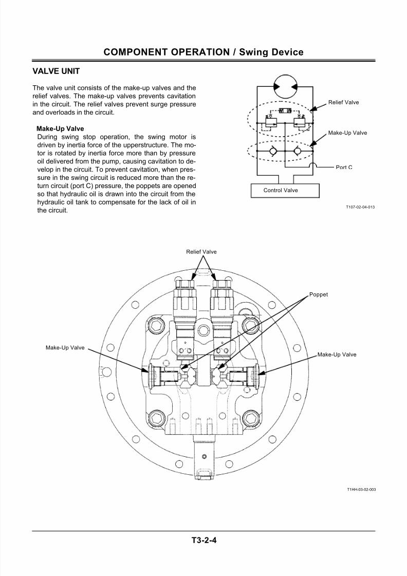
VALVE UNIT
The valve unit consists of the make-up valves and the
relief valves. The make-up valves prevents cavitation
in the circuit. The relief valves prevent surge pressure
and overloads in the circuit.
Make-Up Valve
During swing stop operation, the swing motor is
driven by inertia force of the upperstructure. The mo-
tor is rotated by inertia force more than by pressure
oil delivered from the pump, causing cavitation to de-
velop in the circuit. To prevent cavitation, when pres-
sure in the swing circuit is reduced more than the re-
turn circuit (port C) pressure, the poppets are opened
so that hydraulic oil is drawn into the circuit from the
hydraulic oil tank to compensate for the lack of oil inthe circuit.
T107-02-04-013
T1HH-03-02-003
Control Valve
Port C
Relief Valve
Make-Up Valve
Make-Up Valve
Relief Valve
Make-Up Valve
Poppet
7/24/2019 t03 hitachi
http://slidepdf.com/reader/full/t03-hitachi 29/104
COMPONENT OPERATION / Swing Device
T3-2-5
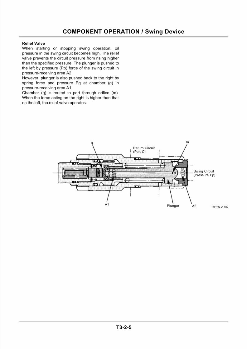
Relief Valve
When starting or stopping swing operation, oil
pressure in the swing circuit becomes high. The relief
valve prevents the circuit pressure from rising higher
than the specified pressure. The plunger is pushed to
the left by pressure (Pp) force of the swing circuit in
pressure-receiving area A2.
However, plunger is also pushed back to the right by
spring force and pressure Pg at chamber (g) in
pressure-receiving area A1.
Chamber (g) is routed to port through orifice (m).
When the force acting on the right is higher than that
on the left, the relief valve operates.
T107-02-04-020
g m
Swing Circuit(Pressure Pp)
A2 A1
Return Circuit(Port C)
Plunger
7/24/2019 t03 hitachi
http://slidepdf.com/reader/full/t03-hitachi 30/104
COMPONENT OPERATION / Swing Device
T3-2-6
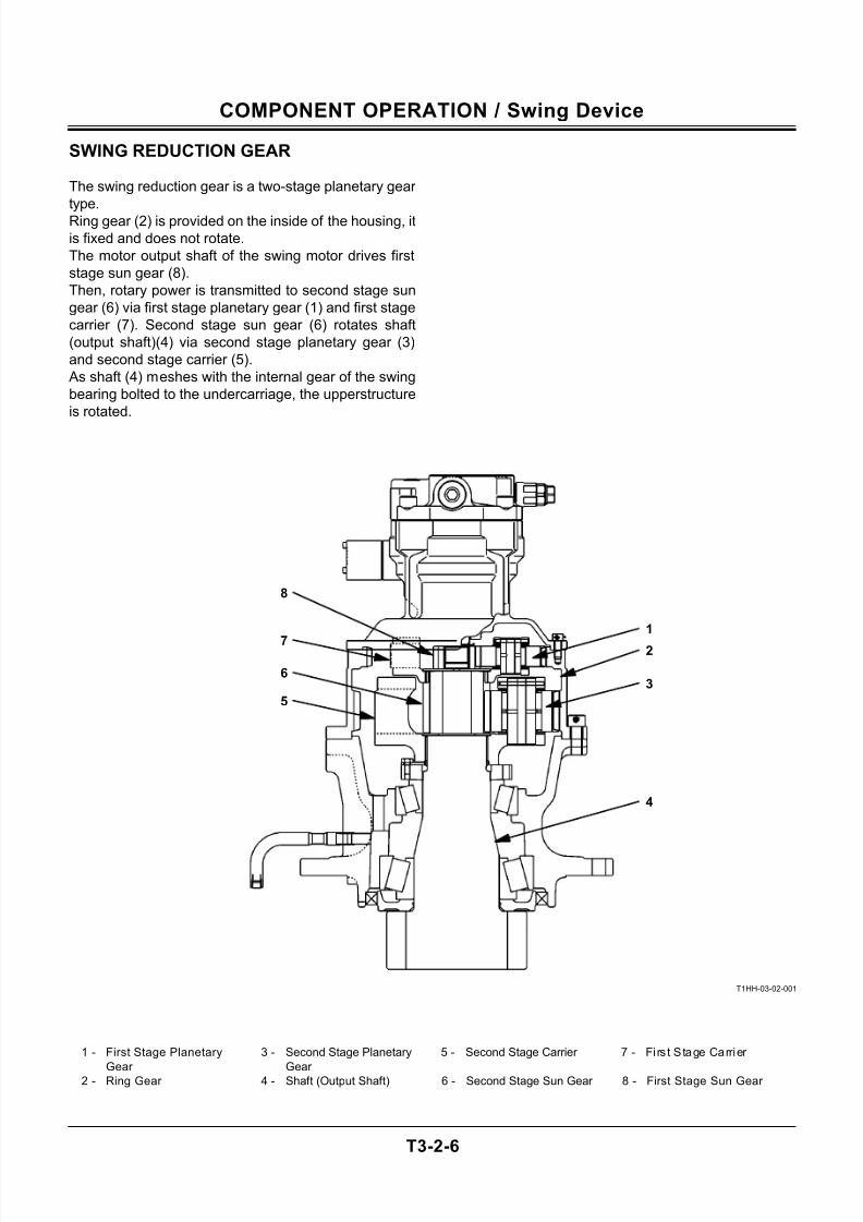
SWING REDUCTION GEAR
The swing reduction gear is a two-stage planetary gear
type.
Ring gear (2) is provided on the inside of the housing, it
is fixed and does not rotate.
The motor output shaft of the swing motor drives first
stage sun gear (8).
Then, rotary power is transmitted to second stage sun
gear (6) via first stage planetary gear (1) and first stage
carrier (7). Second stage sun gear (6) rotates shaft
(output shaft)(4) via second stage planetary gear (3)
and second stage carrier (5).
As shaft (4) meshes with the internal gear of the swing
bearing bolted to the undercarriage, the upperstructure
is rotated.
T1HH-03-02-001
1 - First Stage Planetary
Gear
3 - Second Stage Planetary
Gear
5 - Second Stage Carrier 7 - Fi rs t Stage Carrier
2 - Ring Gear 4 - Shaft (Output Shaft) 6 - Second Stage Sun Gear 8 - First Stage Sun Gear
1
2
3
4
7
8
6
5
7/24/2019 t03 hitachi
http://slidepdf.com/reader/full/t03-hitachi 31/104
COMPONENT OPERATION / Control Valve
T3-3-1
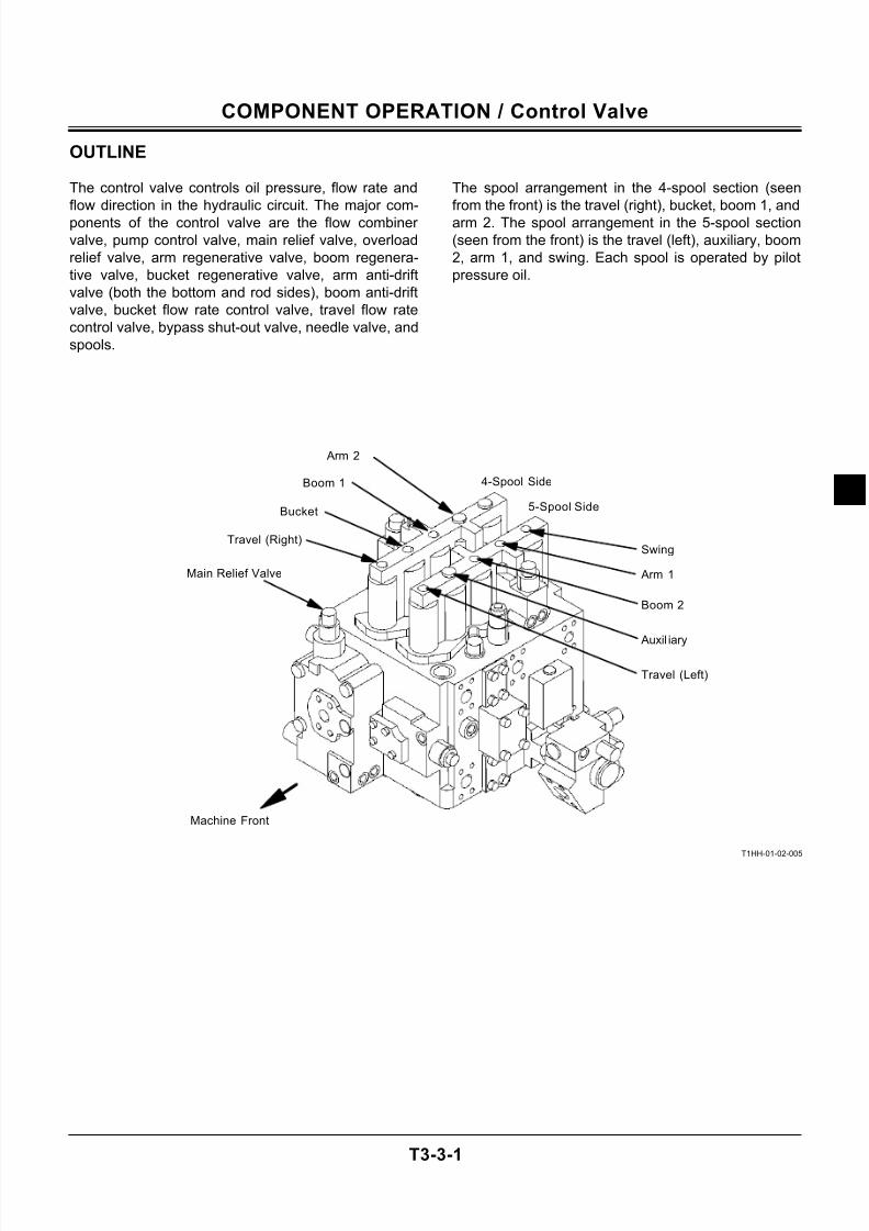
OUTLINE
The control valve controls oil pressure, flow rate and
flow direction in the hydraulic circuit. The major com-
ponents of the control valve are the flow combiner
valve, pump control valve, main relief valve, overload
relief valve, arm regenerative valve, boom regenera-
tive valve, bucket regenerative valve, arm anti-drift
valve (both the bottom and rod sides), boom anti-drift
valve, bucket flow rate control valve, travel flow rate
control valve, bypass shut-out valve, needle valve, and
spools.
The spool arrangement in the 4-spool section (seen
from the front) is the travel (right), bucket, boom 1, and
arm 2. The spool arrangement in the 5-spool section
(seen from the front) is the travel (left), auxiliary, boom
2, arm 1, and swing. Each spool is operated by pilot
pressure oil.
T1HH-01-02-005
Machine Front
Swing
Main Relief Valve
Travel (Right)
Bucket
Boom 1
Arm 2
Arm 1
Boom 2
Auxil iary
Travel (Left)
5-Spool Side
4-Spool Side
7/24/2019 t03 hitachi
http://slidepdf.com/reader/full/t03-hitachi 32/104
COMPONENT OPERATION / Control Valve
T3-3-2
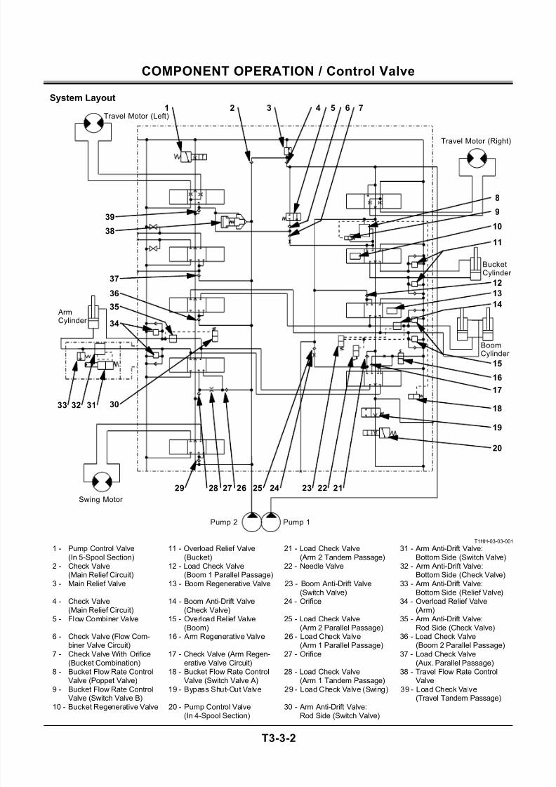
System Layout
T1HH-03-03-001
1 - Pump Control Valve(In 5-Spool Section) 11 - Overload Relief Valve(Bucket) 21 - Load Check Valve(Arm 2 Tandem Passage) 31 - Arm Anti-Drift Valve:Bottom Side (Switch Valve)2 - Check Valve
(Main Relief Circuit)12 - Load Check Valve
(Boom 1 Parallel Passage)22 - Needle Valve 32 - Arm Anti-Drift Valve:
Bottom Side (Check Valve)3 - Main Relief Valve 13 - Boom Regenerative Valve 23 - Boom Anti-Drift Valve
(Switch Valve)33 - Arm Anti-Drift Valve:
Bottom Side (Relief Valve)4 - Check Valve
(Main Relief Circuit)14 - Boom Anti-Drift Valve
(Check Valve)24 - Orifice 34 - Overload Relief Valve
(Arm)5 - Flow Combiner Valve 15 - Overload Relief Valve
(Boom)25 - Load Check Valve
(Arm 2 Parallel Passage)35 - Arm Anti-Drift Valve:
Rod Side (Check Valve)6 - Check Valve (Flow Com-
biner Valve Circuit)16 - Arm Regenerative Valve 26 - Load Check Valve
(Arm 1 Parallel Passage)36 - Load Check Valve
(Boom 2 Parallel Passage)7 - Check Valve With Orifice
(Bucket Combination)17 - Check Valve (Arm Regen-
erative Valve Circuit)27 - Orifice 37 - Load Check Valve
(Aux. Parallel Passage)8 - Bucket Flow Rate Control
Valve (Poppet Valve)18 - Bucket Flow Rate Control
Valve (Switch Valve A)28 - Load Check Valve
(Arm 1 Tandem Passage)38 - Travel Flow Rate Control
Valve
9 - Bucket Flow Rate ControlValve (Switch Valve B)
19 - Bypass Shut-Out Valve 29 - Load Check Valve (Swing) 39 - Load Check Valve(Travel Tandem Passage)
10 - Bucket Regenerative Valve 20 - Pump Control Valve(In 4-Spool Section)
30 - Arm Anti-Drift Valve:Rod Side (Switch Valve)
Travel Motor (Right)
Bucket
Cylinder
Pump 2 Pump 1
Swing Motor
ArmCylinder
1Travel Motor (Left)
2 3 4 5 6 7
8
12
9
11
20
19
18
23 22 2125
17
16
15
14
29 26
39
38
33 31
34
35
36
30
37
242728
32
13
10
BoomCylinder
7/24/2019 t03 hitachi
http://slidepdf.com/reader/full/t03-hitachi 33/104
COMPONENT OPERATION / Control Valve
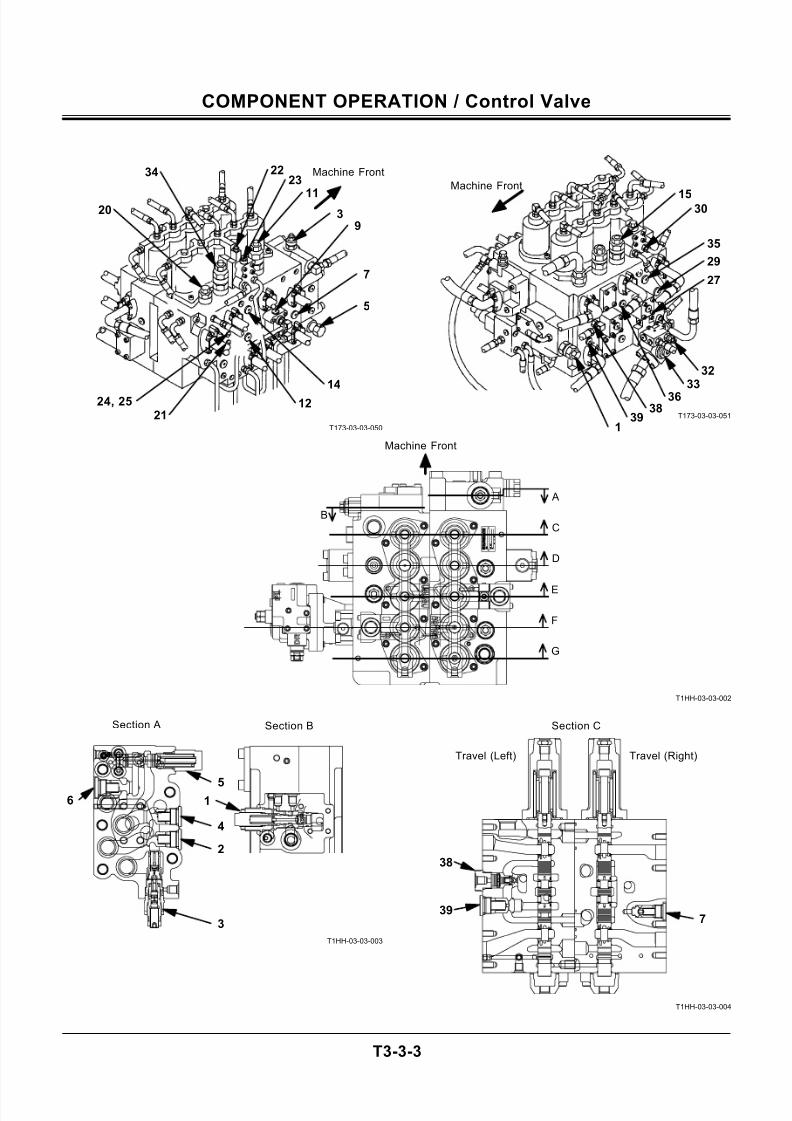
T3-3-3
T173-03-03-050
T173-03-03-051
T1HH-03-03-002
T1HH-03-03-003
T1HH-03-03-004
G
F
E
D
B
C
A
Section C
39
Travel (Right)Travel (Left)
38
7
Machine Front34
20
2223
113
9
7
5
14
1221
24, 25
1530
35
29
27
3233
3638
391
Machine Front
Machine Front
Section BSection A
65
4
2
3
1
7/24/2019 t03 hitachi
http://slidepdf.com/reader/full/t03-hitachi 34/104
COMPONENT OPERATION / Control Valve
T3-3-4
T1HH-03-03-001
1 - Pump Control Valve(In 5-Spool Section) 11 - Overload Relief Valve(Bucket) 21 - Load Check Valve(Arm 2 Tandem Passage) 31 - Arm Anti-Drift Valve:Bottom Side (Switch Valve)2 - Check Valve
(Main Relief Circuit)12 - Load Check Valve
(Boom 1 Parallel Passage)22 - Needle Valve 32 - Arm Anti-Drift Valve:
Bottom Side (Check Valve)3 - Main Relief Valve 13 - Boom Regenerative Valve 23 - Boom Anti-Drift Valve
(Switch Valve)33 - Arm Anti-Drift Valve:
Bottom Side (Relief Valve)4 - Check Valve
(Main Relief Circuit)14 - Boom Anti-Drift Valve
(Check Valve)24 - Orifice 34 - Overload Relief Valve
(Arm)5 - Flow Combiner Valve 15 - Overload Relief Valve
(Boom)25 - Load Check Valve
(Arm 2 Parallel Passage)35 - Arm Anti-Drift Valve:
Rod Side (Check Valve)6 - Check Valve (Flow Com-
biner Valve Circuit)16 - Arm Regenerative Valve 26 - Load Check Valve
(Arm 1 Parallel Passage)36 - Load Check Valve
(Boom 2 Parallel Passage)7 - Check Valve With Orifice
(Bucket Combination)17 - Check Valve (Arm Regen-
erative Valve Circuit)27 - Orifice 37 - Load Check Valve
(Aux. Parallel Passage)8 - Bucket Flow Rate Control
Valve (Poppet Valve)18 - Bucket Flow Rate Control
Valve (Switch Valve A)28 - Load Check Valve
(Arm 1 Tandem Passage)38 - Travel Flow Rate Control
Valve
9 - Bucket Flow Rate ControlValve (Switch Valve B)
19 - Bypass Shut-Out Valve 29 - Load Check Valve (Swing) 39 - Load Check Valve(Travel Tandem Passage)
10 - Bucket Regenerative Valve 20 - Pump Control Valve(In 4-Spool Section)
30 - Arm Anti-Drift Valve:Rod Side (Switch Valve)
Travel Motor (Right)
BoomCylinder
Bucket
Cylinder
Pump 2 Pump 1
Swing Motor
ArmCylinder
1 2 3 4 5 6 7
8
12
9
11
20
19
18
23 22 2125
17
16
15
14
29 26
39
38
33 31
34
35
36
30
37
242728
32
13
10
Travel Motor (Left)
7/24/2019 t03 hitachi
http://slidepdf.com/reader/full/t03-hitachi 35/104
COMPONENT OPERATION / Control Valve
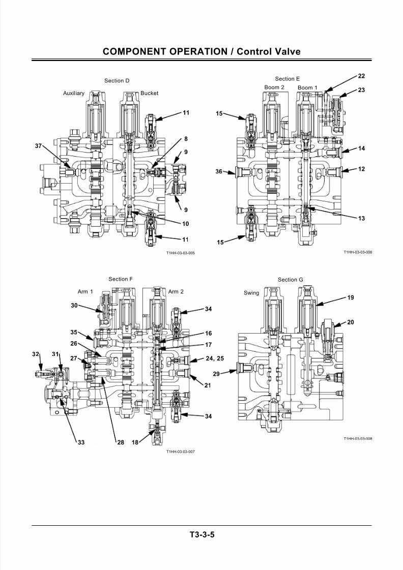
T3-3-5
T1HH-03-03-005
T1HH-03-03-007
T1HH-03-03-006
T1HH-03-03-008
Section F Section G
Arm 2 Arm 1
Section E
Boom 2 Boom 1 23
14
Section D
12
15
15
36
30
35
26
32 3124, 25
21
37
17
Bucket
18
Auxil iary
Swing
9
20
22
16
34
9
29
8
34
11
28
10
33
27
19
13
11
7/24/2019 t03 hitachi
http://slidepdf.com/reader/full/t03-hitachi 36/104
COMPONENT OPERATION / Control Valve
T3-3-6
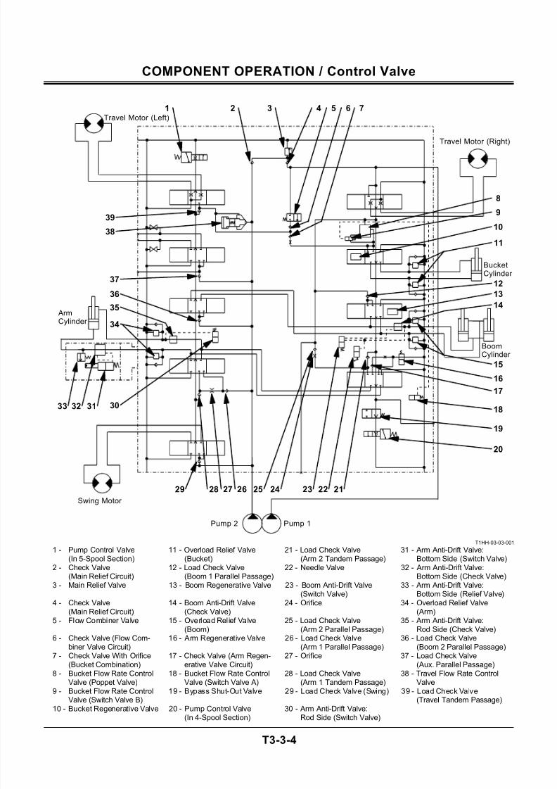
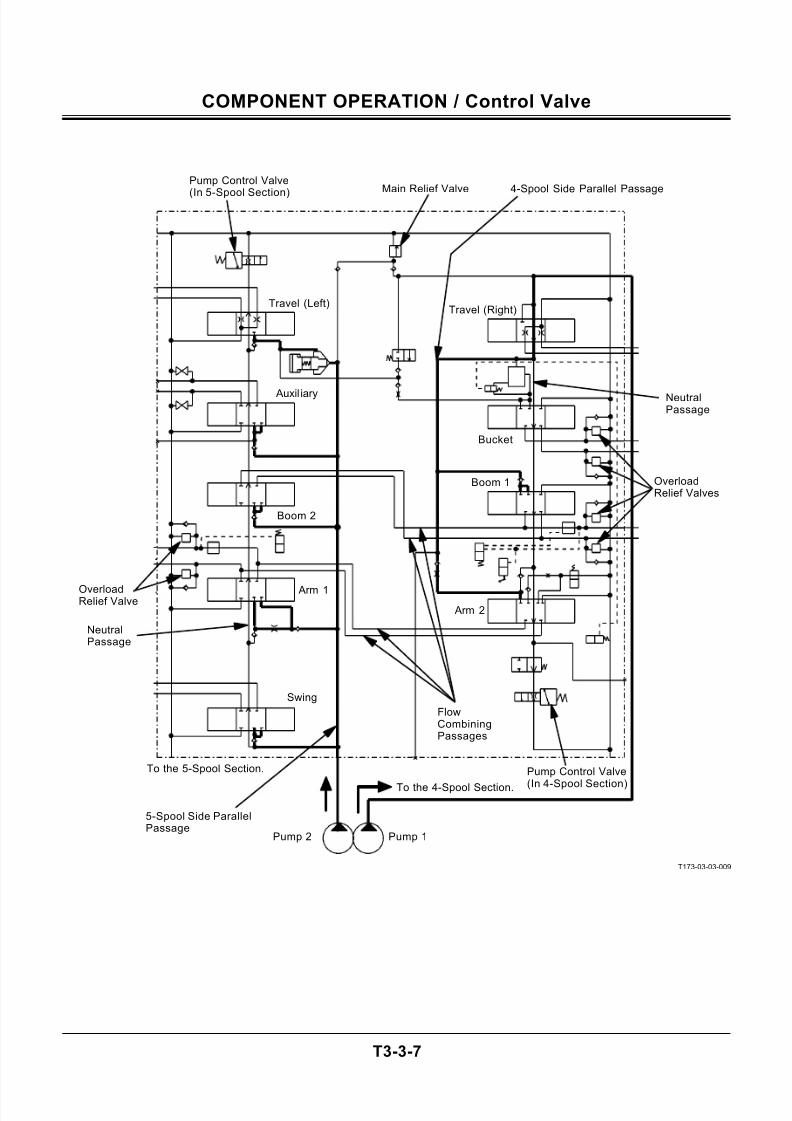
HYDRAULIC CIRCUIT
Main Circuit
1. The pressure oil from pump 1 flows to the travel
(right), the bucket, boom 1, and arm 2 spools in
the 4-spool side control valve.
2. The pressure oil from pump 2 flows to the swing,
arm 1, boom 2, auxiliary, and the travel (left)
spools in the 5-spool side control valve.
3. The main circuits in both the 4 and 5-spool sec-
tions have parallel passages to make combined
operations possible.
4. An oil flow combining passage is provided in both
the boom and the arm circuits so that when a sin-
gle operation is made, the pressure oil from both
pump 1 and 2 is supplied to the boom or the arm
cylinder.5. The pump control valves are provided down
stream of the neutral passages in both the 4 and 5
spool sections.
6. The oil pressure in the main circuit (between the
pump and the actuator) is controlled by the main
relief valve preventing the man circuit oil pressure
from increasing higher than the set pressure.
7. The overload relief valves are located in the boom,
the arm and the bucket actuator circuits between
the control valve and the actuator.
The overload relief valve prevents the surge pres-
sure from being developed by the external loadsin the actuator circuit and prevents the pressure in
the circuit from rising more than the set pressure
when the control spool is in neutral.
7/24/2019 t03 hitachi
http://slidepdf.com/reader/full/t03-hitachi 37/104
COMPONENT OPERATION / Control Valve
T3-3-7
T173-03-03-009
Pump Control Valve
(In 5-Spool Section)
Pump Control Valve
(In 4-Spool Section)
FlowCombiningPassages
Pump 1Pump 2
NeutralPassage
NeutralPassage
Travel (Right)
Swing
Arm 1
Boom 2
Auxil iary
Travel (Left)
Arm 2
Boom 1
Bucket
To the 4-Spool Section.
5-Spool Side ParallelPassage
To the 5-Spool Section.
OverloadRelief Valve
4-Spool Side Parallel PassageMain Relief Valve
OverloadRelief Valves
7/24/2019 t03 hitachi
http://slidepdf.com/reader/full/t03-hitachi 38/104
COMPONENT OPERATION / Control Valve
T3-3-8
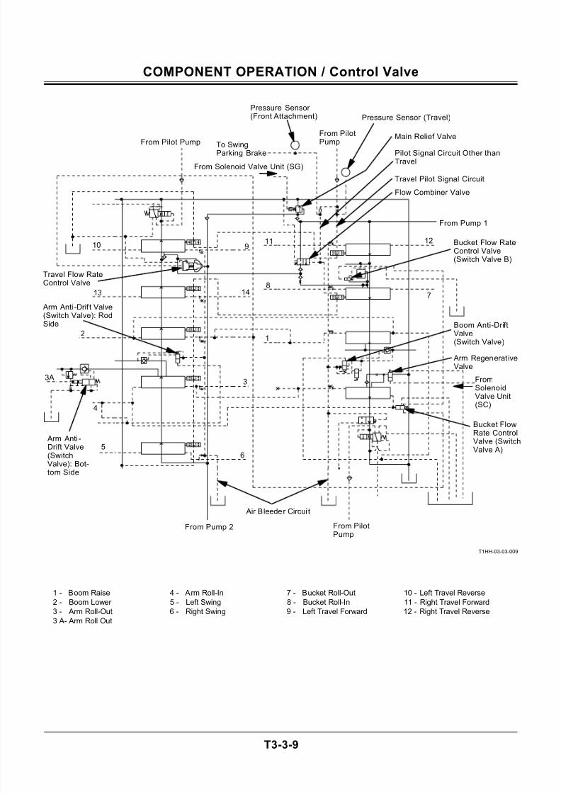
Pilot Control Circuit
The pilot pressure oil (indicated by figures) from the
pilot valve is routed to the end face of each spool in
the control valve so that the spool is operated. While
operating the spools, the pilot pressure oil functions
as follows:
• When raising the boom, pilot pressure oil (1) is
routed to the bucket f low rate control valve (switch
valve B) via the bucket flow rate control valve
(switch valve A) and to the travel flow rate control
valve. Then, both valves are activated.
• When lowering the boom, pilot pressure oil (2) is
routed to activate the boom anti-drift valve (switch
valve).
• When rolling out the arm, pilot pressure oil (3 and
3A) is routed to activate the arm bottom side anti-
drift valve (switch valve).• When rolling in the arm, pilot pressure oil (4) is
routed to activate the arm rod side anti-drift valve
(switch valve) and the bucket flow rate control
valve (switch valve A).
The air bleeder circuit is provided in the upper section
of the control valve so that the air trapped inside the
control valve is automatically exhausted.
Pilot Signal Circuit
The pressure oil from the pilot pump flows through
the control valve as signal pilot pressure. When trav-
eling, the travel spool restricts the signal pilot oil flow,
increasing the circuit pressure. The pressure sensor
(travel) monitors the pressure increase.
When operations other than travel are performed, the
signal pilot pressure circuits other than travel are re-
stricted, increasing the circuit pressure. The pressure
sensor (front attachment) monitors the pressure in-
crease. The flow combiner valve and swing parking
brake switch valve (swing motor) are also operated.
Solenoid Valve Pilot Signal Circuit
• The pilot pressure from solenoid valve unit (SC)
shifts the arm regenerative valve.
• The pilot pressure from solenoid valve unit (SG)increases the pressure setting of the main relief
valve.
(Refer to SYSTEM / Control System group.)
7/24/2019 t03 hitachi
http://slidepdf.com/reader/full/t03-hitachi 39/104
COMPONENT OPERATION / Control Valve
T3-3-9
T1HH-03-03-009
1 - Boom Raise 4 - Arm Roll-In 7 - Bucket Roll-Out 10 - Left Travel Reverse
2 - Boom Lower 5 - Left Swing 8 - Bucket Roll-In 11 - Right Travel Forward
3 - Arm Roll-Out 6 - Right Swing 9 - Left Travel Forward 12 - Right Travel Reverse
3 A- Arm Roll Out
To SwingParking Brake
Pressure Sensor (Front Attachment) Pressure Sensor (Travel)
From Solenoid Valve Unit (SG)
FromSolenoidValve Unit(SC)
From Pump 1
Air Bleeder Circui t
From Pump 2 From PilotPump
From Pilot PumpFrom PilotPump
Flow Combiner Valve
Arm Anti -Drift Valve(SwitchValve): Bot-tom Side
Arm Anti -Drif t Valve(Switch Valve): RodSide
Arm Regenerat iveValve
Boom Anti-DriftValve(Switch Valve)
Main Relief Valve
Bucket FlowRate ControlValve (SwitchValve A)
12
6
3A3
1413
1211910
5
4
7
8Travel Flow RateControl Valve
Bucket Flow RateControl Valve(Switch Valve B)
Pilot Signal Circuit Other thanTravel
Travel Pilot Signal Circuit
7/24/2019 t03 hitachi
http://slidepdf.com/reader/full/t03-hitachi 40/104
COMPONENT OPERATION / Control Valve
T3-3-10
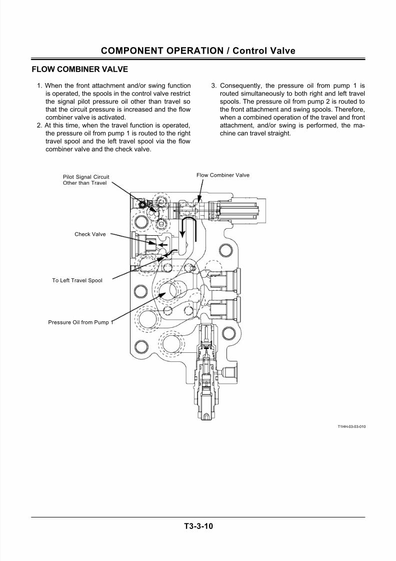
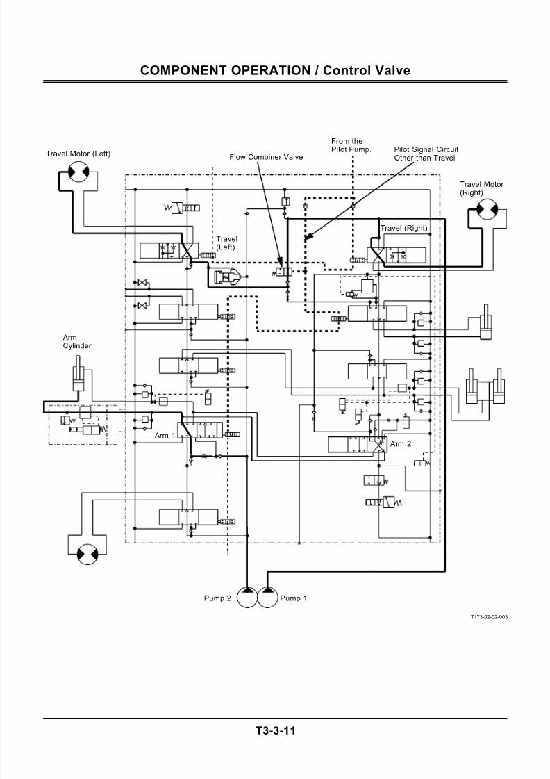
FLOW COMBINER VALVE
1. When the front attachment and/or swing function
is operated, the spools in the control valve restrict
the signal pilot pressure oil other than travel so
that the circuit pressure is increased and the flow
combiner valve is activated.
2. At this time, when the travel function is operated,
the pressure oil from pump 1 is routed to the right
travel spool and the left travel spool via the flow
combiner valve and the check valve.
3. Consequently, the pressure oil from pump 1 is
routed simultaneously to both right and left travel
spools. The pressure oil from pump 2 is routed to
the front attachment and swing spools. Therefore,
when a combined operation of the travel and front
attachment, and/or swing is performed, the ma-
chine can travel straight.
T1HH-03-03-010
Pressure Oil from Pump 1
Flow Combiner Valve
Check Valve
Pilot Signal CircuitOther than Travel
To Left Travel Spool
7/24/2019 t03 hitachi
http://slidepdf.com/reader/full/t03-hitachi 41/104
COMPONENT OPERATION / Control Valve
T3-3-11
T173-02-02-003
Pump 1Pump 2
Arm 2
From thePilot Pump.
Travel (Right)
Travel Motor (Right)
Travel Motor (Left) Flow Combiner Valve
Travel(Left)
ArmCylinder
Arm 1
Pilot Signal CircuitOther than Travel
7/24/2019 t03 hitachi
http://slidepdf.com/reader/full/t03-hitachi 42/104
COMPONENT OPERATION / Control Valve
T3-3-12
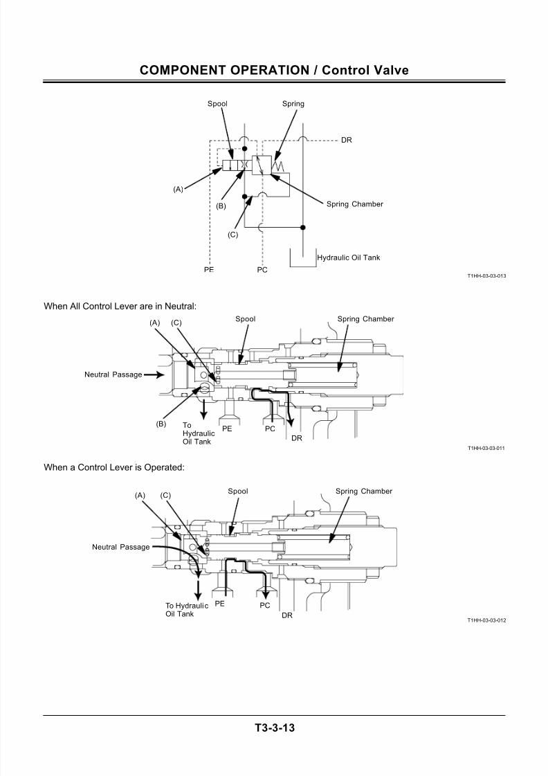
PUMP CONTROL VALVE
The pump control valves are located down stream of
the neutral passages in both the 4 and 5-spool sec-
tions. (Refer to T3-3-7.)
The pump control pressure is regulated by the pump
control valve and is routed to the pump regulator to
control the pump displacement angle. (Refer to the
pump device group.)
The pump control pressure is monitored by the pump
control pressure sensor. Then, the sensing signals are
used to control the travel motor displacement angle.
(Refer to the Control System group in the SYSTEM
section.)
• When All Control Levers are in Neutral:
1. When all control levers are in neutral, the controlvalve neutral passage isn’t restricted as all control
valve spools are in neutral.
2. All oil flow is routed to the hydraulic oil tank from
the neutral passage via spool (B), acting on the
spool (A) in the pump control valve.
3. The oil flow through spool (B) acts on the spring
chamber via spool (C).
4. All oil flow acts on spool (A) in the pump control
vale, so that the force acting on spool (A) over-
comes the spring force and the pressure acting on
the spring chamber through spool (C).
Therefore, the spool in the pump control valvemoves to the right.
5. As connecting port PC and port DR via the spool
notch, the pump control pressure which was
routed to the regulator is returned to the hydraulic
oil tank via port PC.
6. Thus, the pump control pressure is reduced so
that the regulator reduces the pump displacement
angle to the minimum, saving engine fuel con-
sumption.
• When a Control Lever is Operated:
1. When a control lever is operated, the control valve
spool is moved so that the control valve neutralpassage is restricted.
2. In response to the control valve spool, the oil flow
acted on spool (A) in the pump control valve is re-
duced.
3. When the force acting on spool (A) doesn’t over-
come the spring force and the pressure acting on
the spring chamber through spool (C), the spool in
the pump control valve is returned to the left.
4. Then, port PE is connected to port PC via the
spool notch. Thus, the pilot oil pressure is routed
from port PE to the regulator via port PC.
5. When the pump control pressure increases, theregulator increases the pump displacement angle.
7/24/2019 t03 hitachi
http://slidepdf.com/reader/full/t03-hitachi 43/104
COMPONENT OPERATION / Control Valve
T3-3-13
T1HH-03-03-013
When All Control Lever are in Neutral:
T1HH-03-03-011
When a Control Lever is Operated:
T1HH-03-03-012
Neutral Passage
DR
PE PCToHydraulicOil Tank
Spring Chamber
(B)
(A) (C)Spool
DR
PE PC
Spring Chamber Spool
Neutral Passage
Spool
Spring Chamber
Spring
Hydraulic Oil Tank
PCPE
(A)
(B)
(C)
DR
(A) (C)
To HydraulicOil Tank
7/24/2019 t03 hitachi
http://slidepdf.com/reader/full/t03-hitachi 44/104
COMPONENT OPERATION / Control Valve
T3-3-14
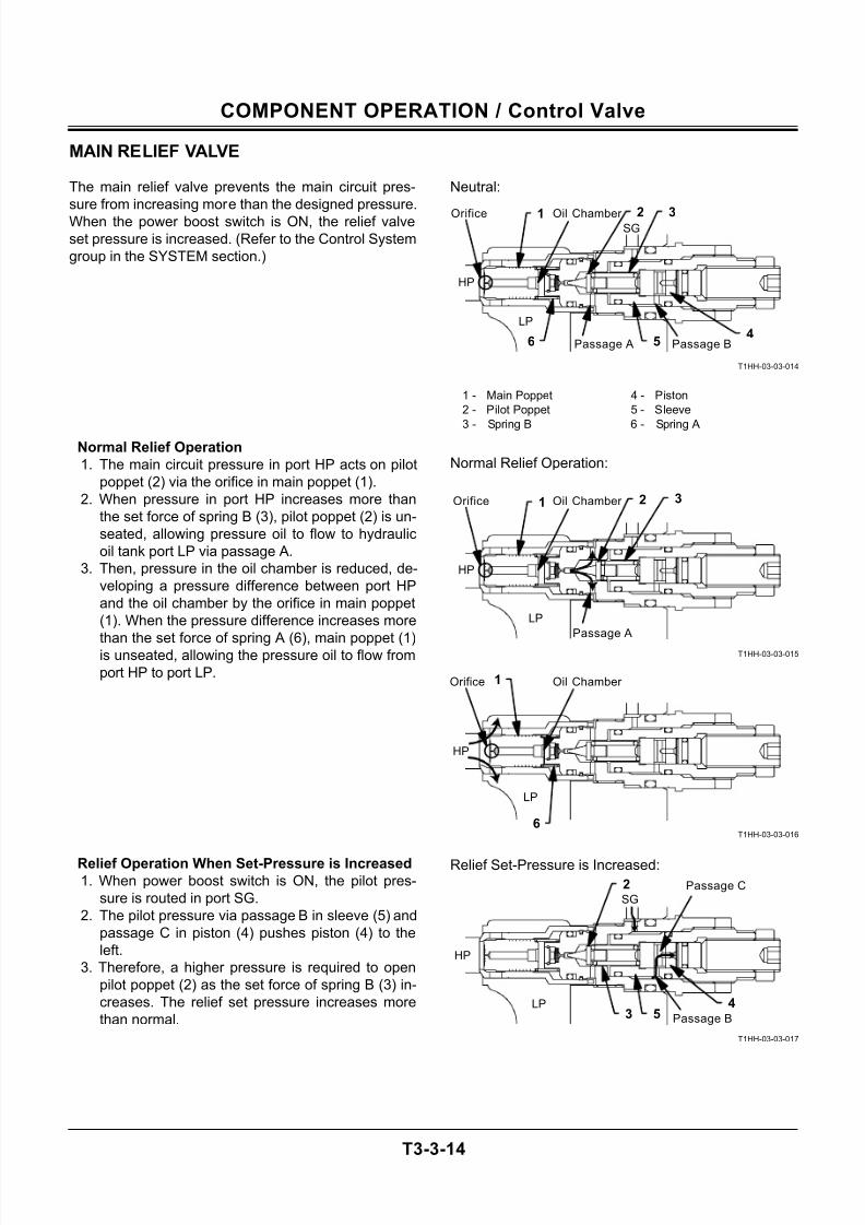
MAIN RELIEF VALVE
The main relief valve prevents the main circuit pres-
sure from increasing more than the designed pressure.
When the power boost switch is ON, the relief valve
set pressure is increased. (Refer to the Control System
group in the SYSTEM section.)
Normal Relief Operation
1. The main circuit pressure in port HP acts on pilot
poppet (2) via the orifice in main poppet (1).
2. When pressure in port HP increases more than
the set force of spring B (3), pilot poppet (2) is un-
seated, allowing pressure oil to flow to hydraulic
oil tank port LP via passage A.
3. Then, pressure in the oil chamber is reduced, de-
veloping a pressure difference between port HP
and the oil chamber by the orifice in main poppet
(1). When the pressure difference increases more
than the set force of spring A (6), main poppet (1)is unseated, allowing the pressure oil to flow from
port HP to port LP.
Relief Operation When Set-Pressure is Increased1. When power boost switch is ON, the pilot pres-
sure is routed in port SG.
2. The pilot pressure via passage B in sleeve (5) and
passage C in piston (4) pushes piston (4) to the
left.
3. Therefore, a higher pressure is required to open
pilot poppet (2) as the set force of spring B (3) in-
creases. The relief set pressure increases more
than normal.
Neutral:
T1HH-03-03-014
1 - Main Poppet 4 - Piston
2 - Pilot Poppet 5 - Sleeve
3 - Spring B 6 - Spring A
Normal Relief Operation:
T1HH-03-03-015
T1HH-03-03-016
Relief Set-Pressure is Increased:
T1HH-03-03-017
LP
SG
HP
1 2
64
5
3
Passage BPassage A
Oil Chamber Orifice
LP
HP
1 2 3
Passage A
Orifice
LP
HP
1Orifice
LP
SG
HP
2
45
Passage C
Passage B
6
3
Oil Chamber
Oil Chamber
7/24/2019 t03 hitachi
http://slidepdf.com/reader/full/t03-hitachi 45/104
COMPONENT OPERATION / Control Valve
T3-3-15
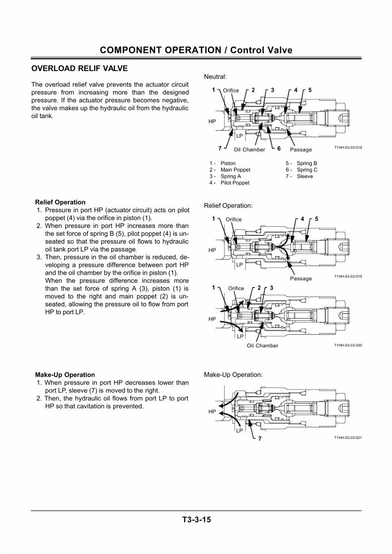
OVERLOAD RELIF VALVE
The overload relief valve prevents the actuator circuit
pressure from increasing more than the designed
pressure. If the actuator pressure becomes negative,
the valve makes up the hydraulic oil from the hydraulic
oil tank.
Relief Operation
1. Pressure in port HP (actuator circuit) acts on pilot
poppet (4) via the orifice in piston (1).
2. When pressure in port HP increases more than
the set force of spring B (5), pilot poppet (4) is un-
seated so that the pressure oil flows to hydraulic
oil tank port LP via the passage.
3. Then, pressure in the oil chamber is reduced, de-
veloping a pressure difference between port HP
and the oil chamber by the orifice in piston (1).
When the pressure difference increases more
than the set force of spring A (3), piston (1) ismoved to the right and main poppet (2) is un-
seated, allowing the pressure oil to flow from port
HP to port LP.
Make-Up Operation
1. When pressure in port HP decreases lower than
port LP, sleeve (7) is moved to the right.2. Then, the hydraulic oil flows from port LP to port
HP so that cavitation is prevented.
Neutral:
T1HH-03-03-018
1 - Piston 5 - Spring B
2 - Main Poppet 6 - Spring C
3 - Spring A 7 - Sleeve
4 - Pilot Poppet
Relief Operation:
T1HH-03-03-019
T1HH-03-03-020
Make-Up Operation:
T1HH-03-03-021
HP
LP
1 2
6
3
PassageOil Chamber
4 5
7
HP
LP
1
Passage
Orifice 4 5
HP
LP
1 2 3
Oil Chamber
Orifice
HP
LP
7
Orifice
7/24/2019 t03 hitachi
http://slidepdf.com/reader/full/t03-hitachi 46/104
COMPONENT OPERATION / Control Valve
T3-3-16
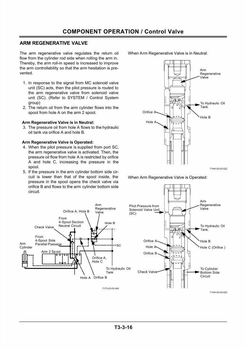
ARM REGENERATIVE VALVE
The arm regenerative valve regulates the return oil
flow from the cylinder rod side when rolling the arm in.
Thereby, the arm roll-in speed is increased to improve
the arm controllability so that the arm hesitation is pre-
vented.
1. In response to the signal from MC solenoid valve
unit (SC) acts, then the pilot pressure is routed to
the arm regenerative valve from solenoid valve
unit (SC). (Refer to SYSTEM / Control System
group)
2. The return oil from the arm cylinder flows into the
spool from hole A on the arm 2 spool.
Arm Regenerative Valve is in Neutral:3. The pressure oil from hole A flows to the hydraulic
oil tank via orifice A and hole B.
Arm Regenerative Valve is Operated:
4. When the pilot pressure is supplied from port SC,
the arm regenerative valve is activated. Then, the
pressure oil flow from hole A is restricted by orifice
A and hole C, increasing the pressure in the
spool.
5. If the pressure in the arm cylinder bottom side cir-
cuit is lower than that of the spool inside, the
pressure in the spool opens the check valve viaorifice B and flows to the arm cylinder bottom side
circuit.
T173-03-03-049
When Arm Regenerative Valve is in Neutral:
T1HH-03-03-022
When Arm Regenerative Valve is Operated:
T1HH-03-03-023
Hole B
Hole A
To Hydraulic OilTank.
Pilot Pressure fromSolenoid Valve Unit(SC)
Hole B
Hole A
To Hydraulic OilTank.
Hole C (Orifice )
Orifice A
Orifice B
Orifice A
Check ValveTo Cylinder Bottom SideCircuit
ArmRegenerativeValve
ArmRegenerativeValve
To Hydraulic OilTank
Arm 2 Spool
ArmCylinder
From4-Spool SectionNeutral Circuit
From4-Spool Side
Parallel Passage
ArmRegenerativeValve
SC
Hole A
Orifice A,Hole C
Orifice B
Orifice A, Hole B
Check Valve
Hole B
7/24/2019 t03 hitachi
http://slidepdf.com/reader/full/t03-hitachi 47/104
COMPONENT OPERATION / Control Valve
T3-3-17
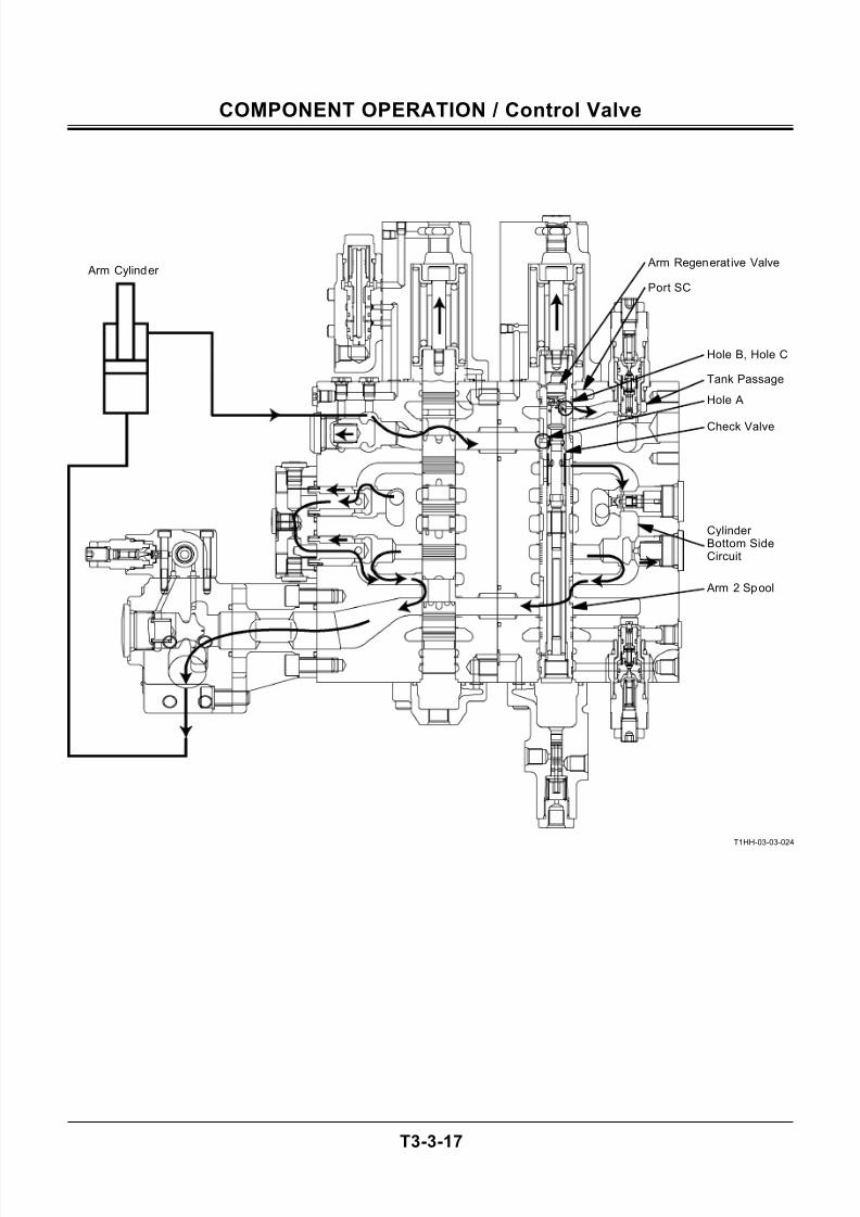
T1HH-03-03-024
Check Valve
Port SC
Arm Cylinder Arm Regenerat ive Valve
Hole B, Hole C
Tank Passage
Hole A
Cylinder Bottom SideCircuit
Arm 2 Spool
7/24/2019 t03 hitachi
http://slidepdf.com/reader/full/t03-hitachi 48/104
COMPONENT OPERATION / Control Valve
T3-3-18
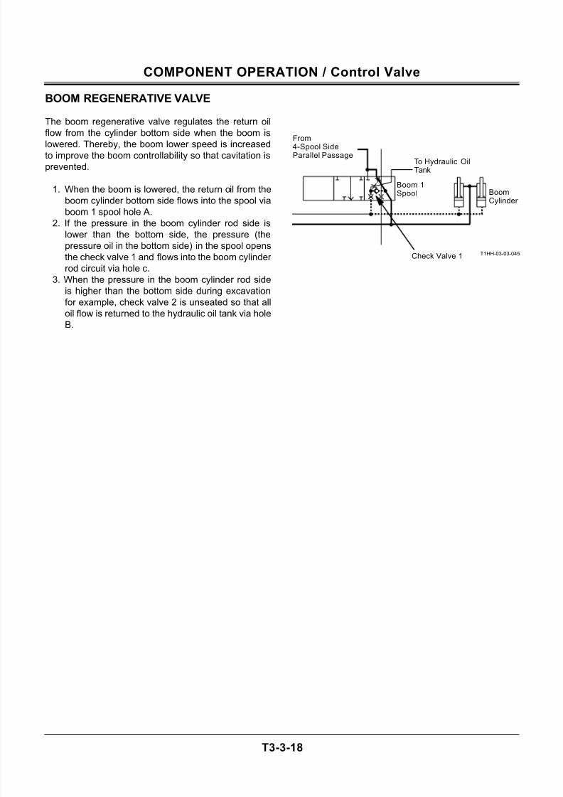
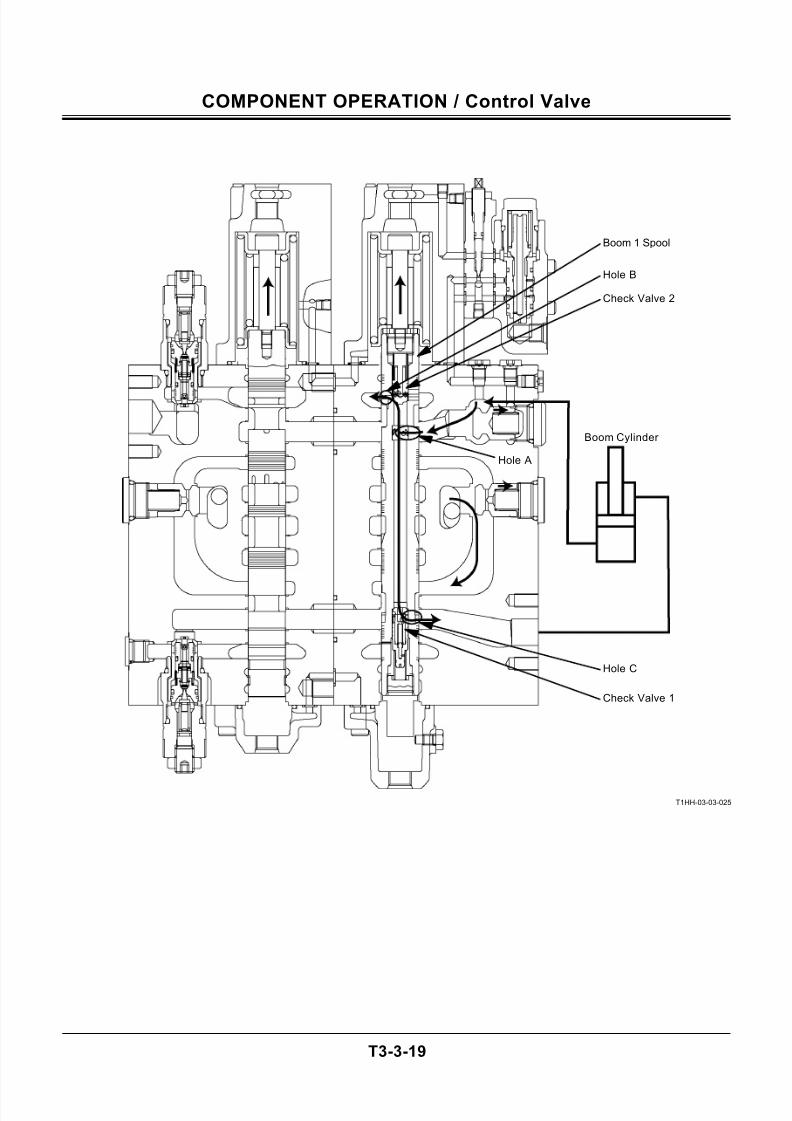
BOOM REGENERATIVE VALVE
The boom regenerative valve regulates the return oil
flow from the cylinder bottom side when the boom is
lowered. Thereby, the boom lower speed is increased
to improve the boom controllability so that cavitation is
prevented.
1. When the boom is lowered, the return oil from the
boom cylinder bottom side flows into the spool via
boom 1 spool hole A.
2. If the pressure in the boom cylinder rod side is
lower than the bottom side, the pressure (the
pressure oil in the bottom side) in the spool opens
the check valve 1 and flows into the boom cylinder
rod circuit via hole c.
3. When the pressure in the boom cylinder rod sideis higher than the bottom side during excavation
for example, check valve 2 is unseated so that all
oil flow is returned to the hydraulic oil tank via hole
B.
T1HH-03-03-045
From4-Spool SideParallel Passage
BoomCylinder
Boom 1Spool
To Hydraulic OilTank
Check Valve 1
7/24/2019 t03 hitachi
http://slidepdf.com/reader/full/t03-hitachi 49/104
COMPONENT OPERATION / Control Valve
T3-3-19
T1HH-03-03-025
Hole A
Hole C
Check Valve 1
Hole B
Check Valve 2
Boom Cylinder
Boom 1 Spool
7/24/2019 t03 hitachi
http://slidepdf.com/reader/full/t03-hitachi 50/104
COMPONENT OPERATION / Control Valve
T3-3-20
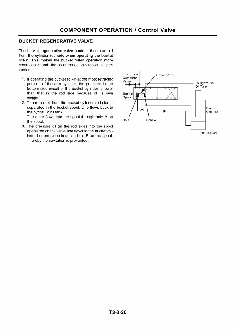
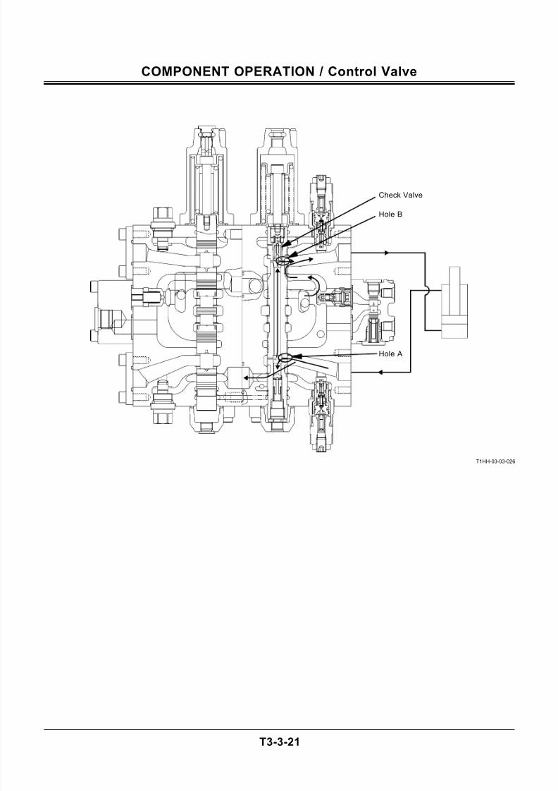
BUCKET REGENERATIVE VALVE
The bucket regenerative valve controls the return oil
from the cylinder rod side when operating the bucket
roll-in. This makes the bucket roll-in operation more
controllable and the occurrence cavitation is pre-
vented.
1. If operating the bucket roll-in at the most retracted
position of the arm cylinder, the pressure in the
bottom side circuit of the bucket cylinder is lower
than that in the rod side because of its own
weight.
2. The return oil from the bucket cylinder rod side is
separated in the bucket spool. One flows back to
the hydraulic oil tank.
The other flows into the spool through hole A onthe spool.
3. The pressure oil (in the rod side) into the spool
opens the check valve and flows to the bucket cyl-
inder bottom side circuit via hole B on the spool.
Thereby the cavitation is prevented.
T1HH-03-03-027
Check Valve
To HydraulicOil Tank
From FlowCombiner Valve
BucketSpool
Hole B Hole A
BucketCylinder
7/24/2019 t03 hitachi
http://slidepdf.com/reader/full/t03-hitachi 51/104
COMPONENT OPERATION / Control Valve
T3-3-21
T1HH-03-03-026
Hole A
Hole B
Check Valve
7/24/2019 t03 hitachi
http://slidepdf.com/reader/full/t03-hitachi 52/104
COMPONENT OPERATION / Control Valve
T3-3-22
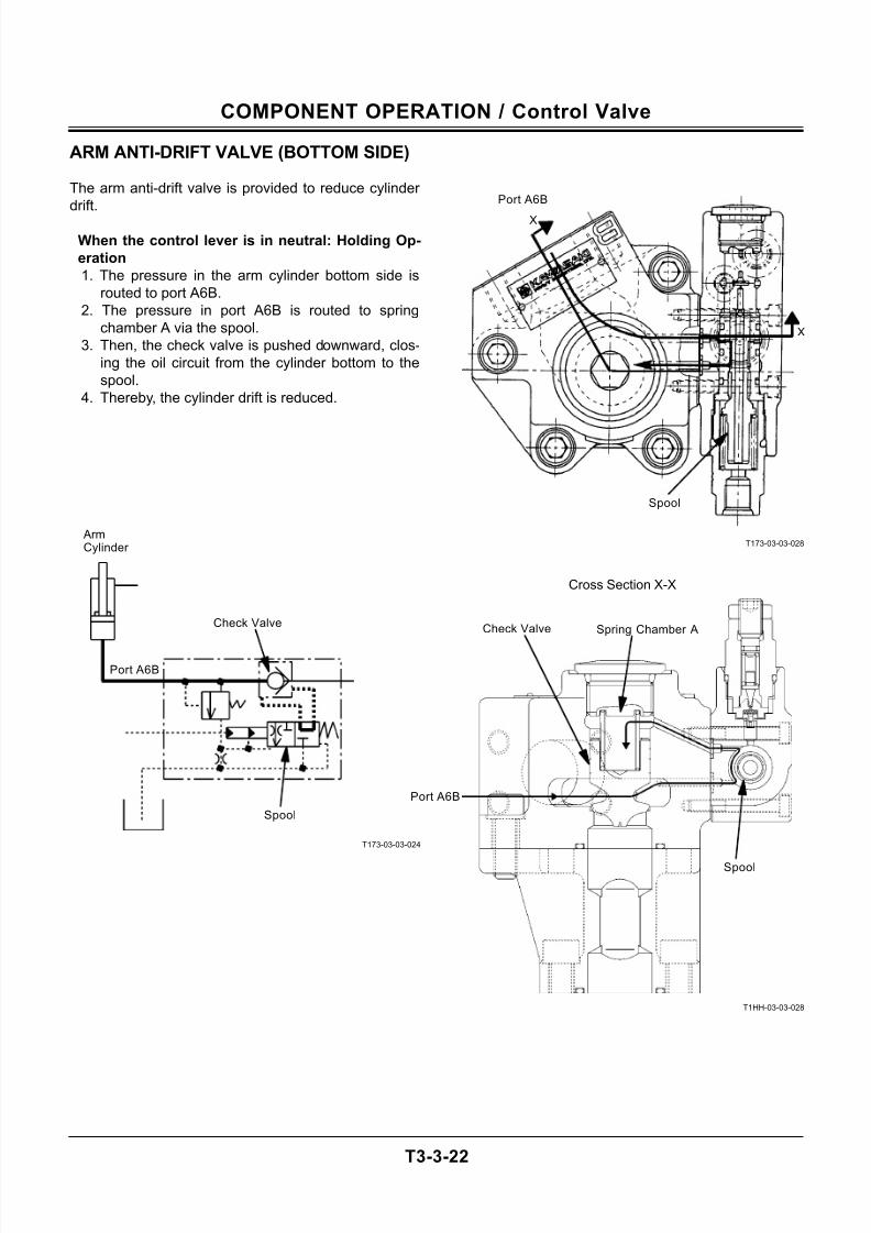
ARM ANTI-DRIFT VALVE (BOTTOM SIDE)
The arm anti-drift valve is provided to reduce cylinder
drift.
When the control lever is in neutral: Holding Op-
eration
1. The pressure in the arm cylinder bottom side is
routed to port A6B.
2. The pressure in port A6B is routed to spring
chamber A via the spool.
3. Then, the check valve is pushed downward, clos-
ing the oil circuit from the cylinder bottom to the
spool.
4. Thereby, the cylinder drift is reduced.
T173-03-03-024
T173-03-03-028
T1HH-03-03-028
X
Cross Section X-X
Spool
Port A6B
Port A6B
Spring Chamber A
Spool
Check Valve
Spool
ArmCylinder
Port A6B
Check Valve
X
7/24/2019 t03 hitachi
http://slidepdf.com/reader/full/t03-hitachi 53/104
COMPONENT OPERATION / Control Valve
T3-3-23
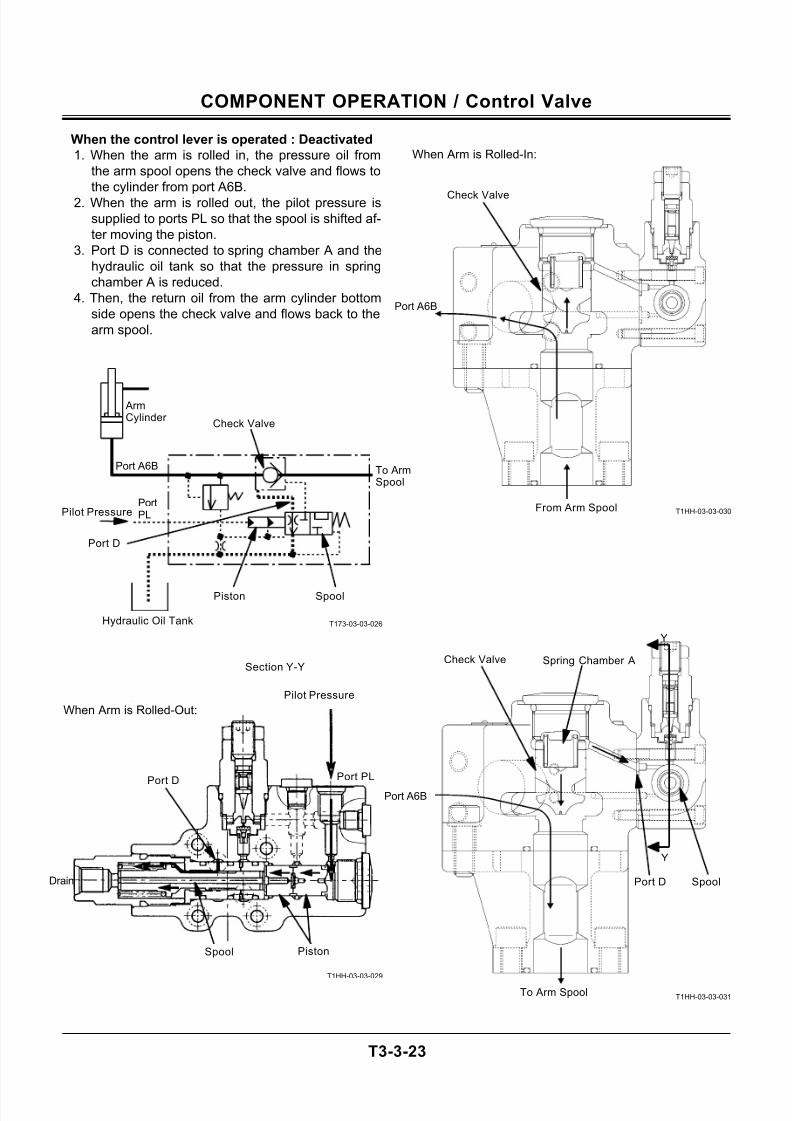
When the control lever is operated : Deactivated
1. When the arm is rolled in, the pressure oil from
the arm spool opens the check valve and flows to
the cylinder from port A6B.
2. When the arm is rolled out, the pilot pressure is
supplied to ports PL so that the spool is shifted af-
ter moving the piston.
3. Port D is connected to spring chamber A and the
hydraulic oil tank so that the pressure in spring
chamber A is reduced.
4. Then, the return oil from the arm cylinder bottom
side opens the check valve and flows back to the
arm spool.
T173-03-03-026
T1HH-03-03-029
T1HH-03-03-030
T1HH-03-03-031
When Arm is Rolled-In:
Port A6B
From Arm Spool
Check Valve
When Arm is Rolled-Out:
Pilot Pressure
Piston
Port D
Section Y-Y
Port PL
Drain
Check Valve
Spool
To ArmSpool
Port A6B
To Arm Spool
Spool
ArmCylinder
PortPL
Port A6B
Spool
Check Valve
Port D
Hydraulic Oil Tank
Pilot Pressure
Port D
Piston
Spring Chamber A
Y
Y
7/24/2019 t03 hitachi
http://slidepdf.com/reader/full/t03-hitachi 54/104
COMPONENT OPERATION / Control Valve
T3-3-24
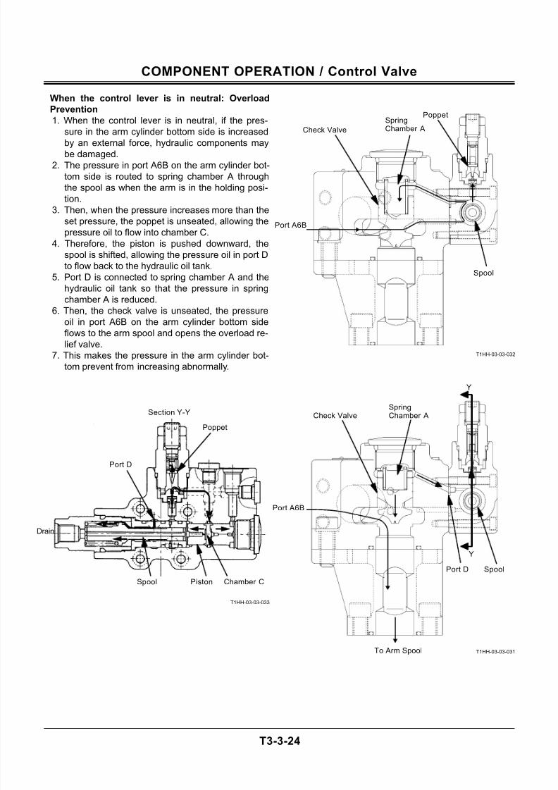
When the control lever is in neutral: Overload
Prevention
1. When the control lever is in neutral, if the pres-
sure in the arm cylinder bottom side is increased
by an external force, hydraulic components may
be damaged.
2. The pressure in port A6B on the arm cylinder bot-
tom side is routed to spring chamber A through
the spool as when the arm is in the holding posi-
tion.
3. Then, when the pressure increases more than the
set pressure, the poppet is unseated, allowing the
pressure oil to flow into chamber C.
4. Therefore, the piston is pushed downward, the
spool is shifted, allowing the pressure oil in port D
to flow back to the hydraulic oil tank.
5. Port D is connected to spring chamber A and thehydraulic oil tank so that the pressure in spring
chamber A is reduced.
6. Then, the check valve is unseated, the pressure
oil in port A6B on the arm cylinder bottom side
flows to the arm spool and opens the overload re-
lief valve.
7. This makes the pressure in the arm cylinder bot-
tom prevent from increasing abnormally.
T1HH-03-03-033
T1HH-03-03-032
T1HH-03-03-031
Spool Piston
Port D
Drain
Port A6B
Spool
Port A6B
To Arm Spool
Section Y-Y
Poppet
Poppet
Chamber C
Y
Y
Check Valve
Spring
Chamber A
SpoolPort D
Check Valve
SpringChamber A
7/24/2019 t03 hitachi
http://slidepdf.com/reader/full/t03-hitachi 55/104
COMPONENT OPERATION / Control Valve
T3-3-25
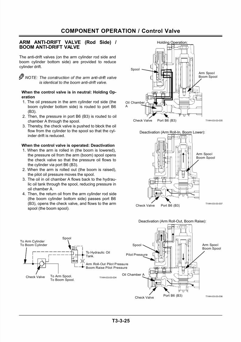
ARM ANTI-DRIFT VALVE (Rod Side) /BOOM ANTI-DRIFT VALVE
The anti-drift valves (on the arm cylinder rod side and
boom cylinder bottom side) are provided to reduce
cylinder drift.
NOTE: The construction of the arm anti-drift valve
is identical to the boom anti-drift valve.
When the control valve is in neutral: Holding Op-
eration
1. The oil pressure in the arm cylinder rod side (the
boom cylinder bottom side) is routed to port B6
(B3).
2. Then, the pressure in port B6 (B3) is routed to oil
chamber A through the spool.3. Thereby, the check valve is pushed to block the oil
flow from the cylinder to the spool so that the cyl-
inder drift is reduced.
When the control valve is operated: Deactivation
1. When the arm is rolled in (the boom is lowered),
the pressure oil from the arm (boom) spool opens
the check valve so that the pressure oil flows to
the cylinder via port B6 (B3).
2. When the arm is rolled out (the boom is raised),
the pilot oil pressure moves the spool.
3. The oil in oil chamber A flows back to the hydrau-lic oil tank through the spool, reducing pressure in
oil chamber A.
4. Then, the return oil from the arm cylinder rod side
(the boom cylinder bottom side) passes port B6
(B3), opens the check valve, and flows to the arm
spool (the boom spool).
T1HH-03-03-034
T1HH-03-03-035
T1HH-03-03-037
T1HH-03-03-036
Deactivation (Arm Roll-In, Boom Lower):
Deactivation (Arm Roll-Out, Boom Raise):
Arm SpoolBoom Spool
Port B6 (B3)
Spool
Oil Chamber A
Check Valve
Holding Operation:
Check Valve
To Arm Cylinder To Boom Cylinder
To Hydraulic OilTank.
Arm Roll-Out Pilot PressureBoom Raise Pilot Pressure
To Arm Spool.To Boom Spool.
Spool
Arm SpoolBoom Spool
Port B6 (B3)Check Valve
Pilot Pressure
Arm SpoolBoom Spool
Port B6 (B3)
Spool
Oil Chamber A
Check Valve
7/24/2019 t03 hitachi
http://slidepdf.com/reader/full/t03-hitachi 56/104
COMPONENT OPERATION / Control Valve
T3-3-26
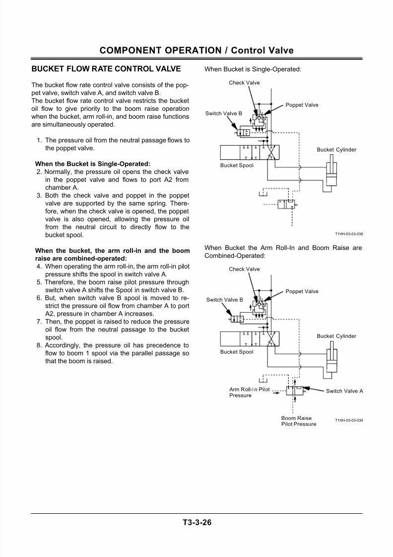
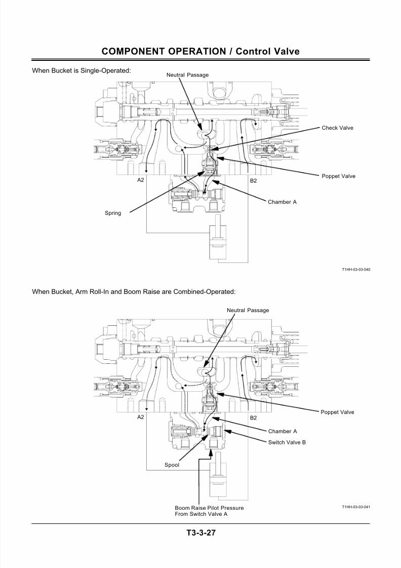
BUCKET FLOW RATE CONTROL VALVE
The bucket flow rate control valve consists of the pop-
pet valve, switch valve A, and switch valve B.
The bucket flow rate control valve restricts the bucket
oil flow to give priority to the boom raise operation
when the bucket, arm roll-in, and boom raise functions
are simultaneously operated.
1. The pressure oil from the neutral passage flows to
the poppet valve.
When the Bucket is Single-Operated:
2. Normally, the pressure oil opens the check valve
in the poppet valve and flows to port A2 from
chamber A.
3. Both the check valve and poppet in the poppetvalve are supported by the same spring. There-
fore, when the check valve is opened, the poppet
valve is also opened, allowing the pressure oil
from the neutral circuit to directly flow to the
bucket spool.
When the bucket, the arm roll-in and the boom
raise are combined-operated:
4. When operating the arm roll-in, the arm roll-in pilot
pressure shifts the spool in switch valve A.
5. Therefore, the boom raise pilot pressure through
switch valve A shifts the Spool in switch valve B.6. But, when switch valve B spool is moved to re-
strict the pressure oil flow from chamber A to port
A2, pressure in chamber A increases.
7. Then, the poppet is raised to reduce the pressure
oil flow from the neutral passage to the bucket
spool.
8. Accordingly, the pressure oil has precedence to
flow to boom 1 spool via the parallel passage so
that the boom is raised.
When Bucket is Single-Operated:
T1HH-03-03-038
When Bucket the Arm Roll-In and Boom Raise are
Combined-Operated:
T1HH-03-03-039
Bucket Cylinder
Bucket Spool
Check Valve
Poppet Valve
Switch Valve B
Boom RaisePilot Pressure
Arm Roll-In PilotPressure
Check Valve
Poppet Valve
Switch Valve A
Switch Valve B
Bucket Cylinder
Bucket Spool
7/24/2019 t03 hitachi
http://slidepdf.com/reader/full/t03-hitachi 57/104
COMPONENT OPERATION / Control Valve
T3-3-27
When Bucket is Single-Operated:
T1HH-03-03-040
When Bucket, Arm Roll-In and Boom Raise are Combined-Operated:
T1HH-03-03-041
B2 A2
Chamber A
Poppet Valve
Check Valve
Spring
Neutral Passage
B2 A2
Chamber A
Boom Raise Pilot PressureFrom Switch Valve A
Poppet Valve
Spool
Neutral Passage
Switch Valve B
7/24/2019 t03 hitachi
http://slidepdf.com/reader/full/t03-hitachi 58/104
COMPONENT OPERATION / Control Valve
T3-3-28
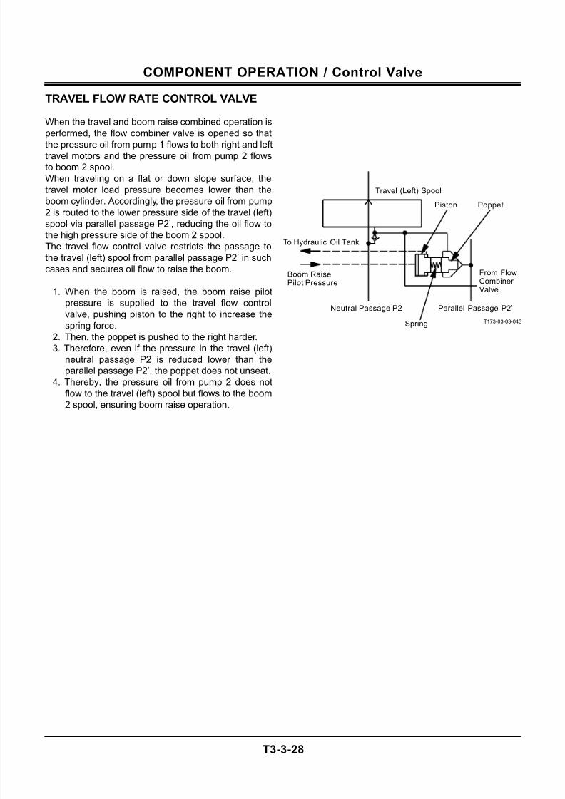
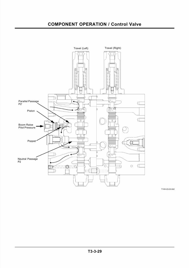
TRAVEL FLOW RATE CONTROL VALVE
When the travel and boom raise combined operation is
performed, the flow combiner valve is opened so that
the pressure oil from pump 1 flows to both right and left
travel motors and the pressure oil from pump 2 flows
to boom 2 spool.
When traveling on a flat or down slope surface, the
travel motor load pressure becomes lower than the
boom cylinder. Accordingly, the pressure oil from pump
2 is routed to the lower pressure side of the travel (left)
spool via parallel passage P2’, reducing the oil flow to
the high pressure side of the boom 2 spool.
The travel flow control valve restricts the passage to
the travel (left) spool from parallel passage P2’ in such
cases and secures oil flow to raise the boom.
1. When the boom is raised, the boom raise pilot
pressure is supplied to the travel flow control
valve, pushing piston to the right to increase the
spring force.
2. Then, the poppet is pushed to the right harder.
3. Therefore, even if the pressure in the travel (left)
neutral passage P2 is reduced lower than the
parallel passage P2’, the poppet does not unseat.
4. Thereby, the pressure oil from pump 2 does not
flow to the travel (left) spool but flows to the boom
2 spool, ensuring boom raise operation.
T173-03-03-043
Boom RaisePilot Pressure
Travel (Left) Spool
Piston
From Flow
Combiner Valve
Parallel Passage P2’Neutral Passage P2
To Hydraulic Oil Tank
Poppet
Spring
7/24/2019 t03 hitachi
http://slidepdf.com/reader/full/t03-hitachi 59/104
COMPONENT OPERATION / Control Valve
T3-3-29
T1HH-03-03-042
Neutral PassageP2
Parallel PassageP2’
Travel (Right)Travel (Left)
Piston
Boom RaisePilot Pressure
Poppet
7/24/2019 t03 hitachi
http://slidepdf.com/reader/full/t03-hitachi 60/104
COMPONENT OPERATION / Control Valve
T3-3-30
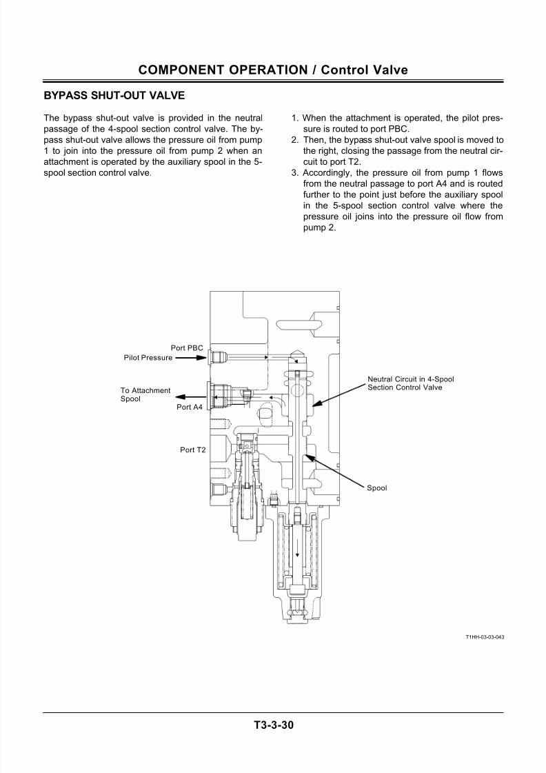
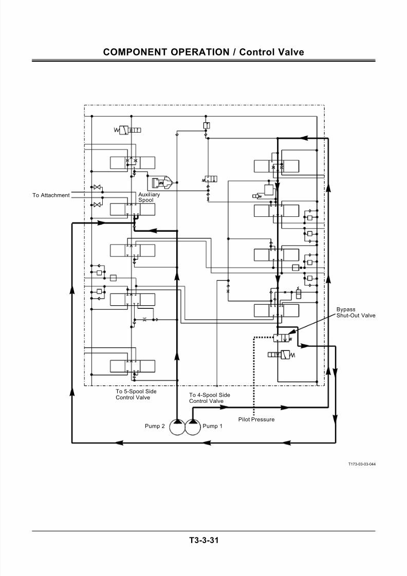
BYPASS SHUT-OUT VALVE
The bypass shut-out valve is provided in the neutral
passage of the 4-spool section control valve. The by-
pass shut-out valve allows the pressure oil from pump
1 to join into the pressure oil from pump 2 when an
attachment is operated by the auxiliary spool in the 5-
spool section control valve.
1. When the attachment is operated, the pilot pres-
sure is routed to port PBC.
2. Then, the bypass shut-out valve spool is moved to
the right, closing the passage from the neutral cir-
cuit to port T2.
3. Accordingly, the pressure oil from pump 1 flows
from the neutral passage to port A4 and is routed
further to the point just before the auxiliary spool
in the 5-spool section control valve where the
pressure oil joins into the pressure oil flow from
pump 2.
T1HH-03-03-043
To AttachmentSpool
Spool
Port PBC
Port A4
Port T2
Pilot Pressure
Neutral Circuit in 4-SpoolSection Control Valve
7/24/2019 t03 hitachi
http://slidepdf.com/reader/full/t03-hitachi 61/104
COMPONENT OPERATION / Control Valve
T3-3-31
T173-03-03-044
Pump 2
BypassShut-Out Valve
To 5-Spool SideControl Valve To 4-Spool Side
Control Valve
Pilot Pressure
Pump 1
Auxil iary
Spool
To Attachment
7/24/2019 t03 hitachi
http://slidepdf.com/reader/full/t03-hitachi 62/104
COMPONENT OPERATION / Control Valve
T3-3-32
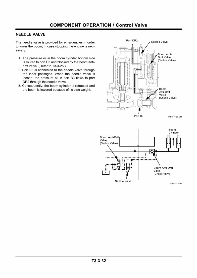
NEEDLE VALVE
The needle valve is provided for emergencies in order
to lower the boom, in case stopping the engine is nec-
essary.
1. The pressure oil in the boom cylinder bottom side
is routed to port B3 and blocked by the boom anti-
drift valve. (Refer to T3-3-25.)
2. Port B3 is connected to the needle valve through
the inner passages. When the needle valve is
loosen, the pressure oil in port B3 flows to port
DR2 through the needle valve.
3. Consequently, the boom cylinder is retracted and
the boom is lowered because of its own weight.
T1HH-03-03-044
T173-03-03-046
Port DR2
Port B3
Needle Valve
Boom Anti-Drift Valve(Switch Valve)
Boom Anti -DriftValve
(Check Valve)
Boom Anti-DriftValve(Check Valve)
Boom Anti-DriftValve(Switch Valve)
BoomCylinder
Needle Valve
7/24/2019 t03 hitachi
http://slidepdf.com/reader/full/t03-hitachi 63/104
COMPONENT OPERATION / Pilot Valve
T3-4-1
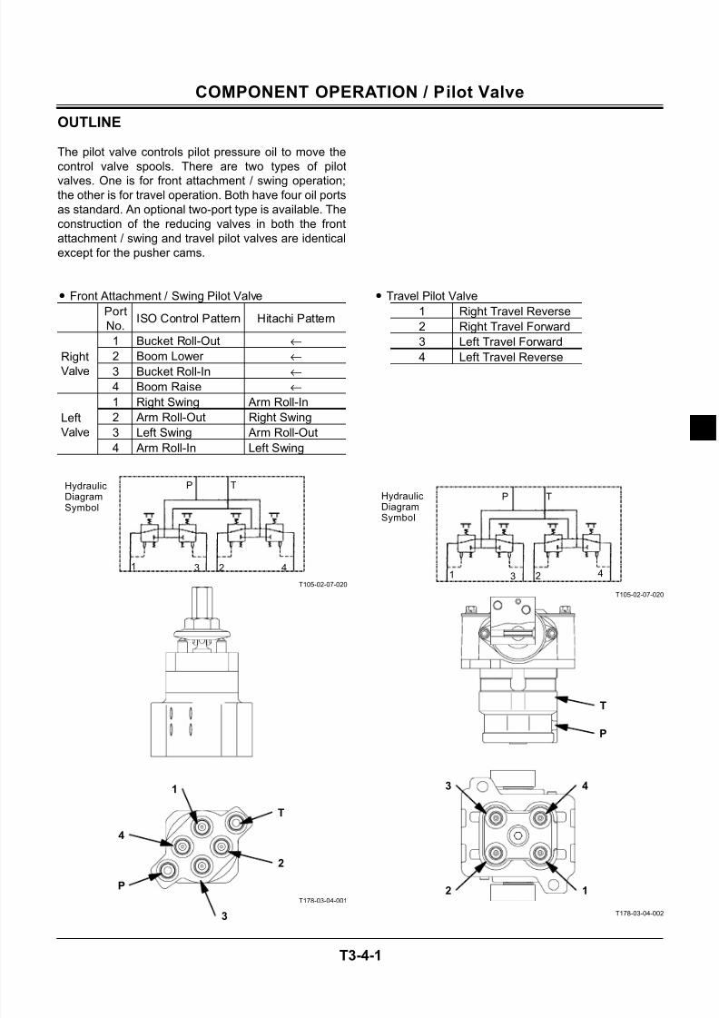
OUTLINE
The pilot valve controls pilot pressure oil to move the
control valve spools. There are two types of pilot
valves. One is for front attachment / swing operation;the other is for travel operation. Both have four oil ports
as standard. An optional two-port type is available. The
construction of the reducing valves in both the front
attachment / swing and travel pilot valves are identical
except for the pusher cams.
• Front Attachment / Swing Pilot Valve
Port
No.ISO Control Pattern Hitachi Pattern
1 Bucket Roll-Out ←
2 Boom Lower ←
3 Bucket Roll-In ←
RightValve
4 Boom Raise ←
1 Right Swing Arm Roll-In
2 Arm Roll-Out Right Swing
3 Left Swing Arm Roll-Out
Left
Valve
4 Arm Roll-In Left Swing
T105-02-07-020
T178-03-04-001
• Travel Pilot Valve
1 Right Travel Reverse
2 Right Travel Forward
3 Left Travel Forward
4 Left Travel Reverse
T105-02-07-020
T178-03-04-002
HydraulicDiagramSymbol
4231
TP
4
1
2
T
3
2
1
3
T
P
P
4
4
1
3
2
P
T
HydraulicDiagramSymbol
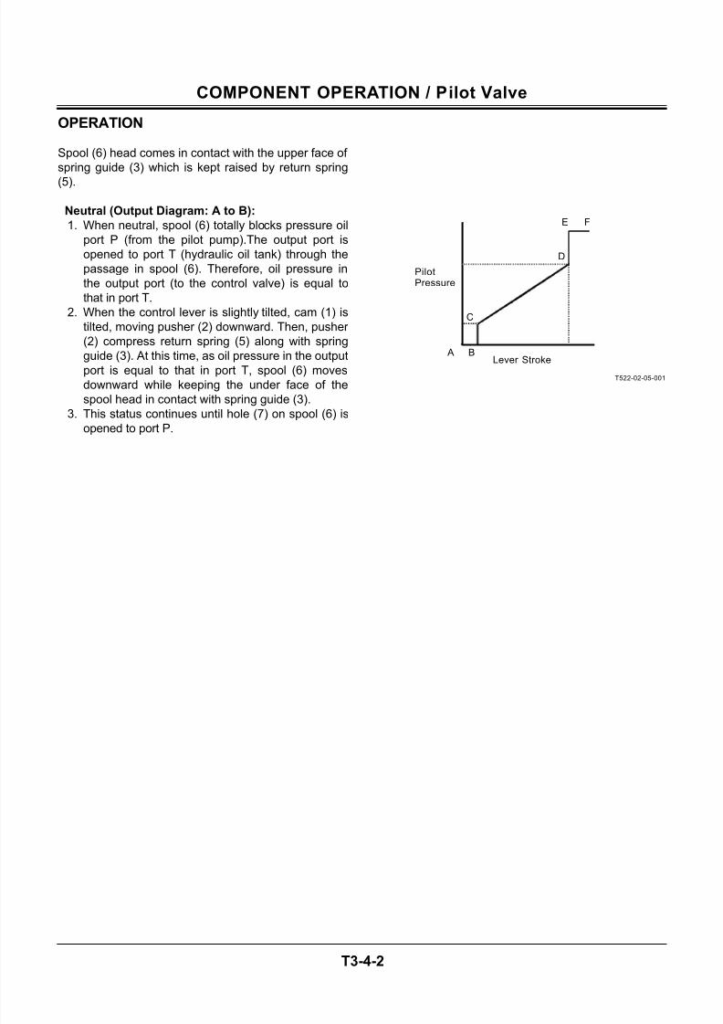
7/24/2019 t03 hitachi
http://slidepdf.com/reader/full/t03-hitachi 64/104
COMPONENT OPERATION / Pilot Valve
T3-4-2
OPERATION
Spool (6) head comes in contact with the upper face of
spring guide (3) which is kept raised by return spring
(5).
Neutral (Output Diagram: A to B):
1. When neutral, spool (6) totally blocks pressure oil
port P (from the pilot pump).The output port is
opened to port T (hydraulic oil tank) through the
passage in spool (6). Therefore, oil pressure in
the output port (to the control valve) is equal to
that in port T.
2. When the control lever is slightly tilted, cam (1) is
tilted, moving pusher (2) downward. Then, pusher
(2) compress return spring (5) along with spring
guide (3). At this time, as oil pressure in the outputport is equal to that in port T, spool (6) moves
downward while keeping the under face of the
spool head in contact with spring guide (3).
3. This status continues until hole (7) on spool (6) is
opened to port P.
T522-02-05-001
PilotPressure
FE
D
C
B ALever Stroke
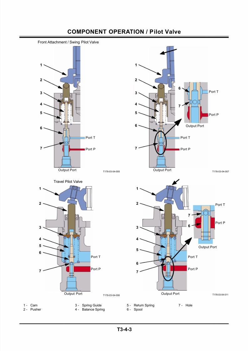
7/24/2019 t03 hitachi
http://slidepdf.com/reader/full/t03-hitachi 65/104
COMPONENT OPERATION / Pilot Valve
T3-4-3
T178-03-04-005
T178-03-04-006
T178-03-04-007
T178-03-04-011
1 - Cam 3 - Spring Guide 5 - Return Spring 7 - Hole
2 - Pusher 4 - Balance Spring 6 - Spool
Front Attachment / Swing Pilot Valve
1
2
3
4
6
5
7
Output Port
Port P
Port T
Travel Pilot Valve
1
2
3
4
6
5
7
Output Port
Output Port
Port P
Port T
1
2
3
4
5
7
Output Port
Port P
Port T
1
2
3
4
6
5
7
Output Port
Output Port
Port P
Port T
6
Port P
Port T6
7
Port P
Port T
7
6
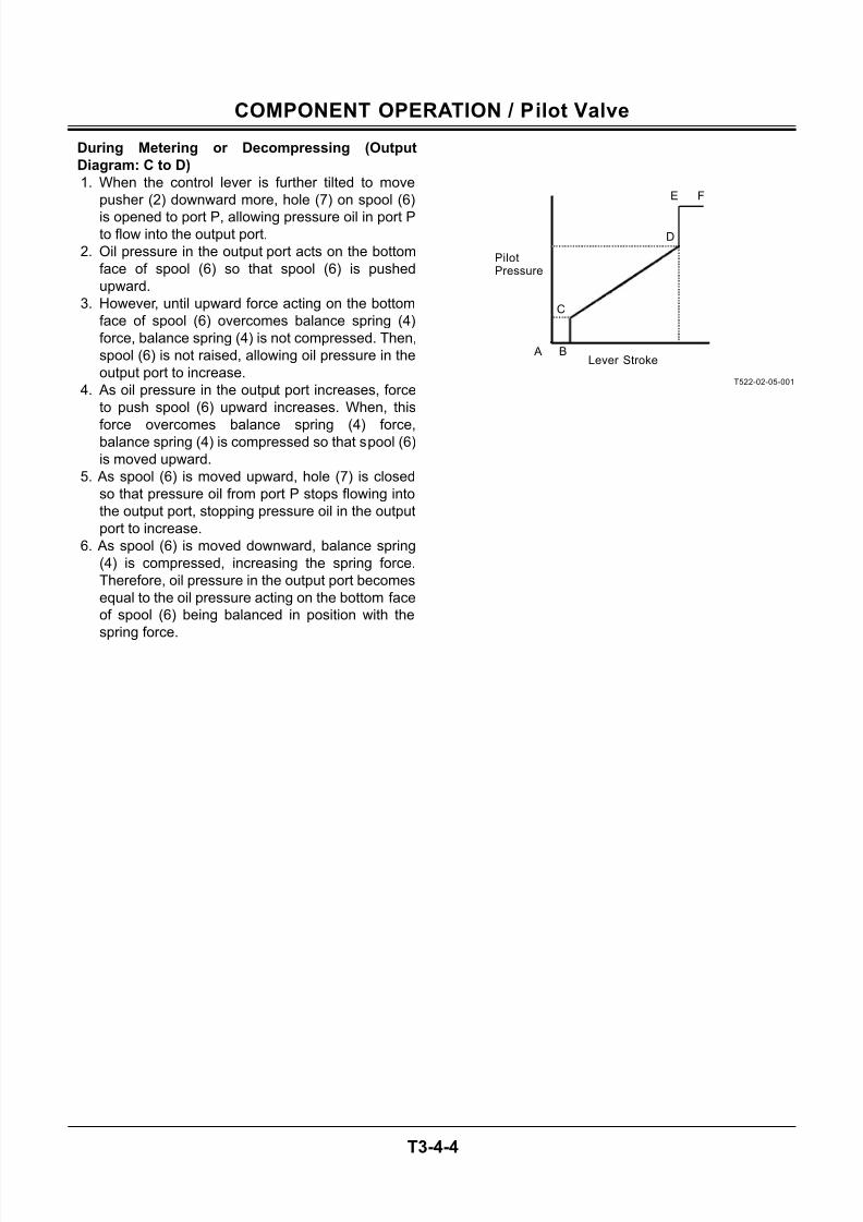
7/24/2019 t03 hitachi
http://slidepdf.com/reader/full/t03-hitachi 66/104
COMPONENT OPERATION / Pilot Valve
T3-4-4
During Metering or Decompressing (Output
Diagram: C to D)
1. When the control lever is further tilted to move
pusher (2) downward more, hole (7) on spool (6)
is opened to port P, allowing pressure oil in port Pto flow into the output port.
2. Oil pressure in the output port acts on the bottom
face of spool (6) so that spool (6) is pushed
upward.
3. However, until upward force acting on the bottom
face of spool (6) overcomes balance spring (4)
force, balance spring (4) is not compressed. Then,
spool (6) is not raised, allowing oil pressure in the
output port to increase.
4. As oil pressure in the output port increases, force
to push spool (6) upward increases. When, this
force overcomes balance spring (4) force,balance spring (4) is compressed so that spool (6)
is moved upward.
5. As spool (6) is moved upward, hole (7) is closed
so that pressure oil from port P stops flowing into
the output port, stopping pressure oil in the output
port to increase.
6. As spool (6) is moved downward, balance spring
(4) is compressed, increasing the spring force.
Therefore, oil pressure in the output port becomes
equal to the oil pressure acting on the bottom face
of spool (6) being balanced in position with the
spring force.
T522-02-05-001
PilotPressure
FE
D
C
B ALever Stroke
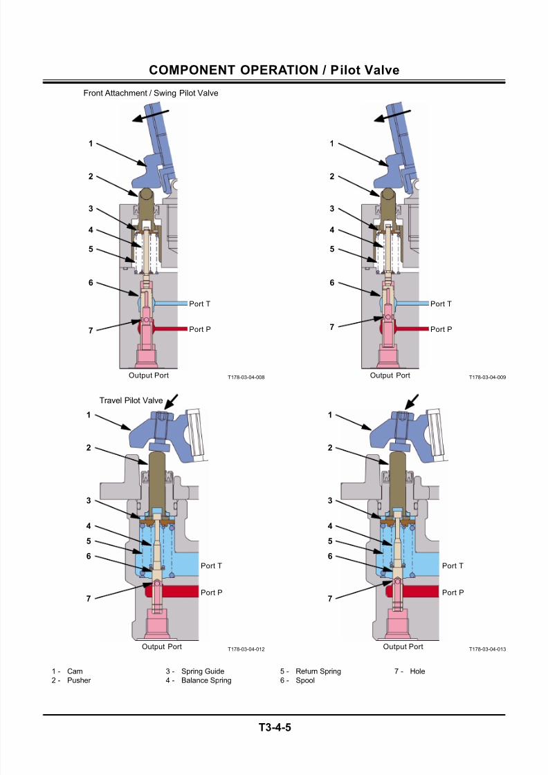
7/24/2019 t03 hitachi
http://slidepdf.com/reader/full/t03-hitachi 67/104
COMPONENT OPERATION / Pilot Valve
T3-4-5
T178-03-04-008
T178-03-04-012
T178-03-04-009
T178-03-04-013
1 - Cam 3 - Spring Guide 5 - Return Spring 7 - Hole
2 - Pusher 4 - Balance Spring 6 - Spool
Front Attachment / Swing Pilot Valve
1
2
3
4
6
5
7
Output Port
Port P
Port T
1
2
3
4
6
5
7
Output Port
Port P
Port T
Travel Pilot Valve
1
2
3
4
5
7
Output Port
Port P
Port T
6
1
2
3
4
5
7
Output Port
Port P
Port T
6
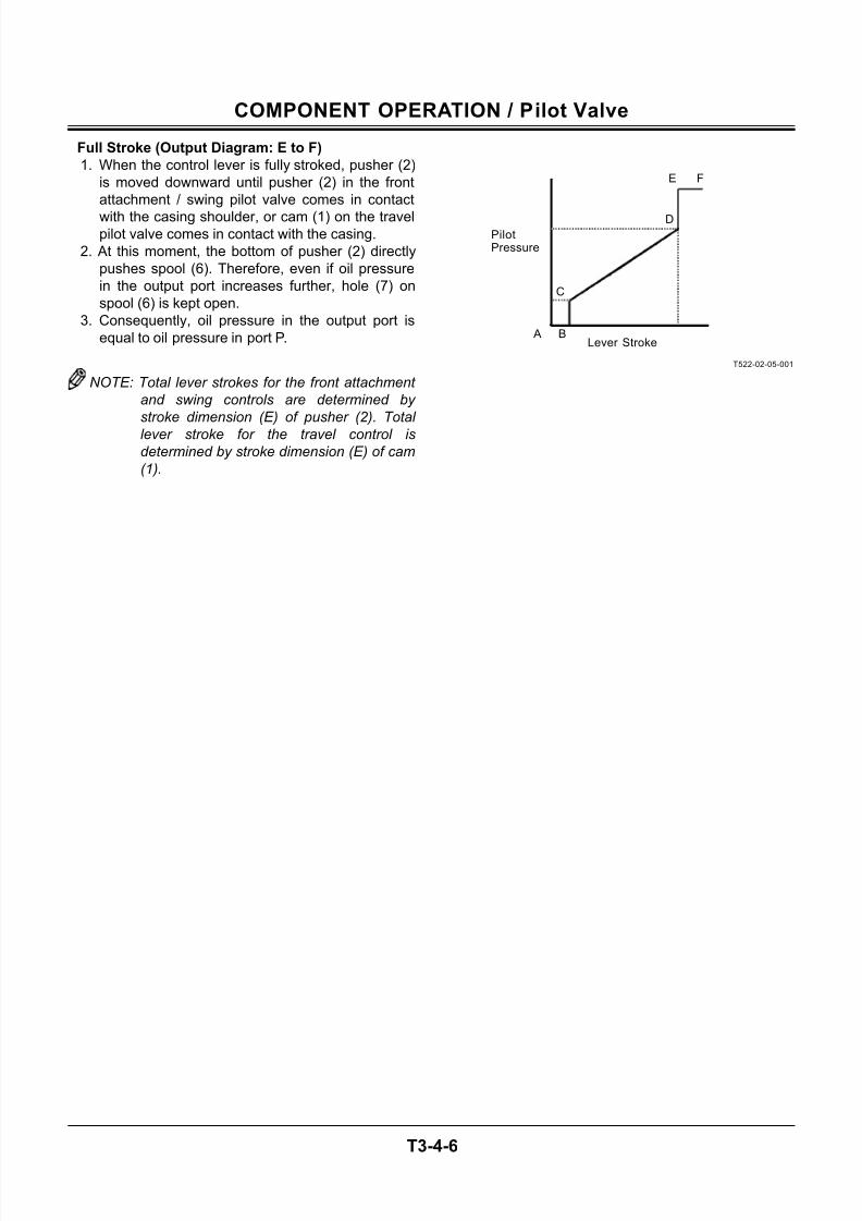
7/24/2019 t03 hitachi
http://slidepdf.com/reader/full/t03-hitachi 68/104
COMPONENT OPERATION / Pilot Valve
T3-4-6
Full Stroke (Output Diagram: E to F)
1. When the control lever is fully stroked, pusher (2)
is moved downward until pusher (2) in the front
attachment / swing pilot valve comes in contact
with the casing shoulder, or cam (1) on the travelpilot valve comes in contact with the casing.
2. At this moment, the bottom of pusher (2) directly
pushes spool (6). Therefore, even if oil pressure
in the output port increases further, hole (7) on
spool (6) is kept open.
3. Consequently, oil pressure in the output port is
equal to oil pressure in port P.
NOTE: Total lever strokes for the front attachment
and swing controls are determined by
stroke dimension (E) of pusher (2). Total
lever stroke for the travel control is
determined by stroke dimension (E) of cam
(1).
T522-02-05-001
PilotPressure
FE
D
C
B ALever Stroke
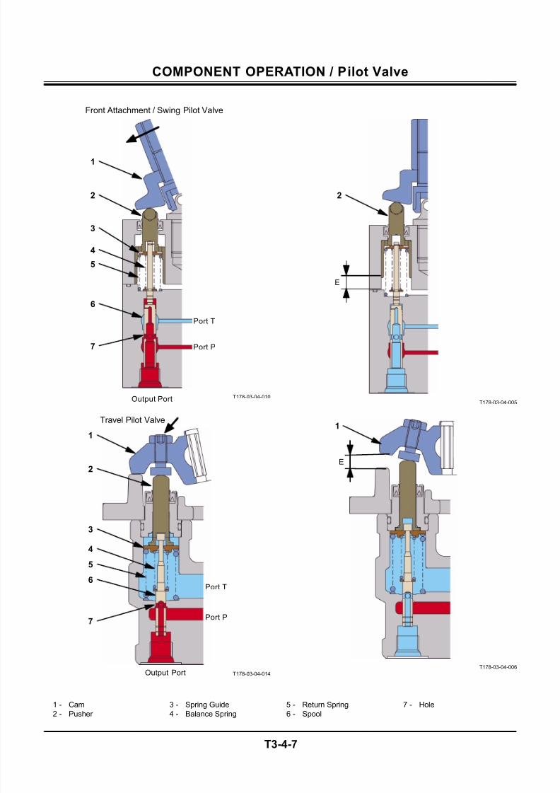
7/24/2019 t03 hitachi
http://slidepdf.com/reader/full/t03-hitachi 69/104
COMPONENT OPERATION / Pilot Valve
T3-4-7
T178-03-04-010
T178-03-04-014
T178-03-04-005
T178-03-04-006
1 - Cam 3 - Spring Guide 5 - Return Spring 7 - Hole
2 - Pusher 4 - Balance Spring 6 - Spool
Front Attachment / Swing Pilot Valve
1
2
3
4
6
5
7
Output Port
Port P
Port T
Travel Pilot Valve
1
2
3
4
5
7
Output Port
Port P
Port T6
2
E
E
1
7/24/2019 t03 hitachi
http://slidepdf.com/reader/full/t03-hitachi 70/104
COMPONENT OPERATION / Pilot Valve
T3-4-8
(Blank)
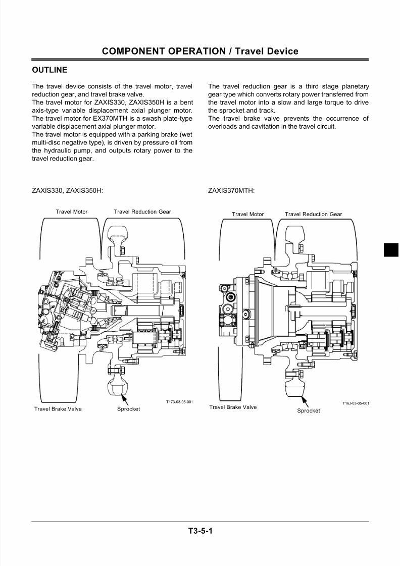
7/24/2019 t03 hitachi
http://slidepdf.com/reader/full/t03-hitachi 71/104
COMPONENT OPERATION / Travel Device
T3-5-1
OUTLINE
The travel device consists of the travel motor, travel
reduction gear, and travel brake valve.
The travel motor for ZAXIS330, ZAXIS350H is a bent
axis-type variable displacement axial plunger motor.
The travel motor for EX370MTH is a swash plate-type
variable displacement axial plunger motor.
The travel motor is equipped with a parking brake (wet
multi-disc negative type), is driven by pressure oil from
the hydraulic pump, and outputs rotary power to the
travel reduction gear.
ZAXIS330, ZAXIS350H:
T173-03-05-001
The travel reduction gear is a third stage planetary
gear type which converts rotary power transferred from
the travel motor into a slow and large torque to drive
the sprocket and track.
The travel brake valve prevents the occurrence of
overloads and cavitation in the travel circuit.
ZAXIS370MTH:
T16J-03-05-001
Travel Reduction Gear
SprocketTravel Brake Valve
Travel Motor Travel Reduction Gear
SprocketTravel Brake Valve
Travel Motor
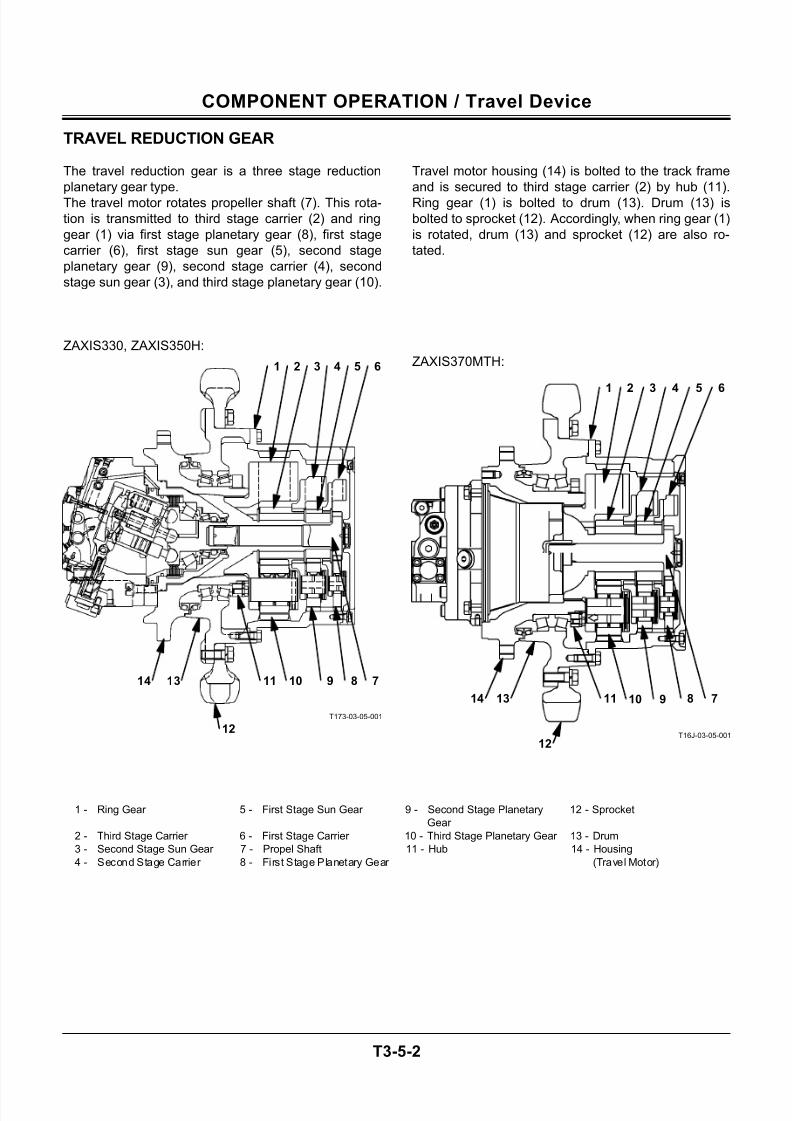
7/24/2019 t03 hitachi
http://slidepdf.com/reader/full/t03-hitachi 72/104
COMPONENT OPERATION / Travel Device
T3-5-2
TRAVEL REDUCTION GEAR
The travel reduction gear is a three stage reduction
planetary gear type.
The travel motor rotates propeller shaft (7). This rota-
tion is transmitted to third stage carrier (2) and ring
gear (1) via first stage planetary gear (8), first stage
carrier (6), first stage sun gear (5), second stage
planetary gear (9), second stage carrier (4), second
stage sun gear (3), and third stage planetary gear (10).
ZAXIS330, ZAXIS350H:
T173-03-05-001
Travel motor housing (14) is bolted to the track frame
and is secured to third stage carrier (2) by hub (11).
Ring gear (1) is bolted to drum (13). Drum (13) is
bolted to sprocket (12). Accordingly, when ring gear (1)
is rotated, drum (13) and sprocket (12) are also ro-
tated.
ZAXIS370MTH:
T16J-03-05-001
1 - Ring Gear 5 - First Stage Sun Gear 9 - Second Stage Planetary
Gear
12 - Sprocket
2 - Third Stage Carrier 6 - First Stage Carrier 10 - Third Stage Planetary Gear 13 - Drum
3 - Second Stage Sun Gear 7 - Propel Shaft 11 - Hub 14 - Housing
4 - Second Stage Carrier 8 - First Stage Planetary Gear (Travel Motor)
1 2 3 4 5 6
891011
12
14 13 7
1 2 3 4 5 6
891011 71314
12
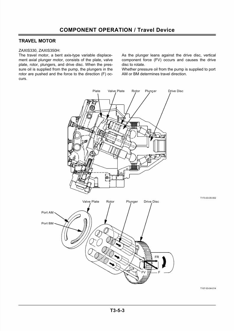
7/24/2019 t03 hitachi
http://slidepdf.com/reader/full/t03-hitachi 73/104
COMPONENT OPERATION / Travel Device
T3-5-3
TRAVEL MOTOR
ZAXIS330, ZAXIS350H:
The travel motor, a bent axis-type variable displace-
ment axial plunger motor, consists of the plate, valve
plate, rotor, plungers, and drive disc. When the pres-
sure oil is supplied from the pump, the plungers in the
rotor are pushed and the force to the direction (F) oc-
curs.
As the plunger leans against the drive disc, vertical
component force (FV) occurs and causes the drive
disc to rotate.
Whether pressure oil from the pump is supplied to port
AM or BM determines travel direction.
T173-03-05-002
T107-03-04-014
Rotor Plate Plunger Valve Plate Drive Disc
Rotor
Port BM
Port AM
Plunger Valve Plate Drive Disc
FR
FFV
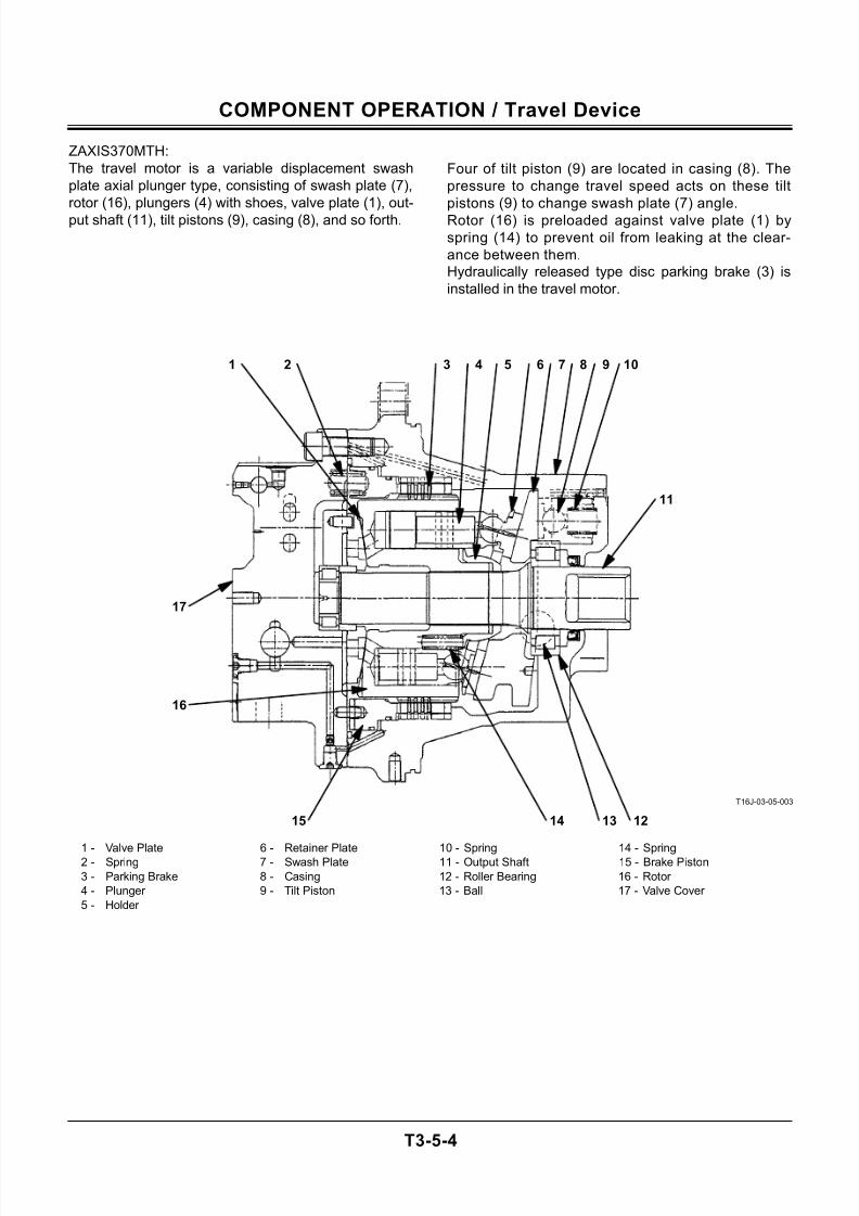
7/24/2019 t03 hitachi
http://slidepdf.com/reader/full/t03-hitachi 74/104
COMPONENT OPERATION / Travel Device
T3-5-4
ZAXIS370MTH:
The travel motor is a variable displacement swash
plate axial plunger type, consisting of swash plate (7),
rotor (16), plungers (4) with shoes, valve plate (1), out-
put shaft (11), tilt pistons (9), casing (8), and so forth.
Four of tilt piston (9) are located in casing (8). The
pressure to change travel speed acts on these tilt
pistons (9) to change swash plate (7) angle.
Rotor (16) is preloaded against valve plate (1) by
spring (14) to prevent oil from leaking at the clear-
ance between them.
Hydraulically released type disc parking brake (3) is
installed in the travel motor.
T16J-03-05-003
1 - Valve Plate 6 - Retainer Plate 10 - Spring 14 - Spring2 - Spring 7 - Swash Plate 11 - Output Shaft 15 - Brake Piston
3 - Parking Brake 8 - Casing 12 - Roller Bearing 16 - Rotor
4 - Plunger 9 - Tilt Piston 13 - Ball 17 - Valve Cover
5 - Holder
1 2 3 4 5 6 7 8 9 10
11
12131415
17
16
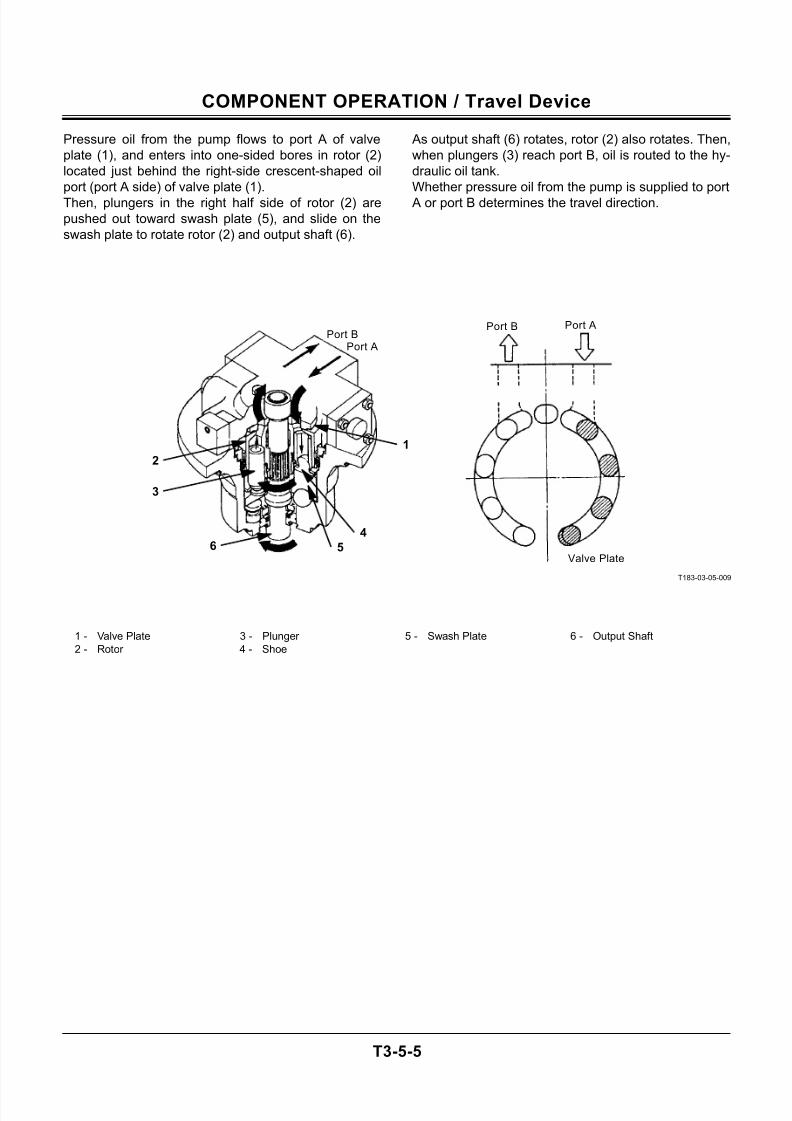
7/24/2019 t03 hitachi
http://slidepdf.com/reader/full/t03-hitachi 75/104
COMPONENT OPERATION / Travel Device
T3-5-5
Pressure oil from the pump flows to port A of valve
plate (1), and enters into one-sided bores in rotor (2)
located just behind the right-side crescent-shaped oil
port (port A side) of valve plate (1).
Then, plungers in the right half side of rotor (2) are
pushed out toward swash plate (5), and slide on the
swash plate to rotate rotor (2) and output shaft (6).
As output shaft (6) rotates, rotor (2) also rotates. Then,
when plungers (3) reach port B, oil is routed to the hy-
draulic oil tank.
Whether pressure oil from the pump is supplied to port
A or port B determines the travel direction.
T183-03-05-009
1 - Valve Plate 3 - Plunger 5 - Swash Plate 6 - Output Shaft
2 - Rotor 4 - Shoe
Port B
Valve Plate
Port APort B
Port A
1
2
3
64
5
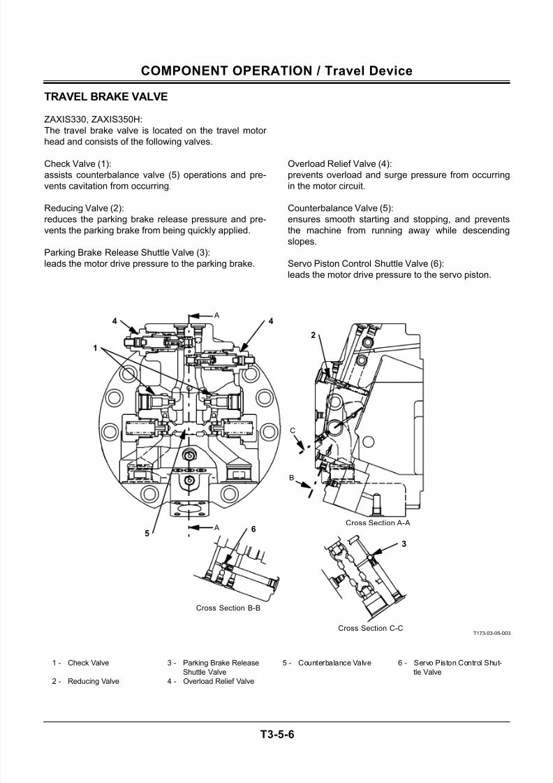
7/24/2019 t03 hitachi
http://slidepdf.com/reader/full/t03-hitachi 76/104
COMPONENT OPERATION / Travel Device
T3-5-6
TRAVEL BRAKE VALVE
ZAXIS330, ZAXIS350H:
The travel brake valve is located on the travel motor
head and consists of the following valves.
Check Valve (1):
assists counterbalance valve (5) operations and pre-
vents cavitation from occurring.
Reducing Valve (2):
reduces the parking brake release pressure and pre-
vents the parking brake from being quickly applied.
Parking Brake Release Shuttle Valve (3):
leads the motor drive pressure to the parking brake.
Overload Relief Valve (4):
prevents overload and surge pressure from occurring
in the motor circuit.
Counterbalance Valve (5):
ensures smooth starting and stopping, and prevents
the machine from running away while descending
slopes.
Servo Piston Control Shuttle Valve (6):
leads the motor drive pressure to the servo piston.
T173-03-05-003
1 - Check Valve 3 - Parking Brake Release
Shuttle Valve
5 - Counterbalance Valve 6 - Servo Piston Control Shut-
tle Valve
2 - Reducing Valve 4 - Overload Relief Valve
A
B
C
A
Cross Section B-B
Cross Section C-C
Cross Section A-A
1
44
2
5
3
6
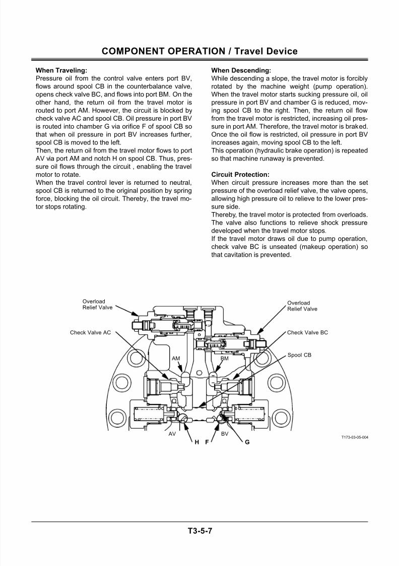
7/24/2019 t03 hitachi
http://slidepdf.com/reader/full/t03-hitachi 77/104
COMPONENT OPERATION / Travel Device
T3-5-7
When Traveling:
Pressure oil from the control valve enters port BV,
flows around spool CB in the counterbalance valve,
opens check valve BC, and flows into port BM. On the
other hand, the return oil from the travel motor is
routed to port AM. However, the circuit is blocked by
check valve AC and spool CB. Oil pressure in port BV
is routed into chamber G via orifice F of spool CB so
that when oil pressure in port BV increases further,
spool CB is moved to the left.
Then, the return oil from the travel motor flows to port
AV via port AM and notch H on spool CB. Thus, pres-
sure oil flows through the circuit , enabling the travel
motor to rotate.
When the travel control lever is returned to neutral,
spool CB is returned to the original position by spring
force, blocking the oil circuit. Thereby, the travel mo-tor stops rotating.
When Descending:
While descending a slope, the travel motor is forcibly
rotated by the machine weight (pump operation).
When the travel motor starts sucking pressure oil, oil
pressure in port BV and chamber G is reduced, mov-
ing spool CB to the right. Then, the return oil flow
from the travel motor is restricted, increasing oil pres-
sure in port AM. Therefore, the travel motor is braked.
Once the oil flow is restricted, oil pressure in port BV
increases again, moving spool CB to the left.
This operation (hydraulic brake operation) is repeated
so that machine runaway is prevented.
Circuit Protection:
When circuit pressure increases more than the set
pressure of the overload relief valve, the valve opens,
allowing high pressure oil to relieve to the lower pres-sure side.
Thereby, the travel motor is protected from overloads.
The valve also functions to relieve shock pressure
developed when the travel motor stops.
If the travel motor draws oil due to pump operation,
check valve BC is unseated (makeup operation) so
that cavitation is prevented.
T173-03-05-004BV AV
BM AM
FH G
Spool CB
Check Valve BCCheck Valve AC
OverloadRelief Valve
OverloadRelief Valve
7/24/2019 t03 hitachi
http://slidepdf.com/reader/full/t03-hitachi 78/104
COMPONENT OPERATION / Travel Device
T3-5-8
(Blank)
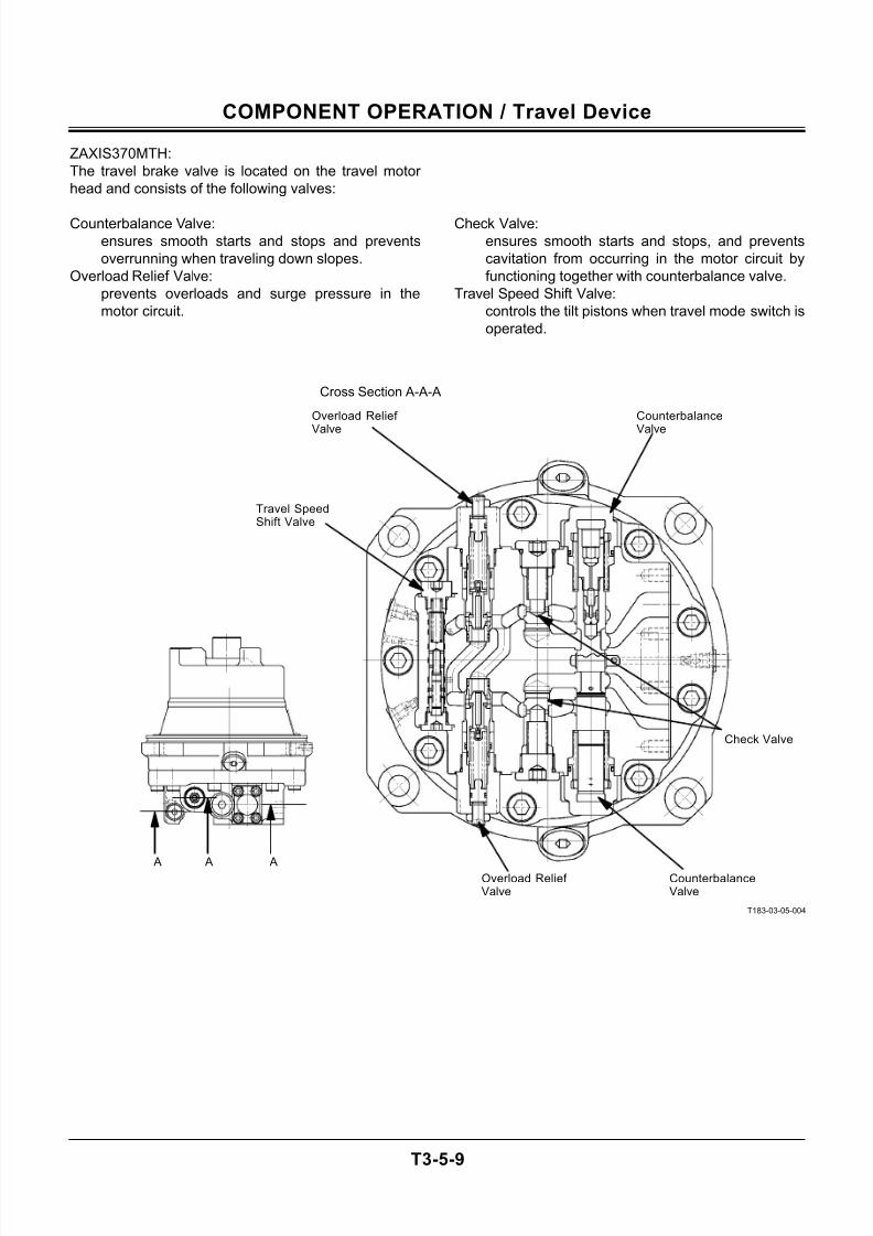
7/24/2019 t03 hitachi
http://slidepdf.com/reader/full/t03-hitachi 79/104
COMPONENT OPERATION / Travel Device
T3-5-9
ZAXIS370MTH:
The travel brake valve is located on the travel motor
head and consists of the following valves:
Counterbalance Valve:
ensures smooth starts and stops and prevents
overrunning when traveling down slopes.
Overload Relief Valve:
prevents overloads and surge pressure in the
motor circuit.
Check Valve:
ensures smooth starts and stops, and prevents
cavitation from occurring in the motor circuit by
functioning together with counterbalance valve.
Travel Speed Shift Valve:
controls the tilt pistons when travel mode switch is
operated.
T183-03-05-004
A A AOverload Relief Valve
CounterbalanceValve
Counterbalance
Valve
Overload Relief
Valve
Travel SpeedShift Valve
Check Valve
Cross Section A-A-A
7/24/2019 t03 hitachi
http://slidepdf.com/reader/full/t03-hitachi 80/104
COMPONENT OPERATION / Travel Device
T3-5-10
Travel Operation
When supply oil from the main control valve is routed
to port P1, supply oil flows around spool CB, opens
check valve BC and is led to motor port BM. However,
return oil from motor port AM is blocked by spool CB
in the counterbalance valve.
As supply oil pressure at port P1 increases, supply oil
is routed to chamber G through orifice F in spool CB,
moving spool CB down against spring force. Conse-
quently, return oil from motor port AM starts to flow
into port P2 through port AM and notch H in spool CB,
allowing the travel motor to rotate.
When the travel levers are returned to the neutral po-
sition, the oil in both ports P1 and P2 are routed to the
hydraulic oil tank through the control valve. Thus, oil
pressure in chamber G decrease, and spool CB ismoved back to the original position by spring force.
Then, the oil flow circuits is blocked, causing the
travel motors to stop rotating.
Descending Operation
When the machine travels down a slope, the travel
motors are forcibly driven by the machine weight so
that the motor draws oil like a pump. When the motor
draws oil, oil pressure at port P1 and chamber G de-
crease, causing spool CB to move upwards to restrict
return circuit from the motor.
Then, the return oil flow from the motor is restrictedby the spool, increasing pressure at port AM.
The increased pressure at port AM brakes the motor.
Thus, the restricted return oil flow from the travel mo-
tor increases the pressure at port P1 again, moving
spool CB back down. This repeated movement of the
spool (hydraulic brake action) prevents the machine
from overrunning.
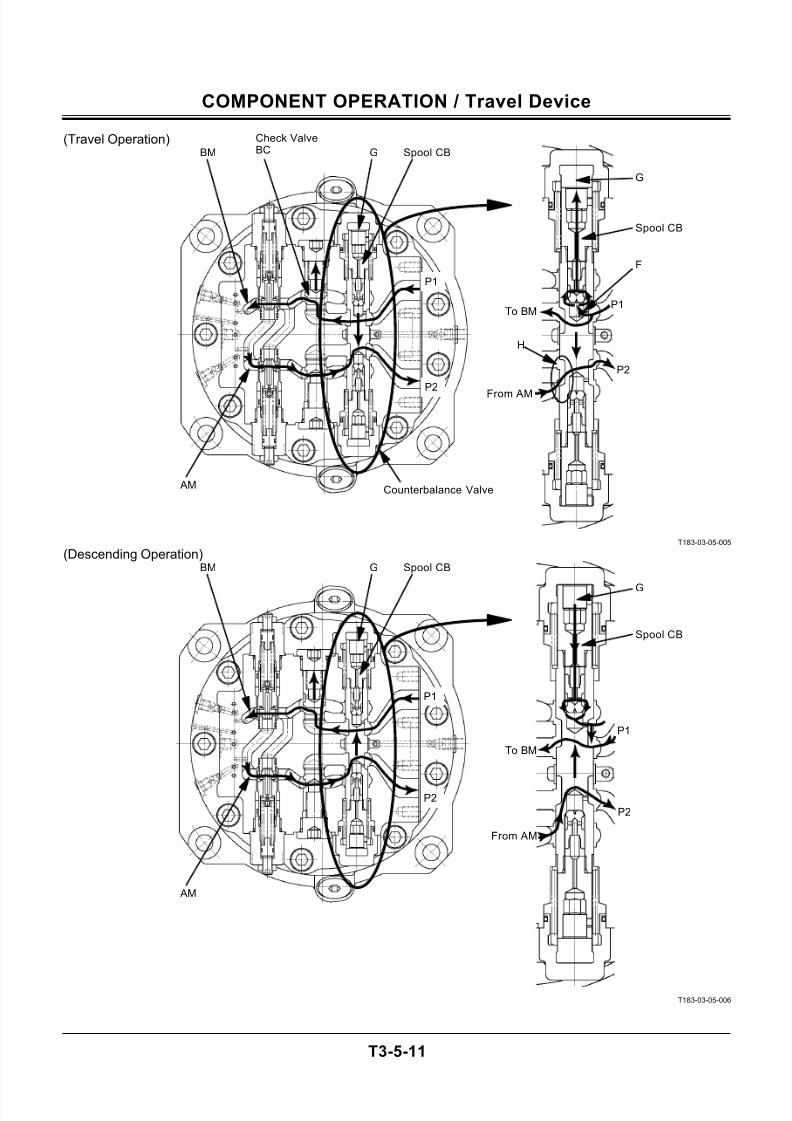
7/24/2019 t03 hitachi
http://slidepdf.com/reader/full/t03-hitachi 81/104
COMPONENT OPERATION / Travel Device
T3-5-11
(Travel Operation)
T183-03-05-005
(Descending Operation)
T183-03-05-006
Check ValveBC G Spool CB
P2
P1
Counterbalance Valve AM
BM
Spool CB
From AM
P2
H
To BMP1
F
G
G Spool CB
P2
P1
AM
BM
Spool CB
From AM
P2
To BM
P1
G
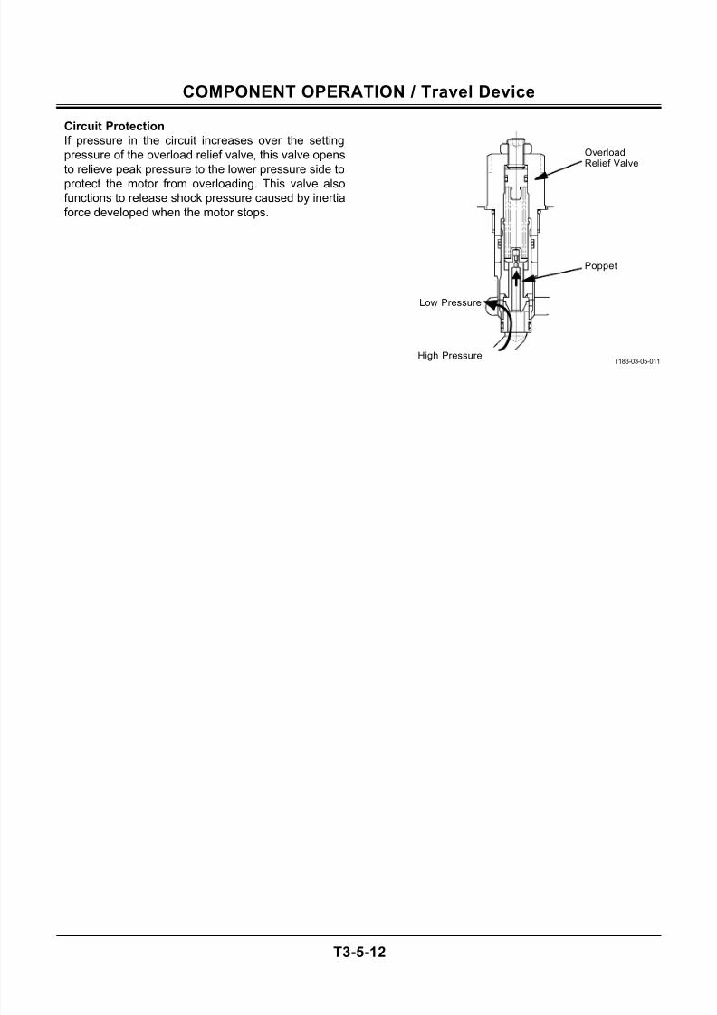
7/24/2019 t03 hitachi
http://slidepdf.com/reader/full/t03-hitachi 82/104
COMPONENT OPERATION / Travel Device
T3-5-12
Circuit Protection
If pressure in the circuit increases over the setting
pressure of the overload relief valve, this valve opens
to relieve peak pressure to the lower pressure side to
protect the motor from overloading. This valve also
functions to release shock pressure caused by inertia
force developed when the motor stops.
T183-03-05-011
Low Pressure
High Pressure
Poppet
OverloadRelief Valve

7/24/2019 t03 hitachi
http://slidepdf.com/reader/full/t03-hitachi 83/104
COMPONENT OPERATION / Travel Device
T3-5-13
(Blank)
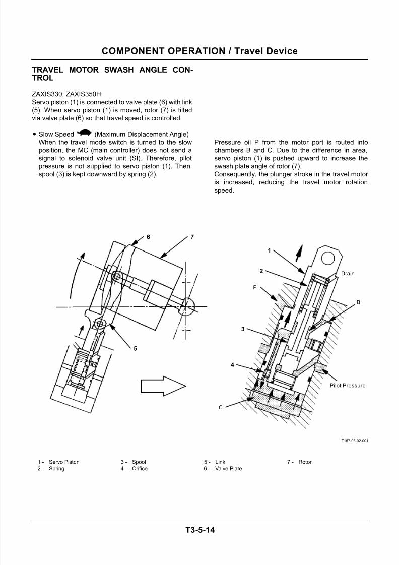
7/24/2019 t03 hitachi
http://slidepdf.com/reader/full/t03-hitachi 84/104
COMPONENT OPERATION / Travel Device
T3-5-14
TRAVEL MOTOR SWASH ANGLE CON-TROL
ZAXIS330, ZAXIS350H:
Servo piston (1) is connected to valve plate (6) with link
(5). When servo piston (1) is moved, rotor (7) is tilted
via valve plate (6) so that travel speed is controlled.
• Slow Speed (Maximum Displacement Angle)
When the travel mode switch is turned to the slow
position, the MC (main controller) does not send a
signal to solenoid valve unit (SI). Therefore, pilot
pressure is not supplied to servo piston (1). Then,
spool (3) is kept downward by spring (2).
Pressure oil P from the motor port is routed into
chambers B and C. Due to the difference in area,
servo piston (1) is pushed upward to increase the
swash plate angle of rotor (7).
Consequently, the plunger stroke in the travel motor
is increased, reducing the travel motor rotation
speed.
T157-03-02-001
1 - Servo Piston 3 - Spool 5 - Link 7 - Rotor
2 - Spring 4 - Orifice 6 - Valve Plate
2
1
5
6 7
3
4
B
C
P
Drain
Pilot Pressure
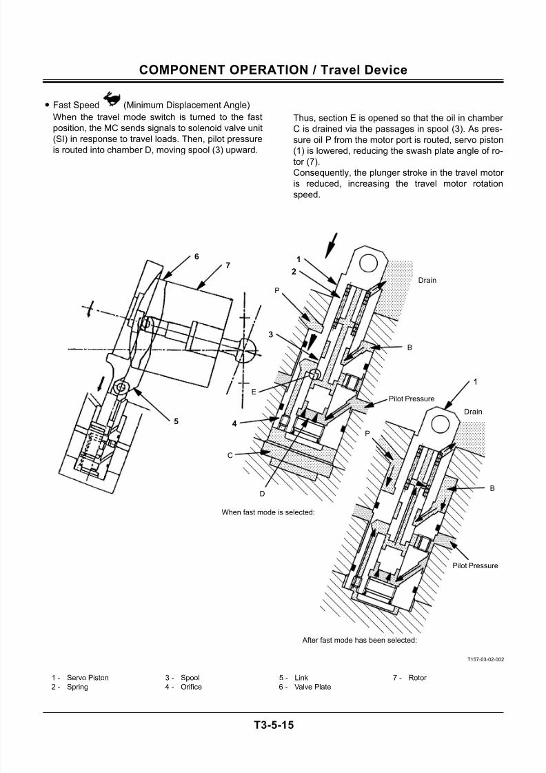
7/24/2019 t03 hitachi
http://slidepdf.com/reader/full/t03-hitachi 85/104
COMPONENT OPERATION / Travel Device
T3-5-15
• Fast Speed (Minimum Displacement Angle)
When the travel mode switch is turned to the fast
position, the MC sends signals to solenoid valve unit
(SI) in response to travel loads. Then, pilot pressure
is routed into chamber D, moving spool (3) upward.
Thus, section E is opened so that the oil in chamber
C is drained via the passages in spool (3). As pres-
sure oil P from the motor port is routed, servo piston
(1) is lowered, reducing the swash plate angle of ro-
tor (7).
Consequently, the plunger stroke in the travel motor
is reduced, increasing the travel motor rotation
speed.
T157-03-02-002
1 - Servo Piston 3 - Spool 5 - Link 7 - Rotor 2 - Spring 4 - Orifice 6 - Valve Plate
3
67
5
1
2
4
B
D
C
E
P
P
Drain
Drain
After fast mode has been selected:
When fast mode is selected:
Pilot Pressure
Pilot Pressure
1
B
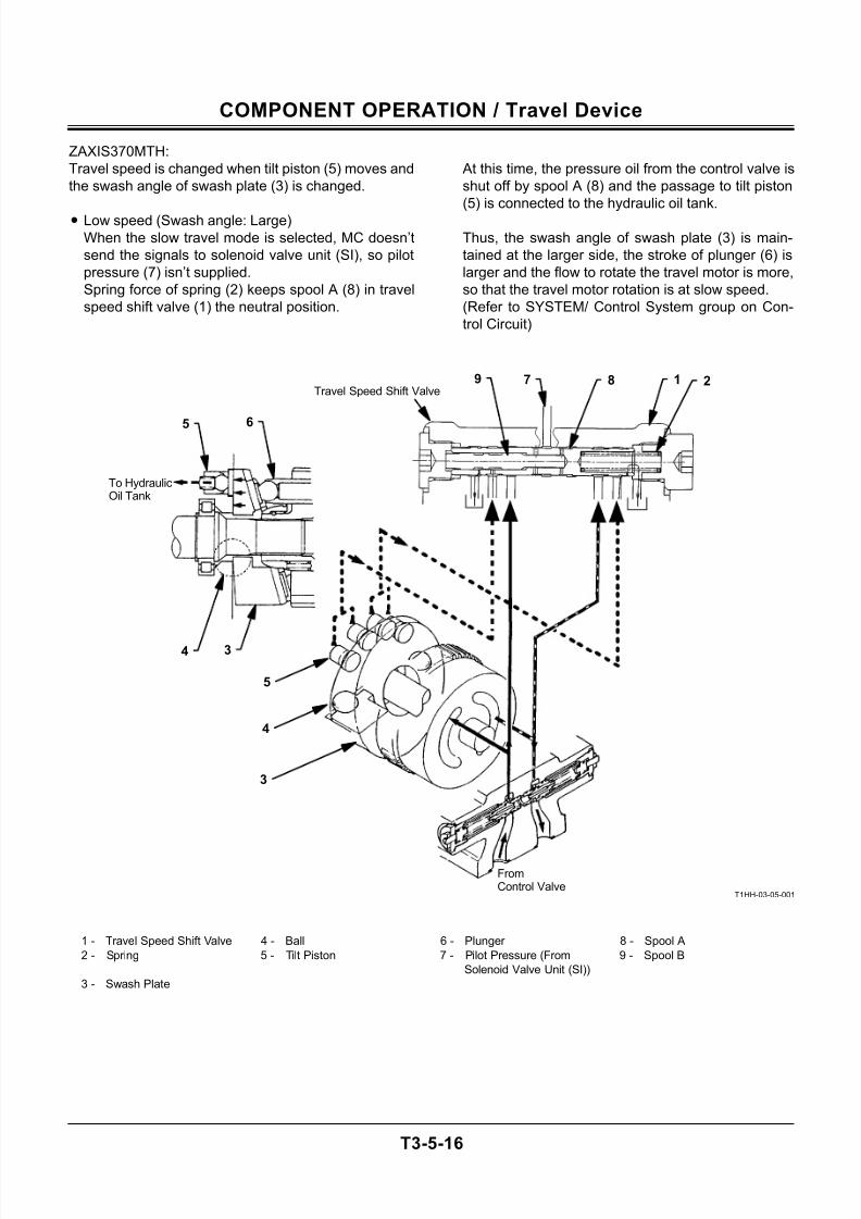
7/24/2019 t03 hitachi
http://slidepdf.com/reader/full/t03-hitachi 86/104
COMPONENT OPERATION / Travel Device
T3-5-16
ZAXIS370MTH:
Travel speed is changed when tilt piston (5) moves and
the swash angle of swash plate (3) is changed.
• Low speed (Swash angle: Large)
When the slow travel mode is selected, MC doesn’t
send the signals to solenoid valve unit (SI), so pilot
pressure (7) isn’t supplied.
Spring force of spring (2) keeps spool A (8) in travel
speed shift valve (1) the neutral position.
At this time, the pressure oil from the control valve is
shut off by spool A (8) and the passage to tilt piston
(5) is connected to the hydraulic oil tank.
Thus, the swash angle of swash plate (3) is main-
tained at the larger side, the stroke of plunger (6) is
larger and the flow to rotate the travel motor is more,
so that the travel motor rotation is at slow speed.
(Refer to SYSTEM/ Control System group on Con-
trol Circuit)
T1HH-03-05-001
1 - Travel Speed Shift Valve 4 - Ball 6 - Plunger 8 - Spool A
2 - Spring 5 - Tilt Piston 7 - Pilot Pressure (From
Solenoid Valve Unit (SI))
9 - Spool B
3 - Swash Plate
FromControl Valve
Travel Speed Shift Valve
To HydraulicOil Tank
5 6
4 3
5
4
3
7 8 1 29
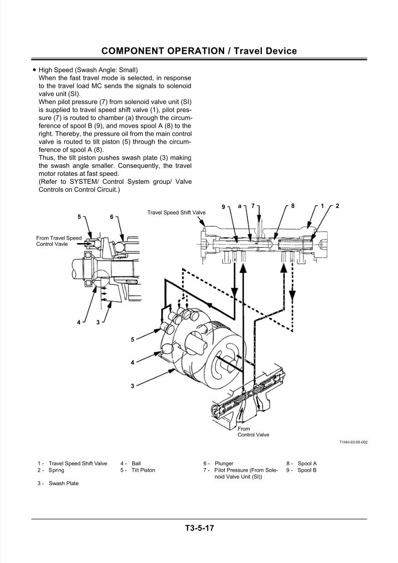
7/24/2019 t03 hitachi
http://slidepdf.com/reader/full/t03-hitachi 87/104
COMPONENT OPERATION / Travel Device
T3-5-17
• High Speed (Swash Angle: Small)
When the fast travel mode is selected, in response
to the travel load MC sends the signals to solenoid
valve unit (SI).
When pilot pressure (7) from solenoid valve unit (SI)
is supplied to travel speed shift valve (1), pilot pres-
sure (7) is routed to chamber (a) through the circum-
ference of spool B (9), and moves spool A (8) to the
right. Thereby, the pressure oil from the main control
valve is routed to tilt piston (5) through the circum-
ference of spool A (8).
Thus, the tilt piston pushes swash plate (3) making
the swash angle smaller. Consequently, the travel
motor rotates at fast speed.
(Refer to SYSTEM/ Control System group/ Valve
Controls on Control Circuit.)
T1HH-03-05-002
1 - Travel Speed Shift Valve 4 - Ball 6 - Plunger 8 - Spool A
2 - Spring 5 - Tilt Piston 7 - Pilot Pressure (From Sole-
noid Valve Unit (SI))
9 - Spool B
3 - Swash Plate
FromControl Valve
From Travel SpeedControl Vavle
5 6
4 3
5
4
3
7 8 1 2aTravel Speed Shift Valve
9

7/24/2019 t03 hitachi
http://slidepdf.com/reader/full/t03-hitachi 88/104
COMPONENT OPERATION / Travel Device
T3-5-18
(Blank)
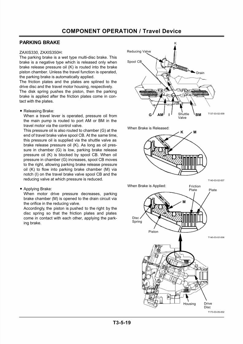
7/24/2019 t03 hitachi
http://slidepdf.com/reader/full/t03-hitachi 89/104
COMPONENT OPERATION / Travel Device
T3-5-19
PARKING BRAKE
ZAXIS330, ZAXIS350H:
The parking brake is a wet type multi-disc brake. This
brake is a negative type which is released only when
brake release pressure oil (K) is routed into the brake
piston chamber. Unless the travel function is operated,
the parking brake is automatically applied.
The friction plates and the plates are splined to the
drive disc and the travel motor housing, respectively.
The disk spring pushes the piston, then the parking
brake is applied after the friction plates come in con-
tact with the plates.
• Releasing Brake:
When a travel lever is operated, pressure oil from
the main pump is routed to port AM or BM in thetravel motor via the control valve.
This pressure oil is also routed to chamber (G) at the
end of travel brake valve spool CB. At the same time,
this pressure oil is supplied via the shuttle valve as
brake release pressure oil (K). As long as oil pres-
sure in chamber (G) is low, parking brake release
pressure oil (K) is blocked by spool CB. When oil
pressure in chamber (G) increases, spool CB moves
to the right, allowing parking brake release pressure
oil (K) to flow into parking brake chamber (M) via
notch (I) on the travel brake valve spool CB and the
reducing valve at which pressure is reduced.
• Applying Brake:
When motor drive pressure decreases, parking
brake chamber (M) is opened to the drain circuit via
the orifice in the reducing valve.
Accordingly, the piston is pushed to the right by the
disc spring so that the friction plates and plates
come in contact with each other, applying the park-
ing brake.
T137-03-02-009
T140-03-02-007
T140-03-02-006
T173-03-05-002
When Brake is Applied:
When Brake is Released:K M
M
K
G AM I BMShuttleValve
Drain
Housing DriveDisc
Spool CB
Reducing Valve
DiscSpring
Piston
FrictionPlate Plate
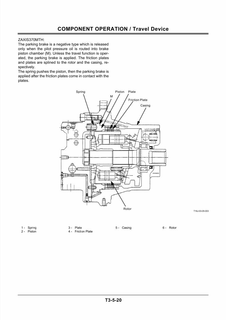
7/24/2019 t03 hitachi
http://slidepdf.com/reader/full/t03-hitachi 90/104
COMPONENT OPERATION / Travel Device
T3-5-20
ZAXIS370MTH:
The parking brake is a negative type which is released
only when the pilot pressure oil is routed into brake
piston chamber (M). Unless the travel function is oper-
ated, the parking brake is applied. The friction plates
and plates are splined to the rotor and the casing, re-
spectively.
The spring pushes the piston, then the parking brake is
applied after the friction plates come in contact with the
plates.
T16J-03-05-003
1 - Spring 3 - Plate 5 - Casing 6 - Rotor
2 - Piston 4 - Friction Plate
Casing
Friction Plate
Rotor
Plate
M
PistonSpring
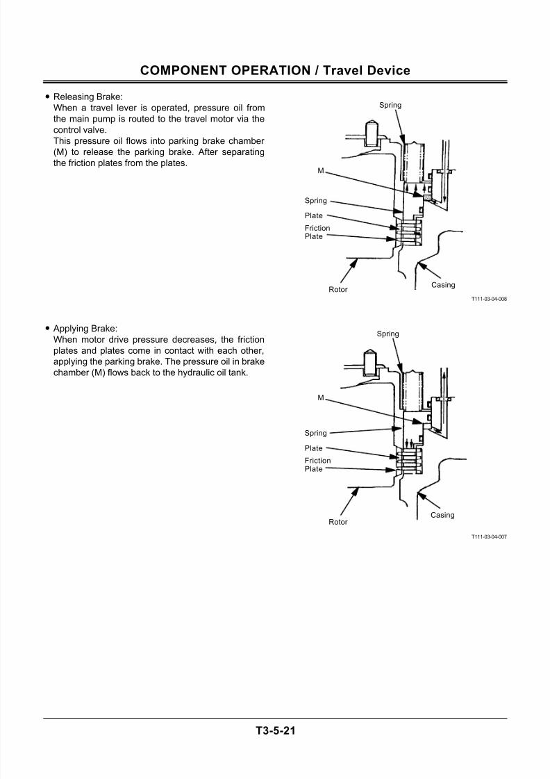
7/24/2019 t03 hitachi
http://slidepdf.com/reader/full/t03-hitachi 91/104
COMPONENT OPERATION / Travel Device
T3-5-21
• Releasing Brake:
When a travel lever is operated, pressure oil from
the main pump is routed to the travel motor via the
control valve.
This pressure oil flows into parking brake chamber
(M) to release the parking brake. After separating
the friction plates from the plates.
• Applying Brake:
When motor drive pressure decreases, the friction
plates and plates come in contact with each other,
applying the parking brake. The pressure oil in brake
chamber (M) flows back to the hydraulic oil tank.
T111-03-04-008
T111-03-04-007
M
FrictionPlate
CasingRotor
Plate
Spring
Spring
FrictionPlate
CasingRotor
Plate
Spring
Spring
M
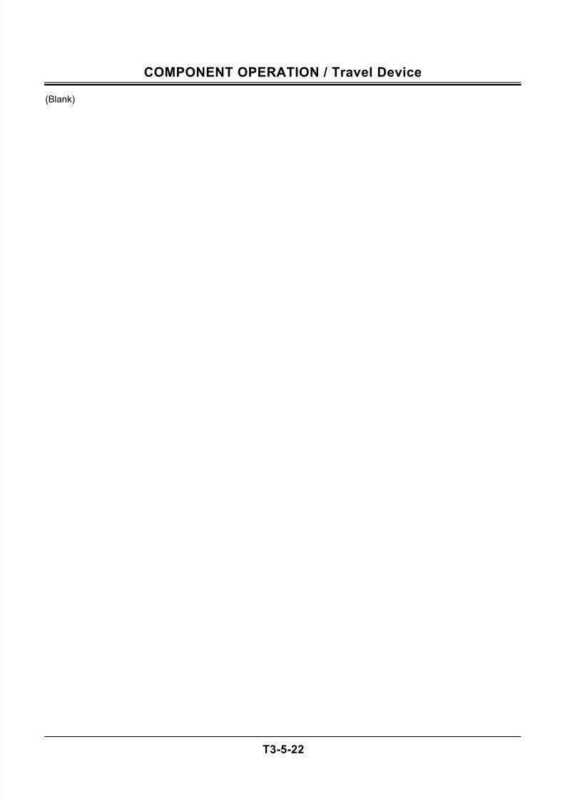
7/24/2019 t03 hitachi
http://slidepdf.com/reader/full/t03-hitachi 92/104
COMPONENT OPERATION / Travel Device
T3-5-22
(Blank)
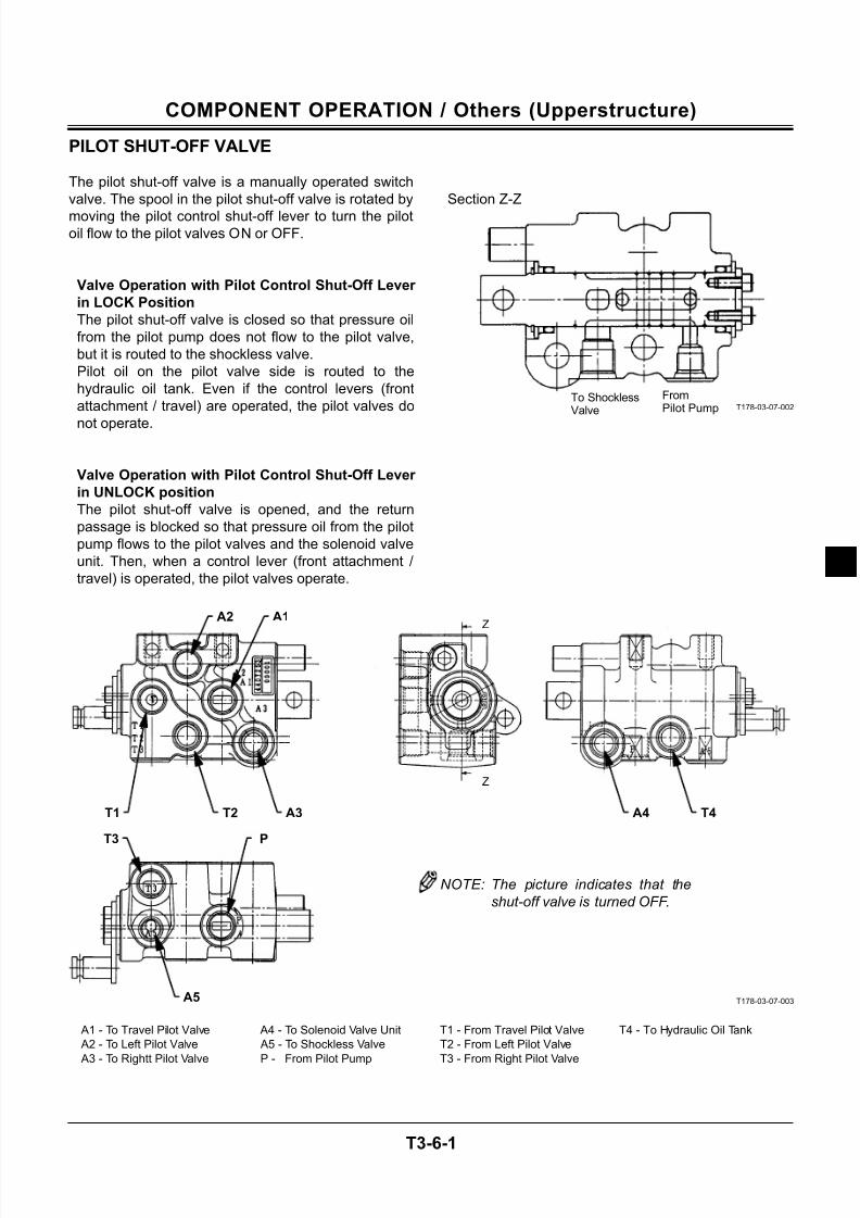
7/24/2019 t03 hitachi
http://slidepdf.com/reader/full/t03-hitachi 93/104
COMPONENT OPERATION / Others (Upperstructure)
T3-6-1
PILOT SHUT-OFF VALVE
The pilot shut-off valve is a manually operated switch
valve. The spool in the pilot shut-off valve is rotated by
moving the pilot control shut-off lever to turn the pilotoil flow to the pilot valves ON or OFF.
Valve Operation with Pilot Control Shut-Off Lever
in LOCK Position
The pilot shut-off valve is closed so that pressure oil
from the pilot pump does not flow to the pilot valve,
but it is routed to the shockless valve.
Pilot oil on the pilot valve side is routed to the
hydraulic oil tank. Even if the control levers (front
attachment / travel) are operated, the pilot valves do
not operate.
Valve Operation with Pilot Control Shut-Off Lever
in UNLOCK position
The pilot shut-off valve is opened, and the return
passage is blocked so that pressure oil from the pilot
pump flows to the pilot valves and the solenoid valve
unit. Then, when a control lever (front attachment /
travel) is operated, the pilot valves operate.
Section Z-Z
T178-03-07-002
T178-03-07-003
A1 - To Travel Pilot Valve A4 - To Solenoid Valve Unit T1 - From Travel Pilot Valve T4 - To Hydraulic Oil Tank
A2 - To Left Pilot Valve A5 - To Shockless Valve T2 - From Left Pilot Valve
A3 - To Rightt Pilot Valve P - From Pilot Pump T3 - From Right Pilot Valve
To ShocklessValve
FromPilot Pump
T4A4
Z
Z
A3T2T1
A1A2
T3 P
A5
NOTE: The picture indicates that the
shut-off valve is turned OFF.
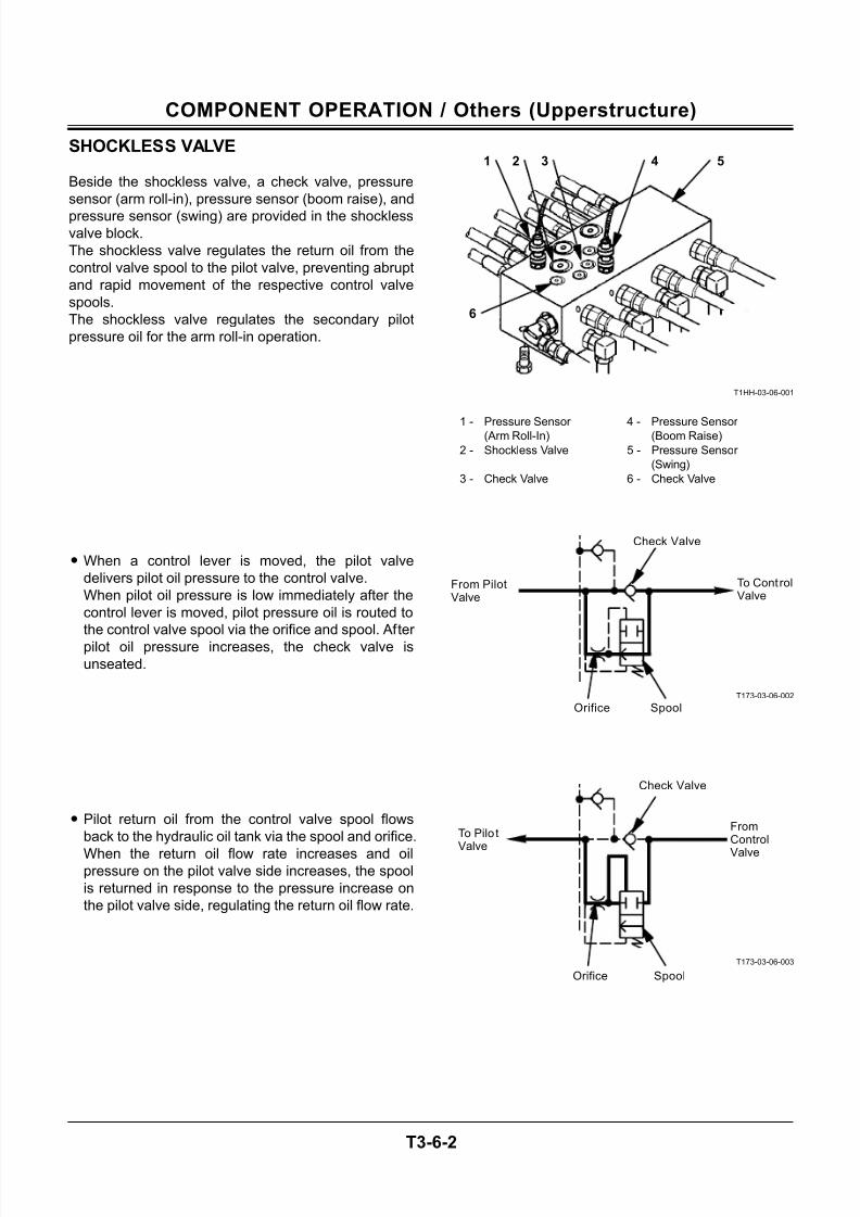
7/24/2019 t03 hitachi
http://slidepdf.com/reader/full/t03-hitachi 94/104
COMPONENT OPERATION / Others (Upperstructure)
T3-6-2
SHOCKLESS VALVE
Beside the shockless valve, a check valve, pressure
sensor (arm roll-in), pressure sensor (boom raise), and
pressure sensor (swing) are provided in the shocklessvalve block.
The shockless valve regulates the return oil from the
control valve spool to the pilot valve, preventing abrupt
and rapid movement of the respective control valve
spools.
The shockless valve regulates the secondary pilot
pressure oil for the arm roll-in operation.
• When a control lever is moved, the pilot valve
delivers pilot oil pressure to the control valve.
When pilot oil pressure is low immediately after the
control lever is moved, pilot pressure oil is routed to
the control valve spool via the orifice and spool. After
pilot oil pressure increases, the check valve is
unseated.
• Pilot return oil from the control valve spool flows
back to the hydraulic oil tank via the spool and orifice.
When the return oil flow rate increases and oilpressure on the pilot valve side increases, the spool
is returned in response to the pressure increase on
the pilot valve side, regulating the return oil flow rate.
T1HH-03-06-001
1 - Pressure Sensor (Arm Roll-In) 4 - Pressure Sensor (Boom Raise)
2 - Shockless Valve 5 - Pressure Sensor
(Swing)
3 - Check Valve 6 - Check Valve
T173-03-06-002
T173-03-06-003
1 2 3 4 5
6
To ControlValve
From PilotValve
SpoolOrifice
Check Valve
FromControl
Valve
To Pilo tValve
SpoolOrifice
Check Valve
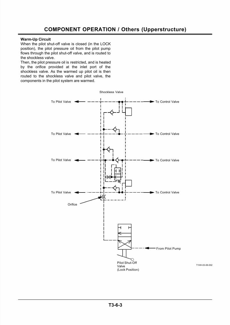
7/24/2019 t03 hitachi
http://slidepdf.com/reader/full/t03-hitachi 95/104
COMPONENT OPERATION / Others (Upperstructure)
T3-6-3
Warm-Up Circuit
When the pilot shut-off valve is closed (in the LOCK
position), the pilot pressure oil from the pilot pump
flows through the pilot shut-off valve, and is routed to
the shockless valve.Then, the pilot pressure oil is restricted, and is heated
by the orifice provided at the inlet port of the
shockless valve. As the warmed up pilot oil is then
routed to the shockless valve and pilot valve, the
components in the pilot system are warmed.
T1HH-03-06-002
To Pilot Valve
To Pilot Valve
To Pilot Valve
To Pilot Valve
From Pilot Pump
Pilot Shut-Off Valve(Lock Position)
Orifice
To Control Valve
To Control Valve
To Control Valve
To Control Valve
Shockless Valve
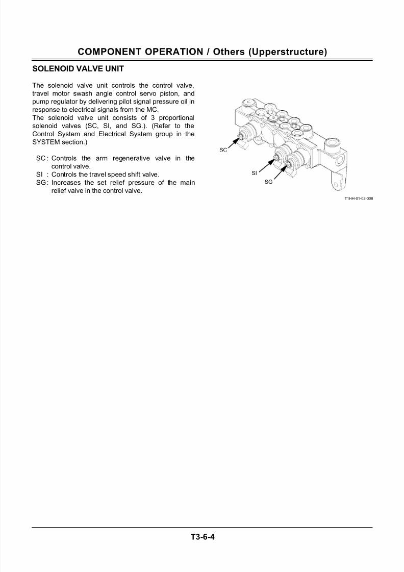
7/24/2019 t03 hitachi
http://slidepdf.com/reader/full/t03-hitachi 96/104
COMPONENT OPERATION / Others (Upperstructure)
T3-6-4
SOLENOID VALVE UNIT
The solenoid valve unit controls the control valve,
travel motor swash angle control servo piston, and
pump regulator by delivering pilot signal pressure oil inresponse to electrical signals from the MC.
The solenoid valve unit consists of 3 proportional
solenoid valves (SC, SI, and SG.). (Refer to the
Control System and Electrical System group in the
SYSTEM section.)
SC : Controls the arm regenerative valve in the
control valve.
SI : Controls the travel speed shift valve.
SG: Increases the set relief pressure of the main
relief valve in the control valve.
T1HH-01-02-008
SG
SI
SC
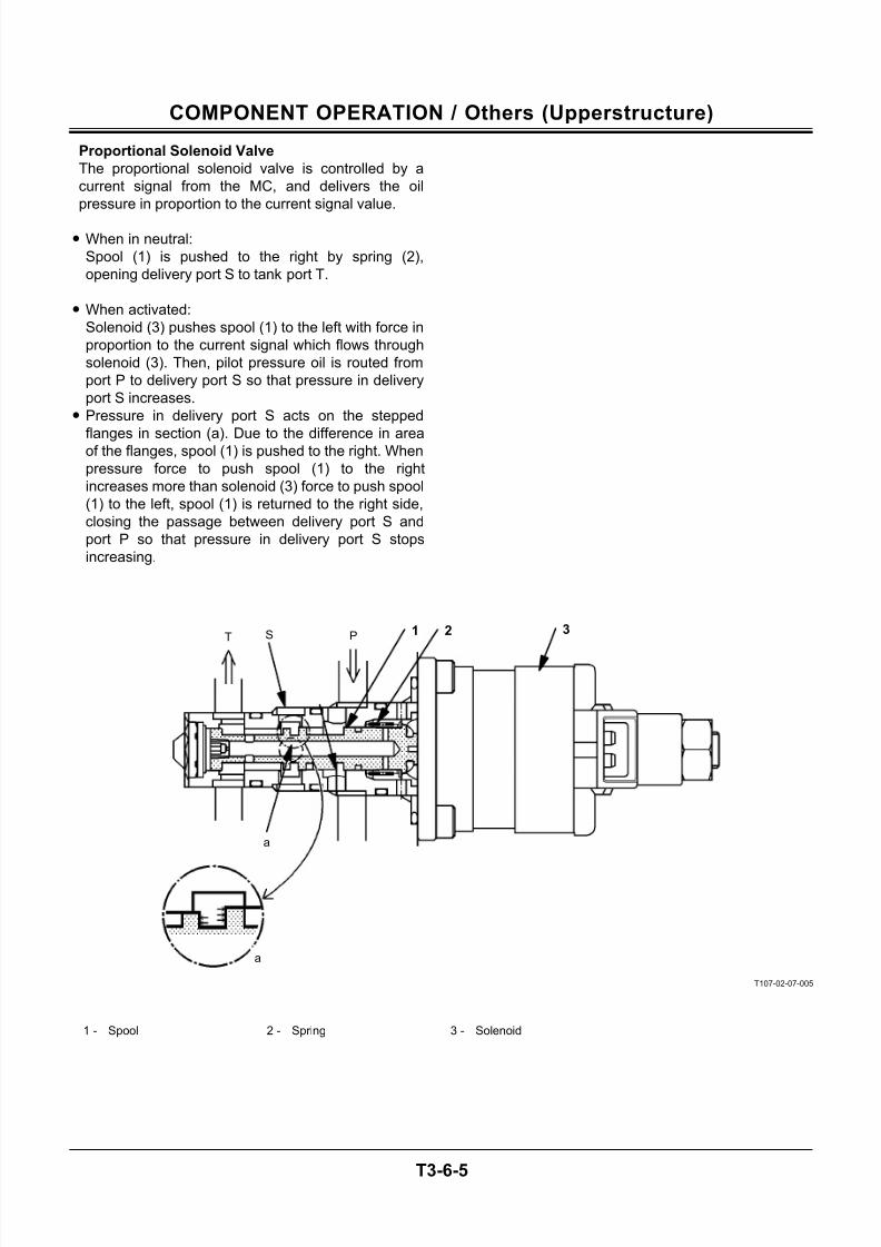
7/24/2019 t03 hitachi
http://slidepdf.com/reader/full/t03-hitachi 97/104
COMPONENT OPERATION / Others (Upperstructure)
T3-6-5
Proportional Solenoid Valve
The proportional solenoid valve is controlled by a
current signal from the MC, and delivers the oil
pressure in proportion to the current signal value.
• When in neutral:
Spool (1) is pushed to the right by spring (2),
opening delivery port S to tank port T.
• When activated:
Solenoid (3) pushes spool (1) to the left with force in
proportion to the current signal which flows through
solenoid (3). Then, pilot pressure oil is routed from
port P to delivery port S so that pressure in delivery
port S increases.
• Pressure in delivery port S acts on the stepped
flanges in section (a). Due to the difference in areaof the flanges, spool (1) is pushed to the right. When
pressure force to push spool (1) to the right
increases more than solenoid (3) force to push spool
(1) to the left, spool (1) is returned to the right side,
closing the passage between delivery port S and
port P so that pressure in delivery port S stops
increasing.
T107-02-07-005
1 - Spool 2 - Spring 3 - Solenoid
a
a
S PT1 2 3
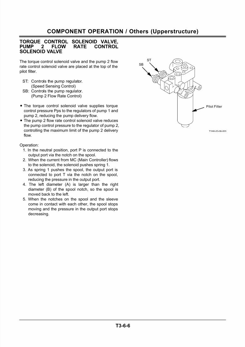
7/24/2019 t03 hitachi
http://slidepdf.com/reader/full/t03-hitachi 98/104
COMPONENT OPERATION / Others (Upperstructure)
T3-6-6
TORQUE CONTROL SOLENOID VALVE,PUMP 2 FLOW RATE CONTROLSOLENOID VALVE
The torque control solenoid valve and the pump 2 flowrate control solenoid valve are placed at the top of the
pilot filter.
ST: Controls the pump regulator.
(Speed Sensing Control)
SB: Controls the pump regulator.
(Pump 2 Flow Rate Control)
• The torque control solenoid valve supplies torque
control pressure Pps to the regulators of pump 1 and
pump 2, reducing the pump delivery flow.
•The pump 2 flow rate control solenoid valve reducesthe pump control pressure to the regulator of pump 2,
controlling the maximum limit of the pump 2 delivery
flow.
Operation:
1. In the neutral position, port P is connected to the
output port via the notch on the spool.
2. When the current from MC (Main Controller) flows
to the solenoid, the solenoid pushes spring 1.
3. As spring 1 pushes the spool, the output port is
connected to port T via the notch on the spool,
reducing the pressure in the output port.
4. The left diameter (A) is larger than the right
diameter (B) of the spool notch, so the spool is
moved back to the left.
5. When the notches on the spool and the sleeve
come in contact with each other, the spool stops
moving and the pressure in the output port stops
decreasing.
T1HH-03-06-003
ST
Pilot Filter
SB
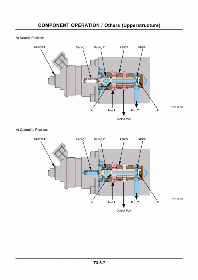
7/24/2019 t03 hitachi
http://slidepdf.com/reader/full/t03-hitachi 99/104
COMPONENT OPERATION / Others (Upperstructure)
T3-6-7
At Neutral Position:
T176-03-01-030
At Operating Position:
T176-03-01-031
Spring 1
Spring 1
Solenoid
Solenoid
Spring 2
Spring 2
A
A
Port P
Port P
Sleeve
Sleeve
Spool
Spool
Output Port
Output Port
Port T
Port T
B
B
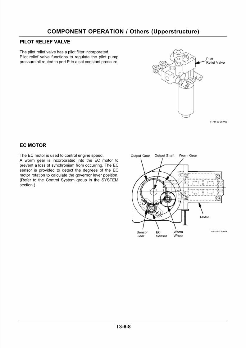
7/24/2019 t03 hitachi
http://slidepdf.com/reader/full/t03-hitachi 100/104
COMPONENT OPERATION / Others (Upperstructure)
T3-6-8
PILOT RELIEF VALVE
The pilot relief valve has a pilot filter incorporated.
Pilot relief valve functions to regulate the pilot pump
pressure oil routed to port P to a set constant pressure.
EC MOTOR
The EC motor is used to control engine speed.
A worm gear is incorporated into the EC motor to
prevent a loss of synchronism from occurring. The EC
sensor is provided to detect the degrees of the EC
motor rotation to calculate the governor lever position.
(Refer to the Control System group in the SYSTEM
section.)
T1HH-03-06-003
T157-02-05-018
PilotRelief Valve
Output Shaft
Sensor Gear
ECSensor
WormWheel
Motor
Worm Gear Output Gear
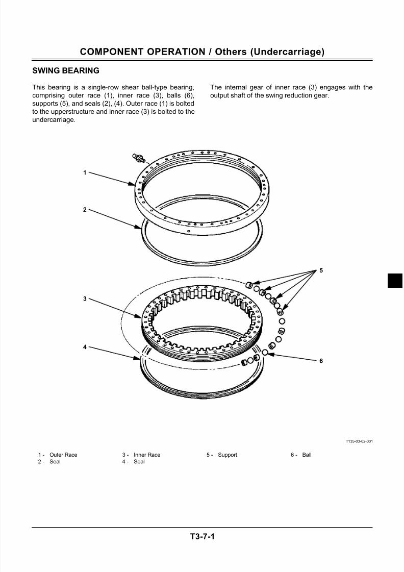
7/24/2019 t03 hitachi
http://slidepdf.com/reader/full/t03-hitachi 101/104
COMPONENT OPERATION / Others (Undercarriage)
T3-7-1
SWING BEARING
This bearing is a single-row shear ball-type bearing,
comprising outer race (1), inner race (3), balls (6),
supports (5), and seals (2), (4). Outer race (1) is bolted
to the upperstructure and inner race (3) is bolted to the
undercarriage.
The internal gear of inner race (3) engages with the
output shaft of the swing reduction gear.
T135-03-02-001
1 - Outer Race 3 - Inner Race 5 - Support 6 - Ball
2 - Seal 4 - Seal
1
2
3
4
5
6
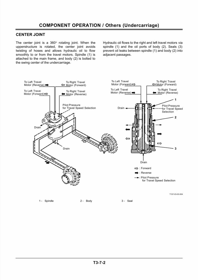
7/24/2019 t03 hitachi
http://slidepdf.com/reader/full/t03-hitachi 102/104
COMPONENT OPERATION / Others (Undercarriage)
T3-7-2
CENTER JOINT
The center joint is a 360° rotating joint. When the
upperstructure is rotated, the center joint avoids
twisting of hoses and allows hydraulic oil to flow
smoothly to or from the travel motors. Spindle (1) is
attached to the main frame, and body (2) is bolted to
the swing center of the undercarriage.
Hydraulic oil flows to the right and left travel motors via
spindle (1) and the oil ports of body (2). Seals (3)
prevent oil leaks between spindle (1) and body (2) into
adjacent passages.
T157-03-02-004
1 - Spindle 2 - Body 3 - Seal
To Right TravelMotor (Forward)
To Left TravelMotor (Reverse)
To Left TravelMotor (Forward)
Pilot Pressurefor Travel Speed Selection
Pilot Pressurefor Travel SpeedSelection
: Pilot Pressure for Travel Speed Selection
: Reverse
: Forward
Drain
Drain
Drain
Drain
To Right TravelMotor (Reverse)
To Right TravelMotor (Reverse)
To Right TravelMotor (Forward)
To Left TravelMotor (Forward)
To Left TravelMotor (Reverse)
1
2
3

7/24/2019 t03 hitachi
http://slidepdf.com/reader/full/t03-hitachi 103/104
COMPONENT OPERATION / Others (Undercarriage)
T3-7-3
TRACK ADJUSTER
The track adjuster located on the side frame is
composed of spring (5) and adjuster cylinder (6).
Spring (5) absorbs loads applied to the front idler.
Adjuster cylinder (6) adjusts track sag.
• Grease is applied through grease fitting into
chamber A of adjuster cylinder (6) as illustrated
below. The pressure of the grease pushes piston
rod (8) out and decreases track sag.
• To increases track sag, loosen valve (1) 1 to 1.5
turns counterclockwise to release grease from the
track adjuster cylinder through the grease
discharge hole.
CAUTION: Do not loosen valve (1) quickly or
loosen too much since high-pressure grease
in the adjusting cylinder may spout out.
Loosen carefully, keeping body parts and
face away from valve (1).
Never loosen grease fitting.
M104-07-119
T135-03-05-001
1 - Valve 3 - Washer 5 - Spring 7 - Flange
2 - Nut 4 - Spacer 6 - Adjuster Cylinder 8 - Piston Rod
1
2 3
Grease Discharge Hole
4
Grease Fitting
5 6 7 81 a
7/24/2019 t03 hitachi
http://slidepdf.com/reader/full/t03-hitachi 104/104
COMPONENT OPERATION / Others (Undercarriage)
(Blank)