t. sakai, s. fukushima, and k. ito electronic navigation research institute, japan t. sakai, s....
TRANSCRIPT

T. Sakai, S. Fukushima, and K. ItoElectronic Navigation Research Institute, Japan
T. Sakai, S. Fukushima, and K. ItoElectronic Navigation Research Institute, Japan
Recent Development ofQZSS L1-SAIF Master Station
Recent Development ofQZSS L1-SAIF Master Station
ION ITM 2010ION ITM 2010San Diego, CASan Diego, CA
Jan. 25-27, 2010Jan. 25-27, 2010

ION ITM 25-27 Jan. 2010 - ENRIION ITM 25-27 Jan. 2010 - ENRI
SSLIDELIDE 22IntroductionIntroduction
• QZSS (Quasi-Zenith Satellite System) programQZSS (Quasi-Zenith Satellite System) program::– Regional navigation service broadcast from high-elevation angle by three satelliRegional navigation service broadcast from high-elevation angle by three satelli
tes on the inclined geosynchronous (quasi-zenith) orbit;tes on the inclined geosynchronous (quasi-zenith) orbit;
– Currently working for launch of the first satellite in 2010 Summer season;Currently working for launch of the first satellite in 2010 Summer season;
– Broadcast GPS-compatible supplemental signals on three frequencies and two Broadcast GPS-compatible supplemental signals on three frequencies and two augmentation signals, L1-SAIF and LEX.augmentation signals, L1-SAIF and LEX.
• L1-SAIF L1-SAIF (Submeter-class Augmentation with Integrity Function) signal offers(Submeter-class Augmentation with Integrity Function) signal offers::– Sub-meter accuracy wide-area differential correction service;Sub-meter accuracy wide-area differential correction service;
– Integrity function for safety of mobile users; andIntegrity function for safety of mobile users; and
– Ranging function for position availability; all on L1 single frequency.Ranging function for position availability; all on L1 single frequency.
• ENRI has been developing L1-SAIF signal and facilityENRI has been developing L1-SAIF signal and facility::– Signal design: GPS/SBAS-compatible on L1;Signal design: GPS/SBAS-compatible on L1;
– Implemented L1-SAIF Master Station (L1SMS) which generates augmentation Implemented L1-SAIF Master Station (L1SMS) which generates augmentation message stream in realtime and transmits it to QZSS MCS.message stream in realtime and transmits it to QZSS MCS.

ION ITM 25-27 Jan. 2010 - ENRIION ITM 25-27 Jan. 2010 - ENRI
SSLIDELIDE 33
Part 1Part 1
Overview of QZSS ProgramOverview of QZSS Program

ION ITM 25-27 Jan. 2010 - ENRIION ITM 25-27 Jan. 2010 - ENRI
SSLIDELIDE 44QZSS ConceptQZSS Concept
QZSQZSGPS/GEOGPS/GEO
• Signal from high elevation angleSignal from high elevation angle
• Applicable to navigation services for Applicable to navigation services for mountain area and urban canyonmountain area and urban canyon
• Footprint of QZS orbitFootprint of QZS orbit• Centered 137ECentered 137E• Eccentricity 0.1, Inclination 45degEccentricity 0.1, Inclination 45deg

ION ITM 25-27 Jan. 2010 - ENRIION ITM 25-27 Jan. 2010 - ENRI
SSLIDELIDE 55QZSS ProgramQZSS Program
• QZSS (Quasi-Zenith Satellite System) programQZSS (Quasi-Zenith Satellite System) program::– Japan has been developing QZSS since FY 2003;Japan has been developing QZSS since FY 2003;
– Regional navigation service broadcast from high-elevation angle by three satelliteRegional navigation service broadcast from high-elevation angle by three satellites on the inclined geosynchronous (quasi-zenith) orbit;s on the inclined geosynchronous (quasi-zenith) orbit;
– Broadcast GPS-compatible supplemental signals on three frequencies (L1 C/A, LBroadcast GPS-compatible supplemental signals on three frequencies (L1 C/A, L1C, L2C, and L5) and two augmentation signals, L1-SAIF and LEX.1C, L2C, and L5) and two augmentation signals, L1-SAIF and LEX.
• Participating institutesParticipating institutes::– JAXA (JAXA (Japan Aerospace Exploration AgencyJapan Aerospace Exploration Agency):): Development and operation of the spac Development and operation of the spac
e segment and Master Control Station;e segment and Master Control Station;– NICT (NICT (National Institute of Information and Communication TechnologyNational Institute of Information and Communication Technology):): Frequency stan Frequency stan
dard and time keeping system including Uplink Station;dard and time keeping system including Uplink Station;– AIST (AIST (National Institute of Advanced Industrial Science and TechnologyNational Institute of Advanced Industrial Science and Technology):): Time synch-ron Time synch-ron
ization between space and ground;ization between space and ground;– GSI (GSI (Geographical Survey InstituteGeographical Survey Institute):): Survey-grade carrier-based positioning service; Survey-grade carrier-based positioning service;– ENRI (ENRI (Electronic Navigation Research InstituteElectronic Navigation Research Institute):): Navigation-grade WADGPS service b Navigation-grade WADGPS service b
roadcast by L1-SAIF signal.roadcast by L1-SAIF signal.

ION ITM 25-27 Jan. 2010 - ENRIION ITM 25-27 Jan. 2010 - ENRI
SSLIDELIDE 66Overall ArchitectureOverall Architecture
Function distributed in each institute
Timing management by NICT, WADGPS service by ENRI, etc.
SLR SiteSLR SiteMonitor Monitor StationStation NW NW
GPS Satellites
TT&C / NAV Msg TT&C / NAV Msg Uplink StationUplink Station
GEONETGEONET(GSI)(GSI)
Time Mgmt Time Mgmt StationStation
TWSTFT: Two Way Satellite Time and Frequency TransferTWSTFT: Two Way Satellite Time and Frequency Transfer
QZS SatelliteQZS Satellite
User ReceiverUser Receiver
SatelliteLaser Ranging
Navigation SignalsL1: 1575.42 MHzL2: 1227.60 MHzL5: 1176.45 MHzLEX: 1278.75 MHz
TT&C / NAV Message Uplink
TWSTFTUp: 4.43453GHz
Down: 12.30669GHz
(Courtesy: JAXA QZSS PT)(Courtesy: JAXA QZSS PT)
Master Control Master Control Station (MCS)Station (MCS)

ION ITM 25-27 Jan. 2010 - ENRIION ITM 25-27 Jan. 2010 - ENRI
SSLIDELIDE 77Space Segment: QZS-1Space Segment: QZS-1
L-band Helical Array Antenna
L1-SAIF Antenna
Laser Reflector
C-band TTC Antenna
Radiation Cooled TWTTWSTFT Antenna
25.3m
MassApprox. 1,800kg (dry) (NAV Payload: Approx. 320kg)
PowerApprox. 5.3 kW (EOL) (NAV Payload: Approx. 1.9kW)
Design Life 10 years

ION ITM 25-27 Jan. 2010 - ENRIION ITM 25-27 Jan. 2010 - ENRI
SSLIDELIDE 88
• Supplemental signalsSupplemental signals::– GPS-compatible L1C/A, L2C, L5, and L1C signals working with GPS; For GPS-compatible L1C/A, L2C, L5, and L1C signals working with GPS; For
improving availability of navigation;improving availability of navigation;– With minimum modifications from GPS signal specifications;With minimum modifications from GPS signal specifications;– Coordination with GPS Wing on broadcasting L1C signal;Coordination with GPS Wing on broadcasting L1C signal;– JAXA is responsible for all supplemental signals.JAXA is responsible for all supplemental signals.
• Augmentation signalsAugmentation signals::– Augmentation to GPS; Possibly plus Galileo;Augmentation to GPS; Possibly plus Galileo;– L1-SAIF: Compatible with SBAS; reasonable performance for mobile users;L1-SAIF: Compatible with SBAS; reasonable performance for mobile users;– LEX: For carrier-based experimental purposes; member organizations may LEX: For carrier-based experimental purposes; member organizations may
use as 2kbps experimental data channel;use as 2kbps experimental data channel;– ENRI is working for L1-SAIF while JAXA is developing LEX.ENRI is working for L1-SAIF while JAXA is developing LEX.
• Interface Specification: IS-QZSSInterface Specification: IS-QZSS::– Specifies RF signal interface between QZS satellite and user receiver;Specifies RF signal interface between QZS satellite and user receiver;– First issue: Jan. 2007; Maintained by JAXA.First issue: Jan. 2007; Maintained by JAXA.
QZSS SignalsQZSS Signals

ION ITM 25-27 Jan. 2010 - ENRIION ITM 25-27 Jan. 2010 - ENRI
SSLIDELIDE 99QZSS Frequency PlanQZSS Frequency Plan
SignalSignal ChannelChannel FrequencyFrequency BandwidthBandwidth Min. Rx PowerMin. Rx Power
QZS-L1CQZS-L1CL1CDL1CD
1575.42 MHz1575.42 MHz
24 MHz24 MHz ––163.0 dBW163.0 dBW
L1CPL1CP 24 MHz24 MHz – – 158.25 dBW158.25 dBW
QZS-L1-C/AQZS-L1-C/A 24 MHz24 MHz – – 158.5 dBW158.5 dBW
QZS-L1-SAIFQZS-L1-SAIF 24 MHz24 MHz – – 161.0 dBW161.0 dBW
QZS-L2CQZS-L2C 1227.6 MHz1227.6 MHz 24 MHz24 MHz – – 160.0 dBW160.0 dBW
QZS-L5QZS-L5L5IL5I
1176.45 MHz1176.45 MHz25 MHz25 MHz – – 157.9 dBW157.9 dBW
L5QL5Q 25 MHz25 MHz – – 157.9 dBW157.9 dBW
QZS-LEXQZS-LEX 1278.75 MHz1278.75 MHz 42 MHz42 MHz – – 155.7 dBW155.7 dBW
Find detail in IS-QZSS document.Find detail in IS-QZSS document.
ION ITM 25-27 Jan. 2010 - ENRIION ITM 25-27 Jan. 2010 - ENRI
SSLIDELIDE 1010
Part 2Part 2
L1-SAIF Signal DesignL1-SAIF Signal Design

ION ITM 25-27 Jan. 2010 - ENRIION ITM 25-27 Jan. 2010 - ENRI
SSLIDELIDE 1111
• QZSS will broadcast wide-area augmentation signalQZSS will broadcast wide-area augmentation signal::– Called L1-SAIF (Submeter-class Augmentation with Integrity Function);Called L1-SAIF (Submeter-class Augmentation with Integrity Function);
– Developed by ENRI.Developed by ENRI.
• L1-SAIF signal offersL1-SAIF signal offers::– Wide-area differential correction service for improving position accuracy; TargeWide-area differential correction service for improving position accuracy; Targe
t accuracy: 1 meter for horizontal;t accuracy: 1 meter for horizontal;
– Integrity function for safety of mobile users; andIntegrity function for safety of mobile users; and
– Ranging function for position availability.Ranging function for position availability.
• Interoperable with GPS L1C/A and fully compatible with SBASInteroperable with GPS L1C/A and fully compatible with SBAS::– Broadcast on L1 freq. with RHCP; Common antenna and RF front-end;Broadcast on L1 freq. with RHCP; Common antenna and RF front-end;
– Modulated by BPSK with C/A code;Modulated by BPSK with C/A code;
– 250 bps data rate with 1/2 FEC; message structure is identical with SBAS;250 bps data rate with 1/2 FEC; message structure is identical with SBAS;
– Differences: Large Doppler and additional messages.Differences: Large Doppler and additional messages.
QZSS L1-SAIF SignalQZSS L1-SAIF Signal

ION ITM 25-27 Jan. 2010 - ENRIION ITM 25-27 Jan. 2010 - ENRI
SSLIDELIDE 1212WADGPS ConceptWADGPS Concept
Orbit CorrectionOrbit Correction
TroposphereTroposphere
IonosphereIonosphere
Ionospheric CorrectionIonospheric Correction
Tropospheric CorrectionTropospheric Correction
Clock CorrectionClock Correction• Same contribution to any user Same contribution to any user
location;location;• Not a function of location;Not a function of location;• Needs fast correction. Needs fast correction.
• Different contribution to different Different contribution to different user location;user location;
• Not a function of user location; but Not a function of user location; but a function of line-of-sight direction;a function of line-of-sight direction;
• Long-term correction.Long-term correction.
• Function of user location;Function of user location;• Up to 100 meters;Up to 100 meters;• Vertical structure may be Vertical structure may be
described as a thin shell.described as a thin shell.
• Function of user location, especially height of user;Function of user location, especially height of user;• Up to 20 meters;Up to 20 meters;• Can be corrected enough by a fixed model.Can be corrected enough by a fixed model.

ION ITM 25-27 Jan. 2010 - ENRIION ITM 25-27 Jan. 2010 - ENRI
SSLIDELIDE 1313SBAS/L1-SAIF Message StructureSBAS/L1-SAIF Message Structure
PreamblePreamble8 bits8 bits
Message TypeMessage Type6 bits6 bits
Data FieldData Field212 bits212 bits
CRC parityCRC parity24 bits24 bits
250 bits per second
MTMT
00
11
22~~ 55
66
77
99
1010
1212
1717
1818
ContentsContents
Test modeTest mode
PRN maskPRN mask
Fast correction & UDREFast correction & UDRE
UDREUDRE
Degradation factor for FCDegradation factor for FC
GEO ephemerisGEO ephemeris
Degradation parameterDegradation parameter
SBAS time informationSBAS time information
GEO almanacGEO almanac
IGP maskIGP mask
IntervalInterval[s][s]
66
120120
6060
66
120120
120120
120120
300300
300300
300300
2424
2525
2626
2727
2828
6363
FC & LTCFC & LTC
Long-term correctionLong-term correction
Ionospheric delay & GIVEIonospheric delay & GIVE
SBAS service messageSBAS service message
Clock-ephemeris covarianceClock-ephemeris covariance
Null messageNull message
66
120120
300300
300300
120120
——
MTMT ContentsContents IntervalInterval[s][s]
Transmitted FirstTransmitted First

ION ITM 25-27 Jan. 2010 - ENRIION ITM 25-27 Jan. 2010 - ENRI
SSLIDELIDE 1414SBAS/L1-SAIF Message (1)SBAS/L1-SAIF Message (1)
Message TypeMessage Type ContentsContents CompatibilityCompatibility StatusStatus
00 Test modeTest mode BothBoth FixedFixed
11 PRN maskPRN mask BothBoth FixedFixed
2 to 52 to 5 Fast correction & UDREFast correction & UDRE BothBoth FixedFixed
66 UDREUDRE BothBoth FixedFixed
77 Degradation factor for FCDegradation factor for FC BothBoth FixedFixed
1010 Degradation parameterDegradation parameter BothBoth FixedFixed
1818 IGP maskIGP mask BothBoth FixedFixed
2424 Mixed fast/long-term correctionMixed fast/long-term correction BothBoth FixedFixed
2525 Long-term correctionLong-term correction BothBoth FixedFixed
2626 Ionospheric delay & GIVEIonospheric delay & GIVE BothBoth FixedFixed
99 GEO ephemerisGEO ephemeris SBASSBAS FixedFixed
1717 GEO almanacGEO almanac SBASSBAS FixedFixed
1212 SBAS network timeSBAS network time SBASSBAS FixedFixed
88 ReservedReserved SBASSBAS FixedFixed

ION ITM 25-27 Jan. 2010 - ENRIION ITM 25-27 Jan. 2010 - ENRI
SSLIDELIDE 1515SBAS/L1-SAIF Message (2)SBAS/L1-SAIF Message (2)
Message TypeMessage Type ContentsContents CompatibilityCompatibility StatusStatus
2727 SBAS service messageSBAS service message SBASSBAS FixedFixed
29 to 5129 to 51 (Undefined)(Undefined) —— ——
2828 Clock-ephemeris covarianceClock-ephemeris covariance BothBoth FixedFixed
6262 ReservedReserved BothBoth FixedFixed
6363 Null messageNull message BothBoth FixedFixed
5252 TGP maskTGP mask L1-SAIFL1-SAIF TentativeTentative
5656 Intersignal biasesIntersignal biases L1-SAIFL1-SAIF TentativeTentative
5757 (Ephemeris-related parameter)(Ephemeris-related parameter) L1-SAIFL1-SAIF TBDTBD
5858 QZS ephemerisQZS ephemeris L1-SAIFL1-SAIF TentativeTentative
5959 (QZS almanac)(QZS almanac) L1-SAIFL1-SAIF TBDTBD
6060 (Regional information)(Regional information) L1-SAIFL1-SAIF TBDTBD
6161 ReservedReserved L1-SAIFL1-SAIF TentativeTentative
5533 Tropospheric delayTropospheric delay L1-SAIFL1-SAIF TentativeTentative
54 to 5554 to 55 (Advanced Ionospheric delay)(Advanced Ionospheric delay) L1-SAIFL1-SAIF TBDTBD

ION ITM 25-27 Jan. 2010 - ENRIION ITM 25-27 Jan. 2010 - ENRI
SSLIDELIDE 1616GPS/L1-SAIF SimulatorGPS/L1-SAIF Simulator
• GPS/L1-SAIF SimulatorGPS/L1-SAIF Simulator::– Simulates GPS L1 C/A and QZSS L1-SAIF signals;Simulates GPS L1 C/A and QZSS L1-SAIF signals;
– Generates RF signals based on pre-defined GPS and QZSS constellation Generates RF signals based on pre-defined GPS and QZSS constellation scenario and signal specificationsscenario and signal specifications
of IS-GPS and IS-QZSS;of IS-GPS and IS-QZSS;
– Manufactured by Spirent, modifyingManufactured by Spirent, modifying
GPS/SBAS simulator GSS7700.GPS/SBAS simulator GSS7700.
• Special function for experimentSpecial function for experiment::– Added extra command to inputAdded extra command to input
L1-SAIF message from EthernetL1-SAIF message from Ethernet
port (TCP/IP);port (TCP/IP);
– L1-SAIF message is either inputL1-SAIF message is either input
by the command externally orby the command externally or
generated by the simulator internally.generated by the simulator internally.
GPS/L1-SAIFGPS/L1-SAIFSimulatorSimulator
GPS/L1-SAIFGPS/L1-SAIFReceiverReceiver

ION ITM 25-27 Jan. 2010 - ENRIION ITM 25-27 Jan. 2010 - ENRI
SSLIDELIDE 1717GPS/L1-SAIF ReceiverGPS/L1-SAIF Receiver
• Prototype GPS/L1-SAIF ReceiverPrototype GPS/L1-SAIF Receiver::– Receives GPS L1 C/A and QZSS L1-SAIF signals;Receives GPS L1 C/A and QZSS L1-SAIF signals;
– Decode and apply L1-SAIF message as defined by IS-QZSS;Decode and apply L1-SAIF message as defined by IS-QZSS;
– Manufactured by Furuno Electric.Manufactured by Furuno Electric.
• Special function for experimentSpecial function for experiment::– L1-SAIF message can be input fromL1-SAIF message can be input from
Ethernet port (TCP/IP)Ethernet port (TCP/IP) as well asas well as
L1-SAIF signal on RF;L1-SAIF signal on RF;
– Enable to process L1-SAIF and SBAS,Enable to process L1-SAIF and SBAS,
totally three, augmentation signalstotally three, augmentation signals
simultaneously;simultaneously;
– Portable equipage for experimentPortable equipage for experiment
at remote or on mobile.at remote or on mobile.
GPS/L1-SAIFGPS/L1-SAIFReceiverReceiver

ION ITM 25-27 Jan. 2010 - ENRIION ITM 25-27 Jan. 2010 - ENRI
SSLIDELIDE 1818RF Compatibility TestRF Compatibility Test
• Ranging function: The receiver output the proper position solution with pseudorange of Ranging function: The receiver output the proper position solution with pseudorange of L1-SAIF signal generated by the simulator;L1-SAIF signal generated by the simulator;
• Decoding message: The receiver decoded L1-SAIF message which matched with the Decoding message: The receiver decoded L1-SAIF message which matched with the message input to the simulator via Ethernet port; The command needs to be given 2-smessage input to the simulator via Ethernet port; The command needs to be given 2-second before the applicable time of transmission;econd before the applicable time of transmission;
• Successfully completed in Feb. 2009.Successfully completed in Feb. 2009.
GPS/L1-SAIFGPS/L1-SAIFSimulatorSimulator
GPS/L1-SAIFGPS/L1-SAIFReceiverReceiver
TCP/IPTCP/IP
RF CableRF Cable
SpirentSpirent Furuno ElectricFuruno Electric
FileFile
L1-SAIF MessageL1-SAIF Message
ScenarioScenario
Decoded MessageDecoded Message
CompareCompare
L1-SAIF SignalL1-SAIF Signal
ENRI (Chofu, Tokyo)ENRI (Chofu, Tokyo)

ION ITM 25-27 Jan. 2010 - ENRIION ITM 25-27 Jan. 2010 - ENRI
SSLIDELIDE 1919RF Compatibility TestRF Compatibility Test
Standalone GPSStandalone GPS L1-SAIF AugmentationL1-SAIF Augmentation
2008/9/10 00:05:00 to 06:00:00 (6 hours)2008/9/10 00:05:00 to 06:00:00 (6 hours)
OK!OK!

ION ITM 25-27 Jan. 2010 - ENRIION ITM 25-27 Jan. 2010 - ENRI
SSLIDELIDE 2020
Part 3Part 3
L1-SAIF Master Station (L1SMS)L1-SAIF Master Station (L1SMS)

ION ITM 25-27 Jan. 2010 - ENRIION ITM 25-27 Jan. 2010 - ENRI
SSLIDELIDE 2121
• L1-SAIF Master Station (L1SMS):L1-SAIF Master Station (L1SMS):– Generates L1-SAIF message stream in realtime and transmits it to QZSS MCS deGenerates L1-SAIF message stream in realtime and transmits it to QZSS MCS de
veloped by and installed at JAXA;veloped by and installed at JAXA;– Installed at ENRI, Tokyo; 90km from JAXA Tsukuba Space Center;Installed at ENRI, Tokyo; 90km from JAXA Tsukuba Space Center;– Subsystems: GEONET Server, Primary Receiver, Interface Processor, Message GSubsystems: GEONET Server, Primary Receiver, Interface Processor, Message G
enerator, Ionosphere Processor, Troposphere Processor, and Batch Processor.enerator, Ionosphere Processor, Troposphere Processor, and Batch Processor.
ENRI L1SMSENRI L1SMS
L1SMSL1SMSGEONETGEONET
QZSQZS
QZSS MCSQZSS MCS
GPSGPS
MeasuredMeasuredDataData
L1-SAIFL1-SAIFMessageMessage
GSIGSI ENRIENRI JAXAJAXA
L1-S
AIF S
ignal
L1-S
AIF S
ignalL1C/A, L2P
L1C/A, L2PL1
C/A, L
2P
L1C/A
, L2P K-band
K-bandClosedClosedLoopLoop

ION ITM 25-27 Jan. 2010 - ENRIION ITM 25-27 Jan. 2010 - ENRI
SSLIDELIDE 2222L1SMS Installed at ENRIL1SMS Installed at ENRI
StorageStorage
Router toRouter toGEONETGEONET
I/FI/F
UPSUPSUPSUPS
MessageMessageGeneratorGenerator
GEONETGEONETServerServer
StorageStorage
Ionosphere Ionosphere ProcessorProcessor
StorageStorage

ION ITM 25-27 Jan. 2010 - ENRIION ITM 25-27 Jan. 2010 - ENRI
SSLIDELIDE 2323Configuration of L1SMSConfiguration of L1SMS
GEONET ServerGEONET Server
Ionosphere ProcessorIonosphere ProcessorTroposphere ProcessorTroposphere Processor
Message GeneratorMessage Generator(L1SMG)(L1SMG)
GEONETGEONET
Batch ProcessorBatch Processor(IFB Estimation)(IFB Estimation)
L1SMS Batch SubsystemL1SMS Batch Subsystem
L1SMS Realtime SubsystemsL1SMS Realtime Subsystems
TCP/IPTCP/IP
MessageMessageOutputOutput
via TCP/IPvia TCP/IP
ObservationObservationFile (RINEX)File (RINEX)
via FTPvia FTP
IFBIFBEstimatesEstimates
Primary ReceiverPrimary Receiver
Interface ProcessorInterface Processor
Dual Freq. ANTDual Freq. ANT

ION ITM 25-27 Jan. 2010 - ENRIION ITM 25-27 Jan. 2010 - ENRI
SSLIDELIDE 2424JAXA-ENRI Interface (G-ICD)JAXA-ENRI Interface (G-ICD)
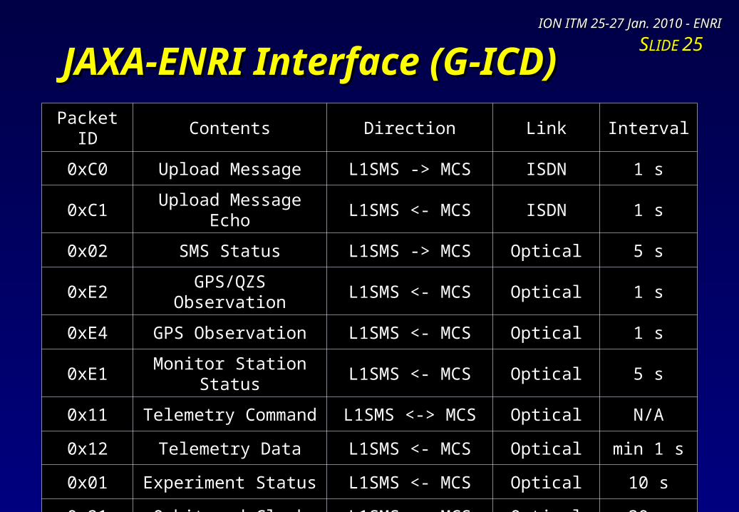
• Ground System ICD (Interface Control Document)Ground System ICD (Interface Control Document)::– Defines interface between JAXA QZSS MCS and ENRI L1SMS;Defines interface between JAXA QZSS MCS and ENRI L1SMS;– First issue: Jan. 2008;First issue: Jan. 2008;– Specifies data stream on TCP/IP connection bit-by-bit.Specifies data stream on TCP/IP connection bit-by-bit.
• Dual communication lines for redundancyDual communication lines for redundancy::– ISDN (64kbps) and optical (1.5Mbps) links;ISDN (64kbps) and optical (1.5Mbps) links;– Low-rate ISDN: Reliable transmission for uploading L1-SAIF message;Low-rate ISDN: Reliable transmission for uploading L1-SAIF message;– High-rate optical link: Exchange station status and monitor station observation;High-rate optical link: Exchange station status and monitor station observation;– Only for the experiment; no definition of service levels.Only for the experiment; no definition of service levels.
L1SMSL1SMS
MCS AMCS A
MCS BMCS B
RouterRouterRouterRouter
RouterRouterRouterRouter
ISDNISDN
OpticalOptical
Upload MessageUpload Message
Other DataOther Data
JAXAJAXAENRIENRI
ION ITM 25-27 Jan. 2010 - ENRIION ITM 25-27 Jan. 2010 - ENRI
SSLIDELIDE 2525JAXA-ENRI Interface (G-ICD)JAXA-ENRI Interface (G-ICD)
Packet ID Contents Direction Link Interval
0xC0 Upload Message L1SMS -> MCS ISDN 1 s
0xC1 Upload Message Echo L1SMS <- MCS ISDN 1 s
0x02 SMS Status L1SMS -> MCS Optical 5 s
0xE2 GPS/QZS Observation L1SMS <- MCS Optical 1 s
0xE4 GPS Observation L1SMS <- MCS Optical 1 s
0xE1 Monitor Station Status L1SMS <- MCS Optical 5 s
0x11 Telemetry Command L1SMS <-> MCS Optical N/A
0x12 Telemetry Data L1SMS <- MCS Optical min 1 s
0x01 Experiment Status L1SMS <- MCS Optical 10 s
0x21 Orbit and Clock L1SMS <- MCS Optical 30 s

ION ITM 25-27 Jan. 2010 - ENRIION ITM 25-27 Jan. 2010 - ENRI
SSLIDELIDE 2626Closed-Loop Interface TestClosed-Loop Interface Test
• Interface test between JAXA MCS and ENRI L1Interface test between JAXA MCS and ENRI L1SMS and between Nav payload and receiver;SMS and between Nav payload and receiver;
• Checked the format of transmitted and received Checked the format of transmitted and received data packets, then compared log files bit-by-bit;data packets, then compared log files bit-by-bit;
• Successfully completed in Dec. 2008.Successfully completed in Dec. 2008.
HUBHUBLANLAN
Upload MessageUpload Message JAXAJAXAENRIENRI
LogLogLogLog
MCS BMCS B
NavigationNavigationPayload EMPayload EM
RF CableRF CableL1-SAIF SignalL1-SAIF Signal
L1SMSL1SMSSimulatorSimulator
HUBHUB
NEC (Fuchu, Tokyo)NEC (Fuchu, Tokyo)
LogLog
GPS/L1-SAIFGPS/L1-SAIFReceiverReceiver
L1SMS SimL1SMS Sim
Nav payloadNav payload
ReceiverReceiver

ION ITM 25-27 Jan. 2010 - ENRIION ITM 25-27 Jan. 2010 - ENRI
SSLIDELIDE 2727JAXA-ENRI Interface TestJAXA-ENRI Interface Test
• Interface test between two facilities, JAXA MCS and ENRI L1SMS, with the complete Interface test between two facilities, JAXA MCS and ENRI L1SMS, with the complete configuration of communication lines;configuration of communication lines;
• Confirmed the format of transmitted and received data packets, then compared log Confirmed the format of transmitted and received data packets, then compared log files taken at both facilities bit-by-bit;files taken at both facilities bit-by-bit;
• Successfully completed in Jan. 2010.Successfully completed in Jan. 2010.
L1SMSL1SMSSimulatorSimulator
RouterRouterRouterRouter
RouterRouterRouterRouter
ISDNISDN
OpticalOptical
Upload MessageUpload Message
Other DataOther Data
JAXAJAXAENRIENRI
LogLog LogLog
MCS AMCS A
MCS BMCS B
ENRI (Chofu, Tokyo)ENRI (Chofu, Tokyo) JAXA (Tsukuba)JAXA (Tsukuba)

ION ITM 25-27 Jan. 2010 - ENRIION ITM 25-27 Jan. 2010 - ENRI
SSLIDELIDE 2828
Part 4Part 4
Realtime Operation TestRealtime Operation Test

ION ITM 25-27 Jan. 2010 - ENRIION ITM 25-27 Jan. 2010 - ENRI
SSLIDELIDE 2929Realtime Operation TestRealtime Operation Test
• Tested performance of the ICP Tested performance of the ICP Implemented as a subsystem of Implemented as a subsystem of L1SMS; running with L1SMG;L1SMS; running with L1SMG;
• Analyzed user position error at 14 Analyzed user position error at 14 evaluation locations; Numbered from evaluation locations; Numbered from North to South;North to South;
• Used GEONET stations as all Used GEONET stations as all monitor stations and evaluation sites.monitor stations and evaluation sites.
GMS Stations (6) for L1SMGGMS Stations (6) for L1SMG
L1-SAIF Experimental AreaL1-SAIF Experimental Area
IMS Station (200) for ICPIMS Station (200) for ICP
Evaluation Locations (14)Evaluation Locations (14)

ION ITM 25-27 Jan. 2010 - ENRIION ITM 25-27 Jan. 2010 - ENRI
SSLIDELIDE 3030Results – Position Error SampleResults – Position Error Sample
• Example of user positioning error at Site Example of user positioning error at Site #5 93022 Choshi (East of Tokyo);#5 93022 Choshi (East of Tokyo);
• ICP: 200 IMS, 5-deg IGP, 0th Order Fit;ICP: 200 IMS, 5-deg IGP, 0th Order Fit;
• Period: 16-21 Jan. 2009 (5 days).Period: 16-21 Jan. 2009 (5 days).
MSAS AugmentationMSAS Augmentation
Standalone GPSStandalone GPS
L1-SAIF AugmentationL1-SAIF Augmentation
SystemHorizontal
ErrorVertical Error
L1-SAIFRMS 0.23 m 0.36 m
MAX 1.67 m 3.35 m
MSASRMS 0.46 m 0.59 m
MAX 1.73 m 2.43 m
Standalone GPS
RMS 1.25 m 2.99 m
MAX 4.30 m 8.11 m
ION ITM 25-27 Jan. 2010 - ENRIION ITM 25-27 Jan. 2010 - ENRI
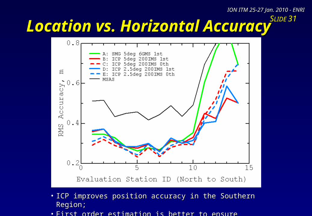
SSLIDELIDE 3131Location vs. Horizontal AccuracyLocation vs. Horizontal Accuracy
• ICP improves position accuracy in the Southern Region;ICP improves position accuracy in the Southern Region;• First order estimation is better to ensure accuracy.First order estimation is better to ensure accuracy.

ION ITM 25-27 Jan. 2010 - ENRIION ITM 25-27 Jan. 2010 - ENRI
SSLIDELIDE 3232Location vs. Vertical AccuracyLocation vs. Vertical Accuracy
• 1 meter accuracy is achievable even for vertical direction;1 meter accuracy is achievable even for vertical direction;• Note that these results associate with solar minimum phase.Note that these results associate with solar minimum phase.

ION ITM 25-27 Jan. 2010 - ENRIION ITM 25-27 Jan. 2010 - ENRI
SSLIDELIDE 3333Realtime Operation Using GEORealtime Operation Using GEO
• ETS-VIII satelliteETS-VIII satellite::– Engineering Test Satellite for mobile communication and onboard clock of Engineering Test Satellite for mobile communication and onboard clock of
navigation-grade;navigation-grade;– Geostationary satellite with very largeGeostationary satellite with very large
(19m) folding antenna;(19m) folding antenna;– Launched in Dec. 2006 by JAXA.Launched in Dec. 2006 by JAXA.
• ENRI joined the experimentENRI joined the experiment::– Communication experiment betweenCommunication experiment between
two fixed points;two fixed points;– L1SMG transmitted L1-SAIF messageL1SMG transmitted L1-SAIF message
to ETS-VIII;to ETS-VIII;– Received L1-SAIF message was inputReceived L1-SAIF message was input
to the GPS/L1-SAIF receiver andto the GPS/L1-SAIF receiver and
processed properly;processed properly;– Successfully completed in Feb. 2009.Successfully completed in Feb. 2009. ETS-VIII SatelliteETS-VIII Satellite

ION ITM 25-27 Jan. 2010 - ENRIION ITM 25-27 Jan. 2010 - ENRI
SSLIDELIDE 3434Uplink from TokyoUplink from Tokyo
L1-SAIF Master StationL1-SAIF Master Station
ETS-VIII SatelliteETS-VIII SatelliteEthernetEthernet
ETS-VIII Terminal EquipmentETS-VIII Terminal Equipment
RF signalRF signal
SATCOM AntennaSATCOM Antenna
L1-SAIF messageL1-SAIF message

ION ITM 25-27 Jan. 2010 - ENRIION ITM 25-27 Jan. 2010 - ENRI
SSLIDELIDE 3535Downlink to SendaiDownlink to Sendai
GPS/L1-SAIFGPS/L1-SAIFReceiverReceiver
ETS-VIII Terminal EquipmentETS-VIII Terminal Equipment
SATCOM AntennaSATCOM Antenna
ETS-VIII SatelliteETS-VIII Satellite
RF signalRF signal EthernetEthernet
GPS signalGPS signalL1-SAIF messageL1-SAIF message
(400km away from Tokyo)(400km away from Tokyo)

ION ITM 25-27 Jan. 2010 - ENRIION ITM 25-27 Jan. 2010 - ENRI
SSLIDELIDE 3636L1-SAIF Receiver OutputL1-SAIF Receiver Output
2009/2/17 01:21:39 to 07:23:14 (6 hours)2009/2/17 01:21:39 to 07:23:14 (6 hours)
Standalone GPSStandalone GPS L1-SAIF AugmentationL1-SAIF Augmentation
H Error RMS = 0.412mH Error RMS = 0.412mV Error RMS = 0.464mV Error RMS = 0.464m
H Error RMS = 1.221mH Error RMS = 1.221mV Error RMS = 4.043mV Error RMS = 4.043m

ION ITM 25-27 Jan. 2010 - ENRIION ITM 25-27 Jan. 2010 - ENRI
SSLIDELIDE 3737Stability TestStability Test
• Runs L1SMG for several monthsRuns L1SMG for several months::– To investigate stability of the software implemented in L1SMG;To investigate stability of the software implemented in L1SMG;– Period I: 2008/3/11 to 2008/5/24 (74 days);Period I: 2008/3/11 to 2008/5/24 (74 days);– Period II: 2008/6/10 to 2008/8/28 (79 days).Period II: 2008/6/10 to 2008/8/28 (79 days).
• Result: No major trouble:Result: No major trouble:– The software runs for the periods without human interaction;The software runs for the periods without human interaction;– User position accuracy was reasonable.User position accuracy was reasonable.
Site940030
Oga
93101
Omaezaki
940058
Takayama
940085
Tosashimizu
950491
Sata
Period IHor 0.362 0.363 0.362 0.423 0.502
Ver 0.517 0.536 0.548 0.608 0.739
Period IIHor 0.460 0.440 0.347 0.416 0.552
Ver 0.657 1.236 0.678 0.699 1.371
Resulted User Position Accuracy at Some Locations [unit: m]Resulted User Position Accuracy at Some Locations [unit: m]

ION ITM 25-27 Jan. 2010 - ENRIION ITM 25-27 Jan. 2010 - ENRI
SSLIDELIDE 3838ConclusionConclusion
• ENRI has been developing L1-SAIF signalENRI has been developing L1-SAIF signal::– Signal design: GPS/SBAS-compatible;Signal design: GPS/SBAS-compatible;
– Implemented L1-SAIF Master Station (L1SMS) which generates augmentation messImplemented L1-SAIF Master Station (L1SMS) which generates augmentation message stream in realtime and transmit it to QZSS MCS.age stream in realtime and transmit it to QZSS MCS.
• Completed, so farCompleted, so far::– Design of L1-SAIF signal and publishing as a part of IS-QZSS;Design of L1-SAIF signal and publishing as a part of IS-QZSS;
– Development of GPS/L1-SAIF simulator and receiver;Development of GPS/L1-SAIF simulator and receiver;
– Development of G-ICD between L1SMS and QZSS MCS, and interface test of them;Development of G-ICD between L1SMS and QZSS MCS, and interface test of them;
– Interface test at the closed-loop configuration including L1SMS, MCS, QZSS navigatInterface test at the closed-loop configuration including L1SMS, MCS, QZSS navigation payload, and GPS/L1-SAIF receiver;ion payload, and GPS/L1-SAIF receiver;
– Realtime operation test with/without geostationary satellite (ETS-VIII); andRealtime operation test with/without geostationary satellite (ETS-VIII); and
– Stability test of L1SMS.Stability test of L1SMS.
• Currently working forCurrently working for::– Final interface test at the full-configuration of ground/space systems;Final interface test at the full-configuration of ground/space systems;
– Preparation of performance experiment with the first QZS space vehicle.Preparation of performance experiment with the first QZS space vehicle.