systems - · pdf filesystems are transformations a discrete-time system his a transformation...
TRANSCRIPT

Systems

Systems are Transformations
A discrete-time system H is a transformation (a rule or formula) that maps adiscrete-time input signal x into a discrete-time output signal y
y = H{x}
x H y
DE
FIN
ITIO
N
Systems manipulate the information in signals
Examples:
• A speech recognition system converts acoustic waves of speech into text• A radar system transforms the received radar pulse to estimate the position and velocity of targets• A functional magnetic resonance imaging (fMRI) system transforms measurements of electron spin
into voxel-by-voxel estimates of brain activity• A 30 day moving average smooths out the day-to-day variability in a stock price
2

Signal Length and Systems
x H y
Recall that there are two kinds of signals: infinite-length and finite-length
Accordingly, we will consider two kinds of systems:
1 Systems that transform an infinite-length-signal x into an infinite-length signal y
2 Systems that transform a length-N signal x into a length-N signal y
(Such systems can also be used to process periodic signals with period N)
For generality, we will assume that the input and output signals are complex valued
3

System Examples (1)
Identityy[n] = x[n] ∀n
Scalingy[n] = 2x[n] ∀n
Offsety[n] = x[n] + 2 ∀n
Square signaly[n] = (x[n])2 ∀n
Shifty[n] = x[n+ 2] ∀n
Decimatey[n] = x[2n] ∀n
Square timey[n] = x[n2] ∀n
4

System Examples (2)
−15 −10 −5 0 5 10 15−1
0
1
n
x[n
]
Shift system (m ∈ Z fixed)y[n] = x[n−m] ∀n
Moving average (combines shift, sum, scale)
y[n] =1
2(x[n] + x[n− 1]) ∀n
Recursive averagey[n] = x[n] + α y[n− 1] ∀n
5

Summary
Systems transform one signal into another to manipulate information
We will consider two kinds of systems:
1 Systems that transform an infinite-length-signal x into an infinite-length signal y
2 Systems that transform a length-N signal x into a length-N signal y
(Such systems can also be used to process periodic signals with period N)
6

Linear Systems

Linear Systems
A system H is (zero-state) linear if it satisfies the following two properties:
1 ScalingH{αx} = αH{x} ∀ α ∈ C
x H y αx H α y
2 AdditivityIf y1 = H{x1} and y2 = H{x2} then
H{x1 + x2} = y1 + y2
x1 H y1 x2 H y2
x1 + x2 H y1 + y2
DE
FIN
ITIO
N
2

Linearity Notes
A system that is not linear is called nonlinear
To prove that a system is linear, you must prove rigorously that it has both the scaling andadditivity properties for arbitrary input signals
To prove that a system is nonlinear, it is sufficient to exhibit a counterexample
3

Example: Moving Average is Linear (Scaling)
x[n] H y[n] = 12 (x[n] + x[n− 1])
Scaling: (Strategy to prove – Scale input x by α ∈ C, compute output y via the formula at top,and verify that it is scaled as well)
• Let
x′[n] = αx[n], α ∈ C
• Let y′ denote the output when x′ is input (that is, y′ = H{x′})
• Then
y′[n] =1
2(x′[n] + x′[n− 1]) =
1
2(αx[n] + αx[n− 1]) = α
(1
2(x[n] + x[n− 1])
)= αy[n] X
4

Example: Moving Average is Linear (Additivity)
x[n] H y[n] = 12 (x[n] + x[n− 1])
Additivity: (Strategy to prove – Input two signals into the system and verify that the outputequals the sum of the respective outputs)
• Let
x′[n] = x1[n] + x2[n]
• Let y′/y1/y2 denote the output when x′/x1/x2 is input
• Then
y′[n] =1
2(x′[n] + x′[n− 1]) =
1
2({x1[n] + x2[n]}+ {x1[n− 1] + x2[n− 1]})
=1
2(x1[n] + x1[n− 1]) +
1
2(x2[n] + x2[n− 1]) = y1[n] + y2[n] X
5

Example: Squaring is Nonlinear
x[n] H y[n] = (x[n])2
Additivity: Input two signals into the system and see what happens
• Let
y1[n] = (x1[n])2 , y2[n] = (x2[n])
2
• Set
x′[n] = x1[n] + x2[n]
• Then
y′[n] =(x′[n]
)2= (x1[n] + x2[n])
2 = (x1[n])2 + 2x1[n]x2[n] + (x2[n])
2 6= y1[n] + y2[n]
• Nonlinear!
6
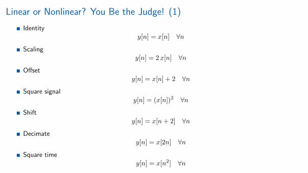
Linear or Nonlinear? You Be the Judge! (1)
Identityy[n] = x[n] ∀n
Scalingy[n] = 2x[n] ∀n
Offsety[n] = x[n] + 2 ∀n
Square signaly[n] = (x[n])2 ∀n
Shifty[n] = x[n+ 2] ∀n
Decimatey[n] = x[2n] ∀n
Square timey[n] = x[n2] ∀n
7

Linear or Nonlinear? You Be the Judge! (2)
Shift system (m ∈ Z fixed)y[n] = x[n−m] ∀n
Moving average (combines shift, sum, scale)
y[n] =1
2(x[n] + x[n− 1]) ∀n
Recursive averagey[n] = x[n] + α y[n− 1] ∀n
8

Matrix Multiplication and Linear Systems
Matrix multiplication (aka Linear Combination) is a fundamental signal processing system
Fact 1: Matrix multiplications are linear systems (easy to show at home, but do it!)
y = Hx
y[n] =∑m
[H]n,m x[m]
(Note: This formula applies for both infinite-length and finite-length signals)
Fact 2: All linear systems can be expressed as matrix multiplications
As a result, we will use the matrix viewpoint of linear systems extensively in the sequel
Try at home: Express all of the linear systems in the examples above in matrix form
9

Matrix Multiplication and Linear Systems in Pictures
Linear systemy = Hx
y[n] =∑m
[H]n,m x[m] =∑m
hn,m x[m]
where hn,m = [H]n,m represents the row-n, column-m entry of the matrix H
y H x
=
10

System Output as a Linear Combination of Columns
Linear systemy = Hx
y[n] =∑m
[H]n,m x[m] =∑m
hn,m x[m]
where hn,m = [H]n,m represents the row-n, column-m entry of the matrix H
y H x
= =
11

System Output as a Sequence of Inner Products
Linear systemy = Hx
y[n] =∑m
[H]n,m x[m] =∑m
hn,m x[m]
where hn,m = [H]n,m represents the row-n, column-m entry of the matrix H
y H x
=
12

Summary
Linear systems satisfy (1) scaling and (2) additivity
To show a system is linear, you have to prove it rigorously assuming arbitrary inputs (work!)
To show a system is nonlinear, you can just exhibit a counterexample (often easy!)
Linear systems ≡ matrix multiplication
• Justifies our emphasis on linear vector spaces and matrices
• The output signal y equals the linear combination of the columns of H weighted by the entries in x
• Alternatively, the output value y[n] equals the inner product between row n of H with x
13

Time-Invariant Systems

Time-Invariant Systems (Infinite-Length Signals)
A system H processing infinite-length signals is time-invariant (shift-invariant) ifa time shift of the input signal creates a corresponding time shift in the outputsignal
x[n] H y[n]
x[n− q] H y[n− q]
DE
FIN
ITIO
N
Intuition: A time-invariant system behaves the same no matter when the input is applied
A system that is not time-invariant is called time-varying
2

Example: Moving Average is Time-Invariant
x[n] H y[n] = 12 (x[n] + x[n− 1])
Letx′[n] = x[n− q], q ∈ Z
Let y′ denote the output when x′ is input (that is, y′ = H{x′})
Then
y′[n] =1
2(x′[n] + x′[n− 1]) =
1
2(x[n− q] + x[n− q − 1]) = y[n− q] X
3

Example: Decimation is Time-Varying
x[n] H y[n] = x[2n]
This system is time-varying; demonstrate with a counter-example
Letx′[n] = x[n− 1]
Let y′ denote the output when x′ is input (that is, y′ = H{x′})
Theny′[n] = x′[2n] = x[2n− 1] 6= x[2(n− 1)] = y[n− 1]
4

Time-Invariant or Time-Varying? You Be the Judge! (1)
Identityy[n] = x[n] ∀n
Scalingy[n] = 2x[n] ∀n
Offsety[n] = x[n] + 2 ∀n
Square signaly[n] = (x[n])2 ∀n
Shifty[n] = x[n+ 2] ∀n
Decimatey[n] = x[2n] ∀n
Square timey[n] = x[n2] ∀n
5

Time-Invariant or Time-Varying? You Be the Judge! (2)
Shift system (m ∈ Z fixed)y[n] = x[n−m] ∀n
Moving average (combines shift, sum, scale)
y[n] =1
2(x[n] + x[n− 1]) ∀n
Recursive averagey[n] = x[n] + α y[n− 1] ∀n
6

Time-Invariant Systems (Finite-Length Signals)
A system H processing length-N signals is time-invariant (shift-invariant) if acircular time shift of the input signal creates a corresponding circular time shift inthe output signal
x[n] H y[n]
x[(n− q)N ] H y[(n− q)N ]
DE
FIN
ITIO
N
Intuition: A time-invariant system behaves the same no matter when the input is applied
A system that is not time-invariant is called time-varying
7

Summary
Time-invariant systems behave the same no matter when the input is applied
Infinite-length signals: Invariance with respect to any integer time shift
Finite-length signals: Invariance with respect to a circular time shift
To show a system is time-invariant, you have to prove it rigorously assuming arbitrary inputs(work!)
To show a system is time-varying, you can just exhibit a counterexample (often easy!)
8

Linear Time-Invariant Systems

Linear Time Invariant (LTI) Systems
A system H is linear time-invariant (LTI) if it is both linear and time-invariant
DE
FIN
ITIO
N
LTI systems are the foundation of signal processing and the main subject of this course
2

LTI or Not? You Be the Judge! (1)
Identityy[n] = x[n] ∀n
Scalingy[n] = 2x[n] ∀n
Offsety[n] = x[n] + 2 ∀n
Square signaly[n] = (x[n])2 ∀n
Shifty[n] = x[n+ 2] ∀n
Decimatey[n] = x[2n] ∀n
Square timey[n] = x[n2] ∀n
3

LTI or Not? You Be the Judge! (2)
Shift system (m ∈ Z fixed)y[n] = x[n−m] ∀n
Moving average (combines shift, sum, scale)
y[n] =1
2(x[n] + x[n− 1]) ∀n
Recursive averagey[n] = x[n] + α y[n− 1] ∀n
4
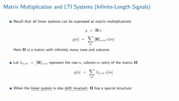
Matrix Multiplication and LTI Systems (Infinite-Length Signals)
Recall that all linear systems can be expressed as matrix multiplications
y = Hx
y[n] =∑m
[H]n,m x[m]
Here H is a matrix with infinitely many rows and columns
Let hn,m = [H]n,m represent the row-n, column-m entry of the matrix H
y[n] =∑m
hn,m x[m]
When the linear system is also shift invariant, H has a special structure
5

Matrix Structure of LTI Systems (Infinite-Length Signals)
Linear system for infinite-length signals can be expressed as
y[n] = H{x[n]} =
∞∑m=−∞
hn,m x[m], −∞ < n <∞
Enforcing time invariance implies that for all q ∈ Z
H{x[n− q]} =
∞∑m=−∞
hn,m x[m− q] = y[n− q]
Change of variables: n′ = n− q and m′ = m− q
H{x[n′]} =
∞∑m′=−∞
hn′+q,m′+q x[m′] = y[n′]
Comparing first and third equations, we see that for an LTI system
hn,m = hn+q,m+q ∀ q ∈ Z
6

LTI Systems are Toeplitz Matrices (Infinite-Length Signals) (1)
For an LTI system with infinite-length signals
hn,m = hn+q,m+q ∀ q ∈ Z
H =
......
...· · · h−1,−1 h−1,0 h−1,1 · · ·· · · h0,−1 h0,0 h0,1 · · ·· · · h1,−1 h1,0 h1,1 · · ·
......
...
=
......
...· · · h0,0 h−1,0 h−2,0 · · ·· · · h1,0 h0,0 h−1,0 · · ·· · · h2,0 h1,0 h0,0 · · ·
......
...
Entries on the matrix diagonals are the same – Toeplitz matrix
7

LTI Systems are Toeplitz Matrices (Infinite-Length Signals) (2)
All of the entries in a Toeplitz matrix can be expressed in terms of the entries of the
• 0-th column: h[n] = hn,0
• Time-reversed 0-th row: h[m] = h0,−m
H =
......
...· · · h0,0 h−1,0 h−1,1 · · ·· · · h1,0 h0,0 h−1,0 · · ·· · · h2,0 h1,0 h0,0 · · ·
......
...
=
......
...· · · h[0] h[−1] h[−2] · · ·· · · h[1] h[0] h[−1] · · ·· · · h[2] h[1] h[0] · · ·
......
...
Row-n, column-m entry of the matrix [H]n,m = hn,m = h[n−m]
8

LTI Systems are Toeplitz Matrices (Infinite-Length Signals) (3)
All of the entries in a Toeplitz matrix can be expressed in terms of the entries of the
• 0-th column: h[n] = hn,0 (this is an infinite-length signal/column vector; call it h)
• Time-reversed 0-th row: h[m] = h0,−m
Example: Snippet ofa Toeplitz matrix
[H]n,m = hn,m
= h[n−m]
Note the diagonals!
H = h =
9

Matrix Structure of LTI Systems (Finite-Length Signals)
Linear system for signals of length N can be expressed as
y[n] = H{x[n]} =
N−1∑m=0
hn,m x[m], 0 ≤ n ≤ N − 1
Enforcing time invariance implies that for all q ∈ Z
H{x[(n− q)N ]} =N−1∑m=0
hn,m x[(m− q)N ] = y[(n− q)N ]
Change of variables: n′ = n− q and m′ = m− q
H{x[(n′)N ]} =
M−1−q∑m′=−q
h(n′+q)N ,(m′+q)N x[(m′)N ] = y[(n′)N ]
Comparing first and third equations, we see that for an LTI system
hn,m = h(n+q)N ,(m+q)N ∀ q ∈ Z
10

LTI Systems are Circulent Matrices (Finite-Length Signals) (1)
For an LTI system with length-N signals
hn,m = h(n+q)N ,(m+q)N ∀ q ∈ Z
h0,0 h0,1 h0,2 · · · h0,N−1h1,0 h1,1 h1,2 · · · h1,N−1h2,0 h2,1 h2,2 · · · h2,N−1
......
......
hN−1,0 hN−1,1 hN−1,2 · · · hN−1,N−1
=
h0,0 hN−1,0 hN−2,0 · · · h1,0h1,0 h0,0 hN−1,0 · · · h2,0h2,0 h1,0 h0,0 · · · h3,0
......
......
hN−1,0 hN−2,0 hN−3,0 · · · h0,0
Entries on the matrix diagonals are the same + circular wraparound – circulent matrix
11

LTI Systems are Circulent Matrices (Finite-Length Signals) (2)
All of the entries in a circulent matrix can be expressed in terms of the entries of the
• 0-th column: h[n] = hn,0
• Circularly time-reversed 0-th row: h[m] = h0,(−m)N
h0,0 hN−1,0 hN−2,0 · · · h1,0h1,0 h0,0 hN−1,0 · · · h2,0h2,0 h1,0 h0,0 · · · h3,0
......
......
hN−1,0 hN−2,0 hN−3,0 · · · h0,0
=
h[0] h[N − 1] h[N − 2] · · · h[1]
h[1] h[0] h[N − 1] · · · h[2]
h[2] h[1] h[0] · · · h[3]...
......
...h[N − 1] h[N − 2] h[N − 3] · · · h[0]
Row-n, column-m entry of the matrix [H]n,m = hn,m = h[(n−m)N ]
12

LTI Systems are Circulent Matrices (Finite-Length Signals) (3)
All of the entries in a circulent matrix can be expressed in terms of the entries of the
• 0-th column: h[n] = hn,0 (this is a signal/column vector; call it h)
• Circularly time-reversed 0-th row: h[m] = h0,−m
Example: Circulent matrix
[H]n,m = hn,m
= h[(n−m)N ]
Note the diagonalsand circulent shifts!
H = h =
13

Summary
LTI = Linear + Time-Invariant
Fundamental signal processing system (and our focus for the rest of the course)
Infinite-length signals: System = Toeplitz matrix H
• [H]n,m = hn,m = h[n−m]
Finite-length signals: System = Circulent matrix H
• [H]n,m = hn,m = h[(n−m)N ]
14

Impulse Response

Recall: LTI Systems are Toeplitz Matrices (Infinite-Length Signals)
x H y
LTI system = multiplication by infinitely large Toeplitz matrix H: y = Hx
All of the entries in H can be obtained from the
• 0-th column: h[n] = hn,0 (this is a signal/column vector; call it h)
• Time-reversed 0-th row: h[m] = h0,−m
[H]n,m = hn,m
= h[n−m]
Columns/rows of H areshifted versions of the0-th column/row
h = H =
2
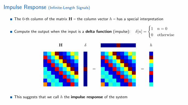
Impulse Response (Infinite-Length Signals)
The 0-th column of the matrix H – the column vector h – has a special interpretation
Compute the output when the input is a delta function (impulse): δ[n] =
{1 n = 0
0 otherwise
H δ h
= =
This suggests that we call h the impulse response of the system
3

Impulse Response from Formulas (Infinite-Length Signals)
General formula for LTI matrix multiplication
y[n] =
∞∑m=−∞
h[n−m]x[m]
Let the input x[n] = δ[n] and compute
∞∑m=−∞
h[n−m] δ[m] = h[n] X
δ H h
The impulse response characterizes an LTI system(that is, carries all of the information contained in the matrix H)
x h y
4

Example: Impulse Response of the Scaling System
x H y
Consider system for infinite-length signals;finite-length signal case is similar
−8 −6 −4 −2 0 2 4 6 80
1
2
h[n ] = 2 δ [n ]
n
Scaling system: y[n] = H{x[n]} = 2x[n]
Impulse response: h[n] = H{δ[n]} = 2 δ[n]
Toeplitz system matrix:
[H]n,m = h[n−m] = 2 δ[n−m]H =
5

Example: Impulse Response of the Shift System
x H y
Consider system for infinite-length signals;finite-length signal case uses circular shift
−8 −6 −4 −2 0 2 4 6 80
0.5
1
h[n ] = δ [n − 2]
n
Scaling system: y[n] = H{x[n]} = x[n− 2]
Impulse response: h[n] = H{δ[n]} = δ[n− 2]
Toeplitz system matrix:
[H]n,m = h[n−m] = δ[n−m− 2]H =
6

Example: Impulse Response of the Moving Average System
x H y
Consider system for infinite-length signals;finite-length signal case is similar
−8 −6 −4 −2 0 2 4 6 80
0.5
h[n ] = 12 (δ [n ] + δ [n − 1])
n
Moving average system: y[n] = H{x[n]} = 12 (x[n] + x[n− 1])
Impulse response: h[n] = H{δ[n]} = 12 (δ[n] + δ[n− 1])
Toeplitz system matrix:
[H]n,m = h[n−m] = 12 (δ[n−m] + δ[n−m− 1])
H =
7

Example: Impulse Response of the Recursive Average System
x H y
Consider system for infinite-length signals;finite-length signal case is similar
−8 −6 −4 −2 0 2 4 6 80
0.5
1
h[n ] = αn u[n ], α = 0.8
n
Recursive average system: y[n] = H{x[n]} = x[n] + α y[n− 1]
Impulse response: h[n] = H{δ[n]} = αn u[n]
Toeplitz system matrix:
[H]n,m = h[n−m] = αn−m u[n−m]H =
8

Recall: LTI Systems are Circulent Matrices (Finite-Length Signals)
x H y
LTI system = multiplication by N ×N circulent matrix H: y = Hx
All of the entries in H can be obtained from the
• 0-th column: h[n] = hn,0 (this is a signal/column vector; call it h)
• Time-reversed 0-th row: h[m] = h0,(−m)N
[H]n,m = hn,m
= h[(n−m)N ]
Columns/rows of H arecircularly shifted versionsof the 0-th column/row
h = H =
9

Impulse Response (Finite-Length Signals)
The 0-th column of the matrix H – the column vector h – has a special interpretation
Compute the output when the input is a delta function (impulse): δ[n] =
{1 n = 0
0 otherwise
H δ h
= =
This suggests that we call h the impulse response of the system
10

Impulse Response from Formulas (Finite-Length Signals)
General formula for LTI matrix multiplication
y[n] =
N−1∑m=0
h[(n−m)N ]x[m]
Let the input x[n] = δ[n] and compute
N−1∑m=0
h[(n−m)N ] δ[m] = h[n] X
δ H h
The impulse response characterizes an LTI system(that is, carries all of the information contained in the matrix H)
x h y
11

Summary
LTI system = multiplication by infinite-sized Toeplitz or N ×N circulent matrix H: y = Hx
The impulse response h of an LTI system = the response to an impulse δ
• The impulse response is the 0-th column of the matrix H• The impulse response characterizes an LTI system
x h y
Formula for the output signal y in terms of the input signal x and the impulse response h
• Infinite-length signals
y[n] =∞∑
m=−∞
h[n−m]x[m], −∞ < n <∞
• Length-N signals
y[n] =
N−1∑m=0
h[(n−m)N ]x[m], 0 ≤ n ≤ N − 1
12

Convolution, Part 1(Infinite-Length Signals)

Three Ways to Compute the Output of an LTI System Given the Input
x H y
1 If H is defined in terms of a formula or algorithm, apply the input x and compute y[n] at eachtime point n ∈ Z
• This is how systems are usually applied in computer code and hardware
2 Find the impulse response h (by inputting x[n] = δ[n]), form the Toeplitz system matrix H,and multiply by the (infinite-length) input signal vector x to obtain y = Hx
• This is not usually practical but is useful for conceptual purposes
3 Find the impulse response h and apply the formula for matrix/vector product for each n ∈ Z
y[n] =
∞∑m=−∞
h[n−m]x[m] = x[n] ∗ h[n]
• This is called convolution and is both conceptually and practically useful (Matlab command: conv)
2

Convolution as a Sequence of Inner Products
x h y
Convolution formula
y[n] = x[n] ∗ h[n] =∞∑
m=−∞h[n−m]x[m]
To compute the entry y[n] in the output vector y:
1 Time reverse the impulse response vector h and
shift it n time steps to the right (delay)
2 Compute the inner product between the shifted
impulse response and the input vector x
Repeat for every n
y H x
=
3

A Seven-Step Program for Computing Convolution By Hand
y[n] = x[n] ∗ h[n] =
∞∑m=−∞
h[n−m]x[m]
Step 1: Decide which of x or h you will flip and shift; you have a choice since x ∗ h = h ∗ x
Step 2: Plot x[m] as a function of m
Step 3: Plot the time-reversed impulse response h[−m]
Step 4: To compute y at the time point n, plot the time-reversed impulse response after it hasbeen shifted to the right (delayed) by n time units: h[−(m− n)] = h[n−m]
Step 5: y[n] = the inner product between the signals x[m] and h[n−m]
(Note: for complex signals, do not complex conjugate the second signal in the inner product)
Step 6: Repeat for all n of interest (potentially all n ∈ Z)
Step 7: Plot y[n] and perform a reality check to make sure your answer seems reasonable
4

First Convolution Example (1)
y[n] = x[n] ∗ h[n] =
∞∑m=−∞
h[n−m]x[m]
Convolve a unit pulse with itself
−4 −2 0 2 4 60
0.5
1
x[n ]
n
5

First Convolution Example (2)
y[n] = x[n] ∗ h[n] =
∞∑m=−∞
h[n−m]x[m]
−6 −4 −2 0 2 4 60
0.5
1
x[m]
m−6 −4 −2 0 2 4 60
0.5
1
h[−m]
m
6

Convolution, Part 2(Infinite-Length Signals)

A Seven-Step Program for Computing Convolution By Hand
y[n] = x[n] ∗ h[n] =
∞∑m=−∞
h[n−m]x[m]
Step 1: Decide which of x or h you will flip and shift; you have a choice since x ∗ h = h ∗ x
Step 2: Plot x[m] as a function of m
Step 3: Plot the time-reversed impulse response h[−m]
Step 4: To compute y at the time point n, plot the time-reversed impulse response after it hasbeen shifted to the right (delayed) by n time units: h[−(m− n)] = h[n−m]
Step 5: y[n] = the inner product between the signals x[m] and h[n−m]
(Note: for complex signals, do not complex conjugate the second signal in the inner product)
Step 6: Repeat for all n of interest (potentially all n ∈ Z)
Step 7: Plot y[n] and perform a reality check to make sure your answer seems reasonable
2

Second Convolution Example (1)
Recall the recursive average system
y[n] = x[n] +1
2y[n− 1]
and its impulse response h[n] =(12
)nu[n]
−8 −6 −4 −2 0 2 4 6 80
0.5
1
h[n ]
n
Compute the output y when the input is a unit step x[n] = u[n]
−8 −6 −4 −2 0 2 4 6 80
0.5
1
x[n ]
n
3

Second Convolution Example (2)
y[n] = h[n] ∗ x[n] =
∞∑m=−∞
h[m]x[n−m]
−8 −6 −4 −2 0 2 4 6 80
0.5
1
h[m]
m−8 −6 −4 −2 0 2 4 6 80
0.5
1
x[−m]
m
Recall the super useful formula for the finite geometric series
N2∑k=N1
ak =aN1 − aN2+1
1− a, N1 ≤ N2
4

Second Convolution Example (3)
y[n] = h[n] ∗ x[n] =
∞∑m=−∞
h[m]x[n−m]
−8 −6 −4 −2 0 2 4 6 80
0.5
1
h[m]
m−8 −6 −4 −2 0 2 4 6 80
0.5
1
x[−m]
m
5

Summary
Convolution formula for the output y of an LTI system given the input x and the impulseresponse h (infinite-length signals)
y[n] = x[n] ∗ h[n] =
∞∑m=−∞
h[n−m]x[m]
Convolution is a sequence of inner products between the signal and the shifted, time-reversedimpulse response
Seven-step program for computing convolution by hand
Check your work and compute large convolutions using Matlab command conv
Practice makes perfect!
6

Circular Convolution(Finite-Length Signals)
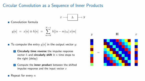
Circular Convolution as a Sequence of Inner Products
x h y
Convolution formula
y[n] = x[n]~ h[n] =
N−1∑m=0
h[(n−m)N ]x[m]
To compute the entry y[n] in the output vector y:
1 Circularly time reverse the impulse response
vector h and circularly shift it n time steps to
the right (delay)
2 Compute the inner product between the shifted
impulse response and the input vector x
Repeat for every n
y H x
=
2

A Seven-Step Program for Computing Circular Convolution By Hand
y[n] = x[n]~ h[n] =
N−1∑m=0
h[(n−m)N ]x[m]
Step 1: Decide which of x or h you will flip and shift; you have a choice since x ∗ h = h ∗ x
Step 2: Plot x[m] as a function of m on a clock with N “hours”
Step 3: Plot the circularly time-reversed impulse response h[(−m)N ] on a clock with N “hours”
Step 4: To compute y at the time point n, plot the time-reversed impulse response after it hasbeen shifted counter-clockwise (delayed) by n time units: h[(−(m− n))N ] = h[(n−m)N ]
Step 5: y[n] = the inner product between the signals x[m] and h[(n−m)N ]
(Note: for complex signals, do not complex conjugate the second signal in the inner product)
Step 6: Repeat for all n = 0, 1, . . . , N − 1
Step 7: Plot y[n] and perform a reality check to make sure your answer seems reasonable
3
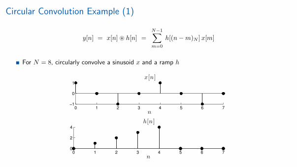
Circular Convolution Example (1)
y[n] = x[n]~ h[n] =
N−1∑m=0
h[(n−m)N ]x[m]
For N = 8, circularly convolve a sinusoid x and a ramp h
0 1 2 3 4 5 6 7−1
0
1
x[n ]
n
0 1 2 3 4 5 6 70
2
4
h[n ]
n
4

Circular Convolution Example (2)
y[n] = x[n]~ h[n] =
N−1∑m=0
h[(n−m)N ]x[m]
5

Summary
Circular convolution formula for the output y of an LTI system given the input x and theimpulse response h (length-N signals)
y[n] = x[n]~ h[n] =
N−1∑m=0
h[(n−m)N ]x[m]
Circular convolution is a sequence of inner products between the signal and the circularly shifted,time-reversed impulse response
Seven-step program for computing circular convolution by hand
Check your work and compute large circular convolutions using Matlab command cconv
Practice makes perfect!
6

Properties of Convolution

Properties of Convolution
x h y
Input signal x, LTI system impulse response h, and output signal y are related by the convolution
• Infinite-length signals
y[n] = x[n] ∗ h[n] =
∞∑m=−∞
h[n−m]x[m], −∞ < n <∞
• Length-N signals
y[n] = x[n]~ h[n] =
N−1∑m=0
h[(n−m)N ]x[m], 0 ≤ n ≤ N − 1
Thanks to the Toeplitz/circulent structure of LTI systems, convolution has very special properties
We will emphasize infinite-length convolution, but similar arguments hold for circular convolutionexcept where noted
2
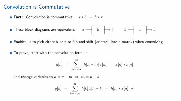
Convolution is Commutative
Fact: Convolution is commutative: x ∗ h = h ∗ x
These block diagrams are equivalent: x h y h x y
Enables us to pick either h or x to flip and shift (or stack into a matrix) when convolving
To prove, start with the convolution formula
y[n] =
∞∑m=−∞
h[n−m]x[m] = x[n] ∗ h[n]
and change variables to k = n−m ⇒ m = n− k
y[n] =
∞∑k=−∞
h[k]x[n− k] = h[n] ∗ x[n] X
3

Cascade Connection of LTI Systems
Impulse response of the cascade (aka series connection) of two LTI systems: y = H1H2 x
x h1 h2 y
x h1 ∗ h2 y
Interpretation: The product of two Toeplitz/circulent matrices is a Toeplitz/circulent matrix
Easy proof by picture; find impulse response the old school way
δ h1 h1 h2 h1 ∗ h2
4

Parallel Connection of LTI Systems
Impulse response of the parallel connection of two LTI systems y = (H1 +H2)x
h1
h2
+ ≡ h1 + h2
Proof is an easy application of the linearity of an LTI system
5

Example: Impulse Response of a Complicated Connection of LTI Systems
Compute the overall effective impulse response of the following system
x h y
6
Causal Systems
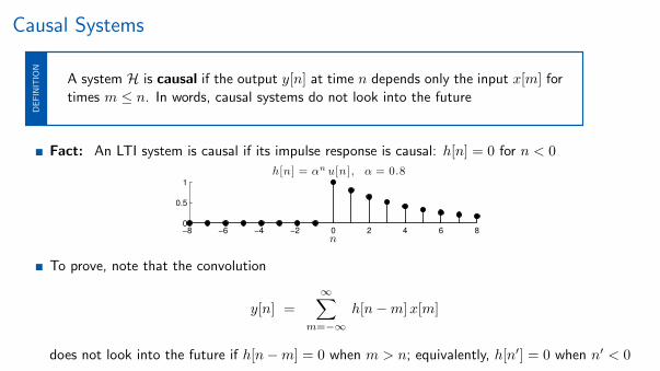
A system H is causal if the output y[n] at time n depends only the input x[m] fortimes m ≤ n. In words, causal systems do not look into the future
DE
FIN
ITIO
N
Fact: An LTI system is causal if its impulse response is causal: h[n] = 0 for n < 0
−8 −6 −4 −2 0 2 4 6 80
0.5
1
h[n ] = αn u[n ], α = 0.8
n
To prove, note that the convolution
y[n] =
∞∑m=−∞
h[n−m]x[m]
does not look into the future if h[n−m] = 0 when m > n; equivalently, h[n′] = 0 when n′ < 0
7

Causal System Matrix
Fact: An LTI system is causal if its impulse response is causal: h[n] = 0 for n < 0
−8 −6 −4 −2 0 2 4 6 80
0.5
1
h[n ] = αn u[n ], α = 0.8
n
Toeplitz system matrix is lower triangular
8

Duration of Convolution
The signal x has support interval [N1, N2], N1 ≤ N2, if x[n] = 0 for all n < N1
and n > N2. The duration Dx of x equals N2 −N1 + 1
DE
FIN
ITIO
N
Example: A signal with support interval [−5, 5] and duration 11 samples
−15 −10 −5 0 5 10 15−2
0
2
x[n ]
n
Fact: If x has duration Dx samples and h has duration Dh samples, then the convolutiony = x ∗ h has duration at most Dx +Dh − 1 samples (proof by picture is simple)
9

Duration of Impulse Response – FIR
An LTI system has a finite impulse response (FIR) if the duration of its impulseresponse h is finite
DE
FIN
ITIO
N
Example: Moving average system y[n] = H{x[n]} = 12 (x[n] + x[n− 1])
−8 −6 −4 −2 0 2 4 6 80
0.5
h[n ] = 12 (δ [n ] + δ [n − 1])
n
10

Duration of Impulse Response – IIR
An LTI system has an infinite impulse response (IIR) if the duration of its impulseresponse h is infinite
DE
FIN
ITIO
N
Example: Recursive average system y[n] = H{x[n]} = x[n] + α y[n− 1]
−8 −6 −4 −2 0 2 4 6 80
0.5
1
h[n ] = αn u[n ], α = 0.8
n
Note: Obviously the FIR/IIR distinction applies only to infinite-length signals
11

Implementing Infinite-Length Convolution with Circular Convolution
Consider two infinite-length signals: x has duration Dx samples and h has duration Dh samples,Dx, Dh <∞
Recall that their infinite-length convolution y = x ∗ h has duration at most Dx +Dh − 1 samples
Armed with this fact, we can implement infinite-length convolution using circular convolution
1 Extract the Dx-sample support interval of x and zero pad so that the resulting signal x′ is of
length Dx +Dh − 1
2 Perform the same operations on h to obtain h′
3 Circularly convolve x′ ~ h′ to obtain y′
Fact: The values of the signal y′ will coincide with those of the infinite-length convolutiony = x ∗ h within its support interval
How does it work? The zero padding effectively converts circular shifts (finite-length signals) intoregular shifts (infinite-length signals) (Easy to try out in Matlab!)
12

Summary
Convolution has very special and beautiful properties
Convolution is commutative
Convolutions (LTI systems) can be connected in cascade and parallel
An LTI system is causal if its impulse response is causal
LTI systems are either FIR or IIR
Can implement infinite-length convolution using circular convolution when the signals have finiteduration (important later for “fast convolution” using the FFT)
13

Convolution Examplesin Matlab

Convolution in Matlab
You can build your intuition and solve real-world problems using Matlab’s convolution functions
Matlab’s conv command implements infinite-length convolution
y[n] = x[n] ∗ h[n] =
∞∑m=−∞
h[n−m]x[m]
by implicitly infinitely zero-padding the signal vectors; signal lengths need not be the same
Matlab’s cconv command implements length-N circular convolution
y[n] = x[n]~ h[n] =
N−1∑m=0
h[(n−m)N ]x[m]
2

Stable Systems

Stable Systems (1)
With a stable system, a “well-behaved” input always produces a “well-behaved” output
“well-behaved” x h “well-behaved” y
Stability is essential to ensuring the proper and safe operation of myriad systems
• Steering systems• Braking systems• Robotic navigation• Modern aircraft• International Space Station• Internet IP packet communication (TCP) . . .
2

Stable Systems (2)
With a stable system, a “well-behaved” input always produces a “well-behaved” output
“well-behaved” x h “well-behaved” y
Example: Recall the recursive average system y[n] = H{x[n]} = x[n] + α y[n− 1]
Consider a step function input x[n] = u[n]
−4 −2 0 2 4 6 80
0.5
1
x[n ] = u[n ]
n
−4 −2 0 2 4 6 80
1
2
y [n ], with α = 12
n−4 −2 0 2 4 6 8
0
50
100
y [n ], with α = 32
n
3

Well-Behaved Signals
With a stable system, a “well-behaved” input always produces a “well-behaved” output
“well-behaved” x h “well-behaved” y
How to measure how “well-behaved” a signal is? Different measures give different notions ofstability
One reasonable measure: A signal x is well behaved if it is bounded (recall that sup is like max)
‖x‖∞ = supn|x[n]| < ∞
4

Bounded-Input Bounded-Output (BIBO) Stability
5

BIBO Stability (1)
An LTI system is bounded-input bounded-output (BIBO) stable if a boundedinput x always produces a bounded output y
bounded x h bounded yDE
FIN
ITIO
N
Bounded input and output means ‖x‖∞ <∞ and ‖y‖∞ <∞,or that there exist constants A,C <∞ such that |x[n]| < A and |y[n]| < C for all n
−15 −10 −5 0 5 10 15−1
0
1
x[n]
n
h
−15 −10 −5 0 5 10 15
−2
0
2
y[n]
n
6

BIBO Stability (2)
An LTI system is bounded-input bounded-output (BIBO) stable if a boundedinput x always produces a bounded output y
bounded x h bounded yDE
FIN
ITIO
N
Bounded input and output means ‖x‖∞ <∞ and ‖y‖∞ <∞
−15 −10 −5 0 5 10 15−1
0
1
x[n]
n
h
−15 −10 −5 0 5 10 15
−2
0
2
y[n]
n
Fact: An LTI system with impulse response h is BIBO stable if and only if
‖h‖1 =
∞∑n=−∞
|h[n| < ∞
7

BIBO Stability – Sufficient Condition
Prove that if ‖h‖1 <∞ then the system is BIBO stable – for any input ‖x‖∞ <∞ the output‖y‖∞ <∞
Recall that ‖x‖∞ <∞ means there exist a constant A such that |x[n]| < A <∞ for all n
Let ‖h‖1 =∑∞n=−∞ |h[n]| = B <∞
Compute a bound on |y[n]| using the convolution of x and h and the bounds A and B
|y[n]| =
∣∣∣∣∣∞∑
m=−∞h[n−m]x[m]
∣∣∣∣∣ <
∞∑m=−∞
|h[n−m]| |x[m]|
<
∞∑m=−∞
|h[n−m]|A = A∞∑
k=−∞
|h[k]| = AB = C < ∞
Since |y[n]| < C <∞ for all n, ‖y‖∞ <∞ X
8

BIBO Stability – Necessary Condition (1)
Prove that if ‖h‖1 =∞ then the system is not BIBO stable – there exists an input ‖x‖∞ <∞such that the output ‖y‖∞ =∞
• Assume that x and h are real-valued; the proof for complex-valued signals is nearly identical
Given an impulse response h with ‖h‖1 =∞ (assume complex-valued), form the tricky specialsignal x[n] = sgn(h[−n])
• x[n] is the ± sign of the time-reversed impulse response h[−n]• Note that x is bounded: |x[n]| ≤ 1 for all n
−15 −10 −5 0 5 10 15−5
0
5
h[n]
n−15 −10 −5 0 5 10 15
−5
0
5
h[−n]
n
−15 −10 −5 0 5 10 15−1
0
1
x[n]
n
9

BIBO Stability – Necessary Condition (2)
We are proving that that if ‖h‖1 =∞ then the system is not BIBO stable – there exists an input‖x‖∞ <∞ such that the output ‖y‖∞ =∞
Armed with the tricky special signal x, compute the output y[n] at the time point n = 0
y[0] =
∞∑m=−∞
h[0−m]x[m] =
∞∑m=−∞
h[−m] sgn(h[−m])
=
∞∑m=−∞
|h[−m]| =
∞∑k=−∞
|h[k]| = ∞
So, even though x was bounded, y is not bounded; so system is not BIBO stable
10

BIBO System Examples (1)
Absolute summability of the impulse response h determines whether an LTI systems is BIBOstable or not
Example: h[n] =
{1n n ≥ 1
0 otherwise−5 0 5 10 15 20 250
0.5
1
h[n ]
n
‖h‖1 =∑∞n=1
∣∣ 1n
∣∣ =∞ ⇒ not BIBO
Example: h[n] =
{1n2 n ≥ 1
0 otherwise−5 0 5 10 15 20 250
0.5
1
h[n ]
n
‖h‖1 =∑∞n=1
∣∣ 1n2
∣∣ = π2
6 ⇒ BIBO
Example: h FIR ⇒ BIBO
−5 0 5 10 15 20 25−2
−1
0
1
h[n ] (FIR)
n
11

BIBO System Examples (2)
Example: Recall the recursive average system y[n] = H{x[n]} = x[n] + α y[n− 1]
Impulse response: h[n] = αn u[n]
For |α| < 1
‖h‖1 =∑∞n=0 |α|n = 1
1−|α| <∞ ⇒ BIBO
−6 −4 −2 0 2 4 6 80
0.5
1
h[n ]
n
For |α| > 1
‖h‖1 =∑∞n=0 |α|n =∞ ⇒ not BIBO
−6 −4 −2 0 2 4 6 80
2
4
h[n ]
n
12

Summary
Signal processing applications typically dictate that the system be stable, meaning that“well-behaved inputs” produce “well-behaved outputs”
Measure “well-behavedness” of a signal using the ∞-norm (bounded signal)
BIBO stability: bounded inputs always produce bounded outputs iff the impulse response h issuch that ‖h‖1 <∞
When a system is not BIBO stable, all hope is not lost; unstable systems can often by stabilizedusing feedback (more on this later)
13

Acknowledgements
c© 2014 Richard Baraniuk, All Rights Reserved
2