systemate systemate 20002000 - gledhill spares · design, installation and servicing instructions a...
TRANSCRIPT

DESIGN, INSTALLATION AND SERVICING INSTRUCTIONS
A SEALED CENTRAL HEATINGAND MAINS PRESSURE HOT WATER SUPPLY
SYSTEM INCORPORATING A THERMAL STORE
ALL MODELS COMPLY WITH THE WATER HEATER MANUFACTURERS
SPECIFICATION FOR HOT WATER ONLY THERMAL STORES
SYSTEMATE 2000SYSTEMATE 2000
TM
benchmarkThe code of practice for the installation,
commissioning & servicing of central heating systems
Gas Council Approved Reference Numbers
SysteMate 125 97-317-26SysteMate 145 97-317-27SysteMate 185 97-317-28SysteMate 210 97-317-29SysteMate 225 97-317-30

Page 2
CONTENTS
Section Page
1.0 DESIGN
1.1 Introduction 3 1.2 Technical Data 5
1.3 System Details 10 2.0 INSTALLATION
2.1 Site Requirements 16
2.2 Installation 17
2.3 Commissioning 25
3.0 SERVICING
3.1 Annual Servicing 29
3.2 Changing Components 29 3.3 Short Parts List 30 3.4 Fault Finding 32
Appendix A 34 Appendix B 35
Appendix C 38
Appendix D 39
Appendix E 40
Terms & Conditions 38
ISSUE 10 : 06-08
The Gledhill SysteMate 2000 range is a WBS listed product and complies with the WMA Specifi cation for hot water only thermal storage products. The principle was developed in conjunction with British Gas. This product is manufactured under an ISO 9001: 2000 Quality System audited by BSI.
Patents Pending
The Gledhill Group’s fi rst priority is to give a high quality service to our customers.
Quality is built into every Gledhill product and we hope you get satisfactory service from Gledhill.
If not please let us know.
As part of the industry wide “Benchmark” Initiative all Gledhill SysteMates now include a Benchmark Installation, Commissioning and Service Record Log Book. Please read carefully and complete all sections relevant to the appliance installation. The details of the Log Book will be required in the event of any warranty work being required. There is also a section to be completed after each regular service visit. The completed Log Book and these instructions should be left in the pocket provided on the back of the front panel.
TM
benchmarkThe code of practice for the installation,
commissioning & servicing of central heating systems

Page 3
SYST
EMA
TE 2
00
0
1.0 DESIGN
1.1 INTRODUCTION
T h e s e i n s t r u c t i o n s s h o u l d b e r e a d i n conjunction with the Installation and Servicing Instructions issued by the manufacturers of the heat source e.g. the boiler used.
Any water distribution and central heating installation must comply with the relevant recommendations of the current version of the Regulations and British Standards listed below:-
Gas Safety RegulationsBuilding RegulationsI.E.E. Requirements for Electrical InstallationsWater Regulations
British StandardsBS6798, BS5449, BS5546, BS5440:1, BS5440:2, CP331:3, BS6700, BS5258, BS7593 and BS7671.
A competent person as stated in the Gas Safety Regulations must install the SysteMate 2000 heating system. The manufacturer’s notes must not be taken as overriding statutory obligations.
The SysteMate 2000 is only suitable for use with a sealed primary, i.e. central heating, system.
The SysteMate 2000 is not covered by section G3 of the current Building Regulations and is therefore not notifi able to Building Control.
The information in this manual is provided to assist generally in the selection of equipment. The responsibility for the selection and specifi cation of the equipment must however remain that of the customer and any Designers or Consultants concerned with the design and installation.
Please Note: We do not therefore accept any responsibility for matters of design, selection or specifi cation or for the effectiveness of an installation containing one of our products unless we have been specifi cally requested to do so.
All goods are sold subject to our Conditions of Sale, which are set out at the rear of this manual.
In the interest of continuously improving the SysteMate range, Gledhill Water Storage Ltd reserve the right to modify the product without notice, and in these circumstances this document, which is accurate at the time of printing, should be disregarded. It will however be updated as soon as possible after the change has occurred.

Page 4
The SysteMate 2000 shown schematically above is designed to provide sealed system space heating and mains pressure hot water at high fl ow rates when coupled to any remotely sited, condensing or non condensing, boiler suitable for sealed heating systems, as long as they comply with the recommendations contained in the rest of this manual.
The SysteMate 2000 is an indirectly heated hot water only thermal store and is supplied with the factory fi tted controls and equipment shown in Section 1.2 Technical Data.
The indirect heat exchanger is highly effi cient and designed to provide extremely quick hot water recovery as well as back-up space heating when using ‘Switch’.
For details of how to produce SAP ratings calculations contact Gledhill Technical Department.
Because the F & E cistern is only used to fi ll the thermal store the standard appliance is supplied as a manual fi ll model, i,e, without a ballvalve and overfl ow, which makes it particularly suitable for use in fl ats/apartments. A ballvalve and overfl ow fi tting can be supplied as an optional extra if required.
1.0 DESIGN
Description
1.1 INTRODUCTION
An important feature of this product is that hot water can be supplied directly from the mains at conventional fl ow rates without the need for temperature and pressure relief safety valves or expansion vessels. This is achieved by passing the mains water through a plate heat exchanger. The outlet temperature of the domestic hot water is maintained by a printed circuit board, which controls the speed of the pump circulating the primary water from the store through the plate heat exchanger.
To comply with the Benchmark Guidance Note for Water Treatment in heating and hot water systems the installer should check the hardness levels of the water supply and if necessary fi t an in-line scale inhibitor/reducer to provide protection to the whole of the domestic water system.
If scale should ever become a problem the plate heat exchanger is easily isolated and quickly replaced with a service exchange unit which can be obtained at a nominal cost from Gledhill. For further details see Section 1.3 Hot and cold Water Systems.
The whole system is controlled by a special electronic control p.c.b. complete with programmer to which an external room thermostat can be easily connected.
The pcb also incorporates the facility to operate the heating pump for a few seconds every few days when the heating is not being used, to reduce the likelihood of the pumps sticking as well as providing a boiler pump overrun facility.
Any sealed system automatic boiler designed to operate on an 820C fl ow and a 710C return up to a maximum of 35kW can be linked to any suitable model of SysteMate 2000 and the deciding factor is the space heating and the hot water requirements of a dwelling. See Section 1.2 Technical Data for further details.
The SysteMate 2000 is available with the option of ‘Switch’ which will provide a 9kW electrical emergency backup in case of failure of the main heat source. See section 1.3 System Details for further information.
There is no facility available to incorporate a standard 3kW immersion heater for back up hot water only.
Gledhill are part of the ‘Benchmark’ scheme and a separate commissioning/service log book is included with the product.
RemoteF&E cistern
Cold feed
Hot
Cold
Open Vent
Boiler
ExpansionVessel
Pressure relief (safety) valve
Components fitted within the appliance case
Automatic bypass valve
Filling loop
Pressure gauge

Page 5
SYST
EMA
TE 2
00
0
ledoM 521MS 541MS 581MS 012MS 522MS
)ytpme(thgieW gk56 gk86 gk27 gk98 gk101
)lluf(thgieW gk081 gk391 gk222 gk952 gk192
pmuPWHD 05/51sofdnurG 05/51sofdnurG 05/51sofdnurG 05/51sofdnurG 05/51sofdnurG
pmuPgnitaeH 05/51sofdnurG 05/51sofdnurG 05/51sofdnurG 06/51sofdnurG 06/51sofdnurG
pmuPrelioB 05/51sofdnurG 05/51sofdnurG 05/51sofdnurG 06/51sofdnurG 06/51sofdnurG
epipgnitaeh/yramirPsnoitcennoc
mm22 mm22 mm22 mm82 mm82
epipWHD&WCMsnoitcennoc
mm22 mm22 mm22 mm22 mm22
noisnapxe/deefdloCnoitcennoc
mm51 mm51 mm51 mm51 mm51
tnevnepoytefaSnoitcennoc
mm22 mm22 mm22 mm22 mm22
snoitcennocyramirPesuremmusrof(
)liarlewotmoorhtabmm51 mm51 mm51 mm51 mm51
noitcennoCniarD ''½R ''½R ''½R ''½R ''½R
daeHmumixaMerotSlamrehT
sretem01 sretem01 sretem01 sretem01 sretem01
erusserpmumixaMtiucricgnitaeh
rab3 rab3 rab3 rab3 rab3
erusserpmumixaMretawcitsemod
rab5 rab5 rab5 rab5 rab5
liocyramirpfoemuloV)sertil(
0.2 0.2 0.2 0.4 0.4
etarwolfretawtoH nim/stl53otpu nim/stl53otpu nim/stl53otpu nim/stl53otpu nim/stl53otpu
ezisreliobxaM k51 W k02 W k52 W k03 W k53 W
'hctiwS' Wk9 Wk9 Wk9 Wk9 Wk9
sepytgnillewDlacipyT
smoordeB 3-1 3-2 4-2 5-3 6-4
smoorhtaB 1 1 2 1 2 2 3 4
rewohsetius-nE 1 2 1 4 2 4 2 0
1.2 TECHNICAL DATA
Notes:-1. The SysteMate 225 appliance is suitable for use in large properties because it produces the same ‘peak hour output’ as a typical 250 - 320 litre unvented cylinder. For properties requiring the SM 225 the incoming main should be a minimum of 32mm MDPE with a pressure of not less than 2 bar dynamic and an adequate fl ow in line with the pipe sizing calculations. In many cases, properties of this size will benefit from having 2 smaller sized appliances located adjacent to the areas of peak hot water use which will increase the available fl ow rate and may remove the need to provide trace heating on the hot water distribution.2. The plastic F & E cistern complete with fi ttings and the expansion vessel are supplied separately.3. The fl ow rates are based on a 35°C temperature rise and assume normal pressure and adequate fl ow to the appliance. The actual fl ow rate from the appliance is automatically regulated to a maximum of 28 litres/min.4. Models are available in Hard and Soft water versions (suffi xed ‘H’ or ‘S’).5. Unit is supplied on a 100mm high installation base.6. The domestic hot water outlet temperature is automatically regulated to approximately 55°C at the bath fl ow rate of 18 litres/min recommended by BS 6700. The temperature is not user adjustable. 7. The maximum boiler size shown above is for the standard pump fi tted and for a typical system. The designer/installer must calculate the suitability of the standard pump as part of normal design procedures.8. The expansion vessel sizes shown above have been calculated to be adequate for typical systems. The designer/installer must calculate their suitability for the actual system and provide an extra vessel if required.
1.0 DESIGN
Page 6
2
6
879
310
11
1
4
5
12
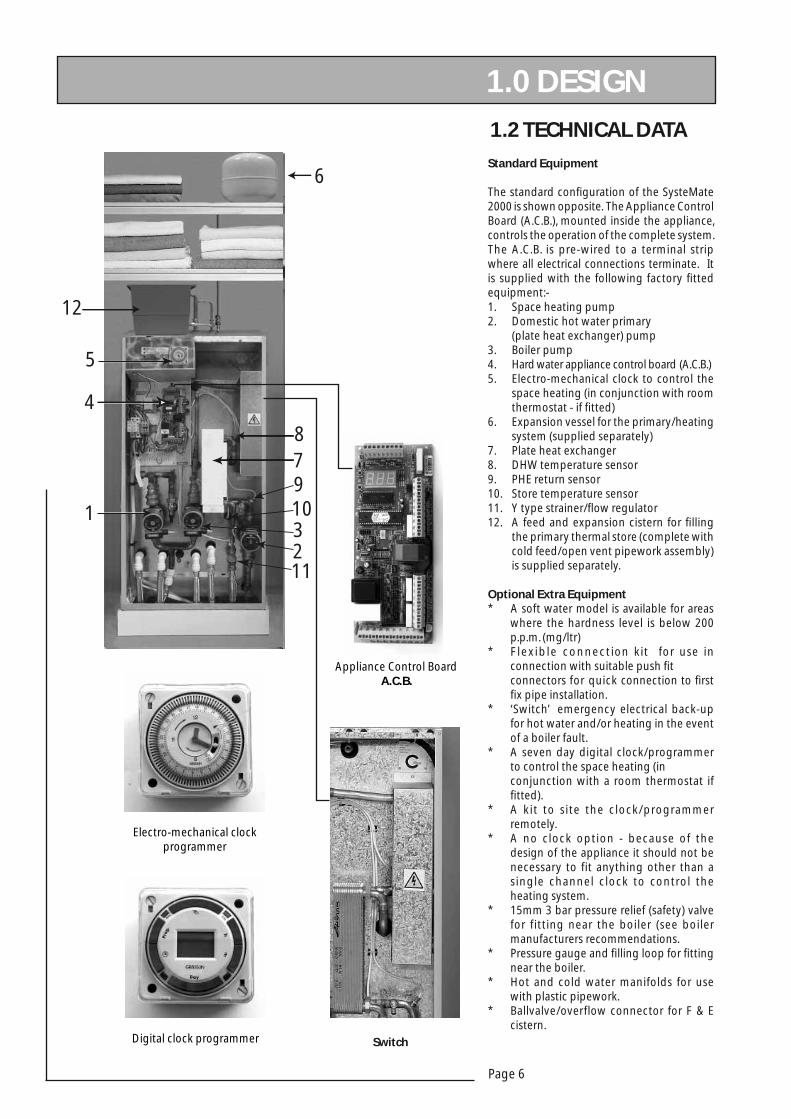
1.2 TECHNICAL DATA
Standard Equipment
The standard confi guration of the SysteMate 2000 is shown opposite. The Appliance Control Board (A.C.B.), mounted inside the appliance, controls the operation of the complete system. The A.C.B. is pre-wired to a terminal strip where all electrical connections terminate. It is supplied with the following factory fi tted equipment:-1. Space heating pump2. Domestic hot water primary (plate heat exchanger) pump3. Boiler pump4. Hard water appliance control board (A.C.B.)5. Electro-mechanical clock to control the space heating (in conjunction with room thermostat - if fi tted)6. Expansion vessel for the primary/heating system (supplied separately)7. Plate heat exchanger8. DHW temperature sensor9. PHE return sensor10. Store temperature sensor11. Y type strainer/fl ow regulator12. A feed and expansion cistern for fi lling the primary thermal store (complete with cold feed/open vent pipework assembly) is supplied separately.
Optional Extra Equipment* A soft water model is available for areas where the hardness level is below 200 p.p.m. (mg/ltr)* Flexible connection kit for use in connection with suitable push fi t connectors for quick connection to fi rst fi x pipe installation. * ‘Switch’ emergency electrical back-up for hot water and/or heating in the event of a boiler fault.* A seven day digital clock/programmer to control the space heating (in conjunction with a room thermostat if fi tted).* A kit to site the clock/programmer remotely.* A no clock option - because of the design of the appliance it should not be necessary to fit anything other than a single channel clock to control the heating system.* 15mm 3 bar pressure relief (safety) valve for fitting near the boiler (see boiler manufacturers recommendations.* Pressure gauge and fi lling loop for fi tting near the boiler.* Hot and cold water manifolds for use with plastic pipework. * Ballvalve/overflow connector for F & E cistern.
1.0 DESIGN
Appliance Control BoardA.C.B.
Electro-mechanical clock programmer
Digital clock programmer Switch

Page 7
SYST
EMA
TE 2
00
0
1.0 DESIGN 1.2 TECHNICAL DATA
Note: The dimensions below do not allow for the100mm high installation base.
The following table of minimum cupboard dimensions only allow the minimum space required for the appliance (including the F & E cistern and expansion vessel) and any extra space required for shelving etc in the case of airing cupboards etc must be added.
D
600mm min clear opening- if located directly in front of theappliance. Maintenance
access
Min maintenanceaccess - to comply
with the WaterRegulations if a
ballvalve is being fited
APPLIANCE
E C
300m
m
420m
m 450m
m*
600m
m10
0mm
F A
F & E Cistern
F & E Cistern plan
290mm*
ExpansionVessel25 litre
* Note : 12 litre vessel (supplied with SM 125 - 185) Size 280mm diam x 300mm long
Note : 225mm is considered adequate access if the ballvalve is not beingfitted i.e. manual fill is being used
280mm
25 litre Expansion
Vessel(Supplied
with SM 210-225)
plan
B
350m
m
SNOISNEMIDECNAILPPA
ledoMthgieH htdiW htpeD
A B C
521MS mm0411 mm595 mm595
541MS mm0411 mm595 mm595
581MS mm0531 mm595 mm595
012MS mm5941 mm595 mm595
522MS mm0761 mm595 mm595
SNOISNEMIDDRAOBPUCMUMINIM
ledoMthgieH htdiW htpeD
F D E
521MS mm0981 mm007 mm006
541MS mm0981 mm007 mm006
581MS mm0012 mm007 mm006
012MS mm5422 mm007 mm006
522MS mm0242 mm007 mm006
Note: The above dimensions are based on the Appliance and the F & E cistern (fi tted with a ballvalve) being in the same cupboard. If the manual fi ll method is chosen the heights can be reduced by 125mm.

Page 8
1.0 DESIGN
1.2 TECHNICAL DATA
Cut out area throughbase of unit - showingrecommended pipeworkriser positions.
120
408
595
595
555
REAR
PLAN
478 508
453
22mm Open Vent (for thermal store)15mm Cold feed (for thermal store)
REMOVABLE FRONT ACCESS PANEL
325
45TOPHe
atin
g Flo
w
Heat
ing
Retu
rn
Boile
r Flo
w
Prim
ary R
etur
nTo
wel R
ail C
ircui
t
Boile
r Ret
urn
Hot S
uppl
y
Cold
Main
s Sup
ply
The SysteMate 2000 units are supplied on an installation base to allow the pipe runs to connect to the appliance from any direction. It is easier if all pipes protrude vertically in the cut out area shown. Compression or push fit connections can be used and we do offer a set of flexible connectors as
an option, (for use with suitable push fit connectors only). All pipe positions are approximate and subject to a tolerance of +/- 10mm in any
direction. Space for a 15mm cold water supply and a 22mm warning/overflow pipe for the separate feed and expansion cistern (if
fitted) will also be required.
If a warning/overflow pipe is NOT provided the F & E cistern should be filled from a temporary hose connection incorporating a double check
valve. This can be from a temporary hose connection supplied from any cold water tap or from a permanent cold branch provided adjacent to the
F & E cistern. The temporary connection must be removed once the appliance is filled.
15mm Expansion Vessel
Prim
ary F
low
Towe
l Rail
Circ
uit
70
405450
450360
330297
225195
157
55
* Drawing not to scale.
Page 9
SYST
EMA
TE 2
00
0
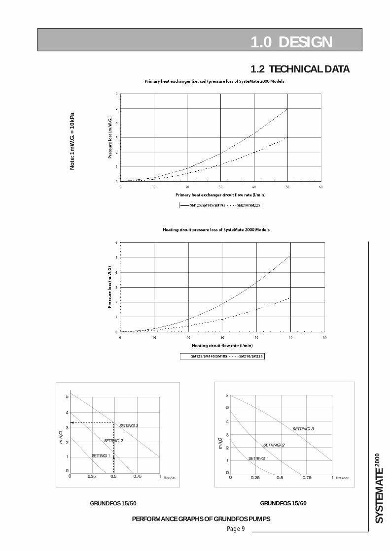
1.2 TECHNICAL DATA
PERFORMANCE GRAPHS OF GRUNDFOS PUMPS
1.0 DESIGN
GRUNDFOS 15/50 GRUNDFOS 15/60
litres/sec
6
litres/sec
No
te: 1
mW
.G. =
10
kPa

Page 10
1.3 SYSTEM DETAILSHot and Cold Water System
GeneralA schematic layout of the hot and cold water services in a typical small dwelling is shown below. SysteMate 2000 will operate at mains pressures as low as 1 bar and as high as 5 bar although the recommended range is 2-3 bar. If the manifolds (available as an optional extra) are being used the inlet pressure to the manifold must be a minimum of 2 bar. It is also important to check that all other equipment and components in the hot and cold water system are capable of accepting the mains pressure available to the property. If the mains pressure can rise above 5 bar or the maximum working pressure of any item of equipment or component to be fi tted in the system, a suitable pressure limiting (reducing) valve will be required.
If you encounter a situation where the water pressure is adequate but fl ow rates are poor please contact our technical helpline for details of an effective solution.
Note: Each SysteMate 2000 is fi tted with a strainer and fl ow regulator on the cold mains supply connection. If the supply pressure is less than 2 bar or if the manifolds (available as an optional extra) are being used or if all taps are provided with fl ow regulators the fl ow regulator on the cold inlet should be removed.
No check valve or similar device should be fi tted on the cold water supply branch to the SysteMate 2000.
To comply with the Benchmark Guidance Note for Water Treatment in Heating and Hot Water Sytems the installer should check the hardness level of the water supply and if necessary fi t an in-line scale inhibitor/reducer to provide protection to the whole of the domestic water system. See Appendix C for a copy of the relevant part of the Benchmark Guidance Note.
1.0 DESIGN
Note: The diagram above shows the F & E cistern with a ballvalve and warning/overfl ow pipe which can be fi tted if required. However, the standard preferred arrangement is for the cistern to be manually fi lled from a temporary hose connection fi tted with a double check valve.
When specifying this appliance we would recommend that for hardness levels above 200ppm (mg/l) a hard water appliance is used. For hardness levels above 280ppm (mg/l) we would recommend that some form of in-line scale inhibitor/reducer is recommended by one of the water treatment companies listed in the Benchmark Guidance Note (See Appendix C).
The hot water fl ow rate from the SysteMate 2000 is directly related to the adequacy of the cold water supply to the dwelling. This must be capable of providing for those services, which could be required to be supplied simultaneously, and this maximum demand should be calculated using procedures defi ned in BS 6700.
If a water meter is fi tted in the service pipe, it should have a nominal rating to match the maximum hot and cold water peak demands calculated in accordance with BS 6700. This could be up to 80ltr/min in some properties.
Page 11
SYST
EMA
TE 2
00
0
1.3 SYSTEM DETAILSHot and Cold Water System
Pipe Sizing / Materials
To achieve even distribution of the available supply of hot and cold water, it is important in any mains pressure system, that the piping in a dwelling should be sized in accordance with BS 6700. This is particularly important in a large property with more than one bathroom.
However, the following rule of thumb guide lines should be adequate for most smaller property types as long as water pressures are within the recommended range of 2-3 bar.
1. A 15mm copper or equivalent external service may be sufficient for a small 1bathroom dwelling (depending upon the flow rate available), but the minimum recommended size for new dwellings is 22mm (25mm MDPE).2. The internal cold feed from the main incoming stop tap to the SysteMate should be run in 22mm pipe. The cold main and hot draw-off should also be run in 22mm as far as the branch to the bath tap. 3. The final branches to the hand basins and sinks should be in 10mm and to the baths and showers in 15mm. (1 metre recommended)4. We would recommend that best results for a balanced system are achieved
by fi tting appropriate fl ow regulators to each hot and cold outlet. This is particularly relevant where the water pressures are above the recommended water pressure range of 2-3 bar. See Appendix A for further details.
Note: If manifolds (available as an optional extra) are being used suitable fl ow regulators are automatically provided in the manifold and do not need to be provided at each outlet - See Appendix B for further details.
Note: If a warning/overfl ow pipe is NOT provided the F & E cistern should be filled from a temporary hose connection supplied from any cold water tap or from a permanent cold branch provided adjacent to the F & E cistern. The temporary hose must be fi tted with a double check valve and removed once the appliance is fi lled.
All the recommendations with regard to pipework systems in this manual are generally based on the use of BS/EN Standard copper pipework and fi ttings.
However, we are happy that plastic pipework systems can be used in place of copper internally as long as the chosen system is recommended for use on domestic hot and cold water systems by the manufacturer and is installed fully in accordance with their recommendations.
This is particularly important in relation to use of push fi t connections when using the optional fl exible hose kits - see 2.2 Installation, Pipework connections.
It is also essential that if an alternative pipework material/system is chosen the manufacturer confi rms that the design criteria of the new system is at least equivalent to the use of BS/EN Standard copper pipework and fi ttings.
Taps/Shower Fittings
Aerated taps are recommended to prevent splashing.Any type of shower mixing valve can be used as long as both the hot and cold supplies are mains fed. However, all mains pressure systems are subject to dynamic changes particularly when other hot and cold taps/showers are opened and closed, which will cause changes in the water temperature at mixed water outlets such as showers. For this reason and because these are now no more expensive than a manual shower we strongly recommend the use of thermostatic showers with this appliance. The shower head provided must also be suitable for mains pressure supplies.However, if it is proposed to use a ‘whole body’ or similar shower with a number of high fl ow/pressure outlets please discuss with the Gledhill technical department.
1.0 DESIGN
If the length of the hot water draw off pipework is excessive and the delivery time will be more than 60 seconds before hot water is available at the tap, you may wish to consider using trace heating to the hot water pipework such as the Raychem HWAT system. The appliance has not been designed to suit a re-circulating domestic hot water circuit.Please consult Gledhill Technical Department for further details.
It is important that the cold water pipework is adequately separated/protected from any heating/hot water pipework to ensure that the water remains cold and of drinking water quality.
Hot and Cold Water System.
The hot water supply to a shower-mixing valve should be fed wherever practical directly from the SysteMate 2000 or be the fi rst draw-off point on the hot circuit. The cold supply to a shower-mixing valve should wherever practical be fed directly from the rising mains via an independent branch. The shower must incorporate or be fi tted with the necessary check valves to provide back-syphonage protection in accordance with the Water Regulations. The supply of hot and cold mains water directly to a bidet is permitted provided that it is of the over-rim fl ushing type and that a type ‘A’ air gap is incorporated.

Page 12
1.0 DESIGN
Heating System
General
A schematic layout of the heating system in a typical small dwelling is shown above.
The fl ow and return from the boiler must always run directly to the SysteMate 2000 and the fl ow should rise continuously to facilitate venting. The heating circuit is taken from the SysteMate 2000 and is piped in the conventional manner.
The SysteMate 2000 is only suitable for a sealed heating system and therefore boiler/heating pipework can run at a higher level than the store.
It is recommended that the F & E cistern for the appliance is fi tted at high level in the same cupboard as the SysteMate 2000. However, it can be fi tted remotely up to 10m above the base of the SysteMate 2000 i.e. the maximum static pressure in the store must not exceed 1 bar.
It is recommended that the expansion vessel is fi tted at high level in the appliance cupboard alongside the F & E cistern.
The performance of the system pump and the pressure losses through the SysteMate 2000 primary coil circuit are shown in1.2 Technical Data. The nett pump head available for the heating circuit can be determined from these fi gures and this nett pump head should be used for sizing the heating circuit pipework.
If any radiators are located above the level of the SysteMate 2000 the system should be designed so that gravity circulation does not occur when the heating pump is not running. To be certain of preventing this it is recommended that a check valve, or valves, are fi tted on the vertical fl ow pipes.
1.3 SYSTEM DETAILS
For example: At 24 litres/min primary fl ow rate, the pressure loss through the SysteMate 2000 model SM210 (coil and fi ttings) is 2.1m W.G. (21kPa). The maximum pump head available at 24 litres/min and setting 3 is 3.2m H
2O (32kPa),
therefore 1.1m W.G. (11kPa) is available for the boiler circuit.
With sealed heating systems air is released during the first few weeks of operation. This will need to be vented and the system re-pressurised.
The overfl ow/warning pipe should be installed in a material suitable for a heating system feed and expansion cistern in accordance with BS 5449.
An automatic bypass is fi tted on the SysteMate 2000 to compensate for pressure (i.e. fl ow) rate changes in the heating circuit e.g. when the thermostatic radiator valves close. The system does not require any other bypass valves but a bypass radiator used in conjunction with a room thermostat is suitable.
There shall be no permanent connection to the mains water supply for fi lling the system, even through a non-return valve without the approval of the Local Water Authority. An approved filling loop is required with the SysteMate 2000 (available as an optional extra) which this should be disconnected after commissioning the system. This should be located adjacent to the boiler along with a suitable gauge and pressure relief valve (also available as optional extras) as shown opposite.
RemoteF&E cistern
Cold feed
Hot
Cold
Open Vent
Boiler
ExpansionVessel
Pressure relief (safety) valve
Components fitted within the appliance case
Automatic bypass valve
Filling loop
Pressure gauge

Page 13
SYST
EMA
TE 2
00
0
1.0 DESIGN
1.3 SYSTEM DETAILSHeating System
Pipe Sizing/Materials
The SysteMate 2000 is designed to be installed with any condensing or non condensing boiler which is suitable for a sealed heating system (i.e. fi tted with an overheat thermostat) and is capable of delivering hot water at a minimum of 80oC.
The primary pipework connecting the boiler and the thermal store should be sized to achieve a maximum of 11°C rise across the boiler or the maximum temperature rise specifi ed by the boiler manufacturer, whichever is smaller, but in any instance it should not be less than 22mm copper tube.
If the boiler is a condensing type the boiler must be set to operate at a normal 82oC fl ow 71oC return system.
Note: There should be no valves in the pipework connecting the boiler to the SysteMate 2000.
The heating circuit operates on the normal primary boiler temperatures i.e. 82°C fl ow and 71°C return. Therefore any traditional hot water radiators or convectors can be used with this system and no special over-sizing of the heat emitters is necessary.
All the recommendations with regard to pipework systems in this manual are generally based on the use of BS/EN Standard copper pipework and fi ttings.
However, we are happy that plastic pipework systems can be used in place of copper internally as long as the chosen system is recommended for use on domestic heating systems by the manufacturer and is installed fully in accordance with their recommendations. We always recommend the use of barrier pipe for these systems.
It is also essential that if an alternative pipework material/system is chosen the manufacturer confi rms that the design criteria of the new system is at least equivalent to the use of BS/EN Standard copper pipework and fi ttings.
Boiler Size
It is only necessary to calculate the heating requirements in accordance with BS 5449. The allowances shown below should be added for domestic hot water. The control system automatically gives priority to hot water when necessary.
Boiler Sited Below SysteMate 2000
The fl ow pipe from the boiler to the SysteMate 2000 must rise continuously. No valve shall be fi tted in the primary fl ow pipe as this forms the expansion pipe to the expansion vessel.
The size of the primary pipework connecting the boiler to the SysteMate 2000 must not be less than 22mm (or that specifi ed by the boiler manufacturer).
Boiler
SM 2000
ExpansionVessel
Remote F & ECistern
Boiler Return
Boiler Flow
Pressure relief (safety) valve
Filling loop
Pressure gauge
Allowance for Domestic Hot Water
Model (kW)
SM125 2
SM145 3
SM185 3
SM210 3.5
SM225 4
Page 14
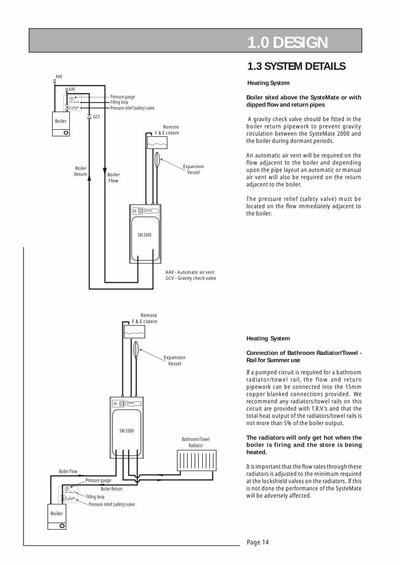
If a pumped circuit is required for a bathroom radiator/towel rail, the flow and return pipework can be connected into the 15mm copper blanked connections provided. We recommend any radiators/towel rails on this circuit are provided with T.R.V.’s and that the total heat output of the radiators/towel rails is not more than 5% of the boiler output.
The radiators will only get hot when the boiler is firing and the store is being heated.
It is important that the fl ow rates through these radiators is adjusted to the minimum required at the lockshield valves on the radiators. If this is not done the performance of the SysteMate will be adversely affected.
Heating System
Connection of Bathroom Radiator/Towel - Rail for Summer use
1.0 DESIGN 1.3 SYSTEM DETAILS
Boiler sited above the SysteMate or with dipped fl ow and return pipes
A gravity check valve should be fi tted in the boiler return pipework to prevent gravity circulation between the SysteMate 2000 and the boiler during dormant periods.
An automatic air vent will be required on the flow adjacent to the boiler and depending upon the pipe layout an automatic or manual air vent will also be required on the return adjacent to the boiler.
The pressure relief (safety valve) must be located on the fl ow immediately adjacent to the boiler.
Heating System
RemoteF & E cistern
Boiler
ExpansionVessel
AAV
AAV
GCV
SM 2000
BoilerFlow
BoilerReturn
AAV - Automatic air ventGCV - Gravity check valve
Pressure relief (safety) valveFilling loopPressure gauge
RemoteF & E cistern
ExpansionVessel
Boiler
SM 2000
Boiler Return
Boiler Flow
Bathroom/TowelRadiator
Pressure relief (safety) valve
Filling loop
Pressure gauge

Page 15
SYST
EMA
TE 2
00
0
1.3 SYSTEM DETAILSHeating System
Expansion Vessel Requirements
The SysteMate expansion vessel is pre-charged to 1.0 bar. The maximum water content of the heating system (boiler + radiators + connecting pipework + primary coil but NOT store volume) must not be greater than those shown in the table below.
A fi gure of 4.5 litres/kW of installed radiator capacity can be used for a preliminary assessment of the water content of the heating system.
The values presented in the table are based on a maximum boiler fl ow temperature of 93oC. The expansion vessel must be suitable to accommodate the change in volume of the water in the system when heated from 10oC to 110oC as specifi ed in BS 5449: 1990 clause 16.2.
The primary heating coil and pipework volumes are shown in the table in 1.2 Technical Data.
In normal circumstances an initial vessel and system charge pressure of 1 bar is suitable for most domestic purposes.
The minimum system pressure should not be less than the static head plus 0.5 bar i.e. the height of the highest point in the system above the expansion vessel plus a margin of 0.5 bar.
If the system volume is greater than that shown in the table at the selected operating conditions then an additional expansion vessel must be fi tted.
1.0 DESIGN‘Switch’
The SysteMate 2000 can be ordered with the option of ‘Switch’ which provides a 9kW electrical emergency back up in the case of failure of the main heat source i.e. gas boiler.
This must NOT be used to provide hot water only in summer if the main system is working correctly.
If Switch is ordered the electrical supply will need to take account of the increased load. Full details of the requirements are provided in Section 2.1 Site Requirements and 2.2 Installation.
Otherwise the design requirements are the same as the standard appliance.
Switch can operate on ‘hot water’ or ‘hot water and heating’ modes. In the former only hot water pump and electric heating element are energized. In the latter the heating system pump is also energized. This means that the heating will be on permanently unless manually switched back to the ‘hot water’ only position.
It also means that wherever Switch is being used the normal domestic hot water temperature controls are over-ridden. Initially dependent on the fl ow rate/store temperature hot water can be delivered at the tap at temperatures as high as 75°C. A warning notice to this effect is provided in the front of the appliance.
However, once the initial store temperature has been reduced the Switch element thermostat will reduce the temperature at the tap to no more than 65°C. Full details of how to operate the system are provided on a label fi xed to the front of the appliance.
12 Litre Vessel i.e. SM 125/145/185
Maximum Recommended Heating System Volumes
Safety valve setting (bar) 3.0
Vessel charge pressure (bar) 0.5 1.0 1.5
Initial system pressure (bar) 0.5 1.0 1.5 1.0 1.5 2.0 1.5 2.0
Maximum permitted systemvolume (litres)
140 80 40 110 60 27 70 35
25 Litre Vessel i.e. SM 210/225
Maximum Recommended Heating System Volumes
Safety valve setting (bar) 3.0
Vessel charge pressure (bar) 0.5 1.0 1.5
Initial system pressure (bar) 0.5 1.0 1.5 1.0 1.5 2.0 1.5 2.0
Maximum permitted systemvolume (litres)
270 160 85 200 115 50 140 65

Page 16
2.0 INSTALLATION
2.1 SITE REQUIREMENTS
The appliance is designed to be installed in an airing/cylinder cupboard and the relevant minimum dimensions are provided in section 1.2 Technical Data.
Because of the ease of installation we recommend that the cupboard construction is completed and painted before installation of the appliance. The cupboard door can be fi tted after installation.
If the unit needs to be stored prior to installation it should be stored upright in a dry environment and on a level base/fl oor.
Installation and maintenance access is needed to the front of the appliance and above the F & E cistern. See Technical Data section for further details.
The minimum dimensions contained in section 1.2 Technical Data allow for the passage/connection of pipes to the appliance from any direction as long as the appliance is installed on the installation base provided. If the installation base is not used extra space may be needed to allow connection to the pipework and the whole of the base area should be continuously supported on a material which will not easily deteriorate if exposed to moisture.
The fl oor of the cupboard needs to be level and even and capable of supporting the weight of the appliance when full. Details of the weight when full is provided in section 1.2 Technical Data.
The appliance is designed to operate as quietly as practicable. However, some noise (from pumps etc) is inevitable in any heating system. This will be most noticeable in cupboards formed on bulkheads, or at the mid span of a suspended fl oor. In these cases the situation can be improved by placing the appliance on a suitable sound deadening material (i.e. carpet underlay or similar).
Cupboard temperatures will normally be higher than in a conventional system and the design of the cupboard and door will need to take this into account. No ventilation is normally required to the cupboard.
A suitable location will be needed for the separate feed and expansion cistern and expansion vessel. This will often be at high level in the cupboard housing the SysteMate 2000. The dimensions and clearances are provided in section 1.2 Technical Data. The location will need to provide a suitable route for the cold feed/expansion pipe and the open safety vent pipe for the appliance as well as the connecting pipe to the system expansion vessel. The location will also need to provide a suitable route and discharge position for the warning/overfl ow pipe and the ballvalve supply from the mains cold water system if these are being fi tted.
Note: The standard appliance is supplied with a cistern without a ballvalve/overfl ow for fi lling manually.
An electrical supply must be available which is correctly earthed, polarized and in accordance with the latest edition of the IEE requirements for electrical Installations BS 7671.
The electrical mains supply needs to be 230V/50Hz/1Ph
Connection must be made using a double-pole linked isolator with a contact separation of 3mm in both poles which is located within 1m of the appliance. The supply must only serve the appliance.
The supply to the standard appliance shall be fused at 3 amp - nominal maximum full load current for all SM models = 1.4 amps (this does not include the boiler).
Electrical Supply requirements for SysteMate 2000 with Switch
If the ‘Switch’ electrical emergency backup is being provided, the minimum breaking capacity of the main isolation switch and cable sizes/lengths at 230V shall follow the recommendations in the table below.
Nominalfull loadcurrent
Min rating of isolating
switch
Cablesize
Max. recommendedcable run-based
on 9.2V drop and 0.4 second disconnection
time using a type 1 or B breaker
41.0 Amps
45 Amps 10mm2 49 metres
Recommended circuit protection device - based on 0.4 second disconnection time
45A type 1 - M.C.B. to BS 387145A type B circuit breaker to BS EN 60898

Page 17
SYST
EMA
TE 2
00
0
2.2 INSTALLATION
2.0 INSTALLATION
HANDLINGWhen lifting the unit work with someone of similar build
and height if possible. Choose one person to call the signals.
Lift from the hips at the same time, then raise the unit to the desired level.
Move smoothly in unison.Larger units may need team lift.
Preparation/placing the appliance in position.
Details of the recommended positions for termination of the fi rst fi x pipework are provided in section 1.2 Technical Data. The pipework can be located or its position checked using the template provided with each appliance. If these have been followed installation is very simple and much quicker than any other system. The appliance is supplied shrink wrapped on a timber installation base. Carrying handles are also provided in the back of the casing.
The feed and expansion cistern complete with ballvalve, cold feed/expansion and overflow/warning fi ttings are provided in a separate box along with the system expansion vessel. If fl exible connections have been ordered these will also be inside the feed and expansion cistern.
The appliance should be handled carefully to avoid damage and the recommended method is shown opposite. Before installation the site requirements should be checked and confi rmed as acceptable. The plastic cover and protective wrapping should be removed from the appliance and the installation base (provided) placed in position.
The appliance can then be lifted into position in the cupboard on top of the base and the front panel removed by unscrewing the 2 screws and lifting the door up and out (see opposite) ready for connection of the pipework and electrical supplies. The feed and expansion cistern support shall be installed ensuring that the base is fully supported and the working head of the appliance is not exceeded. The recommended access for maintenance must also be provided - see section 1.2 Technical Data.
Note: Although the above guidance is provided any manual handling/lifting operations will need to comply with the requirements of the Manual Handling Operations Regulations issued by the H.S.E.
The appliance can be moved using a sack truck on the rear face although care should be taken and the route should be even.
In apartment buildings containing a number of storeys we would recommend that the appliances are moved vertically in a mechanical lift.
If it is proposed to use a crane expert advice should be obtained regarding the need for slings, lifting beams etc.
A specifi c manual handling assessment is shown in Appendix D at the rear of this manual.

Page 18
The position of the pipework connections is shown opposite. The connection sizes and dimensions are listed in Section 1.2 Technical Data.
All the connections are also labelled on the appliance. It is essential that the pipework is connected to the correct connection.
The connections can be hard piped but we recommend the use of fl exible connections (available as an optional extra).
When using push fit connectors with the fl exible hose kits it is important to check that they are compatible. Written approval has already been obtained for:-Hepworth - Hep2O BiTiteJohn Guest - Speedfi tYorkshire - Tectite
However, as similar assurances cannot be obtained for Polypipe fittings we cannot recommend their use.
Connections A, B, D, E, F, G, H, I, and L are plain ended copper pipe.
Connections C & J are compression fi ttings.
Connection K is a RC½ (½” BSPT internal)
A - Safety open ventB - Cold feed/expansionC - Expansion vessel pipeD - Central heating fl owE - Central heating returnF - Primary fl ow (from boiler)G - Primary return (for summer use bathroom towel rail circuit)H - Primary return (to boiler)I - Domestic hot waterJ - Incoming mains waterK - Drain (valve is not provided with the appliance)L - Primary fl ow (for summer use bathroom towel rail circuit)
Note: The safety open vent and cold feed/expansion should be connected to the F & E cistern using the pipework assembly provided.
2.0 INSTALLATION2.2 INSTALLATIONPipework connections
D E FGHI J K L
A B C
Page 19
SYST
EMA
TE 2
00
0
2.2 INSTALLATION
2.0 INSTALLATION
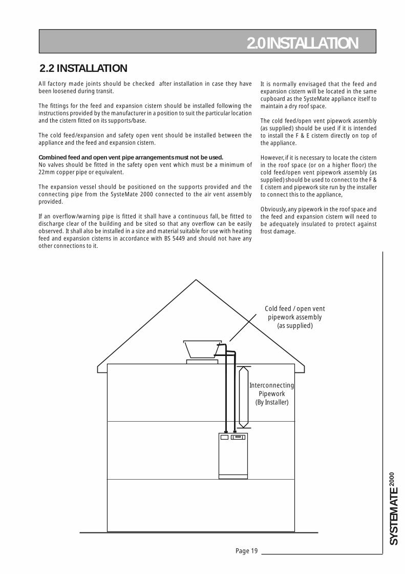
It is normally envisaged that the feed and expansion cistern will be located in the same cupboard as the SysteMate appliance itself to maintain a dry roof space.
The cold feed/open vent pipework assembly (as supplied) should be used if it is intended to install the F & E cistern directly on top of the appliance.
However, if it is necessary to locate the cistern in the roof space (or on a higher floor) the cold feed/open vent pipework assembly (as supplied) should be used to connect to the F & E cistern and pipework site run by the installer to connect this to the appliance,
Obviously, any pipework in the roof space and the feed and expansion cistern will need to be adequately insulated to protect against frost damage.
All factory made joints should be checked after installation in case they have been loosened during transit.
The fi ttings for the feed and expansion cistern should be installed following the instructions provided by the manufacturer in a position to suit the particular location and the cistern fi tted on its supports/base.
The cold feed/expansion and safety open vent should be installed between the appliance and the feed and expansion cistern.
Combined feed and open vent pipe arrangements must not be used.No valves should be fi tted in the safety open vent which must be a minimum of 22mm copper pipe or equivalent.
The expansion vessel should be positioned on the supports provided and the connecting pipe from the SysteMate 2000 connected to the air vent assembly provided.
If an overflow/warning pipe is fitted it shall have a continuous fall, be fitted to discharge clear of the building and be sited so that any overfl ow can be easily observed. It shall also be installed in a size and material suitable for use with heating feed and expansion cisterns in accordance with BS 5449 and should not have any other connections to it.
Cold feed / open ventpipework assembly
(as supplied)
InterconnectingPipework
(By Installer)

Page 20
WIRING DIAGRAM - STANDARD SYSTEMATE 2000 APPLIANCE
2.0 INSTALLATION
2.2 INSTALLATION
KEY
BL BLUE
BR BROWN
G/Y GREEN/YELLOW
R RED

Page 21
SYST
EMA
TE 2
00
0
2.2 INSTALLATION
2.0 INSTALLATION
Make the connections as shown opposite on the terminal strip provided.
The appliance is provided with a link between terminals 9 and 11 on the terminal strip. This must be removed if a room thermostat is fi tted see opposite.
No Clock Models
• If a remote clock is not being provided links will be required between 21/22 and 22/23.• If a single remote clock is being provided a single link will be required between 21/22 to allow the appliance to provide hot water 24hrs/day.• If a two channel clock is being provided no links will be required. (A two channel clock is normally only required to eliminate noise caused by the boiler fi ring during the night).• Wire the connections from the clock as shown opposite.
Clamp the cables in the grips provided below the terminal strip and ensure all cables are routed to avoid hot surfaces.
Note: The appliance is provided with a 4.0mm earth cable from an earthing strap on the heating system bypass pipe to the earth stud on the wiring panel.
Electrical Connection - Standard Appliance
The SysteMate 2000 is pre-wired to a 12 way terminal strip from the A.C.B. and plumbers are well able to complete the electrical installation provided they adhere strictly to the IEE Requirements for Electrical Installations BS 7671. A schematic arrangement of the wiring is shown on page 24.
All the terminals are suitably labelled.Note: Do not attempt the electrical work unless you are competent to carry it out to the above standards.
Before commencing check that the power source is in accordance with section 1.2 Site Requirements and ensure that it is isolated.
Run the external wiring through the service slot provided in the base of the appliance.
It is recommended that the 3 core input cable from the isolator to the appliance is not less than 1.5mm2 PVC grade to BS 6500.
Wiring guide from Clock to ACB
Neutral - Terminal 20
Permanent Live (to clock) - Terminal 21
Hot Water Channel Switched Live (from clock) - Terminal 22 (only required with 2 channel clock)
Heating Channel Switched Live (from clock) - Terminal 23
* If the power consumption of the boiler is more than 230 watts the supplies to the boiler should be provided via a relay as shown above.
If the appliance is provided with Switch the supplies to the boiler should be taken from the outlet side of FS3 and the adjacent neutral connector and earth post. (see wiring diagram on page 23)

Page 22
2.2 INSTALLATION
2.0 INSTALLATION
The SysteMate 2000 incorporates a pump overrun for the boiler pump and terminal 6 on the terminal strip (as shown on page 22) should only be used if the boiler requires a permanent live for another purpose.
The boiler manufacturers wiring instructions should be read in conjunction with this manual.
Before switching on the electrical supply check all the factory made terminal connections to ensure they have not become loose during transit.
Frost Protection
When frost protection is required for the whole house or where a base temperature is required during cold weather, then a frost thermostat should be wired across plug in terminals 21 and 23 on the A.C.B board.
An alternative to fitting a frost thermostat would be to set the programmer to constant during the time required and adjust the room thermostat to a suitable setting.
When frost protection is required for the boiler circuit only a frost thermostat and pipe mounted thermostat should be fitted. The pipe thermostat should be mounted on the primary return pipe adjacent to the boiler and both thermostats should be wired from the terminal strip as shown opposite.
10
1 2 3 4 5 6 7 8 9 10 11 12
Boiler Pump
ApplianceControlBoard(A.C.B.)
Pipe MountedThermostat (break ontemperature rise)
Frost Thermostat (make on temperature drop)

Page 23
SYST
EMA
TE 2
00
0
2.0 INSTALLATION2.2 INSTALLATION
WIRING DIAGRAM - SYSTEMATE 2000 WITH SWITCHKEY
BL BLUE
BR BROWN
G/Y GREEN/YELLOW
R RED
BLK BLACK
Y YELLOW
WH WHITE

Page 24
2.0 INSTALLATION
2.2 INSTALLATIONElectrical Power Supplies - SysteMate 2000 with Switch.
A heavy duty electrical supply, see table on page 16, is required for this model and we recommend that a fully qualifi ed electrician must undertake this work.
The electrical installation must comply with the IEE Requirements for Electrical Installations BS 7671.
Note: do not attempt the electrical work unless you are competent to carry it out to the above standards.
A 10.0mm2 power cable is fi tted with a 3 metre tail for the installer to connect to an isolator which must not be more than 2 metres away from the appliance.
A schematic arrangement of the internal wiring is shown on page 24.
All terminals are labelled.
Before commencing check that the power supply source (i.e. isolator) is in accordance with section 1.2 Site Requirements and ensure it is isolated.
Run the 10mm2 cable provided through the service slot provided in the base of appliance and connect to the isolator as follows:-
red • liveblack • neutralgreen/yellow • earth
Check the cables are secure in the grips provided below the terminal strip and ensure they are not in contact with any hot surfaces.
The recommendations contained under Electrical Connection - Standard Appliance should be followed when connecting a remote clock, room thermostat, boiler etc.
WARNING : DO NOT SWITCH ON ELECTRIC BACKUP, IF FITTED, UNTIL THE APPLIANCE HAS BEEN FULLY COMMISSIONED i.e. PRIMARY STORE IS FILLED AND VENTED.
WARNING: IF THE SYSTEMATE IS FITTED WITH AN OPTIONAL ELECTRIC BACKUP SYSTEM I.E. ‘SWITCH’.
IMPORTANT: ELECTRICIAN/INSTALLER PLEASE NOTE.
THE 2 x 25A FUSES FOR THE ‘SWITCH’ ELECTRIC BACKUP SYSTEM ARE SUPPLIED IN THE ACTIVE FUSE CARRIER. THE GAS BOILER CAN BE COMMISSIONED WITHOUT INSERTING THESE FUSES.
IT IS IMPORTANT THAT THE GAS BOILER IS COMMISSIONED BEFORE TESTING OR USING EMERGENCY SWITCH FACILITY.
AFTER THE GAS BOILER HAS BEEN COMMISSIONED CUT AND REMOVE THE PLASTIC TIE AND PUSH DOWN FULLY THE CARRIAGE TO COMMISSION THE SWITCH FACILITY.
Page 25
SYST
EMA
TE 2
00
0
2.3 COMMISSIONING
2.0 INSTALLATION
Open the incoming stop valve and fill the domestic mains cold and hot water systems.
Check and adjust as necessary the expansion vessel air pressure to the figure specifi ed (normally 1.0 bar).
Fill the whole of the primary heating system with potable water through the fi lling loop provided adjacent to the boiler to the pressure required (normally 1.0 bar).
During fi lling vent air as necessary from the high points of the system including the manual air vents provided on the appliance and the feed to the expansion vessel.
Fill the appliance i.e. SysteMate 2000 through the feed and expansion cistern fl ush and refi ll.
Check the water level in the feed and expansion cistern and adjust the ballvalve if necessary.
Check the warning pipe is installed correctly, has a continuous fall and is not blocked i.e. discharges water freely.
Check the whole of the primary heating and domestic hot and cold distribution systems for leaks.
It is essential that all systems function properly for optimum performance.
To achieve this, the primary system should be commissioned in accordance with good practice and generally in accordance with the requirements of BS 6798, BS 5449 and BS 7593.
Full details of the requirements are given in PAS 33:1999 under Section 10 Commissioning.
When using either cleansing or corrosion inhibitor chemical, the manufacturers instructions must be followed.
Cleansing the Primary System
It is very important to ensure that the Primary system is cleaned using a suitable cleansing agent such as Sentinel X300 or Fernox Superfl oc to ensure that any fl ux residues/installation debris are removed.
The volumes/concentration should be calculated in accordance with the manufacturers instructions allowing the volume for the primary coil shown in the Table in 1.2 Technical Data.
Primary Water System Treatment
Although the SysteMate 2000 has no special water treatment requirements, the radiators and other parts of the circuit will benefi t from the application of a scale and corrosion inhibitor such as Sentinel X100 or a Protector such as Fernox MB1.
The volumes/concentration should be calculated in accordance with the manufacturers instructions allowing the volume for the primary coil shown in the Table in 1.2 Technical Data.
POWERFLUSHING/CLEANING OF THE HEATING SYSTEM
If it is proposed to ‘powerfl ush’ the heating system we would recommend that the SysteMate appliance is isolated from the heating system being cleaned. Failure to do this could seriously damage the appliance.
When carrying out the work always comply fully with the manufacturers instructions for the powerfl ushing equipment being used.
If in any doubt please consult our Technical Helpline.

Page 26
2.3 COMMISSIONING
Fully flush and, when necessary, chlorinate the hot and cold water system in accordance with the recommendations in the Model Water Byelaws and BS 6700.
Commissioning the SysteMate Control System
The SysteMate control system will automatically commission itself to match the ac tual performance of the installed boiler but the thermostat on the boiler should be left at maximum initially.
The control system/A.C.B has been initialised at the factory and will operate automatically.
However, the operation of the control system should be checked as follows on the A.C.B (shown opposite).
1. Set the boiler thermostat to MAXIMUM2. Switch off heating on the clock/ programmer and room thermostat3. Check the jumper settings are correct. These must all be in the correct positions for the appliance to work correctly - see opposite for options. 4. Switch on the mains supply. The A.C.B. will automatically commission itself to suit the sytem/boiler and the dot after the ON the LED display will fl ash:
2.0 INSTALLATION
Once the system is fi nally fi lled turn down the servicing valve for the ballvalve in the F & E cistern to the point where the warning/overfl ow will cope with the discharge arising from a ballvalve failure.
If an overfl ow is not provided ensure the temporary connection to the ballvalve is isolated and removed from its connection to the cold water supply.
Cleansing Hot/Cold Water System Treatment
e.g.
1
2
3
4
APPLIANCE CONTROL BOARD (A.C.B)
4 = Not used on this appliance3 = Heating pump on2 = Boiler pump on1 = Boiler on
GreenLED'S
Fuse
JumperSettings
SW1
SW2 8
LED DISPLAY
BAR 1 - HT
BAR 2 - ST
BAR 3 - HW

Page 27
SYST
EMA
TE 2
00
0
When commissioning the system
• If the boiler is range rated, then adjust it to the maximum heat input.
• Check the boiler thermostat is set to maximum.
• Set the boiler pump speed so that the temperature difference across the boiler is about 11°C - when the space heating is off.
• Balance the heating system and set the heating system pump speed so that the temperature difference across the fl ow and return is not greater than 11°C.
Because the A.C.B is able to adjust to suit the water temperatures delivered by the boiler the thermostat should always be set at maximum during commissioning.
The temperature settings established during commissioning can be checked using push button switches sw1 and sw2 on the PCB as described in section 3.3 Fault Finding.
The clock/programmer provided on the appliance controls the heating system only and should be set to suit the householders requirements using the instructions shown on the separate leafl et and the label on the front of the appliance. If the appliance is fi tted with Switch (see page 17 and 25) the boiler should be switched off and Switch operated to ensure it is working correctly.
• When the selector knob is not in normal position, the PCB, room thermostat and the time clock are electrically isolated.
• When the selector knob is in HW only position the plate heat exchanger pump will run continuously at full speed.
• When the selector knob is in the HW and HTG position, the plate heat exchanger pump and the heating pump will run continuously.
2.3 COMMISSIONING
2.0 INSTALLATION
The control system is now initialised. The operation of the controls can now be checked.
1. Horizontal LED bar 2 ‘store’ will be lit. Boiler and boiler pump will be running and green LED’s 1 and 2 on the A.C.B will be switched on.
2. Once the store temperature has been satisfi ed, switch on space heating clock/ programmer and room thermostat.
• Horizontal LED bar 1 ‘HT’ will light.• Green LED 3 on the A.C.B will switch on. Heating pump will run.
3. Switch off space heating on clock/programmer or room thermostat
• Horizontal LED bar 1 ‘HT’ will switch off.• Green LED 3 on the A.C.B will switch off. Heating pump will switch off.
4. Open the hot tap
• Horizontal LED bar 3 ‘DHW’ on the LED display will light.• Domestic hot water pump will run.
5. Close the hot water tap
• Horizontal LED bar 3 will switch off• Domestic hot water pump will continue to run for a short period of time before switching off.
6. The A.C.B incorporates a 3 minute boiler pump overrun facility. Check green LED 2 remains lit for this period of time when the boiler switches off i.e. the thermal store reaches temperature.
The control functions have now been checked.
Let the boiler heat the store and when the store is satisfi ed, i.e. green LED’s 1 and 2 on the A.C.B are off, the radiator circuit and hot water can be checked and balanced in the normal way.
The boiler thermostat should be left at maximum for optimum performance/effi ciency.
NOTE : When using the SysteMate with a Keston C25 comply with the following :
The heating circuit and boiler circuit pumps in the SysteMate must not be disconnected. Although it is not necessary, the pump in the boiler may be disconnected (after consultations with the manufacturers). The speed of the boiler circuit pump in the SysteMate should be adjusted to give about a 15ºC temperature rise across the boiler. However, if this starts circulation in the heating circuit when the heating is off, the speed should be increased. The speed of the heating circuit pump in the SysteMate should be adjusted to give about an 11ºC temperature difference across the heating circuit.
• Check the DHW plate heat exchanger pump is set to maximum.• Check that there is no overflow when the whole of the system is fu l ly up to temperature. • Check that the heating system pressure is not greater than 2.0 bar when the whole of the system is up to temperature.• The domestic hot water pump should always be set at pump speed 3.

Page 28
2.0 INSTALLATION
2.3 COMMISSIONINGThis product is covered by the ‘Benchmark’ scheme and a separate commissioning/service log book is included with this product. This must be completed during commissioning and left with the product to meet the Warranty conditions offered by Gledhill.
On completion:-
1. Do ensure that the electrical connections (e.g. mains supply, room thermostat) to the unit are correct and tight.
2. Do ensure that the functioning and control of the system is explained to the occupant.
These Instructions should be placed along with the component manufacturers instructions in the pocket provided on the rear of the front panel. The front panel should then be refi tted.
NOTE:- With sealed heating systems air is released from the water during the fi rst few weeks of operation. This must be vented and the system repressurized.
Important Do’s and Don’ts
DO check the incoming mains water pressure and fl ow rate are adequate. (The preferred range of mains pressure is 2-3bar).
DO check that all plumbing and electrical connections are in accordance with the labelling on the thermal store.
DO check and ensure the air pressure side of the expansion vessel is set at 1.0 bar (or as specifi ed)
DO ensure the SysteMate is fi tted on a sealed primary (i.e. closed) system and the boiler is suitable (i.e. fi tted with an overheat thermostat)
DO adjust the ballvalve so that the water level in the appliance F & E cistern when the system is cold is correct and does not overflow when the appliance is at maximum temperature
DO turn down the servicing valve for the ballvalve in the F & E cistern, once the system is fi nally fi lled, to the point where the warning/overfl ow pipe will cope with the discharge arising from a ballvalve failure.
DO make sure that there is adequate clearance above the appliance F & E cistern to service the ballvalve.
DO ensure that the range rated appliances are set at the highest output and the boiler thermostat is set to maximum for all boilers.
DO insulate any exposed pipework in the SysteMate cupboard.
DO plumb the overfl ow/warning pipe (if fi tted) in a 20mm internal diameter pipe material which is suitable for use with a heating F & E cistern, in accordance with BS 5449 (such as copper) and ensure it has a continuous fall and discharges in a conspicuous external position.
DO check the pump settingsa. The boiler pump should be set to give a temperature difference across the boiler of 11°C or less.b. The heating pump should be set to give a temperature difference across the fl ow and return of not more than 11°C.c. The hot water plate heat exchanger pump should be set at maximum.
DO ensure that the bypass valve for the heating system is set correctly.
DON’T use a combined feed and vent on SysteMate installations.
DON’T use pipe smaller than 28mm between the boiler and the SysteMate when the boiler rating exceeds 20kW (about 68,000 Btu/h).
DON’T operate the ‘switch’ backup facility until the system is fully fitted, vented and commissioned.
DON’T place any clothing or other combustible materials against or on top of this appliance.

Page 29
SYST
EMA
TE 2
00
0
3.1 ANNUAL SERVICINGNo annual servicing of the SysteMate 2000 is necessary.
However, if required, the operation of the controls and a hot water performance test can be carried out when servicing the boiler to prove the appliance is working satisfactorily and within its specifi cation.
Free of charge replacements for any faulty components are available from Gledhill during the in-warranty period (normally 12 months).
However, if any component is damaged during installation e.g. the A.C.B. , by incorrect wiring by the installer, a new replacement must be ordered and paid for.
After this, spares can be obtained direct from Gledhill using the ‘Speed Spares’ service, or through any of the larger plumbers merchants/specialist heating spares suppliers.
Help and advice is also available from the Technical Helpline on 08449 310000.
However, all components are readily accessible and can be changed quickly and easily by the installer using common plumbing practice.
If it is necessary to replace any of the pumps fi tted to the appliance the pump head (motor pack) only should be removed as recommended by Grundfos. Assuming it is within warranty this will be accepted by a merchant as being covered by the Grundfos national service exchange agreement, as long as it is a complete pump i.e. alleged faulty motor pack and new base is left with the merchant. It is important when a pump has been replaced to ensure that any air is adequately vented.
3.0 SERVICING
3.2 CHANGING COMPONENTS

Page 30
3.3 SHORTS PART LIST
3.0 SERVICING
.oNyeK noitpircseD rerutcafunaMkcotS
.oNedoC
saGlicnuoC.oNtraP
1 nretsicnoisnapxednadeeF knatyloP 343BX
2 taolfllaB nospE/dleifsaM 924TF 605073
3 evlavllaB ateB 702TF 505073
4 evlavkcehcelgniS oCcitsalPliateD 840TG 97473E
4 gnisuohssarB oCssarBdnaldiM 940TG
5 snoitcennoc"½1htiwpmup05/51 sofdnurG 100BX 882483
6 snoitcennoc"½1htiwpmup06/51 sofdnurG 142BX
7 evlavpmupepytllabmm22 ocmeV 121BX 01062E
8 evlavpmupepytllabmm82 ocmeV 221BX
9 regnahcxetaehetalP pewS 710TG 46650E
01 )B.C.A(draoblortnocecnailppA kolE 552BX 85193E
11 rosneserotS kolE 941TG 22062E
21 rosnesnruterEHP kolE 351TG 42062E
31 rosneserutarepmet.W.H.D kolE 351TG 42062E
41 kcolclacinahcem-ortcelE nilssarG 512BX 378583
51 kcolclatigiD nilssarG 612BX 478583
61 )12T46(tatsomrehtlortnochctiwS 443BX
71 tnemelegnitaehhctiwS 143BX
81 .b.c.plortnochctiwS edulerP 683BX
91 bonklortnochctiwS 873BX
02 esabesuf03CA suetorP 883BX
12 yalerrewoP 892BX 36193E
22 pma5esufkaerbhgihmm02 283BX
32 esufCL5203 463BX 16193E
42 lesseVnoisnapxE.rtL21 ecnaileR 461GX
52 lesseVnoisnapxE.rtL52 ecnaileR 561GX
62 reniartsepyT'Y' 413BX
72 rotalugerwolF 680TG
82 retliFesioNcinortcelE 703BX

Page 31
SYST
EMA
TE 2
00
0
3.0 SERVICING
24 25
1 2 3 4 5
6 7 8 9
10
11 12/13 14 15
16 18 19
21
21
22 2320
17
26
27
28

Page 32
3. Causes of ‘Unsatisfactory Space Heating’
Check the boiler thermostat - this should be set at maximum.Check that the boiler fl ow temperature before it is switched off is adequate - it should not be less than 80°C.Check the operation and the settings of the heating programmer and the room thermostat.Check that the heating system pump is circulating the water to the radiator circuit.If some rooms are not being heated properly, then balance the system, adjust the pump speed and check the operation of the thermostatic radiator valves (if fi tted).
Overfl ow from Feed and Expansion Cistern
Check that the controlled level of water in the cistern is no higher than necessary. Adjust if required.
3.4 FAULT FINDING
Despite everyone’s best efforts some problems could occur and lead to complaints from the householder.
Complaints can be grouped into the following three main categories:-
1. The system is noisy2. Hot water service is unsatisfactory3. Space heating is unsatisfactory
The following checks should be carried out by the installer before calling the manufacturer.
1. Causes of a ‘Noisy’ System
Noisy pump operationCheck the level of water in the Appliance F & E cistern - adjust and vent the plate heat exchanger pump and system if necessary.Check and if necessary adjust the pressure in the heating/primary system and vent the system.Check the pump speed setting of the boiler pump - reduce if necessary but ensure that the temperature rise across the boiler does not exceed 11°C.Check the pump speed setting of the heating pump - reduce if necessary but ensure a temperature difference across the fl ow and return does not exceed 11°C.Check and adjust if necessary the heating system bypass valve.Check that the radiators are correctly balanced.
Noisy boiler operationCheck the fl ow rate through the boiler at full gas rate by measuring the temperature rise across the boiler. If the temperature rise is greater than 11°C, then increase the pump speed. Check and adjust if necessary the pressure in the heating/primary system.Check and vent the system if necessary.
Noise when hot water tap is openedIf the plate heat exchanger pump is noisy when the hot water tap is opened, then check the level of water in the appliance F & E cistern and vent the pump if necessary.Water hammer - loose pipework and/or tap washers.
2. Causes of ‘Unsatisfactory Hot Water Service’
Check that the SysteMate is full of water i.e. level of water in the appliance F & E cistern is correct when system is cold.Check boiler thermostat - this should be set at maximum.Check that the boiler fl ow temperature is adequate when it stops fi ring. Boilers should provide a fl ow temperature of 82 ± 3°C but temperatures as low as 76°C will allow the SysteMate 2000 to provide a satisfactory performance.Check that the store is charging to at least 73°C.Check that the hot water plate heat exchanger pump starts when the hot water tap is opened and stops shortly after it is closed.Check that the plate heat exchanger pump is set at maximum speed.Check that the space heating and hot water load is not greater than the boiler output and that the SysteMate 2000 model is suitable for the type of dwelling.If all the above checks are satisfactory then it is possible that the performance of the heat exchanger is impaired by scale. In this case the hot water fl ow rate will be noticeably less than the cold water fl ow rate. Replace with a factory exchange unit and re-check hot water performance.
3.0 SERVICING
The ACB can be used to establish/check the operating and set temperatures of the appliance as well as identify faults on any of the 3 sensors. This is done by operating switches SW1 and SW2 as shown opposite and reading the LED display. (See page 27)
Store T1, PHE T2, and DHW T3 indicate the current value being read by the store, PHE and DHW sensors respectively. The location of the sensors is shown in the diagram shown opposite/below.
T1 ON and T1 OFF show the store temperature set points which are automatically reset on each boiler cycle to match the temperature produced by the boiler.
T1 ON shows the temperature at which the store will call for heat, i.e signal the boiler to fi re.T1 OFF shows the temperature at which the store will be satisfi ed, i.e signal the boiler to switch off.
POWERFLUSHING/CLEANING OF THE HEATING SYSTEM
If it is proposed to ‘powerfl ush’ the heating system we would recommend that the SysteMate appliance is isolated from the heating system being cleaned. Failure to do this could seriously damage the appliance.
When carrying out the work always comply fully with the manufacturers instructions for the powerfl ushing equipment being used.
If in any doubt please consult our Technical Helpline.

Page 33
SYST
EMA
TE 2
00
0
3.0 SERVICING
HTHW
DHW
Press SW2
Press SW2
Press SW2
Press SW1Press SW1
Press SW2 Press SW2
Press SW1Store_T1(current value)
PHE_T2(current value)
DHW_T3(current value)
or
or
or
Press SW2
Sensor error
Sensor error
Sensor error
T1_0N T1_OFF
Press SW1 to move acrossthe diagram.Press SW2 to move downthe diagram.
Temperatures shown above are examples only
Note: If the A.C.B. board is replaced it will re-initialize itself automatically.
The operation of the system controls/operation can then be checked.
The same appliance control board is used on a number of appliances and the jumpers MUST be in the correct position for the appliance to work satisfactorily.
See section 2.3 Commissioning for details.
If the problem cannot be resolved and the appliance is fi tted with the switch emergency electric backup this should be switched on and operated in accordance with the instructions on the label fi tted to the appliance until the installer/manufacturer can attend.When requesting a visit from the manufacturer the installer must have the completed ‘Benchmark’ commissioning/service record sheet to hand to enable help to be provided.
In addition to the main LED display the ACB has four green LED’S which can be used to check a supply is being provided when required to the Boiler (LED 1), Boiler pump (LED 2) and Heating pump (LED 3). LED 4 is not used on this appliance.The following procedure should be followed to carry out these checks.
• Switch off mains• Check and if necessary insert correct jumpers
(1 & 4) to suit appliance type• Insert jumper 5• Switch on mains• The PCB will carry out functional checks and
then stop. When complete the LED display will show ON.
• Switch off mains• Remove jumper 5• Switch on mains to put into normal operating
mode
During the functional checks the green LED’s 1-4 will be switched on and then off at 5 second intervals and the output number will be indicated on the LED display.
Boiler
SM 2000
T3
T2
T1
Hot outCold in
Pressure relief (safety) valveFilling loopPressure gauge

Page 34
WATER RELATED COSTS CAN BE REDUCED BY GOOD PLUMBING PRACTICE.
Vast quantities of water are needlessly run off to waste due to Taps, Mixers and Showers discharging fl ow rates far in excess of the rates required for them to perform their duties.The contrasting fl ow rates shown on this leafl et clearly illustrate the savings that can be made whilst still providing a good performance. British made Aquafl ow Regulators provide constant fl ow rates by automatically compensating for supply pressure changes between 1 bar & 10 bars.To facilitate installation into the wide range of plumbing equipment which is encountered in the U.K, Four Fixing Options are available:-
1. MXF “DW” Range - For fi tting behind Fixed Shower Heads or onto Flexible Hoses for Handshowers (preferably onto the inlet end when lightweight hoses are used).
2. Compression Fitting Range. “In Line” regulators as in Option 4 for Taps & Mixers.
APPENDIX A
34
31
2
22
1
1
1
Unregulated25 - 30 l/m
Regulated10 - 12 l/m
SHOWERS
WATER SAVINGS
OPTIONS FOR SHOWERS
4 FIXING OPTIONS FOR TAPS & MIXERS1. MK Range - Combined Regulators & Aerator for screwing onto Taps & Mixers with internal or external threads on their noses. Anti Vandal models also available.
2. MR05-T Range - Internal Regulators. Push-fi t into Tap or Mixer seats. Produced in three sizes - 12.5mm (BS1010), 12mm & 10mm, Flangeless models also available for Taps with Low Lift washers.
3. MXF Standard Range - Screw on tail models for Taps & Mixers. Fix onto the tails before fi tting the tap connectors. Available in 3/8", 1/2", 3/4" and 1" BSP.
4. Compression Fitt ing Range - “ In Line” regulators housed in 15mm & 22mm CXC Couplers & Isolating Valves. “ ”UK WFBS listed by the Water Research Centre. Isolation valves available for slotted screwdriver operation or with coloured plastic handles. Now available also in plastic bodied push-fit couplers & valves.
Information by courtesy of
AQUAFLOW REGULATORS LTDHaywood House, 40 New Road, Stourbridge, West Midlands DY8 1PA
TELEPHONE (01384) 442611 FAX: (01384) 442612
TAPS & MIXERS
OVER20 L/M
5, 6 OR8 L/M
2 TAPHALF OPEN
Fitted with regulatorUnregulated

Page 35
SYST
EMA
TE 2
00
0
Two sets of manifolds are available as an optional extra. Each set comprises a separate hot and cold water manifold. Both are provided with a 22mm inlet connection located centrally. All outlet connections are 15mm compression. The centre to centre dimension of each branch is 55mm.
The arrangement of each manifold is supplied as shown. This provides the best balance of fl ows but the fl ow regulators/duty of each branch can be changed if required as long as a reasonable balance is maintained. If it is necessary to change or clean the fl ow regulator this can be done without needing to drain the system by closing the valve and removing the screwed cover below the white plastic cover.
The manifolds are designed to be used with plastic pipework and are supplied complete with isolation valves and fl ow regulators on each branch. They would normally be installed in the same cupboard as the thermal storage appliance (on page 36) but can be installed in another cupboard close to the appliance if required.
APPENDIX B
595mm
2 No 6mmfixing holes
18 l/
mm
12 l/
mm
9 l/
mm
9 l/
mm
9 l/
mm
9 l/
mm
12 l/
mm
inle
t
55mm
18 l/
mm
12 l/
mm
9 l/
mm
9 l/
mm
9 l/
mm
9 l/
mm
9 l/
mm
9 l/
mm
9 l/
mm
9 l/
mm
12 l/
mm
inle
t
165mm
595mm
A (hot)
B (cold)
bla
nk
bla
nk
18 l/
min
12 l/
min
12 l/
min
9 l/
min
9 l/
min
9 l/
min
9 l/
min
9 l/
min
12 l/
min
18 l/
min
inle
t
595mm
CD
18 l/
min
12 l/
min
12 l/
min
9 l/
mm
9 l/
mm
9 l/
mm
9 l/
mm
9 l/
mm
9 l/
mm
9 l/
min
9 l/
min
9 l/
min
9 l/
min
12 l/
min
18 l/
min
inle
t
55mm
595mm
90mm
85mm
85m
m
90m
m
(hot)(cold)
MANIFOLDS Manifold type: 1 - Stock Code MIP 050
(one bathroom, one en suite shower room, one cloakroom, one kitchen)
Flow regulator(litres/minutes)
Terminal fi tting Hot water manifold outlets
Quantity
Cold water manifold outlets
Quantity
18 Bath tap 1 1
9 Hand basin 3 3
12 Kitchen sink 1 1
9 Toilet cistern None 3
9 Shower 1 1
12 Washing machine 1 1
9 Dishwasher None 1
Total 7 11
Manifold type: 2- Stock Code MIP 060(two bathrooms, one en suite shower room, one cloakroom, one kitchen,
one utility room)
Flow regulator(litres/minutes)
Terminal fi tting Hot water manifold outlets
Quantity
Cold water manifold outlets
Quantity
18 Bath tap 2 2
9 Hand basin 4 4
12 Kitchen sink 2 2
9 Toilet cistern None 4
9 Shower 1 1
12 Washing machine 1 1
9 Dishwasher None 1
Total 10 15

Page 36
APPENDIX B
The pressure loss through a fl ow regulator at the designated fl ow rate is about 1.8 bar. Therefore for the fl ow regulator to control the fl ow rate at pre-set level, the inlet pressure must be greater than 1.8 bar. If the inlet pressure is lower, the fl ow rate will be correspondingly less than the pre-set values.
The maximum equivalent pipe lengths from the manifold to the terminal fi ttings can be estimated from the above information and the resistance characteristics of the pipes. The examples presented below are for 15mm copper pipe in table 1 and for plastic pipework in table 2.
The preferred solution where space will allow
An optional location where cupboard space is tight
Table 1: Maximum equivalent pipe length in 15mm copper
Inlet pressure (bar)
Maximum equivalent length of pipe (m)
@ 9 l/m @ 12 l/m @ 18 l/m
2.0 25 10 5
2.5 75 30 15
3.0 150 60 30
Table 2: Maximum equivalent pipe length in plastic pipe
Inlet pressure (bar)
Maximum equivalent length of pipe (m)
@ 9 l/m @ 12 l/m @ 18 l/m
2.0 1.5 15mm : 10 15mm : 4.522mm : 40
2.5 3.0 15mm : 20 15mm : 9.022mm : 80.0
3.0 4.5 15mm : 30 15mm 13.522mm : 120

Page 37
SYST
EMA
TE 2
00
0
The size of the distribution pipes supplying the manifold should be calculated using the method set out in BS 6700. A typical diagrammatic arrangement of a system using Manifold Type 1 is shown below. This is only meant to show the principles involved and the actual connection of fi ttings to the manifold will need to suit the arrangements shown in page 35.
Note 1 - If it is proposed to fi t chemical water treatment such as a water softener this should be fi tted in this location and the cold water branch in the sink should be branched off the cold water main prior to the treatment device instead of the cold water manifold.
Any other isolating/control valves and backfl ow protection devices should be provided as n e c e s s a r y t o c o m p l y w i t h t h e Wa t e r Regulations.
APPENDIX B
Bath Toiletcistern
Handbasin
Toiletcistern
Handbasin
Handbasin
Toiletcistern
Mainssupply
Shower
DW
Kitchen sink
Kitchen
En-Suite
Bathroom
Check valveNOT REQUIREDunless chemicalwater treatmentis fitted
Double check valve NOT REQUIREDunless supply pipeservices more thanone dwelling
Pressure limiting valveNOT REQUIRED at pressuresbelow 5 bar unless any systemcomponents have a lowermaximum workingpressure
Cloak room
WMThermal Store
Scale inhibitor
NOT REQUIRED
Airingcupboard
See Note 1

Page 38
APPENDIX C
2 Inhibitor (Corrosion & scale protectionof primary heating circuit)
G U I D A N C E N O T E S
3 Scale protection(Domestic hot water service)
On filling the heating system and before the boiler is fired up, it is important to ensure thesystem water is treated with a suitable corrosion inhibitor, in accordance with the boilermanufacturer’s instructions.
Since the concentration of inhibitor present in a system can become diluted, for a number ofdifferent reasons, the system should be checked annually and re-treated as required, or afterevery full or partial drain-down. A water treatment manufacturer’s test kitmay be used to check the correct concentration of inhibitor in the system.
Where recommended by a boiler manufacturer, a ‘physical corrosionprotection device’ may be fitted in the primary pipework in accordancewith the boiler manufacturer’s instructions.
The Benchmark log book should be completed indicating the date anddetails of any of the above products added and a permanent labelshould be fixed to the system in a prominent location.
Where a combi boiler and/or a hot water storage vessel is installed in areas where the mainswater can exceed 200ppm Total Hardness (as defined by BS 7593: 1993 Table 2) a scalereduction device should be installed, in accordance with the boiler manufacturer’s instructions.
The levels of water hardness may be measured using a water hardness test kit.
BUILDING REGULATIONSCompletion of the BENCHMARK log book requires that the ‘competent person’ undertaking theinstallation and commissioning provide information relating to Cleaning, Inhibitor and Scale Protection.This will demonstrate that the work complies with the requirements of the appropriate BuildingRegulations.
This Guidance Note is produced on behalf of its members by the Central Heating Information Council. For a full list of members visit www.centralheating.co.uk and for further advice on water treatment contact thefollowing members:
Culligan Sentinel Fernox Salamander Engineering Scalemaster
Heating & Hotwater Information Council, 36 Holly Walk, Leamington Spa,Warwickshire CV32 4L Y Tel: 0845 600 2200 Fax: 01926 423284www.centralheating.co.uk
Benchmark is managed by The Heating & Hotwater Information Council

Page 39
SYST
EMA
TE 2
00
0
APPENDIX D

Page 40
APPENDIX E

Page 41
SYST
EMA
TE 2
00
0
APPENDIX E
Typical arrangement of a SolarPod with a SysteMate thermal store

Page 42

Page 43
SYST
EMA
TE 2
00
0
