system coupling 14.0 –two way fsi with ansys fluent and ... · • integrated post‐processing...
TRANSCRIPT
© 2011 ANSYS, Inc. September 6, 20111
System Coupling 14.0 – Two‐way FSI with ANSYS FLUENT and ANSYS Mechanical
ANSYS Regional Conference

© 2011 ANSYS, Inc. September 6, 20112
Fluid‐structure interaction problems encompass a wide range of applications in many different industries.
Aerospace, automotive, power generation, biomedical, etc.
Fluid‐Structure Interaction Applications

© 2011 ANSYS, Inc. September 6, 20113
• The solution to two‐way fluid‐structure interaction requires co‐simulation between computational fluid dynamics and structural mechanics.
• Applications such as air foil flutter, flow induced vibration from wind loading, membrane valves, pumps, elastic artery modeling and fuel tank sloshing require a two‐way fluid‐structure interaction solution to accurately predict the behavior of the design.
Fluid‐Structure Interaction

© 2011 ANSYS, Inc. September 6, 20114
• Facilitates simulations that require tightly integrated couplings of analysis systems in the ANSYS portfolio
• Extensible architecture for range of coupling scenarios (one‐, two‐ & n‐way, static data, co‐simulation…)
• ANSYS Workbench user environment and workflow• Standard execution management and data interfaces
System Coupling 14.0
© 2011 ANSYS, Inc. September 6, 20115
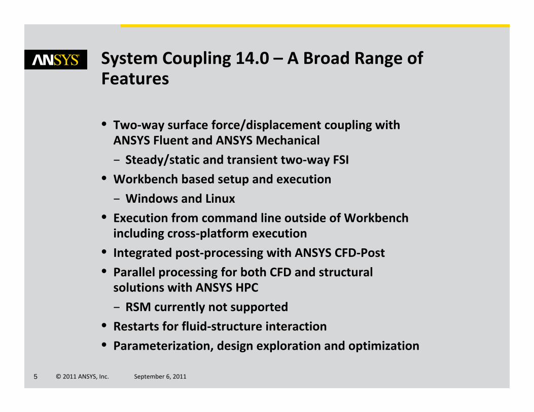
• Two‐way surface force/displacement coupling with ANSYS Fluent and ANSYS Mechanical– Steady/static and transient two‐way FSI
• Workbench based setup and execution– Windows and Linux
• Execution from command line outside of Workbench including cross‐platform execution
• Integrated post‐processing with ANSYS CFD‐Post• Parallel processing for both CFD and structural solutions with ANSYS HPC– RSM currently not supported
• Restarts for fluid‐structure interaction• Parameterization, design exploration and optimization
System Coupling 14.0 – A Broad Range of Features
© 2011 ANSYS, Inc. September 6, 20116
System Coupling Schematic Setup
© 2011 ANSYS, Inc. September 6, 20117
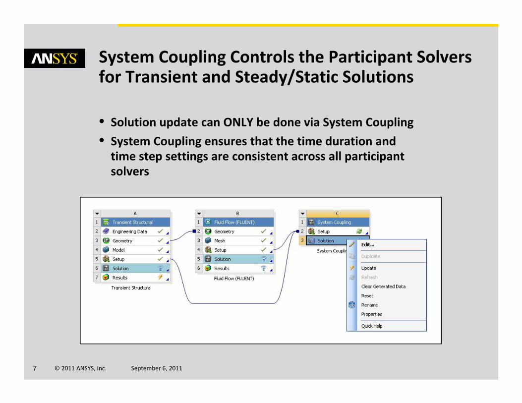
• Solution update can ONLY be done via System Coupling• System Coupling ensures that the time duration and time step settings are consistent across all participant solvers
System Coupling Controls the Participant Solvers for Transient and Steady/Static Solutions
© 2011 ANSYS, Inc. September 6, 20118
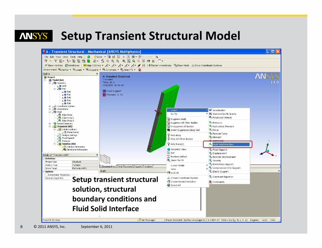
Setup Transient Structural Model
Setup transient structural solution, structural boundary conditions and Fluid Solid Interface
© 2011 ANSYS, Inc. September 6, 20119
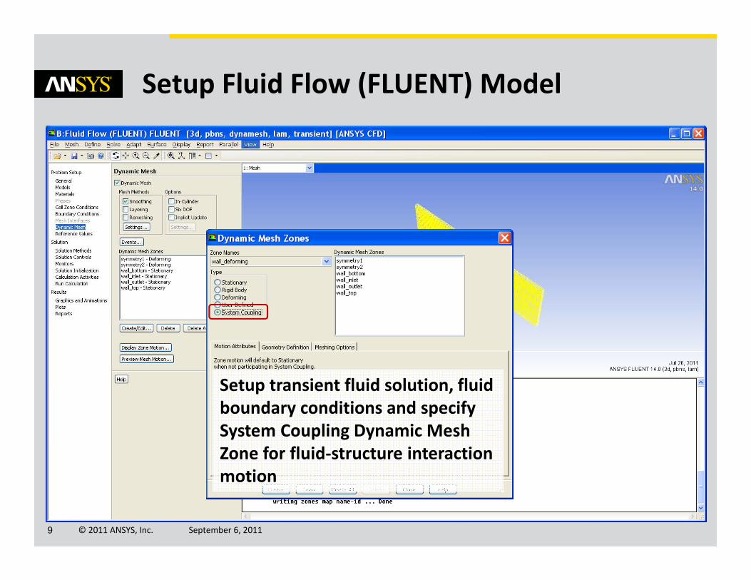
Setup Fluid Flow (FLUENT) Model
Setup transient fluid solution, fluid boundary conditions and specify System Coupling Dynamic Mesh Zone for fluid‐structure interaction motion
© 2011 ANSYS, Inc. September 6, 201110
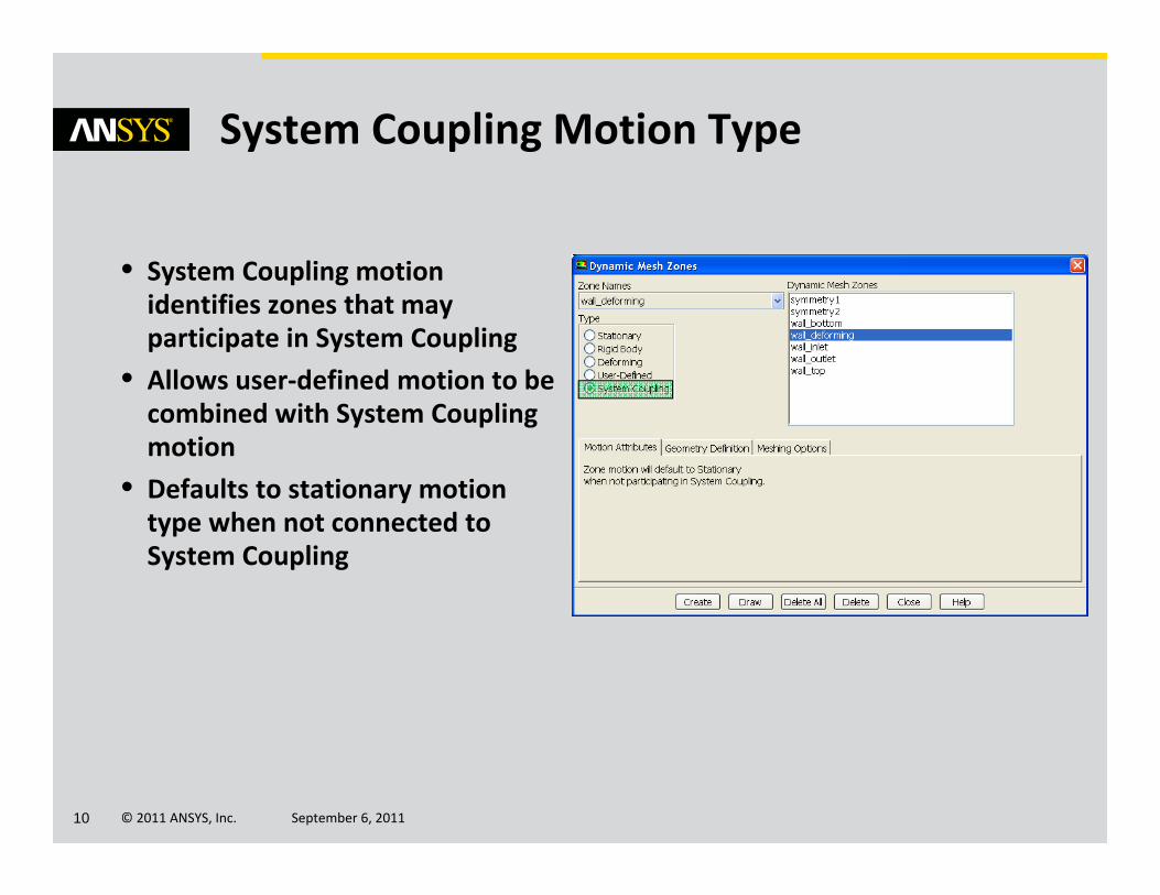
• System Coupling motion identifies zones that may participate in System Coupling
• Allows user‐defined motion to be combined with System Coupling motion
• Defaults to stationary motion type when not connected to System Coupling
System Coupling Motion Type

© 2011 ANSYS, Inc. September 6, 201111
• State of System Coupling setup cell will be– Upstream data is now available for SC Setup
Update Setup Cells for Transient Structural and Fluid Flow (FLUENT)
© 2011 ANSYS, Inc. September 6, 201112
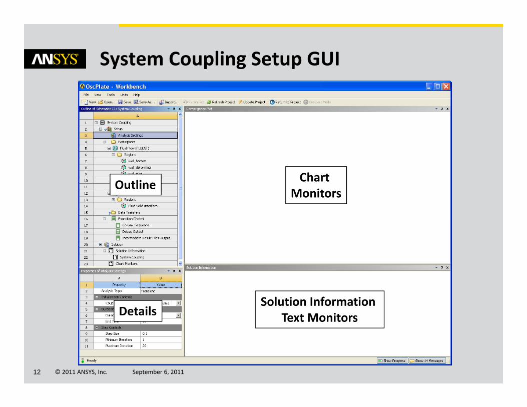
System Coupling Setup GUI
Solution Information Text Monitors
Chart Monitors
Outline
Details

© 2011 ANSYS, Inc. September 6, 201113
• Coupling End Time• Coupling Step Size• Minimum Number of Iterations per Coupling Step
• Maximum Number of Iterations per Coupling Step
System Coupling Analysis Settings
© 2011 ANSYS, Inc. September 6, 201114
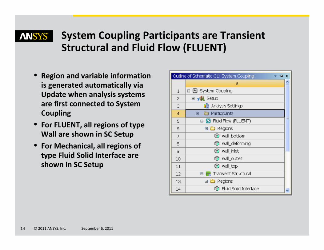
• Region and variable information is generated automatically via Update when analysis systems are first connected to System Coupling
• For FLUENT, all regions of type Wall are shown in SC Setup
• For Mechanical, all regions of type Fluid Solid Interface are shown in SC Setup
System Coupling Participants are Transient Structural and Fluid Flow (FLUENT)

© 2011 ANSYS, Inc. September 6, 201115
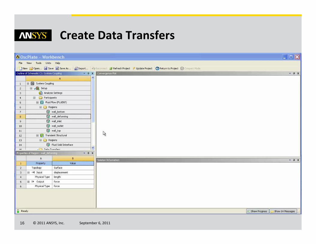
• Use Ctrl key to select a FLUENT and Mechanical region pair and select Create Data Transfer from right‐click pop‐up menu
• Automatically fills in the details for the data transfer region
• Data transfers can be one‐way (i.e. only transfer force or only transfer displacement) or two‐way
Recommended Way to Create Data Transfer Regions
© 2011 ANSYS, Inc. September 6, 201116
Create Data Transfers
© 2011 ANSYS, Inc. September 6, 201117
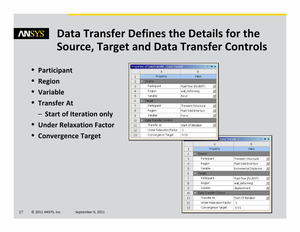
• Participant• Region• Variable• Transfer At– Start of Iteration only
• Under Relaxation Factor• Convergence Target
Data Transfer Defines the Details for the Source, Target and Data Transfer Controls
© 2011 ANSYS, Inc. September 6, 201118
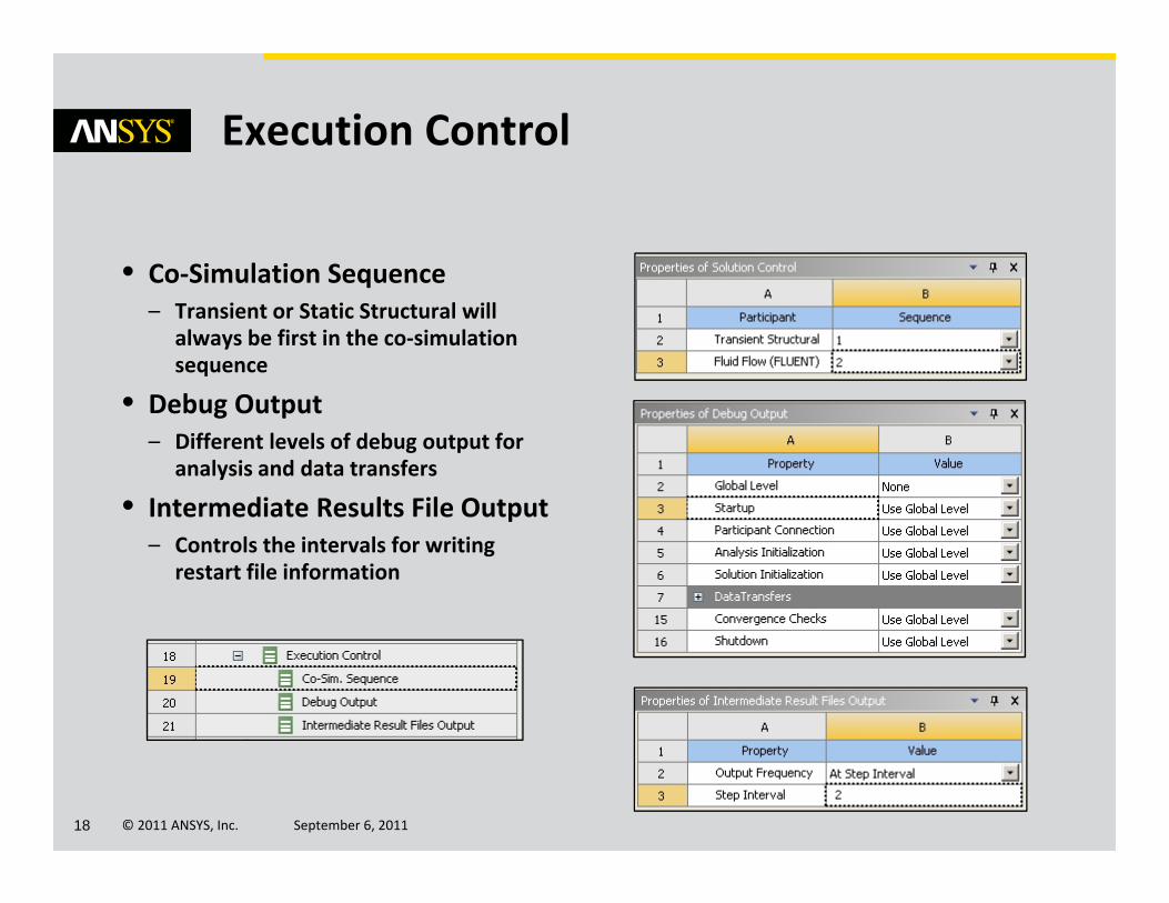
• Co‐Simulation Sequence– Transient or Static Structural will
always be first in the co‐simulation sequence
• Debug Output– Different levels of debug output for
analysis and data transfers
• Intermediate Results File Output– Controls the intervals for writing
restart file information
Execution Control

© 2011 ANSYS, Inc. September 6, 201119
Executing System Coupling
© 2011 ANSYS, Inc. September 6, 201120
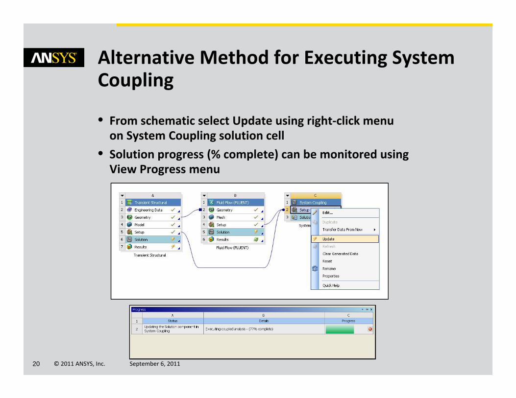
• From schematic select Update using right‐click menu on System Coupling solution cell
• Solution progress (% complete) can be monitored using View Progress menu
Alternative Method for Executing System Coupling
© 2011 ANSYS, Inc. September 6, 201121
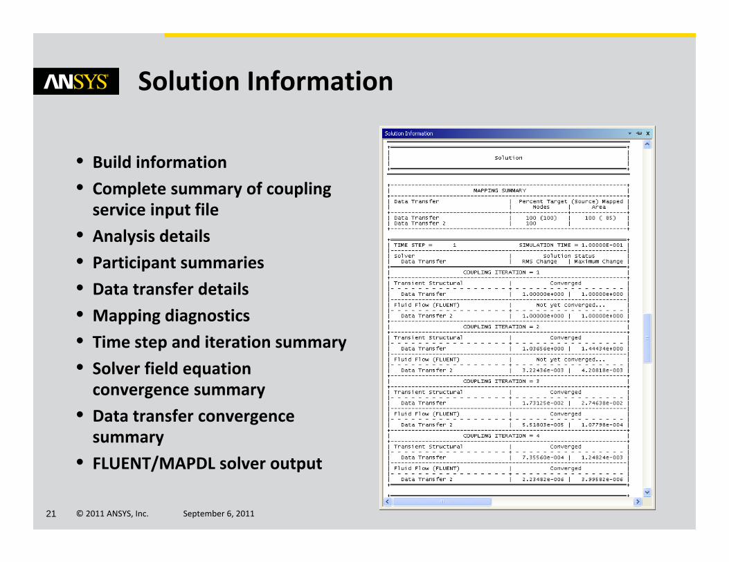
• Build information• Complete summary of coupling service input file
• Analysis details• Participant summaries• Data transfer details• Mapping diagnostics• Time step and iteration summary• Solver field equation convergence summary
• Data transfer convergence summary
• FLUENT/MAPDL solver output
Solution Information
© 2011 ANSYS, Inc. September 6, 201122
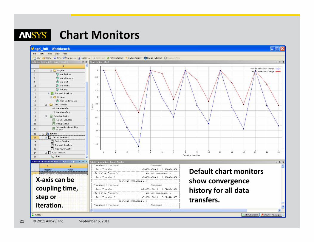
Chart Monitors
Default chart monitors show convergence history for all data transfers.
X‐axis can be coupling time, step or iteration.

© 2011 ANSYS, Inc. September 6, 201123
• Add charts by selecting Create Convergence Chart• Variables can be added or removed from charts
– Data transfers, CFD and structural convergence norms
• Chart properties are editable in same manner as other charts within ANSYS Workbench
Adding Charts and Variables
© 2011 ANSYS, Inc. September 6, 201124
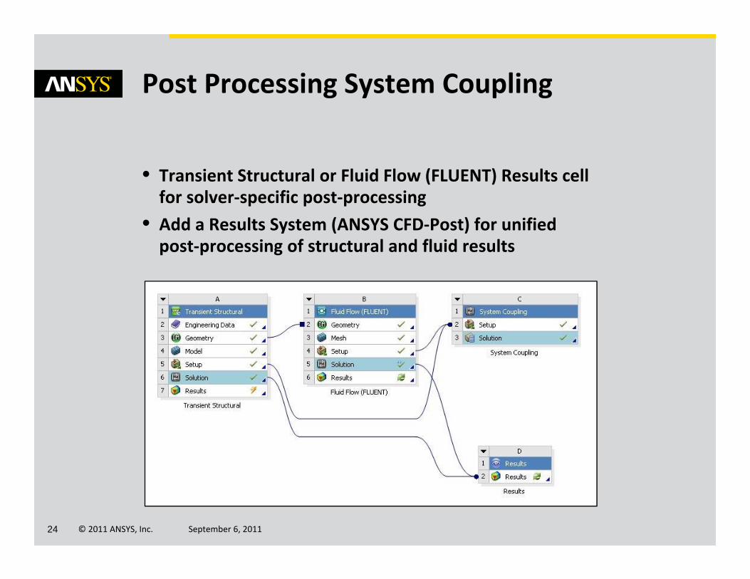
• Transient Structural or Fluid Flow (FLUENT) Results cell for solver‐specific post‐processing
• Add a Results System (ANSYS CFD‐Post) for unified post‐processing of structural and fluid results
Post Processing System Coupling
© 2011 ANSYS, Inc. September 6, 201125
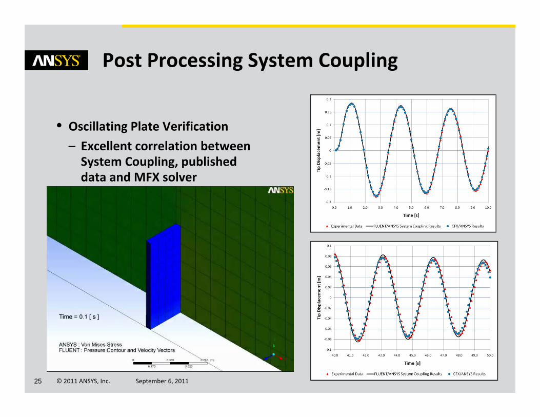
• Oscillating Plate Verification– Excellent correlation between System Coupling, published data and MFX solver
Post Processing System Coupling

© 2011 ANSYS, Inc. September 6, 201126
System Coupling – Examples
© 2011 ANSYS, Inc. September 6, 201127
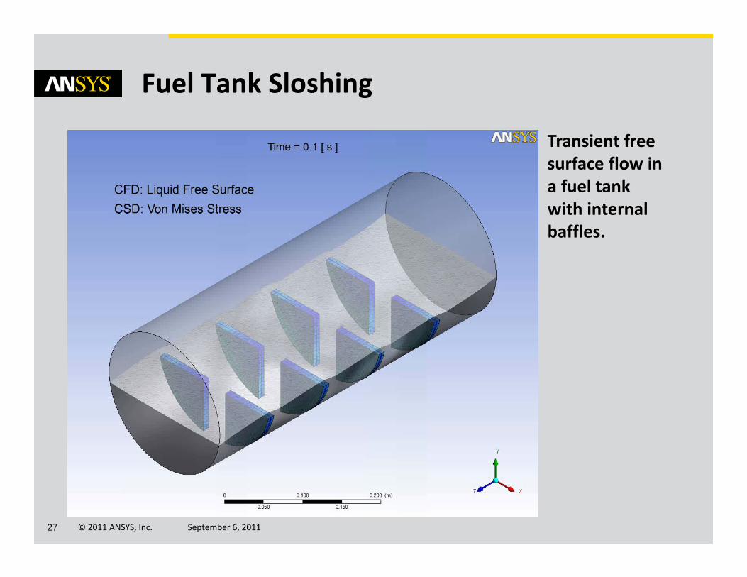
Fuel Tank Sloshing
Transient free surface flow in a fuel tank with internal baffles.
© 2011 ANSYS, Inc. September 6, 201128
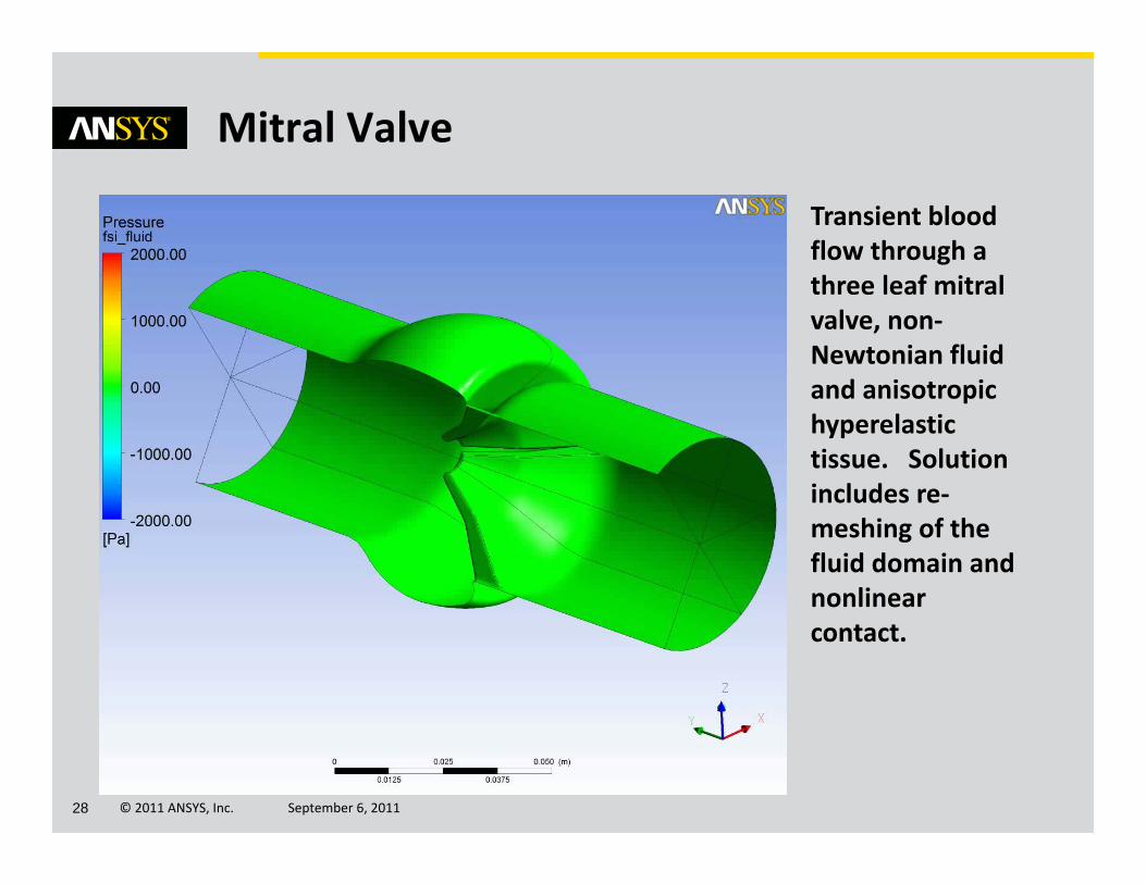
Mitral Valve
Transient blood flow through a three leaf mitral valve, non‐Newtonian fluid and anisotropic hyperelastictissue. Solution includes re‐meshing of the fluid domain and nonlinear contact.
© 2011 ANSYS, Inc. September 6, 201129
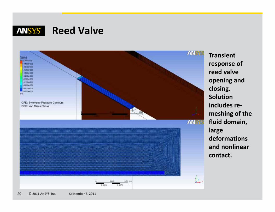
Reed Valve
Transient response of reed valve opening and closing. Solution includes re‐meshing of the fluid domain, large deformations and nonlinear contact.
© 2011 ANSYS, Inc. September 6, 201130
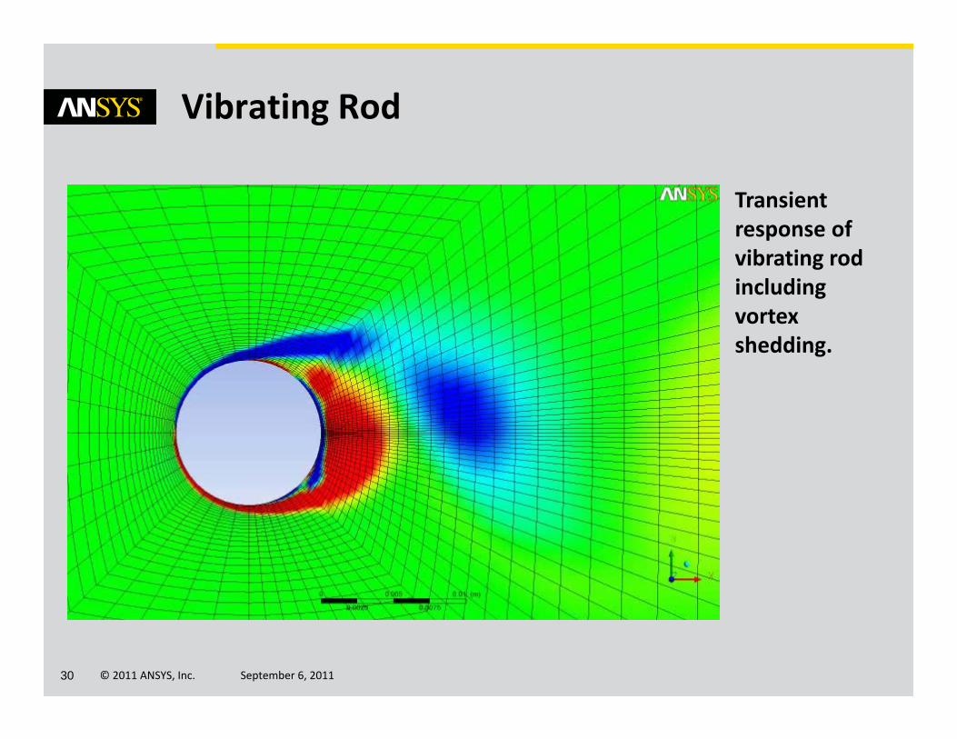
Vibrating Rod
Transient response of vibrating rod including vortex shedding.
© 2011 ANSYS, Inc. September 6, 201131
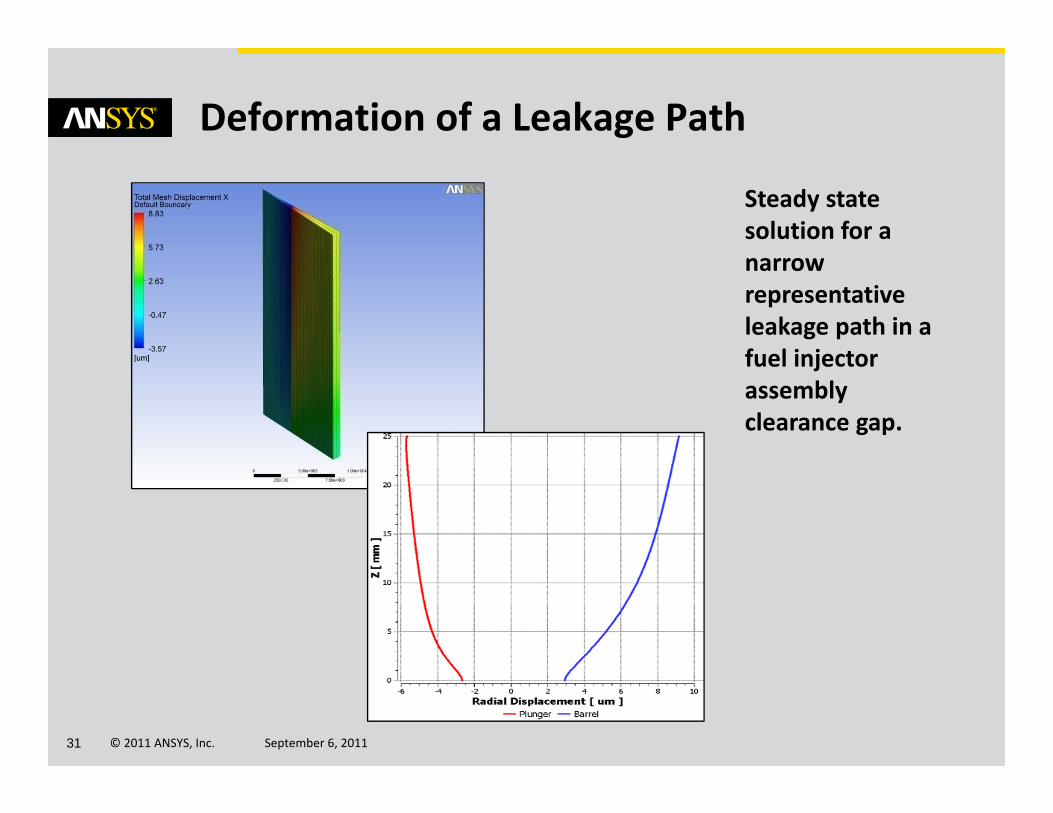
Deformation of a Leakage Path
Steady state solution for a narrow representative leakage path in a fuel injector assembly clearance gap.

© 2011 ANSYS, Inc. September 6, 201132
Questions and Answers