system compatible products for worldwide flow control€¦ · torques and technical data pneumatic...
TRANSCRIPT

Pneumatic& ElectricActuatorProductGuideSystemCompatibleProducts forWorldwideFlow Control
IntroductionAbout El-O-Matic 1
Pneumatic productsPneumatic actuators 3Special versions 6Pneumatic accessories 7BUS-communication, pneumatic actuators 9Posiflex positioners 10
Electric/electronic productsELQ Electric actuators 12BUS-communication electric actuators 14EL Electric actuators 15
Torques and technical dataPneumatic actuators 18ELQ Electric actuators 20EL Electric actuators 21
ContentsValve
automationsystems
1
va
lv
e
au
to
ma
ti
on
s
ys
te
ms
About El-O-Matic
HistoryEl-O-Matic was established in1973. Initially as a subcontractmachine shop, the company soonspecialised in the manufacture ofpneumatic actuators. The grow-ing need for process automationled to the development and pro-duction of accessories, such asswitch boxes and valve position-ers. The year 1987 saw the pro-duction of the first electric actuators.
National UnitsThe El-O-Matic world wide network was quickly established, in1978 - just five years after thecompany was founded - the firstnational unit was opened inGermany. This was followed byunits in the U.S.A (1982), UnitedKingdom and Singapore (1985),India (1990), and South Africa(1994).El-O-Matic now has an extensiveinternational network of salesoffices and distributors, providingefficient logistics and guarantee-ing world wide availability.
Emerson ElectricIn 1995 the company wasacquired by Emerson Electric, an American multinational con-glomerate consisting of morethan 300 companies and divi-sions.
Valve Automation DivisionIn 2001 Emerson Electric Co. hasannounced the formation of theValve Automation Division ofEmerson Process Management, anew operating division that con-solidates the company’s vast arrayof valve automation products andservices. The new division bringstogether well-known industryleaders Bettis Actuators andControls, El-O-Matic International,and Bettis subsidiaries HytorkInternational, Shafer ValveOperating Systems, andDantorque.
For El-O-Matic, the merger pro-vides all the resources for contin-ued expansion and growth. Ourengineering development makesregular use of the gigantic reser-voir of process-automationknowledge available withinEmerson's Industrial Automationdivisions.
Some figuresEl-O-Matic is one of the world'slargest specialised manufacturersof valve actuators. Our main pro-duction facility is located inHengelo, in the Netherlands. In addition, we have three maindistribution centres:- The Netherlands (Hengelo),
serving Europe, the Middle Eastand Africa
- USA (Tampa FL), serving North,Central and South America.
- Singapore, serving Asia and thePacific Area.
Our local service organisationsare listed on the back of thisbrochure.Since the Emerson acquisition, wehave been part of an enterprisewith a total turnover exceeding14.3 billion US-dollars (1999).
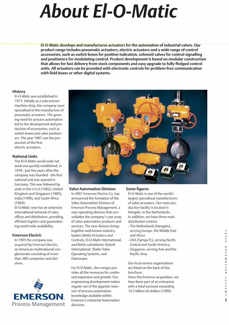
El-O-Matic develops and manufactures actuators for the automation of industrial valves. Ourproduct range includes pneumatic actuators, electric actuators and a wide range of controlaccessories, such as switch boxes for position indication, solenoid valves for control signallingand positioners for modulating control. Product development is based on modular constructionthat allows for fast delivery from stock components and easy upgrade to fully-fledged controlunits. All actuators can be provided with electronic controls for problem-free communicationwith field buses or other digital systems.
va
lv
e
au
to
ma
ti
on
s
ys
te
ms
2
PolicyThe process industry is in a con-stant state of change. The maindevelopments in recent yearshave been the application of digi-tal controls and the introductionof field-bus systems. Digital tech-nology has dramatically changedthe verification and control ofprocess events and with the two-way communication provided byfieldbus and the ability to decen-tralise many of the control func-tions means that the actual costof production is reduced. This isachieved at the same time as pro-viding systems, which are moreflexible, more accurate and lesssensitive to faults.
InnovationEl-O-Matic strives to maintain itsleadership with these new develop-ments. Though traditionally amanufacturer of actuators, ourpolicy continues to be focused onthe supply of all the automationcomponents located between thehardware of the valve and the
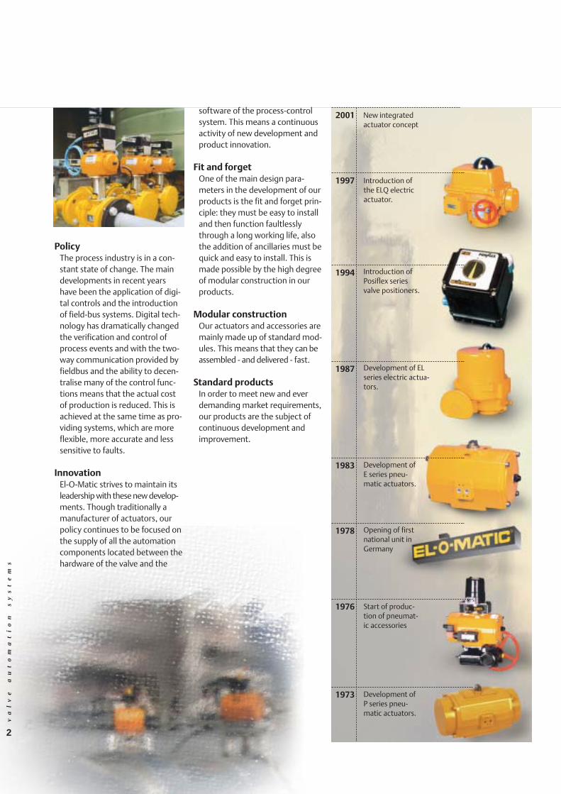
1973
1976
1978
1983
1987
1994
1997
Development of P series pneu-matic actuators.
Start of produc-tion of pneumat-ic accessories
Opening of firstnational unit inGermany
Development of E series pneu-matic actuators.
Development of ELseries electric actua-tors.
Introduction ofPosiflex seriesvalve positioners.
Introduction ofthe ELQ electricactuator.
2001 New integrated actuator concept
software of the process-controlsystem. This means a continuousactivity of new development andproduct innovation.
Fit and forgetOne of the main design para-meters in the development of ourproducts is the fit and forget prin-ciple: they must be easy to installand then function faultlesslythrough a long working life, alsothe addition of ancillaries must bequick and easy to install. This ismade possible by the high degreeof modular construction in ourproducts.
Modular constructionOur actuators and accessories aremainly made up of standard mod-ules. This means that they can beassembled - and delivered - fast.
Standard productsIn order to meet new and everdemanding market requirements,our products are the subject ofcontinuous development andimprovement.

af
sl
ui
te
ra
ut
om
at
is
er
in
gs
ys
te
me
nv
al
ve
a
ut
om
at
io
n
sy
st
em
s
&3
Accessories
PneumaticActuators
Pneumatic actuators are required to operatein a wide variety of applications; they have tofunction first time every time, often undervery difficult circumstances. One actuatormay perform hundreds of cycles 24 hours aday, whereas another may open and close justonce a month - then may stay open formonths on end, but still be ready to shutdown instantly on a failure signal.The extremes of temperature, harsh duty andcorrosive atmospheres where actuators areoften applied demand the highest attentionto the quality of design and manufacture.

va
lv
e
au
to
ma
ti
on
s
ys
te
ms
4
and pinion construction meansthat actuators are lightweight andoccupy a minimum of space.
Ample choice of spring packages
Spring return, single acting actuators are used in most safetysystems. Their ability to automati-cally return the valve to its fail-safe position on air failure pro-vides the vital link for ultimatesystem shut down. El-O-Maticspring return actuators havemodular spring packages, which
Optimum performanceWe realise that the performance ofour pneumatic actuators is vitallyimportant to your productionprocess. An actuator that does notfunction well often has seriousconsequences for the outcome ofthe process. That is why qualityhas been our primary concept inactuator development. El-O-Maticpneumatic actuators are reliable,quality products, continuouslyproviding optimum performanceunder all circumstances.
Standard Specification• Pressure 0.2 to 8 bar
• Temperature -20°C to +80°C
• Materials Housing: Aluminium alloy
Shaft: Hard anodised
aluminium alloy
• Finish Polyester non-TGIC based
powder coating
• Lifespan Minimum of 500,000 cycles
Features• For application to ball, plug and
butterfly valves.• Can be used in other quarter-
turn applications, such asdampers and pressure regulators.
• Actuators are made of highduty aluminium alloys, provid-ing optimum strength and corrosion resistance.
• Compact rack & pinion design.• Can be supplied in single
(spring return) or double acting versions.
• Choice of twelve sizes, with a torque range from 12 to4000 Nm.
• Mounting for solenoid valvesand position signallers to theNAMUR standard (VDI/VDE3845).
• Valve mounting and drivedimensions to the ISO 5211or DIN 3337
• Drive shaft provided withinsert, for low cost, versatiledirect valve mountings.
• Anti-blow-out shaft.
Operating principlePneumatic actuators come in twoversions: double acting and singleacting (spring return). Both ver-sions are designed in such a waythat (with the exception of theposition indicator) there are nomoving parts on the outside. Thismakes them safe, easy to installand virtually maintenance free.Furthermore, the compact rack
Pneumaticactuators
enable them to beeasily applied to awide varietyof supplypressures andoperating conditions.
5
va
lv
e
au
to
ma
ti
on
s
ys
te
ms
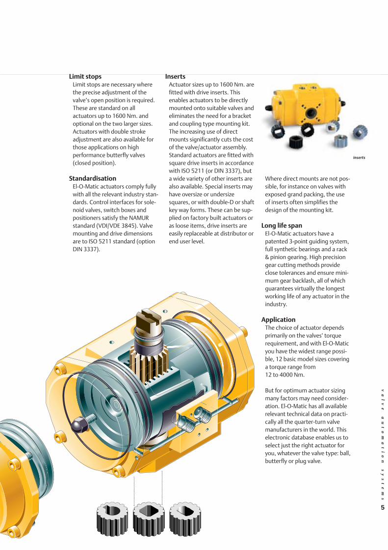
inserts
Where direct mounts are not pos-sible, for instance on valves withexposed grand packing, the useof inserts often simplifies thedesign of the mounting kit.
Long life spanEl-O-Matic actuators have apatented 3-point guiding system,full synthetic bearings and a rack& pinion gearing. High precisiongear cutting methods provideclose tolerances and ensure mini-mum gear backlash, all of whichguarantees virtually the longestworking life of any actuator in theindustry.
ApplicationThe choice of actuator dependsprimarily on the valves’ torquerequirement, and with El-O-Maticyou have the widest range possi-ble, 12 basic model sizes coveringa torque range from 12 to 4000 Nm.
But for optimum actuator sizingmany factors may need consider-ation. El-O-Matic has all availablerelevant technical data on practi-cally all the quarter-turn valvemanufacturers in the world. Thiselectronic database enables us toselect just the right actuator foryou, whatever the valve type: ball,butterfly or plug valve.
Limit stopsLimit stops are necessary wherethe precise adjustment of thevalve’s open position is required.These are standard on all actuators up to 1600 Nm. andoptional on the two larger sizes.Actuators with double strokeadjustment are also available forthose applications on high performance butterfly valves(closed position).
StandardisationEl-O-Matic actuators comply fullywith all the relevant industry stan-dards. Control interfaces for sole-noid valves, switch boxes andpositioners satisfy the NAMURstandard (VDI/VDE 3845). Valvemounting and drive dimensionsare to ISO 5211 standard (optionDIN 3337).
InsertsActuator sizes up to 1600 Nm. arefitted with drive inserts. Thisenables actuators to be directlymounted onto suitable valves andeliminates the need for a bracketand coupling type mounting kit.The increasing use of directmounts significantly cuts the costof the valve/actuator assembly.Standard actuators are fitted withsquare drive inserts in accordancewith ISO 5211 (or DIN 3337), buta wide variety of other inserts arealso available. Special inserts mayhave oversize or undersizesquares, or with double-D or shaftkey way forms. These can be sup-plied on factory built actuators oras loose items, drive inserts areeasily replaceable at distributor orend user level.

6
va
lv
e
au
to
ma
ti
on
s
ys
te
ms
Pneumaticactuator
Special versionsSpecial actuators can be built tosuit a wide variety of extremeapplications: high temperature,low temperature, offshore, firesafe, with different operatingmedia, etc.
Ask our technical specialists formore information about thesespecial applications.

7
Specifications of standard switch boxesHHDDNN LLDDNN
•• SSwwiittcchheess Type V3, mechanicalVoltage 250 V AC or DCContacts normally open and normally closed,
single-pole toggle switchesCurrent at 250 V AC 10 A 11 ACurrent at 250 V DC 1/4 A 1/4 ACurrent at 12 V DC 6 A 1 ATemperature -20 °C to +80°C -25 °C to +80°C
•• HHoouussiinngg Material Aluminium alloy Base: ABS (black)Cover: ABS (transp.)
Protection category IP 67 (IEC 529) IP 65 (IEC 529)Finish epoxy coatingMounting VDI/VDE 3845 NAMUR
HDN (left) and LDN switchboxes.
va
lv
e
au
to
ma
ti
on
s
ys
te
ms
Solenoid valveSolenoid valves provide localopen/close control by means of aremote powered electric signal. El-O-Matic supplies industry standardNAMUR solenoid valves for directmounting on the air connectionface of the actuator. These arespring return solenoid valves. On
Pneumaticaccessories
Position indicationFor effective valve control, the con-troller needs to know the open/closed state of the valve. The El-O-Matic switch box range provides forevery possible requirement for posi-tion indication. In addition to thebasic versions described below, El-O-Matic supplies 2- or 3-wire prox-imity switches, reed switches andswitches for specific explosion-safeapplications.
HDN switch boxA heavy-duty (Aluminium alloy)switch box contains a pair of contactmicro switches activated by twocams on a shaft driven by the actua-tor. These signal the full open andclosed valve position. Both switchesare independently adjustable andterminals are provided for the sys-tem’s connection. The switch box isof generous proportions and hastwo electrical entries so that, withadditional terminals, the connectionto the actuator’s solenoid valve maybe back wired to provide the userwith a single connection point.
HDN switch boxes can be suppliedas waterproof executions (IP 67 toIEC 529) and explosion proof executions like EEx d or EEx i (ATEXcertified), or Class l, Div. 1 group C,D. Class II, Div. 1 group E, F, G.(CSA certified).
LDN switch boxThis switch box is suitable for utili-ty applications or process applica-tions under conditions that areless demanding. Functionality issimilar to that of the HDN but witha lower level of waterproofing (IP65) and limited explosion proofversions.
The basic actuator may be used to open and close the valve,but if more functionality is required then the actuators’ speci-fication can be extended by the addition of one or more of theavailable accessories. These can be used to make the actuatoroperate faster or slower or to provide position signalling feed-back to the controller or to provide positional control. Theseare just a small sample of the countless additional possibilitiesprovided by El-O-Matic pneumatic accessories. The range isextensive and is being added to all the time.
power failure auto-matically returningthe actuator to apre-set (normallyclosed) position. Solenoid valves areof the universal typeand may be used on double actingor single acting actuators; thechange is made by means of areversible manifold plate. Standardsolenoid valves are provided with amanual override control. As anoption, speed control restricters areavailable fitted at the exhaust ports.

8
Manual Override controlThe El-O-Matic MO Seriesdeclutchable gear operators offer asimple and reliable method oflocal manual operation, this maybe required during commissioningset up, as emergency control on airfailure, or as a local control in theevent of controller malfunction. Assuch when the hand wheel isclutched in, the valve is under localmanual control and the remotecontrol is "locked out".
Specifications of Manual Override gearbox
• Housing: Cast Aluminium• Drive: Worm/worm wheel• Worm wheel: Bronze• Temperature: -20°C to + 80°C• Stroke limitation: +/- 5°• Finish: 2-component
polyurethane coating
Speed Control plateThis is used in combination with aNAMUR solenoid valve and servesto provide independent speedcontrol of both the opening andclosing strokes. The speed controlplate can be used with both singleand double acting actuators, butwhen used on single acting actua-tors, only the spring return strokeis regulated.
Breather BlockThe breather block is used on sin-gle acting actuators and providescorrosion protection of the actua-tor spring chamber. It should beused on applications where theactuator is located in a corrosiveatmosphere that would otherwisebe sucked into the actuator duringthe spring stroke.The breather block is fixed directlyonto the actuators NAMUR airentry manifold and has a furtherNAMUR interface so that a suitablesolenoid valve may be directlymounted, or for a tubing connec-tion in the case of a remote sole-noid valve.
The breather block has a built-inquick exhaust function to improvethe spring stroke time. An optionalspeed control can be provided toregulate this closing time.
Block & Vent valveThis should be used on applica-tions where on site servicing of theactuator is required and where theactuator needs to be isolated fromthe control system. It provides alocal means of blocking the supplyair from the actuator at the sametime venting all compressed airfrom both chambers of the actua-tor. It may be used for double act-ing or spring return actuators.The valve block is fixed directlyonto the NAMUR air entry mani-fold and has a further NAMURinterface so that a suitable sole-noid valve may be directly mount-ed.
Specifications of Breather Block and Block & Vent valveBBrreeaatthheerr BBlloocckk BBlloocckk && VVeenntt vvaallvvee
• housing Aluminium alloy Aluminium alloy• Finish Hard anodised Anodised
PTFE impregnated• Pressure 1 to 10 bar up to 10 bar• Temperature -20 to +80°C -20 to +80°C• Air inlet G 1/4" G 1/4"• Air outlet G 3/8" G 3/8"• Air flow (Kv) air stroke: 0.8 m3/h 0.8 m3/h
spring stroke: 1.9 m3/h 0.8 m3/h• Media air, dry or corrosion-free gas air, dry or corrosion-free gas
(not suitable for oxygen) (not suitable for oxygen)• Option lock
Pneumaticaccessories
va
lv
e
au
to
ma
ti
on
s
ys
te
ms
Specifications of solenoid valve• Type: 5/2 - 3/2
(convertible)• Pressure: 1 to 10 bar• Lubrication: Not necessar• Temperature: -20 to +60°C
(depending on version)
• Voltage: 220 V AC/50 Hz or24 V DC standard,other voltages onrequest
• Duty: Continuous• Protection IP65, Explosion
class: proof on request
Manual Override control
Breather Block Block & Vent valve
9
Pneumaticaccessories
BUS communication
The LDN switchbox is availablewith ASI (actuator sensor inter-face), the HD box with ASI andProfibus-DP or PA. All have basicfunctionality of two-way commu-nication, the fieldbus controllerreceiving input from the two posi-tion indicating switches (mechani-cally adjustable 0-90º), and anoutput to the solenoid valve(s)which may be to mono-stable orbi-stable. Bus wiring may be 2wire or 4 wire depending on thesystem.
AS interface in LDN box
AS interface in HD box
va
lv
e
au
to
ma
ti
on
s
ys
te
ms
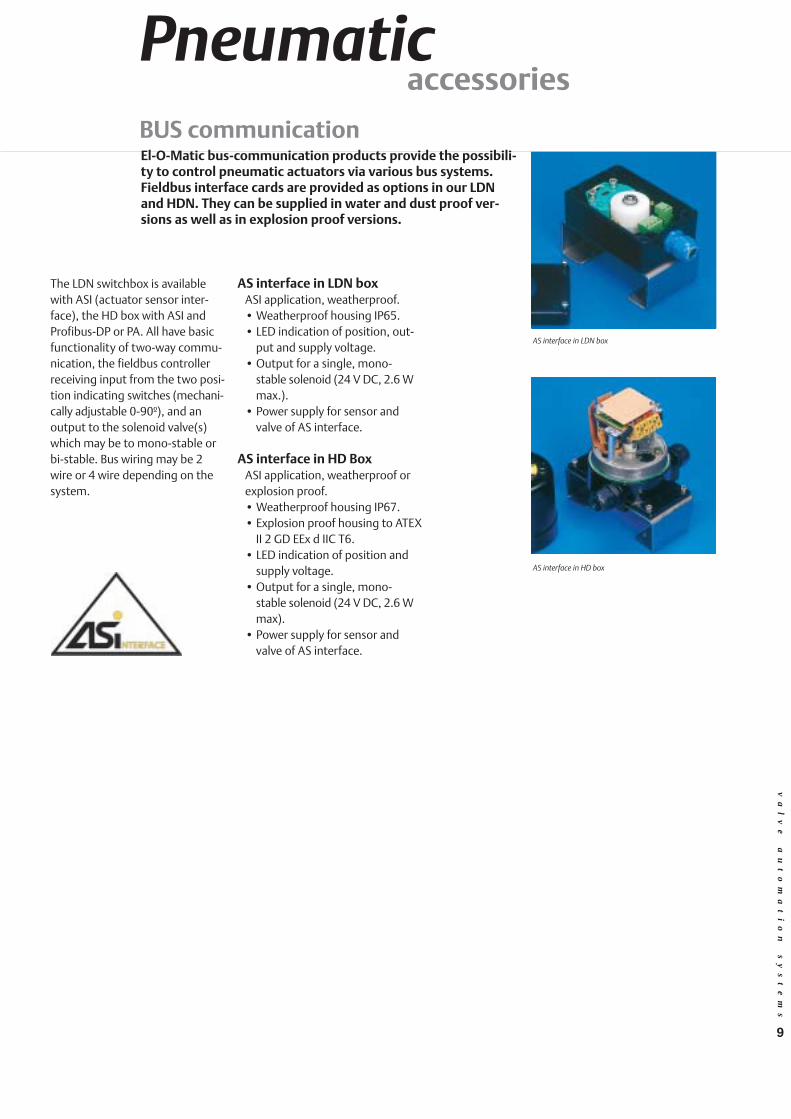
El-O-Matic bus-communication products provide the possibili-ty to control pneumatic actuators via various bus systems.Fieldbus interface cards are provided as options in our LDNand HDN. They can be supplied in water and dust proof ver-sions as well as in explosion proof versions.
AS interface in LDN boxASI application, weatherproof. • Weatherproof housing IP65.• LED indication of position, out-
put and supply voltage.• Output for a single, mono-
stable solenoid (24 V DC, 2.6 Wmax.).
• Power supply for sensor andvalve of AS interface.
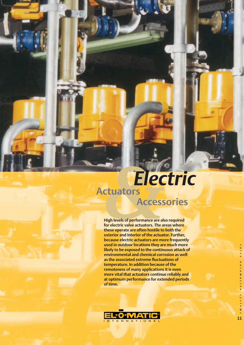
AS interface in HD BoxASI application, weatherproof orexplosion proof.• Weatherproof housing IP67.• Explosion proof housing to ATEX
II 2 GD EEx d IIC T6.• LED indication of position and
supply voltage.• Output for a single, mono-
stable solenoid (24 V DC, 2.6 Wmax).
• Power supply for sensor andvalve of AS interface.

10
va
lv
e
au
to
ma
ti
on
s
ys
te
ms
Pneumaticaccessories
Posiflex positionersPositioners are instruments that play a vital part in the process.They must convert the incoming control signal quickly and effi-ciently and respond by regulating the valve to a precise posi-tion between 0 and 100%. The El-O-Matic "Posiflex" positionersare high quality, reliable instruments that form a strong link inmodern process control systems.
Posiflex positionersThe Posiflex range consists of 2models, the pneumatic F10 andthe electro-pneumatic F20. Bothmodels are used in applications inwhich the pneumatic actuatorsmust be positioned with a highdegree of accuracy. The position-ers are suitable for both single anddouble-acting . They can also beused for controling other move-ments. All Posiflex positioners arerobust, with housings of cast alu-minium alloy with a finish of pow-der coating. They are highly resist-ant to external corrosion. The inte-rior has a modular structure sothat it can be simply adapted toyour specific uses. The variousaccessories are described on thispage.
AccessoriesGG 11 aanndd GG22 ggaauuggee bblloocckkss • Type G1 is suitable for the
Posiflex F10 and gives the actuator’s operating pressureand the incoming instrumentpressure.
• Type G2 is suitable for thePosiflex F20. It provides an indi-cation of the output and incom-ing air pressure.
PPoossiittiioonn ttrraannssmmiitttteerrss PPTTFF2200,, PPTT22 These electronic position transmit-ters transmit a continuous 4 to 20 mA feedback signal, thisreflects the mechanical position ofthe positioner. These positiontransmitters are also available inan intrinsically safe EEx i execution.• The PTF20 is available as a "Plug-
in" option for the F20 positioner.• The PT2 is available as a "build in"
module for F10 and F20 posi-tioners.
PPoossiittiioonn iinnddiiccaattoorrss• PNP, 3-wire inductive switches• IS2, 2-wire inductive switches.
This Intrinsically Safe variationmay be used as part of anIntrinsically Safe system in anexplosion hazardous area.
• S2, mechanical end of stroke V3switches.
• POT, Potentiometer for a contin-uous resistive feedback signal ofthe valve position.
Features valve positionersGGeenneerraall
• Provides the ultimate in quickand accurate positioning.
• Suitable for single acting (springreturn) and double acting actuators.
• High-grade aluminium alloyhousing finished with an epoxycoating.
• Direct and reverse acting.• Standard mounting to VDI/VDE
3845 (NAMUR).• Modular structure, therefore
easy expansion possibilities.• Suitable for controlling rotary
actuators and other devices.
FF1100• Pneumatic positioner.• Simple robust model. • Only mechanical parts. • External zero-setting. • Hose down proof.
FF2200• Electro-pneumatic positioner.• Analogue electric signal
(4-20 mA).• Split-range and reverse-acting
setting functions simplyadjustable by jumpers.
• Intrinsically safe II 2 G EEx ib llCT6 option.
• Enclosure IP65.
Gauge block
F20 electro-pneumatic positioner
af
sl
ui
te
ra
ut
om
at
is
er
in
gs
ys
te
me
nv
al
ve
a
ut
om
at
io
n
sy
st
em
s
&Accessories
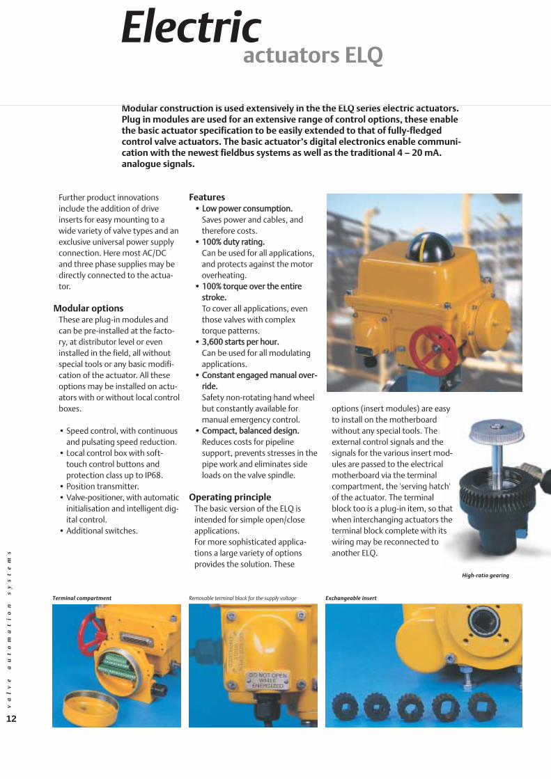
High levels of performance are also requiredfor electric valve actuators. The areas wherethese operate are often hostile to both theexterior and interior of the actuator. Further,because electric actuators are more frequentlyused in outdoor locations they are much morelikely to be exposed to the continuous attack ofenvironmental and chemical corrosion as wellas the associated extreme fluctuations of temperature. In addition because of theremoteness of many applications it is evenmore vital that actuators continue reliably andat optimum performance for extended periodsof time.
ElectricActuators
11
12
va
lv
e
au
to
ma
ti
on
s
ys
te
ms
Electricactuators ELQ
Further product innovationsinclude the addition of driveinserts for easy mounting to awide variety of valve types and anexclusive universal power supplyconnection. Here most AC/DCand three phase supplies may bedirectly connected to the actua-tor.
Modular optionsThese are plug-in modules andcan be pre-installed at the facto-ry, at distributor level or eveninstalled in the field, all withoutspecial tools or any basic modifi-cation of the actuator. All theseoptions may be installed on actu-ators with or without local controlboxes.
• Speed control, with continuousand pulsating speed reduction.
• Local control box with soft-touch control buttons and protection class up to IP68.
• Position transmitter.• Valve-positioner, with automatic
initialisation and intelligent dig-ital control.
• Additional switches.
options (insert modules) are easyto install on the motherboardwithout any special tools. Theexternal control signals and thesignals for the various insert mod-ules are passed to the electricalmotherboard via the terminalcompartment, the 'serving hatch'of the actuator. The terminalblock too is a plug-in item, so thatwhen interchanging actuators theterminal block complete with itswiring may be reconnected toanother ELQ.
Terminal compartment
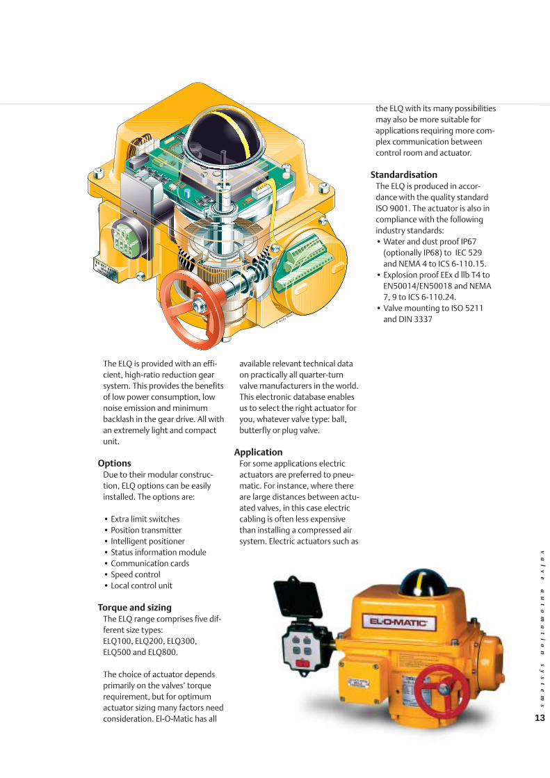
High-ratio gearing
Removable terminal block for the supply voltage Exchangeable insert
Modular construction is used extensively in the the ELQ series electric actuators.Plug in modules are used for an extensive range of control options, these enablethe basic actuator specification to be easily extended to that of fully-fledgedcontrol valve actuators. The basic actuator’s digital electronics enable communi-cation with the newest fieldbus systems as well as the traditional 4 – 20 mA.analogue signals.
Features•• LLooww ppoowweerr ccoonnssuummppttiioonn..
Saves power and cables, andtherefore costs.
•• 110000%% dduuttyy rraattiinngg..Can be used for all applications,and protects against the motoroverheating.
•• 110000%% ttoorrqquuee oovveerr tthhee eennttiirreessttrrookkee..To cover all applications, eventhose valves with complextorque patterns.
•• 33,,660000 ssttaarrttss ppeerr hhoouurr..Can be used for all modulatingapplications.
•• CCoonnssttaanntt eennggaaggeedd mmaannuuaall oovveerr--rriiddee..Safety non-rotating hand wheelbut constantly available formanual emergency control.
•• CCoommppaacctt,, bbaallaanncceedd ddeessiiggnn..Reduces costs for pipeline support, prevents stresses in thepipe work and eliminates sideloads on the valve spindle.
Operating principleThe basic version of the ELQ isintended for simple open/closeapplications. For more sophisticated applica-tions a large variety of optionsprovides the solution. These
13
va
lv
e
au
to
ma
ti
on
s
ys
te
ms
The ELQ is provided with an effi-cient, high-ratio reduction gearsystem. This provides the benefitsof low power consumption, lownoise emission and minimumbacklash in the gear drive. All withan extremely light and compactunit.
OptionsDue to their modular construc-tion, ELQ options can be easilyinstalled. The options are:
• Extra limit switches• Position transmitter• Intelligent positioner• Status information module• Communication cards• Speed control• Local control unit
Torque and sizingThe ELQ range comprises five dif-ferent size types:ELQ100, ELQ200, ELQ300,ELQ500 and ELQ800.
The choice of actuator dependsprimarily on the valves’ torquerequirement, but for optimumactuator sizing many factors needconsideration. El-O-Matic has all
available relevant technical dataon practically all quarter-turnvalve manufacturers in the world.This electronic database enablesus to select the right actuator foryou, whatever valve type: ball,butterfly or plug valve.
ApplicationFor some applications electricactuators are preferred to pneu-matic. For instance, where thereare large distances between actu-ated valves, in this case electriccabling is often less expensivethan installing a compressed airsystem. Electric actuators such as
the ELQ with its many possibilitiesmay also be more suitable forapplications requiring more com-plex communication betweencontrol room and actuator.
StandardisationThe ELQ is produced in accor-dance with the quality standardISO 9001. The actuator is also incompliance with the followingindustry standards:• Water and dust proof IP67
(optionally IP68) to IEC 529and NEMA 4 to ICS 6-110.15.
• Explosion proof EEx d llb T4 toEN50014/EN50018 and NEMA7, 9 to ICS 6-110.24.
• Valve mounting to ISO 5211and DIN 3337

14
Electricactuators ELQ
BUS communication
va
lv
e
au
to
ma
ti
on
s
ys
te
ms
Q-CFF/Q-CDPS/Q-CPAS optionWith this ELQ option, El-O-Maticprovides an electric actuator withFieldbus FoundationTM orProfibus®-DP/PA digital field-buscommunication. Using these field-bus options, the input and outputsignals of the actuator can be sentvia a two-wire connection andconnected to the control systemvia a fieldbus network.For Fieldbus FoundationTM andProfibus®-DP or PA, three versionlevels are available for 'open/close'and 'modulating' applications.
''OOppeenn//cclloossee'' vveerrssiioonnss::- A maximum of four digital out-
puts (DO) and two analogueinputs (AI) available.
- Possibility to activate or deacti-vate the bus communication
and open/close the actuator byconventional means.
- Standard feedback of stroke endposition, signals foropening/closing, over torque ormotor-switch faults.
- Feedback of actuator tempera-ture, run torque, maximumtorque, heater element on/off,stroke position and when thelocal control unit is used.
- Read-out possibility of variousidentification items.
MMoodduullaattiinngg vveerrssiioonnss::In addition versions fitted withthe modulating positioner havethe following reset functions:- Remote initialisation of actuator
via bus.- Maximum of three analog inputs
(AI) available.
- Standard digital adjustableSensitivity/Deadband.
- Digital adjustments possible forzero range, high and low signal,action, response curve: Linear,equal percentage or quick open-ing.
- Custom curve: the ability tomodify the equal percentage orquick opening curves.
- 20-point curve: The responsecurve can be freely modifiedbased on a 20-point co-ordinategrid.
QQ--AASSII ooppttiioonnThis ELQ option makes it possibleto open and close the actuator bymeans of the 2-wire AS interfacebus system and get feedbackfrom the stroke end positions. - Discrete bus communication.- No external supply voltage nec-
essary for I/O cards.- Explosion proof versions
applicable in zones 1 and 2.- LED indication of position and
supply voltage.
El-O-Matic has developed various options for the ELQ actuators in order toallow for control via the various bus systems. Communication with these bussystems is handled by means of electronics partially incorporated in an expan-sion box mounted on the side of the ELQ. Because the ELQ uses digital elec-tronics for basic control within the actuator it can easily handle bus type com-munications of most types from the relatively simple systems, such as ASI(actuator sensor interface) to the more complex systems such as FieldbusFoundationTM, Profibus®-DP and Profibus®-PA.

15
Electricactuators EL
FeaturesStandard versions are providedwith mechanical end stops, limitswitches for open/close indicationand anti-condensation heater.Corrosion resistant materials used throughout:Aluminium housing, stainlesssteel fastenings and hard-bronzegear transmission.Also:• Can be applied to all ball, plug
and butterfly valves.• Low-noise, smooth running by
the use of high ratio worm andwheel reduction.
• Compact construction andlightweight due to the use ofhigh-grade aluminium alloys
• Corrosion protected by the useof the external coating (2-com-ponent polyurethane).
• Wide range of voltage options.
• Self-locking reduction gear withminimum backlash in the trans-mission.
• Visualposition indicator.• Mountings in accordance with
the ISO 5211or DIN 3337 stan-dard.
ELS, EL and ELD electric actuator series
Our range of electrical actuatorscomprises the ELS, EL and ELDseries. The series covers thetorque range from 18 to 2500Nm. The ELS series is an econom-ic choice for application on fit-tings with a small passage area.The ELD series is designed forheavier applications and is provid-ed with a declutchable manualoverride emergency control.
As market leader in actuators, we realise that the consistenthigh quality of our products is of crucial importance to yourproduction process. That’s why our development activitiesfocus on quality. You'll find this reflected by the performance ofour actuators, and in our choice of such materials as high quali-ty aluminium alloys, stainless steel and bronze. El-O-Matic elec-tric actuators are reliable quality products, which can be reliedon to perform faultlessly no matter how demanding the circum-stances.
va
lv
e
au
to
ma
ti
on
s
ys
te
ms
StandardsThe ELS, EL and ELD series areproduced in accordance with thequality standard ISO 9001. Theactuators, depending on modelsize, are also in compliance withthe following industry standards:• ISO 5211, EN 55014• DIN 3337, EN 50082-2• EN 50014, EN 50018,
EN 50093• EN 60204, EN 60529
Operating principleAll actuators in these series aretotally self enclosed and havethermal switches in the motorwindings to prevent motors fromoverheating. Standardised con-nection flanges are used for sim-ple installation on all quarter turnvalves, such as ball, plug and but-terfly valves. ELS actuators are the economicchoice for small valves in thetorque range of 18 to 25 Nm. Thebasic AC or DC motors providetorque by means of a set of spurreduction gears.EL actuators cover the middlerange of torques from 55 to 800Nm. They have worm/wormwheel reduction gearing andhand wheel manual override. Thisis directly engaged for hand oper-ation and is disengaged on

16
release, hence is non-rotatingwhen under motor control.Torque switches are included toprovide mechanical protection forthe actuator drive and that of thedriven valve components. Theworm/worm wheel reductiongearing is self-locking and isexceptionally smooth and quiet inoperation.ELD actuators are designed forheavier applications and havetorques from 1200 to 2500 Nm.They are basically similar to the ELactuators (above) but in additionare provided with a de-clutch man-ual override.
ApplicationRemote operated valves meanease of operation, increased effi-ciency, better control of the sys-tem and therefore an increasedlife span of the installation. Wherethere is no compressed air avail-able, the choice for electric actua-tors is an obvious one, but for
new installations electric actua-tors can have a cost advantage.The basic cost of compressed airis certainly more than that ofelectric power, and electricalcabling is more flexible and lessexpensive to install than a com-pressed air network.
Electric actuators are also suitablefor applications requiring a hightorque: the standard version ofthe EL series covers torques up to2500 Nm. So which actuator should youuse? El-O-Matic has all availablerelevant technical data on practi-cally all quarter-turn valve manufacturers in the world. Thiselectronic database enables us toselect the right actuator for you,whatever valve type: Ball, butter-fly or plug valve.
Special versions- Low temperature versions.- Explosion proof version.
1
23456789
101112131415
16
4A 437 40
va
lv
e
au
to
ma
ti
on
s
ys
te
ms
OptionsEl-O-Matic EL series electric actu-ators are not restricted toopen/close applications, with theaddition of one or more of theavailable kit options the require-ments for fully-fledged controlunits can often be met. Forinstance in many cases the addi-tion of a positioner will enable theactuator to be used for sophisti-cated control applicationsBelow is a brief summary of theavailable options:
• Extra switches.• Speed controllers.• Potentiometers.• Position transmitters.• Positioners.• Local control station.
These options may be added tofactory built units, or supplied inkit form. When supplied as kits allparts are included together with asimple to follow installationsheet.
We would be happy to advise youconcerning your particularrequirements.

va
lv
e
au
to
ma
ti
on
s
ys
te
ms
&technical dataTorque
17

SSpprriinngg sseett nnoo.. AAiirr ssttrrookkee ((NNmm,, pprreessssuurree iinn bbaarr)) SSpprriinngg ssttrrookkeeActuator 33 33..55 44 44..55 55 55..55 66 77 (Nm)Type start end start end start end start end start end start end start end start end start endEESS1122 2 - - 3.7 1.0 5.0 2.3 6.4 3.6 7.7 4.9 9.0 6.2 10.3 7.5 12.9 10.1 7.2 4.6EESS2255 3 7 2 9 5 11 7 14 9 16 12 19 14 21 17 26 21 11 7
4 - - - - 9 3 11 5 14 8 16 10 19 13 23 17 14 95 - - - - - - - - 11 4 14 6 16 8 21 13 18 116 - - - - - - - - - - 11 2 14 4 18 9 21 13
EESS4400 3 12 4 17 8 21 13 26 17 31 22 35 27 40 31 49 40 20 124 - - - - 17 5 21 10 26 14 30 19 35 23 44 32 26 175 - - - - - - - - 21 7 26 11 30 16 39 25 33 216 - - - - - - - - - - 21 4 25 8 34 17 40 25
EESS6655 3 18 5 25 11 32 18 39 25 46 32 52 39 59 46 73 60 32 204 - - - - 24 6 31 13 38 20 45 27 52 34 66 48 42 265 - - - - - - - - 30 8 37 15 44 22 58 36 53 336 - - - - - - - - - - 30 3 37 10 50 23 63 40
EESS110000 3 29 10 39 20 49 30 59 41 70 51 80 61 90 71 110 91 44 274 - - - - 39 14 49 24 59 34 69 44 80 54 100 75 58 375 - - - - - - - - 49 17 59 27 69 38 89 58 73 466 - - - - - - - - - - 48 11 59 21 79 41 88 55
EESS220000 3 61 19 84 42 106 64 129 86 151 109 173 131 196 153 240 198 98 614 - - - - 83 26 105 49 127 71 150 93 172 116 217 160 131 825 - - - - - - - - 104 33 126 56 149 78 193 123 164 1026 - - - - - - - - - - 103 18 125 41 170 85 196 123
EESS335500 3 101 30 140 68 179 107 217 146 256 185 295 224 334 263 412 340 174 1124 - - - - 136 41 175 80 214 118 252 157 291 196 369 274 232 1495 - - - - - - - - 171 52 210 91 249 130 326 207 289 1866 - - - - - - - - - - - - 206 63 283 141 347 223
EESS660000 3 179 54 245 120 311 186 377 252 443 318 509 384 575 450 707 582 292 1834 - - - - 240 74 306 140 372 206 438 272 504 338 636 470 389 2455 - - - - - - - - 302 94 368 160 434 226 566 358 487 3066 - - - - - - - - - - 298 48 364 114 496 246 584 367
EESS995500 3 272 82 371 181 469 279 568 378 666 476 765 575 863 673 1060 870 434 2694 - - 268 14 366 113 465 211 563 310 662 408 760 507 957 704 579 3595 - - - - - - - - 460 143 559 242 657 340 854 537 724 4486 - - - - - - - - - - 456 75 554 174 751 371 869 538
EESS11660000 3 445 144 608 307 771 470 934 633 1097 796 1260 959 1423 1121 1748 1447 711 4494 - - - - 599 198 762 361 925 523 1088 686 1251 849 1577 1175 947 5985 - - - - - - - - 753 251 916 414 1079 577 1405 903 1184 7486 - - - - - - - - - - 744 142 907 305 1233 630 1421 897
PPSS22550000 8 712 320 958 566 1203 811 1449 1057 1694 1302 1940 1548 2186 1794 2677 2285 1057 66310 - - 774 284 1019 529 1265 775 1510 1020 1756 1266 2001 1511 2492 2002 1321 82912 - - - - 835 247 1080 492 1326 738 1572 984 1817 1229 2308 1720 1585 99514 - - - - - - 896 210 1142 456 1387 701 1633 947 2124 1438 1849 1160
PPSS44000000 8 1213 551 1629 968 2045 1384 2462 1800 2878 2216 3294 2633 3710 3049 4543 3882 1783 111910 - - 1318 491 1734 908 2151 1324 2567 1740 2983 2157 3400 2573 4232 3405 2229 139912 - - - - 1423 431 1840 848 2256 1264 2672 1680 3089 2097 3921 2929 2674 167914 - - - - - - 1529 372 1945 788 2362 1204 2778 1620 3610 2453 3120 1958
PPrreessssuurree ((bbaarr))AAccttuuaattoorr 22 33 33..55 44 44..55 55 55..55 66 66..55 77 88 EEDD1122 4.8 7.3 8.5 9.7 10.9 12.2 13.4 14.6 15.9 17.1 19.6EEDD2255 9 13 16 18 20 23 25 27 29 32 36EEDD4400 17 25 29 34 38 42 47 51 55 59 68EEDD6655 25 38 45 51 58 64 71 78 84 91 104EEDD110000 37 57 66 76 86 95 105 114 124 134 153EEDD220000 82 124 146 167 188 209 230 251 272 293 335EEDD335500 143 216 253 290 326 363 400 436 473 510 583EEDD660000 243 368 430 492 554 617 679 741 804 866 991EEDD995500 363 549 642 735 828 921 1014 1107 1200 1293 1479EEDD11660000 600 907 1061 1214 1368 1522 1676 1829 1983 2137 2444PPDD22550000 958 1449 1694 1940 2186 2431 2677 2922 3168 3413 3904PPDD44000000 1624 2456 2872 3289 3705 4121 4538 4954 5370 5786 6619
Pneumaticactuators
Torques in Nm
va
lv
e
au
to
ma
ti
on
s
ys
te
ms
SSiinnggllee AAccttiinngg
DDoouubbllee AAccttiinngg
Torque diagram with single acting actuators
Torque diagram of double acting actuators
Start End
Torque
Rotation0º 90º
Start
Torque
AnticlockwiseRotation
ClockwiseRotation
0º 90º 0º
End End
air stroke spring stroke
90º
Start
18

va
lv
e
au
to
ma
ti
on
s
ys
te
ms
19
ISO 5211 DIN 3337
TTeecchhnniiccaall ddaattaa
Dimensions and technical data
Actuator type E12 E25 E40 E65 E100 E200 E350 E600 E950 E1600 P2500 P4000Bore mm. 46 56 70 80 91 110 145 175 200 230 300 325Stroke mm. 12.6 15.7 18.8 22 25.1 37.7 37.7 44 50.3 62.8 56.5 81.7Weight: DA kg. 0.61 1.3 1.8 2.4 3.1 5.8 10.4 19.4 26.4 42.7 56.8 86.6
SR kg. 0.67 1.7 2.4 3.6 4.6 9.1 16.9 27.6 38.6 65.8 88.2 131.8Operating time sec. 0.4 0.5 0.7 1.1 1.2 2.3 3.6 4.5 5.4 6.9 7 12Air consumption port A stroke 0.05 0.1 0.16 0.33 0.35 0.8 1.8 2.9 4.7 7.3 8 13.5at 1 atm (litres) port B stroke 0.06 0.11 0.22 0.36 0.49 1 1.9 3.1 4.9 8.0 9.3 17.5
Dimensions (mm.)A DA 103 159 180 199 221 283 305 387 424 516 378 502B SR 118 172 204 249 267 360 387 477 517 637 570 834
C 60 80 93 105 118 143 181 220 259 297 356 380D 20 20 20 20 20 20 20 30 30 30 30 30H 60 74 86 98 108 128 173 207 231 265 350 380I 33 46 53 58 63 73 95 113 126 142 183 200
ISO 5211 O 9 11 14 14 19 22 27 27 36 46 46 55V1/V2 42 36/50 50/70 50/70 50/70 70/102 70/102 102/125 102/140 165/254 165/254 165/254
W1/ M6 M5/ M6/ M6/ M6/ M8/ M8/ M10/ M10/ M20/ M20/ M20/W2 M6 M8 M8 M8 M10 M10 M12 M16 4xM16 4xM16 8xM16
DIN 3337 O 9 11 14 14 17 22 22 27 36 46 46 55V 42 50 50 50 70 102 102 125 140 165 165 254W M6 M6 M6 M6 M8 M10 M10 M12 M16 M20 M20 M16
Centring plate (only for actuators to DIN 3337)
Air connections and topworkAcc. VDI/VDE 3845 (NAMUR)
Air connections and topworkAcc. VDI/VDE 3845 (NAMUR)
va
lv
e
au
to
ma
ti
on
s
ys
te
ms
Standard inserts, other inserts optional
Standard inserts, other inserts optional
Mounting flange to DIN 3337
Mounting flange to ISO 5211 / EN12216
116
81116
86
86133
Pg13.5Option M20x1.5
Pg13.5Option M20x1.5
120
Dim in mm.ELQ100ELQ200ELQ300ELQ500ELQ800A205205205258258B323361361477514
Dimensions Option Box with;- Fieldbus Foundation- Profibus DP- AS-Interface- Relay Box
Electricactuators ELQ
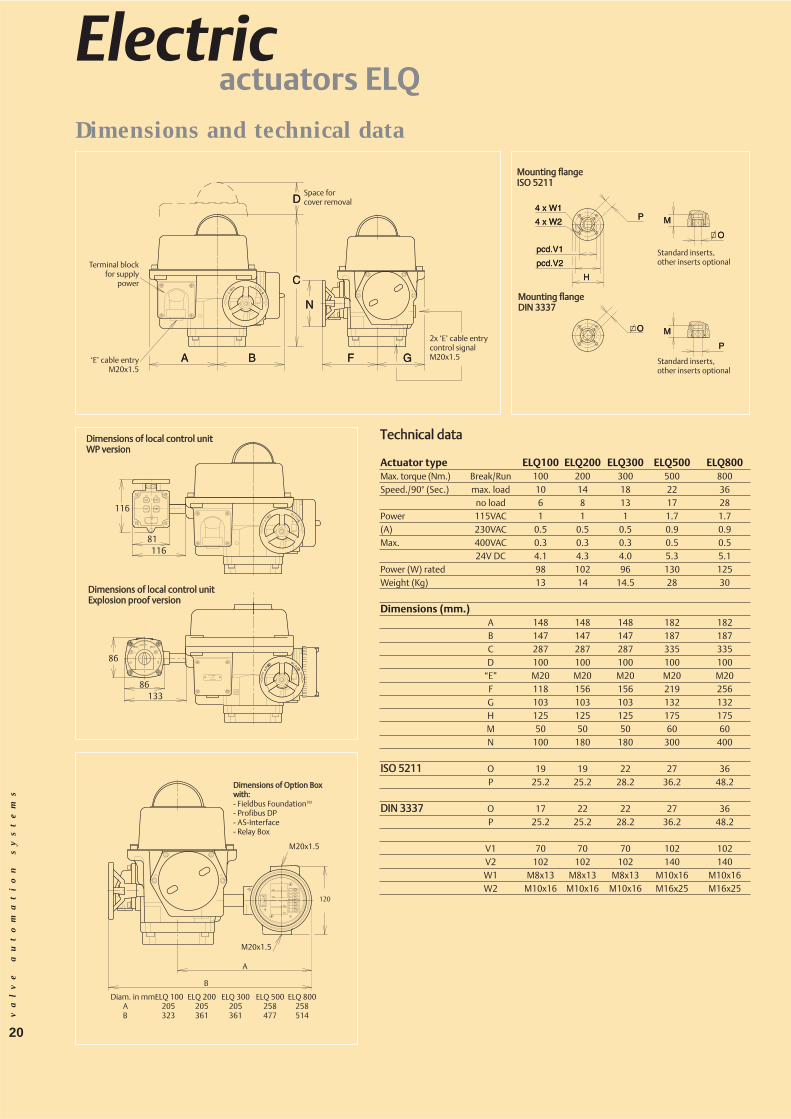
Dimensions and technical data
TTeecchhnniiccaall ddaattaa
Actuator type ELQ100 ELQ200 ELQ300 ELQ500 ELQ800Max. torque (Nm.) Break/Run 100 200 300 500 800Speed./90° (Sec.) max. load 10 14 18 22 36
no load 6 8 13 17 28Power 115VAC 1 1 1 1.7 1.7(A) 230VAC 0.5 0.5 0.5 0.9 0.9Max. 400VAC 0.3 0.3 0.3 0.5 0.5
24V DC 4.1 4.3 4.0 5.3 5.1Power (W) rated 98 102 96 130 125Weight (Kg) 13 14 14.5 28 30
Dimensions (mm.)A 148 148 148 182 182B 147 147 147 187 187C 287 287 287 335 335D 100 100 100 100 100
“E” M20 M20 M20 M20 M20F 118 156 156 219 256G 103 103 103 132 132H 125 125 125 175 175M 50 50 50 60 60N 100 180 180 300 400
IISSOO 55221111 O 19 19 22 27 36P 25.2 25.2 28.2 36.2 48.2
DDIINN 33333377 O 17 22 22 27 36P 25.2 25.2 28.2 36.2 48.2
V1 70 70 70 102 102V2 102 102 102 140 140W1 M8x13 M8x13 M8x13 M10x16 M10x16W2 M10x16 M10x16 M10x16 M16x25 M16x25
Terminal blockfor supply
power
Space forcover removal
2x ‘E’ cable entrycontrol signalM20x1.5‘E’ cable entry
M20x1.5
MMoouunnttiinngg ffllaannggeeIISSOO 55221111
MMoouunnttiinngg ffllaannggeeDDIINN 33333377
Standard inserts, other inserts optional
Standard inserts, other inserts optional
DDiimmeennssiioonnss ooff llooccaall ccoonnttrrooll uunniittWWPP vveerrssiioonn
DDiimmeennssiioonnss ooff llooccaall ccoonnttrrooll uunniittEExxpplloossiioonn pprrooooff vveerrssiioonn
DDiimmeennssiioonnss ooff OOppttiioonn BBooxxwwiitthh::- Fieldbus FoundationTM
- Profibus DP- AS-Interface- Relay Box
Diam. in mmELQ 100 ELQ 200 ELQ 300 ELQ 500 ELQ 800A 205 205 205 258 258B 323 361 361 477 514
M20x1.5
M20x1.5
20
A
B
Mounting flange ISO 5211
Mounting flange DIN 3337
Space for cover removal
Handwheel
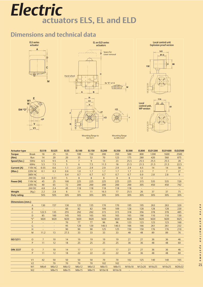
Actuator type ELS18 ELS25 EL55 EL100 EL150 EL200 EL350 EL500 EL800 ELD1200 ELD1600 ELD2500Torque Break 18 25 55 100 150 200 350 500 800 1200 1600 2500(Nm) Run 14 20 20 35 53 70 123 175 280 420 560 875Speed (Sec..)) 50Hz 6.5 9.5 6 7 9 13 23 25.5 25.5 25.5 25.5 28
60Hz 5.5 7.5 5 6 7.5 11.5 18 21.5 21.5 21.5 21.5 22.5Current (A) 110V AC 0.55 0.6 1.1 2.9 2.9 2.9 2.9 2.9 4.5 14 14 58(Max.) 220V AC 0.1 0.3 0.6 1.0 1.7 1.7 1.7 1.7 2.3 7 7 27
380V AC - - 0.4 0.7 0.7 0.7 0.7 0.7 0.9 2.8 2.8 924V DC 0.8 0.51 5 8 8 8 8 8 12 - - -
Power (W) 110V AC 45 25 100 225 225 225 225 225 315 535 535 720220V AC 40 65 72 200 200 200 200 200 305 450 450 79224V DC 4.8 2.4 45 118 118 118 118 118 - - - -
Weight (Kg.) 2.2 2.8 6 11 11 16.5 17 25.5 26 37 37 75Duty rating 50% 50% 30% 30% 30% 30% 30% 30% 30% 30% 30% 30%
Dimensions (mm.)A 130 157 130 135 135 170 170 195 195 263 263 320B - - 60 82 82 109 109 128 128 128 128 220C 122.5 135 255 292 292 315 315 318 356 378 378 485D 85 100 145 165 165 165 165 165 190 110 110 130
“E” M20 M20 M20 M20 M20 M20 M20 M20 M20 M20 M20 M25F - - 70 77 77 96 96 123 123 123 123 160G - - 95 120 120 140.5 140.5 166 166 261 261 232H - - 90 90 90 125 125 150 150 176 176 210M 11.2 13 27.5 33 33 33 33 48 48 89 89 76
ISO 5211 O 7 10 14 19 19 19 19 27 27 36 36 46P 11 12 18 25 25 25 25 36 36 48 48 60
DIN 3337 O 7 10 14 17 17 17 17 27 27 36 36 46P 11 12 18 22 22 22 22 36 36 48 48 60
V1 42 50 50 50 50 70 70 102 125 140 140 165V2 - 70 70 70 70 102 102 - - - - -W1 M6x9 M6x12 M6x12 M6x12 M6x12 M8x15 M8x15 M10x18 M12x20 M16x25 M16x25 M20x32W2 - M8x15 M8x15 M8x15 M8x15 M10x18 M10x18 - - - - -
va
lv
e
au
to
ma
ti
on
s
ys
te
ms
Space for cover removal
EELL eenn EELLDD sseerriieessaaccttuuaattoorrss
EELLSS sseerriieessaaccttuuaattoorr
Hand wheel
Mounting flange to ISO 5211
Mounting flange to DIN 3337
LLooccaall ccoonnttrrooll uunniittEExxpplloossiioonn pprrooooff vveerrssiioonn
LLooccaall ccoonnttrrooll uunniitt,,WWPP vveerrssiioonn
21
Electricactuators ELS, EL and ELD
Dimensions and technical data

EUROPE, MIDDLE EAST & AFRICA- P.O. Box 223
7550 AE Hengelo (O)Asveldweg 117556 BT Hengelo (O)HollandT +31 74 256 10 10F +31 74 291 09 38E Info.ValveAutomation-EMA
@EmersonProcess.com
GERMANY- Postfach 500155
D-47870 WillichSiemensring 112 D-47877 Willich T +49 2154 499660F +49 2154 499 66 13E Info.ValveAutomation-BRD
@EmersonProcess.com
UNITED KINGDOM- 6 Bracken Hill
South West Industrial EstatePeterleeCo Durham SR8 2LST +44 (0) 191 5180020F +44 (0) 191 5180032E Info.ValveAutomation-UK
@EmersonProcess.com
www.El-O-Matic.com
NORTH & SOUTH AMERICA- 9009 King Palm Drive
TampaFlorida33619U.S.A.T +1 813 630 2255F +1 281 630 9449E Info.ValveAutomation-USA
@EmersonProcess.com
SOUTH AFRICA- P.O. Box
Isando16002 Monteer RoadIsandoSouth AfricaT +27 11 974 3336F +27 11 974 7005E Info.ValveAutomation-SA
@EmersonProcess.com
SINGAPORE- Emerson Process Management,
Valve Automation division 9 Gul Road #01-02 Singapore 629361 Tel: +(65) 6501 4600 Fax: +(65) 6268 0028E Info.ValveAutomation-AP
@EmersonProcess.com
DOC.BR.E 06.03
All Rights Reserved.Important: We reserve the right to modify or improve the designs orspecifications of the products mentioned in this manual at any timewithout notice. Emerson Process Management does not assumeresponsibility for the selection, use or maintenance of any product.Responsibility for proper selection, use and maintenance of anyEmerson Process Management product remains solely with the pur-chaser.EL-O-MATIC® is a registered trademark of EL-O-MATIC B.V.PosiFlex™ is a trademark of EL-O-MATIC B.V.PROFIBUS® is a registered trademark of PROFIBUS International. Foundation Fieldbus® is a registered trademark of FieldbusFoundation.©2006 Emerson
Your distributor :