sysmex kx-21 hematology analyzer - instruction manual
TRANSCRIPT
OPERATOR’S MANUALAUTOMATED HEMATOLOGY ANALYZER
KX-21
CHAPTER 1: INTRODUCTIONCHAPTER 2: SAMPLE ANALYSISCHAPTER 3: DISPLAY AND PROCESSING OF ANALYSIS RESULTSCHAPTER 4: MAINTENANCE AND SUPPLIES REPLACEMENTCHAPTER 5: QUALITY CONTROLCHAPTER 6: CALIBRATIONCHAPTER 7: TROUBLESHOOTINGCHAPTER 8: ADJUSTMENTCHAPTER 9: FUNCTIONAL DESCRIPTIONCHAPTER 10: INSTRUMENT SETUPAPPENDIX A: INSTALLATIONAPPENDIX B: TECHNICAL INFORMATIONINDEX
SYSMEX CORPORATIONKOBE, JAPAN
Copyright 1997 - 2000 by SYSMEX CORPORATION
All rights reserved. No part of this Operator’s Manual may be Code No. 461-2261-1reproduced in any form or by any means whatsoever without PRINTED IN JAPANprior written permission of SYSMEX CORPORATION. Date of Last Revision: January 2000
Sysmex KX-21 Operator’s Manual -- Revised October 1998
• Sysmex is a registered trademark of SYSMEX CORPORATION.• CELLCLEAN, CELLPACK, EIGHTCHECK-3WP, STROMATOLYSER-WH are
trademarks of SYSMEX CORPORATION.
• Cubitainer is a registered trademark of Hedwin Corporation.• Teflon is a registered trademark of E.I. du Pont de Nemours & Co., Inc.• VENOJECT is a registered trademark of Terumo Corporation.
• Other trademarks referenced are property of their respective owners.
• It is prohibited to reproduce part or all of the contents of this Manual without permission.• The display screens carried in this Manual may in some cases differ from actual screens.• We reserve the right to make further improvements and incorporate them in our products,
which then will have some points that differ from descriptions in this Manual.• Patient names and doctor names are entered for information and illustration purposes only,
and do not imply real specific persons.
Sysmex KX-21 Operator’s Manual -- Revised October 1998 I
RECEIVING INSTRUCTIONS
The KX-21 has been thoroughly tested before shipment, and has been packagedcarefully to prevent damage from shipping and handling. Reagents and options havealso been sent and will arrive at approximately the same time as the analyzer. Followthese guidelines when the system arrives:
• Check to see that the arrows on the sides of the packages are pointing up. If thearrows do not point up, remark this information on the bill of lading.
• Visually inspect the outside of the package for rips, dents, or possible shippingdamage. Document any sign of damage on the bill of lading, regardless of howinsignificant it may appear. This is for your protection!
• Notify your service representative that the KX-21 system and its componentshave arrived.
• Wait for your service representative to unpack the system and open thepackages.
• Follow the unpacking and storage instructions provided on the outside of thepackage. Special requirements such as refrigeration are clearly marked on theoutside of the carton and will be included in the unpacking instructions andpackage inserts.
WARRANTY INFORMATION
All instruments manufactured by Sysmex® are warranted against defective materialsor workmanship for a period of one year commencing on the installation date at thecustomer's required location.
This Warranty does not cover any defect, malfunction, or damage due to:
1. Accident, neglect or willful mistreatment of the product
2. Failure to use, operate, service, or maintain the product in accordance with theapplicable Sysmex Operator's Manual
3. Failure to use the appropriate reagents or chemicals specified for the product
Sysmex KX-21 Operator’s Manual -- Revised October 1998II
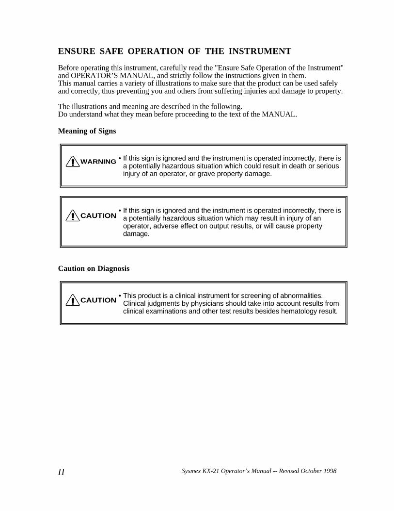
ENSURE SAFE OPERATION OF THE INSTRUMENT
Before operating this instrument, carefully read the "Ensure Safe Operation of the Instrument"and OPERATOR’S MANUAL, and strictly follow the instructions given in them.This manual carries a variety of illustrations to make sure that the product can be used safelyand correctly, thus preventing you and others from suffering injuries and damage to property.
The illustrations and meaning are described in the following.Do understand what they mean before proceeding to the text of the MANUAL.
Meaning of Signs
• If this sign is ignored and the instrument is operated incorrectly, there isa potentially hazardous situation which could result in death or seriousinjury of an operator, or grave property damage.
• If this sign is ignored and the instrument is operated incorrectly, there isa potentially hazardous situation which may result in injury of anoperator, adverse effect on output results, or will cause propertydamage.
Caution on Diagnosis
• This product is a clinical instrument for screening of abnormalities.Clinical judgments by physicians should take into account results fromclinical examinations and other test results besides hematology result.
WARNING
CAUTION
CAUTION
Sysmex KX-21 Operator’s Manual -- Revised October 1998 III
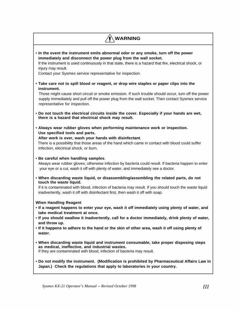
WARNING
• In the event the instrument emits abnormal odor or any smoke, turn off the powerimmediately and disconnect the power plug from the wall socket.If the instrument is used continuously in that state, there is a hazard that fire, electrical shock, orinjury may result.Contact your Sysmex service representative for inspection.
• Take care not to spill blood or reagent, or drop wire staples or paper clips into theinstrument.Those might cause short circuit or smoke emission. If such trouble should occur, turn off the powersupply immediately and pull off the power plug from the wall socket. Then contact Sysmex servicerepresentative for inspection.
• Do not touch the electrical circuits inside the cover. Especially if your hands are wet,there is a hazard that electrical shock may result.
• Always wear rubber gloves when performing maintenance work or inspection.Use specified tools and parts.After work is over, wash your hands with disinfectant.There is a possibility that those areas of the hand which came in contact with blood could sufferinfection, electrical shock, or burn.
• Be careful when handling samples.Always wear rubber gloves; otherwise infection by bacteria could result. If bacteria happen to enteryour eye or a cut, wash it off with plenty of water, and immediately see a doctor.
• When discarding waste liquid, or disassembling/assembling the related parts, do nottouch the waste liquid.If it is contaminated with blood, infection of bacteria may result. If you should touch the waste liquidinadvertently, wash it off with disinfectant first, then wash it off with soap.
When Handling Reagent• If a reagent happens to enter your eye, wash it off immediately using plenty of water, and
take medical treatment at once.• If you should swallow it inadvertently, call for a doctor immediately, drink plenty of water,
and throw up.• If it happens to adhere to the hand or the skin of other area, wash it off using plenty of
water.
• When discarding waste liquid and instrument consumable, take proper disposing stepsas medical, ineffective, and industrial wastes.If they are contaminated with blood, infection of bacteria may result.
• Do not modify the instrument. (Modification is prohibited by Pharmaceutical Affairs Law inJapan.) Check the regulations that apply to laboratories in your country.
Sysmex KX-21 Operator’s Manual -- Revised October 1998I V
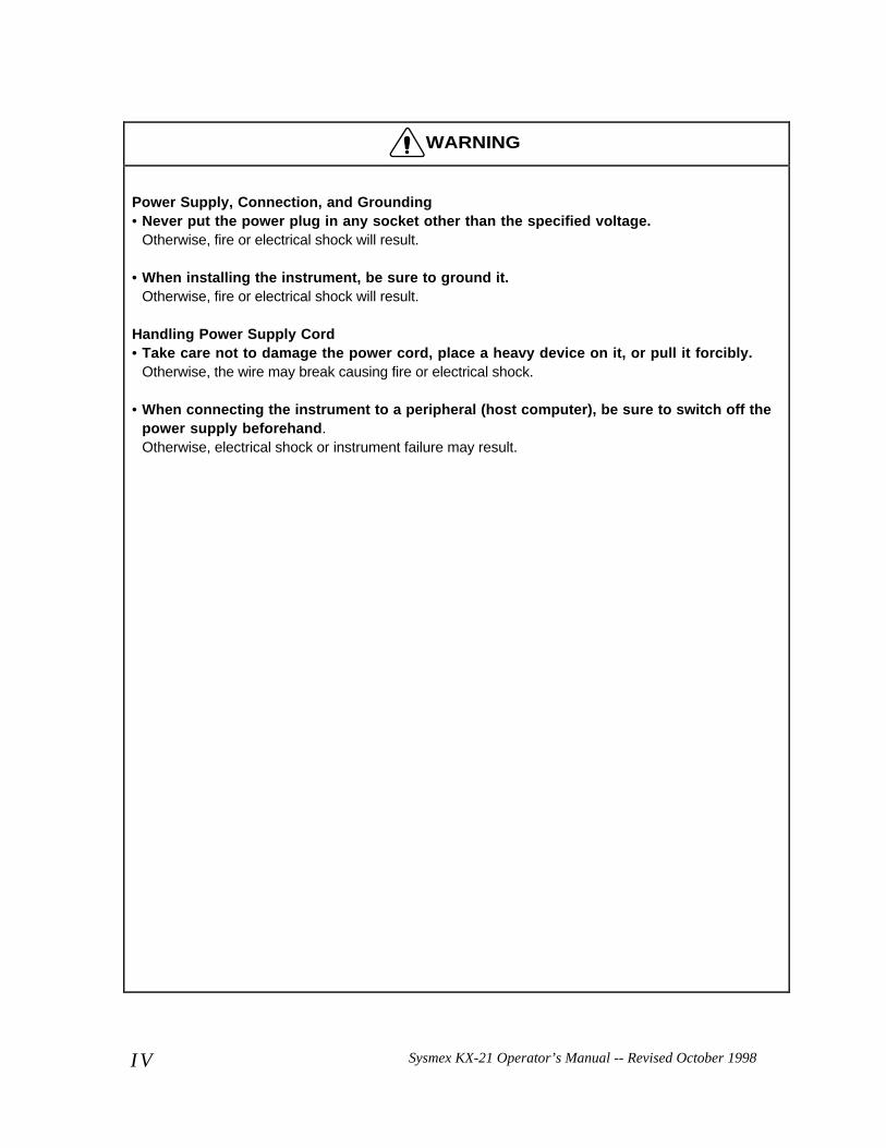
WARNING
Power Supply, Connection, and Grounding• Never put the power plug in any socket other than the specified voltage.
Otherwise, fire or electrical shock will result.
• When installing the instrument, be sure to ground it.Otherwise, fire or electrical shock will result.
Handling Power Supply Cord• Take care not to damage the power cord, place a heavy device on it, or pull it forcibly.
Otherwise, the wire may break causing fire or electrical shock.
• When connecting the instrument to a peripheral (host computer), be sure to switch off thepower supply beforehand.Otherwise, electrical shock or instrument failure may result.
Sysmex KX-21 Operator’s Manual -- Revised October 1998 V
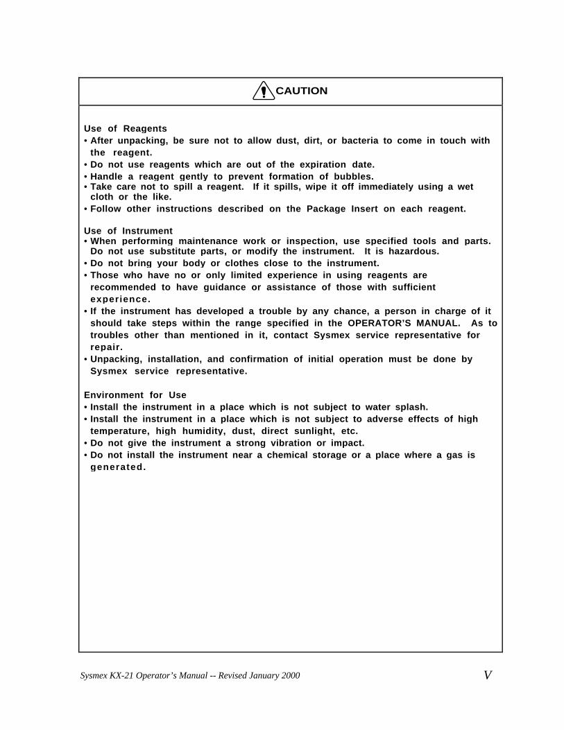
CAUTION
Use of Reagents• After unpacking, be sure not to allow dust, dirt, or bacteria to come in touch with
the reagent.• Do not use reagents which are out of the expiration date.• Handle a reagent gently to prevent formation of bubbles.• Take care not to spill a reagent. If it spills, wipe it off immediately using a wet
cloth or the like.• Follow other instructions described on the Package Insert on each reagent.
Use of Instrument• When performing maintenance work or inspection, use specified tools and parts.
Do not use substitute parts, or modify the instrument. It is hazardous.• Do not bring your body or clothes close to the instrument.• Those who have no or only limited experience in using reagents are
recommended to have guidance or assistance of those with sufficientexperience.
• If the instrument has developed a trouble by any chance, a person in charge of itshould take steps within the range specified in the OPERATOR’S MANUAL. As totroubles other than mentioned in it, contact Sysmex service representative forrepair.
• Unpacking, installation, and confirmation of initial operation must be done bySysmex service representative.
Environment for Use• Install the instrument in a place which is not subject to water splash.• Install the instrument in a place which is not subject to adverse effects of high
temperature, high humidity, dust, direct sunlight, etc.• Do not give the instrument a strong vibration or impact.• Do not install the instrument near a chemical storage or a place where a gas is
generated.
Sysmex KX-21 Operator’s Manual -- Revised January 2000
Sysmex KX-21 Operator’s Manual -- Revised October 1998V I
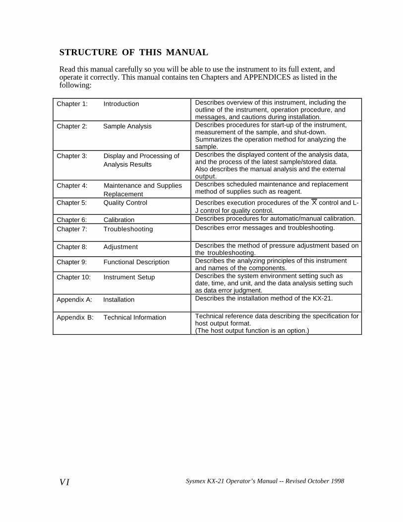
STRUCTURE OF THIS MANUAL
Read this manual carefully so you will be able to use the instrument to its full extent, andoperate it correctly. This manual contains ten Chapters and APPENDICES as listed in thefollowing:
Chapter 1: Introduction Describes overview of this instrument, including theoutline of the instrument, operation procedure, andmessages, and cautions during installation.
Chapter 2: Sample Analysis Describes procedures for start-up of the instrument,measurement of the sample, and shut-down.Summarizes the operation method for analyzing thesample.
Chapter 3: Display and Processing ofAnalysis Results
Describes the displayed content of the analysis data,and the process of the latest sample/stored data.Also describes the manual analysis and the externaloutput.
Chapter 4: Maintenance and SuppliesReplacement
Describes scheduled maintenance and replacementmethod of supplies such as reagent.
Chapter 5: Quality Control Describes execution procedures of the X control and L-J control for quality control.
Chapter 6: Calibration Describes procedures for automatic/manual calibration.
Chapter 7: Troubleshooting Describes error messages and troubleshooting.
Chapter 8: Adjustment Describes the method of pressure adjustment based onthe troubleshooting.
Chapter 9: Functional Description Describes the analyzing principles of this instrumentand names of the components.
Chapter 10: Instrument Setup Describes the system environment setting such asdate, time, and unit, and the data analysis setting suchas data error judgment.
Appendix A: Installation Describes the installation method of the KX-21.
Appendix B: Technical Information Technical reference data describing the specification forhost output format.(The host output function is an option.)
Sysmex KX-21 Operator’s Manual -- Revised October 1998 VII
INTRODUCTION
Thank you for purchasing the Sysmex® Automated Hematology Analyzer KX-21.Carefully read the OPERATOR'S MANUAL for correct use of the unit.Keep this MANUAL handy after reading. It will continue to be of your service in findingspecific information about this instrument.
Sysmex KX-21 Operator’s Manual -- Revised October 1998VIII
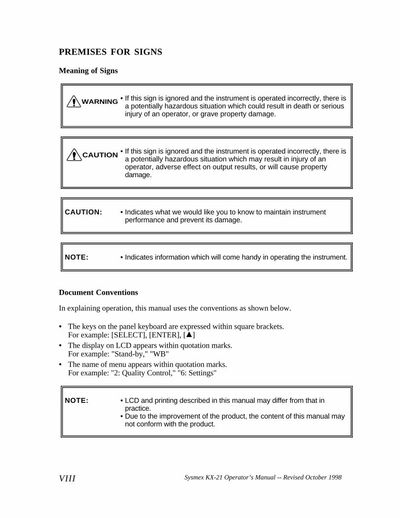
PREMISES FOR SIGNS
Meaning of Signs
• If this sign is ignored and the instrument is operated incorrectly, there isa potentially hazardous situation which could result in death or seriousinjury of an operator, or grave property damage.
• If this sign is ignored and the instrument is operated incorrectly, there isa potentially hazardous situation which may result in injury of anoperator, adverse effect on output results, or will cause propertydamage.
CAUTION: • Indicates what we would like you to know to maintain instrumentperformance and prevent its damage.
NOTE: • Indicates information which will come handy in operating the instrument.
Document Conventions
In explaining operation, this manual uses the conventions as shown below.
• The keys on the panel keyboard are expressed within square brackets.For example: [SELECT], [ENTER], [ ]
• The display on LCD appears within quotation marks.For example: "Stand-by," "WB"
• The name of menu appears within quotation marks.For example: "2: Quality Control," "6: Settings"
NOTE: • LCD and printing described in this manual may differ from that inpractice.
• Due to the improvement of the product, the content of this manual maynot conform with the product.
WARNING
CAUTION
Sysmex KX-21 Operator’s Manual -- Revised January 2000 i
KX-21 OPERATOR’S MANUALTABLE OF CONTENTS
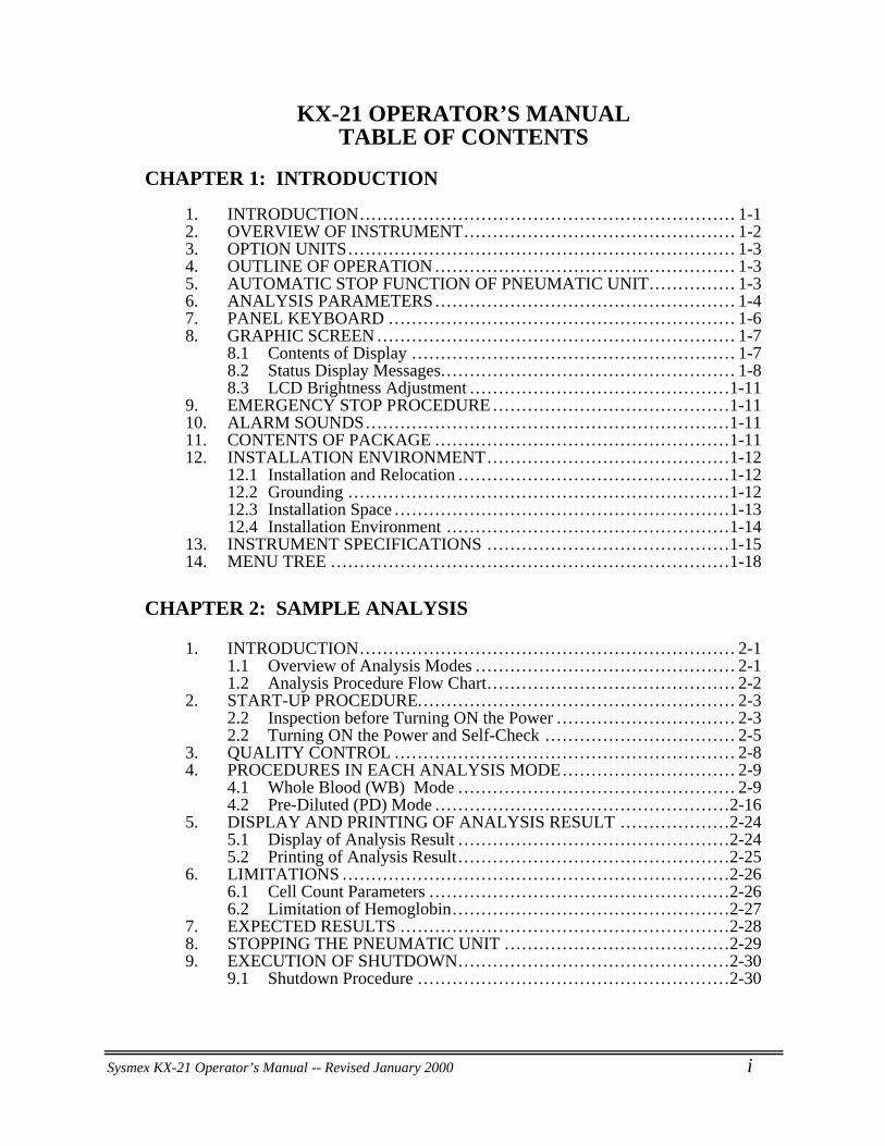
CHAPTER 1: INTRODUCTION
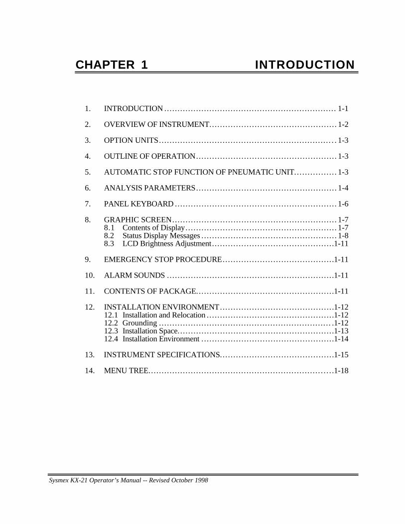
1. INTRODUCTION... . . . . . . . . . . . . . . . . . . . . . . . . . . . . . . . . . . . . . . . . . . . . . . . . . . . . . . . . . . . . . . 1-12. OVERVIEW OF INSTRUMENT... . . . . . . . . . . . . . . . . . . . . . . . . . . . . . . . . . . . . . . . . . . . . 1-23. OPTION UNITS... . . . . . . . . . . . . . . . . . . . . . . . . . . . . . . . . . . . . . . . . . . . . . . . . . . . . . . . . . . . . . . . . 1-34. OUTLINE OF OPERATION ... . . . . . . . . . . . . . . . . . . . . . . . . . . . . . . . . . . . . . . . . . . . . . . . . . 1-35. AUTOMATIC STOP FUNCTION OF PNEUMATIC UNIT... . . . . . . . . . . . . 1-36. ANALYSIS PARAMETERS... . . . . . . . . . . . . . . . . . . . . . . . . . . . . . . . . . . . . . . . . . . . . . . . . . 1-47. PANEL KEYBOARD .... . . . . . . . . . . . . . . . . . . . . . . . . . . . . . . . . . . . . . . . . . . . . . . . . . . . . . . . . 1-68. GRAPHIC SCREEN ... . . . . . . . . . . . . . . . . . . . . . . . . . . . . . . . . . . . . . . . . . . . . . . . . . . . . . . . . . . . 1-7
8.1 Contents of Display .. . . . . . . . . . . . . . . . . . . . . . . . . . . . . . . . . . . . . . . . . . . . . . . . . . . . . . . 1-78.2 Status Display Messages.. . . . . . . . . . . . . . . . . . . . . . . . . . . . . . . . . . . . . . . . . . . . . . . . . . 1-88.3 LCD Brightness Adjustment .. . . . . . . . . . . . . . . . . . . . . . . . . . . . . . . . . . . . . . . . . . . .1-11
9. EMERGENCY STOP PROCEDURE ... . . . . . . . . . . . . . . . . . . . . . . . . . . . . . . . . . . . . . .1-1110. ALARM SOUNDS... . . . . . . . . . . . . . . . . . . . . . . . . . . . . . . . . . . . . . . . . . . . . . . . . . . . . . . . . . . . .1-1111. CONTENTS OF PACKAGE ... . . . . . . . . . . . . . . . . . . . . . . . . . . . . . . . . . . . . . . . . . . . . . . . .1-1112. INSTALLATION ENVIRONMENT... . . . . . . . . . . . . . . . . . . . . . . . . . . . . . . . . . . . . . . .1-12
12.1 Installation and Relocation .. . . . . . . . . . . . . . . . . . . . . . . . . . . . . . . . . . . . . . . . . . . . . .1-1212.2 Grounding ... . . . . . . . . . . . . . . . . . . . . . . . . . . . . . . . . . . . . . . . . . . . . . . . . . . . . . . . . . . . . . . .1-1212.3 Installation Space .. . . . . . . . . . . . . . . . . . . . . . . . . . . . . . . . . . . . . . . . . . . . . . . . . . . . . . . . .1-1312.4 Installation Environment .. . . . . . . . . . . . . . . . . . . . . . . . . . . . . . . . . . . . . . . . . . . . . . . .1-14
13. INSTRUMENT SPECIFICATIONS ... . . . . . . . . . . . . . . . . . . . . . . . . . . . . . . . . . . . . . . .1-1514. MENU TREE ... . . . . . . . . . . . . . . . . . . . . . . . . . . . . . . . . . . . . . . . . . . . . . . . . . . . . . . . . . . . . . . . . . .1-18
CHAPTER 2: SAMPLE ANALYSIS
1. INTRODUCTION... . . . . . . . . . . . . . . . . . . . . . . . . . . . . . . . . . . . . . . . . . . . . . . . . . . . . . . . . . . . . . . 2-11.1 Overview of Analysis Modes .. . . . . . . . . . . . . . . . . . . . . . . . . . . . . . . . . . . . . . . . . . . . 2-11.2 Analysis Procedure Flow Chart. . . . . . . . . . . . . . . . . . . . . . . . . . . . . . . . . . . . . . . . . . . 2-2
2. START-UP PROCEDURE... . . . . . . . . . . . . . . . . . . . . . . . . . . . . . . . . . . . . . . . . . . . . . . . . . . . . 2-32.2 Inspection before Turning ON the Power .. . . . . . . . . . . . . . . . . . . . . . . . . . . . . . 2-32.2 Turning ON the Power and Self-Check ... . . . . . . . . . . . . . . . . . . . . . . . . . . . . . . 2-5
3. QUALITY CONTROL ... . . . . . . . . . . . . . . . . . . . . . . . . . . . . . . . . . . . . . . . . . . . . . . . . . . . . . . . . 2-84. PROCEDURES IN EACH ANALYSIS MODE... . . . . . . . . . . . . . . . . . . . . . . . . . . . 2-9
4.1 Whole Blood (WB) Mode ... . . . . . . . . . . . . . . . . . . . . . . . . . . . . . . . . . . . . . . . . . . . . . 2-94.2 Pre-Diluted (PD) Mode ... . . . . . . . . . . . . . . . . . . . . . . . . . . . . . . . . . . . . . . . . . . . . . . . .2-16
5. DISPLAY AND PRINTING OF ANALYSIS RESULT ... . . . . . . . . . . . . . . . .2-245.1 Display of Analysis Result . . . . . . . . . . . . . . . . . . . . . . . . . . . . . . . . . . . . . . . . . . . . . . .2-245.2 Printing of Analysis Result . . . . . . . . . . . . . . . . . . . . . . . . . . . . . . . . . . . . . . . . . . . . . . .2-25
6. LIMITATIONS ... . . . . . . . . . . . . . . . . . . . . . . . . . . . . . . . . . . . . . . . . . . . . . . . . . . . . . . . . . . . . . . . .2-266.1 Cell Count Parameters .. . . . . . . . . . . . . . . . . . . . . . . . . . . . . . . . . . . . . . . . . . . . . . . . . . .2-266.2 Limitation of Hemoglobin.. . . . . . . . . . . . . . . . . . . . . . . . . . . . . . . . . . . . . . . . . . . . . . .2-27
7. EXPECTED RESULTS ... . . . . . . . . . . . . . . . . . . . . . . . . . . . . . . . . . . . . . . . . . . . . . . . . . . . . . .2-288. STOPPING THE PNEUMATIC UNIT ... . . . . . . . . . . . . . . . . . . . . . . . . . . . . . . . . . . . .2-299. EXECUTION OF SHUTDOWN.... . . . . . . . . . . . . . . . . . . . . . . . . . . . . . . . . . . . . . . . . . . .2-30
9.1 Shutdown Procedure .. . . . . . . . . . . . . . . . . . . . . . . . . . . . . . . . . . . . . . . . . . . . . . . . . . . . .2-30
ii Sysmex KX-21 Operator’s Manual -- Revised January 2000
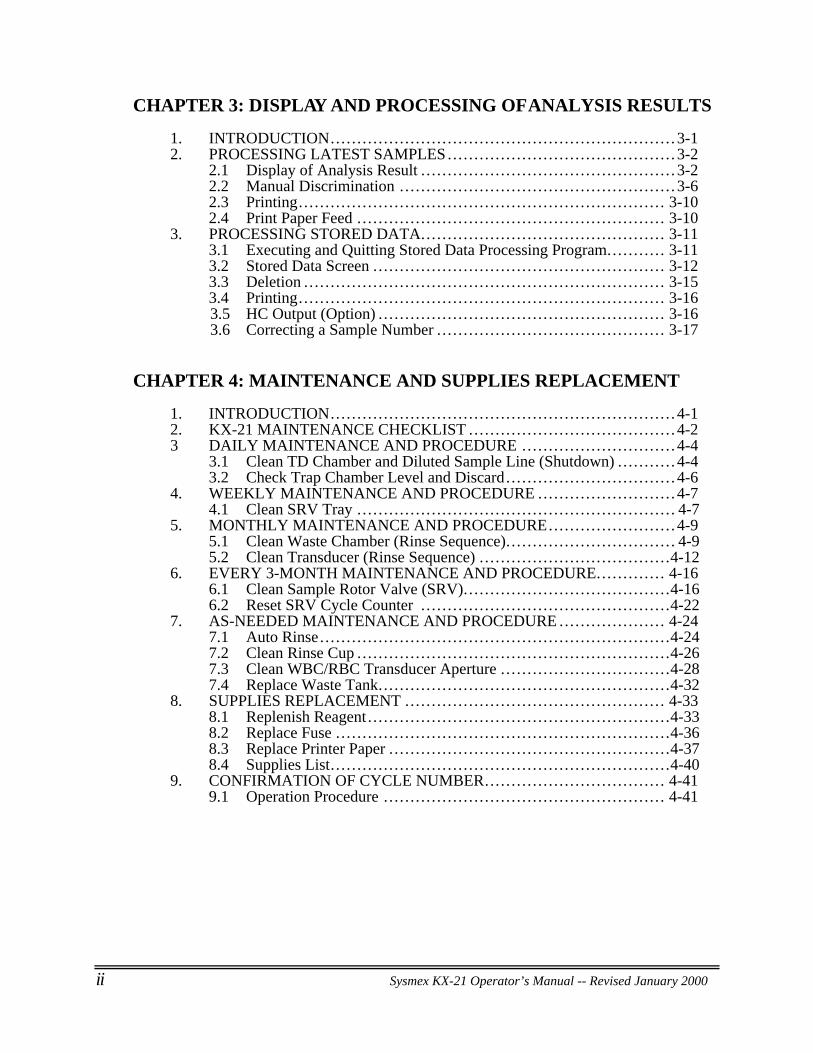
CHAPTER 3: DISPLAY AND PROCESSING OF ANALYSIS RESULTS
1. INTRODUCTION... . . . . . . . . . . . . . . . . . . . . . . . . . . . . . . . . . . . . . . . . . . . . . . . . . . . . . . . . . . . . . . 3-12. PROCESSING LATEST SAMPLES... . . . . . . . . . . . . . . . . . . . . . . . . . . . . . . . . . . . . . . . . 3-2
2.1 Display of Analysis Result . . . . . . . . . . . . . . . . . . . . . . . . . . . . . . . . . . . . . . . . . . . . . . . . 3-22.2 Manual Discrimination .. . . . . . . . . . . . . . . . . . . . . . . . . . . . . . . . . . . . . . . . . . . . . . . . . . . 3-62.3 Printing.. . . . . . . . . . . . . . . . . . . . . . . . . . . . . . . . . . . . . . . . . . . . . . . . . . . . . . . . . . . . . . . . . . . . 3-102.4 Print Paper Feed ... . . . . . . . . . . . . . . . . . . . . . . . . . . . . . . . . . . . . . . . . . . . . . . . . . . . . . . . 3-10
3. PROCESSING STORED DATA... . . . . . . . . . . . . . . . . . . . . . . . . . . . . . . . . . . . . . . . . . . . 3-113.1 Executing and Quitting Stored Data Processing Program... . . . . . . . . 3-113.2 Stored Data Screen .. . . . . . . . . . . . . . . . . . . . . . . . . . . . . . . . . . . . . . . . . . . . . . . . . . . . . . 3-123.3 Deletion .. . . . . . . . . . . . . . . . . . . . . . . . . . . . . . . . . . . . . . . . . . . . . . . . . . . . . . . . . . . . . . . . . . . 3-153.4 Printing.. . . . . . . . . . . . . . . . . . . . . . . . . . . . . . . . . . . . . . . . . . . . . . . . . . . . . . . . . . . . . . . . . . . . 3-163.5 HC Output (Option) .. . . . . . . . . . . . . . . . . . . . . . . . . . . . . . . . . . . . . . . . . . . . . . . . . . . . . 3-163.6 Correcting a Sample Number .. . . . . . . . . . . . . . . . . . . . . . . . . . . . . . . . . . . . . . . . . . 3-17
CHAPTER 4: MAINTENANCE AND SUPPLIES REPLACEMENT
1. INTRODUCTION... . . . . . . . . . . . . . . . . . . . . . . . . . . . . . . . . . . . . . . . . . . . . . . . . . . . . . . . . . . . . . . 4-12. KX-21 MAINTENANCE CHECKLIST ... . . . . . . . . . . . . . . . . . . . . . . . . . . . . . . . . . . . . 4-23 DAILY MAINTENANCE AND PROCEDURE ... . . . . . . . . . . . . . . . . . . . . . . . . . . 4-4
3.1 Clean TD Chamber and Diluted Sample Line (Shutdown) .. . . . . . . . . . 4-43.2 Check Trap Chamber Level and Discard.. . . . . . . . . . . . . . . . . . . . . . . . . . . . . . . 4-6
4. WEEKLY MAINTENANCE AND PROCEDURE ... . . . . . . . . . . . . . . . . . . . . . . . 4-74.1 Clean SRV Tray .. . . . . . . . . . . . . . . . . . . . . . . . . . . . . . . . . . . . . . . . . . . . . . . . . . . . . . . . . . . 4-7
5. MONTHLY MAINTENANCE AND PROCEDURE... . . . . . . . . . . . . . . . . . . . . . 4-95.1 Clean Waste Chamber (Rinse Sequence).. . . . . . . . . . . . . . . . . . . . . . . . . . . . . . . 4-95.2 Clean Transducer (Rinse Sequence) .. . . . . . . . . . . . . . . . . . . . . . . . . . . . . . . . . . .4-12
6. EVERY 3-MONTH MAINTENANCE AND PROCEDURE... . . . . . . . . . . 4-166.1 Clean Sample Rotor Valve (SRV)... . . . . . . . . . . . . . . . . . . . . . . . . . . . . . . . . . . . .4-166.2 Reset SRV Cycle Counter . . . . . . . . . . . . . . . . . . . . . . . . . . . . . . . . . . . . . . . . . . . . . . .4-22
7. AS-NEEDED MAINTENANCE AND PROCEDURE ... . . . . . . . . . . . . . . . . . 4-247.1 Auto Rinse.. . . . . . . . . . . . . . . . . . . . . . . . . . . . . . . . . . . . . . . . . . . . . . . . . . . . . . . . . . . . . . . . .4-247.2 Clean Rinse Cup ... . . . . . . . . . . . . . . . . . . . . . . . . . . . . . . . . . . . . . . . . . . . . . . . . . . . . . . . .4-267.3 Clean WBC/RBC Transducer Aperture .. . . . . . . . . . . . . . . . . . . . . . . . . . . . . . .4-287.4 Replace Waste Tank... . . . . . . . . . . . . . . . . . . . . . . . . . . . . . . . . . . . . . . . . . . . . . . . . . . . .4-32
8. SUPPLIES REPLACEMENT ... . . . . . . . . . . . . . . . . . . . . . . . . . . . . . . . . . . . . . . . . . . . . . . 4-338.1 Replenish Reagent .. . . . . . . . . . . . . . . . . . . . . . . . . . . . . . . . . . . . . . . . . . . . . . . . . . . . . . . .4-338.2 Replace Fuse .. . . . . . . . . . . . . . . . . . . . . . . . . . . . . . . . . . . . . . . . . . . . . . . . . . . . . . . . . . . . . .4-368.3 Replace Printer Paper .. . . . . . . . . . . . . . . . . . . . . . . . . . . . . . . . . . . . . . . . . . . . . . . . . . . .4-378.4 Supplies List. . . . . . . . . . . . . . . . . . . . . . . . . . . . . . . . . . . . . . . . . . . . . . . . . . . . . . . . . . . . . . . .4-40
9. CONFIRMATION OF CYCLE NUMBER... . . . . . . . . . . . . . . . . . . . . . . . . . . . . . . . 4-419.1 Operation Procedure .. . . . . . . . . . . . . . . . . . . . . . . . . . . . . . . . . . . . . . . . . . . . . . . . . . . . 4-41
Sysmex KX-21 Operator’s Manual -- Revised January 2000 iii
CHAPTER 5: QUALITY CONTROL
1. INTRODUCTION... . . . . . . . . . . . . . . . . . . . . . . . . . . . . . . . . . . . . . . . . . . . . . . . . . . . . . . . . . . . . . . 5-11.1 X Control . . . . . . . . . . . . . . . . . . . . . . . . . . . . . . . . . . . . . . . . . . . . . . . . . . . . . . . . . . . . . . . . . . . 5-11.2 Levy-Jennings Control (L-J) .. . . . . . . . . . . . . . . . . . . . . . . . . . . . . . . . . . . . . . . . . . . . . 5-11.3 QC Chart Screen .. . . . . . . . . . . . . . . . . . . . . . . . . . . . . . . . . . . . . . . . . . . . . . . . . . . . . . . . . . . 5-2
2. QC ANALYSIS PROCEDURE ... . . . . . . . . . . . . . . . . . . . . . . . . . . . . . . . . . . . . . . . . . . . . . . 5-42.1 QC Analysis Procedure Flow Chart. . . . . . . . . . . . . . . . . . . . . . . . . . . . . . . . . . . . . . 5-42.2 Execute QC Program... . . . . . . . . . . . . . . . . . . . . . . . . . . . . . . . . . . . . . . . . . . . . . . . . . . . . 5-52.3 Select QC File.. . . . . . . . . . . . . . . . . . . . . . . . . . . . . . . . . . . . . . . . . . . . . . . . . . . . . . . . . . . . . . 5-52.4 Erase All . . . . . . . . . . . . . . . . . . . . . . . . . . . . . . . . . . . . . . . . . . . . . . . . . . . . . . . . . . . . . . . . . . . . . 5-62.5 Set TARGET/LIMIT Values.. . . . . . . . . . . . . . . . . . . . . . . . . . . . . . . . . . . . . . . . . . . . . 5-72.6 Execute X Control. . . . . . . . . . . . . . . . . . . . . . . . . . . . . . . . . . . . . . . . . . . . . . . . . . . . . . . . . . 5-92.7 Execute L-J Control . . . . . . . . . . . . . . . . . . . . . . . . . . . . . . . . . . . . . . . . . . . . . . . . . . . . . . .5-182.8 Exit from QC Control Program... . . . . . . . . . . . . . . . . . . . . . . . . . . . . . . . . . . . . . . .5-24
3. DELETION... . . . . . . . . . . . . . . . . . . . . . . . . . . . . . . . . . . . . . . . . . . . . . . . . . . . . . . . . . . . . . . . . . . . . .5-254. PRINT... . . . . . . . . . . . . . . . . . . . . . . . . . . . . . . . . . . . . . . . . . . . . . . . . . . . . . . . . . . . . . . . . . . . . . . . . . . .5-275. HC OUTPUT (OPTION) .. . . . . . . . . . . . . . . . . . . . . . . . . . . . . . . . . . . . . . . . . . . . . . . . . . . . . 5-29
CHAPTER 6: CALIBRATION
1. INTRODUCTION... . . . . . . . . . . . . . . . . . . . . . . . . . . . . . . . . . . . . . . . . . . . . . . . . . . . . . . . . . . . . . . 6-11.1 Calibration Execution Timing ... . . . . . . . . . . . . . . . . . . . . . . . . . . . . . . . . . . . . . . . . . 6-11.2 Samples Used for Calibration.. . . . . . . . . . . . . . . . . . . . . . . . . . . . . . . . . . . . . . . . . . . . 6-11.3 Reference Values .. . . . . . . . . . . . . . . . . . . . . . . . . . . . . . . . . . . . . . . . . . . . . . . . . . . . . . . . . . 6-11.4 Calibration Flow Chart. . . . . . . . . . . . . . . . . . . . . . . . . . . . . . . . . . . . . . . . . . . . . . . . . . . . . 6-2
2. AUTOMATIC CALIBRATION ... . . . . . . . . . . . . . . . . . . . . . . . . . . . . . . . . . . . . . . . . . . . . . 6-32.1 Executing Automatic Calibration Program ... . . . . . . . . . . . . . . . . . . . . . . . . . . 6-32.2 Automatic Calibration Procedure.. . . . . . . . . . . . . . . . . . . . . . . . . . . . . . . . . . . . . . . . 6-4
3. MANUAL CALIBRATION ... . . . . . . . . . . . . . . . . . . . . . . . . . . . . . . . . . . . . . . . . . . . . . . . . . . 6-93.1 Calculating Calibration Value .. . . . . . . . . . . . . . . . . . . . . . . . . . . . . . . . . . . . . . . . . . . 6-93.2 Manual Calibration Procedure .. . . . . . . . . . . . . . . . . . . . . . . . . . . . . . . . . . . . . . . . . .6-10
iv Sysmex KX-21 Operator’s Manual -- Revised January 2000
CHAPTER 7: TROUBLESHOOTING
1. INTRODUCTION ... . . . . . . . . . . . . . . . . . . . . . . . . . . . . . . . . . . . . . . . . . . . . . . . . . . . . . . . . . . . . . 7-12. WHEN YOU SUSPECT A TROUBLE... . . . . . . . . . . . . . . . . . . . . . . . . . . . . . . . . . . . . . 7-2
2.1 Alphabetical List of Error MessagesDisplayed on Analysis Screen.. . . . . . . . . . . . . . . . . . . . . . . . . . . . . . . . . . . . . . . . . . . 7-3
2.2 Alphabetical List of Error Messages Displayed on HELP Screen .. 7-42.3 Functional List of Error Messages.. . . . . . . . . . . . . . . . . . . . . . . . . . . . . . . . . . . . . . 7-5
3. TROUBLESHOOTING GUIDE ... . . . . . . . . . . . . . . . . . . . . . . . . . . . . . . . . . . . . . . . . . . . . . 7-73.1 Pressure/Vacuum Errors .. . . . . . . . . . . . . . . . . . . . . . . . . . . . . . . . . . . . . . . . . . . . . . . . . 7-73.2 Chamber Errors .. . . . . . . . . . . . . . . . . . . . . . . . . . . . . . . . . . . . . . . . . . . . . . . . . . . . . . . . . 7-103.3 Motor Errors .. . . . . . . . . . . . . . . . . . . . . . . . . . . . . . . . . . . . . . . . . . . . . . . . . . . . . . . . . . . . . 7-133.4 Transducer Errors .. . . . . . . . . . . . . . . . . . . . . . . . . . . . . . . . . . . . . . . . . . . . . . . . . . . . . . . 7-153.5 Temperature Errors .. . . . . . . . . . . . . . . . . . . . . . . . . . . . . . . . . . . . . . . . . . . . . . . . . . . . . 7-163.6 Analysis Errors .. . . . . . . . . . . . . . . . . . . . . . . . . . . . . . . . . . . . . . . . . . . . . . . . . . . . . . . . . . 7-173.7 Memory Errors .. . . . . . . . . . . . . . . . . . . . . . . . . . . . . . . . . . . . . . . . . . . . . . . . . . . . . . . . . . 7-233.8 Others.. . . . . . . . . . . . . . . . . . . . . . . . . . . . . . . . . . . . . . . . . . . . . . . . . . . . . . . . . . . . . . . . . . . . . 7-253.9 Maintenance Errors .. . . . . . . . . . . . . . . . . . . . . . . . . . . . . . . . . . . . . . . . . . . . . . . . . . . . . 7-273.10 Built-in Printer Errors .. . . . . . . . . . . . . . . . . . . . . . . . . . . . . . . . . . . . . . . . . . . . . . . . . . 7-303.11 External Device Errors (When this option is incorporated) .. . . . . . . 7-33
4. STATUS DISPLAY ... . . . . . . . . . . . . . . . . . . . . . . . . . . . . . . . . . . . . . . . . . . . . . . . . . . . . . . . . . 7-34
CHAPTER 8: ADJUSTMENT
1. INTRODUCTION ... . . . . . . . . . . . . . . . . . . . . . . . . . . . . . . . . . . . . . . . . . . . . . . . . . . . . . . . . . . . . . 8-12. ADJUSTMENT OF PRESSURE AND VACUUM .... . . . . . . . . . . . . . . . . . . . . . . 8-2
2.1 Location of Control Knobs .. . . . . . . . . . . . . . . . . . . . . . . . . . . . . . . . . . . . . . . . . . . . . . 8-22.2 Pressure and Vacuum Display .. . . . . . . . . . . . . . . . . . . . . . . . . . . . . . . . . . . . . . . . . . 8-32.3 Adjusting Pressure to 0.5 kg/cm2 .. . . . . . . . . . . . . . . . . . . . . . . . . . . . . . . . . . . . . . . 8-52.4 Adjusting Vacuum to 250 mmHg ... . . . . . . . . . . . . . . . . . . . . . . . . . . . . . . . . . . . . 8-6
Sysmex KX-21 Operator’s Manual -- Revised January 2000 v
CHAPTER 9: FUNCTIONAL DESCRIPTION
1. INTRODUCTION... . . . . . . . . . . . . . . . . . . . . . . . . . . . . . . . . . . . . . . . . . . . . . . . . . . . . . . . . . . . . . . 9-12. DETECTION PRINCIPLE... . . . . . . . . . . . . . . . . . . . . . . . . . . . . . . . . . . . . . . . . . . . . . . . . . . . . 9-2
2.1 DC Detection Method... . . . . . . . . . . . . . . . . . . . . . . . . . . . . . . . . . . . . . . . . . . . . . . . . . . . 9-22.2 Non-Cyanide Hemoglobin Analysis Method ... . . . . . . . . . . . . . . . . . . . . . . . . 9-2
3. MEASURING UNIT HYDRAULIC SYSTEM BLOCK DIAGRAM.... . 9-44. CBC ANALYSIS... . . . . . . . . . . . . . . . . . . . . . . . . . . . . . . . . . . . . . . . . . . . . . . . . . . . . . . . . . . . . . . . 9-5
4.1 WBC/HGB Analysis Flow ... . . . . . . . . . . . . . . . . . . . . . . . . . . . . . . . . . . . . . . . . . . . . . 9-54.2 RBC/PLT Analysis Flow ... . . . . . . . . . . . . . . . . . . . . . . . . . . . . . . . . . . . . . . . . . . . . . . . 9-74.3 Calculation of RBC Constant .. . . . . . . . . . . . . . . . . . . . . . . . . . . . . . . . . . . . . . . . . . . . 9-9
5. BLOOD CELL DISCRIMINATION CIRCUIT ... . . . . . . . . . . . . . . . . . . . . . . . . . 9-105.1 WBC Discriminator .. . . . . . . . . . . . . . . . . . . . . . . . . . . . . . . . . . . . . . . . . . . . . . . . . . . . . 9-105.2 RBC Discriminator .. . . . . . . . . . . . . . . . . . . . . . . . . . . . . . . . . . . . . . . . . . . . . . . . . . . . . . 9-105.3 PLT Discriminator.. . . . . . . . . . . . . . . . . . . . . . . . . . . . . . . . . . . . . . . . . . . . . . . . . . . . . . . 9-10
6. ANALYSIS OF HISTOGRAM .... . . . . . . . . . . . . . . . . . . . . . . . . . . . . . . . . . . . . . . . . . . . 9-116.1 Analysis of WBC Histogram... . . . . . . . . . . . . . . . . . . . . . . . . . . . . . . . . . . . . . . . . . 9-116.2 Analysis of RBC/PLT Histogram ... . . . . . . . . . . . . . . . . . . . . . . . . . . . . . . . . . . . 9-20
7. ELECTRIC SYSTEM .... . . . . . . . . . . . . . . . . . . . . . . . . . . . . . . . . . . . . . . . . . . . . . . . . . . . . . . 9-288. NAMES AND FUNCTIONS OF INSTRUMENTS... . . . . . . . . . . . . . . . . . . . . . 9-30
8.1 Front Panel .. . . . . . . . . . . . . . . . . . . . . . . . . . . . . . . . . . . . . . . . . . . . . . . . . . . . . . . . . . . . . . . 9-308.2 Front Interior .. . . . . . . . . . . . . . . . . . . . . . . . . . . . . . . . . . . . . . . . . . . . . . . . . . . . . . . . . . . . . 9-318.3 Right Side Panel .. . . . . . . . . . . . . . . . . . . . . . . . . . . . . . . . . . . . . . . . . . . . . . . . . . . . . . . . . 9-328.4 Left Side Panel .. . . . . . . . . . . . . . . . . . . . . . . . . . . . . . . . . . . . . . . . . . . . . . . . . . . . . . . . . . . 9-338.5 Left Side Interior.. . . . . . . . . . . . . . . . . . . . . . . . . . . . . . . . . . . . . . . . . . . . . . . . . . . . . . . . . 9-348.6 Rear Panel .. . . . . . . . . . . . . . . . . . . . . . . . . . . . . . . . . . . . . . . . . . . . . . . . . . . . . . . . . . . . . . . . 9-35
CHAPTER 10: INSTRUMENT SETUP
1. INTRODUCTION... . . . . . . . . . . . . . . . . . . . . . . . . . . . . . . . . . . . . . . . . . . . . . . . . . . . . . . . . . . . . 10-12. SYSTEM SETUP... . . . . . . . . . . . . . . . . . . . . . . . . . . . . . . . . . . . . . . . . . . . . . . . . . . . . . . . . . . . . . 10-23. DATE/TIME SETTINGS ... . . . . . . . . . . . . . . . . . . . . . . . . . . . . . . . . . . . . . . . . . . . . . . . . . . . 10-74. PATIENT LIMIT... . . . . . . . . . . . . . . . . . . . . . . . . . . . . . . . . . . . . . . . . . . . . . . . . . . . . . . . . . . . . 10-105. QC SETTINGS ... . . . . . . . . . . . . . . . . . . . . . . . . . . . . . . . . . . . . . . . . . . . . . . . . . . . . . . . . . . . . . . 10-136. HOST SETTINGS (OPTION) ... . . . . . . . . . . . . . . . . . . . . . . . . . . . . . . . . . . . . . . . . . . . . . 10-167. PRINTER SETTINGS ... . . . . . . . . . . . . . . . . . . . . . . . . . . . . . . . . . . . . . . . . . . . . . . . . . . . . . . 10-218. PRINT SET VALUES ... . . . . . . . . . . . . . . . . . . . . . . . . . . . . . . . . . . . . . . . . . . . . . . . . . . . . . . 10-249. PERIPHERAL SETTINGS ... . . . . . . . . . . . . . . . . . . . . . . . . . . . . . . . . . . . . . . . . . . . . . . . . 10-2510. FACTORY SETTINGS ... . . . . . . . . . . . . . . . . . . . . . . . . . . . . . . . . . . . . . . . . . . . . . . . . . . . . 10-27
vi Sysmex KX-21 Operator’s Manual -- Revised January 2000
APPENDIX A: INSTALLATION
1. INTRODUCTION... . . . . . . . . . . . . . . . . . . . . . . . . . . . . . . . . . . . . . . . . . . . . . . . . . . . . . . . . . . . . . A-12. CHECK BEFORE INSTALLATION ... . . . . . . . . . . . . . . . . . . . . . . . . . . . . . . . . . . . . . . A-23. INSTALLATION SPACE... . . . . . . . . . . . . . . . . . . . . . . . . . . . . . . . . . . . . . . . . . . . . . . . . . . . . A-34. REMOVE SHIPPING CLAMPS... . . . . . . . . . . . . . . . . . . . . . . . . . . . . . . . . . . . . . . . . . . . . A-45. CONNECT TUBE... . . . . . . . . . . . . . . . . . . . . . . . . . . . . . . . . . . . . . . . . . . . . . . . . . . . . . . . . . . . . . A-6
5.1 Prepare Reagent.. . . . . . . . . . . . . . . . . . . . . . . . . . . . . . . . . . . . . . . . . . . . . . . . . . . . . . . . . . . A-65.2 Connect CELLPACK ... . . . . . . . . . . . . . . . . . . . . . . . . . . . . . . . . . . . . . . . . . . . . . . . . . . A-65.3 Connect STROMATOLYSER-WH.... . . . . . . . . . . . . . . . . . . . . . . . . . . . . . . . . . A-85.4 Connect Waste Line.. . . . . . . . . . . . . . . . . . . . . . . . . . . . . . . . . . . . . . . . . . . . . . . . . . . . . . A-9
6. SET PRINTER PAPER... . . . . . . . . . . . . . . . . . . . . . . . . . . . . . . . . . . . . . . . . . . . . . . . . . . . . . . A-107. CONNECT POWER CORD ... . . . . . . . . . . . . . . . . . . . . . . . . . . . . . . . . . . . . . . . . . . . . . . . . A-128. TURN POWER ON ... . . . . . . . . . . . . . . . . . . . . . . . . . . . . . . . . . . . . . . . . . . . . . . . . . . . . . . . . . .A-12
APPENDIX B: TECHNICAL INFORMATION
1. OUTPUT FORMAT FOR HOST COMPUTER (Option) .. . . . . . . . . . . . . . . . . .B-11.1 Hardware.. . . . . . . . . . . . . . . . . . . . . . . . . . . . . . . . . . . . . . . . . . . . . . . . . . . . . . . . . . . . . . . . . . . .B-11.2 Software.. . . . . . . . . . . . . . . . . . . . . . . . . . . . . . . . . . . . . . . . . . . . . . . . . . . . . . . . . . . . . . . . . . . . .B-3
INDEX
Sysmex KX-21 Operator’s Manual -- Revised October 1998
CHAPTER 1 INTRODUCTION
1. INTRODUCTION ... . . . . . . . . . . . . . . . . . . . . . . . . . . . . . . . . . . . . . . . . . . . . . . . . . . . . . . . . . . . . . . 1-1
2. OVERVIEW OF INSTRUMENT... . . . . . . . . . . . . . . . . . . . . . . . . . . . . . . . . . . . . . . . . . . . . . 1-2
3. OPTION UNITS... . . . . . . . . . . . . . . . . . . . . . . . . . . . . . . . . . . . . . . . . . . . . . . . . . . . . . . . . . . . . . . . . 1-3
4. OUTLINE OF OPERATION... . . . . . . . . . . . . . . . . . . . . . . . . . . . . . . . . . . . . . . . . . . . . . . . . . . 1-3
5. AUTOMATIC STOP FUNCTION OF PNEUMATIC UNIT.. . . . . . . . . . . . . . . 1-3
6. ANALYSIS PARAMETERS... . . . . . . . . . . . . . . . . . . . . . . . . . . . . . . . . . . . . . . . . . . . . . . . . . . 1-4
7. PANEL KEYBOARD ... . . . . . . . . . . . . . . . . . . . . . . . . . . . . . . . . . . . . . . . . . . . . . . . . . . . . . . . . . . 1-6
8. GRAPHIC SCREEN... . . . . . . . . . . . . . . . . . . . . . . . . . . . . . . . . . . . . . . . . . . . . . . . . . . . . . . . . . . . 1-78.1 Contents of Display.. . . . . . . . . . . . . . . . . . . . . . . . . . . . . . . . . . . . . . . . . . . . . . . . . . . . . . . . 1-78.2 Status Display Messages .. . . . . . . . . . . . . . . . . . . . . . . . . . . . . . . . . . . . . . . . . . . . . . . . . . 1-88.3 LCD Brightness Adjustment.. . . . . . . . . . . . . . . . . . . . . . . . . . . . . . . . . . . . . . . . . . . . .1-11
9. EMERGENCY STOP PROCEDURE... . . . . . . . . . . . . . . . . . . . . . . . . . . . . . . . . . . . . . . .1-11
10. ALARM SOUNDS ... . . . . . . . . . . . . . . . . . . . . . . . . . . . . . . . . . . . . . . . . . . . . . . . . . . . . . . . . . . . .1-11
11. CONTENTS OF PACKAGE... . . . . . . . . . . . . . . . . . . . . . . . . . . . . . . . . . . . . . . . . . . . . . . . . .1-11
12. INSTALLATION ENVIRONMENT... . . . . . . . . . . . . . . . . . . . . . . . . . . . . . . . . . . . . . . . .1-1212.1 Installation and Relocation .. . . . . . . . . . . . . . . . . . . . . . . . . . . . . . . . . . . . . . . . . . . . . . .1-1212.2 Grounding ... . . . . . . . . . . . . . . . . . . . . . . . . . . . . . . . . . . . . . . . . . . . . . . . . . . . . . . . . . . . . . . .1-1212.3 Installation Space.. . . . . . . . . . . . . . . . . . . . . . . . . . . . . . . . . . . . . . . . . . . . . . . . . . . . . . . . . .1-1312.4 Installation Environment .. . . . . . . . . . . . . . . . . . . . . . . . . . . . . . . . . . . . . . . . . . . . . . . . .1-14
13. INSTRUMENT SPECIFICATIONS... . . . . . . . . . . . . . . . . . . . . . . . . . . . . . . . . . . . . . . . .1-15
14. MENU TREE... . . . . . . . . . . . . . . . . . . . . . . . . . . . . . . . . . . . . . . . . . . . . . . . . . . . . . . . . . . . . . . . . . . .1-18
INTRODUCTION
Sysmex KX-21 Operator’s Manual -- Revised October 1998 1-1
1 . INTRODUCTION
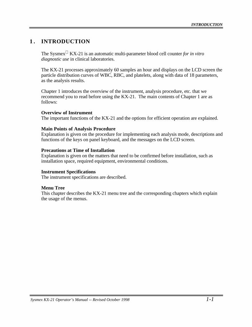
The Sysmex KX-21 is an automatic multi-parameter blood cell counter for in vitrodiagnostic use in clinical laboratories.
The KX-21 processes approximately 60 samples an hour and displays on the LCD screen theparticle distribution curves of WBC, RBC, and platelets, along with data of 18 parameters,as the analysis results.
Chapter 1 introduces the overview of the instrument, analysis procedure, etc. that werecommend you to read before using the KX-21. The main contents of Chapter 1 are asfollows:
Overview of InstrumentThe important functions of the KX-21 and the options for efficient operation are explained.
Main Points of Analysis ProcedureExplanation is given on the procedure for implementing each analysis mode, descriptions andfunctions of the keys on panel keyboard, and the messages on the LCD screen.
Precautions at Time of InstallationExplanation is given on the matters that need to be confirmed before installation, such asinstallation space, required equipment, environmental conditions.
Instrument SpecificationsThe instrument specifications are described.
Menu TreeThis chapter describes the KX-21 menu tree and the corresponding chapters which explainthe usage of the menus.

INTRODUCTION
1-2 Sysmex KX-21 Operator’s Manual -- Revised October 1998
2 . OVERVIEW OF INSTRUMENT
The KX-21 performs speedy and accurate analysis of 18 parameters in blood and detects theabnormal samples. To assure easy sorting of abnormal samples in the laboratory, theinstrument displays abnormal analysis data with abnormal marks attached on the LCDscreen. Thus displayed analysis data allows detecting those samples which are outside thetolerance and need further analysis and reconsideration.
The KX-21 employs three detector blocks and two kinds of reagents for blood analysis. TheWBC count is measured by the WBC detector block using the DC detection method. TheRBC count and platelets are taken by the RBC detector block, also using the DC detectionmethod. The HGB detector block measures the hemoglobin concentration using the non-cyanide hemoglobin method.
Figure 1-2-1: Overview of KX-21
INTRODUCTION
Sysmex KX-21 Operator’s Manual -- Revised October 1998 1-3
3 . OPTION UNITS
This instrument offers several option units to ensure its efficient operation. The options thatcan be used with the KX-21 are:• Serial interface: Outputs analysis data and QC data to the host computer. Ordering
Information: OUTPUT UNIT NO. 1 KX-21 (Part No. 973-4531-1)
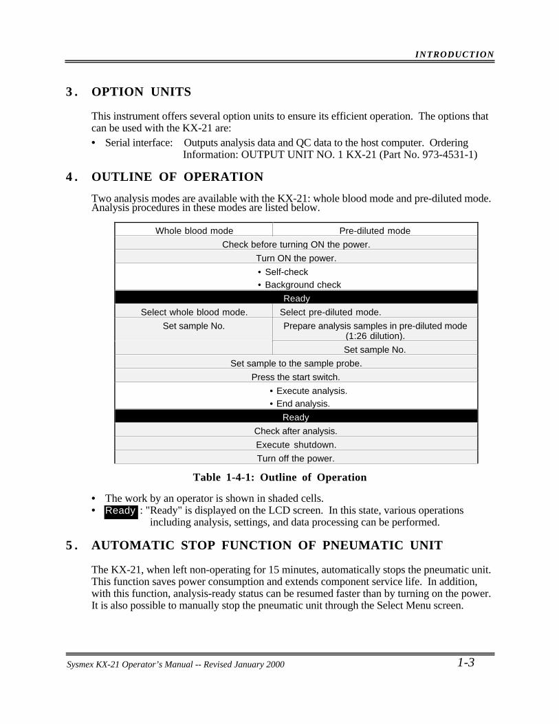
4 . OUTLINE OF OPERATION
Two analysis modes are available with the KX-21: whole blood mode and pre-diluted mode.Analysis procedures in these modes are listed below.
Whole blood mode Pre-diluted mode
Check before turning ON the power.
Turn ON the power.
• Self-check• Background check
Ready
Select whole blood mode. Select pre-diluted mode.
Set sample No. Prepare analysis samples in pre-diluted mode(1:26 dilution).
Set sample No.
Set sample to the sample probe.
Press the start switch.
• Execute analysis.• End analysis.
Ready
Check after analysis.
Execute shutdown.
Turn off the power.
Table 1-4-1: Outline of Operation
• The work by an operator is shown in shaded cells.• : "Ready" is displayed on the LCD screen. In this state, various operations
including analysis, settings, and data processing can be performed.
5 . AUTOMATIC STOP FUNCTION OF PNEUMATIC UNIT
The KX-21, when left non-operating for 15 minutes, automatically stops the pneumatic unit.This function saves power consumption and extends component service life. In addition,with this function, analysis-ready status can be resumed faster than by turning on the power.It is also possible to manually stop the pneumatic unit through the Select Menu screen.
Ready
Sysmex KX-21 Operator’s Manual -- Revised January 2000
INTRODUCTION
1-4 Sysmex KX-21 Operator’s Manual -- Revised October 1998
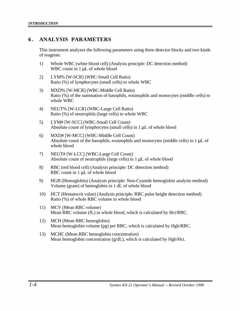
6 . ANALYSIS PARAMETERS
This instrument analyzes the following parameters using three detector blocks and two kindsof reagents:
1) Whole WBC (white blood cell) (Analysis principle: DC detection method)WBC count in 1 µL of whole blood
2) LYM% [W-SCR] (WBC-Small Cell Ratio)Ratio (%) of lymphocytes (small cells) to whole WBC
3) MXD% [W-MCR] (WBC-Middle Cell Ratio)Ratio (%) of the summation of basophils, eosinophils and monocytes (middle cells) towhole WBC
4) NEUT% [W-LCR] (WBC-Large Cell Ratio)Ratio (%) of neutrophils (large cells) to whole WBC
5) LYM# [W-SCC] (WBC-Small Cell Count)Absolute count of lymphocytes (small cells) in 1 µL of whole blood
6) MXD# [W-MCC] (WBC-Middle Cell Count)Absolute count of the basophils, eosinophils and monocytes (middle cells) in 1 µL ofwhole blood
7) NEUT# [W-LCC] (WBC-Large Cell Count)Absolute count of neutrophils (large cells) in 1 µL of whole blood
8) RBC (red blood cell) (Analysis principle: DC detection method)RBC count in 1 µL of whole blood
9) HGB (Hemoglobin) (Analysis principle: Non-Cyanide hemoglobin analysis method)Volume (gram) of hemoglobin in 1 dL of whole blood
10) HCT (Hematocrit value) (Analysis principle: RBC pulse height detection method)Ratio (%) of whole RBC volume in whole blood
11) MCV (Mean RBC volume)Mean RBC volume (fL) in whole blood, which is calculated by Hct/RBC.
12) MCH (Mean RBC hemoglobin)Mean hemoglobin volume (pg) per RBC, which is calculated by Hgb/RBC.
13) MCHC (Mean RBC hemoglobin concentration)Mean hemoglobin concentration (g/dL), which is calculated by Hgb/Hct.
INTRODUCTION
Sysmex KX-21 Operator’s Manual -- Revised October 1998 1-5
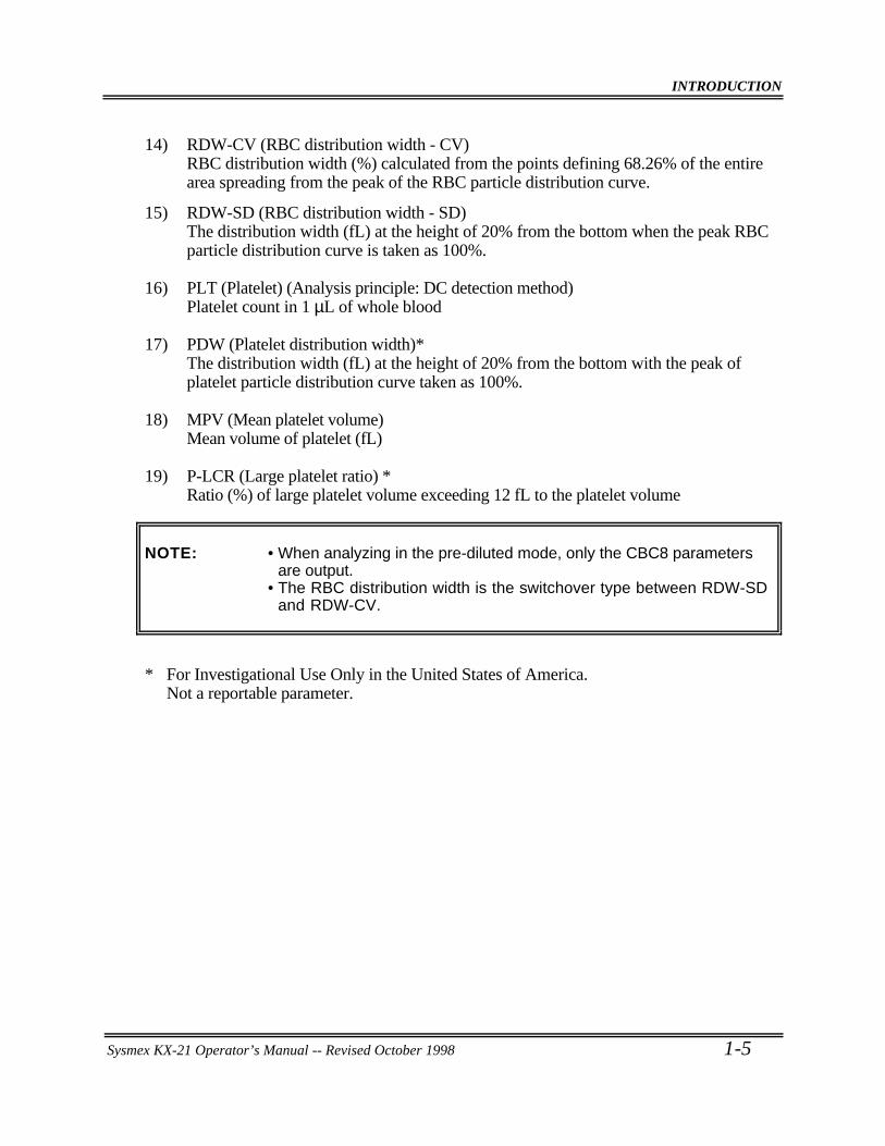
14) RDW-CV (RBC distribution width - CV)RBC distribution width (%) calculated from the points defining 68.26% of the entirearea spreading from the peak of the RBC particle distribution curve.
15) RDW-SD (RBC distribution width - SD)The distribution width (fL) at the height of 20% from the bottom when the peak RBCparticle distribution curve is taken as 100%.
16) PLT (Platelet) (Analysis principle: DC detection method)Platelet count in 1 µL of whole blood
17) PDW (Platelet distribution width)*The distribution width (fL) at the height of 20% from the bottom with the peak ofplatelet particle distribution curve taken as 100%.
18) MPV (Mean platelet volume)Mean volume of platelet (fL)
19) P-LCR (Large platelet ratio) *Ratio (%) of large platelet volume exceeding 12 fL to the platelet volume
NOTE: • When analyzing in the pre-diluted mode, only the CBC8 parametersare output.
• The RBC distribution width is the switchover type between RDW-SDand RDW-CV.
* For Investigational Use Only in the United States of America.Not a reportable parameter.
INTRODUCTION
1-6 Sysmex KX-21 Operator’s Manual -- Revised October 1998
7 . PANEL KEYBOARD
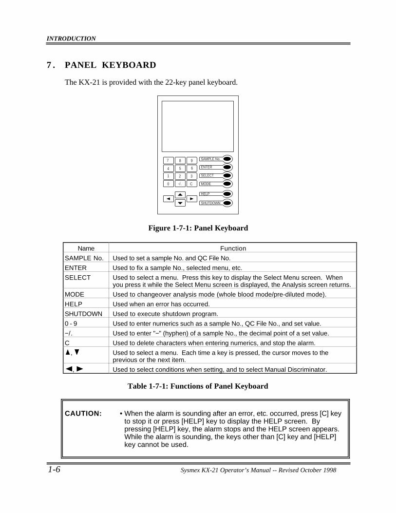
The KX-21 is provided with the 22-key panel keyboard.
7 8 9
4 5 6
1 2 3
0 -/. C
SAMPLE No.
ENTER
SELECT
MODE
HELP
SHUTDOWN
Figure 1-7-1: Panel Keyboard
Name Function
SAMPLE No. Used to set a sample No. and QC File No.
ENTER Used to fix a sample No., selected menu, etc.
SELECT Used to select a menu. Press this key to display the Select Menu screen. Whenyou press it while the Select Menu screen is displayed, the Analysis screen returns.
MODE Used to changeover analysis mode (whole blood mode/pre-diluted mode).
HELP Used when an error has occurred.
SHUTDOWN Used to execute shutdown program.
0 - 9 Used to enter numerics such as a sample No., QC File No., and set value.
−/. Used to enter "−" (hyphen) of a sample No., the decimal point of a set value.
C Used to delete characters when entering numerics, and stop the alarm.
, Used to select a menu. Each time a key is pressed, the cursor moves to theprevious or the next item.
, Used to select conditions when setting, and to select Manual Discriminator.
Table 1-7-1: Functions of Panel Keyboard
CAUTION: • When the alarm is sounding after an error, etc. occurred, press [C] keyto stop it or press [HELP] key to display the HELP screen. Bypressing [HELP] key, the alarm stops and the HELP screen appears.While the alarm is sounding, the keys other than [C] key and [HELP]key cannot be used.
INTRODUCTION
Sysmex KX-21 Operator’s Manual -- Revised October 1998 1-7
8 . GRAPHIC SCREEN
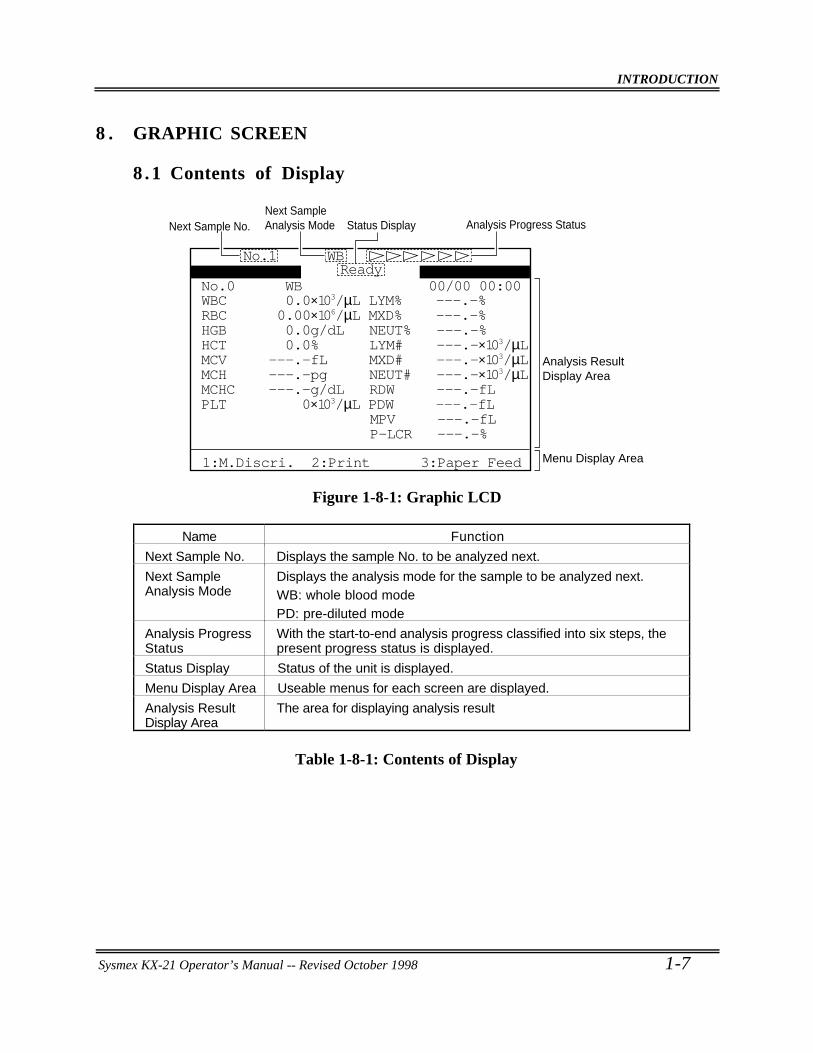
8.1 Contents of Display
00/00 00:00No.0 WB
P-LCR ---.-%MPV ---.-fL
PLT 0×103/µL PDW ---.-fLMCHC ---.-g/dL RDW ---.-fLMCH ---.-pg NEUT# ---.-×103/µLMCV ---.-fL MXD# ---.-×103/µLHCT 0.0% LYM# ---.-×103/µLHGB 0.0g/dL NEUT% ---.-%RBC 0.00×10⁶/µL MXD% ---.-%WBC 0.0×10³/µL LYM% ---.-%
No.1 WB
Next Sample No.Next Sample Analysis Mode Status Display Analysis Progress Status
Analysis ResultDisplay Area
Menu Display Area
Ready
1:M.Discri. 2:Print 3:Paper Feed
Figure 1-8-1: Graphic LCD
Name Function
Next Sample No. Displays the sample No. to be analyzed next.
Next SampleAnalysis Mode
Displays the analysis mode for the sample to be analyzed next.WB: whole blood modePD: pre-diluted mode
Analysis ProgressStatus
With the start-to-end analysis progress classified into six steps, thepresent progress status is displayed.
Status Display Status of the unit is displayed.
Menu Display Area Useable menus for each screen are displayed.
Analysis ResultDisplay Area
The area for displaying analysis result
Table 1-8-1: Contents of Display
INTRODUCTION
1-8 Sysmex KX-21 Operator’s Manual -- Revised October 1998
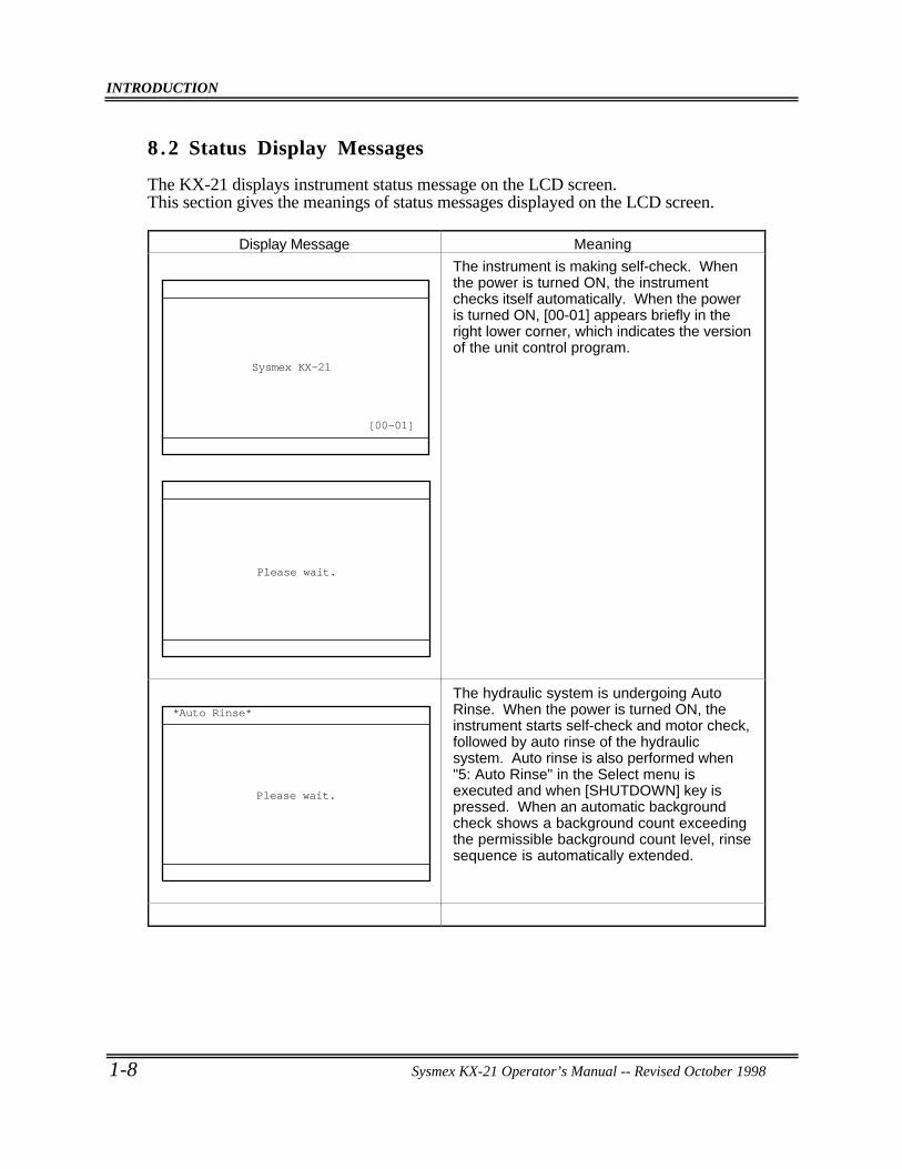
8 .2 Status Display Messages
The KX-21 displays instrument status message on the LCD screen.This section gives the meanings of status messages displayed on the LCD screen.
Display Message Meaning
Sysmex KX-21
[00-01]
Please wait.
The instrument is making self-check. Whenthe power is turned ON, the instrumentchecks itself automatically. When the poweris turned ON, [00-01] appears briefly in theright lower corner, which indicates the versionof the unit control program.
*Auto Rinse*
Please wait.
The hydraulic system is undergoing AutoRinse. When the power is turned ON, theinstrument starts self-check and motor check,followed by auto rinse of the hydraulicsystem. Auto rinse is also performed when"5: Auto Rinse" in the Select menu isexecuted and when [SHUTDOWN] key ispressed. When an automatic backgroundcheck shows a background count exceedingthe permissible background count level, rinsesequence is automatically extended.
INTRODUCTION
Sysmex KX-21 Operator’s Manual -- Revised October 1998 1-9
Display Message Meaning
00/00 00:00No.0 WB
P-LCR ---.-%MPV ---.-fL
PLT 0×103/µL PDW ---.-fLMCHC ---.-g/dL RDW ---.-fLMCH ---.-pg NEUT# ---.-×103/µLMCV ---.-fL MXD# ---.-×103/µLHCT 0.0% LYM# ---.-×103/µLHGB 0.0g/dL NEUT% ---.-%RBC 0.00×10⁶/µL MXD% ---.-%WBC 0.0×10³/µL LYM% ---.-%
No.1 WBReady
1:M.Discri. 2:Print 3:Paper Feed
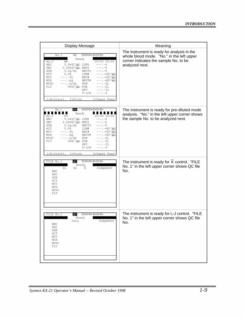
The instrument is ready for analysis in thewhole blood mode. "No." in the left uppercorner indicates the sample No. to beanalyzed next.
00/00 00:00No.0 PD
P-LCR ---.-%MPV ---.-fL
PLT 0×103/µL PDW ---.-fLMCHC ---.-g/dL RDW ---.-fLMCH ---.-pg NEUT# ---.-×103/µLMCV ---.-fL MXD# ---.-×103/µLHCT 0.0% LYM# ---.-×103/µLHGB 0.0g/dL NEUT% ---.-%RBC 0.00×10⁶/µL MXD% ---.-%WBC 0.0×10³/µL LYM% ---.-%
No.1 PDReady
1:M.Discri. 2:Print 3:Paper Feed
The instrument is ready for pre-diluted modeanalysis. "No." in the left upper corner showsthe sample No. to be analyzed next.
FILE No.1 QC
X1 X2 X Judgement WBCRBCHGBHCTMCVMCHMCHCPLT
ReadyThe instrument is ready for X control. "FILENo. 1" in the left upper corner shows QC fileNo.
FILE No.1 QC
Data JudgementWBCRBCHGBHCTMCVMCHMCHCPLT
ReadyThe instrument is ready for L-J control. "FILENo. 1" in the left upper corner shows QC fileNo.
INTRODUCTION
1-10 Sysmex KX-21 Operator’s Manual -- Revised October 1998
Display Message Meaning
*Change Mode*
Please wait.
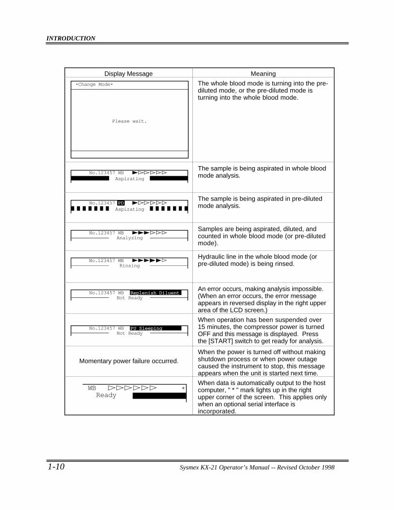
The whole blood mode is turning into the pre-diluted mode, or the pre-diluted mode isturning into the whole blood mode.
No.123457 WBAspirating
The sample is being aspirated in whole bloodmode analysis.
No.123457 PDAspirating
The sample is being aspirated in pre-dilutedmode analysis.
No.123457 WBAnalyzing
Samples are being aspirated, diluted, andcounted in whole blood mode (or pre-dilutedmode).
No.123457 WBRinsing
Hydraulic line in the whole blood mode (orpre-diluted mode) is being rinsed.
No.123457 WBNot Ready
Replenish DiluentAn error occurs, making analysis impossible.(When an error occurs, the error messageappears in reversed display in the right upperarea of the LCD screen.)
No.123457 WBNot Ready
PU Sleeping
When operation has been suspended over15 minutes, the compressor power is turnedOFF and this message is displayed. Pressthe [START] switch to get ready for analysis.
Momentary power failure occurred.When the power is turned off without makingshutdown process or when power outagecaused the instrument to stop, this messageappears when the unit is started next time.
WBReady
*When data is automatically output to the hostcomputer, " * " mark lights up in the rightupper corner of the screen. This applies onlywhen an optional serial interface isincorporated.
INTRODUCTION
Sysmex KX-21 Operator’s Manual -- Revised October 1998 1-11
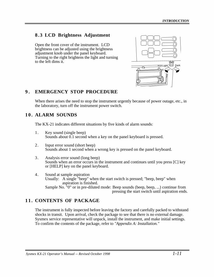
8 .3 LCD Brightness Adjustment
Open the front cover of the instrument. LCDbrightness can be adjusted using the brightnessadjustment knob under the panel keyboard.Turning to the right brightens the light and turningto the left dims it.
9 . EMERGENCY STOP PROCEDURE
When there arises the need to stop the instrument urgently because of power outage, etc., inthe laboratory, turn off the instrument power switch.
10 . ALARM SOUNDS
The KX-21 indicates different situations by five kinds of alarm sounds:
1. Key sound (single beep)Sounds about 0.1 second when a key on the panel keyboard is pressed.
2. Input error sound (short beep)Sounds about 1 second when a wrong key is pressed on the panel keyboard.
3. Analysis error sound (long beep)Sounds when an error occurs in the instrument and continues until you press [C] keyor [HELP] key on the panel keyboard.
4. Sound at sample aspirationUsually: A single "beep" when the start switch is pressed; "beep, beep" when
aspiration is finished.Sample No. "0" or in pre-diluted mode: Beep sounds (beep, beep, ...) continue from
pressing the start switch until aspiration ends.
11 . CONTENTS OF PACKAGE
The instrument is fully inspected before leaving the factory and carefully packed to withstandshocks in transit. Upon arrival, check the package to see that there is no external damage.Sysmex service representative will unpack, install the instrument, and make initial settings.To confirm the contents of the package, refer to "Appendix A: Installation."
DarkLight
INTRODUCTION
1-12 Sysmex KX-21 Operator’s Manual -- Revised October 1998
12 . INSTALLATION ENVIRONMENT
12.1 Installation and Relocation
The KX-21 is installed by Sysmex Service representative. In case relocation becomesnecessary after installation, contact your Sysmex service representative.Pay careful attention to this because if relocation, etc. of the instrument should be conductedby the customer, resulting in any trouble, warranty would not be applied even in thewarranty period.
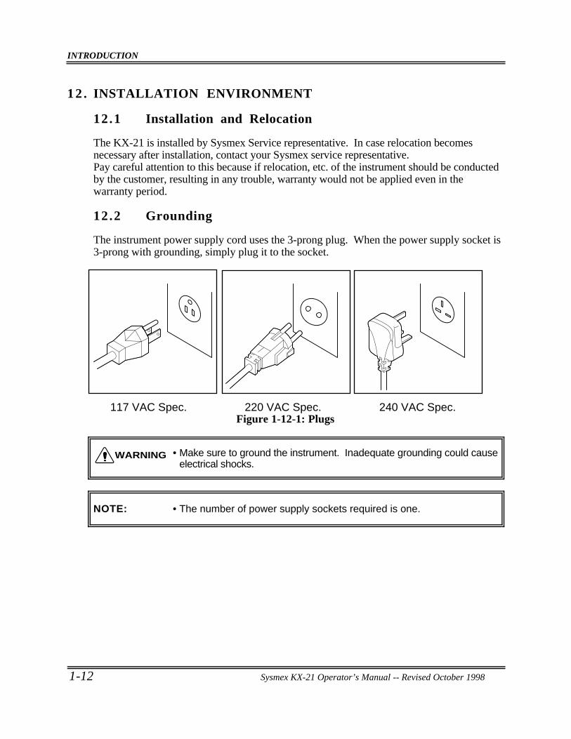
12.2 Grounding
The instrument power supply cord uses the 3-prong plug. When the power supply socket is3-prong with grounding, simply plug it to the socket.
117 VAC Spec. 220 VAC Spec. 240 VAC Spec.Figure 1-12-1: Plugs
• Make sure to ground the instrument. Inadequate grounding could causeelectrical shocks.
NOTE: • The number of power supply sockets required is one.
WARNING
INTRODUCTION
Sysmex KX-21 Operator’s Manual -- Revised October 1998 1-13
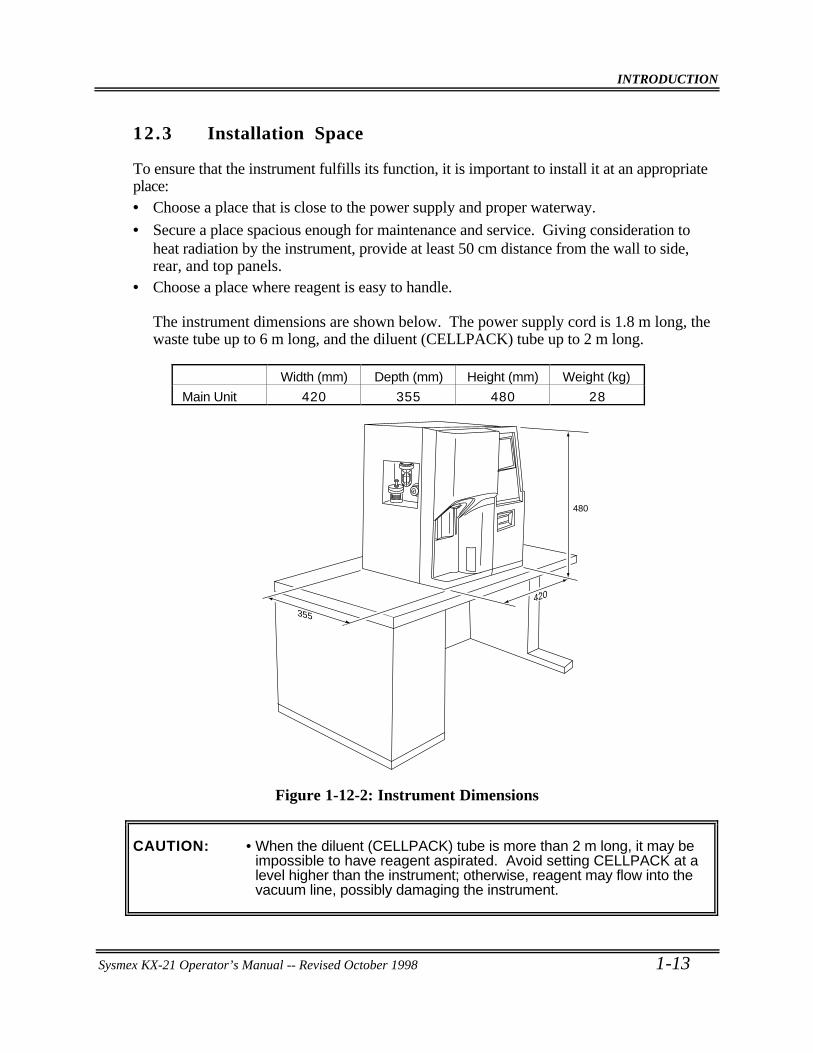
12.3 Installation Space
To ensure that the instrument fulfills its function, it is important to install it at an appropriateplace:• Choose a place that is close to the power supply and proper waterway.
• Secure a place spacious enough for maintenance and service. Giving consideration toheat radiation by the instrument, provide at least 50 cm distance from the wall to side,rear, and top panels.
• Choose a place where reagent is easy to handle.
The instrument dimensions are shown below. The power supply cord is 1.8 m long, thewaste tube up to 6 m long, and the diluent (CELLPACK) tube up to 2 m long.
Width (mm) Depth (mm) Height (mm) Weight (kg)
Main Unit 420 355 480 28
480
355
420
Figure 1-12-2: Instrument Dimensions
CAUTION: • When the diluent (CELLPACK) tube is more than 2 m long, it may beimpossible to have reagent aspirated. Avoid setting CELLPACK at alevel higher than the instrument; otherwise, reagent may flow into thevacuum line, possibly damaging the instrument.
INTRODUCTION
1-14 Sysmex KX-21 Operator’s Manual -- Revised October 1998
12.4 Installation Environment
• Use the instrument at an ambient temperature of 15°C - 30°C (optimum: 23°C).• Use it at a relative humidity range of 30% - 85%.• When air conditioning is used, the maximum cooling capacity of about 172 kcal/hour is
required to offset the heat from the instrument.• Avoid a place that can become extremely hot or cold.• Avoid a place that can be exposed to direct sunlight.• Choose a well-ventilated place.• Avoid a place close to a wireless telegraph or communication facility where high
frequency waves can be generated or radio interference can occur.
INTRODUCTION
Sysmex KX-21 Operator’s Manual -- Revised October 1998 1-15
13 . INSTRUMENT SPECIFICATIONS
Analysis parameters:WBC (White Bloodcell Count), RBC (Red Bloodcell Count), HGB (hemoglobin), HCT(hematocrit), MCV (mean corpuscular volume), MCH (mean corpuscular hemoglobin),MCHC (mean corpuscular hemoglobin concentration), PLT (platelet), RDW-SD (RBCdistribution width-standard deviation), RDW-CV (RBC distribution width-coefficient ofvariation), PDW (platelet distribution width)*, MPV (mean platelet volume), P-LCR (plateletlarge cell ratio)*, LYM% (W-SCR), MXD% (W-MCR), NEUT% (W-LCR), LYM# (W-SCC), MXD# (W-MCC), NEUT# (W-LCC) (RDW-SD or RDW-CV: Switch over type)However, the parameters in pre-diluted mode are eight: WBC, RBC, HGB, HCT, MCV,MCH, MCHC, PLT.
* For Investigational Use Only in the United States of America.Not a reportable parameter.
Display rangeWBC 0.0 - 299.9 (×103/µL)RBC 0.00 - 19.99 (×106/µL)HGB 0 - 25.0 (g/dL)PLT 0 - 1999 (×103/µL)
ReagentDiluent: CELLPACKWBC/HGB lyse reagent: STROMATOLYSER-WH
DetergentCELLCLEAN
Consumption of reagent (per sample)Diluent (CELLPACK): Approx. 30 mLWBC/HGB lyse reagent (STROMATOLYSER-WH): Approx. 1.0 mL
ThroughputApprox. 60 samples/hour
Analysis principleWBC: DC detection methodRBC: DC detection methodHGB: Non-cyanide hemoglobin analysis method
INTRODUCTION
1-16 Sysmex KX-21 Operator’s Manual -- Revised October 1998
ReproducibilityReproducibility is within the following range at the reliability level of 95%.1) Whole blood mode
WBC (4.0 × 10³/µL or over) 3.5% or lessRBC (4.00 × 10⁶/µL or over) 2.0% or lessHGB 1.5% or lessHCT 2.0% or lessMCV 2.0% or lessMCH 2.0% or lessMCHC 2.0% or lessPLT (100 × 103/µL or over) 6.0% or lessLYM# (W-SCC) 15.0% or lessMXD# (W-MCC) (1.0 × 10³/µL or over) 30.0% or lessNEUT# (W-LCC) 15.0% or lessLYM% (W-SCR) 15.0% or lessMXD% (W-MCR) (12% or over) 30.0% or lessNEUT% (W-LCR) 15.0% or lessRDW-SD or RDW-CV 4.0% or lessPDW 12.0% or lessMPV 5.0% or lessP-LCR 20.0% or less
2) Pre-diluted modeWBC (4.0 × 10³/µL or over) 6.0% or lessRBC (4.00 × 10⁶/µL or over) 3.0% or lessHGB 2.5% or lessHCT 3.0% or lessMCV 3.0% or lessMCH 3.0% or lessMCHC 3.0% or lessPLT (100 × 103/µL or over) 9.0% or less
Accuracy1) Whole blood mode
WBC: ±3% or ±0.2 × 10³/µL or lessRBC: ±2% or ±0.03 × 10⁶/µL or lessPLT: ±5% or ±10 × 103/µL or less
2) Pre-diluted modeWBC: ±5% or ±0.3 × 10³/µL or lessRBC: ±3% or ±0.05 × 10⁶/µL or lessPLT: ±8% or ±15 × 103/µL or less
INTRODUCTION
Sysmex KX-21 Operator’s Manual -- Revised October 1998 1-17
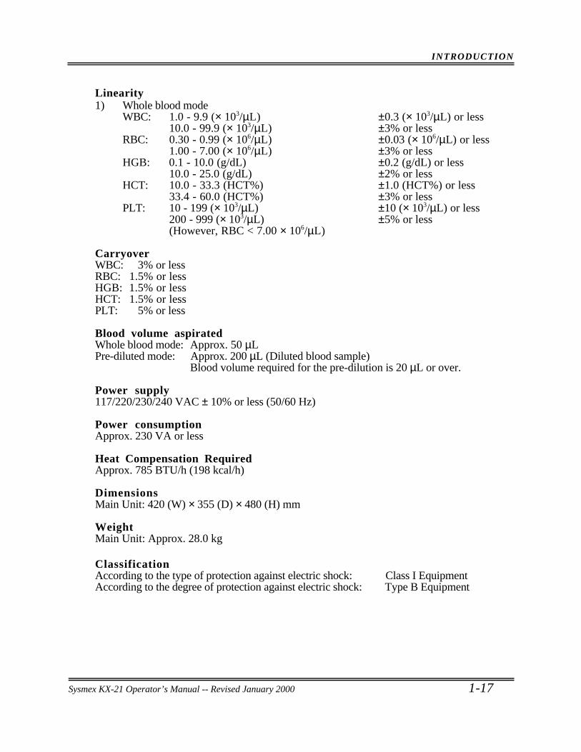
Linearity1) Whole blood mode
WBC: 1.0 - 9.9 (× 103/µL) ±0.3 (× 103/µL) or less10.0 - 99.9 (× 103/µL) ±3% or less
RBC: 0.30 - 0.99 (× 106/µL) ±0.03 (× 106/µL) or less1.00 - 7.00 (× 106/µL) ±3% or less
HGB: 0.1 - 10.0 (g/dL) ±0.2 (g/dL) or less10.0 - 25.0 (g/dL) ±2% or less
HCT: 10.0 - 33.3 (HCT%) ±1.0 (HCT%) or less33.4 - 60.0 (HCT%) ±3% or less
PLT: 10 - 199 (× 103/µL) ±10 (× 103/µL) or less200 - 999 (× 103/µL) ±5% or less(However, RBC < 7.00 × 10⁶/µL)
CarryoverWBC: 3% or lessRBC: 1.5% or lessHGB: 1.5% or lessHCT: 1.5% or lessPLT: 5% or less
Blood volume aspiratedWhole blood mode: Approx. 50 µLPre-diluted mode: Approx. 200 µL (Diluted blood sample)
Blood volume required for the pre-dilution is 20 µL or over.
Power supply117/220/230/240 VAC ± 10% or less (50/60 Hz)
Power consumptionApprox. 230 VA or less
Heat Compensation RequiredApprox. 785 BTU/h (198 kcal/h)
DimensionsMain Unit: 420 (W) × 355 (D) × 480 (H) mm
WeightMain Unit: Approx. 28.0 kg
ClassificationAccording to the type of protection against electric shock: Class I EquipmentAccording to the degree of protection against electric shock: Type B Equipment
Sysmex KX-21 Operator’s Manual -- Revised January 2000
INTRODUCTION
1-18 Sysmex KX-21 Operator’s Manual -- Revised October 1998
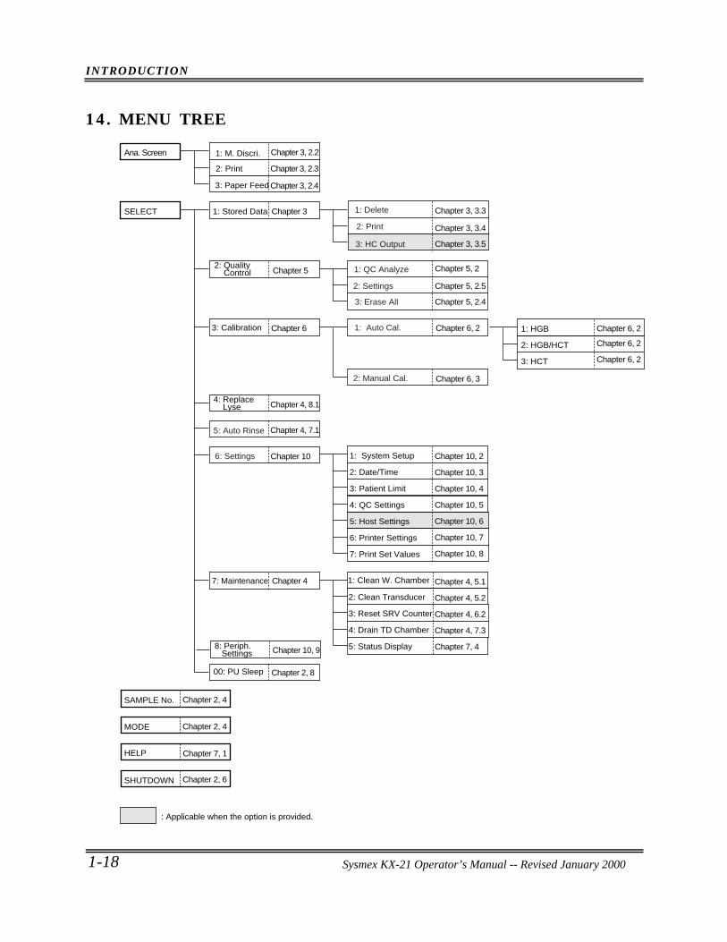
14 . MENU TREE
SELECT
SAMPLE No.
MODE
HELP
SHUTDOWN
1: Stored Data
Chapter 4
Ana. Screen
4: Replace Lyse
3: Calibration
00: PU Sleep
7: Maintenance
2: Clean Transducer
3: Reset SRV Counter
4: Drain TD Chamber
5: Status Display
1: HGB
2: HGB/HCT
3: HCT
1: M. Discri.
2: Print
3: Paper Feed
Chapter 3, 2.2
Chapter 3, 3.3
Chapter 3, 3.4
Chapter 3, 3.5
Chapter 5, 2
Chapter 5, 2.5
Chapter 5, 2.4
Chapter 6, 2
Chapter 6, 3
Chapter 3, 2.3
Chapter 3, 2.4
Chapter 4, 8.1
Chapter 4, 7.1
Chapter 3
Chapter 5
Chapter 6
Chapter 10 Chapter 10, 2
Chapter 10, 3
Chapter 10, 4
Chapter 10, 5
Chapter 10, 6
Chapter 10, 7
Chapter 10, 8
Chapter 4, 5.1
Chapter 4, 5.2
Chapter 4, 6.2
Chapter 4, 7.3
Chapter 7, 4
Chapter 6, 2
Chapter 6, 2
Chapter 6, 2
1: System Setup
2: Date/Time
3: Patient Limit
4: QC Settings
5: Host Settings
6: Printer Settings
7: Print Set Values
Chapter 2, 8
Chapter 2, 4
Chapter 2, 4
Chapter 2, 6
Chapter 7, 1
: Applicable when the option is provided.
2: Print
1: Delete
3: HC Output
1: QC Analyze
3: Erase All
2: Settings
6: Settings
1: Auto Cal.
2: Manual Cal.
5: Auto Rinse
1: Clean W. Chamber
2: Quality Control
8: Periph. Settings Chapter 10, 9
Sysmex KX-21 Operator’s Manual -- Revised January 2000
Sysmex KX-21 Operator’s Manual -- Revised January 2000
CHAPTER 2 SAMPLE ANALYSIS
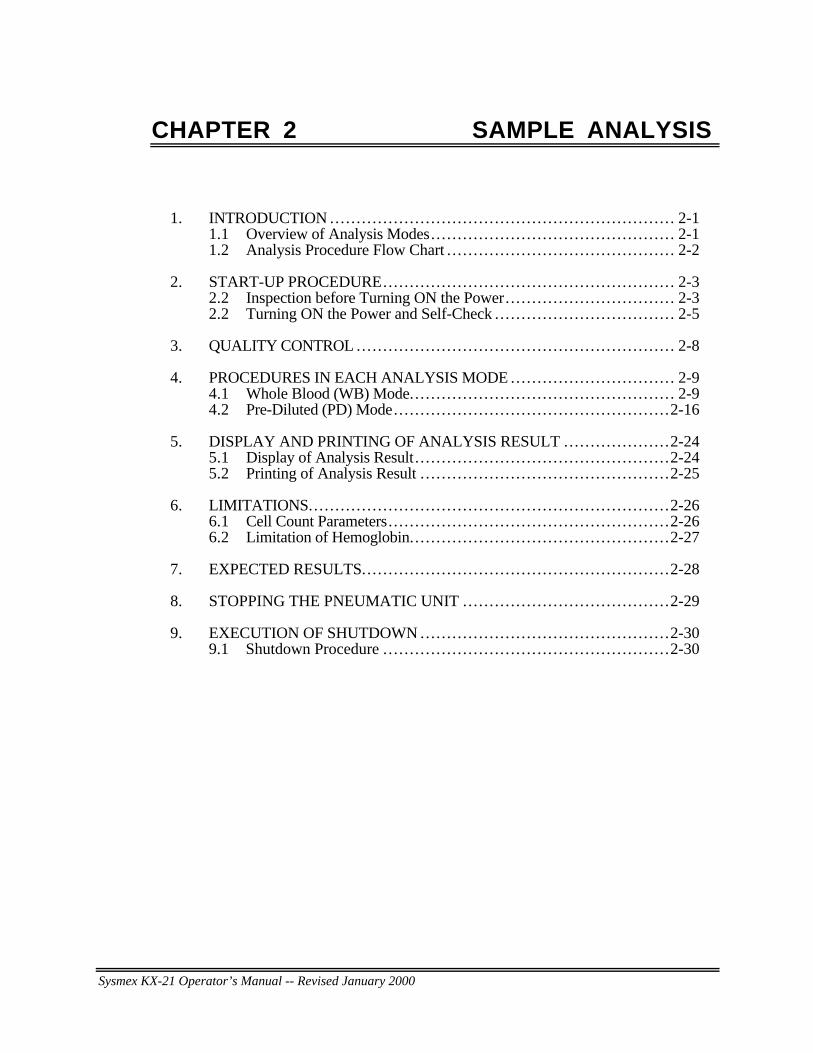
1. INTRODUCTION ... . . . . . . . . . . . . . . . . . . . . . . . . . . . . . . . . . . . . . . . . . . . . . . . . . . . . . . . . . . . . . . 2-11.1 Overview of Analysis Modes.. . . . . . . . . . . . . . . . . . . . . . . . . . . . . . . . . . . . . . . . . . . . . 2-11.2 Analysis Procedure Flow Chart . . . . . . . . . . . . . . . . . . . . . . . . . . . . . . . . . . . . . . . . . . . 2-2
2. START-UP PROCEDURE... . . . . . . . . . . . . . . . . . . . . . . . . . . . . . . . . . . . . . . . . . . . . . . . . . . . . 2-32.2 Inspection before Turning ON the Power.. . . . . . . . . . . . . . . . . . . . . . . . . . . . . . . 2-32.2 Turning ON the Power and Self-Check ... . . . . . . . . . . . . . . . . . . . . . . . . . . . . . . . 2-5
3. QUALITY CONTROL ... . . . . . . . . . . . . . . . . . . . . . . . . . . . . . . . . . . . . . . . . . . . . . . . . . . . . . . . . . 2-8
4. PROCEDURES IN EACH ANALYSIS MODE ... . . . . . . . . . . . . . . . . . . . . . . . . . . . . 2-94.1 Whole Blood (WB) Mode... . . . . . . . . . . . . . . . . . . . . . . . . . . . . . . . . . . . . . . . . . . . . . . . 2-94.2 Pre-Diluted (PD) Mode... . . . . . . . . . . . . . . . . . . . . . . . . . . . . . . . . . . . . . . . . . . . . . . . . .2-16
5. DISPLAY AND PRINTING OF ANALYSIS RESULT ... . . . . . . . . . . . . . . . . .2-245.1 Display of Analysis Result. . . . . . . . . . . . . . . . . . . . . . . . . . . . . . . . . . . . . . . . . . . . . . . .2-245.2 Printing of Analysis Result . . . . . . . . . . . . . . . . . . . . . . . . . . . . . . . . . . . . . . . . . . . . . . .2-25
6. LIMITATIONS... . . . . . . . . . . . . . . . . . . . . . . . . . . . . . . . . . . . . . . . . . . . . . . . . . . . . . . . . . . . . . . . . .2-266.1 Cell Count Parameters.. . . . . . . . . . . . . . . . . . . . . . . . . . . . . . . . . . . . . . . . . . . . . . . . . . . .2-266.2 Limitation of Hemoglobin.. . . . . . . . . . . . . . . . . . . . . . . . . . . . . . . . . . . . . . . . . . . . . . . .2-27
7. EXPECTED RESULTS... . . . . . . . . . . . . . . . . . . . . . . . . . . . . . . . . . . . . . . . . . . . . . . . . . . . . . . .2-28
8. STOPPING THE PNEUMATIC UNIT ... . . . . . . . . . . . . . . . . . . . . . . . . . . . . . . . . . . . .2-29
9. EXECUTION OF SHUTDOWN .... . . . . . . . . . . . . . . . . . . . . . . . . . . . . . . . . . . . . . . . . . . .2-309.1 Shutdown Procedure .. . . . . . . . . . . . . . . . . . . . . . . . . . . . . . . . . . . . . . . . . . . . . . . . . . . . .2-30
SAMPLE ANALYSIS
Sysmex KX-21 Operator’s Manual -- Revised October 2-1
1 . INTRODUCTION
This instrument works in two analysis modes: whole blood mode and pre-diluted mode.This chapter describes the general operation procedures from instrument start-up toshutdown, with the procedures in respective analysis modes.
1 .1 Overview of Analysis Modes
• Whole blood modeThis is the mode of analyzing collected blood sample in the whole blood status. The tubecap is opened and the sample is aspirated through the sample probe one after another.
• Pre-diluted modeThis mode is used in analyzing a minute amount of child's blood, for instance, collectedfrom the earlobe or fingertip. In this mode, blood sample diluted into 1:26 beforeanalysis is used. The sample aspiration procedure is the same as in the whole bloodmode.
NOTE: • In the pre-diluted mode, particle distribution curve and particledistribution analysis data are not output, and the output is confined toonly the CBC8 parameter.
Sysmex KX-21 Operator’s Manual -- Revised December 1999
SAMPLE ANALYSIS
2-2 Sysmex KX-21 Operator’s Manual -- Revised October 1998
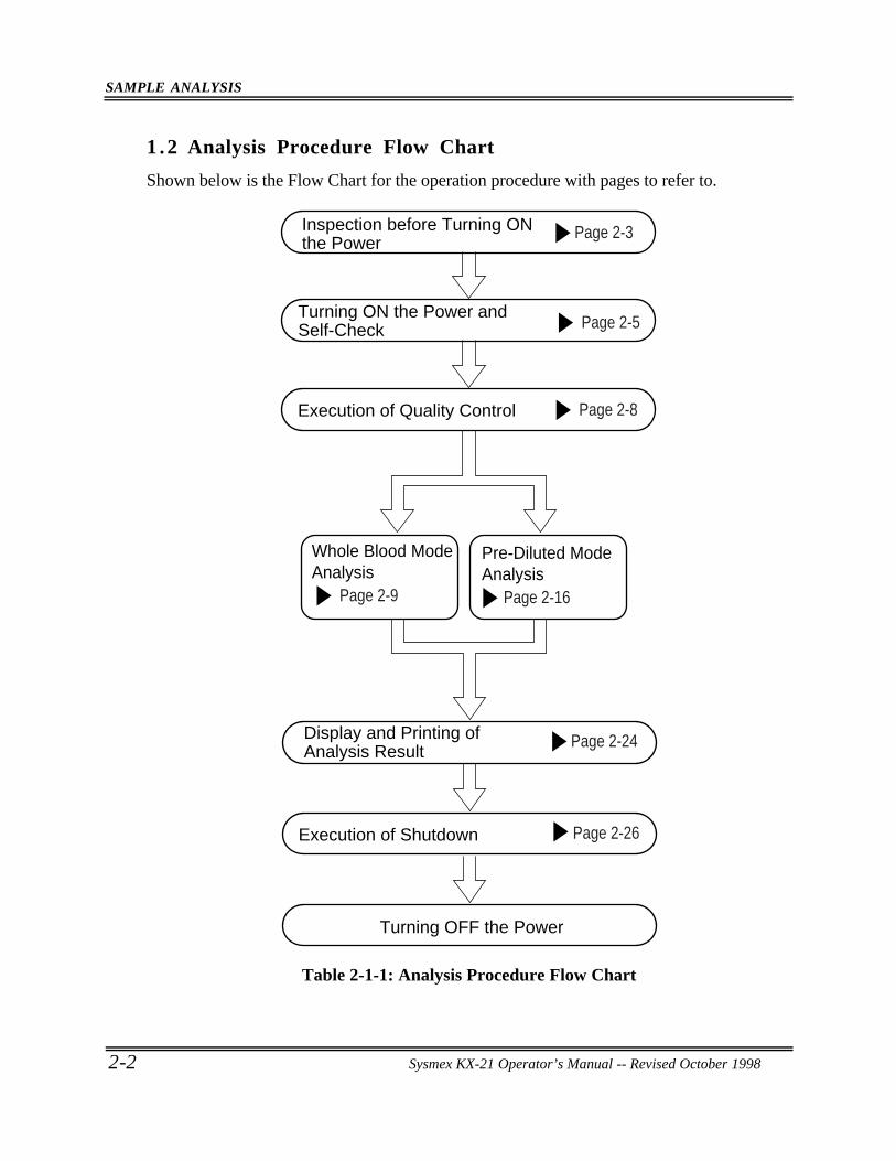
1 .2 Analysis Procedure Flow Chart
Shown below is the Flow Chart for the operation procedure with pages to refer to.
Inspection before Turning ONthe Power
Turning ON the Power and Self-Check
Execution of Quality Control
Display and Printing of Analysis Result
Execution of Shutdown
Turning OFF the Power
Page 2-3
Page 2-5
Page 2-8
Whole Blood Mode Analysis
Pre-Diluted Mode Analysis
Page 2-16Page 2-9
Page 2-24
Page 2-26
Table 2-1-1: Analysis Procedure Flow Chart
SAMPLE ANALYSIS
Sysmex KX-21 Operator’s Manual -- Revised October 1998 2-3
2 . START-UP PROCEDURE
2.1 Inspection before Turning ON the Power
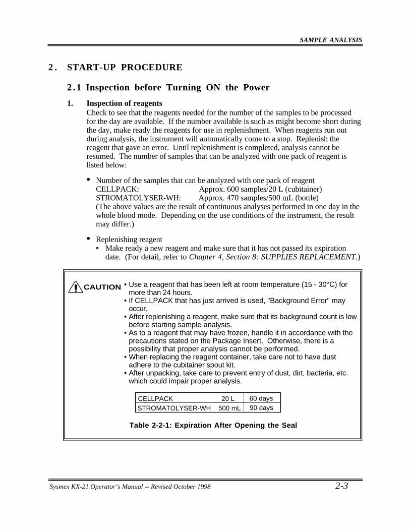
1. Inspection of reagentsCheck to see that the reagents needed for the number of the samples to be processedfor the day are available. If the number available is such as might become short duringthe day, make ready the reagents for use in replenishment. When reagents run outduring analysis, the instrument will automatically come to a stop. Replenish thereagent that gave an error. Until replenishment is completed, analysis cannot beresumed. The number of samples that can be analyzed with one pack of reagent islisted below:
• Number of the samples that can be analyzed with one pack of reagentCELLPACK: Approx. 600 samples/20 L (cubitainer)STROMATOLYSER-WH: Approx. 470 samples/500 mL (bottle)(The above values are the result of continuous analyses performed in one day in thewhole blood mode. Depending on the use conditions of the instrument, the resultmay differ.)
• Replenishing reagent• Make ready a new reagent and make sure that it has not passed its expiration
date. (For detail, refer to Chapter 4, Section 8: SUPPLIES REPLACEMENT.)
• Use a reagent that has been left at room temperature (15 - 30°C) formore than 24 hours.
• If CELLPACK that has just arrived is used, "Background Error" mayoccur.
• After replenishing a reagent, make sure that its background count is lowbefore starting sample analysis.
• As to a reagent that may have frozen, handle it in accordance with theprecautions stated on the Package Insert. Otherwise, there is apossibility that proper analysis cannot be performed.
• When replacing the reagent container, take care not to have dustadhere to the cubitainer spout kit.
• After unpacking, take care to prevent entry of dust, dirt, bacteria, etc.which could impair proper analysis.
CELLPACK 20 LSTROMATOLYSER-WH 500 mL
60 days90 days
Table 2-2-1: Expiration After Opening the Seal
CAUTION
SAMPLE ANALYSIS
2-4 Sysmex KX-21 Operator’s Manual -- Revised October 1998
• We recommend preparing "Reagent Replenishment Record" in which to enter dateof replenishment, name of reagent, reagent lot No., expiration date, name of personwho replenished. Such record would come handy.
2 . Inspection of the instrumentInspect the connection of tubings and cords to see that there are no broken tubes andthe power cord is properly plugged in the outlet.
3 . Inspection of wasteIf waste is found to have collected in the trap chamber on the left side of the unit andthe waste tank (when provided), discard the waste.
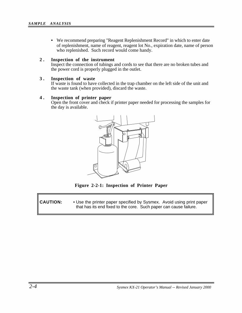
4 . Inspection of printer paperOpen the front cover and check if printer paper needed for processing the samples forthe day is available.
Figure 2-2-1: Inspection of Printer Paper
CAUTION: • Use the printer paper specified by Sysmex. Avoid using print paperthat has its end fixed to the core. Such paper can cause failure.
Sysmex KX-21 Operator’s Manual -- Revised January 2000
SAMPLE ANALYSIS
Sysmex KX-21 Operator’s Manual -- Revised October 1998 2-5
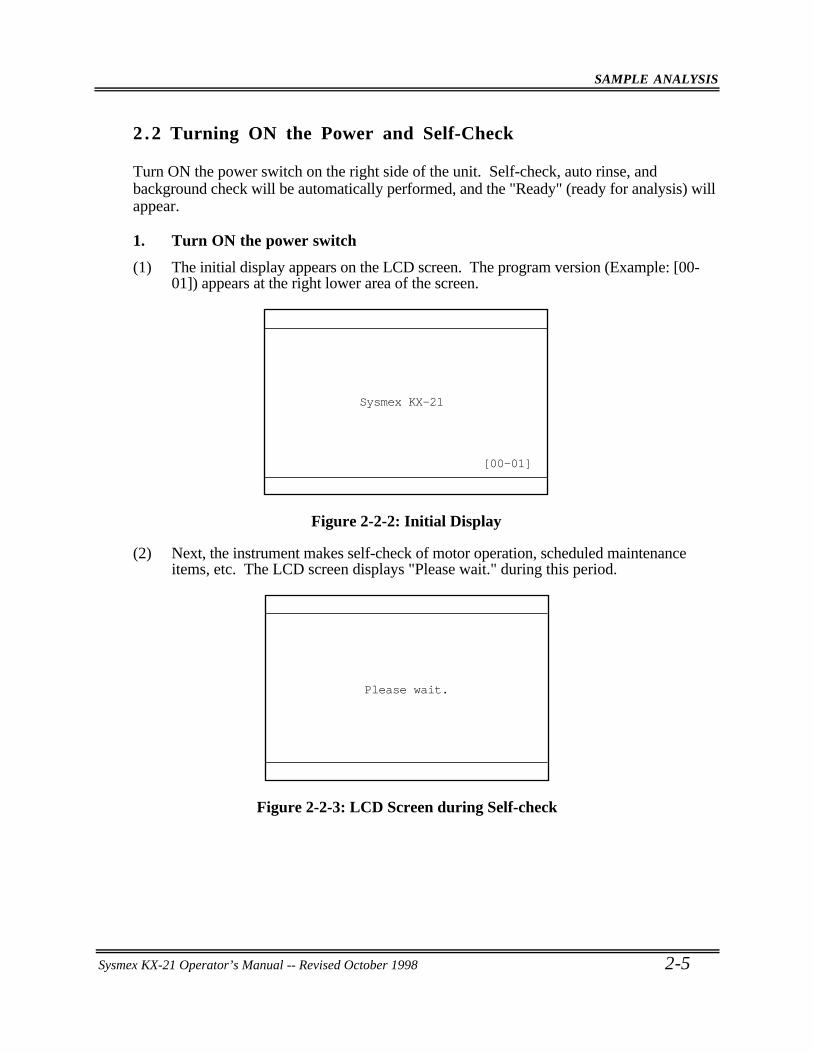
2 .2 Turning ON the Power and Self-Check
Turn ON the power switch on the right side of the unit. Self-check, auto rinse, andbackground check will be automatically performed, and the "Ready" (ready for analysis) willappear.
1. Turn ON the power switch
(1) The initial display appears on the LCD screen. The program version (Example: [00-01]) appears at the right lower area of the screen.
Sysmex KX-21
[00-01]
Figure 2-2-2: Initial Display
(2) Next, the instrument makes self-check of motor operation, scheduled maintenanceitems, etc. The LCD screen displays "Please wait." during this period.
Please wait.
Figure 2-2-3: LCD Screen during Self-check
SAMPLE ANALYSIS
2-6 Sysmex KX-21 Operator’s Manual -- Revised October 1998
CAUTION: • When self-check reveals any error, an error message will appear on theLCD screen. In this case, turn OFF the power once, then turn it ONagain. If the error still occurs, contact Sysmex service representative.
• To ensure optimum operation of the instrument, service counters areprovided for the components which require scheduled maintenance. Ifupon the power turn-on, the counter is found exceeding thepredetermined times, the screen advising scheduled maintenance isdisplayed. When the Scheduled Maintenance screen appears, press[C] key to stop the alarm sound, then perform maintenance operationby following the instructions on the screen.For detail, refer to Chapter 4: INSTRUMENT MAINTENANCE ANDSUPPLIES REPLACEMENT.
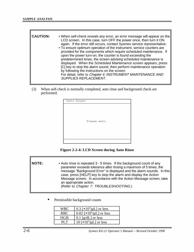
(3) When self-check is normally completed, auto rinse and background check areperformed.
*Auto Rinse*
Please wait.
Figure 2-2-4: LCD Screen during Auto Rinse
NOTE: • Auto rinse is repeated 3 - 5 times. If the background count of anyparameter exceeds tolerance after rinsing a maximum of 5 times, themessage "Background Error" is displayed and the alarm sounds. In thiscase, press [HELP] key to stop the alarm and display the ActionMessage screen. In accordance with the Action Message screen, takean appropriate action.(Refer to Chapter 7: TROUBLESHOOTING.)
• Permissible background counts
WBC 0.3 [×103/µL] or lessRBC 0.02 [×106/µL] or lessHGB 0.1 [g/dL] or lessPLT 10 [×103/µL] or less
SAMPLE ANALYSIS
Sysmex KX-21 Operator’s Manual -- Revised October 1998 2-7
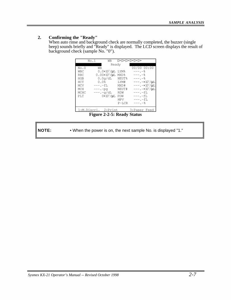
2. Confirming the "Ready"When auto rinse and background check are normally completed, the buzzer (singlebeep) sounds briefly and "Ready" is displayed. The LCD screen displays the result ofbackground check (sample No. "0").
00/00 00:00No.0 WB
P-LCR ---.-%MPV ---.-fL
PLT 0×103/µL PDW ---.-fLMCHC ---.-g/dL RDW ---.-fLMCH ---.-pg NEUT# ---.-×103/µLMCV ---.-fL MXD# ---.-×103/µLHCT 0.0% LYM# ---.-×103/µLHGB 0.0g/dL NEUT% ---.-%RBC 0.00×10⁶/µL MXD% ---.-%WBC 0.0×10³/µL LYM% ---.-%
No.1 WB
1:M.Discri. 2:Print 3:Paper Feed
Ready
Figure 2-2-5: Ready Status
NOTE: • When the power is on, the next sample No. is displayed "1."
SAMPLE ANALYSIS
2-8 Sysmex KX-21 Operator’s Manual -- Revised October 1998
3 . QUALITY CONTROL
Quality control is of great importance for obtaining highly reliable data over a long period oftime, as is the constant monitoring of the instrument for preventing troubles or for earlydetection of problems. Before starting sample analysis, analyze control blood(EIGHTCHECK-3WP) using X control or L-J control program. The analysis mode used inanalyzing control blood is described below.
• Analysis mode to analyze a control bloodControl blood is analyzed in the QC analysis mode. For analysis procedure andexamination of analysis result, refer to Chapter 5: QUALITY CONTROL.
SAMPLE ANALYSIS
Sysmex KX-21 Operator’s Manual -- Revised October 1998 2-9
4 . PROCEDURES IN EACH ANALYSIS MODE
With this instrument, sample mixing, cap removal, and tube setting are performed manually.Sample analysis can be executed when the instrument is in the Ready status.
4 .1 Whole Blood (WB) Mode
Samples are processed in the following steps:1. Collecting and preparing samples2. Selecting whole blood mode3. Inputting sample No.4. Analyzing samples
1. Collecting and preparing samplesA specified amount of sample, corresponding to the amount of EDTA anticoagulant, iscollected from the vein.
• Some anticoagulants alter test results due to their effects on RBChemolysis or platelet agglutination. As anticoagulant, use EDTA-2K,EDTA-3K, or EDTA-2Na.
• In the case of refrigerated blood, leave the blood taken from therefrigerator for 30 minutes until it equilibrated to room temperature.
• When the reagent might have frozen, handle it according to theprecautions stated on the Package Insert of each reagent. Otherwise,improper analysis may result.
Tubes up to 80 mm in height should be used. The volume of sample that can beaspirated is as follows:
Volume of sample aspirated Approx. 50 µL
CAUTION
SAMPLE ANALYSIS
2-10 Sysmex KX-21 Operator’s Manual -- Revised October 1998
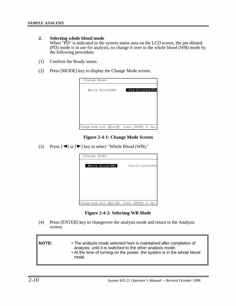
2. Selecting whole blood modeWhen "PD" is indicated in the system status area on the LCD screen, the pre-diluted(PD) mode is in use for analysis, so change it over to the whole blood (WB) mode bythe following procedure:
(1) Confirm the Ready status.
(2) Press [MODE] key to display the Change Mode screen.
*Change Mode*
Whole Blood(WB) Pre-Diluted(PD)Pre-Diluted(PD)
Change mode with [ ]or[ ]. Press [ENTER] to Set.
Figure 2-4-1: Change Mode Screen
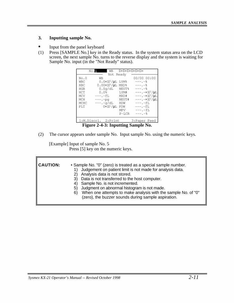
(3) Press [ ] or [ ] key to select "Whole Blood (WB)."
*Change Mode*
Whole Blood(WB) Pre-Diluted(PD)
Change mode with [ ]or[ ]. Press [ENTER] to Set.
Figure 2-4-2: Selecting WB Mode
(4) Press [ENTER] key to changeover the analysis mode and return to the Analysisscreen.
NOTE: • The analysis mode selected here is maintained after completion ofanalysis, until it is switched to the other analysis mode.
• At the time of turning-on the power, the system is in the whole bloodmode.
SAMPLE ANALYSIS
Sysmex KX-21 Operator’s Manual -- Revised October 1998 2-11
3. Inputting sample No.
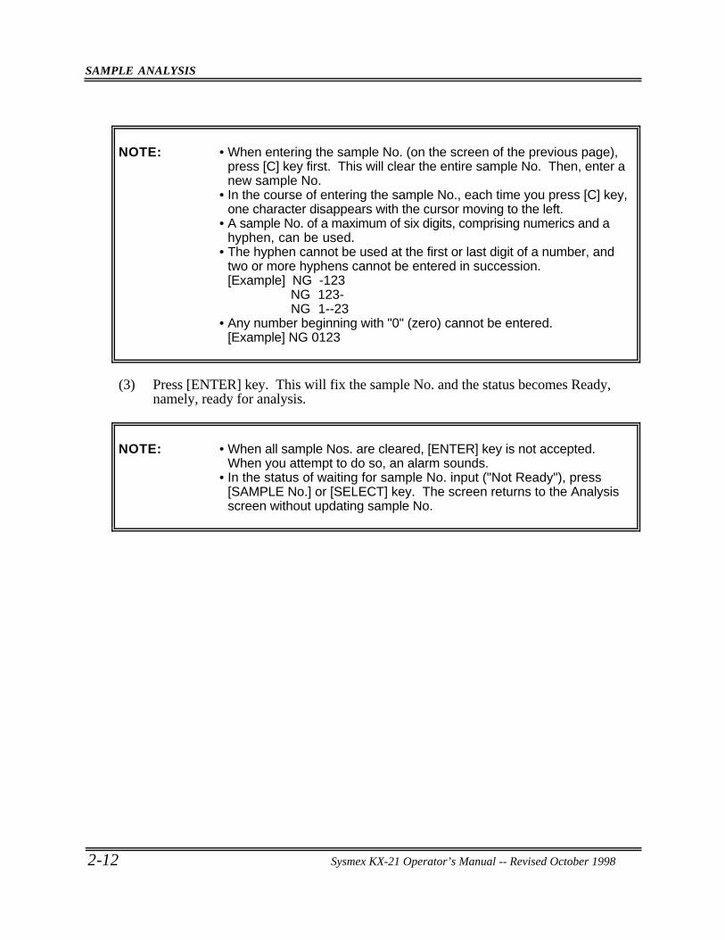
• Input from the panel keyboard(1) Press [SAMPLE No.] key in the Ready status. In the system status area on the LCD
screen, the next sample No. turns to the reverse display and the system is waiting forSample No. input (in the "Not Ready" status).
00/00 00:00No.0 WB
P-LCR ---.-%MPV ---.-fL
PLT 0×103/µL PDW ---.-fLMCHC ---.-g/dL RDW ---.-fLMCH ---.-pg NEUT# ---.-×103/µLMCV ---.-fL MXD# ---.-×103/µLHCT 0.0% LYM# ---.-×103/µLHGB 0.0g/dL NEUT% ---.-%RBC 0.00×10⁶/µL MXD% ---.-%WBC 0.0×10³/µL LYM% ---.-%
No.1 WB
1:M.Discri. 2:Print 3:Paper Feed
Not Ready
Figure 2-4-3: Inputting Sample No.
(2) The cursor appears under sample No. Input sample No. using the numeric keys.
[Example] Input of sample No. 5 Press [5] key on the numeric keys.
CAUTION: • Sample No. "0" (zero) is treated as a special sample number.1) Judgement on patient limit is not made for analysis data.2) Analysis data is not stored.3) Data is not transferred to the host computer.4) Sample No. is not incremented.5) Judgment on abnormal histogram is not made.6) When one attempts to make analysis with the sample No. of "0"
(zero), the buzzer sounds during sample aspiration.
SAMPLE ANALYSIS
2-12 Sysmex KX-21 Operator’s Manual -- Revised October 1998
NOTE: • When entering the sample No. (on the screen of the previous page),press [C] key first. This will clear the entire sample No. Then, enter anew sample No.
• In the course of entering the sample No., each time you press [C] key,one character disappears with the cursor moving to the left.
• A sample No. of a maximum of six digits, comprising numerics and ahyphen, can be used.
• The hyphen cannot be used at the first or last digit of a number, andtwo or more hyphens cannot be entered in succession.[Example] NG -123
NG 123- NG 1--23
• Any number beginning with "0" (zero) cannot be entered.[Example] NG 0123
(3) Press [ENTER] key. This will fix the sample No. and the status becomes Ready,namely, ready for analysis.
NOTE: • When all sample Nos. are cleared, [ENTER] key is not accepted.When you attempt to do so, an alarm sounds.
• In the status of waiting for sample No. input ("Not Ready"), press[SAMPLE No.] or [SELECT] key. The screen returns to the Analysisscreen without updating sample No.
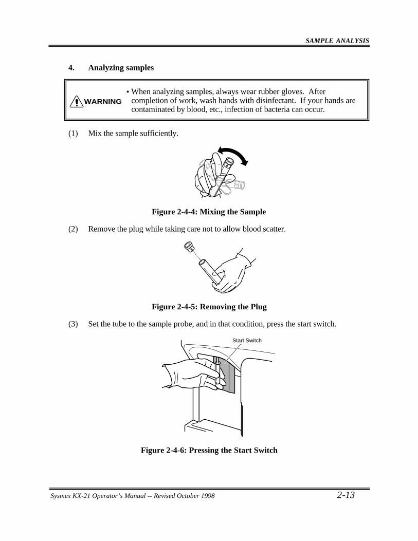
SAMPLE ANALYSIS
Sysmex KX-21 Operator’s Manual -- Revised October 1998 2-13
4. Analyzing samples
• When analyzing samples, always wear rubber gloves. Aftercompletion of work, wash hands with disinfectant. If your hands arecontaminated by blood, etc., infection of bacteria can occur.
(1) Mix the sample sufficiently.
Figure 2-4-4: Mixing the Sample
(2) Remove the plug while taking care not to allow blood scatter.
Figure 2-4-5: Removing the Plug
(3) Set the tube to the sample probe, and in that condition, press the start switch.
Start Switch
Figure 2-4-6: Pressing the Start Switch
WARNING
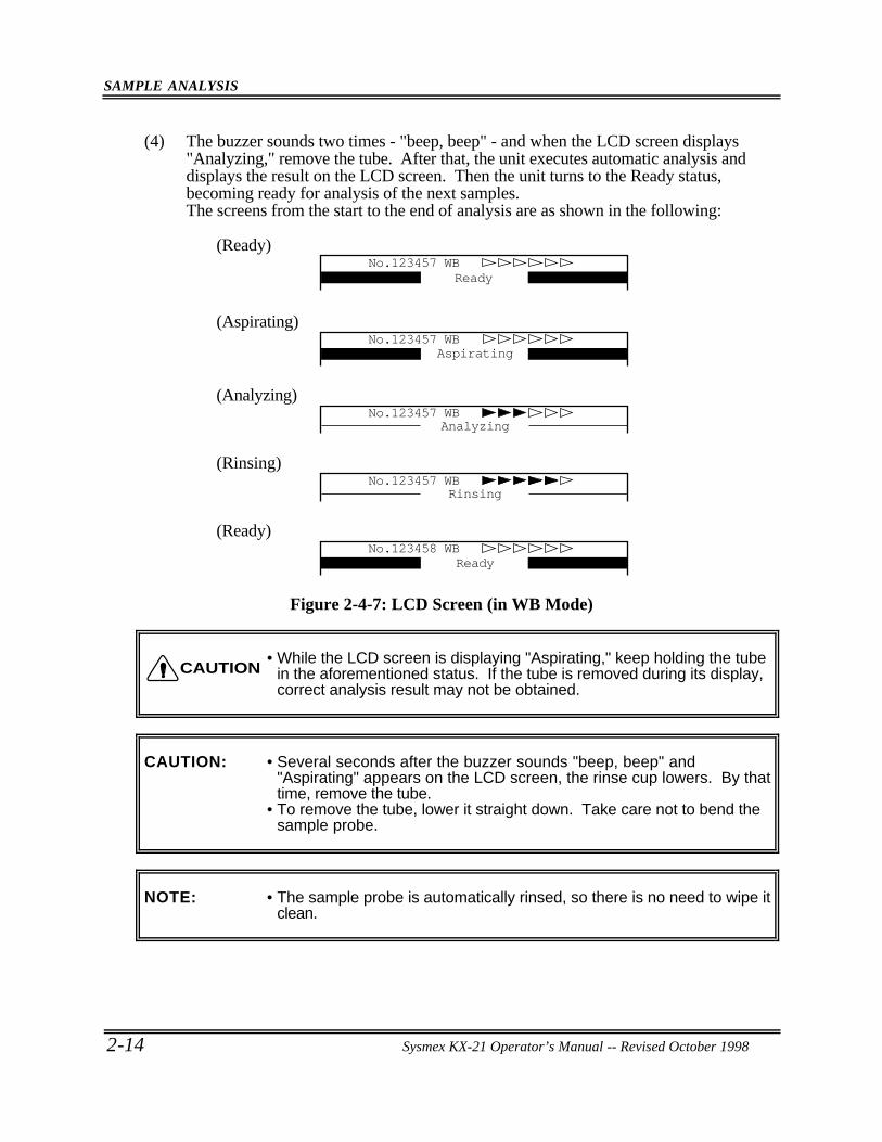
SAMPLE ANALYSIS
2-14 Sysmex KX-21 Operator’s Manual -- Revised October 1998
(4) The buzzer sounds two times - "beep, beep" - and when the LCD screen displays"Analyzing," remove the tube. After that, the unit executes automatic analysis anddisplays the result on the LCD screen. Then the unit turns to the Ready status,becoming ready for analysis of the next samples.The screens from the start to the end of analysis are as shown in the following:
(Ready)No.123457 WB
Ready
(Aspirating)No.123457 WB
Aspirating
(Analyzing)No.123457 WB
Analyzing
(Rinsing)No.123457 WB
Rinsing
(Ready)No.123458 WB
Ready
Figure 2-4-7: LCD Screen (in WB Mode)
• While the LCD screen is displaying "Aspirating," keep holding the tubein the aforementioned status. If the tube is removed during its display,correct analysis result may not be obtained.
CAUTION: • Several seconds after the buzzer sounds "beep, beep" and"Aspirating" appears on the LCD screen, the rinse cup lowers. By thattime, remove the tube.
• To remove the tube, lower it straight down. Take care not to bend thesample probe.
NOTE: • The sample probe is automatically rinsed, so there is no need to wipe itclean.
CAUTION
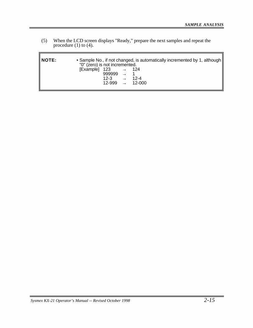
SAMPLE ANALYSIS
Sysmex KX-21 Operator’s Manual -- Revised October 1998 2-15
(5) When the LCD screen displays "Ready," prepare the next samples and repeat theprocedure (1) to (4).
NOTE: • Sample No., if not changed, is automatically incremented by 1, although"0" (zero) is not incremented.[Example] 123 → 124
999999 → 112-3 → 12-412-999 → 12-000
SAMPLE ANALYSIS
2-16 Sysmex KX-21 Operator’s Manual -- Revised October 1998
4 .2 Pre-Diluted (PD) Mode
In this mode, a sample is diluted into 1:26 before analysis. This mode is applied in analyzinga capillary blood collected from the earlobe or fingertip. Samples are processed by thefollowing steps:
1. Collecting and preparing samples2. Preparing analysis samples in PD mode (dilution of 1:26)3. Selecting Pre-Diluted mode4. Inputting sample No.5. Analyzing samples
1. Collecting and preparing samplesDilute samples to the ratio of 1:26 using CELLPACK dispensed beforehand incontainers.[Example]
20 µL of blood is diluted in 500 µL of CELLPACK.
• A capillary blood collected from the earlobe or fingertip is prone toplatelet agglutination, so dilute and analyze it within 30 minutes.Otherwise, correct analysis result may not be obtained.
• With a sample of blood collected from the earlobe or fingertip, blood cellcount is generally higher than normal, with lower reproducibility. Ifpossible, analyze the same diluted sample twice and compare theresults. When the blood collection tube containing a commercial anti-coagulant is used, there is a possibility that RBC hemolysis or plateletagglutination occurs depending on the types of anticoagulant, with aconsequent change in analysis result. As anti-coagulant, use EDTA-2K, EDTA-3K, or EDTA-2Na.
Tubes up to 80 mm in height should be used. The volume of sample is as follows:
Volume of whole blood required Approx. 20 µL or more
Volume of sample aspirated Approx. 200 µL
CAUTION
SAMPLE ANALYSIS
Sysmex KX-21 Operator’s Manual -- Revised October 1998 2-17
2. Preparing analysis samples in PD mode (1:26 Dilution)
(1) Clean a container such as erlenmeyer flask, beaker, etc. with CELLPACK and removeany dirt.
(2) Using a syringe, etc., take CELLPACK into a cleaned container.
(3) Using a 500 µL transfer pipette, dispense 500 µL of CELLPACK into a micro-tube.
(4) Using a capillary tube, etc., collect 20 µL of blood and dispense it into the micro-tube.
(5) Attach the cap and mix well.
• When preparing PD-mode analysis samples, always wear rubbergloves. After completion of work, wash hands with disinfectant. Ifyour hands are contaminated by blood, etc., infection of bacteria orthe like can occur.
• A 1:26 dilution sample is prone to platelet agglutination. So, analyzethe sample within 30minntes after blood dispensing and diluting. Ifdiluent is dispensed in advance, evaporation and dirt mixing will resultin errors in analysis values. Therefore prepare one sample at a time.
When preparing a 1:26 dilution sample, use the tools listed below:• Diluent (CELLPACK)• Micro-tube (MT-40, etc.)• Capillary tube• A 500 µL transfer pipette• A container, such as erlenmeyer flask or beaker• A syringe
WARNING
CAUTION
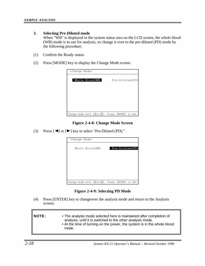
SAMPLE ANALYSIS
2-18 Sysmex KX-21 Operator’s Manual -- Revised October 1998
3. Selecting Pre-Diluted modeWhen "WB" is displayed in the system status area on the LCD screen, the whole blood(WB) mode is in use for analysis, so change it over to the pre-diluted (PD) mode bythe following procedure:
(1) Confirm the Ready status.
(2) Press [MODE] key to display the Change Mode screen.
*Change Mode*
Whole Blood(WB) Pre-Diluted(PD)
Change mode with [ ]or[ ]. Press [ENTER] to Set.
Figure 2-4-8: Change Mode Screen
(3) Press [ ] or [ ] key to select "Pre-Diluted (PD)."
*Change Mode*
Whole Blood(WB) Pre-Diluted(PD)Pre-Diluted(PD)
Change mode with [ ]or[ ]. Press [ENTER] to Set.
Figure 2-4-9: Selecting PD Mode
(4) Press [ENTER] key to changeover the analysis mode and return to the Analysisscreen.
NOTE: • The analysis mode selected here is maintained after completion ofanalysis, until it is switched to the other analysis mode.
• At the time of turning-on the power, the system is in the whole bloodmode.

SAMPLE ANALYSIS
Sysmex KX-21 Operator’s Manual -- Revised October 1998 2-19
4. Inputting sample No.
• Input from the panel keyboard(1) Press [SAMPLE No.] key in the Ready status. The next Sample No. in the system
status area on the LCD screen turns to the reverse display and the system waits forSample No. input (in the "Not Ready" status).
00/00 00:00No.0 PD
P-LCR ---.-%MPV ---.-fL
PLT 0×103/µL PDW ---.-fLMCHC ---.-g/dL RDW ---.-fLMCH ---.-pg NEUT# ---.-×103/µLMCV ---.-fL MXD# ---.-×103/µLHCT 0.0% LYM# ---.-×103/µLHGB 0.0g/dL NEUT% ---.-%RBC 0.00×10⁶/µL MXD% ---.-%WBC 0.0×10³/µL LYM% ---.-%
No.1 PD
1:M.Discri. 2:Print 3:Paper Feed
Not Ready
Figure 2-4-10: Inputting Sample No.
(2) The cursor appears under sample No. Input sample No. using the numeric keys.
[Example] Input of Sample No. 5 Press [5] key on the numeric keys.
CAUTION: • Sample No. "0" (zero) is treated as a special sample number.1) Judgement on patient limit is not made for analysis data.2) Analysis data is not stored.3) Data is not transferred to the host computer.4) Sample No. is not incremented.5) Judgment on abnormal histogram is not made.6) When one attempts to make analysis with the sample No. of "0"
(zero), the buzzer sounds during sample aspiration.
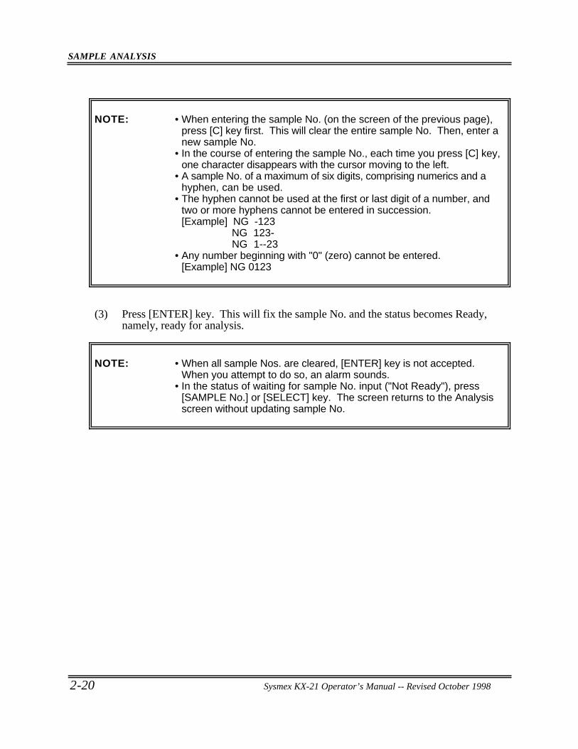
SAMPLE ANALYSIS
2-20 Sysmex KX-21 Operator’s Manual -- Revised October 1998
NOTE: • When entering the sample No. (on the screen of the previous page),press [C] key first. This will clear the entire sample No. Then, enter anew sample No.
• In the course of entering the sample No., each time you press [C] key,one character disappears with the cursor moving to the left.
• A sample No. of a maximum of six digits, comprising numerics and ahyphen, can be used.
• The hyphen cannot be used at the first or last digit of a number, andtwo or more hyphens cannot be entered in succession.[Example] NG -123
NG 123- NG 1--23
• Any number beginning with "0" (zero) cannot be entered.[Example] NG 0123
(3) Press [ENTER] key. This will fix the sample No. and the status becomes Ready,namely, ready for analysis.
NOTE: • When all sample Nos. are cleared, [ENTER] key is not accepted.When you attempt to do so, an alarm sounds.
• In the status of waiting for sample No. input ("Not Ready"), press[SAMPLE No.] or [SELECT] key. The screen returns to the Analysisscreen without updating sample No.
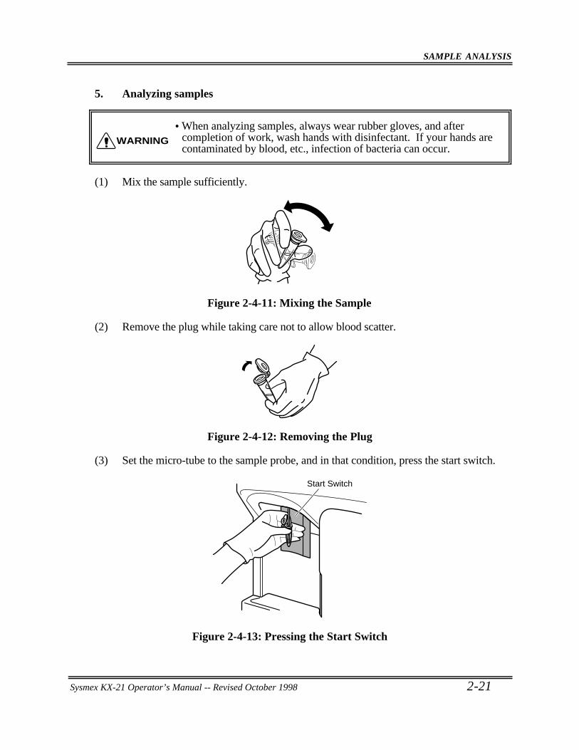
SAMPLE ANALYSIS
Sysmex KX-21 Operator’s Manual -- Revised October 1998 2-21
5. Analyzing samples
• When analyzing samples, always wear rubber gloves, and aftercompletion of work, wash hands with disinfectant. If your hands arecontaminated by blood, etc., infection of bacteria can occur.
(1) Mix the sample sufficiently.
Figure 2-4-11: Mixing the Sample
(2) Remove the plug while taking care not to allow blood scatter.
Figure 2-4-12: Removing the Plug
(3) Set the micro-tube to the sample probe, and in that condition, press the start switch.
Start Switch
Figure 2-4-13: Pressing the Start Switch
WARNING
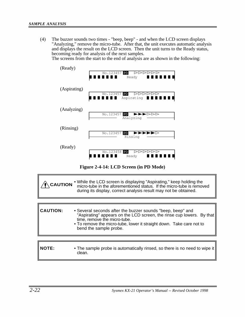
SAMPLE ANALYSIS
2-22 Sysmex KX-21 Operator’s Manual -- Revised October 1998
(4) The buzzer sounds two times - "beep, beep" - and when the LCD screen displays"Analyzing," remove the micro-tube. After that, the unit executes automatic analysisand displays the result on the LCD screen. Then the unit turns to the Ready status,becoming ready for analysis of the next samples.The screens from the start to the end of analysis are as shown in the following:
(Ready)No.123457 PD
Ready
(Aspirating)No.123457 PD
Aspirating
(Analyzing)No.123457 PD
Analyzing
(Rinsing)No.123457 PD
Rinsing
(Ready)No.123458 PD
Ready
Figure 2-4-14: LCD Screen (in PD Mode)
• While the LCD screen is displaying "Aspirating," keep holding themicro-tube in the aforementioned status. If the micro-tube is removedduring its display, correct analysis result may not be obtained.
CAUTION: • Several seconds after the buzzer sounds "beep, beep" and"Aspirating" appears on the LCD screen, the rinse cup lowers. By thattime, remove the micro-tube.
• To remove the micro-tube, lower it straight down. Take care not tobend the sample probe.
NOTE: • The sample probe is automatically rinsed, so there is no need to wipe itclean.
CAUTION
SAMPLE ANALYSIS
Sysmex KX-21 Operator’s Manual -- Revised October 1998 2-23
(5) When the LCD screen displays "Ready," prepare a next sample and repeat theprocedure (1) to (4).
NOTE: • Sample No., if not changed, is automatically incremented by 1, although"0" (zero) is not incremented.[Example] 123 → 124
999999 → 112-3 → 12-412-999 → 12-000
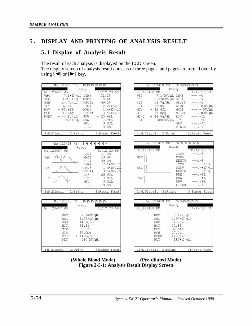
SAMPLE ANALYSIS
2-24 Sysmex KX-21 Operator’s Manual -- Revised October 1998
5 . DISPLAY AND PRINTING OF ANALYSIS RESULT
5 .1 Display of Analysis Result
The result of each analysis is displayed on the LCD screen.The display screen of analysis result consists of three pages, and pages are turned over byusing [ ] or [ ] key.
31/12 23:59No.123457 WB
P-LCR - 9.5%MPV 9.3fL
PLT 180×103/µL PDW - 7.9fLMCHC + 44.8g/dL RDW - 25.6fLMCH 37.0pg NEUT# 3.5×10³/µLMCV - 82.6fL MXD# 1.4×10³/µLHCT 32.8% LYM# 2.2×10³/µLHGB 14.7g/dL NEUT% 49.2%RBC 3.97×10⁶/µL MXD% 19.6%WBC 7.1×10³/µL LYM% 31.2%
No.123458 WBReady
1:M.Discri. 2:Print 3:Paper Feed
31/12 23:59No.123458 PD
P-LCR ---.-%MPV ---.-fL
PLT 180×103/µL PDW ---.-fLMCHC + 44.8g/dL RDW ---.-fLMCH 37.0pg NEUT# ---.-×103/µLMCV - 82.6fL MXD# ---.-×103/µLHCT 32.8% LYM# ---.-×103/µLHGB 14.7g/dL NEUT% ---.-%RBC 3.97×10⁶/µL MXD% ---.-%WBC 7.1×10³/µL LYM% ---.-%
No.123459 PDReady
1:M.Discri. 2:Print 3:Paper Feed
31/12 23:59No.123457 WB
P-LCR - 9.5%MPV 9.3fLPDW - 7.9fLRDW - 25.6fL
WBC
RBC
PLT
NEUT# 3.5×10³/µLMXD# 1.4×10³/µLLYM# 2.2×10³/µLNEUT% 49.2%MXD% 19.6%LYM% 31.2%
No.123458 WBReady
1:M.Discri. 2:Print 3:Paper Feed
31/12 23:59No.123458 PD
P-LCR ---.-%MPV ---.-fLPDW ---.-fLRDW ---.-fL
WBC
RBC
PLT
NEUT# ---.-×103/µLMXD# ---.-×103/µLLYM# ---.-×103/µLNEUT% ---.-%MXD% ---.-%LYM% ---.-%
No.123459 PDReady
1:M.Discri. 2:Print 3:Paper Feed
31/12 23:59No.123457 WB
PLT 180×103/µLMCHC + 44.8g/dLMCH 37.0pgMCV - 82.6fLHCT 32.8%HGB 14.7g/dLRBC 3.97×10⁶/µLWBC 7.1×10³/µL
No.123458 WBReady
1:M.Discri. 2:Print 3:Paper Feed
31/12 23:59No.123458 PD
PLT 180×103/µLMCHC + 44.8g/dLMCH 37.0pgMCV - 82.6fLHCT 32.8%HGB 14.7g/dLRBC 3.97×10⁶/µLWBC 7.1×10³/µL
No.123459 PDReady
1:M.Discri. 2:Print 3:Paper Feed
(Whole Blood Mode) (Pre-diluted Mode)Figure 2-5-1: Analysis Result Display Screen
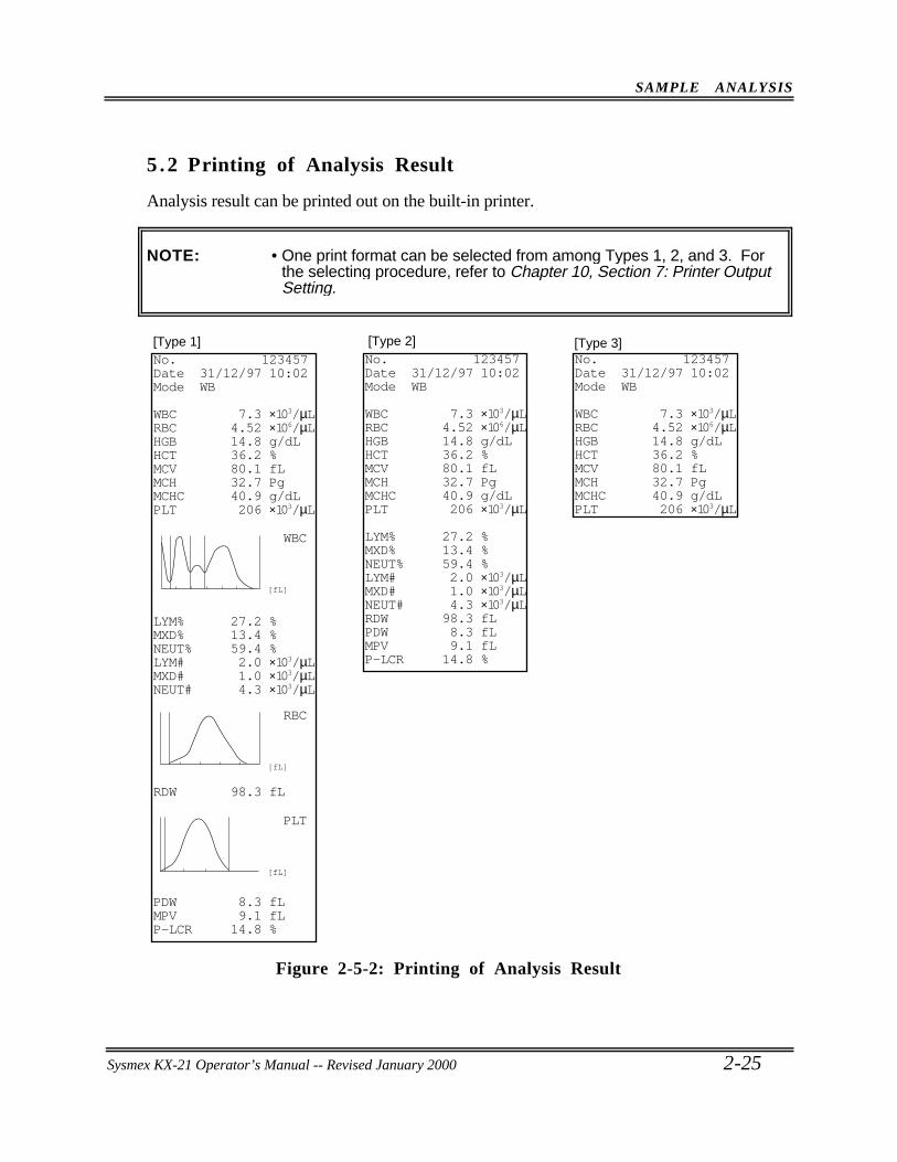
SAMPLE ANALYSIS
Sysmex KX-21 Operator’s Manual -- Revised October 2-25
5 .2 Printing of Analysis Result
Analysis result can be printed out on the built-in printer.
NOTE: • One print format can be selected from among Types 1, 2, and 3. Forthe selecting procedure, refer to Chapter 10, Section 7: Printer OutputSetting.
WBC
[fL]
RBC
[fL]
PLT
[fL]
[Type 1] [Type 2] [Type 3]No. 123457Date 31/12/97 10:02Mode WB
WBC 7.3 ×10³/µLRBC 4.52 ×10⁶/µLHGB 14.8 g/dLHCT 36.2 %MCV 80.1 fLMCH 32.7 PgMCHC 40.9 g/dLPLT 206 ×103/µL
LYM% 27.2 %MXD% 13.4 %NEUT% 59.4 %LYM# 2.0 ×10³/µLMXD# 1.0 ×10³/µLNEUT# 4.3 ×10³/µL
RDW 98.3 fL
PDW 8.3 fLMPV 9.1 fLP-LCR 14.8 %
No. 123457Date 31/12/97 10:02Mode WB
WBC 7.3 ×10³/µLRBC 4.52 ×10⁶/µLHGB 14.8 g/dLHCT 36.2 %MCV 80.1 fLMCH 32.7 PgMCHC 40.9 g/dLPLT 206 ×103/µL
LYM% 27.2 %MXD% 13.4 %NEUT% 59.4 %LYM# 2.0 ×10³/µLMXD# 1.0 ×10³/µLNEUT# 4.3 ×10³/µLRDW 98.3 fLPDW 8.3 fLMPV 9.1 fLP-LCR 14.8 %
No. 123457Date 31/12/97 10:02Mode WB
WBC 7.3 ×10³/µLRBC 4.52 ×10⁶/µLHGB 14.8 g/dLHCT 36.2 %MCV 80.1 fLMCH 32.7 PgMCHC 40.9 g/dLPLT 206 ×103/µL
Figure 2-5-2: Printing of Analysis Result
Sysmex KX-21 Operator’s Manual -- Revised January 2000
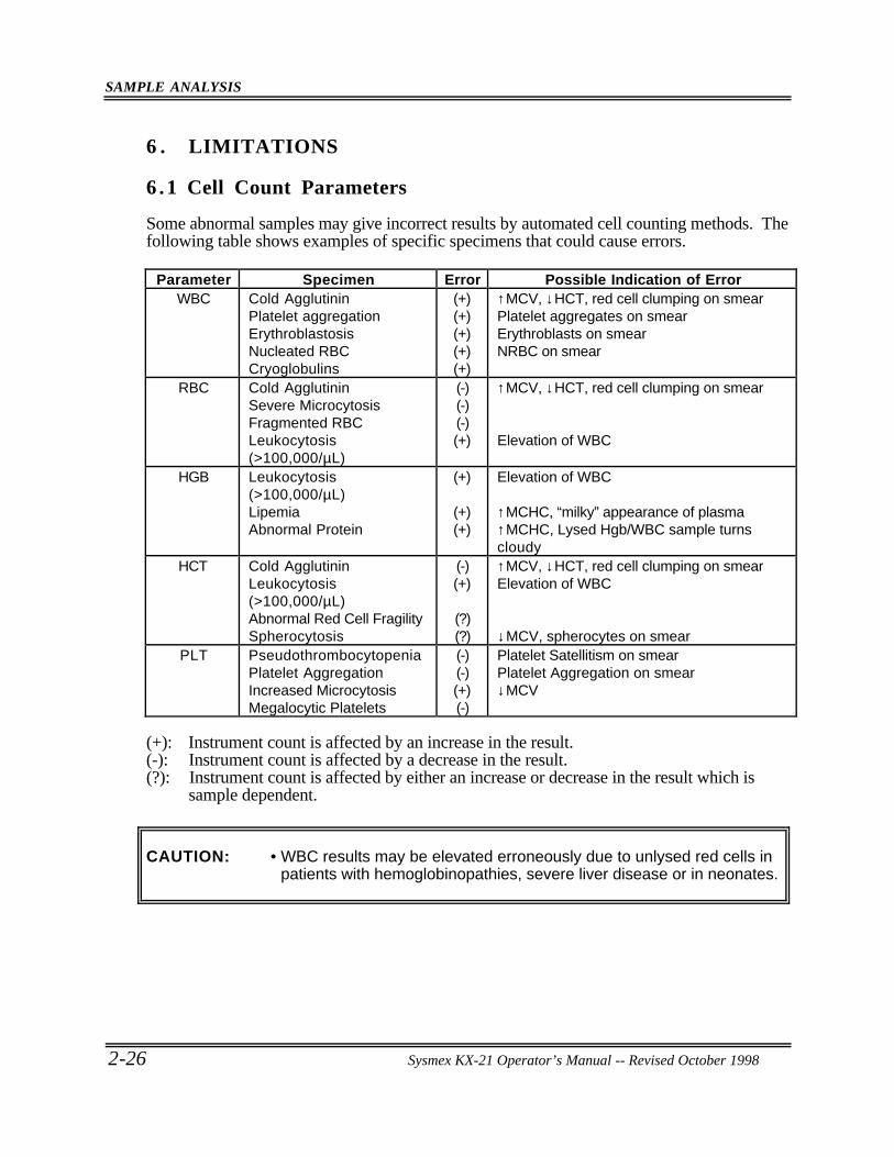
SAMPLE ANALYSIS
2-26 Sysmex KX-21 Operator’s Manual -- Revised October 1998
6 . LIMITATIONS
6 .1 Cell Count Parameters
Some abnormal samples may give incorrect results by automated cell counting methods. Thefollowing table shows examples of specific specimens that could cause errors.
Parameter Specimen Error Possible Indication of ErrorWBC Cold Agglutinin
Platelet aggregationErythroblastosisNucleated RBCCryoglobulins
(+)(+)(+)(+)(+)
↑MCV, ↓HCT, red cell clumping on smearPlatelet aggregates on smearErythroblasts on smearNRBC on smear
RBC Cold AgglutininSevere MicrocytosisFragmented RBCLeukocytosis(>100,000/µL)
(-)(-)(-)(+)
↑MCV, ↓HCT, red cell clumping on smear
Elevation of WBC
HGB Leukocytosis(>100,000/µL)LipemiaAbnormal Protein
(+)
(+)(+)
Elevation of WBC
↑MCHC, “milky” appearance of plasma↑MCHC, Lysed Hgb/WBC sample turnscloudy
HCT Cold AgglutininLeukocytosis(>100,000/µL)Abnormal Red Cell FragilitySpherocytosis
(-)(+)
(?)(?)
↑MCV, ↓HCT, red cell clumping on smearElevation of WBC
↓MCV, spherocytes on smearPLT Pseudothrombocytopenia
Platelet AggregationIncreased MicrocytosisMegalocytic Platelets
(-)(-)(+)(-)
Platelet Satellitism on smearPlatelet Aggregation on smear↓MCV
(+): Instrument count is affected by an increase in the result.(-): Instrument count is affected by a decrease in the result.(?): Instrument count is affected by either an increase or decrease in the result which is
sample dependent.
CAUTION: • WBC results may be elevated erroneously due to unlysed red cells inpatients with hemoglobinopathies, severe liver disease or in neonates.
SAMPLE ANALYSIS
Sysmex KX-21 Operator’s Manual -- Revised October 1998 2-27
6 .2 Limitation of Hemoglobin
1. Hemoglobin measurements may be falsely elevated due to the influences of abnormalsamples including leukocytosis above 100,000/µL, lipemia or abnormal proteins inblood plasma. The affect of lipemia and abnormal proteins may be removed by plasmareplacement or plasma blank procedures.
2. Performance specifications for hemoglobin results are assured only when instrumentenvironment and sample requirements are observed.
3. The hemoglobin method available for this analyzer cannot detect sulfhemoglobin,verdohemoglobin choleglobin or other unusual degradation products of hemoglobin.
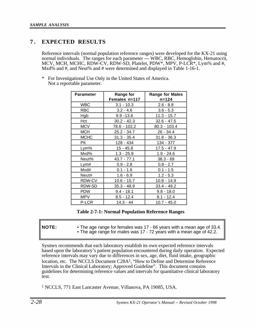
SAMPLE ANALYSIS
2-28 Sysmex KX-21 Operator’s Manual -- Revised October 1998
7 . EXPECTED RESULTS
Reference intervals (normal population reference ranges) were developed for the KX-21 usingnormal individuals. The ranges for each parameter --- WBC, RBC, Hemoglobin, Hematocrit,MCV, MCH, MCHC, RDW-CV, RDW-SD, Platelet, PDW*, MPV, P-LCR*, Lym% and #,Mxd% and #, and Neut% and # were determined and displayed in Table 1-16-1.
* For Investigational Use Only in the United States of America.Not a reportable parameter.
Parameter Range forFemales n=117
Range for Malesn=124
WBC 3.1 - 10.3 2.6 - 8.8RBC 3.2 - 4.6 3.6 - 5.3Hgb 9.9 -13.6 11.3 - 15.7Hct 30.2 - 42.3 32.6 - 47.5MCV 78.6 - 102.2 80.3 - 103.4MCH 25.2 - 34.7 26 - 34.4MCHC 31.3 - 35.4 31.8 - 36.3Plt 128 - 434 134 - 377Lym% 15 - 45.8 17.5 - 47.9Mxd% 1.3 - 25.9 1.9 - 24.6Neut% 43.7 - 77.1 38.3 - 69Lym# 0.9 - 2.8 0.8 - 2.7Mxd# 0.1 - 1.6 0.1 - 1.5Neut# 1.6 - 6.9 1.2 - 5.3RDW-CV 10.6 - 15.7 10.8 - 14.9RDW-SD 35.3 - 48.9 33.4 - 49.2PDW 9.4 - 18.1 9.8 - 18.0MPV 8.5 - 12.4 8.1 - 12.4P-LCR 14.3 - 44 10.7 - 45.0
Table 2-7-1: Normal Population Reference Ranges
NOTE: • The age range for females was 17 - 66 years with a mean age of 33.4.• The age range for males was 17 - 72 years with a mean age of 42.2.
Sysmex recommends that each laboratory establish its own expected reference intervalsbased upon the laboratory’s patient population encountered during daily operation. Expectedreference intervals may vary due to differences in sex, age, diet, fluid intake, geographiclocation, etc. The NCCLS Document C28A1, “How to Define and Determine ReferenceIntervals in the Clinical Laboratory; Approved Guideline”. This document containsguidelines for determining reference values and intervals for quantitative clinical laboratorytest.
1 NCCLS, 771 East Lancaster Avenue, Villanova, PA 19085, USA.
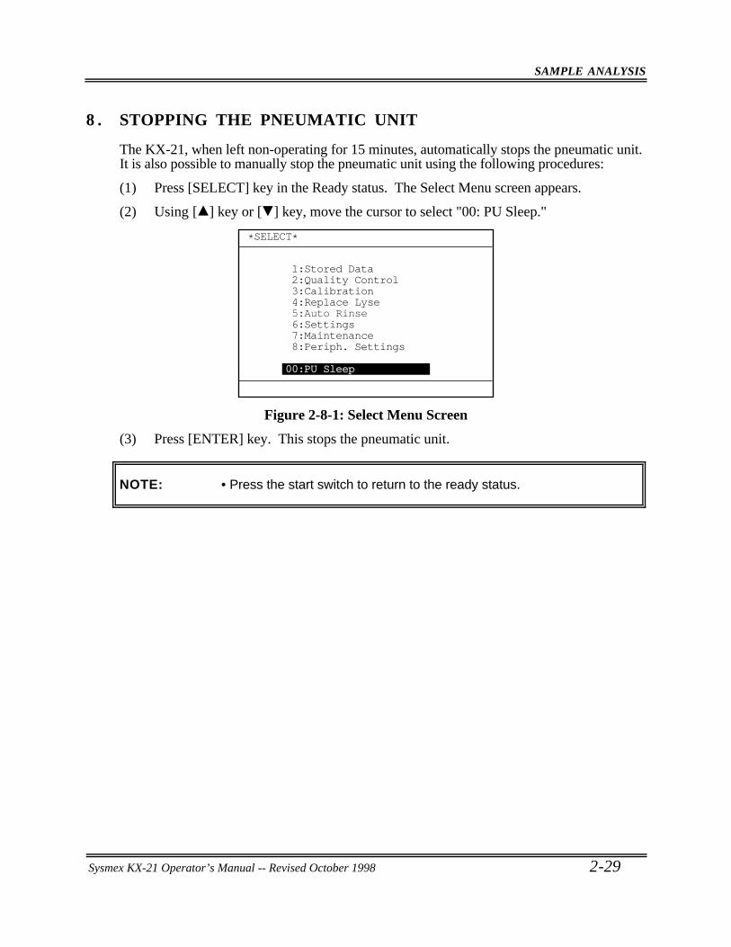
SAMPLE ANALYSIS
Sysmex KX-21 Operator’s Manual -- Revised October 1998 2-29
8 . STOPPING THE PNEUMATIC UNIT
The KX-21, when left non-operating for 15 minutes, automatically stops the pneumatic unit.It is also possible to manually stop the pneumatic unit using the following procedures:
(1) Press [SELECT] key in the Ready status. The Select Menu screen appears.
(2) Using [ ] key or [ ] key, move the cursor to select "00: PU Sleep."
*SELECT*
1:Stored Data2:Quality Control3:Calibration4:Replace Lyse5:Auto Rinse6:Settings7:Maintenance8:Periph. Settings
00:PU Sleep
Figure 2-8-1: Select Menu Screen
(3) Press [ENTER] key. This stops the pneumatic unit.
NOTE: • Press the start switch to return to the ready status.
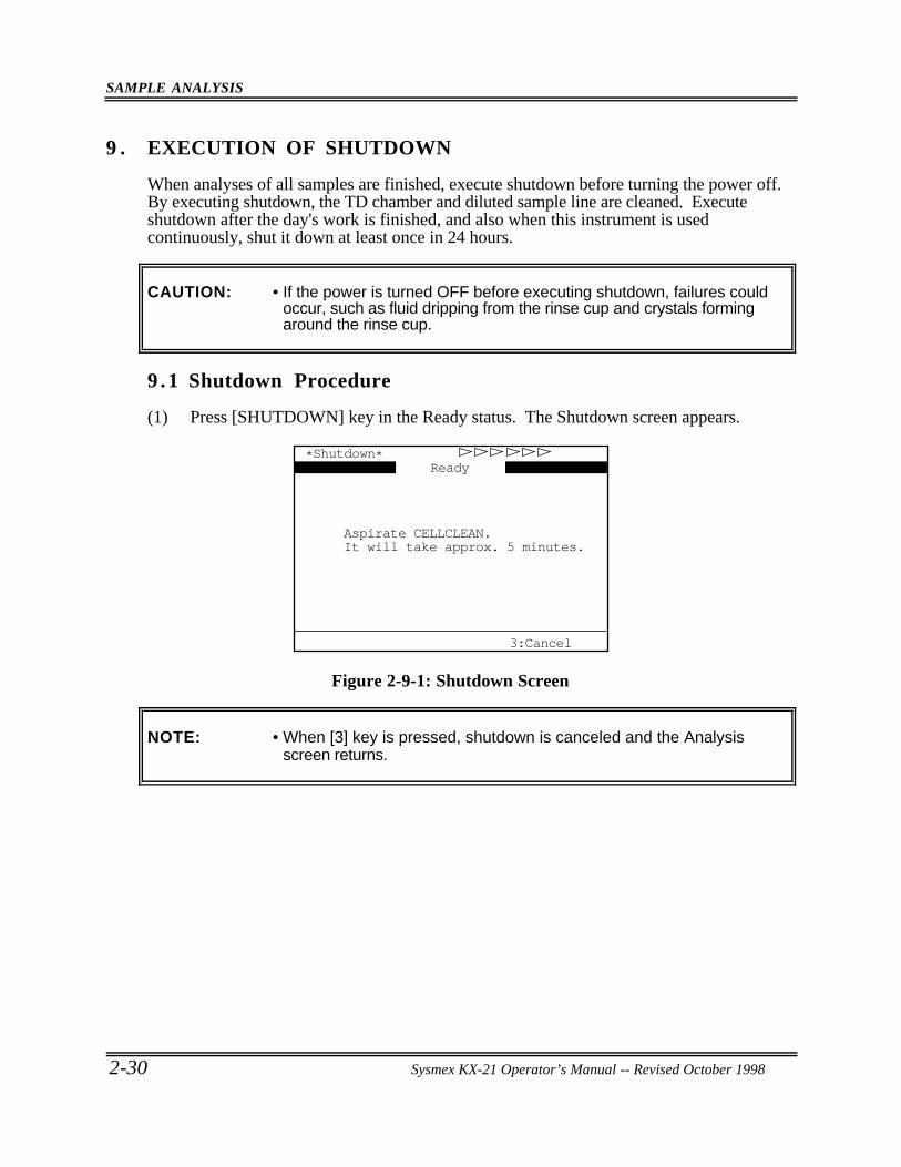
SAMPLE ANALYSIS
2-30 Sysmex KX-21 Operator’s Manual -- Revised October 1998
9 . EXECUTION OF SHUTDOWN
When analyses of all samples are finished, execute shutdown before turning the power off.By executing shutdown, the TD chamber and diluted sample line are cleaned. Executeshutdown after the day's work is finished, and also when this instrument is usedcontinuously, shut it down at least once in 24 hours.
CAUTION: • If the power is turned OFF before executing shutdown, failures couldoccur, such as fluid dripping from the rinse cup and crystals formingaround the rinse cup.
9 .1 Shutdown Procedure
(1) Press [SHUTDOWN] key in the Ready status. The Shutdown screen appears.
3:Cancel
*Shutdown*
Aspirate CELLCLEAN.It will take approx. 5 minutes.
Ready
Figure 2-9-1: Shutdown Screen
NOTE: • When [3] key is pressed, shutdown is canceled and the Analysisscreen returns.
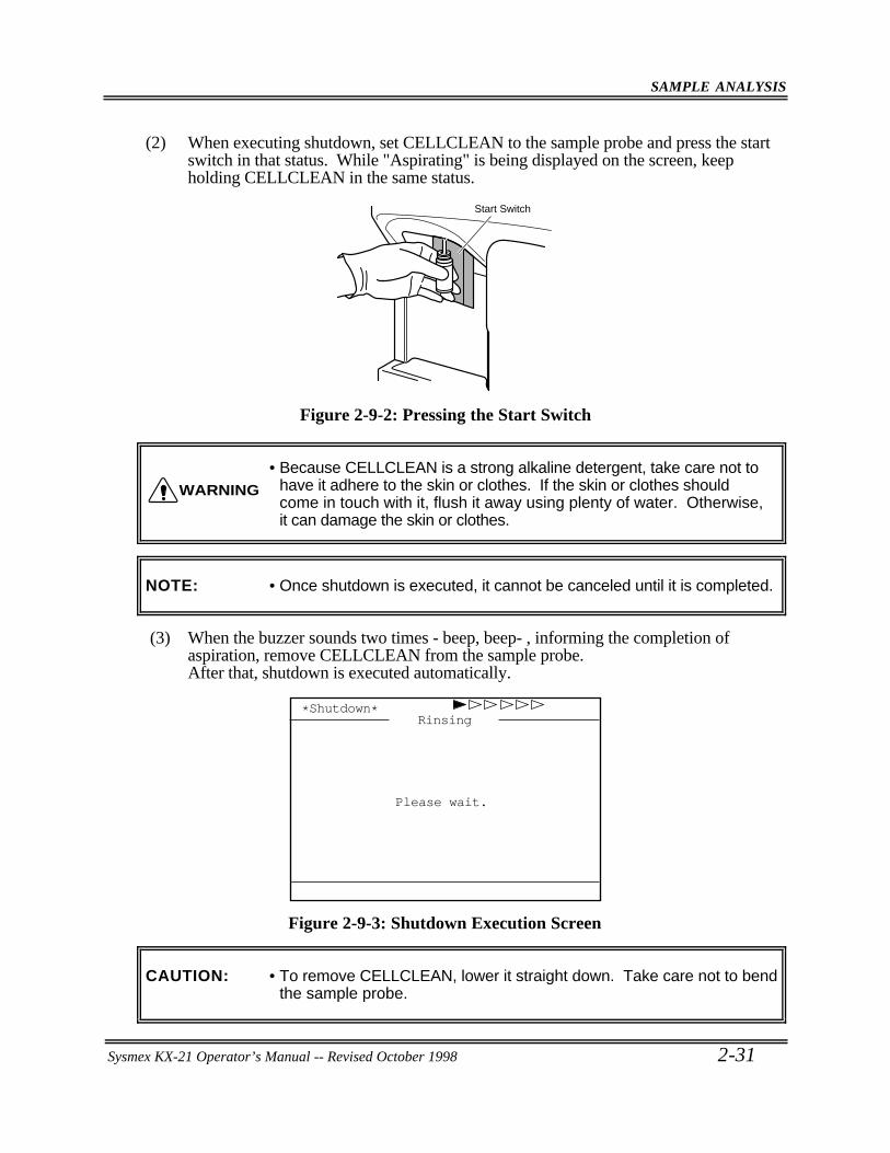
SAMPLE ANALYSIS
Sysmex KX-21 Operator’s Manual -- Revised October 1998 2-31
(2) When executing shutdown, set CELLCLEAN to the sample probe and press the startswitch in that status. While "Aspirating" is being displayed on the screen, keepholding CELLCLEAN in the same status.
Start Switch
Figure 2-9-2: Pressing the Start Switch
• Because CELLCLEAN is a strong alkaline detergent, take care not tohave it adhere to the skin or clothes. If the skin or clothes shouldcome in touch with it, flush it away using plenty of water. Otherwise,it can damage the skin or clothes.
NOTE: • Once shutdown is executed, it cannot be canceled until it is completed.
(3) When the buzzer sounds two times - beep, beep- , informing the completion ofaspiration, remove CELLCLEAN from the sample probe.After that, shutdown is executed automatically.
*Shutdown*
Please wait.
Rinsing
Figure 2-9-3: Shutdown Execution Screen
CAUTION: • To remove CELLCLEAN, lower it straight down. Take care not to bendthe sample probe.
WARNING
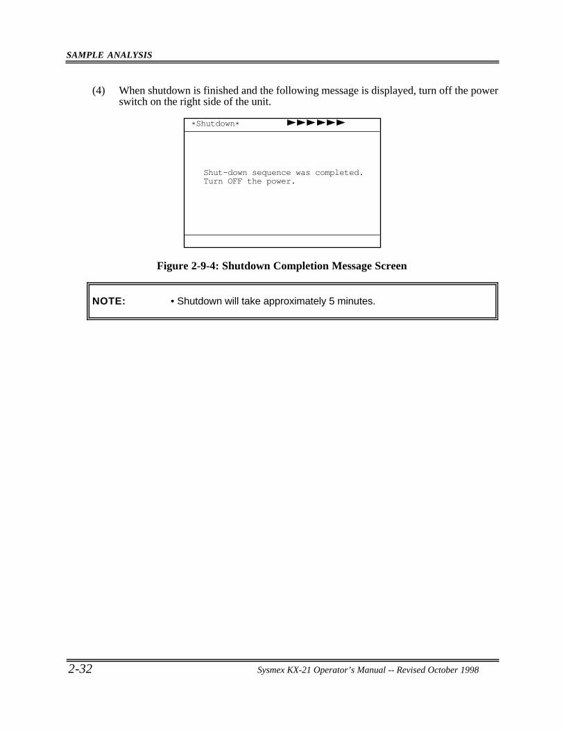
SAMPLE ANALYSIS
2-32 Sysmex KX-21 Operator’s Manual -- Revised October 1998
(4) When shutdown is finished and the following message is displayed, turn off the powerswitch on the right side of the unit.
Shut-down sequence was completed.Turn OFF the power.
*Shutdown*
Figure 2-9-4: Shutdown Completion Message Screen
NOTE: • Shutdown will take approximately 5 minutes.
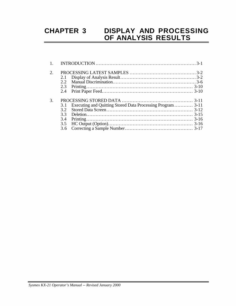
Sysmex KX-21 Operator’s Manual -- Revised January 2000
CHAPTER 3 DISPLAY AND PROCESSINGOF ANALYSIS RESULTS
1. INTRODUCTION ... . . . . . . . . . . . . . . . . . . . . . . . . . . . . . . . . . . . . . . . . . . . . . . . . . . . . . . . . . . . . . . 3-1
2. PROCESSING LATEST SAMPLES ... . . . . . . . . . . . . . . . . . . . . . . . . . . . . . . . . . . . . . . . . 3-22.1 Display of Analysis Result. . . . . . . . . . . . . . . . . . . . . . . . . . . . . . . . . . . . . . . . . . . . . . . . . 3-22.2 Manual Discrimination.. . . . . . . . . . . . . . . . . . . . . . . . . . . . . . . . . . . . . . . . . . . . . . . . . . . . . 3-62.3 Printing.. . . . . . . . . . . . . . . . . . . . . . . . . . . . . . . . . . . . . . . . . . . . . . . . . . . . . . . . . . . . . . . . . . . . 3-102.4 Print Paper Feed... . . . . . . . . . . . . . . . . . . . . . . . . . . . . . . . . . . . . . . . . . . . . . . . . . . . . . . . . 3-10
3. PROCESSING STORED DATA ... . . . . . . . . . . . . . . . . . . . . . . . . . . . . . . . . . . . . . . . . . . . 3-113.1 Executing and Quitting Stored Data Processing Program ... . . . . . . . . . 3-113.2 Stored Data Screen.. . . . . . . . . . . . . . . . . . . . . . . . . . . . . . . . . . . . . . . . . . . . . . . . . . . . . . . 3-123.3 Deletion.. . . . . . . . . . . . . . . . . . . . . . . . . . . . . . . . . . . . . . . . . . . . . . . . . . . . . . . . . . . . . . . . . . . . 3-153.4 Printing.. . . . . . . . . . . . . . . . . . . . . . . . . . . . . . . . . . . . . . . . . . . . . . . . . . . . . . . . . . . . . . . . . . . . 3-163.5 HC Output (Option).. . . . . . . . . . . . . . . . . . . . . . . . . . . . . . . . . . . . . . . . . . . . . . . . . . . . . . 3-163.6 Correcting a Sample Number.. . . . . . . . . . . . . . . . . . . . . . . . . . . . . . . . . . . . . . . . . . . 3-17
DISPLAY AND PROCESSING OF ANALYSIS RESULTS
Sysmex KX-21 Operator’s Manual -- Revised October 1998 3-1
1 . INTRODUCTION
This instrument displays analysis result and information that assists in breaking downanalysis result and outputs such data to external devices. This chapter describes theprocessing of analysis result, such as displaying latest or stored data on the screen oroutputting them to external devices. The gist of the contents is as follows:
Processing of Latest SamplesWhen analysis is finished, analysis result is displayed in three kinds of screens. The displaycontents of Analysis Result screen, what they mean, and how to process them are explainedhere.
Processing of Stored DataThe analysis data stored in the instrument can be read at anytime. Description is made on thedisplay contents of stored data, what they mean, deletion by marking, and output to externaldevices.
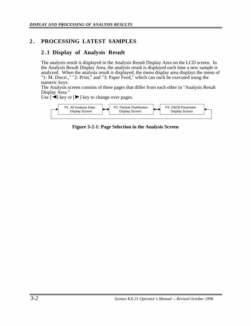
DISPLAY AND PROCESSING OF ANALYSIS RESULTS
3-2 Sysmex KX-21 Operator’s Manual -- Revised October 1998
2 . PROCESSING LATEST SAMPLES
2 .1 Display of Analysis Result
The analysis result is displayed in the Analysis Result Display Area on the LCD screen. Inthe Analysis Result Display Area, the analysis result is displayed each time a new sample isanalyzed. When the analysis result is displayed, the menu display area displays the menu of"1: M. Discri.," "2: Print," and "3: Paper Feed," which can each be executed using thenumeric keys.The Analysis screen consists of three pages that differ from each other in "Analysis ResultDisplay Area."Use [ ] key or [ ] key to change over pages.
P1. All Analysis Data Display Screen
P2. Particle Distribution Display Screen
P3. CBC8 Parameter Display Screen
Figure 3-2-1: Page Selection in the Analysis Screen
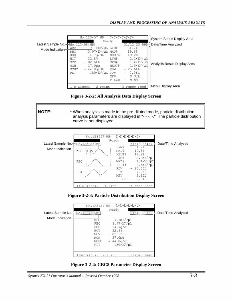
DISPLAY AND PROCESSING OF ANALYSIS RESULTS
Sysmex KX-21 Operator’s Manual -- Revised October 1998 3-3
System Status Display Area
Date/Time Analyzed Latest Sample No.
Mode Indication
Analysis Result Display Area
Menu Display Area
Ready
1:M.Discri. 2:Print 3:Paper Feed
31/12 23:59No.123458 WB
P-LCR - 9.5%MPV 9.3fL
PLT 180×103/µL PDW - 7.9fLMCHC + 44.8g/dL RDW - 25.6fLMCH 37.0pg NEUT# 3.5×10³/µLMCV - 82.6fL MXD# 1.4×10³/µLHCT 32.8% LYM# 2.2×10³/µLHGB 14.7g/dL NEUT% 49.2%RBC 3.97×10⁶/µL MXD% 19.6%WBC 7.1×10³/µL LYM% 31.2%
No.123457 WB
Figure 3-2-2: All Analysis Data Display Screen
NOTE: • When analysis is made in the pre-diluted mode, particle distributionanalysis parameters are displayed in "- - -. -." The particle distributioncurve is not displayed.
Date/Time AnalyzedLatest Sample No.
Mode Indication
31/12 23:59No.123458 WB
P-LCR - 9.5%MPV 9.3fLPDW - 7.9fLRDW - 25.6fL
WBC
RBC
PLT
NEUT# 3.5×10³/µLMXD# 1.4×10³/µLLYM# 2.2×10³/µLNEUT% 49.2%MXD% 19.6%LYM% 31.2%
No.123457 WBReady
1:M.Discri. 2:Print 3:Paper Feed
Figure 3-2-3: Particle Distribution Display Screen
Date/Time AnalyzedLatest Sample No.
Mode Indication
31/12 23:59No.123458 WB
PLT 180×103/µLMCHC + 44.8g/dLMCH 37.0pgMCV - 82.6fLHCT 32.8%HGB 14.7g/dLRBC 3.97×10⁶/µLWBC 7.1×10³/µL
No.123457 WBReady
1:M.Discri. 2:Print 3:Paper Feed
Figure 3-2-4: CBC8 Parameter Display Screen
DISPLAY AND PROCESSING OF ANALYSIS RESULTS
3-4 Sysmex KX-21 Operator’s Manual -- Revised October 1998
Display Contents of Analysis Data Display Screens1) System Status Display Area
This area displays the status of the instrument. For details, refer to Chapter 1, Section8.1: Contents of Display.
2) Latest Sample No.The latest sample No. is displayed.
3) Mode IndicationThe latest sample's analysis mode is displayed.The whole blood mode is displayed as "WB" and the pre-diluted mode as "PD."
4) Date/Time AnalyzedDate and time when analysis result was obtained are displayed.
5) Analysis DataThe analysis data of the following 18 parameters or part of them are displayeddepending on the screen:Analysis parameters (8): WBC, RBC, HGB, HCT, MCV, MCH, MCHC, PLTCalculation parameters (10): LYM%, MXD%, NEUT%,
LYM#, MXD#, NEUT#, RDW, PDW, MPV, P-LCR
NOTE: • As for RDW, either RDW-CV or RDW-SD is output.When shipped from factory, it is set at RDW-SDWhen you want to display RDW-CV, refer to Chapter 10, Section 2:System Setup.
• The instrument can be set to block out PDW and P-LCR. ContactSysmex service representative for assistance.
The marks to the left of analysis data indicate the following:1. ! : The data is out of the linearity limit.2. + : The data exceeds the upper Mark Limits.
- : The data exceeds the lower Mark Limits.3. * : The data is low in reliability.
NOTE: • The marks are added with the priority order of 1, 2, and 3.• The Mark Limits with "+" and "-" can be set by the customer. For
details, refer to Chapter 10, Section 4: Patient Limit.
DISPLAY AND PROCESSING OF ANALYSIS RESULTS
Sysmex KX-21 Operator’s Manual -- Revised October 1998 3-5
When an analysis error, etc. has caused errors in analysis data, the marks below areattached to the affected data:1. + + +. +: When data has exceeded the display range.2. * * *. *: When data could not be calculated due to instrument failure.3. - - -. -: When data could not be calculated due to data error.
NOTE: • When analysis is made in the pre-diluted mode, particle distributionanalysis parameters are displayed in "- - -. -."
When an error is found in particle distribution, a histogram error flag among thefollowing is displayed: 1. WL: Relative frequency of WBC-LD has exceeded the range. 2. WU: Relative frequency of WBC-UD has exceeded the range. 3. T1: T1 discriminator position cannot be determined. 4. T2: T2 discriminator position cannot be determined. 5. F1: Relative frequency of T1 has exceeded the range. 6. F2: Relative frequency of T1 or T2 has exceeded the range. 7. F3: Relative frequency of T2 has exceeded the range. 8. RL: Relative frequency of RBC-LD has exceeded the range. 9. RU: Relative frequency of RBC-UD has exceeded the range.10. DW: Distribution width cannot be calculated.11. MP: There are multiple peaks.12. PL: Relative frequency of PLT-LD has exceeded the range.13. PU: Relative frequency of PLT-UD has exceeded the range.14. AG: The particle count equal to or less than WBC-LD has exceeded the range.
NOTE: • When analysis is made in the pre-diluted mode, no flag is displayed toparticle distribution analysis parameters. For details, refer to Chapter 9,Section 6: Particle Distribution Analysis.
6) Menu Display AreaThe Menu is displayed in accordance with the screen. For details, refer to Chapter 1,Section 8.1: Contents of Display.
7) WBC Particle Distribution ChartThe WBC Particle distribution chart is displayed.
8) RBC Particle Distribution ChartThe RBC Particle distribution chart is displayed.
9) PLT Particle Distribution ChartThe PLT Particle distribution chart is displayed.
Sysmex KX-21 Operator’s Manual -- Revised December 1998
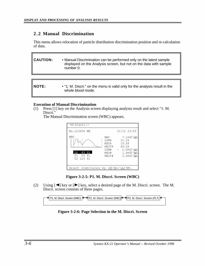
DISPLAY AND PROCESSING OF ANALYSIS RESULTS
3-6 Sysmex KX-21 Operator’s Manual -- Revised October 1998
2 .2 Manual Discrimination
This menu allows relocation of particle distribution discrimination position and re-calculationof data.
CAUTION: • Manual Discrimination can be performed only on the latest sampledisplayed on the Analysis screen, but not on the data with samplenumber 0.
NOTE: • "1: M. Discri." on the menu is valid only for the analysis result in thewhole blood mode.
Execution of Manual Discrimination(1) Press [1] key on the Analysis screen displaying analysis result and select "1: M.
Discri."The Manual Discrimination screen (WBC) appears.
31/12 23:59No.123458 WB
WBC
NEUT# 3.5×10³/µLMXD# 1.4×10³/µLLYM# - 2.0×10³/µLNEUT% 49.2%MXD% 19.6%LYM% 31.2%WBC 7.1×10³/µL
T2 123 fLT1 93 fL
*M.Discri.*
Select item/cursor by [ ][ ]/[ ][ ].
LD 43 fL
Figure 3-2-5: P1. M. Discri. Screen (WBC)
(2) Using [ ] key or [ ] key, select a desired page of the M. Discri. screen. The M.Discri. screen consists of three pages.
P1. M. Discri. Screen (WBC) P2. M. Discri. Screen (RBC) P3. M. Discri. Screen (PLT)
Figure 3-2-6: Page Selection in the M. Discri. Screen
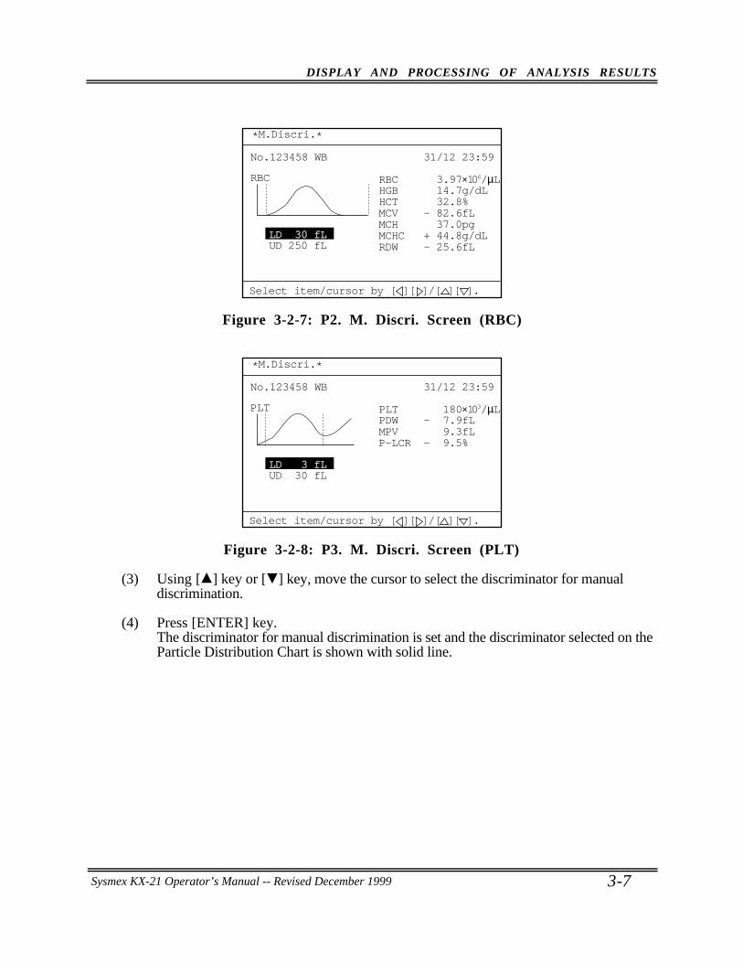
DISPLAY AND PROCESSING OF ANALYSIS RESULTS
Sysmex KX-21 Operator’s Manual -- Revised October 1998 3-7
31/12 23:59No.123458 WB
RBC
RDW - 25.6fLMCHC + 44.8g/dLMCH 37.0pgMCV - 82.6fLHCT 32.8%HGB 14.7g/dLRBC 3.97×10⁶/µL
UD 250 fL
*M.Discri.*
LD 30 fL
Select item/cursor by [ ][ ]/[ ][ ].
Figure 3-2-7: P2. M. Discri. Screen (RBC)
31/12 23:59No.123458 WB
PLT
P-LCR - 9.5%MPV 9.3fLPDW - 7.9fLPLT 180×103/µL
UD 30 fL
*M.Discri.*
LD 3 fL
Select item/cursor by [ ][ ]/[ ][ ].
Figure 3-2-8: P3. M. Discri. Screen (PLT)
(3) Using [ ] key or [ ] key, move the cursor to select the discriminator for manualdiscrimination.
(4) Press [ENTER] key.The discriminator for manual discrimination is set and the discriminator selected on theParticle Distribution Chart is shown with solid line.
Sysmex KX-21 Operator’s Manual -- Revised December 1999
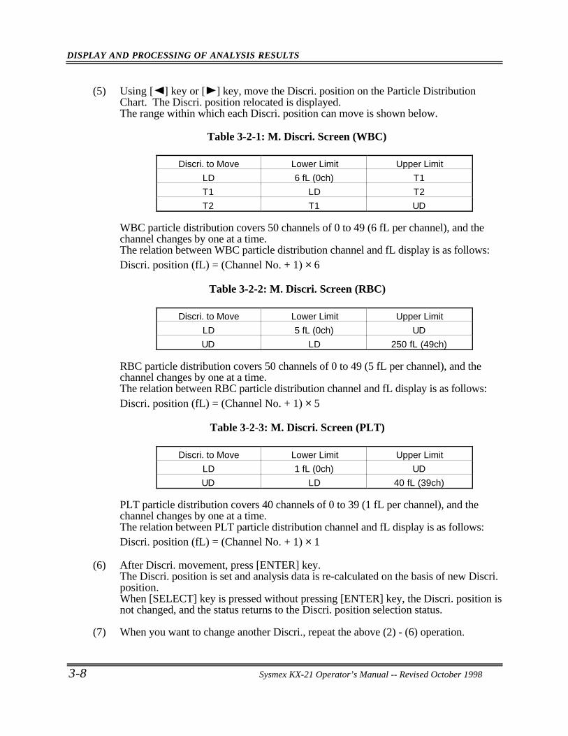
DISPLAY AND PROCESSING OF ANALYSIS RESULTS
3-8 Sysmex KX-21 Operator’s Manual -- Revised October 1998
(5) Using [ ] key or [ ] key, move the Discri. position on the Particle DistributionChart. The Discri. position relocated is displayed.The range within which each Discri. position can move is shown below.
Table 3-2-1: M. Discri. Screen (WBC)
Discri. to Move Lower Limit Upper Limit
LD 6 fL (0ch) T1
T1 LD T2
T2 T1 UD
WBC particle distribution covers 50 channels of 0 to 49 (6 fL per channel), and thechannel changes by one at a time.The relation between WBC particle distribution channel and fL display is as follows:Discri. position (fL) = (Channel No. + 1) × 6
Table 3-2-2: M. Discri. Screen (RBC)
Discri. to Move Lower Limit Upper Limit
LD 5 fL (0ch) UD
UD LD 250 fL (49ch)
RBC particle distribution covers 50 channels of 0 to 49 (5 fL per channel), and thechannel changes by one at a time.The relation between RBC particle distribution channel and fL display is as follows:Discri. position (fL) = (Channel No. + 1) × 5
Table 3-2-3: M. Discri. Screen (PLT)
Discri. to Move Lower Limit Upper Limit
LD 1 fL (0ch) UD
UD LD 40 fL (39ch)
PLT particle distribution covers 40 channels of 0 to 39 (1 fL per channel), and thechannel changes by one at a time.The relation between PLT particle distribution channel and fL display is as follows:Discri. position (fL) = (Channel No. + 1) × 1
(6) After Discri. movement, press [ENTER] key.The Discri. position is set and analysis data is re-calculated on the basis of new Discri.position.When [SELECT] key is pressed without pressing [ENTER] key, the Discri. position isnot changed, and the status returns to the Discri. position selection status.
(7) When you want to change another Discri., repeat the above (2) - (6) operation.
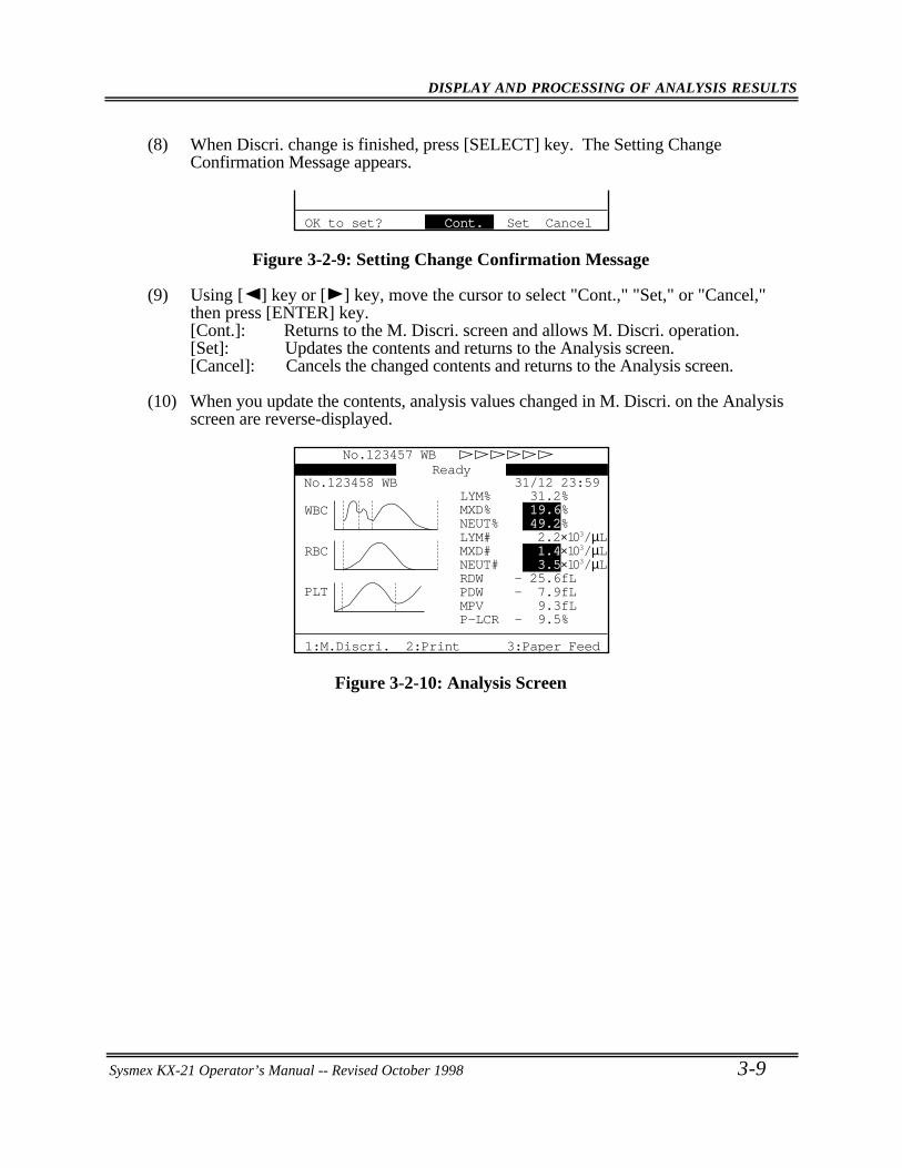
DISPLAY AND PROCESSING OF ANALYSIS RESULTS
Sysmex KX-21 Operator’s Manual -- Revised October 1998 3-9
(8) When Discri. change is finished, press [SELECT] key. The Setting ChangeConfirmation Message appears.
OK to set? Cont. Set Cancel
Figure 3-2-9: Setting Change Confirmation Message
(9) Using [ ] key or [ ] key, move the cursor to select "Cont.," "Set," or "Cancel,"then press [ENTER] key.[Cont.]: Returns to the M. Discri. screen and allows M. Discri. operation.[Set]: Updates the contents and returns to the Analysis screen.[Cancel]: Cancels the changed contents and returns to the Analysis screen.
(10) When you update the contents, analysis values changed in M. Discri. on the Analysisscreen are reverse-displayed.
31/12 23:59No.123458 WB
P-LCR - 9.5%MPV 9.3fLPDW - 7.9fLRDW - 25.6fL
WBC
RBC
PLT
NEUT# 3.5×10³/µLMXD# 1.4×10³/µLLYM# 2.2×10³/µLNEUT% 49.2%MXD% 19.6%LYM% 31.2%
No.123457 WBReady
1:M.Discri. 2:Print 3:Paper Feed
Figure 3-2-10: Analysis Screen
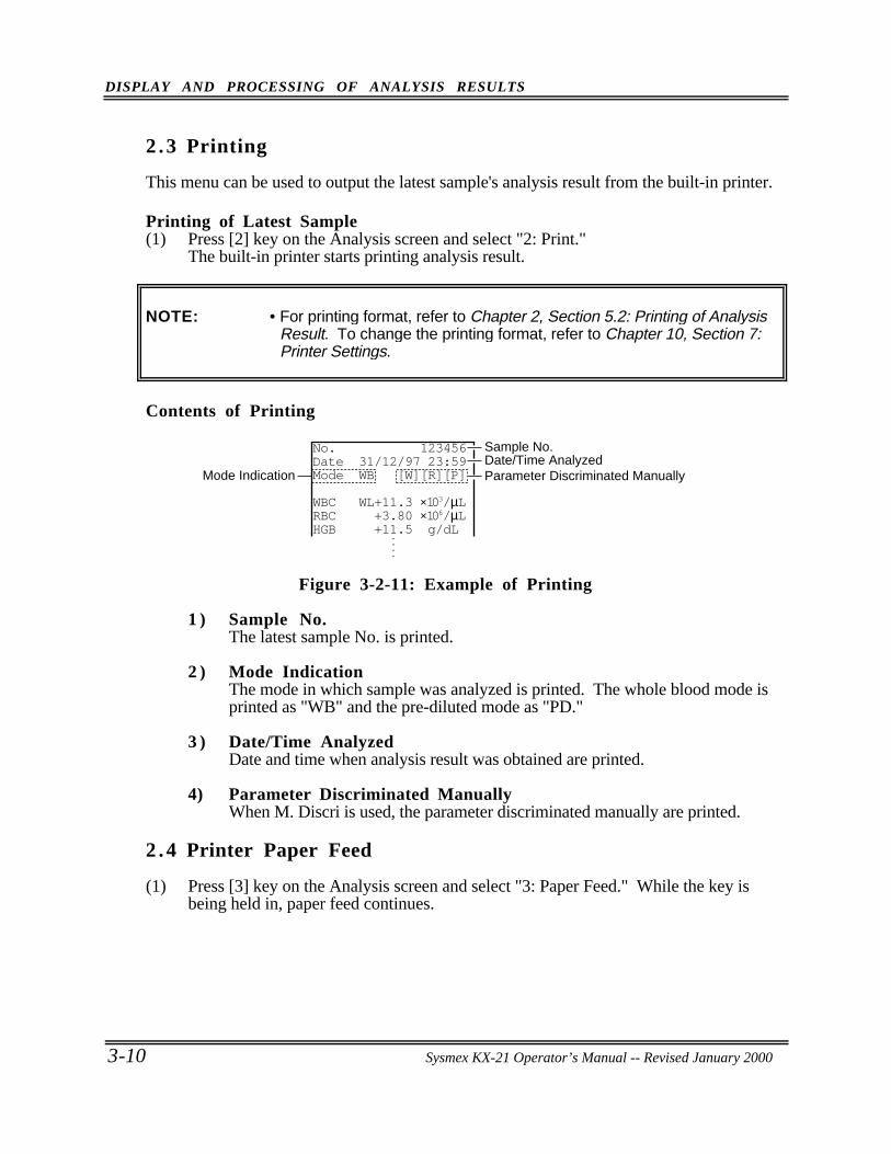
DISPLAY AND PROCESSING OF ANALYSIS RESULTS
3-10 Sysmex KX-21 Operator’s Manual -- Revised October 1998
2 .3 Printing
This menu can be used to output the latest sample's analysis result from the built-in printer.
Printing of Latest Sample(1) Press [2] key on the Analysis screen and select "2: Print."
The built-in printer starts printing analysis result.
NOTE: • For printing format, refer to Chapter 2, Section 5.2: Printing of AnalysisResult. To change the printing format, refer to Chapter 10, Section 7:Printer Settings.
Contents of Printing
Parameter Discriminated ManuallyMode IndicationDate/Time AnalyzedSample No.
• •
• •
No. 123456Date 31/12/97 23:59Mode WB [W][R][P]
WBC WL+11.3 ×10³/µLRBC +3.80 ×10⁶/µLHGB +11.5 g/dL
Figure 3-2-11: Example of Printing
1 ) Sample No.The latest sample No. is printed.
2 ) Mode IndicationThe mode in which sample was analyzed is printed. The whole blood mode isprinted as "WB" and the pre-diluted mode as "PD."
3 ) Date/Time AnalyzedDate and time when analysis result was obtained are printed.
4) Parameter Discriminated ManuallyWhen M. Discri is used, the parameter discriminated manually are printed.
2 .4 Printer Paper Feed
(1) Press [3] key on the Analysis screen and select "3: Paper Feed." While the key isbeing held in, paper feed continues.
Sysmex KX-21 Operator’s Manual -- Revised January 2000
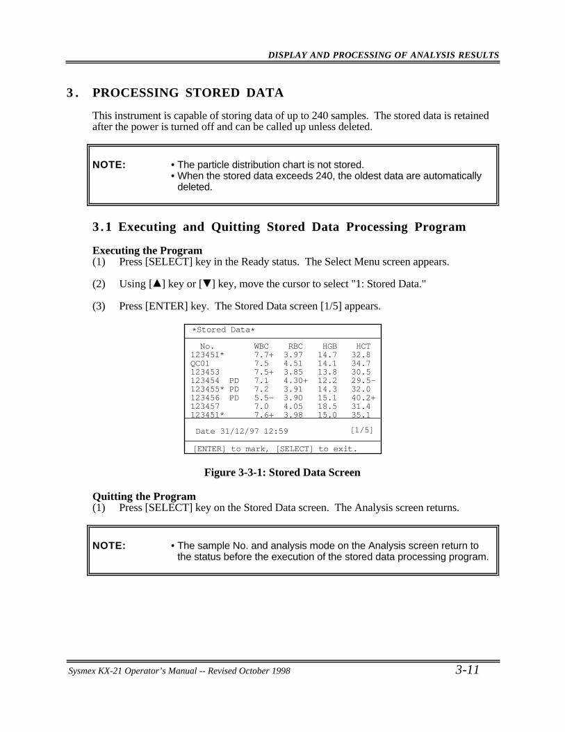
DISPLAY AND PROCESSING OF ANALYSIS RESULTS
Sysmex KX-21 Operator’s Manual -- Revised October 1998 3-11
3 . PROCESSING STORED DATA
This instrument is capable of storing data of up to 240 samples. The stored data is retainedafter the power is turned off and can be called up unless deleted.
NOTE: • The particle distribution chart is not stored.• When the stored data exceeds 240, the oldest data are automatically
deleted.
3 .1 Executing and Quitting Stored Data Processing Program
Executing the Program(1) Press [SELECT] key in the Ready status. The Select Menu screen appears.
(2) Using [ ] key or [ ] key, move the cursor to select "1: Stored Data."
(3) Press [ENTER] key. The Stored Data screen [1/5] appears.
No.123451* QC01 123453 123454 PD123455* PD123456 PD123457 123451*
Date 31/12/97 12:59 [1/5]
WBC 7.7+ 7.5 7.5+ 7.1 7.2 5.5- 7.0 7.6+
RBC 3.97 4.51 3.85 4.30+ 3.91 3.90 4.05 3.98
HGB 14.7 14.1 13.8 12.2 14.3 15.1 18.5 15.0
HCT 32.8 34.7 30.5 29.5- 32.0 40.2+ 31.4 35.1
*Stored Data*
[ENTER] to mark, [SELECT] to exit.
Figure 3-3-1: Stored Data Screen
Quitting the Program(1) Press [SELECT] key on the Stored Data screen. The Analysis screen returns.
NOTE: • The sample No. and analysis mode on the Analysis screen return tothe status before the execution of the stored data processing program.
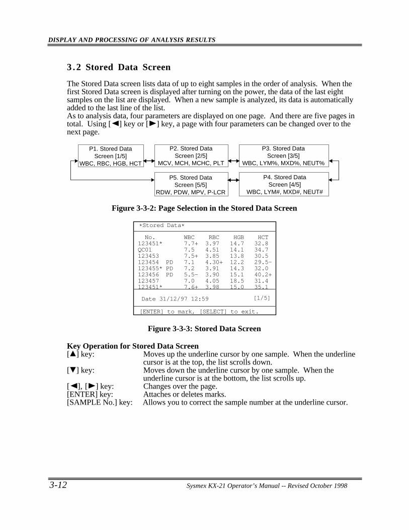
DISPLAY AND PROCESSING OF ANALYSIS RESULTS
3-12 Sysmex KX-21 Operator’s Manual -- Revised October 1998
3 .2 Stored Data Screen
The Stored Data screen lists data of up to eight samples in the order of analysis. When thefirst Stored Data screen is displayed after turning on the power, the data of the last eightsamples on the list are displayed. When a new sample is analyzed, its data is automaticallyadded to the last line of the list.As to analysis data, four parameters are displayed on one page. And there are five pages intotal. Using [ ] key or [ ] key, a page with four parameters can be changed over to thenext page.
P2. Stored DataScreen [2/5]
MCV, MCH, MCHC, PLT
P3. Stored DataScreen [3/5]
WBC, LYM%, MXD%, NEUT%
P5. Stored DataScreen [5/5]
RDW, PDW, MPV, P-LCR
P4. Stored DataScreen [4/5]
WBC, LYM#, MXD#, NEUT#
P1. Stored DataScreen [1/5]
WBC, RBC, HGB, HCT
Figure 3-3-2: Page Selection in the Stored Data Screen
No.123451* QC01 123453 123454 PD123455* PD123456 PD123457 123451*
Date 31/12/97 12:59 [1/5]
WBC 7.7+ 7.5 7.5+ 7.1 7.2 5.5- 7.0 7.6+
RBC 3.97 4.51 3.85 4.30+ 3.91 3.90 4.05 3.98
HGB 14.7 14.1 13.8 12.2 14.3 15.1 18.5 15.0
HCT 32.8 34.7 30.5 29.5- 32.0 40.2+ 31.4 35.1
*Stored Data*
[ENTER] to mark, [SELECT] to exit.
Figure 3-3-3: Stored Data Screen
Key Operation for Stored Data Screen[ ] key: Moves up the underline cursor by one sample. When the underline
cursor is at the top, the list scrolls down.[ ] key: Moves down the underline cursor by one sample. When the
underline cursor is at the bottom, the list scrolls up.[ ], [ ] key: Changes over the page.[ENTER] key: Attaches or deletes marks.[SAMPLE No.] key: Allows you to correct the sample number at the underline cursor.
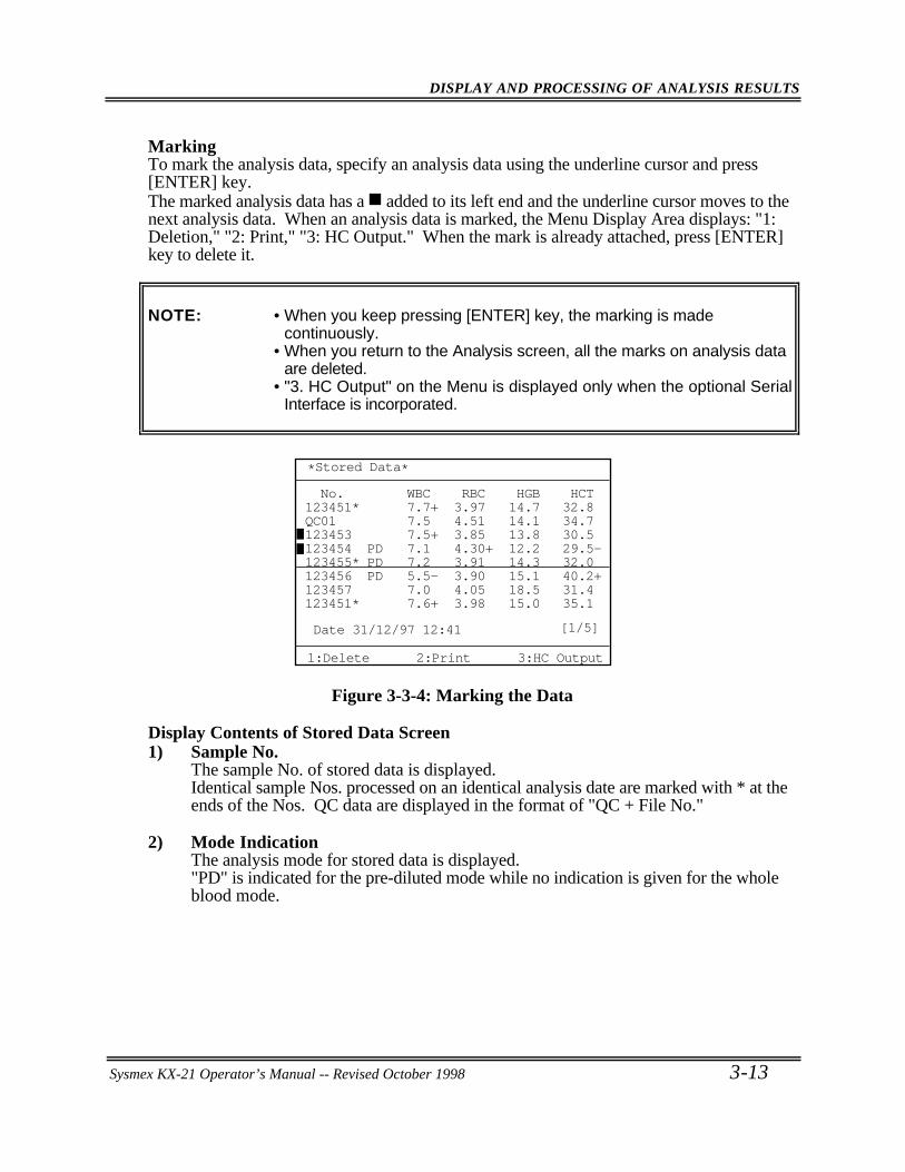
DISPLAY AND PROCESSING OF ANALYSIS RESULTS
Sysmex KX-21 Operator’s Manual -- Revised October 1998 3-13
MarkingTo mark the analysis data, specify an analysis data using the underline cursor and press[ENTER] key.The marked analysis data has a added to its left end and the underline cursor moves to thenext analysis data. When an analysis data is marked, the Menu Display Area displays: "1:Deletion," "2: Print," "3: HC Output." When the mark is already attached, press [ENTER]key to delete it.
NOTE: • When you keep pressing [ENTER] key, the marking is madecontinuously.
• When you return to the Analysis screen, all the marks on analysis dataare deleted.
• "3. HC Output" on the Menu is displayed only when the optional SerialInterface is incorporated.
No.123451* QC01 123453 123454 PD123455* PD123456 PD123457 123451*
Date 31/12/97 12:41 [1/5]
WBC 7.7+ 7.5 7.5+ 7.1 7.2 5.5- 7.0 7.6+
RBC 3.97 4.51 3.85 4.30+ 3.91 3.90 4.05 3.98
HGB 14.7 14.1 13.8 12.2 14.3 15.1 18.5 15.0
HCT 32.8 34.7 30.5 29.5- 32.0 40.2+ 31.4 35.1
*Stored Data*
1:Delete 2:Print 3:HC Output
Figure 3-3-4: Marking the Data
Display Contents of Stored Data Screen1) Sample No.
The sample No. of stored data is displayed.Identical sample Nos. processed on an identical analysis date are marked with * at theends of the Nos. QC data are displayed in the format of "QC + File No."
2) Mode IndicationThe analysis mode for stored data is displayed."PD" is indicated for the pre-diluted mode while no indication is given for the wholeblood mode.
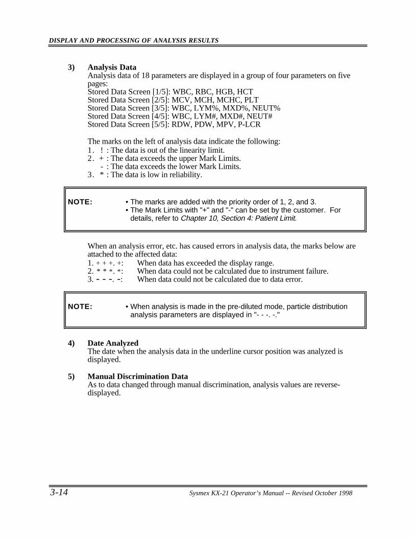
DISPLAY AND PROCESSING OF ANALYSIS RESULTS
3-14 Sysmex KX-21 Operator’s Manual -- Revised October 1998
3) Analysis DataAnalysis data of 18 parameters are displayed in a group of four parameters on fivepages:Stored Data Screen [1/5]: WBC, RBC, HGB, HCTStored Data Screen [2/5]: MCV, MCH, MCHC, PLTStored Data Screen [3/5]: WBC, LYM%, MXD%, NEUT%Stored Data Screen [4/5]: WBC, LYM#, MXD#, NEUT#Stored Data Screen [5/5]: RDW, PDW, MPV, P-LCR
The marks on the left of analysis data indicate the following:1. ! : The data is out of the linearity limit.2. + : The data exceeds the upper Mark Limits.
- : The data exceeds the lower Mark Limits.3. * : The data is low in reliability.
NOTE: • The marks are added with the priority order of 1, 2, and 3.• The Mark Limits with "+" and "-" can be set by the customer. For
details, refer to Chapter 10, Section 4: Patient Limit.
When an analysis error, etc. has caused errors in analysis data, the marks below areattached to the affected data:1. + + +. +: When data has exceeded the display range.2. * * *. *: When data could not be calculated due to instrument failure.3. - - -. -: When data could not be calculated due to data error.
NOTE: • When analysis is made in the pre-diluted mode, particle distributionanalysis parameters are displayed in "- - -. -."
4) Date AnalyzedThe date when the analysis data in the underline cursor position was analyzed isdisplayed.
5) Manual Discrimination DataAs to data changed through manual discrimination, analysis values are reverse-displayed.
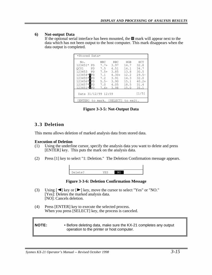
DISPLAY AND PROCESSING OF ANALYSIS RESULTS
Sysmex KX-21 Operator’s Manual -- Revised October 1998 3-15
6) Not-output DataIf the optional serial interface has been mounted, the mark will appear next to thedata which has not been output to the host computer. This mark disappears when thedata output is completed.
No.123451* PDQC01 PD123453 PD123454*HPD123455*HPD123456*HPD123457*HPD123451*HPD
Date 31/12/99 12:59 [1/5]
WBC 7.7+ 7.5 7.5+ 7.1 7.2 5.5- 7.0 7.6+
RBC 3.97 4.51 3.85 4.30+ 3.91 3.90 4.05 3.98
HGB 14.7 14.1 13.8 12.2 14.3 15.1 18.5 15.0
HCT 32.8 34.7 30.5 29.5- 32.0 40.2+ 31.4 35.1
*Stored Data*
[ENTER] to mark, [SELECT] to exit.
Figure 3-3-5: Not-Output Data
3 .3 Deletion
This menu allows deletion of marked analysis data from stored data.
Execution of Deletion(1) Using the underline cursor, specify the analysis data you want to delete and press
[ENTER] key. This puts the mark on the analysis data.
(2) Press [1] key to select "1: Deletion." The Deletion Confirmation message appears.
Delete? YES NO
Figure 3-3-6: Deletion Confirmation Message
(3) Using [ ] key or [ ] key, move the cursor to select "Yes" or "NO."[Yes]: Deletes the marked analysis data.[NO]: Cancels deletion.
(4) Press [ENTER] key to execute the selected process.When you press [SELECT] key, the process is canceled.
NOTE: • Before deleting data, make sure the KX-21 completes any outputoperation to the printer or host computer.
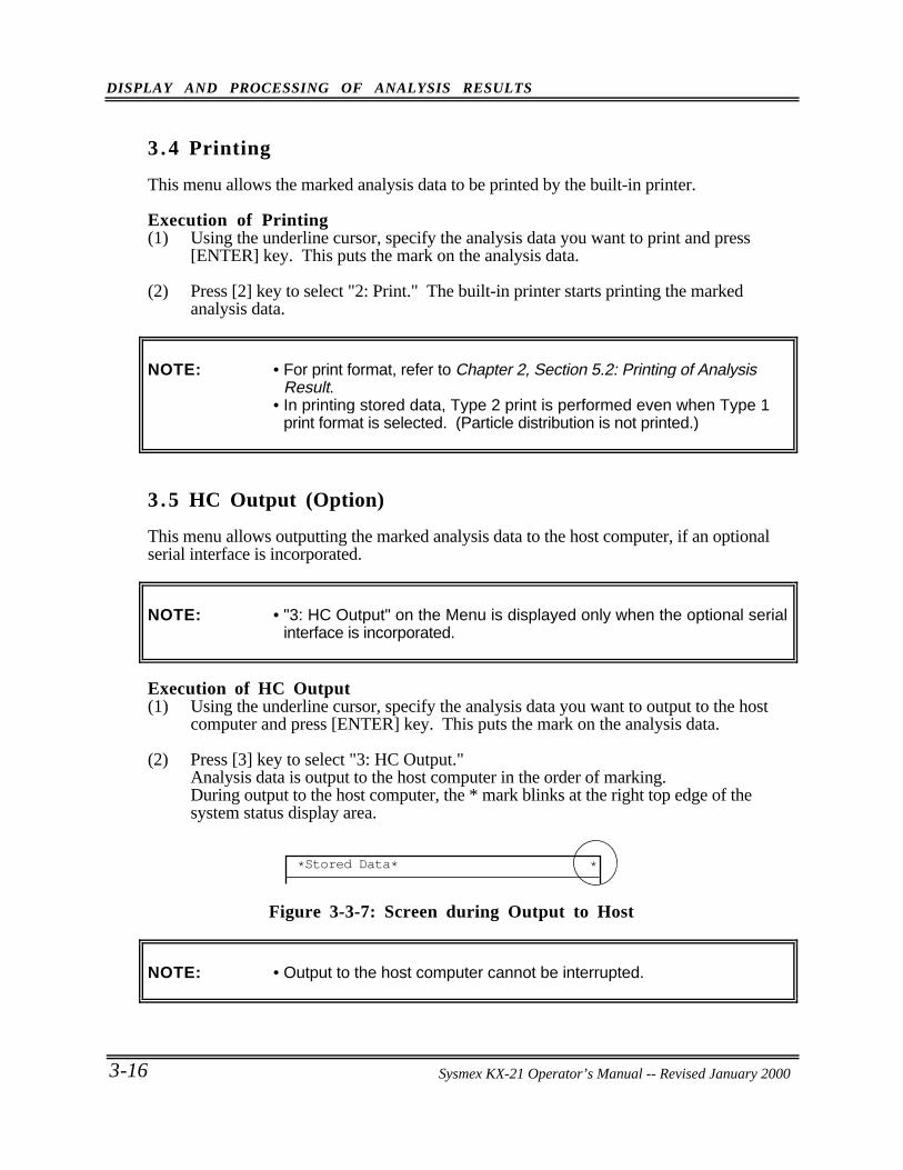
DISPLAY AND PROCESSING OF ANALYSIS RESULTS
3-16 Sysmex KX-21 Operator’s Manual -- Revised October 1998
3 .4 Printing
This menu allows the marked analysis data to be printed by the built-in printer.
Execution of Printing(1) Using the underline cursor, specify the analysis data you want to print and press
[ENTER] key. This puts the mark on the analysis data.
(2) Press [2] key to select "2: Print." The built-in printer starts printing the markedanalysis data.
NOTE: • For print format, refer to Chapter 2, Section 5.2: Printing of AnalysisResult.
• In printing stored data, Type 2 print is performed even when Type 1print format is selected. (Particle distribution is not printed.)
3 .5 HC Output (Option)
This menu allows outputting the marked analysis data to the host computer, if an optionalserial interface is incorporated.
NOTE: • "3: HC Output" on the Menu is displayed only when the optional serialinterface is incorporated.
Execution of HC Output(1) Using the underline cursor, specify the analysis data you want to output to the host
computer and press [ENTER] key. This puts the mark on the analysis data.
(2) Press [3] key to select "3: HC Output."Analysis data is output to the host computer in the order of marking.During output to the host computer, the * mark blinks at the right top edge of thesystem status display area.
*Stored Data* *
Figure 3-3-7: Screen during Output to Host
NOTE: • Output to the host computer cannot be interrupted.
Sysmex KX-21 Operator’s Manual -- Revised January 2000
DISPLAY AND PROCESSING OF ANALYSIS RESULTS
Sysmex KX-21 Operator’s Manual -- Revised October 1998 3-17
3 .6 Correcting a Sample Number
Use the [SAMPLE No.] key to correct a sample number of analysis data.
(1) Use the underline cursor to select the desired analysis data, then press the [SAMPLENo.] key. The selected sample number will be highlighted.
(2) Use the numeric keypad to enter a new sample number, then press the [ENTER] key.
(3) When the confirmation message appears, select the [Set] button.
Sysmex KX-21 Operator’s Manual -- Revised January 2000
CHAPTER 4 MAINTENANCE ANDSUPPLIES REPLACEMENT
1. INTRODUCTION ... . . . . . . . . . . . . . . . . . . . . . . . . . . . . . . . . . . . . . . . . . . . . . . . . . . . . . . . . . . . . . . 4-1
2. KX-21 MAINTENANCE CHECKLIST ... . . . . . . . . . . . . . . . . . . . . . . . . . . . . . . . . . . . . 4-2
3 DAILY MAINTENANCE AND PROCEDURE ... . . . . . . . . . . . . . . . . . . . . . . . . . . . . 4-43.1 Clean TD Chamber and Diluted Sample Line (Shutdown).. . . . . . . . . . . . 4-43.2 Check Trap Chamber Level and Discard .. . . . . . . . . . . . . . . . . . . . . . . . . . . . . . . . 4-6
4. WEEKLY MAINTENANCE AND PROCEDURE... . . . . . . . . . . . . . . . . . . . . . . . . . 4-74.1 Clean SRV Tray.. . . . . . . . . . . . . . . . . . . . . . . . . . . . . . . . . . . . . . . . . . . . . . . . . . . . . . . . . . . . 4-7
5. MONTHLY MAINTENANCE AND PROCEDURE ... . . . . . . . . . . . . . . . . . . . . . . 4-95.1 Clean Waste Chamber (Rinse Sequence).. . . . . . . . . . . . . . . . . . . . . . . . . . . . . . . . 4-95.2 Clean Transducer (Rinse Sequence) .. . . . . . . . . . . . . . . . . . . . . . . . . . . . . . . . . . . .4-12
6. EVERY 3-MONTH MAINTENANCE AND PROCEDURE ... . . . . . . . . . . . 4-166.1 Clean Sample Rotor Valve (SRV)... . . . . . . . . . . . . . . . . . . . . . . . . . . . . . . . . . . . . .4-166.2 Reset SRV Cycle Counter . . . . . . . . . . . . . . . . . . . . . . . . . . . . . . . . . . . . . . . . . . . . . . . .4-22
7. AS-NEEDED MAINTENANCE AND PROCEDURE... . . . . . . . . . . . . . . . . . . . 4-247.1 Auto Rinse .. . . . . . . . . . . . . . . . . . . . . . . . . . . . . . . . . . . . . . . . . . . . . . . . . . . . . . . . . . . . . . . . .4-247.2 Clean Rinse Cup ... . . . . . . . . . . . . . . . . . . . . . . . . . . . . . . . . . . . . . . . . . . . . . . . . . . . . . . . .4-267.3 Clean WBC/RBC Transducer Aperture .. . . . . . . . . . . . . . . . . . . . . . . . . . . . . . . .4-287.4 Replace Waste Tank ... . . . . . . . . . . . . . . . . . . . . . . . . . . . . . . . . . . . . . . . . . . . . . . . . . . . .4-32
8. SUPPLIES REPLACEMENT... . . . . . . . . . . . . . . . . . . . . . . . . . . . . . . . . . . . . . . . . . . . . . . . 4-338.1 Replenish Reagent .. . . . . . . . . . . . . . . . . . . . . . . . . . . . . . . . . . . . . . . . . . . . . . . . . . . . . . . .4-338.2 Replace Fuse.. . . . . . . . . . . . . . . . . . . . . . . . . . . . . . . . . . . . . . . . . . . . . . . . . . . . . . . . . . . . . . .4-368.3 Replace Printer Paper.. . . . . . . . . . . . . . . . . . . . . . . . . . . . . . . . . . . . . . . . . . . . . . . . . . . . .4-378.4 Supplies List. . . . . . . . . . . . . . . . . . . . . . . . . . . . . . . . . . . . . . . . . . . . . . . . . . . . . . . . . . . . . . . .4-40
9. CONFIRMATION OF CYCLE NUMBER... . . . . . . . . . . . . . . . . . . . . . . . . . . . . . . . . 4-419.1 Operation Procedure .. . . . . . . . . . . . . . . . . . . . . . . . . . . . . . . . . . . . . . . . . . . . . . . . . . . . . 4-41
MAINTENANCE AND SUPPLIES REPLACEMENT
Sysmex KX-21 Operator’s Manual -- Revised October 1998 4-1
1 . INTRODUCTION
To ensure that the instrument can function in its best state, it is necessary to give scheduledmaintenance. Perform maintenance according to the schedule below and record the result inthe Maintenance Checklist.
• Daily MaintenanceClean the TD chamber and diluted sample line. (Execute shutdown.)Check trap chamber level, and discard if necessary.
• Weekly MaintenanceClean the sample rotor valve (SRV) tray.
• Monthly Maintenance (or Every 2500 Samples)Clean the waste chamber (rinse sequence).Clean the transducer (rinse sequence).
• Every 3-Month Maintenance (or Every 7500 Samples)Clean the sample rotor valve (SRV).
• As-Needed MaintenanceAuto RinseClean the rinse cup.Clean WBC/RBC transducer aperture.Replace the waste tank.
This chapter describes supplies replacement together with these maintenance items.
• Supplies ReplacementReplenish reagent.Replace fuses.Replace printer paper.
Sysmex KX-21 Operator’s Manual -- Revised January 2000
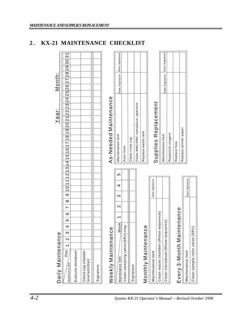
MAINTENANCE AND SUPPLIES REPLACEMENT
4-2 Sysmex KX-21 Operator’s Manual -- Revised October 1998
2 . KX-21 MAINTENANCE CHECKLIST
Sig
na
ture
12
34
56
78
91
01
11
21
31
41
51
61
71
81
92
02
12
22
32
42
52
62
72
82
93
03
1
Da
ily
Ma
inte
na
nc
e
Ex
ec
ute
sh
utd
ow
n
Ch
eck
tra
p c
ha
mb
er
leve
l an
d d
rain
Sig
na
ture
12
34
5C
lea
n s
am
pli
ng
va
lve
(SR
V)
tra
y
We
ek
ly M
ain
ten
an
ce
Mai
nten
ance
Ite
mD
ay
Mai
nten
ance
Ite
m
We
ek
Dat
e, S
igna
ture
Ma
inte
na
nc
e it
em
Cle
an
wa
ste
ch
am
be
r (R
ins
e s
eq
ue
nc
e)
Cle
an
tra
ns
du
ce
r (R
ins
e s
eq
ue
nc
e)
Mo
nth
ly M
ain
ten
an
ce
Da
te, S
ign
atu
reM
ain
ten
an
ce
ite
m
Re
pla
ce
pri
nte
r p
ap
er
Da
te, S
ign
atu
re
Re
ple
nis
h r
ea
ge
nt
Re
pla
ce
fu
se
Su
pp
lie
s R
ep
lac
em
en
t
Cle
an
sa
mp
le r
oto
r v
alv
e (
SR
V)
Ma
inte
na
nc
e i
tem
D
ate,
Sig
natu
re
Ev
ery
3-M
on
th M
ain
ten
an
ce
Da
te, S
ign
atu
reM
ain
ten
an
ce
ite
m
Da
te, S
ign
atu
re
Cle
an
WB
C/R
BC
tra
ns
du
ce
r a
pe
rtu
re
Re
pla
ce
wa
ste
ta
nk
Cle
an
rin
se
cu
p
Au
to r
ins
e
As
-Ne
ed
ed
Ma
inte
na
nc
e
Ye
ar:
M
on
th:
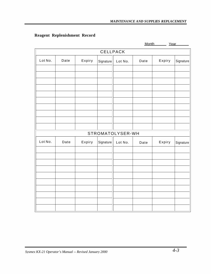
MAINTENANCE AND SUPPLIES REPLACEMENT
Sysmex KX-21 Operator’s Manual -- Revised October 1998 4-3
Reagent Replenishment Record
CELLPACK
STROMATOLYSER-WH
Lot No. DateExpiry Signature Expiry
Date Expiry Expiry
Date
DateLot No. Lot No.
Lot No.
Signature
Signature
Signature
YearMonth
Sysmex KX-21 Operator’s Manual -- Revised January 2000
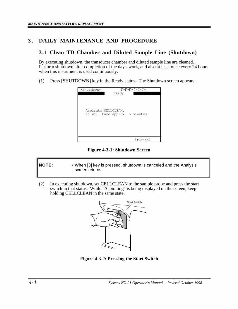
MAINTENANCE AND SUPPLIES REPLACEMENT
4-4 Sysmex KX-21 Operator’s Manual -- Revised October 1998
3 . DAILY MAINTENANCE AND PROCEDURE
3.1 Clean TD Chamber and Diluted Sample Line (Shutdown)
By executing shutdown, the transducer chamber and diluted sample line are cleaned.Perform shutdown after completion of the day's work, and also at least once every 24 hourswhen this instrument is used continuously.
(1) Press [SHUTDOWN] key in the Ready status. The Shutdown screen appears.
3:Cancel
*Shutdown*
Aspirate CELLCLEAN.It will take approx. 5 minutes.
Ready
Figure 4-3-1: Shutdown Screen
NOTE: • When [3] key is pressed, shutdown is canceled and the Analysisscreen returns.
(2) In executing shutdown, set CELLCLEAN to the sample probe and press the startswitch in that status. While "Aspirating" is being displayed on the screen, keepholding CELLCLEAN in the same state.
Start Switch
Figure 4-3-2: Pressing the Start Switch
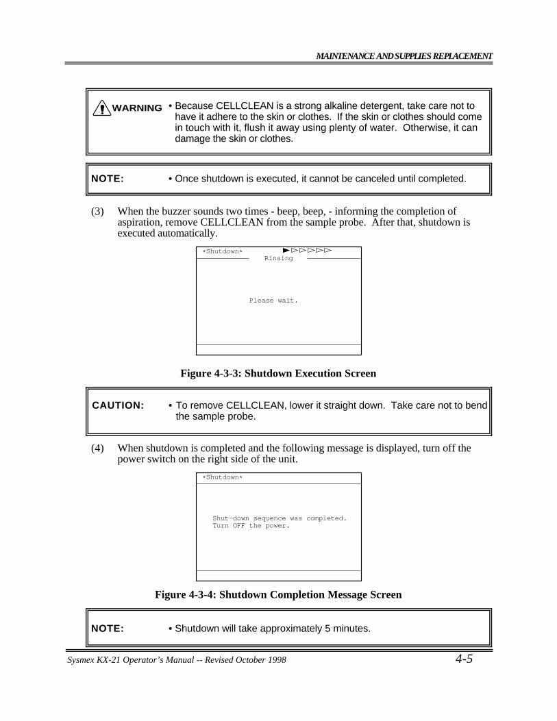
MAINTENANCE AND SUPPLIES REPLACEMENT
Sysmex KX-21 Operator’s Manual -- Revised October 1998 4-5
• Because CELLCLEAN is a strong alkaline detergent, take care not tohave it adhere to the skin or clothes. If the skin or clothes should comein touch with it, flush it away using plenty of water. Otherwise, it candamage the skin or clothes.
NOTE: • Once shutdown is executed, it cannot be canceled until completed.
(3) When the buzzer sounds two times - beep, beep, - informing the completion ofaspiration, remove CELLCLEAN from the sample probe. After that, shutdown isexecuted automatically.
Rinsing*Shutdown*
Please wait.
Figure 4-3-3: Shutdown Execution Screen
CAUTION: • To remove CELLCLEAN, lower it straight down. Take care not to bendthe sample probe.
(4) When shutdown is completed and the following message is displayed, turn off thepower switch on the right side of the unit.
Shut-down sequence was completed.Turn OFF the power.
*Shutdown*
Figure 4-3-4: Shutdown Completion Message Screen
NOTE: • Shutdown will take approximately 5 minutes.
WARNING
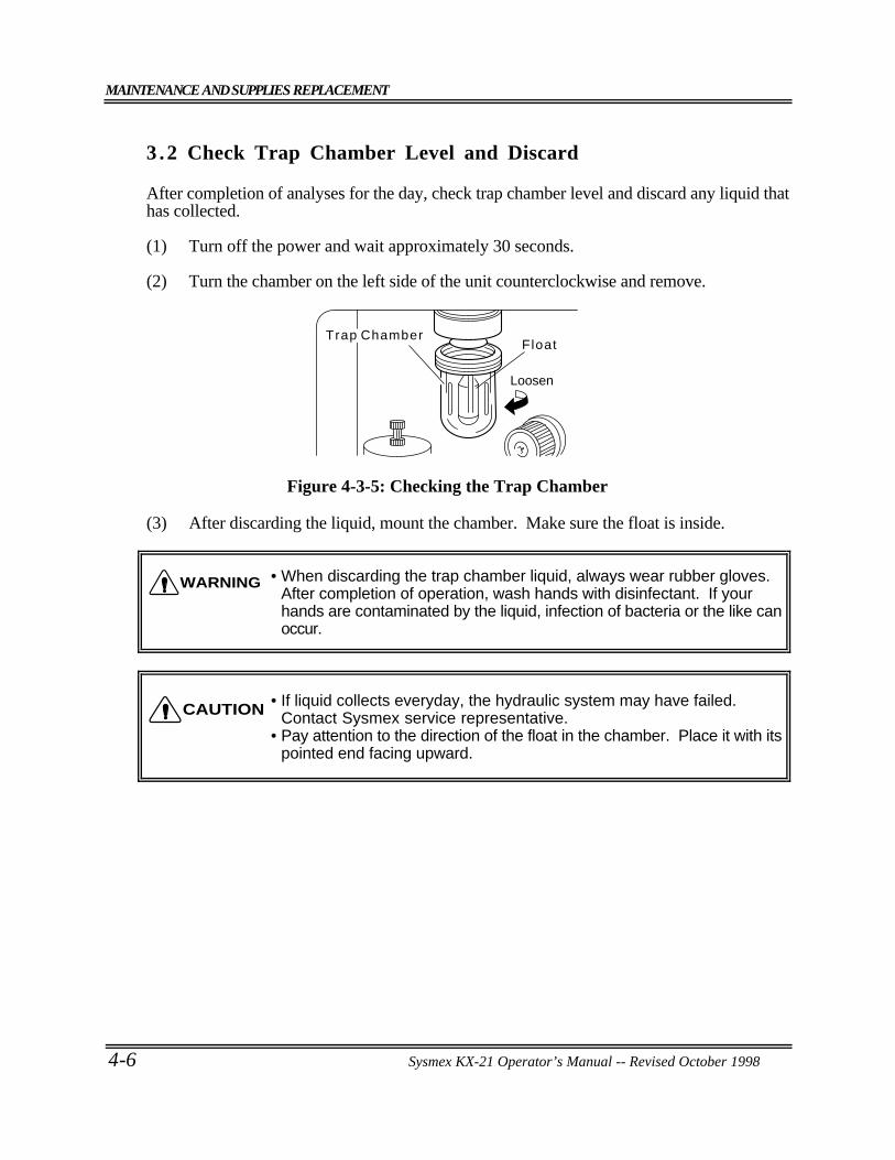
MAINTENANCE AND SUPPLIES REPLACEMENT
4-6 Sysmex KX-21 Operator’s Manual -- Revised October 1998
3 .2 Check Trap Chamber Level and Discard
After completion of analyses for the day, check trap chamber level and discard any liquid thathas collected.
(1) Turn off the power and wait approximately 30 seconds.
(2) Turn the chamber on the left side of the unit counterclockwise and remove.
Trap Chamber
Loosen
Float
Figure 4-3-5: Checking the Trap Chamber
(3) After discarding the liquid, mount the chamber. Make sure the float is inside.
• When discarding the trap chamber liquid, always wear rubber gloves.After completion of operation, wash hands with disinfectant. If yourhands are contaminated by the liquid, infection of bacteria or the like canoccur.
• If liquid collects everyday, the hydraulic system may have failed.Contact Sysmex service representative.
• Pay attention to the direction of the float in the chamber. Place it with itspointed end facing upward.
WARNING
CAUTION
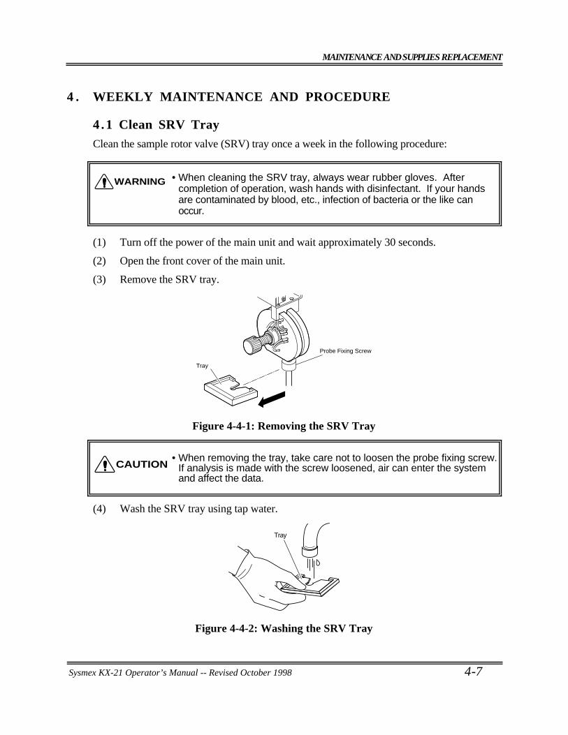
MAINTENANCE AND SUPPLIES REPLACEMENT
Sysmex KX-21 Operator’s Manual -- Revised October 1998 4-7
4 . WEEKLY MAINTENANCE AND PROCEDURE
4.1 Clean SRV TrayClean the sample rotor valve (SRV) tray once a week in the following procedure:
• When cleaning the SRV tray, always wear rubber gloves. Aftercompletion of operation, wash hands with disinfectant. If your handsare contaminated by blood, etc., infection of bacteria or the like canoccur.
(1) Turn off the power of the main unit and wait approximately 30 seconds.
(2) Open the front cover of the main unit.
(3) Remove the SRV tray.
Tray
Probe Fixing Screw
Figure 4-4-1: Removing the SRV Tray
• When removing the tray, take care not to loosen the probe fixing screw.If analysis is made with the screw loosened, air can enter the systemand affect the data.
(4) Wash the SRV tray using tap water.
Tray
Figure 4-4-2: Washing the SRV Tray
WARNING
CAUTION
MAINTENANCE AND SUPPLIES REPLACEMENT
4-8 Sysmex KX-21 Operator’s Manual -- Revised October 1998
(5) Make sure no contaminants remain, then wipe off water.
(6) Re-mount the SRV tray to the original state.
• After mounting the tray, make sure the probe fixing screw is not loose.If analysis is made with the screw loosened, air can enter the systemand affect the data.
CAUTION: • Mount the SRV tray properly as to the face/bottom and the direction.
(7) Close the front cover of the main unit.
CAUTION
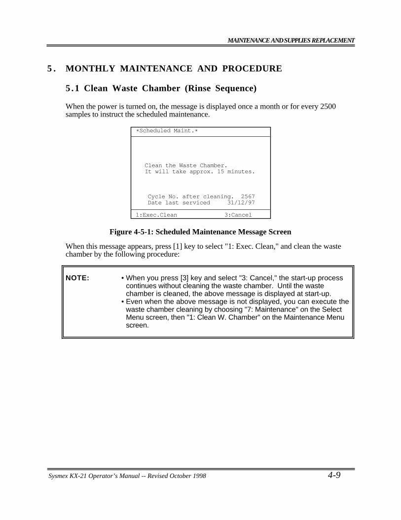
MAINTENANCE AND SUPPLIES REPLACEMENT
Sysmex KX-21 Operator’s Manual -- Revised October 1998 4-9
5 . MONTHLY MAINTENANCE AND PROCEDURE
5.1 Clean Waste Chamber (Rinse Sequence)
When the power is turned on, the message is displayed once a month or for every 2500samples to instruct the scheduled maintenance.
*Scheduled Maint.*
1:Exec.Clean 3:Cancel
Clean the Waste Chamber.It will take approx. 15 minutes.
Cycle No. after cleaning. 2567Date last serviced 31/12/97
Figure 4-5-1: Scheduled Maintenance Message Screen
When this message appears, press [1] key to select "1: Exec. Clean," and clean the wastechamber by the following procedure:
NOTE: • When you press [3] key and select "3: Cancel," the start-up processcontinues without cleaning the waste chamber. Until the wastechamber is cleaned, the above message is displayed at start-up.
• Even when the above message is not displayed, you can execute thewaste chamber cleaning by choosing "7: Maintenance" on the SelectMenu screen, then "1: Clean W. Chamber" on the Maintenance Menuscreen.
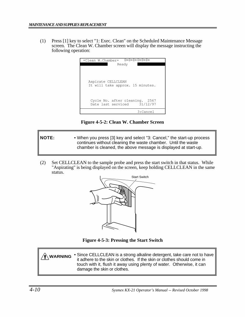
MAINTENANCE AND SUPPLIES REPLACEMENT
4-10 Sysmex KX-21 Operator’s Manual -- Revised October 1998
(1) Press [1] key to select "1: Exec. Clean" on the Scheduled Maintenance Messagescreen. The Clean W. Chamber screen will display the message instructing thefollowing operation:
*Clean W.Chamber*
Cycle No. after cleaning. 2567Date last serviced 31/12/97
3:Cancel
Ready
Aspirate CELLCLEANIt will take approx. 15 minutes.
Figure 4-5-2: Clean W. Chamber Screen
NOTE: • When you press [3] key and select "3: Cancel," the start-up processcontinues without cleaning the waste chamber. Until the wastechamber is cleaned, the above message is displayed at start-up.
(2) Set CELLCLEAN to the sample probe and press the start switch in that status. While"Aspirating" is being displayed on the screen, keep holding CELLCLEAN in the samestatus.
Start Switch
Figure 4-5-3: Pressing the Start Switch
• Since CELLCLEAN is a strong alkaline detergent, take care not to haveit adhere to the skin or clothes. If the skin or clothes should come intouch with it, flush it away using plenty of water. Otherwise, it candamage the skin or clothes.
WARNING
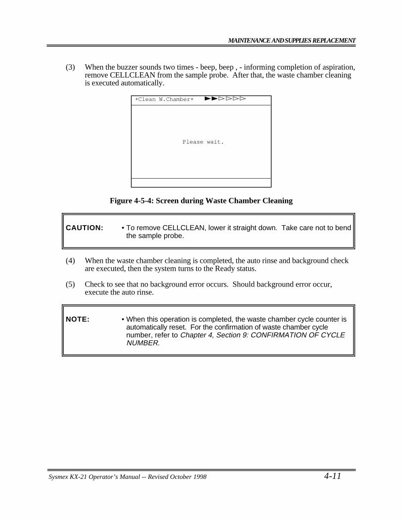
MAINTENANCE AND SUPPLIES REPLACEMENT
Sysmex KX-21 Operator’s Manual -- Revised October 1998 4-11
(3) When the buzzer sounds two times - beep, beep , - informing completion of aspiration,remove CELLCLEAN from the sample probe. After that, the waste chamber cleaningis executed automatically.
*Clean W.Chamber*
Please wait.
Figure 4-5-4: Screen during Waste Chamber Cleaning
CAUTION: • To remove CELLCLEAN, lower it straight down. Take care not to bendthe sample probe.
(4) When the waste chamber cleaning is completed, the auto rinse and background checkare executed, then the system turns to the Ready status.
(5) Check to see that no background error occurs. Should background error occur,execute the auto rinse.
NOTE: • When this operation is completed, the waste chamber cycle counter isautomatically reset. For the confirmation of waste chamber cyclenumber, refer to Chapter 4, Section 9: CONFIRMATION OF CYCLENUMBER.
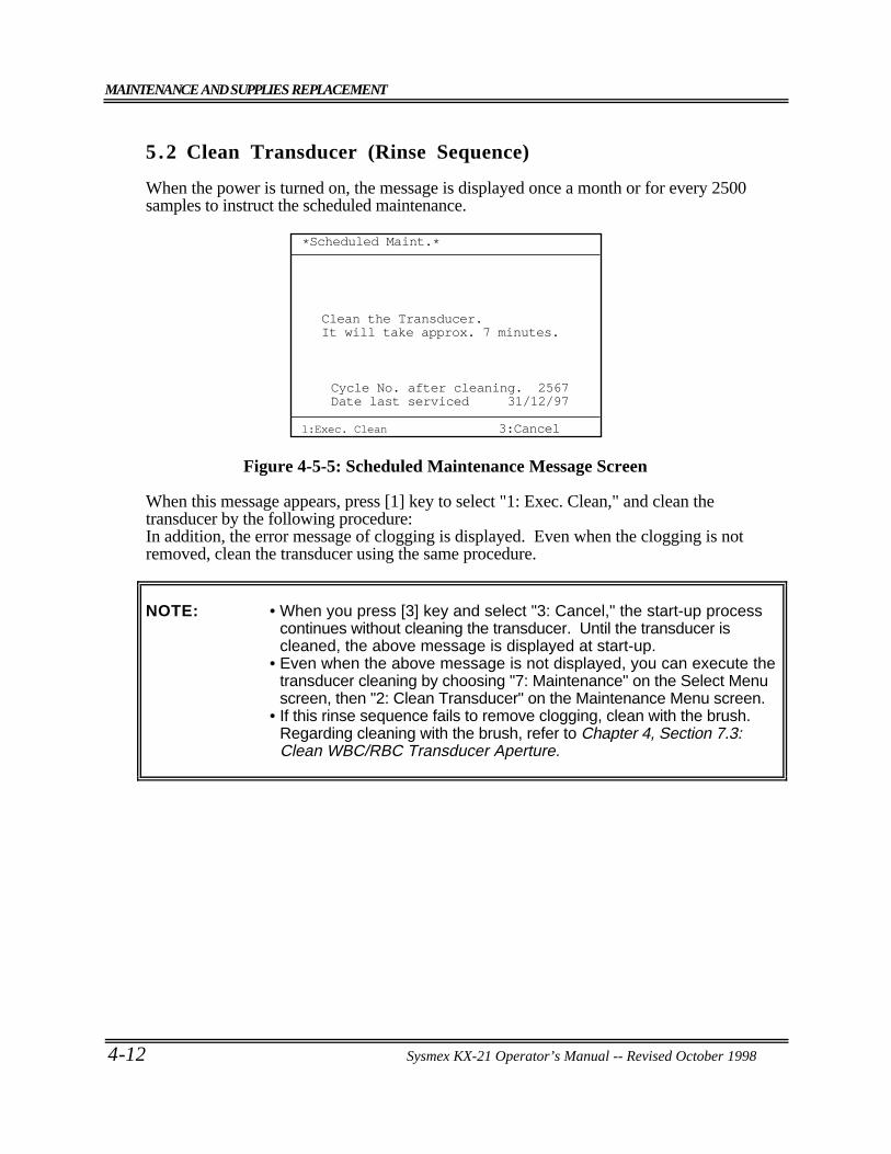
MAINTENANCE AND SUPPLIES REPLACEMENT
4-12 Sysmex KX-21 Operator’s Manual -- Revised October 1998
5 .2 Clean Transducer (Rinse Sequence)
When the power is turned on, the message is displayed once a month or for every 2500samples to instruct the scheduled maintenance.
1:Exec. Clean
Clean the Transducer.It will take approx. 7 minutes.
*Scheduled Maint.*
Cycle No. after cleaning. 2567Date last serviced 31/12/97
3:Cancel
Figure 4-5-5: Scheduled Maintenance Message Screen
When this message appears, press [1] key to select "1: Exec. Clean," and clean thetransducer by the following procedure:In addition, the error message of clogging is displayed. Even when the clogging is notremoved, clean the transducer using the same procedure.
NOTE: • When you press [3] key and select "3: Cancel," the start-up processcontinues without cleaning the transducer. Until the transducer iscleaned, the above message is displayed at start-up.
• Even when the above message is not displayed, you can execute thetransducer cleaning by choosing "7: Maintenance" on the Select Menuscreen, then "2: Clean Transducer" on the Maintenance Menu screen.
• If this rinse sequence fails to remove clogging, clean with the brush.Regarding cleaning with the brush, refer to Chapter 4, Section 7.3:Clean WBC/RBC Transducer Aperture.
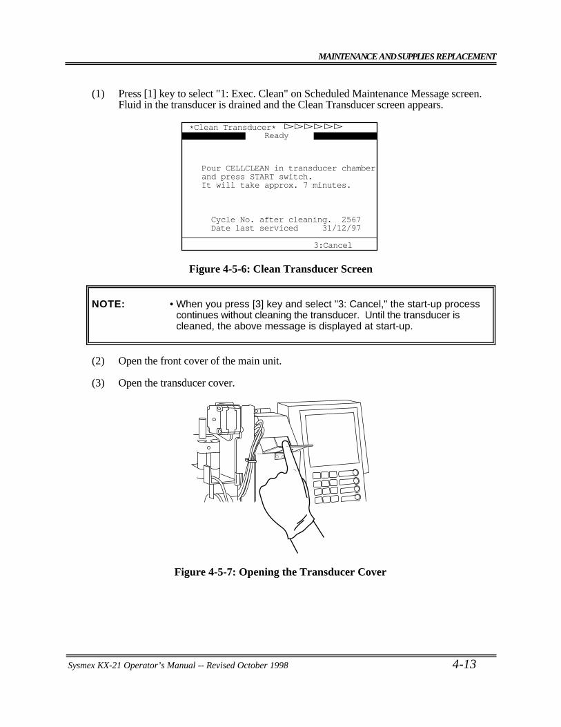
MAINTENANCE AND SUPPLIES REPLACEMENT
Sysmex KX-21 Operator’s Manual -- Revised October 1998 4-13
(1) Press [1] key to select "1: Exec. Clean" on Scheduled Maintenance Message screen.Fluid in the transducer is drained and the Clean Transducer screen appears.
*Clean Transducer*
Pour CELLCLEAN in transducer chamberand press START switch.It will take approx. 7 minutes.
Cycle No. after cleaning. 2567Date last serviced 31/12/97
3:Cancel
Ready
Figure 4-5-6: Clean Transducer Screen
NOTE: • When you press [3] key and select "3: Cancel," the start-up processcontinues without cleaning the transducer. Until the transducer iscleaned, the above message is displayed at start-up.
(2) Open the front cover of the main unit.
(3) Open the transducer cover.
Figure 4-5-7: Opening the Transducer Cover
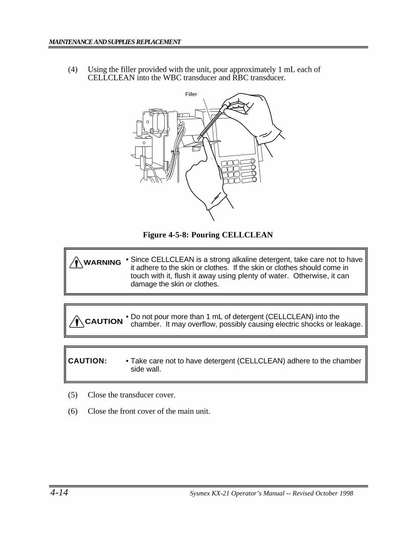
MAINTENANCE AND SUPPLIES REPLACEMENT
4-14 Sysmex KX-21 Operator’s Manual -- Revised October 1998
(4) Using the filler provided with the unit, pour approximately 1 mL each ofCELLCLEAN into the WBC transducer and RBC transducer.
Filler
Figure 4-5-8: Pouring CELLCLEAN
• Since CELLCLEAN is a strong alkaline detergent, take care not to haveit adhere to the skin or clothes. If the skin or clothes should come intouch with it, flush it away using plenty of water. Otherwise, it candamage the skin or clothes.
• Do not pour more than 1 mL of detergent (CELLCLEAN) into thechamber. It may overflow, possibly causing electric shocks or leakage.
CAUTION: • Take care not to have detergent (CELLCLEAN) adhere to the chamberside wall.
(5) Close the transducer cover.
(6) Close the front cover of the main unit.
WARNING
CAUTION
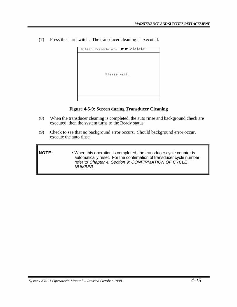
MAINTENANCE AND SUPPLIES REPLACEMENT
Sysmex KX-21 Operator’s Manual -- Revised October 1998 4-15
(7) Press the start switch. The transducer cleaning is executed.
*Clean Transducer*
Please wait.
Figure 4-5-9: Screen during Transducer Cleaning
(8) When the transducer cleaning is completed, the auto rinse and background check areexecuted, then the system turns to the Ready status.
(9) Check to see that no background error occurs. Should background error occur,execute the auto rinse.
NOTE: • When this operation is completed, the transducer cycle counter isautomatically reset. For the confirmation of transducer cycle number,refer to Chapter 4, Section 9: CONFIRMATION OF CYCLENUMBER.
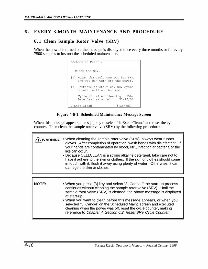
MAINTENANCE AND SUPPLIES REPLACEMENT
4-16 Sysmex KX-21 Operator’s Manual -- Revised October 1998
6 . EVERY 3-MONTH MAINTENANCE AND PROCEDURE
6.1 Clean Sample Rotor Valve (SRV)
When the power is turned on, the message is displayed once every three months or for every7500 samples to instruct the scheduled maintenance.
*Scheduled Maint.*
1:Exec.Clean
Clean the SRV.
Cycle No. after cleaning. 7567Date last serviced 31/12/97
Reset the cycle counter for SRV, and you can turn OFF the power.[1]
[3] Continue to start up. SRV cycle counter will not be reset.
3:Cancel
Figure 4-6-1: Scheduled Maintenance Message Screen
When this message appears, press [1] key to select "1: Exec. Clean," and reset the cyclecounter. Then clean the sample rotor valve (SRV) by the following procedure:
• When cleaning the sample rotor valve (SRV), always wear rubbergloves. After completion of operation, wash hands with disinfectant. Ifyour hands are contaminated by blood, etc., infection of bacteria or thelike can occur.
• Because CELLCLEAN is a strong alkaline detergent, take care not tohave it adhere to the skin or clothes. If the skin or clothes should comein touch with it, flush it away using plenty of water. Otherwise, it candamage the skin or clothes.
NOTE: • When you press [3] key and select "3: Cancel," the start-up processcontinues without cleaning the sample rotor valve (SRV). Until thesample rotor valve (SRV) is cleaned, the above message is displayedat start-up.
• When you want to clean before this message appears, or when youselected "3: Cancel" on the Scheduled Maint. screen and executedcleaning when the power was off, reset the cycle counter, makingreference to Chapter 4, Section 6.2: Reset SRV Cycle Counter.
WARNING
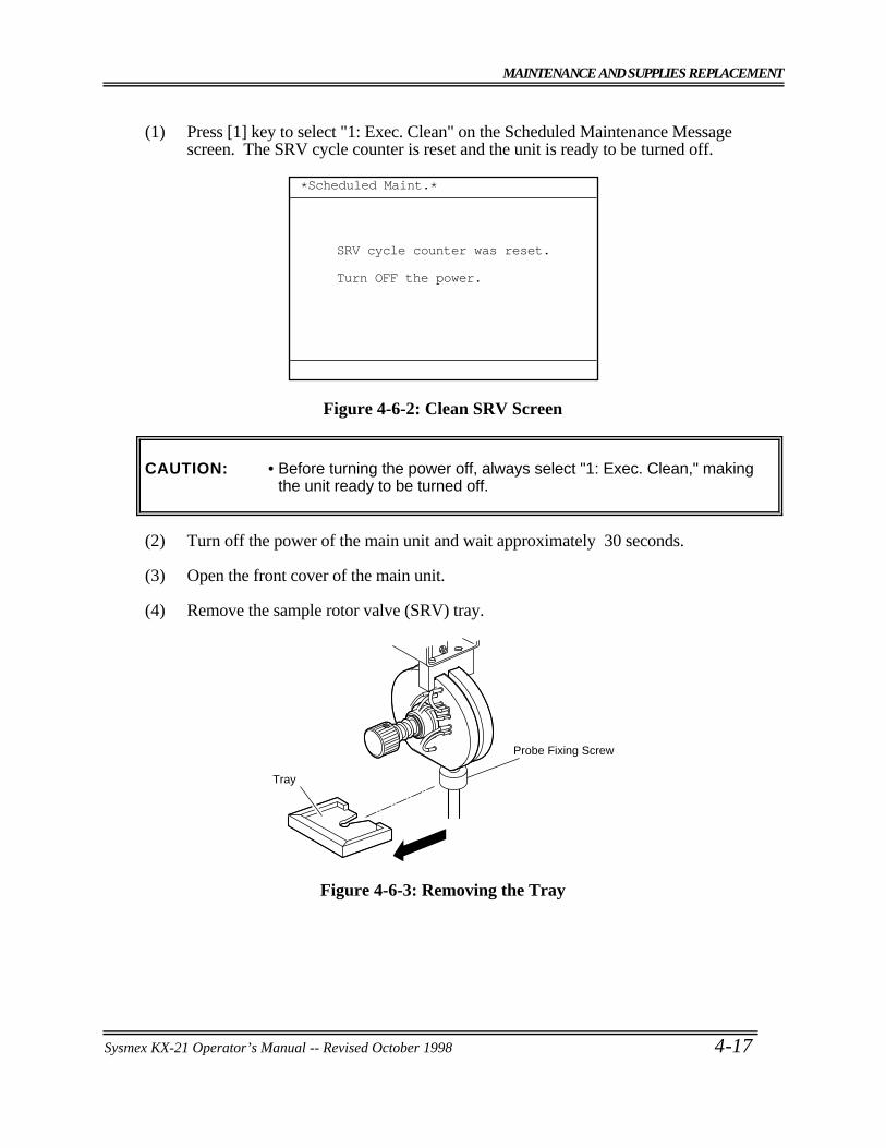
MAINTENANCE AND SUPPLIES REPLACEMENT
Sysmex KX-21 Operator’s Manual -- Revised October 1998 4-17
(1) Press [1] key to select "1: Exec. Clean" on the Scheduled Maintenance Messagescreen. The SRV cycle counter is reset and the unit is ready to be turned off.
*Scheduled Maint.*
SRV cycle counter was reset.
Turn OFF the power.
Figure 4-6-2: Clean SRV Screen
CAUTION: • Before turning the power off, always select "1: Exec. Clean," makingthe unit ready to be turned off.
(2) Turn off the power of the main unit and wait approximately 30 seconds.
(3) Open the front cover of the main unit.
(4) Remove the sample rotor valve (SRV) tray.
Tray
Probe Fixing Screw
Figure 4-6-3: Removing the Tray
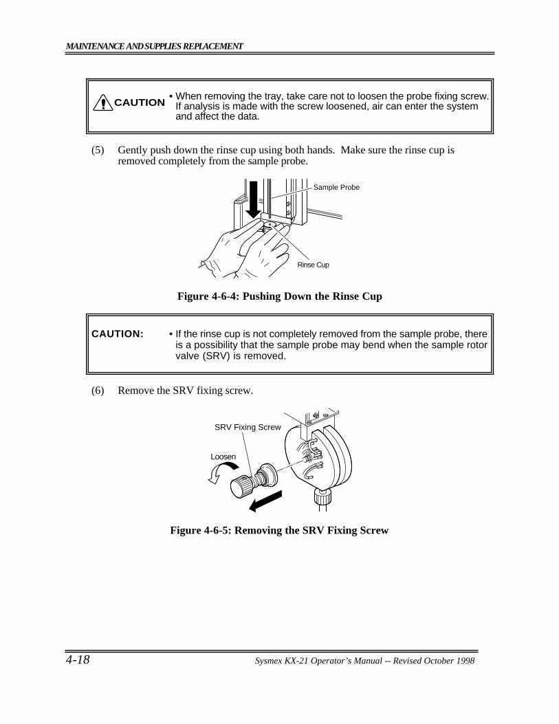
MAINTENANCE AND SUPPLIES REPLACEMENT
4-18 Sysmex KX-21 Operator’s Manual -- Revised October 1998
• When removing the tray, take care not to loosen the probe fixing screw.If analysis is made with the screw loosened, air can enter the systemand affect the data.
(5) Gently push down the rinse cup using both hands. Make sure the rinse cup isremoved completely from the sample probe.
Sample Probe
Rinse Cup
Figure 4-6-4: Pushing Down the Rinse Cup
CAUTION: • If the rinse cup is not completely removed from the sample probe, thereis a possibility that the sample probe may bend when the sample rotorvalve (SRV) is removed.
(6) Remove the SRV fixing screw.
SRV Fixing Screw
Loosen
Figure 4-6-5: Removing the SRV Fixing Screw
CAUTION
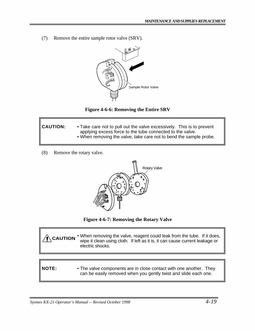
MAINTENANCE AND SUPPLIES REPLACEMENT
Sysmex KX-21 Operator’s Manual -- Revised October 1998 4-19
(7) Remove the entire sample rotor valve (SRV).
Sample Rotor Valve
Figure 4-6-6: Removing the Entire SRV
CAUTION: • Take care not to pull out the valve excessively. This is to preventapplying excess force to the tube connected to the valve.
• When removing the valve, take care not to bend the sample probe.
(8) Remove the rotary valve.
Rotary Valve
Figure 4-6-7: Removing the Rotary Valve
• When removing the valve, reagent could leak from the tube. If it does,wipe it clean using cloth. If left as it is, it can cause current leakage orelectric shocks.
NOTE: • The valve components are in close contact with one another. Theycan be easily removed when you gently twist and slide each one.
CAUTION
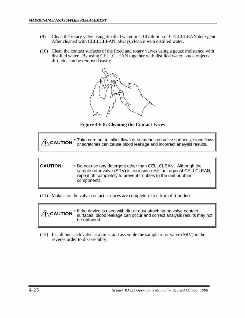
MAINTENANCE AND SUPPLIES REPLACEMENT
4-20 Sysmex KX-21 Operator’s Manual -- Revised October 1998
(9) Clean the rotary valve using distilled water or 1:10 dilution of CELLCLEAN detergent.After cleaned with CELLCLEAN, always clean it with distilled water.
(10) Clean the contact surfaces of the fixed and rotary valves using a gauze moistened withdistilled water. By using CELLCLEAN together with distilled water, stuck objects,dirt, etc. can be removed easily.
Figure 4-6-8: Cleaning the Contact Faces
• Take care not to inflict flaws or scratches on valve surfaces, since flawsor scratches can cause blood leakage and incorrect analysis results.
CAUTION: • Do not use any detergent other than CELLCLEAN. Although thesample rotor valve (SRV) is corrosion-resistant against CELLCLEAN,wipe it off completely to prevent troubles to the unit or othercomponents.
(11) Make sure the valve contact surfaces are completely free from dirt or dust.
• If the device is used with dirt or dust attaching on valve contactsurfaces, blood leakage can occur and correct analysis results may notbe obtained.
(12) Install one each valve at a time, and assemble the sample rotor valve (SRV) in thereverse order to disassembly.
CAUTION
CAUTION
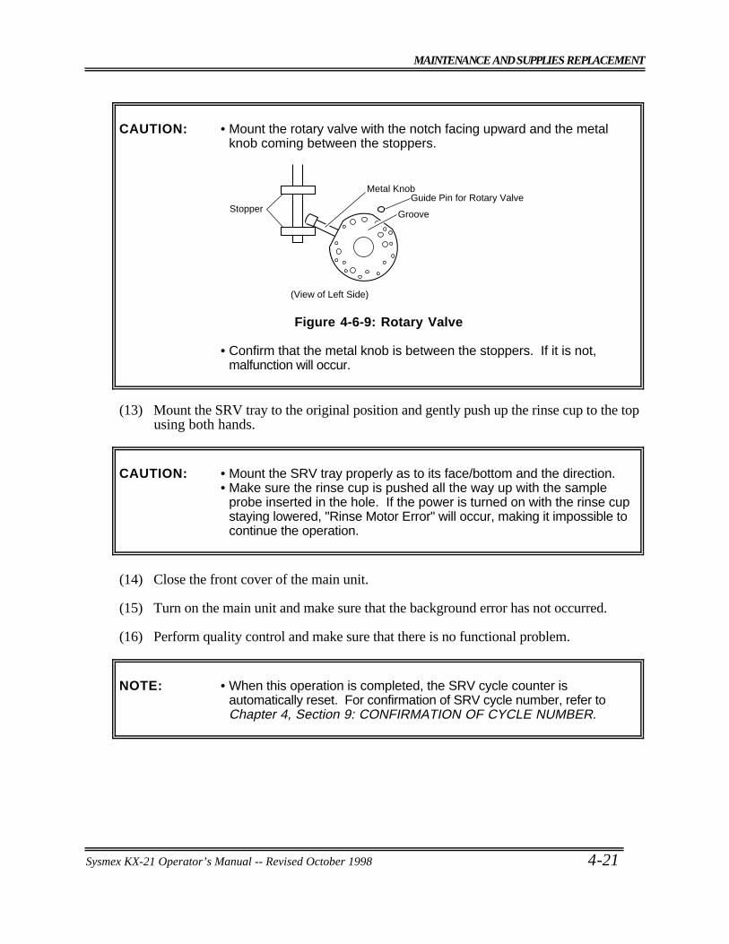
MAINTENANCE AND SUPPLIES REPLACEMENT
Sysmex KX-21 Operator’s Manual -- Revised October 1998 4-21
CAUTION: • Mount the rotary valve with the notch facing upward and the metalknob coming between the stoppers.
Stopper
Metal Knob
Groove
Guide Pin for Rotary Valve
(View of Left Side)
Figure 4-6-9: Rotary Valve
• Confirm that the metal knob is between the stoppers. If it is not,malfunction will occur.
(13) Mount the SRV tray to the original position and gently push up the rinse cup to the topusing both hands.
CAUTION: • Mount the SRV tray properly as to its face/bottom and the direction.• Make sure the rinse cup is pushed all the way up with the sample
probe inserted in the hole. If the power is turned on with the rinse cupstaying lowered, "Rinse Motor Error" will occur, making it impossible tocontinue the operation.
(14) Close the front cover of the main unit.
(15) Turn on the main unit and make sure that the background error has not occurred.
(16) Perform quality control and make sure that there is no functional problem.
NOTE: • When this operation is completed, the SRV cycle counter isautomatically reset. For confirmation of SRV cycle number, refer toChapter 4, Section 9: CONFIRMATION OF CYCLE NUMBER.
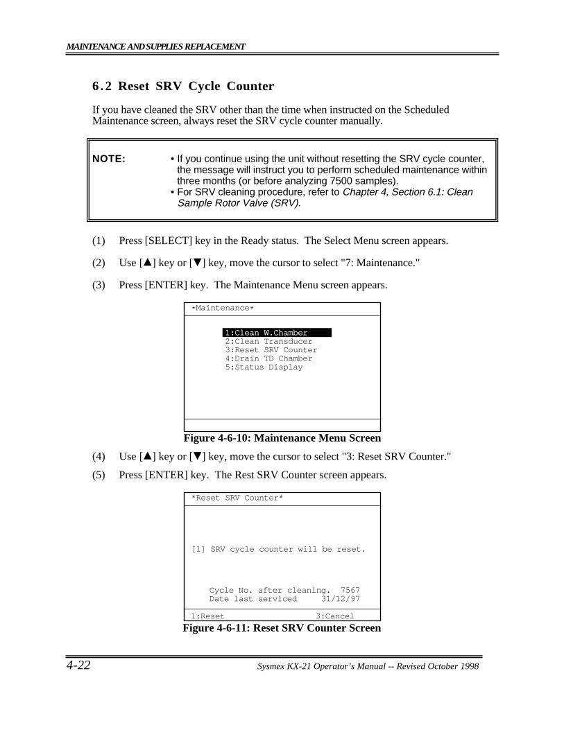
MAINTENANCE AND SUPPLIES REPLACEMENT
4-22 Sysmex KX-21 Operator’s Manual -- Revised October 1998
6 .2 Reset SRV Cycle Counter
If you have cleaned the SRV other than the time when instructed on the ScheduledMaintenance screen, always reset the SRV cycle counter manually.
NOTE: • If you continue using the unit without resetting the SRV cycle counter,the message will instruct you to perform scheduled maintenance withinthree months (or before analyzing 7500 samples).
• For SRV cleaning procedure, refer to Chapter 4, Section 6.1: CleanSample Rotor Valve (SRV).
(1) Press [SELECT] key in the Ready status. The Select Menu screen appears.
(2) Use [ ] key or [ ] key, move the cursor to select "7: Maintenance."
(3) Press [ENTER] key. The Maintenance Menu screen appears.
*Maintenance*
1:Clean W.Chamber2:Clean Transducer3:Reset SRV Counter4:Drain TD Chamber5:Status Display
Figure 4-6-10: Maintenance Menu Screen
(4) Use [ ] key or [ ] key, move the cursor to select "3: Reset SRV Counter."
(5) Press [ENTER] key. The Rest SRV Counter screen appears.
*Reset SRV Counter*
3:Cancel1:Reset
1 SRV cycle counter will be reset.[ ]
Cycle No. after cleaning. 7567Date last serviced 31/12/97
Figure 4-6-11: Reset SRV Counter Screen
MAINTENANCE AND SUPPLIES REPLACEMENT
Sysmex KX-21 Operator’s Manual -- Revised October 1998 4-23
(6) Press [1] key to select "1: Reset." "Cycle No. after cleaning" is reset to "0," the dateof the present day is entered in the "Date last serviced" column, then the Analysisscreen returns.
NOTE: • Press [3] key to select "3: Cancel." The cycle counter is not reset, andthe Analysis screen returns.
• For confirmation of SRV cycle counter, refer to Chapter 4, Section 9:CONFIRMATION OF CYCLE NUMBER.
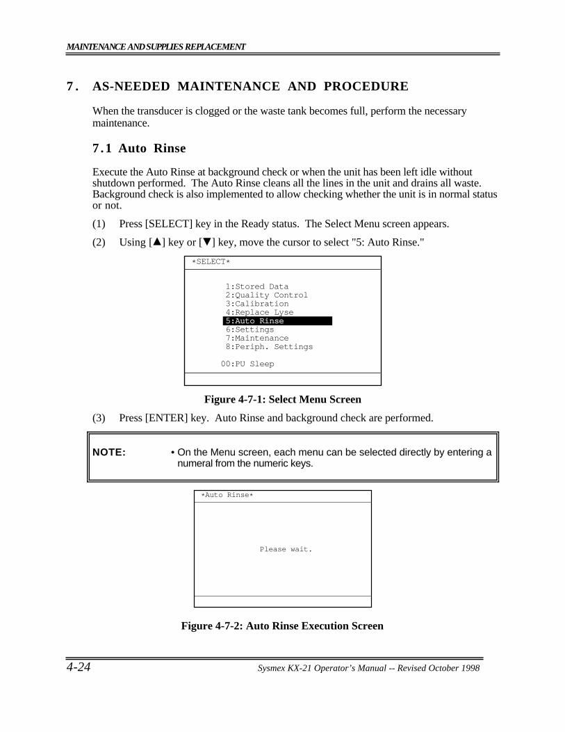
MAINTENANCE AND SUPPLIES REPLACEMENT
4-24 Sysmex KX-21 Operator’s Manual -- Revised October 1998
7 . AS-NEEDED MAINTENANCE AND PROCEDURE
When the transducer is clogged or the waste tank becomes full, perform the necessarymaintenance.
7 .1 Auto Rinse
Execute the Auto Rinse at background check or when the unit has been left idle withoutshutdown performed. The Auto Rinse cleans all the lines in the unit and drains all waste.Background check is also implemented to allow checking whether the unit is in normal statusor not.
(1) Press [SELECT] key in the Ready status. The Select Menu screen appears.
(2) Using [ ] key or [ ] key, move the cursor to select "5: Auto Rinse."
*SELECT*
1:Stored Data2:Quality Control3:Calibration4:Replace Lyse5:Auto Rinse6:Settings7:Maintenance8:Periph. Settings
00:PU Sleep
Figure 4-7-1: Select Menu Screen
(3) Press [ENTER] key. Auto Rinse and background check are performed.
NOTE: • On the Menu screen, each menu can be selected directly by entering anumeral from the numeric keys.
*Auto Rinse*
Please wait.
Figure 4-7-2: Auto Rinse Execution Screen
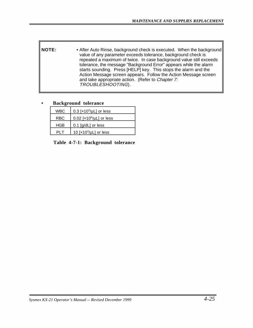
MAINTENANCE AND SUPPLIES REPLACEMENT
Sysmex KX-21 Operator’s Manual -- Revised October 1998 4-25
NOTE: • After Auto Rinse, background check is executed. When the backgroundvalue of any parameter exceeds tolerance, background check isrepeated a maximum of twice. In case background value still exceedstolerance, the message "Background Error" appears while the alarmstarts sounding. Press [HELP] key. This stops the alarm and theAction Message screen appears. Follow the Action Message screenand take appropriate action. (Refer to Chapter 7:TROUBLESHOOTING).
• Background tolerance
WBC 0.3 [×103/µL] or less
RBC 0.02 [×106/µL] or less
HGB 0.1 [g/dL] or less
PLT 10 [×103/µL] or less
Table 4-7-1: Background tolerance
Sysmex KX-21 Operator’s Manual -- Revised December 1999
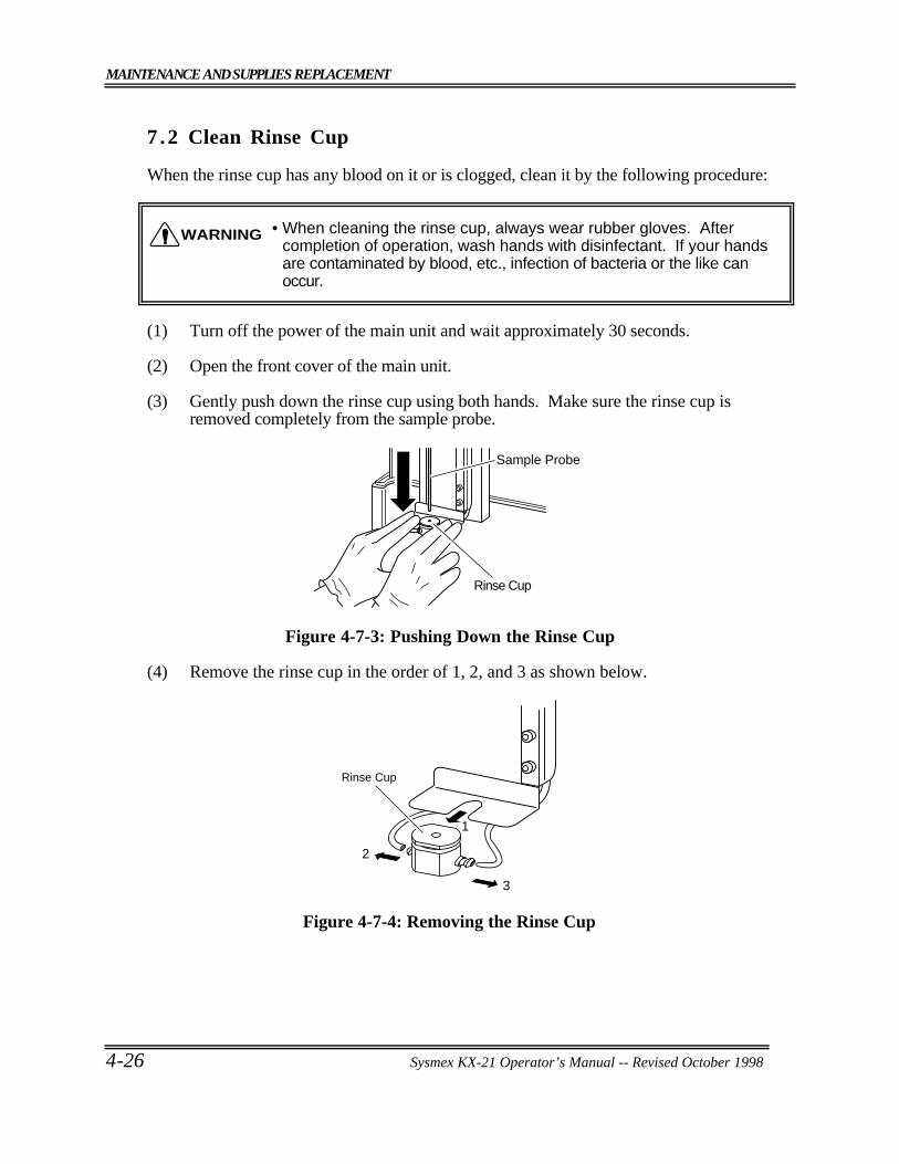
MAINTENANCE AND SUPPLIES REPLACEMENT
4-26 Sysmex KX-21 Operator’s Manual -- Revised October 1998
7 .2 Clean Rinse Cup
When the rinse cup has any blood on it or is clogged, clean it by the following procedure:
• When cleaning the rinse cup, always wear rubber gloves. Aftercompletion of operation, wash hands with disinfectant. If your handsare contaminated by blood, etc., infection of bacteria or the like canoccur.
(1) Turn off the power of the main unit and wait approximately 30 seconds.
(2) Open the front cover of the main unit.
(3) Gently push down the rinse cup using both hands. Make sure the rinse cup isremoved completely from the sample probe.
Sample Probe
Rinse Cup
Figure 4-7-3: Pushing Down the Rinse Cup
(4) Remove the rinse cup in the order of 1, 2, and 3 as shown below.
Rinse Cup
3
2
1
Figure 4-7-4: Removing the Rinse Cup
WARNING
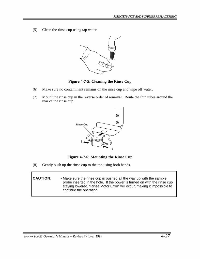
MAINTENANCE AND SUPPLIES REPLACEMENT
Sysmex KX-21 Operator’s Manual -- Revised October 1998 4-27
(5) Clean the rinse cup using tap water.
Figure 4-7-5: Cleaning the Rinse Cup
(6) Make sure no contaminant remains on the rinse cup and wipe off water.
(7) Mount the rinse cup in the reverse order of removal. Route the thin tubes around therear of the rinse cup.
Rinse Cup
3
2
1
Figure 4-7-6: Mounting the Rinse Cup
(8) Gently push up the rinse cup to the top using both hands.
CAUTION: • Make sure the rinse cup is pushed all the way up with the sampleprobe inserted in the hole. If the power is turned on with the rinse cupstaying lowered, "Rinse Motor Error" will occur, making it impossible tocontinue the operation.
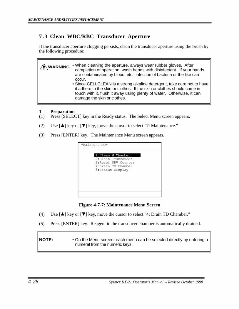
MAINTENANCE AND SUPPLIES REPLACEMENT
4-28 Sysmex KX-21 Operator’s Manual -- Revised October 1998
7 .3 Clean WBC/RBC Transducer Aperture
If the transducer aperture clogging persists, clean the transducer aperture using the brush bythe following procedure:
• When cleaning the aperture, always wear rubber gloves. Aftercompletion of operation, wash hands with disinfectant. If your handsare contaminated by blood, etc., infection of bacteria or the like canoccur.
• Since CELLCLEAN is a strong alkaline detergent, take care not to haveit adhere to the skin or clothes. If the skin or clothes should come intouch with it, flush it away using plenty of water. Otherwise, it candamage the skin or clothes.
1. Preparation(1) Press [SELECT] key in the Ready status. The Select Menu screen appears.
(2) Use [ ] key or [ ] key, move the cursor to select "7: Maintenance."
(3) Press [ENTER] key. The Maintenance Menu screen appears.
*Maintenance*
1:Clean W.Chamber2:Clean Transducer3:Reset SRV Counter4:Drain TD Chamber5:Status Display
Figure 4-7-7: Maintenance Menu Screen
(4) Use [ ] key or [ ] key, move the cursor to select "4: Drain TD Chamber."
(5) Press [ENTER] key. Reagent in the transducer chamber is automatically drained.
NOTE: • On the Menu screen, each menu can be selected directly by entering anumeral from the numeric keys.
WARNING
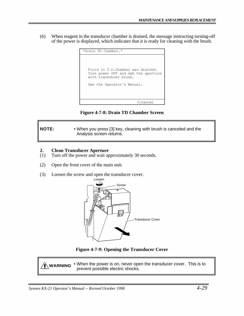
MAINTENANCE AND SUPPLIES REPLACEMENT
Sysmex KX-21 Operator’s Manual -- Revised October 1998 4-29
(6) When reagent in the transducer chamber is drained, the message instructing turning-offof the power is displayed, which indicates that it is ready for cleaning with the brush.
*Drain TD Chamber.*
3:Cancel
Fluid in T.D.Chamber was drained.Turn power OFF and dab the aperturewith transducer brush.
See the Operator's Manual.
Figure 4-7-8: Drain TD Chamber Screen
NOTE: • When you press [3] key, cleaning with brush is canceled and theAnalysis screen returns.
2. Clean Transducer Aperture(1) Turn off the power and wait approximately 30 seconds.
(2) Open the front cover of the main unit.
(3) Loosen the screw and open the transducer cover.
Transducer Cover
Loosen
Screw
Figure 4-7-9: Opening the Transducer Cover
• When the power is on, never open the transducer cover. This is toprevent possible electric shocks.
WARNING
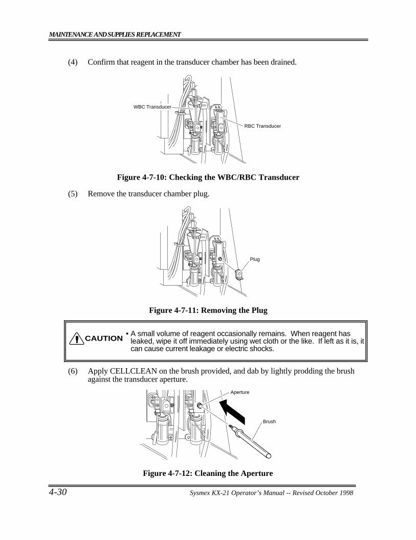
MAINTENANCE AND SUPPLIES REPLACEMENT
4-30 Sysmex KX-21 Operator’s Manual -- Revised October 1998
(4) Confirm that reagent in the transducer chamber has been drained.
RBC Transducer
WBC Transducer
Figure 4-7-10: Checking the WBC/RBC Transducer
(5) Remove the transducer chamber plug.
Plug
Figure 4-7-11: Removing the Plug
• A small volume of reagent occasionally remains. When reagent hasleaked, wipe it off immediately using wet cloth or the like. If left as it is, itcan cause current leakage or electric shocks.
(6) Apply CELLCLEAN on the brush provided, and dab by lightly prodding the brushagainst the transducer aperture.
Brush
Aperture
Figure 4-7-12: Cleaning the Aperture
CAUTION
MAINTENANCE AND SUPPLIES REPLACEMENT
Sysmex KX-21 Operator’s Manual -- Revised October 1998 4-31
NOTE: • After using the brush, wash it in water thoroughly to removeCELLCLEAN before storing it.
(7) Mount the transducer chamber plug.
• The transducer chamber plug should be mounted securely. Otherwise,current leakage or electric shocks can occur.
(8) Close the transducer cover and main unit front cover. Then turn on the power.
(9) Check to see that background error has not occurred.
CAUTION
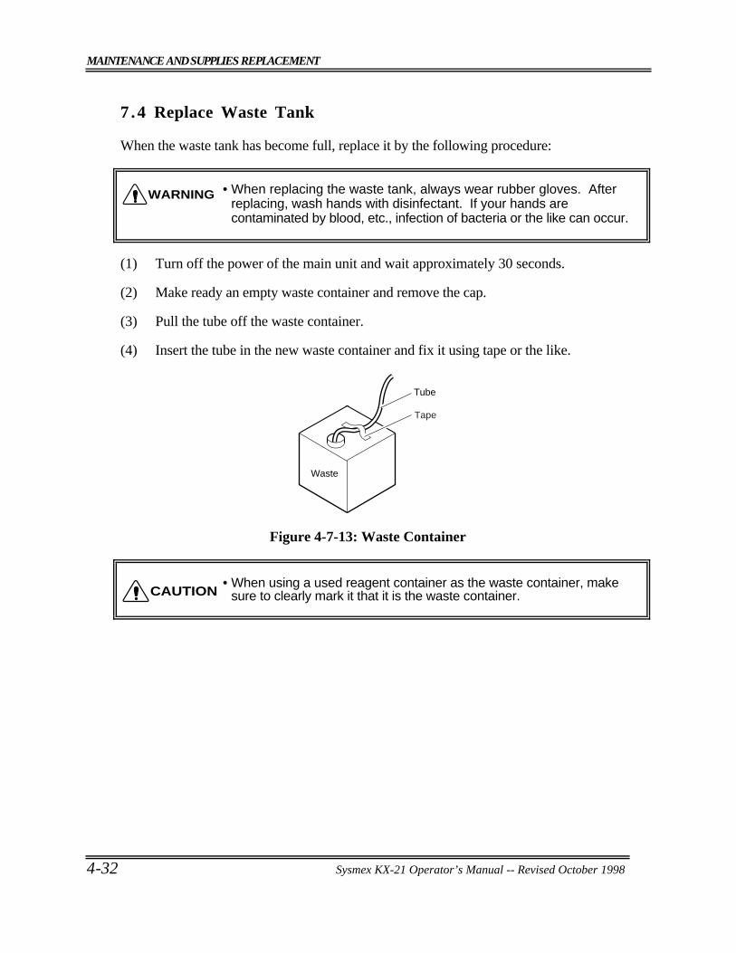
MAINTENANCE AND SUPPLIES REPLACEMENT
4-32 Sysmex KX-21 Operator’s Manual -- Revised October 1998
7 .4 Replace Waste Tank
When the waste tank has become full, replace it by the following procedure:
• When replacing the waste tank, always wear rubber gloves. Afterreplacing, wash hands with disinfectant. If your hands arecontaminated by blood, etc., infection of bacteria or the like can occur.
(1) Turn off the power of the main unit and wait approximately 30 seconds.
(2) Make ready an empty waste container and remove the cap.
(3) Pull the tube off the waste container.
(4) Insert the tube in the new waste container and fix it using tape or the like.
Tube
Waste
Tape
Figure 4-7-13: Waste Container
• When using a used reagent container as the waste container, makesure to clearly mark it that it is the waste container.
WARNING
CAUTION
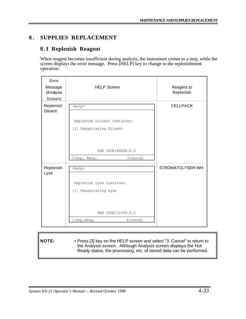
MAINTENANCE AND SUPPLIES REPLACEMENT
Sysmex KX-21 Operator’s Manual -- Revised October 1998 4-33
8 . SUPPLIES REPLACEMENT
8.1 Replenish Reagent
When reagent becomes insufficient during analysis, the instrument comes to a stop, while thescreen displays the error message. Press [HELP] key to change to the replenishmentoperation.
Error
Message(Analysis
Screen)
HELP Screen Reagent toReplenish
ReplenishDiluent
*Help*
Replenish Diluent Container.
ERR CODE:XXXXX.X.X
Reaspirating Diluent[1]
1:Asp. Reag. 3:Cancel
CELLPACK
ReplenishLyse
1:Asp.Reag.
ERR CODE:12490.0.0
*Help*
3:Cancel
Replenish Lyse Container.
Reaspirating Lyse[1]
STROMATOLYSER-WH
NOTE: • Press [3] key on the HELP screen and select "3: Cancel" to return tothe Analysis screen. Although Analysis screen displays the NotReady status, the processing, etc. of stored data can be performed.
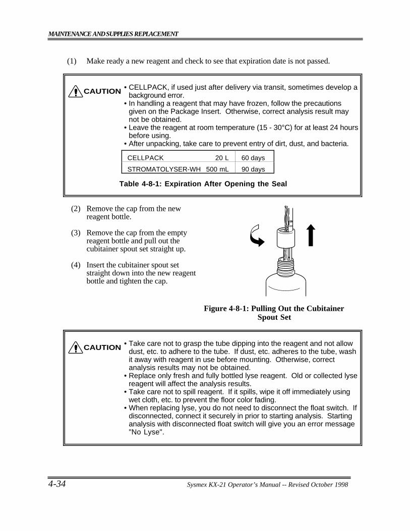
MAINTENANCE AND SUPPLIES REPLACEMENT
4-34 Sysmex KX-21 Operator’s Manual -- Revised October 1998
(1) Make ready a new reagent and check to see that expiration date is not passed.
• CELLPACK, if used just after delivery via transit, sometimes develop abackground error.
• In handling a reagent that may have frozen, follow the precautionsgiven on the Package Insert. Otherwise, correct analysis result maynot be obtained.
• Leave the reagent at room temperature (15 - 30°C) for at least 24 hoursbefore using.
• After unpacking, take care to prevent entry of dirt, dust, and bacteria.
Table 4-8-1: Expiration After Opening the Seal
(2) Remove the cap from the newreagent bottle.
(3) Remove the cap from the emptyreagent bottle and pull out thecubitainer spout set straight up.
(4) Insert the cubitainer spout setstraight down into the new reagentbottle and tighten the cap.
Figure 4-8-1: Pulling Out the CubitainerSpout Set
• Take care not to grasp the tube dipping into the reagent and not allowdust, etc. to adhere to the tube. If dust, etc. adheres to the tube, washit away with reagent in use before mounting. Otherwise, correctanalysis results may not be obtained.
• Replace only fresh and fully bottled lyse reagent. Old or collected lysereagent will affect the analysis results.
• Take care not to spill reagent. If it spills, wipe it off immediately usingwet cloth, etc. to prevent the floor color fading.
• When replacing lyse, you do not need to disconnect the float switch. Ifdisconnected, connect it securely in prior to starting analysis. Startinganalysis with disconnected float switch will give you an error message"No Lyse".
CAUTION
CAUTION
CELLPACK 20 L 60 days
STROMATOLYSER-WH 500 mL 90 days
MAINTENANCE AND SUPPLIES REPLACEMENT
Sysmex KX-21 Operator’s Manual -- Revised October 1998 4-35
(5) When reagent replenishment is over, follow the instruction on the screen and press [1]key to select "1: Asp. Reag." Reagent is automatically aspirated, and then backgroundcheck is performed. The check is made here to see that background error has notoccurred.
(6) Enter the contents of replenishment in Reagent Replenishment Record.
NOTE: • If you replenish lyse before error message "No Reagent" appears,execute "4: Replace Lyse" on the Select Menu screen.
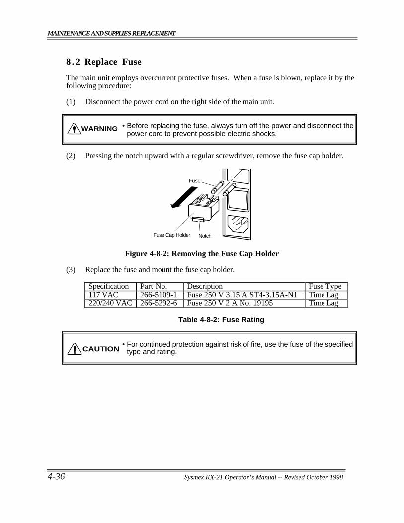
MAINTENANCE AND SUPPLIES REPLACEMENT
4-36 Sysmex KX-21 Operator’s Manual -- Revised October 1998
8 .2 Replace Fuse
The main unit employs overcurrent protective fuses. When a fuse is blown, replace it by thefollowing procedure:
(1) Disconnect the power cord on the right side of the main unit.
• Before replacing the fuse, always turn off the power and disconnect thepower cord to prevent possible electric shocks.
(2) Pressing the notch upward with a regular screwdriver, remove the fuse cap holder.
Fuse
Fuse Cap Holder Notch
Figure 4-8-2: Removing the Fuse Cap Holder
(3) Replace the fuse and mount the fuse cap holder.
Specification Part No. Description Fuse Type117 VAC 266-5109-1 Fuse 250 V 3.15 A ST4-3.15A-N1 Time Lag220/240 VAC 266-5292-6 Fuse 250 V 2 A No. 19195 Time Lag
Table 4-8-2: Fuse Rating
• For continued protection against risk of fire, use the fuse of the specifiedtype and rating.
WARNING
CAUTION
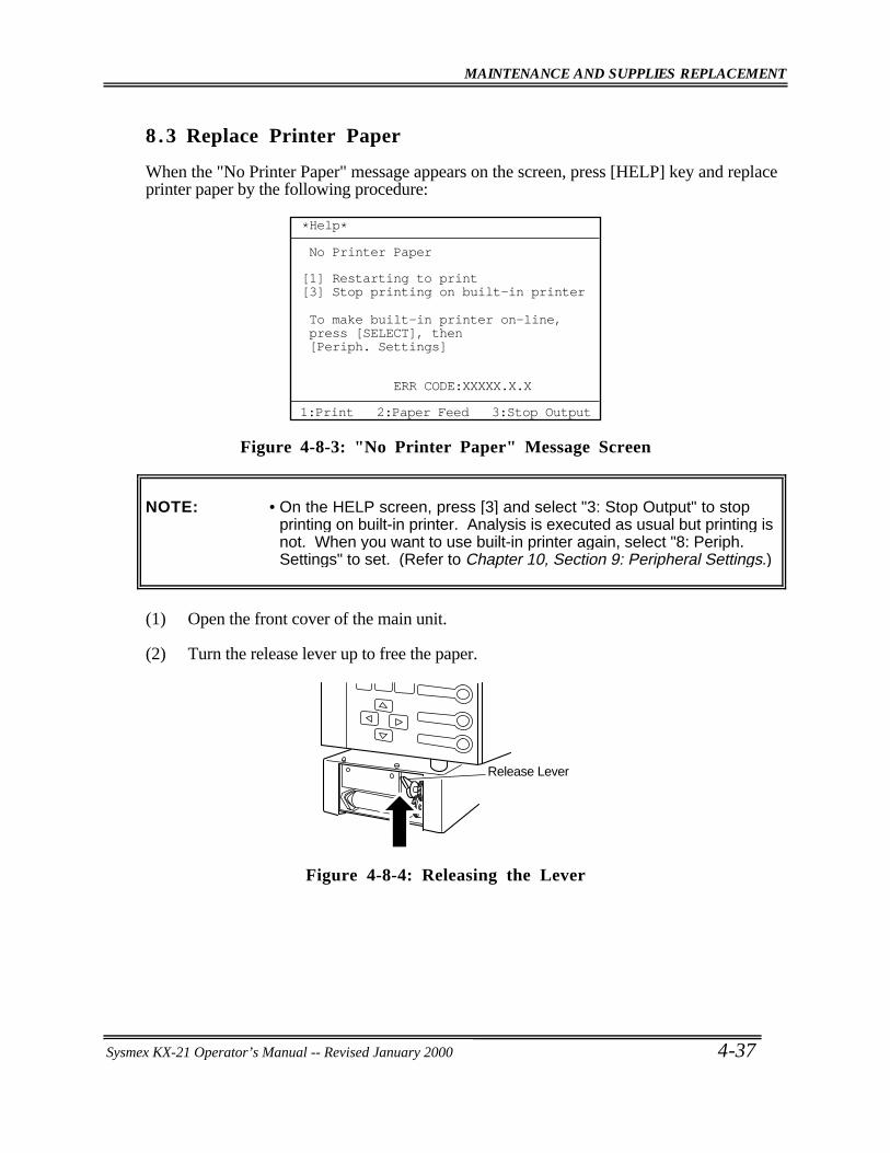
MAINTENANCE AND SUPPLIES REPLACEMENT
Sysmex KX-21 Operator’s Manual -- Revised October 1998 4-37
8 .3 Replace Printer Paper
When the "No Printer Paper" message appears on the screen, press [HELP] key and replaceprinter paper by the following procedure:
*Help*
No Printer Paper
ERR CODE:XXXXX.X.X
Restarting to print Stop printing on built-in printer[1][3]
To make built-in printer on-line,press [SELECT], then[Periph. Settings]
1:Print 2:Paper Feed 3:Stop Output
Figure 4-8-3: "No Printer Paper" Message Screen
NOTE: • On the HELP screen, press [3] and select "3: Stop Output" to stopprinting on built-in printer. Analysis is executed as usual but printing isnot. When you want to use built-in printer again, select "8: Periph.Settings" to set. (Refer to Chapter 10, Section 9: Peripheral Settings.)
(1) Open the front cover of the main unit.
(2) Turn the release lever up to free the paper.
Release Lever
Figure 4-8-4: Releasing the Lever
Sysmex KX-21 Operator’s Manual -- Revised January 2000
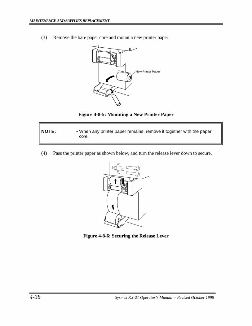
MAINTENANCE AND SUPPLIES REPLACEMENT
4-38 Sysmex KX-21 Operator’s Manual -- Revised October 1998
(3) Remove the bare paper core and mount a new printer paper.
New Printer Paper
Figure 4-8-5: Mounting a New Printer Paper
NOTE: • When any printer paper remains, remove it together with the papercore.
(4) Pass the printer paper as shown below, and turn the release lever down to secure.
Figure 4-8-6: Securing the Release Lever
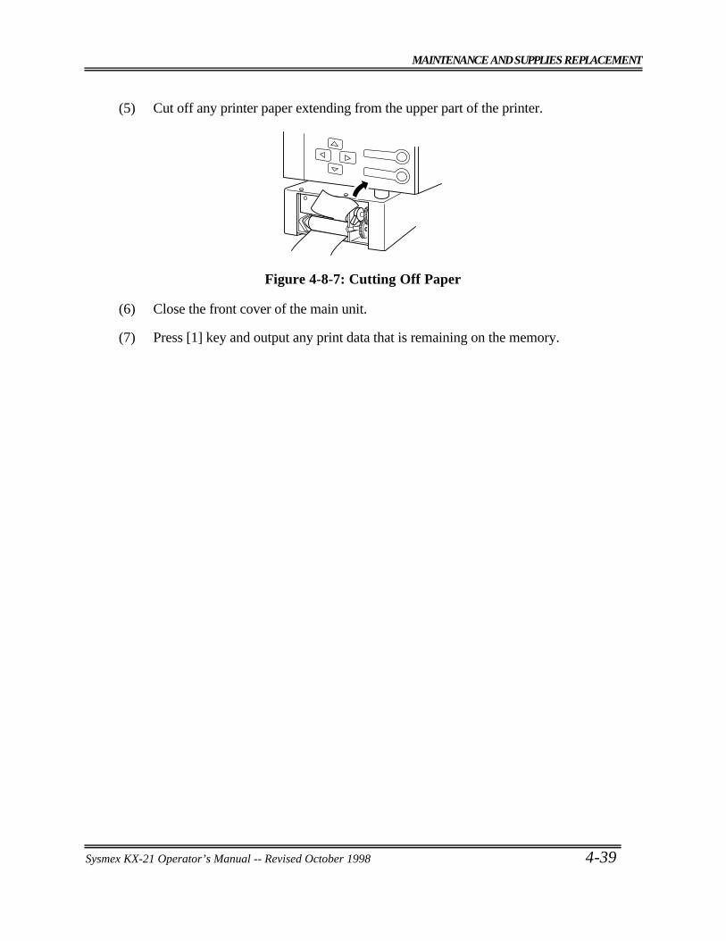
MAINTENANCE AND SUPPLIES REPLACEMENT
Sysmex KX-21 Operator’s Manual -- Revised October 1998 4-39
(5) Cut off any printer paper extending from the upper part of the printer.
Figure 4-8-7: Cutting Off Paper
(6) Close the front cover of the main unit.
(7) Press [1] key and output any print data that is remaining on the memory.
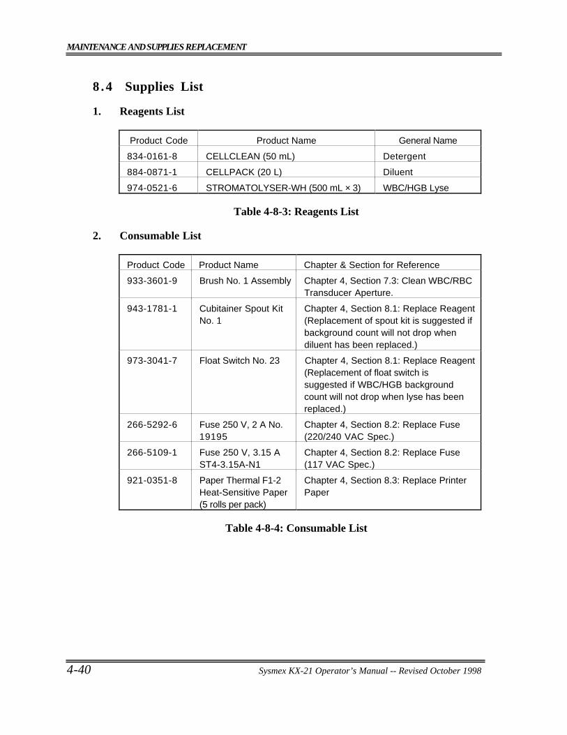
MAINTENANCE AND SUPPLIES REPLACEMENT
4-40 Sysmex KX-21 Operator’s Manual -- Revised October 1998
8 .4 Supplies List
1. Reagents List
Product Code Product Name General Name
834-0161-8 CELLCLEAN (50 mL) Detergent
884-0871-1 CELLPACK (20 L) Diluent
974-0521-6 STROMATOLYSER-WH (500 mL × 3) WBC/HGB Lyse
Table 4-8-3: Reagents List
2. Consumable List
Product Code Product Name Chapter & Section for Reference
933-3601-9 Brush No. 1 Assembly Chapter 4, Section 7.3: Clean WBC/RBCTransducer Aperture.
943-1781-1 Cubitainer Spout KitNo. 1
Chapter 4, Section 8.1: Replace Reagent(Replacement of spout kit is suggested ifbackground count will not drop whendiluent has been replaced.)
973-3041-7 Float Switch No. 23 Chapter 4, Section 8.1: Replace Reagent(Replacement of float switch issuggested if WBC/HGB backgroundcount will not drop when lyse has beenreplaced.)
266-5292-6 Fuse 250 V, 2 A No.19195
Chapter 4, Section 8.2: Replace Fuse(220/240 VAC Spec.)
266-5109-1 Fuse 250 V, 3.15 AST4-3.15A-N1
Chapter 4, Section 8.2: Replace Fuse(117 VAC Spec.)
921-0351-8 Paper Thermal F1-2Heat-Sensitive Paper(5 rolls per pack)
Chapter 4, Section 8.3: Replace PrinterPaper
Table 4-8-4: Consumable List
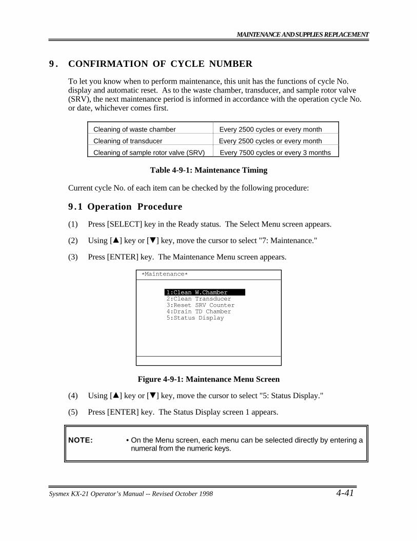
MAINTENANCE AND SUPPLIES REPLACEMENT
Sysmex KX-21 Operator’s Manual -- Revised October 1998 4-41
9 . CONFIRMATION OF CYCLE NUMBER
To let you know when to perform maintenance, this unit has the functions of cycle No.display and automatic reset. As to the waste chamber, transducer, and sample rotor valve(SRV), the next maintenance period is informed in accordance with the operation cycle No.or date, whichever comes first.
Cleaning of waste chamber Every 2500 cycles or every month
Cleaning of transducer Every 2500 cycles or every month
Cleaning of sample rotor valve (SRV) Every 7500 cycles or every 3 months
Table 4-9-1: Maintenance Timing
Current cycle No. of each item can be checked by the following procedure:
9 .1 Operation Procedure
(1) Press [SELECT] key in the Ready status. The Select Menu screen appears.
(2) Using [ ] key or [ ] key, move the cursor to select "7: Maintenance."
(3) Press [ENTER] key. The Maintenance Menu screen appears.
*Maintenance*
1:Clean W.Chamber2:Clean Transducer3:Reset SRV Counter4:Drain TD Chamber5:Status Display
Figure 4-9-1: Maintenance Menu Screen
(4) Using [ ] key or [ ] key, move the cursor to select "5: Status Display."
(5) Press [ENTER] key. The Status Display screen 1 appears.
NOTE: • On the Menu screen, each menu can be selected directly by entering anumeral from the numeric keys.
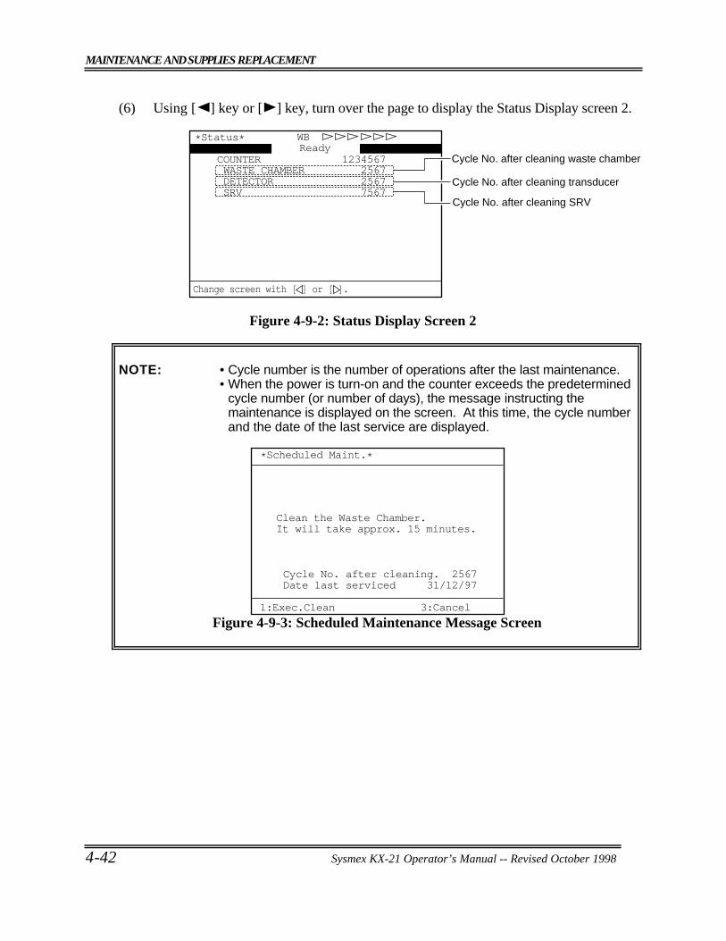
MAINTENANCE AND SUPPLIES REPLACEMENT
4-42 Sysmex KX-21 Operator’s Manual -- Revised October 1998
(6) Using [ ] key or [ ] key, turn over the page to display the Status Display screen 2.
COUNTER 1234567
SRV 7567 DETECTOR 2567 WASTE CHAMBER 2567
WBReady
*Status*
Cycle No. after cleaning waste chamber
Cycle No. after cleaning transducer
Cycle No. after cleaning SRV
Change screen with [ ] or [ ].
Figure 4-9-2: Status Display Screen 2
NOTE: • Cycle number is the number of operations after the last maintenance.• When the power is turn-on and the counter exceeds the predetermined
cycle number (or number of days), the message instructing themaintenance is displayed on the screen. At this time, the cycle numberand the date of the last service are displayed.
*Scheduled Maint.*
1:Exec.Clean 3:Cancel
Clean the Waste Chamber.It will take approx. 15 minutes.
Cycle No. after cleaning. 2567Date last serviced 31/12/97
Figure 4-9-3: Scheduled Maintenance Message Screen
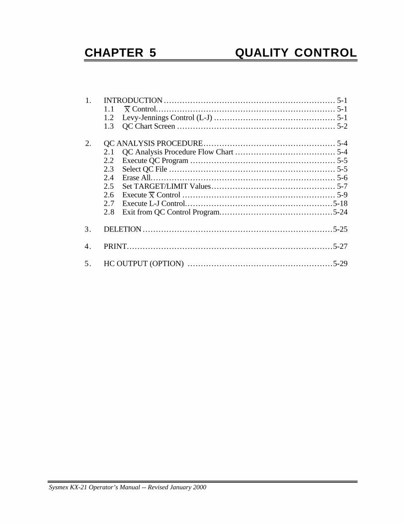
Sysmex KX-21 Operator’s Manual -- Revised January 2000
CHAPTER 5 QUALITY CONTROL
1. INTRODUCTION ... . . . . . . . . . . . . . . . . . . . . . . . . . . . . . . . . . . . . . . . . . . . . . . . . . . . . . . . . . . . . . . 5-11.1 X Control. . . . . . . . . . . . . . . . . . . . . . . . . . . . . . . . . . . . . . . . . . . . . . . . . . . . . . . . . . . . . . . . . . . . 5-11.2 Levy-Jennings Control (L-J) .. . . . . . . . . . . . . . . . . . . . . . . . . . . . . . . . . . . . . . . . . . . . . 5-11.3 QC Chart Screen .. . . . . . . . . . . . . . . . . . . . . . . . . . . . . . . . . . . . . . . . . . . . . . . . . . . . . . . . . . . 5-2
2. QC ANALYSIS PROCEDURE... . . . . . . . . . . . . . . . . . . . . . . . . . . . . . . . . . . . . . . . . . . . . . . . 5-42.1 QC Analysis Procedure Flow Chart . . . . . . . . . . . . . . . . . . . . . . . . . . . . . . . . . . . . . . 5-42.2 Execute QC Program ... . . . . . . . . . . . . . . . . . . . . . . . . . . . . . . . . . . . . . . . . . . . . . . . . . . . . 5-52.3 Select QC File .. . . . . . . . . . . . . . . . . . . . . . . . . . . . . . . . . . . . . . . . . . . . . . . . . . . . . . . . . . . . . . 5-52.4 Erase All. . . . . . . . . . . . . . . . . . . . . . . . . . . . . . . . . . . . . . . . . . . . . . . . . . . . . . . . . . . . . . . . . . . . . . 5-62.5 Set TARGET/LIMIT Values.. . . . . . . . . . . . . . . . . . . . . . . . . . . . . . . . . . . . . . . . . . . . . . 5-72.6 Execute X Control . . . . . . . . . . . . . . . . . . . . . . . . . . . . . . . . . . . . . . . . . . . . . . . . . . . . . . . . . . 5-92.7 Execute L-J Control. . . . . . . . . . . . . . . . . . . . . . . . . . . . . . . . . . . . . . . . . . . . . . . . . . . . . . . .5-182.8 Exit from QC Control Program... . . . . . . . . . . . . . . . . . . . . . . . . . . . . . . . . . . . . . . . .5-24
3. DELETION ... . . . . . . . . . . . . . . . . . . . . . . . . . . . . . . . . . . . . . . . . . . . . . . . . . . . . . . . . . . . . . . . . . . . . .5-25
4. PRINT... . . . . . . . . . . . . . . . . . . . . . . . . . . . . . . . . . . . . . . . . . . . . . . . . . . . . . . . . . . . . . . . . . . . . . . . . . . .5-27
5. HC OUTPUT (OPTION) .. . . . . . . . . . . . . . . . . . . . . . . . . . . . . . . . . . . . . . . . . . . . . . . . . . . . . .5-29
QUALITY CONTROL
Sysmex KX-21 Operator’s Manual -- Revised October 1998 5-1
1 . INTRODUCTION
Quality Control checks are performed to monitor an instrument’s performance over time.EIGHTCHECK-3WP is the quality control material recommended by Sysmex to monitor theperformance of the KX-21 analyzer. This product is supplied with three control levels, atleast two levels should be run every 8 hours of operation or in accordance to regulationsapplicable to your laboratory. Quality control material should be run after componentreplacement or after a service call. The KX-21 has two quality control methods.
1 .1 X Control
In X control, control blood is analyzed twice and the mean of the two is used to evaluateanalyzer performance.
1 .2 Levy-Jennings Control (L-J)
The L-J control uses the data from a single control blood analysis to evaluated analyzerperformance.
NOTE: • Selection of the one of the two methods can be performed using QCmethod in the QC Settings program. Rrefer to "Chapter 10, Section 5:QC Settings."
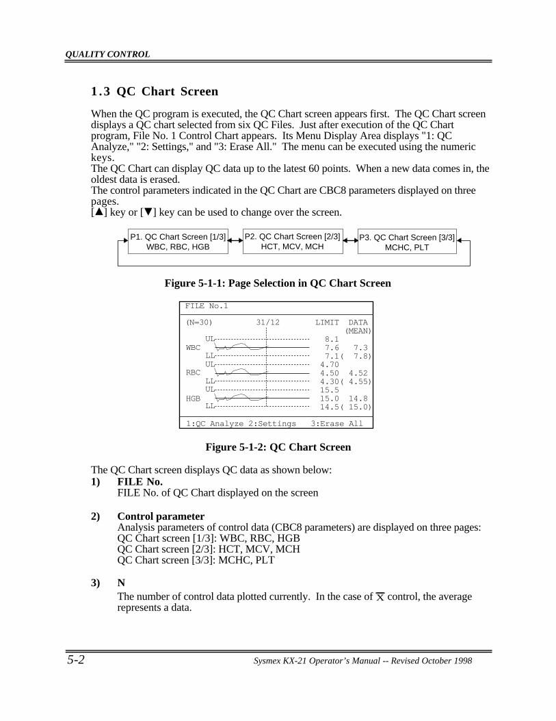
QUALITY CONTROL
5-2 Sysmex KX-21 Operator’s Manual -- Revised October 1998
1 .3 QC Chart Screen
When the QC program is executed, the QC Chart screen appears first. The QC Chart screendisplays a QC chart selected from six QC Files. Just after execution of the QC Chartprogram, File No. 1 Control Chart appears. Its Menu Display Area displays "1: QCAnalyze," "2: Settings," and "3: Erase All." The menu can be executed using the numerickeys.The QC Chart can display QC data up to the latest 60 points. When a new data comes in, theoldest data is erased.The control parameters indicated in the QC Chart are CBC8 parameters displayed on threepages.[ ] key or [ ] key can be used to change over the screen.
P2. QC Chart Screen [2/3]HCT, MCV, MCH
P3. QC Chart Screen [3/3]MCHC, PLT
P1. QC Chart Screen [1/3]WBC, RBC, HGB
Figure 5-1-1: Page Selection in QC Chart Screen
(N=30) 31/12
ULWBC
RBC
HGB
LLUL
LLUL
LL
LIMIT DATA (MEAN) 8.1 7.6 7.3 7.1( 7.8) 4.70 4.50 4.52 4.30( 4.55) 15.5 15.0 14.8 14.5( 15.0)
FILE No.1
1:QC Analyze 2:Settings 3:Erase All
Figure 5-1-2: QC Chart Screen
The QC Chart screen displays QC data as shown below:1) FILE No.
FILE No. of QC Chart displayed on the screen
2) Control parameterAnalysis parameters of control data (CBC8 parameters) are displayed on three pages:QC Chart screen [1/3]: WBC, RBC, HGBQC Chart screen [2/3]: HCT, MCV, MCHQC Chart screen [3/3]: MCHC, PLT
3) NThe number of control data plotted currently. In the case of X control, the averagerepresents a data.
QUALITY CONTROL
Sysmex KX-21 Operator’s Manual -- Revised October 1998 5-3
4) LIMIT (UL)The upper control limit. An analysis value exceeding this limit is a QC error.
5) LIMIT (LL)The lower control limit. An analysis value exceeding this limit is a QC error.
6) Target valueQC Target value
7) DATAThe QC data of the plot specified by the vertical line cursor. In the case of X control, itis the mean value of two consecutive analyses.
8) MEANThe mean of QC data plotted currently
9) Line CursorThe vertical line cursor can be moved to the right or left using [ ] key or [ ] key.The QC data of the plot shown by the line cursor, along with analysis date, aredisplayed.
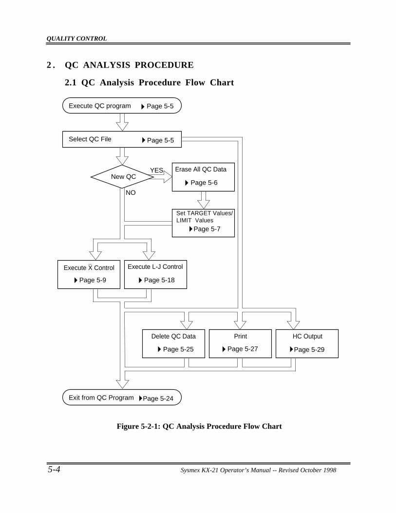
QUALITY CONTROL
5-4 Sysmex KX-21 Operator’s Manual -- Revised October 1998
2 . QC ANALYSIS PROCEDURE
2.1 QC Analysis Procedure Flow Chart
Execute QC program
Exit from QC Program
Select QC File
New QC YES
NO
Erase All QC Data
Execute L-J ControlExecute X Control
Set TARGET Values/LIMIT Values
Delete QC Data Print HC Output
Page 5-5
Page 5-5
Page 5-18
Page 5-6
Page 5-7
Page 5-9
Page 5-25
Page 5-24
Page 5-27 Page 5-29
Figure 5-2-1: QC Analysis Procedure Flow Chart
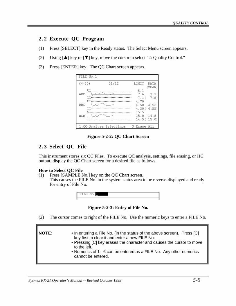
QUALITY CONTROL
Sysmex KX-21 Operator’s Manual -- Revised October 1998 5-5
2 .2 Execute QC Program
(1) Press [SELECT] key in the Ready status. The Select Menu screen appears.
(2) Using [ ] key or [ ] key, move the cursor to select "2: Quality Control."
(3) Press [ENTER] key. The QC Chart screen appears.
(N=30) 31/12
ULWBC
RBC
HGB
LLUL
LLUL
LL
LIMIT DATA (MEAN) 8.1 7.6 7.3 7.1( 7.8) 4.70 4.50 4.52 4.30( 4.55) 15.5 15.0 14.8 14.5( 15.0)
FILE No.1
1:QC Analyze 2:Settings 3:Erase All
Figure 5-2-2: QC Chart Screen
2 .3 Select QC File
This instrument stores six QC Files. To execute QC analysis, settings, file erasing, or HCoutput, display the QC Chart screen for a desired file as follows.
How to Select QC File(1) Press [SAMPLE No.] key on the QC Chart screen.
This causes the FILE No. in the system status area to be reverse-displayed and readyfor entry of File No.
FILE No.1
Figure 5-2-3: Entry of File No.
(2) The cursor comes to right of the FILE No. Use the numeric keys to enter a FILE No.
NOTE: • In entering a File No. (in the status of the above screen). Press [C]key first to clear it and enter a new FILE No.
• Pressing [C] key erases the character and causes the cursor to moveto the left.
• Numerics of 1 - 6 can be entered as a FILE No. Any other numericscannot be entered.
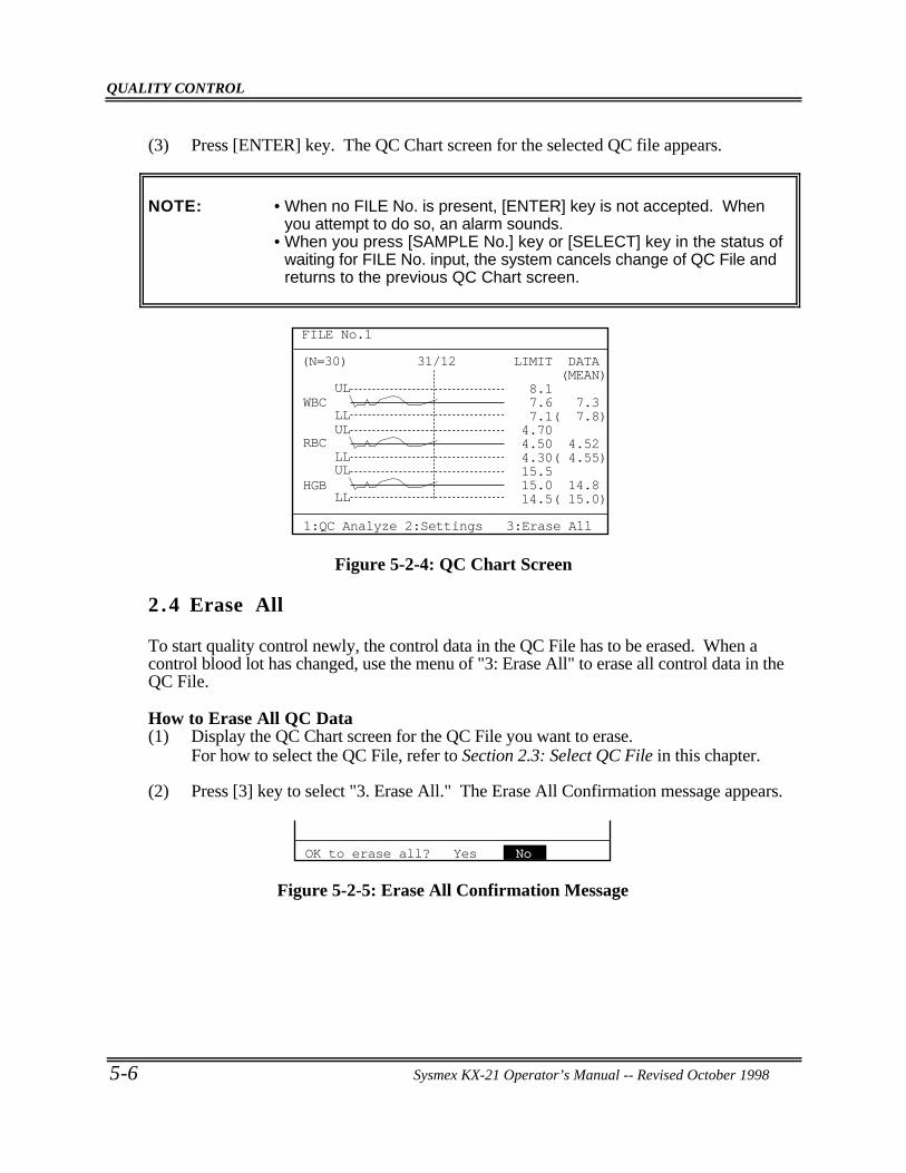
QUALITY CONTROL
5-6 Sysmex KX-21 Operator’s Manual -- Revised October 1998
(3) Press [ENTER] key. The QC Chart screen for the selected QC file appears.
NOTE: • When no FILE No. is present, [ENTER] key is not accepted. Whenyou attempt to do so, an alarm sounds.
• When you press [SAMPLE No.] key or [SELECT] key in the status ofwaiting for FILE No. input, the system cancels change of QC File andreturns to the previous QC Chart screen.
(N=30) 31/12
ULWBC
RBC
HGB
LLUL
LLUL
LL
LIMIT DATA (MEAN) 8.1 7.6 7.3 7.1( 7.8) 4.70 4.50 4.52 4.30( 4.55) 15.5 15.0 14.8 14.5( 15.0)
FILE No.1
1:QC Analyze 2:Settings 3:Erase All
Figure 5-2-4: QC Chart Screen
2 .4 Erase All
To start quality control newly, the control data in the QC File has to be erased. When acontrol blood lot has changed, use the menu of "3: Erase All" to erase all control data in theQC File.
How to Erase All QC Data(1) Display the QC Chart screen for the QC File you want to erase.
For how to select the QC File, refer to Section 2.3: Select QC File in this chapter.
(2) Press [3] key to select "3. Erase All." The Erase All Confirmation message appears.
OK to erase all? Yes No
Figure 5-2-5: Erase All Confirmation Message
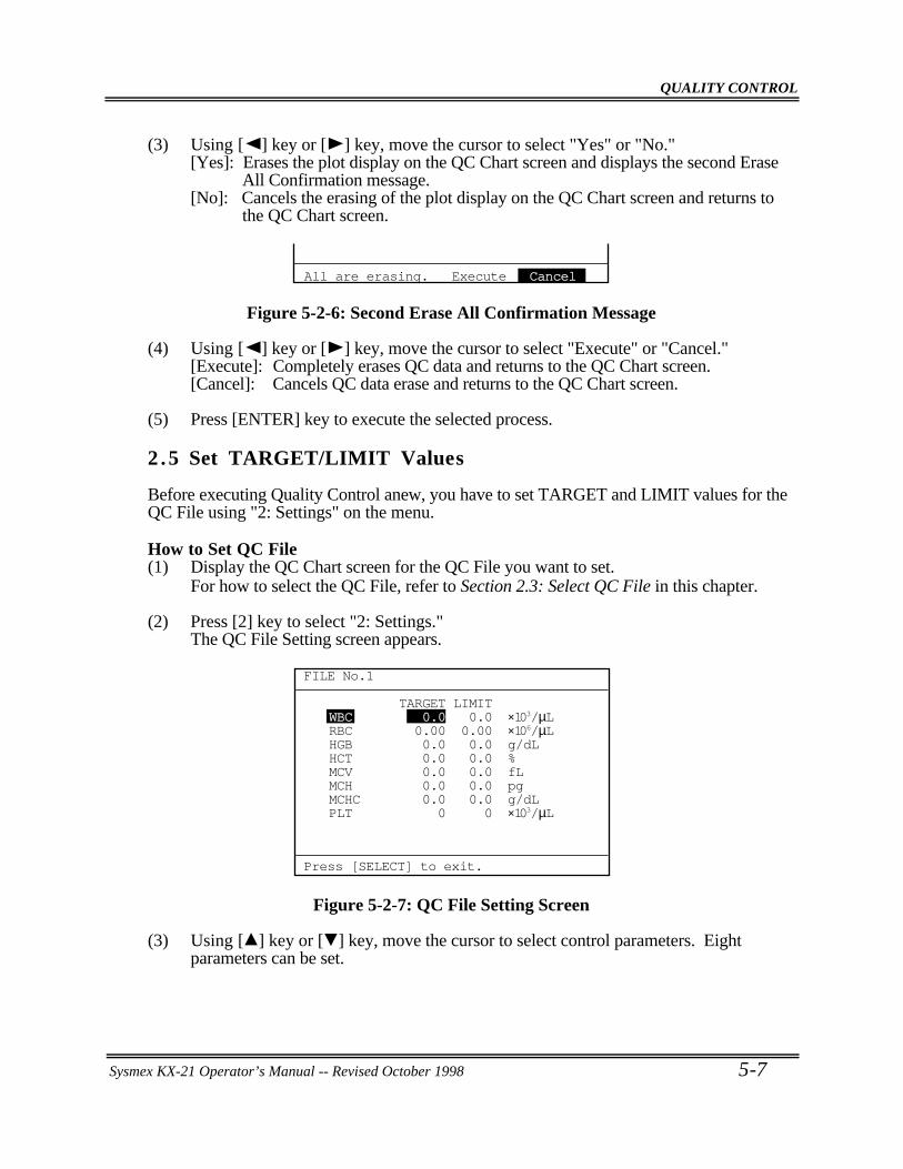
QUALITY CONTROL
Sysmex KX-21 Operator’s Manual -- Revised October 1998 5-7
(3) Using [ ] key or [ ] key, move the cursor to select "Yes" or "No."[Yes]: Erases the plot display on the QC Chart screen and displays the second Erase
All Confirmation message.[No]: Cancels the erasing of the plot display on the QC Chart screen and returns to
the QC Chart screen.
All are erasing. Execute Cancel
Figure 5-2-6: Second Erase All Confirmation Message
(4) Using [ ] key or [ ] key, move the cursor to select "Execute" or "Cancel."[Execute]: Completely erases QC data and returns to the QC Chart screen.[Cancel]: Cancels QC data erase and returns to the QC Chart screen.
(5) Press [ENTER] key to execute the selected process.
2 .5 Set TARGET/LIMIT Values
Before executing Quality Control anew, you have to set TARGET and LIMIT values for theQC File using "2: Settings" on the menu.
How to Set QC File(1) Display the QC Chart screen for the QC File you want to set.
For how to select the QC File, refer to Section 2.3: Select QC File in this chapter.
(2) Press [2] key to select "2: Settings."The QC File Setting screen appears.
FILE No.1
Press [SELECT] to exit.
TARGET LIMITWBC 0.0 0.0 ×10³/µLRBC 0.00 0.00 ×10⁶/µLHGB 0.0 0.0 g/dLHCT 0.0 0.0 %MCV 0.0 0.0 fLMCH 0.0 0.0 pgMCHC 0.0 0.0 g/dLPLT 0 0 ×103/µL
Figure 5-2-7: QC File Setting Screen
(3) Using [ ] key or [ ] key, move the cursor to select control parameters. Eightparameters can be set.
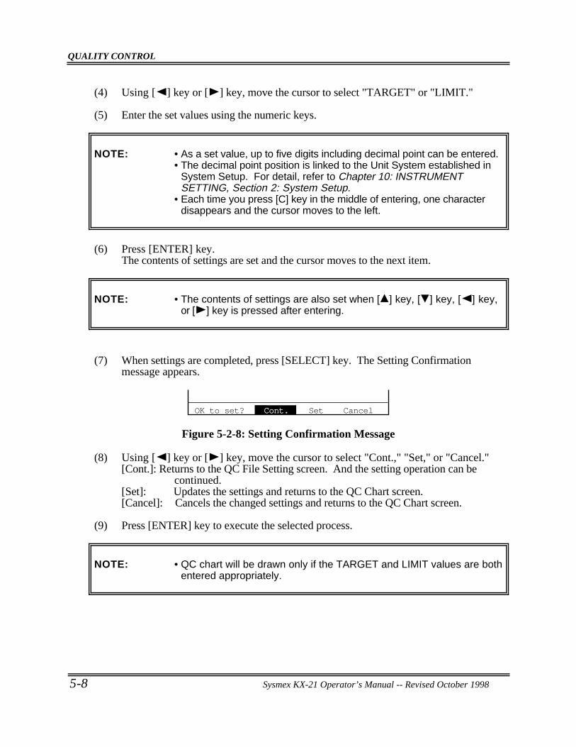
QUALITY CONTROL
5-8 Sysmex KX-21 Operator’s Manual -- Revised October 1998
(4) Using [ ] key or [ ] key, move the cursor to select "TARGET" or "LIMIT."
(5) Enter the set values using the numeric keys.
NOTE: • As a set value, up to five digits including decimal point can be entered.• The decimal point position is linked to the Unit System established in
System Setup. For detail, refer to Chapter 10: INSTRUMENTSETTING, Section 2: System Setup.
• Each time you press [C] key in the middle of entering, one characterdisappears and the cursor moves to the left.
(6) Press [ENTER] key.The contents of settings are set and the cursor moves to the next item.
NOTE: • The contents of settings are also set when [ ] key, [ ] key, [ ] key,or [ ] key is pressed after entering.
(7) When settings are completed, press [SELECT] key. The Setting Confirmationmessage appears.
OK to set? Cont. Set Cancel
Figure 5-2-8: Setting Confirmation Message
(8) Using [ ] key or [ ] key, move the cursor to select "Cont.," "Set," or "Cancel."[Cont.]: Returns to the QC File Setting screen. And the setting operation can be
continued.[Set]: Updates the settings and returns to the QC Chart screen.[Cancel]: Cancels the changed settings and returns to the QC Chart screen.
(9) Press [ENTER] key to execute the selected process.
NOTE: • QC chart will be drawn only if the TARGET and LIMIT values are bothentered appropriately.
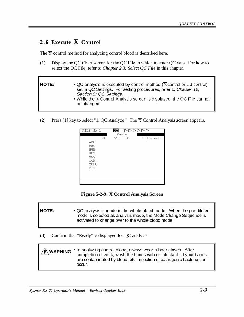
QUALITY CONTROL
Sysmex KX-21 Operator’s Manual -- Revised October 1998 5-9
2 .6 Execute X Control
The X control method for analyzing control blood is described here.
(1) Display the QC Chart screen for the QC File in which to enter QC data. For how toselect the QC File, refer to Chapter 2.3: Select QC File in this chapter.
NOTE: • QC analysis is executed by control method (X control or L-J control)set in QC Settings. For setting procedures, refer to Chapter 10,Section 5: QC Settings.
• While the X Control Analysis screen is displayed, the QC File cannotbe changed.
(2) Press [1] key to select "1: QC Analyze." The X Control Analysis screen appears.
FILE No.1 QC
X1 X2 X JudgementWBCRBCHGBHCTMCVMCHMCHCPLT
Ready
Figure 5-2-9: X Control Analysis Screen
NOTE: • QC analysis is made in the whole blood mode. When the pre-dilutedmode is selected as analysis mode, the Mode Change Sequence isactivated to change over to the whole blood mode.
(3) Confirm that "Ready" is displayed for QC analysis.
• In analyzing control blood, always wear rubber gloves. Aftercompletion of work, wash the hands with disinfectant. If your handsare contaminated by blood, etc., infection of pathogenic bacteria canoccur.
WARNING
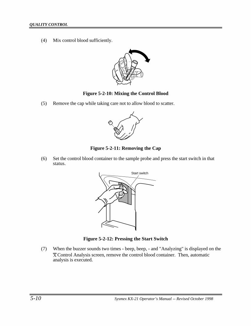
QUALITY CONTROL
5-10 Sysmex KX-21 Operator’s Manual -- Revised October 1998
(4) Mix control blood sufficiently.
Figure 5-2-10: Mixing the Control Blood
(5) Remove the cap while taking care not to allow blood to scatter.
Figure 5-2-11: Removing the Cap
(6) Set the control blood container to the sample probe and press the start switch in thatstatus.
Start switch
Figure 5-2-12: Pressing the Start Switch
(7) When the buzzer sounds two times - beep, beep, - and "Analyzing" is displayed on theX Control Analysis screen, remove the control blood container. Then, automaticanalysis is executed.
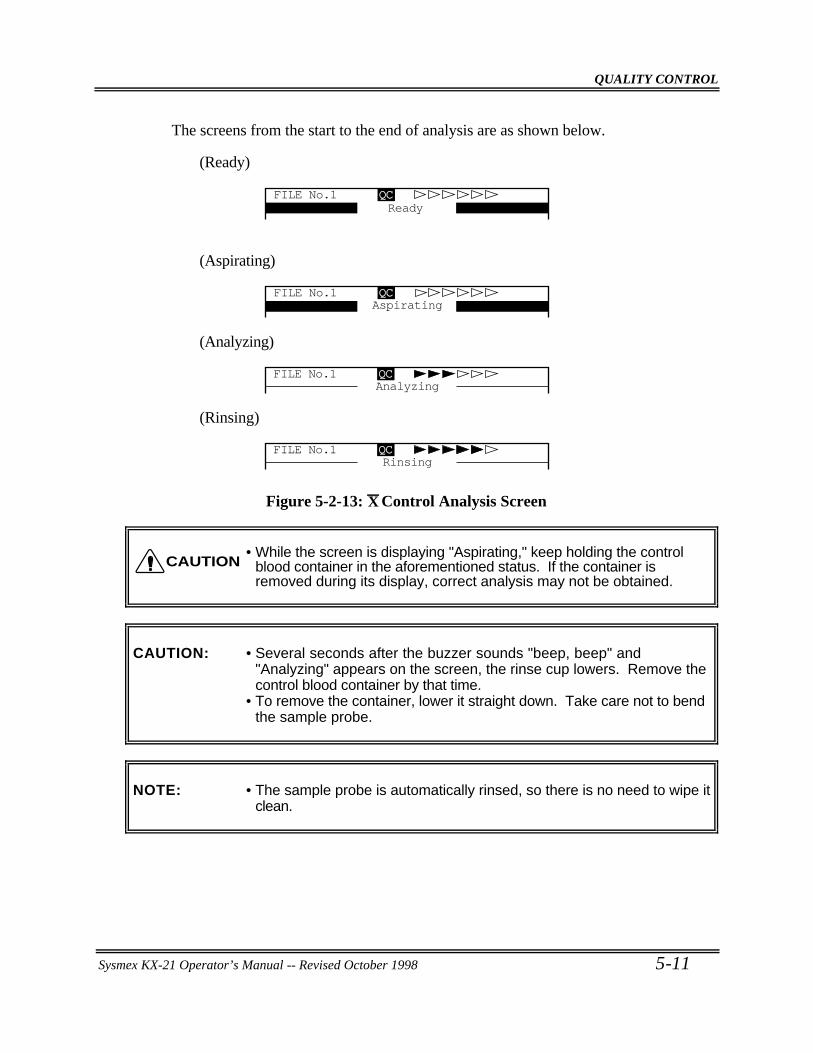
QUALITY CONTROL
Sysmex KX-21 Operator’s Manual -- Revised October 1998 5-11
The screens from the start to the end of analysis are as shown below.
(Ready)
FILE No.1 QCReady
(Aspirating)
AspiratingFILE No.1 QC
(Analyzing)
AnalyzingFILE No.1 QC
(Rinsing)
RinsingFILE No.1 QC
Figure 5-2-13: X Control Analysis Screen
• While the screen is displaying "Aspirating," keep holding the controlblood container in the aforementioned status. If the container isremoved during its display, correct analysis may not be obtained.
CAUTION: • Several seconds after the buzzer sounds "beep, beep" and"Analyzing" appears on the screen, the rinse cup lowers. Remove thecontrol blood container by that time.
• To remove the container, lower it straight down. Take care not to bendthe sample probe.
NOTE: • The sample probe is automatically rinsed, so there is no need to wipe itclean.
CAUTION
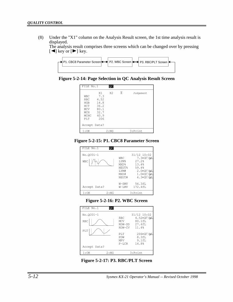
QUALITY CONTROL
5-12 Sysmex KX-21 Operator’s Manual -- Revised October 1998
(8) Under the "X1" column on the Analysis Result screen, the 1st time analysis result isdisplayed.The analysis result comprises three screens which can be changed over by pressing[ ] key or [ ] key.
P2. WBC Screen P3. RBC/PLT ScreenP1. CBC8 Parameter Screen
Figure 5-2-14: Page Selection in QC Analysis Result Screen
FILE No.1 QCQC
X1 X2 X JudgementWBC 7.3RBC 4.52HGB 14.8HCT 36.2MCV 80.1MCH 32.7MCHC 40.9PLT 206
Accept Data?
1:OK 2:NG 3:Print
Figure 5-2-15: P1. CBC8 Parameter Screen
Accept Data?
1:OK 2:NG 3:Print
31/12 10:02No.QC01-1
W-LMV 172.4fLW-SMV 56.3fL
NEUT# 4.3×10³/µL
WBC
MXD# 1.0×10³/µLLYM# 2.0×10³/µLNEUT% 59.4%MXD% 13.4%LYM% 27.2%WBC 7.3×10³/µL
FILE No.1 QC
Figure 5-2-16: P2. WBC Screen
Accept Data?
1:OK 2:NG 3:Print
31/12 10:02No.QC01-1
P-LCR 14.8%MPV 9.1fLPDW 8.3fL
RBC
PLTPLT 206×103/µL
RDW-CV 11.4%RDW-SD 27.4fLMCV 80.1fLRBC 4.52×10⁶/µL
FILE No.1 QC
Figure 5-2-17: P3. RBC/PLT Screen
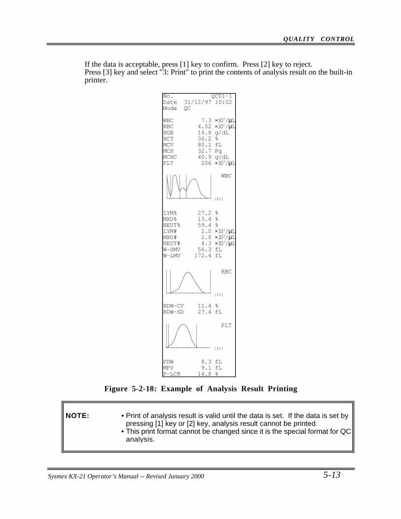
QUALITY CONTROL
Sysmex KX-21 Operator’s Manual -- Revised October 1998 5-13
If the data is acceptable, press [1] key to confirm. Press [2] key to reject.Press [3] key and select "3: Print" to print the contents of analysis result on the built-inprinter.
WBC
[fl]
RBC
[fl]
PLT
[fl]
No. QC01-1Date 31/12/97 10:02Mode QC
WBC 7.3 ×10³/µLRBC 4.52 ×10⁶/µLHGB 14.8 g/dLHCT 36.2 %MCV 80.1 fLMCH 32.7 PgMCHC 40.9 g/dLPLT 206 ×103/µL
LYM% 27.2 %MXD% 13.4 %NEUT% 59.4 %LYM# 2.0 ×10³/µLMXD# 1.0 ×10³/µLNEUT# 4.3 ×10³/µLW-SMV 56.3 fLW-LMV 172.4 fL
RDW-CV 11.4 %RDW-SD 27.4 fL
PDW 8.3 fLMPV 9.1 fLP-LCR 14.8 %
Figure 5-2-18: Example of Analysis Result Printing
NOTE: • Print of analysis result is valid until the data is set. If the data is set bypressing [1] key or [2] key, analysis result cannot be printed.
• This print format cannot be changed since it is the special format for QCanalysis.
Sysmex KX-21 Operator’s Manual -- Revised January 2000
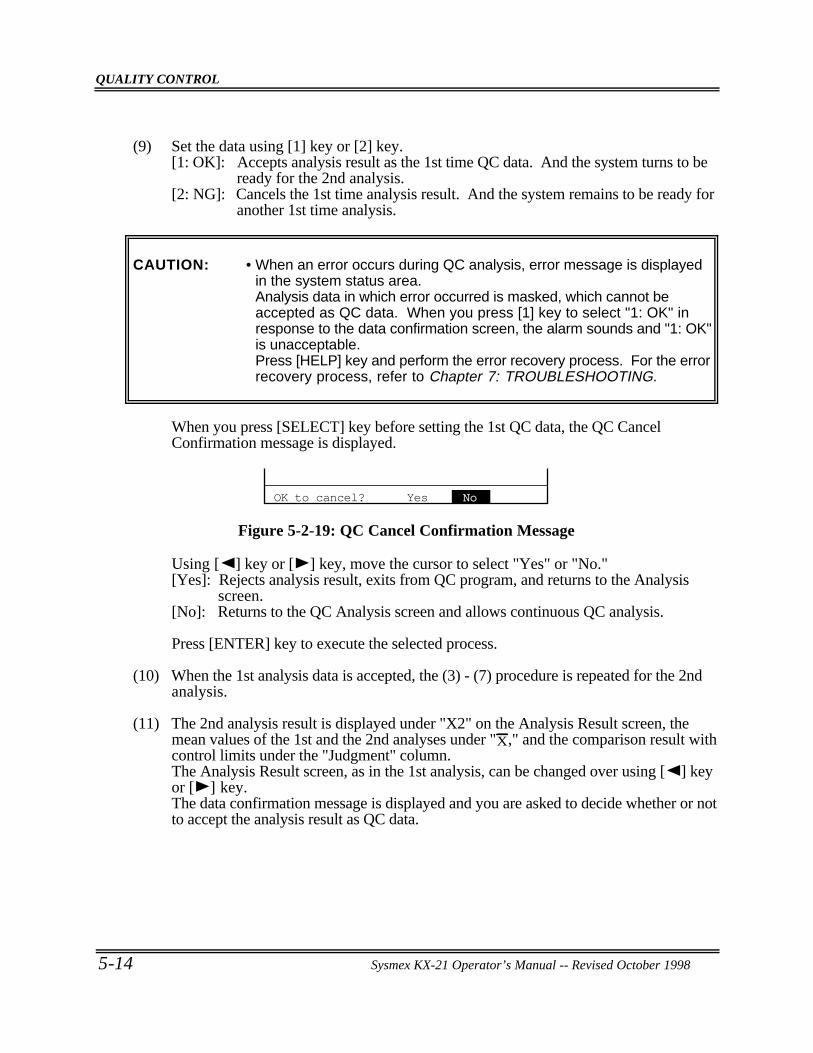
QUALITY CONTROL
5-14 Sysmex KX-21 Operator’s Manual -- Revised October 1998
(9) Set the data using [1] key or [2] key.[1: OK]: Accepts analysis result as the 1st time QC data. And the system turns to be
ready for the 2nd analysis.[2: NG]: Cancels the 1st time analysis result. And the system remains to be ready for
another 1st time analysis.
CAUTION: • When an error occurs during QC analysis, error message is displayedin the system status area.Analysis data in which error occurred is masked, which cannot beaccepted as QC data. When you press [1] key to select "1: OK" inresponse to the data confirmation screen, the alarm sounds and "1: OK"is unacceptable.Press [HELP] key and perform the error recovery process. For the errorrecovery process, refer to Chapter 7: TROUBLESHOOTING.
When you press [SELECT] key before setting the 1st QC data, the QC CancelConfirmation message is displayed.
OK to cancel? Yes No
Figure 5-2-19: QC Cancel Confirmation Message
Using [ ] key or [ ] key, move the cursor to select "Yes" or "No."[Yes]: Rejects analysis result, exits from QC program, and returns to the Analysis
screen.[No]: Returns to the QC Analysis screen and allows continuous QC analysis.
Press [ENTER] key to execute the selected process.
(10) When the 1st analysis data is accepted, the (3) - (7) procedure is repeated for the 2ndanalysis.
(11) The 2nd analysis result is displayed under "X2" on the Analysis Result screen, themean values of the 1st and the 2nd analyses under "X," and the comparison result withcontrol limits under the "Judgment" column.The Analysis Result screen, as in the 1st analysis, can be changed over using [ ] keyor [ ] key.The data confirmation message is displayed and you are asked to decide whether or notto accept the analysis result as QC data.
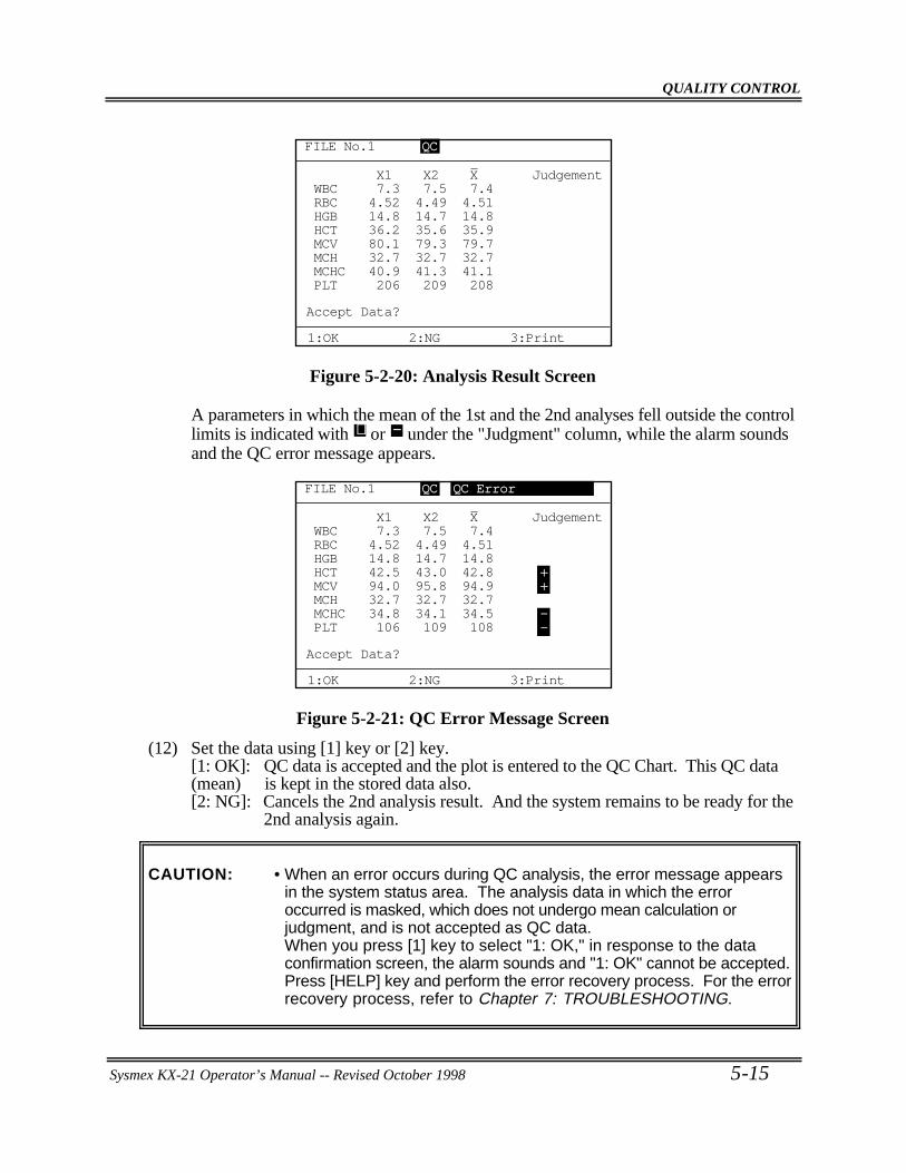
QUALITY CONTROL
Sysmex KX-21 Operator’s Manual -- Revised October 1998 5-15
Accept Data?
1:OK 2:NG 3:Print
FILE No.1 QC
X1 X2 X JudgementWBC 7.3 7.5 7.4RBC 4.52 4.49 4.51HGB 14.8 14.7 14.8HCT 36.2 35.6 35.9MCV 80.1 79.3 79.7MCH 32.7 32.7 32.7MCHC 40.9 41.3 41.1PLT 206 209 208
Figure 5-2-20: Analysis Result Screen
A parameters in which the mean of the 1st and the 2nd analyses fell outside the controllimits is indicated with + or − under the "Judgment" column, while the alarm soundsand the QC error message appears.
X1 X2 X JudgementWBC 7.3 7.5 7.4RBC 4.52 4.49 4.51HGB 14.8 14.7 14.8HCT 42.5 43.0 42.8 +MCV 94.0 95.8 94.9 +MCH 32.7 32.7 32.7 MCHC 34.8 34.1 34.5 -PLT 106 109 108 -
FILE No.1 QC QC Error
Accept Data?
1:OK 2:NG 3:Print
Figure 5-2-21: QC Error Message Screen
(12) Set the data using [1] key or [2] key.[1: OK]: QC data is accepted and the plot is entered to the QC Chart. This QC data(mean) is kept in the stored data also.[2: NG]: Cancels the 2nd analysis result. And the system remains to be ready for the
2nd analysis again.
CAUTION: • When an error occurs during QC analysis, the error message appearsin the system status area. The analysis data in which the erroroccurred is masked, which does not undergo mean calculation orjudgment, and is not accepted as QC data.When you press [1] key to select "1: OK," in response to the dataconfirmation screen, the alarm sounds and "1: OK" cannot be accepted.Press [HELP] key and perform the error recovery process. For the errorrecovery process, refer to Chapter 7: TROUBLESHOOTING.
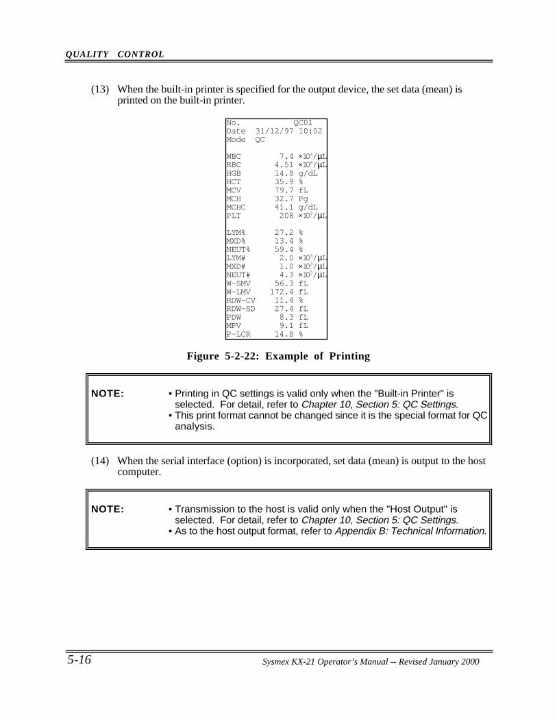
QUALITY CONTROL
5-16 Sysmex KX-21 Operator’s Manual -- Revised October 1998
(13) When the built-in printer is specified for the output device, the set data (mean) isprinted on the built-in printer.
No. QC01Date 31/12/97 10:02Mode QC
WBC 7.4 ×10³/µLRBC 4.51 ×10⁶/µLHGB 14.8 g/dLHCT 35.9 %MCV 79.7 fLMCH 32.7 PgMCHC 41.1 g/dLPLT 208 ×103/µL
LYM% 27.2 %MXD% 13.4 %NEUT% 59.4 %LYM# 2.0 ×10³/µLMXD# 1.0 ×10³/µLNEUT# 4.3 ×10³/µLW-SMV 56.3 fLW-LMV 172.4 fLRDW-CV 11.4 %RDW-SD 27.4 fLPDW 8.3 fLMPV 9.1 fLP-LCR 14.8 %
Figure 5-2-22: Example of Printing
NOTE: • Printing in QC settings is valid only when the "Built-in Printer" isselected. For detail, refer to Chapter 10, Section 5: QC Settings.
• This print format cannot be changed since it is the special format for QCanalysis.
(14) When the serial interface (option) is incorporated, set data (mean) is output to the hostcomputer.
NOTE: • Transmission to the host is valid only when the "Host Output" isselected. For detail, refer to Chapter 10, Section 5: QC Settings.
• As to the host output format, refer to Appendix B: Technical Information.
Sysmex KX-21 Operator’s Manual -- Revised January 2000
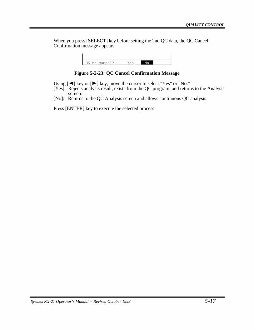
QUALITY CONTROL
Sysmex KX-21 Operator’s Manual -- Revised October 1998 5-17
When you press [SELECT] key before setting the 2nd QC data, the QC CancelConfirmation message appears.
OK to cancel? Yes No
Figure 5-2-23: QC Cancel Confirmation Message
Using [ ] key or [ ] key, move the cursor to select "Yes" or "No."[Yes]: Rejects analysis result, exists from the QC program, and returns to the Analysis
screen.[No]: Returns to the QC Analysis screen and allows continuous QC analysis.
Press [ENTER] key to execute the selected process.
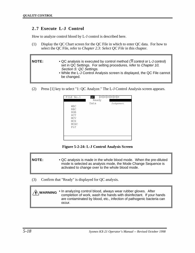
QUALITY CONTROL
5-18 Sysmex KX-21 Operator’s Manual -- Revised October 1998
2 .7 Execute L-J Control
How to analyze control blood by L-J control is described here.
(1) Display the QC Chart screen for the QC File in which to enter QC data. For how toselect the QC File, refer to Chapter 2.3: Select QC File in this chapter.
NOTE: • QC analysis is executed by control method (X control or L-J control)set in QC Settings. For setting procedures, refer to Chapter 10,Section 5: QC Settings.
• While the L-J Control Analysis screen is displayed, the QC File cannotbe changed.
(2) Press [1] key to select "1: QC Analyze." The L-J Control Analysis screen appears.
FILE No.1 QC
Data JudgementWBCRBCHGBHCTMCVMCHMCHCPLT
Ready
Figure 5-2-24: L-J Control Analysis Screen
NOTE: • QC analysis is made in the whole blood mode. When the pre-dilutedmode is selected as analysis mode, the Mode Change Sequence isactivated to change over to the whole blood mode.
(3) Confirm that "Ready" is displayed for QC analysis.
• In analyzing control blood, always wear rubber gloves. Aftercompletion of work, wash the hands with disinfectant. If your handsare contaminated by blood, etc., infection of pathogenic bacteria canoccur.
WARNING
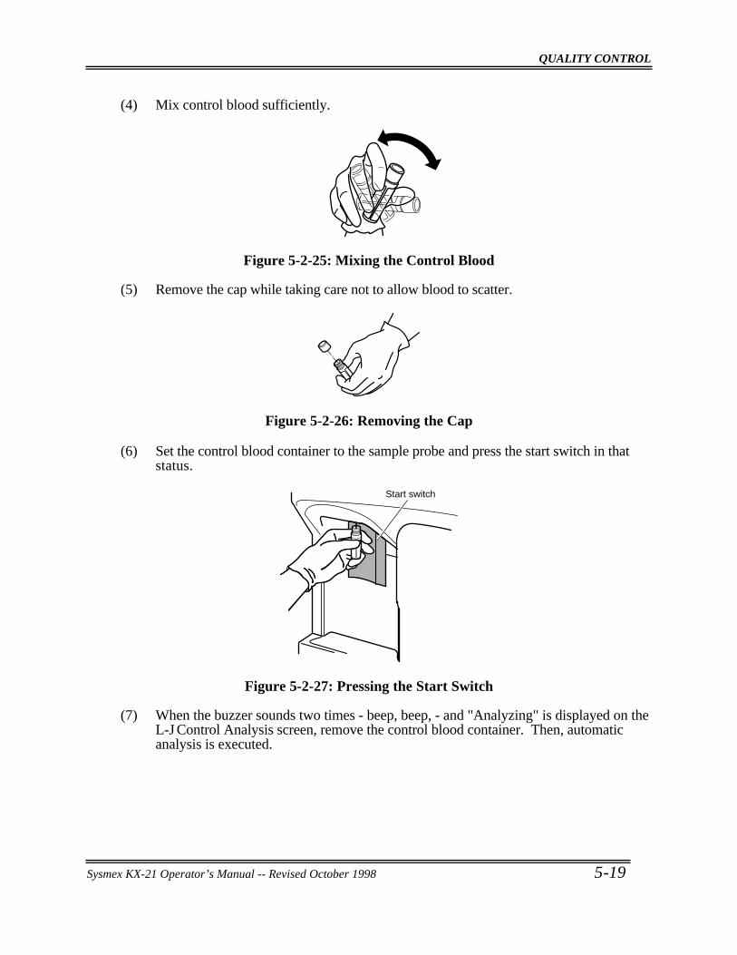
QUALITY CONTROL
Sysmex KX-21 Operator’s Manual -- Revised October 1998 5-19
(4) Mix control blood sufficiently.
Figure 5-2-25: Mixing the Control Blood
(5) Remove the cap while taking care not to allow blood to scatter.
Figure 5-2-26: Removing the Cap
(6) Set the control blood container to the sample probe and press the start switch in thatstatus.
Start switch
Figure 5-2-27: Pressing the Start Switch
(7) When the buzzer sounds two times - beep, beep, - and "Analyzing" is displayed on theL-J Control Analysis screen, remove the control blood container. Then, automaticanalysis is executed.
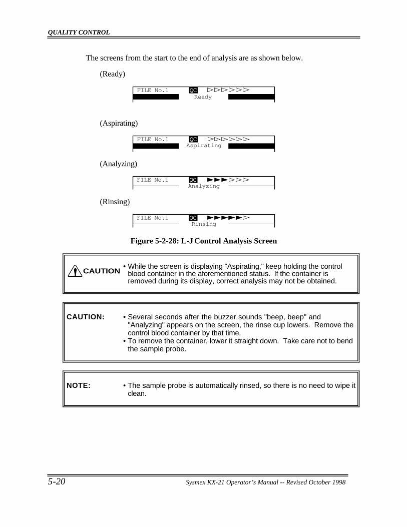
QUALITY CONTROL
5-20 Sysmex KX-21 Operator’s Manual -- Revised October 1998
The screens from the start to the end of analysis are as shown below.
(Ready)
FILE No.1 QCReady
(Aspirating)
AspiratingFILE No.1 QC
(Analyzing)
AnalyzingFILE No.1 QC
(Rinsing)
RinsingFILE No.1 QC
Figure 5-2-28: L-J Control Analysis Screen
• While the screen is displaying "Aspirating," keep holding the controlblood container in the aforementioned status. If the container isremoved during its display, correct analysis may not be obtained.
CAUTION: • Several seconds after the buzzer sounds "beep, beep" and"Analyzing" appears on the screen, the rinse cup lowers. Remove thecontrol blood container by that time.
• To remove the container, lower it straight down. Take care not to bendthe sample probe.
NOTE: • The sample probe is automatically rinsed, so there is no need to wipe itclean.
CAUTION
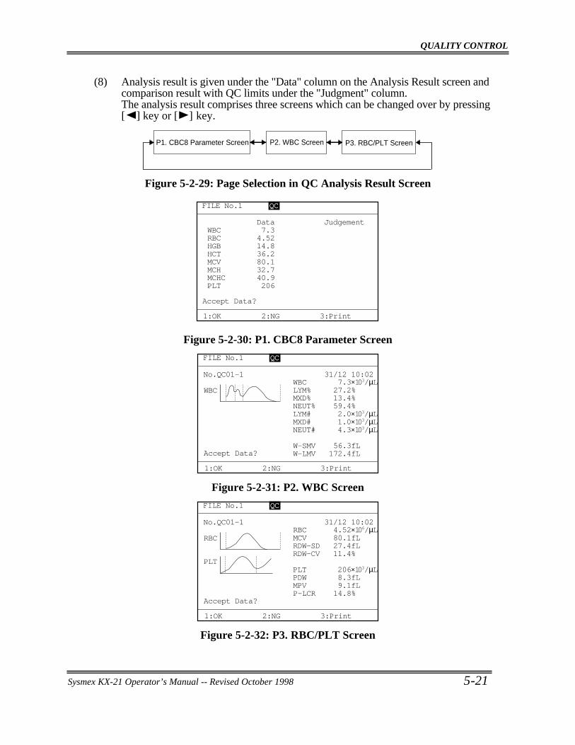
QUALITY CONTROL
Sysmex KX-21 Operator’s Manual -- Revised October 1998 5-21
(8) Analysis result is given under the "Data" column on the Analysis Result screen andcomparison result with QC limits under the "Judgment" column.The analysis result comprises three screens which can be changed over by pressing[ ] key or [ ] key.
P2. WBC Screen P3. RBC/PLT ScreenP1. CBC8 Parameter Screen
Figure 5-2-29: Page Selection in QC Analysis Result Screen
Data JudgementWBC 7.3RBC 4.52HGB 14.8HCT 36.2MCV 80.1MCH 32.7MCHC 40.9PLT 206
FILE No.1 QCQC
Accept Data?
1:OK 2:NG 3:Print
Figure 5-2-30: P1. CBC8 Parameter Screen
Accept Data?
1:OK 2:NG 3:Print
31/12 10:02No.QC01-1
W-LMV 172.4fLW-SMV 56.3fL
NEUT# 4.3×10³/µL
WBC
MXD# 1.0×10³/µLLYM# 2.0×10³/µLNEUT% 59.4%MXD% 13.4%LYM% 27.2%WBC 7.3×10³/µL
FILE No.1 QC
Figure 5-2-31: P2. WBC Screen
Accept Data?
1:OK 2:NG 3:Print
31/12 10:02No.QC01-1
P-LCR 14.8%MPV 9.1fLPDW 8.3fL
RBC
PLTPLT 206×103/µL
RDW-CV 11.4%RDW-SD 27.4fLMCV 80.1fLRBC 4.52×10⁶/µL
FILE No.1 QC
Figure 5-2-32: P3. RBC/PLT Screen
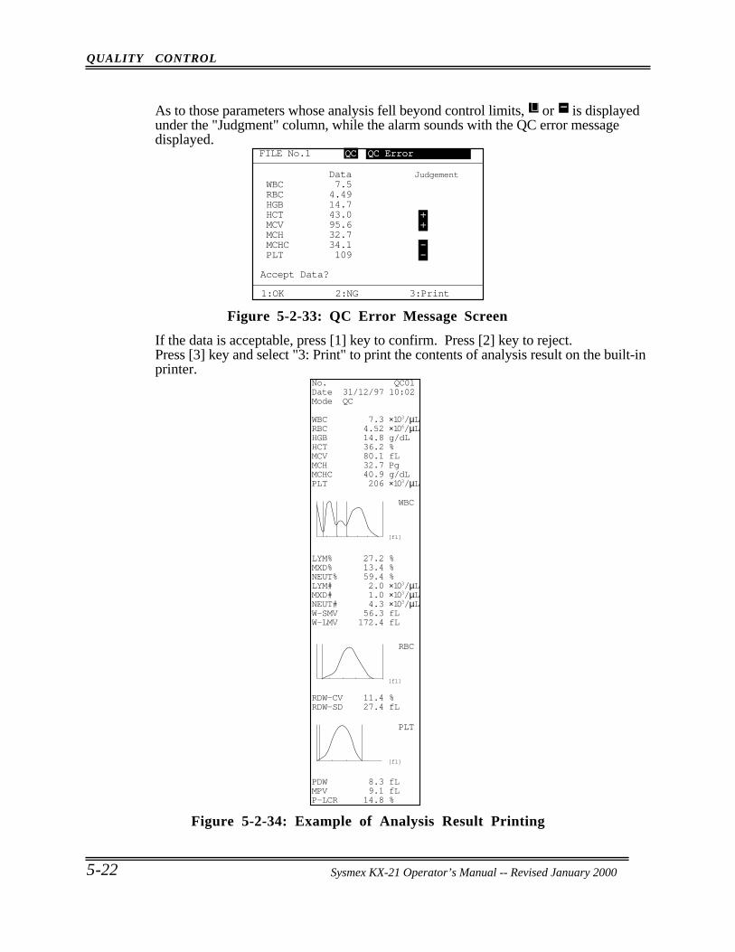
QUALITY CONTROL
5-22 Sysmex KX-21 Operator’s Manual -- Revised October 1998
As to those parameters whose analysis fell beyond control limits, + or − is displayedunder the "Judgment" column, while the alarm sounds with the QC error messagedisplayed.
Accept Data?
1:OK 2:NG 3:Print
Data JudgementWBC 7.5RBC 4.49HGB 14.7HCT 43.0 +MCV 95.6 +MCH 32.7 MCHC 34.1 -PLT 109 -
FILE No.1 QC QC Error
Figure 5-2-33: QC Error Message Screen
If the data is acceptable, press [1] key to confirm. Press [2] key to reject.Press [3] key and select "3: Print" to print the contents of analysis result on the built-inprinter.
WBC
[fl]
RBC
[fl]
PLT
[fl]
No. QC01Date 31/12/97 10:02Mode QC
WBC 7.3 ×10³/µLRBC 4.52 ×10⁶/µLHGB 14.8 g/dLHCT 36.2 %MCV 80.1 fLMCH 32.7 PgMCHC 40.9 g/dLPLT 206 ×103/µL
LYM% 27.2 %MXD% 13.4 %NEUT% 59.4 %LYM# 2.0 ×10³/µLMXD# 1.0 ×10³/µLNEUT# 4.3 ×10³/µLW-SMV 56.3 fLW-LMV 172.4 fL
RDW-CV 11.4 %RDW-SD 27.4 fL
PDW 8.3 fLMPV 9.1 fLP-LCR 14.8 %
Figure 5-2-34: Example of Analysis Result Printing
Sysmex KX-21 Operator’s Manual -- Revised January 2000
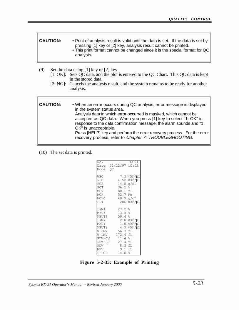
QUALITY CONTROL
Sysmex KX-21 Operator’s Manual -- Revised October 1998 5-23
CAUTION: • Print of analysis result is valid until the data is set. If the data is set bypressing [1] key or [2] key, analysis result cannot be printed.
• This print format cannot be changed since it is the special format for QCanalysis.
(9) Set the data using [1] key or [2] key.[1: OK]: Sets QC data, and the plot is entered to the QC Chart. This QC data is kept
in the stored data.[2: NG]: Cancels the analysis result, and the system remains to be ready for another
analysis.
CAUTION: • When an error occurs during QC analysis, error message is displayedin the system status area.Analysis data in which error occurred is masked, which cannot beaccepted as QC data. When you press [1] key to select "1: OK" inresponse to the data confirmation message, the alarm sounds and "1:OK" is unacceptable.Press [HELP] key and perform the error recovery process. For the errorrecovery process, refer to Chapter 7: TROUBLESHOOTING.
(10) The set data is printed.
No. QC01Date 31/12/97 10:02Mode QC
WBC 7.3 ×10³/µLRBC 4.52 ×10⁶/µLHGB 14.8 g/dLHCT 36.2 %MCV 80.1 fLMCH 32.7 PgMCHC 40.9 g/dLPLT 206 ×103/µL
LYM% 27.2 %MXD% 13.4 %NEUT% 59.4 %LYM# 2.0 ×10³/µLMXD# 1.0 ×10³/µLNEUT# 4.3 ×10³/µLW-SMV 56.3 fLW-LMV 172.4 fLRDW-CV 11.4 %RDW-SD 27.4 fLPDW 8.3 fLMPV 9.1 fLP-LCR 14.8 %
Figure 5-2-35: Example of Printing
Sysmex KX-21 Operator’s Manual -- Revised January 2000
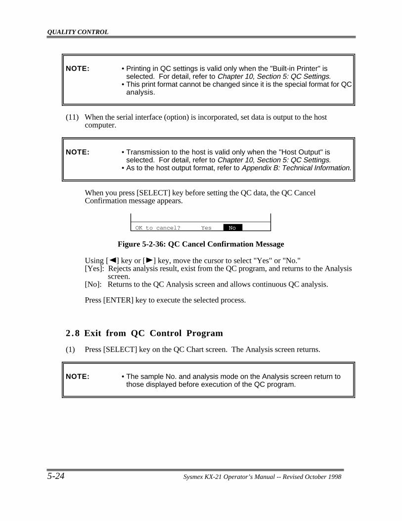
QUALITY CONTROL
5-24 Sysmex KX-21 Operator’s Manual -- Revised October 1998
NOTE: • Printing in QC settings is valid only when the "Built-in Printer" isselected. For detail, refer to Chapter 10, Section 5: QC Settings.
• This print format cannot be changed since it is the special format for QCanalysis.
(11) When the serial interface (option) is incorporated, set data is output to the hostcomputer.
NOTE: • Transmission to the host is valid only when the "Host Output" isselected. For detail, refer to Chapter 10, Section 5: QC Settings.
• As to the host output format, refer to Appendix B: Technical Information.
When you press [SELECT] key before setting the QC data, the QC CancelConfirmation message appears.
OK to cancel? Yes No
Figure 5-2-36: QC Cancel Confirmation Message
Using [ ] key or [ ] key, move the cursor to select "Yes" or "No."[Yes]: Rejects analysis result, exist from the QC program, and returns to the Analysis
screen.[No]: Returns to the QC Analysis screen and allows continuous QC analysis.
Press [ENTER] key to execute the selected process.
2 .8 Exit from QC Control Program
(1) Press [SELECT] key on the QC Chart screen. The Analysis screen returns.
NOTE: • The sample No. and analysis mode on the Analysis screen return tothose displayed before execution of the QC program.

QUALITY CONTROL
Sysmex KX-21 Operator’s Manual -- Revised October 1998 5-25
3 . DELETION
Using this menu, QC data in the line cursor position can be deleted.
How to delete QC Data(1) Display the QC Chart screen of QC file that contains the data you want to delete.
For how to select QC file, refer to Chapter 2.3: Select QC File in this chapter.
(2) Using [ ] key or [ ] key, move the line cursor to the position of the data to bedeleted.
(N=30) 31/12
ULWBC
RBC
HGB
LLUL
LLUL
LL
LIMIT DATA (MEAN) 8.1 7.6 7.3 7.1( 7.8) 4.70 4.50 4.52 4.30( 4.55) 15.5 15.0 14.8 14.5( 15.0)
FILE No.1
1:QC Analyze 2:Settings 3:Erase All
Figure 5-3-1: QC Chart Screen
(3) Press [ENTER] key.The line cursor changes from dotted line to solid line, and the menu in the MenuDisplay Area changes over to "1: Delete," "2: Print," "3: HC Output."
NOTE: • Press [ENTER] key again, and the line cursor returns to dotted line andthe menu in the Menu Display Area change to the original status.
• The line cursor that has changed to solid line cannot be moved.• "3: HC Output" on the menu is displayed only when the serial interface
(option) is incorporated.
(N=30) 31/12
ULWBC
RBC
HGB
LLUL
LLUL
LL
LIMIT DATA (MEAN) 8.1 7.6 7.3 7.1( 7.8) 4.70 4.50 4.52 4.30( 4.55) 15.5 15.0 14.8 14.5( 15.0)
FILE No.1
1:Delete 2:Print 3:HC Output
Figure 5-3-2: Deletion Menu Screen
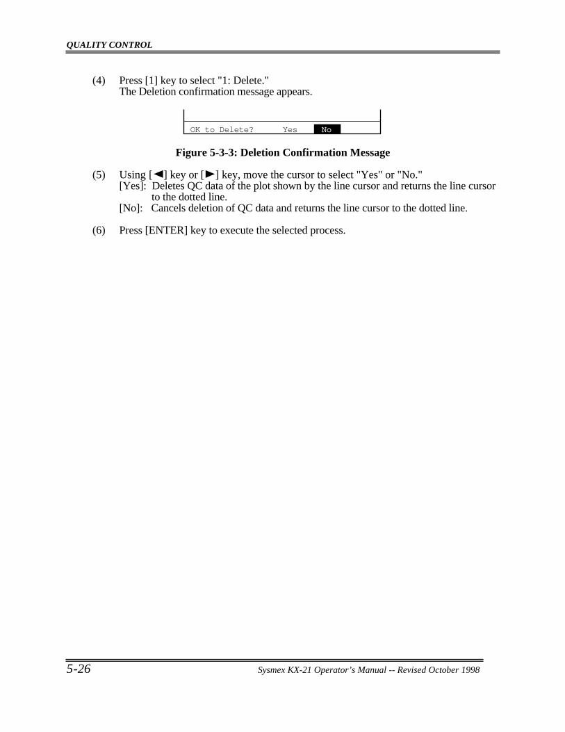
QUALITY CONTROL
5-26 Sysmex KX-21 Operator’s Manual -- Revised October 1998
(4) Press [1] key to select "1: Delete."The Deletion confirmation message appears.
OK to Delete? Yes No
Figure 5-3-3: Deletion Confirmation Message
(5) Using [ ] key or [ ] key, move the cursor to select "Yes" or "No."[Yes]: Deletes QC data of the plot shown by the line cursor and returns the line cursor
to the dotted line.[No]: Cancels deletion of QC data and returns the line cursor to the dotted line.
(6) Press [ENTER] key to execute the selected process.
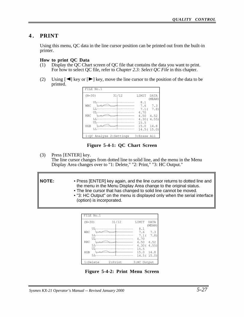
QUALITY CONTROL
Sysmex KX-21 Operator’s Manual -- Revised October 1998 5-27
4 . PRINT
Using this menu, QC data in the line cursor position can be printed out from the built-inprinter.
How to print QC Data(1) Display the QC Chart screen of QC file that contains the data you want to print.
For how to select QC file, refer to Chapter 2.3: Select QC File in this chapter.
(2) Using [ ] key or [ ] key, move the line cursor to the position of the data to beprinted.
(N=30) 31/12
ULWBC
RBC
HGB
LLUL
LLUL
LL
LIMIT DATA (MEAN) 8.1 7.6 7.3 7.1( 7.8) 4.70 4.50 4.52 4.30( 4.55) 15.5 15.0 14.8 14.5( 15.0)
FILE No.1
1:QC Analyze 2:Settings 3:Erase All
Figure 5-4-1: QC Chart Screen
(3) Press [ENTER] key.The line cursor changes from dotted line to solid line, and the menu in the MenuDisplay Area changes over to "1: Delete," "2: Print," "3: HC Output."
NOTE: • Press [ENTER] key again, and the line cursor returns to dotted line andthe menu in the Menu Display Area change to the original status.
• The line cursor that has changed to solid line cannot be moved.• "3: HC Output" on the menu is displayed only when the serial interface
(option) is incorporated.
(N=30) 31/12
ULWBC
RBC
HGB
LLUL
LLUL
LL
LIMIT DATA (MEAN) 8.1 7.6 7.3 7.1( 7.8) 4.70 4.50 4.52 4.30( 4.55) 15.5 15.0 14.8 14.5( 15.0)
FILE No.1
1:Delete 2:Print 3:HC Output
Figure 5-4-2: Print Menu Screen
Sysmex KX-21 Operator’s Manual -- Revised January 2000
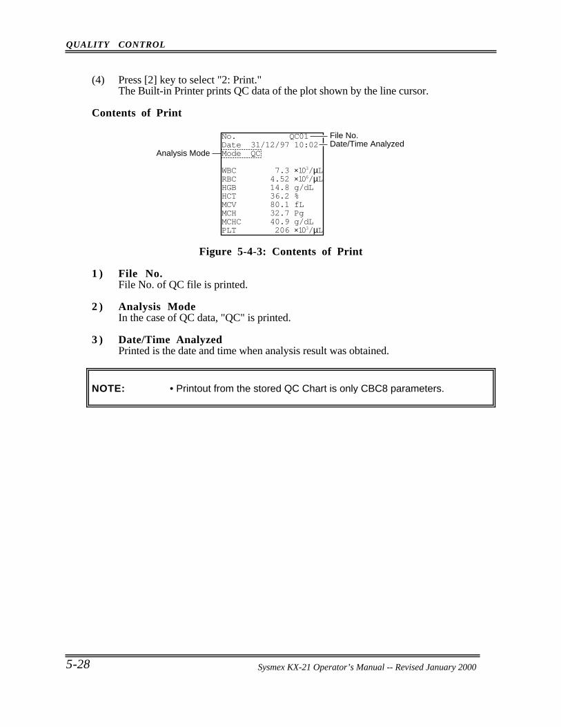
QUALITY CONTROL
5-28 Sysmex KX-21 Operator’s Manual -- Revised October 1998
(4) Press [2] key to select "2: Print."The Built-in Printer prints QC data of the plot shown by the line cursor.
Contents of Print
Analysis ModeDate/Time AnalyzedFile No.No. QC01
Date 31/12/97 10:02Mode QC
WBC 7.3 ×10³/µLRBC 4.52 ×10⁶/µLHGB 14.8 g/dLHCT 36.2 %MCV 80.1 fLMCH 32.7 PgMCHC 40.9 g/dLPLT 206 ×103/µL
Figure 5-4-3: Contents of Print
1 ) File No.File No. of QC file is printed.
2 ) Analysis ModeIn the case of QC data, "QC" is printed.
3 ) Date/Time AnalyzedPrinted is the date and time when analysis result was obtained.
NOTE: • Printout from the stored QC Chart is only CBC8 parameters.
Sysmex KX-21 Operator’s Manual -- Revised January 2000
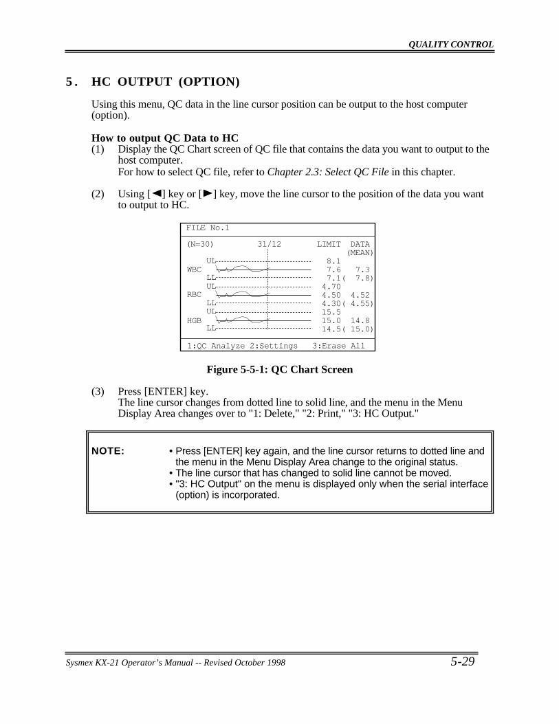
QUALITY CONTROL
Sysmex KX-21 Operator’s Manual -- Revised October 1998 5-29
5 . HC OUTPUT (OPTION)
Using this menu, QC data in the line cursor position can be output to the host computer(option).
How to output QC Data to HC(1) Display the QC Chart screen of QC file that contains the data you want to output to the
host computer.For how to select QC file, refer to Chapter 2.3: Select QC File in this chapter.
(2) Using [ ] key or [ ] key, move the line cursor to the position of the data you wantto output to HC.
(N=30) 31/12
ULWBC
RBC
HGB
LLUL
LLUL
LL
LIMIT DATA (MEAN) 8.1 7.6 7.3 7.1( 7.8) 4.70 4.50 4.52 4.30( 4.55) 15.5 15.0 14.8 14.5( 15.0)
FILE No.1
1:QC Analyze 2:Settings 3:Erase All
Figure 5-5-1: QC Chart Screen
(3) Press [ENTER] key.The line cursor changes from dotted line to solid line, and the menu in the MenuDisplay Area changes over to "1: Delete," "2: Print," "3: HC Output."
NOTE: • Press [ENTER] key again, and the line cursor returns to dotted line andthe menu in the Menu Display Area change to the original status.
• The line cursor that has changed to solid line cannot be moved.• "3: HC Output" on the menu is displayed only when the serial interface
(option) is incorporated.
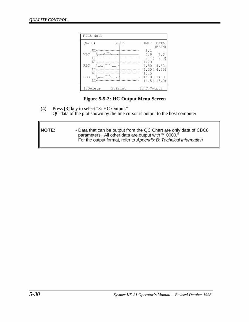
QUALITY CONTROL
5-30 Sysmex KX-21 Operator’s Manual -- Revised October 1998
(N=30) 31/12
ULWBC
RBC
HGB
LLUL
LLUL
LL
LIMIT DATA (MEAN) 8.1 7.6 7.3 7.1( 7.8) 4.70 4.50 4.52 4.30( 4.55) 15.5 15.0 14.8 14.5( 15.0)
FILE No.1
1:Delete 2:Print 3:HC Output
Figure 5-5-2: HC Output Menu Screen
(4) Press [3] key to select "3: HC Output."QC data of the plot shown by the line cursor is output to the host computer.
NOTE: • Data that can be output from the QC Chart are only data of CBC8parameters. All other data are output with "∗ 0000."For the output format, refer to Appendix B: Technical Information.
Sysmex KX-21 Operator’s Manual -- Revised October 1998
CHAPTER 6 CALIBRATION
1. INTRODUCTION ... . . . . . . . . . . . . . . . . . . . . . . . . . . . . . . . . . . . . . . . . . . . . . . . . . . . . . . . . . . . . . . 6-11.1 Calibration Execution Timing.. . . . . . . . . . . . . . . . . . . . . . . . . . . . . . . . . . . . . . . . . . . . . 6-11.2 Samples Used for Calibration .. . . . . . . . . . . . . . . . . . . . . . . . . . . . . . . . . . . . . . . . . . . . 6-11.3 Reference Values.. . . . . . . . . . . . . . . . . . . . . . . . . . . . . . . . . . . . . . . . . . . . . . . . . . . . . . . . . . . 6-11.4 Calibration Flow Chart . . . . . . . . . . . . . . . . . . . . . . . . . . . . . . . . . . . . . . . . . . . . . . . . . . . . . 6-2
2. AUTOMATIC CALIBRATION... . . . . . . . . . . . . . . . . . . . . . . . . . . . . . . . . . . . . . . . . . . . . . . . 6-32.1 Executing Automatic Calibration Program ... . . . . . . . . . . . . . . . . . . . . . . . . . . . . 6-32.2 Automatic Calibration Procedure.. . . . . . . . . . . . . . . . . . . . . . . . . . . . . . . . . . . . . . . . . 6-4
3. MANUAL CALIBRATION ... . . . . . . . . . . . . . . . . . . . . . . . . . . . . . . . . . . . . . . . . . . . . . . . . . . . 6-93.1 Calculating Calibration Value.. . . . . . . . . . . . . . . . . . . . . . . . . . . . . . . . . . . . . . . . . . . . . 6-93.2 Manual Calibration Procedure .. . . . . . . . . . . . . . . . . . . . . . . . . . . . . . . . . . . . . . . . . . .6-10
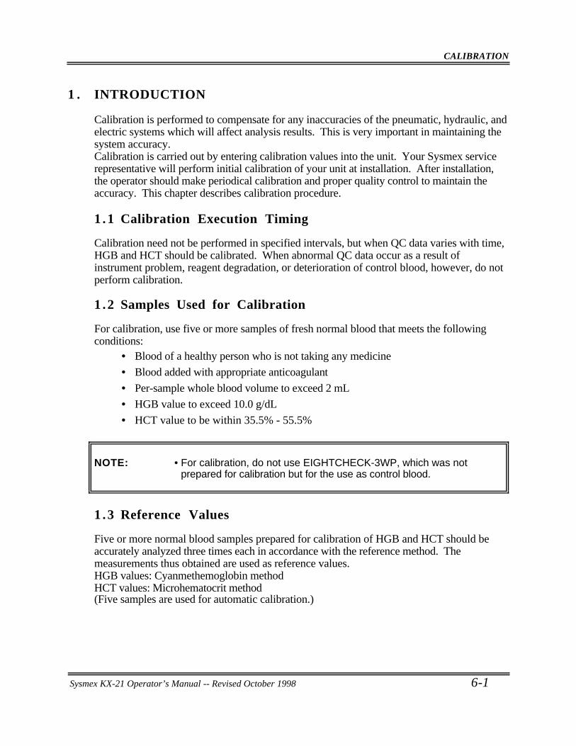
CALIBRATION
Sysmex KX-21 Operator’s Manual -- Revised October 1998 6-1
1 . INTRODUCTION
Calibration is performed to compensate for any inaccuracies of the pneumatic, hydraulic, andelectric systems which will affect analysis results. This is very important in maintaining thesystem accuracy.Calibration is carried out by entering calibration values into the unit. Your Sysmex servicerepresentative will perform initial calibration of your unit at installation. After installation,the operator should make periodical calibration and proper quality control to maintain theaccuracy. This chapter describes calibration procedure.
1 .1 Calibration Execution Timing
Calibration need not be performed in specified intervals, but when QC data varies with time,HGB and HCT should be calibrated. When abnormal QC data occur as a result ofinstrument problem, reagent degradation, or deterioration of control blood, however, do notperform calibration.
1 .2 Samples Used for Calibration
For calibration, use five or more samples of fresh normal blood that meets the followingconditions:
• Blood of a healthy person who is not taking any medicine
• Blood added with appropriate anticoagulant
• Per-sample whole blood volume to exceed 2 mL
• HGB value to exceed 10.0 g/dL
• HCT value to be within 35.5% - 55.5%
NOTE: • For calibration, do not use EIGHTCHECK-3WP, which was notprepared for calibration but for the use as control blood.
1 .3 Reference Values
Five or more normal blood samples prepared for calibration of HGB and HCT should beaccurately analyzed three times each in accordance with the reference method. Themeasurements thus obtained are used as reference values.HGB values: Cyanmethemoglobin methodHCT values: Microhematocrit method(Five samples are used for automatic calibration.)
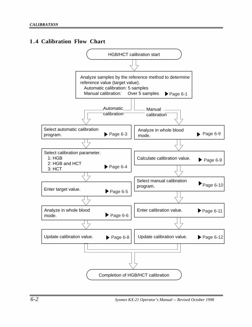
CALIBRATION
6-2 Sysmex KX-21 Operator’s Manual -- Revised October 1998
1 .4 Calibration Flow Chart
HGB/HCT calibration start
Completion of HGB/HCT calibration
Analyze samples by the reference method to determine reference value (target value). Automatic calibration: 5 samples Manual calibration: Over 5 samples
Analyze in whole blood mode.
Calculate calibration value.
Select manual calibration program.
Enter calibration value.
Update calibration value.
Select automatic calibration program.
Enter target value.
Analyze in whole blood mode.
Update calibration value.
Select calibration parameter. 1: HGB 2: HGB and HCT 3: HCT
Page 6-1
Page 6-11
Page 6-12
Page 6-10
Page 6-9
Page 6-9Page 6-3
Page 6-4
Page 6-5
Page 6-8
Page 6-6
Automatic calibration
Manual calibration
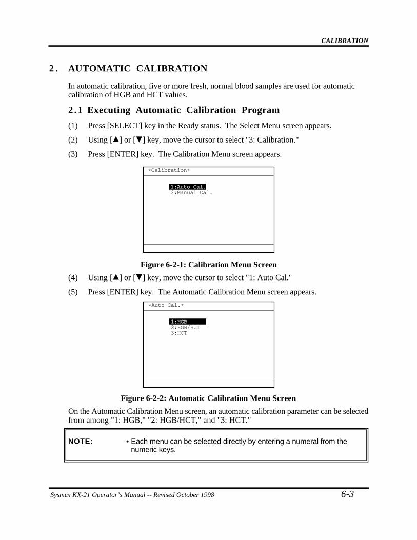
CALIBRATION
Sysmex KX-21 Operator’s Manual -- Revised October 1998 6-3
2 . AUTOMATIC CALIBRATION
In automatic calibration, five or more fresh, normal blood samples are used for automaticcalibration of HGB and HCT values.
2 .1 Executing Automatic Calibration Program
(1) Press [SELECT] key in the Ready status. The Select Menu screen appears.
(2) Using [ ] or [ ] key, move the cursor to select "3: Calibration."
(3) Press [ENTER] key. The Calibration Menu screen appears.
*Calibration*
1:Auto Cal.2:Manual Cal.
Figure 6-2-1: Calibration Menu Screen
(4) Using [ ] or [ ] key, move the cursor to select "1: Auto Cal."
(5) Press [ENTER] key. The Automatic Calibration Menu screen appears.
*Auto Cal.*
1:HGB2:HGB/HCT3:HCT
Figure 6-2-2: Automatic Calibration Menu Screen
On the Automatic Calibration Menu screen, an automatic calibration parameter can be selectedfrom among "1: HGB," "2: HGB/HCT," and "3: HCT."
NOTE: • Each menu can be selected directly by entering a numeral from thenumeric keys.
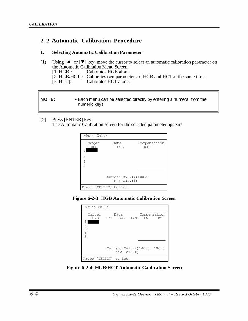
CALIBRATION
6-4 Sysmex KX-21 Operator’s Manual -- Revised October 1998
2 .2 Automatic Calibration Procedure
1. Selecting Automatic Calibration Parameter
(1) Using [ ] or [ ] key, move the cursor to select an automatic calibration parameter onthe Automatic Calibration Menu Screen:[1: HGB]: Calibrates HGB alone.[2: HGB/HCT]: Calibrates two parameters of HGB and HCT at the same time.[3: HCT]: Calibrates HCT alone.
NOTE: • Each menu can be selected directly by entering a numeral from thenumeric keys.
(2) Press [ENTER] key.The Automatic Calibration screen for the selected parameter appears.
Target HGB
12345
Data HGB
Compensation HGB
Current Cal.(%)100.0 New Cal.(%)
*Auto Cal.*
Press [SELECT] to Set.
Figure 6-2-3: HGB Automatic Calibration Screen
Target HGB HCT HCT HCT
12345
Data HGB
Compensation HGB
Current Cal.(%)100.0 100.0 New Cal.(%)
*Auto Cal.*
Press [SELECT] to Set.
Figure 6-2-4: HGB/HCT Automatic Calibration Screen
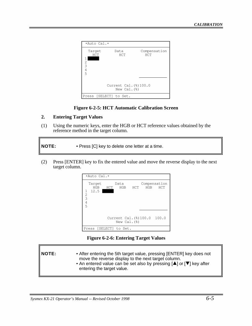
CALIBRATION
Sysmex KX-21 Operator’s Manual -- Revised October 1998 6-5
Target HCT
Current Cal.(%)100.0 New Cal.(%)
12345
Data HCT
Compensation HCT
*Auto Cal.*
Press [SELECT] to Set.
Figure 6-2-5: HCT Automatic Calibration Screen
2. Entering Target Values
(1) Using the numeric keys, enter the HGB or HCT reference values obtained by thereference method in the target column.
NOTE: • Press [C] key to delete one letter at a time.
(2) Press [ENTER] key to fix the entered value and move the reverse display to the nexttarget column.
Target HGB 12.5
HCT HCT HCT
Current Cal.(%)100.0 100.0 New Cal.(%)
12345
Data HGB
Compensation HGB
*Auto Cal.*
Press [SELECT] to Set.
Figure 6-2-6: Entering Target Values
NOTE: • After entering the 5th target value, pressing [ENTER] key does notmove the reverse display to the next target column.
• An entered value can be set also by pressing [ ] or [ ] key afterentering the target value.
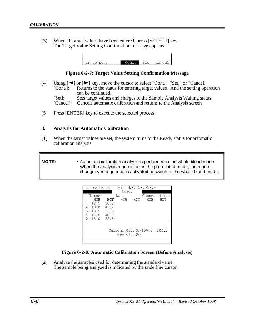
CALIBRATION
6-6 Sysmex KX-21 Operator’s Manual -- Revised October 1998
(3) When all target values have been entered, press [SELECT] key.The Target Value Setting Confirmation message appears.
OK to set? Cont. Set Cancel
Figure 6-2-7: Target Value Setting Confirmation Message
(4) Using [ ] or [ ] key, move the cursor to select "Cont.," "Set," or "Cancel."[Cont.]: Returns to the status for entering target values. And the setting operation
can be continued.[Set]: Sets target values and charges to the Sample Analysis Waiting status.[Cancel]: Cancels automatic calibration and returns to the Analysis screen.
(5) Press [ENTER] key to execute the selected process.
3. Analysis for Automatic Calibration
(1) When the target values are set, the system turns to the Ready status for automaticcalibration analysis.
NOTE: • Automatic calibration analysis is performed in the whole blood mode.When the analysis mode is set in the pre-diluted mode, the modechangeover sequence is activated to switch to the whole blood mode.
Target HGB 12.5 13.0 13.5 11.0 15.0
HCT50.045.251.540.852.5
HCT
*Auto Cal.* WBReady
HCT HCT12345
Data HGB
Compensation HGB
Current Cal.(%)100.0 100.0 New Cal.(%)
Figure 6-2-8: Automatic Calibration Screen (Before Analysis)
(2) Analyze the samples used for determining the standard value.The sample being analyzed is indicated by the underline cursor.
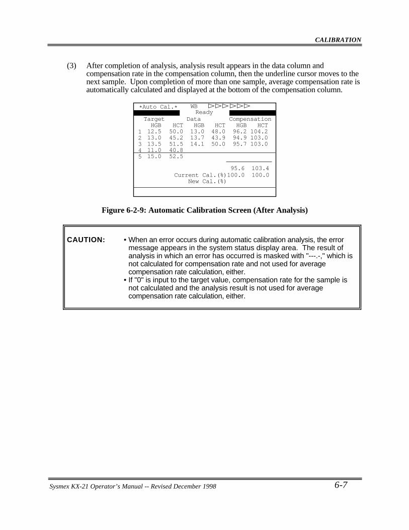
CALIBRATION
Sysmex KX-21 Operator’s Manual -- Revised October 1998 6-7
(3) After completion of analysis, analysis result appears in the data column andcompensation rate in the compensation column, then the underline cursor moves to thenext sample. Upon completion of more than one sample, average compensation rate isautomatically calculated and displayed at the bottom of the compensation column.
Target HGB 12.5 13.0 13.5 11.0 15.0
HCT50.045.251.540.852.5
HCT48.043.950.0
95.6 103.4
HCT104.2103.0103.0
12345
Data HGB 13.0 13.7 14.1
Compensation HGB 96.2 94.9 95.7
WB*Auto Cal.*Ready
Current Cal.(%)100.0 100.0 New Cal.(%)
Figure 6-2-9: Automatic Calibration Screen (After Analysis)
CAUTION: • When an error occurs during automatic calibration analysis, the errormessage appears in the system status display area. The result ofanalysis in which an error has occurred is masked with "---.-," which isnot calculated for compensation rate and not used for averagecompensation rate calculation, either.
• If "0" is input to the target value, compensation rate for the sample isnot calculated and the analysis result is not used for averagecompensation rate calculation, either.
Sysmex KX-21 Operator’s Manual -- Revised December 1998
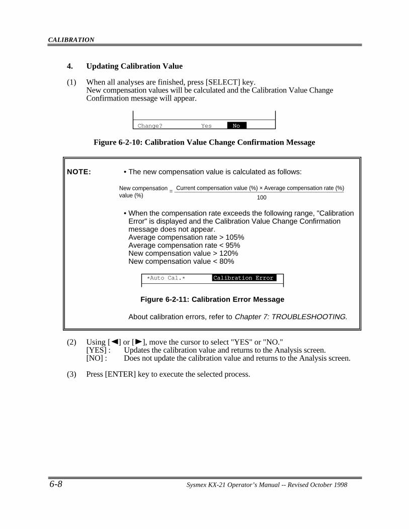
CALIBRATION
6-8 Sysmex KX-21 Operator’s Manual -- Revised October 1998
4. Updating Calibration Value
(1) When all analyses are finished, press [SELECT] key.New compensation values will be calculated and the Calibration Value ChangeConfirmation message will appear.
Change? Yes No
Figure 6-2-10: Calibration Value Change Confirmation Message
NOTE: • The new compensation value is calculated as follows:
New compensation value (%)
Current compensation value (%) × Average compensation rate (%)
100=
• When the compensation rate exceeds the following range, "CalibrationError" is displayed and the Calibration Value Change Confirmationmessage does not appear.Average compensation rate > 105%Average compensation rate < 95%New compensation value > 120%New compensation value < 80%
*Auto Cal.* Calibration Error
Figure 6-2-11: Calibration Error Message
About calibration errors, refer to Chapter 7: TROUBLESHOOTING.
(2) Using [ ] or [ ], move the cursor to select "YES" or "NO."[YES] : Updates the calibration value and returns to the Analysis screen.[NO] : Does not update the calibration value and returns to the Analysis screen.
(3) Press [ENTER] key to execute the selected process.

CALIBRATION
Sysmex KX-21 Operator’s Manual -- Revised October 1998 6-9
3 . MANUAL CALIBRATION
In manual calibration, calculated calibration value can be entered using the numeric keys.
3 .1 Calculating Calibration Value
(1) Analyze more than five samples, each three times, by the reference method and averageHGB and HCT values.
(2) Gently mix the same samples sufficiently and analyze them in the whole blood mode.
(3) When there is a difference between data gained by analysis with this instrument and thereference value gained by the reference method, use the following formula to calculatethe new calibration value:
= ×
[Example]Average of HGB values gained by the reference method = 15.6 g/dLAverage of HGB values gained by this instrument = 15.5 g/dLPrevious calibration value of HGB = 100.0%
100.0 × = 100.65 = 100.7%15.615.5
. .
Therefore, the new calibration value of HGB needs to be set at 100.7%. This meansthat the calibration value increased 0.7%.
New calibrationvalue
Previouscalibration value
Average of values gainedby reference method
Average of values gainedby this instrument
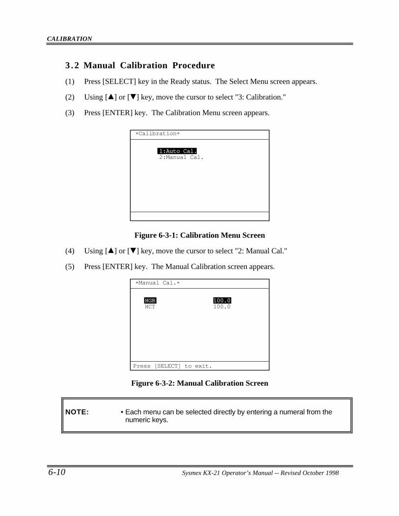
CALIBRATION
6-10 Sysmex KX-21 Operator’s Manual -- Revised October 1998
3 .2 Manual Calibration Procedure
(1) Press [SELECT] key in the Ready status. The Select Menu screen appears.
(2) Using [ ] or [ ] key, move the cursor to select "3: Calibration."
(3) Press [ENTER] key. The Calibration Menu screen appears.
*Calibration*
1:Auto Cal.2:Manual Cal.
Figure 6-3-1: Calibration Menu Screen
(4) Using [ ] or [ ] key, move the cursor to select "2: Manual Cal."
(5) Press [ENTER] key. The Manual Calibration screen appears.
HGBHCT
100.0100.0
*Manual Cal.*
Press [SELECT] to exit.
Figure 6-3-2: Manual Calibration Screen
NOTE: • Each menu can be selected directly by entering a numeral from thenumeric keys.
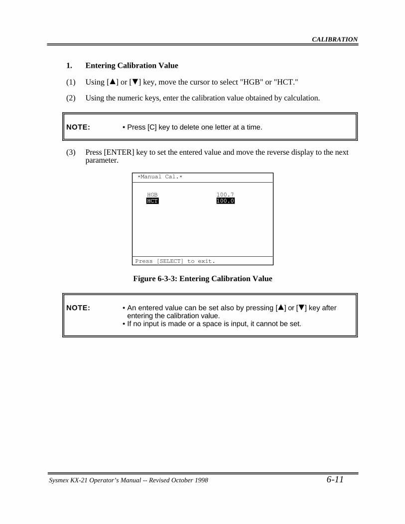
CALIBRATION
Sysmex KX-21 Operator’s Manual -- Revised October 1998 6-11
1. Entering Calibration Value
(1) Using [ ] or [ ] key, move the cursor to select "HGB" or "HCT."
(2) Using the numeric keys, enter the calibration value obtained by calculation.
NOTE: • Press [C] key to delete one letter at a time.
(3) Press [ENTER] key to set the entered value and move the reverse display to the nextparameter.
HGBHCT
100.7100.0
*Manual Cal.*
Press [SELECT] to exit.
Figure 6-3-3: Entering Calibration Value
NOTE: • An entered value can be set also by pressing [ ] or [ ] key afterentering the calibration value.
• If no input is made or a space is input, it cannot be set.
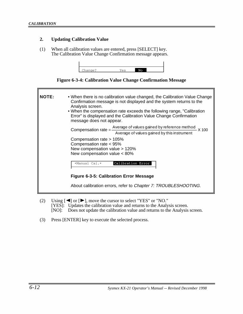
CALIBRATION
6-12 Sysmex KX-21 Operator’s Manual -- Revised October 1998
2. Updating Calibration Value
(1) When all calibration values are entered, press [SELECT] key.The Calibration Value Change Confirmation message appears.
Change? Yes No
Figure 6-3-4: Calibration Value Change Confirmation Message
NOTE: • When there is no calibration value changed, the Calibration Value ChangeConfirmation message is not displayed and the system returns to theAnalysis screen.
• When the compensation rate exceeds the following range, "CalibrationError" is displayed and the Calibration Value Change Confirmationmessage does not appear.
Compensation rate = Average of values gained by reference method
Average of values gained by this instrument
X 100
Compensation rate > 105%Compensation rate < 95%New compensation value > 120%New compensation value < 80%
*Manual Cal.* Calibration Error
Figure 6-3-5: Calibration Error Message
About calibration errors, refer to Chapter 7: TROUBLESHOOTING.
(2) Using [ ] or [ ], move the cursor to select "YES" or "NO."[YES]: Updates the calibration value and returns to the Analysis screen.[NO]: Does not update the calibration value and returns to the Analysis screen.
(3) Press [ENTER] key to execute the selected process.
Sysmex KX-21 Operator’s Manual -- Revised December 1998
Sysmex KX-21 Operator’s Manual -- Revised January 2000
CHAPTER 7 TROUBLESHOOTING
1. INTRODUCTION... . . . . . . . . . . . . . . . . . . . . . . . . . . . . . . . . . . . . . . . . . . . . . . . . . . . . . . . . . . . . . . 7-1
2. WHEN YOU SUSPECT A TROUBLE ... . . . . . . . . . . . . . . . . . . . . . . . . . . . . . . . . . . . . . 7-22.1 Alphabetical List of Error Messages
Displayed on Analysis Screen .. . . . . . . . . . . . . . . . . . . . . . . . . . . . . . . . . . . . . . . . . . . 7-32.2 Alphabetical List of Error Messages Displayed on HELP Screen .. . . 7-42.3 Functional List of Error Messages .. . . . . . . . . . . . . . . . . . . . . . . . . . . . . . . . . . . . . . 7-5
3. TROUBLESHOOTING GUIDE ... . . . . . . . . . . . . . . . . . . . . . . . . . . . . . . . . . . . . . . . . . . . . . 7-73.1 Pressure/Vacuum Errors.. . . . . . . . . . . . . . . . . . . . . . . . . . . . . . . . . . . . . . . . . . . . . . . . . . 7-73.2 Chamber Errors.. . . . . . . . . . . . . . . . . . . . . . . . . . . . . . . . . . . . . . . . . . . . . . . . . . . . . . . . . . 7-103.3 Motor Errors .. . . . . . . . . . . . . . . . . . . . . . . . . . . . . . . . . . . . . . . . . . . . . . . . . . . . . . . . . . . . . 7-133.4 Transducer Errors .. . . . . . . . . . . . . . . . . . . . . . . . . . . . . . . . . . . . . . . . . . . . . . . . . . . . . . . 7-153.5 Temperature Errors.. . . . . . . . . . . . . . . . . . . . . . . . . . . . . . . . . . . . . . . . . . . . . . . . . . . . . . 7-163.6 Analysis Errors .. . . . . . . . . . . . . . . . . . . . . . . . . . . . . . . . . . . . . . . . . . . . . . . . . . . . . . . . . . 7-173.7 Memory Errors .. . . . . . . . . . . . . . . . . . . . . . . . . . . . . . . . . . . . . . . . . . . . . . . . . . . . . . . . . . 7-233.8 Others.. . . . . . . . . . . . . . . . . . . . . . . . . . . . . . . . . . . . . . . . . . . . . . . . . . . . . . . . . . . . . . . . . . . . . 7-253.9 Maintenance Errors.. . . . . . . . . . . . . . . . . . . . . . . . . . . . . . . . . . . . . . . . . . . . . . . . . . . . . . 7-273.10 Built-in Printer Errors.. . . . . . . . . . . . . . . . . . . . . . . . . . . . . . . . . . . . . . . . . . . . . . . . . . . 7-303.11 External Device Errors (When this option is incorporated).. . . . . . . . . 7-33
4. STATUS DISPLAY... . . . . . . . . . . . . . . . . . . . . . . . . . . . . . . . . . . . . . . . . . . . . . . . . . . . . . . . . . . 7-34
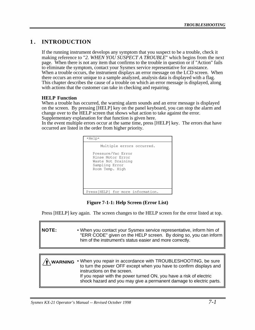
TROUBLESHOOTING
Sysmex KX-21 Operator’s Manual -- Revised October 1998 7-1
1 . INTRODUCTION
If the running instrument develops any symptom that you suspect to be a trouble, check itmaking reference to "2. WHEN YOU SUSPECT A TROUBLE" which begins from the nextpage. When there is not any item that confirms to the trouble in question or if "Action" failsto eliminate the symptom, contact your Sysmex service representative for assistance.When a trouble occurs, the instrument displays an error message on the LCD screen. Whenthere occurs an error unique to a sample analyzed, analysis data is displayed with a flag.This chapter describes the cause of a trouble on which an error message is displayed, alongwith actions that the customer can take in checking and repairing.
HELP FunctionWhen a trouble has occurred, the warning alarm sounds and an error message is displayedon the screen. By pressing [HELP] key on the panel keyboard, you can stop the alarm andchange over to the HELP screen that shows what action to take against the error.Supplementary explanation for that function is given here.In the event multiple errors occur at the same time, press [HELP] key. The errors that haveoccurred are listed in the order from higher priority.
*Help*
Multiple errors occurred.
Pressure/Vac ErrorRinse Motor ErrorWaste Not DrainingSampling ErrorRoom Temp. High
Press[HELP] for more information.
Figure 7-1-1: Help Screen (Error List)
Press [HELP] key again. The screen changes to the HELP screen for the error listed at top.
NOTE: • When you contact your Sysmex service representative, inform him of"ERR CODE" given on the HELP screen. By doing so, you can informhim of the instrument's status easier and more correctly.
• When you repair in accordance with TROUBLESHOOTING, be sureto turn the power OFF except when you have to confirm displays andinstructions on the screen.If you repair with the power turned ON, you have a risk of electricshock hazard and you may give a permanent damage to electric parts.
WARNING
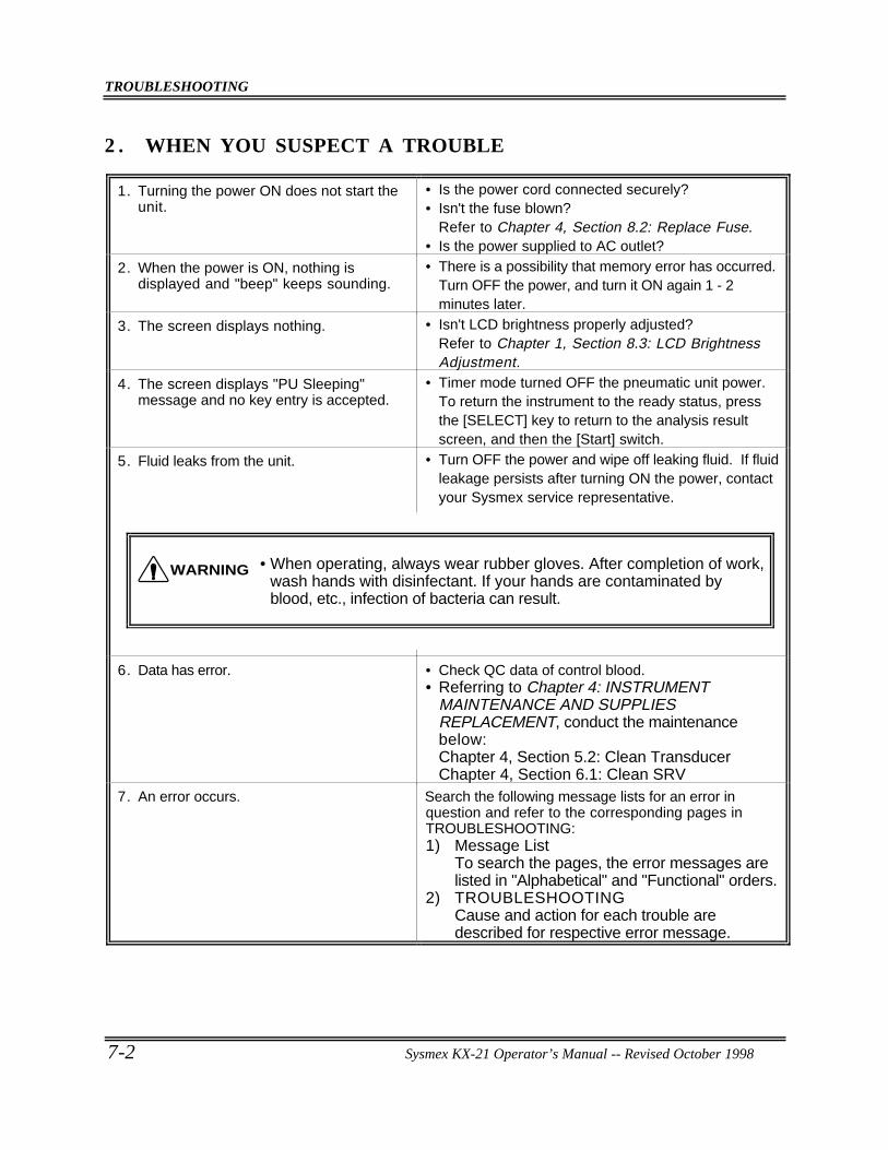
TROUBLESHOOTING
7-2 Sysmex KX-21 Operator’s Manual -- Revised October 1998
2 . WHEN YOU SUSPECT A TROUBLE
1. Turning the power ON does not start theunit.
• Is the power cord connected securely?• Isn't the fuse blown?
Refer to Chapter 4, Section 8.2: Replace Fuse.• Is the power supplied to AC outlet?
2. When the power is ON, nothing isdisplayed and "beep" keeps sounding.
• There is a possibility that memory error has occurred.Turn OFF the power, and turn it ON again 1 - 2minutes later.
3. The screen displays nothing. • Isn't LCD brightness properly adjusted?Refer to Chapter 1, Section 8.3: LCD BrightnessAdjustment.
4. The screen displays "PU Sleeping"message and no key entry is accepted.
• Timer mode turned OFF the pneumatic unit power.To return the instrument to the ready status, pressthe [SELECT] key to return to the analysis resultscreen, and then the [Start] switch.
5. Fluid leaks from the unit. • Turn OFF the power and wipe off leaking fluid. If fluidleakage persists after turning ON the power, contactyour Sysmex service representative.
6. Data has error. • Check QC data of control blood.• Referring to Chapter 4: INSTRUMENT
MAINTENANCE AND SUPPLIESREPLACEMENT, conduct the maintenancebelow:Chapter 4, Section 5.2: Clean TransducerChapter 4, Section 6.1: Clean SRV
7. An error occurs. Search the following message lists for an error inquestion and refer to the corresponding pages inTROUBLESHOOTING:1) Message List
To search the pages, the error messages arelisted in "Alphabetical" and "Functional" orders.
2) TROUBLESHOOTINGCause and action for each trouble aredescribed for respective error message.
• When operating, always wear rubber gloves. After completion of work,wash hands with disinfectant. If your hands are contaminated byblood, etc., infection of bacteria can result.
WARNING
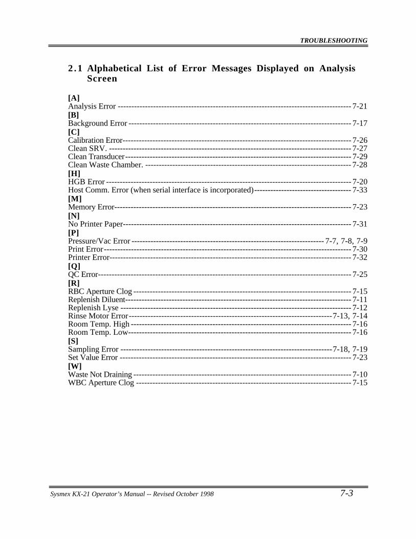
TROUBLESHOOTING
Sysmex KX-21 Operator’s Manual -- Revised October 1998 7-3
2 . 1 Alphabetical List of Error Messages Displayed on AnalysisScreen
[A]Analysis Error -------------------------------------------------------------------------------------- 7-21[B]Background Error ---------------------------------------------------------------------------------- 7-17[C]Calibration Error------------------------------------------------------------------------------------ 7-26Clean SRV. ----------------------------------------------------------------------------------------- 7-27Clean Transducer----------------------------------------------------------------------------------- 7-29Clean Waste Chamber. ---------------------------------------------------------------------------- 7-28[H]HGB Error ------------------------------------------------------------------------------------------ 7-20Host Comm. Error (when serial interface is incorporated)------------------------------------ 7-33[M]Memory Error--------------------------------------------------------------------------------------- 7-23[N]No Printer Paper------------------------------------------------------------------------------------ 7-31[P]Pressure/Vac Error ----------------------------------------------------------------------- 7-7, 7-8, 7-9Print Error------------------------------------------------------------------------------------------- 7-30Printer Error----------------------------------------------------------------------------------------- 7-32[Q]QC Error--------------------------------------------------------------------------------------------- 7-25[R]RBC Aperture Clog -------------------------------------------------------------------------------- 7-15Replenish Diluent----------------------------------------------------------------------------------- 7-11Replenish Lyse ------------------------------------------------------------------------------------- 7-12Rinse Motor Error---------------------------------------------------------------------------7-13, 7-14Room Temp. High --------------------------------------------------------------------------------- 7-16Room Temp. Low---------------------------------------------------------------------------------- 7-16[S]Sampling Error ------------------------------------------------------------------------------7-18, 7-19Set Value Error ------------------------------------------------------------------------------------- 7-23[W]Waste Not Draining -------------------------------------------------------------------------------- 7-10WBC Aperture Clog ------------------------------------------------------------------------------- 7-15
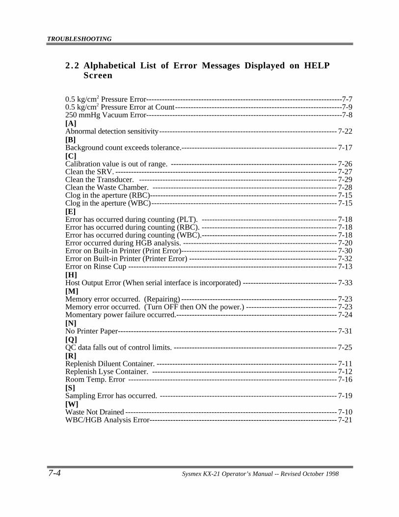
TROUBLESHOOTING
7-4 Sysmex KX-21 Operator’s Manual -- Revised October 1998
2 .2 Alphabetical List of Error Messages Displayed on HELPScreen
0.5 kg/cm2 Pressure Error---------------------------------------------------------------------------7-70.5 kg/cm2 Pressure Error at Count----------------------------------------------------------------7-9250 mmHg Vacuum Error---------------------------------------------------------------------------7-8[A]Abnormal detection sensitivity-------------------------------------------------------------------- 7-22[B]Background count exceeds tolerance.------------------------------------------------------------ 7-17[C]Calibration value is out of range. ---------------------------------------------------------------- 7-26Clean the SRV. ------------------------------------------------------------------------------------- 7-27Clean the Transducer. ---------------------------------------------------------------------------- 7-29Clean the Waste Chamber. ----------------------------------------------------------------------- 7-28Clog in the aperture (RBC)------------------------------------------------------------------------ 7-15Clog in the aperture (WBC)----------------------------------------------------------------------- 7-15[E]Error has occurred during counting (PLT). ---------------------------------------------------- 7-18Error has occurred during counting (RBC). ---------------------------------------------------- 7-18Error has occurred during counting (WBC).---------------------------------------------------- 7-18Error occurred during HGB analysis. ----------------------------------------------------------- 7-20Error on Built-in Printer (Print Error)------------------------------------------------------------ 7-30Error on Built-in Printer (Printer Error) --------------------------------------------------------- 7-32Error on Rinse Cup -------------------------------------------------------------------------------- 7-13[H]Host Output Error (When serial interface is incorporated) ------------------------------------ 7-33[M]Memory error occurred. (Repairing) ------------------------------------------------------------ 7-23Memory error occurred. (Turn OFF then ON the power.) ----------------------------------- 7-23Momentary power failure occurred.-------------------------------------------------------------- 7-24[N]No Printer Paper------------------------------------------------------------------------------------ 7-31[Q]QC data falls out of control limits. --------------------------------------------------------------- 7-25[R]Replenish Diluent Container. --------------------------------------------------------------------- 7-11Replenish Lyse Container. ----------------------------------------------------------------------- 7-12Room Temp. Error -------------------------------------------------------------------------------- 7-16[S]Sampling Error has occurred. -------------------------------------------------------------------- 7-19[W]Waste Not Drained --------------------------------------------------------------------------------- 7-10WBC/HGB Analysis Error------------------------------------------------------------------------ 7-21
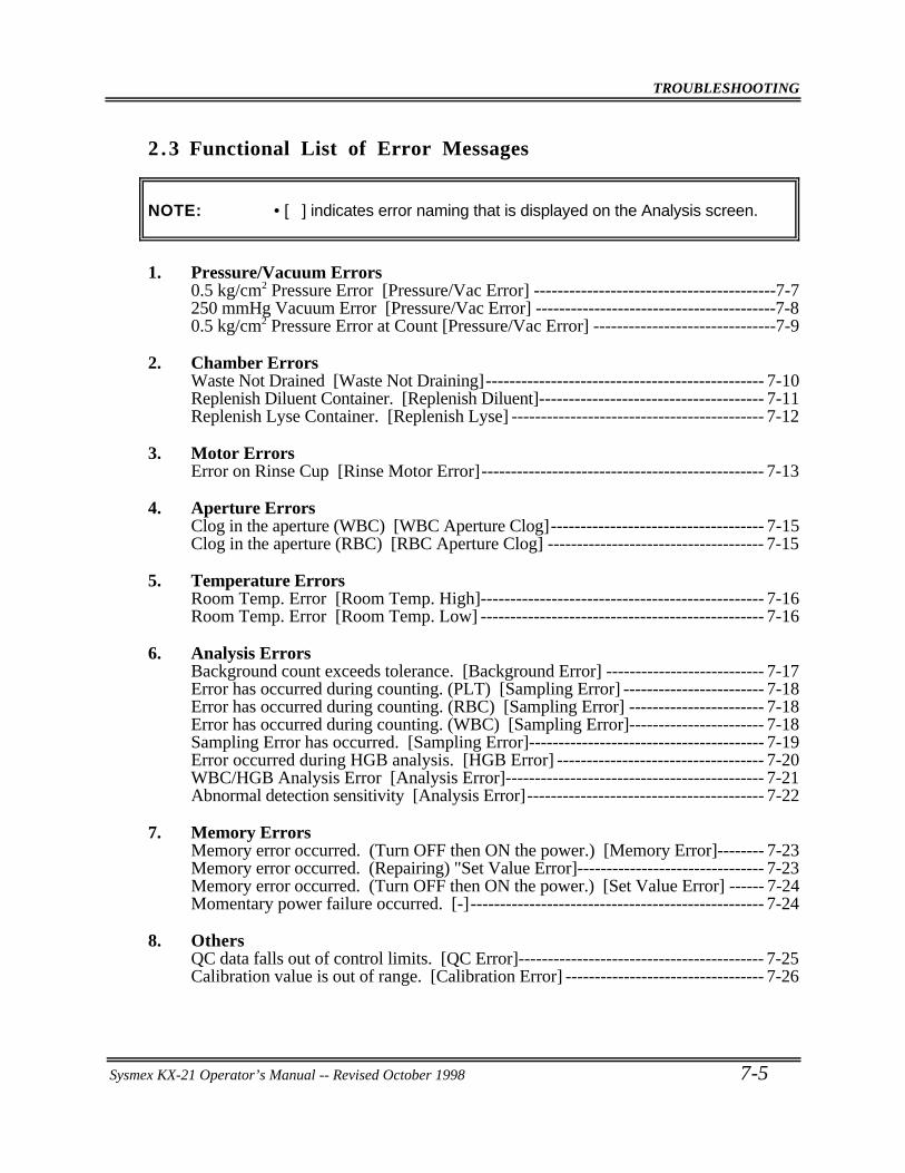
TROUBLESHOOTING
Sysmex KX-21 Operator’s Manual -- Revised October 1998 7-5
2 . 3 Functional List of Error Messages
NOTE: • [ ] indicates error naming that is displayed on the Analysis screen.
1. Pressure/Vacuum Errors0.5 kg/cm2 Pressure Error [Pressure/Vac Error] -----------------------------------------7-7250 mmHg Vacuum Error [Pressure/Vac Error] -----------------------------------------7-80.5 kg/cm2 Pressure Error at Count [Pressure/Vac Error] -------------------------------7-9
2. Chamber ErrorsWaste Not Drained [Waste Not Draining]----------------------------------------------- 7-10Replenish Diluent Container. [Replenish Diluent]-------------------------------------- 7-11Replenish Lyse Container. [Replenish Lyse] ------------------------------------------- 7-12
3. Motor ErrorsError on Rinse Cup [Rinse Motor Error]------------------------------------------------ 7-13
4. Aperture ErrorsClog in the aperture (WBC) [WBC Aperture Clog]------------------------------------ 7-15Clog in the aperture (RBC) [RBC Aperture Clog] ------------------------------------- 7-15
5. Temperature ErrorsRoom Temp. Error [Room Temp. High]------------------------------------------------ 7-16Room Temp. Error [Room Temp. Low] ------------------------------------------------ 7-16
6. Analysis ErrorsBackground count exceeds tolerance. [Background Error] --------------------------- 7-17Error has occurred during counting. (PLT) [Sampling Error] ------------------------ 7-18Error has occurred during counting. (RBC) [Sampling Error] ----------------------- 7-18Error has occurred during counting. (WBC) [Sampling Error]----------------------- 7-18Sampling Error has occurred. [Sampling Error]---------------------------------------- 7-19Error occurred during HGB analysis. [HGB Error] ----------------------------------- 7-20WBC/HGB Analysis Error [Analysis Error]-------------------------------------------- 7-21Abnormal detection sensitivity [Analysis Error]---------------------------------------- 7-22
7. Memory ErrorsMemory error occurred. (Turn OFF then ON the power.) [Memory Error]-------- 7-23Memory error occurred. (Repairing) "Set Value Error]-------------------------------- 7-23Memory error occurred. (Turn OFF then ON the power.) [Set Value Error] ------ 7-24Momentary power failure occurred. [-]-------------------------------------------------- 7-24
8. OthersQC data falls out of control limits. [QC Error]------------------------------------------ 7-25Calibration value is out of range. [Calibration Error] ---------------------------------- 7-26
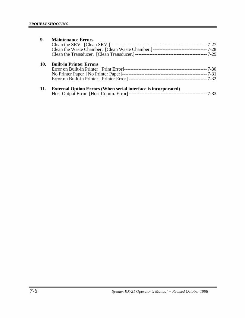
TROUBLESHOOTING
7-6 Sysmex KX-21 Operator’s Manual -- Revised October 1998
9. Maintenance ErrorsClean the SRV. [Clean SRV.] ------------------------------------------------------------ 7-27Clean the Waste Chamber. [Clean Waste Chamber.] ---------------------------------- 7-28Clean the Transducer. [Clean Transducer.] --------------------------------------------- 7-29
10. Built-in Printer ErrorsError on Built-in Printer [Print Error]---------------------------------------------------- 7-30No Printer Paper [No Printer Paper]----------------------------------------------------- 7-31Error on Built-in Printer [Printer Error] ------------------------------------------------- 7-32
11. External Option Errors (When serial interface is incorporated)Host Output Error [Host Comm. Error]------------------------------------------------- 7-33
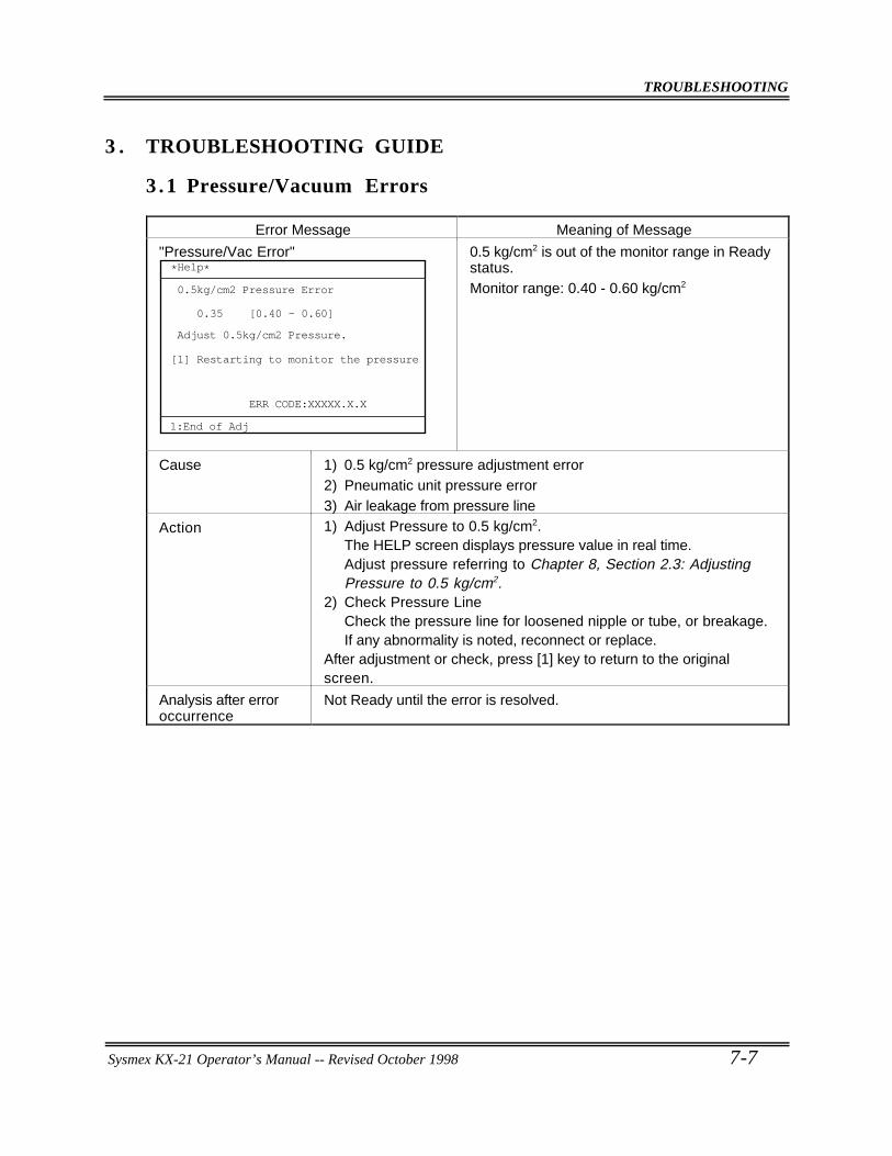
TROUBLESHOOTING
Sysmex KX-21 Operator’s Manual -- Revised October 1998 7-7
3 . TROUBLESHOOTING GUIDE
3 .1 Pressure/Vacuum Errors
Error Message Meaning of Message
"Pressure/Vac Error"
0.35 [0.40 - 0.60]
ERR CODE:XXXXX.X.X
*Help*
0.5kg/cm2 Pressure Error
Adjust 0.5kg/cm2 Pressure.
Restarting to monitor the pressure[1]
1:End of Adj
0.5 kg/cm2 is out of the monitor range in Readystatus.Monitor range: 0.40 - 0.60 kg/cm2
Cause 1) 0.5 kg/cm2 pressure adjustment error2) Pneumatic unit pressure error3) Air leakage from pressure line
Action 1) Adjust Pressure to 0.5 kg/cm2.The HELP screen displays pressure value in real time.Adjust pressure referring to Chapter 8, Section 2.3: AdjustingPressure to 0.5 kg/cm2.
2) Check Pressure LineCheck the pressure line for loosened nipple or tube, or breakage.If any abnormality is noted, reconnect or replace.
After adjustment or check, press [1] key to return to the originalscreen.
Analysis after erroroccurrence
Not Ready until the error is resolved.
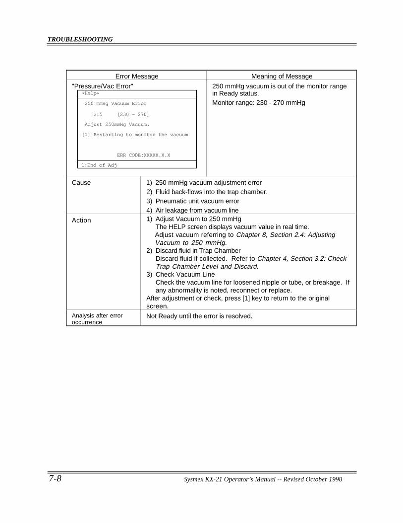
TROUBLESHOOTING
7-8 Sysmex KX-21 Operator’s Manual -- Revised October 1998
Error Message Meaning of Message
"Pressure/Vac Error"
ERR CODE:XXXXX.X.X
*Help*
250 mmHg Vacuum Error
Adjust 250mmHg Vacuum.
Restarting to monitor the vacuum[1]
1:End of Adj
215 [230 - 270]
250 mmHg vacuum is out of the monitor rangein Ready status.Monitor range: 230 - 270 mmHg
Cause 1) 250 mmHg vacuum adjustment error2) Fluid back-flows into the trap chamber.3) Pneumatic unit vacuum error4) Air leakage from vacuum line
Action 1) Adjust Vacuum to 250 mmHgThe HELP screen displays vacuum value in real time.Adjust vacuum referring to Chapter 8, Section 2.4: AdjustingVacuum to 250 mmHg.
2) Discard fluid in Trap ChamberDiscard fluid if collected. Refer to Chapter 4, Section 3.2: CheckTrap Chamber Level and Discard.
3) Check Vacuum LineCheck the vacuum line for loosened nipple or tube, or breakage. Ifany abnormality is noted, reconnect or replace.
After adjustment or check, press [1] key to return to the originalscreen.
Analysis after erroroccurrence
Not Ready until the error is resolved.
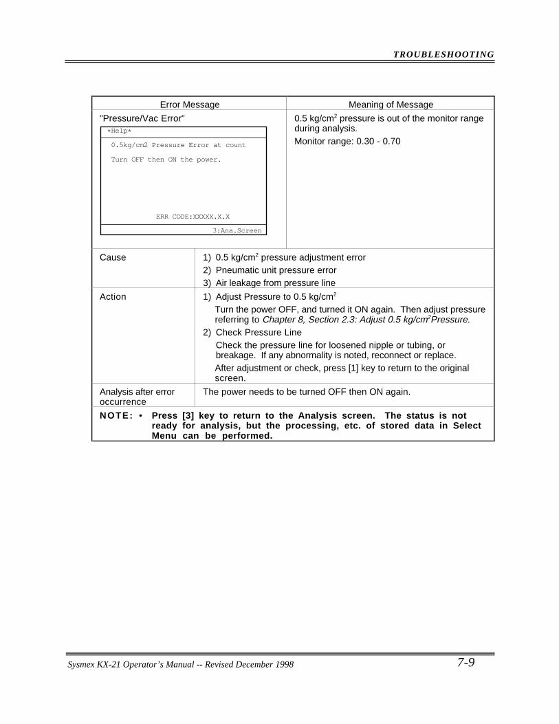
TROUBLESHOOTING
Sysmex KX-21 Operator’s Manual -- Revised October 1998 7-9
Error Message Meaning of Message
"Pressure/Vac Error"
ERR CODE:XXXXX.X.X
*Help*
0.5kg/cm2 Pressure Error at count
Turn OFF then ON the power.
3:Ana.Screen
0.5 kg/cm2 pressure is out of the monitor rangeduring analysis.Monitor range: 0.30 - 0.70
Cause 1) 0.5 kg/cm2 pressure adjustment error2) Pneumatic unit pressure error3) Air leakage from pressure line
Action 1) Adjust Pressure to 0.5 kg/cm2
Turn the power OFF, and turned it ON again. Then adjust pressurereferring to Chapter 8, Section 2.3: Adjust 0.5 kg/cm2Pressure.
2) Check Pressure LineCheck the pressure line for loosened nipple or tubing, orbreakage. If any abnormality is noted, reconnect or replace.After adjustment or check, press [1] key to return to the originalscreen.
Analysis after erroroccurrence
The power needs to be turned OFF then ON again.
NOTE: • Press [3] key to return to the Analysis screen. The status is notready for analysis, but the processing, etc. of stored data in SelectMenu can be performed.
Sysmex KX-21 Operator’s Manual -- Revised December 1998
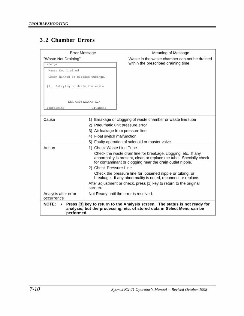
TROUBLESHOOTING
7-10 Sysmex KX-21 Operator’s Manual -- Revised October 1998
3 .2 Chamber Errors
Error Message Meaning of Message
"Waste Not Draining"
ERR CODE:XXXXX.X.X
Waste Not Drained
Check kinked or blocked tubings.
Retrying to drain the waste
*Help*
3:Cancel1:Draining
[1]
Waste in the waste chamber can not be drainedwithin the prescribed draining time.
Cause 1) Breakage or clogging of waste chamber or waste line tube2) Pneumatic unit pressure error3) Air leakage from pressure line4) Float switch malfunction5) Faulty operation of solenoid or master valve
Action 1) Check Waste Line TubeCheck the waste drain line for breakage, clogging, etc. If anyabnormality is present, clean or replace the tube. Specially checkfor contaminant or clogging near the drain outlet nipple.
2) Check Pressure LineCheck the pressure line for loosened nipple or tubing, orbreakage. If any abnormality is noted, reconnect or replace.
After adjustment or check, press [1] key to return to the originalscreen.
Analysis after erroroccurrence
Not Ready until the error is resolved.
NOTE: • Press [3] key to return to the Analysis screen. The status is not ready foranalysis, but the processing, etc. of stored data in Select Menu can beperformed.
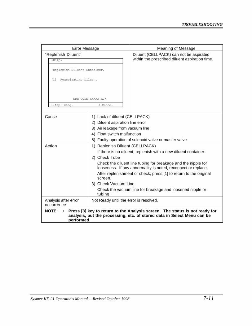
TROUBLESHOOTING
Sysmex KX-21 Operator’s Manual -- Revised October 1998 7-11
Error Message Meaning of Message
"Replenish Diluent"
ERR CODE:XXXXX.X.X
*Help*
1:Asp. Reag. 3:Cancel
Replenish Diluent Container.
Reaspirating Diluent[1]
Diluent (CELLPACK) can not be aspiratedwithin the prescribed diluent aspiration time.
Cause 1) Lack of diluent (CELLPACK)2) Diluent aspiration line error3) Air leakage from vacuum line4) Float switch malfunction5) Faulty operation of solenoid valve or master valve
Action 1) Replenish Diluent (CELLPACK)If there is no diluent, replenish with a new diluent container.
2) Check TubeCheck the diluent line tubing for breakage and the nipple forlooseness. If any abnormality is noted, reconnect or replace.After replenishment or check, press [1] to return to the originalscreen.
3) Check Vacuum LineCheck the vacuum line for breakage and loosened nipple ortubing.
Analysis after erroroccurrence
Not Ready until the error is resolved.
NOTE: • Press [3] key to return to the Analysis screen. The status is not ready foranalysis, but the processing, etc. of stored data in Select Menu can beperformed.
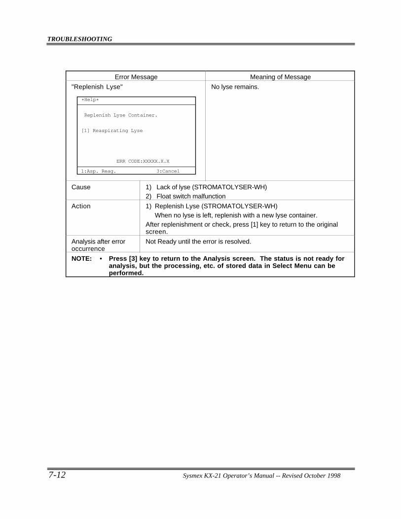
TROUBLESHOOTING
7-12 Sysmex KX-21 Operator’s Manual -- Revised October 1998
Error Message Meaning of Message
"Replenish Lyse"
ERR CODE:XXXXX.X.X
*Help*
1:Asp. Reag. 3:Cancel
Replenish Lyse Container.
Reaspirating Lyse[1]
No lyse remains.
Cause 1) Lack of lyse (STROMATOLYSER-WH)2) Float switch malfunction
Action 1) Replenish Lyse (STROMATOLYSER-WH)When no lyse is left, replenish with a new lyse container.
After replenishment or check, press [1] key to return to the originalscreen.
Analysis after erroroccurrence
Not Ready until the error is resolved.
NOTE: • Press [3] key to return to the Analysis screen. The status is not ready foranalysis, but the processing, etc. of stored data in Select Menu can beperformed.
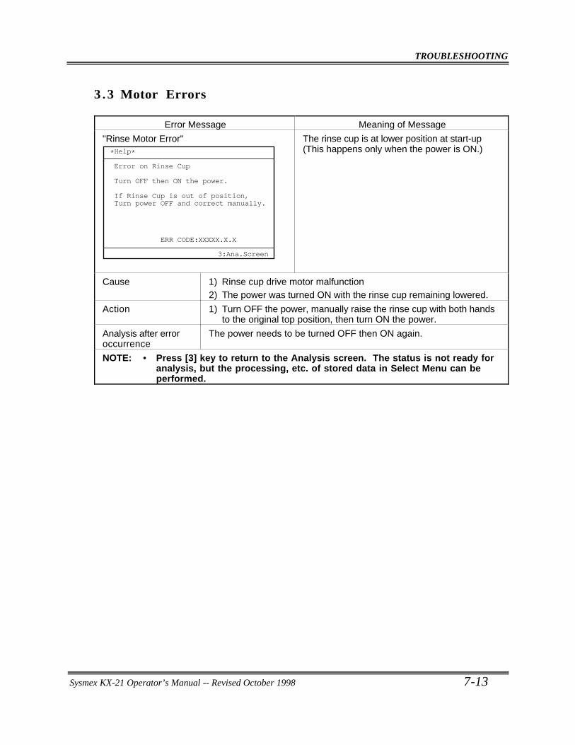
TROUBLESHOOTING
Sysmex KX-21 Operator’s Manual -- Revised October 1998 7-13
3 .3 Motor Errors
Error Message Meaning of Message
"Rinse Motor Error"
ERR CODE:XXXXX.X.X
*Help*
Error on Rinse Cup
Turn OFF then ON the power.
If Rinse Cup is out of position,Turn power OFF and correct manually.
3:Ana.Screen
The rinse cup is at lower position at start-up(This happens only when the power is ON.)
Cause 1) Rinse cup drive motor malfunction2) The power was turned ON with the rinse cup remaining lowered.
Action 1) Turn OFF the power, manually raise the rinse cup with both handsto the original top position, then turn ON the power.
Analysis after erroroccurrence
The power needs to be turned OFF then ON again.
NOTE: • Press [3] key to return to the Analysis screen. The status is not ready foranalysis, but the processing, etc. of stored data in Select Menu can beperformed.
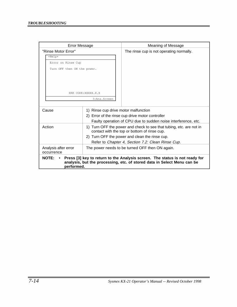
TROUBLESHOOTING
7-14 Sysmex KX-21 Operator’s Manual -- Revised October 1998
Error Message Meaning of Message
"Rinse Motor Error"
ERR CODE:XXXXX.X.X
*Help*
Error on Rinse Cup
Turn OFF then ON the power.
3:Ana.Screen
The rinse cup is not operating normally.
Cause 1) Rinse cup drive motor malfunction2) Error of the rinse cup drive motor controller
Faulty operation of CPU due to sudden noise interference, etc.
Action 1) Turn OFF the power and check to see that tubing, etc. are not incontact with the top or bottom of rinse cup.
2) Turn OFF the power and clean the rinse cup.Refer to Chapter 4, Section 7.2: Clean Rinse Cup.
Analysis after erroroccurrence
The power needs to be turned OFF then ON again.
NOTE: • Press [3] key to return to the Analysis screen. The status is not ready foranalysis, but the processing, etc. of stored data in Select Menu can beperformed.
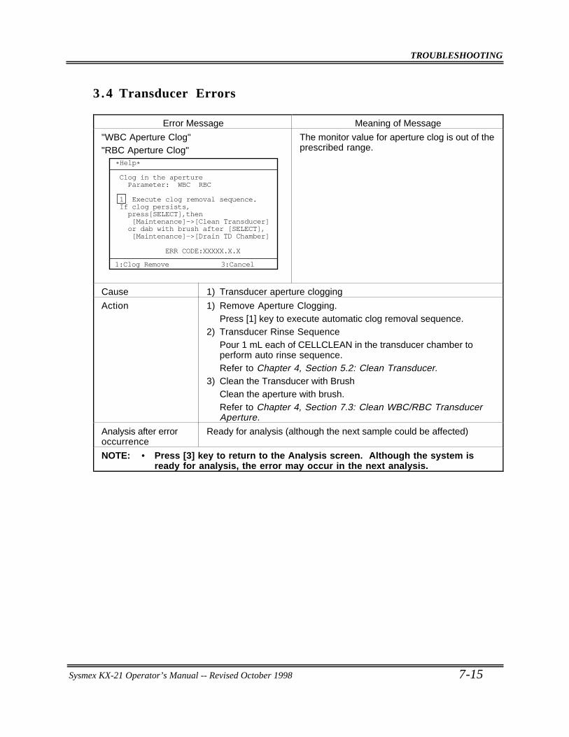
TROUBLESHOOTING
Sysmex KX-21 Operator’s Manual -- Revised October 1998 7-15
3 .4 Transducer Errors
Error Message Meaning of Message
"WBC Aperture Clog""RBC Aperture Clog"
Clog in the aperture Parameter: WBC RBC
1 Execute clog removal sequence.If clog persists, press[SELECT],then [Maintenance]->[Clean Transducer] or dab with brush after [SELECT], [Maintenance]->[Drain TD Chamber]
ERR CODE:XXXXX.X.X
1:Clog Remove
*Help*
3:Cancel
The monitor value for aperture clog is out of theprescribed range.
Cause 1) Transducer aperture clogging
Action 1) Remove Aperture Clogging.Press [1] key to execute automatic clog removal sequence.
2) Transducer Rinse SequencePour 1 mL each of CELLCLEAN in the transducer chamber toperform auto rinse sequence.Refer to Chapter 4, Section 5.2: Clean Transducer.
3) Clean the Transducer with BrushClean the aperture with brush.Refer to Chapter 4, Section 7.3: Clean WBC/RBC TransducerAperture.
Analysis after erroroccurrence
Ready for analysis (although the next sample could be affected)
NOTE: • Press [3] key to return to the Analysis screen. Although the system isready for analysis, the error may occur in the next analysis.
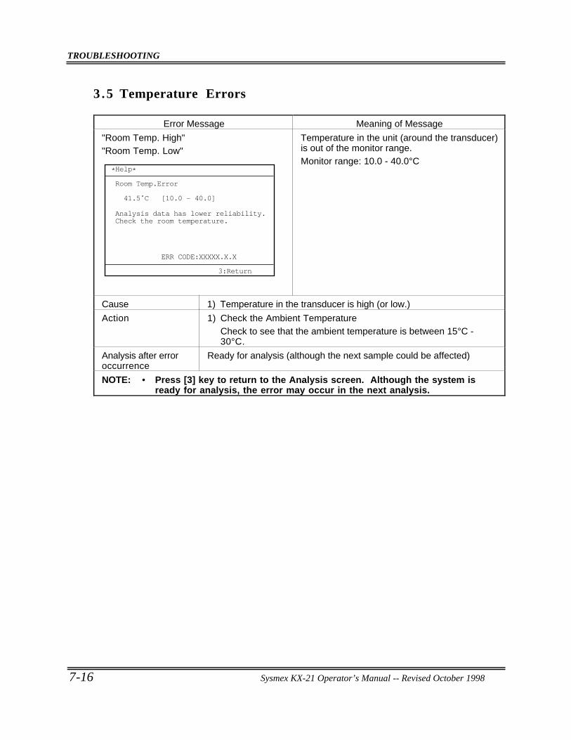
TROUBLESHOOTING
7-16 Sysmex KX-21 Operator’s Manual -- Revised October 1998
3 .5 Temperature Errors
Error Message Meaning of Message
"Room Temp. High""Room Temp. Low"
ERR CODE:XXXXX.X.X
*Help*
Room Temp.Error
Analysis data has lower reliability.Check the room temperature.
41.5˚C [10.0 - 40.0]
3:Return
Temperature in the unit (around the transducer)is out of the monitor range.Monitor range: 10.0 - 40.0°C
Cause 1) Temperature in the transducer is high (or low.)
Action 1) Check the Ambient TemperatureCheck to see that the ambient temperature is between 15°C -30°C.
Analysis after erroroccurrence
Ready for analysis (although the next sample could be affected)
NOTE: • Press [3] key to return to the Analysis screen. Although the system isready for analysis, the error may occur in the next analysis.
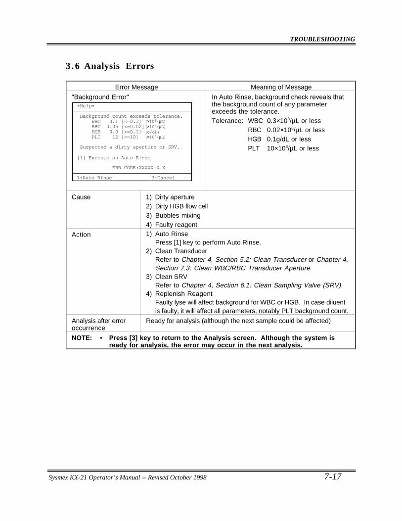
TROUBLESHOOTING
Sysmex KX-21 Operator’s Manual -- Revised October 1998 7-17
3 .6 Analysis Errors
Error Message Meaning of Message
"Background Error"
Background count exceeds tolerance. WBC 0.1 [<=0.3] (×103/µL) RBC 0.05 [<=0.02](×106/µL) HGB 0.0 [<=0.1] (g/dL) PLT 12 [<=10] (×103/µL)
ERR CODE:XXXXX.X.X
*Help*
3:Cancel1:Auto Rinse
Suspected a dirty aperture or SRV.
Execute an Auto Rinse.[1]
In Auto Rinse, background check reveals thatthe background count of any parameterexceeds the tolerance.Tolerance: WBC 0.3×10³/µL or less
RBC 0.02×10⁶/µL or lessHGB 0.1g/dL or lessPLT 10×103/µL or less
Cause 1) Dirty aperture2) Dirty HGB flow cell3) Bubbles mixing4) Faulty reagent
Action 1) Auto RinsePress [1] key to perform Auto Rinse.
2) Clean TransducerRefer to Chapter 4, Section 5.2: Clean Transducer or Chapter 4,Section 7.3: Clean WBC/RBC Transducer Aperture.
3) Clean SRVRefer to Chapter 4, Section 6.1: Clean Sampling Valve (SRV).
4) Replenish ReagentFaulty lyse will affect background for WBC or HGB. In case diluentis faulty, it will affect all parameters, notably PLT background count.
Analysis after erroroccurrence
Ready for analysis (although the next sample could be affected)
NOTE: • Press [3] key to return to the Analysis screen. Although the system isready for analysis, the error may occur in the next analysis.
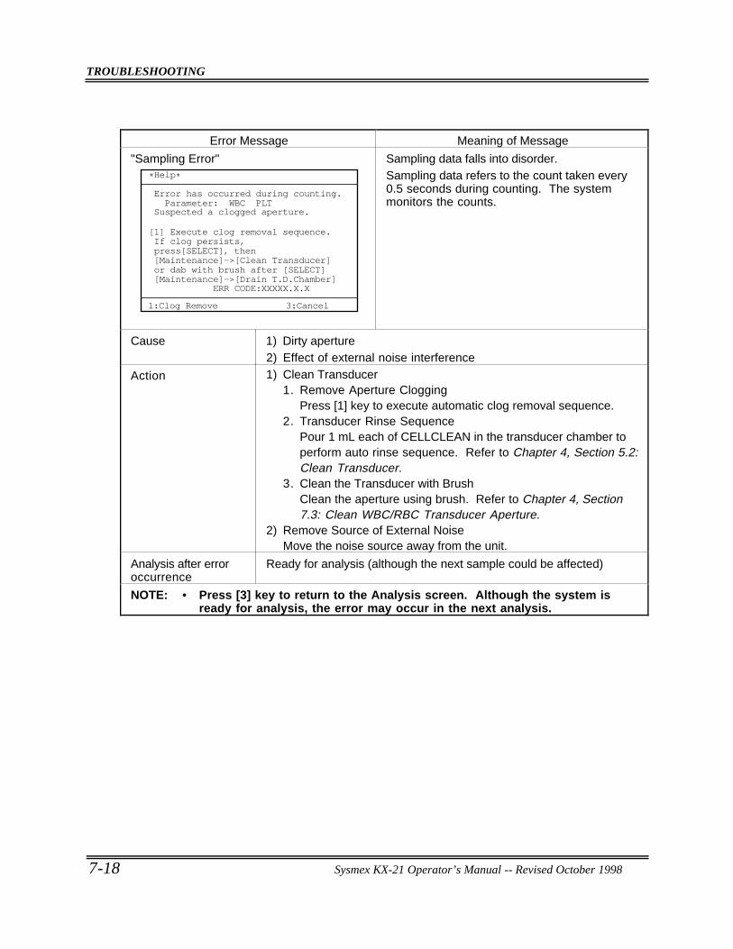
TROUBLESHOOTING
7-18 Sysmex KX-21 Operator’s Manual -- Revised October 1998
Error Message Meaning of Message
"Sampling Error"
ERR CODE:XXXXX.X.X
Execute clog removal sequence.If clog persists,press[SELECT], then[Maintenance]->[Clean Transducer]or dab with brush after [SELECT][Maintenance]->[Drain T.D.Chamber]
[1]
1:Clog Remove
*Help*
Error has occurred during counting. Parameter: WBC PLTSuspected a clogged aperture.
3:Cancel
Sampling data falls into disorder.Sampling data refers to the count taken every0.5 seconds during counting. The systemmonitors the counts.
Cause 1) Dirty aperture2) Effect of external noise interference
Action 1) Clean Transducer1. Remove Aperture Clogging
Press [1] key to execute automatic clog removal sequence.2. Transducer Rinse Sequence
Pour 1 mL each of CELLCLEAN in the transducer chamber toperform auto rinse sequence. Refer to Chapter 4, Section 5.2:Clean Transducer.
3. Clean the Transducer with BrushClean the aperture using brush. Refer to Chapter 4, Section7.3: Clean WBC/RBC Transducer Aperture.
2) Remove Source of External NoiseMove the noise source away from the unit.
Analysis after erroroccurrence
Ready for analysis (although the next sample could be affected)
NOTE: • Press [3] key to return to the Analysis screen. Although the system isready for analysis, the error may occur in the next analysis.
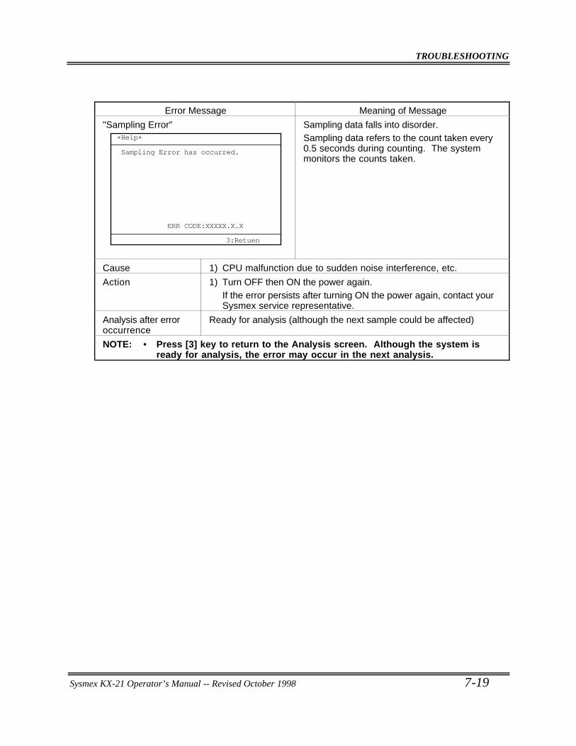
TROUBLESHOOTING
Sysmex KX-21 Operator’s Manual -- Revised October 1998 7-19
Error Message Meaning of Message
"Sampling Error"
ERR CODE:XXXXX.X.X
*Help*
Sampling Error has occurred.
3:Retuen
Sampling data falls into disorder.Sampling data refers to the count taken every0.5 seconds during counting. The systemmonitors the counts taken.
Cause 1) CPU malfunction due to sudden noise interference, etc.
Action 1) Turn OFF then ON the power again.If the error persists after turning ON the power again, contact yourSysmex service representative.
Analysis after erroroccurrence
Ready for analysis (although the next sample could be affected)
NOTE: • Press [3] key to return to the Analysis screen. Although the system isready for analysis, the error may occur in the next analysis.
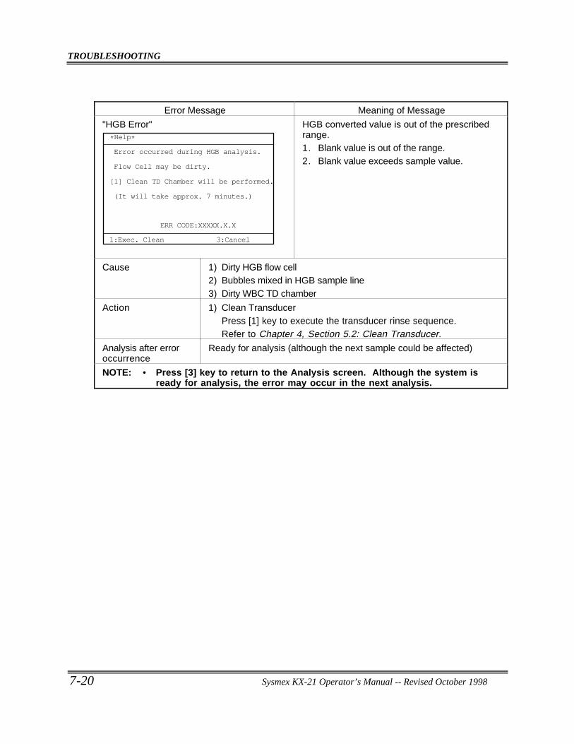
TROUBLESHOOTING
7-20 Sysmex KX-21 Operator’s Manual -- Revised October 1998
Error Message Meaning of Message
"HGB Error"*Help*
3:Cancel
Clean TD Chamber will be performed.
(It will take approx. 7 minutes.)
[1]
Error occurred during HGB analysis.
Flow Cell may be dirty.
ERR CODE:XXXXX.X.X
1:Exec. Clean
HGB converted value is out of the prescribedrange.1. Blank value is out of the range.2. Blank value exceeds sample value.
Cause 1) Dirty HGB flow cell2) Bubbles mixed in HGB sample line3) Dirty WBC TD chamber
Action 1) Clean TransducerPress [1] key to execute the transducer rinse sequence.Refer to Chapter 4, Section 5.2: Clean Transducer.
Analysis after erroroccurrence
Ready for analysis (although the next sample could be affected)
NOTE: • Press [3] key to return to the Analysis screen. Although the system isready for analysis, the error may occur in the next analysis.
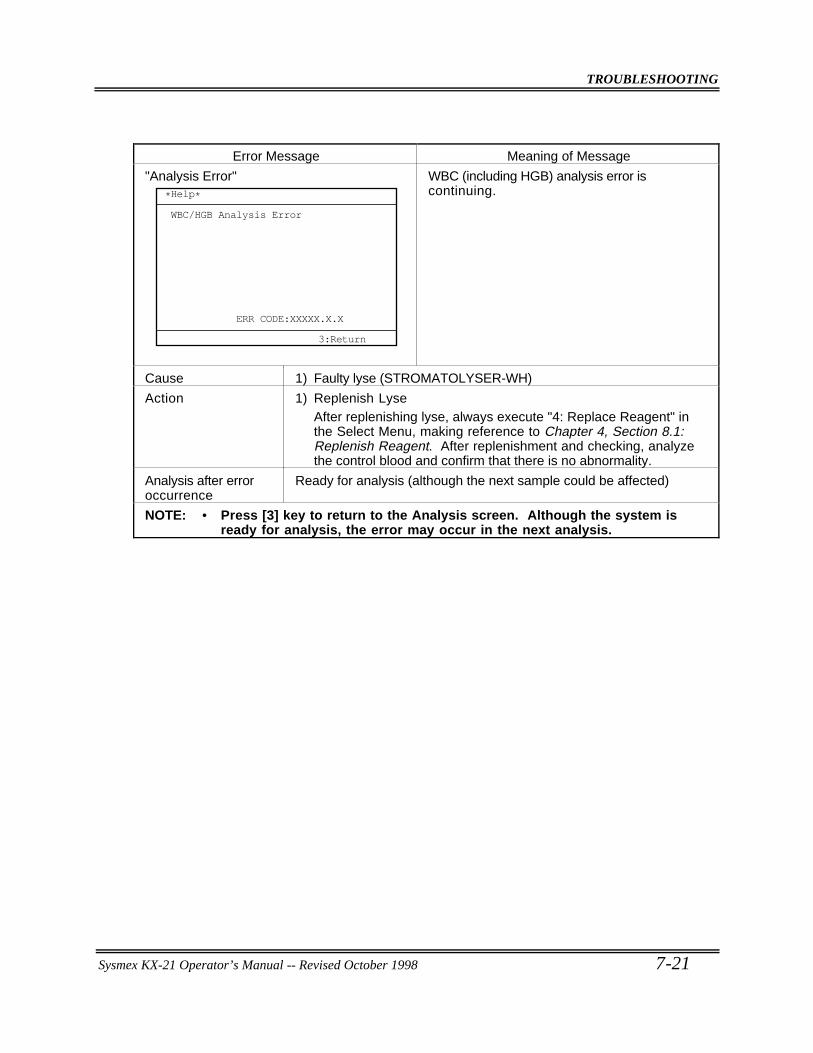
TROUBLESHOOTING
Sysmex KX-21 Operator’s Manual -- Revised October 1998 7-21
Error Message Meaning of Message
"Analysis Error"
ERR CODE:XXXXX.X.X
*Help*
3:Return
WBC/HGB Analysis Error
WBC (including HGB) analysis error iscontinuing.
Cause 1) Faulty lyse (STROMATOLYSER-WH)
Action 1) Replenish LyseAfter replenishing lyse, always execute "4: Replace Reagent" inthe Select Menu, making reference to Chapter 4, Section 8.1:Replenish Reagent. After replenishment and checking, analyzethe control blood and confirm that there is no abnormality.
Analysis after erroroccurrence
Ready for analysis (although the next sample could be affected)
NOTE: • Press [3] key to return to the Analysis screen. Although the system isready for analysis, the error may occur in the next analysis.
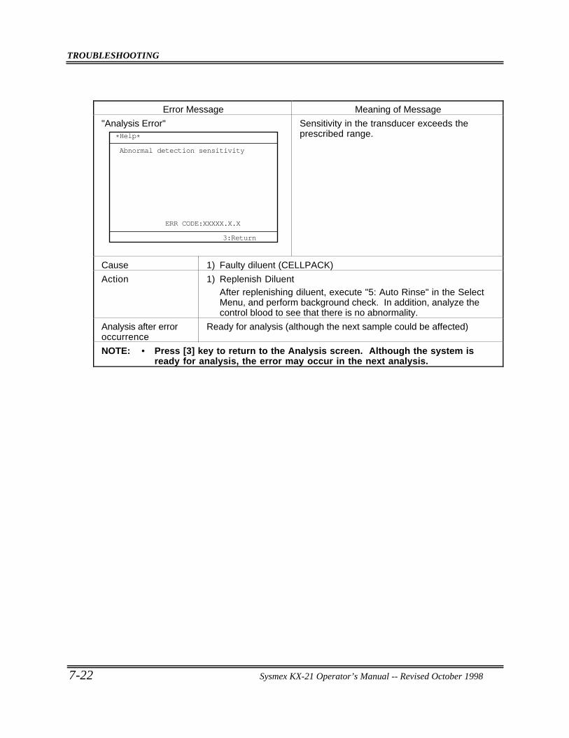
TROUBLESHOOTING
7-22 Sysmex KX-21 Operator’s Manual -- Revised October 1998
Error Message Meaning of Message
"Analysis Error"
ERR CODE:XXXXX.X.X
*Help*
3:Return
Abnormal detection sensitivity
Sensitivity in the transducer exceeds theprescribed range.
Cause 1) Faulty diluent (CELLPACK)
Action 1) Replenish DiluentAfter replenishing diluent, execute "5: Auto Rinse" in the SelectMenu, and perform background check. In addition, analyze thecontrol blood to see that there is no abnormality.
Analysis after erroroccurrence
Ready for analysis (although the next sample could be affected)
NOTE: • Press [3] key to return to the Analysis screen. Although the system isready for analysis, the error may occur in the next analysis.
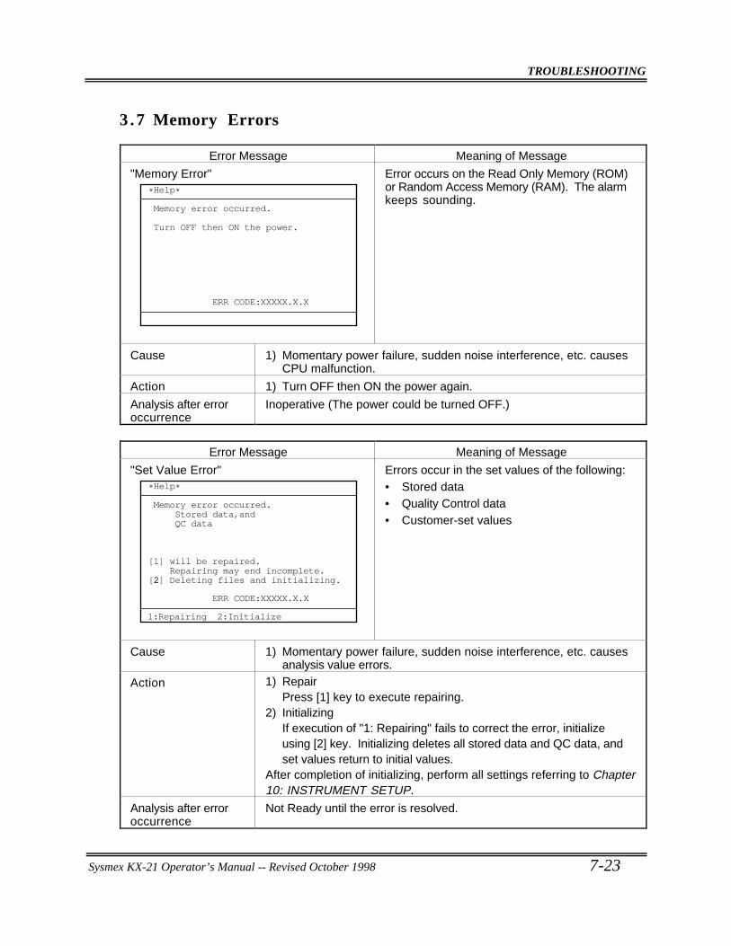
TROUBLESHOOTING
Sysmex KX-21 Operator’s Manual -- Revised October 1998 7-23
3 .7 Memory Errors
Error Message Meaning of Message
"Memory Error"
ERR CODE:XXXXX.X.X
*Help*
Memory error occurred.
Turn OFF then ON the power.
Error occurs on the Read Only Memory (ROM)or Random Access Memory (RAM). The alarmkeeps sounding.
Cause 1) Momentary power failure, sudden noise interference, etc. causesCPU malfunction.
Action 1) Turn OFF then ON the power again.
Analysis after erroroccurrence
Inoperative (The power could be turned OFF.)
Error Message Meaning of Message
"Set Value Error"
ERR CODE:XXXXX.X.X
*Help*
Memory error occurred. Stored data,and QC data
will be repaired. Repairing may end incomplete.2 Deleting files and initializing.
[1]
[2]
1:Repairing 2:Initialize
Errors occur in the set values of the following:• Stored data• Quality Control data• Customer-set values
Cause 1) Momentary power failure, sudden noise interference, etc. causesanalysis value errors.
Action 1) RepairPress [1] key to execute repairing.
2) InitializingIf execution of "1: Repairing" fails to correct the error, initializeusing [2] key. Initializing deletes all stored data and QC data, andset values return to initial values.
After completion of initializing, perform all settings referring to Chapter10: INSTRUMENT SETUP.
Analysis after erroroccurrence
Not Ready until the error is resolved.
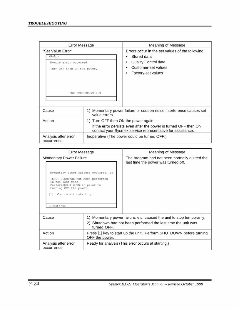
TROUBLESHOOTING
7-24 Sysmex KX-21 Operator’s Manual -- Revised October 1998
Error Message Meaning of Message
"Set Value Error"
ERR CODE:XXXXX.X.X
*Help*
Memory error occurred.
Turn OFF then ON the power.
Errors occur in the set values of the following:• Stored data• Quality Control data• Customer-set values• Factory-set values
Cause 1) Momentary power failure or sudden noise interference causes setvalue errors.
Action 1) Turn OFF then ON the power again.If the error persists even after the power is turned OFF then ON,contact your Sysmex service representative for assistance.
Analysis after erroroccurrence
Inoperative (The power could be turned OFF.)
Error Message Meaning of Message
Momentary Power Failure
Momentary power failure occurred, or
[SHUT DOWN]has not been performedin the last time.Perform[SHUT DOWN]in prior toturning OFF the power.
Continue to start up.
1:Continue
[1]
The program had not been normally quitted thelast time the power was turned off.
Cause 1) Momentary power failure, etc. caused the unit to stop temporarily.2) Shutdown had not been performed the last time the unit was
turned OFF.
Action Press [1] key to start up the unit. Perform SHUTDOWN before turningOFF the power.
Analysis after erroroccurrence
Ready for analysis (This error occurs at starting.)
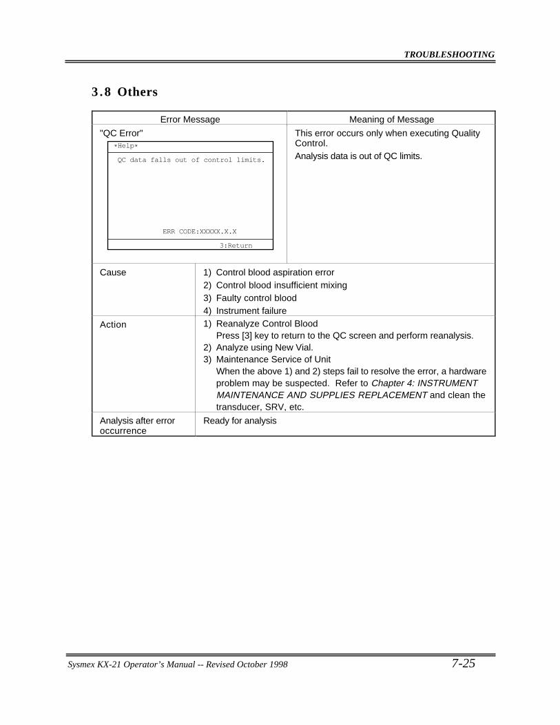
TROUBLESHOOTING
Sysmex KX-21 Operator’s Manual -- Revised October 1998 7-25
3 .8 Others
Error Message Meaning of Message
"QC Error"
ERR CODE:XXXXX.X.X
*Help*
3:Return
QC data falls out of control limits.
This error occurs only when executing QualityControl.Analysis data is out of QC limits.
Cause 1) Control blood aspiration error2) Control blood insufficient mixing3) Faulty control blood4) Instrument failure
Action 1) Reanalyze Control BloodPress [3] key to return to the QC screen and perform reanalysis.
2) Analyze using New Vial.3) Maintenance Service of Unit
When the above 1) and 2) steps fail to resolve the error, a hardwareproblem may be suspected. Refer to Chapter 4: INSTRUMENTMAINTENANCE AND SUPPLIES REPLACEMENT and clean thetransducer, SRV, etc.
Analysis after erroroccurrence
Ready for analysis
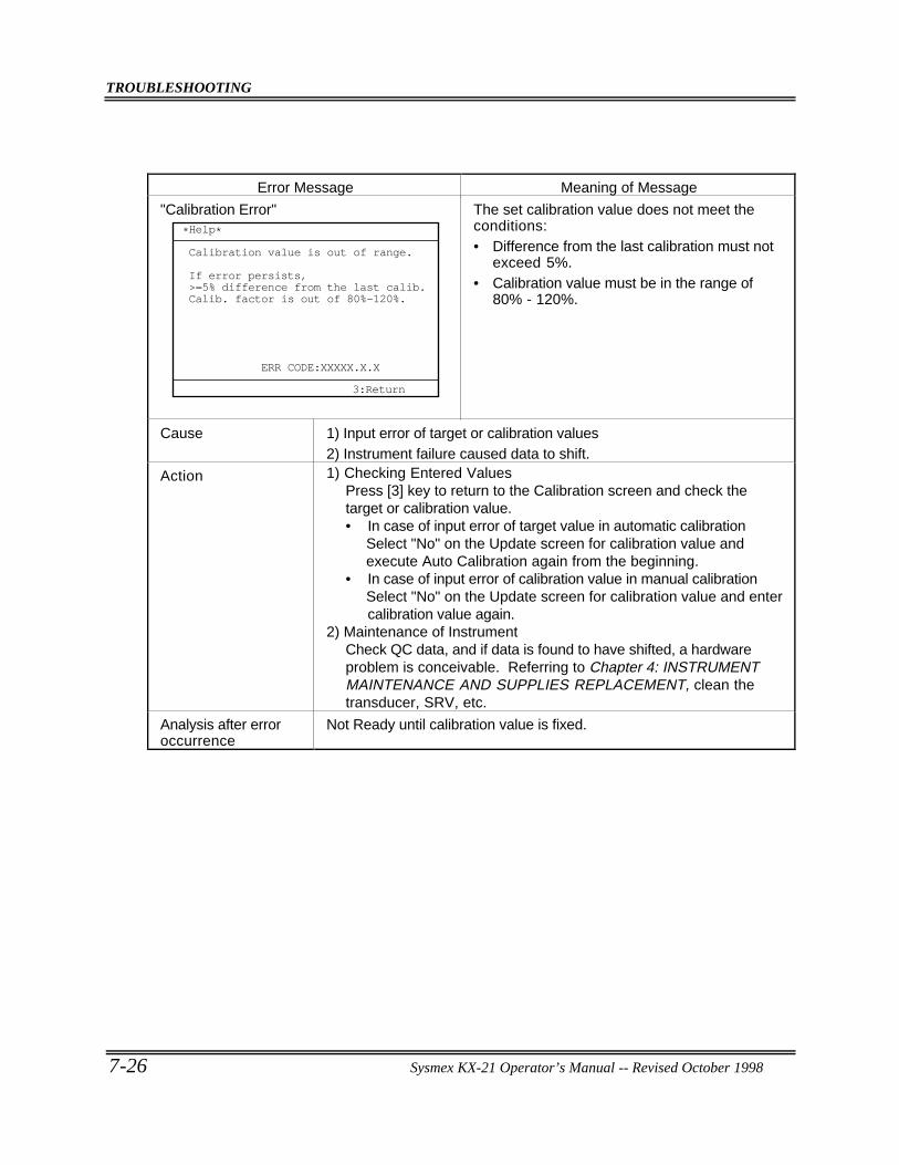
TROUBLESHOOTING
7-26 Sysmex KX-21 Operator’s Manual -- Revised October 1998
Error Message Meaning of Message
"Calibration Error"
ERR CODE:XXXXX.X.X
*Help*
Calibration value is out of range.
If error persists,>=5% difference from the last calib.Calib. factor is out of 80%-120%.
3:Return
The set calibration value does not meet theconditions:• Difference from the last calibration must not
exceed 5%.• Calibration value must be in the range of
80% - 120%.
Cause 1) Input error of target or calibration values2) Instrument failure caused data to shift.
Action 1) Checking Entered ValuesPress [3] key to return to the Calibration screen and check thetarget or calibration value.• In case of input error of target value in automatic calibration
Select "No" on the Update screen for calibration value andexecute Auto Calibration again from the beginning.
• In case of input error of calibration value in manual calibrationSelect "No" on the Update screen for calibration value and entercalibration value again.
2) Maintenance of InstrumentCheck QC data, and if data is found to have shifted, a hardwareproblem is conceivable. Referring to Chapter 4: INSTRUMENTMAINTENANCE AND SUPPLIES REPLACEMENT, clean thetransducer, SRV, etc.
Analysis after erroroccurrence
Not Ready until calibration value is fixed.
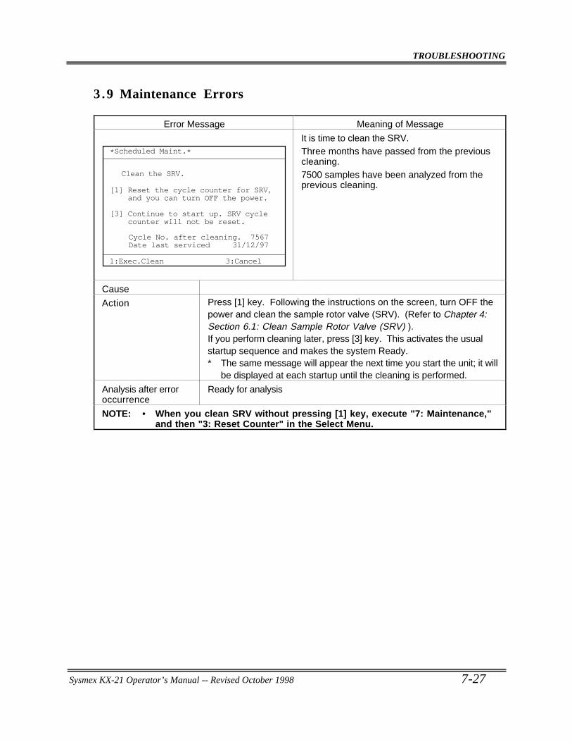
TROUBLESHOOTING
Sysmex KX-21 Operator’s Manual -- Revised October 1998 7-27
3 .9 Maintenance Errors
Error Message Meaning of Message
*Scheduled Maint.*
1:Exec.Clean
Clean the SRV.
Cycle No. after cleaning. 7567Date last serviced 31/12/97
Reset the cycle counter for SRV, and you can turn OFF the power.[1]
[3] Continue to start up. SRV cycle counter will not be reset.
3:Cancel
It is time to clean the SRV.Three months have passed from the previouscleaning.7500 samples have been analyzed from theprevious cleaning.
Cause
Action Press [1] key. Following the instructions on the screen, turn OFF thepower and clean the sample rotor valve (SRV). (Refer to Chapter 4:Section 6.1: Clean Sample Rotor Valve (SRV) ).If you perform cleaning later, press [3] key. This activates the usualstartup sequence and makes the system Ready.∗ The same message will appear the next time you start the unit; it will
be displayed at each startup until the cleaning is performed.
Analysis after erroroccurrence
Ready for analysis
NOTE: • When you clean SRV without pressing [1] key, execute "7: Maintenance,"and then "3: Reset Counter" in the Select Menu.
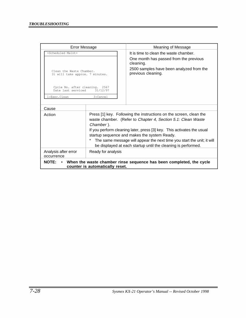
TROUBLESHOOTING
7-28 Sysmex KX-21 Operator’s Manual -- Revised October 1998
Error Message Meaning of Message*Scheduled Maint*
1:Exec.Clean
Cycle No. after cleaning. 2567Date last serviced 31/12/97
3:Cancel
Clean the Waste Chamber.It will take approx. 7 minutes.
It is time to clean the waste chamber.One month has passed from the previouscleaning.2500 samples have been analyzed from theprevious cleaning.
Cause
Action Press [1] key. Following the instructions on the screen, clean thewaste chamber. (Refer to Chapter 4, Section 5.1: Clean WasteChamber ).If you perform cleaning later, press [3] key. This activates the usualstartup sequence and makes the system Ready.∗ The same message will appear the next time you start the unit; it will
be displayed at each startup until the cleaning is performed.
Analysis after erroroccurrence
Ready for analysis
NOTE: • When the waste chamber rinse sequence has been completed, the cyclecounter is automatically reset.
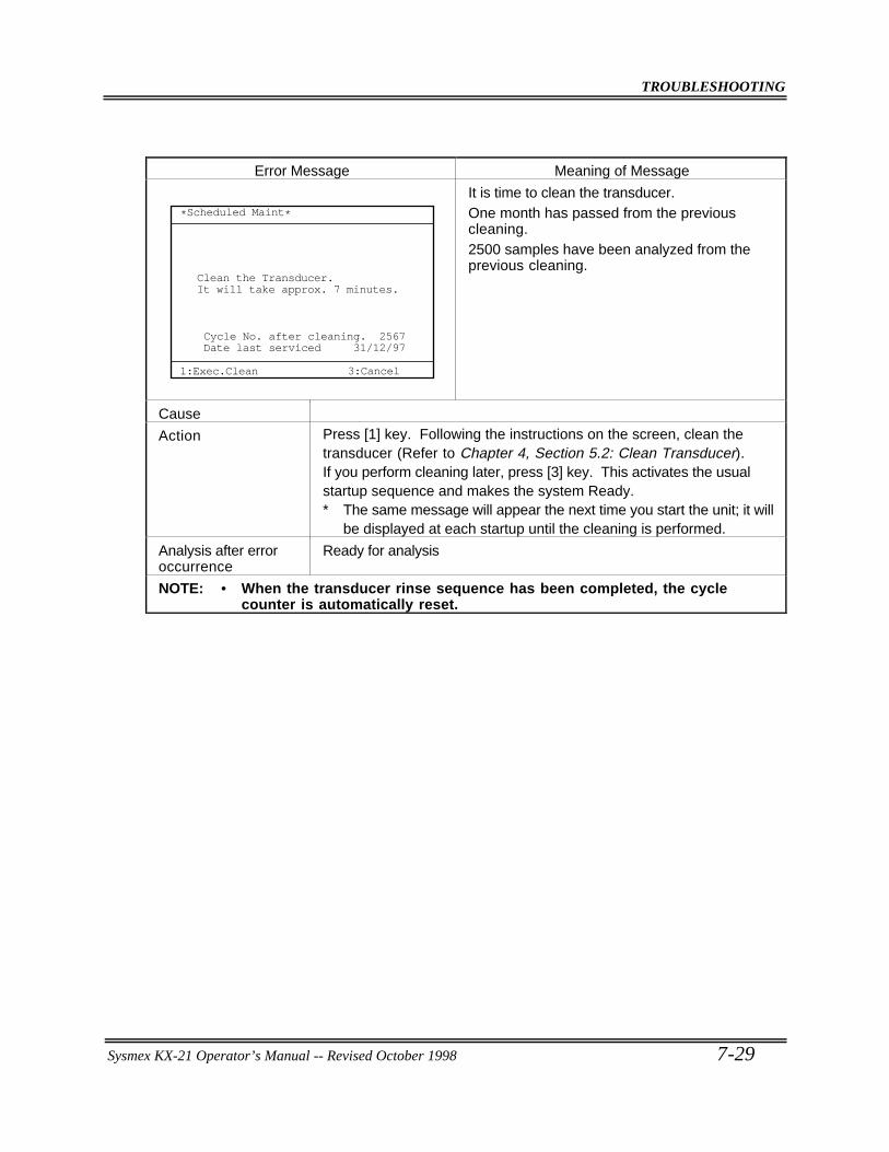
TROUBLESHOOTING
Sysmex KX-21 Operator’s Manual -- Revised October 1998 7-29
Error Message Meaning of Message
*Scheduled Maint*
1:Exec.Clean
Cycle No. after cleaning. 2567Date last serviced 31/12/97
3:Cancel
Clean the Transducer.It will take approx. 7 minutes.
It is time to clean the transducer.One month has passed from the previouscleaning.2500 samples have been analyzed from theprevious cleaning.
Cause
Action Press [1] key. Following the instructions on the screen, clean thetransducer (Refer to Chapter 4, Section 5.2: Clean Transducer).If you perform cleaning later, press [3] key. This activates the usualstartup sequence and makes the system Ready.∗ The same message will appear the next time you start the unit; it will
be displayed at each startup until the cleaning is performed.
Analysis after erroroccurrence
Ready for analysis
NOTE: • When the transducer rinse sequence has been completed, the cyclecounter is automatically reset.
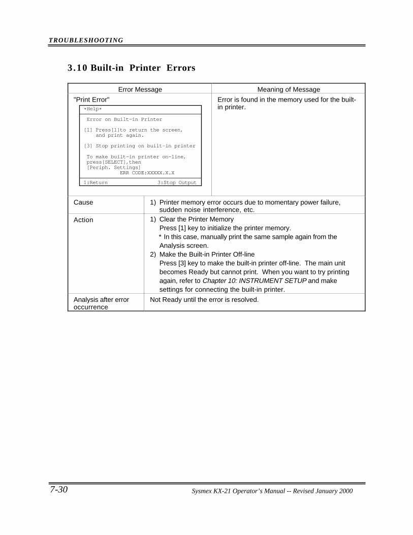
TROUBLESHOOTING
7-30 Sysmex KX-21 Operator’s Manual -- Revised October 1998
3.10 Built-in Printer Errors
Error Message Meaning of Message
"Print Error"
Press[1]to return the screen, and print again.
Stop printing on built-in printer
[1]
[3]
ERR CODE:XXXXX.X.X
*Help*
Error on Built-in Printer
To make built-in printer on-line,press[SELECT],then[Periph. Settings]
1:Return 3:Stop Output
Error is found in the memory used for the built-in printer.
Cause 1) Printer memory error occurs due to momentary power failure,sudden noise interference, etc.
Action 1) Clear the Printer MemoryPress [1] key to initialize the printer memory.∗ In this case, manually print the same sample again from theAnalysis screen.
2) Make the Built-in Printer Off-linePress [3] key to make the built-in printer off-line. The main unitbecomes Ready but cannot print. When you want to try printingagain, refer to Chapter 10: INSTRUMENT SETUP and makesettings for connecting the built-in printer.
Analysis after erroroccurrence
Not Ready until the error is resolved.
Sysmex KX-21 Operator’s Manual -- Revised January 2000
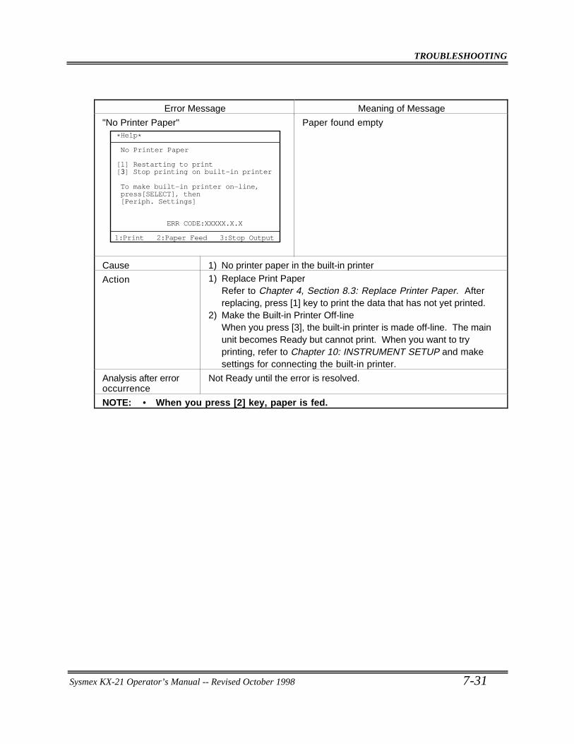
TROUBLESHOOTING
Sysmex KX-21 Operator’s Manual -- Revised October 1998 7-31
Error Message Meaning of Message
"No Printer Paper"
No Printer Paper
ERR CODE:XXXXX.X.X
1:Print 2:Paper Feed 3:Stop Output
*Help*
Restarting to print3 Stop printing on built-in printer
To make built-in printer on-line,press[SELECT], then[Periph. Settings]
[1][3]
Paper found empty
Cause 1) No printer paper in the built-in printer
Action 1) Replace Print PaperRefer to Chapter 4, Section 8.3: Replace Printer Paper. Afterreplacing, press [1] key to print the data that has not yet printed.
2) Make the Built-in Printer Off-lineWhen you press [3], the built-in printer is made off-line. The mainunit becomes Ready but cannot print. When you want to tryprinting, refer to Chapter 10: INSTRUMENT SETUP and makesettings for connecting the built-in printer.
Analysis after erroroccurrence
Not Ready until the error is resolved.
NOTE: • When you press [2] key, paper is fed.
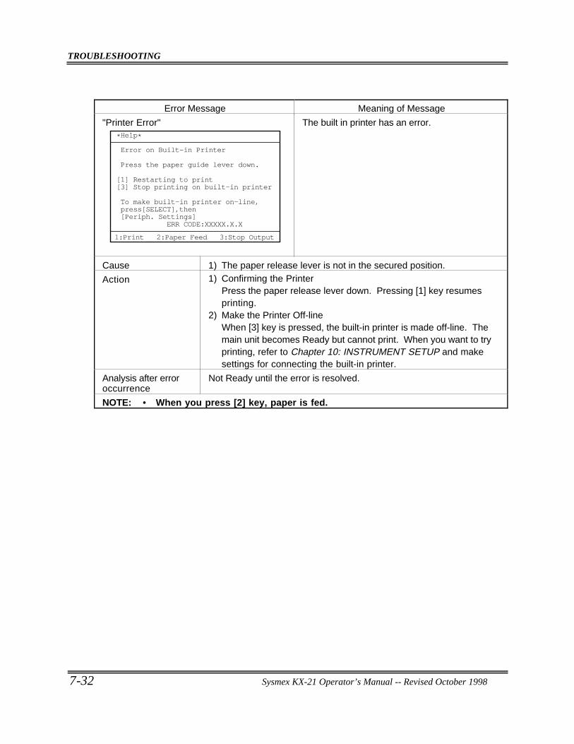
TROUBLESHOOTING
7-32 Sysmex KX-21 Operator’s Manual -- Revised October 1998
Error Message Meaning of Message
"Printer Error"
ERR CODE:XXXXX.X.X
*Help*
Error on Built-in Printer
Press the paper guide lever down.
Restarting to print Stop printing on built-in printer
To make built-in printer on-line,press[SELECT],then[Periph. Settings]
1:Print 2:Paper Feed 3:Stop Output
[1][3]
The built in printer has an error.
Cause 1) The paper release lever is not in the secured position.
Action 1) Confirming the PrinterPress the paper release lever down. Pressing [1] key resumesprinting.
2) Make the Printer Off-lineWhen [3] key is pressed, the built-in printer is made off-line. Themain unit becomes Ready but cannot print. When you want to tryprinting, refer to Chapter 10: INSTRUMENT SETUP and makesettings for connecting the built-in printer.
Analysis after erroroccurrence
Not Ready until the error is resolved.
NOTE: • When you press [2] key, paper is fed.
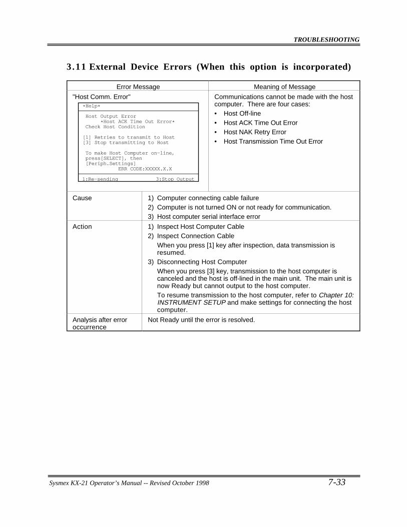
TROUBLESHOOTING
Sysmex KX-21 Operator’s Manual -- Revised October 1998 7-33
3.11 External Device Errors (When this option is incorporated)
Error Message Meaning of Message
"Host Comm. Error"
ERR CODE:XXXXX.X.X
*Help*
Host Output Error *Host ACK Time Out Error*Check Host Condition
Retries to transmit to Host Stop transmitting to Host[1][3]
To make Host Computer on-line,press[SELECT], then[Periph.Settings]
1:Re-sending 3:Stop Output
Communications cannot be made with the hostcomputer. There are four cases:• Host Off-line• Host ACK Time Out Error• Host NAK Retry Error• Host Transmission Time Out Error
Cause 1) Computer connecting cable failure2) Computer is not turned ON or not ready for communication.3) Host computer serial interface error
Action 1) Inspect Host Computer Cable2) Inspect Connection Cable
When you press [1] key after inspection, data transmission isresumed.
3) Disconnecting Host ComputerWhen you press [3] key, transmission to the host computer iscanceled and the host is off-lined in the main unit. The main unit isnow Ready but cannot output to the host computer.To resume transmission to the host computer, refer to Chapter 10:INSTRUMENT SETUP and make settings for connecting the hostcomputer.
Analysis after erroroccurrence
Not Ready until the error is resolved.
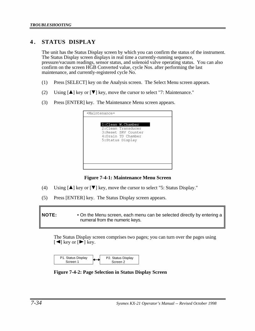
TROUBLESHOOTING
7-34 Sysmex KX-21 Operator’s Manual -- Revised October 1998
4 . STATUS DISPLAY
The unit has the Status Display screen by which you can confirm the status of the instrument.The Status Display screen displays in real time a currently-running sequence,pressure/vacuum readings, sensor status, and solenoid valve operating status. You can alsoconfirm on the screen HGB Converted value, cycle Nos. after performing the lastmaintenance, and currently-registered cycle No.
(1) Press [SELECT] key on the Analysis screen. The Select Menu screen appears.
(2) Using [ ] key or [ ] key, move the cursor to select "7: Maintenance."
(3) Press [ENTER] key. The Maintenance Menu screen appears.
*Maintenance*
1:Clean W.Chamber2:Clean Transducer3:Reset SRV Counter4:Drain TD Chamber5:Status Display
Figure 7-4-1: Maintenance Menu Screen
(4) Using [ ] key or [ ] key, move the cursor to select "5: Status Display."
(5) Press [ENTER] key. The Status Display screen appears.
NOTE: • On the Menu screen, each menu can be selected directly by entering anumeral from the numeric keys.
The Status Display screen comprises two pages; you can turn over the pages using[ ] key or [ ] key.
P1. Status Display Screen 1
P2. Status Display Screen 2
Figure 7-4-2: Page Selection in Status Display Screen
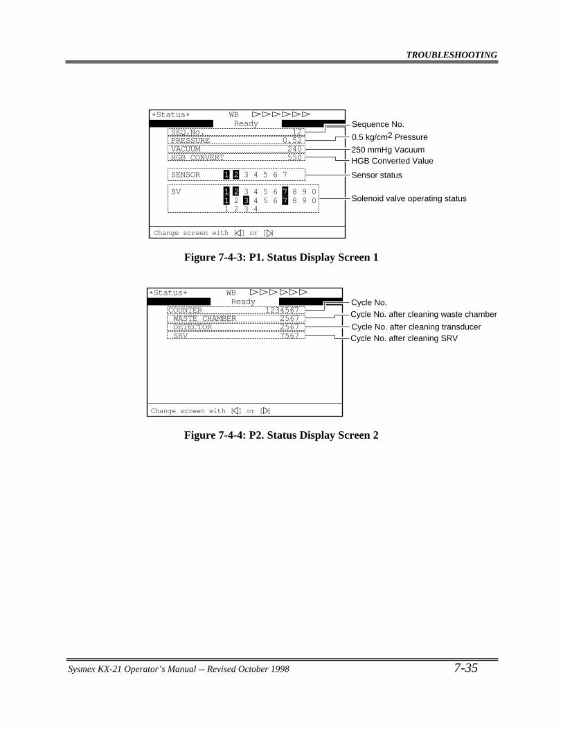
TROUBLESHOOTING
Sysmex KX-21 Operator’s Manual -- Revised October 1998 7-35
SEQ.No. 12
1 2 3 4
SV 1 2 3 4 5 6 7 8 9 0
SENSOR 1 2 3 4 5 6 7
HGB CONVERT 550VACUUM 240
1 2 3 4 5 6 7 8 9 0
PRESSURE 0.52
WB
250 mmHg VacuumHGB Converted Value
Sensor status
Solenoid valve operating status
Change screen with [ ] or [ ]
Ready*Status*
Sequence No.
0.5 kg/cm2 Pressure
Figure 7-4-3: P1. Status Display Screen 1
*Status*
COUNTER 1234567
SRV 7567 DETECTOR 2567 WASTE CHAMBER 2567
WB
Cycle No. after cleaning waste chamberCycle No.
Cycle No. after cleaning transducerCycle No. after cleaning SRV
Change screen with [ ] or [ ]
Ready
Figure 7-4-4: P2. Status Display Screen 2
Sysmex KX-21 Operator’s Manual -- Revised October 1998
CHAPTER 8 ADJUSTMENT
1. INTRODUCTION... . . . . . . . . . . . . . . . . . . . . . . . . . . . . . . . . . . . . . . . . . . . . . . . . . . . . . . . . . . . . . . 8-1
2. ADJUSTMENT OF PRESSURE AND VACUUM... . . . . . . . . . . . . . . . . . . . . . . . . 8-22.1 Location of Control Knobs.. . . . . . . . . . . . . . . . . . . . . . . . . . . . . . . . . . . . . . . . . . . . . . . 8-22.2 Pressure and Vacuum Display .. . . . . . . . . . . . . . . . . . . . . . . . . . . . . . . . . . . . . . . . . . . 8-32.3 Adjusting Pressure to 0.5 kg/cm2 .. . . . . . . . . . . . . . . . . . . . . . . . . . . . . . . . . . . . . . . 8-52.4 Adjusting Vacuum to 250 mmHg ... . . . . . . . . . . . . . . . . . . . . . . . . . . . . . . . . . . . . . 8-6
ADJUSTMENT
Sysmex KX-21 Operator’s Manual -- Revised October 1998 8-1
1 . INTRODUCTION
The adjustment procedures described here are important in maintaining accuracy of thisinstrument. Your Sysmex service representative will perform initial adjustment. Should itrequire any adjustment subsequently, follow the procedures given below.
The following adjustment procedures are explained in this chapter.
• Pressure: 0.5 kg/cm2
• Vacuum: 250 mmHg
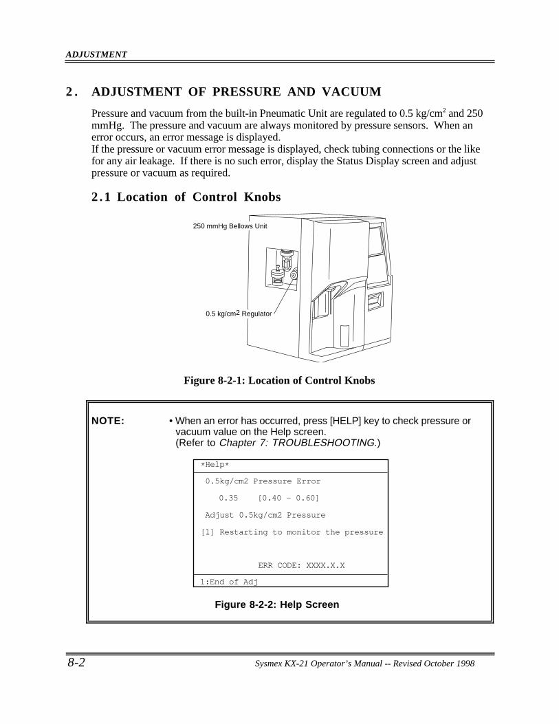
ADJUSTMENT
8-2 Sysmex KX-21 Operator’s Manual -- Revised October 1998
2 . ADJUSTMENT OF PRESSURE AND VACUUM
Pressure and vacuum from the built-in Pneumatic Unit are regulated to 0.5 kg/cm2 and 250mmHg. The pressure and vacuum are always monitored by pressure sensors. When anerror occurs, an error message is displayed.If the pressure or vacuum error message is displayed, check tubing connections or the likefor any air leakage. If there is no such error, display the Status Display screen and adjustpressure or vacuum as required.
2 .1 Location of Control Knobs
0.5 kg/cm2 Regulator
250 mmHg Bellows Unit
Figure 8-2-1: Location of Control Knobs
NOTE: • When an error has occurred, press [HELP] key to check pressure orvacuum value on the Help screen.(Refer to Chapter 7: TROUBLESHOOTING.)
*Help*
0.5kg/cm2 Pressure Error
0.35 [0.40 - 0.60]
ERR CODE: XXXX.X.X
Adjust 0.5kg/cm2 Pressure
Restarting to monitor the pressure[1]
1:End of Adj
Figure 8-2-2: Help Screen
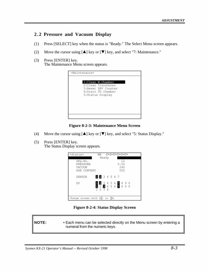
ADJUSTMENT
Sysmex KX-21 Operator’s Manual -- Revised October 1998 8-3
2 .2 Pressure and Vacuum Display
(1) Press [SELECT] key when the status is "Ready." The Select Menu screen appears.
(2) Move the cursor using [ ] key or [ ] key, and select "7: Maintenance."
(3) Press [ENTER] key.The Maintenance Menu screen appears.
*Maintenance*
1:Clean W.Chamber2:Clean Transducer3:Reset SRV Counter4:Drain TD Chamber5:Status Display
Figure 8-2-3: Maintenance Menu Screen
(4) Move the cursor using [ ] key or [ ] key, and select "5: Status Display."
(5) Press [ENTER] key.The Status Display screen appears.
SEQ.No. 12
1 2 3 4
SV 1 2 3 4 5 6 7 8 9 0
SENSOR 1 2 3 4 5 6 7
HGB CONVERT 550VACUUM 240
1 2 3 4 5 6 7 8 9 0
PRESSURE 0.52
WBReady
*Status*
Change screen with [ ] or [ ]
Figure 8-2-4: Status Display Screen
NOTE: • Each menu can be selected directly on the Menu screen by entering anumeral from the numeric keys.
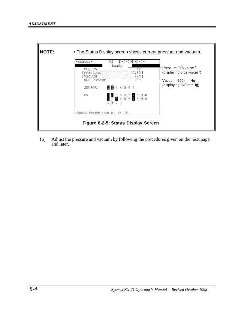
ADJUSTMENT
8-4 Sysmex KX-21 Operator’s Manual -- Revised October 1998
NOTE: • The Status Display screen shows current pressure and vacuum.
SEQ.No. 12
1 2 3 4
SV 1 2 3 4 5 6 7 8 9 0
SENSOR 1 2 3 4 5 6 7
HGB CONVERT 550VACUUM 240
1 2 3 4 5 6 7 8 9 0
PRESSURE 0.52
WBReady
*Status*
Vacuum: 250 mmHg(displaying 240 mmHg)
Pressure: 0.5 kg/cm(displaying 0.52 kg/cm )
2
2
Change screen with [ ] or [ ]
Figure 8-2-5: Status Display Screen
(6) Adjust the pressure and vacuum by following the procedures given on the next pageand later.
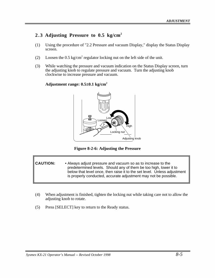
ADJUSTMENT
Sysmex KX-21 Operator’s Manual -- Revised October 1998 8-5
2 .3 Adjusting Pressure to 0.5 kg/cm2
(1) Using the procedure of "2.2 Pressure and vacuum Display," display the Status Displayscreen.
(2) Loosen the 0.5 kg/cm2 regulator locking nut on the left side of the unit.
(3) While watching the pressure and vacuum indication on the Status Display screen, turnthe adjusting knob to regulate pressure and vacuum. Turn the adjusting knobclockwise to increase pressure and vacuum.
Adjustment range: 0.5±0.1 kg/cm2
Low
High
Locking nut
Adjusting knob
Loosen
Figure 8-2-6: Adjusting the Pressure
CAUTION: • Always adjust pressure and vacuum so as to increase to thepredetermined levels. Should any of them be too high, lower it tobelow that level once, then raise it to the set level. Unless adjustmentis properly conducted, accurate adjustment may not be possible.
(4) When adjustment is finished, tighten the locking nut while taking care not to allow theadjusting knob to rotate.
(5) Press [SELECT] key to return to the Ready status.
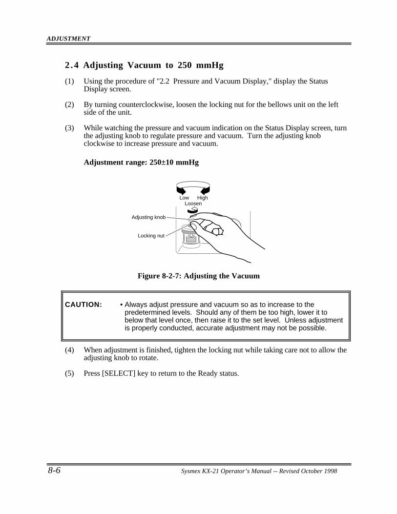
ADJUSTMENT
8-6 Sysmex KX-21 Operator’s Manual -- Revised October 1998
2 .4 Adjusting Vacuum to 250 mmHg
(1) Using the procedure of "2.2 Pressure and Vacuum Display," display the StatusDisplay screen.
(2) By turning counterclockwise, loosen the locking nut for the bellows unit on the leftside of the unit.
(3) While watching the pressure and vacuum indication on the Status Display screen, turnthe adjusting knob to regulate pressure and vacuum. Turn the adjusting knobclockwise to increase pressure and vacuum.
Adjustment range: 250±10 mmHg
HighLow
Locking nut
Adjusting knob
Loosen
Figure 8-2-7: Adjusting the Vacuum
CAUTION: • Always adjust pressure and vacuum so as to increase to thepredetermined levels. Should any of them be too high, lower it tobelow that level once, then raise it to the set level. Unless adjustmentis properly conducted, accurate adjustment may not be possible.
(4) When adjustment is finished, tighten the locking nut while taking care not to allow theadjusting knob to rotate.
(5) Press [SELECT] key to return to the Ready status.
Sysmex KX-21 Operator’s Manual -- Revised October 1998
CHAPTER 9 FUNCTIONAL DESCRIPTION
1. INTRODUCTION ... . . . . . . . . . . . . . . . . . . . . . . . . . . . . . . . . . . . . . . . . . . . . . . . . . . . . . . . . . . . . . . 9-1
2. DETECTION PRINCIPLE ... . . . . . . . . . . . . . . . . . . . . . . . . . . . . . . . . . . . . . . . . . . . . . . . . . . . .9-22.1 DC Detection Method.. . . . . . . . . . . . . . . . . . . . . . . . . . . . . . . . . . . . . . . . . . . . . . . . . . . . . .9-22.2 Non-Cyanide Hemoglobin Analysis Method .. . . . . . . . . . . . . . . . . . . . . . . . . . .9-2
3. MEASURING UNIT HYDRAULIC SYSTEM BLOCK DIAGRAM .. . . . .9-4
4. CBC ANALYSIS ... . . . . . . . . . . . . . . . . . . . . . . . . . . . . . . . . . . . . . . . . . . . . . . . . . . . . . . . . . . . . . . .9-54.1 WBC/HGB Analysis Flow ... . . . . . . . . . . . . . . . . . . . . . . . . . . . . . . . . . . . . . . . . . . . . .9-54.2 RBC/PLT Analysis Flow ... . . . . . . . . . . . . . . . . . . . . . . . . . . . . . . . . . . . . . . . . . . . . . . .9-74.3 Calculation of RBC Constant. . . . . . . . . . . . . . . . . . . . . . . . . . . . . . . . . . . . . . . . . . . . . .9-9
5. BLOOD CELL DISCRIMINATION CIRCUIT... . . . . . . . . . . . . . . . . . . . . . . . . . . . 9-105.1 WBC Discriminator.. . . . . . . . . . . . . . . . . . . . . . . . . . . . . . . . . . . . . . . . . . . . . . . . . . . . . . 9-105.2 RBC Discriminator.. . . . . . . . . . . . . . . . . . . . . . . . . . . . . . . . . . . . . . . . . . . . . . . . . . . . . . . 9-105.3 PLT Discriminator .. . . . . . . . . . . . . . . . . . . . . . . . . . . . . . . . . . . . . . . . . . . . . . . . . . . . . . . 9-10
6. ANALYSIS OF HISTOGRAM ... . . . . . . . . . . . . . . . . . . . . . . . . . . . . . . . . . . . . . . . . . . . . . 9-116.1 Analysis of WBC Histogram ... . . . . . . . . . . . . . . . . . . . . . . . . . . . . . . . . . . . . . . . . . 9-116.2 Analysis of RBC/PLT Histogram... . . . . . . . . . . . . . . . . . . . . . . . . . . . . . . . . . . . . 9-20
7. ELECTRIC SYSTEM ... . . . . . . . . . . . . . . . . . . . . . . . . . . . . . . . . . . . . . . . . . . . . . . . . . . . . . . . . 9-28
8. NAMES AND FUNCTIONS OF INSTRUMENTS ... . . . . . . . . . . . . . . . . . . . . . 9-308.1 Front Panel.. . . . . . . . . . . . . . . . . . . . . . . . . . . . . . . . . . . . . . . . . . . . . . . . . . . . . . . . . . . . . . . . 9-308.2 Front Interior . . . . . . . . . . . . . . . . . . . . . . . . . . . . . . . . . . . . . . . . . . . . . . . . . . . . . . . . . . . . . . 9-318.3 Right Side Panel. . . . . . . . . . . . . . . . . . . . . . . . . . . . . . . . . . . . . . . . . . . . . . . . . . . . . . . . . . . 9-328.4 Left Side Panel . . . . . . . . . . . . . . . . . . . . . . . . . . . . . . . . . . . . . . . . . . . . . . . . . . . . . . . . . . . . 9-338.5 Left Side Interior . . . . . . . . . . . . . . . . . . . . . . . . . . . . . . . . . . . . . . . . . . . . . . . . . . . . . . . . . . 9-348.6 Rear Panel.. . . . . . . . . . . . . . . . . . . . . . . . . . . . . . . . . . . . . . . . . . . . . . . . . . . . . . . . . . . . . . . . . 9-35
FUNCTIONAL DESCRIPTION
Sysmex KX-21 Operator’s Manual -- Revised October 1998 9-1
1 . INTRODUCTION
This chapter describes blood cell count detection principle and analysis method used in thisinstrument, and flow of individual analysis. Also the hardware elements are explained.
• Detection Principle: Principle each of DC detection method and non-cyanide hemoglobin analysis method is described.
• Flow of Analysis: Flow of each analysis parameter on the main unit and analysis method for particle distribution are described.
• Function of Measuring Unit: Names and functions of the measuring unit's elements are briefly described.

FUNCTIONAL DESCRIPTION
9-2 Sysmex KX-21 Operator’s Manual -- Revised October 1998
2 . DETECTION PRINCIPLE
This instrument performs blood cell count by DC detection method.
2 .1 DC Detection Method
Blood sample is aspirated, measured to a predetermined volume, diluted at the specifiedratio, then fed into each transducer. The transducer chamber has a minute hole called theaperture. On both side of the aperture, there are the electrodes between which flows directcurrent. Blood cells suspended in the diluted sample pass through the aperture, causingdirect current resistance to change between the electrodes. As direct current resistancechanges, the blood cell size is detected as electric pulses.Blood cell count is calculated by counting the pulses, and a histogram of blood cell sizes isplotted by determining the pulse sizes. Also, analyzing a histogram makes it possible toobtain various analysis data.
Internal Electrode -
External Electrode +
Blood Cell Suspension
Aperture
DC Supply
Resistance
DC
Transducer Chamber
Figure 9-2-1: DC Detection Method
2 .2 Non-Cyanide Hemoglobin Analysis Method
To analyze hemoglobin by automated methods, the Cyanmethemoglobin method orOxyhemoglobin method have so far been the main stream.Cyanmethemoglobin method was recommended as the international standard method in 1966by ICSH (International Committee for Standardization in Haematology). This method,however, is so low in hemoglobin conversion rate that it cannot be said an appropriatemethod in the automated process in which multi-sample processing is the pre-condition. Inaddition, this method uses the reagent of cyanide compound which is a poisonous substanceand requires waste processing; thus, it can hardly be called an environmentally favorablemethod.At present, this method cannot be said suitable for a fully-automated instrument which isrequired to handle a large amount of waste.
FUNCTIONAL DESCRIPTION
Sysmex KX-21 Operator’s Manual -- Revised October 1998 9-3
The Oxyhemoglobin method, on the other hand, is faster in hemoglobin conversion rate; infact, blood hemoglobin is converted instantaneously into oxyhemoglobin. Also, it does notcontain poisonous substance as cyanmethemoglobin method, making the method suitable forautomation. This method, however, is unable to convert methemoglobin intooxyhemoglobin. Consequently, when a great amount of methemoglobin is contained as incontrol blood, lower-than-real values result, although usual human blood poses noproblems.
Non-cyanide hemoglobin analysis method utilizes the advantages of both of the abovemethods. Non-cyanide hemoglobin analysis method rapidly converts blood hemoglobin asthe Oxyhemoglobin method and contains no poisonous substance, making it suitable forautomated method.Being capable of analyzing methemoglobin, this method can accurately analyze controlblood, etc. which contain methemoglobin.
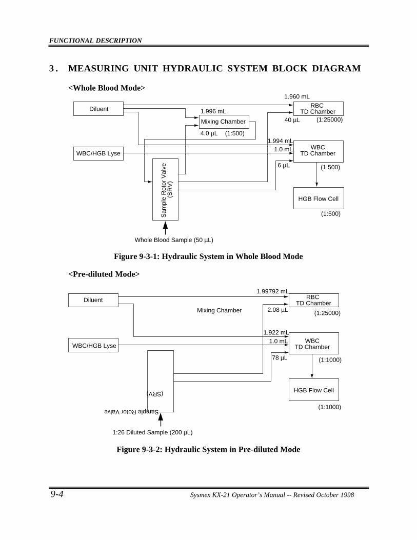
FUNCTIONAL DESCRIPTION
9-4 Sysmex KX-21 Operator’s Manual -- Revised October 1998
3 . MEASURING UNIT HYDRAULIC SYSTEM BLOCK DIAGRAM
<Whole Blood Mode>
Sam
ple
Rot
or V
alve
(S
RV
)
Diluent
WBC/HGB Lyse
1.996 mL
1.960 mL
1.994 mL1.0 mL
4.0 µL (1:500)
6 µL
40 µL (1:25000)
(1:500)
(1:500)
Whole Blood Sample (50 µL)
Mixing Chamber
RBC TD Chamber
WBC TD Chamber
HGB Flow Cell
Figure 9-3-1: Hydraulic System in Whole Blood Mode
<Pre-diluted Mode>
1.99792 mL
2.08 µL
1.922 mL
78 µL
1.0 mL
Sample Rotor Valve
(SRV)
Diluent
WBC/HGB Lyse
(1:1000)
(1:1000)
(1:25000)
1:26 Diluted Sample (200 µL)
Mixing Chamber
RBC TD Chamber
WBC TD Chamber
HGB Flow Cell
Figure 9-3-2: Hydraulic System in Pre-diluted Mode
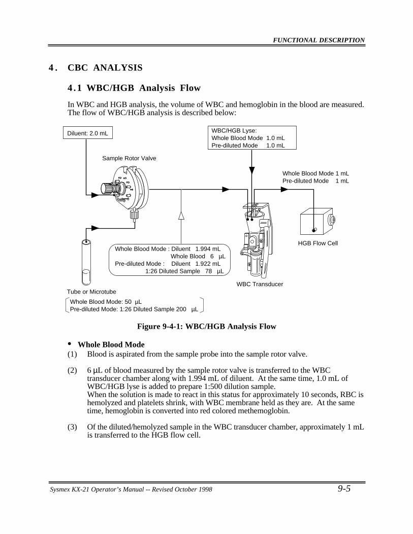
FUNCTIONAL DESCRIPTION
Sysmex KX-21 Operator’s Manual -- Revised October 1998 9-5
4 . CBC ANALYSIS
4 .1 WBC/HGB Analysis Flow
In WBC and HGB analysis, the volume of WBC and hemoglobin in the blood are measured.The flow of WBC/HGB analysis is described below:
WBC Transducer
Sample Rotor Valve
Whole Blood Mode : Diluent 1.994 mL Whole Blood 6 µLPre-diluted Mode : Diluent 1.922 mL 1:26 Diluted Sample 78 µL
Whole Blood Mode 1 mLPre-diluted Mode 1 mL
WBC/HGB Lyse:Whole Blood Mode 1.0 mLPre-diluted Mode 1.0 mL
HGB Flow Cell
Tube or Microtube
Whole Blood Mode: 50 µLPre-diluted Mode: 1:26 Diluted Sample 200 µL
Diluent: 2.0 mL
Figure 9-4-1: WBC/HGB Analysis Flow
• Whole Blood Mode(1) Blood is aspirated from the sample probe into the sample rotor valve.
(2) 6 µL of blood measured by the sample rotor valve is transferred to the WBCtransducer chamber along with 1.994 mL of diluent. At the same time, 1.0 mL ofWBC/HGB lyse is added to prepare 1:500 dilution sample.When the solution is made to react in this status for approximately 10 seconds, RBC ishemolyzed and platelets shrink, with WBC membrane held as they are. At the sametime, hemoglobin is converted into red colored methemoglobin.
(3) Of the diluted/hemolyzed sample in the WBC transducer chamber, approximately 1 mLis transferred to the HGB flow cell.
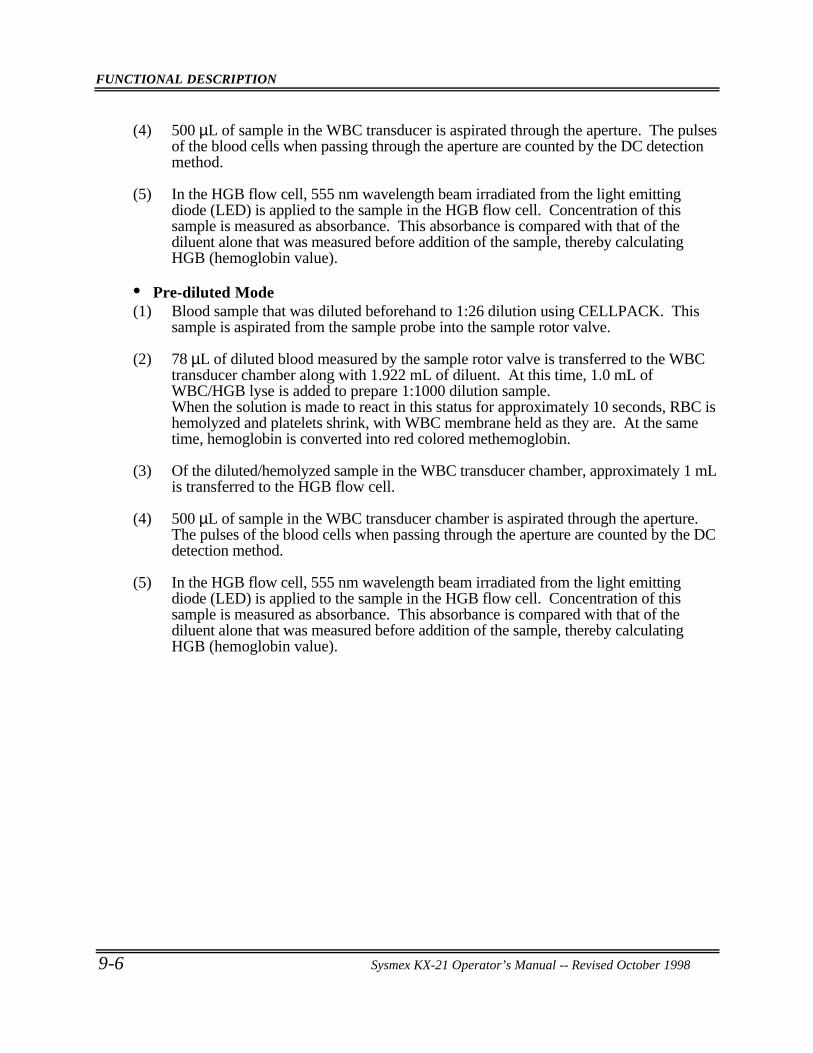
FUNCTIONAL DESCRIPTION
9-6 Sysmex KX-21 Operator’s Manual -- Revised October 1998
(4) 500 µL of sample in the WBC transducer is aspirated through the aperture. The pulsesof the blood cells when passing through the aperture are counted by the DC detectionmethod.
(5) In the HGB flow cell, 555 nm wavelength beam irradiated from the light emittingdiode (LED) is applied to the sample in the HGB flow cell. Concentration of thissample is measured as absorbance. This absorbance is compared with that of thediluent alone that was measured before addition of the sample, thereby calculatingHGB (hemoglobin value).
• Pre-diluted Mode(1) Blood sample that was diluted beforehand to 1:26 dilution using CELLPACK. This
sample is aspirated from the sample probe into the sample rotor valve.
(2) 78 µL of diluted blood measured by the sample rotor valve is transferred to the WBCtransducer chamber along with 1.922 mL of diluent. At this time, 1.0 mL ofWBC/HGB lyse is added to prepare 1:1000 dilution sample.When the solution is made to react in this status for approximately 10 seconds, RBC ishemolyzed and platelets shrink, with WBC membrane held as they are. At the sametime, hemoglobin is converted into red colored methemoglobin.
(3) Of the diluted/hemolyzed sample in the WBC transducer chamber, approximately 1 mLis transferred to the HGB flow cell.
(4) 500 µL of sample in the WBC transducer chamber is aspirated through the aperture.The pulses of the blood cells when passing through the aperture are counted by the DCdetection method.
(5) In the HGB flow cell, 555 nm wavelength beam irradiated from the light emittingdiode (LED) is applied to the sample in the HGB flow cell. Concentration of thissample is measured as absorbance. This absorbance is compared with that of thediluent alone that was measured before addition of the sample, thereby calculatingHGB (hemoglobin value).
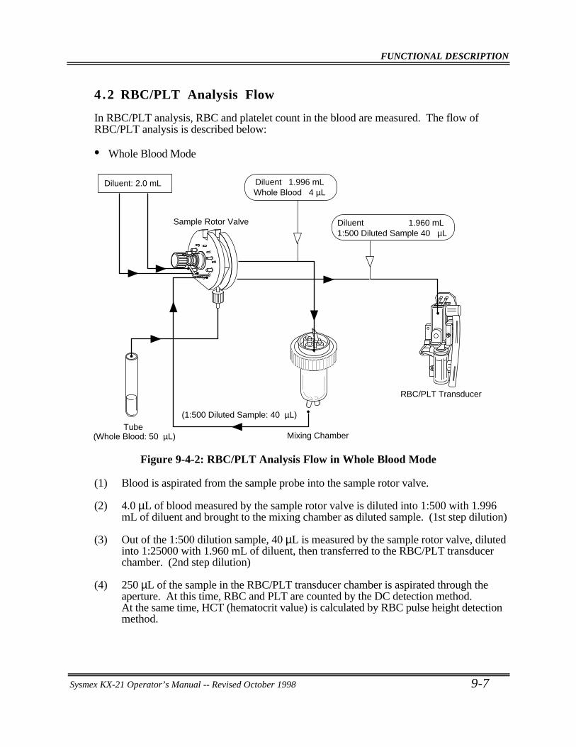
FUNCTIONAL DESCRIPTION
Sysmex KX-21 Operator’s Manual -- Revised October 1998 9-7
4 .2 RBC/PLT Analysis Flow
In RBC/PLT analysis, RBC and platelet count in the blood are measured. The flow ofRBC/PLT analysis is described below:
• Whole Blood Mode
Mixing Chamber
(1:500 Diluted Sample: 40 µL)Tube
(Whole Blood: 50 µL)
Sample Rotor Valve
Diluent: 2.0 mL Diluent 1.996 mLWhole Blood 4 µL
Diluent 1.960 mL1:500 Diluted Sample 40 µL
RBC/PLT Transducer
Figure 9-4-2: RBC/PLT Analysis Flow in Whole Blood Mode
(1) Blood is aspirated from the sample probe into the sample rotor valve.
(2) 4.0 µL of blood measured by the sample rotor valve is diluted into 1:500 with 1.996mL of diluent and brought to the mixing chamber as diluted sample. (1st step dilution)
(3) Out of the 1:500 dilution sample, 40 µL is measured by the sample rotor valve, dilutedinto 1:25000 with 1.960 mL of diluent, then transferred to the RBC/PLT transducerchamber. (2nd step dilution)
(4) 250 µL of the sample in the RBC/PLT transducer chamber is aspirated through theaperture. At this time, RBC and PLT are counted by the DC detection method.At the same time, HCT (hematocrit value) is calculated by RBC pulse height detectionmethod.
FUNCTIONAL DESCRIPTION
9-8 Sysmex KX-21 Operator’s Manual -- Revised October 1998
• Pre-diluted Mode
Microtube (1:26 Diluted Sample: 200 µL)
RBC/PLT Transducer
Diluent 1.99792 mL1:26 Diluted Sample 2.08 µL
Sample Rotor Valve
Diluent : 2.0 mL
Figure 9-4-3: RBC/PLT Analysis Flow in Pre-diluted Mode
(1) Blood sample that was diluted beforehand to 1:26 dilution using CELLPACK. Thissample is aspirated from the sample probe into the sample rotor valve.
(2) 2.08 µL of diluted blood measured by the sample rotor valve is transferred in 1.99792mL of diluent to the RBC/PLT transducer chamber, and is made into 1:25000 dilutionsample.
(3) Of the sample in the RBC/PLT transducer chamber, 250 µL is aspirated through theaperture. At this time, RBC and PLT are calculated by the DC detection method. Atthe same time, HCT (hematocrit value) is calculated by RBC pulse height detectionmethod.
FUNCTIONAL DESCRIPTION
Sysmex KX-21 Operator’s Manual -- Revised October 1998 9-9
4 .3 Calculation of RBC Constant
RBC constant (mean RBC volume, mean RBC hemoglobin, mean RBC hemoglobinconcentration) is calculated from RBC, HGB, and HCT.
1. Mean RBC Volume (MCV)Calculation is made from RBC and HCT by the formula below:
MCV (fL) =HCT (%)
RBC (×106/µL)×10
2. Mean RBC Hemoglobin (MCH)Calculation is made from RBC and HGB by the formula below:
MCH (pg) =HGB (g/dL)
RBC (×106/µL)×10
3. Mean RBC Hemoglobin Concentration (MCHC)Calculation is made from HCT and HGB by the formula below:
MCHC (g/dL) =HGB (g/dL)
HCT (%)×100
FUNCTIONAL DESCRIPTION
9-10 Sysmex KX-21 Operator’s Manual -- Revised October 1998
5 . BLOOD CELL DISCRIMINATION CIRCUIT
WBC, RBC, and PLT are discriminated and calculated by the following blood celldiscriminator.
5 .1 WBC Discriminator
As to WBC LOWER discriminator, the optimum position in 30 - 60 fL is automaticallydetermined by the microcomputer. WBC is calculated from the particle counts more than thisLOWER discriminator.
5 .2 RBC Discriminator
As to RBC LOWER discriminator and UPPER discriminator, the optimum position in 25 -75 fL and 200 - 250 fL, respectively, are automatically determined by the microcomputer.RBC is calculated from the particle counts between this LOWER discriminator and UPPERdiscriminator.
5 .3 PLT Discriminator
As to PLT LOWER discriminator and UPPER discriminator, the optimum position in 2 - 6fL and 12 - 30 fL, respectively, are automatically determined by the microcomputer. PLTcount is calculated from the particle counts between this LOWER discriminator and UPPERdiscriminator.
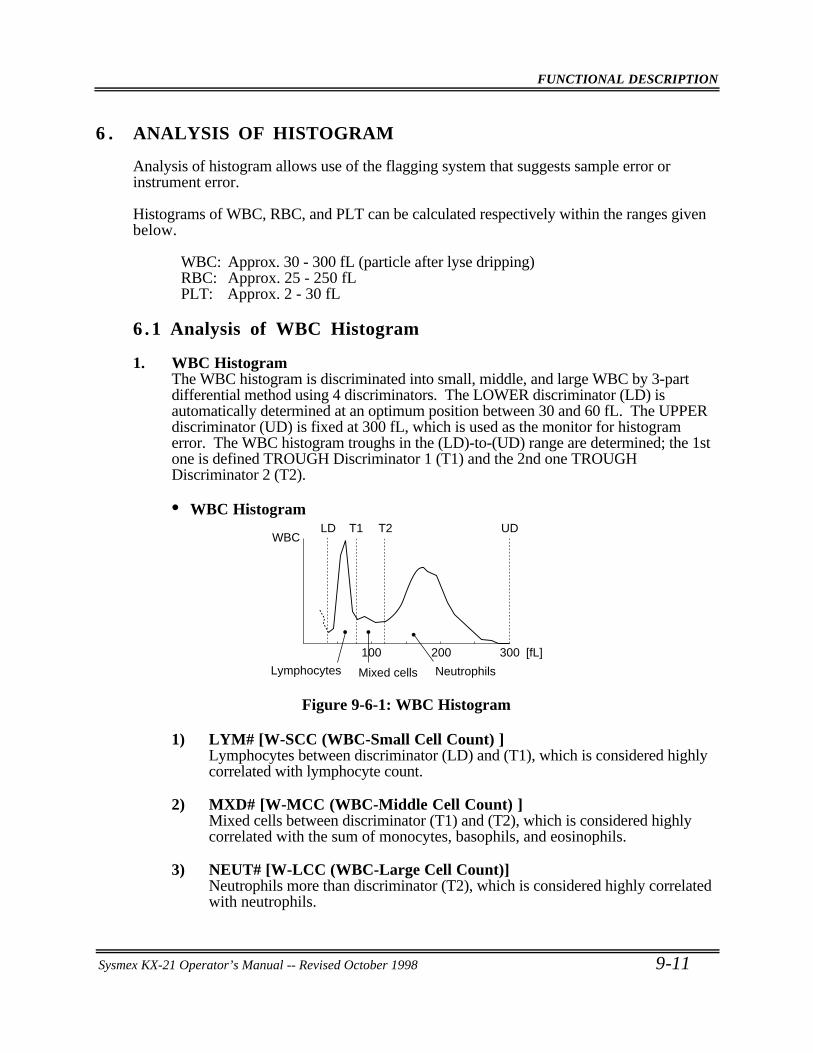
FUNCTIONAL DESCRIPTION
Sysmex KX-21 Operator’s Manual -- Revised October 1998 9-11
6 . ANALYSIS OF HISTOGRAM
Analysis of histogram allows use of the flagging system that suggests sample error orinstrument error.
Histograms of WBC, RBC, and PLT can be calculated respectively within the ranges givenbelow.
WBC: Approx. 30 - 300 fL (particle after lyse dripping)RBC: Approx. 25 - 250 fLPLT: Approx. 2 - 30 fL
6 .1 Analysis of WBC Histogram
1. WBC HistogramThe WBC histogram is discriminated into small, middle, and large WBC by 3-partdifferential method using 4 discriminators. The LOWER discriminator (LD) isautomatically determined at an optimum position between 30 and 60 fL. The UPPERdiscriminator (UD) is fixed at 300 fL, which is used as the monitor for histogramerror. The WBC histogram troughs in the (LD)-to-(UD) range are determined; the 1stone is defined TROUGH Discriminator 1 (T1) and the 2nd one TROUGHDiscriminator 2 (T2).
• WBC Histogram
300
WBCUD
Lymphocytes Mixed cells Neutrophils
200100
LD T1 T2
[fL]
Figure 9-6-1: WBC Histogram
1) LYM# [W-SCC (WBC-Small Cell Count) ]Lymphocytes between discriminator (LD) and (T1), which is considered highlycorrelated with lymphocyte count.
2) MXD# [W-MCC (WBC-Middle Cell Count) ]Mixed cells between discriminator (T1) and (T2), which is considered highlycorrelated with the sum of monocytes, basophils, and eosinophils.
3) NEUT# [W-LCC (WBC-Large Cell Count)]Neutrophils more than discriminator (T2), which is considered highly correlatedwith neutrophils.
FUNCTIONAL DESCRIPTION
9-12 Sysmex KX-21 Operator’s Manual -- Revised October 1998
4) LYM% [W-SCR (WBC-Small Cell Ratio) ]Ratio of lymphocytes to whole WBC
5) MXD% [W-MCR (WBC-Middle Cell Ratio) ]Ratio of mixed cells to whole WBC
6) NEUT% [W-LCR (WBC-Large Cell Ratio) ]Ratio of neutrophils to whole WBC
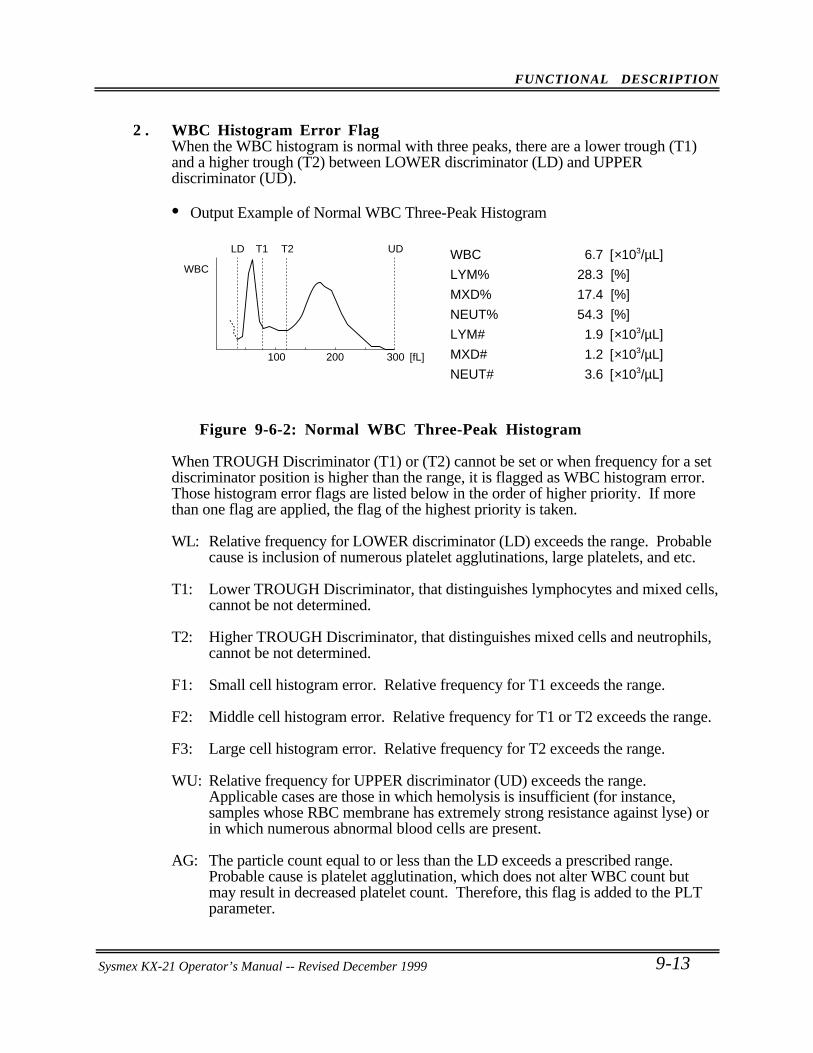
FUNCTIONAL DESCRIPTION
Sysmex KX-21 Operator’s Manual -- Revised October 1998 9-13
2 . WBC Histogram Error FlagWhen the WBC histogram is normal with three peaks, there are a lower trough (T1)and a higher trough (T2) between LOWER discriminator (LD) and UPPERdiscriminator (UD).
• Output Example of Normal WBC Three-Peak Histogram
300
WBC
UD
200100
LD T1 T2
[fL]
WBC
LYM%
MXD%
NEUT%
LYM#
MXD#
NEUT#
6.7
28.3
17.4
54.3
1.9
1.2
3.6
[×103/µL]
[%]
[%]
[%]
[×103/µL]
[×103/µL]
[×103/µL]
Figure 9-6-2: Normal WBC Three-Peak Histogram
When TROUGH Discriminator (T1) or (T2) cannot be set or when frequency for a setdiscriminator position is higher than the range, it is flagged as WBC histogram error.Those histogram error flags are listed below in the order of higher priority. If morethan one flag are applied, the flag of the highest priority is taken.
WL: Relative frequency for LOWER discriminator (LD) exceeds the range. Probablecause is inclusion of numerous platelet agglutinations, large platelets, and etc.
T1: Lower TROUGH Discriminator, that distinguishes lymphocytes and mixed cells,cannot be not determined.
T2: Higher TROUGH Discriminator, that distinguishes mixed cells and neutrophils,cannot be not determined.
F1: Small cell histogram error. Relative frequency for T1 exceeds the range.
F2: Middle cell histogram error. Relative frequency for T1 or T2 exceeds the range.
F3: Large cell histogram error. Relative frequency for T2 exceeds the range.
WU: Relative frequency for UPPER discriminator (UD) exceeds the range.Applicable cases are those in which hemolysis is insufficient (for instance,samples whose RBC membrane has extremely strong resistance against lyse) orin which numerous abnormal blood cells are present.
AG: The particle count equal to or less than the LD exceeds a prescribed range.Probable cause is platelet agglutination, which does not alter WBC count butmay result in decreased platelet count. Therefore, this flag is added to the PLTparameter.
Sysmex KX-21 Operator’s Manual -- Revised December 1999
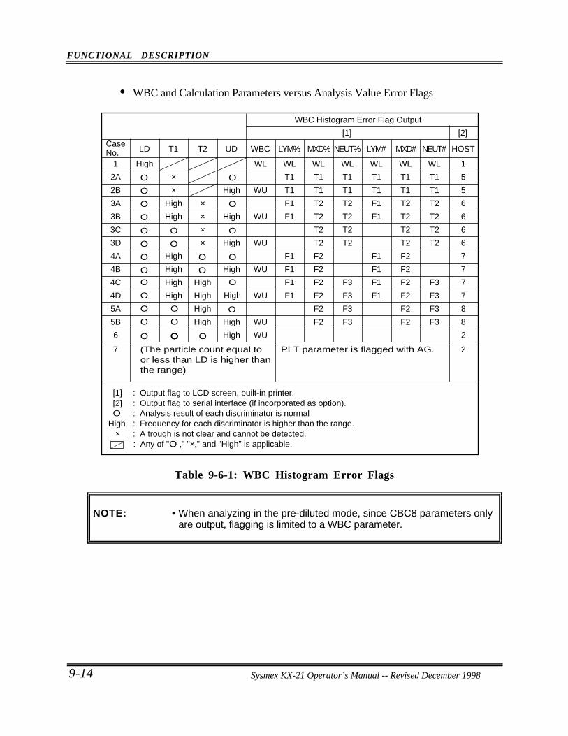
FUNCTIONAL DESCRIPTION
9-14 Sysmex KX-21 Operator’s Manual -- Revised October 1998
• WBC and Calculation Parameters versus Analysis Value Error Flags
O
WBC Histogram Error Flag Output
[1] [2]
[1] : Output flag to LCD screen, built-in printer. [2] : Output flag to serial interface (if incorporated as option). O : Analysis result of each discriminator is normal High : Frequency for each discriminator is higher than the range. × : A trough is not clear and cannot be detected. : Any of "O ," "×," and "High" is applicable.
Case No. LD T1 T2 UD WBC LYM% MXD% NEUT% LYM# MXD# NEUT# HOST
1
2A
2B
3A
3B
3C
3D
4A
4B
4C
4D
5A
5B
6
High
O
O
O
O
O
O
O
O
O
O
O
OO
O
O
O
O
O
O
OO
O
O
O
O
OO O
××
High
High
High
High
High
High
××××
High
High
High
High
High
High
High
High
High
High
High
WL
WU
WU
WU
WU
WU
WU
WU
WL
T1
T1
F1
F1
F1
F1
F1
F1
WL
T1
T1
T2
T2
T2
T2
F2
F2
F2
F2
F2
F2
WL
T1
T1
T2
T2
T2
T2
F3
F3
F3
F3
WL
T1
T1
F1
F1
F1
F1
F1
F1
WL
T1
T1
T2
T2
T2
T2
F2
F2
F2
F2
F2
F2
WL
T1
T1
T2
T2
T2
T2
F3
F3
F3
F3
1
5
5
6
6
6
6
7
7
7
7
8
8
2
7 (The particle count equal to or less than LD is higher thanthe range)
PLT parameter is flagged with AG. 2
Table 9-6-1: WBC Histogram Error Flags
NOTE: • When analyzing in the pre-diluted mode, since CBC8 parameters onlyare output, flagging is limited to a WBC parameter.
Sysmex KX-21 Operator’s Manual -- Revised December 1998
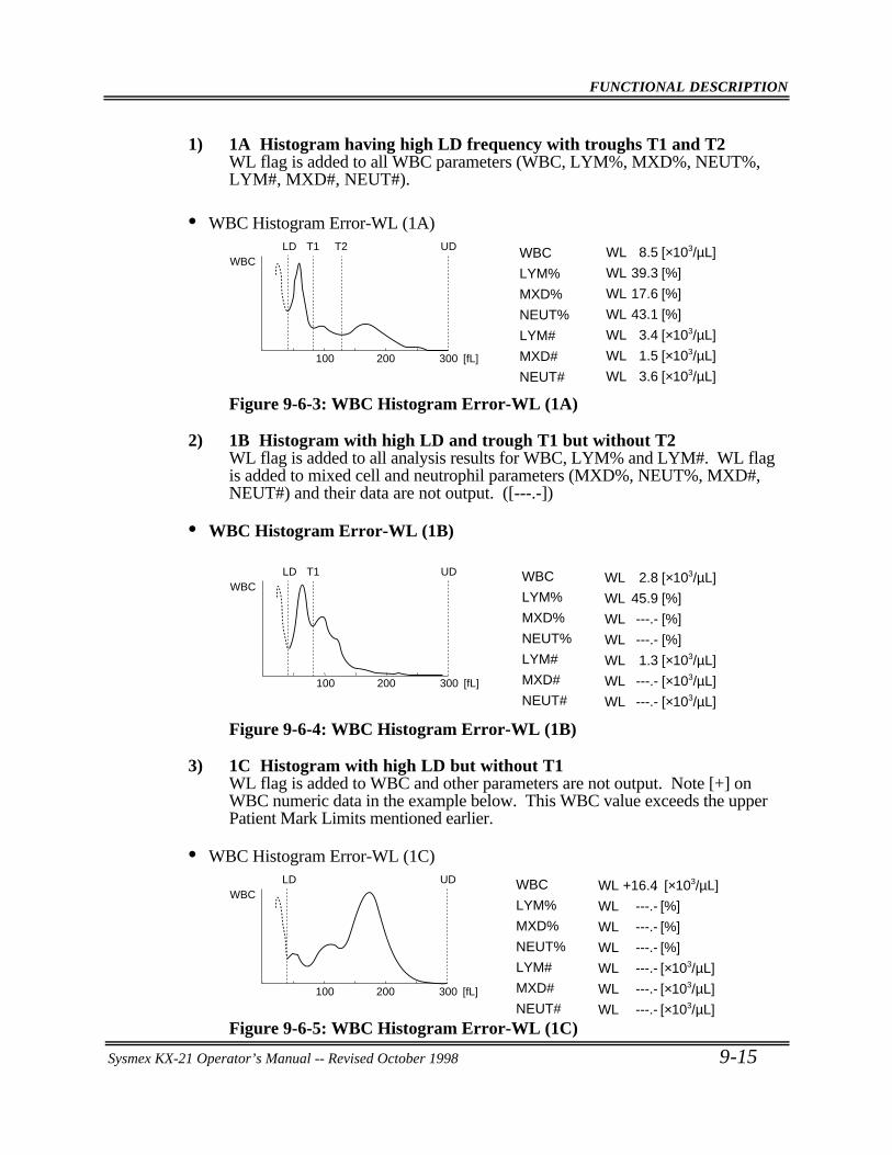
FUNCTIONAL DESCRIPTION
Sysmex KX-21 Operator’s Manual -- Revised October 1998 9-15
1) 1A Histogram having high LD frequency with troughs T1 and T2WL flag is added to all WBC parameters (WBC, LYM%, MXD%, NEUT%,LYM#, MXD#, NEUT#).
• WBC Histogram Error-WL (1A)
WBCUDLD T1 T2 8.5
39.3
17.6
43.1
3.4
1.5
3.6
[×103/µL]
[%]
[%]
[%]
[×103/µL]
[×103/µL]
[×103/µL]300200100 [fL]
WL
WL
WL
WL
WL
WL
WL
WBC
LYM%
MXD%
NEUT%
LYM#
MXD#
NEUT#
Figure 9-6-3: WBC Histogram Error-WL (1A)
2) 1B Histogram with high LD and trough T1 but without T2WL flag is added to all analysis results for WBC, LYM% and LYM#. WL flagis added to mixed cell and neutrophil parameters (MXD%, NEUT%, MXD#,NEUT#) and their data are not output. ([---.-])
• WBC Histogram Error-WL (1B)
WL
WL
WL
WL
WL
WL
WL
WBCUDLD T1 2.8
45.9
---.-
---.-
1.3
---.-
---.-
[×103/µL]
[%]
[%]
[%]
[×103/µL]
[×103/µL]
[×103/µL]300200100 [fL]
WBC
LYM%
MXD%
NEUT%
LYM#
MXD#
NEUT#
Figure 9-6-4: WBC Histogram Error-WL (1B)
3) 1C Histogram with high LD but without T1WL flag is added to WBC and other parameters are not output. Note [+] onWBC numeric data in the example below. This WBC value exceeds the upperPatient Mark Limits mentioned earlier.
• WBC Histogram Error-WL (1C)
WL
WL
WL
WL
WL
WL
WL
WBCUD +16.4
---.-
---.-
---.-
---.-
---.-
---.-
LD . [×103/µL]
[%]
[%]
[%]
[×103/µL]
[×103/µL]
[×103/µL]300200100 [fL]
WBC
LYM%
MXD%
NEUT%
LYM#
MXD#
NEUT#
Figure 9-6-5: WBC Histogram Error-WL (1C)
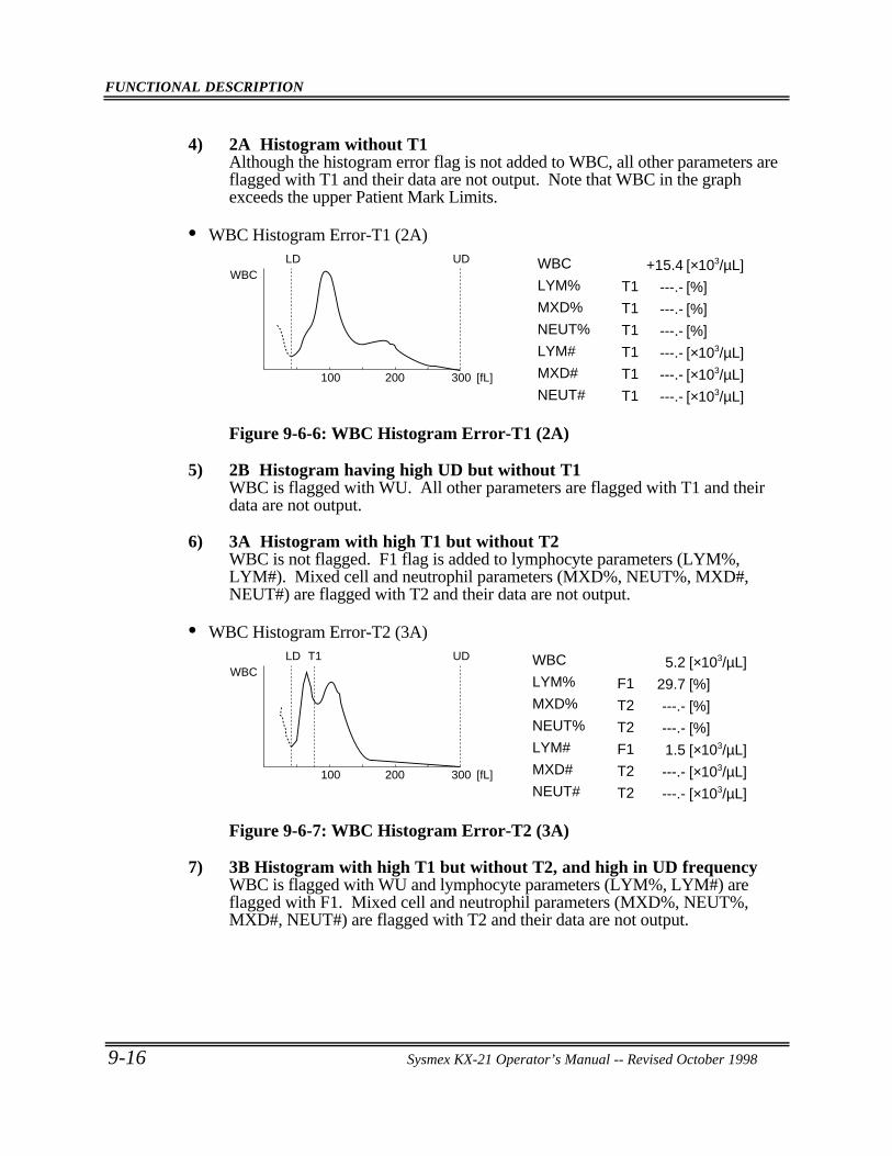
FUNCTIONAL DESCRIPTION
9-16 Sysmex KX-21 Operator’s Manual -- Revised October 1998
4) 2A Histogram without T1Although the histogram error flag is not added to WBC, all other parameters areflagged with T1 and their data are not output. Note that WBC in the graphexceeds the upper Patient Mark Limits.
• WBC Histogram Error-T1 (2A)
WBCUDLD +15.4
---.-
---.-
---.-
---.-
---.-
---.-
[×103/µL]
[%]
[%]
[%]
[×103/µL]
[×103/µL]
[×103/µL]300200100 [fL]
T1
T1
T1
T1
T1
T1
WBC
LYM%
MXD%
NEUT%
LYM#
MXD#
NEUT#
Figure 9-6-6: WBC Histogram Error-T1 (2A)
5) 2B Histogram having high UD but without T1WBC is flagged with WU. All other parameters are flagged with T1 and theirdata are not output.
6) 3A Histogram with high T1 but without T2WBC is not flagged. F1 flag is added to lymphocyte parameters (LYM%,LYM#). Mixed cell and neutrophil parameters (MXD%, NEUT%, MXD#,NEUT#) are flagged with T2 and their data are not output.
• WBC Histogram Error-T2 (3A)
WBCUDLD T1 5.2
29.7
---.-
---.-
1.5
---.-
---.-
[×103/µL]
[%]
[%]
[%]
[×103/µL]
[×103/µL]
[×103/µL]300200100 [fL]
F1
T2
T2
F1
T2
T2
WBC
LYM%
MXD%
NEUT%
LYM#
MXD#
NEUT#
Figure 9-6-7: WBC Histogram Error-T2 (3A)
7) 3B Histogram with high T1 but without T2, and high in UD frequencyWBC is flagged with WU and lymphocyte parameters (LYM%, LYM#) areflagged with F1. Mixed cell and neutrophil parameters (MXD%, NEUT%,MXD#, NEUT#) are flagged with T2 and their data are not output.
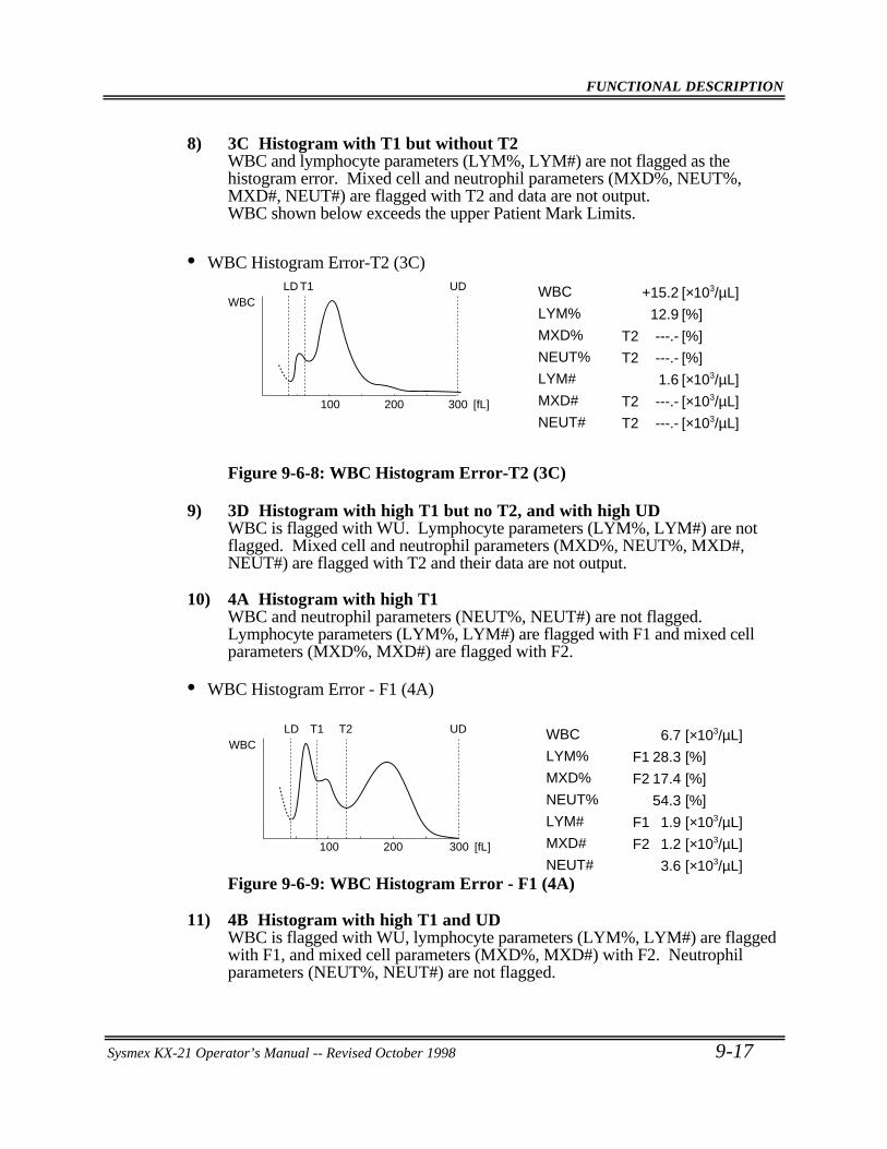
FUNCTIONAL DESCRIPTION
Sysmex KX-21 Operator’s Manual -- Revised October 1998 9-17
8) 3C Histogram with T1 but without T2WBC and lymphocyte parameters (LYM%, LYM#) are not flagged as thehistogram error. Mixed cell and neutrophil parameters (MXD%, NEUT%,MXD#, NEUT#) are flagged with T2 and data are not output.WBC shown below exceeds the upper Patient Mark Limits.
• WBC Histogram Error-T2 (3C)
300
WBCUDLD T1
[fL]
+15.2
12.9
---.-
---.-
1.6
---.-
---.-
[×103/µL]
[%]
[%]
[%]
[×103/µL]
[×103/µL]
[×103/µL]200100
T2
T2
T2
T2
WBC
LYM%
MXD%
NEUT%
LYM#
MXD#
NEUT#
Figure 9-6-8: WBC Histogram Error-T2 (3C)
9) 3D Histogram with high T1 but no T2, and with high UDWBC is flagged with WU. Lymphocyte parameters (LYM%, LYM#) are notflagged. Mixed cell and neutrophil parameters (MXD%, NEUT%, MXD#,NEUT#) are flagged with T2 and their data are not output.
10) 4A Histogram with high T1WBC and neutrophil parameters (NEUT%, NEUT#) are not flagged.Lymphocyte parameters (LYM%, LYM#) are flagged with F1 and mixed cellparameters (MXD%, MXD#) are flagged with F2.
• WBC Histogram Error - F1 (4A)
WBCLD T1 T2 6.7
28.3
17.4
54.3
1.9
1.2
3.6
UD [×103/µL]
[%]
[%]
[%]
[×103/µL]
[×103/µL]
[×103/µL]300200100 [fL]
F1
F2
F1
F2
WBC
LYM%
MXD%
NEUT%
LYM#
MXD#
NEUT#Figure 9-6-9: WBC Histogram Error - F1 (4A)
11) 4B Histogram with high T1 and UDWBC is flagged with WU, lymphocyte parameters (LYM%, LYM#) are flaggedwith F1, and mixed cell parameters (MXD%, MXD#) with F2. Neutrophilparameters (NEUT%, NEUT#) are not flagged.
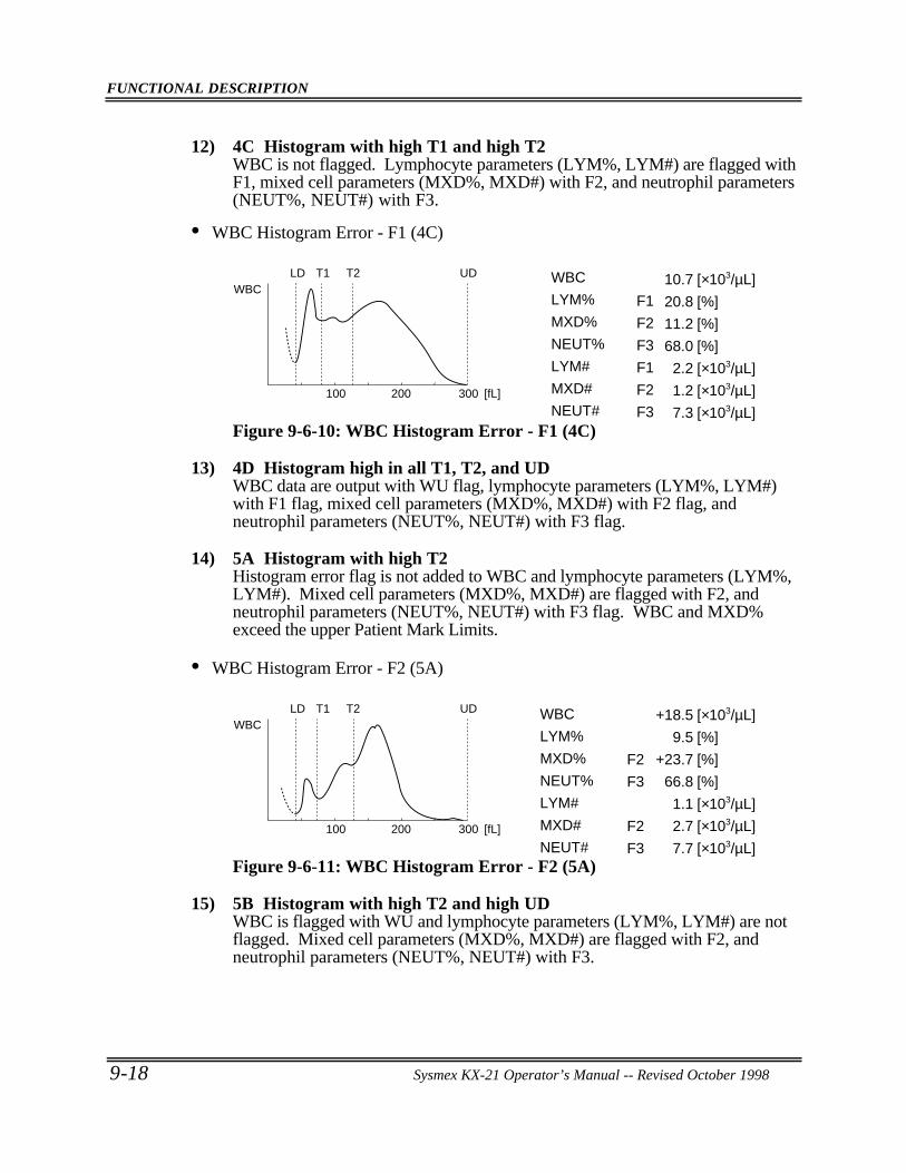
FUNCTIONAL DESCRIPTION
9-18 Sysmex KX-21 Operator’s Manual -- Revised October 1998
12) 4C Histogram with high T1 and high T2WBC is not flagged. Lymphocyte parameters (LYM%, LYM#) are flagged withF1, mixed cell parameters (MXD%, MXD#) with F2, and neutrophil parameters(NEUT%, NEUT#) with F3.
• WBC Histogram Error - F1 (4C)
WBCUDLD T1 T2 10.7
20.8
11.2
68.0
2.2
1.2
7.3
[×103/µL]
[%]
[%]
[%]
[×103/µL]
[×103/µL]
[×103/µL]300200100 [fL]
F1
F2
F3
F1
F2
F3
WBC
LYM%
MXD%
NEUT%
LYM#
MXD#
NEUT#Figure 9-6-10: WBC Histogram Error - F1 (4C)
13) 4D Histogram high in all T1, T2, and UDWBC data are output with WU flag, lymphocyte parameters (LYM%, LYM#)with F1 flag, mixed cell parameters (MXD%, MXD#) with F2 flag, andneutrophil parameters (NEUT%, NEUT#) with F3 flag.
14) 5A Histogram with high T2Histogram error flag is not added to WBC and lymphocyte parameters (LYM%,LYM#). Mixed cell parameters (MXD%, MXD#) are flagged with F2, andneutrophil parameters (NEUT%, NEUT#) with F3 flag. WBC and MXD%exceed the upper Patient Mark Limits.
• WBC Histogram Error - F2 (5A)
WBCUDLD T1 T2 +18.5
9.5
+23.7
66.8
1.1
2.7
7.7
[×103/µL]
[%]
[%]
[%]
[×103/µL]
[×103/µL]
[×103/µL]300200100 [fL]
F2
F3
F2
F3
WBC
LYM%
MXD%
NEUT%
LYM#
MXD#
NEUT#Figure 9-6-11: WBC Histogram Error - F2 (5A)
15) 5B Histogram with high T2 and high UDWBC is flagged with WU and lymphocyte parameters (LYM%, LYM#) are notflagged. Mixed cell parameters (MXD%, MXD#) are flagged with F2, andneutrophil parameters (NEUT%, NEUT#) with F3.
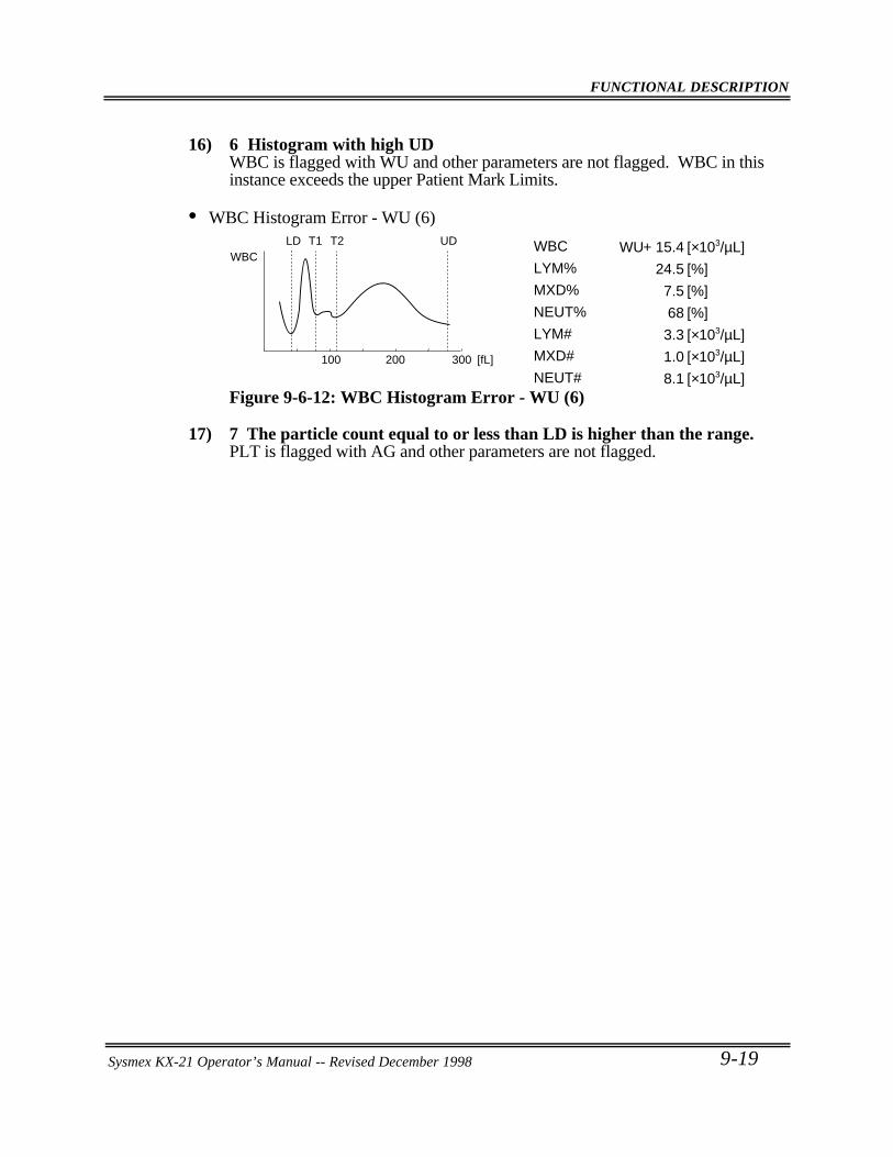
FUNCTIONAL DESCRIPTION
Sysmex KX-21 Operator’s Manual -- Revised October 1998 9-19
16) 6 Histogram with high UDWBC is flagged with WU and other parameters are not flagged. WBC in thisinstance exceeds the upper Patient Mark Limits.
• WBC Histogram Error - WU (6)
WBCUDLD T1 T2 + 15.4
24.5
7.5
68
3.3
1.0
8.1
[×103/µL]
[%]
[%]
[%]
[×103/µL]
[×103/µL]
[×103/µL]300200100 [fL]
WUWBC
LYM%
MXD%
NEUT%
LYM#
MXD#
NEUT#Figure 9-6-12: WBC Histogram Error - WU (6)
17) 7 The particle count equal to or less than LD is higher than the range.PLT is flagged with AG and other parameters are not flagged.
Sysmex KX-21 Operator’s Manual -- Revised December 1998
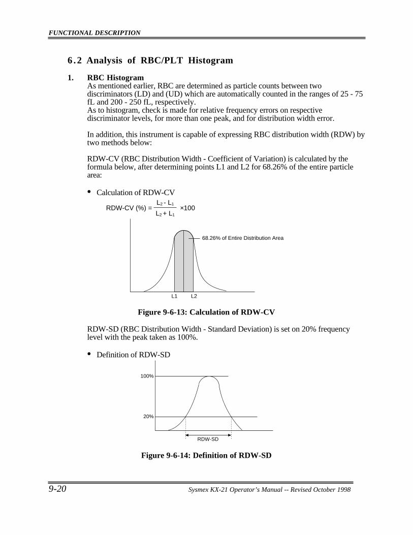
FUNCTIONAL DESCRIPTION
9-20 Sysmex KX-21 Operator’s Manual -- Revised October 1998
6 .2 Analysis of RBC/PLT Histogram
1. RBC HistogramAs mentioned earlier, RBC are determined as particle counts between twodiscriminators (LD) and (UD) which are automatically counted in the ranges of 25 - 75fL and 200 - 250 fL, respectively.As to histogram, check is made for relative frequency errors on respectivediscriminator levels, for more than one peak, and for distribution width error.
In addition, this instrument is capable of expressing RBC distribution width (RDW) bytwo methods below:
RDW-CV (RBC Distribution Width - Coefficient of Variation) is calculated by theformula below, after determining points L1 and L2 for 68.26% of the entire particlearea:
• Calculation of RDW-CV
RDW-CV (%) =L2 - L1
L2 + L1
×100
L2L1
68.26% of Entire Distribution Area
Figure 9-6-13: Calculation of RDW-CV
RDW-SD (RBC Distribution Width - Standard Deviation) is set on 20% frequencylevel with the peak taken as 100%.
• Definition of RDW-SD
100%
20%
RDW-SD
Figure 9-6-14: Definition of RDW-SD
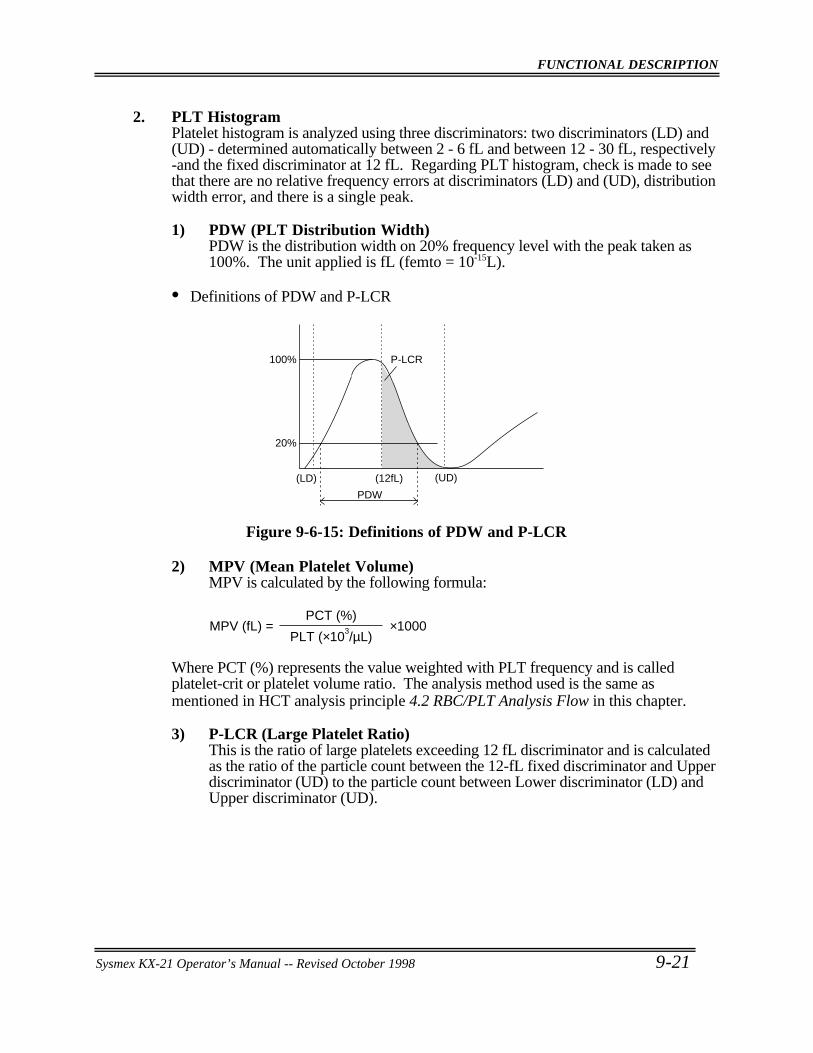
FUNCTIONAL DESCRIPTION
Sysmex KX-21 Operator’s Manual -- Revised October 1998 9-21
2. PLT HistogramPlatelet histogram is analyzed using three discriminators: two discriminators (LD) and(UD) - determined automatically between 2 - 6 fL and between 12 - 30 fL, respectively-and the fixed discriminator at 12 fL. Regarding PLT histogram, check is made to seethat there are no relative frequency errors at discriminators (LD) and (UD), distributionwidth error, and there is a single peak.
1) PDW (PLT Distribution Width)PDW is the distribution width on 20% frequency level with the peak taken as100%. The unit applied is fL (femto = 10-15L).
• Definitions of PDW and P-LCR
100%
20%
P-LCR
(LD) (UD)(12fL)
PDW
Figure 9-6-15: Definitions of PDW and P-LCR
2) MPV (Mean Platelet Volume)MPV is calculated by the following formula:
MPV (fL) =PCT (%)
PLT (×103/µL)×1000
Where PCT (%) represents the value weighted with PLT frequency and is calledplatelet-crit or platelet volume ratio. The analysis method used is the same asmentioned in HCT analysis principle 4.2 RBC/PLT Analysis Flow in this chapter.
3) P-LCR (Large Platelet Ratio)This is the ratio of large platelets exceeding 12 fL discriminator and is calculatedas the ratio of the particle count between the 12-fL fixed discriminator and Upperdiscriminator (UD) to the particle count between Lower discriminator (LD) andUpper discriminator (UD).
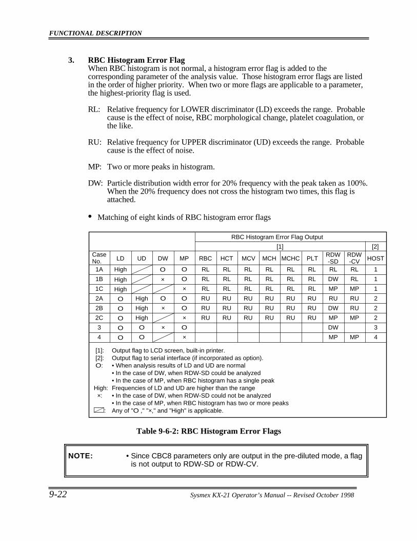
FUNCTIONAL DESCRIPTION
9-22 Sysmex KX-21 Operator’s Manual -- Revised October 1998
3. RBC Histogram Error FlagWhen RBC histogram is not normal, a histogram error flag is added to thecorresponding parameter of the analysis value. Those histogram error flags are listedin the order of higher priority. When two or more flags are applicable to a parameter,the highest-priority flag is used.
RL: Relative frequency for LOWER discriminator (LD) exceeds the range. Probablecause is the effect of noise, RBC morphological change, platelet coagulation, orthe like.
RU: Relative frequency for UPPER discriminator (UD) exceeds the range. Probablecause is the effect of noise.
MP: Two or more peaks in histogram.
DW: Particle distribution width error for 20% frequency with the peak taken as 100%.When the 20% frequency does not cross the histogram two times, this flag isattached.
• Matching of eight kinds of RBC histogram error flags
RBC Histogram Error Flag Output
[1] [2]
[1]: Output flag to LCD screen, built-in printer. [2]: Output flag to serial interface (if incorporated as option). O: • When analysis results of LD and UD are normal • In the case of DW, when RDW-SD could be analyzed • In the case of MP, when RBC histogram has a single peak High: Frequencies of LD and UD are higher than the range ×: • In the case of DW, when RDW-SD could not be analyzed • In the case of MP, when RBC histogram has two or more peaks : Any of "O ," "×," and "High" is applicable.
Case No. LD UD DW MP RBC HCT MCV MCH MCHC PLT
RDW-SD HOST
1A
1B
1C
2A
2B
2C
3
4
High
High
High
O
O
O
O
O
High
High
High
O
O
O
×
×
O
O
×O
O
×O
×
RL
RL
RL
RU
RU
RU
RL
RL
RL
RU
RU
RU
RL
RL
RL
RU
RU
RU
RL
RL
RL
RU
RU
RU
RL
RL
RL
RU
RU
RU
RL
RL
RL
RU
RU
RU
RL
DW
MP
RU
DW
MP
DW
MP
RDW-CVRL
RL
MP
RU
RU
MP
MP
1
1
1
2
2
2
3
4
O
×
Table 9-6-2: RBC Histogram Error Flags
NOTE: • Since CBC8 parameters only are output in the pre-diluted mode, a flagis not output to RDW-SD or RDW-CV.
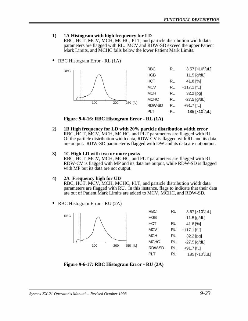
FUNCTIONAL DESCRIPTION
Sysmex KX-21 Operator’s Manual -- Revised October 1998 9-23
1) 1A Histogram with high frequency for LDRBC, HCT, MCV, MCH, MCHC, PLT, and particle distribution width dataparameters are flagged with RL. MCV and RDW-SD exceed the upper PatientMark Limits, and MCHC falls below the lower Patient Mark Limits.
• RBC Histogram Error - RL (1A)
3.57
11.5
41.8
+117.1
32.2
-27.5
+91.7
185
[×106/µL]
[g/dL]
[%]
[fL]
[pg]
[g/dL]
[fL]
[×103/µL]
RBC
250200100 [fL]
RBC
HGB
HCT
MCV
MCH
MCHC
RDW-SD
PLT
RL
RL
RL
RL
RL
RL
RL
Figure 9-6-16: RBC Histogram Error - RL (1A)
2) 1B High frequency for LD with 20% particle distribution width errorRBC, HCT, MCV, MCH, MCHC, and PLT parameters are flagged with RL.Of the particle distribution width data, RDW-CV is flagged with RL and its dataare output. RDW-SD parameter is flagged with DW and its data are not output.
3) 1C High LD with two or more peaksRBC, HCT, MCV, MCH, MCHC, and PLT parameters are flagged with RL.RDW-CV is flagged with MP and its data are output, while RDW-SD is flaggedwith MP but its data are not output.
4) 2A Frequency high for UDRBC, HCT, MCV, MCH, MCHC, PLT, and particle distribution width dataparameters are flagged with RU. In this instance, flags to indicate that their dataare out of Patient Mark Limits are added to MCV, MCHC, and RDW-SD.
• RBC Histogram Error - RU (2A)
3.57
11.5
41.8
+117.1
32.2
-27.5
+91.7
185
RBC [×106/µL]
[g/dL]
[%]
[fL]
[pg]
[g/dL]
[fL]
[×103/µL]
250200100 [fL]
RBC
HGB
HCT
MCV
MCH
MCHC
RDW-SD
PLT
RU
RU
RU
RU
RU
RU
RU
Figure 9-6-17: RBC Histogram Error - RU (2A)
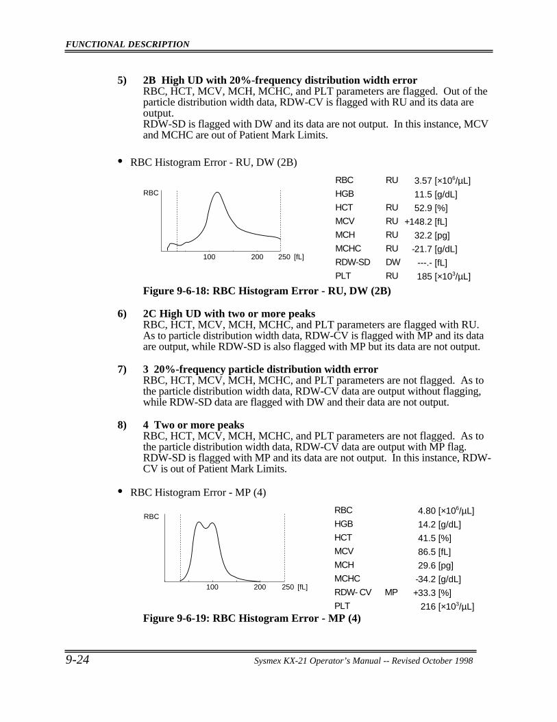
FUNCTIONAL DESCRIPTION
9-24 Sysmex KX-21 Operator’s Manual -- Revised October 1998
5) 2B High UD with 20%-frequency distribution width errorRBC, HCT, MCV, MCH, MCHC, and PLT parameters are flagged. Out of theparticle distribution width data, RDW-CV is flagged with RU and its data areoutput.RDW-SD is flagged with DW and its data are not output. In this instance, MCVand MCHC are out of Patient Mark Limits.
• RBC Histogram Error - RU, DW (2B)
3.57
11.5
52.9
+148.2
32.2
-21.7
---.-
185
RBC
[×106/µL]
[g/dL]
[%]
[fL]
[pg]
[g/dL]
[fL]
[×103/µL]
250200100 [fL]
RBC
HGB
HCT
MCV
MCH
MCHC
RDW-SD
PLT
RU
RU
RU
RU
RU
DW
RU
Figure 9-6-18: RBC Histogram Error - RU, DW (2B)
6) 2C High UD with two or more peaksRBC, HCT, MCV, MCH, MCHC, and PLT parameters are flagged with RU.As to particle distribution width data, RDW-CV is flagged with MP and its dataare output, while RDW-SD is also flagged with MP but its data are not output.
7) 3 20%-frequency particle distribution width errorRBC, HCT, MCV, MCH, MCHC, and PLT parameters are not flagged. As tothe particle distribution width data, RDW-CV data are output without flagging,while RDW-SD data are flagged with DW and their data are not output.
8) 4 Two or more peaksRBC, HCT, MCV, MCH, MCHC, and PLT parameters are not flagged. As tothe particle distribution width data, RDW-CV data are output with MP flag.RDW-SD is flagged with MP and its data are not output. In this instance, RDW-CV is out of Patient Mark Limits.
• RBC Histogram Error - MP (4)
4.80
14.2
41.5
86.5
29.6
-34.2
+33.3
216
RBC [×106/µL]
[g/dL]
[%]
[fL]
[pg]
[g/dL]
[%]
[×103/µL]
250200100 [fL]
RBC
HGB
HCT
MCV
MCH
MCHC
RDW- CV
PLT
MP
Figure 9-6-19: RBC Histogram Error - MP (4)
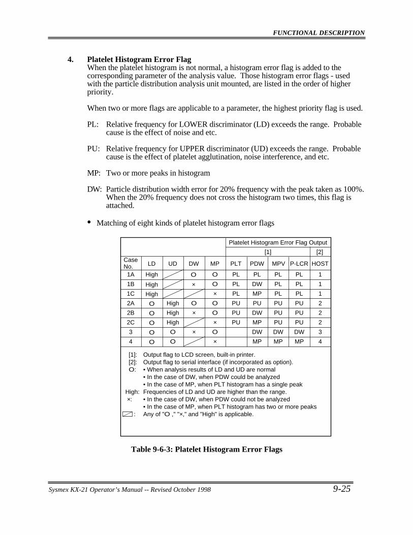
FUNCTIONAL DESCRIPTION
Sysmex KX-21 Operator’s Manual -- Revised October 1998 9-25
4. Platelet Histogram Error FlagWhen the platelet histogram is not normal, a histogram error flag is added to thecorresponding parameter of the analysis value. Those histogram error flags - usedwith the particle distribution analysis unit mounted, are listed in the order of higherpriority.
When two or more flags are applicable to a parameter, the highest priority flag is used.
PL: Relative frequency for LOWER discriminator (LD) exceeds the range. Probablecause is the effect of noise and etc.
PU: Relative frequency for UPPER discriminator (UD) exceeds the range. Probablecause is the effect of platelet agglutination, noise interference, and etc.
MP: Two or more peaks in histogram
DW: Particle distribution width error for 20% frequency with the peak taken as 100%.When the 20% frequency does not cross the histogram two times, this flag isattached.
• Matching of eight kinds of platelet histogram error flags
Platelet Histogram Error Flag Output
[1] [2]
[1]: Output flag to LCD screen, built-in printer. [2]: Output flag to serial interface (if incorporated as option). O: • When analysis results of LD and UD are normal • In the case of DW, when PDW could be analyzed • In the case of MP, when PLT histogram has a single peak High: Frequencies of LD and UD are higher than the range. ×: • In the case of DW, when PDW could not be analyzed • In the case of MP, when PLT histogram has two or more peaks : Any of "O ," "×," and "High" is applicable.
Case No. LD UD DW MP PLT PDW MPV P-LCR HOST
1A
1B
1C
2A
2B
2C
3
4
High
High
High
O
O
O
O
O
High
High
High
O
O
O
×
×
O
O
×O
O
×O
×
PL
PL
PL
PU
PU
PU
PL
DW
MP
PU
DW
MP
DW
MP
PL
PL
PL
PU
PU
PU
DW
MP
PL
PL
PL
PU
PU
PU
DW
MP
1
1
1
2
2
2
3
4
O
×
Table 9-6-3: Platelet Histogram Error Flags
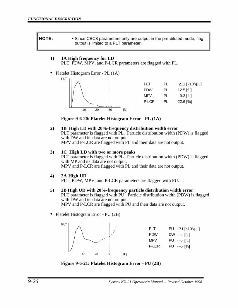
FUNCTIONAL DESCRIPTION
9-26 Sysmex KX-21 Operator’s Manual -- Revised October 1998
NOTE: • Since CBC8 parameters only are output in the pre-diluted mode, flagoutput is limited to a PLT parameter.
1) 1A High frequency for LDPLT, PDW, MPV, and P-LCR parameters are flagged with PL.
• Platelet Histogram Error - PL (1A)
211
12.5
9.3
-22.6
PLT
[×103/µL]
[fL]
[fL]
[%]
302010 [fL]
PLT
PDW
MPV
P-LCR
PL
PL
PL
PL
Figure 9-6-20: Platelet Histogram Error - PL (1A)
2) 1B High LD with 20%-frequency distribution width errorPLT parameter is flagged with PL. Particle distribution width (PDW) is flaggedwith DW and its data are not output.MPV and P-LCR are flagged with PL and their data are not output.
3) 1C High LD with two or more peaksPLT parameter is flagged with PL. Particle distribution width (PDW) is flaggedwith MP and its data are not output.MPV and P-LCR are flagged with PL and their data are not output.
4) 2A High UDPLT, PDW, MPV, and P-LCR parameters are flagged with PU.
5) 2B High UD with 20%-frequency particle distribution width errorPLT parameter is flagged with PU. Particle distribution width (PDW) is flaggedwith DW and its data are not output.MPV and P-LCR are flagged with PU and their data are not output.
• Platelet Histogram Error - PU (2B)
171
---.-
---.-
---.-
PLT
[×103/µL]
[fL]
[fL]
[%]
302010 [fL]
PLT
PDW
MPV
P-LCR
PU
DW
PU
PU
Figure 9-6-21: Platelet Histogram Error - PU (2B)
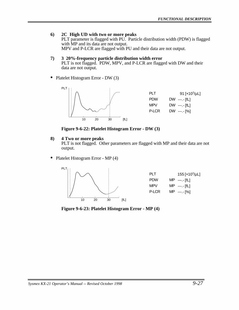
FUNCTIONAL DESCRIPTION
Sysmex KX-21 Operator’s Manual -- Revised October 1998 9-27
6) 2C High UD with two or more peaksPLT parameter is flagged with PU. Particle distribution width (PDW) is flaggedwith MP and its data are not output.MPV and P-LCR are flagged with PU and their data are not output.
7) 3 20%-frequency particle distribution width errorPLT is not flagged. PDW, MPV, and P-LCR are flagged with DW and theirdata are not output.
• Platelet Histogram Error - DW (3)
91
---.-
---.-
---.-
PLT
[×103/µL]
[fL]
[fL]
[%]
302010 [fL]
PLT
PDW
MPV
P-LCR
DW
DW
DW
Figure 9-6-22: Platelet Histogram Error - DW (3)
8) 4 Two or more peaksPLT is not flagged. Other parameters are flagged with MP and their data are notoutput.
• Platelet Histogram Error - MP (4)
155
---.-
---.-
---.-
PLT
[×103/µL]
[fL]
[fL]
[%]
302010 [fL]
PLT
PDW
MPV
P-LCR
MP
MP
MP
Figure 9-6-23: Platelet Histogram Error - MP (4)
FUNCTIONAL DESCRIPTION
9-28 Sysmex KX-21 Operator’s Manual -- Revised October 1998
7 . ELECTRIC SYSTEM
The microprocessor in the main unit controls the hydraulic system's solenoid valves andmaster valves, thus regulating the flow of samples, reagents, and waste in the hydraulicsystem.Electric signals received from various transducers go through the analogue circuit forelectrical waveform-processing, and to the microcomputer. The microcomputer converts theanalogue signals into digital signals for the calculation.
The WBC, RBC, and PLT cell signals are sent to the respective waveform-processingcircuits in the analogue circuit, where the noise in signals is eliminated to acquire the requiredcell signals only. The microcomputer converts the A/D-converted cell signals into particledistribution data, and outputs them to the built-in printer or to the host computer (optional).
To calculate HGB, absorbance of only the diluent (background) is deducted from samples'absorbance. The beam that has passed through the fluid is detected by the photo diode. Andthe signals is photoelectrically converted, A/D converted, and then sent to the HGB countingcircuit for the calculation of the absorbance.
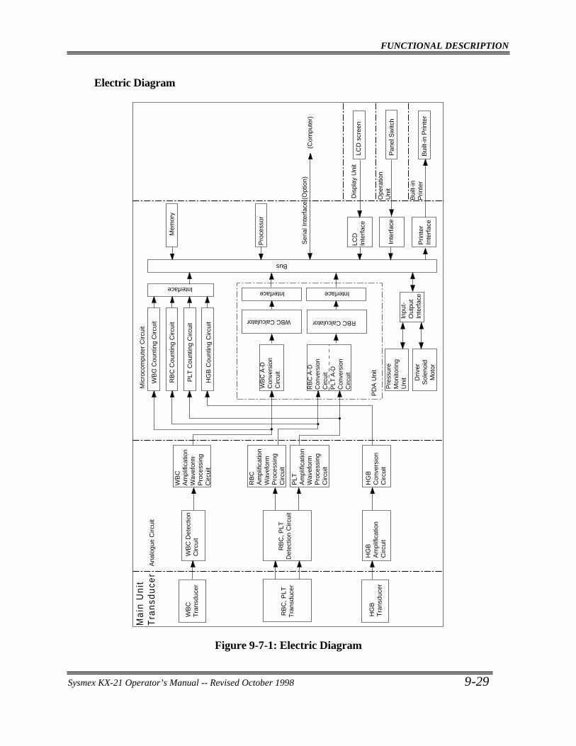
FUNCTIONAL DESCRIPTION
Sysmex KX-21 Operator’s Manual -- Revised October 1998 9-29
Electric Diagram
WB
C
Tra
nsdu
cer
WB
C D
etec
tion
Circ
uit
WB
C
Am
plifi
catio
nW
avef
orm
P
roce
ssin
g C
ircui
t
RB
C, P
LT
Tra
nsdu
cer
RB
C, P
LT
Det
ectio
n C
ircui
t
HG
BT
rans
duce
r
HG
B
Am
plifi
catio
n C
ircui
t
WB
C C
ount
ing
Circ
uit
RB
C C
ount
ing
Circ
uit
PLT
Cou
ntin
g C
ircui
t
HG
B C
ount
ing
Circ
uit
WB
C A
-D
Con
vers
ion
Circ
uit
RB
C A
-D
Con
vers
ion
Circ
uit
PLT
A-D
C
onve
rsio
n C
ircui
t
Pre
ssur
e M
onito
ring
Uni
t Driv
er
Sol
enoi
d M
otor
Inpu
t-O
utpu
t In
terf
ace
RB
C
Am
plifi
catio
n W
avef
orm
P
roce
ssin
g C
ircui
t
PLT
A
mpl
ifica
tion
Wav
efor
m
Pro
cess
ing
Circ
uit
HG
B
Con
vers
ion
Circ
uit
Mic
roco
mpu
ter
Circ
uit
WBC Calculator RBC Calculator
Ana
logu
e C
ircui
t
LCD
In
terf
ace
Inte
rfac
e
Prin
ter
Inte
rfac
e
LCD
scr
een
Pan
el S
witc
h
Bui
lt-in
Prin
ter
Ma
in U
nit
Tra
nsd
uce
r
PD
A U
nit
Ser
ial I
nter
face
(O
ptio
n)
Mem
ory
Pro
cess
or
(Com
pute
r)
Dis
play
Uni
t
Ope
ratio
n U
nit
Bui
lt-in
P
rinte
r
InterfaceInterface Interface
Bus
Figure 9-7-1: Electric Diagram
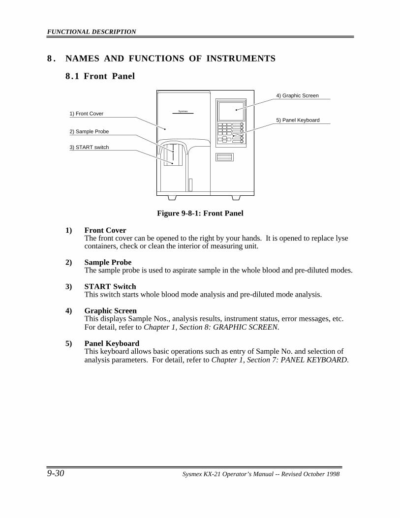
FUNCTIONAL DESCRIPTION
9-30 Sysmex KX-21 Operator’s Manual -- Revised October 1998
8 . NAMES AND FUNCTIONS OF INSTRUMENTS
8 .1 Front Panel
Sysmex
4) Graphic Screen
5) Panel Keyboard1) Front Cover
2) Sample Probe
3) START switch
Figure 9-8-1: Front Panel
1) Front CoverThe front cover can be opened to the right by your hands. It is opened to replace lysecontainers, check or clean the interior of measuring unit.
2) Sample ProbeThe sample probe is used to aspirate sample in the whole blood and pre-diluted modes.
3) START SwitchThis switch starts whole blood mode analysis and pre-diluted mode analysis.
4) Graphic ScreenThis displays Sample Nos., analysis results, instrument status, error messages, etc.For detail, refer to Chapter 1, Section 8: GRAPHIC SCREEN.
5) Panel KeyboardThis keyboard allows basic operations such as entry of Sample No. and selection ofanalysis parameters. For detail, refer to Chapter 1, Section 7: PANEL KEYBOARD.
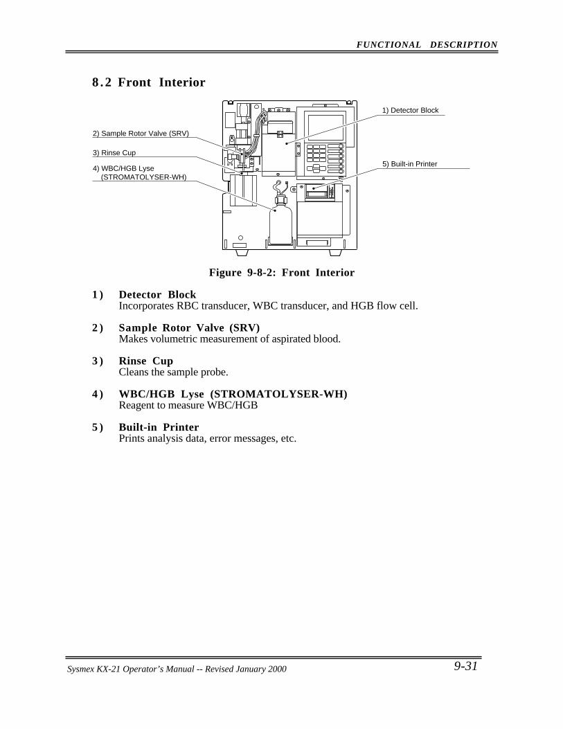
FUNCTIONAL DESCRIPTION
Sysmex KX-21 Operator’s Manual -- Revised October 1998 9-31
8 .2 Front Interior
1) Detector Block
5) Built-in Printer
2) Sample Rotor Valve (SRV)
3) Rinse Cup
4) WBC/HGB Lyse (STROMATOLYSER-WH)
Figure 9-8-2: Front Interior
1 ) Detector BlockIncorporates RBC transducer, WBC transducer, and HGB flow cell.
2 ) Sample Rotor Valve (SRV)Makes volumetric measurement of aspirated blood.
3 ) Rinse CupCleans the sample probe.
4 ) WBC/HGB Lyse (STROMATOLYSER-WH)Reagent to measure WBC/HGB
5 ) Built-in PrinterPrints analysis data, error messages, etc.
Sysmex KX-21 Operator’s Manual -- Revised January 2000
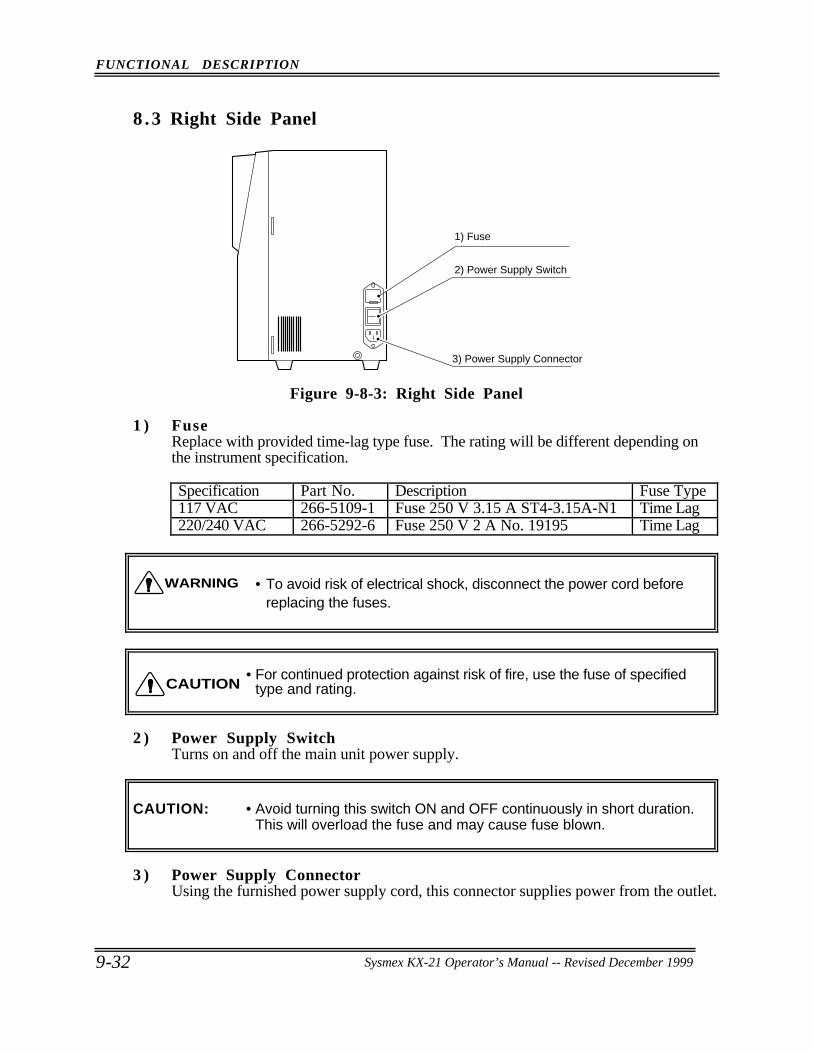
FUNCTIONAL DESCRIPTION
9-32 Sysmex KX-21 Operator’s Manual -- Revised October 1998
8 .3 Right Side Panel
2) Power Supply Switch
1) Fuse
3) Power Supply Connector
Figure 9-8-3: Right Side Panel
1 ) FuseReplace with provided time-lag type fuse. The rating will be different depending onthe instrument specification.
Specification Part No. Description Fuse Type117 VAC 266-5109-1 Fuse 250 V 3.15 A ST4-3.15A-N1 Time Lag220/240 VAC 266-5292-6 Fuse 250 V 2 A No. 19195 Time Lag
• To avoid risk of electrical shock, disconnect the power cord beforereplacing the fuses.
• For continued protection against risk of fire, use the fuse of specifiedtype and rating.
2 ) Power Supply SwitchTurns on and off the main unit power supply.
CAUTION: • Avoid turning this switch ON and OFF continuously in short duration.This will overload the fuse and may cause fuse blown.
3 ) Power Supply ConnectorUsing the furnished power supply cord, this connector supplies power from the outlet.
WARNING
CAUTION
Sysmex KX-21 Operator’s Manual -- Revised December 1999
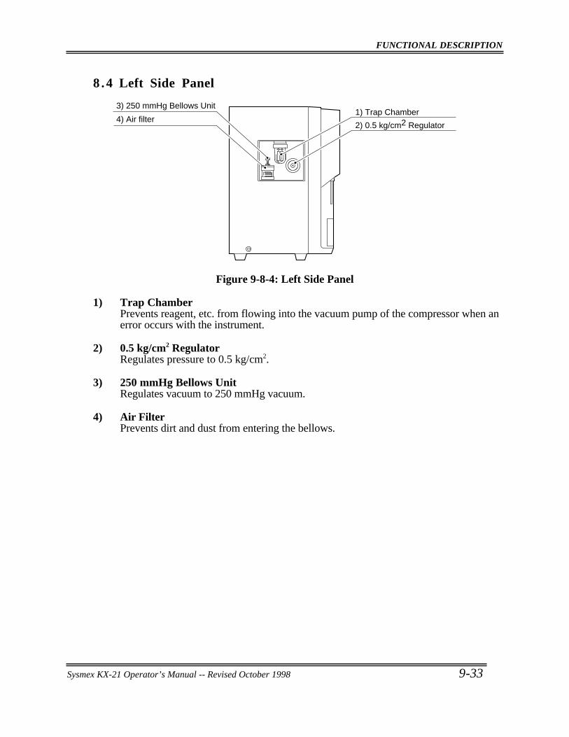
FUNCTIONAL DESCRIPTION
Sysmex KX-21 Operator’s Manual -- Revised October 1998 9-33
8 .4 Left Side Panel
3) 250 mmHg Bellows Unit
4) Air filter2) 0.5 kg/cm2 Regulator
1) Trap Chamber
Figure 9-8-4: Left Side Panel
1) Trap ChamberPrevents reagent, etc. from flowing into the vacuum pump of the compressor when anerror occurs with the instrument.
2) 0.5 kg/cm2 RegulatorRegulates pressure to 0.5 kg/cm2.
3) 250 mmHg Bellows UnitRegulates vacuum to 250 mmHg vacuum.
4) Air FilterPrevents dirt and dust from entering the bellows.
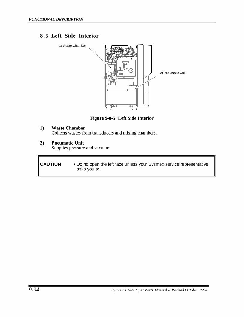
FUNCTIONAL DESCRIPTION
9-34 Sysmex KX-21 Operator’s Manual -- Revised October 1998
8 .5 Left Side Interior
1) Waste Chamber
2) Pneumatic Unit
Figure 9-8-5: Left Side Interior
1) Waste ChamberCollects wastes from transducers and mixing chambers.
2) Pneumatic UnitSupplies pressure and vacuum.
CAUTION: • Do no open the left face unless your Sysmex service representativeasks you to.
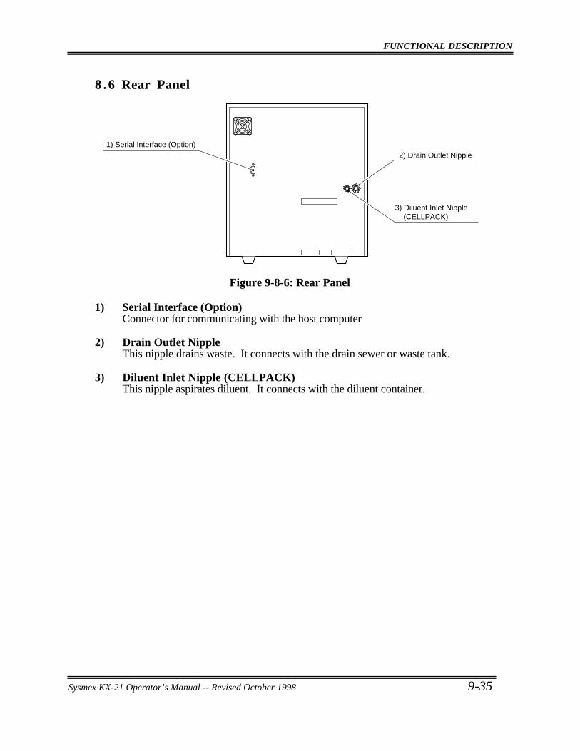
FUNCTIONAL DESCRIPTION
Sysmex KX-21 Operator’s Manual -- Revised October 1998 9-35
8 .6 Rear Panel
2) Drain Outlet Nipple
3) Diluent Inlet Nipple (CELLPACK)
1) Serial Interface (Option)
Figure 9-8-6: Rear Panel
1) Serial Interface (Option)Connector for communicating with the host computer
2) Drain Outlet NippleThis nipple drains waste. It connects with the drain sewer or waste tank.
3) Diluent Inlet Nipple (CELLPACK)This nipple aspirates diluent. It connects with the diluent container.
Sysmex KX-21 Operator’s Manual -- Revised January 2000
CHAPTER 10 INSTRUMENT SETUP
1. INTRODUCTION ... . . . . . . . . . . . . . . . . . . . . . . . . . . . . . . . . . . . . . . . . . . . . . . . . . . . . . . . . . . . . 10-1
2. SYSTEM SETUP... . . . . . . . . . . . . . . . . . . . . . . . . . . . . . . . . . . . . . . . . . . . . . . . . . . . . . . . . . . . . . 10-2
3. DATE/TIME SETTINGS ... . . . . . . . . . . . . . . . . . . . . . . . . . . . . . . . . . . . . . . . . . . . . . . . . . . . . 10-7
4. PATIENT LIMIT ... . . . . . . . . . . . . . . . . . . . . . . . . . . . . . . . . . . . . . . . . . . . . . . . . . . . . . . . . . . . . 10-10
5. QC SETTINGS ... . . . . . . . . . . . . . . . . . . . . . . . . . . . . . . . . . . . . . . . . . . . . . . . . . . . . . . . . . . . . . . 10-13
6. HOST SETTINGS (OPTION) ... . . . . . . . . . . . . . . . . . . . . . . . . . . . . . . . . . . . . . . . . . . . . . 10-16
7. PRINTER SETTINGS... . . . . . . . . . . . . . . . . . . . . . . . . . . . . . . . . . . . . . . . . . . . . . . . . . . . . . . 10-21
8. PRINT SET VALUES ... . . . . . . . . . . . . . . . . . . . . . . . . . . . . . . . . . . . . . . . . . . . . . . . . . . . . . . 10-24
9. PERIPHERAL SETTINGS ... . . . . . . . . . . . . . . . . . . . . . . . . . . . . . . . . . . . . . . . . . . . . . . . . 10-25
10. FACTORY SETTINGS... . . . . . . . . . . . . . . . . . . . . . . . . . . . . . . . . . . . . . . . . . . . . . . . . . . . . . 10-27
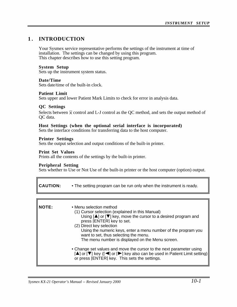
INSTRUMENT SETUP
Sysmex KX-21 Operator’s Manual -- Revised October 1998 10-1
1 . INTRODUCTION
Your Sysmex service representative performs the settings of the instrument at time ofinstallation. The settings can be changed by using this program.This chapter describes how to use this setting program.
System SetupSets up the instrument system status.
Date/TimeSets date/time of the built-in clock.
Patient LimitSets upper and lower Patient Mark Limits to check for error in analysis data.
QC SettingsSelects between X control and L-J control as the QC method, and sets the output method ofQC data.
Host Settings (when the optional serial interface is incorporated)Sets the interface conditions for transferring data to the host computer.
Printer SettingsSets the output selection and output conditions of the built-in printer.
Print Set ValuesPrints all the contents of the settings by the built-in printer.
Peripheral SettingSets whether to Use or Not Use of the built-in printer or the host computer (option) output.
CAUTION: • The setting program can be run only when the instrument is ready.
NOTE: • Menu selection method(1) Cursor selection (explained in this Manual)
Using [ ] or [ ] key, move the cursor to a desired program andpress [ENTER] key to set.
(2) Direct key selectionUsing the numeric keys, enter a menu number of the program youwant to set, thus selecting the menu.The menu number is displayed on the Menu screen.
• Change set values and move the cursor to the next parameter using[ ] or [ ] key ([ ] or [ ] key also can be used in Patient Limit setting)or press [ENTER] key. This sets the settings.
Sysmex KX-21 Operator’s Manual -- Revised January 2000
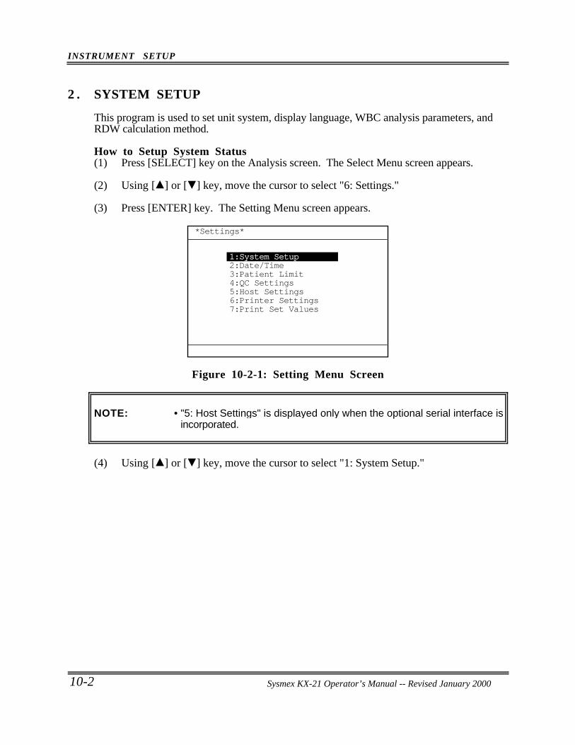
INSTRUMENT SETUP
10-2 Sysmex KX-21 Operator’s Manual -- Revised October 1998
2 . SYSTEM SETUP
This program is used to set unit system, display language, WBC analysis parameters, andRDW calculation method.
How to Setup System Status(1) Press [SELECT] key on the Analysis screen. The Select Menu screen appears.
(2) Using [ ] or [ ] key, move the cursor to select "6: Settings."
(3) Press [ENTER] key. The Setting Menu screen appears.
*Settings*
1:System Setup2:Date/Time3:Patient Limit4:QC Settings5:Host Settings6:Printer Settings7:Print Set Values
Figure 10-2-1: Setting Menu Screen
NOTE: • "5: Host Settings" is displayed only when the optional serial interface isincorporated.
(4) Using [ ] or [ ] key, move the cursor to select "1: System Setup."
Sysmex KX-21 Operator’s Manual -- Revised January 2000
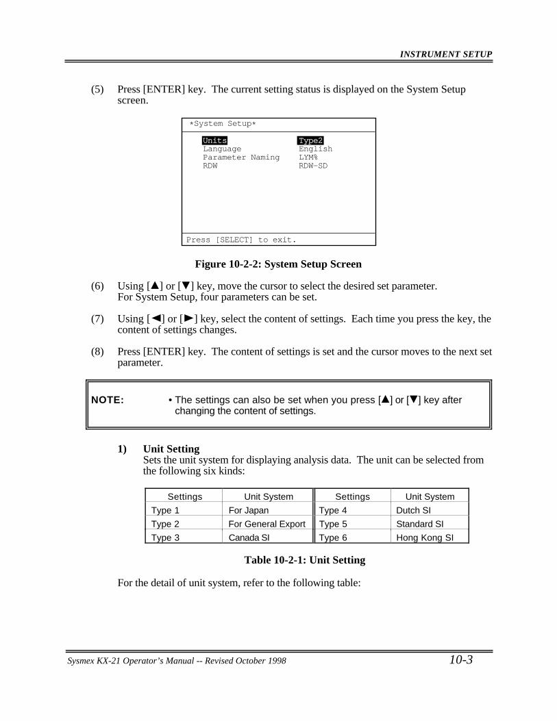
INSTRUMENT SETUP
Sysmex KX-21 Operator’s Manual -- Revised October 1998 10-3
(5) Press [ENTER] key. The current setting status is displayed on the System Setupscreen.
Units Type2
RDW RDW-SDParameter Naming LYM%Language English
*System Setup*
Press [SELECT] to exit.
Figure 10-2-2: System Setup Screen
(6) Using [ ] or [ ] key, move the cursor to select the desired set parameter.For System Setup, four parameters can be set.
(7) Using [ ] or [ ] key, select the content of settings. Each time you press the key, thecontent of settings changes.
(8) Press [ENTER] key. The content of settings is set and the cursor moves to the next setparameter.
NOTE: • The settings can also be set when you press [ ] or [ ] key afterchanging the content of settings.
1) Unit SettingSets the unit system for displaying analysis data. The unit can be selected fromthe following six kinds:
Settings Unit System Settings Unit System
Type 1 For Japan Type 4 Dutch SI
Type 2 For General Export Type 5 Standard SI
Type 3 Canada SI Type 6 Hong Kong SI
Table 10-2-1: Unit Setting
For the detail of unit system, refer to the following table:
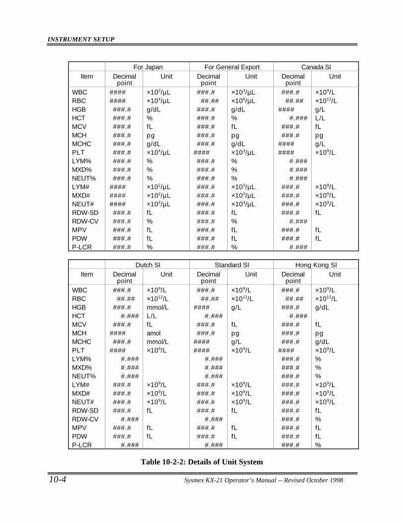
INSTRUMENT SETUP
10-4 Sysmex KX-21 Operator’s Manual -- Revised October 1998
For Japan For General Export Canada SIItem Decimal
pointUnit Decimal
pointUnit Decimal
pointUnit
WBCRBCHGBHCTMCVMCHMCHCPLTLYM%MXD%NEUT%LYM#MXD#NEUT#RDW-SDRDW-CVMPVPDWP-LCR
###########.####.####.####.####.####.####.####.####.#
###############.####.####.####.####.#
×102/µL×104/µLg/dL%fLpgg/dL×104/µL%%%×102/µL×102/µL×102/µLfL%fLfL%
###.###.##
###.####.####.####.####.#
#######.####.####.####.####.####.####.####.####.####.####.#
×103/µL×106/µLg/dL%fLpgg/dL×103/µL%%%×103/µL×103/µL×103/µLfL%fLfL%
###.###.##
#####.###
###.####.#
########
#.####.####.###
###.####.####.####.#
#.######.####.#
#.###
×109/L×1012/Lg/LL/LfLpgg/L×109/L
×109/L×109/L×109/LfL
fLfL
Dutch SI Standard SI Hong Kong SIItem Decimal
pointUnit Decimal
pointUnit Decimal
pointUnit
WBCRBCHGBHCTMCVMCHMCHCPLTLYM%MXD%NEUT%LYM#MXD#NEUT#RDW-SDRDW-CVMPVPDWP-LCR
###.###.##
###.##.###
###.########.#
#####.####.####.###
###.####.####.####.#
#.######.####.#
#.###
×109/L×1012/Lmmol/LL/LfLamolmmol/L×109/L
×109/L×109/L×109/LfL
fLfL
###.###.##
#####.###
###.####.#
########
#.####.####.###
###.####.####.####.#
#.######.####.#
#.###
×109/L×1012/Lg/L
fLpgg/L×109/L
×109/L×109/L×109/LfL
fLfL
###.###.##
###.##.###
###.####.####.#
#######.####.####.####.####.####.####.####.####.####.####.#
×109/L×1012/Lg/dL
fLpgg/dL×109/L%%%×109/L×109/L×109/LfL%fLfL%
Table 10-2-2: Details of Unit System
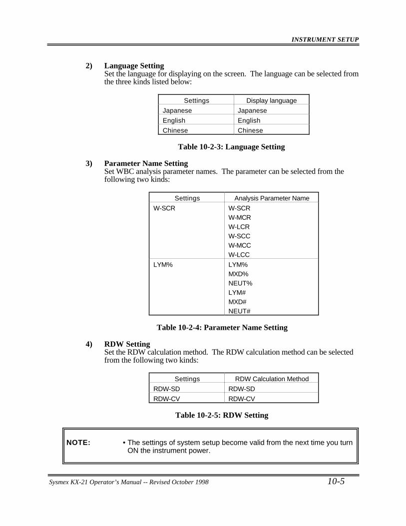
INSTRUMENT SETUP
Sysmex KX-21 Operator’s Manual -- Revised October 1998 10-5
2) Language SettingSet the language for displaying on the screen. The language can be selected fromthe three kinds listed below:
Settings Display language
Japanese Japanese
English English
Chinese Chinese
Table 10-2-3: Language Setting
3) Parameter Name SettingSet WBC analysis parameter names. The parameter can be selected from thefollowing two kinds:
Settings Analysis Parameter Name
W-SCR W-SCRW-MCRW-LCRW-SCCW-MCCW-LCC
LYM% LYM%MXD%NEUT%LYM#MXD#NEUT#
Table 10-2-4: Parameter Name Setting
4) RDW SettingSet the RDW calculation method. The RDW calculation method can be selectedfrom the following two kinds:
Settings RDW Calculation Method
RDW-SD RDW-SD
RDW-CV RDW-CV
Table 10-2-5: RDW Setting
NOTE: • The settings of system setup become valid from the next time you turnON the instrument power.
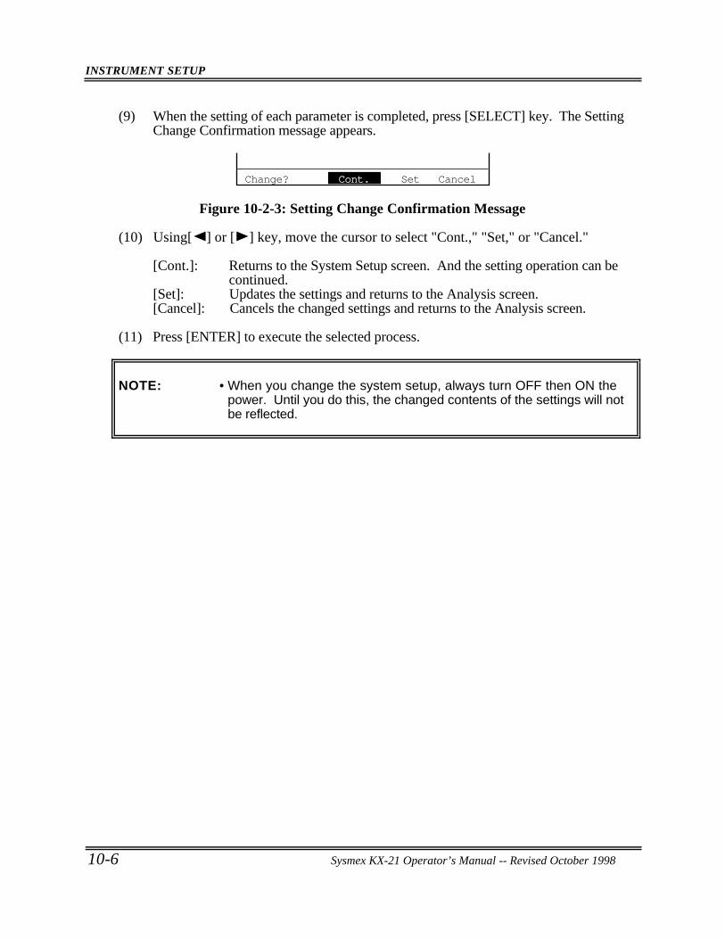
INSTRUMENT SETUP
10-6 Sysmex KX-21 Operator’s Manual -- Revised October 1998
(9) When the setting of each parameter is completed, press [SELECT] key. The SettingChange Confirmation message appears.
Change? Cont. Set Cancel
Figure 10-2-3: Setting Change Confirmation Message
(10) Using[ ] or [ ] key, move the cursor to select "Cont.," "Set," or "Cancel."
[Cont.]: Returns to the System Setup screen. And the setting operation can be continued.
[Set]: Updates the settings and returns to the Analysis screen.[Cancel]: Cancels the changed settings and returns to the Analysis screen.
(11) Press [ENTER] to execute the selected process.
NOTE: • When you change the system setup, always turn OFF then ON thepower. Until you do this, the changed contents of the settings will notbe reflected.
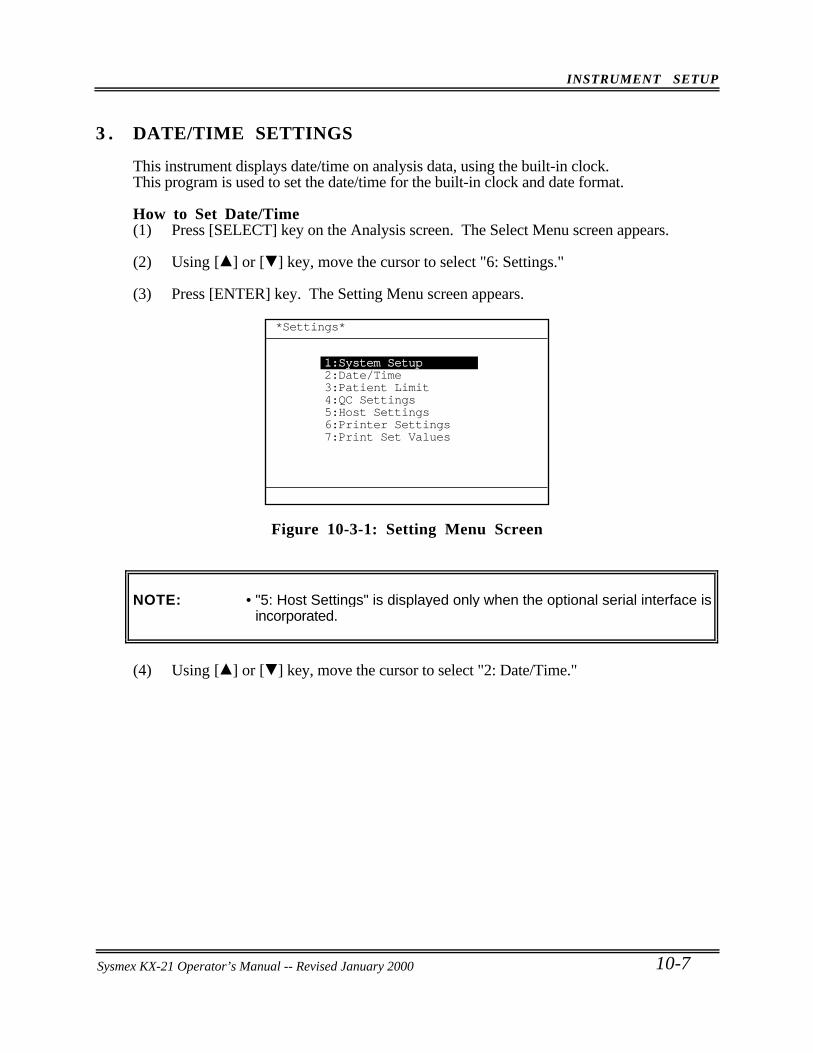
INSTRUMENT SETUP
Sysmex KX-21 Operator’s Manual -- Revised October 1998 10-7
3 . DATE/TIME SETTINGS
This instrument displays date/time on analysis data, using the built-in clock.This program is used to set the date/time for the built-in clock and date format.
How to Set Date/Time(1) Press [SELECT] key on the Analysis screen. The Select Menu screen appears.
(2) Using [ ] or [ ] key, move the cursor to select "6: Settings."
(3) Press [ENTER] key. The Setting Menu screen appears.
*Settings*
1:System Setup2:Date/Time3:Patient Limit4:QC Settings5:Host Settings6:Printer Settings7:Print Set Values
Figure 10-3-1: Setting Menu Screen
NOTE: • "5: Host Settings" is displayed only when the optional serial interface isincorporated.
(4) Using [ ] or [ ] key, move the cursor to select "2: Date/Time."
Sysmex KX-21 Operator’s Manual -- Revised January 2000
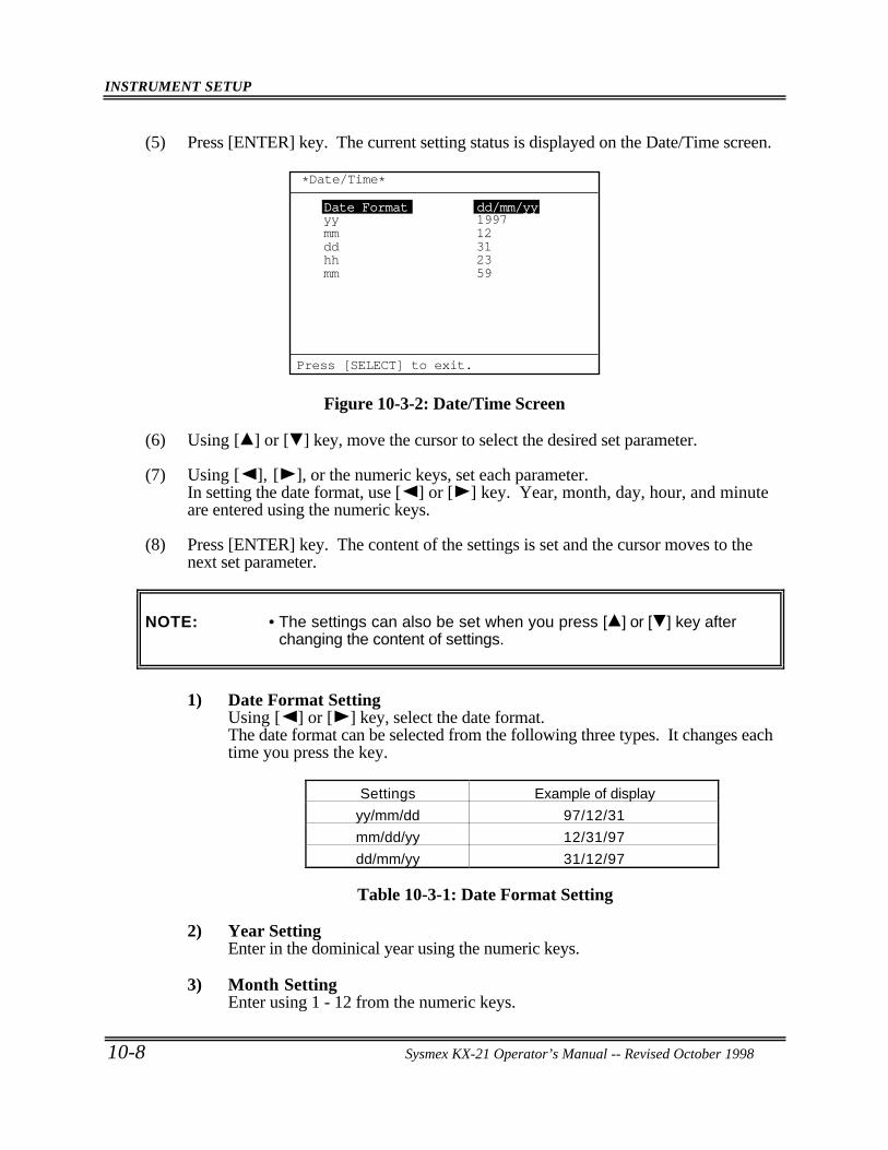
INSTRUMENT SETUP
10-8 Sysmex KX-21 Operator’s Manual -- Revised October 1998
(5) Press [ENTER] key. The current setting status is displayed on the Date/Time screen.
Date Format dd/mm/yy
dd 31mm 12yy 1997
mm 59hh 23
*Date/Time*
Press [SELECT] to exit.
Figure 10-3-2: Date/Time Screen
(6) Using [ ] or [ ] key, move the cursor to select the desired set parameter.
(7) Using [ ], [ ], or the numeric keys, set each parameter.In setting the date format, use [ ] or [ ] key. Year, month, day, hour, and minuteare entered using the numeric keys.
(8) Press [ENTER] key. The content of the settings is set and the cursor moves to thenext set parameter.
NOTE: • The settings can also be set when you press [ ] or [ ] key afterchanging the content of settings.
1) Date Format SettingUsing [ ] or [ ] key, select the date format.The date format can be selected from the following three types. It changes eachtime you press the key.
Settings Example of display
yy/mm/dd 97/12/31
mm/dd/yy 12/31/97
dd/mm/yy 31/12/97
Table 10-3-1: Date Format Setting
2) Year SettingEnter in the dominical year using the numeric keys.
3) Month SettingEnter using 1 - 12 from the numeric keys.
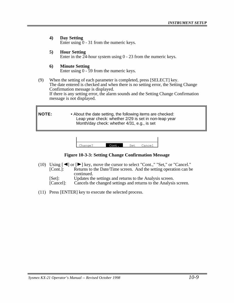
INSTRUMENT SETUP
Sysmex KX-21 Operator’s Manual -- Revised October 1998 10-9
4) Day SettingEnter using 0 - 31 from the numeric keys.
5) Hour SettingEnter in the 24-hour system using 0 - 23 from the numeric keys.
6) Minute SettingEnter using 0 - 59 from the numeric keys.
(9) When the setting of each parameter is completed, press [SELECT] key.The date entered is checked and when there is no setting error, the Setting ChangeConfirmation message is displayed.If there is any setting error, the alarm sounds and the Setting Change Confirmationmessage is not displayed.
NOTE: • About the date setting, the following items are checked:Leap year check: whether 2/29 is set in non-leap yearMonth/day check: whether 4/31, e.g., is set
Change? Cont. Set Cancel
Figure 10-3-3: Setting Change Confirmation Message
(10) Using [ ] or [ ] key, move the cursor to select "Cont.," "Set," or "Cancel."[Cont.]: Returns to the Date/Time screen. And the setting operation can be
continued.[Set]: Updates the settings and returns to the Analysis screen.[Cancel]: Cancels the changed settings and returns to the Analysis screen.
(11) Press [ENTER] key to execute the selected process.
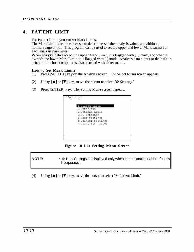
INSTRUMENT SETUP
10-10 Sysmex KX-21 Operator’s Manual -- Revised October 1998
4 . PATIENT LIMIT
For Patient Limit, you can set Mark Limits.The Mark Limits are the values set to determine whether analysis values are within thenormal range or not. This program can be used to set the upper and lower Mark Limits foreach analysis parameter.When analysis data exceeds the upper Mark Limit, it is flagged with [+] mark, and when itexceeds the lower Mark Limit, it is flagged with [-] mark. Analysis data output to the built-inprinter or the host computer is also attached with either marks.
How to Set Mark Limits(1) Press [SELECT] key on the Analysis screen. The Select Menu screen appears.
(2) Using [ ] or [ ] key, move the cursor to select "6: Settings."
(3) Press [ENTER] key. The Setting Menu screen appears.
*Settings*
1:System Setup2:Date/Time3:Patient Limit4:QC Settings5:Host Settings6:Printer Settings7:Print Set Values
Figure 10-4-1: Setting Menu Screen
NOTE: • "5: Host Settings" is displayed only when the optional serial interface isincorporated.
(4) Using [ ] or [ ] key, move the cursor to select "3: Patient Limit."
Sysmex KX-21 Operator’s Manual -- Revised January 2000
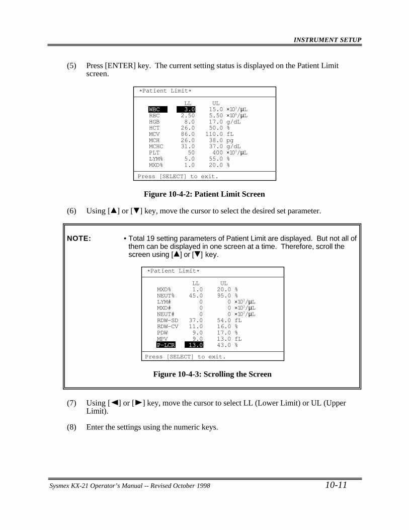
INSTRUMENT SETUP
Sysmex KX-21 Operator’s Manual -- Revised October 1998 10-11
(5) Press [ENTER] key. The current setting status is displayed on the Patient Limitscreen.
LL UL
HGB 8.0 17.0 g/dLRBC 2.50 5.50 ×10⁶/µLWBC 3.0 15.0 ×10³/µL
MCV 86.0 110.0 fLHCT 26.0 50.0 %
MCH 26.0 38.0 pg
PLT 50 400 ×103/µLMCHC 31.0 37.0 g/dL
LYM% 5.0 55.0 %MXD% 1.0 20.0 %
*Patient Limit*
Press [SELECT] to exit.
Figure 10-4-2: Patient Limit Screen
(6) Using [ ] or [ ] key, move the cursor to select the desired set parameter.
NOTE: • Total 19 setting parameters of Patient Limit are displayed. But not all ofthem can be displayed in one screen at a time. Therefore, scroll thescreen using [ ] or [ ] key.
LL UL
LYM# 0 0 ×103/µLNEUT% 45.0 95.0 %MXD% 1.0 20.0 %
NEUT# 0 0 ×103/µLMXD# 0 0 ×103/µL
RDW-SD 37.0 54.0 fL
PDW 9.0 17.0 %RDW-CV 11.0 16.0 %
MPV 9.0 13.0 fLP-LCR 13.0 43.0 %
*Patient Limit*
Press [SELECT] to exit.
Figure 10-4-3: Scrolling the Screen
(7) Using [ ] or [ ] key, move the cursor to select LL (Lower Limit) or UL (UpperLimit).
(8) Enter the settings using the numeric keys.
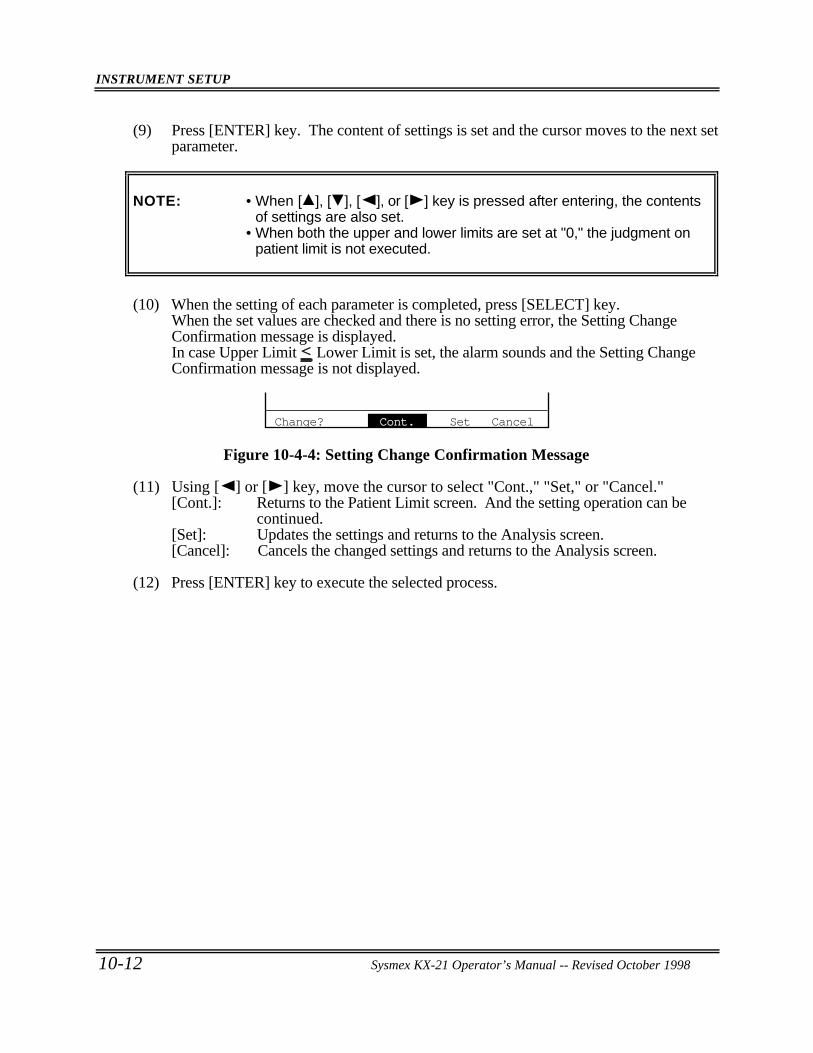
INSTRUMENT SETUP
10-12 Sysmex KX-21 Operator’s Manual -- Revised October 1998
(9) Press [ENTER] key. The content of settings is set and the cursor moves to the next setparameter.
NOTE: • When [ ], [ ], [ ], or [ ] key is pressed after entering, the contentsof settings are also set.
• When both the upper and lower limits are set at "0," the judgment onpatient limit is not executed.
(10) When the setting of each parameter is completed, press [SELECT] key.When the set values are checked and there is no setting error, the Setting ChangeConfirmation message is displayed.In case Upper Limit < Lower Limit is set, the alarm sounds and the Setting ChangeConfirmation message is not displayed.
Change? Cont. Set Cancel
Figure 10-4-4: Setting Change Confirmation Message
(11) Using [ ] or [ ] key, move the cursor to select "Cont.," "Set," or "Cancel."[Cont.]: Returns to the Patient Limit screen. And the setting operation can be
continued.[Set]: Updates the settings and returns to the Analysis screen.[Cancel]: Cancels the changed settings and returns to the Analysis screen.
(12) Press [ENTER] key to execute the selected process.
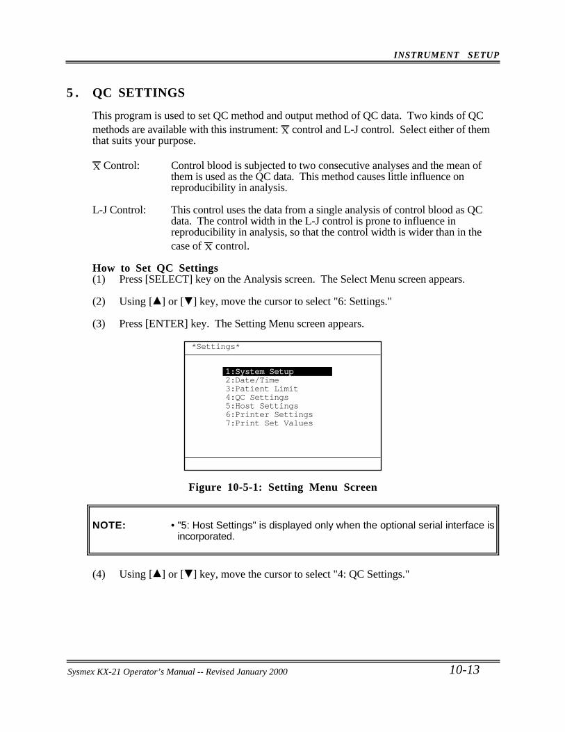
INSTRUMENT SETUP
Sysmex KX-21 Operator’s Manual -- Revised October 1998 10-13
5 . QC SETTINGS
This program is used to set QC method and output method of QC data. Two kinds of QCmethods are available with this instrument: X control and L-J control. Select either of themthat suits your purpose.
X Control: Control blood is subjected to two consecutive analyses and the mean of them is used as the QC data. This method causes little influence on reproducibility in analysis.
L-J Control: This control uses the data from a single analysis of control blood as QC data. The control width in the L-J control is prone to influence in reproducibility in analysis, so that the control width is wider than in the case of X control.
How to Set QC Settings(1) Press [SELECT] key on the Analysis screen. The Select Menu screen appears.
(2) Using [ ] or [ ] key, move the cursor to select "6: Settings."
(3) Press [ENTER] key. The Setting Menu screen appears.
*Settings*
1:System Setup2:Date/Time3:Patient Limit4:QC Settings5:Host Settings6:Printer Settings7:Print Set Values
Figure 10-5-1: Setting Menu Screen
NOTE: • "5: Host Settings" is displayed only when the optional serial interface isincorporated.
(4) Using [ ] or [ ] key, move the cursor to select "4: QC Settings."
Sysmex KX-21 Operator’s Manual -- Revised January 2000
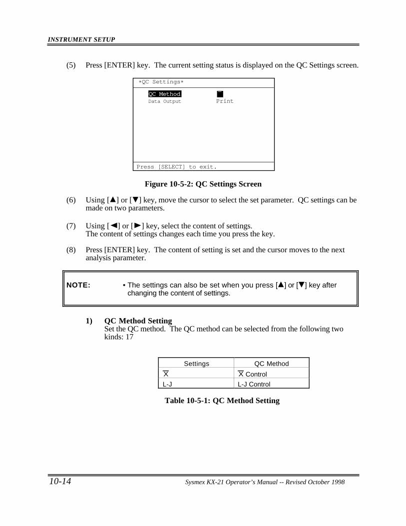
INSTRUMENT SETUP
10-14 Sysmex KX-21 Operator’s Manual -- Revised October 1998
(5) Press [ENTER] key. The current setting status is displayed on the QC Settings screen.
Data Output Print
*QC Settings*
Press [SELECT] to exit.
QC Method X
Figure 10-5-2: QC Settings Screen
(6) Using [ ] or [ ] key, move the cursor to select the set parameter. QC settings can bemade on two parameters.
(7) Using [ ] or [ ] key, select the content of settings.The content of settings changes each time you press the key.
(8) Press [ENTER] key. The content of setting is set and the cursor moves to the nextanalysis parameter.
NOTE: • The settings can also be set when you press [ ] or [ ] key afterchanging the content of settings.
1) QC Method SettingSet the QC method. The QC method can be selected from the following twokinds: 17
Settings QC Method
X X Control
L-J L-J Control
Table 10-5-1: QC Method Setting
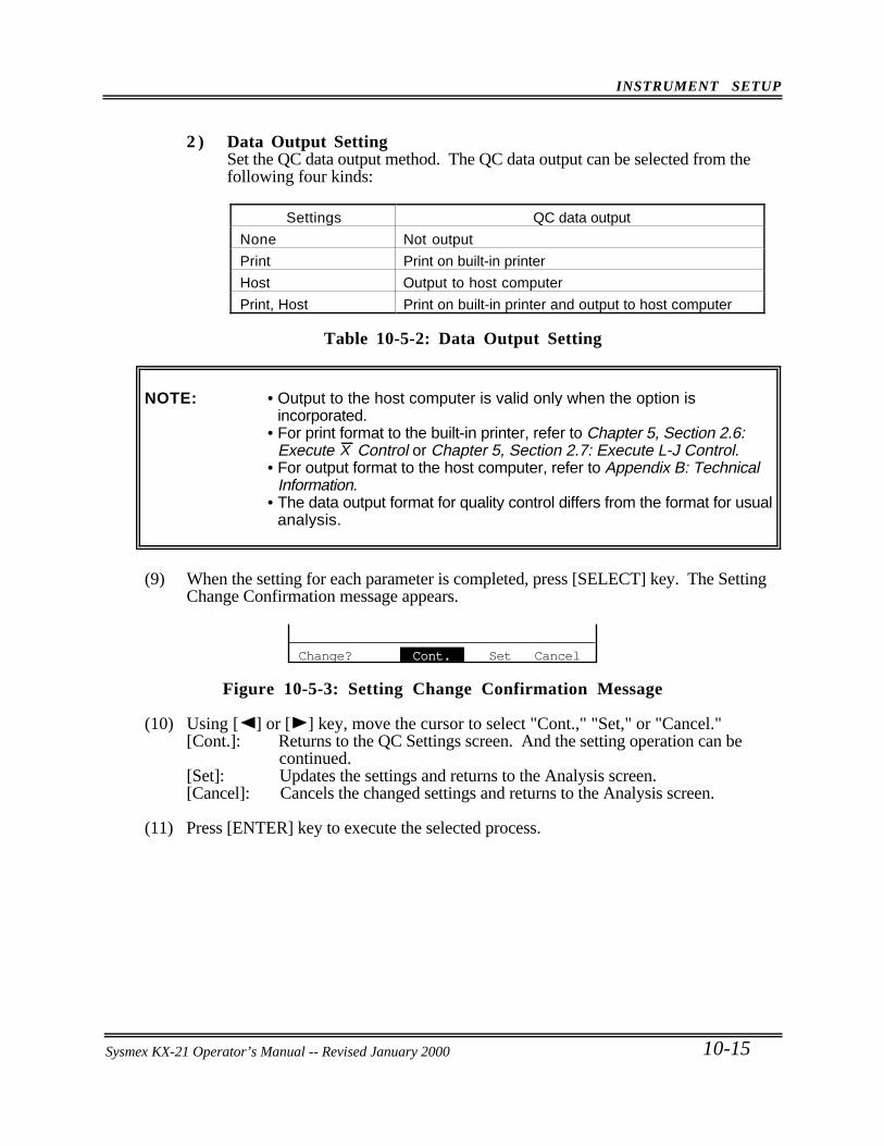
INSTRUMENT SETUP
Sysmex KX-21 Operator’s Manual -- Revised October 1998 10-15
2 ) Data Output SettingSet the QC data output method. The QC data output can be selected from thefollowing four kinds:
Settings QC data output
None Not output
Print Print on built-in printer
Host Output to host computer
Print, Host Print on built-in printer and output to host computer
Table 10-5-2: Data Output Setting
NOTE: • Output to the host computer is valid only when the option isincorporated.
• For print format to the built-in printer, refer to Chapter 5, Section 2.6:Execute X Control or Chapter 5, Section 2.7: Execute L-J Control.
• For output format to the host computer, refer to Appendix B: TechnicalInformation.
• The data output format for quality control differs from the format for usualanalysis.
(9) When the setting for each parameter is completed, press [SELECT] key. The SettingChange Confirmation message appears.
Change? Cont. Set Cancel
Figure 10-5-3: Setting Change Confirmation Message
(10) Using [ ] or [ ] key, move the cursor to select "Cont.," "Set," or "Cancel."[Cont.]: Returns to the QC Settings screen. And the setting operation can be
continued.[Set]: Updates the settings and returns to the Analysis screen.[Cancel]: Cancels the changed settings and returns to the Analysis screen.
(11) Press [ENTER] key to execute the selected process.
Sysmex KX-21 Operator’s Manual -- Revised January 2000
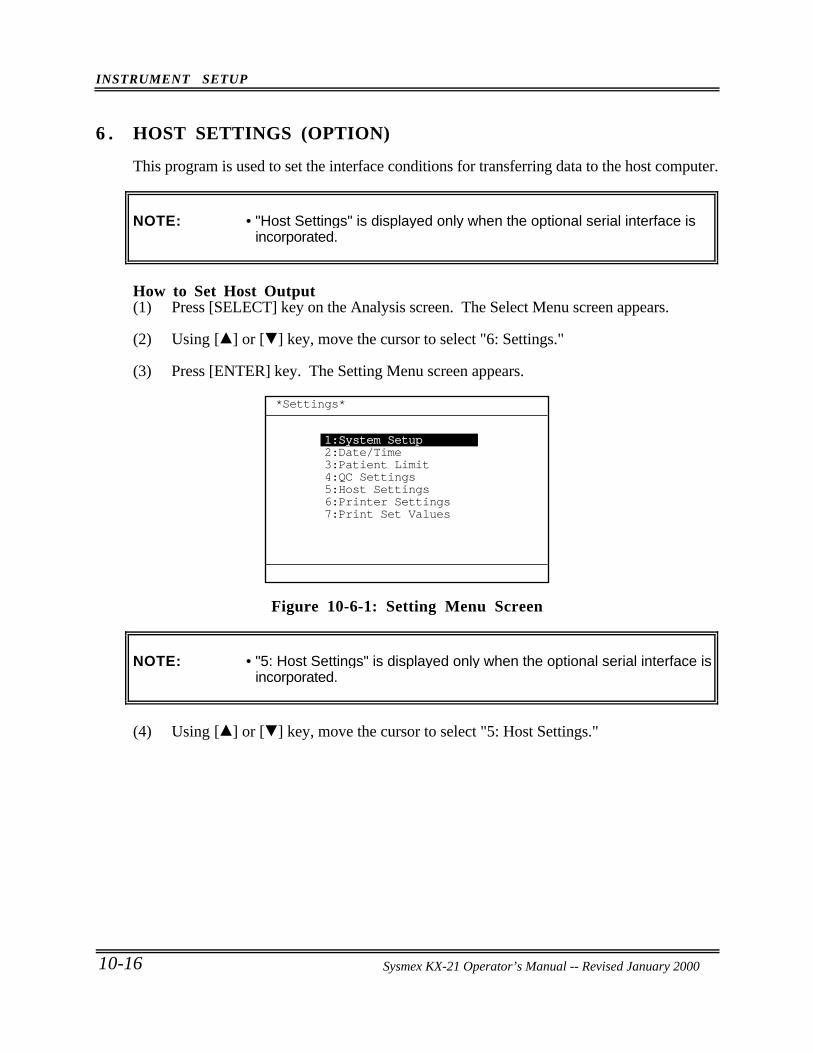
INSTRUMENT SETUP
10-16 Sysmex KX-21 Operator’s Manual -- Revised October 1998
6 . HOST SETTINGS (OPTION)
This program is used to set the interface conditions for transferring data to the host computer.
NOTE: • "Host Settings" is displayed only when the optional serial interface isincorporated.
How to Set Host Output(1) Press [SELECT] key on the Analysis screen. The Select Menu screen appears.
(2) Using [ ] or [ ] key, move the cursor to select "6: Settings."
(3) Press [ENTER] key. The Setting Menu screen appears.
*Settings*
1:System Setup2:Date/Time3:Patient Limit4:QC Settings5:Host Settings6:Printer Settings7:Print Set Values
Figure 10-6-1: Setting Menu Screen
NOTE: • "5: Host Settings" is displayed only when the optional serial interface isincorporated.
(4) Using [ ] or [ ] key, move the cursor to select "5: Host Settings."
Sysmex KX-21 Operator’s Manual -- Revised January 2000
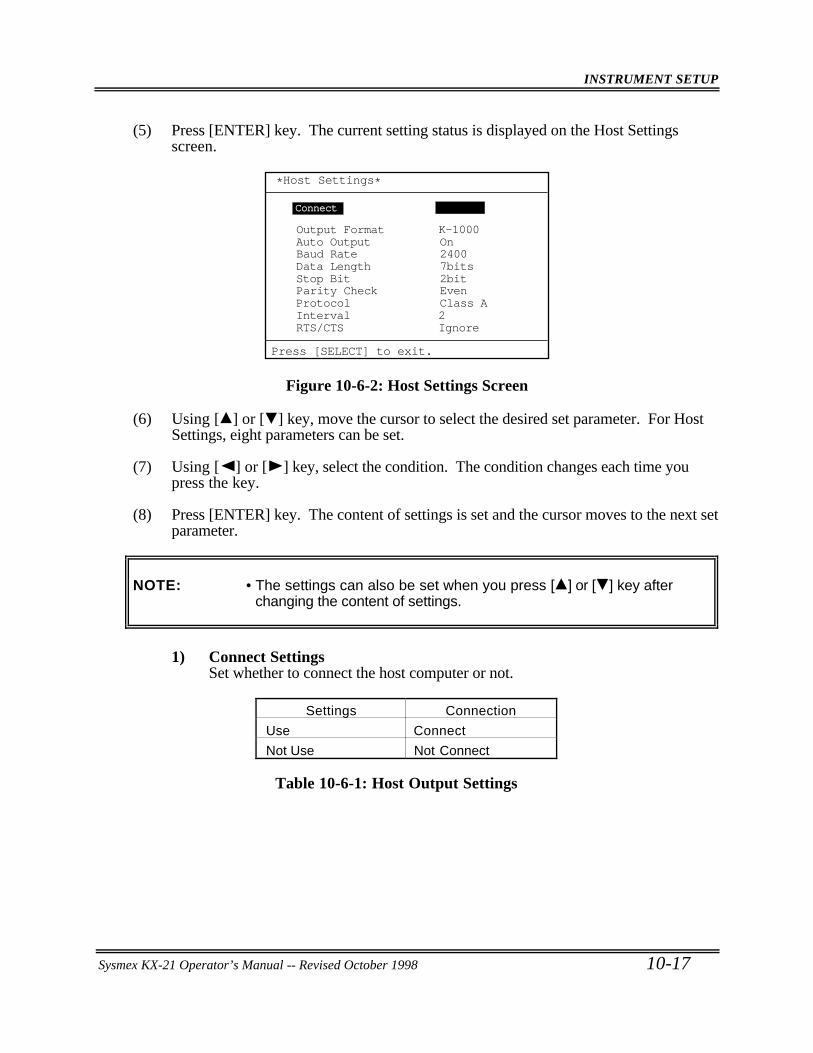
INSTRUMENT SETUP
Sysmex KX-21 Operator’s Manual -- Revised October 1998 10-17
(5) Press [ENTER] key. The current setting status is displayed on the Host Settingsscreen.
Auto Output OnOutput Format K-1000
Data Length 7bitsBaud Rate 2400
Stop Bit 2bit
Protocol Class AInterval 2RTS/CTS Ignore
Parity Check Even
*Host Settings*
Press [SELECT] to exit.
ConnectConnect Not UseNot Use
Figure 10-6-2: Host Settings Screen
(6) Using [ ] or [ ] key, move the cursor to select the desired set parameter. For HostSettings, eight parameters can be set.
(7) Using [ ] or [ ] key, select the condition. The condition changes each time youpress the key.
(8) Press [ENTER] key. The content of settings is set and the cursor moves to the next setparameter.
NOTE: • The settings can also be set when you press [ ] or [ ] key afterchanging the content of settings.
1) Connect SettingsSet whether to connect the host computer or not.
Settings Connection
Use Connect
Not Use Not Connect
Table 10-6-1: Host Output Settings
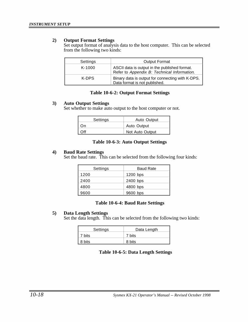
INSTRUMENT SETUP
10-18 Sysmex KX-21 Operator’s Manual -- Revised October 1998
2) Output Format SettingsSet output format of analysis data to the host computer. This can be selectedfrom the following two kinds:
Settings Output Format
K-1000 ASCII data is output in the published format.Refer to Appendix B: Technical Information.
K-DPS Binary data is output for connecting with K-DPS.Data format is not published.
Table 10-6-2: Output Format Settings
3) Auto Output SettingsSet whether to make auto output to the host computer or not.
Settings Auto Output
On Auto Output
Off Not Auto Output
Table 10-6-3: Auto Output Settings
4) Baud Rate SettingsSet the baud rate. This can be selected from the following four kinds:
Settings Baud Rate
1200 1200 bps
2400 2400 bps
4800 4800 bps
9600 9600 bps
Table 10-6-4: Baud Rate Settings
5) Data Length SettingsSet the data length. This can be selected from the following two kinds:
Settings Data Length
7 bits 7 bits
8 bits 8 bits
Table 10-6-5: Data Length Settings
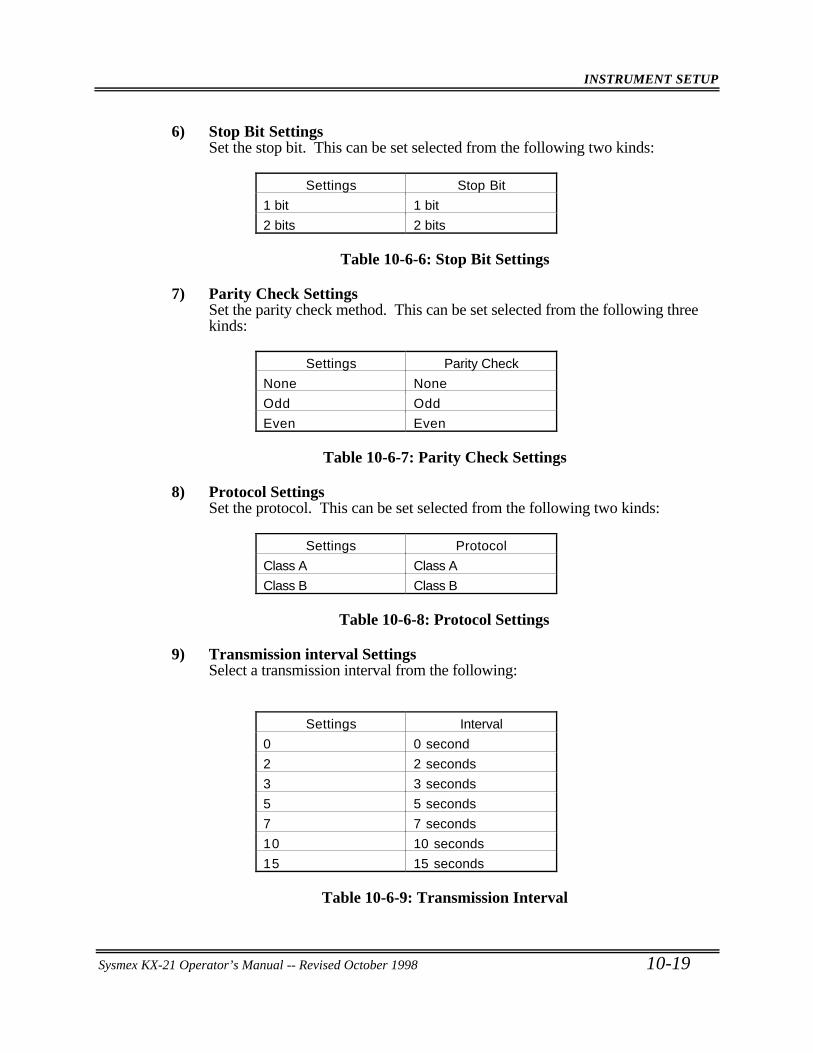
INSTRUMENT SETUP
Sysmex KX-21 Operator’s Manual -- Revised October 1998 10-19
6) Stop Bit SettingsSet the stop bit. This can be set selected from the following two kinds:
Settings Stop Bit
1 bit 1 bit
2 bits 2 bits
Table 10-6-6: Stop Bit Settings
7) Parity Check SettingsSet the parity check method. This can be set selected from the following threekinds:
Settings Parity Check
None None
Odd Odd
Even Even
Table 10-6-7: Parity Check Settings
8) Protocol SettingsSet the protocol. This can be set selected from the following two kinds:
Settings Protocol
Class A Class A
Class B Class B
Table 10-6-8: Protocol Settings
9) Transmission interval SettingsSelect a transmission interval from the following:
Settings Interval
0 0 second
2 2 seconds
3 3 seconds
5 5 seconds
7 7 seconds
10 10 seconds
15 15 seconds
Table 10-6-9: Transmission Interval
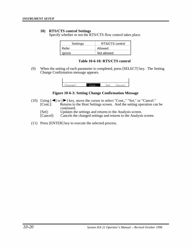
INSTRUMENT SETUP
10-20 Sysmex KX-21 Operator’s Manual -- Revised October 1998
10) RTS/CTS control SettingsSpecify whether or not the RTS/CTS flow control takes place.
Settings RTS/CTS control
Refer Allowed
Ignore Not allowed
Table 10-6-10: RTS/CTS control
(9) When the setting of each parameter is completed, press [SELECT] key. The SettingChange Confirmation message appears.
Change? Cont. Set Cancel
Figure 10-6-3: Setting Change Confirmation Message
(10) Using [ ] or [ ] key, move the cursor to select "Cont.," "Set," or "Cancel."[Cont.]: Returns to the Host Settings screen. And the setting operation can be
continued.[Set]: Updates the settings and returns to the Analysis screen.[Cancel]: Cancels the changed settings and returns to the Analysis screen.
(11) Press [ENTER] key to execute the selected process.
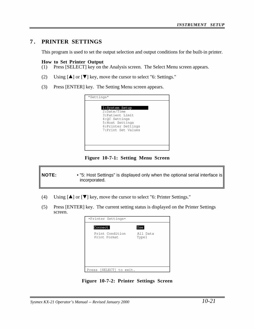
INSTRUMENT SETUP
Sysmex KX-21 Operator’s Manual -- Revised October 1998 10-21
7 . PRINTER SETTINGS
This program is used to set the output selection and output conditions for the built-in printer.
How to Set Printer Output(1) Press [SELECT] key on the Analysis screen. The Select Menu screen appears.
(2) Using [ ] or [ ] key, move the cursor to select "6: Settings."
(3) Press [ENTER] key. The Setting Menu screen appears.
*Settings*
1:System Setup2:Date/Time3:Patient Limit4:QC Settings5:Host Settings6:Printer Settings7:Print Set Values
Figure 10-7-1: Setting Menu Screen
NOTE: • "5: Host Settings" is displayed only when the optional serial interface isincorporated.
(4) Using [ ] or [ ] key, move the cursor to select "6: Printer Settings."
(5) Press [ENTER] key. The current setting status is displayed on the Printer Settingsscreen.
Print Format Type1
Press [SELECT] to exit.
*Printer Settings*
Print Condition All Data
Connect Use
Figure 10-7-2: Printer Settings Screen
Sysmex KX-21 Operator’s Manual -- Revised January 2000
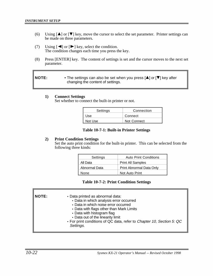
INSTRUMENT SETUP
10-22 Sysmex KX-21 Operator’s Manual -- Revised October 1998
(6) Using [ ] or [ ] key, move the cursor to select the set parameter. Printer settings canbe made on three parameters.
(7) Using [ ] or [ ] key, select the condition.The condition changes each time you press the key.
(8) Press [ENTER] key. The content of settings is set and the cursor moves to the next setparameter.
NOTE: • The settings can also be set when you press [ ] or [ ] key afterchanging the content of settings.
1) Connect SettingsSet whether to connect the built-in printer or not.
Settings Connection
Use Connect
Not Use Not Connect
Table 10-7-1: Built-in Printer Settings
2) Print Condition SettingsSet the auto print condition for the built-in printer. This can be selected from thefollowing three kinds:
Settings Auto Print Conditions
All Data Print All Samples
Abnormal Data Print Abnormal Data Only
None Not Auto Print
Table 10-7-2: Print Condition Settings
NOTE: • Data printed as abnormal data:• Data in which analysis error occurred• Data in which noise error occurred• Data with flags other than Mark Limits• Data with histogram flag• Data out of the linearity limit
• For print conditions of QC data, refer to Chapter 10, Section 5: QCSettings.
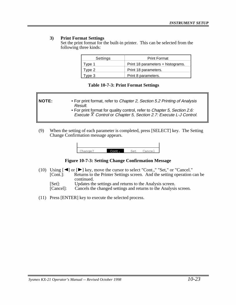
INSTRUMENT SETUP
Sysmex KX-21 Operator’s Manual -- Revised October 1998 10-23
3) Print Format SettingsSet the print format for the built-in printer. This can be selected from thefollowing three kinds:
Settings Print Format
Type 1 Print 18 parameters + histograms.
Type 2 Print 18 parameters.
Type 3 Print 8 parameters.
Table 10-7-3: Print Format Settings
NOTE: • For print format, refer to Chapter 2, Section 5.2 Printing of AnalysisResult.
• For print format for quality control, refer to Chapter 5, Section 2.6:Execute X Control or Chapter 5, Section 2.7: Execute L-J Control.
(9) When the setting of each parameter is completed, press [SELECT] key. The SettingChange Confirmation message appears.
Change? Cont. Set Cancel
Figure 10-7-3: Setting Change Confirmation Message
(10) Using [ ] or [ ] key, move the cursor to select "Cont.," "Set," or "Cancel."[Cont.]: Returns to the Printer Settings screen. And the setting operation can be
continued.[Set]: Updates the settings and returns to the Analysis screen.[Cancel]: Cancels the changed settings and returns to the Analysis screen.
(11) Press [ENTER] key to execute the selected process.
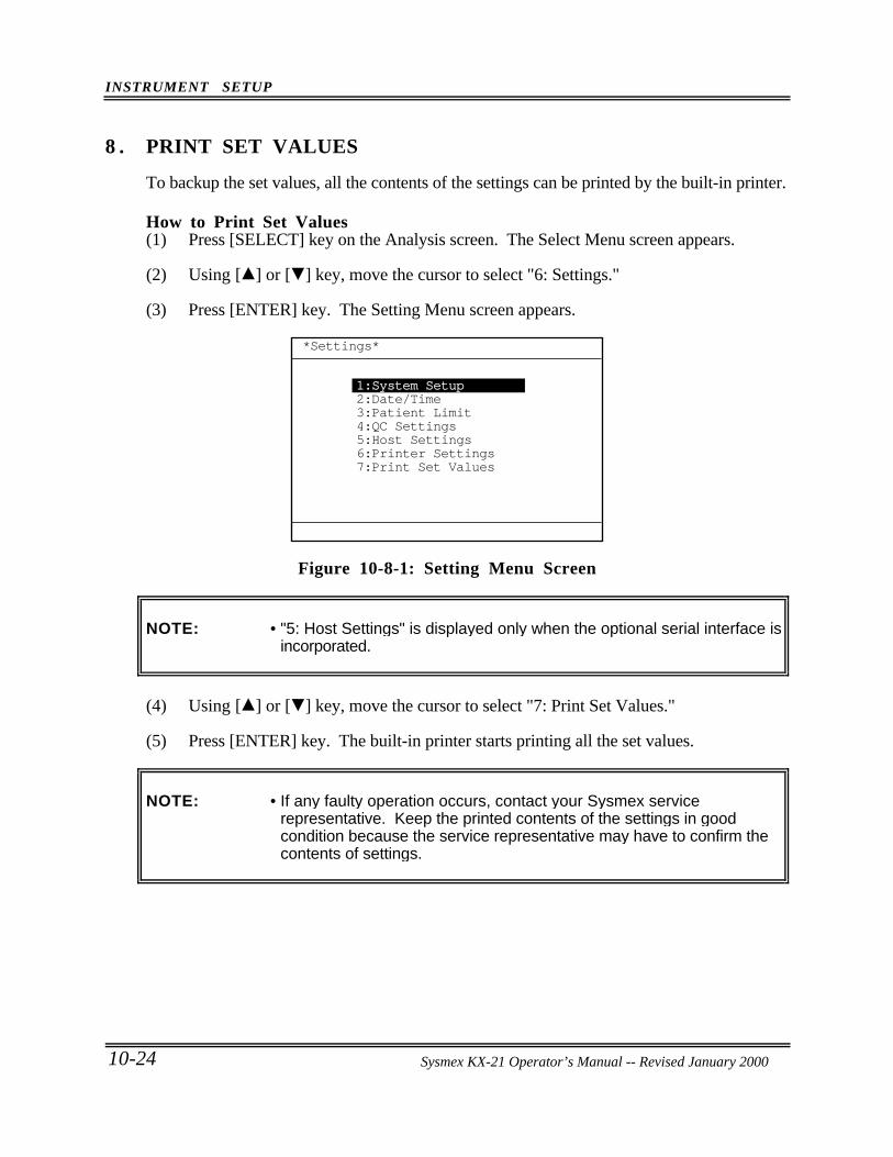
INSTRUMENT SETUP
10-24 Sysmex KX-21 Operator’s Manual -- Revised October 1998
8 . PRINT SET VALUES
To backup the set values, all the contents of the settings can be printed by the built-in printer.
How to Print Set Values(1) Press [SELECT] key on the Analysis screen. The Select Menu screen appears.
(2) Using [ ] or [ ] key, move the cursor to select "6: Settings."
(3) Press [ENTER] key. The Setting Menu screen appears.
*Settings*
1:System Setup2:Date/Time3:Patient Limit4:QC Settings5:Host Settings6:Printer Settings7:Print Set Values
Figure 10-8-1: Setting Menu Screen
NOTE: • "5: Host Settings" is displayed only when the optional serial interface isincorporated.
(4) Using [ ] or [ ] key, move the cursor to select "7: Print Set Values."
(5) Press [ENTER] key. The built-in printer starts printing all the set values.
NOTE: • If any faulty operation occurs, contact your Sysmex servicerepresentative. Keep the printed contents of the settings in goodcondition because the service representative may have to confirm thecontents of settings.
Sysmex KX-21 Operator’s Manual -- Revised January 2000
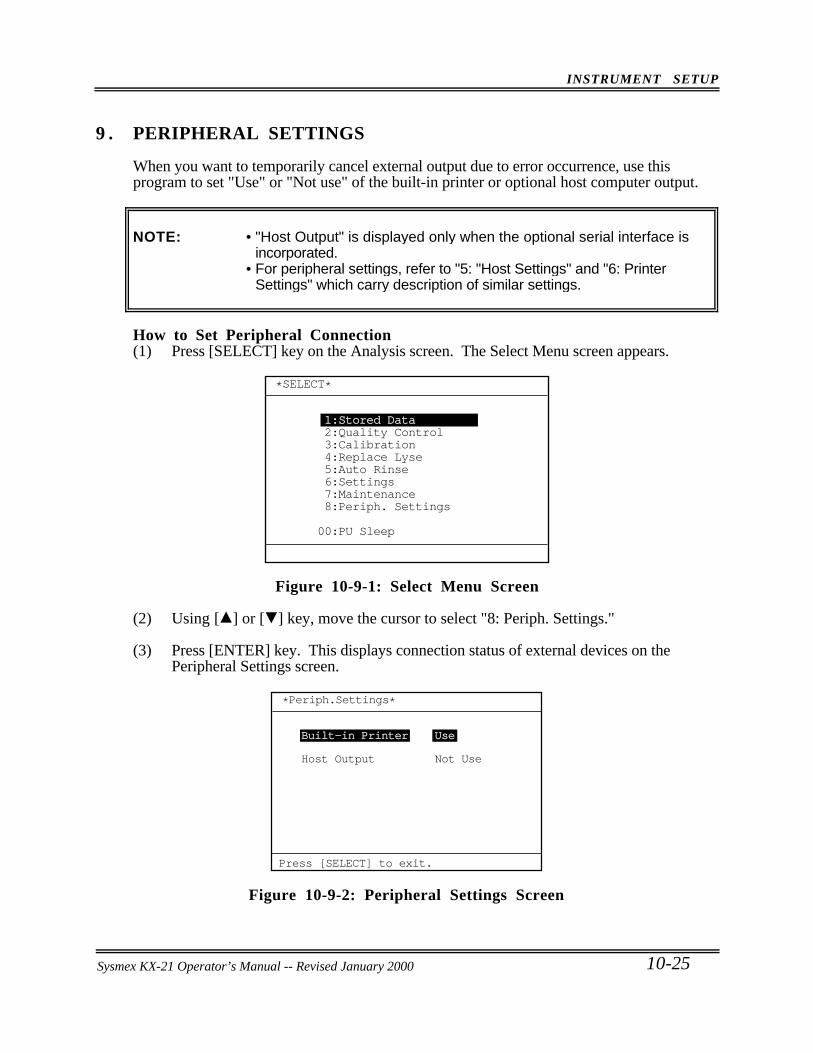
INSTRUMENT SETUP
Sysmex KX-21 Operator’s Manual -- Revised October 1998 10-25
9 . PERIPHERAL SETTINGS
When you want to temporarily cancel external output due to error occurrence, use thisprogram to set "Use" or "Not use" of the built-in printer or optional host computer output.
NOTE: • "Host Output" is displayed only when the optional serial interface isincorporated.
• For peripheral settings, refer to "5: "Host Settings" and "6: PrinterSettings" which carry description of similar settings.
How to Set Peripheral Connection(1) Press [SELECT] key on the Analysis screen. The Select Menu screen appears.
*SELECT*
1:Stored Data2:Quality Control3:Calibration4:Replace Lyse5:Auto Rinse6:Settings7:Maintenance8:Periph. Settings
00:PU Sleep
Figure 10-9-1: Select Menu Screen
(2) Using [ ] or [ ] key, move the cursor to select "8: Periph. Settings."
(3) Press [ENTER] key. This displays connection status of external devices on thePeripheral Settings screen.
*Periph.Settings*
Built-in Printer Use
Host Output Not Use
Press [SELECT] to exit.
Figure 10-9-2: Peripheral Settings Screen
Sysmex KX-21 Operator’s Manual -- Revised January 2000
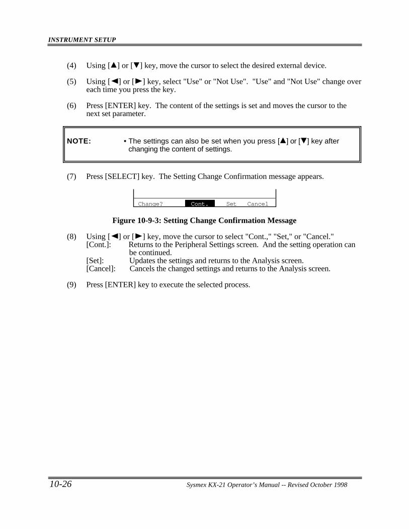
INSTRUMENT SETUP
10-26 Sysmex KX-21 Operator’s Manual -- Revised October 1998
(4) Using [ ] or [ ] key, move the cursor to select the desired external device.
(5) Using [ ] or [ ] key, select "Use" or "Not Use". "Use" and "Not Use" change overeach time you press the key.
(6) Press [ENTER] key. The content of the settings is set and moves the cursor to thenext set parameter.
NOTE: • The settings can also be set when you press [ ] or [ ] key afterchanging the content of settings.
(7) Press [SELECT] key. The Setting Change Confirmation message appears.
Change? Cont. Set Cancel
Figure 10-9-3: Setting Change Confirmation Message
(8) Using [ ] or [ ] key, move the cursor to select "Cont.," "Set," or "Cancel."[Cont.]: Returns to the Peripheral Settings screen. And the setting operation can
be continued.[Set]: Updates the settings and returns to the Analysis screen.[Cancel]: Cancels the changed settings and returns to the Analysis screen.
(9) Press [ENTER] key to execute the selected process.
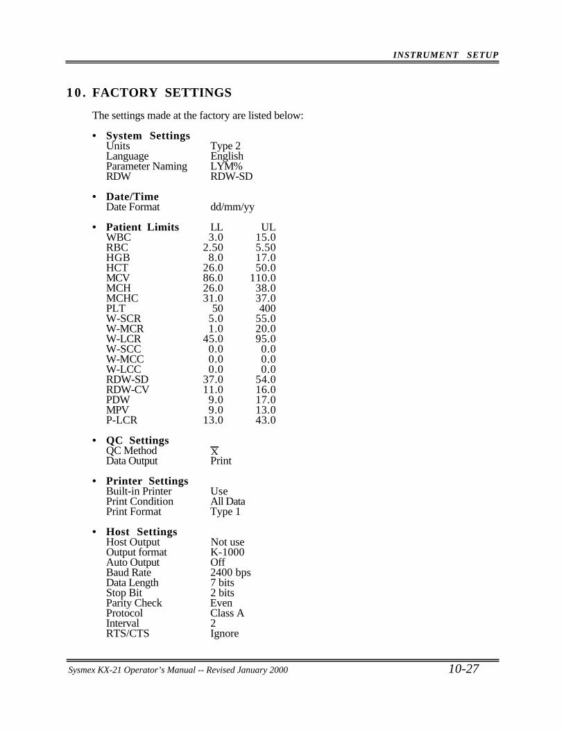
INSTRUMENT SETUP
Sysmex KX-21 Operator’s Manual -- Revised October 1998 10-27
10 . FACTORY SETTINGS
The settings made at the factory are listed below:
• System SettingsUnits Type 2Language EnglishParameter Naming LYM%RDW RDW-SD
• Date/TimeDate Format dd/mm/yy
• Patient Limits LL ULWBC 3.0 15.0RBC 2.50 5.50HGB 8.0 17.0HCT 26.0 50.0MCV 86.0 110.0MCH 26.0 38.0MCHC 31.0 37.0PLT 50 400W-SCR 5.0 55.0W-MCR 1.0 20.0W-LCR 45.0 95.0W-SCC 0.0 0.0W-MCC 0.0 0.0W-LCC 0.0 0.0RDW-SD 37.0 54.0RDW-CV 11.0 16.0PDW 9.0 17.0MPV 9.0 13.0P-LCR 13.0 43.0
• QC SettingsQC Method XData Output Print
• Printer SettingsBuilt-in Printer UsePrint Condition All DataPrint Format Type 1
• Host SettingsHost Output Not useOutput format K-1000Auto Output OffBaud Rate 2400 bpsData Length 7 bitsStop Bit 2 bitsParity Check EvenProtocol Class AInterval 2RTS/CTS Ignore
Sysmex KX-21 Operator’s Manual -- Revised January 2000
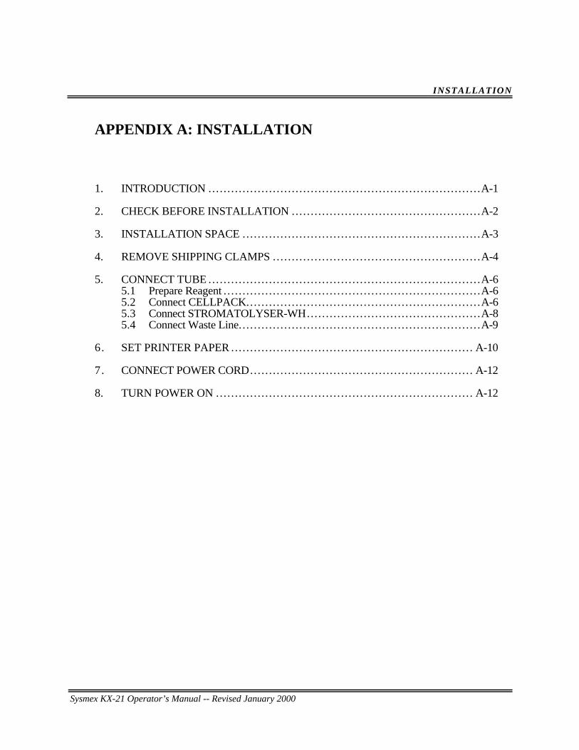
Sysmex KX-21 Operator’s Manual -- Revised January 2000
INSTALLATION
APPENDIX A: INSTALLATION
1. INTRODUCTION ... . . . . . . . . . . . . . . . . . . . . . . . . . . . . . . . . . . . . . . . . . . . . . . . . . . . . . . . . . . . . . . . . . . . . .A-1
2. CHECK BEFORE INSTALLATION ... . . . . . . . . . . . . . . . . . . . . . . . . . . . . . . . . . . . . . . . . . . . . . . .A-2
3. INSTALLATION SPACE ... . . . . . . . . . . . . . . . . . . . . . . . . . . . . . . . . . . . . . . . . . . . . . . . . . . . . . . . . . . . .A-3
4. REMOVE SHIPPING CLAMPS ... . . . . . . . . . . . . . . . . . . . . . . . . . . . . . . . . . . . . . . . . . . . . . . . . . . . .A-4
5. CONNECT TUBE ... . . . . . . . . . . . . . . . . . . . . . . . . . . . . . . . . . . . . . . . . . . . . . . . . . . . . . . . . . . . . . . . . . . . . .A-65.1 Prepare Reagent .. . . . . . . . . . . . . . . . . . . . . . . . . . . . . . . . . . . . . . . . . . . . . . . . . . . . . . . . . . . . . . . . . . .A-65.2 Connect CELLPACK... . . . . . . . . . . . . . . . . . . . . . . . . . . . . . . . . . . . . . . . . . . . . . . . . . . . . . . . . . . .A-65.3 Connect STROMATOLYSER-WH.... . . . . . . . . . . . . . . . . . . . . . . . . . . . . . . . . . . . . . . . . . .A-85.4 Connect Waste Line.. . . . . . . . . . . . . . . . . . . . . . . . . . . . . . . . . . . . . . . . . . . . . . . . . . . . . . . . . . . . . . .A-9
6. SET PRINTER PAPER ... . . . . . . . . . . . . . . . . . . . . . . . . . . . . . . . . . . . . . . . . . . . . . . . . . . . . . . . . . . . . . A-10
7. CONNECT POWER CORD... . . . . . . . . . . . . . . . . . . . . . . . . . . . . . . . . . . . . . . . . . . . . . . . . . . . . . . . . A-12
8. TURN POWER ON ... . . . . . . . . . . . . . . . . . . . . . . . . . . . . . . . . . . . . . . . . . . . . . . . . . . . . . . . . . . . . . . . . . A-12
INSTALLATION
Sysmex KX-21 Operator’s Manual -- Revised October 1998 A -1
1 . INTRODUCTION
This product is a clinical test instrument. Sysmex representative is responsible forunpacking, installing, and initial setup of the product to ensure its proper and safe operation.The next several pages will give some essential information on this instrument.
NOTE: • When the optional serial interface function is intended to incorporate tothis instrument, following optional part should be ordered in prior to theinstallation so that Sysmex service representative could install at once.
973-4531-1 OUTPUT UNIT NO. 1 KX-21
Sysmex KX-21 Operator’s Manual -- Revised January 2000
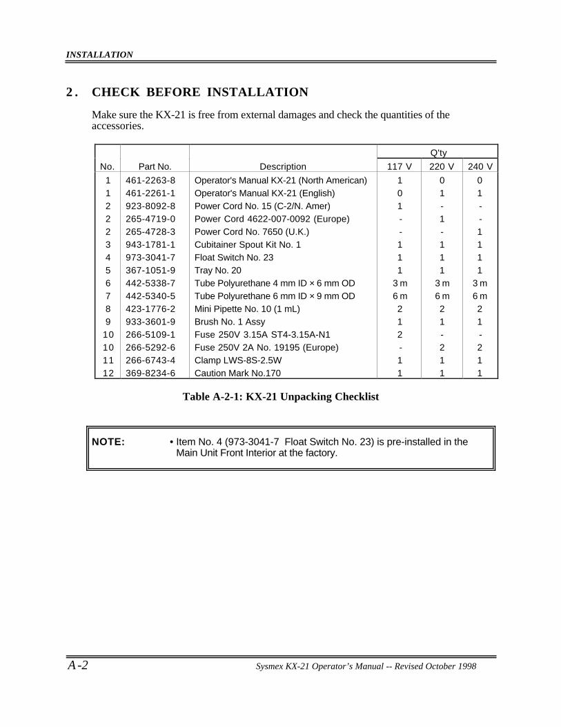
INSTALLATION
A -2 Sysmex KX-21 Operator’s Manual -- Revised October 1998
2 . CHECK BEFORE INSTALLATION
Make sure the KX-21 is free from external damages and check the quantities of theaccessories.
Q'ty
No. Part No. Description 117 V 220 V 240 V
112223456789
10101112
461-2263-8461-2261-1923-8092-8265-4719-0265-4728-3943-1781-1973-3041-7367-1051-9442-5338-7442-5340-5423-1776-2933-3601-9266-5109-1266-5292-6266-6743-4369-8234-6
Operator's Manual KX-21 (North American)Operator's Manual KX-21 (English)Power Cord No. 15 (C-2/N. Amer)Power Cord 4622-007-0092 (Europe)Power Cord No. 7650 (U.K.)Cubitainer Spout Kit No. 1Float Switch No. 23Tray No. 20Tube Polyurethane 4 mm ID × 6 mm ODTube Polyurethane 6 mm ID × 9 mm ODMini Pipette No. 10 (1 mL)Brush No. 1 AssyFuse 250V 3.15A ST4-3.15A-N1Fuse 250V 2A No. 19195 (Europe)Clamp LWS-8S-2.5WCaution Mark No.170
101--111
3 m6 m212-11
01-1-111
3 m6 m21-211
01--1111
3 m6 m21-211
Table A-2-1: KX-21 Unpacking Checklist
NOTE: • Item No. 4 (973-3041-7 Float Switch No. 23) is pre-installed in theMain Unit Front Interior at the factory.
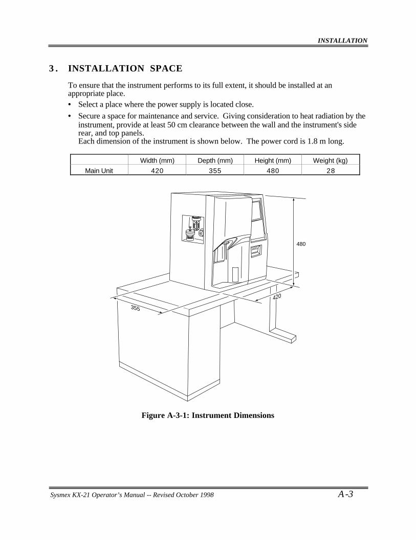
INSTALLATION
Sysmex KX-21 Operator’s Manual -- Revised October 1998 A -3
3 . INSTALLATION SPACE
To ensure that the instrument performs to its full extent, it should be installed at anappropriate place.• Select a place where the power supply is located close.
• Secure a space for maintenance and service. Giving consideration to heat radiation by theinstrument, provide at least 50 cm clearance between the wall and the instrument's siderear, and top panels.Each dimension of the instrument is shown below. The power cord is 1.8 m long.
Width (mm) Depth (mm) Height (mm) Weight (kg)
Main Unit 420 355 480 28
480
355
420
Figure A-3-1: Instrument Dimensions
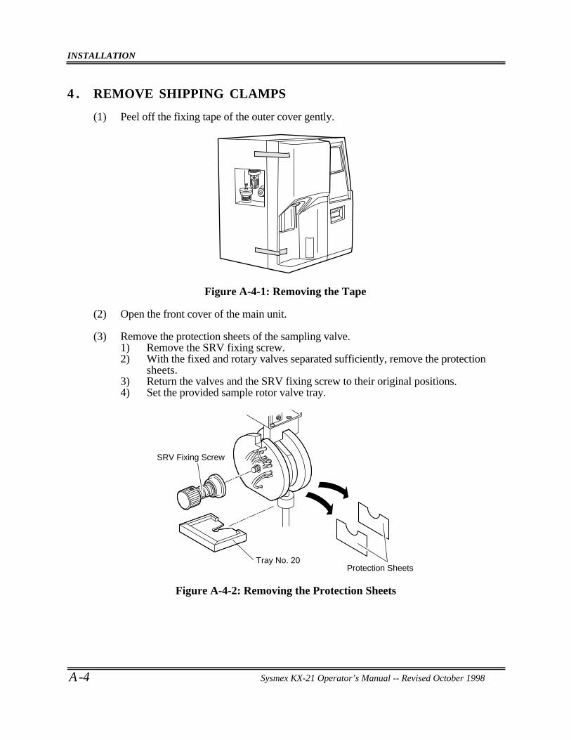
INSTALLATION
A -4 Sysmex KX-21 Operator’s Manual -- Revised October 1998
4 . REMOVE SHIPPING CLAMPS
(1) Peel off the fixing tape of the outer cover gently.
Figure A-4-1: Removing the Tape
(2) Open the front cover of the main unit.
(3) Remove the protection sheets of the sampling valve.1) Remove the SRV fixing screw.2) With the fixed and rotary valves separated sufficiently, remove the protection
sheets.3) Return the valves and the SRV fixing screw to their original positions.4) Set the provided sample rotor valve tray.
Protection Sheets
SRV Fixing Screw
Tray No. 20
Figure A-4-2: Removing the Protection Sheets
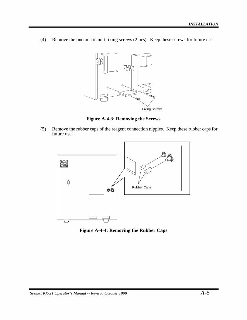
INSTALLATION
Sysmex KX-21 Operator’s Manual -- Revised October 1998 A -5
(4) Remove the pneumatic unit fixing screws (2 pcs). Keep these screws for future use.
Fixing Screws
Figure A-4-3: Removing the Screws
(5) Remove the rubber caps of the reagent connection nipples. Keep these rubber caps forfuture use.
Rubber Caps
Figure A-4-4: Removing the Rubber Caps
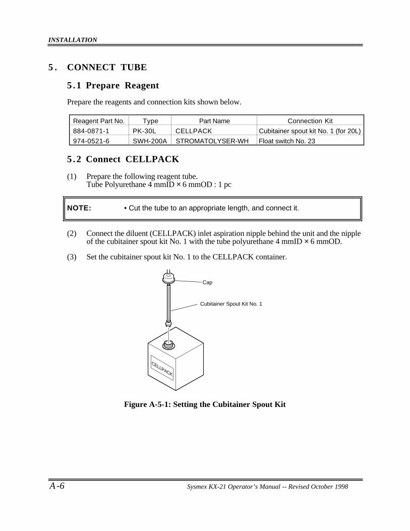
INSTALLATION
A -6 Sysmex KX-21 Operator’s Manual -- Revised October 1998
5 . CONNECT TUBE
5 .1 Prepare Reagent
Prepare the reagents and connection kits shown below.
Reagent Part No. Type Part Name Connection Kit
884-0871-1 PK-30L CELLPACK Cubitainer spout kit No. 1 (for 20L)
974-0521-6 SWH-200A STROMATOLYSER-WH Float switch No. 23
5 .2 Connect CELLPACK
(1) Prepare the following reagent tube.Tube Polyurethane 4 mmID × 6 mmOD : 1 pc
NOTE: • Cut the tube to an appropriate length, and connect it.
(2) Connect the diluent (CELLPACK) inlet aspiration nipple behind the unit and the nippleof the cubitainer spout kit No. 1 with the tube polyurethane 4 mmID × 6 mmOD.
(3) Set the cubitainer spout kit No. 1 to the CELLPACK container.
CELLPACK
Cap
Cubitainer Spout Kit No. 1
Figure A-5-1: Setting the Cubitainer Spout Kit
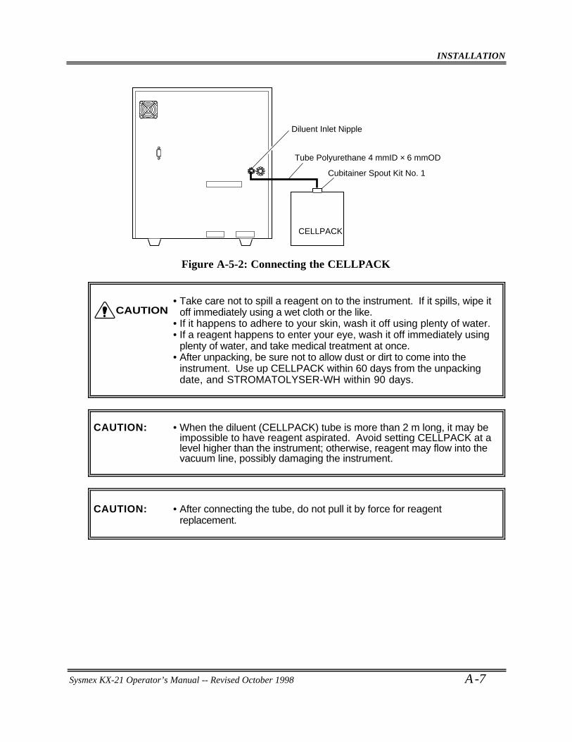
INSTALLATION
Sysmex KX-21 Operator’s Manual -- Revised October 1998 A -7
Tube Polyurethane 4 mmID × 6 mmOD
Diluent Inlet Nipple
Cubitainer Spout Kit No. 1
CELLPACK
Figure A-5-2: Connecting the CELLPACK
• Take care not to spill a reagent on to the instrument. If it spills, wipe itoff immediately using a wet cloth or the like.
• If it happens to adhere to your skin, wash it off using plenty of water.• If a reagent happens to enter your eye, wash it off immediately using
plenty of water, and take medical treatment at once.• After unpacking, be sure not to allow dust or dirt to come into the
instrument. Use up CELLPACK within 60 days from the unpackingdate, and STROMATOLYSER-WH within 90 days.
CAUTION: • When the diluent (CELLPACK) tube is more than 2 m long, it may beimpossible to have reagent aspirated. Avoid setting CELLPACK at alevel higher than the instrument; otherwise, reagent may flow into thevacuum line, possibly damaging the instrument.
CAUTION: • After connecting the tube, do not pull it by force for reagentreplacement.
CAUTION
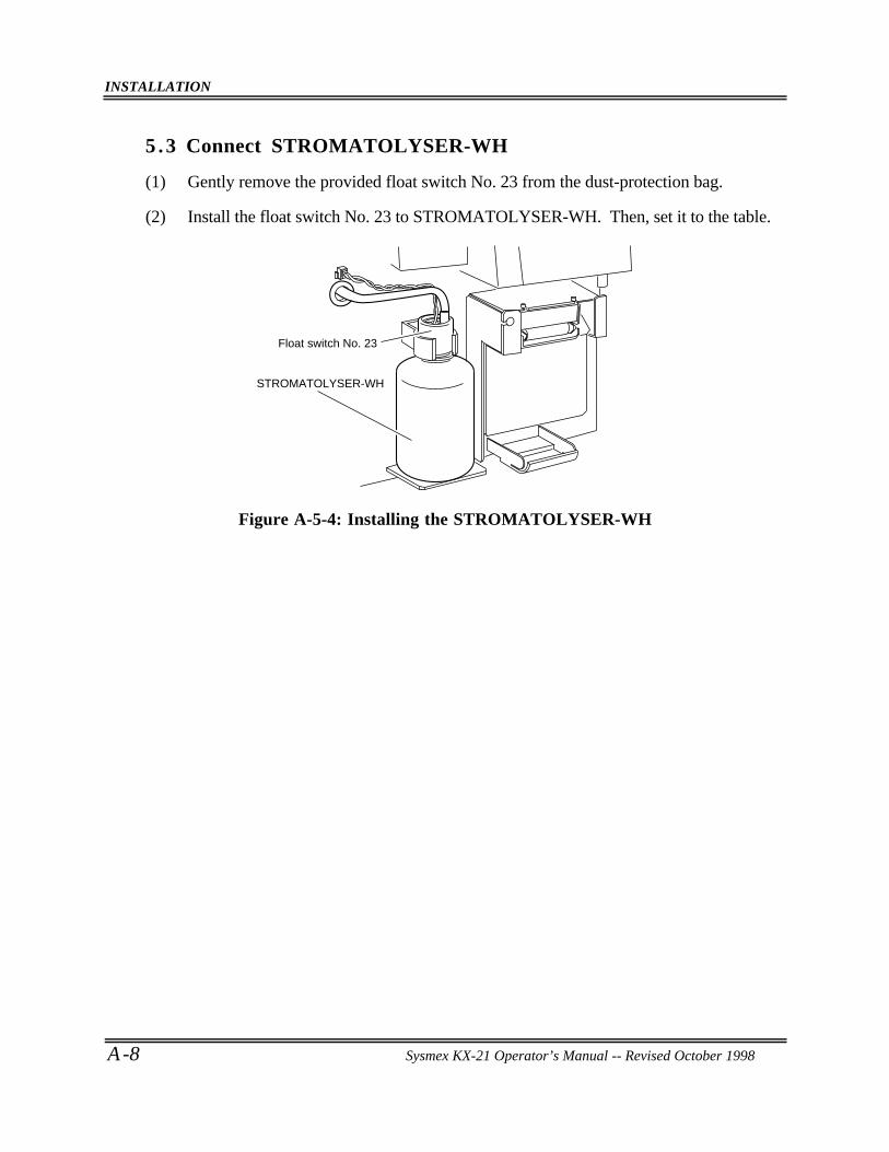
INSTALLATION
A -8 Sysmex KX-21 Operator’s Manual -- Revised October 1998
5 .3 Connect STROMATOLYSER-WH
(1) Gently remove the provided float switch No. 23 from the dust-protection bag.
(2) Install the float switch No. 23 to STROMATOLYSER-WH. Then, set it to the table.
STROMATOLYSER-WH
Float switch No. 23
Figure A-5-4: Installing the STROMATOLYSER-WH
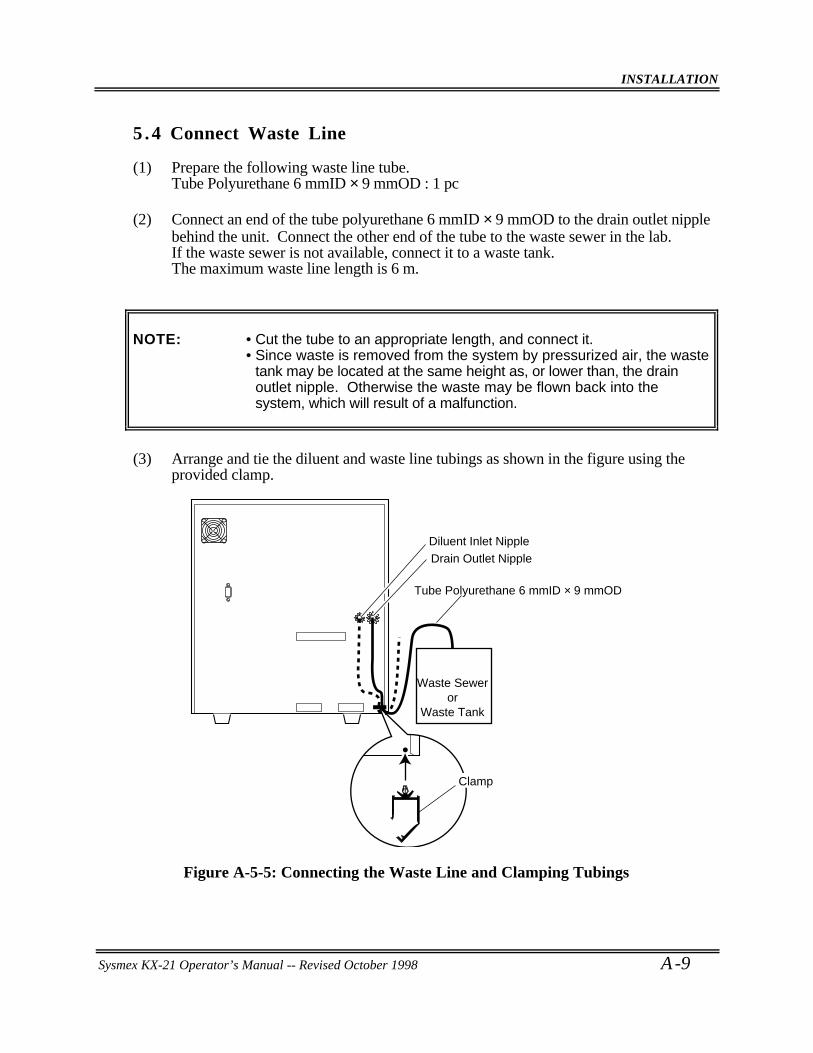
INSTALLATION
Sysmex KX-21 Operator’s Manual -- Revised October 1998 A -9
5 .4 Connect Waste Line
(1) Prepare the following waste line tube.Tube Polyurethane 6 mmID × 9 mmOD : 1 pc
(2) Connect an end of the tube polyurethane 6 mmID × 9 mmOD to the drain outlet nipplebehind the unit. Connect the other end of the tube to the waste sewer in the lab.If the waste sewer is not available, connect it to a waste tank.The maximum waste line length is 6 m.
NOTE: • Cut the tube to an appropriate length, and connect it.• Since waste is removed from the system by pressurized air, the waste
tank may be located at the same height as, or lower than, the drainoutlet nipple. Otherwise the waste may be flown back into thesystem, which will result of a malfunction.
(3) Arrange and tie the diluent and waste line tubings as shown in the figure using theprovided clamp.
Drain Outlet Nipple
Tube Polyurethane 6 mmID × 9 mmOD
Waste Seweror
Waste Tank
Clamp
Diluent Inlet Nipple
Figure A-5-5: Connecting the Waste Line and Clamping Tubings
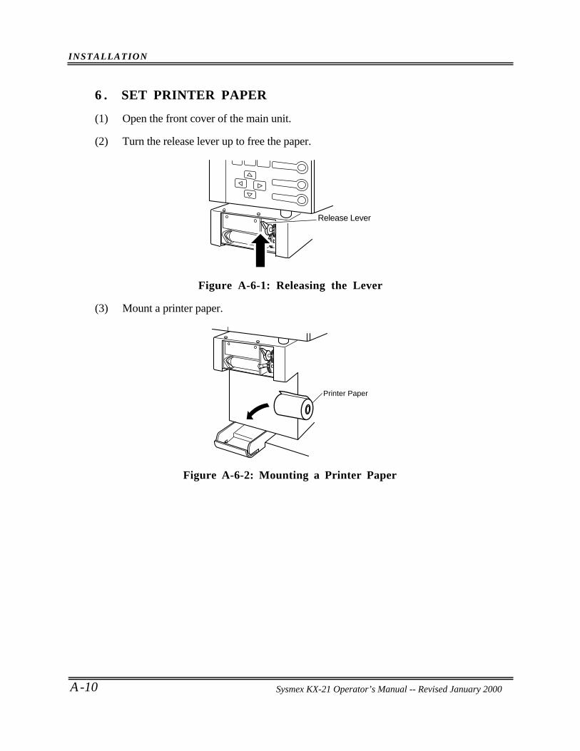
INSTALLATION
A -10 Sysmex KX-21 Operator’s Manual -- Revised October 1998
6 . SET PRINTER PAPER
(1) Open the front cover of the main unit.
(2) Turn the release lever up to free the paper.
Release Lever
Figure A-6-1: Releasing the Lever
(3) Mount a printer paper.
Printer Paper
Figure A-6-2: Mounting a Printer Paper
Sysmex KX-21 Operator’s Manual -- Revised January 2000
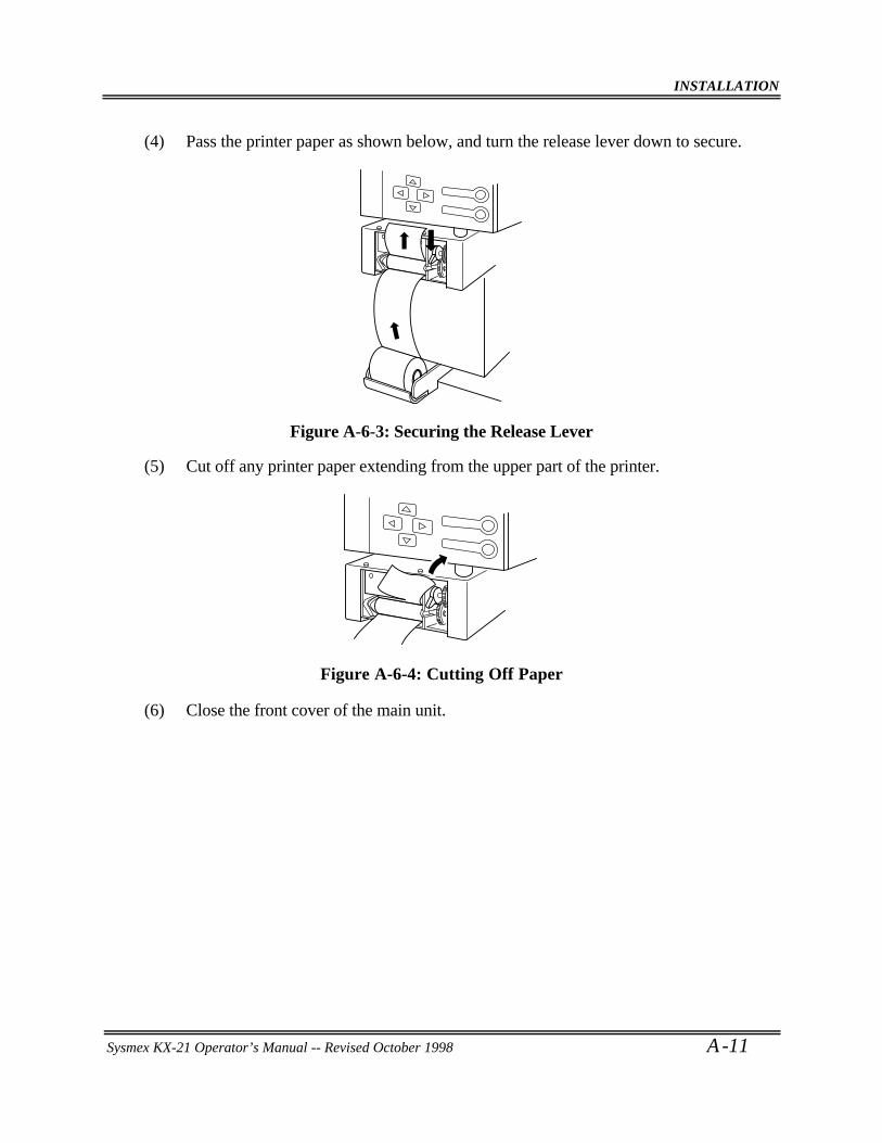
INSTALLATION
Sysmex KX-21 Operator’s Manual -- Revised October 1998 A -11
(4) Pass the printer paper as shown below, and turn the release lever down to secure.
Figure A-6-3: Securing the Release Lever
(5) Cut off any printer paper extending from the upper part of the printer.
Figure A-6-4: Cutting Off Paper
(6) Close the front cover of the main unit.
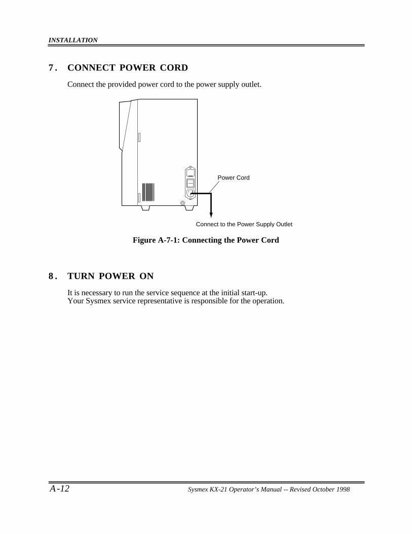
INSTALLATION
A -12 Sysmex KX-21 Operator’s Manual -- Revised October 1998
7 . CONNECT POWER CORD
Connect the provided power cord to the power supply outlet.
Connect to the Power Supply Outlet
Power Cord
Figure A-7-1: Connecting the Power Cord
8 . TURN POWER ON
It is necessary to run the service sequence at the initial start-up.Your Sysmex service representative is responsible for the operation.
Sysmex KX-21 Operator’s Manual -- Revised October 1998
TECHNICAL INFORMATION
APPENDIX B: TECHNICAL INFORMATION
1. OUTPUT FORMAT FOR HOST COMPUTER (OPTION).. . . . . . . . . . . . . . . . . . . . . . . .B-11.1 Hardware.. . . . . . . . . . . . . . . . . . . . . . . . . . . . . . . . . . . . . . . . . . . . . . . . . . . . . . . . . . . . . . . . . . . . . . . . . . .B-11.2 Software.. . . . . . . . . . . . . . . . . . . . . . . . . . . . . . . . . . . . . . . . . . . . . . . . . . . . . . . . . . . . . . . . . . . . . . . . . . . .B-3
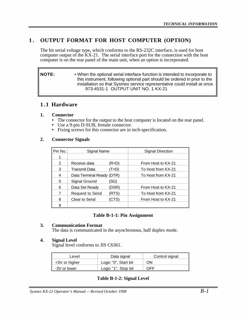
TECHNICAL INFORMATION
Sysmex KX-21 Operator’s Manual -- Revised October 1998 B-1
1 . OUTPUT FORMAT FOR HOST COMPUTER (OPTION)
The bit serial voltage type, which conforms to the RS-232C interface, is used for hostcomputer output of the KX-21. The serial interface port for the connection with the hostcomputer is on the rear panel of the main unit, when an option is incorporated.
NOTE: • When the optional serial interface function is intended to incorporate tothis instrument, following optional part should be ordered in prior to theinstallation so that Sysmex service representative could install at once.
973-4531-1 OUTPUT UNIT NO. 1 KX-21
1 .1 Hardware
1. Connector• The connector for the output to the host computer is located on the rear panel.• Use a 9-pin D-SUB, female connector.• Fixing screws for this connector are in inch-specification.
2. Connector Signals
Pin No. Signal Name Signal Direction
1
2 Receive data (R×D) From Host to KX-21
3 Transmit Data (T×D) To Host from KX-21
4 Data Terminal Ready (DTR) To Host from KX-21
5 Signal Ground (SG)
6 Data Set Ready (DSR) From Host to KX-21
7 Request to Send (RTS) To Host from KX-21
8 Clear to Send (CTS) From Host to KX-21
9
Table B-1-1: Pin Assignment
3. Communication FormatThe data is communicated in the asynchronous, half duplex mode.
4. Signal LevelSignal level conforms to JIS C6361.
Level Data signal Control signal
+3V or higher Logic "0", Start bit ON
-3V or lower Logic "1", Stop bit OFF
Table B-1-2: Signal Level
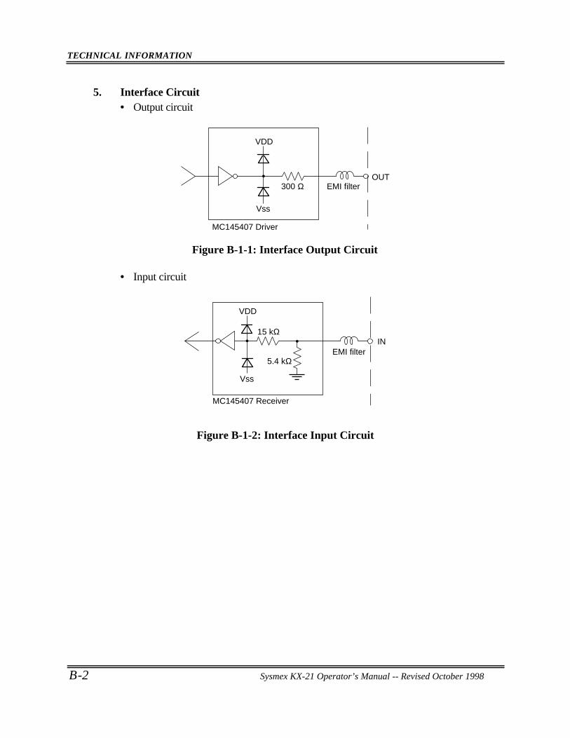
TECHNICAL INFORMATION
B-2 Sysmex KX-21 Operator’s Manual -- Revised October 1998
5. Interface Circuit• Output circuit
300 ΩOUT
EMI filter
MC145407 Driver
Vss
VDD
Figure B-1-1: Interface Output Circuit
• Input circuit
INEMI filter
5.4 kΩ
MC145407 Receiver
15 kΩ
VDD
Vss
Figure B-1-2: Interface Input Circuit
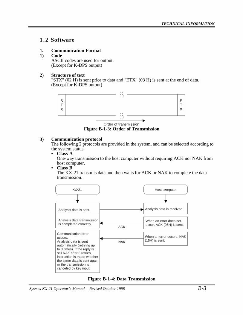
TECHNICAL INFORMATION
Sysmex KX-21 Operator’s Manual -- Revised October 1998 B-3
1 .2 Software
1. Communication Format1) Code
ASCII codes are used for output.(Except for K-DPS output)
2) Structure of text"STX" (02 H) is sent prior to data and "ETX" (03 H) is sent at the end of data.(Except for K-DPS output)
STX
ETX
Order of transmissionFigure B-1-3: Order of Transmission
3) Communication protocolThe following 2 protocols are provided in the system, and can be selected according tothe system status.• Class A
One-way transmission to the host computer without requiring ACK nor NAK fromhost computer.
• Class BThe KX-21 transmits data and then waits for ACK or NAK to complete the datatransmission.
Analysis data is sent.
Analysis data transmission is completed correctly.
Communication error occurs.Analysis data is sent automatically (retrying up to 3 times). If the reply is still NAK after 3 retries, instruction is made whether the same data is sent again or the transmission is canceled by key input.
Analysis data is received.
When an error does not occur, ACK (06H) is sent.
When an error occurs, NAK (15H) is sent.
KX-21 Host computer
ACK
NAK
Figure B-1-4: Data Transmission
TECHNICAL INFORMATION
B-4 Sysmex KX-21 Operator’s Manual -- Revised October 1998
4) Transmission errorsIf the KX-21 detects a transmission error, the data transmission is canceled and anerror message is displayed. Re-transmission of the data ([1] key) or cancellation of thetransmission ([3] key) can be selected. Transmission errors occur in the followingsituations.
• The computer is off line.• The control signal DSR is off.• After the data is transmitted, there is no response from the computer in 15 seconds.
(Class B only)• After the data is transmitted, other than ACK or NAK is sent from the computer.
(Class B only)• After the data is transmitted, the fourth NAK is sent. (Class B only. The KX-21
resends the data automatically up to 3 times when NAK is sent.)
5) Timing, subject, and content of transmission
Serial interface↓
Host computer
Normal analysis Analysis data (A)
Quality control QC data (A)
Table B-1-3: Content of Transmission
• Analysis data includes the date, sample ID No., 18-parameter data, and the flag.• QC data is X or L-J data.• The setting of the connecting device is changed in the setting program.
2. Text FormatThe following two types of formats are used for computer output.• K-1000: Format for connecting to the host computer• K-DPS: Special format for connecting to K-DPS
NOTE: • K-1000 format is selected at the time of shipping from the factory.
The details of K-1000 format are as follows.• K-1000 format
K-1000 format has two formats; one is "analysis data format" for output of thesample data, and the other is "QC data format" for output of the QC data. Theydiffer in length and content of the text. (They are distinguished by the sampledistinction code.)The text distinction code II is fixed at "1".However, when the text exceeds 256 bytes in a future modification, the text isdivided into 2 or more blocks. The number in text distinction code II shows theorder of the blocks. The ETB (17 H) is not used.
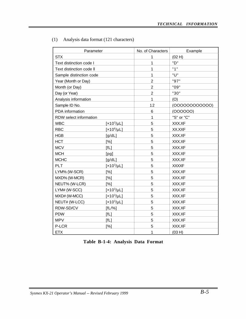
TECHNICAL INFORMATION
Sysmex KX-21 Operator’s Manual -- Revised October 1998 B-5
(1) Analysis data format (121 characters)
Parameter No. of Characters Example
STX 1 (02 H)
Text distinction code I 1 "D"
Text distinction code ll 1 "1"
Sample distinction code 1 "U"
Year (Month or Day) 2 "97"
Month (or Day) 2 "09"
Day (or Year) 2 "30"
Analysis information 1 (O)
Sample ID No. 12 (OOOOOOOOOOOO)
PDA information 6 (OOOOOO)
RDW select information 1 "S" or "C"
WBC [×103/µL] 5 XXX.XF
RBC [×106/µL] 5 XX.XXF
HGB [g/dL] 5 XXX.XF
HCT [%] 5 XXX.XF
MCV [fL] 5 XXX.XF
MCH [pg] 5 XXX.XF
MCHC [g/dL] 5 XXX.XF
PLT [×103/µL] 5 XXXXF
LYM% (W-SCR) [%] 5 XXX.XF
MXD% (W-MCR) [%] 5 XXX.XF
NEUT% (W-LCR) [%] 5 XXX.XF
LYM# (W-SCC) [×103/µL] 5 XXX.XF
MXD# (W-MCC) [×103/µL] 5 XXX.XF
NEUT# (W-LCC) [×103/µL] 5 XXX.XF
RDW-SD/CV [fL/%] 5 XXX.XF
PDW [fL] 5 XXX.XF
MPV [fL] 5 XXX.XF
P-LCR [%] 5 XXX.XF
ETX 1 (03 H)
Table B-1-4: Analysis Data Format
Sysmex KX-21 Operator’s Manual -- Revised February 1999
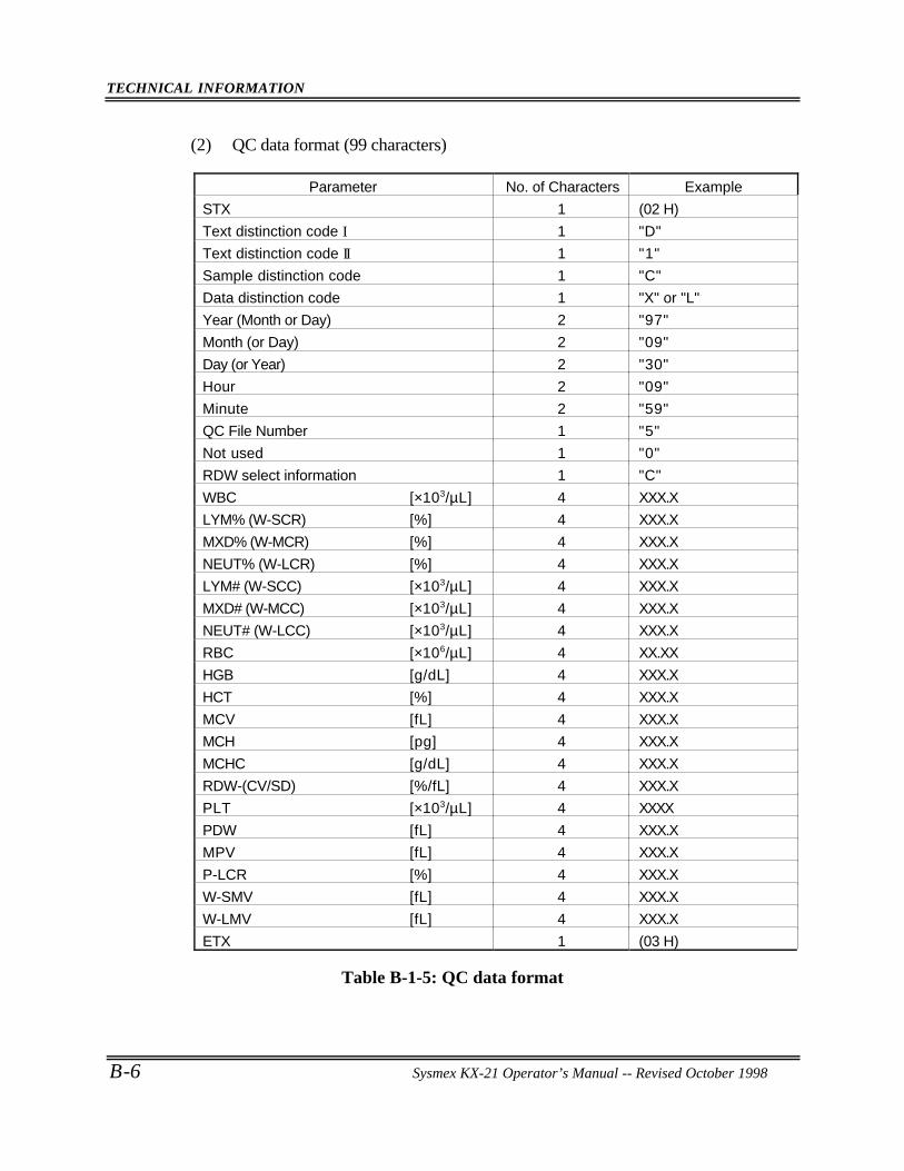
TECHNICAL INFORMATION
B-6 Sysmex KX-21 Operator’s Manual -- Revised October 1998
(2) QC data format (99 characters)
Parameter No. of Characters Example
STX 1 (02 H)
Text distinction code I 1 "D"
Text distinction code II 1 "1"
Sample distinction code 1 "C"
Data distinction code 1 "X" or "L"
Year (Month or Day) 2 "97"
Month (or Day) 2 "09"
Day (or Year) 2 "30"
Hour 2 "09"
Minute 2 "59"
QC File Number 1 "5"
Not used 1 "0"
RDW select information 1 "C"
WBC [×103/µL] 4 XXX.X
LYM% (W-SCR) [%] 4 XXX.X
MXD% (W-MCR) [%] 4 XXX.X
NEUT% (W-LCR) [%] 4 XXX.X
LYM# (W-SCC) [×103/µL] 4 XXX.X
MXD# (W-MCC) [×103/µL] 4 XXX.X
NEUT# (W-LCC) [×103/µL] 4 XXX.X
RBC [×106/µL] 4 XX.XX
HGB [g/dL] 4 XXX.X
HCT [%] 4 XXX.X
MCV [fL] 4 XXX.X
MCH [pg] 4 XXX.X
MCHC [g/dL] 4 XXX.X
RDW-(CV/SD) [%/fL] 4 XXX.X
PLT [×103/µL] 4 XXXX
PDW [fL] 4 XXX.X
MPV [fL] 4 XXX.X
P-LCR [%] 4 XXX.X
W-SMV [fL] 4 XXX.X
W-LMV [fL] 4 XXX.X
ETX 1 (03 H)
Table B-1-5: QC data format
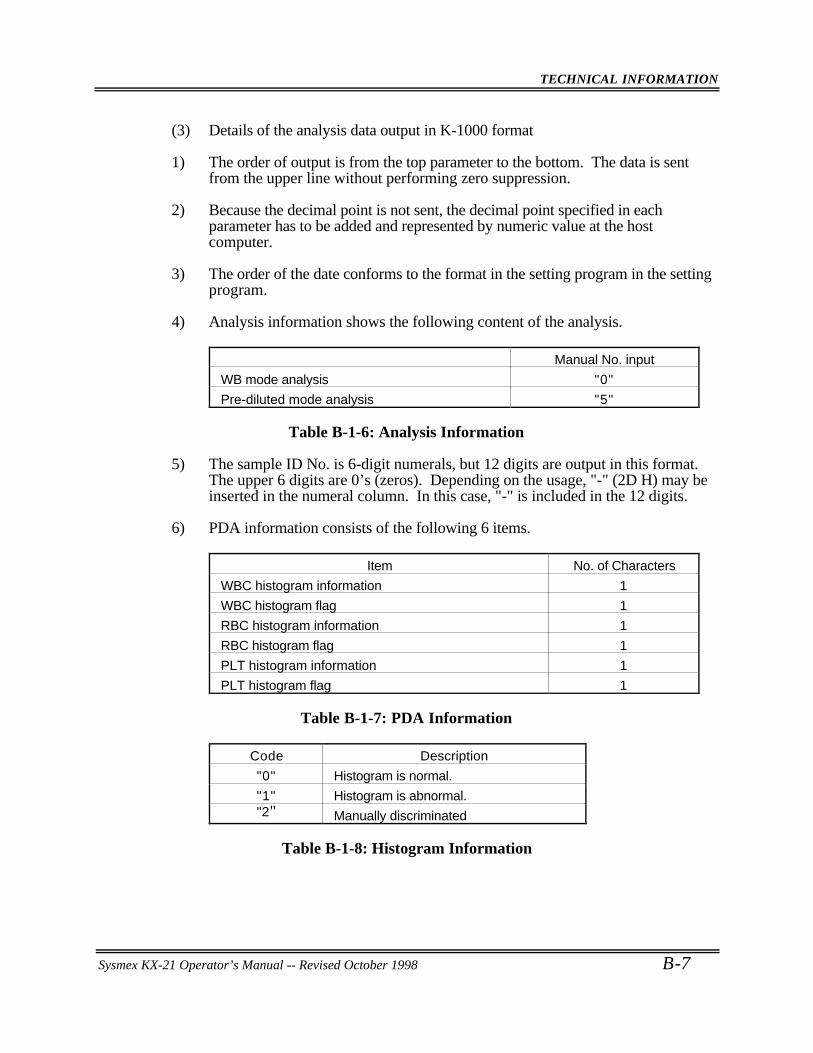
TECHNICAL INFORMATION
Sysmex KX-21 Operator’s Manual -- Revised October 1998 B-7
(3) Details of the analysis data output in K-1000 format
1) The order of output is from the top parameter to the bottom. The data is sentfrom the upper line without performing zero suppression.
2) Because the decimal point is not sent, the decimal point specified in eachparameter has to be added and represented by numeric value at the hostcomputer.
3) The order of the date conforms to the format in the setting program in the settingprogram.
4) Analysis information shows the following content of the analysis.
Manual No. input
WB mode analysis "0"
Pre-diluted mode analysis "5"
Table B-1-6: Analysis Information
5) The sample ID No. is 6-digit numerals, but 12 digits are output in this format.The upper 6 digits are 0’s (zeros). Depending on the usage, "-" (2D H) may beinserted in the numeral column. In this case, "-" is included in the 12 digits.
6) PDA information consists of the following 6 items.
Item No. of Characters
WBC histogram information 1
WBC histogram flag 1
RBC histogram information 1
RBC histogram flag 1
PLT histogram information 1
PLT histogram flag 1
Table B-1-7: PDA Information
Code Description
"0" Histogram is normal.
"1" Histogram is abnormal."2" Manually discriminated
Table B-1-8: Histogram Information
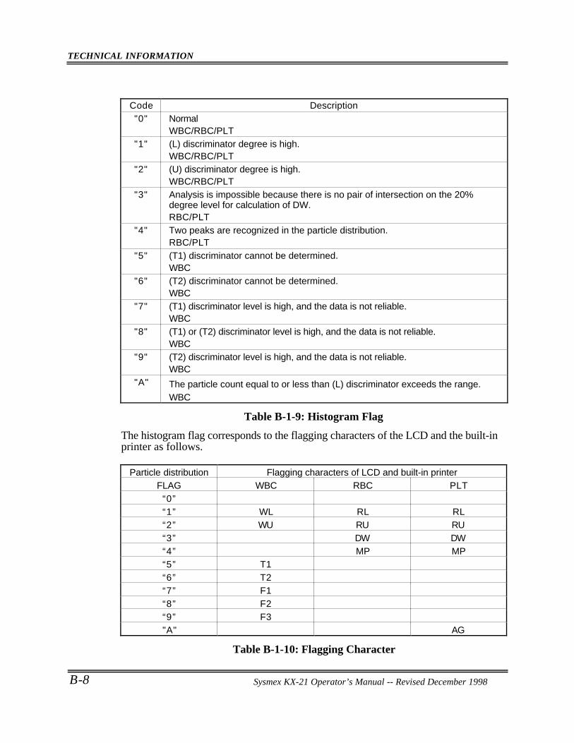
TECHNICAL INFORMATION
B-8 Sysmex KX-21 Operator’s Manual -- Revised October 1998
Code Description"0" Normal
WBC/RBC/PLT"1" (L) discriminator degree is high.
WBC/RBC/PLT"2" (U) discriminator degree is high.
WBC/RBC/PLT"3" Analysis is impossible because there is no pair of intersection on the 20%
degree level for calculation of DW.RBC/PLT
"4" Two peaks are recognized in the particle distribution.RBC/PLT
"5" (T1) discriminator cannot be determined.WBC
"6" (T2) discriminator cannot be determined.WBC
"7" (T1) discriminator level is high, and the data is not reliable.WBC
"8" (T1) or (T2) discriminator level is high, and the data is not reliable.WBC
"9" (T2) discriminator level is high, and the data is not reliable.WBC
"A" The particle count equal to or less than (L) discriminator exceeds the range.WBC
Table B-1-9: Histogram Flag
The histogram flag corresponds to the flagging characters of the LCD and the built-inprinter as follows.
Particle distribution Flagging characters of LCD and built-in printerFLAG WBC RBC PLT
“0”“1” WL RL RL“2” WU RU RU“3” DW DW“4” MP MP“5” T1“6” T2“7” F1“8” F2“9” F3"A" AG
Table B-1-10: Flagging Character
Sysmex KX-21 Operator’s Manual -- Revised December 1998
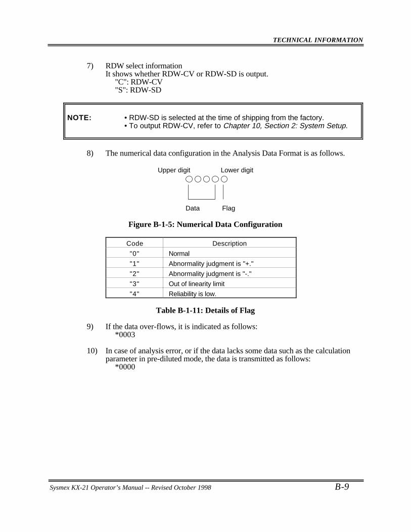
TECHNICAL INFORMATION
Sysmex KX-21 Operator’s Manual -- Revised October 1998 B-9
7) RDW select informationIt shows whether RDW-CV or RDW-SD is output.
"C": RDW-CV"S": RDW-SD
NOTE: • RDW-SD is selected at the time of shipping from the factory.• To output RDW-CV, refer to Chapter 10, Section 2: System Setup.
8) The numerical data configuration in the Analysis Data Format is as follows.
Upper digit Lower digit
Data Flag
Figure B-1-5: Numerical Data Configuration
Code Description
"0" Normal
"1" Abnormality judgment is "+."
"2" Abnormality judgment is "-."
"3" Out of linearity limit
"4" Reliability is low.
Table B-1-11: Details of Flag
9) If the data over-flows, it is indicated as follows:*0003
10) In case of analysis error, or if the data lacks some data such as the calculationparameter in pre-diluted mode, the data is transmitted as follows:
*0000
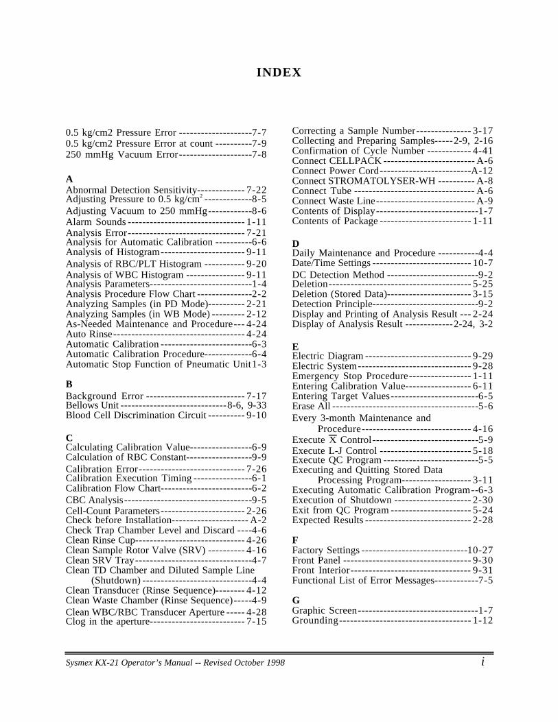
Sysmex KX-21 Operator’s Manual -- Revised October 1998 i
INDEX
0.5 kg/cm2 Pressure Error --------------------7-70.5 kg/cm2 Pressure Error at count ----------7-9250 mmHg Vacuum Error--------------------7-8
AAbnormal Detection Sensitivity------------- 7-22Adjusting Pressure to 0.5 kg/cm2 -------------8-5Adjusting Vacuum to 250 mmHg------------8-6Alarm Sounds -------------------------------- 1-11Analysis Error-------------------------------- 7-21Analysis for Automatic Calibration ----------6-6Analysis of Histogram----------------------- 9-11Analysis of RBC/PLT Histogram ----------- 9-20Analysis of WBC Histogram ---------------- 9-11Analysis Parameters----------------------------1-4Analysis Procedure Flow Chart ---------------2-2Analyzing Samples (in PD Mode)---------- 2-21Analyzing Samples (in WB Mode) --------- 2-12As-Needed Maintenance and Procedure--- 4-24Auto Rinse------------------------------------ 4-24Automatic Calibration -------------------------6-3Automatic Calibration Procedure-------------6-4Automatic Stop Function of Pneumatic Unit1-3
BBackground Error --------------------------- 7-17Bellows Unit -----------------------------8-6, 9-33Blood Cell Discrimination Circuit ---------- 9-10
CCalculating Calibration Value-----------------6-9Calculation of RBC Constant------------------9-9Calibration Error----------------------------- 7-26Calibration Execution Timing ----------------6-1Calibration Flow Chart-------------------------6-2CBC Analysis-----------------------------------9-5Cell-Count Parameters----------------------- 2-26Check before Installation--------------------- A-2Check Trap Chamber Level and Discard ----4-6Clean Rinse Cup------------------------------ 4-26Clean Sample Rotor Valve (SRV) ---------- 4-16Clean SRV Tray--------------------------------4-7Clean TD Chamber and Diluted Sample Line
(Shutdown) ------------------------------4-4Clean Transducer (Rinse Sequence)-------- 4-12Clean Waste Chamber (Rinse Sequence)-----4-9Clean WBC/RBC Transducer Aperture ----- 4-28Clog in the aperture-------------------------- 7-15
Correcting a Sample Number--------------- 3-17Collecting and Preparing Samples-----2-9, 2-16Confirmation of Cycle Number ------------ 4-41Connect CELLPACK ------------------------- A-6Connect Power Cord-------------------------A-12Connect STROMATOLYSER-WH ---------- A-8Connect Tube --------------------------------- A-6Connect Waste Line--------------------------- A-9Contents of Display----------------------------1-7Contents of Package ------------------------- 1-11
DDaily Maintenance and Procedure -----------4-4Date/Time Settings --------------------------- 10-7DC Detection Method -------------------------9-2Deletion--------------------------------------- 5-25Deletion (Stored Data)----------------------- 3-15Detection Principle-----------------------------9-2Display and Printing of Analysis Result --- 2-24Display of Analysis Result -------------2-24, 3-2
EElectric Diagram ----------------------------- 9-29Electric System------------------------------- 9-28Emergency Stop Procedure----------------- 1-11Entering Calibration Value------------------ 6-11Entering Target Values------------------------6-5Erase All ----------------------------------------5-6Every 3-month Maintenance and
Procedure------------------------------ 4-16Execute X Control-----------------------------5-9Execute L-J Control ------------------------- 5-18Execute QC Program --------------------------5-5Executing and Quitting Stored Data
Processing Program------------------- 3-11Executing Automatic Calibration Program--6-3Execution of Shutdown --------------------- 2-30Exit from QC Program ---------------------- 5-24Expected Results ----------------------------- 2-28
FFactory Settings -----------------------------10-27Front Panel ----------------------------------- 9-30Front Interior--------------------------------- 9-31Functional List of Error Messages------------7-5
GGraphic Screen---------------------------------1-7Grounding------------------------------------ 1-12
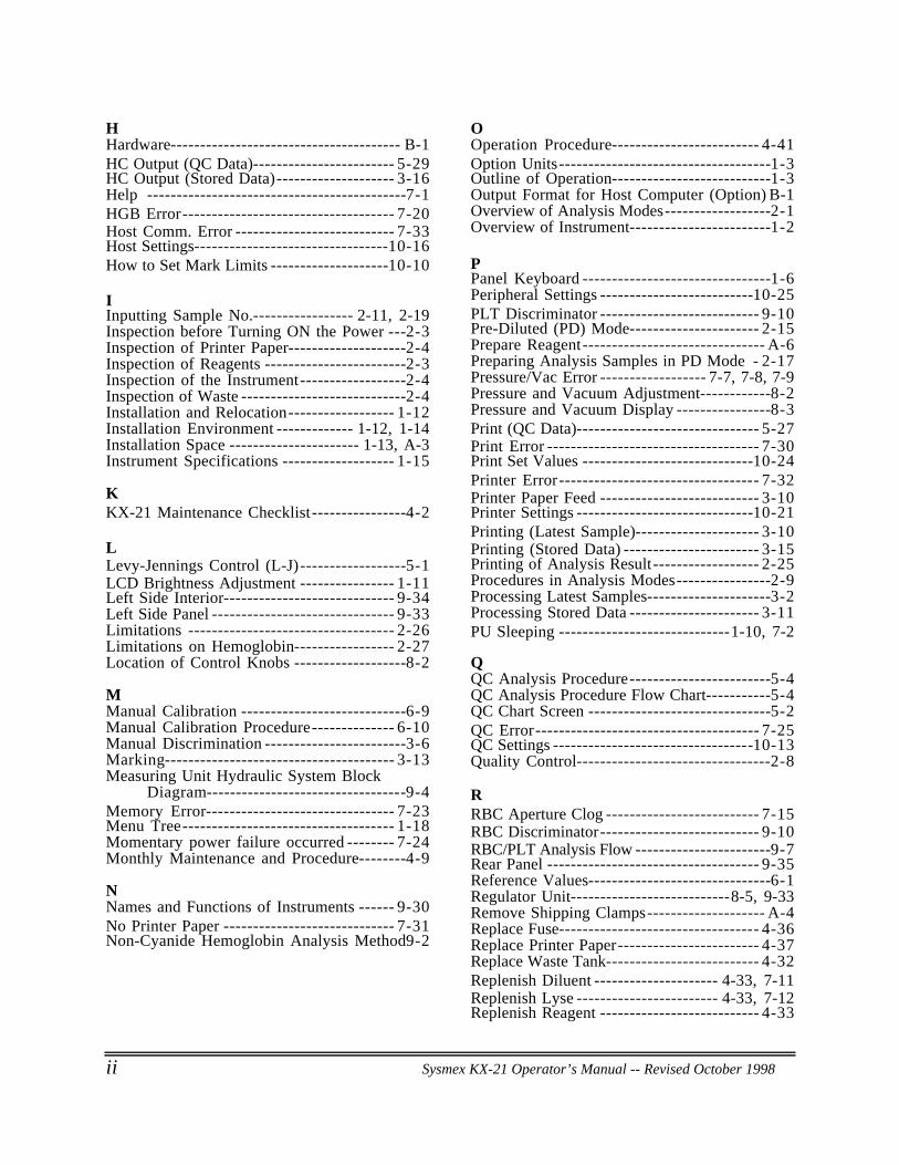
ii Sysmex KX-21 Operator’s Manual -- Revised October 1998
HHardware--------------------------------------- B-1HC Output (QC Data)------------------------ 5-29HC Output (Stored Data)-------------------- 3-16Help --------------------------------------------7-1HGB Error------------------------------------ 7-20Host Comm. Error --------------------------- 7-33Host Settings---------------------------------10-16How to Set Mark Limits --------------------10-10
IInputting Sample No.----------------- 2-11, 2-19Inspection before Turning ON the Power ---2-3Inspection of Printer Paper--------------------2-4Inspection of Reagents ------------------------2-3Inspection of the Instrument------------------2-4Inspection of Waste ----------------------------2-4Installation and Relocation------------------ 1-12Installation Environment ------------- 1-12, 1-14Installation Space ---------------------- 1-13, A-3Instrument Specifications ------------------- 1-15
KKX-21 Maintenance Checklist----------------4-2
LLevy-Jennings Control (L-J)------------------5-1LCD Brightness Adjustment ---------------- 1-11Left Side Interior----------------------------- 9-34Left Side Panel ------------------------------- 9-33Limitations ----------------------------------- 2-26Limitations on Hemoglobin----------------- 2-27Location of Control Knobs -------------------8-2
MManual Calibration ----------------------------6-9Manual Calibration Procedure-------------- 6-10Manual Discrimination ------------------------3-6Marking--------------------------------------- 3-13Measuring Unit Hydraulic System Block
Diagram----------------------------------9-4Memory Error-------------------------------- 7-23Menu Tree------------------------------------ 1-18Momentary power failure occurred -------- 7-24Monthly Maintenance and Procedure--------4-9
NNames and Functions of Instruments ------ 9-30No Printer Paper ----------------------------- 7-31Non-Cyanide Hemoglobin Analysis Method9-2
OOperation Procedure------------------------- 4-41Option Units------------------------------------1-3Outline of Operation---------------------------1-3Output Format for Host Computer (Option) B-1Overview of Analysis Modes------------------2-1Overview of Instrument------------------------1-2
PPanel Keyboard --------------------------------1-6Peripheral Settings --------------------------10-25PLT Discriminator --------------------------- 9-10Pre-Diluted (PD) Mode---------------------- 2-15Prepare Reagent------------------------------- A-6Preparing Analysis Samples in PD Mode - 2-17Pressure/Vac Error ------------------ 7-7, 7-8, 7-9Pressure and Vacuum Adjustment------------8-2Pressure and Vacuum Display ----------------8-3Print (QC Data)------------------------------- 5-27Print Error ------------------------------------ 7-30Print Set Values -----------------------------10-24Printer Error---------------------------------- 7-32Printer Paper Feed --------------------------- 3-10Printer Settings ------------------------------10-21Printing (Latest Sample)--------------------- 3-10Printing (Stored Data) ----------------------- 3-15Printing of Analysis Result------------------ 2-25Procedures in Analysis Modes----------------2-9Processing Latest Samples---------------------3-2Processing Stored Data ---------------------- 3-11PU Sleeping -----------------------------1-10, 7-2
QQC Analysis Procedure------------------------5-4QC Analysis Procedure Flow Chart-----------5-4QC Chart Screen -------------------------------5-2QC Error-------------------------------------- 7-25QC Settings ----------------------------------10-13Quality Control---------------------------------2-8
RRBC Aperture Clog -------------------------- 7-15RBC Discriminator--------------------------- 9-10RBC/PLT Analysis Flow -----------------------9-7Rear Panel ------------------------------------ 9-35Reference Values-------------------------------6-1Regulator Unit---------------------------8-5, 9-33Remove Shipping Clamps-------------------- A-4Replace Fuse---------------------------------- 4-36Replace Printer Paper------------------------ 4-37Replace Waste Tank-------------------------- 4-32Replenish Diluent --------------------- 4-33, 7-11Replenish Lyse ------------------------ 4-33, 7-12Replenish Reagent --------------------------- 4-33
Sysmex KX-21 Operator’s Manual -- Revised October 1998 iii
Reset Sampling Valve (SRV)Cycle Counter ------------------------- 4-22
Right Side Panel------------------------------ 9-32Rinse Motor Error -------------------- 7-13, 7-14Room Temp. High--------------------------- 7-16Room Temp. Low---------------------------- 7-16
SSampling Error------------------------ 7-18, 7-19Select QC File ----------------------------------5-5Selecting Automatic Calibration Parameter--6-4Selecting Pre-Diluted Mode----------------- 2-18Selecting Whole Blood Mode--------------- 2-10Set Printer Paper -----------------------------A-10Set TARGET/LIMIT Values ------------------5-7Set Value Error------------------------------- 7-23Shutdown Procedure------------------------- 2-30Software---------------------------------------- B-3Start-up Procedure-----------------------------2-3Status Display -------------------------------- 7-34Status Display Messages-----------------------1-8Stopping the Pneumatic Unit --------------- 2-29Stored Data Screen--------------------------- 3-12Supplies List---------------------------------- 4-40Supplies Replacement ----------------------- 4-33System Setup --------------------------------- 10-2
TTroubleshooting Guide------------------------7-7Troubleshooting Guide
(Analysis Errors)---------------------- 7-17Troubleshooting Guide
(Built-in Printer Errors) -------------- 7-30Troubleshooting Guide
(Chamber Errors) --------------------- 7-10Troubleshooting Guide
(External Device Errors) ------------- 7-33Troubleshooting Guide
(Maintenance Errors) -------------- 7-27Troubleshooting Guide (Memory Errors)- 7-23Troubleshooting Guide (Motor Errors)---- 7-13Troubleshooting Guide (Others) ----------- 7-25Troubleshooting Guide
(Pressure/Vacuum Errors)--------------7-7Troubleshooting Guide
(Temperature Errors)----------------- 7-16Troubleshooting Guide
(Transducer Errors)------------------- 7-15Turn Power On-------------------------------A-12Turning ON the Power and Self-Check------2-5
UUpdating Calibration Value
(Manual Calibration) ----------------- 6-12Updating Calibration Value
(Automatic Calibration) ----------------6-8
WWaste Not Draining -------------------------- 7-10WBC Aperture Clog-------------------------- 7-15WBC Discriminator -------------------------- 9-10WBC/HGB Analysis Error ------------------- 7-21WBC/HGB Analysis Flow----------------------9-5Weekly Maintenance and Procedure ---------4-7When You Suspect A Trouble ----------------7-2Whole Blood (WB) Mode ---------------------2-9
XX Control---------------------------------------5-1