symmetrical fault current calculationseebag/short-circuit current calculations.pdf · introduction...
TRANSCRIPT
Symmetrical Fault Current Calculations
ECG 740
Introduction
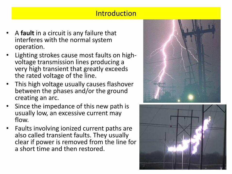
• A fault in a circuit is any failure that interferes with the normal system operation.
• Lighting strokes cause most faults on high-voltage transmission lines producing a very high transient that greatly exceeds the rated voltage of the line.
• This high voltage usually causes flashover between the phases and/or the ground creating an arc.
• Since the impedance of this new path is usually low, an excessive current may flow.
• Faults involving ionized current paths are also called transient faults. They usually clear if power is removed from the line for a short time and then restored.
Introduction
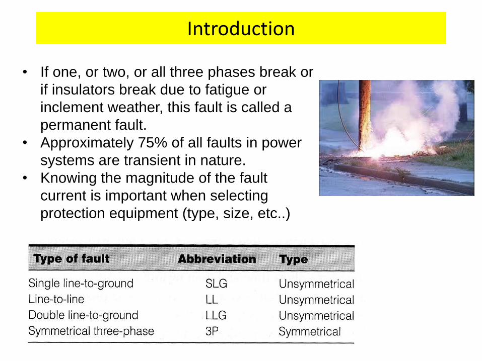
• If one, or two, or all three phases break or
if insulators break due to fatigue or
inclement weather, this fault is called a
permanent fault.
• Approximately 75% of all faults in power
systems are transient in nature.
• Knowing the magnitude of the fault
current is important when selecting
protection equipment (type, size, etc..)
3-Phase fault current transients in synchronous generators
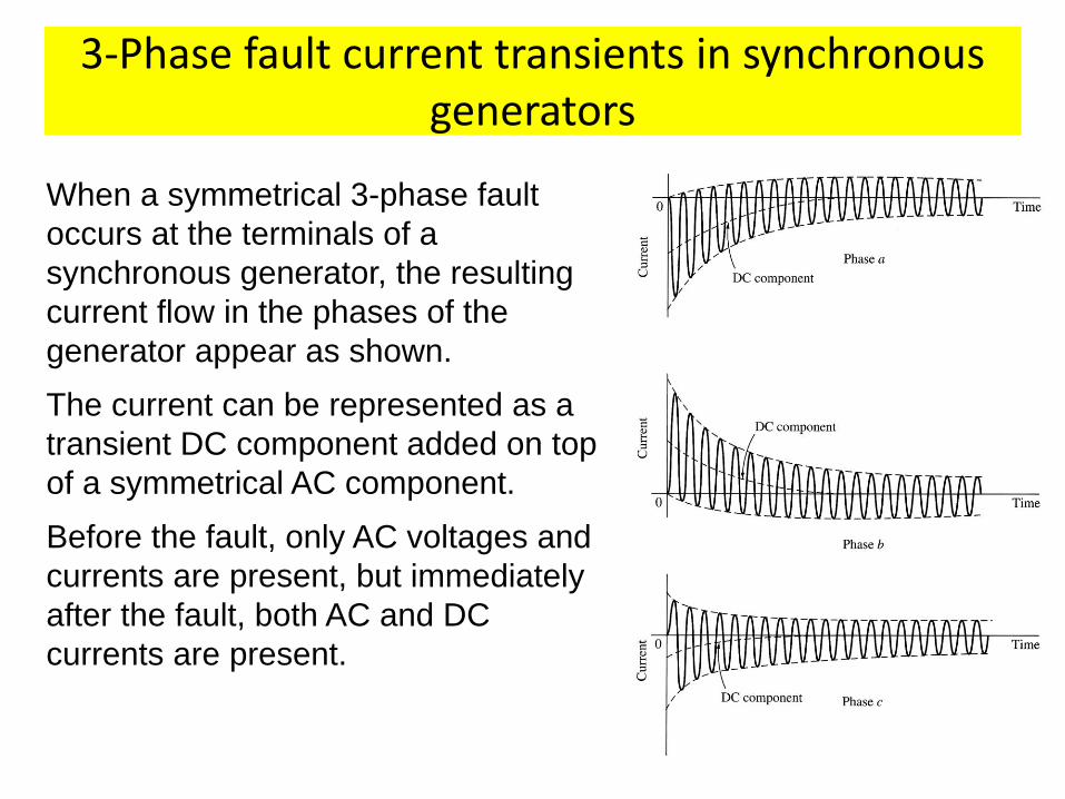
When a symmetrical 3-phase fault
occurs at the terminals of a
synchronous generator, the resulting
current flow in the phases of the
generator appear as shown.
The current can be represented as a
transient DC component added on top
of a symmetrical AC component.
Before the fault, only AC voltages and
currents are present, but immediately
after the fault, both AC and DC
currents are present.
Fault current transients in machines • When the fault occurs, the AC component of current jumps to
a very large value, but the total current cannot change
instantly since the series inductance of the machine will
prevent this from happening.
• The transient DC component of current is just large enough
such that the sum of the AC and DC components just after
the fault equals the AC current just before the fault.
• Since the instantaneous values of current at the moment of
the fault are different in each phase, the magnitude of DC
components will be different in different phases.
• These DC components decay fairly quickly, but they initially
average about 50 - 60% of the AC current flow the instant
after the fault occurs. The total initial current is therefore
typically 1.5 or 1.6 times the AC component alone.
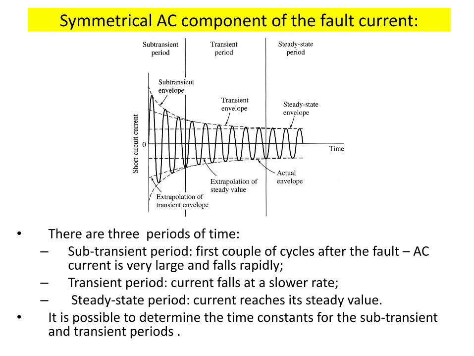
Symmetrical AC component of the fault current:
• There are three periods of time: – Sub-transient period: first couple of cycles after the fault – AC
current is very large and falls rapidly; – Transient period: current falls at a slower rate; – Steady-state period: current reaches its steady value.
• It is possible to determine the time constants for the sub-transient and transient periods .
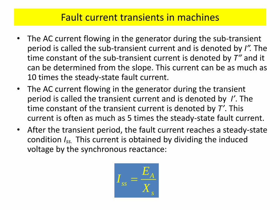
Fault current transients in machines
• The AC current flowing in the generator during the sub-transient period is called the sub-transient current and is denoted by I”. The time constant of the sub-transient current is denoted by T” and it can be determined from the slope. This current can be as much as 10 times the steady-state fault current.
• The AC current flowing in the generator during the transient period is called the transient current and is denoted by I’. The time constant of the transient current is denoted by T’. This current is often as much as 5 times the steady-state fault current.
• After the transient period, the fault current reaches a steady-state condition Iss. This current is obtained by dividing the induced voltage by the synchronous reactance:
Ass
s
EI
X
Fault current transients in machines
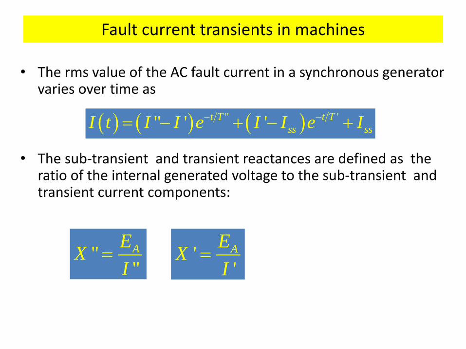
• The rms value of the AC fault current in a synchronous generator varies over time as
• The sub-transient and transient reactances are defined as the ratio of the internal generated voltage to the sub-transient and transient current components:
""
AEX
I
" '" ' 't T t T
ss ssI t I I e I I e I
''
AEX
I
Fault current calculations
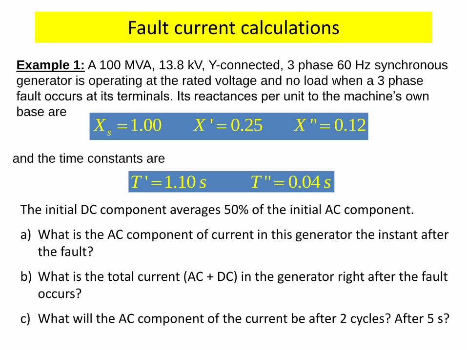
Example 1: A 100 MVA, 13.8 kV, Y-connected, 3 phase 60 Hz synchronous
generator is operating at the rated voltage and no load when a 3 phase
fault occurs at its terminals. Its reactances per unit to the machine’s own
base are 1.00 ' 0.25 " 0.12sX X X
and the time constants are
' 1.10 " 0.04T s T s
The initial DC component averages 50% of the initial AC component.
a) What is the AC component of current in this generator the instant after the fault?
b) What is the total current (AC + DC) in the generator right after the fault occurs?
c) What will the AC component of the current be after 2 cycles? After 5 s?
Fault current calculations
The base current of the generator can be computed as
,
,
100,000,0004,184
3 3 13,800
baseL base
L base
SI A
V
The subtransient, transient, and steady-state currents are (per-unit and
Amps) 1.0
" 8.333 34,900" 0.12
1.0' 4 ,700
' 0.25
1.01 4,184
1.0
A
A
Ass
s
EI pu A
X
EI pu A
X
EI pu A
X
Fault current calculations
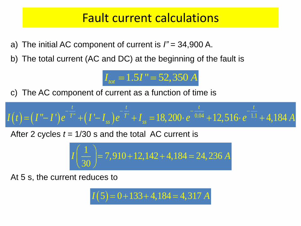
a) The initial AC component of current is I” = 34,900 A.
b) The total current (AC and DC) at the beginning of the fault is
1.5 " 52,350totI I A
c) The AC component of current as a function of time is
0.04 1.1" '" ' ' 18,200 12,516 4,184t tt t
T Tss ssI t I I e I I e I e e A
After 2 cycles t = 1/30 s and the total AC current is
17,910 12,142 4,184 24,236
30I A
At 5 s, the current reduces to
5 0 133 4,184 4,317I A
Fault current transients
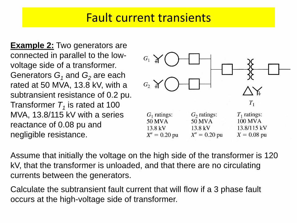
Example 2: Two generators are
connected in parallel to the low-
voltage side of a transformer.
Generators G1 and G2 are each
rated at 50 MVA, 13.8 kV, with a
subtransient resistance of 0.2 pu.
Transformer T1 is rated at 100
MVA, 13.8/115 kV with a series
reactance of 0.08 pu and
negligible resistance.
Assume that initially the voltage on the high side of the transformer is 120
kV, that the transformer is unloaded, and that there are no circulating
currents between the generators.
Calculate the subtransient fault current that will flow if a 3 phase fault
occurs at the high-voltage side of transformer.
Fault current calculations
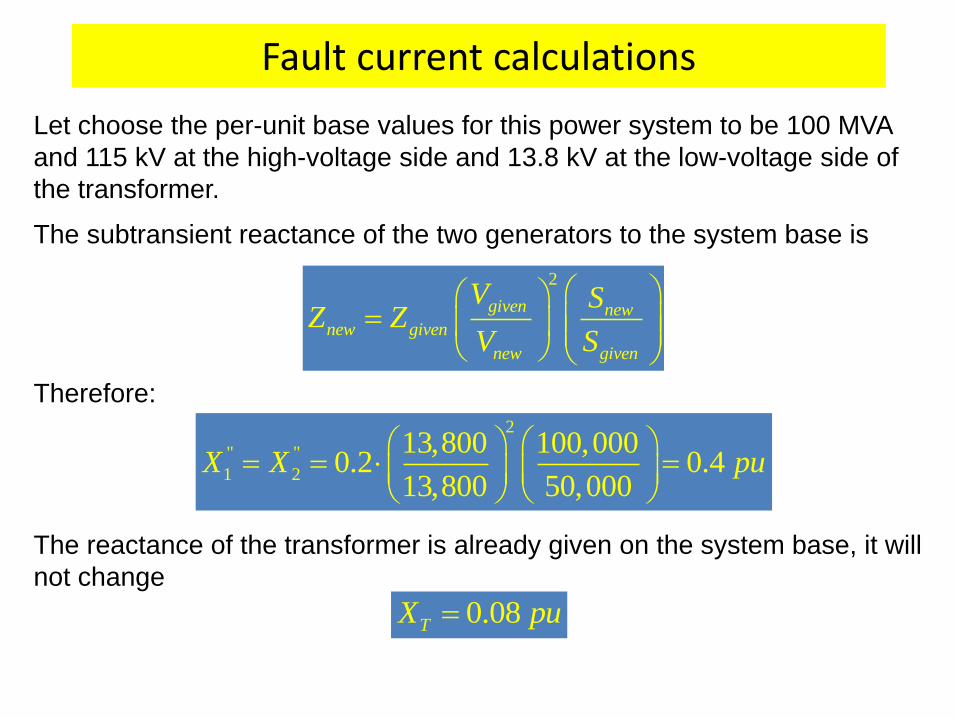
Let choose the per-unit base values for this power system to be 100 MVA
and 115 kV at the high-voltage side and 13.8 kV at the low-voltage side of
the transformer.
The subtransient reactance of the two generators to the system base is
2
given newnew given
new given
V SZ Z
V S
The reactance of the transformer is already given on the system base, it will
not change
2
" "
1 2
13,800 100,0000.2 0.4
13,800 50,000X X pu
0.08TX pu
Therefore:
Symmetrical fault current calculations
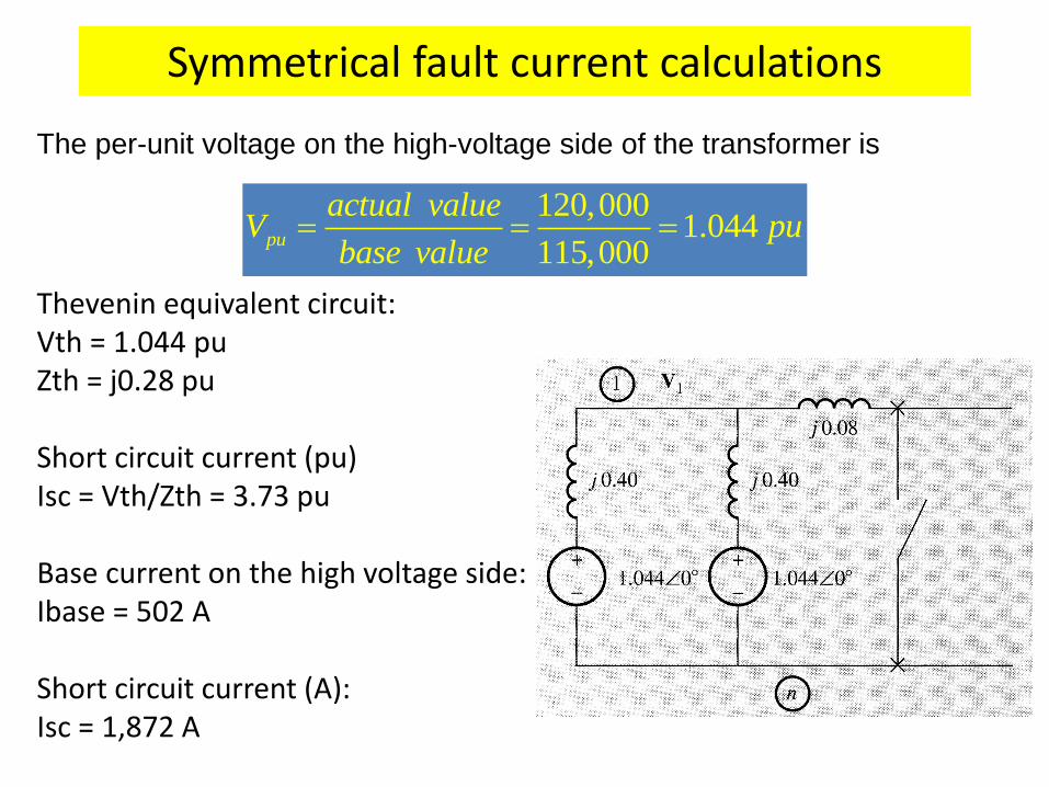
The per-unit voltage on the high-voltage side of the transformer is
120,0001.044
115,000pu
actual valueV pu
base value
Thevenin equivalent circuit: Vth = 1.044 pu Zth = j0.28 pu Short circuit current (pu) Isc = Vth/Zth = 3.73 pu Base current on the high voltage side: Ibase = 502 A Short circuit current (A): Isc = 1,872 A
Symmetrical fault current calculations
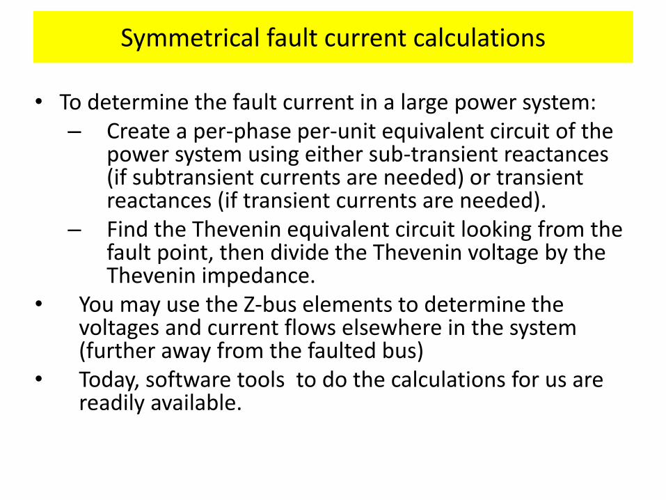
• To determine the fault current in a large power system: – Create a per-phase per-unit equivalent circuit of the
power system using either sub-transient reactances (if subtransient currents are needed) or transient reactances (if transient currents are needed).
– Find the Thevenin equivalent circuit looking from the fault point, then divide the Thevenin voltage by the Thevenin impedance.
• You may use the Z-bus elements to determine the voltages and current flows elsewhere in the system (further away from the faulted bus)
• Today, software tools to do the calculations for us are readily available.
Fault current calculations using the impedance matrix
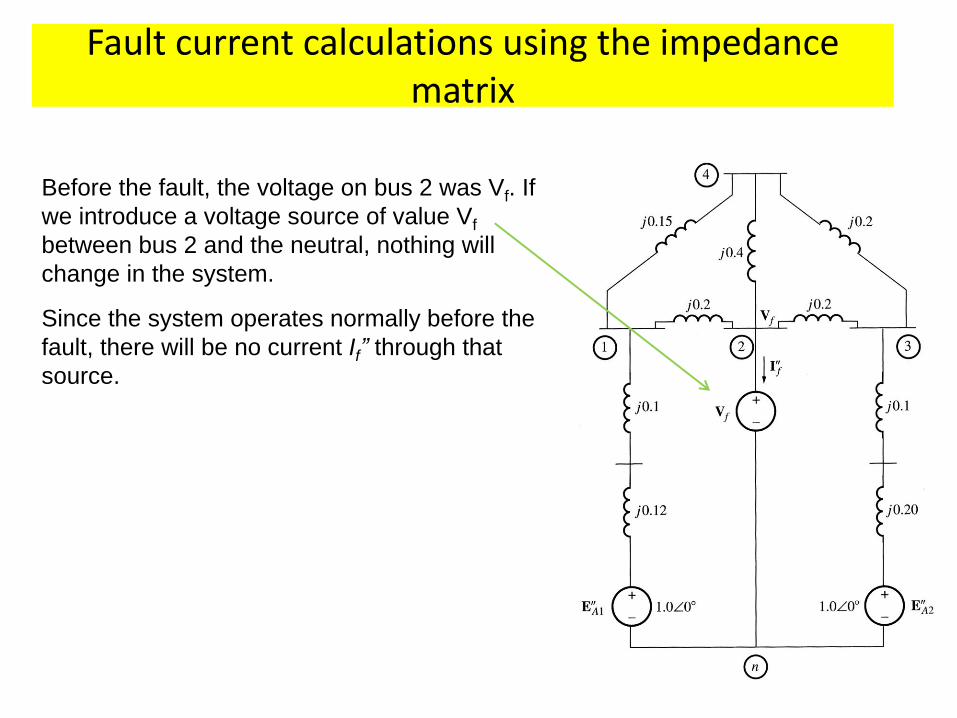
Before the fault, the voltage on bus 2 was Vf. If
we introduce a voltage source of value Vf
between bus 2 and the neutral, nothing will
change in the system.
Since the system operates normally before the
fault, there will be no current If” through that
source.
Fault current calculations using the impedance matrix
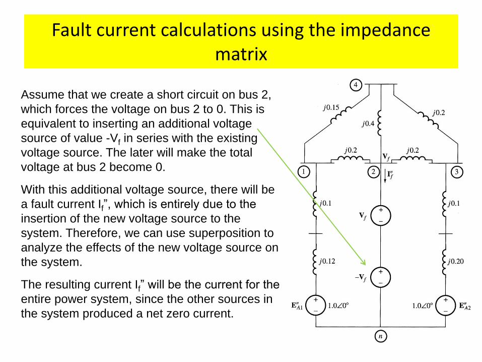
Assume that we create a short circuit on bus 2,
which forces the voltage on bus 2 to 0. This is
equivalent to inserting an additional voltage
source of value -Vf in series with the existing
voltage source. The later will make the total
voltage at bus 2 become 0.
With this additional voltage source, there will be
a fault current If”, which is entirely due to the
insertion of the new voltage source to the
system. Therefore, we can use superposition to
analyze the effects of the new voltage source on
the system.
The resulting current If” will be the current for the
entire power system, since the other sources in
the system produced a net zero current.
Fault current calculations using the impedance matrix
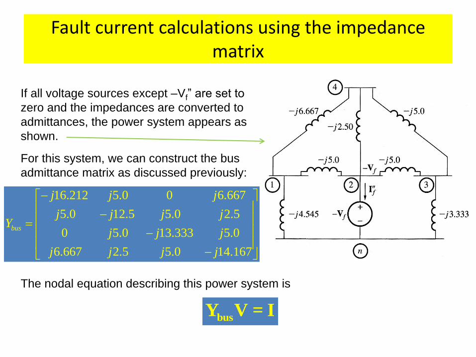
If all voltage sources except –Vf” are set to
zero and the impedances are converted to
admittances, the power system appears as
shown.
For this system, we can construct the bus
admittance matrix as discussed previously:
16.212 5.0 0 6.667
5.0 12.5 5.0 2.5
0 5.0 13.333 5.0
6.667 2.5 5.0 14.167
bus
j j j
j j j jY
j j j
j j j j
The nodal equation describing this power system is
busY V = I
Fault current calculations using the impedance matrix
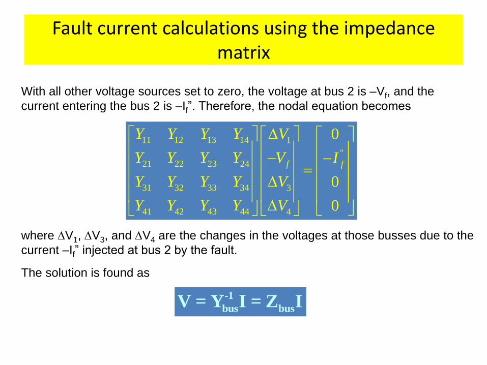
With all other voltage sources set to zero, the voltage at bus 2 is –Vf, and the
current entering the bus 2 is –If”. Therefore, the nodal equation becomes
11 12 13 14 1
"
21 22 23 24
31 32 33 34 3
41 42 43 44 4
0
0
0
f f
Y Y Y Y V
Y Y Y Y V I
Y Y Y Y V
Y Y Y Y V
where V1, V3, and V4 are the changes in the voltages at those busses due to the
current –If” injected at bus 2 by the fault.
The solution is found as
-1
bus busV = Y I = Z I
Fault current calculations using the impedance matrix
11 12 13 141
"
21 22 23 24
31 32 33 343
41 42 43 444
0
0
0
f f
Z Z Z ZV
Z Z Z ZV I
Z Z Z ZV
Z Z Z ZV
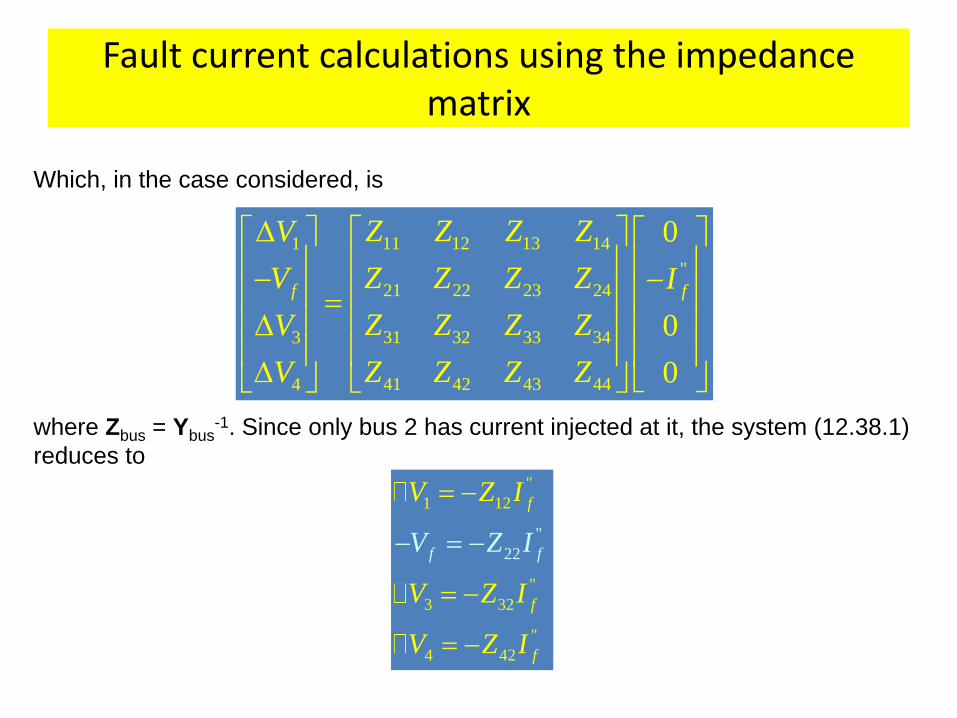
Which, in the case considered, is
where Zbus = Ybus-1. Since only bus 2 has current injected at it, the system (12.38.1)
reduces to
"
"
1 12
"
3 32
"
2
4
2
42
f
f
f
f f
V Z I
V Z I
V
I
Z I
V Z
Fault current calculations using the impedance matrix
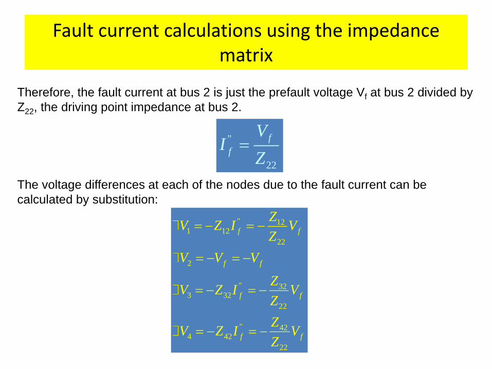
Therefore, the fault current at bus 2 is just the prefault voltage Vf at bus 2 divided by
Z22, the driving point impedance at bus 2.
"
22
f
f
VI
Z
The voltage differences at each of the nodes due to the fault current can be
calculated by substitution:
" 121 12
22
2
" 323 32
22
" 424 42
22
f f
f f
f f
f f
ZV Z I V
Z
V V V
ZV Z I V
Z
ZV Z I V
Z
Fault current calculations using the impedance matrix
Assuming that the power system was running at no load conditions before the fault,
it is easy to calculate the voltages at every bus during the fault. At no load, the
voltage will be the same on every bus in the power system, so the voltage on every
bus in the system is Vf. The change in voltage on every bus caused by the fault
current –If” - so the total voltage during the fault is
12
22
12
22
1
2
32
3
22
4
1
2
32
3
22
4
4 42
22
2
22
1
0
1
1
f
f f
ff f
ff f
f f
f
f
ZV
ZV VV
VV VV
ZVV VV
ZV
Z
ZV
VVZ
VZ
VZ
Z
VVZ
VZ
The current through a line between bus i and bus j is found by
ij ij i jI Y V V
Fault current calculations using the impedance matrix
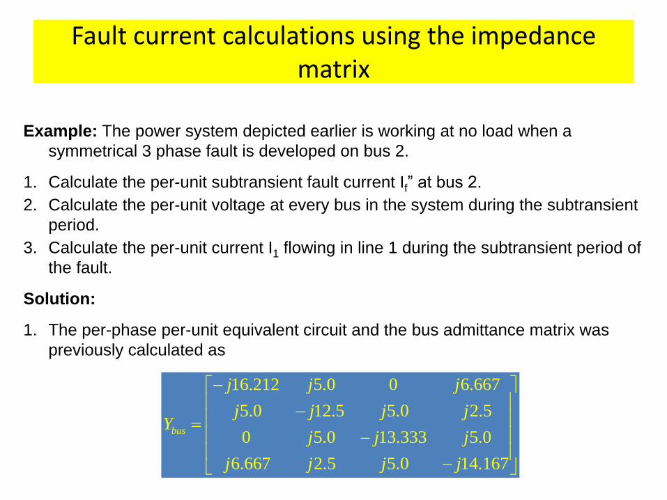
Example: The power system depicted earlier is working at no load when a
symmetrical 3 phase fault is developed on bus 2.
1. Calculate the per-unit subtransient fault current If” at bus 2.
2. Calculate the per-unit voltage at every bus in the system during the subtransient
period.
3. Calculate the per-unit current I1 flowing in line 1 during the subtransient period of
the fault.
Solution:
1. The per-phase per-unit equivalent circuit and the bus admittance matrix was
previously calculated as
16.212 5.0 0 6.667
5.0 12.5 5.0 2.5
0 5.0 13.333 5.0
6.667 2.5 5.0 14.167
bus
j j j
j j j jY
j j j
j j j j
Fault current calculations using the impedance matrix
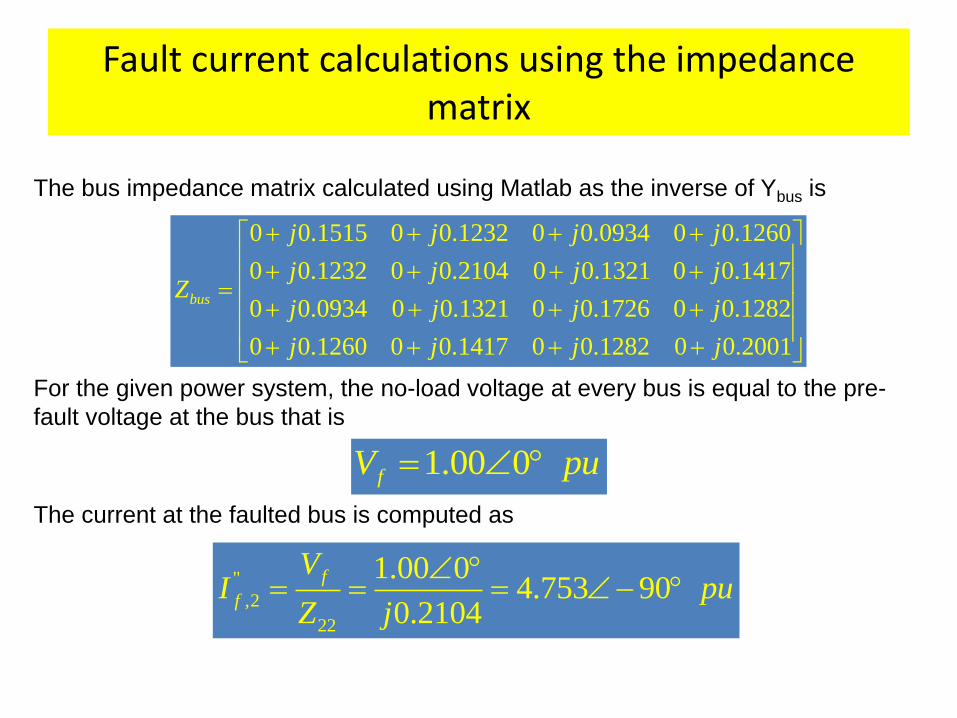
The bus impedance matrix calculated using Matlab as the inverse of Ybus is
0 0.1515 0 0.1232 0 0.0934 0 0.1260
0 0.1232 0 0.2104 0 0.1321 0 0.1417
0 0.0934 0 0.1321 0 0.1726 0 0.1282
0 0.1260 0 0.1417 0 0.1282 0 0.2001
bus
j j j j
j j j jZ
j j j j
j j j j
For the given power system, the no-load voltage at every bus is equal to the pre-
fault voltage at the bus that is
1.00 0fV pu
The current at the faulted bus is computed as
"
,2
22
1.00 04.753 90
0.2104
f
f
VI pu
Z j
Fault current calculations using the impedance matrix
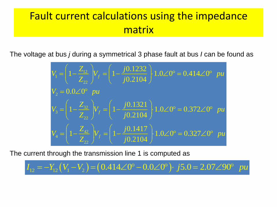
The voltage at bus j during a symmetrical 3 phase fault at bus I can be found as
121
22
2
323
22
424
22
0.12321 1 1.0 0 0.414 0
0.2104
0.0 0
0.13211 1 1.0 0 0.372 0
0.2104
0.14171 1 1.0 0 0.327 0
0.2104
f
f
f
Z jV V pu
Z j
V pu
Z jV V pu
Z j
Z jV V pu
Z j
The current through the transmission line 1 is computed as
12 12 1 2 0.414 0 0.0 0 5.0 2.07 90I Y V V j pu
That’s it!