swing door opener model: dm-50 / dm-100 - …cache.smarthome.com/manuals/73105m.pdfswing door opener...
TRANSCRIPT
US Patent 6243000B1Patent Pending
Swing Door Opener
MODEL: DM-50 / DM-100
P/N. 101A393 DEC, 2005
Swing Door Opener
USER'S INSTRUCTIONS
En
glis
h

CONTENTIntroduction.......................................................................................................................................................................................4
Overview.....................................................................................................................................................................................4Installation - In Swing.......................................................................................................................................................................7
Determine the door configuration..........................................................................................................................................8Installing the Door Opener......................................................................................................................................................9In-Swing Left and In-Swing Right...........................................................................................................................................9
Disable the existing door lock.......................................................................................................................................9Mounting the Slider Bracket...........................................................................................................................................9Installing the operator assembly onto the mounting plate....................................................................................10Selecting the door type.................................................................................................................................................11Mounting the operator assembly with mounting plate onto the door..................................................................11Attach the door arm assenbly on the operator.........................................................................................................13Program the OPEN and CLOSE travel limits...........................................................................................................14Mounting the electromagnetic lock.............................................................................................................................14
Out-Swing Left and Out-Swing Right....................................................................................................................................17Disable the existing latch bolt.....................................................................................................................................17Mounting the Slider Bracket.........................................................................................................................................17Installing the operator assembly onto the mounting plate....................................................................................18Selecting the door type.................................................................................................................................................19Mounting the operator assembly with mounting plate onto the door .................................................................19Attach the door arm assenbly on the operator.........................................................................................................21Program the OPEN and CLOSE travel limits...........................................................................................................22Mounting the electromagnetic lock.............................................................................................................................22
Operation.................................................................................................................................................................................26Remote Control Operation...........................................................................................................................................26Mute.................................................................................................................................................................................27Obstacle detection.........................................................................................................................................................27Test the obstacle detection system..............................................................................................................................27Power failure..................................................................................................................................................................27Advanced programming / operations........................................................................................................................28Learn additional remote controls...............................................................................................................................28Erase remote controls..................................................................................................................................................28Operating Modes.............................................................................................................................................................28Toggle Modes.................................................................................................................................................................29Open / Close Mode........................................................................................................................................................29Timer Mode.....................................................................................................................................................................30Trouble Beeping...........................................................................................................................................................30Electromagnetic Lock (Optional - sold separately).................................................................................................31Closing force..................................................................................................................................................................32External Wired Push Button (sold separately).........................................................................................................32
Door opener connections/settings......................................................................................................................................33Accessories............................................................................................................................................................................34Warranty...................................................................................................................................................................................35Registration Form...................................................................................................................................................................36
–2–

–3–
***********************************************************************************************
IMPORTANT SAFETY INSTRUCTIONS
WARNING – To reduce the risk of severe injury or death:
1. READ AND FOLLOW ALL INSTRUCTIONS.2. Never let children operate or play with door controls. Keep the remote control away from
children.3. Always keep the moving door in sight and away from people and objects until it is com-
pletely closed. NO ONE SHOULD CROSS THE PATH OF THE MOVING DOOR.4. SAVE THESE INSTRUCTIONS.
***********************************************************************************************IMPORTANT INSTALLATION INSTRUCTIONS
WARNING – To reduce the risk of severe injury or death:
1. READ AND FOLLOW ALL INSTALLATION INSTRUCTIONS.2. Do not connect the opener to source of power until instructed to do so.
***********************************************************************************************PRECAUTIONS
1. This product is intended for indoor use only. The door is a solid wood or hollow-corewood or metal door.
2. This product is designed to operate the single door of right hand or left hand in-swingdoors with the measuring of 30” to 36” wide multiply 72” height and weighting less than90 lbs.
3. If the power to the unit is lost, the door can be opened manually.
***********************************************************************************************
–36–
–4–
INTRODUCTION
Overview
Congratulations on your purchase of a Skylink Swing Door Opener. This swing door opener can automaticallyopen / close any swinging doors with a press of a remote. An electromagnetic lock can also be installed forsecurity and privacy purposes. During power failure, the door can still be opened or closed manually.
An obstacle detection feature is built-in to all swing door openers, when an obstacle is detected in the path of anopening / closing door, the door opener will stop to avoid serious injury.
The user’s instructions will guide you through the whole setup procedure as well as all the programming instruc-tions. Please read and follow all safety rules and operating instructions before first use of this product.
Safety Information
When you see this Warning symbol and word, that means severe injury can result from failureto follow instructions.
When you see this Caution symbol and word, that means the property damage or injury canresult from failure to follow instructions.
This word is used to indicate the importance of the specified procedure(s). Follow them closely orotherwise the unit may not function properly.
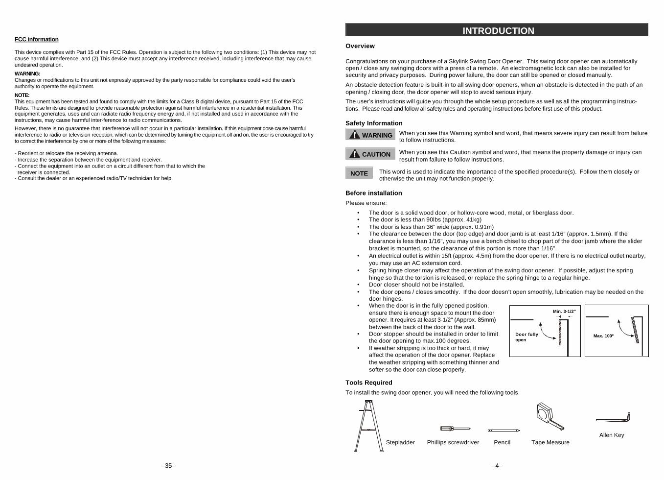
Before installation
Please ensure:
· The door is a solid wood door, or hollow-core wood, metal, or fiberglass door.· The door is less than 90lbs (approx. 41kg)· The door is less than 36” wide (approx. 0.91m)· The clearance between the door (top edge) and door jamb is at least 1/16” (approx. 1.5mm). If the
clearance is less than 1/16", you may use a bench chisel to chop part of the door jamb where the sliderbracket is mounted, so the clearance of this portion is more than 1/16".
· An electrical outlet is within 15ft (approx. 4.5m) from the door opener. If there is no electrical outlet nearby,you may use an AC extension cord.
· Spring hinge closer may affect the operation of the swing door opener. If possible, adjust the springhinge so that the torsion is released, or replace the spring hinge to a regular hinge.
· Door closer should not be installed.· The door opens / closes smoothly. If the door doesn’t open smoothly, lubrication may be needed on the
door hinges.· When the door is in the fully opened position,
ensure there is enough space to mount the dooropener. It requires at least 3-1/2" (Approx. 85mm)between the back of the door to the wall.
· Door stopper should be installed in order to limitthe door opening to max.100 degrees.
· If weather stripping is too thick or hard, it mayaffect the operation of the door opener. Replacethe weather stripping with something thinner andsofter so the door can close properly.
Tools Required
To install the swing door opener, you will need the following tools.
WARNING
CAUTION
NOTE
Stepladder Phillips screwdriver Pencil Tape MeasureAllen Key
Min. 3-1/2"
Door fullyopen
Max. 100º
–35–
FCC information
This device complies with Part 15 of the FCC Rules. Operation is subject to the following two conditions: (1) This device may notcause harmful interference, and (2) This device must accept any interference received, including interference that may causeundesired operation.
WARNING:Changes or modifications to this unit not expressly approved by the party responsible for compliance could void the user’sauthority to operate the equipment.
NOTE:This equipment has been tested and found to comply with the limits for a Class B digital device, pursuant to Part 15 of the FCCRules. These limits are designed to provide reasonable protection against harmful interference in a residential installation. Thisequipment generates, uses and can radiate radio frequency energy and, if not installed and used in accordance with theinstructions, may cause harmful inter-ference to radio communications.
However, there is no guarantee that interference will not occur in a particular installation. If this equipment dose cause harmfulinterference to radio or television reception, which can be determined by turning the equipment off and on, the user is encouraged to tryto correct the interference by one or more of the following measures:
- Reorient or relocate the receiving antenna.- Increase the separation between the equipment and receiver.- Connect the equipment into an outlet on a circuit different from that to which the receiver is connected.- Consult the dealer or an experienced radio/TV technician for help.
–5–
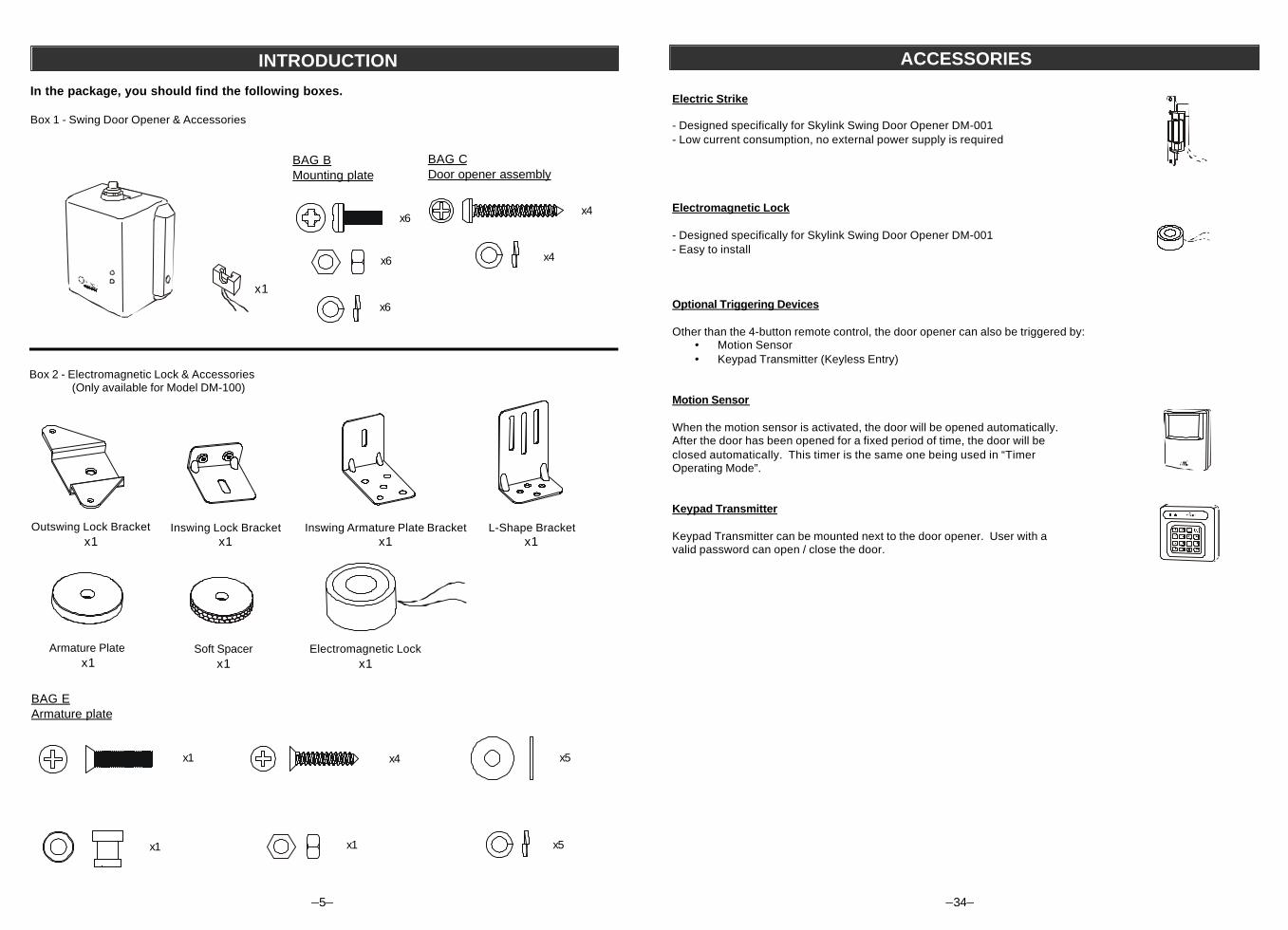
In the package, you should find the following boxes.
Box 1 - Swing Door Opener & Accessories
INTRODUCTION
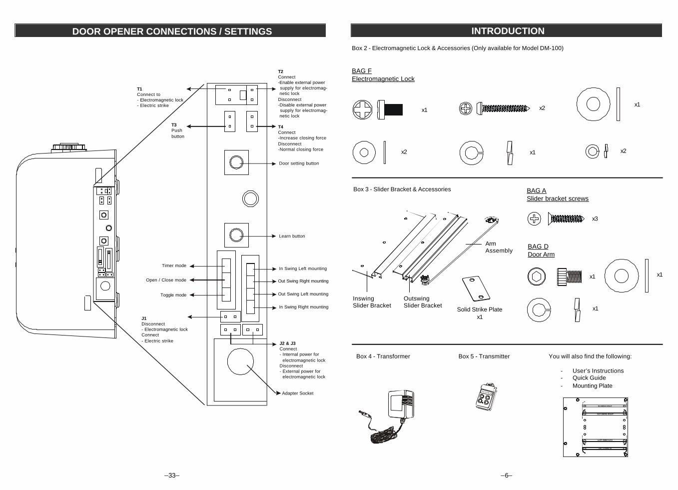
Box 2 - Electromagnetic Lock & Accessories(Only available for Model DM-100)
Armature Platex1
Electromagnetic Lockx1
Outswing Lock Bracketx1
Inswing Lock Bracketx1
Soft Spacerx1
Inswing Armature Plate Bracketx1
L-Shape Bracketx1
x1
x6
x4x6
BAG BMounting plate
BAG CDoor opener assembly
x6
x4
x1 x4
x1
x5
x5x1
BAG EArmature plate
–34–
Electric Strike
- Designed specifically for Skylink Swing Door Opener DM-001- Low current consumption, no external power supply is required
Electromagnetic Lock
- Designed specifically for Skylink Swing Door Opener DM-001- Easy to install
Optional Triggering Devices
Other than the 4-button remote control, the door opener can also be triggered by:· Motion Sensor· Keypad Transmitter (Keyless Entry)
Motion Sensor
When the motion sensor is activated, the door will be opened automatically.After the door has been opened for a fixed period of time, the door will beclosed automatically. This timer is the same one being used in “TimerOperating Mode”.
Keypad Transmitter
Keypad Transmitter can be mounted next to the door opener. User with avalid password can open / close the door.
ACCESSORIES
T M
®
INTRODUCTION
–6–
Box 3 - Slider Bracket & Accessories
Box 4 - Transformer Box 5 - Transmitter You will also find the following:
- User’s Instructions- Quick Guide- Mounting Plate
IN-SWING RIGHT
IN-SWING LEFT
OUT-SWING RIGHT
OUT-SWING LEFT
ArmAssembly
OutswingSlider Bracket
InswingSlider Bracket
Box 2 - Electromagnetic Lock & Accessories (Only available for Model DM-100)
Solid Strike Platex1
BAG FElectromagnetic Lock
x1
x1
x1 x2
x2x2
BAG ASlider bracket screws
x3
BAG DDoor Arm
x1 x1
x1
DOOR OPENER CONNECTIONS / SETTINGS
T2Connect-Enable external powersupply for electromag-
netic lockDisconnect-Disable external powersupply for electromag-
netic lock
T4Connect-Increase closing forceDisconnect-Normal closing force
Door setting button
T1Connect to- Electromagnetic lock- Electric strike
T3Pushbutton
Learn button
In Swing Left mounting
Out Swing Right mounting
Out Swing Left mounting
In Swing Right mounting
Timer mode
Open / Close mode
Toggle mode
J1Disconnect- Electromagnetic lockConnect- Electric strike J2 & J3
Connect- Internal power for electromagnetic lockDisconnect- External power for electromagnetic lock
Adapter Socket
–33–
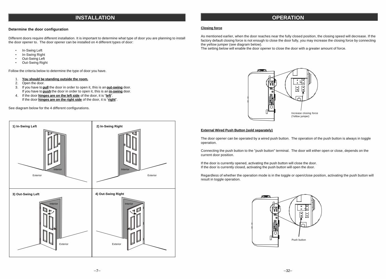
Determine the door configuration
Different doors require different installation. It is important to determine what type of door you are planning to installthe door opener to. The door opener can be installed on 4 different types of door:
• In-Swing Left• In-Swing Right• Out-Swing Left• Out-Swing Right
Follow the criteria below to determine the type of door you have.
1. You should be standing outside the room.2. Open the door.3. If you have to pull the door in order to open it, this is an out-swing door.
If you have to push the door in order to open it, this is an in-swing door.4. If the door hinges are on the left side of the door, it is “left”.
If the door hinges are on the right side of the door, it is “right”.
See diagram below for the 4 different configurations.
3) Out-Swing Left 4) Out-Swing Right
1) In-Swing Left 2) In-Swing Right
Interior
Exterior
Interior
Exterior
Interior
Exterior
Interior
Exterior
INSTALLATION
–7– –32–
Closing force
As mentioned earlier, when the door reaches near the fully closed position, the closing speed will decrease. If thefactory default closing force is not enough to close the door fully, you may increase the closing force by connectingthe yellow jumper (see diagram below).The setting below will enable the door opener to close the door with a greater amount of force.
External Wired Push Button (sold separately)
The door opener can be operated by a wired push button. The operation of the push button is always in toggleoperation.
Connecting the push button to the "push button" terminal. The door will either open or close, depends on thecurrent door position.
If the door is currently opened, activating the push button will close the door.If the door is currently closed, activating the push button will open the door.
Regardless of whether the operation mode is in the toggle or open/close position, activating the push button willresult in toggle operation.
Push button
Increase closing force(Yellow jumper)
OPERATION
–8–
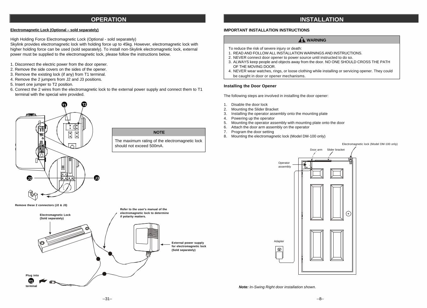
IMPORTANT INSTALLATION INSTRUCTIONS
To reduce the risk of severe injury or death:1. READ AND FOLLOW ALL INSTALLATION WARNINGS AND INSTRUCTIONS.2. NEVER connect door opener to power source until instructed to do so.3. ALWAYS keep people and objects away from the door. NO ONE SHOULD CROSS THE PATH
OF THE MOVING DOOR.4. NEVER wear watches, rings, or loose clothing while installing or servicing opener. They could
be caught in door or opener mechanisms.
Installing the Door Opener
The following steps are involved in installing the door opener:
1. Disable the door lock2. Mounting the Slider Bracket3. Installing the operator assembly onto the mounting plate4. Powering up the operator5. Mounting the operator assembly with mounting plate onto the door6. Attach the door arm assembly on the operator7. Program the door setting8. Mounting the electromagnetic lock (Model DM-100 only)
Note: In-Swing Right door installation shown.
WARNING
TODOROTM
Slider bracket
Operatorassembly
Electromagnetic lock (Model DM-100 only)
Door arm
Adapter
INSTALLATION
–31–
Electromagnetic Lock (Optional – sold separately)
High Holding Force Electromagnetic Lock (Optional - sold separately)Skylink provides electromagnetic lock with holding force up to 45kg. However, electromagnetic lock withhigher holding force can be used (sold separately). To install non-Skylink electromagnetic lock, externalpower must be supplied to the electromagnetic lock, please follow the instructions below.
1. Disconnect the electric power from the door opener.2. Remove the side covers on the sides of the opener.3. Remove the existing lock (if any) from T1 terminal.4. Remove the 2 jumpers from J2 and J3 positions.5. Insert one jumper to T2 position.6. Connect the 2 wires from the electromagnetic lock to the external power supply and connect them to T1
terminal with the special wire provided.
The maximum rating of the electromagnetic lockshould not exceed 500mA.
NOTE
Remove these 2 connectors (J2 & J3)
T2T1
Electromagnetic Lock(Sold separately)
Plug into
terminal
External power supplyfor electromagnetic lock(Sold separately)
Refer to the user's manual of theelectromagnetic lock to determineif polarity matters.
OPERATION
T1
J2 J3
–9–
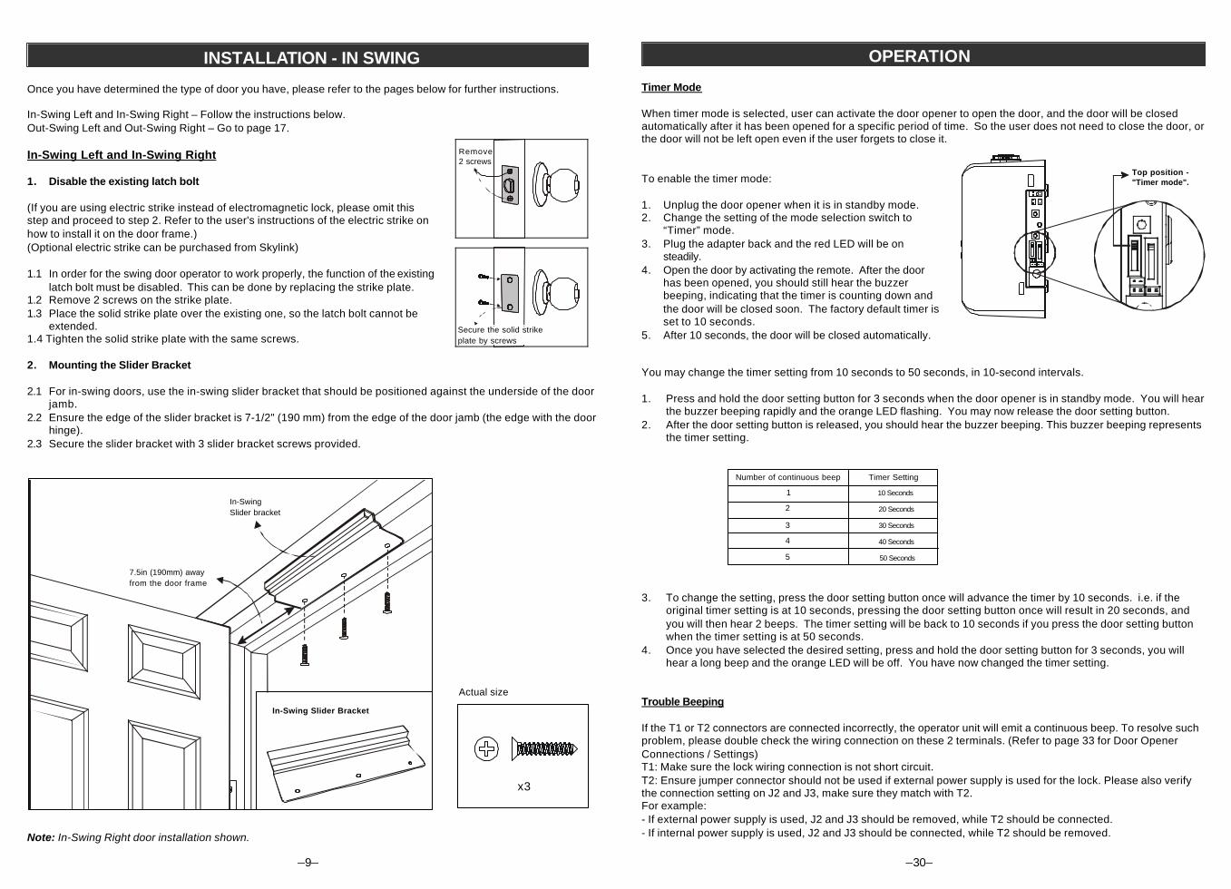
Once you have determined the type of door you have, please refer to the pages below for further instructions.
In-Swing Left and In-Swing Right – Follow the instructions below.Out-Swing Left and Out-Swing Right – Go to page 17.
In-Swing Left and In-Swing Right
1. Disable the existing latch bolt
(If you are using electric strike instead of electromagnetic lock, please omit thisstep and proceed to step 2. Refer to the user's instructions of the electric strike onhow to install it on the door frame.)(Optional electric strike can be purchased from Skylink)
1.1 In order for the swing door operator to work properly, the function of the existinglatch bolt must be disabled. This can be done by replacing the strike plate.
1.2 Remove 2 screws on the strike plate.1.3 Place the solid strike plate over the existing one, so the latch bolt cannot be
extended.1.4 Tighten the solid strike plate with the same screws.
2. Mounting the Slider Bracket
2.1 For in-swing doors, use the in-swing slider bracket that should be positioned against the underside of the doorjamb.
2.2 Ensure the edge of the slider bracket is 7-1/2" (190 mm) from the edge of the door jamb (the edge with the doorhinge).
2.3 Secure the slider bracket with 3 slider bracket screws provided.
Note: In-Swing Right door installation shown.
In-SwingSlider bracket
Secure the solid strikeplate by screws
INSTALLATION - IN SWING
x3
Actual size
Remove2 screws
In-Swing Slider Bracket
7.5in (190mm) awayfrom the door frame
–30–
OPERATION
You may change the timer setting from 10 seconds to 50 seconds, in 10-second intervals.
1. Press and hold the door setting button for 3 seconds when the door opener is in standby mode. You will hearthe buzzer beeping rapidly and the orange LED flashing. You may now release the door setting button.
2. After the door setting button is released, you should hear the buzzer beeping. This buzzer beeping representsthe timer setting.
3. To change the setting, press the door setting button once will advance the timer by 10 seconds. i.e. if theoriginal timer setting is at 10 seconds, pressing the door setting button once will result in 20 seconds, andyou will then hear 2 beeps. The timer setting will be back to 10 seconds if you press the door setting buttonwhen the timer setting is at 50 seconds.
4. Once you have selected the desired setting, press and hold the door setting button for 3 seconds, you willhear a long beep and the orange LED will be off. You have now changed the timer setting.
Trouble Beeping
If the T1 or T2 connectors are connected incorrectly, the operator unit will emit a continuous beep. To resolve suchproblem, please double check the wiring connection on these 2 terminals. (Refer to page 33 for Door OpenerConnections / Settings)T1: Make sure the lock wiring connection is not short circuit.T2: Ensure jumper connector should not be used if external power supply is used for the lock. Please also verifythe connection setting on J2 and J3, make sure they match with T2.For example:- If external power supply is used, J2 and J3 should be removed, while T2 should be connected.- If internal power supply is used, J2 and J3 should be connected, while T2 should be removed.
1
Timer Setting
10 Seconds
2
3
4
5
20 Seconds
30 Seconds
40 Seconds
50 Seconds
Number of continuous beep
Timer Mode When timer mode is selected, user can activate the door opener to open the door, and the door will be closedautomatically after it has been opened for a specific period of time. So the user does not need to close the door, orthe door will not be left open even if the user forgets to close it.
To enable the timer mode:
1. Unplug the door opener when it is in standby mode.2. Change the setting of the mode selection switch to
“Timer” mode.3. Plug the adapter back and the red LED will be on
steadily.4. Open the door by activating the remote. After the door
has been opened, you should still hear the buzzerbeeping, indicating that the timer is counting down andthe door will be closed soon. The factory default timer isset to 10 seconds.
5. After 10 seconds, the door will be closed automatically.
Top position -"Timer mode".
–10–
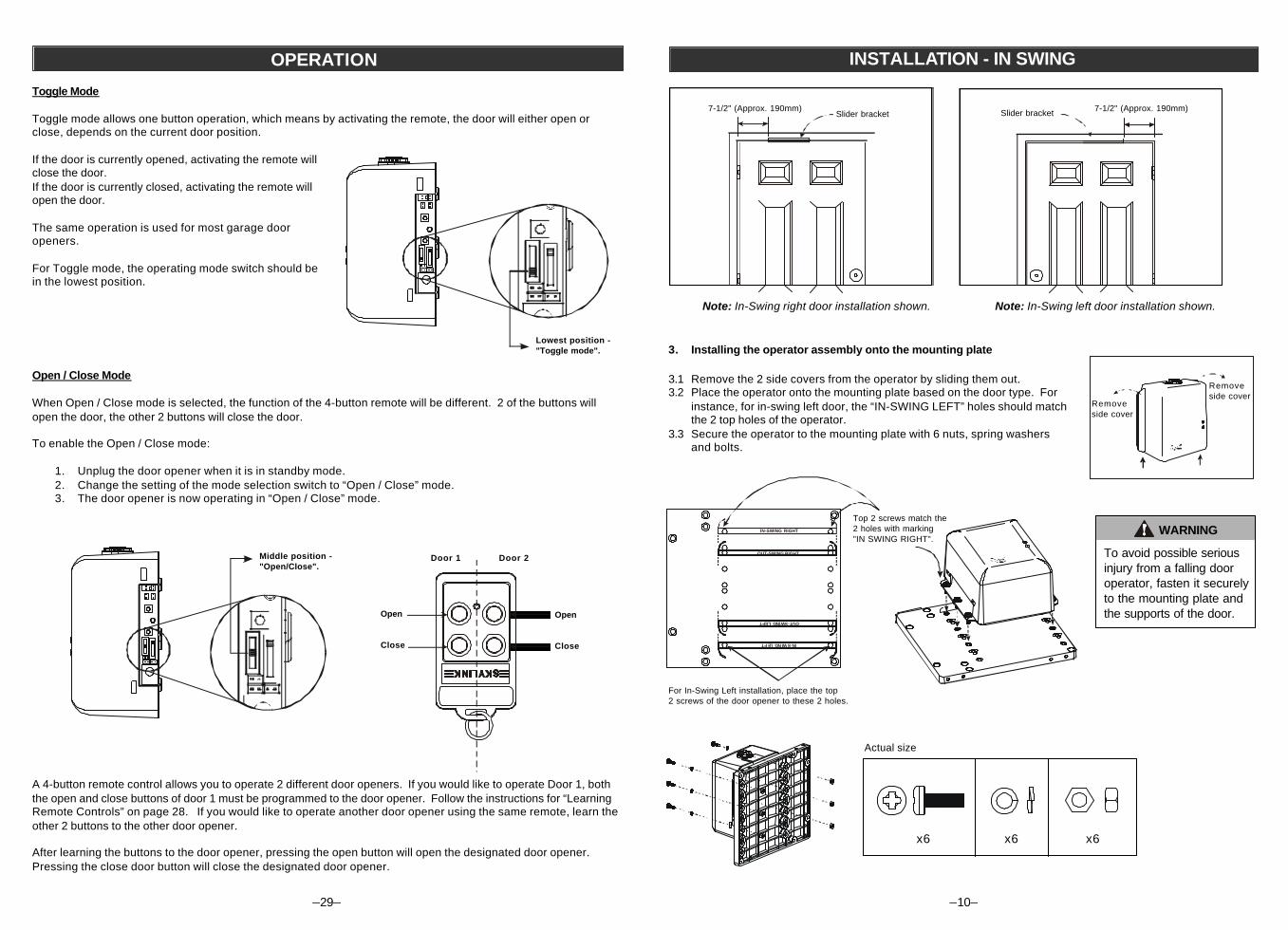
Slider bracket7-1/2" (Approx. 190mm)
3. Installing the operator assembly onto the mounting plate
3.1 Remove the 2 side covers from the operator by sliding them out.3.2 Place the operator onto the mounting plate based on the door type. For
instance, for in-swing left door, the “IN-SWING LEFT” holes should matchthe 2 top holes of the operator.
3.3 Secure the operator to the mounting plate with 6 nuts, spring washersand bolts.
Slider bracket
Note: In-Swing right door installation shown. Note: In-Swing left door installation shown.
For In-Swing Left installation, place the top2 screws of the door opener to these 2 holes.
WARNING
To avoid possible seriousinjury from a falling dooroperator, fasten it securelyto the mounting plate andthe supports of the door.
IN-SWING RIGHT
IN-SWING LEFT
OUT-SWING RIGHT
OUT-SWING LEFT
Top 2 screws match the2 holes with marking"IN SWING RIGHT".
INSTALLATION - IN SWING
7-1/2" (Approx. 190mm)
x6 x6 x6
Actual size
Removeside cover
Removeside cover
OPERATION
Open / Close Mode
When Open / Close mode is selected, the function of the 4-button remote will be different. 2 of the buttons willopen the door, the other 2 buttons will close the door.
To enable the Open / Close mode:
1. Unplug the door opener when it is in standby mode.2. Change the setting of the mode selection switch to “Open / Close” mode.3. The door opener is now operating in “Open / Close” mode.
A 4-button remote control allows you to operate 2 different door openers. If you would like to operate Door 1, boththe open and close buttons of door 1 must be programmed to the door opener. Follow the instructions for “LearningRemote Controls” on page 28. If you would like to operate another door opener using the same remote, learn theother 2 buttons to the other door opener.
After learning the buttons to the door opener, pressing the open button will open the designated door opener.Pressing the close door button will close the designated door opener.
Door 1 Door 2
Open
Close
Open
Close
Middle position -"Open/Close".
Toggle Mode
Toggle mode allows one button operation, which means by activating the remote, the door will either open orclose, depends on the current door position.
If the door is currently opened, activating the remote willclose the door.If the door is currently closed, activating the remote willopen the door.
The same operation is used for most garage dooropeners.
For Toggle mode, the operating mode switch should bein the lowest position.
–29–
Lowest position -"Toggle mode".
–11–
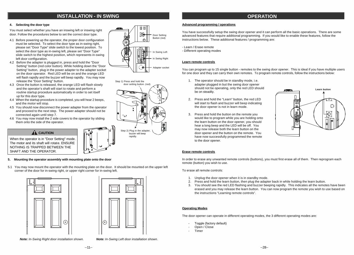
4. Selecting the door type
You must select whether you have an inswing left or inswing rightdoor. Follow the procedures below to set the correct door type.
4.1 Before powering up the operator, the proper door configurationmust be selected. To select the door type as in-swing right,please set “Door Type” slide switch to the lowest position. Toselect the door type as in-swing left, please set “Door Type”slide switch to the highest position, which represents in-swingleft door configuration.
4.2 Before the adapter is plugged in, press and hold the "DoorSetting" button (red color button). While holding down the "DoorSetting" button, plug in the power adapter to the adapter socketon the door operator. Red LED will be on and the orange LEDwill flash rapidly and the buzzer will beep rapidly. You may nowrelease the “Door Setting” button.
4.3 Once the button is released, the orange LED will flash slowlyand the operator’s shaft will start to rotate and perform aroutine startup procedure automatically in order to set itselfup for this door type.
4.4 When the startup procedure is completed, you will hear 2 beeps,and the motor will stop.
4.5 You should now disconnect the power adapter from the operatorand proceed to the next step. The power adapter should not beconnected again until step 7.
4.6 You may now install the 2 side covers to the operator by slidingthem onto the side of the operator.
CAUTION
When the operator is in "Door Setting" mode.The motor and its shaft will rotate. ENSURENOTHING IS TRAPPED BETWEEN THESHAFT AND THE OPERATOR.
INSTALLATION - IN SWING
Door SettingButton (red)
5. Mounting the operator assembly with mounting plate onto the door
5.1 You may now mount the operator with the mounting plate on the door. It should be mounted on the upper leftcorner of the door for in-swing right, or upper right corner for in-swing left.
TODORO TM
Note: In-Swing Right door installation shown. Note: In-Swing Left door installation shown.
TODORO TM
In Swing Right
Adapter socket
In Swing Left
Step 1) Press and hold thedoor setting button. (red)
Step 2) Plug in the adapter,buzzer will beeprapidly.
–28–
OPERATION
Advanced programming / operations
You have successfully setup the swing door opener and it can perform all the basic operations. There are someadvanced features that require additional programming. If you would like to enable these features, follow theinstructions below. These additional features / programming are:
- Learn / Erase remote- Different operating modes
Learn remote controls
You can program up to 15 single button - remotes to the swing door opener. This is ideal if you have multiple usersfor one door and they can carry their own remotes. To program remote controls, follow the instructions below:
1. The operator should be in standby mode, i.e.adapter plugged in but the swing door openershould not be operating, only the red LED shouldbe on steadily.
2. Press and hold the “Learn” button, the red LEDwill start to flash and buzzer will beep indicatingthe door opener is not in learn mode.
3. Press and hold the button on the remote youwould like to program while you are holding ontothe learn button on the door opener, you shouldhear a long beep and the LED will be off. Youmay now release both the learn button on thedoor opener and the button on the remote. Youhave now successfully programmed the remoteto the door opener.
Erase remote controls
In order to erase any unwanted remote controls (buttons), you must first erase all of them. Then reprogram eachremote (button) you wish to use.
To erase all remote controls:
1. Unplug the door opener when it is in standby mode.2. Press and hold the learn button, then plug the adapter back in while holding the learn button.3. You should see the red LED flashing and buzzer beeping rapidly. This indicates all the remotes have been
erased and you may release the learn button. You can now program the remote you wish to use based onthe instructions “Learning remote controls”.
Operating Modes
The door opener can operate in different operating modes, the 3 different operating modes are:
- Toggle (factory default)- Open / Close- Timer
Learn button

–12–
5.2 Locate the operator assembly 2mm away from the top of the door frame, and 2mm from the side.
INSTALLATION - IN SWING
5.3 Secure the mounting plate with 4 screws ontothe door.
x4
Actual size
x4
The lower hole should be used.
2mm
–27–
OPERATION
Mute
If you would like to disable the buzzer beeping when the door opener is operating, follow the procedures below.
· The door opener should be in standby mode, i.e. the red LED is on and the door is not moving.· Press and hold both the “Door Setting” and “Remote Learning” buttons, until a long beep is emitted
(approx. 3 seconds), then release both buttons.· The buzzer is now disabled.
To enable the buzzer, repeat the procedures above.
Obstacle detection
The swing door operator has a built-in safety feature of obstacledetection. When the opener is operating and if the door hits an obstacle(it could be an object or a person), the operator will stop.
To start the operator again, you must clear the obstacle from the doorand activate the remote again.
Test the obstacle detection system
In order to test the obstacle detection, place an obstacle with weight ofapprox 30 lbs (any small furniture, or a 3/4 filled 5-gallon bucket of water)in the middle of the door travel, i.e. 45 degrees from the fully closedposition (assuming the door travel is 90 degrees). Try this on bothopening and closing cycles to see if the door stops when it hits theobstacle. If the door doesn’t stop when it hits the obstacle, pleasecontact us.
WARNING
• Obstacle detection system must be tested every month.• After any adjustments are made, the obstacle detection system must be tested.
Any objectaprox. 30 lbs.
Power failure
During power failure, the remote control and the electromagnetic lock will not work. However, the door can still beopened or closed manually by pushing and pulling the door.
When the door is manually opened or closed and the clutch engages and disengages it will make a clicking sound.It is normal that more force is required to open / close the door due to the force generated by the clutch.
NOTE
During power failure, although the door can still be opened and closed, but the electromagnetic lock willnot function. When power resumes, the electromagnetic lock will function after a fully closed operation isperformed.
Gap between the door anddoor frame.
2mm
For Inswing Left, plugs in the extension cord for theelectromagnetic lock to the 2 most up left jupmers.
–13–
INSTALLATION - IN SWING
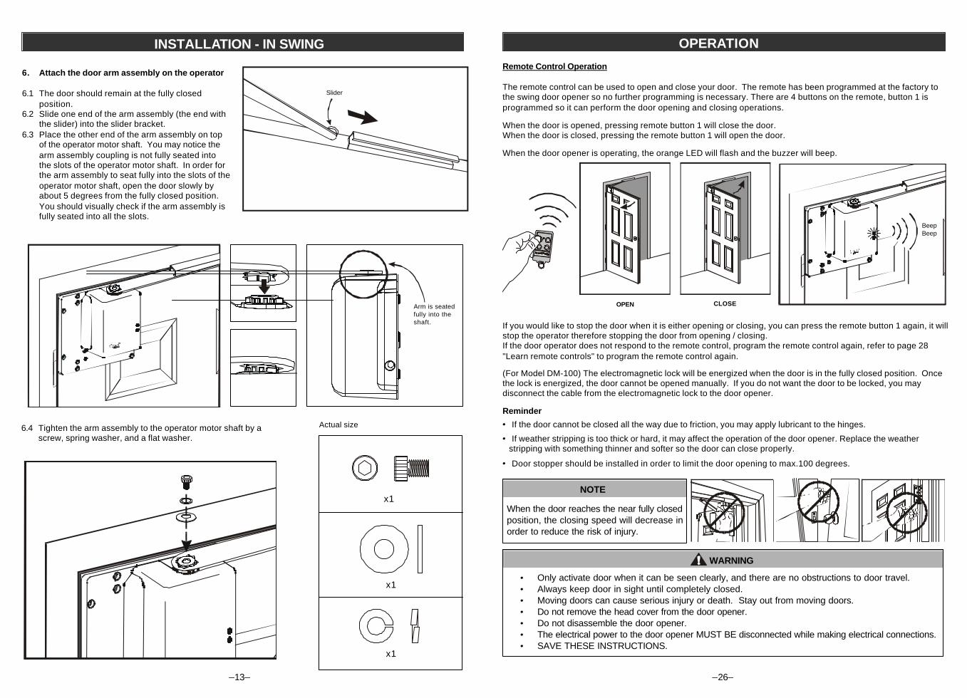
6. Attach the door arm assembly on the operator
6.1 The door should remain at the fully closedposition.
6.2 Slide one end of the arm assembly (the end withthe slider) into the slider bracket.
6.3 Place the other end of the arm assembly on topof the operator motor shaft. You may notice thearm assembly coupling is not fully seated intothe slots of the operator motor shaft. In order forthe arm assembly to seat fully into the slots of theoperator motor shaft, open the door slowly byabout 5 degrees from the fully closed position.You should visually check if the arm assembly isfully seated into all the slots.
Arm is seatedfully into theshaft.
Slider
6.4 Tighten the arm assembly to the operator motor shaft by ascrew, spring washer, and a flat washer.
x1
x1
x1
Actual size
–26–
OPERATION
Remote Control Operation
The remote control can be used to open and close your door. The remote has been programmed at the factory tothe swing door opener so no further programming is necessary. There are 4 buttons on the remote, button 1 isprogrammed so it can perform the door opening and closing operations.
When the door is opened, pressing remote button 1 will close the door.When the door is closed, pressing the remote button 1 will open the door.
When the door opener is operating, the orange LED will flash and the buzzer will beep.
OPEN CLOSE
(For Model DM-100) The electromagnetic lock will be energized when the door is in the fully closed position. Oncethe lock is energized, the door cannot be opened manually. If you do not want the door to be locked, you maydisconnect the cable from the electromagnetic lock to the door opener.
Reminder
· If the door cannot be closed all the way due to friction, you may apply lubricant to the hinges.
· If weather stripping is too thick or hard, it may affect the operation of the door opener. Replace the weather stripping with something thinner and softer so the door can close properly.
· Door stopper should be installed in order to limit the door opening to max.100 degrees.
If you would like to stop the door when it is either opening or closing, you can press the remote button 1 again, it willstop the operator therefore stopping the door from opening / closing.If the door operator does not respond to the remote control, program the remote control again, refer to page 28"Learn remote controls" to program the remote control again.
NOTE
When the door reaches the near fully closedposition, the closing speed will decrease inorder to reduce the risk of injury.
WARNING
· Only activate door when it can be seen clearly, and there are no obstructions to door travel.· Always keep door in sight until completely closed.· Moving doors can cause serious injury or death. Stay out from moving doors.· Do not remove the head cover from the door opener.· Do not disassemble the door opener.· The electrical power to the door opener MUST BE disconnected while making electrical connections.· SAVE THESE INSTRUCTIONS.
BeepBeep
–14–
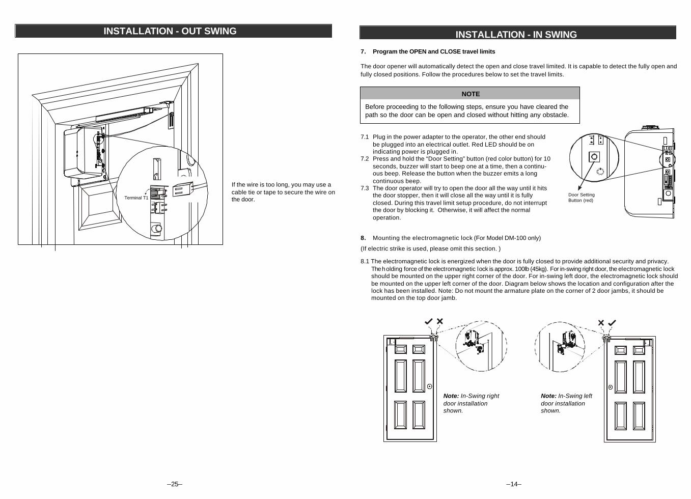
7.1 Plug in the power adapter to the operator, the other end shouldbe plugged into an electrical outlet. Red LED should be onindicating power is plugged in.
7.2 Press and hold the “Door Setting” button (red color button) for 10seconds, buzzer will start to beep one at a time, then a continu-ous beep. Release the button when the buzzer emits a longcontinuous beep.
7.3 The door operator will try to open the door all the way until it hitsthe door stopper, then it will close all the way until it is fullyclosed. During this travel limit setup procedure, do not interruptthe door by blocking it. Otherwise, it will affect the normaloperation.
INSTALLATION - IN SWING
NOTE
Before proceeding to the following steps, ensure you have cleared thepath so the door can be open and closed without hitting any obstacle.
Door SettingButton (red)
8. Mounting the electromagnetic lock (For Model DM-100 only)
(If electric strike is used, please omit this section. )
8.1 The electromagnetic lock is energized when the door is fully closed to provide additional security and privacy.The holding force of the electromagnetic lock is approx. 100lb (45kg). For in-swing right door, the electromagnetic lockshould be mounted on the upper right corner of the door. For in-swing left door, the electromagnetic lock shouldbe mounted on the upper left corner of the door. Diagram below shows the location and configuration after thelock has been installed. Note: Do not mount the armature plate on the corner of 2 door jambs, it should bemounted on the top door jamb.
T O D O RO TM
TODOR OTM
Note: In-Swing rightdoor installationshown.
Note: In-Swing leftdoor installationshown.
7. Program the OPEN and CLOSE travel limits
The door opener will automatically detect the open and close travel limited. It is capable to detect the fully open andfully closed positions. Follow the procedures below to set the travel limits.
–25–
INSTALLATION - OUT SWING
If the wire is too long, you may use acable tie or tape to secure the wire onthe door.Terminal T1
–15–
INSTALLATION - IN SWING
1
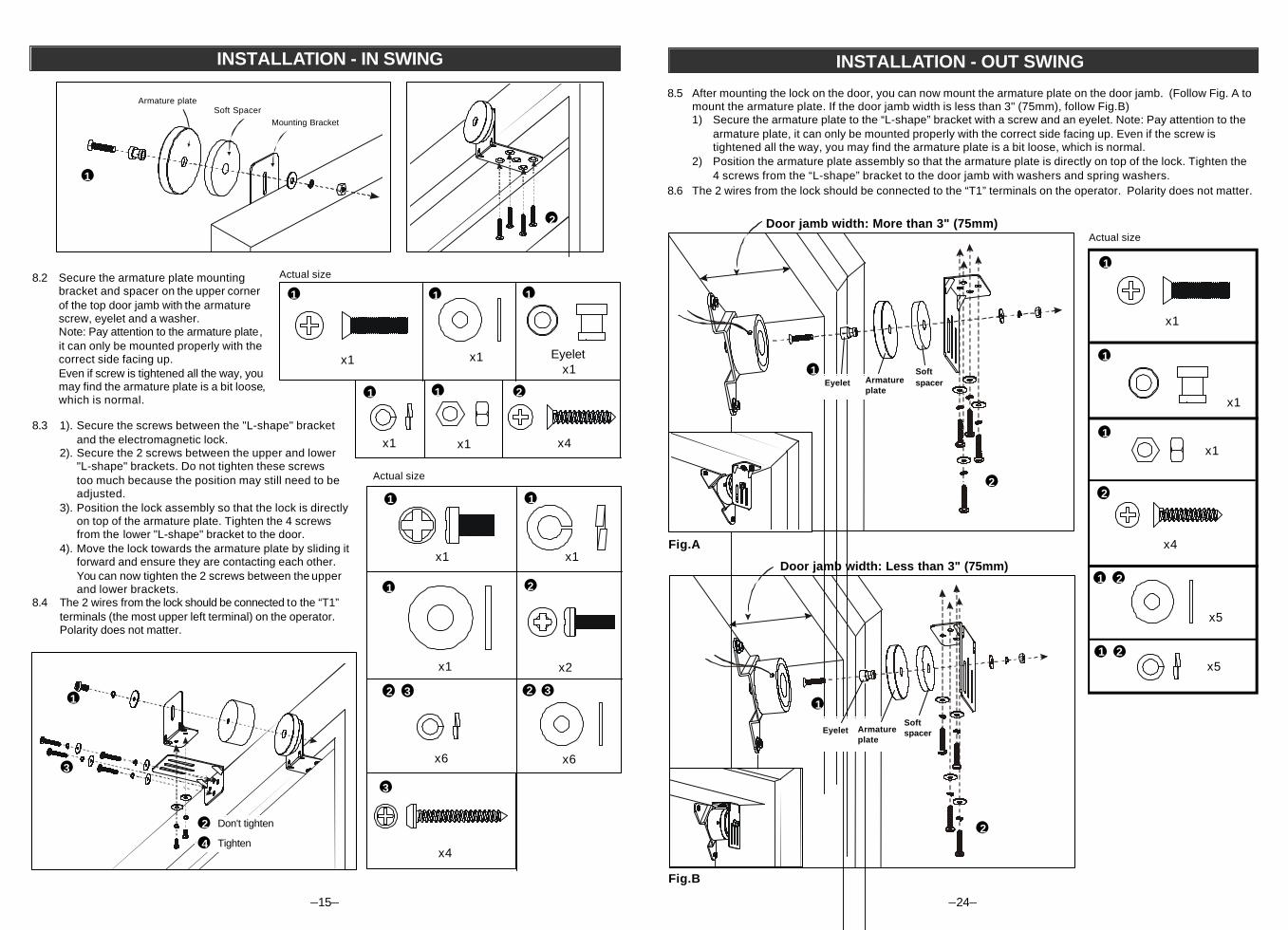
8.3 1). Secure the screws between the "L-shape" bracketand the electromagnetic lock.
2). Secure the 2 screws between the upper and lower"L-shape" brackets. Do not tighten these screwstoo much because the position may still need to beadjusted.
3). Position the lock assembly so that the lock is directlyon top of the armature plate. Tighten the 4 screwsfrom the lower "L-shape" bracket to the door.
4). Move the lock towards the armature plate by sliding itforward and ensure they are contacting each other.You can now tighten the 2 screws between the upperand lower brackets.
8.4 The 2 wires from the lock should be connected to the “T1”terminals (the most upper left terminal) on the operator.Polarity does not matter.
Actual size
8.2 Secure the armature plate mountingbracket and spacer on the upper cornerof the top door jamb with the armaturescrew, eyelet and a washer.Note: Pay attention to the armature plate,it can only be mounted properly with thecorrect side facing up.Even if screw is tightened all the way, youmay find the armature plate is a bit loose,which is normal.
x1
x1
x2
x1
x4
x6
2 3
1
1 2
2 3
3
1
x6
x4
Eyeletx1
Actual size
x1
2
1
2
11
x1
1
1
3
Armature plateSoft Spacer
x1 x1
11
2 Don't tighten
Tighten4
Mounting Bracket
–24–
INSTALLATION - OUT SWING
x1
x1
x5
x4
Actual size
1
1
32
2
x5
8.5 After mounting the lock on the door, you can now mount the armature plate on the door jamb. (Follow Fig. A tomount the armature plate. If the door jamb width is less than 3" (75mm), follow Fig.B)1) Secure the armature plate to the “L-shape” bracket with a screw and an eyelet. Note: Pay attention to the
armature plate, it can only be mounted properly with the correct side facing up. Even if the screw istightened all the way, you may find the armature plate is a bit loose, which is normal.
2) Position the armature plate assembly so that the armature plate is directly on top of the lock. Tighten the4 screws from the “L-shape” bracket to the door jamb with washers and spring washers.
8.6 The 2 wires from the lock should be connected to the “T1” terminals on the operator. Polarity does not matter.
Door jamb width: Less than 3" (75mm)
1
2
Armatureplate
EyeletSoftspacer
Door jamb width: More than 3" (75mm)
Fig.A
Fig.B
2
1Armatureplate
EyeletSoftspacer
x11
31
231
–16–
INSTALLATION - IN SWINGINSTALLATION - IN SWING
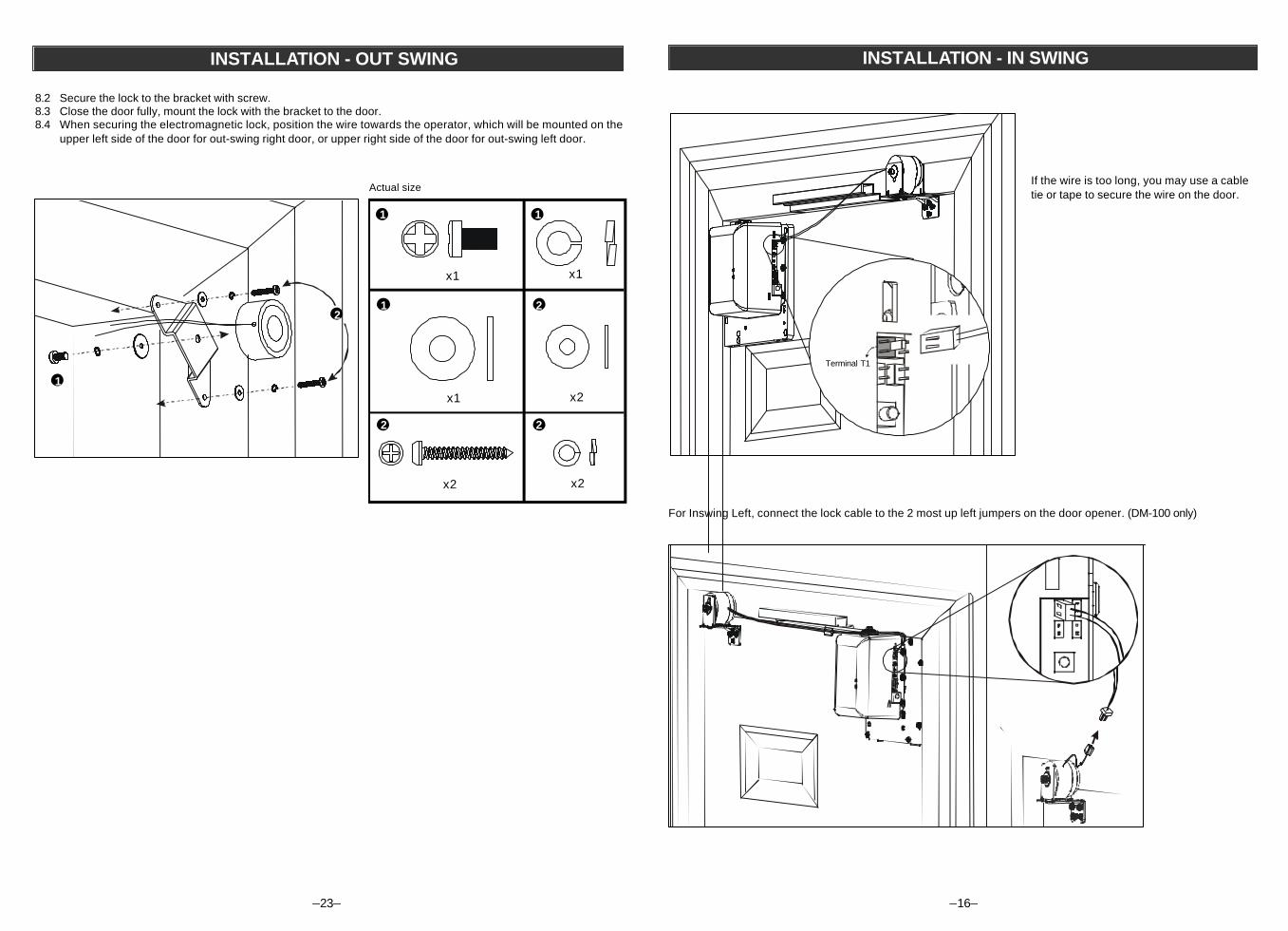
If the wire is too long, you may use a cabletie or tape to secure the wire on the door.
Terminal T1
–23–
INSTALLATION - OUT SWING
8.2 Secure the lock to the bracket with screw.8.3 Close the door fully, mount the lock with the bracket to the door.8.4 When securing the electromagnetic lock, position the wire towards the operator, which will be mounted on the
upper left side of the door for out-swing right door, or upper right side of the door for out-swing left door.
x1 x1
x1 x2
x2 x2
Actual size
1 1
1 22
2
1
2
For Inswing Left, connect the lock cable to the 2 most up left jumpers on the door opener. (DM-100 only)
–17–
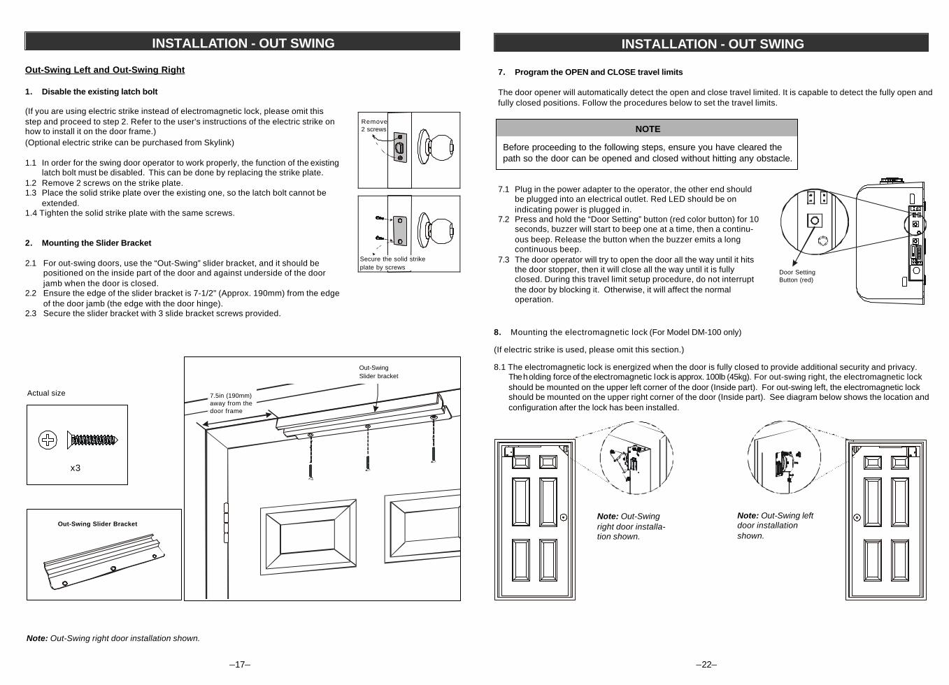
Out-Swing Left and Out-Swing Right
1. Disable the existing latch bolt
(If you are using electric strike instead of electromagnetic lock, please omit thisstep and proceed to step 2. Refer to the user's instructions of the electric strike onhow to install it on the door frame.)(Optional electric strike can be purchased from Skylink)
1.1 In order for the swing door operator to work properly, the function of the existinglatch bolt must be disabled. This can be done by replacing the strike plate.
1.2 Remove 2 screws on the strike plate.1.3 Place the solid strike plate over the existing one, so the latch bolt cannot be
extended.1.4 Tighten the solid strike plate with the same screws.
2. Mounting the Slider Bracket
2.1 For out-swing doors, use the “Out-Swing” slider bracket, and it should bepositioned on the inside part of the door and against underside of the doorjamb when the door is closed.
2.2 Ensure the edge of the slider bracket is 7-1/2" (Approx. 190mm) from the edgeof the door jamb (the edge with the door hinge).
2.3 Secure the slider bracket with 3 slide bracket screws provided.
INSTALLATION - OUT SWING
Note: Out-Swing right door installation shown.
Out-Swing Slider Bracket
x3
Actual size
Secure the solid strikeplate by screws
Remove2 screws
Out-SwingSlider bracket
7.5in (190mm)away from thedoor frame
–22–
INSTALLATION - OUT SWING
NOTE
Before proceeding to the following steps, ensure you have cleared thepath so the door can be opened and closed without hitting any obstacle.
8. Mounting the electromagnetic lock (For Model DM-100 only)
(If electric strike is used, please omit this section.)
8.1 The electromagnetic lock is energized when the door is fully closed to provide additional security and privacy.The holding force of the electromagnetic lock is approx. 100lb (45kg). For out-swing right, the electromagnetic lockshould be mounted on the upper left corner of the door (Inside part). For out-swing left, the electromagnetic lockshould be mounted on the upper right corner of the door (Inside part). See diagram below shows the location andconfiguration after the lock has been installed.
Note: Out-Swingright door installa-tion shown.
Note: Out-Swing leftdoor installationshown.
T O D O RO TM TODORO TM
Door SettingButton (red)
7.1 Plug in the power adapter to the operator, the other end shouldbe plugged into an electrical outlet. Red LED should be onindicating power is plugged in.
7.2 Press and hold the “Door Setting” button (red color button) for 10seconds, buzzer will start to beep one at a time, then a continu-ous beep. Release the button when the buzzer emits a longcontinuous beep.
7.3 The door operator will try to open the door all the way until it hitsthe door stopper, then it will close all the way until it is fullyclosed. During this travel limit setup procedure, do not interruptthe door by blocking it. Otherwise, it will affect the normaloperation.
7. Program the OPEN and CLOSE travel limits
The door opener will automatically detect the open and close travel limited. It is capable to detect the fully open andfully closed positions. Follow the procedures below to set the travel limits.
–18–
INSTALLATION - OUT SWING
Slider bracket Slider bracket
Note: Out-Swing right door installation shown. Note: Out-Swing left door installation shown.
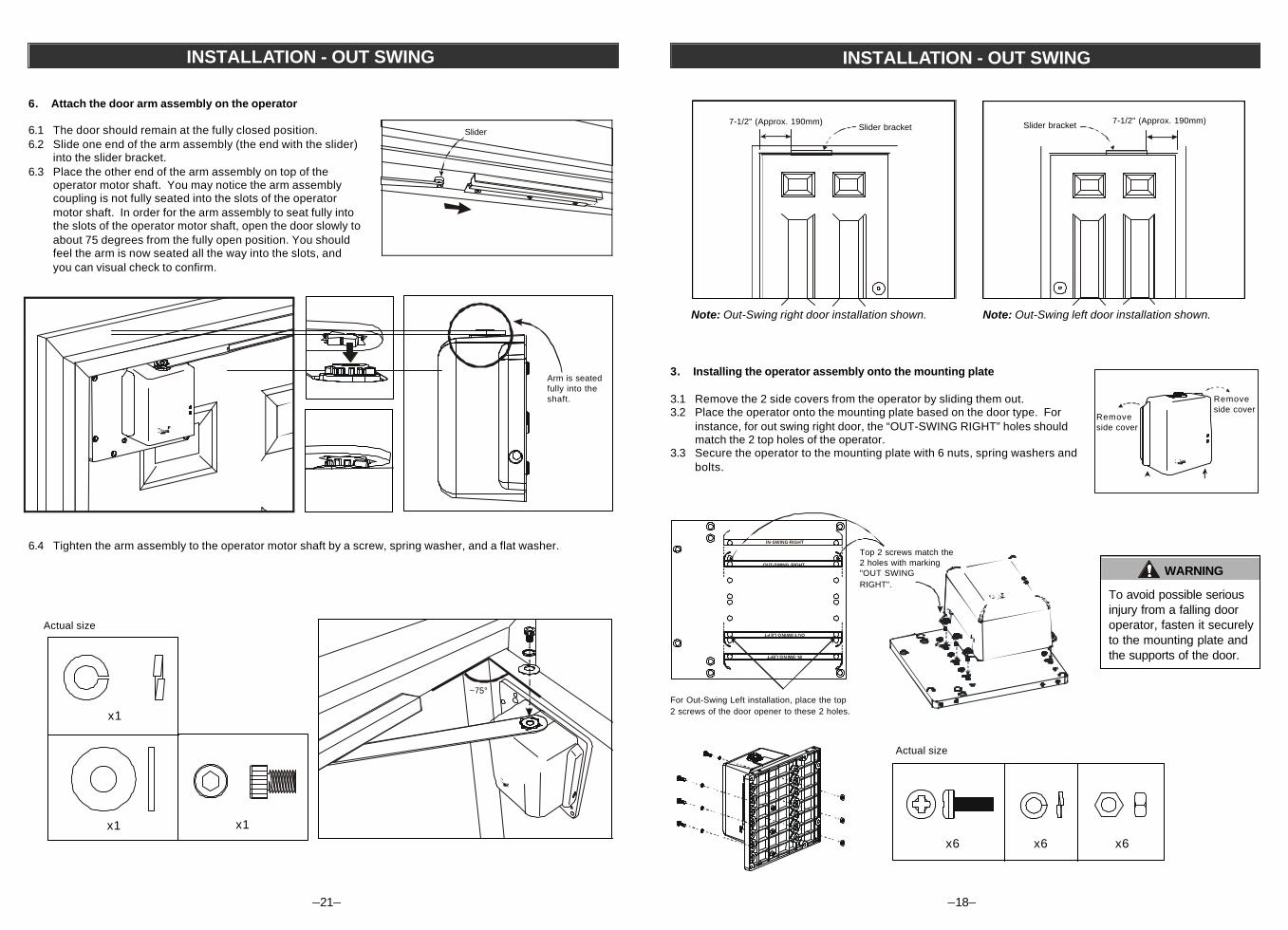
3. Installing the operator assembly onto the mounting plate
3.1 Remove the 2 side covers from the operator by sliding them out.3.2 Place the operator onto the mounting plate based on the door type. For
instance, for out swing right door, the “OUT-SWING RIGHT” holes shouldmatch the 2 top holes of the operator.
3.3 Secure the operator to the mounting plate with 6 nuts, spring washers andbolts.
For Out-Swing Left installation, place the top2 screws of the door opener to these 2 holes.
IN-SWING RIGHT
IN-SWING LEFT
OUT-SWING RIGHT
OUT-SWING LEFT
WARNING
To avoid possible seriousinjury from a falling dooroperator, fasten it securelyto the mounting plate andthe supports of the door.
Top 2 screws match the2 holes with marking"OUT SWINGRIGHT".
7-1/2" (Approx. 190mm)7-1/2" (Approx. 190mm)
Removeside cover
Removeside cover
Actual size
x6 x6 x6
–21–
INSTALLATION - OUT SWING
6. Attach the door arm assembly on the operator
6.1 The door should remain at the fully closed position.6.2 Slide one end of the arm assembly (the end with the slider)
into the slider bracket.6.3 Place the other end of the arm assembly on top of the
operator motor shaft. You may notice the arm assemblycoupling is not fully seated into the slots of the operatormotor shaft. In order for the arm assembly to seat fully intothe slots of the operator motor shaft, open the door slowly toabout 75 degrees from the fully open position. You shouldfeel the arm is now seated all the way into the slots, andyou can visual check to confirm.
Slider
6.4 Tighten the arm assembly to the operator motor shaft by a screw, spring washer, and a flat washer.
x1
x1x1
Actual size
Arm is seatedfully into theshaft.
~75°
–19–
INSTALLATION - OUT SWING
4. Selecting the door type
You must select whether you have an outswing left or outswing rightdoor. Follow the procedures below to set the correct door type.
4.1 Before powering up the operator, the proper door configura-tion must be selected. To select the door type as out-swingright, please set “Door Type” slide switch to 2 nd position fromthe top. To select the door type as out-swing left, pleaseset “Door Type” slide switch to the 3 rd position from the top.
4.2 Before the adapter is plugged in, press and hold the "DoorSetting" button (red color button). While holding down the "DoorSetting" button, plug in the power adapter to the adapter socketon the door operator. Red LED will be on and the orange LEDwill flash rapidly and the buzzer will beep rapidly. You may nowrelease the “Door Setting” button.
4.3 Once the button is released, the orange LED will flash slowlyand the operator’s shaft will start to rotate and perform aroutine startup procedure automatically in order to set itselfup for this door type.
4.4 When the startup procedure is completed, you will hear 2 beeps,and the motor will stop.
4.5 You should now disconnect the power adapter from the operatorand proceed to the next step. The power adapter should not beconnected again until step 7.
4.6 You may now install the 2 side covers to the operator by slidingthem onto the side of the operator.
5. Mounting the operator assembly with mounting plate onto the door
5.1 You may now mount the operator with the mounting plate on the door. It should be mounted on the upper leftcorner of the door for out-swing right, or upper right corner for out-swing left.
Note: Out-Swing Left door installation shown. Note: Out-Swing Right door installation shown.
TODOROTM
TODOROTM
CAUTION
When the operator is in "Door Setting" mode.The motor and its shaft will rotate. ENSURENOTHING IS TRAPPED BETWEEN THESHAFT AND THE OPERATOR.
Door SettingButton (red)
Out Swing Right
Adapter socket
Out Swing Left
Step 1) Press and hold thedoor setting button. (red)
Step 2) Plug in the adapter,buzzer will beeprapidly.
–20–
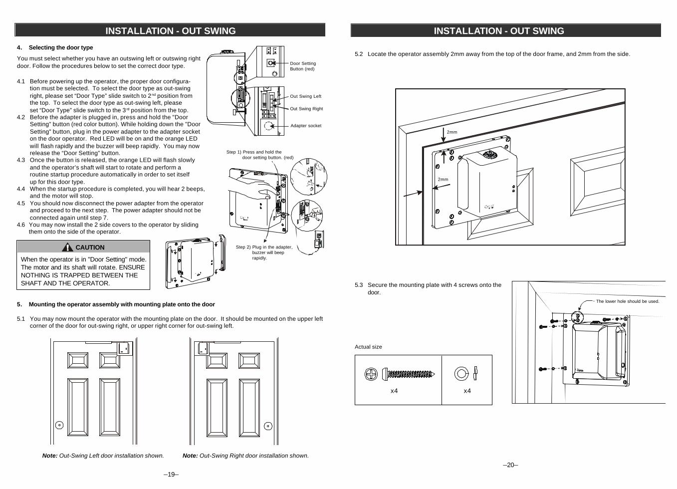
INSTALLATION - OUT SWING
5.3 Secure the mounting plate with 4 screws onto thedoor.
Actual size
The lower hole should be used.
2mm
2mm
x4 x4
5.2 Locate the operator assembly 2mm away from the top of the door frame, and 2mm from the side.