svc varistors type - samwha · introduction svc series varistors are gapless ceramic surge...
TRANSCRIPT
116
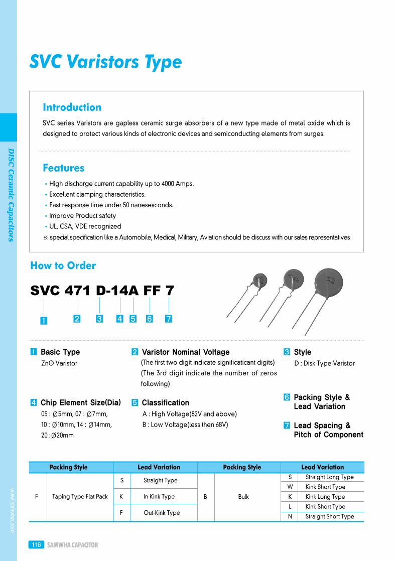
IntroductionSVC series Varistors are gapless ceramic surge absorbers of a new type made of metal oxide which is
designed to protect various kinds of electronic devices and semiconducting elements from surges.
FeaturesHigh discharge current capability up to 4000 Amps.
Excellent clamping characteristics.
Fast response time under 50 nanesesconds.
Improve Product safety
UL, CSA, VDE recognized
※ special specification like a Automobile, Medical, Military, Aviation should be discuss with our sales representatives
SVC Varistors Type
SVC 471 D-14A FF 7
How to Order
Basic Type
ZnO Varistor
Chip Element Size(Dia)
05 : Ø5mm, 07 : Ø7mm,
10 : Ø10mm, 14 : Ø14mm,
20 :Ø20mm
Varistor Nominal Voltage(The first two digit indicate significaticant digits)
(The 3rd digit indicate the number of zeros
following)
Classification
A : High Voltage(82V and above)
B : Low Voltage(less then 68V)
Packing Style Lead Variation Packing Style Lead VariationS Straight Long Type
W Kink Short Type
B Bulk K Kink Long Type
L Kink Short Type
N Straight Short Type
S Straight Type
F Taping Type Flat Pack K In-Kink Type
F Out-Kink Type
Style
D : Disk Type Varistor
Packing Style &Lead Variation
Lead Spacing &Pitch of Component
www.sam
wha.com
DISC
Ceram
ic Capacitors

DISC Ceramic Capacitors 117
Taping Type Bulk Type
Code Lead Spacing(mm) Pitch of Component(mm) Code Lead Spacing(mm)
5 5.0 12.7 5 5.0
7 7.5 15.0 7 7.5
8 7.5 30.0 1 10.0
9 7.5 25.4
1 10.0 30.0
SVC Characteristic CurvesV - Ⅰ Curve
Small - current region of V -Ⅰcurve Temporary power frequency over voltage capability
B Type
Withstand discharge impulse current
characteristics(Typical)
A Type
Withstand discharge impulse
current characteristics(Typical)
Suffix Code
SVC Varistors Type
118
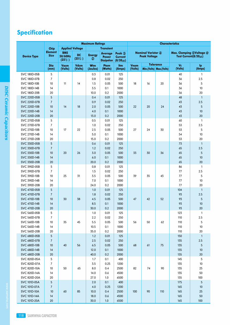
Specification
Maximum Ratings
Applied VoltageRMS
50/60Hz(25 )
Dia(mm)
Vacm(Volts)
Vdcm(Volts)
Wtm(Joules)
Ptam(Watts)
Itm(Amps)
Vnom(Volts) Min.(Volts) Max.(Volts)
Vc(Volts)
Ip(Amps)
Tolerance
ChipElement
Size DC(25 )
Energy②
AveragePower
Dissipation
Peak ③Current(8/20)
Nominal Varistor ④Peak Voltage
Max. Clamping ⑤Voltage @Test Current(8/20)
Transient
Characteristics
Device Type
SVC 180D-05B 5 0.3 0.01 125 40 1
SVC 180D-07B 7 0.8 0.02 250 36 2.5
SVC 180D-10B 10 11 14 1.5 0.05 500 18 16 20 36 5
SVC 180D-14B 14 3.5 0.1 1000 36 10
SVC 180D-20B 20 10.0 0.2 2000 36 20
SVC 220D-05B 5 0.4 0.01 125 48 1
SVC 220D-07B 7 0.9 0.02 250 43 2.5
SVC 220D-10B 10 14 18 2.0 0.05 500 22 20 24 43 5
SVC 220D-14B 14 4.0 0.1 1000 43 10
SVC 220D-20B 20 13.0 0.2 2000 43 20
SVC 270D-05B 5 0.5 0.01 125 60 1
SVC 270D-07B 7 1.0 0.02 250 53 2.5
SVC 270D-10B 10 17 22 2.5 0.05 500 27 24 30 53 5
SVC 270D-14B 14 5.0 0.1 1000 54 10
SVC 270D-20B 20 15.0 0.2 2000 53 20
SVC 330D-05B 5 0.6 0.01 125 73 1
SVC 330D-07B 7 1.2 0.02 250 65 2.5
SVC 330D-10B 10 20 26 3.0 0.05 500 33 30 36 65 5
SVC 330D-14B 14 6.0 0.1 1000 65 10
SVC 330D-20B 20 20.0 0.2 2000 65 20
SVC 390D-05B 5 0.8 0.01 125 86 1
SVC 390D-07B 7 1.5 0.02 250 77 2.5
SVC 390D-10B 10 25 31 3.5 0.05 500 39 35 43 77 5
SVC 390D-14B 14 7.0 0.1 1000 77 10
SVC 390D-20B 20 24.0 0.2 2000 77 20
SVC 470D-05B 5 1.0 0.01 125 104 1
SVC 470D-07B 7 1.8 0.02 250 93 2.5
SVC 470D-10B 10 30 38 4.5 0.05 500 47 42 52 93 5
SVC 470D-14B 14 8.5 0.1 1000 93 10
SVC 470D-20B 20 30.0 0.2 2000 93 20
SVC 560D-05B 5 1.0 0.01 125 123 1
SVC 560D-07B 7 2.2 0.02 250 110 2.5
SVC 560D-10B 10 35 45 5.5 0.05 500 56 50 62 110 5
SVC 560D-14B 14 10.5 0.1 1000 110 10
SVC 560D-20B 20 35.0 0.2 2000 110 20
SVC 680D-05B 5 1.2 0.01 125 150 1
SVC 680D-07B 7 2.5 0.02 250 135 2.5
SVC 680D-10B 10 40 56 6.5 0.05 500 68 61 75 135 5
SVC 680D-14B 14 12.0 0.1 1000 135 10
SVC 680D-20B 20 40.0 0.2 2000 135 20
SVC 820D-05A 5 1.7 0.1 400 145 5
SVC 820D-07A 7 3.5 0.25 1200 135 10
SVC 820D-10A 10 50 65 8.0 0.4 2500 82 74 90 135 25
SVC 820D-14A 14 14.0 0.6 4500 135 50
SVC 820D-20A 20 27.0 1.0 6500 135 100
SVC 101D-05A 5 2.0 0.1 400 175 5
SVC 101D-07A 7 4.0 0.25 1200 165 10
SVC 101D-10A 10 60 85 10.0 0.4 2500 100 90 110 165 25
SVC 101D-14A 14 18.0 0.6 4500 165 50
SVC 101D-20A 20 30.0 1.0 6500 165 100
www.sam
wha.com
DISC
Ceram
ic Capacitors
DISC Ceramic Capacitors 119
Maximum Ratings
Applied VoltageRMS
50/60Hz(25 )
Dia(mm)
Vacm(Volts)
Vdcm(Volts)
Wtm(Joules)
Ptam(Watts)
Itm(Amps)
Vnom(Volts) Min.(Volts) Max.(Volts)
Vc(Volts)
Ip(Amps)
Tolerance
ChipElement
Size DC(25 )
Energy②
AveragePower
Dissipation
Peak ③Current(8/20)
Nominal Varistor ④Peak Voltage
Max. Clamping ⑤Voltage @Test Current(8/20)
Transient
Characteristics
Device Type
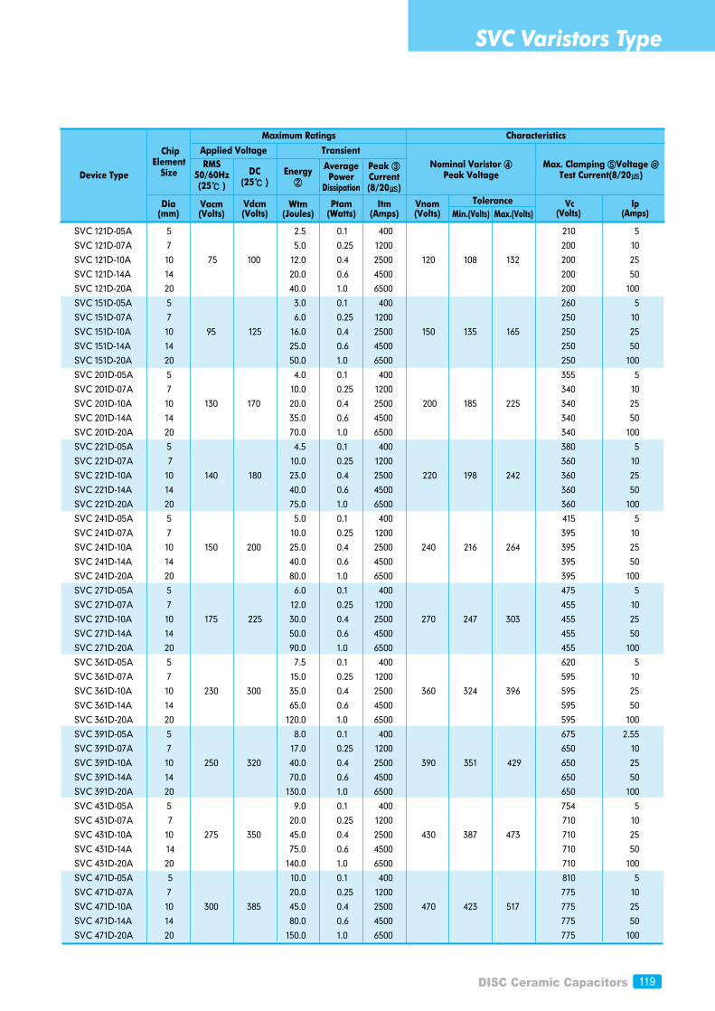
SVC 121D-05A 5 2.5 0.1 400 210 5
SVC 121D-07A 7 5.0 0.25 1200 200 10
SVC 121D-10A 10 75 100 12.0 0.4 2500 120 108 132 200 25
SVC 121D-14A 14 20.0 0.6 4500 200 50
SVC 121D-20A 20 40.0 1.0 6500 200 100
SVC 151D-05A 5 3.0 0.1 400 260 5
SVC 151D-07A 7 6.0 0.25 1200 250 10
SVC 151D-10A 10 95 125 16.0 0.4 2500 150 135 165 250 25
SVC 151D-14A 14 25.0 0.6 4500 250 50
SVC 151D-20A 20 50.0 1.0 6500 250 100
SVC 201D-05A 5 4.0 0.1 400 355 5
SVC 201D-07A 7 10.0 0.25 1200 340 10
SVC 201D-10A 10 130 170 20.0 0.4 2500 200 185 225 340 25
SVC 201D-14A 14 35.0 0.6 4500 340 50
SVC 201D-20A 20 70.0 1.0 6500 340 100
SVC 221D-05A 5 4.5 0.1 400 380 5
SVC 221D-07A 7 10.0 0.25 1200 360 10
SVC 221D-10A 10 140 180 23.0 0.4 2500 220 198 242 360 25
SVC 221D-14A 14 40.0 0.6 4500 360 50
SVC 221D-20A 20 75.0 1.0 6500 360 100
SVC 241D-05A 5 5.0 0.1 400 415 5
SVC 241D-07A 7 10.0 0.25 1200 395 10
SVC 241D-10A 10 150 200 25.0 0.4 2500 240 216 264 395 25
SVC 241D-14A 14 40.0 0.6 4500 395 50
SVC 241D-20A 20 80.0 1.0 6500 395 100
SVC 271D-05A 5 6.0 0.1 400 475 5
SVC 271D-07A 7 12.0 0.25 1200 455 10
SVC 271D-10A 10 175 225 30.0 0.4 2500 270 247 303 455 25
SVC 271D-14A 14 50.0 0.6 4500 455 50
SVC 271D-20A 20 90.0 1.0 6500 455 100
SVC 361D-05A 5 7.5 0.1 400 620 5
SVC 361D-07A 7 15.0 0.25 1200 595 10
SVC 361D-10A 10 230 300 35.0 0.4 2500 360 324 396 595 25
SVC 361D-14A 14 65.0 0.6 4500 595 50
SVC 361D-20A 20 120.0 1.0 6500 595 100
SVC 391D-05A 5 8.0 0.1 400 675 2.55
SVC 391D-07A 7 17.0 0.25 1200 650 10
SVC 391D-10A 10 250 320 40.0 0.4 2500 390 351 429 650 25
SVC 391D-14A 14 70.0 0.6 4500 650 50
SVC 391D-20A 20 130.0 1.0 6500 650 100
SVC 431D-05A 5 9.0 0.1 400 754 5
SVC 431D-07A 7 20.0 0.25 1200 710 10
SVC 431D-10A 10 275 350 45.0 0.4 2500 430 387 473 710 25
SVC 431D-14A 14 75.0 0.6 4500 710 50
SVC 431D-20A 20 140.0 1.0 6500 710 100
SVC 471D-05A 5 10.0 0.1 400 810 5
SVC 471D-07A 7 20.0 0.25 1200 775 10
SVC 471D-10A 10 300 385 45.0 0.4 2500 470 423 517 775 25
SVC 471D-14A 14 80.0 0.6 4500 775 50
SVC 471D-20A 20 150.0 1.0 6500 775 100
SVC Varistors Type
120
Maximum Ratings
Applied VoltageRMS
50/60Hz(25 )
Dia(mm)
Vacm(Volts)
Vdcm(Volts)
Wtm(Joules)
Ptam(Watts)
Itm(Amps)
Vnom(Volts) Min.(Volts) Max.(Volts)
Vc(Volts)
Ip(Amps)
Tolerance
ChipElement
Size DC(25 )
Energy②
AveragePower
Dissipation
Peak ③Current(8/20)
Nominal Varistor ④Peak Voltage
Max. Clamping ⑤Voltage @Test Current(8/20)
Transient
Characteristics
Device Type
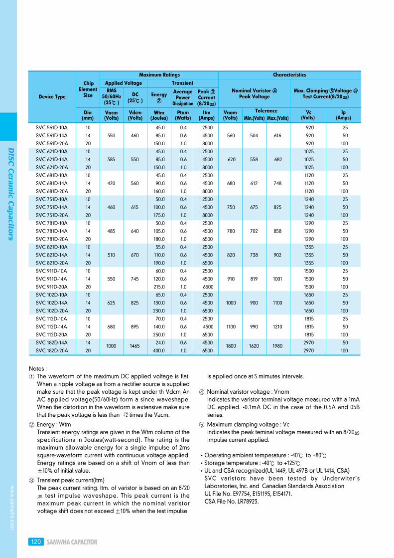
SVC 561D-10A 10 45.0 0.4 2500 920 25
SVC 561D-14A 14 350 460 85.0 0.6 4500 560 504 616 920 50
SVC 561D-20A 20 150.0 1.0 8000 920 100
SVC 621D-10A 10 45.0 0.4 2500 1025 25
SVC 621D-14A 14 385 550 85.0 0.6 4500 620 558 682 1025 50
SVC 621D-20A 20 150.0 1.0 8000 1025 100
SVC 681D-10A 10 45.0 0.4 2500 1120 25
SVC 681D-14A 14 420 560 90.0 0.6 4500 680 612 748 1120 50
SVC 681D-20A 20 160.0 1.0 8000 1120 100
SVC 751D-10A 10 50.0 0.4 2500 1240 25
SVC 751D-14A 14 460 615 100.0 0.6 4500 750 675 825 1240 50
SVC 751D-20A 20 175.0 1.0 8000 1240 100
SVC 781D-10A 10 50.0 0.4 2500 1290 25
SVC 781D-14A 14 485 640 105.0 0.6 4500 780 702 858 1290 50
SVC 781D-20A 20 180.0 1.0 6500 1290 100
SVC 821D-10A 10 55.0 0.4 2500 1355 25
SVC 821D-14A 14 510 670 110.0 0.6 4500 820 738 902 1355 50
SVC 821D-20A 20 190.0 1.0 6500 1355 100
SVC 911D-10A 10 60.0 0.4 2500 1500 25
SVC 911D-14A 14 550 745 120.0 0.6 4500 910 819 1001 1500 50
SVC 911D-20A 20 215.0 1.0 6500 1500 100
SVC 102D-10A 10 65.0 0.4 2500 1650 25
SVC 102D-14A 14 625 825 130.0 0.6 4500 1000 900 1100 1650 50
SVC 102D-20A 20 230.0 1.0 6500 1650 100
SVC 112D-10A 10 70.0 0.4 2500 1815 25
SVC 112D-14A 14 680 895 140.0 0.6 4500 1100 990 1210 1815 50
SVC 112D-20A 20 250.0 1.0 6500 1815 100
SVC 182D-14A 14 1000 1465
24.0 0.6 45001800 1620 1980
2970 50
SVC 182D-20A 20 400.0 1.0 6500 2970 100
Notes : ① The waveform of the maximum DC applied voltage is flat.
When a ripple voltage as from a rectifier source is suppliedmake sure that the peak voltage is kept under th Vdcm AnAC applied voltage(50/60Hz) form a since waveshape.When the distortion in the waveform is extensive make surethat the peak voltage is less than times the Vacm.
② Energy : WtmTransient energy ratings are given in the Wtm column of thespecifications in Joules(watt-second). The rating is themaximum allowable energy for a single impulse of 2mssquare-waveform current with continuous voltage applied.Energy ratings are based on a shift of Vnom of less than ±10% of initial value.
③ Transient peak current(Itm)The peak current rating. Itm. of varistor is based on an 8/20 test impulse waveshape. This peak current is themaximum peak current in which the nominal varistorvoltage shift does not exceed ±10% when the test impulse
is applied once at 5 mimutes intervals.
④ Nominal varistor voltage : VnomIndicates the varistor terminal voltage measured with a 1mADC applied. -0.1mA DC in the case of the 0.5A and 05Bseries.
⑤ Maximum clamping voltage : VcIndicates the peak teminal voltage measured with an 8/20impulse current applied.
Operating ambient temperature : -40 to +80Storage temperature : -40 to +125UL and CSA recognized(UL 1449, UL 497B or UL 1414, CSA)SVC varistors have been tested by Underwiter’sLaboratories, Inc. and Canadian Standards AssociationUL File No. E97754, E151195, E154171.CSA File No. LR78923.
www.sam
wha.com
DISC
Ceram
ic Capacitors
DISC Ceramic Capacitors 121
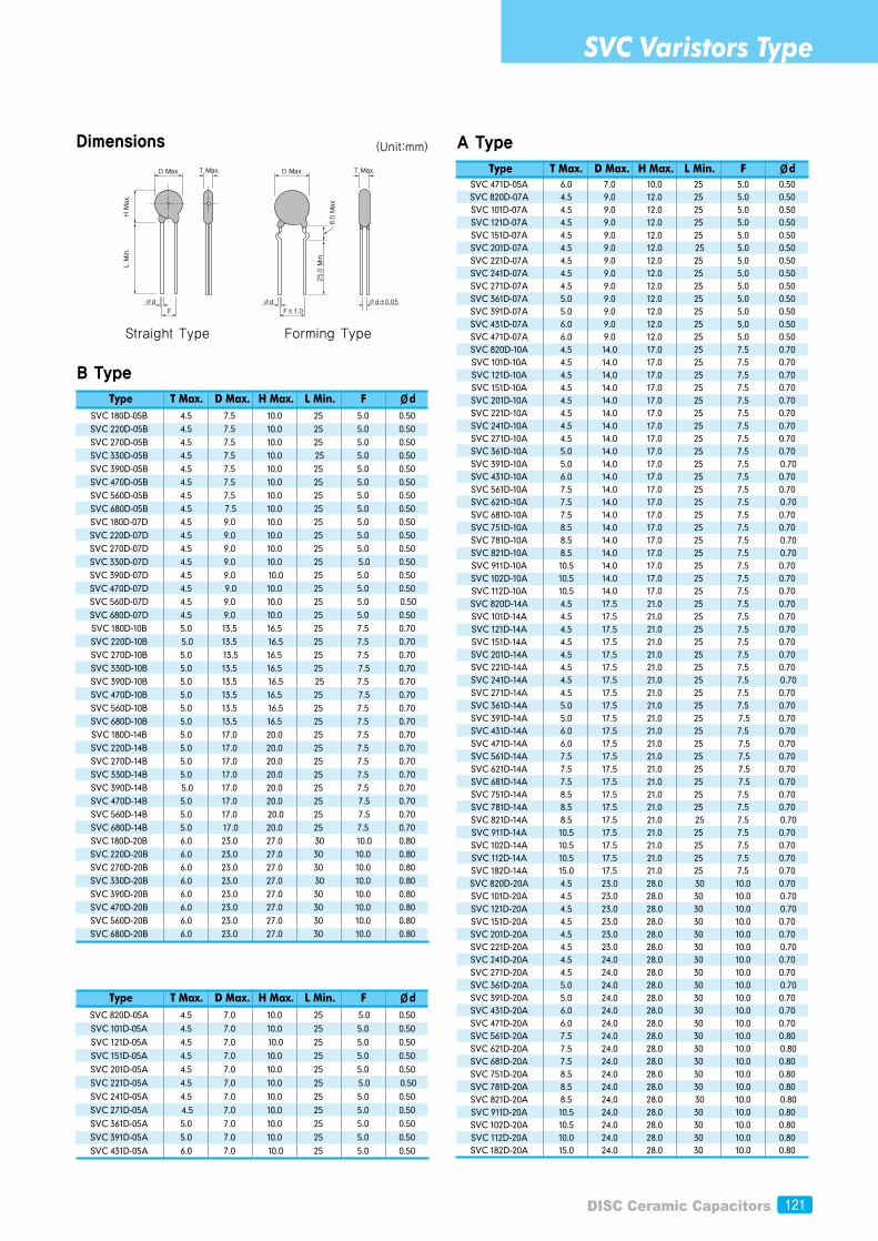
Dimensions
B Type
Straight Type Forming Type
Type T Max. D Max. H Max. L Min. F ØdSVC 180D-05B 4.5 7.5 10.0 25 5.0 0.50SVC 220D-05B 4.5 7.5 10.0 25 5.0 0.50SVC 270D-05B 4.5 7.5 10.0 25 5.0 0.50SVC 330D-05B 4.5 7.5 10.0 25 5.0 0.50SVC 390D-05B 4.5 7.5 10.0 25 5.0 0.50SVC 470D-05B 4.5 7.5 10.0 25 5.0 0.50SVC 560D-05B 4.5 7.5 10.0 25 5.0 0.50SVC 680D-05B 4.5 7.5 10.0 25 5.0 0.50SVC 180D-07D 4.5 9.0 10.0 25 5.0 0.50SVC 220D-07D 4.5 9.0 10.0 25 5.0 0.50SVC 270D-07D 4.5 9.0 10.0 25 5.0 0.50SVC 330D-07D 4.5 9.0 10.0 25 5.0 0.50SVC 390D-07D 4.5 9.0 10.0 25 5.0 0.50SVC 470D-07D 4.5 9.0 10.0 25 5.0 0.50SVC 560D-07D 4.5 9.0 10.0 25 5.0 0.50SVC 680D-07D 4.5 9.0 10.0 25 5.0 0.50SVC 180D-10B 5.0 13.5 16.5 25 7.5 0.70SVC 220D-10B 5.0 13.5 16.5 25 7.5 0.70SVC 270D-10B 5.0 13.5 16.5 25 7.5 0.70SVC 330D-10B 5.0 13.5 16.5 25 7.5 0.70SVC 390D-10B 5.0 13.5 16.5 25 7.5 0.70SVC 470D-10B 5.0 13.5 16.5 25 7.5 0.70SVC 560D-10B 5.0 13.5 16.5 25 7.5 0.70SVC 680D-10B 5.0 13.5 16.5 25 7.5 0.70SVC 180D-14B 5.0 17.0 20.0 25 7.5 0.70SVC 220D-14B 5.0 17.0 20.0 25 7.5 0.70SVC 270D-14B 5.0 17.0 20.0 25 7.5 0.70SVC 330D-14B 5.0 17.0 20.0 25 7.5 0.70SVC 390D-14B 5.0 17.0 20.0 25 7.5 0.70SVC 470D-14B 5.0 17.0 20.0 25 7.5 0.70SVC 560D-14B 5.0 17.0 20.0 25 7.5 0.70SVC 680D-14B 5.0 17.0 20.0 25 7.5 0.70SVC 180D-20B 6.0 23.0 27.0 30 10.0 0.80SVC 220D-20B 6.0 23.0 27.0 30 10.0 0.80SVC 270D-20B 6.0 23.0 27.0 30 10.0 0.80SVC 330D-20B 6.0 23.0 27.0 30 10.0 0.80SVC 390D-20B 6.0 23.0 27.0 30 10.0 0.80SVC 470D-20B 6.0 23.0 27.0 30 10.0 0.80SVC 560D-20B 6.0 23.0 27.0 30 10.0 0.80SVC 680D-20B 6.0 23.0 27.0 30 10.0 0.80
Type T Max. D Max. H Max. L Min. F ØdSVC 820D-05A 4.5 7.0 10.0 25 5.0 0.50
SVC 101D-05A 4.5 7.0 10.0 25 5.0 0.50
SVC 121D-05A 4.5 7.0 10.0 25 5.0 0.50
SVC 151D-05A 4.5 7.0 10.0 25 5.0 0.50
SVC 201D-05A 4.5 7.0 10.0 25 5.0 0.50
SVC 221D-05A 4.5 7.0 10.0 25 5.0 0.50
SVC 241D-05A 4.5 7.0 10.0 25 5.0 0.50
SVC 271D-05A 4.5 7.0 10.0 25 5.0 0.50
SVC 361D-05A 5.0 7.0 10.0 25 5.0 0.50
SVC 391D-05A 5.0 7.0 10.0 25 5.0 0.50
SVC 431D-05A 6.0 7.0 10.0 25 5.0 0.50
A Type
Type T Max. D Max. H Max. L Min. F ØdSVC 471D-05A 6.0 7.0 10.0 25 5.0 0.50SVC 820D-07A 4.5 9.0 12.0 25 5.0 0.50SVC 101D-07A 4.5 9.0 12.0 25 5.0 0.50SVC 121D-07A 4.5 9.0 12.0 25 5.0 0.50SVC 151D-07A 4.5 9.0 12.0 25 5.0 0.50SVC 201D-07A 4.5 9.0 12.0 25 5.0 0.50SVC 221D-07A 4.5 9.0 12.0 25 5.0 0.50SVC 241D-07A 4.5 9.0 12.0 25 5.0 0.50SVC 271D-07A 4.5 9.0 12.0 25 5.0 0.50SVC 361D-07A 5.0 9.0 12.0 25 5.0 0.50SVC 391D-07A 5.0 9.0 12.0 25 5.0 0.50SVC 431D-07A 6.0 9.0 12.0 25 5.0 0.50SVC 471D-07A 6.0 9.0 12.0 25 5.0 0.50SVC 820D-10A 4.5 14.0 17.0 25 7.5 0.70SVC 101D-10A 4.5 14.0 17.0 25 7.5 0.70SVC 121D-10A 4.5 14.0 17.0 25 7.5 0.70SVC 151D-10A 4.5 14.0 17.0 25 7.5 0.70SVC 201D-10A 4.5 14.0 17.0 25 7.5 0.70SVC 221D-10A 4.5 14.0 17.0 25 7.5 0.70SVC 241D-10A 4.5 14.0 17.0 25 7.5 0.70SVC 271D-10A 4.5 14.0 17.0 25 7.5 0.70SVC 361D-10A 5.0 14.0 17.0 25 7.5 0.70SVC 391D-10A 5.0 14.0 17.0 25 7.5 0.70SVC 431D-10A 6.0 14.0 17.0 25 7.5 0.70SVC 561D-10A 7.5 14.0 17.0 25 7.5 0.70SVC 621D-10A 7.5 14.0 17.0 25 7.5 0.70SVC 681D-10A 7.5 14.0 17.0 25 7.5 0.70SVC 751D-10A 8.5 14.0 17.0 25 7.5 0.70SVC 781D-10A 8.5 14.0 17.0 25 7.5 0.70SVC 821D-10A 8.5 14.0 17.0 25 7.5 0.70SVC 911D-10A 10.5 14.0 17.0 25 7.5 0.70SVC 102D-10A 10.5 14.0 17.0 25 7.5 0.70SVC 112D-10A 10.5 14.0 17.0 25 7.5 0.70SVC 820D-14A 4.5 17.5 21.0 25 7.5 0.70SVC 101D-14A 4.5 17.5 21.0 25 7.5 0.70SVC 121D-14A 4.5 17.5 21.0 25 7.5 0.70SVC 151D-14A 4.5 17.5 21.0 25 7.5 0.70SVC 201D-14A 4.5 17.5 21.0 25 7.5 0.70SVC 221D-14A 4.5 17.5 21.0 25 7.5 0.70SVC 241D-14A 4.5 17.5 21.0 25 7.5 0.70SVC 271D-14A 4.5 17.5 21.0 25 7.5 0.70SVC 361D-14A 5.0 17.5 21.0 25 7.5 0.70SVC 391D-14A 5.0 17.5 21.0 25 7.5 0.70SVC 431D-14A 6.0 17.5 21.0 25 7.5 0.70SVC 471D-14A 6.0 17.5 21.0 25 7.5 0.70SVC 561D-14A 7.5 17.5 21.0 25 7.5 0.70SVC 621D-14A 7.5 17.5 21.0 25 7.5 0.70SVC 681D-14A 7.5 17.5 21.0 25 7.5 0.70SVC 751D-14A 8.5 17.5 21.0 25 7.5 0.70SVC 781D-14A 8.5 17.5 21.0 25 7.5 0.70SVC 821D-14A 8.5 17.5 21.0 25 7.5 0.70SVC 911D-14A 10.5 17.5 21.0 25 7.5 0.70SVC 102D-14A 10.5 17.5 21.0 25 7.5 0.70SVC 112D-14A 10.5 17.5 21.0 25 7.5 0.70SVC 182D-14A 15.0 17.5 21.0 25 7.5 0.70SVC 820D-20A 4.5 23.0 28.0 30 10.0 0.70SVC 101D-20A 4.5 23.0 28.0 30 10.0 0.70SVC 121D-20A 4.5 23.0 28.0 30 10.0 0.70SVC 151D-20A 4.5 23.0 28.0 30 10.0 0.70SVC 201D-20A 4.5 23.0 28.0 30 10.0 0.70SVC 221D-20A 4.5 23.0 28.0 30 10.0 0.70SVC 241D-20A 4.5 24.0 28.0 30 10.0 0.70SVC 271D-20A 4.5 24.0 28.0 30 10.0 0.70SVC 361D-20A 5.0 24.0 28.0 30 10.0 0.70SVC 391D-20A 5.0 24.0 28.0 30 10.0 0.70SVC 431D-20A 6.0 24.0 28.0 30 10.0 0.70SVC 471D-20A 6.0 24.0 28.0 30 10.0 0.70SVC 561D-20A 7.5 24.0 28.0 30 10.0 0.80SVC 621D-20A 7.5 24.0 28.0 30 10.0 0.80SVC 681D-20A 7.5 24.0 28.0 30 10.0 0.80SVC 751D-20A 8.5 24.0 28.0 30 10.0 0.80SVC 781D-20A 8.5 24.0 28.0 30 10.0 0.80SVC 821D-20A 8.5 24.0 28.0 30 10.0 0.80SVC 911D-20A 10.5 24.0 28.0 30 10.0 0.80SVC 102D-20A 10.5 24.0 28.0 30 10.0 0.80SVC 112D-20A 10.0 24.0 28.0 30 10.0 0.80SVC 182D-20A 15.0 24.0 28.0 30 10.0 0.80
SVC Varistors Type
(Unit:mm)
122
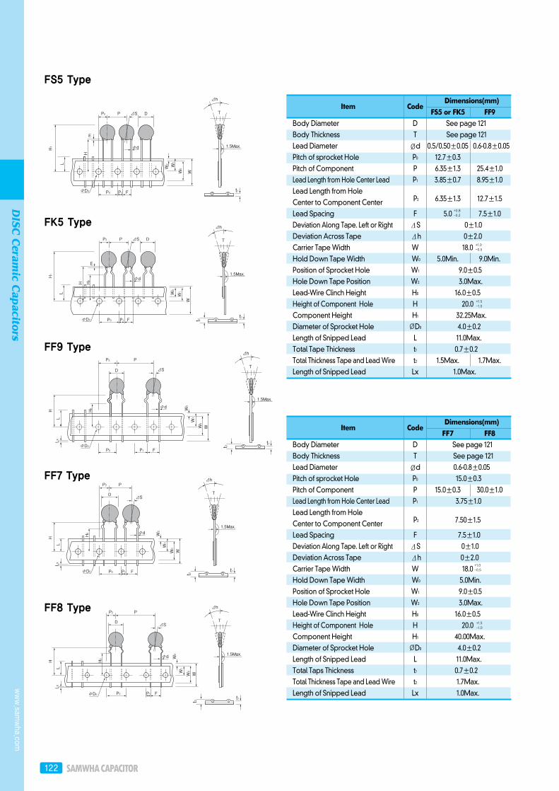
Item CodeFS5 or FK5 FF9
Body Diameter D See page 121Body Thickness T See page 121Lead Diameter Ød 0.5/0.50±0.05 0.6-0.8±0.05Pitch of sprocket Hole P0 12.7±0.3 Pitch of Component P 6.35±1.3 25.4±1.0Lead Length from Hole Center Lead P1 3.85±0.7 8.95±1.0Lead Length from Hole
P2 6.35±1.3 12.7±1.5Center to Component CenterLead Spacing F 5.0 7.5±1.0Deviation Along Tape. Left or Right ΔS 0±1.0 Deviation Across Tape Δh 0±2.0 Carrier Tape Width W 18.0 Hold Down Tape Width W0 5.0Min. 9.0Min.Position of Sprocket Hole W1 9.0±0.5 Hole Down Tape Position W2 3.0Max. Lead-Wire Clinch Height H0 16.0±0.5 Height of Component Hole H 20.0Component Height H1 32.25Max.Diameter of Sprocket Hole ØD0 4.0±0.2 Length of Snipped Lead L 11.0Max.Total Tape Thickness t1 0.7±0.2 Total Thickness Tape and Lead Wire t2 1.5Max. 1.7Max.Length of Snipped Lead Lx 1.0Max.
FS5 Type
FK5 Type
FF9 Type
FF7 Type
FF8 Type
+1.0 -0.5
+1.5 -1.0
+0.8 -0.2
Item CodeFF7 FF8
Body Diameter D See page 121Body Thickness T See page 121Lead Diameter Ød 0.6-0.8±0.05 Pitch of sprocket Hole P0 15.0±0.3 Pitch of Component P 15.0±0.3 30.0±1.0Lead Length from Hole Center Lead P1 3.75±1.0 Lead Length from Hole
P2 7.50±1.5 Center to Component CenterLead Spacing F 7.5±1.0Deviation Along Tape. Left or Right ΔS 0±1.0 Deviation Across Tape Δh 0±2.0 Carrier Tape Width W 18.0 Hold Down Tape Width W0 5.0Min. Position of Sprocket Hole W1 9.0±0.5 Hole Down Tape Position W2 3.0Max. Lead-Wire Clinch Height H0 16.0±0.5 Height of Component Hole H 20.0Component Height H1 40.00Max.Diameter of Sprocket Hole ØD0 4.0±0.2 Length of Snipped Lead L 11.0Max.Total Taps Thickness t1 0.7±0.2 Total Thickness Tape and Lead Wire t2 1.7Max.Length of Snipped Lead Lx 1.0Max.
+1.0 -0.5
+1.5 -1.0
www.sam
wha.com
DISC
Ceram
ic Capacitors
Dimensions(mm)
Dimensions(mm)
DISC Ceramic Capacitors 123
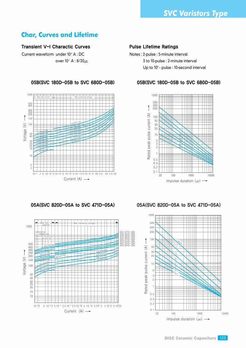
Char, Curves and Lifetime
Transient V-I Charactic Curves
05B(SVC 180D-05B to SVC 680D-05B)
Current waveform under 10-2 A : DC
over 10-1 A : 8/20
Pulse Lifetime Ratings
05B(SVC 180D-05B to SVC 680D-05B)
Notes : 2-pulse : 5-minute interval
3 to 10-pulse : 2-minute interval
Up to 106 - pulse : 10-second interval
05A(SVC 820D-05A to SVC 471D-05A)
Volta
ge (V)
Current (A)
Max clamping voltageMax idle current
SVC 361D-05A SVC391D-05A
SVC 431D-05A
SVC 471D-05A SVC 431D-05A SVC 391D-05A SVC 361D-05A SVC 271D-05A SVC 241D-05A SVC 221D-05A SVC 201D-05A SVC 471D-0
5A
SVC 271D-0
5A
SVC 241D-05A
SVC 221D-0
5A
SVC 151D-0
5A
SVC 121D-0
5A
SVC 101D-0
5A
SVC 820D-0
5A
SVC 201D-05A
SVC 151D
-05A
SVC 121D
-05A
SVC 121D
-05A
SVC 820D
-05A
05A(SVC 820D-05A to SVC 471D-05A)
SVC Varistors Type
124
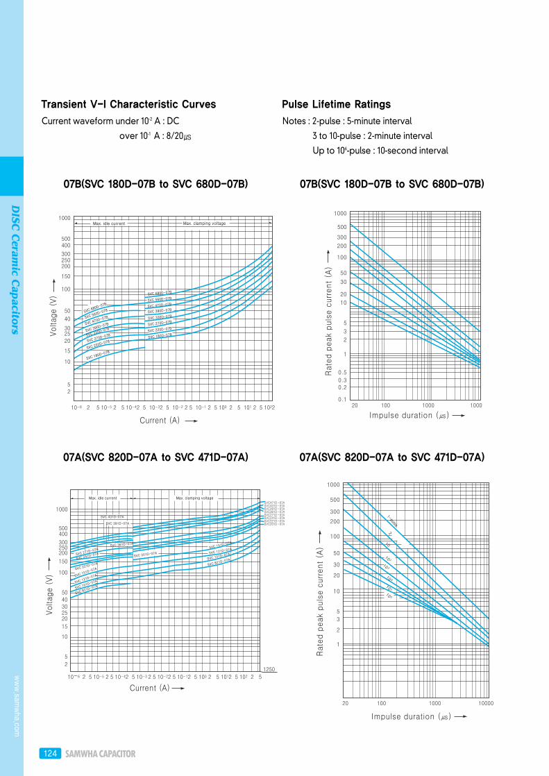
Transient V-I Characteristic Curves
07B(SVC 180D-07B to SVC 680D-07B)
Current waveform under 10-2 A : DC
over 10-1 A : 8/20
Pulse Lifetime Ratings
07B(SVC 180D-07B to SVC 680D-07B)
Notes : 2-pulse : 5-minute interval
3 to 10-pulse : 2-minute interval
Up to 106-pulse : 10-second interval
07A(SVC 820D-07A to SVC 471D-07A) 07A(SVC 820D-07A to SVC 471D-07A)
www.sam
wha.com
DISC
Ceram
ic Capacitors
DISC Ceramic Capacitors 125
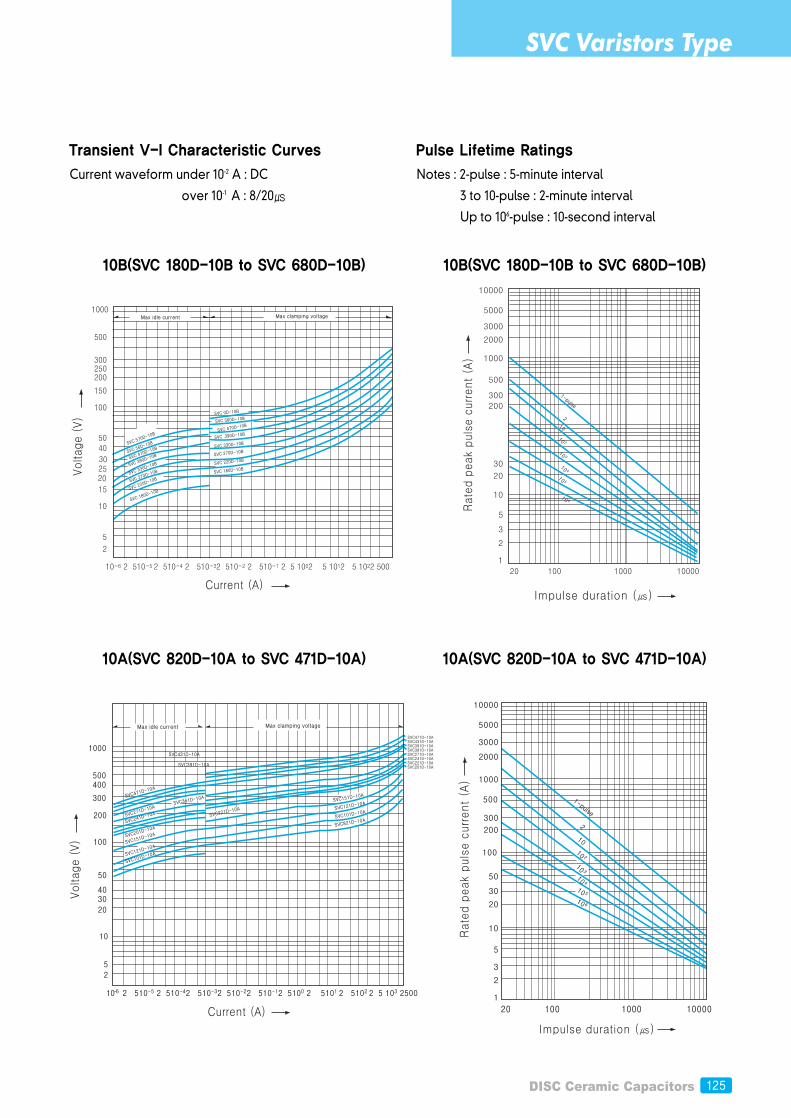
Transient V-I Characteristic Curves
10B(SVC 180D-10B to SVC 680D-10B)
Current waveform under 10-2 A : DC
over 10-1 A : 8/20
Max clamping voltageMax idle current
SVC 180D-10B
SVC 180D
-10B
Pulse Lifetime Ratings
10B(SVC 180D-10B to SVC 680D-10B)
Notes : 2-pulse : 5-minute interval
3 to 10-pulse : 2-minute interval
Up to 106-pulse : 10-second interval
10A(SVC 820D-10A to SVC 471D-10A) 10A(SVC 820D-10A to SVC 471D-10A)
SVC Varistors Type
126
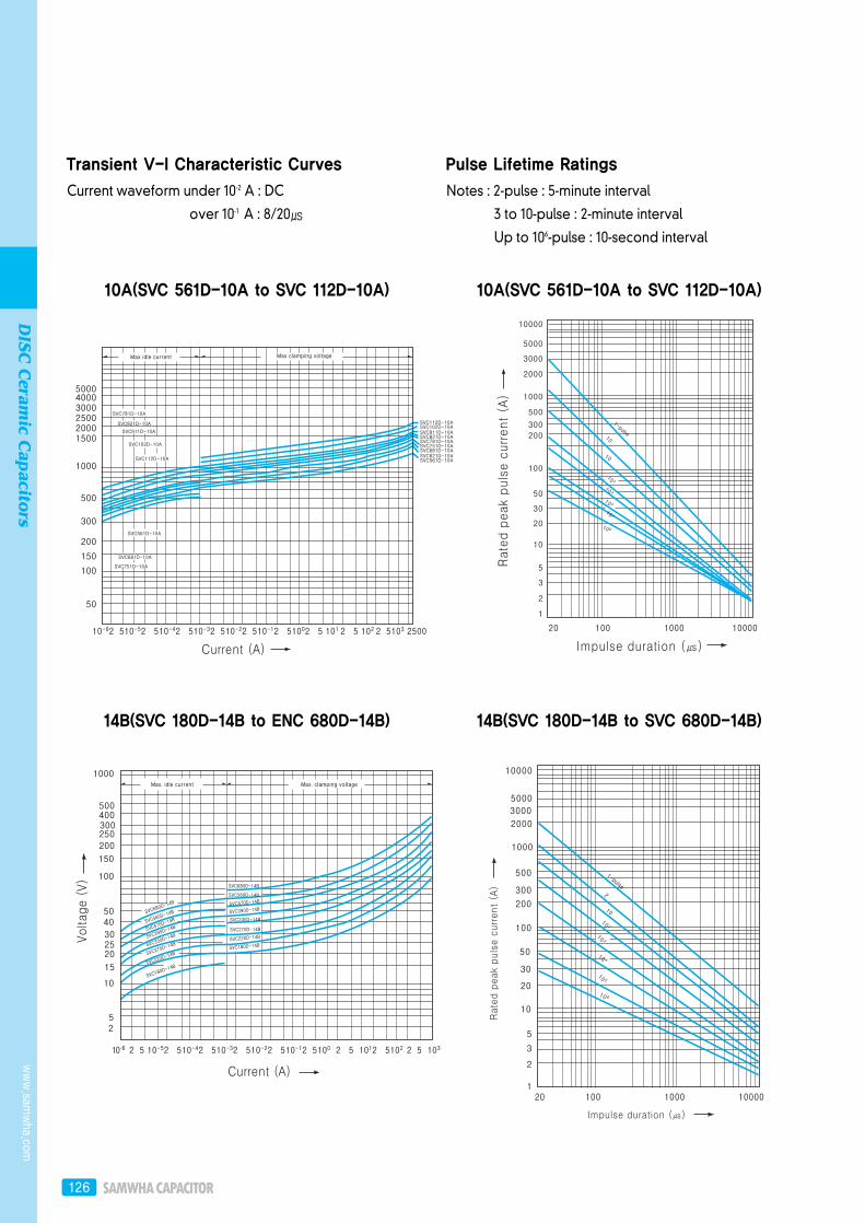
Transient V-I Characteristic Curves
10A(SVC 561D-10A to SVC 112D-10A)
Current waveform under 10-2 A : DC
over 10-1 A : 8/20
Pulse Lifetime Ratings
10A(SVC 561D-10A to SVC 112D-10A)
Notes : 2-pulse : 5-minute interval
3 to 10-pulse : 2-minute interval
Up to 106-pulse : 10-second interval
1-pulse
14B(SVC 180D-14B to ENC 680D-14B) 14B(SVC 180D-14B to SVC 680D-14B)
www.sam
wha.com
DISC
Ceram
ic Capacitors
DISC Ceramic Capacitors 127
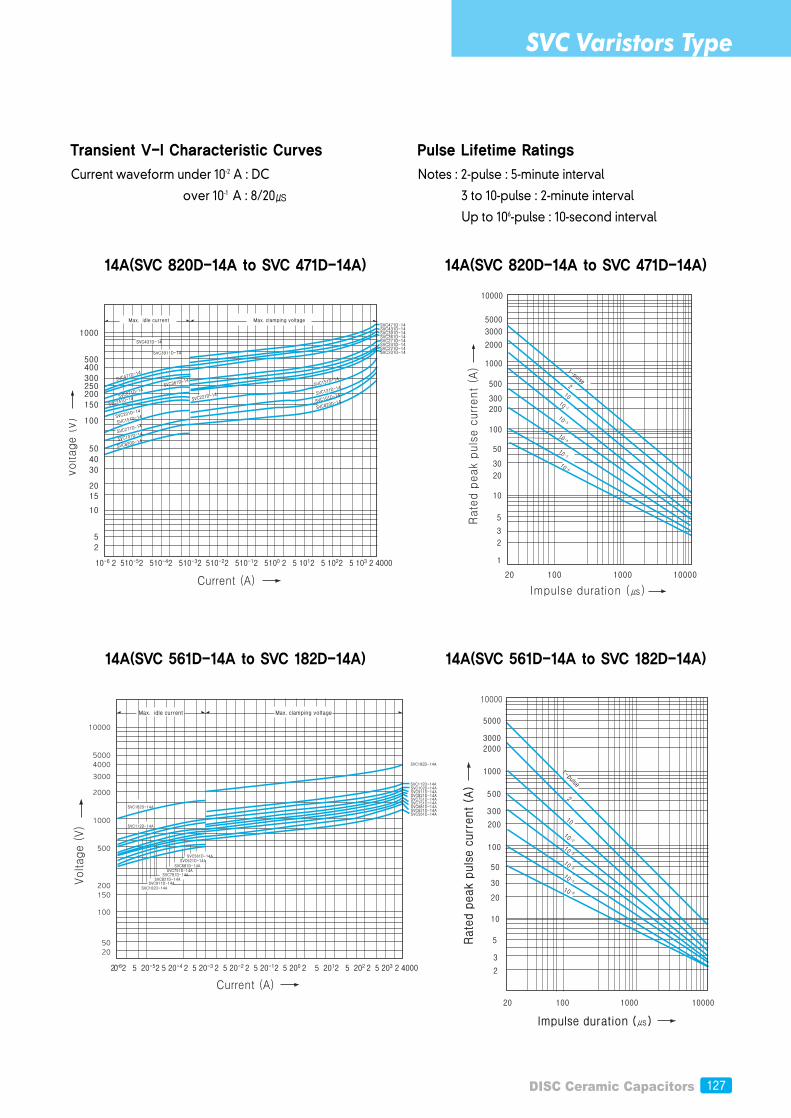
Transient V-I Characteristic Curves
14A(SVC 820D-14A to SVC 471D-14A)
Current waveform under 10-2 A : DC
over 10-1 A : 8/20
Pulse Lifetime Ratings
14A(SVC 820D-14A to SVC 471D-14A)
Notes : 2-pulse : 5-minute interval
3 to 10-pulse : 2-minute interval
Up to 106-pulse : 10-second interval
14A(SVC 561D-14A to SVC 182D-14A) 14A(SVC 561D-14A to SVC 182D-14A)
SVC Varistors Type
128
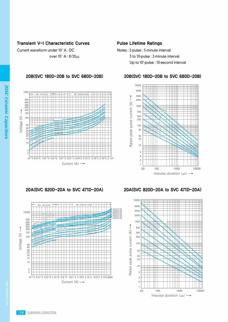
Transient V-I Characteristic Curves
20B(SVC 180D-20B to SVC 680D-20B)
Current waveform under 10-2 A : DC
over 10-1 A : 8/20
Pulse Lifetime Ratings
20B(SVC 180D-20B to SVC 680D-20B)
Notes : 2-pulse : 5-minute interval
3 to 10-pulse : 2-minute interval
Up to 106-pulse : 10-second interval
20A(SVC 820D-20A to SVC 471D-20A) 20A(SVC 820D-20A to SVC 471D-20A)
www.sam
wha.com
DISC
Ceram
ic Capacitors
DISC Ceramic Capacitors 129
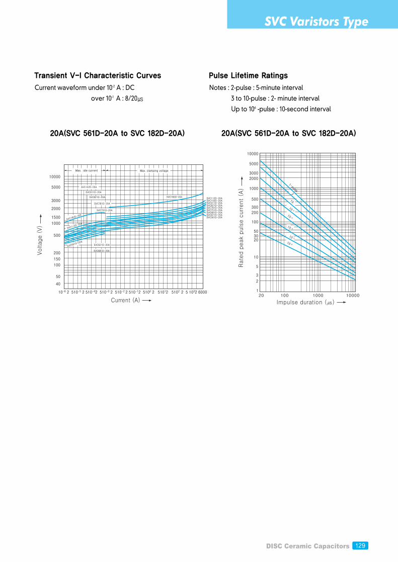
Transient V-I Characteristic Curves
20A(SVC 561D-20A to SVC 182D-20A)
Current waveform under 10-2 A : DC
over 10-1 A : 8/20
Pulse Lifetime Ratings
20A(SVC 561D-20A to SVC 182D-20A)
Notes : 2-pulse : 5-minute interval
3 to 10-pulse : 2- minute interval
Up to 106 -pulse : 10-second interval
SVC Varistors Type
130
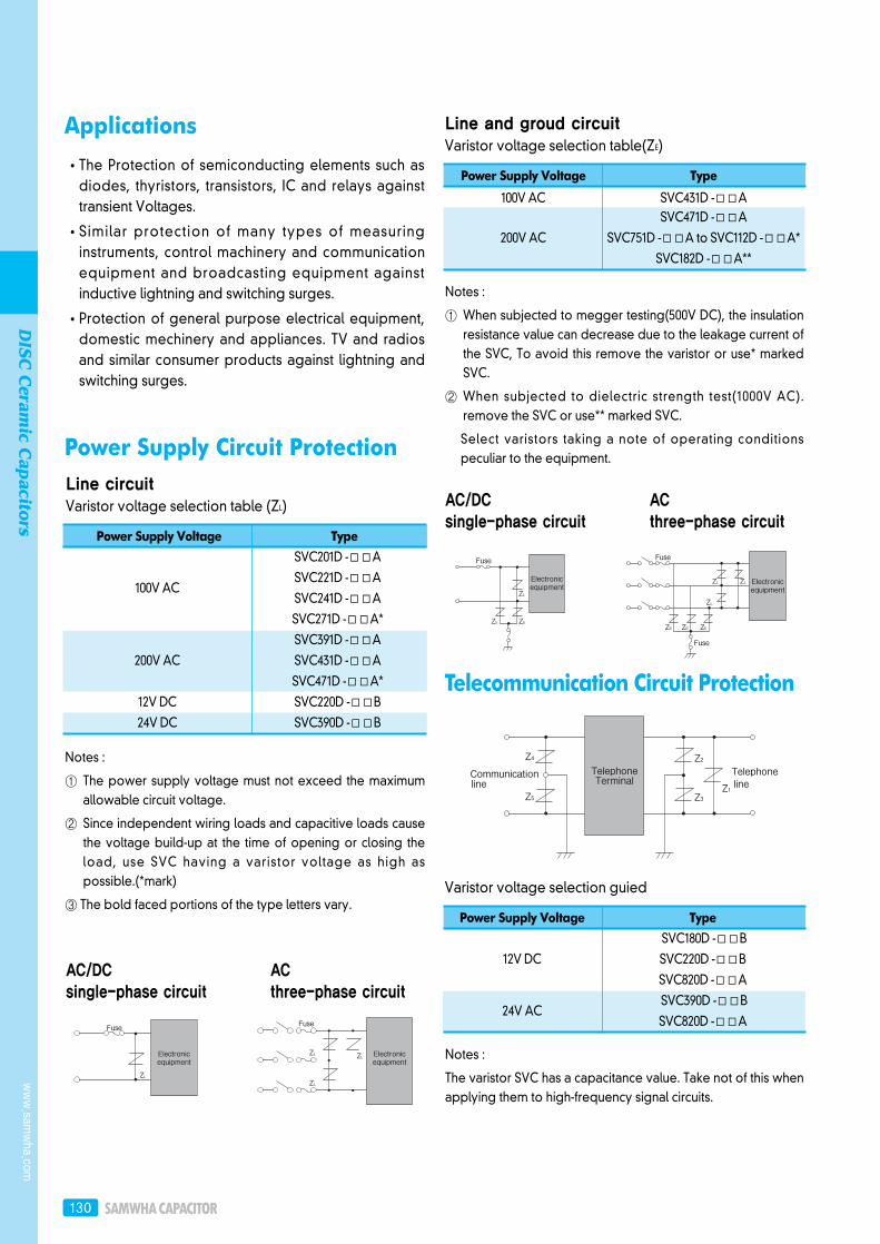
Applications
Power Supply Circuit Protection
The Protection of semiconducting elements such asdiodes, thyristors, transistors, IC and relays againsttransient Voltages.
Similar protection of many types of measuringinstruments, control machinery and communicationequipment and broadcasting equipment againstinductive lightning and switching surges.
Protection of general purpose electrical equipment,domestic mechinery and appliances. TV and radiosand similar consumer products against lightning andswitching surges.
Line circuitVaristor voltage selection table (ZL)
Power Supply Voltage Type
SVC201D -A
100V AC SVC221D -A
SVC241D -A
SVC271D -A*
SVC391D -A
200V AC SVC431D -A
SVC471D -A*
12V DC SVC220D -B
24V DC SVC390D -B
Line and groud circuitVaristor voltage selection table(ZE)
Power Supply Voltage Type
100V AC SVC431D -ASVC471D -A
200V AC SVC751D -A to SVC112D -A*
SVC182D -A**
Power Supply Voltage Type
SVC180D -B
12V DC SVC220D -B
SVC820D -A
24V ACSVC390D -B
SVC820D -A
Notes :
① The power supply voltage must not exceed the maximumallowable circuit voltage.
② Since independent wiring loads and capacitive loads causethe voltage build-up at the time of opening or closing theload, use SVC having a varistor voltage as high aspossible.(*mark)
③ The bold faced portions of the type letters vary.
AC/DC single-phase circuit
AC three-phase circuit
Notes :
① When subjected to megger testing(500V DC), the insulationresistance value can decrease due to the leakage current ofthe SVC, To avoid this remove the varistor or use* markedSVC.
② When subjected to dielectric strength test(1000V AC).remove the SVC or use** marked SVC.
Select varistors taking a note of operating conditionspeculiar to the equipment.
Notes :
The varistor SVC has a capacitance value. Take not of this whenapplying them to high-frequency signal circuits.
AC/DC single-phase circuit
AC three-phase circuit
Telecommunication Circuit Protection
Varistor voltage selection guied
www.sam
wha.com
DISC
Ceram
ic Capacitors
DISC Ceramic Capacitors 131
Power Supply Voltage Type
12V DC SVC220D -B
24V DC SVC390D -B
100V DC SVC151D -A
SVC201D -A
100V AC SVC221D -A
SVC241D -A
SVC271D -A
Notes :
① The power supply voltage must not exceed the maximumallowable circuit voltage of the SVC
② Pay due attention to the surge energy generated by theload.
③ Select SVC referring to the pulse lifetime rating.
④ To further reduce the tendency of sparking across thecontacts connect a capacitors parallel with the SVC. This willalso protect the equipment from electromagnetic wavejamming.
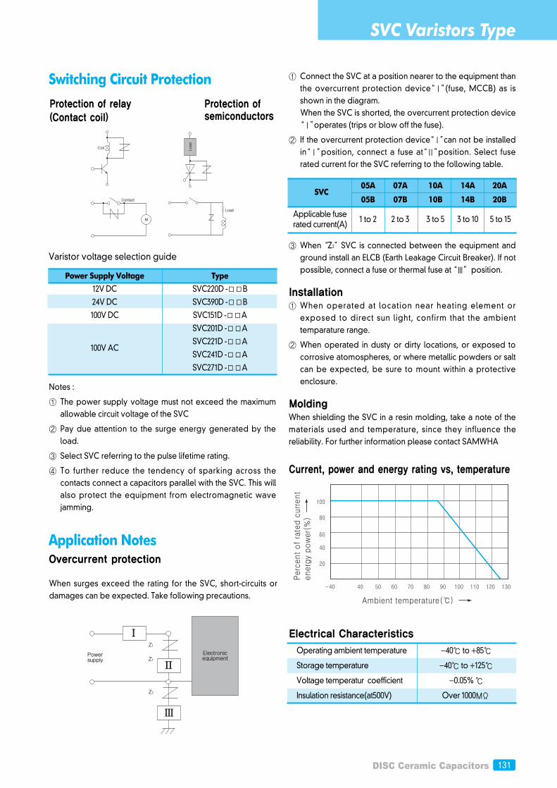
① Connect the SVC at a position nearer to the equipment thanthe overcurrent protection device“Ⅰ”(fuse, MCCB) as isshown in the diagram.When the SVC is shorted, the overcurrent protection device“Ⅰ”operates (trips or blow off the fuse).
② If the overcurrent protection device“Ⅰ”can not be installedin“Ⅰ”position, connect a fuse at“Ⅱ”position. Select fuserated current for the SVC referring to the following table.
③ When “Z2”SVC is connected between the equipment andground install an ELCB (Earth Leakage Circuit Breaker). If notpossible, connect a fuse or thermal fuse at “Ⅲ”position.
Installation① When operated at location near heating element or
exposed to direct sun light, confirm that the ambienttemparature range.
② When operated in dusty or dirty locations, or exposed tocorrosive atomospheres, or where metallic powders or saltcan be expected, be sure to mount within a protectiveenclosure.
MoldingWhen shielding the SVC in a resin molding, take a note of thematerials used and temperature, since they influence thereliability. For further information please contact SAMWHA
Current, power and energy rating vs, temperature
Electrical Characteristics
Switching Circuit Protection
Application NotesOvercurrent protection
Varistor voltage selection guide
Protection of relay(Contact coil)
Protection ofsemiconductors
When surges exceed the rating for the SVC, short-circuits ordamages can be expected. Take following precautions.
SVC 05A 07A 10A 14A 20A
05B 07B 10B 14B 20B
Applicable fuse 1 to 2 2 to 3 3 to 5 3 to 10 5 to 15
rated current(A)
Operating ambient temperature -40 to +85
Storage temperature -40 to +125
Voltage temperatur coefficient -0.05%
Insulation resistance(at500V) Over 1000MΩ
SVC Varistors Type
132
Standard Content Applicable SVC series File No.
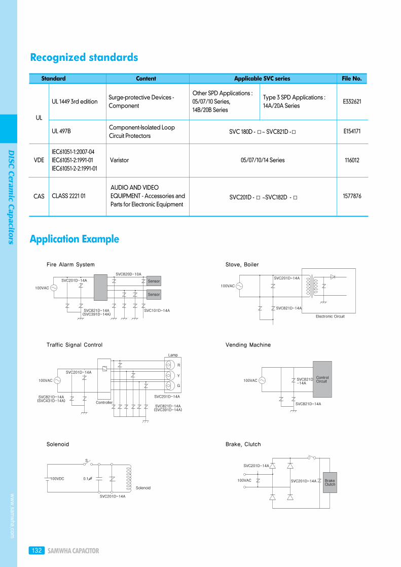
Recognized standards
Application Example
UL
CAS
VDE
Fire Alarm System
Traffic Signal Control
Solenoid
Stove, Boiler
Vending Machine
Brake, Clutch
www.sam
wha.com
DISC
Ceram
ic Capacitors
SVC201D - ~SVC182D -
UL 1449 3rd edition
UL 497B
IEC61051-1:2007-04IEC61051-2:1991-01IEC61051-2-2:1991-01
CLASS 2221 01AUDIO AND VIDEOEQUIPMENT - Accessories andParts for Electronic Equipment
Varistor
Component-Isolated LoopCircuit Protectors
SVC 180D - ~ SVC821D -
05/07/10/14 Series
Surge-protective Devices -Component
Other SPD Applications :05/07/10 Series, 14B/20B Series
Type 3 SPD Applications :14A/20A Series
E332621
E154171
116012
1577876
DISC Ceramic Capacitors 133
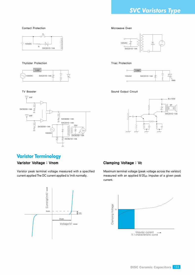
Varistor TerminologyVaristor Voltage : Vnom
Varistor peak terminal voltage measured with a specifiedcurrent applied The DC current applied is 1mA normally.
Clamping Voltage : Vc
Maximum terminal voltage (peak voltage across the varistor)measured with an applied 8/20 impulse of a given peakcurrent.
Contect Protection
Thytister Protection
TV Booster
Microwave Oven
Triac Protection
Sound Output Circuit
SVC Varistors Type
134
CapacitanceTypical values measured at a test frequency of 1kHz
Rated peak transient current : itmMaximum peak current through the varistor with line voltageapplied.
The maximum peak current with in the varistor voltage changeratio of ±10% with the standard 8/20 impulse current appliedtwo times at 5 minute interval.
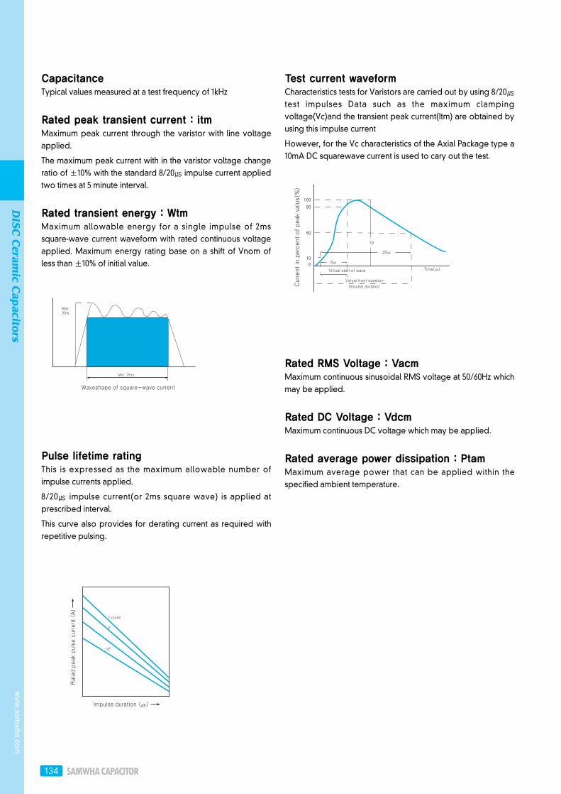
Rated transient energy : WtmMaximum allowable energy for a single impulse of 2mssquare-wave current waveform with rated continuous voltageapplied. Maximum energy rating base on a shift of Vnom ofless than ±10% of initial value.
Pulse lifetime ratingThis is expressed as the maximum allowable number ofimpulse currents applied.
8/20 impulse current(or 2ms square wave) is applied atprescribed interval.
This curve also provides for derating current as required withrepetitive pulsing.
Test current waveformCharacteristics tests for Varistors are carried out by using 8/20test impulses Data such as the maximum clampingvoltage(Vc)and the transient peak current(Itm) are obtained byusing this impulse current
However, for the Vc characteristics of the Axial Package type a10mA DC squarewave current is used to cary out the test.
Rated RMS Voltage : VacmMaximum continuous sinusoidal RMS voltage at 50/60Hz whichmay be applied.
Rated DC Voltage : VdcmMaximum continuous DC voltage which may be applied.
Rated average power dissipation : PtamMaximum average power that can be applied within thespecified ambient temperature.
www.sam
wha.com
DISC
Ceram
ic Capacitors