surface repair concrete repair using form-and- … · form or by any means, including the making of...
TRANSCRIPT
American Concrete Institute®
Advancing concrete knowledge
ACI RAP Bulletin 4
Surface Repair Using Form-and-Pour Techniques (ACI RAP-4) 1
Surface RepairUsing Form-and-Pour Techniques
FIELD GUIDE TOCONCRETE REPAIR
APPLICATION PROCEDURES

2 Repair Application Procedures Bulletin

Surface Repair Using Form-and-Pour Techniques (ACI RAP-4) 3
Field Guide to Concrete Repair Application Procedures
Surface Repair Using Form-and-Pour Techniques
Reported by ACI Committee E706
ACI RAP Bulletin 4(Reapproved 2009)
J. Christopher Ball H. Peter Golter John S. Lund George I. Taylor
Floyd E. Dimmick, Sr. Bob Joyce Richard Montani Patrick M. Watson
Peter H. Emmons* Kenneth M. Lozen Jay H. Paul David W. Whitmore
Timothy R. W. Gillespie
*Primary author.
Brian F. KeaneChair
ACI Repair Application Procedure 4.Copyright © 2003, American Concrete Institute.All rights reserved including rights of reproduction and use in any
form or by any means, including the making of copies by any photo pro-cess, or by electronic or mechanical device, printed, written, or oral, orrecording for sound or visual reproduction or for use in any knowledgeretrieval system or device, unless permission in writing is obtained fromthe copyright proprietors. Printed in the United States of America.
The Institute is not responsible for the statements oropinions in its publications. Institute publications arenot able nor intended to supplant individual training,responsibility or judgment of the user, or the supplier ofthe information provided.
Structural DisclaimerThis document is intended as a voluntary field guide forthe Owner, design professional, and concrete repair con-tractor. It is not intended to relieve the user of this guideof responsibility for a proper condition assessment andstructural evaluation of existing conditions, and for thespecification of concrete repair methods, materials, orpractices by an experienced engineer/designer.
It is the responsibility of the user of this document toestablish health and safety practices appropriate to the specificcircumstances involved with its use. ACI does not make anyrepresentations with regard to health and safety issues and the useof this document. The user must determine the applicability ofall regulatory limitations before applying the document andmust comply with all applicable laws and regulations,including but not limited to, United States OccupationalSafety and Health Administration (OSHA) health andsafety standards.
4 Repair Application Procedures Bulletin
IntroductionThe form-and-pour placement technique is a multistep
process of preparation, formwork construction, and placementof repair materials. Repair materials are placed in the cavitybetween the formwork and the prepared substrate withbuckets, pumps, chutes, or buggies. The form-and-pourtechnique allows the use of many different castable repairmaterials. Placeability is the primary consideration materialselection. Depending on the consistency of the repairmaterial, consolidation is accomplished by vibration, rodding,or when the material has extremely high slump (self consoli-dating), no additional steps may be required.
What is the purpose of this repair?The primary purpose of this type of repair is to restore the
structural integrity, or concrete cover requirements, or both,for the damaged element.
When do I use this technique?This technique is commonly used on vertical surfaces such
as walls, columns, and other combinations such as beamsides and bottoms. When used to repair slab soffits, therepair material is typically placed through holes or openingscut through the slab. Adhesive bonding agents or grouts arenot commonly used with this technique. A trial installation ishighly recommended for each project, to verify the prepara-tion, material, and placement technique using quality-controlprocedures outlined at the end of this document.
The form-and-pour technique offers many advantages:
• Many different types of repair materials can be used;
• Repair material can be placed around reinforcing steel;and
• Formwork protects against early-age drying thatpromotes cracking.
The primary limitation of the form-and-pour technique isthat formwork installation makes it more labor-intensivethan alternative placement methods such as shotcrete or handapplication (see Fig. 1).
How do I prepare the surface?Regardless of the repair method, surface preparation is
essentially the same. Concrete is removed until soundconcrete is located. Exposed bars are undercut, and surfacesare cleaned with high-pressure water, or are abrasivelyblasted. With form-and-pour techniques, it is important tounderstand how the existing surfaces will permit the repairmaterial to penetrate and flow. On partial-depth verticalrepairs, the upper edges of vertical surfaces should betrimmed to eliminate potential pockets of entrapped air andpromote complete filling from the location of the chute.Refer to page 5 for step-by-step preparation procedures.
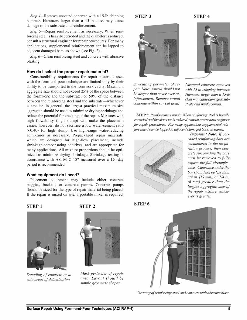
Step 1—Sound the concrete to locate areas of delamina-tion.
Step 2—Mark the perimeter of the repair area. Layoutshould be simple square or rectangular shapes.
Step 3—Sawcut the perimeter of the repair. Note: sawcutshould not be deeper than the cover over reinforcement.
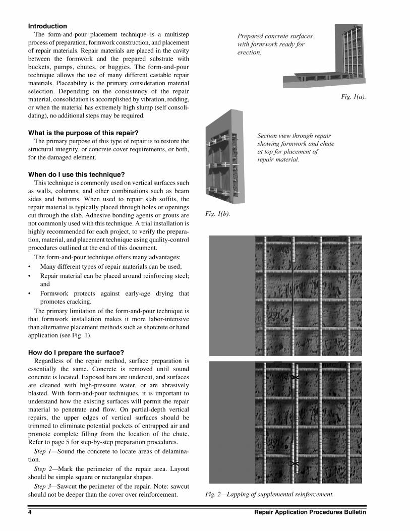
Fig. 1(a).
Fig. 1(b).
Fig. 2—Lapping of supplemental reinforcement.
Surface Repair Using Form-and-Pour Techniques (ACI RAP-4) 5
Step 4—Remove unsound concrete with a 15-lb chippinghammer. Hammers larger than a 15-lb class may causedamage to the substrate and reinforcement.
Step 5—Repair reinforcement as necessary. When rein-forcing steel is heavily corroded and the diameter is reduced,consult a structural engineer for repair procedures. For manyapplications, supplemental reinforcement can be lapped toadjacent damaged bars, as shown (see Fig. 2).
Step 6—Clean reinforcing steel and concrete with abrasiveblasting.
How do I select the proper repair material?Constructibility requirements for repair materials used
with the form-and-pour technique are limited only by theirability to be transported to the formwork cavity. Maximumaggregate size should not exceed 25% of the space betweenthe formwork and the substrate, or 50% of the distancebetween the reinforcing steel and the substrate—whicheveris smaller. In general, the largest practical maximum sizeaggregate should be used to minimize drying-shrinkage andreduce the potential for cracking of the repair. Mixtures withhigh flowability (high slump) will make the placementeasier; however, do not sacrifice a low water-cement ratio(<0.40) for high slump. Use high-range water-reducingadmixtures as necessary. Prepackaged repair materials,which are designed for high-flow placement, includeshrinkage-compensating additives, and are appropriate formany applications. All mixture proportions should be opti-mized to minimize drying shrinkage. Shrinkage testing inaccordance with ASTM C 157 measured over a 120-dayperiod is recommended.
What equipment do I need?Placement equipment may include either concrete
buggies, buckets, or concrete pumps. Concrete pumpsshould be sized for the type of repair material being placed.If the repair is mixed on site, a portable mixer is required.
6 Repair Application Procedures Bulletin
Check with the manufacturer of the product to determine therecommended type of mixer.
What are the safety considerations?Job site safety practices include, but are not limited to, the
following where applicable:
• Material Safety Data Sheets (MSDS) available;
• Protective clothing worn by workers handling orexposed to hazardous materials;
• Use of protective eyewear during pumping and place-ment of repair materials;
• Availability of eye wash facilities; and• Use of respirators and ear protection during demolition.
It is the responsibility of the user of this document toestablish health and safety practices appropriate to thespecific circumstances involved with its use. ACI does notmake any representations with regard to health and safetyissues and the use of this document. The user must determinethe applicability of all regulatory limitations before applying
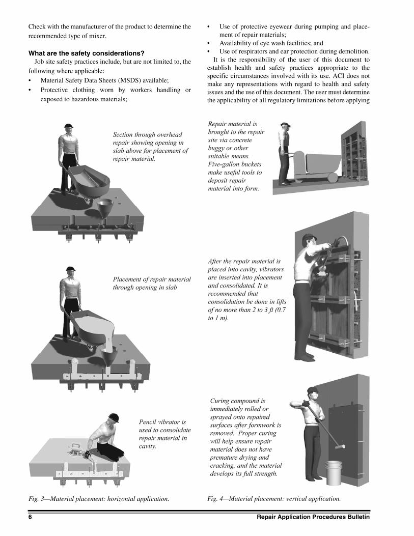
Fig. 3—Material placement: horizontal application. Fig. 4—Material placement: vertical application.

Surface Repair Using Form-and-Pour Techniques (ACI RAP-4) 7
the document and must comply with all applicable laws andregulations, including but not limited to, United States Occu-pational Safety and Health Administration (OSHA) healthand safety standards.
Preconstruction meetingPrior to proceeding with the repair, a preconstruction
meeting is recommended. The meeting should include repre-sentatives from all participating parties (owner, engineer,contractor, materials manufacturer, etc.), and specificallyaddress the parameters, means, methods, and materialsnecessary to achieve the repair objectives.
Repair procedureFormwork construction—Formwork must accommodate
the mass and pressure of the repair material. Design of theforms should follow standard practice for cast-in-placeconcrete construction. Formwork is best attached directly tothe concrete surface with expansion anchors or rock anchorsdesigned for coil rod. In cases of repair of slab soffits (under-side), scaffold frames or shoring posts can be used to supportthe formwork tight against the concrete surfaces. Whenexpansion/rock anchors are used, ensure anchors are firmlyset in place to prevent slippage under load. Preloading ofrock anchors with coil rod can be accomplished with acenter-hole jack applying loads to the coil rod with a stand-off. Forms should be constructed to fit tightly againstexisting surfaces. Preformed gaskets or cast-in-place foamwork well on difficult-to-match surfaces. Placement open-
ings or chutes are required to place the repair material behindvertical forms. Chutes should be constructed to permit devel-opment of a hydraulic head above the prepared upper edgesof the concrete surface. This will provide for repair materialsupply into these upper horizontal zones after concrete isconsolidated. For large, vertical surfaces exceeding 10 ft (3m) in height, multiple lifts should be considered to reducefree-fall segregation and excessive formwork pressures.Formwork for overhead surfaces does not require openingsfor placement of repair materials. Generally, placementoccurs through openings in the slab from above (see Fig. 3).
Material placement—Prior to placement of the repairmaterial, moisture conditioning of the prepared surfaceshould provide for saturated-surface dry conditions. It isimportant not to overwet the surface. Saturated surfaces willprevent proper bonding because the surface pores areclogged with water, unable to absorb the repair material.Mixed repair material is brought to the formed area via what-ever transport technique is appropriate for the situation (seeFig. 4). This may include buckets, pumpline, buggies, orwheelbarrows. For vertical surfaces, material is placed intothe chute or opening. External or internal vibration is a mustfor almost all mixture consistencies. Some self-levelingrepair materials, also known as self-consolidating, can beplaced without vibration. When the cavity is filled, extra careshould be taken to ensure that the uppermost surfaces arefilled adjacent to the chute or opening where placementoccurs. Rodding or tamping can ensure proper filling. Form-work should be left in place for the prescribed curing period.
Fig. 5—Test procedure.

8 Repair Application Procedures Bulletin
After stripping of formwork, any spaces not filled should betrimmed, cleaned, and dry-packed. Placement of amembrane curing compound is recommended immediatelyafter removal of formwork.
How do I check the repairs?After stripping of forms, various tests can be performed to
confirm that the repair material was thoroughly consolidatedand that adequate bond to the substrate was achieved. Auniaxial bond test can be performed by drilling through therepair into the substrate. A bonded plate attached to the coreis pulled until rupture occurs. The location of the failureshould be reviewed. Bond values typically exceed 100 psi(0.7 MPa) and, in most cases, exceed 150 psi (1 MPa). Thesetests are performed in accordance with ACI 503R Appendix(see Fig. 5).
The complete repair area should also be hammer-sounded to locate voids and delaminations within the top
6 in. (150 mm). Any hollow sounds may indicate poorbond or voids.
Sources for additional information1. “Guide for Surface Preparation for the Repair of Deterio-
rated Concrete Resulting from Reinforcing Steel Corrosion,”No. 03730, International Concrete Repair Institute, 1995, 5 pp.
2. “Guide for Selecting and Specifying Concrete RepairMaterials,” No. 03733, International Concrete RepairInstitute, 1996, 34 pp.
3. ACI Committee 347, “Guide to Formwork for Concrete(ACI 347-01),” American Concrete Institute, FarmingtonHills, Mich., 2001, 32 pp.
4. ACI Committee 546, “Concrete Repair Guide (ACI546R-96),” American Concrete Institute, Farmington Hills,Mich., 1996, 41 pp.
5. ACI Committee 503, “Use of Epoxy Compoundswith Concrete (503R-93),” American Concrete Institute,Farmington Hills, Mich., 1998, 28 pp.