surface mount technology you can work with it - …n5dux.com/ham/files/pdf/smt you can work...
TRANSCRIPT
April 1999 33
AsI look through the various elec-tronic manufacturing compa-nies’ product datasheets, threethings strike me. First, the large
number of available ICs that perform func-tions formerly requiring several ICs. Second,the continuing shift to lower-power require-ments, smaller size and usability at higheroperating frequencies. Finally, the increas-ing number of new products are availableonly in surface-mount packages. It all fitstogether: Products today are smaller andmore energy efficient. Look at modern H-Ts,cell phones, GPS equipment, laptop comput-ers, microwave ovens, intelligent electronicovens, TV remote controls and pocket calcu-lators: One thing they have in common istheir use of surface-mount (SM) ICs.
On the other hand, when I look at Ama-teur Radio projects, I see continued use ofmany discrete components and bulky DIPICs that perform limited functions. Recently,I saw a voltage-controller project based onthe use of transistors and relays! Frankly, itbothers me that there seems to be a growingdivergence between the technology used byindustry and that used by hams. The MaximEngineering Journal Vol. 29, for instance,showcases such new ICs as an image-rejectRF transceiver, a low-phase-noise RF oscil-lator that replaces VCO modules, a 3 V, 1 W,900 MHz RF power transistor, a direct-con-version down-converter IC that replaces anIF mixer, an IF LO and SAW filter, and alow-voltage IF transceiver that includes theFM limiter and RSSI. All these multifunc-tion ICs are available only in SM packages!I think hams are being left behind becausethey feel that SMT (surface-mount technol-ogy) is something they can’t handle.
Since I built my first SM project two yearsago, I have assembled a dozen others. I findthat my skill levels have increased tremen-dously with practice, and I now routinelytackle projects I never thought possible justa year ago. Based on my experience, I knowthat amateurs can work with SMT. Perhaps
By Sam Ulbing, N4UAU
Surface MountTechnology—You Can Work with It!
1Notes appear on page 38.
Part 1—Start building yourprojects with surface-mountdevices! I’ll show you how!
when we show this ability, there will be moretruly state-of-the-art projects in the amateurpublications. How about a very small 2 meterrig, or a 900 MHz personal communicator?The ICs already exist and we need to adaptthem to ham use. First however, it is neces-sary to develop a few basic building skills.This article series will help you develop those
skills by showing what I have learned andpresenting several useful and easy-to-buildprojects. Once you have built these, you willbe able to handle most of the SM ICs I haveseen used in the industry.
Nothing NewThe concept of surface mounting parts is
not new to Amateur Radio. In a September1979 QST article,1 Doug DeMaw, W1FB(SK), discusses a quick and easy circuit-board design that was basically SMT; Dougalso proposed a universal PC-board layoutfor this kind of construction. You may thinkthat there will always be DIP versions of allthe SM ICs so engineers can experiment, buteven today, many manufacturers are makingevaluation boards available to designers sothey can test the part using SM devices! Isuspect it’s cheaper for them to sell evalua-tion boards than to set up a production lineto make a very limited number of DIP ICswhen their real volume is in SM devices.
Some of the advantages of building withSM devices include:• Smaller projects: I built a time-out switch
that fits on a PC board one-sixth the sizeof a postage stamp! I was able to put thecircuit into the battery compartment of avoltmeter I had so it could automaticallypower itself down.2
• Many SM versions of devices outperformthe original DIP versions. Lower operat-ing voltages and quiescent currents in themicroampere range offer more efficientoperation.
• Most RF projects require the use of shortsignal leads. SM capacitors are often rec-ommended for use as bypass capacitorsbecause they can be placed close to an ICand exhibit very low lead inductance.Nearly all VHF projects benefit from theuse of SM devices.
• Once you’ve had some experience in work-ing with SM devices, you’ll feel more con-
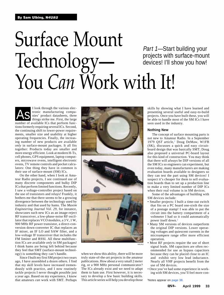
N4UAU
34 April 1999
fident about repairing your own gear.• Making a PC board for SM devices is easier
than for through-hole parts because nocomponent-mounting holes need to bedrilled.
• Many new SM ICs have entire modules builtinto them making it much easier to build acomplex circuit than with older ICs.3
Equipment NeededMany people think you need lots of ex-
pensive equipment to work with SM de-vices.4 Not so! You don’t need an eagle’seyesight, either! My optometrist describesmy eyesight as “moderately near-sighted,needing bifocals (21/2 diopters).” My wifethinks I am as blind as a bat.• A fundamental piece of equipment for SM
work is an illuminated magnifying glass. Iuse an inexpensive one with a 5-inch-di-ameter lens (see the accompanying trio oftools photographs). I use the magnifier forall my soldering work, not just for SM use.Such magnifiers are widely available (seethe sidebar “Manufacturers and Distribu-tors of SMT Equipment and Parts”) andrange in price from about $25 to severalhundred dollars. Most offer a 3× magnifi-cation and have a built-in circular light.
• A low-power soldering iron is necessary;one that is temperature-controlled (such asthe Weller WCC100) practically elimi-nates the possibility of overheating a part.Use a soldering iron with a grounded tip asmost SM parts are CMOS devices and aresubject to possible ESD (static) failure. Ihave found the Weller 1/16-inch (EJA)screwdriver tip works well. I used to usean ETJ with its finer conical tip, but it doesnot seem to transfer the heat as well as thescrewdriver tip.
• Use of thin (0.020-inch diameter) rosin-core solder is preferred because the partsare so small that regular 0.031-inch diam-eter solder will flood a solder pad andcause bridging.
• A wet sponge for cleaning the soldering-iron tip.
• A flux pen comes in handy for applyingjust a little flux at a needed spot. I findthat RadioShack’s flux is too sticky andit leaves a messy residue. The CircuitWorks CW8200 flux pen with a type Rflux is much cleaner.
• Good desoldering braid is necessary to re-move excess solder if you get too much ona pad. Chem-Wik Lite 0.100-inch wideworks well.
• ESD protective devices such as wrist strapsmay be necessary if you live in a dry areaand static is a problem. I live in humidFlorida, have never used these and havenot had a problem.
• Tweezers help pick up parts and positionthem. I find that a pair of nonmagnetic,stainless-steel drafting dividers work wellas tweezers. They have two very sharpneedle-like points that allow me to pick upthe smallest parts; and the parts seem lesslikely to slip from grasp perhaps becauseI use less force to hold them. The sharppoints are useful tools for marking the
PC-board copper foil before cutting outtraces (more on this later). The nonmag-netic property of stainless steel means thechip doesn’t get attracted to the dividers.
• If you want to make your own SM PCboards, I recommend using a DremelMototool (or something similar) and someultra-fine cutting wheels.
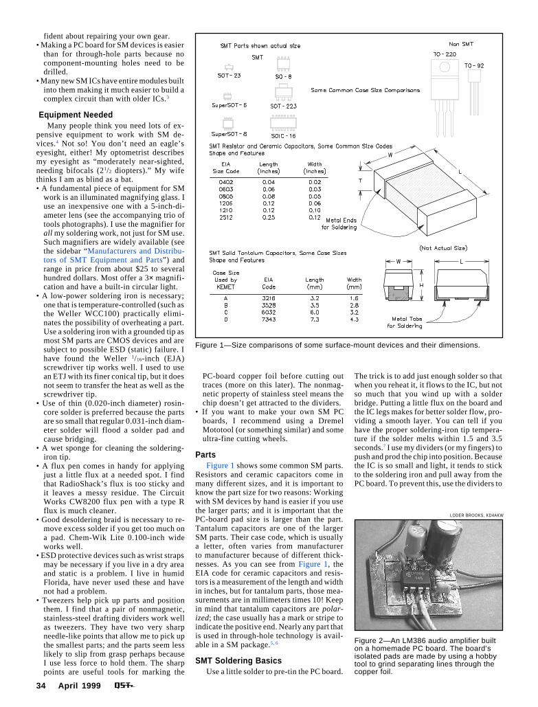
PartsFigure 1 shows some common SM parts.
Resistors and ceramic capacitors come inmany different sizes, and it is important toknow the part size for two reasons: Workingwith SM devices by hand is easier if you usethe larger parts; and it is important that thePC-board pad size is larger than the part.Tantalum capacitors are one of the largerSM parts. Their case code, which is usuallya letter, often varies from manufacturerto manufacturer because of different thick-nesses. As you can see from Figure 1, theEIA code for ceramic capacitors and resis-tors is a measurement of the length and widthin inches, but for tantalum parts, those mea-surements are in millimeters times 10! Keepin mind that tantalum capacitors are polar-ized; the case usually has a mark or stripe toindicate the positive end. Nearly any part thatis used in through-hole technology is avail-able in a SM package.5, 6
SMT Soldering BasicsUse a little solder to pre-tin the PC board.
The trick is to add just enough solder so thatwhen you reheat it, it flows to the IC, but notso much that you wind up with a solderbridge. Putting a little flux on the board andthe IC legs makes for better solder flow, pro-viding a smooth layer. You can tell if youhave the proper soldering-iron tip tempera-ture if the solder melts within 1.5 and 3.5seconds.7 I use my dividers (or my fingers) topush and prod the chip into position. Becausethe IC is so small and light, it tends to stickto the soldering iron and pull away from thePC board. To prevent this, use the dividers to
Figure 1—Size comparisons of some surface-mount devices and their dimensions.
Figure 2—An LM386 audio amplifier builton a homemade PC board. The board’sisolated pads are made by using a hobbytool to grind separating lines through thecopper foil.
LODER BROOKS, KD4AKW
April 1999 35
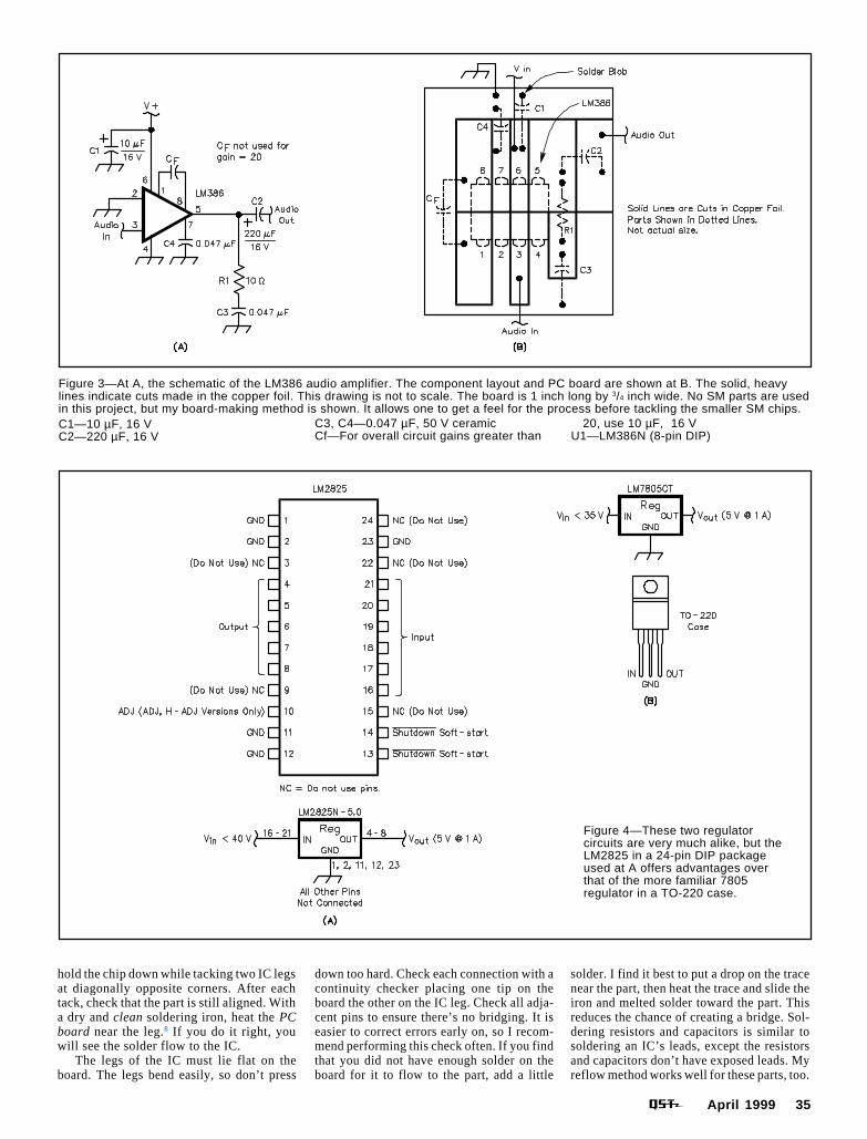
Figure 3—At A, the schematic of the LM386 audio amplifier. The component layout and PC board are shown at B. The solid, heavylines indicate cuts made in the copper foil. This drawing is not to scale. The board is 1 inch long by 3/4 inch wide. No SM parts are usedin this project, but my board-making method is shown. It allows one to get a feel for the process before tackling the smaller SM chips.C1—10 µF, 16 VC2—220 µF, 16 V
C3, C4—0.047 µF, 50 V ceramicCf—For overall circuit gains greater than
20, use 10 µF, 16 VU1—LM386N (8-pin DIP)
hold the chip down while tacking two IC legsat diagonally opposite corners. After eachtack, check that the part is still aligned. Witha dry and clean soldering iron, heat the PCboard near the leg.8 If you do it right, youwill see the solder flow to the IC.
The legs of the IC must lie flat on theboard. The legs bend easily, so don’t press
down too hard. Check each connection with acontinuity checker placing one tip on theboard the other on the IC leg. Check all adja-cent pins to ensure there’s no bridging. It iseasier to correct errors early on, so I recom-mend performing this check often. If you findthat you did not have enough solder on theboard for it to flow to the part, add a little
solder. I find it best to put a drop on the tracenear the part, then heat the trace and slide theiron and melted solder toward the part. Thisreduces the chance of creating a bridge. Sol-dering resistors and capacitors is similar tosoldering an IC’s leads, except the resistorsand capacitors don’t have exposed leads. Myreflow method works well for these parts, too.
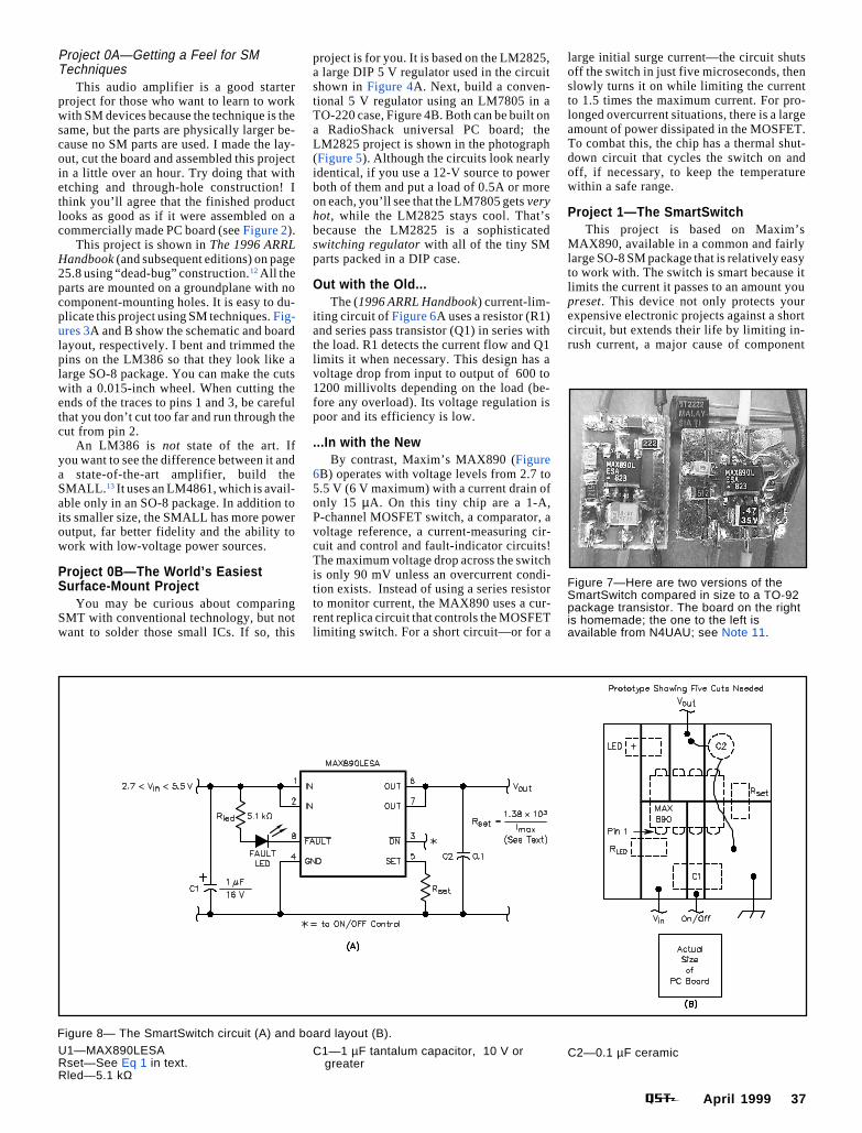
Figure 4—These two regulatorcircuits are very much alike, but theLM2825 in a 24-pin DIP packageused at A offers advantages overthat of the more familiar 7805regulator in a TO-220 case.

36 April 1999
Attaching wires that connect to points offthe board can be a bit of a challenge becauseeven #24 stranded wire is large in compari-son to the SM parts. First, make sure all thewire strands are close together, then pre-tinthe wire. Carefully place the wire on the pre-tinned pad and heat it with the soldering ironuntil the solder melts.9
Making a SM PC BoardIt is possible to etch SM PC boards just
like a conventional board, but I recall Doug(W1FB) DeMaw’s comment on etching: “Ifyou don’t mind a few brown stains here andthere on your garments, etching is one way tomake the board.” Evidently he, like I, didmind, and he proposed a strong-arm methodof using a hacksaw to cut square pads in theboard foil. Hacksaws are too large and widefor SM use; I use a Dremel Mototool and athin cutoff wheel. With these, I can cut a lineas narrow as 0.005 inch, which lets me buildwith most of the available SM ICs.
To make such a “PC” board, start bysketching a layout for it. Don’t worry aboutdrawing it to scale, but make the sketch largeenough to see what is happening. Normally,we think in terms of connections betweenparts because schematics show lines frompoint to point, representing the interconnect-ing wires. I find it is more useful to think interms of the spaces between the lines becauseI am removing copper material to separatetraces, not adding material to make traces.Where wires attach to the board, leave a largesurface because the wires are relatively large.When making cuts, it is easiest to do it usinga large piece of material that you can holdsecurely. Cut the board to size after you havecut all the traces.
Once I have the layout drawn, I hold theIC to the copper and used a fine-pointed tool(a 0.5 mm pencil or my dividers) to mark thelocation of the cuts on the PC board. I thenremove the IC and use my Dremel tool to cutthe copper along the marks. For critical cutsbetween an IC’s closely spaced leads, I makeone cut, then reposition the IC on the boardand verify that the remaining marks are still
Figure 5—LM2825 circuit is constructedon readily available RadioShack perfboard(RS 276-150 or similar). Photo showsoptional input filter capacitor and optionalsoft-start capacitor. Refer to the datasheetat the National Semiconductor Web pagefor suggested values for these optionalcomponents.
Figure 6—At A, a current-limiting circuit using older technology. Within the confinesof the tiny MAX890, (B) newer technology offers a 1-A, P-channel MOSFET switch,a comparator, a voltage reference, a current-measuring circuit, control and fault-indicator circuits!
correctly aligned. I do all this freehand. Us-ing an ultra-thin cutoff wheel, I find it is quiteeasy to cut in a straight line. At first, I useda fine cutting bit (#108), but that tip made awider cut and it was difficult to cut a straightline. Dedeco (see the sidebar “Manufactur-ers and Distributors of SMT Equipment andParts”), supplier of tools for jewelers anddentists, makes two ultra-thin wheels—0.009 and 0.005 inch. For the very smallICs—those in SOT23-5 and SuperSOT-8packages—I use a 0.005-inch wheel, other-wise the 0.009-inch wheel is ideal. Be care-ful when handling these wheels as they breakeasily. Also, don’t cut too deeply into theboard material. At the intersection of thecuts, take care not to cut too far. SometimesI cut close to an intersection, then use a razorblade to finish the job. A quick sandingdeburrs the cuts. Run through the cuts witha small screwdriver or pen knife to ensurethey are cleanly cut and without burrs.
Finally, use your ohmmeter to verify that theislands/pads aren’t connected.10
I recommend you make your own PCboards: They’re easier to produce thanthrough-hole boards, and you’ll then be ableto experiment with your own projects ratherthan waiting for others’ projects to comealong. You can use this method with SM ornon-SM projects.
The ProjectsAll the projects I’ll present are easy-to-
build beginner projects, yet each offers sig-nificant advantages over similar projectsbased on the old (DIP) technology. As youbuild each project, you’ll develop SM skillsand wind up with some useful gadgets. I havetried to arrange the projects by degree of skillrequired. For those who want to make theirown PC boards, I describe my layout. Ready-made PC boards are available for all of theseprojects except the first, Project 0A.11
April 1999 37
Project 0A—Getting a Feel for SMTechniques
This audio amplifier is a good starterproject for those who want to learn to workwith SM devices because the technique is thesame, but the parts are physically larger be-cause no SM parts are used. I made the lay-out, cut the board and assembled this projectin a little over an hour. Try doing that withetching and through-hole construction! Ithink you’ll agree that the finished productlooks as good as if it were assembled on acommercially made PC board (see Figure 2).
This project is shown in The 1996 ARRLHandbook (and subsequent editions) on page25.8 using “dead-bug” construction.12 All theparts are mounted on a groundplane with nocomponent-mounting holes. It is easy to du-plicate this project using SM techniques. Fig-ures 3A and B show the schematic and boardlayout, respectively. I bent and trimmed thepins on the LM386 so that they look like alarge SO-8 package. You can make the cutswith a 0.015-inch wheel. When cutting theends of the traces to pins 1 and 3, be carefulthat you don’t cut too far and run through thecut from pin 2.
An LM386 is not state of the art. Ifyou want to see the difference between it anda state-of-the-art amplifier, build theSMALL. 13 It uses an LM4861, which is avail-able only in an SO-8 package. In addition toits smaller size, the SMALL has more poweroutput, far better fidelity and the ability towork with low-voltage power sources.
Project 0B—The World’s EasiestSurface-Mount Project
You may be curious about comparingSMT with conventional technology, but notwant to solder those small ICs. If so, this
Figure 7—Here are two versions of theSmartSwitch compared in size to a TO-92package transistor. The board on the rightis homemade; the one to the left isavailable from N4UAU; see Note 11.
Figure 8— The SmartSwitch circuit (A) and board layout (B).
project is for you. It is based on the LM2825,a large DIP 5 V regulator used in the circuitshown in Figure 4A. Next, build a conven-tional 5 V regulator using an LM7805 in aTO-220 case, Figure 4B. Both can be built ona RadioShack universal PC board; theLM2825 project is shown in the photograph(Figure 5). Although the circuits look nearlyidentical, if you use a 12-V source to powerboth of them and put a load of 0.5A or moreon each, you’ll see that the LM7805 gets veryhot, while the LM2825 stays cool. That’sbecause the LM2825 is a sophisticatedswitching regulator with all of the tiny SMparts packed in a DIP case.
Out with the Old...The (1996 ARRL Handbook) current-lim-
iting circuit of Figure 6A uses a resistor (R1)and series pass transistor (Q1) in series withthe load. R1 detects the current flow and Q1limits it when necessary. This design has avoltage drop from input to output of 600 to1200 millivolts depending on the load (be-fore any overload). Its voltage regulation ispoor and its efficiency is low.
...In with the NewBy contrast, Maxim’s MAX890 (Figure
6B) operates with voltage levels from 2.7 to5.5 V (6 V maximum) with a current drain ofonly 15 µA. On this tiny chip are a 1-A,P-channel MOSFET switch, a comparator, avoltage reference, a current-measuring cir-cuit and control and fault-indicator circuits!The maximum voltage drop across the switchis only 90 mV unless an overcurrent condi-tion exists. Instead of using a series resistorto monitor current, the MAX890 uses a cur-rent replica circuit that controls the MOSFETlimiting switch. For a short circuit—or for a
U1—MAX890LESARset—See Eq 1 in text.Rled—5.1 kΩ
C1—1 µF tantalum capacitor, 10 V orgreater
C2—0.1 µF ceramic
large initial surge current—the circuit shutsoff the switch in just five microseconds, thenslowly turns it on while limiting the currentto 1.5 times the maximum current. For pro-longed overcurrent situations, there is a largeamount of power dissipated in the MOSFET.To combat this, the chip has a thermal shut-down circuit that cycles the switch on andoff, if necessary, to keep the temperaturewithin a safe range.
Project 1—The SmartSwitchThis project is based on Maxim’s
MAX890, available in a common and fairlylarge SO-8 SM package that is relatively easyto work with. The switch is smart because itlimits the current it passes to an amount youpreset. This device not only protects yourexpensive electronic projects against a shortcircuit, but extends their life by limiting in-rush current, a major cause of component
38 April 1999
Manufacturers and Distributors of SMT Equipment and Parts
failure. The IC has an output that can be setto trigger a fault indicator, such as an LED orbell. The ON/OFF pin exhibits a high imped-ance and can be controlled by a computer orlow-output sensor such as a photoelectriccell. Building the SmartSwitch is straight-forward and relatively easy. Figure 7 shows
AAVID (manufacturer)—143 North MainSt, Suite 206, Concord, NH 03301; tel603-224-9988; fax 603-223-1738; http://www.aavid.com ; heat sinks, informationabout them.
AVX (manufacturer)—http://www.avxcorp.com/products/capaci-tors/smtc.htm ; low-ESR capacitors
Bourns (manufacturer)—http://www.bourns.com/ ; resistors andpotentiometers.
Chemtronics (manufacturer)—8125 CobbCtr Dr, Kennesaw, GA 30152-4386; tel800-645-5244, 770-424-4888; http://www.chemtronics.com ; solderingpaste, solder, solder wick.
Contact East (distributor)—tel 800-225-5370, 888-925-2960, fax 800-743-8141;http://www.contacteast.com ; fluxpens, soldering equipment, illuminatedmagnifying glasses.
Dedeco International (manufacturer)—Long Eddy, NY 12760; tel 800-964-6616; http://www.dedeco.com .Manufactures the cutoff wheels I use.My 0.005-inch wheel is #5190, the0.009-inch wheel is #5187. I found anassortment of Dedeco wheels at HomeDepot, but they did not include the0.005-inch wheel.
Digi-Key (distributor)—701 Brooks Ave S,PO Box 677, Thief River Falls, MN56701-0677; tel 800-344-4539, 218-681-6674, fax 218-681-3380; http://www.digikey.com . Carries a wide selectionof National, Maxim and InternationalRectifier ICs, many SMT parts, lithiumbatteries, holders and solderingequipment. They have good links tomanufacturers’ Web pages. Digi-Keyhas a $5 handling charge on orders lessthan $25.
FAR Circuits (manufacturer)—18N640Field Ct, Dundee, IL 60118; tel 847-836-9148 voice/fax; http://www.cl.ais.net/farcir ; custom PC boards.
Gerber (distributor)—Gerber Electronics,128 Carnegie Row, Norwood, MA02062; tel 800-225-8290, 781-769-6000,fax 781-762-8931; http://www.gerberelect.com . NationalSemiconductor products, most of thenew ICs; $25 minimum order.
Hosfelt Electronics Inc (distributor)—2700Sunset Blvd, Steubenville, OH 43952;tel 800-524-6464, 888-264-6464, 740-264-6464, fax 800-524-5414; (no e-mailaddress, no Web site); tilt switches andsome SMT parts, 3 V lithium batteriesand battery holders.
International Rectifier (manufacturer)—233 Kansas St, El Segundo, CA 90245;tel 310-726-8000, fax 310-322-3332;http://www.irf.com ; IRF7201,IRLML2402, IRFZ46 and otherMOSFETs, diodes, etc.
Kemet (manufacturer)—PO Box 5928,Greenville, SC 29606; http://www.kemet.com ; capacitors; lots of technicalinformation at this site.
Keystone Electronic Corp—(manufac-turer), 31-07 20th Rd, Astoria, NY11105; tel 718-956-8900; http://www.keyelco.com . Manufactures a completeline of battery holders, components andhardware.
Maxim (manufacturer)—120 San GabrielDr, Sunnyvale, CA 94086; tel 800-998-8800, 408-737-7600; http://www.maxim-ic.com ; MAX871, MAX890and other ICs.
Micrel (manufacturer)—1849 Fortune Dr,San Jose, CA 95131; tel 408-944-0800;http://www.micrel.com ; MIC1555 andother ICs.
N4UAU (distributor)—5200 NW 43rd St,Suite 102-177, Gainesville, FL 32606;supplies parts kits for most of QSTprojects.
National Semiconductor (manufacturer)—2900 Semiconductor Dr, PO Box 58090,Santa Clara, CA 95052-8090; tel 408-721-5000, 800-272-9959; http://www.national.com/ ; LM2662 and many otherICs.
Newark (distributor)—tel 800-463-9275;call this number to get the phone and faxinformation of the representative in yourarea; http://www.newark.com . Carriesproducts from many manufacturersincluding National, Maxim, InternationalRectifier, Micrel, Motorola, Sprague,Bourns. Many SMT parts, batteries,holders. There is a $5 handling chargefor orders less than $25.
Motorola (manufacturer)—http://www.mot-sps.com/sps/General/chips-nav.html MC14020 and almost everyother IC in the world. Motorola has alarge Web site. This is where I havefound the most useful information. If thesite does not have what you want, trythe links to other of its sites.
Sprague (manufacturer)—PO Box 231,Sanford, ME 04073; tel 207-490-7257,fax 207-324-7223; http://www.vishay.com/products/capacitors.html ; low-ESR capacitors.
Star Micronics (manufacturer)—http://www.starmicronics.com —informationon buzzers.
how physically small the switch is.Figure 8A is the SmartSwitch schematic;
the board layout is shown in Figure 8B. Circuitoperation is simple: Power connections aremade at pins 1 and 2, the high side of the switchand switched power are available at pins 6 and7, respectively. Rset sets the trip current:
Ilimit =1.38×10³/Rset (Eq 1)
where Ilimit is the trip current in amperes,and Rset is the controlling resistance valuein ohms.
I used a 2.2 kΩ resistor at Rset to estab-lish a current limit of 625 mA. (Current-triplevels can be set to values between 200 mAand 1 A.) C1, the input capacitor, preventsinput-voltage drop with current surges; inmany cases, C1 can probably be eliminated.Output capacitor C2 protects the circuitagainst inductive spikes. When a current orthermal overload trips the switch, FAULT pin8 goes low. I put a SM LED on the board toindicate when a fault occurs. Pin 8 is notintended to sink a lot of current, so I used a5.1 kΩ resistor to limit the LED current toabout 1 mA. You could use a100 kΩ pull-upresistor instead and an external high-imped-ance indicator.
Construction CommentsTo make this project’s PC board, I used a
Dremel tool and a 0.009-inch disc. For myprototype, I found it easiest to use a mono-lithic (non-SM) capacitor for C2, mountingit across the top of the IC. (There is no rulethat prohibits you from mixing technologies,and this made construction easier.) Noticehow large the capacitors are compared to theIC. As is true with most SM projects, circuitlayout is important: Short leads offer low in-ductance to promote fast switching in theevent of a current overload. In case of a shortcircuit, the board’s ground plane helps dissi-pate heat.
Tune In Again...Next month, we will look at two chips that
turn a positive voltage into a negative voltageand are only available in SM cases. One ofthese is in the large SO-8 case (as in Project1); the other is in a smaller SOT-23 case. Ihope you build Projects 0A and 1 because theskills you develop working with them will beuseful in completing the projects to come.
Notes1Doug DeMaw, W1FB, “Quick-and-Easy Circuit
Boards for the Beginner,” QST, Sep 1979 pp 30-32.
2Sam Ulbing, N4UAU, “Mega-Mini MicropowerTimeout Switch,” 73 Amateur Radio Today,Jul 1998, pp 42-48.
3I was intrigued to come across an engineer’scomment in an industry magazine: “RF cir-cuits are readily available as easy to usebuilding blocks, so you needn’t fully under-stand their operation to employ them in anapplication.” Perhaps he had Amateur Radiobuilders in mind!
4Flex-mounted illuminated magnifying lensesare available at office-supply stores and elec-tronic-component suppliers such as OfficeDepot, Office Max, Digi-Key, Newark, etc.Dremel tools are available from discountstores, Home Depot and Lowe’s. Thin 0.020-inch diameter solder can be found atRadioShack (#64-013). Digi-Key, ContactEast and Newark sell rosin flux pens.
5I have found the best way to locate state-of-the-art parts is via the Internet. Virtually ev-ery manufacturer has their componentdatasheets, applications notes and other in-formation posted. It’s a design engineer’sdream! No longer do you need lots ofdatabooks. Distributors, too, have catalogs
April 1999 39
on-line. If you want to know if a companystocks the Maxim 890 for instance, you needonly go to the Maxim home page, check outwho their distributors are, then go to thosesites and see if they have the part. It’s truethat some distributors have large minimumquantities for orders, but others don’t. If youwant more information on the parts in thisproject, see the sidebar “Manufacturers andDistributors of SMT Equipment and Parts.”
6You might wonder “How small can they go?”National Semiconductor has recently intro-duced a device (the LMC6035) in a Micro-SMD package that is one-quarter the size ofan SOT-23 package! According to National,the package is only slightly larger than thedie itself: “This time we may have reached thepackaging limits with the smallest possiblefootprint.” Paul McGoldrick, Senior Technol-ogy Editor for EDTN said he “...expects to seea lot of licenses being sought in the nextmonths for other manufacturers seeking totake advantage of this huge jump in process‘packaging’ and in the lower costs associatedwith it,” EDTN, Sep 1998. This is available forviewing at http://www.EDTN.com/analog/prod194.htm/ .
7Per Kemet Electronics Corp monographF-2103A, Repair Touch Up Hand Solder—Can These Be Controlled, by Jim Bergenthal.This and other free literature can be obtainedfrom Kemet Electronics at their Web site(http://www.kemet.com ). In the upper-left-hand corner of the page, select LiteratureRequest after clicking on Tantalum Capaci-tors , then fill in the information form. Finally,click on Request Selected Literature . Or,use the Kemet mailing address given in thesidebar “Manufacturers and Distributors ofSMT Equipment and Parts.”
8See Note 7. Kemet emphasizes that: “UNDERNO CONDITIONS SHOULD THE IRONTOUCH THE PART. This is a major cause ofpart damage.” I have touched parts oftenwhile soldering them and they have not sus-tained damage. Perhaps I have been lucky!
9Another approach to SMT soldering was sug-gested to me by Fred, W3ITO. He uses solderpaste and a hot plate. He believes it is theonly reliable method for amateur SMT (but hewas dealing with equipment that had to meetmilitary standards). I have not tried this ap-proach as it appears to need fairly accuratetemperature control and the solder paste isdifficult to locate, expensive and must bespecially stored in a cool dry environment. Iwould be interested to hear from others whomay have tried this method.
10Universal SM prototype boards are alsoavailable from FAR Circuits. See Paul Pagel,N1FB, “Breadboards from FAR Circuits,”QST, Nov 1998, p 74.
11If you are interested in learning to make yourown boards as described, I have a limitednumber of parts kits consisting of a 3¥6-inchdouble-sided, copper-clad board, eight cut-off wheels (two 0.005 inch, four 0.009 inchand two 0.025 inch) and the special mandrelrecommended for use with the ultra-fine cut-off wheels. This kit allows you to make boardsfor all the projects in this series and manymore. Price $13. (Florida residents must addsales tax. For orders outside the US, pleaseadd $3 for shipping.)
Project #0B, Gerber Electronics hasagreed to sell this chip to readers of this ar-ticle at a special price of $12.50 ($8 less thanthe normal unit price) and waive their normal$25 order minimum. Be sure to identify your-self as a QST reader to qualify for this price.
Project #1, A limited number of parts kitsare available from me for $6, without a PCboard. If you want a premade PC board add$1.50. (Florida residents must add salestax. For orders outside the US, add $1 forshipping.)
Order from Sam Ulbing, N4UAU, 5200 NW43rd St, Suite 102-177, Gainesville, FL32606; [email protected] . Credit cards are notaccepted.
12I omitted the feedback capacitor between pin1 and pin 8 to reduce the gain but my layoutallows for it to be added if desired.
13Sam Ulbing, N4UAU, “SMALL—The SurfaceMount Amplifier that is Little and Loud,” QST,Jun 1996, pp 41-42 and 68.
Sam Ulbing, N4UAU, studied electronics in the1960s, but spent his work career in the financialarea. Since he retired in 1986, Sam has enjoyedexploring the opportunities offered to the ama-teur builder by the new ICs. He feels that elec-tronic design for amateurs has become mucheasier than it used to be. Sam recalls how in the’60s, he spent hours sweating over complexequations to design even simple circuits. Now,although he has forgotten almost all of his math,the circuits he has built with the new electronicsdo very sophisticated functions and best of allthey work! Presently, Sam is playing with threeprojects, choosing to build all of them using his“surface-mount style” because “It’s just morefun to do it that way.” You can contact Sam at5200 NW 43rd St, Suite 702-177, Gainesville,FL 32606; [email protected].
48 May 1999
Projects 2A and 2B—Two 5 V Inverters
A low-current, negative 5 V supply isoften a handy item to have on the work-bench. Many amplifier circuits are simplerto design using positive and negative volt-age sources. Perhaps you have an alphanu-meric LCD and found it needs a negativevoltage on the CONTRAST pin to work. Asimple way to supply this negative voltageis to use an ICL7660 voltage inverter, whichhas been around for a long time. (I’ll presentanother voltage-inverter application inProject 4.) Advances in technology haveimproved on the ’7660. Two ICs I know ofthat offer significant improvements overtheir precedents, but both are available onlyin SM cases: The LM2662 by National is inan SO-8 package and Maxim’s MAX871 isavailable only in SOT-23. Certainly it ispossible for manufacturers to make theseimproved IC versions in a DIP, but neitherNational nor Maxim have chosen to do so.This appears to me as another signal thatthe industry is moving toward SM-onlyparts.
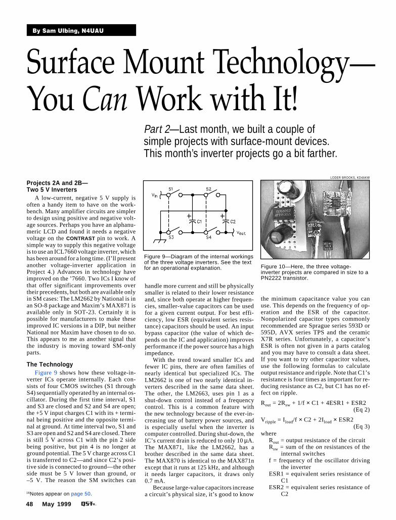
The TechnologyFigure 9 shows how these voltage-in-
verter ICs operate internally. Each con-sists of four CMOS switches (S1 throughS4) sequentially operated by an internal os-cillator. During the first time interval, S1and S3 are closed and S2 and S4 are open;the +5 V input charges C1 with its + termi-nal being positive and the opposite termi-nal at ground. At time interval two, S1 andS3 are open and S2 and S4 are closed. Thereis still 5 V across C1 with the pin 2 sidebeing positive, but pin 4 is no longer atground potential. The 5 V charge across C1is transferred to C2—and since C2’s posi-tive side is connected to ground—the otherside must be 5 V lower than ground, or–5 V. The reason the SM switches can
By Sam Ulbing, N4UAU
Surface Mount Technology—You Can Work with It!
16Notes appear on page 50.
Part 2—Last month, we built a couple ofsimple projects with surface-mount devices.This month’s inverter projects go a bit farther.
Figure 9—Diagram of the internal workingsof the three voltage inverters. See the textfor an operational explanation. Figure 10—Here, the three voltage-
inverter projects are compared in size to aPN2222 transistor.
LODER BROOKS, KD4AKW
handle more current and still be physicallysmaller is related to their lower resistanceand, since both operate at higher frequen-cies, smaller-value capacitors can be usedfor a given current output. For best effi-ciency, low ESR (equivalent series resis-tance) capacitors should be used. An inputbypass capacitor (the value of which de-pends on the IC and application) improvesperformance if the power source has a highimpedance.
With the trend toward smaller ICs andfewer IC pins, there are often families ofnearly identical but specialized ICs. TheLM2662 is one of two nearly identical in-verters described in the same data sheet.The other, the LM2663, uses pin 1 as ashut-down control instead of a frequencycontrol. This is a common feature withthe new technology because of the ever-in-creasing use of battery power sources, andis especially useful when the inverter iscomputer controlled. During shut-down, theIC’s current drain is reduced to only 10 µA.The MAX871, like the LM2662, has abrother described in the same data sheet.The MAX870 is identical to the MAX871nexcept that it runs at 125 kHz, and althoughit needs larger capacitors, it draws only0.7 mA.
Because large-value capacitors increasea circuit’s physical size, it’s good to know
the minimum capacitance value you canuse. This depends on the frequency of op-eration and the ESR of the capacitor.Nonpolarized capacitor types commonlyrecommended are Sprague series 593D or595D, AVX series TPS and the ceramicX7R series. Unfortunately, a capacitor’sESR is often not given in a parts catalogand you may have to consult a data sheet.If you want to try other capacitor values,use the following formulas to calculateoutput resistance and ripple. Note that C1’sresistance is four times as important for re-ducing resistance as C2, but C1 has no ef-fect on ripple.
Rout = 2Rsw + 1/f × C1 + 4ESR1 + ESR2(Eq 2)
Vripple = Iload/f × C2 + 2Iload × ESR2(Eq 3)
whereRout = output resistance of the circuitRsw = sum of the on resistances of the
internal switchesf = frequency of the oscillator driving
the inverterESR1 = equivalent series resistance of
C1ESR2 = equivalent series resistance of
C2

May 1999 49
Vripple = peak-to-peak ripple voltage atthe output
Iload = load current delivered by theinverter
All three ICs can be used in othermodes, such as voltage doublers, con-nected in cascade to increase output volt-age, or connected in parallel to increaseoutput current. For information on circuitsto use and more information about design
Figure 11—At A, schematics ofthe LM2662 and MAX871inverter circuits. Nonpolarizedceramic capacitors are used inthe MAX 871 circuit. See Table 1for suggested capacitancevalues. The etchless homemadeboard layouts (B) show wherethe copper foil is scored toproduce component-mountingislands and how the componentsare mounted on opposite sidesof each board. Wire jumpersmade of #26 enameled wire(labeled A, B, C and D)interconnect islands of the topfoil to those on the bottom.
consi-derations, refer to the device datasheets.
The SOT-23 is a popular IC size and itis important to develop the skills to workwith it if you want to make full use ofthe new technology. When you build theMAX871 project, set it aside because youmay find it useful in Project 4.
Table 1 summarizes some features ofthe ICs mentioned, and Figure 10 shows
you what the three completed circuitslook like. You can see that the LM2662circuit is somewhat smaller than the ’7660,yet it provides 10 times the current output!The MAX871 circuit is extremely smalland outperforms the ICL7660.
Figures 11A and 11B show the schemat-ics and board layouts, respectively. Thecircuits are simple, each requiring but twocapacitors and one IC.17
50 May 1999
Building the LM2662 CircuitTo save space, I put the IC on one side
of a double-sided board, mounting the ca-pacitors on the opposite side. Interconnec-tions between the two board sides are madeby short pieces of #26 enameled wire. Thewires (labeled A, B, C, D in Figure 11B)bend around the edge of the board. If youhave built Project 1, you will have no prob-lem with this one. Be careful to observecapacitor polarity. Even though theLM2662 is smaller than the ICL7660, itoffers more features. Pin 1 (which is notused in the ICL7660) controls the LM2662’sinternal oscillator. The inverter runs at20 kHz when this pin is left unconnected,and at 150 kHz when connected to VCC. Ifyou want the circuit to operate at 150 kHz,add a jumper between pins 1 and 8 of the IC.This allows you to use smaller capacitors,but at the price of a higher supply current.
Building the MAX871 CircuitThe first time you see this project,
you may think “It’s too small to build byhand!” But I’ve built four different circuitsthis size and made a PC board for eachone—so can you! Because the SOT-23package is smaller than the SO-8, I used a0.005-inch wheel to make the island-sepa-rating cuts on my PC board. Although theIC’s pins are small and closely spaced, theSOT-23-5 board requires only two criticalcuts: those between pins 1 and 2 and be-tween pins 2 and 3. The spacing betweenpins 4 and 5 is as large as that of an SO-8package. Mounting C2 beneath the boardmakes component layout much easier.
SOT-23 packaged devices are too smallfor manufacturers to imprint the part num-ber on them—MAX890EUK just will notfit! Instead of MAX890EUK, Maxim usesthe marking ABZO. If you get two SOTsmixed up, you will have to consult the datasheets to determine which is which.
Next MonthIn Part 3, we’ll look at a low-voltage
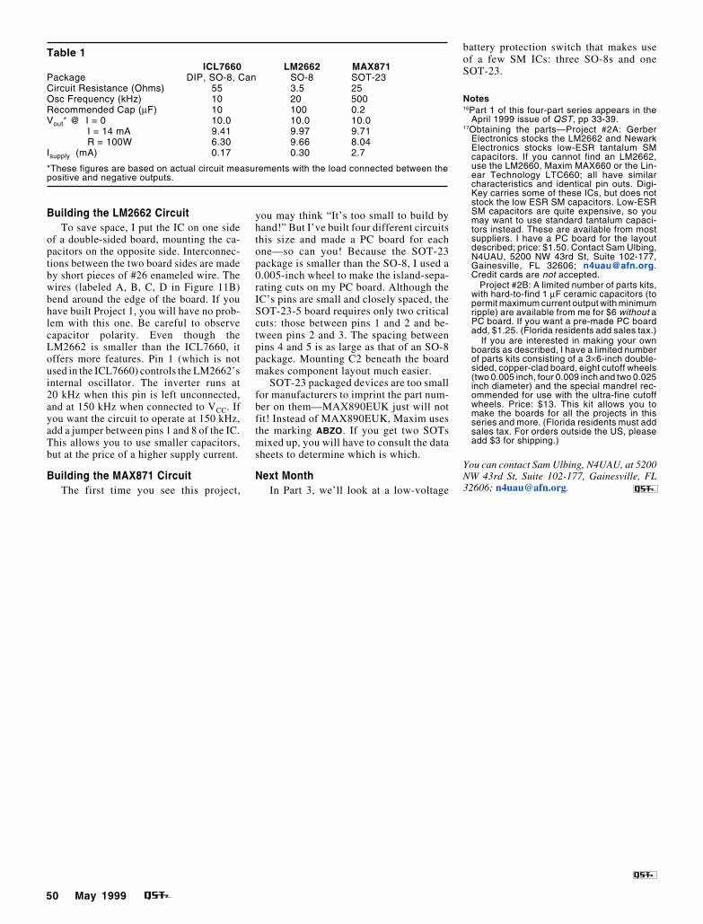
Table 1ICL7660 LM2662 MAX871
Package DIP, SO-8, Can SO-8 SOT-23Circuit Resistance (Ohms) 55 3.5 25Osc Frequency (kHz) 10 20 500Recommended Cap (µF) 10 100 0.2Vout* @ I = 0 10.0 10.0 10.0 I = 14 mA 9.41 9.97 9.71 R = 100W 6.30 9.66 8.04Isupply (mA) 0.17 0.30 2.7
*These figures are based on actual circuit measurements with the load connected between thepositive and negative outputs.
battery protection switch that makes useof a few SM ICs: three SO-8s and oneSOT-23.
Notes16Part 1 of this four-part series appears in the
April 1999 issue of QST, pp 33-39.17Obtaining the parts—Project #2A: Gerber
Electronics stocks the LM2662 and NewarkElectronics stocks low-ESR tantalum SMcapacitors. If you cannot find an LM2662,use the LM2660, Maxim MAX660 or the Lin-ear Technology LTC660; all have similarcharacteristics and identical pin outs. Digi-Key carries some of these ICs, but does notstock the low ESR SM capacitors. Low-ESRSM capacitors are quite expensive, so youmay want to use standard tantalum capaci-tors instead. These are available from mostsuppliers. I have a PC board for the layoutdescribed; price: $1.50. Contact Sam Ulbing,N4UAU, 5200 NW 43rd St, Suite 102-177,Gainesville, FL 32606; [email protected] cards are not accepted.
Project #2B: A limited number of parts kits,with hard-to-find 1 µF ceramic capacitors (topermit maximum current output with minimumripple) are available from me for $6 without aPC board. If you want a pre-made PC boardadd, $1.25. (Florida residents add sales tax.)
If you are interested in making your ownboards as described, I have a limited numberof parts kits consisting of a 3×6-inch double-sided, copper-clad board, eight cutoff wheels(two 0.005 inch, four 0.009 inch and two 0.025inch diameter) and the special mandrel rec-ommended for use with the ultra-fine cutoffwheels. Price: $13. This kit allows you tomake the boards for all the projects in thisseries and more. (Florida residents must addsales tax. For orders outside the US, pleaseadd $3 for shipping.)
You can contact Sam Ulbing, N4UAU, at 5200NW 43rd St, Suite 102-177, Gainesville, FL32606; [email protected].
34 June 1999
W
By Sam Ulbing, N4UAU
Surface Mount Technology—You Can Work with It!Part 3—This more-complex SM project employs a total of four ICs and sevenother parts on a PC board three-quarters of an inch square! Despite its smallsize, it can control current levels of up to 10 A—without using mechanical relays!
18Notes appear on page 36.
hen Hurricane Georges camethrough in 1998, my friend,Dave, N0LSK, had left his boatat a marina in the Keys. Al-
though he had the boat tied up well, he for-got that his refrigerator shifts to batterypower if the ac-line power is lost. When hereturned to the boat after the storm, his boatwas okay, but its battery was dead. Withthe switch about to be described, Davewouldn’t have lost his expensive battery.
Project 3—A Low-VoltageBattery-Protection Switch
This switch, based on a MAX835 (avail-able only in an SOT-23 case), is a latchingvoltage monitor—ideal for controlling aswitch. A recent QST project used aMAX8211 (a DIP IC) in an undervoltagecircuit,18,19 but because it doesn’t latch, thatchip wouldn’t work well for controlling aswitch. Here’s why: Every time the voltagedropped low enough to trip the monitor, itwould disconnect the load, and the voltagewould rise and turn the monitor back on.Such cycling could injure the equipment.
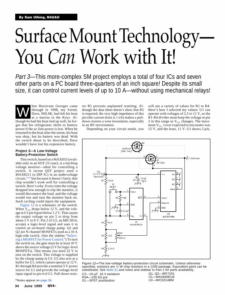
Figure 12 is a schematic of the switch.When VCC drops below 12 V, and the volt-age at U1 pin 4 goes below 1.2 V. That causesthe output voltage on pin 5 to drop fromabout 5 V to 0 V. Pin 2 of U2, an MIC5014,accepts a logic-level signal and uses it tocontrol an on-board charge pump. Q1 andQ2 are N-channel MOSFETs used as a 10 Ahigh-side switch. (See the sidebar “Select-ing a MOSFET for Power Control.”) To turnthe switch on, the gate must be at least 10 Vabove the source voltage (5 V for logic-levelMOSFETs). That means you need 22 V toturn on the switch. This voltage is suppliedby the charge pump in U2. U2 also acts as abuffer for U1, which cannot operate at 12 V.R1 through R4 provide a nominal 5 V powersource for U1 and provide the voltage-levelinput signal to pin 4 of U1. Pull-down resis-C2—10 µF, 16 V tantalum
R3A—100 kΩ potS1—SPST pushbutton
Figure 12—The low-voltage battery-protection circuit schematic. Unless otherwisespecified, resistors are 1/8 W chip resistors in a 1206 package. Equivalent parts can besubstituted. See Note 21 and notes and sidebar in Part 1 for parts availability.
Q1, Q2—IRF7201U1—MAX835EUKU2—MIC5014BM
tor R5 prevents unplanned resetting. Al-though the data sheet doesn’t show that R5is required, the very high impedance of thispin (the current drain is 1 nA) makes a pull-down resistor a wise investment, especiallyin an RF environment.
Depending on your circuit needs, you
will use a variety of values for R1 to R4.Here’s how I selected my values: U1 canoperate with voltages of 2.5 to 11 V, so theR1-R4 divider must keep the voltage at pin3 in this range as VCC changes. The maxi-mum VCC I ever expected to encounter was15 V, and the least, 11 V. U1 draws 2 µA,
June 1999 35
so to keep a stiff supply, I wanted the cur-rent through the voltage divider to be atleast 200 µA. This calls for a total resis-tance of not more than 50 kΩ. As currentdrain is not important, I decided to use atotal resistance of about 20 kΩ. Using anExcel spreadsheet, I calculated the valuesshown. The voltage on pin 3 is 5.3 V forVCC of 15 V, and 3.8 V for VCC of 11 V. Iused four fixed-value resistors and a SMpotentiometer (R3B) in parallel with R3 toallow better control when setting the triplevel at 12.0 V. You can run U1 at a lowervoltage, but keep in mind that U2 needs atleast 2 V to trigger it.
This basic circuit can be optimized forother uses. To handle more current, you needonly replace the MOSFET with a more-ro-bust one. I use an IRFZ46 and a heat sinkwith my ICOM IC-735. If you want to con-trol a low-voltage NiCd-powered circuit, youcould use U1 alone, connecting it directly toa logic level low-side N-channel MOSFET.In that case, increase the resistances of R1 toR4 for minimum current drain.
The TechnologyThere is a lot of new technology in this
simple circuit. The entire project—includ-ing the 10 A MOSFET switch—is on a PC
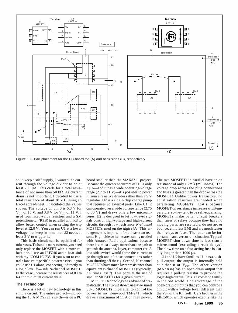
Figure 13—Part placement for the PC-board top (A) and back sides (B), respectively.
board smaller than the MAX8211 project.Because the quiescent current of U1 is only2 µA—and it has a wide operating-voltagerange (2.7 to 11 V)—it’s possible to powerit from a resistive divider rather than a 5 Vregulator. U2 is a single-chip charge pumpthat requires no external parts. Like U1, itcan operate over a wide voltage range (2.75to 30 V) and draws only a few microam-peres. U2 is designed to let low-level sig-nals control high-voltage and high-currentcircuits through low resistance N-channelMOSFETs used on the high side. This ar-rangement is important for at least two rea-sons: High-side switches are usually neededwith Amateur Radio applications becausethere is almost always more than one path toground: the antenna, keyer, computer etc. Alow-side switch would force the current togo through one of those connections ratherthan shutting off the rig. Second, N-channelMOSFETs have much lower resistance thanequivalent P-channel MOSFETs (typically,2.5 times less20). This permits the use ofsmaller MOSFETs for a given current.
MOSFET technology has advanced dra-matically. The circuit shown uses two smallSO-8 MOSFETs in parallel to control thepower to my Kenwood TM-241, whichdraws a maximum of 11 A on high power.
The two MOSFETs in parallel have an onresistance of only 15 mΩ (milliohms). Thevoltage drop across the plug connectionsand fuses is greater than the drop across theMOSFET! Unlike power transistors, noequalization resistors are needed whenparalleling MOSFETs. That’s becauseMOSFET on resistance increases with tem-perature, so they tend to be self-equalizing.MOSFETs make better circuit breakersthan fuses or relays because they have nomoving parts, are resettable, do not arc orbounce, emit less EMI and are much fasterthan relays or fuses. The latter can be im-portant in an overcurrent situation. TypicalMOSFET shut-down time is less than amicrosecond (excluding circuit delays).The blow time on a fast-acting fuse is usu-ally longer than 1000 µs.
U1 and U2 have families. U1 has a push-pull output; the output is internally heldat either 0 or VCC. The other version(MAX834) has an open-drain output thatrequires a pull-up resistor to provide thelogic-high output. This is a common familyin the SM world. One advantage of theopen-drain output is that you can control acircuit with a voltage level different thanthe VCC of the IC itself. U2’s brother is theMIC5015, which operates exactly like the
36 June 1999
’5014, but 0 V at the input turns it on, anda high level turns it off.
Making the PC BoardFigures 13A and B show the part place-
ment for the top and back sides of the PCboard for this project.21 Before I made theall-SM version (shown in Figure 14B), Ibuilt a quick-and-dirty prototype using twoPC boards. Except for the ICs, I used allstandard-size leaded parts (one side of oneof these boards is shown in Figure 14A), sothe only critical cutting area was aroundthe IC; all the rest was old-fashioned padconstruction such as used in Project 0A. Ifyou want to use an SM-only IC but don’tneed small size, this is an easy way to do it.You can also add solid wires as leads fromthe board and plug the entire circuit into aprotoboard to use the subcircuit in a largerthrough-hole circuit. If you realize that SMprojects needn’t require only SM devices,experimentation becomes easier.
Once more, four jumpers (A, B, C andD) make connections between the top andbottom sides of the board where necessary.Because the board has parts on both sides,soldering is a little trickier than dealingwith a board with parts mounted only onone side. Once you solder parts to one sideof the board and turn the board over to sol-der the backside parts, it won’t lie flat.Here’s where a small vise can help by hold-ing the board steady. I place parts on themore-congested side first. It isn’t difficultto use the two SO-8 chips because they areso large; soldering SOT-23 packages wouldbe more of a challenge.
Tune In AgainBefore we wrap up this series next
month, we’ll look at a project with a largenumber of small parts mounted on bothsides of the board. This project is one youcan use as an appeasement gift to your
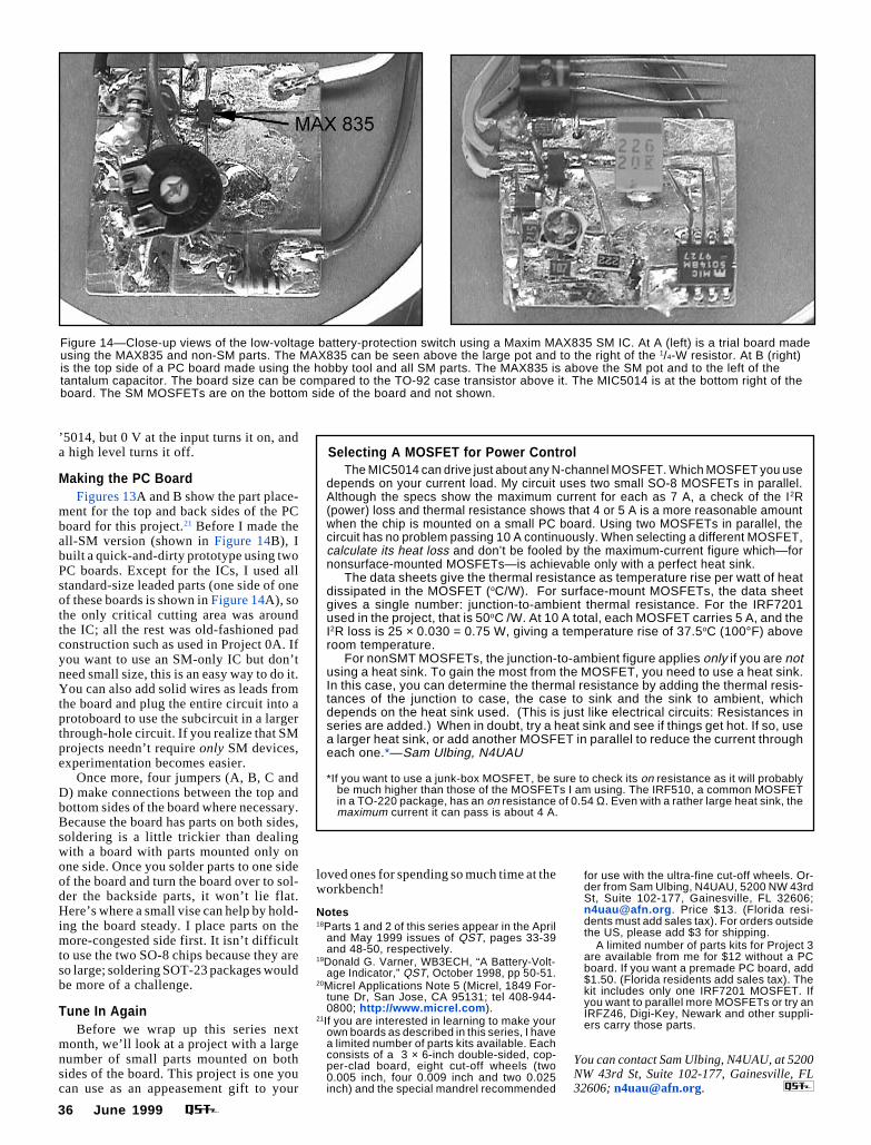
Figure 14—Close-up views of the low-voltage battery-protection switch using a Maxim MAX835 SM IC. At A (left) is a trial board madeusing the MAX835 and non-SM parts. The MAX835 can be seen above the large pot and to the right of the 1/4-W resistor. At B (right)is the top side of a PC board made using the hobby tool and all SM parts. The MAX835 is above the SM pot and to the left of thetantalum capacitor. The board size can be compared to the TO-92 case transistor above it. The MIC5014 is at the bottom right of theboard. The SM MOSFETs are on the bottom side of the board and not shown.
Selecting A MOSFET for Power ControlThe MIC5014 can drive just about any N-channel MOSFET. Which MOSFET you use
depends on your current load. My circuit uses two small SO-8 MOSFETs in parallel.Although the specs show the maximum current for each as 7 A, a check of the I2R(power) loss and thermal resistance shows that 4 or 5 A is a more reasonable amountwhen the chip is mounted on a small PC board. Using two MOSFETs in parallel, thecircuit has no problem passing 10 A continuously. When selecting a different MOSFET,calculate its heat loss and don’t be fooled by the maximum-current figure which—fornonsurface-mounted MOSFETs—is achievable only with a perfect heat sink.
The data sheets give the thermal resistance as temperature rise per watt of heatdissipated in the MOSFET (oC/W). For surface-mount MOSFETs, the data sheetgives a single number: junction-to-ambient thermal resistance. For the IRF7201used in the project, that is 50oC /W. At 10 A total, each MOSFET carries 5 A, and theI2R loss is 25 × 0.030 = 0.75 W, giving a temperature rise of 37.5oC (100°F) aboveroom temperature.
For nonSMT MOSFETs, the junction-to-ambient figure applies only if you are notusing a heat sink. To gain the most from the MOSFET, you need to use a heat sink.In this case, you can determine the thermal resistance by adding the thermal resis-tances of the junction to case, the case to sink and the sink to ambient, whichdepends on the heat sink used. (This is just like electrical circuits: Resistances inseries are added.) When in doubt, try a heat sink and see if things get hot. If so, usea larger heat sink, or add another MOSFET in parallel to reduce the current througheach one.*—Sam Ulbing, N4UAU
*If you want to use a junk-box MOSFET, be sure to check its on resistance as it will probablybe much higher than those of the MOSFETs I am using. The IRF510, a common MOSFETin a TO-220 package, has an on resistance of 0.54 Ω. Even with a rather large heat sink, themaximum current it can pass is about 4 A.
loved ones for spending so much time at theworkbench!
Notes18Parts 1 and 2 of this series appear in the April
and May 1999 issues of QST, pages 33-39and 48-50, respectively.
19Donald G. Varner, WB3ECH, “A Battery-Volt-age Indicator,” QST, October 1998, pp 50-51.
20Micrel Applications Note 5 (Micrel, 1849 For-tune Dr, San Jose, CA 95131; tel 408-944-0800; http://www.micrel.com ).
21If you are interested in learning to make yourown boards as described in this series, I havea limited number of parts kits available. Eachconsists of a 3 × 6-inch double-sided, cop-per-clad board, eight cut-off wheels (two0.005 inch, four 0.009 inch and two 0.025inch) and the special mandrel recommended
for use with the ultra-fine cut-off wheels. Or-der from Sam Ulbing, N4UAU, 5200 NW 43rdSt, Suite 102-177, Gainesville, FL 32606;[email protected] . Price $13. (Florida resi-dents must add sales tax). For orders outsidethe US, please add $3 for shipping.
A limited number of parts kits for Project 3are available from me for $12 without a PCboard. If you want a premade PC board, add$1.50. (Florida residents add sales tax). Thekit includes only one IRF7201 MOSFET. Ifyou want to parallel more MOSFETs or try anIRFZ46, Digi-Key, Newark and other suppli-ers carry those parts.
You can contact Sam Ulbing, N4UAU, at 5200NW 43rd St, Suite 102-177, Gainesville, FL32606; [email protected].
38 July 1999
T
By Sam Ulbing, N4UAU
22Notes appear on page 41.
Surface Mount Technology—You Can Work with It!
he first three parts of this arti-cle22 have described rather easy-to-build projects. This one is abit more complex. If you like to
experiment, you have the opportunity totailor this project to your specific needs andoptimize its operation. Build it for a lovedone and impress them with your skills! Ifyou spend as much time working on elec-tronic projects as I do, that loved one mightappreciate a little project like this made justfor them!
Project 4—The Hourglass 10-MinuteTimer
This month’s project is a modernized
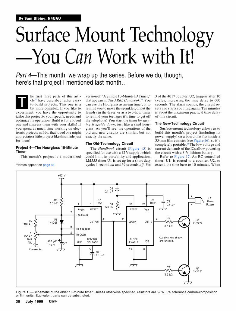
Figure 15—Schematic of the older 10-minute timer. Unless otherwise specified, resistors are 1/4 W, 5% tolerance carbon-compositionor film units. Equivalent parts can be substituted.
Part 4—This month, we wrap up the series. Before we do, though,here’s that project I mentioned last month…
version of “A Simple 10-Minute ID Timer,”that appears in The ARRL Handbook.23 Youcan use the Hourglass as an egg timer, or toremind you to move the sprinkler, or put thelaundry in the dryer, or as a two-hour timerto remind your teenager it’s time to get offthe telephone! You start the timer by turn-ing it upside down, just like a sand hour-glass! As you’ll see, the operations of theold and new circuits are similar, but notexactly the same.
The Old-Technology CircuitThe Handbook circuit (Figure 15) is
specified for use with a 12 V supply, whichcould limit its portability and application.LM555 timer U1 is set up for a short dutycycle: 1 second on and 59 seconds off. Pin
3 of the 4017 counter, U2, triggers after 10cycles, increasing the time delay to 600seconds. The alarm sounds, the circuit re-sets and starts counting again. Ten minutesis about the maximum practical time delayof this circuit.
The New-Technology CircuitSurface-mount technology allows us to
build this month’s project (including itspower supply) on a board that fits inside a35-mm film canister (see Figure 16), so it’scompletely portable.24 The low voltage andcurrent demands of the ICs allow poweringthe circuit with a 3-V lithium battery.
Refer to Figure 17. An RC controlledtimer, U1, is routed to a counter, U2, toextend the time base to 10 minutes. When
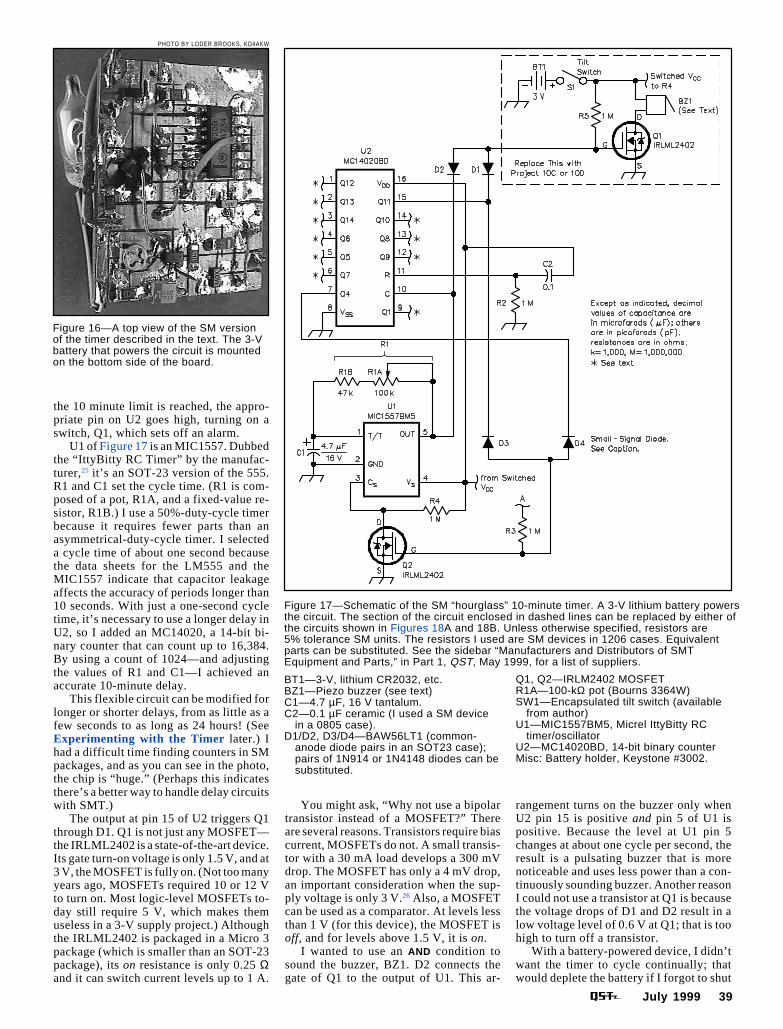
July 1999 39
the 10 minute limit is reached, the appro-priate pin on U2 goes high, turning on aswitch, Q1, which sets off an alarm.
U1 of Figure 17 is an MIC1557. Dubbedthe “IttyBitty RC Timer” by the manufac-turer,25 it’s an SOT-23 version of the 555.R1 and C1 set the cycle time. (R1 is com-posed of a pot, R1A, and a fixed-value re-sistor, R1B.) I use a 50%-duty-cycle timerbecause it requires fewer parts than anasymmetrical-duty-cycle timer. I selecteda cycle time of about one second becausethe data sheets for the LM555 and theMIC1557 indicate that capacitor leakageaffects the accuracy of periods longer than10 seconds. With just a one-second cycletime, it’s necessary to use a longer delay inU2, so I added an MC14020, a 14-bit bi-nary counter that can count up to 16,384.By using a count of 1024—and adjustingthe values of R1 and C1—I achieved anaccurate 10-minute delay.
This flexible circuit can be modified forlonger or shorter delays, from as little as afew seconds to as long as 24 hours! (SeeExperimenting with the Timer later.) Ihad a difficult time finding counters in SMpackages, and as you can see in the photo,the chip is “huge.” (Perhaps this indicatesthere’s a better way to handle delay circuitswith SMT.)
The output at pin 15 of U2 triggers Q1through D1. Q1 is not just any MOSFET—the IRLML2402 is a state-of-the-art device.Its gate turn-on voltage is only 1.5 V, and at3 V, the MOSFET is fully on. (Not too manyyears ago, MOSFETs required 10 or 12 Vto turn on. Most logic-level MOSFETs to-day still require 5 V, which makes themuseless in a 3-V supply project.) Althoughthe IRLML2402 is packaged in a Micro 3package (which is smaller than an SOT-23package), its on resistance is only 0.25 Ωand it can switch current levels up to 1 A.
Figure 16—A top view of the SM versionof the timer described in the text. The 3-Vbattery that powers the circuit is mountedon the bottom side of the board.
Figure 17—Schematic of the SM “hourglass” 10-minute timer. A 3-V lithium battery powersthe circuit. The section of the circuit enclosed in dashed lines can be replaced by either ofthe circuits shown in Figures 18A and 18B. Unless otherwise specified, resistors are5% tolerance SM units. The resistors I used are SM devices in 1206 cases. Equivalentparts can be substituted. See the sidebar “Manufacturers and Distributors of SMTEquipment and Parts,” in Part 1, QST, May 1999, for a list of suppliers.
You might ask, “Why not use a bipolartransistor instead of a MOSFET?” Thereare several reasons. Transistors require biascurrent, MOSFETs do not. A small transis-tor with a 30 mA load develops a 300 mVdrop. The MOSFET has only a 4 mV drop,an important consideration when the sup-ply voltage is only 3 V.26 Also, a MOSFETcan be used as a comparator. At levels lessthan 1 V (for this device), the MOSFET isoff, and for levels above 1.5 V, it is on.
I wanted to use an AND condition tosound the buzzer, BZ1. D2 connects thegate of Q1 to the output of U1. This ar-
rangement turns on the buzzer only whenU2 pin 15 is positive and pin 5 of U1 ispositive. Because the level at U1 pin 5changes at about one cycle per second, theresult is a pulsating buzzer that is morenoticeable and uses less power than a con-tinuously sounding buzzer. Another reasonI could not use a transistor at Q1 is becausethe voltage drops of D1 and D2 result in alow voltage level of 0.6 V at Q1; that is toohigh to turn off a transistor.
With a battery-powered device, I didn’twant the timer to cycle continually; thatwould deplete the battery if I forgot to shut
BT1—3-V, lithium CR2032, etc.BZ1—Piezo buzzer (see text)C1—4.7 µF, 16 V tantalum.C2—0.1 µF ceramic (I used a SM device
in a 0805 case).D1/D2, D3/D4—BAW56LT1 (common-
anode diode pairs in an SOT23 case);pairs of 1N914 or 1N4148 diodes can besubstituted.
Q1, Q2—IRLM2402 MOSFETR1A—100-kΩ pot (Bourns 3364W)SW1—Encapsulated tilt switch (available
from author)U1—MIC1557BM5, Micrel IttyBitty RC
timer/oscillatorU2—MC14020BD, 14-bit binary counterMisc: Battery holder, Keystone #3002.
PHOTO BY LODER BROOKS, KD4AKW
40 July 1999
off the timer. This circuit shuts itself off.The buzzer sounds for about three seconds,and if it is not restarted, the circuit goes tosleep. It works like this: D3 and D4 form anAND gate controlling Q2. After pin 15 ofU1 goes high and the buzzer sounds, thetimer continues to count until U2 pin 7 alsogoes high. Then, Q2 turns on and pin 3 ofU1 goes low. Pin 3 is U1’s CHIP SELECTpin; when it goes low, U1 stops runningand its current drain is reduced to 1 µA.With U1 sleeping, its output goes low. Thatshuts off the buzzer via D2. Total currentdrain while sleeping is about 5 µA. Underthese conditions, a lithium 2032 batteryshould last several years.
To restart the timer (from sleep mode orwhen it is buzzing), just turn it upside downand then right side up. The tilt switch turnsthe power off, then on. C2 and R2 form apower-up reset that restarts U2 at 0 with apositive pulse to pin 11 through C2.
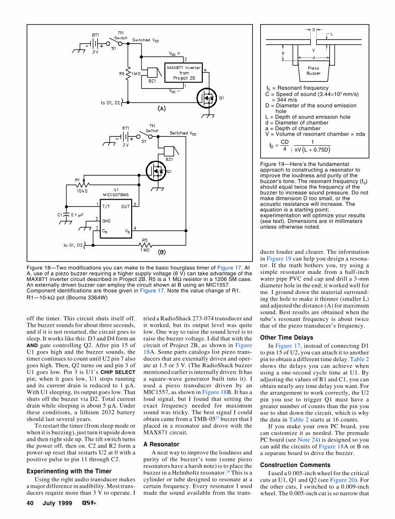
Experimenting with the TimerUsing the right audio transducer makes
a major difference in audibility. Most trans-ducers require more than 3 V to operate. I
Figure 18—Two modifications you can make to the basic hourglass timer of Figure 17. AtA, use of a piezo buzzer requiring a higher supply voltage (6 V) can take advantage of theMAX871 inverter circuit described in Project 2B. R5 is a 1 MΩ resistor in a 1206 SM case.An externally driven buzzer can employ the circuit shown at B using an MIC1557.Component identifications are those given in Figure 17. Note the value change of R1.R1—10-kΩ pot (Bourns 3364W)
Figure 19—Here’s the fundamentalapproach to constructing a resonator toimprove the loudness and purity of thebuzzer’s tone. The resonant frequency (f0)should equal twice the frequency of thebuzzer to increase sound pressure. Do notmake dimension D too small, or theacoustic resistance will increase. Theequation is a starting point;experimentation will optimize your results(see text). Dimensions are in millimetersunless otherwise noted.
tried a RadioShack 273-074 transducer andit worked, but its output level was quitelow. One way to raise the sound level is toraise the buzzer voltage. I did that with thecircuit of Project 2B, as shown in Figure18A. Some parts catalogs list piezo trans-ducers that are externally driven and oper-ate at 1.5 or 3 V. (The RadioShack buzzermentioned earlier is internally driven: It hasa square-wave generator built into it). Iused a piezo transducer driven by anMIC1557, as shown in Figure 18B. It has aloud signal, but I found that setting theexact frequency needed for maximumsound was tricky. The best signal I couldobtain came from a TMB-0527 buzzer that Iplaced in a resonator and drove with theMAX871 circuit.
A ResonatorA neat way to improve the loudness and
purity of the buzzer’s tone (some piezoresonators have a harsh note) is to place thebuzzer in a Helmholtz resonator.28 This is acylinder or tube designed to resonate at acertain frequency. Every resonator I usedmade the sound available from the trans-
ducer louder and clearer. The informationin Figure 19 can help you design a resona-tor. If the math bothers you, try using asimple resonator made from a half-inchwater pipe PVC end cap and drill a 3-mmdiameter hole in the end; it worked well forme. I ground down the material surround-ing the hole to make it thinner (smaller L)and adjusted the distance (A) for maximumsound. Best results are obtained when thetube’s resonant frequency is about twicethat of the piezo transducer’s frequency.
Other Time DelaysIn Figure 17, instead of connecting D1
to pin 15 of U2, you can attach it to anotherpin to obtain a different time delay. Table 2shows the delays you can achieve whenusing a one-second cycle time at U1. Byadjusting the values of R1 and C1, you canobtain nearly any time delay you want. Forthe arrangement to work correctly, the U2pin you use to trigger Q1 must have agreater number of counts than the pin youuse to shut down the circuit, which is whythe data in Table 2 starts at 16 counts.
If you make your own PC board, youcan customize it as needed. The premadePC board (see Note 24) is designed so youcan add the circuits of Figure 18A or B ona separate board to drive the buzzer.
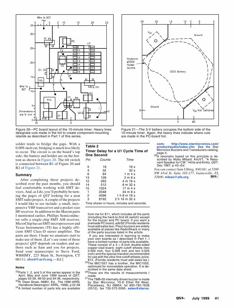
Construction CommentsI used a 0.005-inch wheel for the critical
cuts at U1, Q1 and Q2 (see Figure 20). Forthe other cuts, I switched to a 0.009-inchwheel. The 0.005-inch cut is so narrow that
f0 = Resonant frequencyC = Speed of sound (3.44×105 mm/s) = 344 m/sD = Diameter of the sound emission
holeL = Depth of sound emission holed = Diameter of chambera = Depth of chamberV = Volume of resonant chamber = πda
fCD4
1V L 0.75D
0 =+( )π
July 1999 41
Figure 21—The 3-V battery occupies the bottom side of the10-minute timer. Again, the heavy lines indicate where cutsare made in the PC-board foil.
Table 2Timer Delay for a U1 Cycle Time ofOne SecondPin Counts Time
5 16 16 s 4 32 32 s 6 64 1 m 4 s13 128 2 m 8 s12 265 4 m 16 s14 512 8 m 32 s15 1024 17 m 4 s 1 2048 34 m 8 s 2 4096 1 h 8 m 16 s 3 8192 2 h 16 m 32 sTime shown in hours, minutes and seconds.
Figure 20—PC board layout of the 10-minute timer. Heavy linesdesignate cuts made in the foil to create component-mountingislands as described in Part 1 of this series.
solder tends to bridge the gaps. With a0.009-inch cut, bridging is much less likelyto occur. The circuit is on the board’s topside; the battery and holder are on the bot-tom as shown in Figure 20. The tilt switchis connected between B1 of Figure 20 andB2 of Figure 21.
SummaryAfter completing these projects de-
scribed over the past months, you shouldfeel comfortable working with SMT de-vices. And, as I do, you’ll probably be turn-ing the pages of QST looking for a neatSMT radio project. A couple of the projectsI would like to see include: a small, inex-pensive VHF transceiver and a pocket-sizeHF receiver. In addition to the Maxim partsI mentioned earlier, Phillips Semiconduc-tor sells a single-chip SMT AM receiver,MicroChip has an SMT microprocessor andTexas Instruments (TI) has a highly effi-cient SMT Class-D stereo amplifier. Theparts are there. I hope we amateurs start tomake use of them. [Let’s see some of thoseprojects! QST depends on readers and au-thors such as Sam and you for projects.Send your manuscripts to Steve Ford,WB8IMY, 225 Main St, Newington, CT06111; [email protected].—Ed.]
Notes22Parts 1, 2, and 3 of this series appear in the
April, May and June 1999 issues of QST,pages 33-39, 48-50 and 34-36, respectively.
23R. Dean Straw, N6BV, Ed., The 1999 ARRLHandbook (Newington: ARRL, 1998), p 22.58
24A limited number of parts kits are available
from me for $11, which includes all the parts(including the hard-to-find tilt switch) exceptfor the buzzer and PC board. If you want apremade PC board, add $2 (Florida residentsmust add sales tax). Piezo buzzers are widelyavailable at places like RadioShack or manyof the parts sources listed in the article.
If you are interested in learning to makeyour own boards as I described in Part 1, Ihave a limited number of parts kits available.These consist of a 3 × 6-inch double-sidedcopper-clad board, eight cutoff wheels (two0.005 inch, four 0.009 inch and two 0.025inch) and the special mandrel recommendedfor use with the ultra-fine cutoff wheels; price:$13. (Florida residents must add sales tax.)
25The MIC1557 has a brother, the MIC1555,optimized for monostable operation. It is de-scribed in the same data sheet.
26These are the results of measurements Imade.
27The TMB-05 internally driven buzzer is madeby Star Micronics, 70-D Ethel Rd West,Piscataway, NJ 08854; tel 800-782-7636(X512), fax 732-572-5095; sales@starus.
com; http://www.starmicronics.com/product/audio/index.cfm. See the StarMicronics Buzzers and Transducers catalog,page 5.
28A resonator based on this principle is de-scribed by Wally Millard, K4JVT, “A Reso-nant Speaker for CW,” Hints and Kinks, QST,Dec 1987, p 43–Ed.
You can contact Sam Ulbing, N4UAU, at 5200NW 43rd St, Suite 102-177, Gainesville, FL32606; [email protected].