supplemental restraint system (srs) (if engine … - engine electrical... · supplemental restraint...
TRANSCRIPT
SJC8A000000000J0401ABAT00
SUPPLEMENTAL RESTRAINT SYSTEM (SRS) (If engine electrical maintenance is required)
The Ridgeline SRS includes a driver’s airbag in the steering wheel hub, a passenger’s airbag in the dashboard abovethe glove box, seat belt tensioners in the front seat belt retractors, side curtain airbags in the sides of the roof, and sideairbags in the front seat-backs. Information necessary to safely service the SRS is included in this Service Manual.Items marked with an asterisk ( ) on the contents page include or are located near SRS components. Servicing,disassembling, or replacing these items requires special precautions and tools, and should be done by an authorizedHonda dealer.
• To avoid rendering the SRS inoperative, which could lead to personal injury or death in the event of a severe frontalor side collision, all SRS service work should be done by an authorized Honda dealer.
• Improper service procedures, including incorrect removal and installation of the SRS, could lead to personal injurycaused by unintentional deployment of the airbags and/or side airbags.
• Do not bump or impact the SRS unit, front impact sensors, or side impact sensors when the ignition switch is ON (II),or for at least 3 minutes after the ignition switch is turned OFF; otherwise, the system may fail in a collision, or theairbags may deploy.
• SRS electrical connectors are identified by yellow color coding. Related components are located in the steeringcolumn, front console, dashboard, dashboard lower panel, in the dashboard above the glove box, in the front seats,in the roof side, and around the floor. Do not use electrical test equipment on these circuits.
07/05/09 16:32:44 61SJC020_040_0001
SJC8A000000000J0401ZCAT00
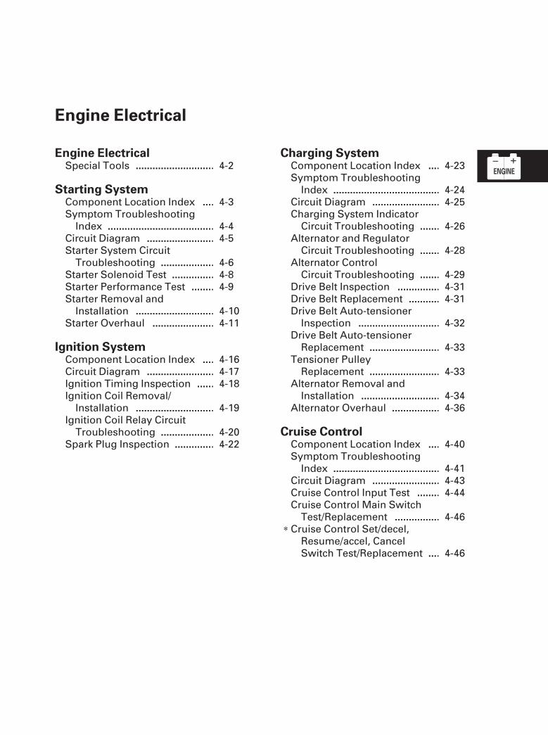
Engine Electrical
Engine Electrical
Starting System
Ignition System
Charging System
Cruise Control
......................................................Special Tools . 4-2
...
............................................................
................................
.......
................................................
...
............................................................
................................
.......
................................................
Component Location Index . 4-3Symptom Troubleshooting
Index . 4-4Circuit Diagram . 4-5Starter System Circuit
Troubleshooting . 4-6Starter Solenoid Test . 4-8Starter Performance Test . 4-9Starter Removal and
Installation . 4-10Starter Overhaul . 4-11
..........................
.....
...........................
...............................
..........................
.....
...........................
...............................
Component Location Index . 4-16Circuit Diagram . 4-17Ignition Timing Inspection . 4-18Ignition Coil Removal/
Installation . 4-19Ignition Coil Relay Circuit
Troubleshooting . 4-20Spark Plug Inspection . 4-22
...
............................................................
......
......
....................
..........
............................
........................
........................
...........................................
...
............................................................
......
......
....................
..........
............................
........................
........................
...........................................
Component Location Index . 4-23Symptom Troubleshooting
Index . 4-24Circuit Diagram . 4-25Charging System Indicator
Circuit Troubleshooting . 4-26Alternator and Regulator
Circuit Troubleshooting . 4-28Alternator Control
Circuit Troubleshooting . 4-29Drive Belt Inspection . 4-31Drive Belt Replacement . 4-31Drive Belt Auto-tensioner
Inspection . 4-32Drive Belt Auto-tensioner
Replacement . 4-33Tensioner Pulley
Replacement . 4-33Alternator Removal and
Installation . 4-34Alternator Overhaul . 4-36
...
............................................................
.......
...............
...
...
............................................................
.......
...............
...
Component Location Index . 4-40Symptom Troubleshooting
Index . 4-41Circuit Diagram . 4-43Cruise Control Input Test . 4-44Cruise Control Main Switch
Test/Replacement . 4-46Cruise Control Set/decel,
Resume/accel, CancelSwitch Test/Replacement . 4-46
07/05/09 16:32:44 61SJC020_040_0002
0101
SJC8A000000000J0401PAAT00
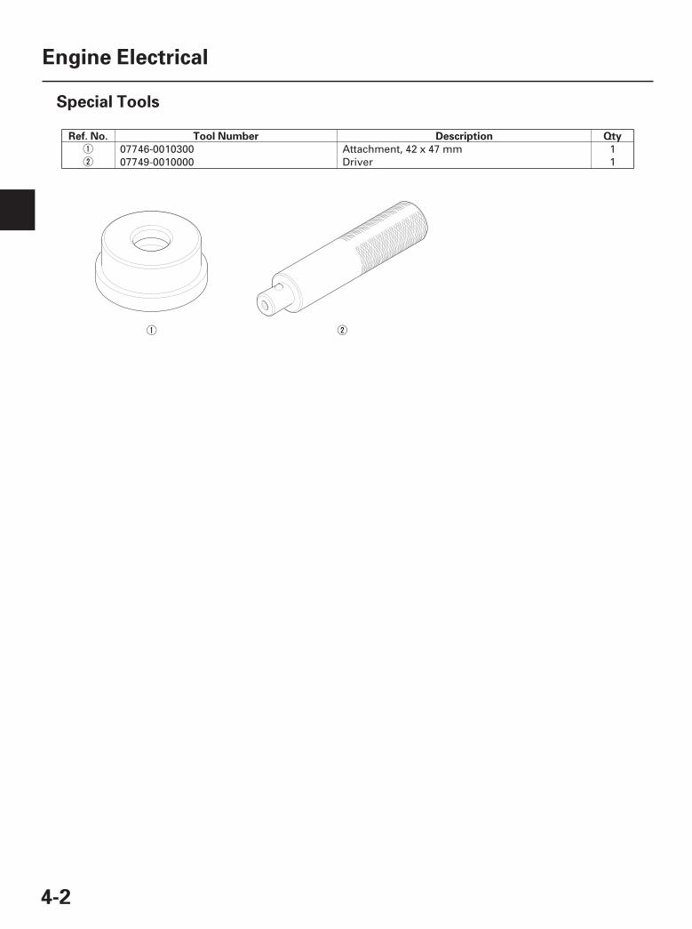
Ref. No. Tool Number Description Qty
4-2
Engine Electrical
Special Tools
07746-0010300 Attachment, 42 x 47 mm 107749-0010000 Driver 1
07/05/09 16:32:44 61SJC020_040_0003
*01
*02
SJC8A00A46500000000DAAT00
4-3
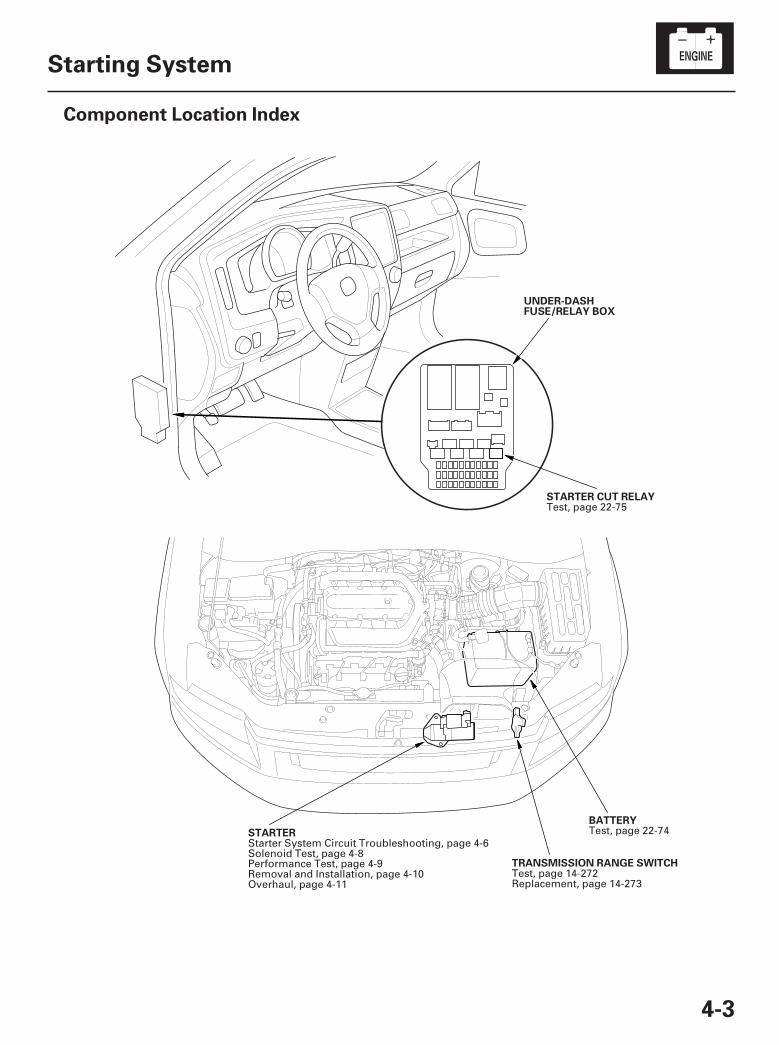
Starting System
Component Location Index
UNDER-DASHFUSE/RELAY BOX
STARTER CUT RELAY
STARTER
TRANSMISSION RANGE SWITCH
BATTERY
Test, page 22-75
Starter System Circuit Troubleshooting, page 4-6Solenoid Test, page 4-8Performance Test, page 4-9Removal and Installation, page 4-10Overhaul, page 4-11
Test, page 14-272Replacement, page 14-273
Test, page 22-74
07/05/09 16:32:47 61SJC020_040_0004
SJC8A00A46500000000HBAT01
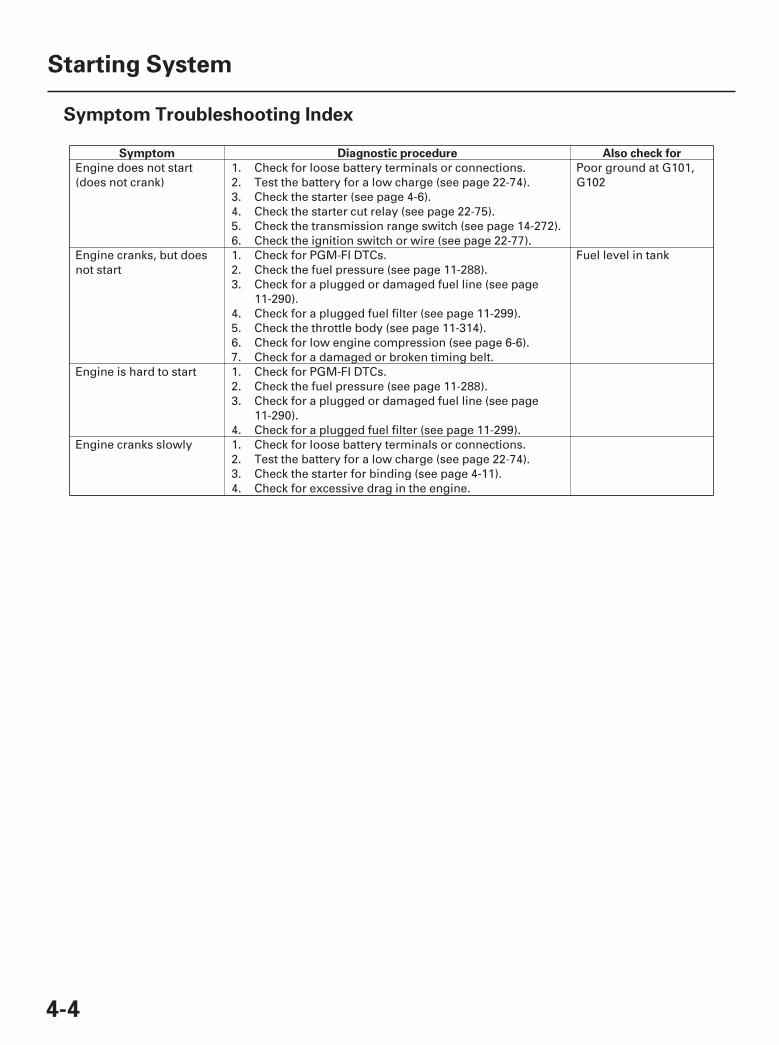
Symptom Diagnostic procedure Also check for
4-4
Starting System
Symptom Troubleshooting Index
Engine does not start(does not crank)
1.2.3.4.5.6.
Check for loose battery terminals or connections.Test the battery for a low charge (see page 22-74).Check the starter (see page 4-6).Check the starter cut relay (see page 22-75).Check the transmission range switch (see page 14-272).Check the ignition switch or wire (see page 22-77).
Poor ground at G101,G102
Engine cranks, but doesnot start
1.2.3.
4.5.6.7.
Check for PGM-FI DTCs.Check the fuel pressure (see page 11-288).Check for a plugged or damaged fuel line (see page11-290).Check for a plugged fuel filter (see page 11-299).Check the throttle body (see page 11-314).Check for low engine compression (see page 6-6).Check for a damaged or broken timing belt.
Fuel level in tank
Engine is hard to start 1.2.3.
4.
Check for PGM-FI DTCs.Check the fuel pressure (see page 11-288).Check for a plugged or damaged fuel line (see page11-290).Check for a plugged fuel filter (see page 11-299).
Engine cranks slowly 1.2.3.4.
Check for loose battery terminals or connections.Test the battery for a low charge (see page 22-74).Check the starter for binding (see page 4-11).Check for excessive drag in the engine.
07/05/09 16:32:47 61SJC020_040_0005
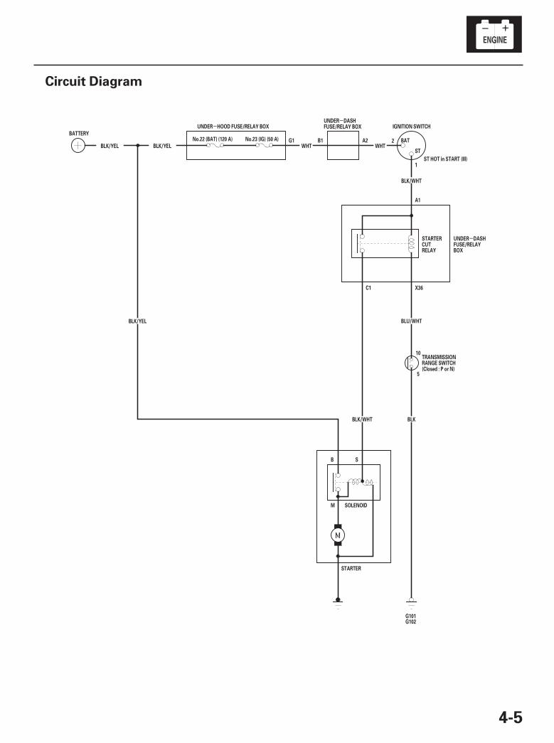
*01
SJC8A00A46500000000EAAT00
-
-
-
4-5
Circuit Diagram
B1 A2WHT
5
10
X36C1
A1
G1BLK/YEL WHTBLK/YEL
BLU/WHT
ST HOT in START (III)
G102G101
BLK/YEL
SOLENOIDM
B S
STARTER
BLK
BLK/WHT
BLK/WHT
UNDER HOOD FUSE/RELAY BOX
BATTERYNo.23 (IG) (50 A)No.22 (BAT) (120 A)
ST
BAT
IGNITION SWITCH
STARTERCUTRELAY
TRANSMISSIONRANGE SWITCH(Closed : P or N)
UNDER DASHFUSE/RELAYBOX
UNDER DASHFUSE/RELAY BOX
2
1
07/05/09 16:32:47 61SJC020_040_0006
--
01
SJC8A00A46500000000FAAT00
-
-
-
-
YES
NO
YES
NO
4-6
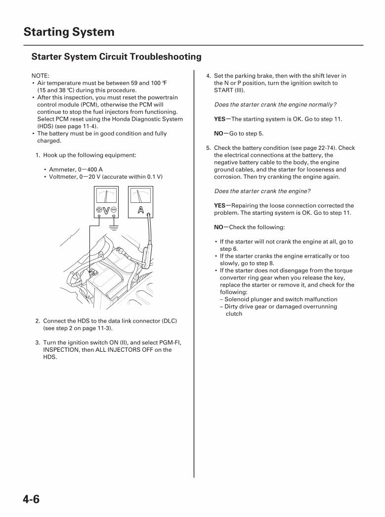
Starting System
Starter System Circuit Troubleshooting
NOTE:• Air temperature must be between 59 and 100 °F
(15 and 38 °C) during this procedure.• After this inspection, you must reset the powertrain
control module (PCM), otherwise the PCM willcontinue to stop the fuel injectors from functioning.Select PCM reset using the Honda Diagnostic System(HDS) (see page 11-4).
• The battery must be in good condition and fullycharged.
1. Hook up the following equipment:
• Ammeter, 0 400 A• Voltmeter, 0 20 V (accurate within 0.1 V)
2. Connect the HDS to the data link connector (DLC)(see step 2 on page 11-3).
3. Turn the ignition switch ON (II), and select PGM-FI,INSPECTION, then ALL INJECTORS OFF on theHDS.
4. Set the parking brake, then with the shift lever inthe N or P position, turn the ignition switch toSTART (III).
The starting system is OK. Go to step 11.
Go to step 5.
5. Check the battery condition (see page 22-74). Checkthe electrical connections at the battery, thenegative battery cable to the body, the engineground cables, and the starter for looseness andcorrosion. Then try cranking the engine again.
Repairing the loose connection corrected theproblem. The starting system is OK. Go to step 11.
Check the following:
• If the starter will not crank the engine at all, go tostep 6.
• If the starter cranks the engine erratically or tooslowly, go to step 8.
• If the starter does not disengage from the torqueconverter ring gear when you release the key,replace the starter or remove it, and check for thefollowing:– Solenoid plunger and switch malfunction– Dirty drive gear or damaged overrunning
clutch
Does the starter crank the engine normally?
Does the starter crank the engine?
07/05/09 16:32:47 61SJC020_040_0007
02
-
-
-
-
-
-
YES
NO
YES
NO
YES
NO
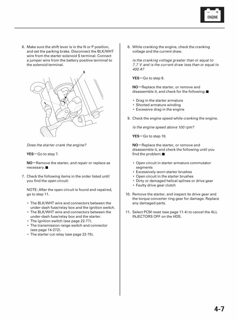
4-7
S
6. Make sure the shift lever is in the N or P position,and set the parking brake. Disconnect the BLK/WHTwire from the starter solenoid S terminal. Connecta jumper wire from the battery positive terminal tothe solenoid terminal.
Go to step 7.
Remove the starter, and repair or replace asnecessary.
7. Check the following items in the order listed untilyou find the open circuit:
NOTE: After the open circuit is found and repaired,go to step 11.
• The BLK/WHT wire and connectors between theunder-dash fuse/relay box and the ignition switch.
• The BLK/WHT wire and connectors between theunder-dash fuse/relay box and the starter.
• The ignition switch (see page 22-77).• The transmission range switch and connector
(see page 14-272).• The starter cut relay (see page 22-75).
8. While cranking the engine, check the crankingvoltage and the current draw.
Go to step 9.
Replace the starter, or remove anddisassemble it, and check for the following:
• Drag in the starter armature• Shorted armature winding• Excessive drag in the engine
9. Check the engine speed while cranking the engine.
Go to step 10.
Replace the starter, or remove anddisassemble it, and check the following until youfind the problem:
• Open circuit in starter armature commutatorsegments
• Excessively worn starter brushes• Open circuit in the starter brushes• Dirty or damaged helical splines or drive gear• Faulty drive gear clutch
10. Remove the starter, and inspect its drive gear andthe torque converter ring gear for damage. Replaceany damaged parts.
11. Select PCM reset (see page 11-4) to cancel the ALLINJECTORS OFF on the HDS.
Does the starter crank the engine?
Is the cranking voltage greater than or equal to7.7 V and is the current draw less than or equal to400 A?
Is the engine speed above 100 rpm?
07/05/09 16:32:47 61SJC020_040_0008
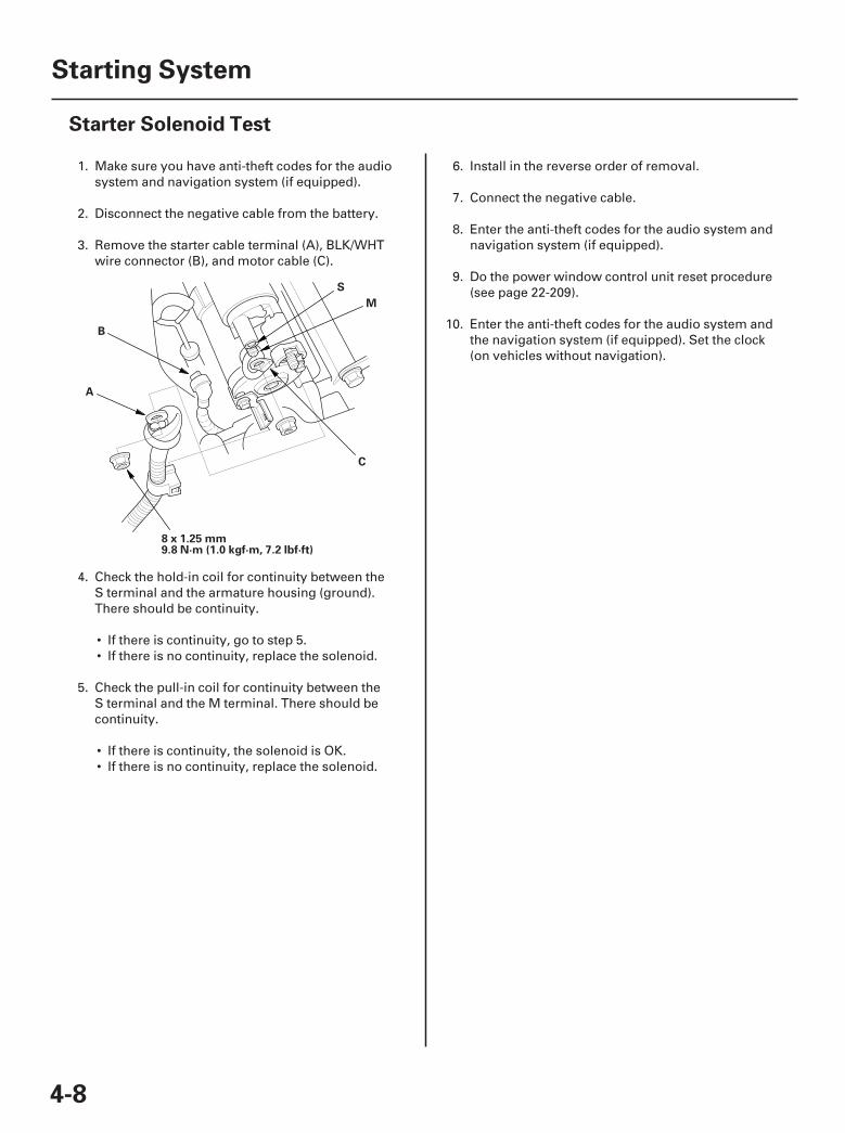
01
SJC8A00A46500056941FEAT00
4-8
Starting System
Starter Solenoid Test
8 x 1.25 mm9.8 N·m (1.0 kgf·m, 7.2 lbf·ft)
A
B
C
M
S
1. Make sure you have anti-theft codes for the audiosystem and navigation system (if equipped).
2. Disconnect the negative cable from the battery.
3. Remove the starter cable terminal (A), BLK/WHTwire connector (B), and motor cable (C).
4. Check the hold-in coil for continuity between theS terminal and the armature housing (ground).There should be continuity.
• If there is continuity, go to step 5.• If there is no continuity, replace the solenoid.
5. Check the pull-in coil for continuity between theS terminal and the M terminal. There should becontinuity.
• If there is continuity, the solenoid is OK.• If there is no continuity, replace the solenoid.
6. Install in the reverse order of removal.
7. Connect the negative cable.
8. Enter the anti-theft codes for the audio system andnavigation system (if equipped).
9. Do the power window control unit reset procedure(see page 22-209).
10. Enter the anti-theft codes for the audio system andthe navigation system (if equipped). Set the clock(on vehicles without navigation).
07/05/09 16:32:48 61SJC020_040_0009
01
02
03
04
SJC8A00A46500056901FEAT00
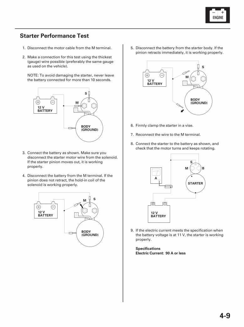
Specifications
Electric Current: 90 A or less
4-9
Starter Performance Test
12 VBATTERY
BODY(GROUND)
S
M
12 VBATTERY
BODY(GROUND)
SM
12 VBATTERY
BODY(GROUND)
S
M
A
12 VBATTERY
STARTER
B
S
M
1. Disconnect the motor cable from the M terminal.
2. Make a connection for this test using the thickest(gauge) wire possible (preferably the same gaugeas used on the vehicle).
NOTE: To avoid damaging the starter, never leavethe battery connected for more than 10 seconds.
3. Connect the battery as shown. Make sure youdisconnect the starter motor wire from the solenoid.If the starter pinion moves out, it is workingproperly.
4. Disconnect the battery from the M terminal. If thepinion does not retract, the hold-in coil of thesolenoid is working properly.
5. Disconnect the battery from the starter body. If thepinion retracts immediately, it is working properly.
6. Firmly clamp the starter in a vise.
7. Reconnect the wire to the M terminal.
8. Connect the starter to the battery as shown, andcheck that the motor turns and keeps rotating.
9. If the electric current meets the specification whenthe battery voltage is at 11 V, the starter is workingproperly.
07/05/09 16:32:48 61SJC020_040_0010
01
01
SJC8A00A46500056901KDAT00
Removal Installation
4-10
Starting System
Starter Removal and Installation
B
A
C
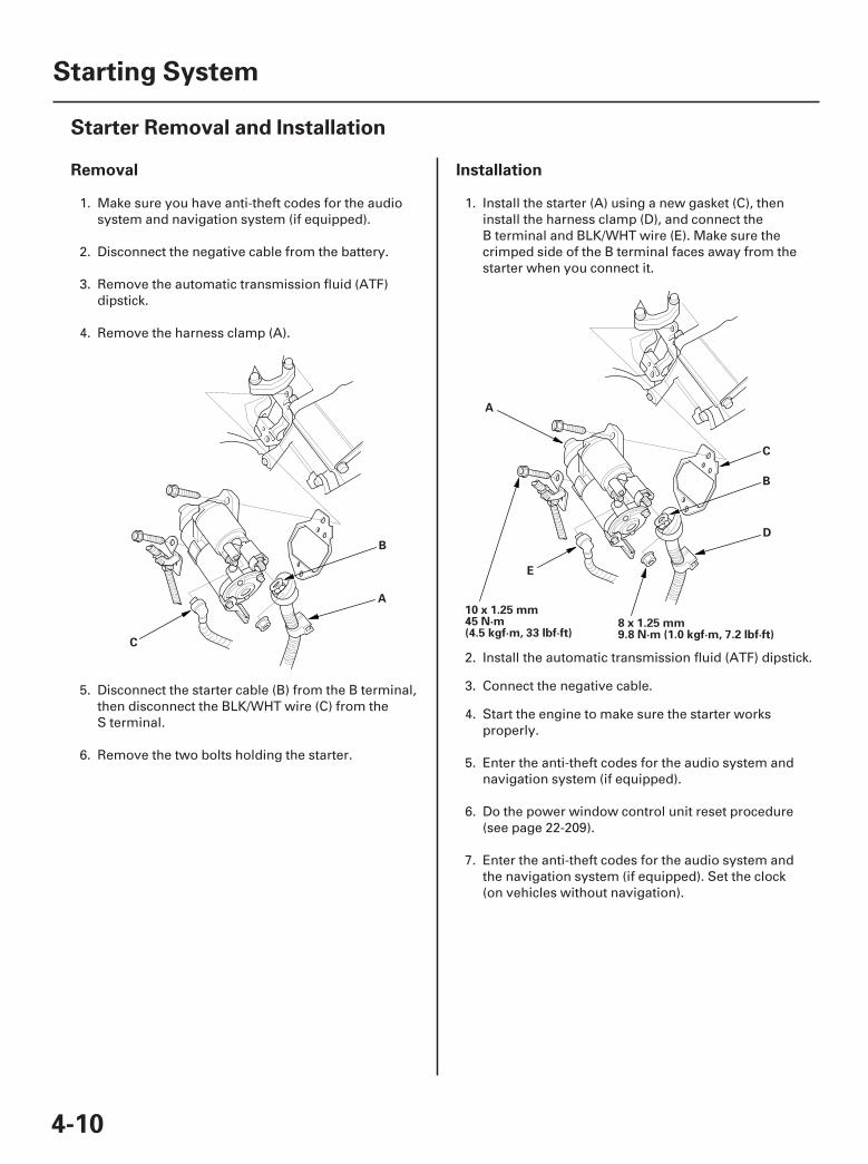
8 x 1.25 mm9.8 N·m (1.0 kgf·m, 7.2 lbf·ft)
10 x 1.25 mm45 N·m(4.5 kgf·m, 33 lbf·ft)
B
A
D
C
E
1. Make sure you have anti-theft codes for the audiosystem and navigation system (if equipped).
2. Disconnect the negative cable from the battery.
3. Remove the automatic transmission fluid (ATF)dipstick.
4. Remove the harness clamp (A).
5. Disconnect the starter cable (B) from the B terminal,then disconnect the BLK/WHT wire (C) from theS terminal.
6. Remove the two bolts holding the starter.
1. Install the starter (A) using a new gasket (C), theninstall the harness clamp (D), and connect theB terminal and BLK/WHT wire (E). Make sure thecrimped side of the B terminal faces away from thestarter when you connect it.
2.
3.
4. Start the engine to make sure the starter worksproperly.
5. Enter the anti-theft codes for the audio system andnavigation system (if equipped).
6. Do the power window control unit reset procedure(see page 22-209).
7. Enter the anti-theft codes for the audio system andthe navigation system (if equipped). Set the clock(on vehicles without navigation).
07/05/09 16:32:49 61SJC020_040_0011
Install the automatic transmission fluid (ATF) dipstick.
Connect the negative cable.
01
SJC8A00A46500056901LAAT00
Disassembly/Reassembly
4-11
Starter Overhaul
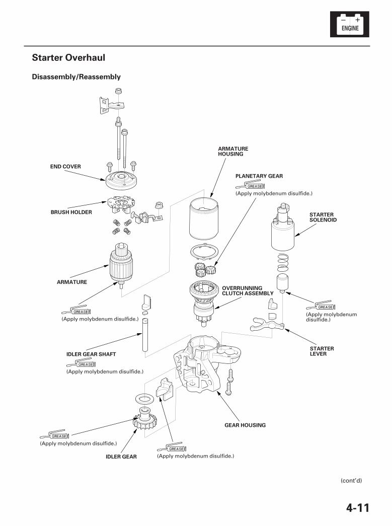
END COVER
BRUSH HOLDER
ARMATURE
ARMATUREHOUSING
PLANETARY GEAR
STARTERSOLENOID
STARTERLEVER
OVERRUNNINGCLUTCH ASSEMBLY
GEAR HOUSING
IDLER GEAR
IDLER GEAR SHAFT
(cont’d)
(Apply molybdenumdisulfide.)(Apply molybdenum disulfide.)
(Apply molybdenum disulfide.)
(Apply molybdenum disulfide.)
(Apply molybdenum disulfide.)
(Apply molybdenum disulfide.)
07/05/09 16:32:49 61SJC020_040_0012
♯ ♯
02
03
04
05
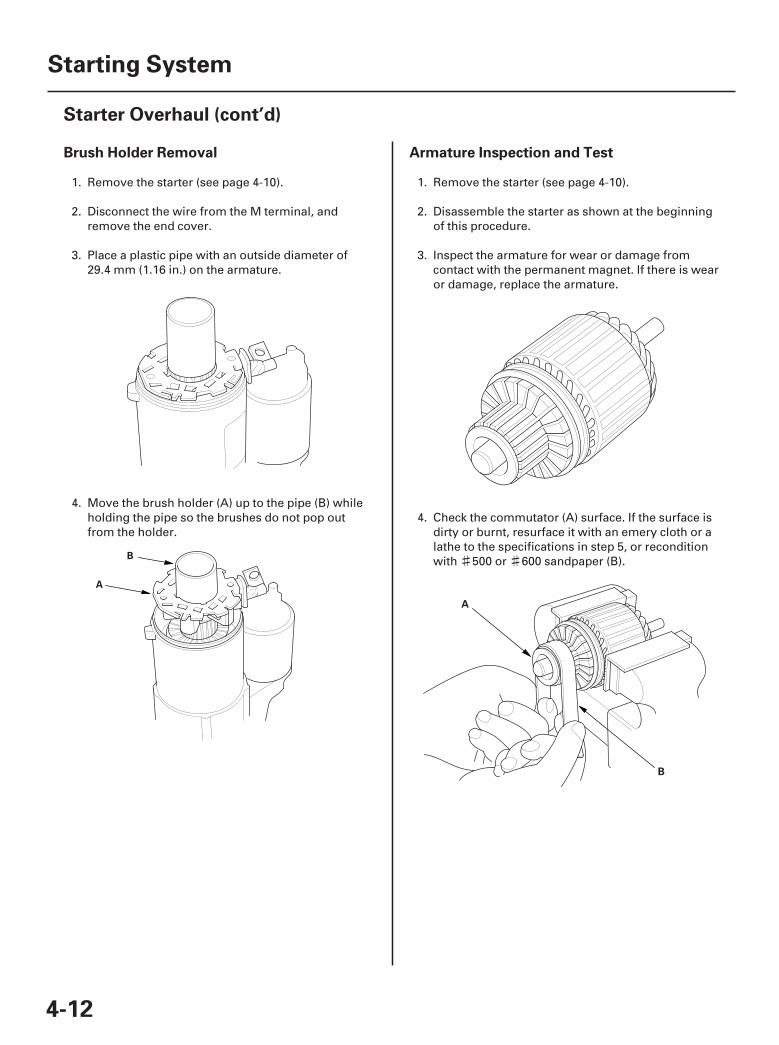
Brush Holder Removal Armature Inspection and Test
4-12
Starting System
Starter Overhaul (cont’d)
B
A
B
A
1. Remove the starter (see page 4-10).
2. Disconnect the wire from the M terminal, andremove the end cover.
3. Place a plastic pipe with an outside diameter of29.4 mm (1.16 in.) on the armature.
4. Move the brush holder (A) up to the pipe (B) whileholding the pipe so the brushes do not pop outfrom the holder.
1. Remove the starter (see page 4-10).
2. Disassemble the starter as shown at the beginningof this procedure.
3. Inspect the armature for wear or damage fromcontact with the permanent magnet. If there is wearor damage, replace the armature.
4. Check the commutator (A) surface. If the surface isdirty or burnt, resurface it with an emery cloth or alathe to the specifications in step 5, or reconditionwith 500 or 600 sandpaper (B).
07/05/09 16:32:50 61SJC020_040_0013
06
07
08
09
- -
- -
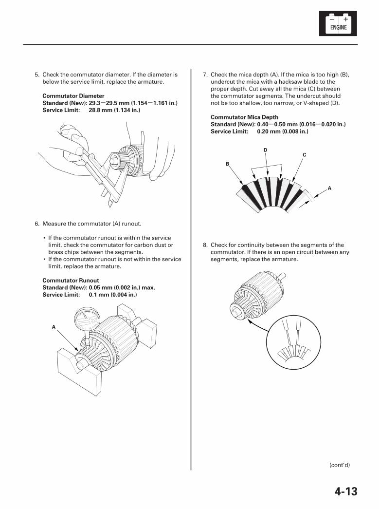
Commutator Diameter
Standard (New): 29.3 29.5 mm (1.154 1.161 in.)
Service Limit: 28.8 mm (1.134 in.)
Commutator Runout
Standard (New): 0.05 mm (0.002 in.) max.
Service Limit: 0.1 mm (0.004 in.)
Commutator Mica Depth
Standard (New): 0.40 0.50 mm (0.016 0.020 in.)
Service Limit: 0.20 mm (0.008 in.)
4-13
A
B
CD
A
5. Check the commutator diameter. If the diameter isbelow the service limit, replace the armature.
6. Measure the commutator (A) runout.
• If the commutator runout is within the servicelimit, check the commutator for carbon dust orbrass chips between the segments.
• If the commutator runout is not within the servicelimit, replace the armature.
7. Check the mica depth (A). If the mica is too high (B),undercut the mica with a hacksaw blade to theproper depth. Cut away all the mica (C) betweenthe commutator segments. The undercut shouldnot be too shallow, too narrow, or V-shaped (D).
8. Check for continuity between the segments of thecommutator. If there is an open circuit between anysegments, replace the armature.
(cont’d)
07/05/09 16:32:50 61SJC020_040_0014
+-
10
11
12
13
- -
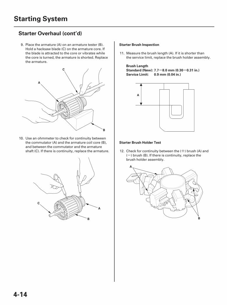
Starter Brush Inspection
Brush Length
Standard (New): 7.7 8.0 mm (0.30 0.31 in.)
Service Limit: 0.9 mm (0.04 in.)
Starter Brush Holder Test
4-14
Starting System
Starter Overhaul (cont’d)
C
A
B
B
C
A
A
B
A
9. Place the armature (A) on an armature tester (B).Hold a hacksaw blade (C) on the armature core. Ifthe blade is attracted to the core or vibrates whilethe core is turned, the armature is shorted. Replacethe armature.
10. Use an ohmmeter to check for continuity betweenthe commutator (A) and the armature coil core (B),and between the commutator and the armatureshaft (C). If there is continuity, replace the armature.
11. Measure the brush length (A). If it is shorter thanthe service limit, replace the brush holder assembly.
12. Check for continuity between the ( ) brush (A) and( ) brush (B). If there is continuity, replace thebrush holder assembly.
07/05/09 16:32:51 61SJC020_040_0015
14
15
16
17
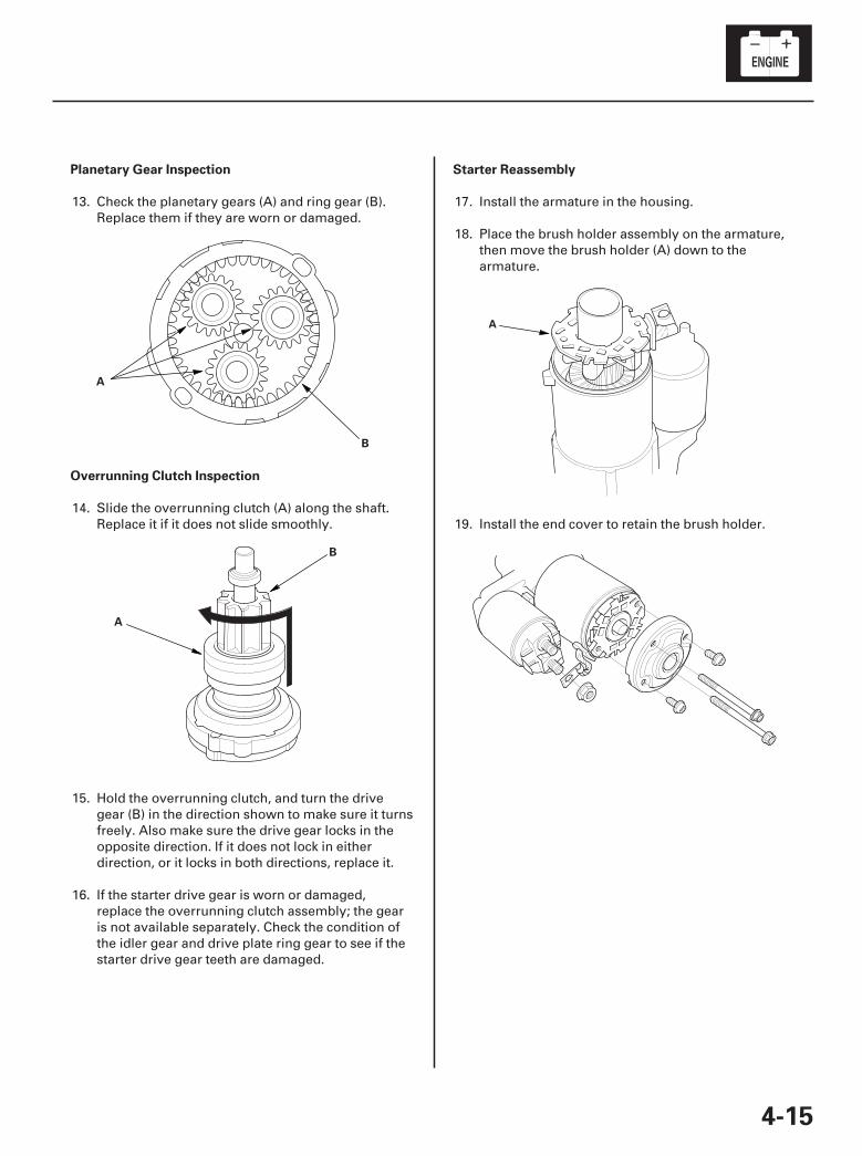
Planetary Gear Inspection
Overrunning Clutch Inspection
Starter Reassembly
4-15
A
B
A
B
A
13. Check the planetary gears (A) and ring gear (B).Replace them if they are worn or damaged.
14. Slide the overrunning clutch (A) along the shaft.Replace it if it does not slide smoothly.
15. Hold the overrunning clutch, and turn the drivegear (B) in the direction shown to make sure it turnsfreely. Also make sure the drive gear locks in theopposite direction. If it does not lock in eitherdirection, or it locks in both directions, replace it.
16. If the starter drive gear is worn or damaged,replace the overrunning clutch assembly; the gearis not available separately. Check the condition ofthe idler gear and drive plate ring gear to see if thestarter drive gear teeth are damaged.
17. Install the armature in the housing.
18. Place the brush holder assembly on the armature,then move the brush holder (A) down to thearmature.
19. Install the end cover to retain the brush holder.
07/05/09 16:32:51 61SJC020_040_0016
*01
*02
SJC8A00A26100000000DAAT00
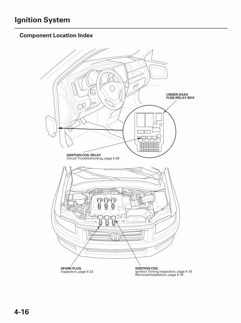
4-16
Ignition System
Component Location Index
UNDER-DASHFUSE/RELAY BOX
IGNITION COIL RELAY
IGNITION COILSPARK PLUG
Circuit Troubleshooting, page 4-20
Ignition Timing Inspection, page 4-18Removal/Installation, page 4-19
Inspection, page 4-22
07/05/09 16:32:52 61SJC020_040_0017
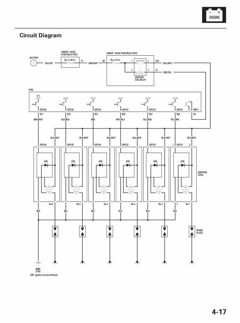
01
SJC8A00A26100000000EAAT00
--
4-17
Circuit Diagram
IGPLS6 IGPLS5 IGPLS4 IGPLS3 IGPLS2 IGPLS1 MRLY
X1
X32B2
4
1
3
2C1 No.2 (15 A)
UNDER DASH FUSE/RELAY BOX
BLK/YEL
2
1 3
G102
IGPLS1IGPLS2IGPLS3IGPLS4IGPLS5IGPLS6
YEL/GRNBLU/RED
B26
BLK/WHT
BLK
No.1
ICM
WHT/BLU
B27
BLK/WHT
BLK
No.2
ICM
BRN
B20
BLK/WHT
BLK
No.3
ICM
BLK/RED
B21
BLK/WHT
BLK
No.4
ICMICM
No.5
GRN/WHT
ICM : Ignition Conotrol Module
BLK BLK
BLK/WHT BLK/WHT
5 V
PCM
B11 B10 A6
BLK/WHT
No.17 (40 A)
RED/YEL
No.6
ICM
BRN/WHT
BATTERY
G101G101
IGNITIONCOIL RELAY
SPARKPLUGS
IGINITIONCOILS
UNDER HOODFUSE/RELAY BOX
07/05/09 16:32:53 61SJC020_040_0018
01
02
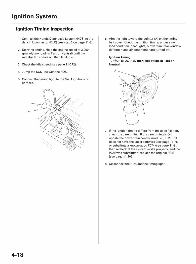
SJC8A00A26100000000MAAT00
±Ignition Timing
10 ° 2 ° BTDC (RED mark (B)) at idle in Park or
Neutral
4-18
Ignition System
Ignition Timing Inspection
A
B
1. Connect the Honda Diagnostic System (HDS) to thedata link connector (DLC) (see step 2 on page 11-3).
2. Start the engine. Hold the engine speed at 3,000rpm with no load (in Park or Neutral) until theradiator fan comes on, then let it idle.
3. Check the idle speed (see page 11-272).
4. Jump the SCS line with the HDS.
5. Connect the timing light to the No. 1 ignition coilharness.
6. Aim the light toward the pointer (A) on the timingbelt cover. Check the ignition timing under a noload condition (headlights, blower fan, rear windowdefogger, and air conditioner are turned off).
7. If the ignition timing differs from the specification,check the cam timing. If the cam timing is OK,update the powertrain control module (PCM). If itdoes not have the latest software (see page 11-7),or substitute a known-good PCM (see page 11-8),then recheck. If the system works properly, and thePCM was substituted, replace the original PCM(see page 11-205).
8. Disconnect the HDS and the timing light.
07/05/09 16:32:53 61SJC020_040_0019
01
02
03
SJC8A00A26100034101KDAT00
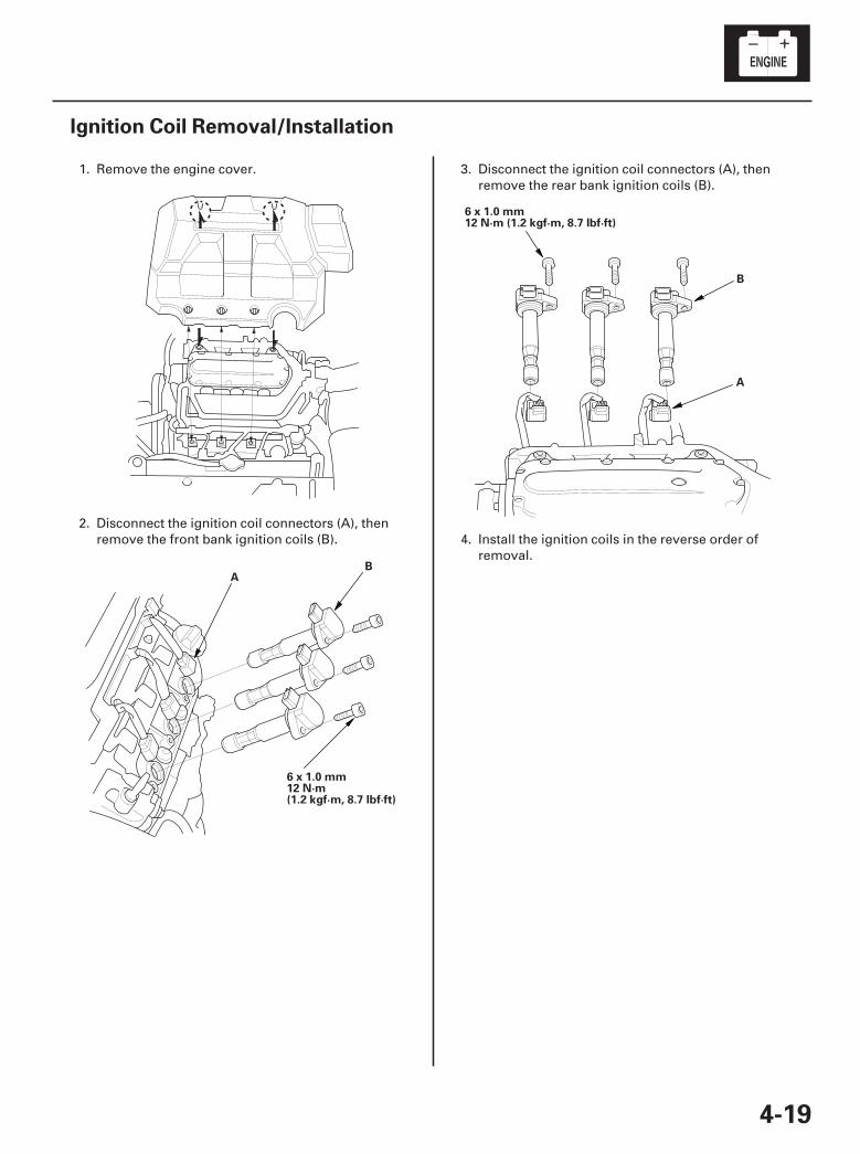
4-19
Ignition Coil Removal/Installation
6 x 1.0 mm12 N·m(1.2 kgf·m, 8.7 lbf·ft)
AB
6 x 1.0 mm12 N·m (1.2 kgf·m, 8.7 lbf·ft)
B
A
1. Remove the engine cover.
2. Disconnect the ignition coil connectors (A), thenremove the front bank ignition coils (B).
3. Disconnect the ignition coil connectors (A), thenremove the rear bank ignition coils (B).
4. Install the ignition coils in the reverse order ofremoval.
07/05/09 16:32:54 61SJC020_040_0020
01
02
SJC8A00A26100034112FAAT00
-
-
-
-
-
-
-
-
YES
NO
YES
NO
YES
NO
YES
NO
4-20
Ignition System
Ignition Coil Relay Circuit Troubleshooting
IGNITION COIL RELAY 4P SOCKET
IGNITION COIL RELAY 4P SOCKET
No.1 IGNITION COIL 3P CONNECTOR
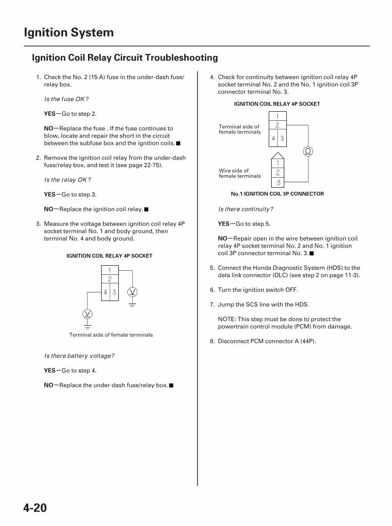
1. Check the No. 2 (15 A) fuse in the under-dash fuse/relay box.
Go to step 2.
Replace the fuse . If the fuse continues toblow, locate and repair the short in the circuitbetween the subfuse box and the ignition coils.
2. Remove the ignition coil relay from the under-dashfuse/relay box, and test it (see page 22-75).
Go to step 3.
Replace the ignition coil relay.
3. Measure the voltage between ignition coil relay 4Psocket terminal No. 1 and body ground, thenterminal No. 4 and body ground.
Go to step 4.
Replace the under-dash fuse/relay box.
4. Check for continuity between ignition coil relay 4Psocket terminal No. 2 and the No. 1 ignition coil 3Pconnector terminal No. 3.
Go to step 5.
Repair open in the wire between ignition coilrelay 4P socket terminal No. 2 and No. 1 ignitioncoil 3P connector terminal No. 3.
5. Connect the Honda Diagnostic System (HDS) to thedata link connector (DLC) (see step 2 on page 11-3).
6. Turn the ignition switch OFF.
7. Jump the SCS line with the HDS.
NOTE: This step must be done to protect thepowertrain control module (PCM) from damage.
8. Disconnect PCM connector A (44P).Terminal side of female terminals
Terminal side offemale terminals
Wire side offemale terminals
Is the fuse OK ?
Is the relay OK ?
Is there battery voltage?
Is there continuity?
07/05/09 16:33:19 61SJC020_040_0021
0304
-
-
-
-
YES
NO
YES
NO
4-21
IGNITION COIL RELAY 4P SOCKET IGNITION COIL RELAY 4P SOCKET
MRLY (RED/YEL)
PCM CONNECTOR A (44P)
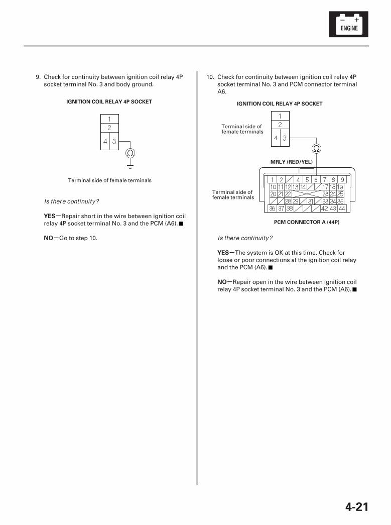
9. Check for continuity between ignition coil relay 4Psocket terminal No. 3 and body ground.
Repair short in the wire between ignition coilrelay 4P socket terminal No. 3 and the PCM (A6).
Go to step 10.
10. Check for continuity between ignition coil relay 4Psocket terminal No. 3 and PCM connector terminalA6.
The system is OK at this time. Check forloose or poor connections at the ignition coil relayand the PCM (A6).
Repair open in the wire between ignition coilrelay 4P socket terminal No. 3 and the PCM (A6).
Terminal side of female terminals
Terminal side offemale terminals
Terminal side offemale terminals
Is there continuity?
Is there continuity?
07/05/09 16:33:20 61SJC020_040_0022
01
02
03
SJC8A00A26100055901MAAT00
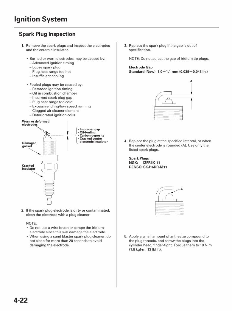
- -Electrode Gap
Standard (New): 1.0 1.1 mm (0.039 0.043 in.)
Spark Plugs
NGK: IZFR5K-11
DENSO: SKJ16DR-M11
4-22
Ignition System
Spark Plug Inspection
• Improper gap• Oil-fouling• Carbon deposits• Cracked centerelectrode insulator
Worn or deformedelectrodes
Damagedgasket
Crackedinsulator
A
A
1. Remove the spark plugs and inspect the electrodesand the ceramic insulator.
• Burned or worn electrodes may be caused by:– Advanced ignition timing– Loose spark plug– Plug heat range too hot– Insufficient cooling
• Fouled plugs may be caused by:– Retarded ignition timing– Oil in combustion chamber– Incorrect spark plug gap– Plug heat range too cold– Excessive idling/low speed running– Clogged air cleaner element– Deteriorated ignition coils
2. If the spark plug electrode is dirty or contaminated,clean the electrode with a plug cleaner.
NOTE:• Do not use a wire brush or scrape the iridium
electrode since this will damage the electrode.• When using a sand blaster spark plug cleaner, do
not clean for more than 20 seconds to avoiddamaging the electrode.
3. Replace the spark plug if the gap is out ofspecification.
NOTE: Do not adjust the gap of iridium tip plugs.
4. Replace the plug at the specified interval, or whenthe center electrode is rounded (A). Use only thelisted spark plugs.
5. Apply a small amount of anti-seize compound tothe plug threads, and screw the plugs into thecylinder head, finger-tight. Torque them to 18 N·m(1.8 kgf·m, 13 lbf·ft).
07/05/09 16:33:20 61SJC020_040_0023
*01
SJC8A00A14100000000DAAT00
4-23
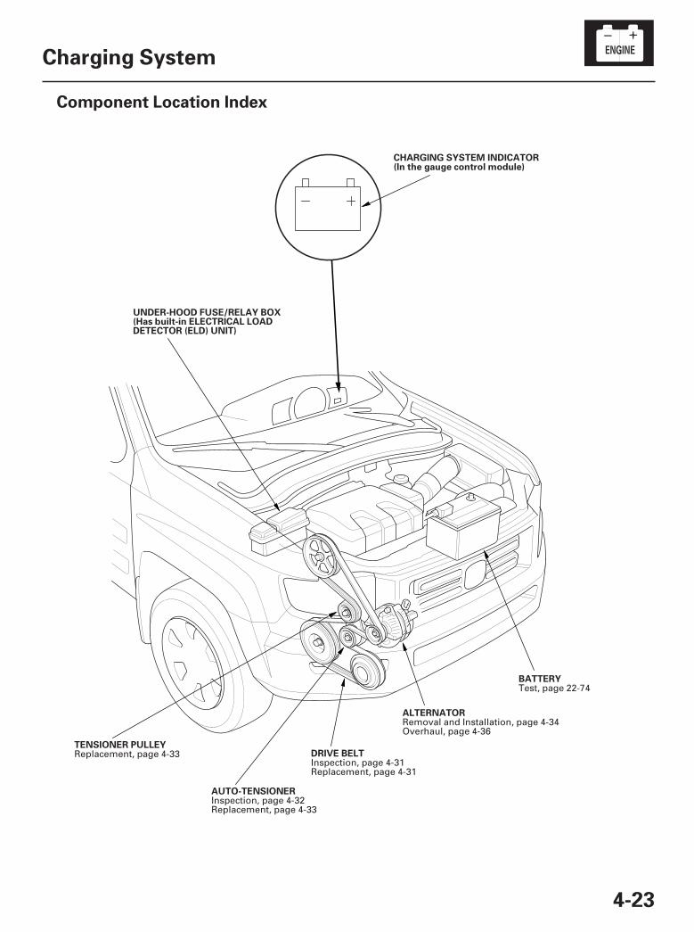
Charging System
Component Location Index
BATTERY
DRIVE BELTTENSIONER PULLEY
CHARGING SYSTEM INDICATOR(In the gauge control module)
UNDER-HOOD FUSE/RELAY BOX(Has built-in ELECTRICAL LOADDETECTOR (ELD) UNIT)
ALTERNATOR
AUTO-TENSIONER
Test, page 22-74
Inspection, page 4-31Replacement, page 4-31
Replacement, page 4-33
Removal and Installation, page 4-34Overhaul, page 4-36
Inspection, page 4-32Replacement, page 4-33
07/05/09 16:33:22 61SJC020_040_0024
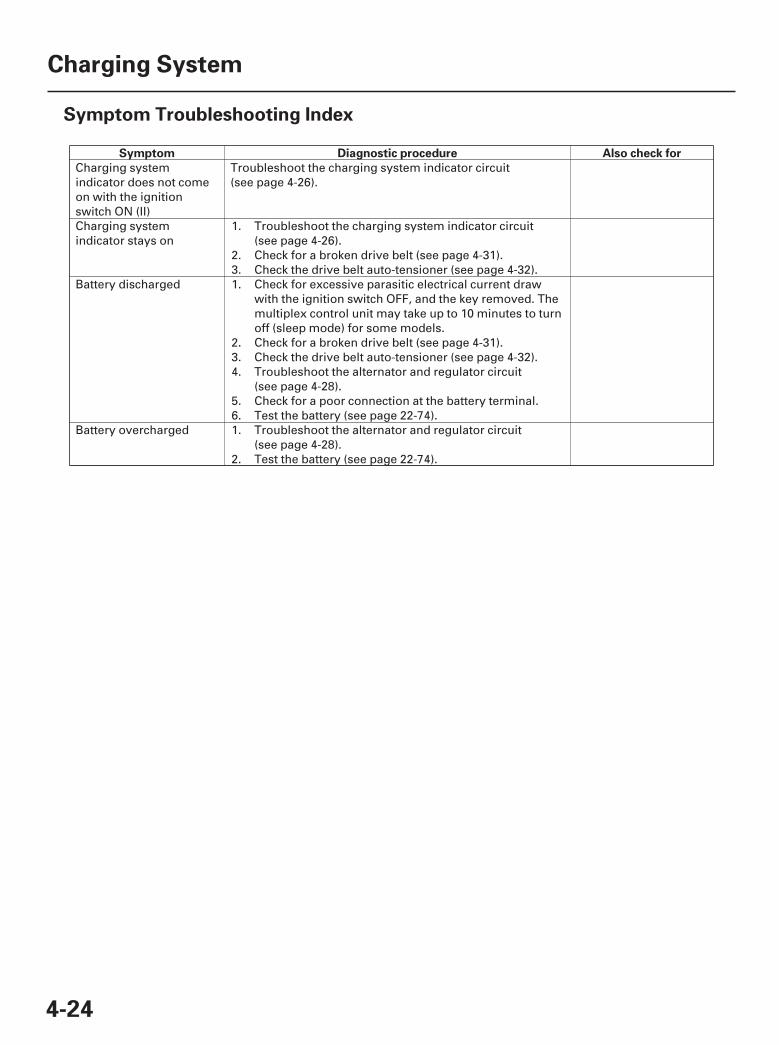
SJC8A00A14100000000HBAT01
Symptom Diagnostic procedure Also check for
4-24
Charging System
Symptom Troubleshooting Index
Charging systemindicator does not comeon with the ignitionswitch ON (II)
Troubleshoot the charging system indicator circuit(see page 4-26).
Charging systemindicator stays on
1.
2.3.
Troubleshoot the charging system indicator circuit(see page 4-26).Check for a broken drive belt (see page 4-31).Check the drive belt auto-tensioner (see page 4-32).
Battery discharged 1.
2.3.4.
5.6.
Check for excessive parasitic electrical current drawwith the ignition switch OFF, and the key removed. Themultiplex control unit may take up to 10 minutes to turnoff (sleep mode) for some models.Check for a broken drive belt (see page 4-31).Check the drive belt auto-tensioner (see page 4-32).Troubleshoot the alternator and regulator circuit(see page 4-28).Check for a poor connection at the battery terminal.Test the battery (see page 22-74).
Battery overcharged 1.
2.
Troubleshoot the alternator and regulator circuit(see page 4-28).Test the battery (see page 22-74).
07/05/09 16:33:22 61SJC020_040_0025
*01
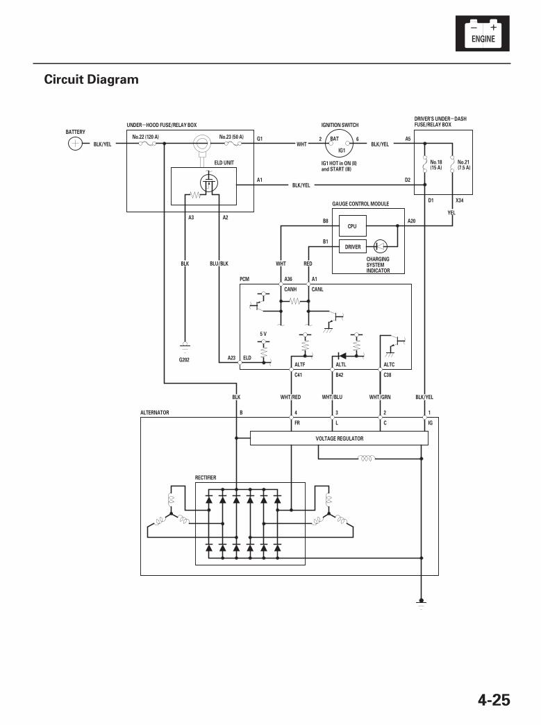
SJC8A00A14100000000EAAT00
--
4-25
Circuit Diagram
ELD
ALTF ALTL ALTC
CANLCANH
B1
B8 A20
X34D1
A2A3
A1
G1
D2
A5BLK/YEL BLK/YELWHT
REDWHT
5 V
GAUGE CONTROL MODULE
A1A36
DRIVER
CPU
WHT/BLU
3
B42
L IG
1ALTERNATOR
FR C
YEL
(7.5 A)No.21ELD UNIT
A23
IGNITION SWITCH
BAT
IG1
PCM
C41 C38
BLK/YEL
BLK/YEL
No.23 (50 A)
BLK
RECTIFIER
No.18(15 A)
BATTERY
VOLTAGE REGULATOR
24B
BLK
G202
UNDER HOOD FUSE/RELAY BOX
No.22 (120 A)
BLU/BLK
WHT/RED WHT/GRN
DRIVER’S UNDER DASHFUSE/RELAY BOX
IG1 HOT in ON (II)and START (III)
CHARGINGSYSTEMINDICATOR
2 6
07/05/09 16:33:22 61SJC020_040_0026
01
SJC8A00A14100016802FAAT00
-
-
-
-
-
-
-
-
-
-
YES
NO
YES
NO
YES
NO
YES
NO
YES
NO
4-26
Charging System
Charging System Indicator Circuit Troubleshooting
PCM CONNECTOR B (44P)
ALT L(WHT/BLU)
1. Turn the ignition switch ON (II).
Go to step 2.
Go to step 12.
2. Start the engine. Hold the engine speed at2,000 rpm for 1 minute.
Charging system indicator circuit is OK. Goto the alternator and regulator circuittroubleshooting (see page 4-28).
Go to step 3.
3. Do the gauge control module self-diagnosticfunction procedure (see page 22-244).
Go to step 4.
Replace the gauge control module (see page22-263).
4. Turn the ignition switch OFF.
5. Disconnect the alternator 4P connector.
6. Turn the ignition switch ON (II).
NOTE: The charging system indicator may come onand then go off.
Replace the alternator (see page 4-34) orrepair the alternator (see page 4-36).
Go to step 7.
7. Turn the ignition switch OFF.
8. Connect the Honda Diagnostic System (HDS) to thedata link connector (DLC).
9. Jump the SCS line with the HDS.
NOTE: This step must be done to protect thepowertrain control module (PCM) from damage.
10. Disconnect PCM connector B (44P).
11. Check for continuity between PCM connectorterminal B42 and body ground.
Repair short in the wire between thealternator and the PCM.
Update the PCM if it does not have the latestsoftware (see page 11-7), or substitute a known-good PCM (see page 11-8), then recheck. If thesymptom/indication goes away with a known-goodPCM, replace the original PCM (see page 11-205).
Terminal side of female terminals
Does the charging system indicator come on?
Does the charging system indicator go of f?
Does the charging system indicator f lash?
Does the charging system indicator go of f?
Is there continuity?
07/05/09 16:33:22 61SJC020_040_0027
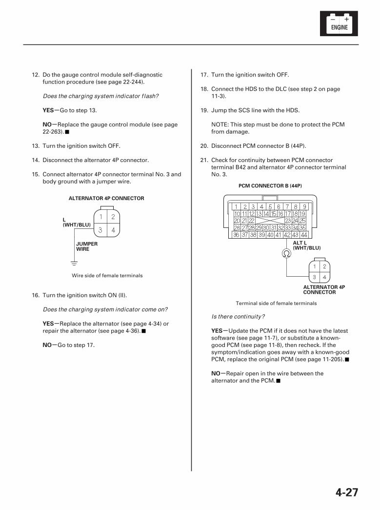
02*01
-
-
-
-
-
-
YES
NO
YES
NO
YES
NO
4-27
ALTERNATOR 4P CONNECTOR
L(WHT/BLU)
JUMPERWIRE
PCM CONNECTOR B (44P)
ALT L(WHT/BLU)
ALTERNATOR 4PCONNECTOR
12. Do the gauge control module self-diagnosticfunction procedure (see page 22-244).
Go to step 13.
Replace the gauge control module (see page22-263).
13. Turn the ignition switch OFF.
14. Disconnect the alternator 4P connector.
15. Connect alternator 4P connector terminal No. 3 andbody ground with a jumper wire.
16. Turn the ignition switch ON (II).
Replace the alternator (see page 4-34) orrepair the alternator (see page 4-36).
Go to step 17.
17. Turn the ignition switch OFF.
18. Connect the HDS to the DLC (see step 2 on page11-3).
19. Jump the SCS line with the HDS.
NOTE: This step must be done to protect the PCMfrom damage.
20. Disconnect PCM connector B (44P).
21. Check for continuity between PCM connectorterminal B42 and alternator 4P connector terminalNo. 3.
Update the PCM if it does not have the latestsoftware (see page 11-7), or substitute a known-good PCM (see page 11-8), then recheck. If thesymptom/indication goes away with a known-goodPCM, replace the original PCM (see page 11-205).
Repair open in the wire between thealternator and the PCM.
Wire side of female terminals
Terminal side of female terminals
Does the charging system indicator f lash?
Does the charging system indicator come on?Is there continuity?
07/05/09 16:33:23 61SJC020_040_0028
-
01
SJC8A00A14100012903FAAT00
-
-
-
-
-
-
YES
NO
YES
NO
YES
NO
4-28
Charging System
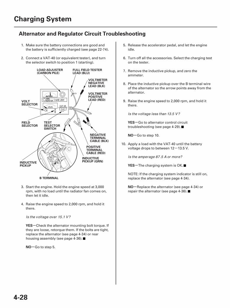
Alternator and Regulator Circuit Troubleshooting
LOAD ADJUSTER(CARBON PILE)
VOLTSELECTOR
FIELDSELECTOR
TESTSELECTORSWITCH
INDUCTIVEPICKUP
B TERMINAL
INDUCTIVEPICKUP (GRN)
POSITIVETERMINALCABLE (RED)
NEGATIVETERMINALCABLE (BLK)
VOLTMETERPOSITIVELEAD (RED)
VOLTMETERNEGATIVELEAD (BLK)
FULL FIELD TESTERLEAD (BLU)
1. Make sure the battery connections are good andthe battery is sufficiently charged (see page 22-74).
2. Connect a VAT-40 (or equivalent tester), and turnthe selector switch to position 1 (starting).
3. Start the engine. Hold the engine speed at 3,000rpm, with no load until the radiator fan comes on,then let it idle.
4. Raise the engine speed to 2,000 rpm, and hold itthere.
Check the alternator mounting bolt torque. Ifthey are loose, retorque them. If the bolts are tight,replace the alternator (see page 4-34) or rearhousing assembly (see page 4-36).
Go to step 5.
5. Release the accelerator pedal, and let the engineidle.
6. Turn off all the accessories. Select the charging teston the tester.
7. Remove the inductive pickup, and zero theammeter.
8. Place the inductive pickup over the B terminal wireof the alternator so the arrow points away from thealternator.
9. Raise the engine speed to 2,000 rpm, and hold itthere.
Go to alternator control circuittroubleshooting (see page 4-29).
Go to step 10.
10. Apply a load with the VAT-40 until the batteryvoltage drops to between 12 13.5 V.
The charging system is OK.
NOTE: If the charging system indicator is still on,replace the alternator (see page 4-34).
Replace the alternator (see page 4-34) orrepair the alternator (see page 4-36).
Is the voltage over 15.1 V?
Is the voltage less than 13.5 V?
Is the amperage 87.5 A or more?
07/05/09 16:33:23 61SJC020_040_0029
01
02
SJC8A00A14100012905FAAT00
-
-
-
-
YES
NO
YES
NO
4-29
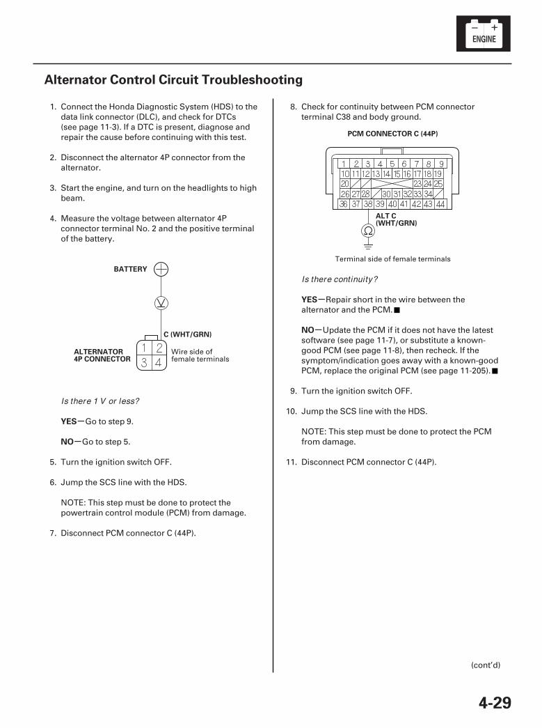
Alternator Control Circuit Troubleshooting
BATTERY
ALTERNATOR4P CONNECTOR
C (WHT/GRN)
PCM CONNECTOR C (44P)
ALT C(WHT/GRN)
1. Connect the Honda Diagnostic System (HDS) to thedata link connector (DLC), and check for DTCs(see page 11-3). If a DTC is present, diagnose andrepair the cause before continuing with this test.
2. Disconnect the alternator 4P connector from thealternator.
3. Start the engine, and turn on the headlights to highbeam.
4. Measure the voltage between alternator 4Pconnector terminal No. 2 and the positive terminalof the battery.
Go to step 9.
Go to step 5.
5. Turn the ignition switch OFF.
6. Jump the SCS line with the HDS.
NOTE: This step must be done to protect thepowertrain control module (PCM) from damage.
7. Disconnect PCM connector C (44P).
8. Check for continuity between PCM connectorterminal C38 and body ground.
Repair short in the wire between thealternator and the PCM.
Update the PCM if it does not have the latestsoftware (see page 11-7), or substitute a known-good PCM (see page 11-8), then recheck. If thesymptom/indication goes away with a known-goodPCM, replace the original PCM (see page 11-205).
9. Turn the ignition switch OFF.
10. Jump the SCS line with the HDS.
NOTE: This step must be done to protect the PCMfrom damage.
11. Disconnect PCM connector C (44P).
(cont’d)
Wire side offemale terminals
Terminal side of female terminals
Is there 1 V or less?
Is there continuity?
07/05/09 16:33:23 61SJC020_040_0030
03
-
-
YES
NO
4-30
Charging System
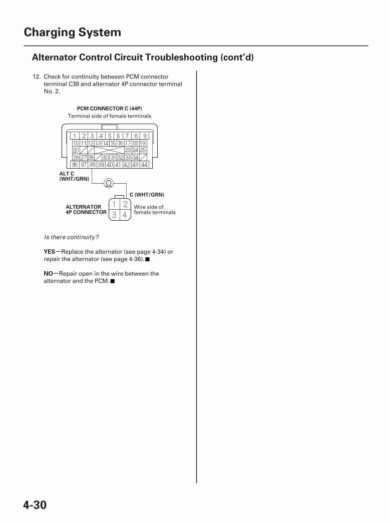
Alternator Control Circuit Troubleshooting (cont’d)
PCM CONNECTOR C (44P)
C (WHT/GRN)
ALTERNATOR4P CONNECTOR
ALT C(WHT/GRN)
12. Check for continuity between PCM connectorterminal C38 and alternator 4P connector terminalNo. 2.
Replace the alternator (see page 4-34) orrepair the alternator (see page 4-36).
Repair open in the wire between thealternator and the PCM.
Terminal side of female terminals
Wire side offemale terminals
Is there continuity?
07/05/09 16:33:24 61SJC020_040_0031
01
SJC8A00A14100022201MAAT01
01
SJC8A00A14100022201KBAT02
4-314-31
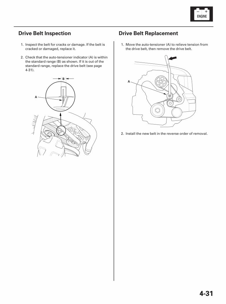
Drive Belt Inspection Drive Belt Replacement
A
BA
1. Inspect the belt for cracks or damage. If the belt iscracked or damaged, replace it.
2. Check that the auto-tensioner indicator (A) is withinthe standard range (B) as shown. If it is out of thestandard range, replace the drive belt (see page4-31).
1. Move the auto-tensioner (A) to relieve tension fromthe drive belt, then remove the drive belt.
2. Install the new belt in the reverse order of removal.
07/05/09 16:33:24 61SJC020_040_0032
01
02
03
04
SJC8A00A14100022205MAAT00
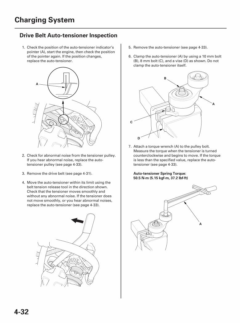
Auto-tensioner Spring Torque:
50.5 N·m (5.15 kgf·m, 37.2 lbf·ft)
4-32
Charging System
Drive Belt Auto-tensioner Inspection
A
B
A
D
C
A
1. Check the position of the auto-tensioner indicator’spointer (A), start the engine, then check the positionof the pointer again. If the position changes,replace the auto-tensioner.
2. Check for abnormal noise from the tensioner pulley.If you hear abnormal noise, replace the auto-tensioner pulley (see page 4-33).
3. Remove the drive belt (see page 4-31).
4. Move the auto-tensioner within its limit using thebelt tension release tool in the direction shown.Check that the tensioner moves smoothly andwithout any abnormal noise. If the tensioner doesnot move smoothly, or you hear abnormal noises,replace the auto-tensioner (see page 4-33).
5. Remove the auto-tensioner (see page 4-33).
6. Clamp the auto-tensioner (A) by using a 10 mm bolt(B), 8 mm bolt (C), and a vise (D) as shown. Do notclamp the auto-tensioner itself.
7. Attach a torque wrench (A) to the pulley bolt.Measure the torque when the tensioner is turnedcounterclockwise and begins to move. If the torqueis less than the specified value, replace the auto-tensioner (see page 4-33).
07/05/09 16:33:24 61SJC020_040_0033
01
SJC8A00A14100022205KBAT01
01
SJC8A00A14100022208KBAT10
4-334-33
Drive Belt Auto-tensionerReplacement
Tensioner Pulley Replacement
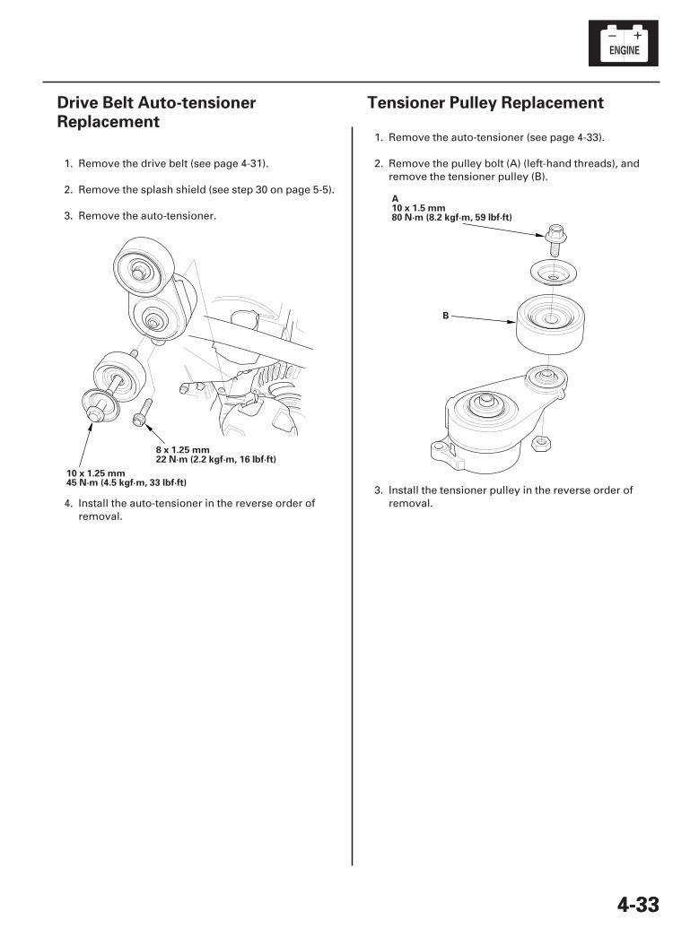
10 x 1.25 mm45 N·m (4.5 kgf·m, 33 lbf·ft)
8 x 1.25 mm22 N·m (2.2 kgf·m, 16 lbf·ft)
A10 x 1.5 mm80 N·m (8.2 kgf·m, 59 lbf·ft)
B
1. Remove the drive belt (see page 4-31).
2. Remove the splash shield (see step 30 on page 5-5).
3. Remove the auto-tensioner.
4. Install the auto-tensioner in the reverse order ofremoval.
1. Remove the auto-tensioner (see page 4-33).
2. Remove the pulley bolt (A) (left-hand threads), andremove the tensioner pulley (B).
3. Install the tensioner pulley in the reverse order ofremoval.
07/05/09 16:33:25 61SJC020_040_0034
01
02
SJC8A00A14100012901KDAT20
Removal
4-34
Charging System
Alternator Removal and Installation
A B
C
D
E
A B
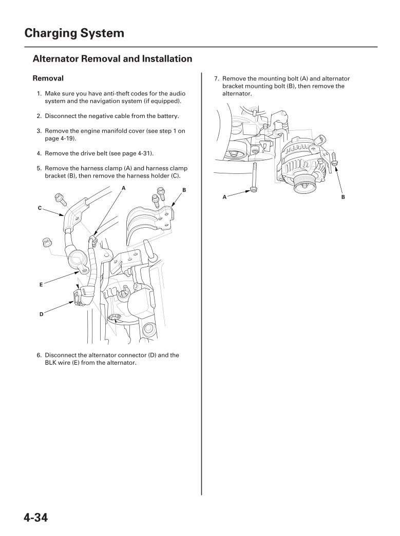
1. Make sure you have anti-theft codes for the audiosystem and the navigation system (if equipped).
2. Disconnect the negative cable from the battery.
3. Remove the engine manifold cover (see step 1 onpage 4-19).
4. Remove the drive belt (see page 4-31).
5. Remove the harness clamp (A) and harness clampbracket (B), then remove the harness holder (C).
6. Disconnect the alternator connector (D) and theBLK wire (E) from the alternator.
7. Remove the mounting bolt (A) and alternatorbracket mounting bolt (B), then remove thealternator.
07/05/09 16:33:25 61SJC020_040_0035
01
04
Installation
4-35
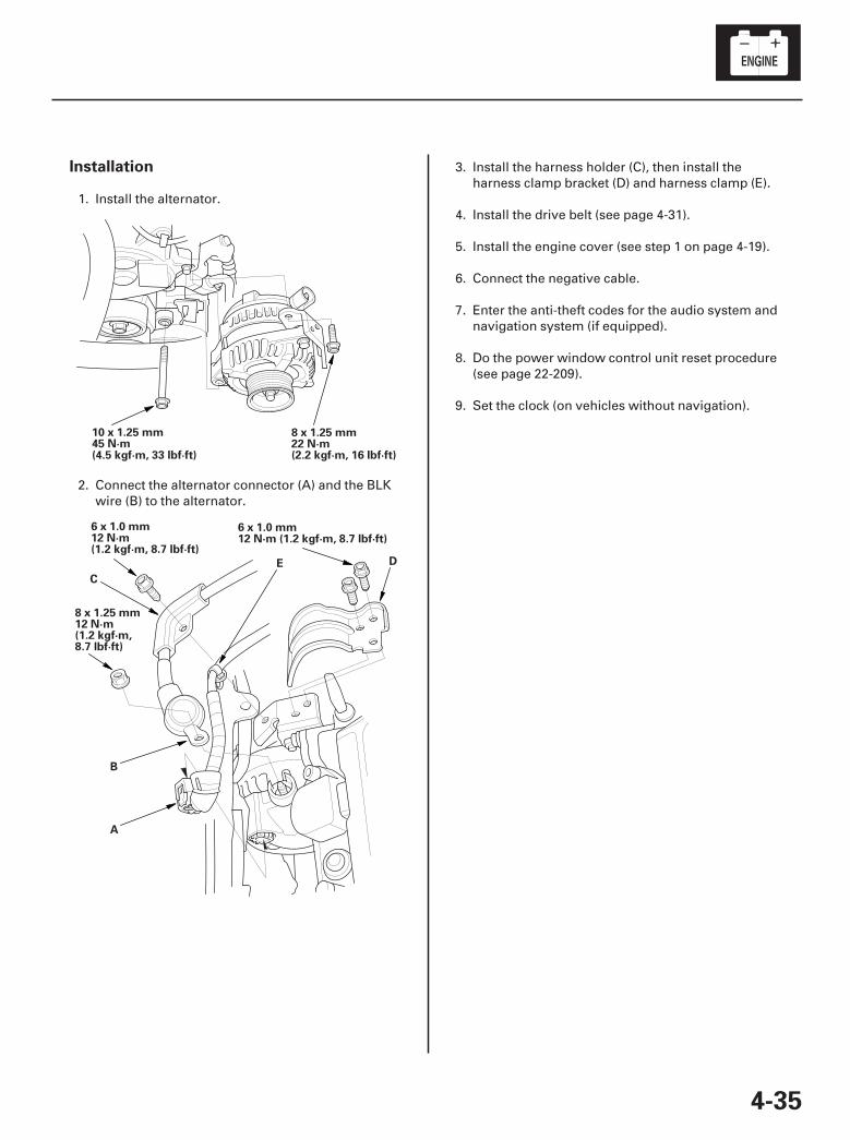
8 x 1.25 mm22 N·m(2.2 kgf·m, 16 lbf·ft)
10 x 1.25 mm45 N·m(4.5 kgf·m, 33 lbf·ft)
8 x 1.25 mm12 N·m(1.2 kgf·m,8.7 lbf·ft)
6 x 1.0 mm12 N·m (1.2 kgf·m, 8.7 lbf·ft)
E D
6 x 1.0 mm12 N·m(1.2 kgf·m, 8.7 lbf·ft)
C
B
A
1. Install the alternator.
2. Connect the alternator connector (A) and the BLKwire (B) to the alternator.
3. Install the harness holder (C), then install theharness clamp bracket (D) and harness clamp (E).
4. Install the drive belt (see page 4-31).
5. Install the engine cover (see step 1 on page 4-19).
6. Connect the negative cable.
7. Enter the anti-theft codes for the audio system andnavigation system (if equipped).
8. Do the power window control unit reset procedure(see page 22-209).
9. Set the clock (on vehicles without navigation).
07/05/09 16:33:26 61SJC020_040_0036
01
SJC8A00A14100012901LAAT00
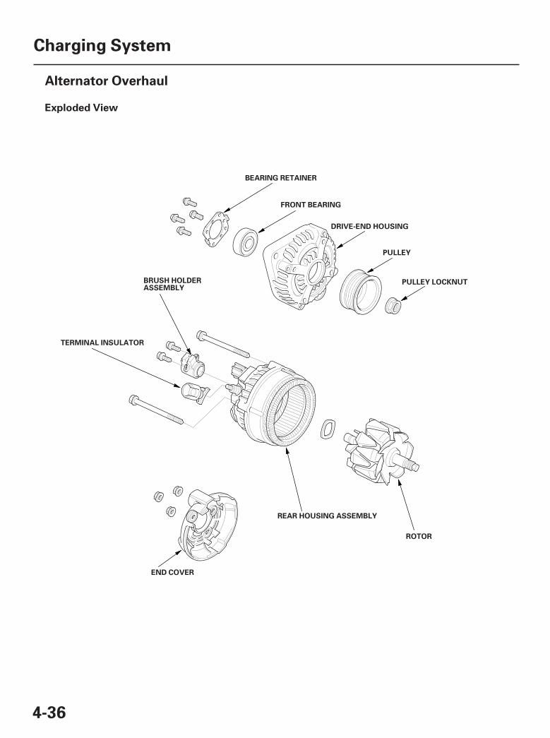
Exploded View
4-36
Charging System
Alternator Overhaul
ROTOR
BEARING RETAINER
FRONT BEARING
DRIVE-END HOUSING
PULLEY
PULLEY LOCKNUT
REAR HOUSING ASSEMBLY
BRUSH HOLDERASSEMBLY
END COVER
TERMINAL INSULATOR
07/05/09 16:33:26 61SJC020_040_0037
02
03
04
05
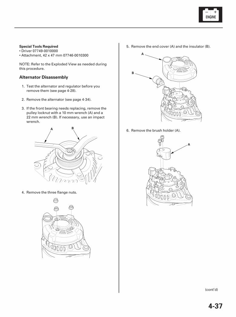
Special Tools Required
Alternator Disassembly
4-37
A B
A
B
A
• Driver 07749-0010000• Attachment, 42 x 47 mm 07746-0010300
NOTE: Refer to the Exploded View as needed duringthis procedure.
1. Test the alternator and regulator before youremove them (see page 4-28).
2. Remove the alternator (see page 4-34).
3. If the front bearing needs replacing, remove thepulley locknut with a 10 mm wrench (A) and a22 mm wrench (B). If necessary, use an impactwrench.
4. Remove the three flange nuts.
5. Remove the end cover (A) and the insulator (B).
6. Remove the brush holder (A).
(cont’d)
07/05/09 16:33:27 61SJC020_040_0038
06
07
08
09
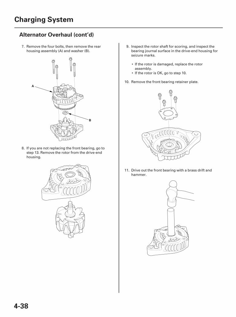
4-38
Charging System
Alternator Overhaul (cont’d)
A
B
7. Remove the four bolts, then remove the rearhousing assembly (A) and washer (B).
8. If you are not replacing the front bearing, go tostep 13. Remove the rotor from the drive-endhousing.
9. Inspect the rotor shaft for scoring, and inspect thebearing journal surface in the drive-end housing forseizure marks.
• If the rotor is damaged, replace the rotorassembly.
• If the rotor is OK, go to step 10.
10. Remove the front bearing retainer plate.
11. Drive out the front bearing with a brass drift andhammer.
07/05/09 16:33:27 61SJC020_040_0039
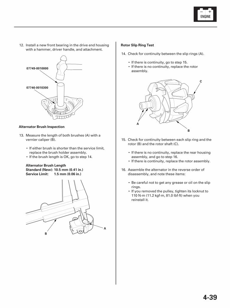
10
11
12
Alternator Brush Inspection
Alternator Brush Length
Standard (New): 10.5 mm (0.41 in.)
Service Limit: 1.5 mm (0.06 in.)
Rotor Slip Ring Test
4-39
07749-0010000
07746-0010300
B
A
A
B
C
12. Install a new front bearing in the drive end housingwith a hammer, driver handle, and attachment.
13. Measure the length of both brushes (A) with avernier caliper (B).
• If either brush is shorter than the service limit,replace the brush holder assembly.
• If the brush length is OK, go to step 14.
14. Check for continuity between the slip rings (A).
• If there is continuity, go to step 15.• If there is no continuity, replace the rotor
assembly.
15. Check for continuity between each slip ring and therotor (B) and the rotor shaft (C).
• If there is no continuity, replace the rear housingassembly, and go to step 16.
• If there is continuity, replace the rotor assembly.
16. Assemble the alternator in the reverse order ofdisassembly, and note these items:
• Be careful not to get any grease or oil on the sliprings.
• If you removed the pulley, tighten its locknut to110 N·m (11.2 kgf·m, 81.0 lbf·ft) when youreinstall it.
07/05/09 16:33:28 61SJC020_040_0040
*01
*02
SJC8A00A14500000000DAAT00
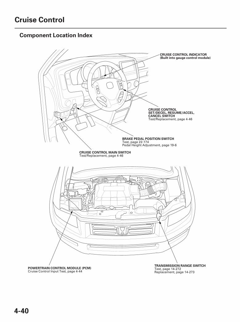
4-40
Cruise Control
Component Location Index
BRAKE PEDAL POSITION SWITCH
CRUISE CONTROL INDICATOR(Built into gauge control module)
CRUISE CONTROLSET/DECEL, RESUME/ACCEL,CANCEL SWITCH
CRUISE CONTROL MAIN SWITCH
TRANSMISSION RANGE SWITCHPOWERTRAIN CONTROL MODULE (PCM)
Test, page 22-174Pedal Height Adjustment, page 19-6
Test/Replacement, page 4-46
Test/Replacement, page 4-46
Test, page 14-272Replacement, page 14-273Cruise Control Input Test, page 4-44
07/05/09 16:33:45 61SJC020_040_0041
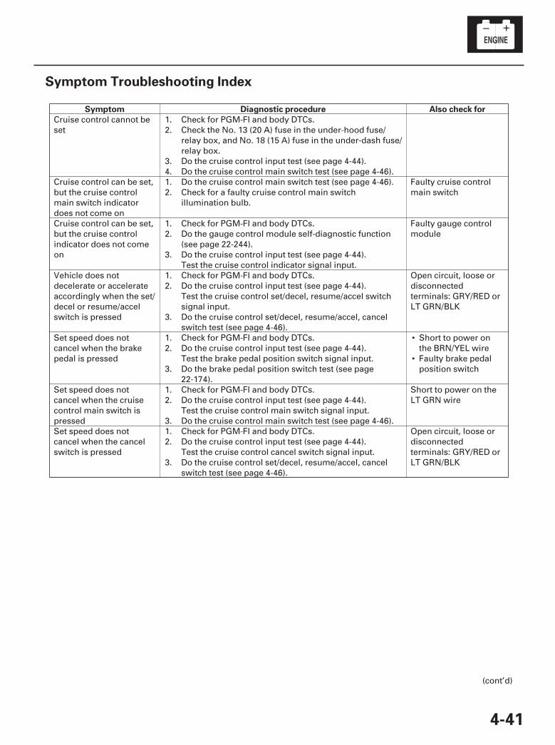
SJC8A00A14500000000HBAT01
Symptom Diagnostic procedure Also check for
4-41
Symptom Troubleshooting Index
•
•
Cruise control cannot beset
1.2.
3.4.
Check for PGM-FI and body DTCs.Check the No. 13 (20 A) fuse in the under-hood fuse/relay box, and No. 18 (15 A) fuse in the under-dash fuse/relay box.Do the cruise control input test (see page 4-44).Do the cruise control main switch test (see page 4-46).
Cruise control can be set,but the cruise controlmain switch indicatordoes not come on
1.2.
Do the cruise control main switch test (see page 4-46).Check for a faulty cruise control main switchillumination bulb.
Faulty cruise controlmain switch
Cruise control can be set,but the cruise controlindicator does not comeon
1.2.
3.
Check for PGM-FI and body DTCs.Do the gauge control module self-diagnostic function(see page 22-244).Do the cruise control input test (see page 4-44).Test the cruise control indicator signal input.
Faulty gauge controlmodule
Vehicle does notdecelerate or accelerateaccordingly when the set/decel or resume/accelswitch is pressed
1.2.
3.
Check for PGM-FI and body DTCs.Do the cruise control input test (see page 4-44).Test the cruise control set/decel, resume/accel switchsignal input.Do the cruise control set/decel, resume/accel, cancelswitch test (see page 4-46).
Open circuit, loose ordisconnectedterminals: GRY/RED orLT GRN/BLK
Set speed does notcancel when the brakepedal is pressed
1.2.
3.
Check for PGM-FI and body DTCs.Do the cruise control input test (see page 4-44).Test the brake pedal position switch signal input.Do the brake pedal position switch test (see page22-174).
Short to power onthe BRN/YEL wireFaulty brake pedalposition switch
Set speed does notcancel when the cruisecontrol main switch ispressed
1.2.
3.
Check for PGM-FI and body DTCs.Do the cruise control input test (see page 4-44).Test the cruise control main switch signal input.Do the cruise control main switch test (see page 4-46).
Short to power on theLT GRN wire
Set speed does notcancel when the cancelswitch is pressed
1.2.
3.
Check for PGM-FI and body DTCs.Do the cruise control input test (see page 4-44).Test the cruise control cancel switch signal input.Do the cruise control set/decel, resume/accel, cancelswitch test (see page 4-46).
Open circuit, loose ordisconnectedterminals: GRY/RED orLT GRN/BLK
(cont’d)
07/05/09 16:33:45 61SJC020_040_0042
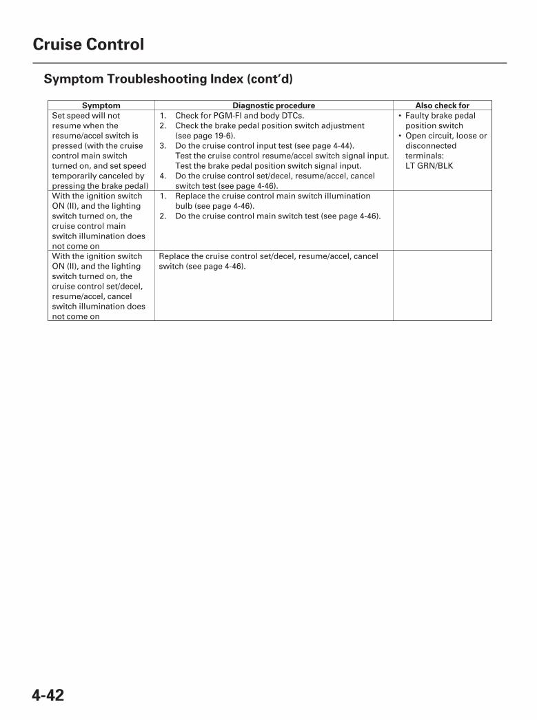
Symptom Diagnostic procedure Also check for
4-42
Cruise Control
Symptom Troubleshooting Index (cont’d)
•
•
Set speed will notresume when theresume/accel switch ispressed (with the cruisecontrol main switchturned on, and set speedtemporarily canceled bypressing the brake pedal)
1.2.
3.
4.
Check for PGM-FI and body DTCs.Check the brake pedal position switch adjustment(see page 19-6).Do the cruise control input test (see page 4-44).Test the cruise control resume/accel switch signal input.Test the brake pedal position switch signal input.Do the cruise control set/decel, resume/accel, cancelswitch test (see page 4-46).
Faulty brake pedalposition switchOpen circuit, loose ordisconnectedterminals:LT GRN/BLK
With the ignition switchON (II), and the lightingswitch turned on, thecruise control mainswitch illumination doesnot come on
1.
2.
Replace the cruise control main switch illuminationbulb (see page 4-46).Do the cruise control main switch test (see page 4-46).
With the ignition switchON (II), and the lightingswitch turned on, thecruise control set/decel,resume/accel, cancelswitch illumination doesnot come on
Replace the cruise control set/decel, resume/accel, cancelswitch (see page 4-46).
07/05/09 16:33:46 61SJC020_040_0043
*01
SJC8A00A14500000000EAAT00
-+
-
-
-
-
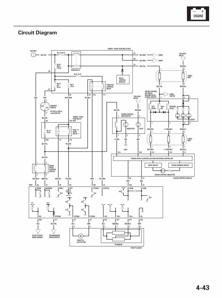
4-43
Circuit Diagram
431256
N29 X1 F19
D10A6
A1A36C4A20B3A6A7A8
SGTHL2THL1VCCETCSMETCSMATPFWDNC
A8 A1
A14 C20 C1A12A13
7 6 3
367
21
21
J4
H9
H1
BLU/RED HORN
F17E10X8E6
G1
D9
INDICATOR
(15 A)No.8
BLK/YEL
WHT
BLK/YEL
YEL/BLK
LIGHTS
RED/BLU
LT GRN/BLK
54
76
RED/BLK
RED/BLK
CABLEREEL
GRY/YEL
HORNBLU/RED
No.23(IG)(50 A)
(120 A)
LIGHT
CRUISE CONTROL INDICATOR
CRUISE DIMMING CIRCUITDRIVE CIRCUIT
POWER SUPPLY/CONTROLLER AREA NETWORK CONTROLLER
GRY/RED LT GRN/BLK
THROTTLE BODY
TP SENSOR
GRNRED/BLURED/BLKBLUGRNBLU
CANL
RED
5 V
IGP1
YEL/BLK
BLK/YEL
BLK/YEL
B19 B17C2
MRLY
PCM
12 V5 V
RED/YELBRN/YEL
WHT/GRN YEL/BLK
HORN RELAY
IG1BAT
21
WHT
YEL/GRN
C17B40 B34B12
ETCSRLY
GAUGE CONTROL MODULEBRN
2
1
4
3
G401
WHT/BLK
RED
RED/BLUGRY/RED
(15 A)No.18
GRY/YEL
(BAT)No.22
No.9 (15 A)
UNDER HOOD FUSE/RELAY BOX
BATTERYNo.13 (20 A)
3
31
BLK/YEL RED/BLK
REDBLKLT GRN
2 5 4
CANHIG1ETCSBKSWNCBKSW
C3
BLU BLU/YEL
REELCABLE
IG1 HOT in ON (II)and START (III)
CRUISE CONTROLMAIN SWITCH
THROTTLECONTROLRELAY
BRAKEPEDALPOSITIONSWITCH
THROTTLEACUTUATOR
OUTPUT SHAFTSPEED SENSOR
TRANSMISSIONRANGE SWITCH
SET/DECEL
CANCEL
RESUME/ACCEL
IGNITIONSWITCH
PGM FIMAINRELAY 1
HORNSWITCHTAILLIGHT
RELAY
TAILLIGHTRELAY
CRUISE CONTROLSET/DECEL,RESUME/ACCELCANCEL SWITCH
UNDER DASHFUSE/RELAYBOX
RELAYCONTROLMODULE
2
6
07/05/09 16:33:46 61SJC020_040_0044
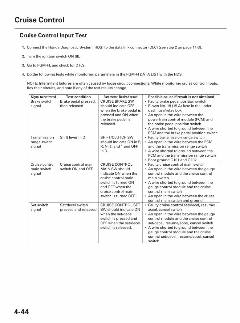
SJC8A00A14500000000FCAT00
Signal to be tested Parameter: Desired resultTest condition Possible cause if result is not obtained
4-44
Cruise Control
Cruise Control Input Test
1. Connect the Honda Diagnostic System (HDS) to the data link connector (DLC) (see step 2 on page 11-3).
2. Turn the ignition switch ON (II).
3. Go to PGM-FI, and check for DTCs.
4. Do the following tests while monitoring parameters in the PGM-FI DATA LIST with the HDS.
NOTE: Intermitent failures are often caused by loose circuit connections. While monitoring cruise control inputs,flex their circuits, and note if any of the test results change.
••
•
•
••
•
•••
•
•
•
•
•
Brake switchsignal
Brake pedal pressed,then released
CRUISE BRAKE SWshould indicate OFFwhen the brake pedal ispressed and ON whenthe brake pedal isreleased.
Faulty brake pedal position switchBlown No. 18 (15 A) fuse in the under-dash fuse/relay boxAn open in the wire between thepowertrain control module (PCM) andthe brake pedal position switchA wire shorted to ground between thePCM and the brake pedal position switch
Transmissionrange switchsignal
Shift lever in D SHIFT/CLUTCH SWshould indicate ON in P,R, N, 2, and 1 and OFFin D.
Faulty transmission range switchAn open in the wire between the PCMand the transmission range switchA wire shorted to ground between thePCM and the transmission range switchPoor ground G101 and G102
Cruise controlmain switchsignal
Cruise control mainswitch ON and OFF
CRUISE CONTROLMAIN SW shouldindicate ON when thecruise control mainswitch is turned ONand OFF when thecruise control mainswitch is turned OFF.
Faulty cruise control main switchAn open in the wire between the gaugecontrol module and the cruise controlmain switchA wire shorted to ground between thegauge control module and the cruisecontrol main switchAn open in the wire between the cruisecontrol main switch and ground
Set switchsignal
Set/decel switchpressed and released
CRUISE CONTROL SETSW should indicate ONwhen the set/decelswitch is pressed andOFF when the set/decelswitch is released.
Faulty cruise control set/decel, resume/accel, cancel switchAn open in the wire between the gaugecontrol module and the cruise controlset/decel, resume/accel, cancel switchA wire shorted to ground between thegauge control module and the cruisecontrol set/decel, resume/accel, cancelswitch
07/05/09 16:33:46 61SJC020_040_0045
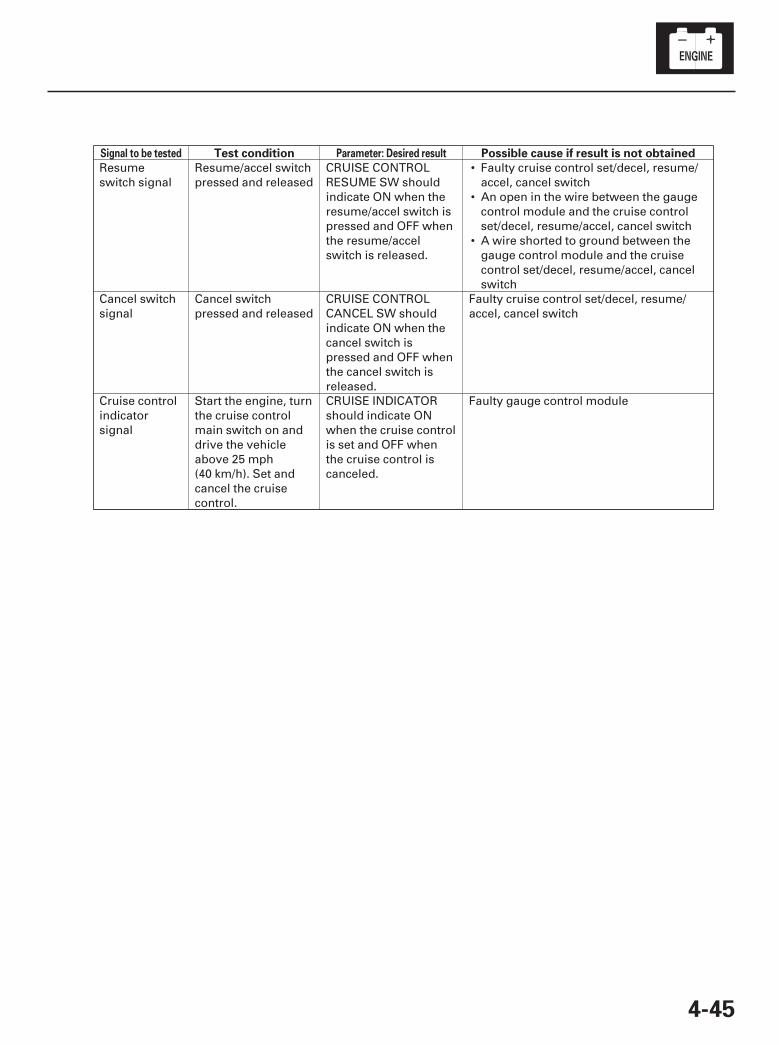
Signal to be tested Parameter: Desired resultTest condition Possible cause if result is not obtained
4-45
•
•
•
Resumeswitch signal
Resume/accel switchpressed and released
CRUISE CONTROLRESUME SW shouldindicate ON when theresume/accel switch ispressed and OFF whenthe resume/accelswitch is released.
Faulty cruise control set/decel, resume/accel, cancel switchAn open in the wire between the gaugecontrol module and the cruise controlset/decel, resume/accel, cancel switchA wire shorted to ground between thegauge control module and the cruisecontrol set/decel, resume/accel, cancelswitch
Cancel switchsignal
Cancel switchpressed and released
CRUISE CONTROLCANCEL SW shouldindicate ON when thecancel switch ispressed and OFF whenthe cancel switch isreleased.
Faulty cruise control set/decel, resume/accel, cancel switch
Cruise controlindicatorsignal
Start the engine, turnthe cruise controlmain switch on anddrive the vehicleabove 25 mph(40 km/h). Set andcancel the cruisecontrol.
CRUISE INDICATORshould indicate ONwhen the cruise controlis set and OFF whenthe cruise control iscanceled.
Faulty gauge control module
07/05/09 16:33:47 61SJC020_040_0046
01
01
SJC8A00A14500017611FHAT01
01
02
SJC8A00A14500017621FHAT02
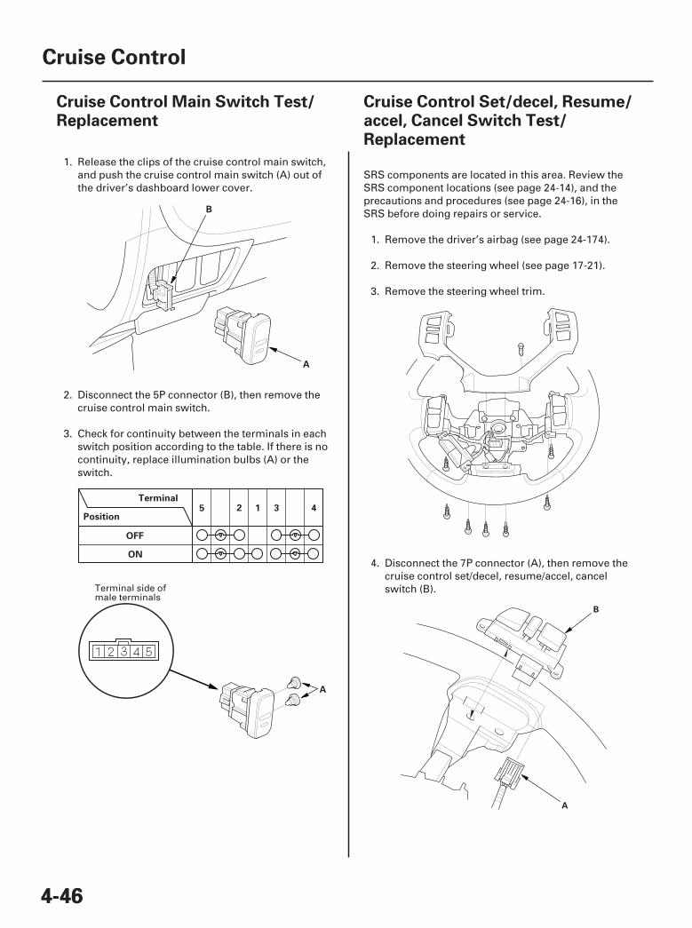
4-464-46
Cruise Control
Cruise Control Main Switch Test/Replacement
Cruise Control Set/decel, Resume/accel, Cancel Switch Test/Replacement
A
B
Terminal
Position
OFF
ON
12 3 45
A
B
A
1. Release the clips of the cruise control main switch,and push the cruise control main switch (A) out ofthe driver’s dashboard lower cover.
2. Disconnect the 5P connector (B), then remove thecruise control main switch.
3. Check for continuity between the terminals in eachswitch position according to the table. If there is nocontinuity, replace illumination bulbs (A) or theswitch.
SRS components are located in this area. Review theSRS component locations (see page 24-14), and theprecautions and procedures (see page 24-16), in theSRS before doing repairs or service.
1. Remove the driver’s airbag (see page 24-174).
2. Remove the steering wheel (see page 17-21).
3. Remove the steering wheel trim.
4. Disconnect the 7P connector (A), then remove thecruise control set/decel, resume/accel, cancelswitch (B).Terminal side of
male terminals
07/05/09 16:33:47 61SJC020_040_0047
03
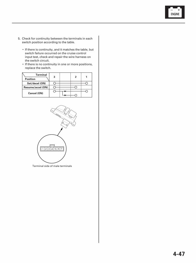
4-47
Terminal
Position
Set/decel (ON)
Resume/accel (ON)
Cancel (ON)
123
5. Check for continuity between the terminals in eachswitch position according to the table.
• If there is continuity, and it matches the table, butswitch failure occurred on the cruise controlinput test, check and repair the wire harness onthe switch circuit.
• If there is no continuity in one or more positions,replace the switch.
Terminal side of male terminals
07/05/09 16:33:47 61SJC020_040_0048