superposition of dc magnetic fields by cascading multiple...
TRANSCRIPT
Superposition of DC magnetic fields by cascading multiple magnets in magneticloopsFei Sun and Sailing He Citation: AIP Advances 5, 097208 (2015); doi: 10.1063/1.4931949 View online: http://dx.doi.org/10.1063/1.4931949 View Table of Contents: http://scitation.aip.org/content/aip/journal/adva/5/9?ver=pdfcov Published by the AIP Publishing Articles you may be interested in The “Shim-a-ring” magnet: Configurable static magnetic fields using a ring magnet with a concentricferromagnetic shim Appl. Phys. Lett. 102, 202409 (2013); 10.1063/1.4807778 Self-heating property under ac magnetic field and its evaluation by ac/dc hysteresis loops of NiFe 2 O 4nanoparticles J. Appl. Phys. 107, 09B322 (2010); 10.1063/1.3355936 Ring-chain structural transitions in a ferromagnetic particles system induced by a dc magnetic field J. Chem. Phys. 131, 034905 (2009); 10.1063/1.3179687 Magnetization dynamics driven by the combined action of ac magnetic field and dc spin-polarized current J. Appl. Phys. 99, 08G507 (2006); 10.1063/1.2165136 Chemomagnetic fields produced by solid combustion reactions Appl. Phys. Lett. 75, 1170 (1999); 10.1063/1.124632
Reuse of AIP Publishing content is subject to the terms at: https://publishing.aip.org/authors/rights-and-permissions. Download to IP: 61.164.42.140 On: Thu, 31 Mar
2016 05:20:18
AIP ADVANCES 5, 097208 (2015)
Superposition of DC magnetic fields by cascading multiplemagnets in magnetic loops
Fei Sun1 and Sailing He1,2,a1Centre for Optical and Electromagnetic Research, Zhejiang Provincial Key Laboratoryfor Sensing Technologies, JORCEP, East Building #5, Zijingang Campus,Zhejiang University, Hangzhou 310058, China2Department of Electromagnetic Engineering, School of Electrical Engineering, RoyalInstitute of Technology (KTH), S-100 44 Stockholm, Sweden
(Received 14 May 2015; accepted 16 September 2015; published online 24 September 2015)
A novel method that can effectively collect the DC magnetic field produced by multipleseparated magnets is proposed. With the proposed idea of a magnetic loop, the DCmagnetic field produced by these separated magnets can be effectively superimposedtogether. The separated magnets can be cascaded in series or in parallel. A novelnested magnetic loop is also proposed to achieve a higher DC magnetic field inthe common air region without increasing the DC magnetic field in each magneticloop. The magnetic loop can be made by a magnetic hose, which is designed bytransformation optics and can be realized by the combination of super-conductors andferromagnetic materials. C 2015 Author(s). All article content, except where other-wise noted, is licensed under a Creative Commons Attribution 3.0 Unported License.[http://dx.doi.org/10.1063/1.4931949]
I. INTRODUCTION
The DC magnetic field produced by a single magnet diverges very quickly in the free space andis limited by many factors (e.g. the rated current of the coil). One simple way to obtain a higher DCmagnetic field is to cascade many magnets together. However, there is no theoretical guide on howto efficiently put multiple magnets together to get an enhanced magnetic field.
Transformation optics (TO) is a novel method that can be utilized to control the DC magneticfield.1–4 In recent years, many novel devices for DC magnetic fields, such as DC magnetic cloaks,5,6
concentrators,7–12 lenses,13 magnetic hoses,14,15 and illusion devices for DC magnetic fields4 havebeen designed by TO. A magnetic hose (MH) is a special kind of medium that has been designedby TO and experimentally demonstrated by DC metamaterials.14 By extending a surface in thereference space to a region of space in the real space, we can obtain the MH filled in this region inthe real space. Such a special medium is also called the null-space medium,13,16 optical void,17 oroptic-null medium18 for the electromagnetic wave case. An MH performs like a special ‘waveguide’for DC magnetic fields, transferring the DC magnetic field to an arbitrarily long distance.14
Previous studies on the MH are focused on transferring the DC magnetic field to a long distance(without enhancement).14,15 Some other potential applications of the MH has also been proposed,e.g., increasing the magnetic coupling between nanomagnets,19 and controlling the quantum sys-tems.20 However there is no study on collecting DC magnetic field and achieving a higher DCmagnetic field in an air region through the magnetic loop composed by the MH. We first propose theidea of effectively collecting DC magnetic fields produced by separated magnets and obtain a higherenhanced DC magnetic field in an air region through magnetic loops in this paper.
In this paper we study how to effectively collect the DC magnetic field produced by manyseparated magnets together to form an enhanced DC magnetic field that cannot be achieved bya single magnet. More specifically, we use MHs to form a DC magnetic loop and place magnets
aCorresponding author: [email protected]
2158-3226/2015/5(9)/097208/7 5, 097208-1 ©Author(s) 2015
Reuse of AIP Publishing content is subject to the terms at: https://publishing.aip.org/authors/rights-and-permissions. Download to IP: 61.164.42.140 On: Thu, 31 Mar
2016 05:20:18
097208-2 F. Sun and S. He AIP Advances 5, 097208 (2015)
inside of this loop to cascade these magnets together. In this way the energy of these magnets canbe effectively utilized. Numerical simulations based on the finite element method (FEM) verifyour method (All simulations in this paper use the AC/DC module of COMSOL MULTIPHYSICSsoftware).
II. THE MAGNETIC HOSE
We first summarize the basic concept of an MH that has been designed by TO.14,15 An MH is ahighly anisotropic medium whose permeability is infinitely large along its main axis (the directionthat the DC magnetic flux is guided along) µ|| → ∞, and nearly zero in other directions orthogonalto its main axis µ⊥ → 0. For example, we can express the permeability of an MH whose main axis isin a Cartesian coordinate system as:
µ =
diag(∞,0,0), the main axis is along x directiondiag(0,∞,0), the main axis is along y directiondiag(0,0,∞), the main axis is along z direction
(1)
A previous study has shown that MHs can be approximately realized by the combination ofsuper-conductors (SCs) whose permeabilities are extremely small (due to its nearly perfect diamag-netism and ferromagnetic materials (FMs) whose permeabilities can be very large.14 The simplestsimplified version of MH is a structure with a superconductor shell and a ferromagnetic core, whichcan still perform approximately like an MH.
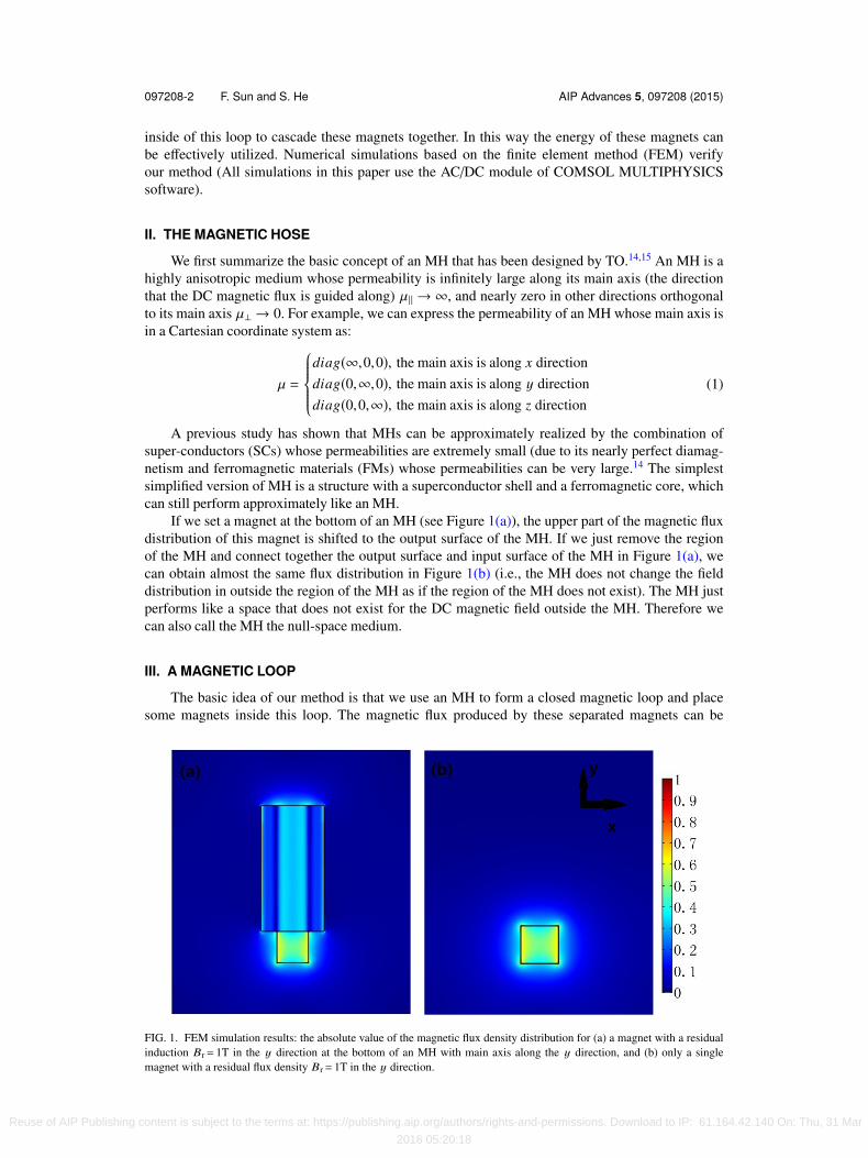
If we set a magnet at the bottom of an MH (see Figure 1(a)), the upper part of the magnetic fluxdistribution of this magnet is shifted to the output surface of the MH. If we just remove the regionof the MH and connect together the output surface and input surface of the MH in Figure 1(a), wecan obtain almost the same flux distribution in Figure 1(b) (i.e., the MH does not change the fielddistribution in outside the region of the MH as if the region of the MH does not exist). The MH justperforms like a space that does not exist for the DC magnetic field outside the MH. Therefore wecan also call the MH the null-space medium.
III. A MAGNETIC LOOP
The basic idea of our method is that we use an MH to form a closed magnetic loop and placesome magnets inside this loop. The magnetic flux produced by these separated magnets can be
FIG. 1. FEM simulation results: the absolute value of the magnetic flux density distribution for (a) a magnet with a residualinduction Br= 1T in the y direction at the bottom of an MH with main axis along the y direction, and (b) only a singlemagnet with a residual flux density Br= 1T in the y direction.
Reuse of AIP Publishing content is subject to the terms at: https://publishing.aip.org/authors/rights-and-permissions. Download to IP: 61.164.42.140 On: Thu, 31 Mar
2016 05:20:18
097208-3 F. Sun and S. He AIP Advances 5, 097208 (2015)
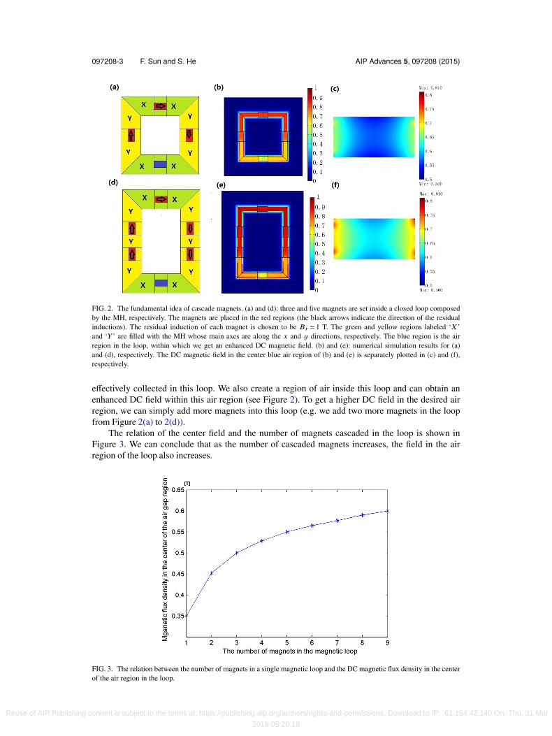
FIG. 2. The fundamental idea of cascade magnets. (a) and (d): three and five magnets are set inside a closed loop composedby the MH, respectively. The magnets are placed in the red regions (the black arrows indicate the direction of the residualinductions). The residual induction of each magnet is chosen to be Br = 1 T. The green and yellow regions labeled ‘X ’and ‘Y ’ are filled with the MH whose main axes are along the x and y directions, respectively. The blue region is the airregion in the loop, within which we get an enhanced DC magnetic field. (b) and (e): numerical simulation results for (a)and (d), respectively. The DC magnetic field in the center blue air region of (b) and (e) is separately plotted in (c) and (f),respectively.
effectively collected in this loop. We also create a region of air inside this loop and can obtain anenhanced DC field within this air region (see Figure 2). To get a higher DC field in the desired airregion, we can simply add more magnets into this loop (e.g. we add two more magnets in the loopfrom Figure 2(a) to 2(d)).
The relation of the center field and the number of magnets cascaded in the loop is shown inFigure 3. We can conclude that as the number of cascaded magnets increases, the field in the airregion of the loop also increases.
FIG. 3. The relation between the number of magnets in a single magnetic loop and the DC magnetic flux density in the centerof the air region in the loop.
Reuse of AIP Publishing content is subject to the terms at: https://publishing.aip.org/authors/rights-and-permissions. Download to IP: 61.164.42.140 On: Thu, 31 Mar
2016 05:20:18
097208-4 F. Sun and S. He AIP Advances 5, 097208 (2015)
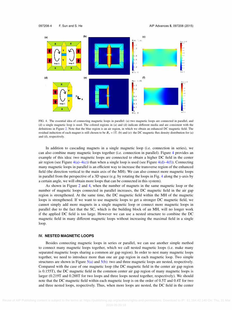
FIG. 4. The essential idea of connecting magnetic loops in parallel: (a) two magnetic loops are connected in parallel, and(d) a single magnetic loop is used. The colored regions in (a) and (d) indicate different media and are consistent with thedefinitions in Figure 2. Note that the blue region is an air region, in which we obtain an enhanced DC magnetic field. Theresidual induction of each magnet is still chosen to be Br = 1T. (b) and (e): the DC magnetic flux density distribution for (a)and (d), respectively.
In addition to cascading magnets in a single magnetic loop (i.e. connection in series), wecan also combine many magnetic loops together (i.e. connection in parallel). Figure 4 provides anexample of this idea: two magnetic loops are connected to obtain a higher DC field in the centerair region (see Figure 4(a)–4(c)) than when a single loop is used (see Figure 4(d)–4(f)). Connectingmany magnetic loops in parallel is an efficient way to increase the transverse region of the enhancedfield (the direction vertical to the main axis of the MH). We can also connect more magnetic loopsin parallel from the perspective of a 3D space (e.g. by rotating the loops in Fig. 4 along the y-axis bya certain angle, we will obtain more loops that can be connected in this system).
As shown in Figure 2 and 4, when the number of magnets in the same magnetic loop or thenumber of magnetic loops connected in parallel increases, the DC magnetic field in the air gapregion is strengthened. At the same time, the DC magnetic field within the MH of the magneticloops is strengthened. If we want to use magnetic loops to get a stronger DC magnetic field, wecannot simply add more magnets in a single magnetic loop or connect more magnetic loops inparallel due to the fact that the SC, which is the building block of an MH, will no longer workif the applied DC field is too large. However we can use a nested structure to combine the DCmagnetic field in many different magnetic loops without increasing the maximal field in a singleloop.
IV. NESTED MAGNETIC LOOPS
Besides connecting magnetic loops in series or parallel, we can use another simple methodto connect many magnetic loops together, which we call nested magnetic loops (i.e. make manyseparated magnetic loops sharing a common air gap region). In order to nest many magnetic loopstogether, we need to introduce more than one air gap region in each magnetic loop. Two simplestructures are shown in Figure 5(a) and 5(b): two and three magnetic loops are nested, respectively.Compared with the case of one magnetic loop (the DC magnetic field in the center air gap regionis 0.155T), the DC magnetic field in the common center air gap region of many magnetic loops islarger (0.219T and 0.288T for two loops and three loops nested together, respectively). We shouldnote that the DC magnetic field within each magnetic loop is on the order of 0.5T and 0.4T for twoand three nested loops, respectively. Thus, when more loops are nested, the DC field in the center
Reuse of AIP Publishing content is subject to the terms at: https://publishing.aip.org/authors/rights-and-permissions. Download to IP: 61.164.42.140 On: Thu, 31 Mar
2016 05:20:18
097208-5 F. Sun and S. He AIP Advances 5, 097208 (2015)
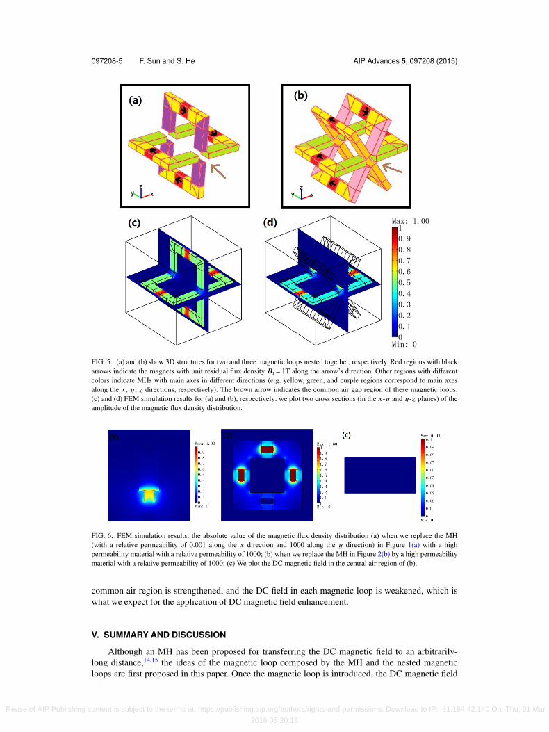
FIG. 5. (a) and (b) show 3D structures for two and three magnetic loops nested together, respectively. Red regions with blackarrows indicate the magnets with unit residual flux density Br= 1T along the arrow’s direction. Other regions with differentcolors indicate MHs with main axes in different directions (e.g. yellow, green, and purple regions correspond to main axesalong the x, y, z directions, respectively). The brown arrow indicates the common air gap region of these magnetic loops.(c) and (d) FEM simulation results for (a) and (b), respectively: we plot two cross sections (in the x-y and y-z planes) of theamplitude of the magnetic flux density distribution.
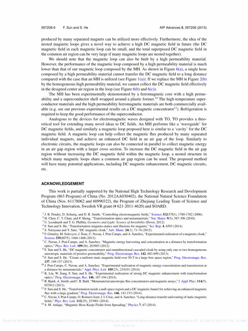
FIG. 6. FEM simulation results: the absolute value of the magnetic flux density distribution (a) when we replace the MH(with a relative permeability of 0.001 along the x direction and 1000 along the y direction) in Figure 1(a) with a highpermeability material with a relative permeability of 1000; (b) when we replace the MH in Figure 2(b) by a high permeabilitymaterial with a relative permeability of 1000; (c) We plot the DC magnetic field in the central air region of (b).
common air region is strengthened, and the DC field in each magnetic loop is weakened, which iswhat we expect for the application of DC magnetic field enhancement.
V. SUMMARY AND DISCUSSION
Although an MH has been proposed for transferring the DC magnetic field to an arbitrarily-long distance,14,15 the ideas of the magnetic loop composed by the MH and the nested magneticloops are first proposed in this paper. Once the magnetic loop is introduced, the DC magnetic field
Reuse of AIP Publishing content is subject to the terms at: https://publishing.aip.org/authors/rights-and-permissions. Download to IP: 61.164.42.140 On: Thu, 31 Mar
2016 05:20:18
097208-6 F. Sun and S. He AIP Advances 5, 097208 (2015)
produced by many separated magnets can be utilized more effectively. Furthermore, the idea of thenested magnetic loops gives a novel way to achieve a high DC magnetic field in future (the DCmagnetic field in each magnetic loop can be small, and the total superposed DC magnetic field inthe common air region can be very large if many magnetic loops are nested together).
We should note that the magnetic loop can also be built by a high permeability material.However, the performance of the magnetic loop composed by a high permeability material is muchlower than that of our magnetic loop composed by the MH. As shown in Figure 6(a), a single hosecomposed by a high permeability material cannot transfer the DC magnetic field to a long distancecompared with the case that an MH is utilized (see Figure 1(a)). If we replace the MH in Figure 2(b)by the homogeneous high permeability material, we cannot collect the DC magnetic field effectivelyin the designed center air region in the loop (see Figure 6(b) and 6(c)).
The MH has been experimentally demonstrated by a ferromagnetic core with a high perme-ability and a superconductor shell wrapped around a plastic former.14 The high-temperature super-conductor materials and the high permeability ferromagnetic materials are both commercially avail-able (e.g. see our previous experimental results on a DC magnetic concentrator11). Refrigeration isrequired to keep the good performance of the superconductor.
Analogous to the devices for electromagnetic waves designed with TO, TO provides a theo-retical tool for extending many novel ideas to DC fields. An MH performs like a ‘waveguide’ forDC magnetic fields, and similarly a magnetic loop proposed here is similar to a ‘cavity’ for the DCmagnetic field. A magnetic loop can help collect the magnetic flux produced by many separatedindividual magnets, and achieve an enhanced DC field in an air gap of the loop. Similarly toelectronic circuits, the magnetic loops can also be connected in parallel to collect magnetic energyin an air gap region with a larger cross section. To increase the DC magnetic field in the air gapregion without increasing the DC magnetic field within the magnetic loop, a nested structure inwhich many magnetic loops share a common air gap region can be used. The proposed methodwill have many potential applications, including DC magnetic enhancement, DC magnetic circuits,etc.
ACKNOWLEDGEMENT
This work is partially supported by the National High Technology Research and DevelopmentProgram (863 Program) of China (No. 2012AA030402), the National Natural Science Foundationof China (Nos. 61178062 and 60990322), the Program of Zhejiang Leading Team of Science andTechnology Innovation, Swedish VR grant (# 621-2011-4620) and SOARD.
1 J. B. Pendry, D. Schurig, and D. R. Smith, “Controlling electromagnetic fields,” Science 312(5781), 1780-1782 (2006).2 H. Chen, C. T. Chan, and P. Sheng, “Transformation optics and metamaterials,” Nat. Mater. 9(5), 387-396 (2010).3 U. Leonhardt and T. G. Philbin, Geometry and Light: Science of Invisibility (Dover, 2012).4 F. Sun and S. He, “Transformation magneto-statics and illusions for magnets,” Sci. Rep. 4, 6593 (2014).5 S. Narayana and Y. Sato, “DC magnetic cloak,” Adv. Mater. 24(1), 71-74 (2012).6 F. Gömöry, M. Solovyov, J. Šouc, C. Navau, J. Prat-Camps, and A. Sanchez, “Experimental realization of a magnetic cloak,”
Science 335(6075), 1466-1468 (2012).7 C. Navau, J. Prat-Camps, and A. Sanchez, “Magnetic energy harvesting and concentration at a distance by transformation
optics,” Phys. Rev. Lett. 109(26), 263903 (2012).8 F. Sun and S. He, “DC magnetic concentrator and omnidirectional cascaded cloak by using only one or two homogeneous
anisotropic materials of positive permeability,” Prog. Electromagn. Res. 142, 683-699 (2013).9 F. Sun and S. He, “Create a uniform static magnetic field over 50 T in a large free space region,” Prog. Electromagn. Res.
137, 149-157 (2013).10 J. Prat-Camps, C. Navau, and A. Sanchez, “Experimental realization of magnetic energy concentration and transmission at
a distance by metamaterials,” Appl. Phys. Lett. 105(23), 234101 (2014).11 K. Liu, W. Jiang, F. Sun, and S. He, “Experimental realization of strong DC magnetic enhancement with transformation
optics,” Prog. Electromagn. Res. 146, 187-194 (2014).12 R. Bjørk, A. Smith, and C. R. Bahl, “Metamaterial anisotropic flux concentrators and magnetic arrays,” J. Appl. Phys. 114(5),
053912 (2013).13 F. Sun and S. He, “Transformation inside a null-space region and a DC magnetic funnel for achieving an enhanced magnetic
flux with a large gradient,” Prog. Electromagn. Res. 146, 143-153 (2014).14 C. Navau, J. Prat-Camps, O. Romero-Isart, J. I. Cirac, and A. Sanchez, “Long-distance transfer and routing of static magnetic
fields,” Phys. Rev. Lett. 112(25), 253901 (2014).15 S. M. Anlage, “Magnetic Hose Keeps Fields from Spreading,” Physics 7, 67 (2014).
Reuse of AIP Publishing content is subject to the terms at: https://publishing.aip.org/authors/rights-and-permissions. Download to IP: 61.164.42.140 On: Thu, 31 Mar
2016 05:20:18

097208-7 F. Sun and S. He AIP Advances 5, 097208 (2015)
16 F. Sun and S. He, “Extending the scanning angle of a phased array antenna by using a null-space medium,” Sci. Rep. 4,6832 (2014).
17 M. M. Sadeghi, S. Li, L. Xu, B. Hou, and H. Chen, “Transformation optics with Fabry-P’erot resonances,” Sci. Rep. 5, 8680(2015).
18 Q. He, S. Xiao, X. Li, and L. Zhou, “Optic-null medium: realization and applications,” Opt. Express 21(23), 28948-28959(2013).
19 D. B. Carlton, N. C. Emley, E. Tuchfeld, and J. Bokor, “Simulation studies of nanomagnet-based logic architecture,” NanoLetters 8(12), 4173-4178 (2008).
20 J. Stajic, “The future of quantum information processing,” Science 339(6124), 1163-1163 (2013).
Reuse of AIP Publishing content is subject to the terms at: https://publishing.aip.org/authors/rights-and-permissions. Download to IP: 61.164.42.140 On: Thu, 31 Mar
2016 05:20:18