superhydrophobic and superoleophobic surfaces using zno nano-in-micro hierarchical structures
TRANSCRIPT
1
3
4
5
6
7 Q1
89
101112
1 4
15161718
192021222324
2 5
34
35
36
37
38
39
40
41
42
43
44
45
46
47
48
49
50
51
52
53
54
55
Q2
Microelectronic Engineering xxx (2013) xxx–xxx
MEE 9234 No. of Pages 7, Model 5G
30 October 2013
Contents lists available at ScienceDirect
Microelectronic Engineering
journal homepage: www.elsevier .com/locate /mee
Superhydrophobic and superoleophobic surfaces using ZnOnano-in-micro hierarchical structures q
0167-9317/$ - see front matter � 2013 The Authors. Published by Elsevier B.V. All rights reserved.http://dx.doi.org/10.1016/j.mee.2013.10.009
q This is an open-access article distributed under the terms of the CreativeCommons Attribution-NonCommercial-No Derivative Works License, which per-mits non-commercial use, distribution, and reproduction in any medium, providedthe original author and source are credited.⇑ Corresponding author at: Department of Nano Semiconductor Engineering,
Korea University, 5-1 Anam-dong, Sungbuk-Gu, Seoul 136-701, Republic of Korea.Tel.: +82 2 3290 3812; fax: +82 2 928 9584.
E-mail address: [email protected] (H. Lee).
Please cite this article in press as: H.-B. Jo et al., Microelectron. Eng. (2013), http://dx.doi.org/10.1016/j.mee.2013.10.009
Han-Byeol Jo a, Jehong Choi b, Kyeong-Jae Byeon b, Hak-Jong Choi b, Heon Lee a,b,⇑a Department of Nano Semiconductor Engineering, Korea University, 5-1 Anam-dong, Sungbuk-Gu, Seoul 136-701, Republic of Koreab Department of Materials Science and Engineering, Korea University, 5-1 Anam-dong, Sungbuk-Gu, Seoul 136-701, Republic of Korea
a r t i c l e i n f o a b s t r a c t
26272829303132
Article history:Received 22 August 2013Accepted 14 October 2013Available online xxxx
Keywords:Nano imprint lithographySuperhydrophobicSuperoleophobicZnO hierarchical structure
We have developed superhydrophobic and superoleophobic surfaces based on ZnO nano-in-microhierarchical structures on various large-area substrates. To fabricate the surfaces, ultraviolet nanoimprintlithography, a simple process enabling large-area patterning, was used in combination with hydrother-mal synthesis. The wetting properties of the surfaces were analyzed by contact and sliding angle mea-surements with various solvents and by experiments determining self-cleaning properties. Theseanalyses confirmed the superhydrophobicity and superoleophobicity of the fabricated surfaces.
� 2013 The Authors. Published by Elsevier B.V. All rights reserved.
33
56
57
58
59
60
61
62
63
64
65
66
67
68
69
70
71
72
73
74
75
76
77
1. Introduction
In nature, some organisms have surfaces with special functions[1–7]. The skin on the feet of a gecko with high adhesion capabilityallowing it to climb vertical surfaces [2,3], the legs of a water stri-der enabling it to stand and walk upon a water surface [4,5], andthe surface of lotus leaf capable of self-cleaning by the rollingmovement of droplets on the surface [6,7] are all representativesurfaces with special functions that occur in nature. Surfaces withsuch special functions are attributed to their structures composedof hierarchical micro and nanostructures. Nature-inspired researchstudies aimed at fabricating artificial surfaces with functionalitiesidentical to that of the surfaces present in natural organisms byreplicating their hierarchical structures have been pursued actively[8–14]. Among these, mimicking the hierarchical structure of lotusleaves that show superhydrophobicity has particularly gainedinterest because of the interesting properties of these surfaces suchas self-cleaning, anti-sticking, anti-corrosion, and drag-reduction[15–17]. Until recently, superhydrophobic hierarchical structuressuch as that in a lotus leaf have been fabricated and replicatedby using electroforming, lithography, sol–gel process, layer bylayer selfassembly, deposition and nanocasting [18–20]. Although
78
79
80
81
82
83
84
85
the fabrication of superhydrophobic hierarchical structures bythese methods has afforded successful results, limitations such asrestricted substrates to produce, process complexity, high costand difficulty of large area fabrication still remain. In this study,fabrication of superhydrophobic and superoleophobic surfaces onvarious large-area substrates using ZnO nano-in-micro hierarchicalstructures by the combination of ultraviolet nanoimprint lithogra-phy (UV NIL), a simple process which allows for large-areapattering, and hydrothermal synthesis was developed. Wettingproperties of the fabricated large-area ZnO nano-in-microhierarchical structures were analyzed by various methods suchas contact and sliding angle measurements and determination ofself-cleaning properties. The results of these analyses confirmedthe superhydrophobicity and superoleophobicity of the large-areaZnO nano-in-micro hierarchical structures. To fabricate thesesuperhydrophobic and superoleophobic ZnO nano-in-micro hierar-chical structures, first, a ZnO nano-particles dispersed resist wasdeveloped. Then, a circular cone shaped micro-pattern was pat-terned by UV NIL using the ZnO nano-particles dispersion resin.Subsequently, ZnO nanorods were grown on the surface of themicro-pattern by low temperature hydrothermal synthesis fromthe exposed ZnO nano-particless on the surface of the micro-pat-tern, which acted as the seeds. Therefore, the method used in thestudy circumvents the use of high-temperature processing, whichallows for the fabrication of the superhydrophobic and superoleo-phobic ZnO nano-in-micro hierarchical structures on transparentand flexible polymer films like PET as well as on substrates likeSi wafer and glass. Because of the use of UV NIL, these superhydro-phobic and superoleophobic structures can be fabricated uniformlyon large areas.

86
87
88
89
90
91
92
93
94
95
96
97
98
99
100
101
102
103
104
105
106
107
108
109
110
111
112
113
114
115
116
117
118
119
120
121
122
123
124
125
126
127
128
129
130
131
132
133
134
135
136
137
138
139
140
141
142
143
144
145
146
147
148
149
150
151
152
153
154
155
156
157
158
159
160
161
162
163
164
165
166
167
168
169
170
171
172
173
174
175
176
177
178
179
180
181
182
183
184
185
186
187
188
189
190
191
192
193
194
195
196
2 H.-B. Jo et al. / Microelectronic Engineering xxx (2013) xxx–xxx
MEE 9234 No. of Pages 7, Model 5G
30 October 2013
2. Experiment
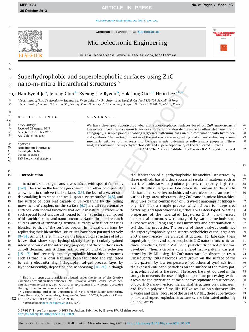
For the fabrication of the ZnO nano-in-micro hierarchicalstructure, first, a ZnO nano-particles dispersion resin was preparedfor use in the UV NIL. The resin was composed of ZnO nano-partic-less (diameter = 46.9), a monomer (Benzyl methacrylate), and asolvent (ethanol). Further details with regard to the preparationof the ZnO nano-particle dispersion resin are mentioned in our pre-vious paper [21]. Table 1 lists the components of the ZnO nano-particles resin. Scheme 1 shows the fabrication process of thesuperhydrophobic and superoleophobic ZnO nano-in-micro hierar-chical structures. As shown in Scheme 1, the micro-pattern arrayconsisting of the ZnO nano-particles and a poly(benzyl methacry-late)(PBzMA) was fabricated by UV NIL of the ZnO nano-particlesdispersion resin. In the UV NIL process, the ZnO nano-particles dis-persion resin was spin-coated on a pre-cleaned substrate at2000 rpm for 30 s. Subsequently, a PDMS mold was placed on theZnO nano-particles dispersion resin coated substrate. Then, thesubstrate covered with PDMS was subjected to a pressure of500 kPa along with the mold in order to fill the micro-scaled cavi-ties of PDMS mold with the ZnO nano-particle dispersion resin.Then UV irradiation was used to cure the ZnO nano-particles dis-persion resin whilst maintaining the applied pressure using a pres-sure vessel type imprint system. The PDMS mold was chosen as theUV imprint template because of its capability to absorb the solventwithout deformation and degradation of its UV transmittance. Fur-thermore, PDMS is advantageous for the fabrication of large-areapatterns because of its low surface energy which results in thesmooth detachment from the substrate after UV NIL. The PDMSmold with microcavities was replicated from a master stamp bysolution molding method and hence, its surface morphology wasopposite to that of the master stamp. The sapphire master stampfabricated by a series of processes including photolithographyand inductively coupled plasma reactive ion etching consisted ofmicro-patterns of 2.45 lm in diameter, 3 lm in pitch, and1.45 lm in height which were shaped like a circular cone.
After UV NIL, the PBzMA covering the surface of the micro-pattern was removed by O2 plasma reactive ion etching to exposethe ZnO nano-particless at the surface of the micro-pattern. ZnOnanorods were subsequently grown on the surface of these mi-cro-patterns by hydrothermal synthesis using the exposed ZnOnano-particless as seeds. The ZnO nanorods of various morpholo-gies could be grown by controlling the conditions of the hydrother-mal synthesis [22]. In this study, we grew hexagonal nanorodswith flat tops from the ZnO nano-particles seeds using a growthbasic aqueous solution containing 1 mM zinc nitride hexahydrate[Zn(NO3)2�6H2O] and 90 mM sodium hydroxide [NaOH] dissolvedin de-ionized water [23]. The ZnO nanorods were hydrothermallygrown on the surface of the micro pattern for a duration of 1 hby maintaining the solution temperature at 50 �C. After the ZnOnanorod synthesis, the surface of the ZnO nano-in-micro hierarchi-cal structure was fluorinated by dipping the structure into a solu-tion of heptadecafluoro-1,1,2,2-tetrahydrodecyl trichlorosilane(HDFS) (0.1 wt%) in n-hexane.
Fig. 1 shows the SEM images of four types of ZnO-polymercomposites on Si substrates with different surface morphologiesfabricated by UV NIL and hydrothermal synthesis using ZnO
197
198199
201201
202
203
204
205
Table 1Composition of the ZnO nano-particles dispersion resin.
Components Weight (%)
ZnO nano-particles 19BzMA (monomer) 47.5Ethanol (intrinsic solvent) 28.5Irgacure184 (photo-initiator) 5
Please cite this article in press as: H.-B. Jo et al., Microelectron. Eng. (2013), ht
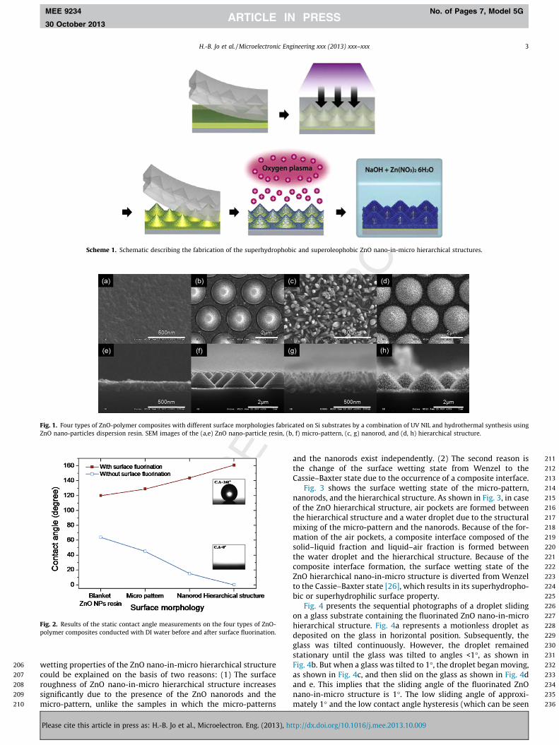
nano-particles dispersion resin. Fig. 1a and e are SEM images ofapproximately 120 nm thick blankets of the ZnO nano-particlesresin fabricated by spin-coating the resin on the substrate followedby UV irradiation. The ZnO nano-particles resin layer was uni-formly formed and the ZnO nano-particless constituting the blan-ket layer could be observed directly at the cross-section of theSEM image Fig. 1e. Fig. 1b and f are SEM images of the micro-pat-tern fabricated by carrying out UV NIL on the ZnO nano-particledispersion resin layer. As shown in the images, the shape of the mi-cro-pattern is nearly identical to the circular cone shape of the sap-phire master stamp. However, the size of the micro-pattern shrunkto 2.25 lm in diameter and 1.15 lm in height when compared tothat of the sapphire master stamp. The shrinkage is attributed tothe absorption of the solvent present in the ZnO nano-particles dis-persion resin by the PDMS mold during UV NIL. Fig. 1c and g arethe SEM micrographs of the ZnO nanorods grown by hydrothermalsynthesis on the blanket layer of the ZnO nano-particles dispersionresin shown in Fig. 1a and e. ZnO nano-particless were exposed atthe surface of the blanket layer of the nano-particles dispersionresin by O2 plasma reactive ion etching. Subsequently, the ZnOhexagonal nanorods with flat tops were grown to heights of about150 nm using the exposed ZnO nano-particless as seeds. In general,ZnO nanorods synthesized by hydrothermal process using thinfilms as seed materials grow vertically. However, in this case, theZnO nanorods grew in random directions, which can be attributedto growing the nanorods from randomly dispersed ZnO nano-particles seeds. Fig. 1d and h are the SEM images of the ZnOnano-in-micro hierarchical structure. The ZnO nano-in-micro hier-archical structures were fabricated by growing the ZnO nanorodfrom the micro-pattern shown in Fig. 1b and f. Similar to the nano-rods grown on the blanket of nano-particles resin, the ZnO nano-rods (120 nm in height) grew on the micro-pattern surfaces atrandom directions.
3. Result and discussion
Fig. 2 shows the results of the static contact angle measure-ments obtained on the four types of ZnO-polymer composites withDI water. These experiments were carried out for evaluating thesurface wetting properties of the composites. The static contact an-gles were measured before and after surface fluorination and theeach of the values furnished is the average of contact anglesobserved at five different points on every individual sample. Beforesurface fluorination, the static contact angle values showed adecreasing trend whilst spanning from the blanket layer sampleof ZnO nano-particles dispersion resin to the ZnO nano-in-microhierarchical structure. Especially, the static contact angle value ofthe ZnO nano-in-micro hierarchical structure was nearly zeroand DI water wetted the ZnO nano-in-micro hierarchical structureswell. In contrast, after surface fluorination, the static contact anglevalue showed an increasing tendency whilst spanning from theblanket ZnO nano-particles dispersion resin sample to the ZnOnano-in-micro hierarchical structure. In particular, the ZnO nano-in-micro hierarchical structure showed superhydrophobicity withstatic contact angles >160�. These results accurately correspondto the Wenzel model [24,25] according to which a hydrophobicsurface (h0 > 90�) becomes more hydrophobic with increase in Rf,while a hydrophilic surface (h0 < 90�) becomes more hydrophilicwith increase in Rf.
cos h ¼ Rf cos h0; where Rf ¼ASL
AFð1Þ
Furthermore, the ZnO nano-in-micro hierarchical structureconsisting of the ZnO nanorods and the micro-pattern showedsuperhydrophilic and superhydrophobic surface wetting proper-ties depending on the surface fluorination. The extreme surface
tp://dx.doi.org/10.1016/j.mee.2013.10.009
206
207
208
209
210
211
212
213
214
215
216
217
218
219
220
221
222
223
224
225
226
227
228
229
230
231
232
233
234
235
236
Scheme 1. Schematic describing the fabrication of the superhydrophobic and superoleophobic ZnO nano-in-micro hierarchical structures.
Fig. 1. Four types of ZnO-polymer composites with different surface morphologies fabricated on Si substrates by a combination of UV NIL and hydrothermal synthesis usingZnO nano-particles dispersion resin. SEM images of the (a,e) ZnO nano-particle resin, (b, f) micro-pattern, (c, g) nanorod, and (d, h) hierarchical structure.
Fig. 2. Results of the static contact angle measurements on the four types of ZnO-polymer composites conducted with DI water before and after surface fluorination.
H.-B. Jo et al. / Microelectronic Engineering xxx (2013) xxx–xxx 3
MEE 9234 No. of Pages 7, Model 5G
30 October 2013
wetting properties of the ZnO nano-in-micro hierarchical structurecould be explained on the basis of two reasons: (1) The surfaceroughness of ZnO nano-in-micro hierarchical structure increasessignificantly due to the presence of the ZnO nanorods and themicro-pattern, unlike the samples in which the micro-patterns
Please cite this article in press as: H.-B. Jo et al., Microelectron. Eng. (2013), ht
and the nanorods exist independently. (2) The second reason isthe change of the surface wetting state from Wenzel to theCassie–Baxter state due to the occurrence of a composite interface.
Fig. 3 shows the surface wetting state of the micro-pattern,nanorods, and the hierarchical structure. As shown in Fig. 3, in caseof the ZnO hierarchical structure, air pockets are formed betweenthe hierarchical structure and a water droplet due to the structuralmixing of the micro-pattern and the nanorods. Because of the for-mation of the air pockets, a composite interface composed of thesolid–liquid fraction and liquid–air fraction is formed betweenthe water droplet and the hierarchical structure. Because of thecomposite interface formation, the surface wetting state of theZnO hierarchical nano-in-micro structure is diverted from Wenzelto the Cassie–Baxter state [26], which results in its superhydropho-bic or superhydrophilic surface property.
Fig. 4 presents the sequential photographs of a droplet slidingon a glass substrate containing the fluorinated ZnO nano-in-microhierarchical structure. Fig. 4a represents a motionless droplet asdeposited on the glass in horizontal position. Subsequently, theglass was tilted continuously. However, the droplet remainedstationary until the glass was tilted to angles <1�, as shown inFig. 4b. But when a glass was tilted to 1�, the droplet began moving,as shown in Fig. 4c, and then slid on the glass as shown in Fig. 4dand e. This implies that the sliding angle of the fluorinated ZnOnano-in-micro structure is 1�. The low sliding angle of approxi-mately 1� and the low contact angle hysteresis (which can be seen
tp://dx.doi.org/10.1016/j.mee.2013.10.009

237
238
239
240
241
242
243
244
245
246
247
248
249
250
251
252
253
254
255
256
257
258
259
260
261
262
263
264
265
266
267
268
269
270
271
272
273
274
275
276
277
278
279
280
281
282
283
284
285
286
287
288
289
290
291
292
293
294
295
296
297
298
299
300
301
302
303
304
305
306
307
308
Fig. 3. Surface wetting of (a) the micro-pattern, (b) nanorods, and (c) the hierarchical structure.
Fig. 4. Sequential photographs of a droplet sliding on a glass substrate containing the fluorinated ZnO nano-in-micro hierarchical structure.
Fig. 5. Sequential photographs of a droplet (10 ll) contacted with and detached from the fluorinated ZnO nano-in-micro hierarchical structure on Si substrate.
4 H.-B. Jo et al. / Microelectronic Engineering xxx (2013) xxx–xxx
MEE 9234 No. of Pages 7, Model 5G
30 October 2013
in Fig. 9) are demonstrate clearly that the wetting state of the ZnOnano-in-micro hierarchical structure is not Wenzel butCassie–Baxter.
The wettability of the superhydrophobic ZnO nano-in-microhierarchical structure was further evaluated by a droplet contactexperiment. Fig. 5 shows the sequential photographs of a 10 lldroplet contacted with and detached from the fluorinated ZnOnano-in-micro hierarchical structure present on the Si substrate.Initially, the droplet appeared a little droopy shape because ofself-gravity Fig. 5a. Thereafter, the droplet moved down continu-ously from the hanging end of the syringe, to make exact, tight,and extreme contact with the substrate. The shape of the dropletremained nearly un-deformed until exact Fig. 5b and tight Fig. 5ccontact was achieved. However, after making extreme contactFig. 5d, the droplet deformed significantly to the extent that eventhe center of the droplet was away from the syringe. Subsequently,the droplet detached from the substrate after tight Fig. 5e andexact contact Fig. 5f sequentially while lifted up gradually fromthe substrate. As shown in Fig. 5f, after the droplet detached fromthe substrate, hardly any water residue remained on the Si sub-strate containing the fluorinated ZnO nano-in-micro hierarchicalstructure. This means that the surface energy of the Si substratecontaining the fluorinated ZnO nano-in-micro hierarchical struc-ture was extremely low, and the adhesive force between the drop-let and the Si substrate containing the fluorinated ZnO nano-in-micro hierarchical structure was absent.
In Fig. 6, the sequential photographs showing the self-cleaningeffect of the glass substrate containing the fluorinated ZnO nano-in-micro hierarchical structure are presented. To verify the self-cleaning effect of the fluorinated ZnO nano-in-micro hierarchicalstructure, a glass substrate (3.3 � 3.3 cm2) containing the fluori-nated ZnO nano-in-micro hierarchical structure was covered withreal dust and tiled to 1� to enable the sliding of the droplet, asshown in Fig. 4. Then, a droplet was placed onto the dust coveredglass using a syringe. The droplets placed rolled off the glass sur-face containing the fluorinated ZnO nano-in-micro hierarchical
Please cite this article in press as: H.-B. Jo et al., Microelectron. Eng. (2013), ht
structure, such that the dust covering the glass was cleaned bythe rolling droplets without leaving trace.
This result demonstrates that the fluorinated ZnO nano-in-micro hierarchical structures show remarkable self-cleaning effect.This self-cleaning effect of the fluorinated ZnO nano-in-micro hier-archical structure, which is often termed as the lotus effect,resulted from the extremely low surface energy attributed to thehigh structural roughness and the presence of air pockets in thehierarchical structure. Therefore, a droplet was prevented fromflowing, which enables it to roll off the surface while removingthe dust.
It is to be noted that the fabrication of the superhydrophobicZnO nano-in-micro hierarchical structure entails only the use ofUV NIL and low-temperature hydrothermal synthesis. The processdoes not involve any high-temperature heat treatments. Because ofthis advantage, it is possible to render any substrate by this fabri-cation process.
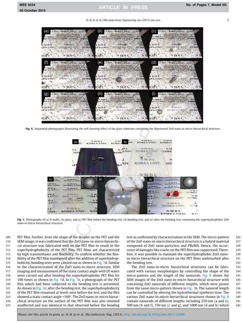
Fig. 7 is shows the photographs of various substrates (a) Siwafer, (b) glass, (c, d, and e) PET films, with the superhydrophobicZnO nano-in-micro hierarchical structure. The superhydrophobicSi wafer with uniformly formed ZnO nano-in-micro hierarchicalstructure on the 3.3 � 3.3 cm2 substrate is shown in Fig. 7a. A drop-let of water on the Si wafer maintained a nearly circular shape witha contact angle >160� because of its surface superhydrophobicity.Fig. 7b shows the superhydrophobic glass with ZnO nano-in-microhierarchical structure on its surface. Similar to the Si wafer, a waterdroplet on the superhydrophobic glass was nearly circular. The sizeof the glass was identical to that of the Si wafer. Further, the glasswas considerably transparent and the character underneath theglass could be read clearly. The superhydrophobic ZnO nano-in-micro hierarchical structure was also fabricated on flexible PETsubstrates in addition to the rigid Si wafer and glass.
Fig. 7c shows the photograph of the superhydrophobic PET filmwith the ZnO nano-in-micro hierarchical structure on its surface.Similar to the glass substrate, the PET film was transparent enoughto be able to distinctly observe and read characters underneath the
tp://dx.doi.org/10.1016/j.mee.2013.10.009
309
310
311
312
313
314
315
316
317
318
319
320
321
322
323
324
325
326
327
328
329
330
331
332
333
334
335
336
337
338
339
340
341
342
Fig. 6. Sequential photographs illustrating the self-cleaning effect of the glass substrate containing the fluorinated ZnO nano-in-micro hierarchical structure.
Fig. 7. Photographs of (a) Si wafer, (b) glass, and (c) PET film before the bending test, (d) bending test, and (e) after the bending test, containing the superhydrophobic ZnOnano-in-micro hierarchical structure.
H.-B. Jo et al. / Microelectronic Engineering xxx (2013) xxx–xxx 5
MEE 9234 No. of Pages 7, Model 5G
30 October 2013
PET film. Further, from the shape of the droplet on the PET and theSEM image, it was confirmed that the ZnO nano-in-micro hierarchi-cal structure was fabricated well on the PET film to result in thesuperhydrophobicity of the PET film. PET films are characterizedby high transmittance and flexibility. To confirm whether the flex-ibility of the PET film maintained after the addition of superhydrop-hobicity, bending tests were carried out as shown in Fig. 7d. Similarto the characterization of the ZnO nano-in-micro structure, SEMimaging and measurement of the static contact angle with DI waterwere carried out after bending the superhydrophobic PET film for100 times as shown in Fig. 7d. In Fig. 7e, a photograph of the PETfilm which had been subjected to the bending test is presented.As shown in Fig. 7e, after the bending test, the superhydrophobicityof the PET film remained at levels seen before the test, and the filmshowed a static contact angle >160�. The ZnO nano-in-micro hierar-chical structure on the surface of the PET film was also retainedunaffected and was identical to that observed before the bending
Please cite this article in press as: H.-B. Jo et al., Microelectron. Eng. (2013), ht
test as confirmed by characterization in the SEM. The micro-patternof the ZnO nano-in-micro hierarchical structure is a hybrid materialcomposed of ZnO nano-particless and PBzMA. Hence, the occur-rence of damages like cracks on the PET film was suppressed. There-fore, it was possible to maintain the superhydrophobic ZnO nano-in-micro hierarchical structure on the PET films undisturbed afterthe bending test.
The ZnO nano-in-micro hierarchical structures can be fabri-cated with various morphologies by controlling the shape of themicro-pattern and the length of the nanorods. Fig. 8 shows theSEM images of the ZnO nano-in-micro hierarchical structure withcontaining ZnO nanorods of different lengths, which were grownfrom the same micro-pattern shown in Fig. 1b. The nanorod lengthcan be controlled by altering the hydrothermal synthesis time. Thevarious ZnO nano-in-micro hierarchical structures shown in Fig. 8contain nanorods of different lengths including 250 nm (a and e),500 nm (b and f), 750 nm (c and g), and 1000 nm (d and h) which
tp://dx.doi.org/10.1016/j.mee.2013.10.009

343
344
345
346
347
348
349
350
351
352
353
354
355
356
357
358
359
360
361
362
363
364
365
366
367
368
369370372372
373
374
375
376
377
378
379
380
381
382
383
384
385
386
387
388
389
390
391
392
393
394
395
396
397
398
399
400
401
402
403
404
405
406
407
408
409
410
411
412
413
414
Fig. 8. SEM images of the ZnO nano-in-micro hierarchical structures with different ZnO nanorod lengths grown from the same micro-pattern. (a and e), (b and f), (c and g),and (d and h) represent samples with nanorod lengths of 250, 500, 750, and 1000 nm, respectively.
Fig. 9. Static contact angle of DI water, diiodomethane, and hexadecane on thefluorinated ZnO nano-in-micro hierarchical structure along with the results of thecontact angle hysteresis experiments.
6 H.-B. Jo et al. / Microelectronic Engineering xxx (2013) xxx–xxx
MEE 9234 No. of Pages 7, Model 5G
30 October 2013
were synthesized by carrying out the hydrothermal process for 1,2, 3, and 4 h, respectively. Since the ZnO nanorod was grown ver-tically to the micro-pattern surface, the morphologies of the ZnOnano-in-micro hierarchical structures were varied from a gravelike shape(Fig. 8a,e) to a sea urchin like shape(Fig. 8d,h) dependingon the increased length of the ZnO nanorods. Thus, the morphologyof the ZnO nano-in-micro structure was different depending on thelength of the nanorods even if they were fabricated from the samemicro-pattern. Accordingly, the surface wetting properties of theZnO nano-in-micro structure can be expected to vary with thelength of the ZnO nanorods. Therefore, in addition to measuringthe static angle with DI water and the contact angle hysteresis,the static contact angle of liquids exhibiting lower surface tensionthan DI water (72.8 mN/m) like diiodomethane (50.8 mN/m) andhexadecane (27.05 mN/m) were measured.
According to the contact angle measurements shown in Fig. 9,the static contact angle of DI water on the ZnO nano-in-micro hier-archical structures were all >160� with values ranging to 160�,162�, 166�, and 164� when the ZnO nanorod lengths were 250,500, 750, and 1000 nm, respectively. Also, the values of the contactangle hysteresis for these samples were very low at 1.8�, 1�, 0.6�,and 0.6�, respectively. Hence, from these results it can be con-firmed that the surfaces of the 4 types of ZnO nano-in-micro hier-archical structures consisting of nanorods of different lengths wereall superhydrophobic and exhibited Cassie–Baxter state. Accord-ingly, the contact angle followed the Cassie–Baxter equation givenin Eq. (2).
cos h ¼ �1þ fSLð1þ cos h0Þ ð2Þ
where fSL is the fraction of the solid–liquid surface area, h is theapparent contact angle on the rough surface, and h0 is the equilib-rium contact angle on a smooth surface of the same material. fSL
of the 4 types of ZnO nano-in-micro hierarchical structures werevery low and were in the range 0.059–0.12. Hence, most of the con-tact area of the DI water on the ZnO nano-in-micro hierarchicalstructure was composed of liquid–air fraction. Further, the staticcontact angle of diiodomethane on the four types of ZnO nano-in-micro hierarchical structures were all >155� with the individualvalues ranging to 158.5�, 158.3�, 159�, and 156.7�, when the ZnOnanorod lengths were 250, 500, 750, and 1000 nm, respectively.Difference in the contact angle among the 4 types of ZnO nano-in-micro hierarchical structures was only 2.3�. However, the staticcontact angles of hexadecane showed relatively larger differencesranging from 6.4� to 10.2� and the individual contact angles of hexa-decane were 125�, 131.4�, 123.6�, and 121.2� on samples consistingof 250, 500, 750, and 1000 nm long ZnO nanorods, respectively. Thevariation in the static contact angle of hexadecane with the nanorod
Please cite this article in press as: H.-B. Jo et al., Microelectron. Eng. (2013), ht
length can be attributed to the effect of the hierarchical structure onthe surface wetting property, which is maximized when the lengthof the nanorod is at a specific ratio to the size of the micro-patternand is decreased the nanorods exceed a critical length. Further, inthe ZnO nano-in-micro hierarchical structure, the size and shapeof the air pockets formed between the liquid and the hierarchicalstructure differ with the nanorod length and can be optimized bya certain ratio of the ZnO nanorod length to the micro-patterndimensions to achieve superhydrophobicity and superoleophobic-ity. These results indicate that the superhydrophobic and super-oleophobic ZnO nano-in-micro hierarchical structure which repeloil and DI water could be fabricated on large areas, on various sub-strates including rigid Si wafer, glass, and flexible PET film by thecombination of UV NIL and hydrothermal synthesis.
4. Conclusion
In this study, superhydrophobic and superoleophobic ZnOnano-in-micro hierarchical structures were fabricated on largeareas and various substrates and the surface wetting propertiesof these surfaces were evaluated. For the fabrication, first, a resinof dispersed ZnO nano-particless was produced on which UV NILand hydrothermal synthesis were subsequently applied. The ZnOnano-in-micro hierarchical structure showed a high degree ofsuperhydrophobicity and the water droplet on these surfacesexhibited a static contact angle >160�. Further, the contact angle
tp://dx.doi.org/10.1016/j.mee.2013.10.009
415
416
417
418
419
420
421
422
423
424
425
426
427
428
429
430431432433
434435436437438439440441442443444445446447448449450451452453454455456457458459
H.-B. Jo et al. / Microelectronic Engineering xxx (2013) xxx–xxx 7
MEE 9234 No. of Pages 7, Model 5G
30 October 2013
hysteresis was <2� and the sliding angle was <1�. This behavior wasattributed to the structural formation of air pockets due to the mix-ture of micro-patterns and nanorods. Accordingly, the ZnO nano-in-micro hierarchical structure showed practical self-cleaning ef-fects and nonwetting properties. The surface morphology of thehierarchical structure varied depending on the length of the ZnOnanorod and high degree of superoleophobicity. The structuresoil as well as DI water when the length of ZnO nanorod was at aspecific ratio to the micro-pattern dimensions. Therefore, we havedemonstrated the superhydrophobicity and superoleophobicity ofZnO nano-in-micro hierarchical structures, which could be fabri-cated on large areas, on various substrates including rigid Si wafer,glass, and flexible PET film by a combination of UV NIL and hydro-thermal synthesis.
References
[1] B. Bhushan, Y.C. Jung, Prog. Mater Sci. 56 (2011) 1–108.[2] H. Gao, X. Wang, H. Yao, S. Gorb, E. Arzt, Mech. Mater. 37 (2005) 275–285.[3] S. Sethi, L. Ge, L. Ci, P.M. Ajayan, A. Dhinojwala, Nano Lett. 8 (2008) 822–825.[4] X.Q. Feng, X. Gao, Z. Wu, L. Jiang, Q.S. Zheng, Langmuir 23 (2007) 4892–4896.
460
Please cite this article in press as: H.-B. Jo et al., Microelectron. Eng. (2013), ht
[5] X. Gao, L. Jiang, Nature 432 (2004) 36.[6] B. Bhushan, Y.C. Jung, Philos. Trans. R. Soc. A 367 (2009) 1631–1672.[7] K. Koch, B. Bhushan, Y.C. Jung, W. Barthlott, Soft Matter 5 (2009) 1386–1393.[8] Z. Guo, X. Chen, J. Li, J.H. Liu, X.J. Huang, Langmuir 27 (2011) 6193–6200.[9] X. Yao, Q. Chen, L. Xu, Q. Li, Y. Song, X. Gao, Adv. Funct. Mater. 20 (2010) 656–
662.[10] F. Zhang, H.Y. Low, Langmuir 23 (2007) 7793–7798.[11] X. Yao, L. Xu, L. Jiang, Adv. Funct. Mater. 20 (2010) 3343–3349.[12] C.T. Hsieh, F.L. Wu, W.Y. Chen, Mater. Chem. Phys. 121 (2010) 14–21.[13] T. Fujii, Y. Aoki, H. Habazaki, Langmuir 27 (2011) 11752–11756.[14] L. Zhai, M.C. Berg, F.C. Cebeci, Y. Kim, J.M. Milwid, M.F. Rubner, R.E. Cohen,
Nano Lett. 6 (2006) 1213–1217.[15] W. Zhao, L. Wang, Q. Xue, J. Phys. Chem. C 114 (2010) 11509–11514.[16] L. Jiang, Y. Zhao, J. Zhai, Angew. Chem. 116 (2004) 4438–4441.[17] L. Zhai, F. Cü, Nano Lett. 4 (2004) 1349–1353.[18] M. Ma, R.M. Hill, Curr. Opin. Colloid 11 (2006) 193–202.[19] M. Sun, C. Luo, L. Xu, Langmuir 21 (2005) 8978–8981.[20] S.M. Lee, T.H. Kwon, Nanotechnology 17 (2006) 3189–3196.[21] H.B. Jo, K.J. Byeon, M.H. Kwon, K.W. Choi, H. Lee, J. Mater. Chem. 22 (2012)
20742–20746.[22] K.S. Kim, H. Jeong, M.S. Jeong, G.Y. Jung, Adv. Funct. Mater. 20 (2010) 3055–
3063.[23] R.B. Peterson, C.L. Fields, B.A. Gregg, Langmuir 20 (2004) 5114–5118.[24] R.N. Wenzel, Ind. Eng. Chem. 28 (1936) 988–994.[25] R.N. Wenzel, J. Phys. Chem. 53 (1949) 1466–1467.[26] A.B.D. Cassie, Discuss. Faraday Soc. 3 (1948) 11.
tp://dx.doi.org/10.1016/j.mee.2013.10.009