super maxi relief valve catalogue - fort vale
TRANSCRIPT
SUPER MAXIRELIEF VALVE CATALOGUE//
The Fort ValeRange of Super Maxi & Hyper Maxi Relief Valves
© Fort Vale Engineering Ltd. 2017
®
REVISION_16.01.17
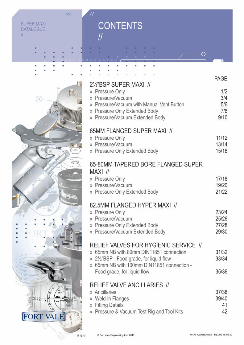
CONTENTS//
SUPER MAXICATALOGUE//
© Fort Vale Engineering Ltd. 2017 MAXI_CONTENTS1 REV05-16.01.17
®
2½”BSP SUPER MAXI //» Pressure Only » Pressure/Vacuum » Pressure/Vacuum with Manual Vent Button » Pressure Only Extended Body » Pressure/Vacuum Extended Body
65MM FLANGED SUPER MAXI //» Pressure Only » Pressure/Vacuum » Pressure Only Extended Body
65-80MM TAPERED BORE FLANGED SUPER MAXI //» Pressure Only » Pressure/Vacuum » Pressure Only Extended Body
82.5MM FLANGED HYPER MAXI //» Pressure Only » Pressure/Vacuum » Pressure Only Extended Body » Pressure/Vacuum Extended Body
RELIEF VALVES FOR HYGIENIC SERVICE //» 65mm NB with 80mm DIN11851 connection » 2½”BSP - Food grade, for liquid flow » 65mm NB with 100mm DIN11851 connection - Food grade, for liquid flow
RELIEF VALVE ANCILLARIES //» Ancillaries » Weld-in Flanges » Fitting Details » Pressure & Vacuum Test Rig and Tool Kits
PAGE
1/2 3/45/67/8
9/10
11/1213/1415/16
17/1819/2021/22
23/2425/2627/2829/30
31/3233/34
35/36
37/3839/40
4142
Range
Associated Parts
REL058 REV04-17.12.15
Fitting Details
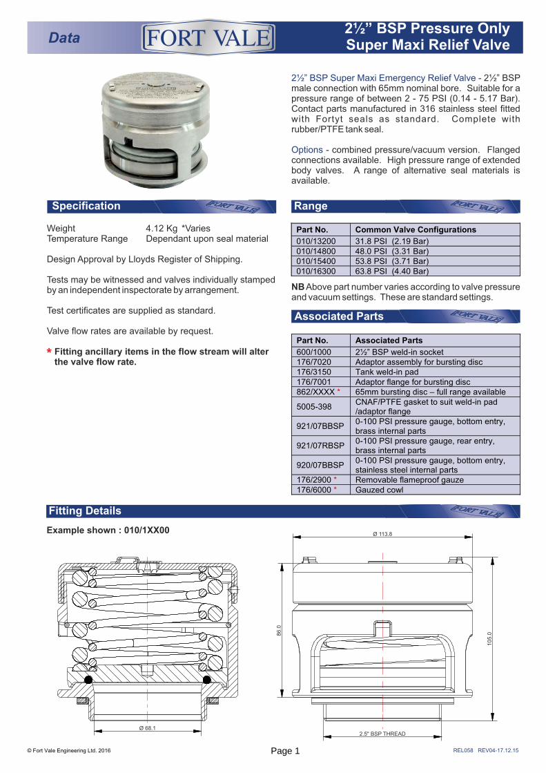
2½” BSP Super Maxi Emergency Relief Valve - 2½” BSP male connection with 65mm nominal bore. Suitable for a pressure range of between 2 - 75 PSI (0.14 - 5.17 Bar). Contact parts manufactured in 316 stainless steel fitted with Fortyt seals as standard. Complete with rubber/PTFE tank seal.
Options - combined pressure/vacuum version. Flanged connections available. High pressure range of extended body valves. A range of alternative seal materials is available.
Specification
© Fort Vale Engineering Ltd. 2016
Data® 2½” BSP Pressure Only
Super Maxi Relief Valve
Example shown : 010/1XX00
NB Above part number varies according to valve pressure and vacuum settings. These are standard settings.
Part No. Common Valve Configurations
010/13200 31.8 PSI (2.19 Bar) 010/14800 48.0 PSI (3.31 Bar) 010/15400 53.8 PSI (3.71 Bar) 010/16300 63.8 PSI (4.40 Bar)
Part No. Associated Parts
600/1000 2½” BSP weld-in socket 176/7020 Adaptor assembly for bursting disc 176/3150 Tank weld-in pad 176/7001 Adaptor flange for bursting disc 862/XXXX * 65mm bursting disc – full range available
5005-398 CNAF/PTFE gasket to suit weld-in pad /adaptor flange
921/07BBSP 0-100 PSI pressure gauge, bottom entry, brass internal parts
921/07RBSP 0-100 PSI pressure gauge, rear entry, brass internal parts
920/07BBSP 0-100 PSI pressure gauge, bottom entry, stainless steel internal parts
176/2900 * Removable flameproof gauze 176/6000 * Gauzed cowl
Weight 4.12 Kg *VariesTemperature Range Dependant upon seal material
Design Approval by Lloyds Register of Shipping.
Tests may be witnessed and valves individually stamped by an independent inspectorate by arrangement.
Test certificates are supplied as standard.
Valve flow rates are available by request.
Fitting ancillary items in the flow stream will alter the valve flow rate.*
Ø 68.12.5" BSP THREAD
Ø 113.8
105.08
6.0
Page 1
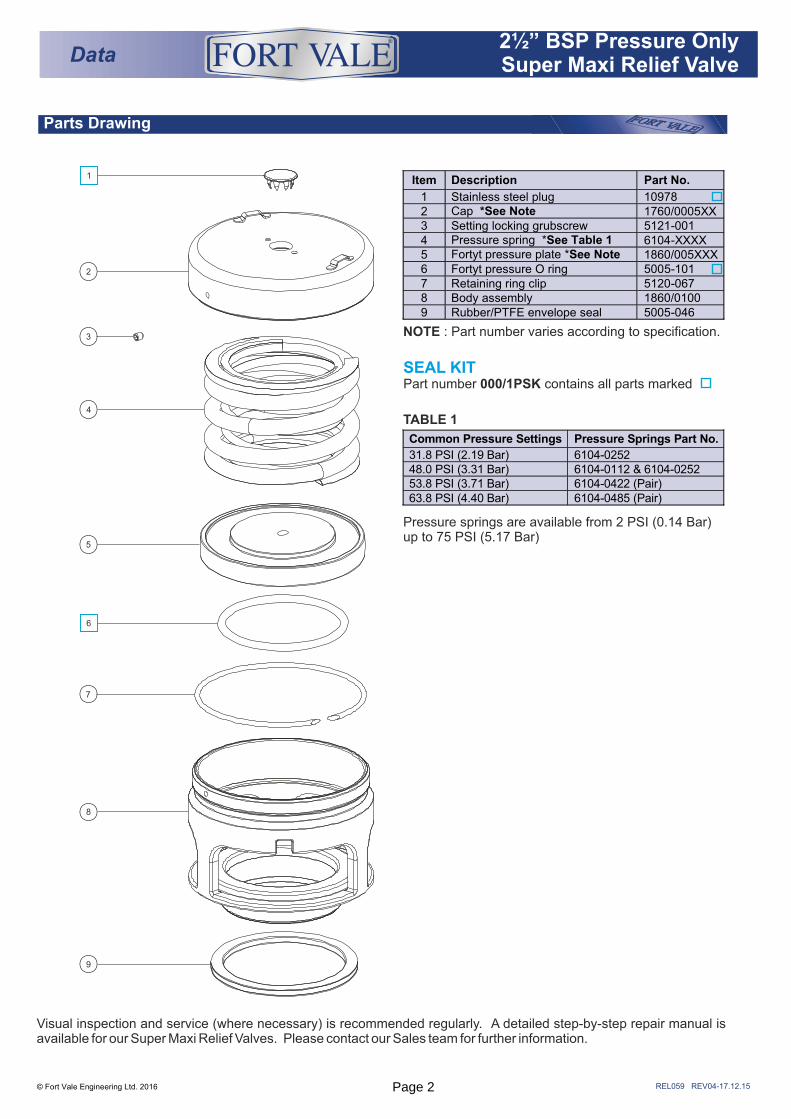
Parts Drawing
REL059 REV04-17.12.15© Fort Vale Engineering Ltd. 2016
SEAL KIT Part number 000/1PSK contains all parts marked
NOTE : Part number varies according to specification.
TABLE 1
Pressure springs are available from 2 PSI (0.14 Bar) up to 75 PSI (5.17 Bar)
Data® 2½” BSP Pressure Only
Super Maxi Relief Valve
1
2
3
4
5
6
7
8
9
Item Description Part No.
1 Stainless steel plug 10978 2 Cap *See Note 1760/0005XX 3 Setting locking grubscrew 5121-001 4 Pressure spring *See Table 1 6104-XXXX 5 Fortyt pressure plate *See Note 1860/005XXX 6 Fortyt pressure O ring 5005-101 7 Retaining ring clip 5120-067 8 Body assembly 1860/0100 9 Rubber/PTFE envelope seal 5005-046
Common Pressure Settings Pressure Springs Part No.
31.8 PSI (2.19 Bar) 6104-0252 48.0 PSI (3.31 Bar) 6104-0112 & 6104-0252 53.8 PSI (3.71 Bar) 6104-0422 (Pair) 63.8 PSI (4.40 Bar) 6104-0485 (Pair)
Visual inspection and service (where necessary) is recommended regularly. A detailed step-by-step repair manual is available for our Super Maxi Relief Valves. Please contact our Sales team for further information.
Page 2
Range
REL009 REV03-19.11.15
Fitting Details
Example shown : 010/1XXXX
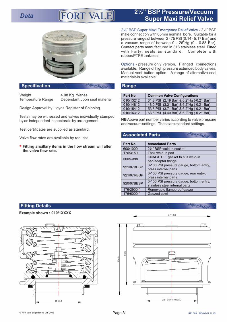
2½” BSP Super Maxi Emergency Relief Valve - 2½” BSP male connection with 65mm nominal bore. Suitable for a pressure range of between 2 - 75 PSI (0.14 - 5.17 Bar) and a vacuum range of between 0 - 26”Hg (0 - 0.88 Bar). Contact parts manufactured in 316 stainless steel. Fitted with Fortyt seals as standard. Complete with rubber/PTFE tank seal.
Options - pressure only version. Flanged connections available. Range of high pressure extended body valves. Manual vent button option. A range of alternative seal materials is available.
Specification
Associated Parts
NB Above part number varies according to valve pressure and vacuum settings. These are standard settings.
Part No. Common Valve Configurations
010/13212 31.8 PSI (2.19 Bar) & 6.2”Hg (-0.21 Bar) 010/14812 48.0 PSI (3.31 Bar) & 6.2”Hg (-0.21 Bar) 010/15412 53.8 PSI (3.71 Bar) & 6.2”Hg (-0.21 Bar) 010/16312 63.8 PSI (4.40 Bar) & 6.2”Hg (-0.21 Bar)
Data® 2½” BSP Pressure/Vacuum
Super Maxi Relief Valve
®
© Fort Vale Engineering Ltd. 2016
Weight 4.08 Kg *VariesTemperature Range Dependant upon seal material
Design Approval by Lloyds Register of Shipping.
Tests may be witnessed and valves individually stamped by an independent inspectorate by arrangement.
Test certificates are supplied as standard.
Valve flow rates are available by request.
Fitting ancillary items in the flow stream will alter the valve flow rate.*
Ø 68.1
Ø 113.8
2.5" BSP THREAD
89.9
104.9
Part No. Associated Parts
600/1000 2½” BSP weld-in socket 176/3150 Tank weld-in pad
5005-398 CNAF/PTFE gasket to suit weld-in pad/adaptor flange
921/07BBSP 0-100 PSI pressure gauge, bottom entry, brass internal parts
921/07RBSP 0-100 PSI pressure gauge, rear entry, brass internal parts
920/07BBSP 0-100 PSI pressure gauge, bottom entry, stainless steel internal parts
176/2900 * Removable flameproof gauze 176/6000 * Gauzed cowl
Page 3
Parts drawing
REL030 REV04-20.11.15
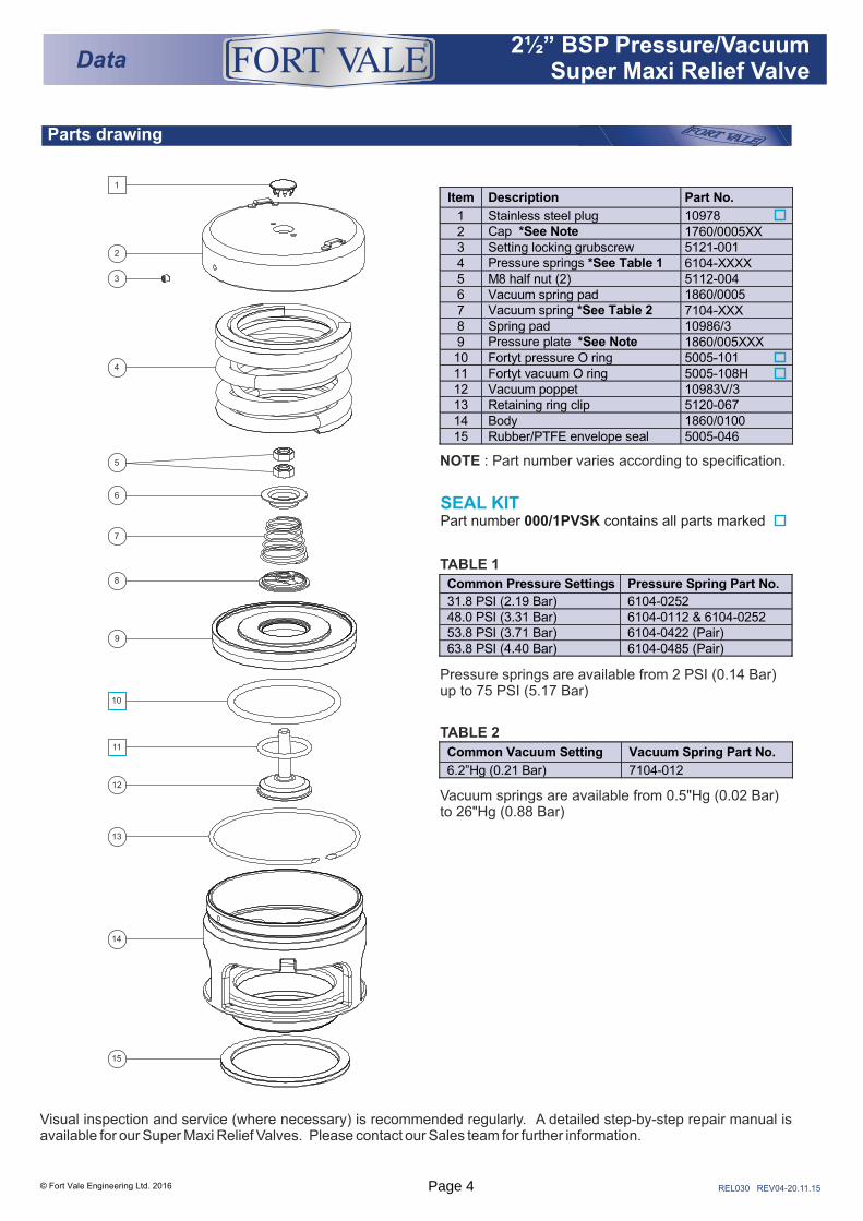
SEAL KITPart number 000/1PVSK contains all parts marked
© Fort Vale Engineering Ltd. 2016
NOTE : Part number varies according to specification.
Data® 2½” BSP Pressure/Vacuum
Super Maxi Relief Valve
®
TABLE 1
TABLE 2
Vacuum springs are available from 0.5"Hg (0.02 Bar) to 26"Hg (0.88 Bar)
Pressure springs are available from 2 PSI (0.14 Bar) up to 75 PSI (5.17 Bar)
10
11
2
3
4
5
6
7
8
9
12
13
14
15
1
Item Description Part No.
1 Stainless steel plug 10978 2 Cap *See Note 1760/0005XX 3 Setting locking grubscrew 5121-001 4 Pressure springs *See Table 1 6104-XXXX 5 M8 half nut (2) 5112-004 6 Vacuum spring pad 1860/0005 7 Vacuum spring *See Table 2 7104-XXX 8 Spring pad 10986/3 9 Pressure plate *See Note 1860/005XXX 10 Fortyt pressure O ring 5005-101 11 Fortyt vacuum O ring 5005-108H 12 Vacuum poppet 10983V/3 13 Retaining ring clip 5120-067 14 Body 1860/0100 15 Rubber/PTFE envelope seal 5005-046
Common Vacuum Setting Vacuum Spring Part No.
6.2”Hg (0.21 Bar) 7104-012
Common Pressure Settings Pressure Spring Part No.
31.8 PSI (2.19 Bar) 6104-0252 48.0 PSI (3.31 Bar) 6104-0112 & 6104-0252 53.8 PSI (3.71 Bar) 6104-0422 (Pair) 63.8 PSI (4.40 Bar) 6104-0485 (Pair)
Visual inspection and service (where necessary) is recommended regularly. A detailed step-by-step repair manual is available for our Super Maxi Relief Valves. Please contact our Sales team for further information.
Page 4
REL017 REV02- 17.12.15
Range
Associated Parts
1
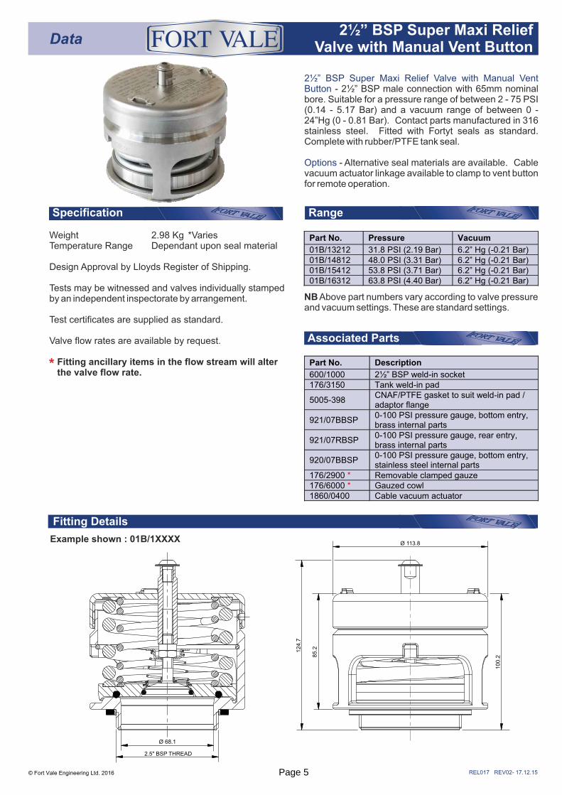
2½” BSP Super Maxi Relief Valve with Manual Vent Button - 2½” BSP male connection with 65mm nominal bore. Suitable for a pressure range of between 2 - 75 PSI (0.14 - 5.17 Bar) and a vacuum range of between 0 - 24”Hg (0 - 0.81 Bar). Contact parts manufactured in 316 stainless steel. Fitted with Fortyt seals as standard. Complete with rubber/PTFE tank seal.
Options - Alternative seal materials are available. Cable vacuum actuator linkage available to clamp to vent button for remote operation.
Specification
Fitting Details
Example shown : 01B/1XXXX
NB Above part numbers vary according to valve pressure and vacuum settings. These are standard settings.
© Fort Vale Engineering Ltd. 2016
Data2½” BSP Super Maxi Relief
Valve with Manual Vent Button
®
Weight 2.98 Kg *VariesTemperature Range Dependant upon seal material
Design Approval by Lloyds Register of Shipping.
Tests may be witnessed and valves individually stamped by an independent inspectorate by arrangement.
Test certificates are supplied as standard.
Valve flow rates are available by request.
Fitting ancillary items in the flow stream will alter the valve flow rate.*
2.5" BSP THREAD
Ø 68.1
124.7
85.2
Ø 113.8
100.2
Part No. Pressure Vacuum
01B/13212 31.8 PSI (2.19 Bar) 6.2” Hg (-0.21 Bar) 01B/14812 48.0 PSI (3.31 Bar) 6.2” Hg (-0.21 Bar) 01B/15412 53.8 PSI (3.71 Bar) 6.2” Hg (-0.21 Bar) 01B/16312 63.8 PSI (4.40 Bar) 6.2” Hg (-0.21 Bar)
Part No. Description
600/1000 2½” BSP weld-in socket 176/3150 Tank weld-in pad
5005-398 CNAF/PTFE gasket to suit weld-in pad / adaptor flange
921/07BBSP 0-100 PSI pressure gauge, bottom entry, brass internal parts
921/07RBSP 0-100 PSI pressure gauge, rear entry, brass internal parts
920/07BBSP 0-100 PSI pressure gauge, bottom entry, stainless steel internal parts
176/2900 * Removable clamped gauze 176/6000 * Gauzed cowl 1860/0400 Cable vacuum actuator
Page 5
REL034 REV04-17.12.15
Parts drawing
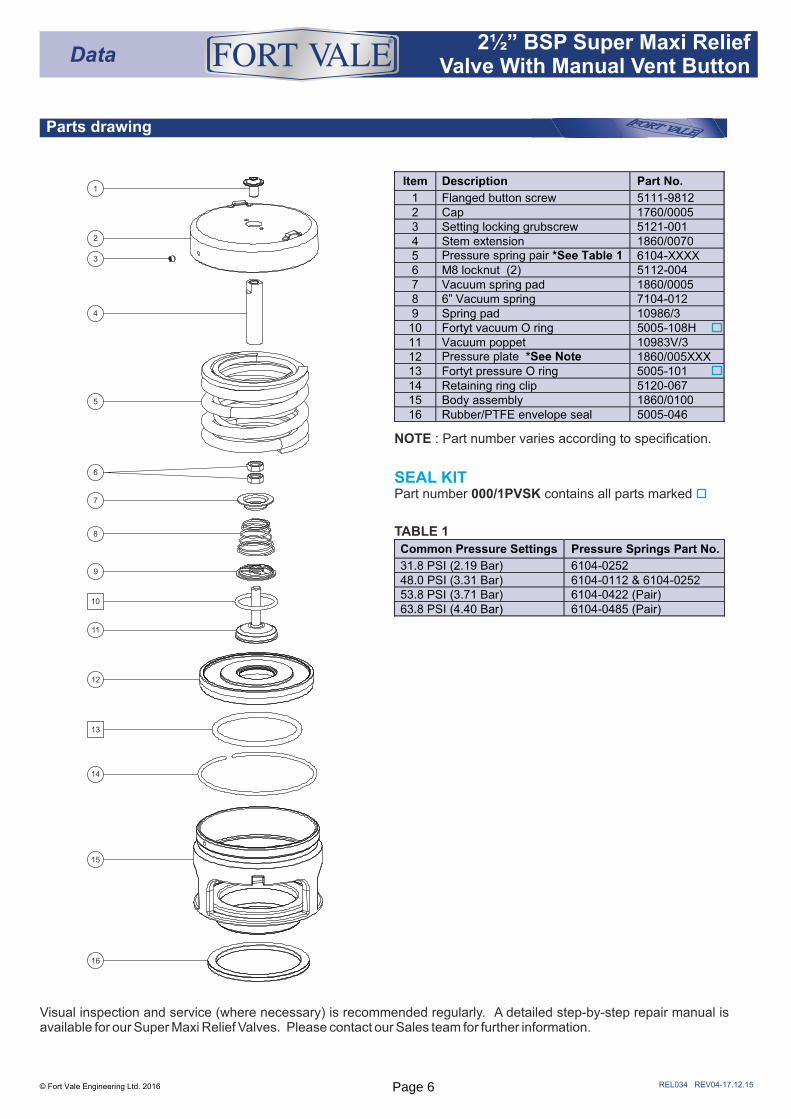
NOTE : Part number varies according to specification.
TABLE 1
© Fort Vale Engineering Ltd. 2016
1
2
3
4
5
6
7
8
9
11
12
14
15
16
13
10
Data2½” BSP Super Maxi Relief
Valve With Manual Vent Button
®
Visual inspection and service (where necessary) is recommended regularly. A detailed step-by-step repair manual is available for our Super Maxi Relief Valves. Please contact our Sales team for further information.
Common Pressure Settings Pressure Springs Part No.
31.8 PSI (2.19 Bar) 6104-0252 48.0 PSI (3.31 Bar) 6104-0112 & 6104-0252 53.8 PSI (3.71 Bar) 6104-0422 (Pair) 63.8 PSI (4.40 Bar) 6104-0485 (Pair)
SEAL KITPart number 000/1PVSK contains all parts marked
Item Description Part No.
1 Flanged button screw 5111-9812 2 Cap 1760/0005 3 Setting locking grubscrew 5121-001 4 Stem extension 1860/0070 5 Pressure spring pair *See Table 1 6104-XXXX 6 M8 locknut (2) 5112-004 7 Vacuum spring pad 1860/0005 8 6” Vacuum spring 7104-012 9 Spring pad 10986/3
10 Fortyt vacuum O ring 5005-108H 11 Vacuum poppet 10983V/3 12 Pressure plate *See Note 1860/005XXX 13 Fortyt pressure O ring 5005-101 14 Retaining ring clip 5120-067 15 Body assembly 1860/0100 16 Rubber/PTFE envelope seal 5005-046
Page 6
Data 2 " BSP Pressure Only Extended ½
Body Super Maxi Relief Valve
REL062 REV03-14.09.16
Range
Associated Parts
Example shown : 018/1XXX00
Fitting Details
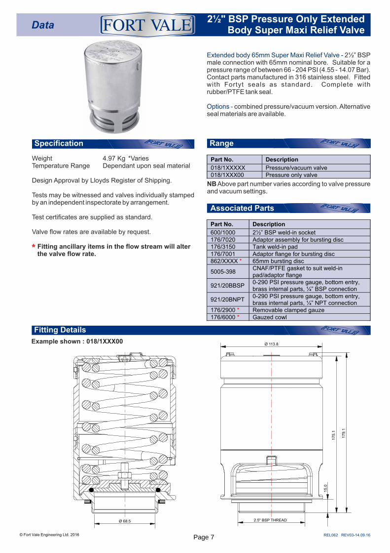
Extended body 65mm Super Maxi Relief Valve - 2½” BSP male connection with 65mm nominal bore. Suitable for a pressure range of between 66 - 204 PSI (4.55 - 14.07 Bar). Contact parts manufactured in 316 stainless steel. Fitted with Fortyt seals as standard. Complete with rubber/PTFE tank seal.
Options - combined pressure/vacuum version. Alternative seal materials are available.
Specification
© Fort Vale Engineering Ltd. 2016
Part No. Description
600/1000 2½” BSP weld-in socket 176/7020 Adaptor assembly for bursting disc 176/3150 Tank weld-in pad 176/7001 Adaptor flange for bursting disc 862/XXXX * 65mm bursting disc
5005-398 CNAF/PTFE gasket to suit weld-in pad/adaptor flange
921/20BBSP 0-290 PSI pressure gauge, bottom entry, brass internal parts, ¼” BSP connection
921/20BNPT 0-290 PSI pressure gauge, bottom entry, brass internal parts, ¼” NPT connection
176/2900 * Removable clamped gauze 176/6000 * Gauzed cowl
®
Weight 4.97 Kg *VariesTemperature Range Dependant upon seal material
Design Approval by Lloyds Register of Shipping.
Tests may be witnessed and valves individually stamped by an independent inspectorate by arrangement.
Test certificates are supplied as standard.
Valve flow rates are available by request.
Fitting ancillary items in the flow stream will alter the valve flow rate.*
NB Above part number varies according to valve pressure and vacuum settings.
Part No. Description
018/1XXXXX Pressure/vacuum valve 018/1XXX00 Pressure only valve
Ø 68.5
15.0
2.5" BSP THREAD
Ø 113.8
175.1
179.1
Page 7
Data
REL063 REV03-02.12.15
Parts drawing
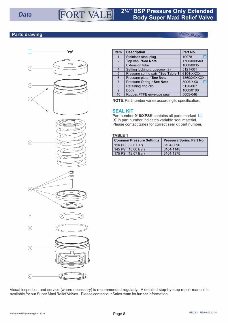
SEAL KITPart number 018/XPSK contains all parts marked‘X’ in part number indicates variable seal material. Please contact Sales for correct seal kit part number.
TABLE 1
© Fort Vale Engineering Ltd. 2016
Item Description Part No.
1 Stainless steel plug 10978 2 Top cap *See Note 1760/0005XX 3 Extension tube 1860/0035 4 Setting locking grubscrew (2) 5121-001 5 Pressure spring pair *See Table 1 6104-XXXX 6 Pressure plate *See Note 1860/X0XXXX 7 Pressure O ring *See Note 5005-XXX 8 Retaining ring clip 5120-067 9 Body 1860/0100
10 Rubber/PTFE envelope seal 5005-046
1
2
3
4
5
6
7
8
9
10
®
Common Pressure Settings Pressure Spring Part No.
116 PSI (8.00 Bar) 6104-0696 145 PSI (10.00 Bar) 6104-1145 175 PSI (12.07 Bar) 6104-1375
Visual inspection and service (where necessary) is recommended regularly. A detailed step-by-step repair manual is available for our Super Maxi Relief Valves. Please contact our Sales team for further information.
NOTE: Part number varies according to specification.
2 " BSP Pressure Only Extended ½Body Super Maxi Relief Valve
Page 8
REL018 REV03-14.09.16
Range
Associated Parts
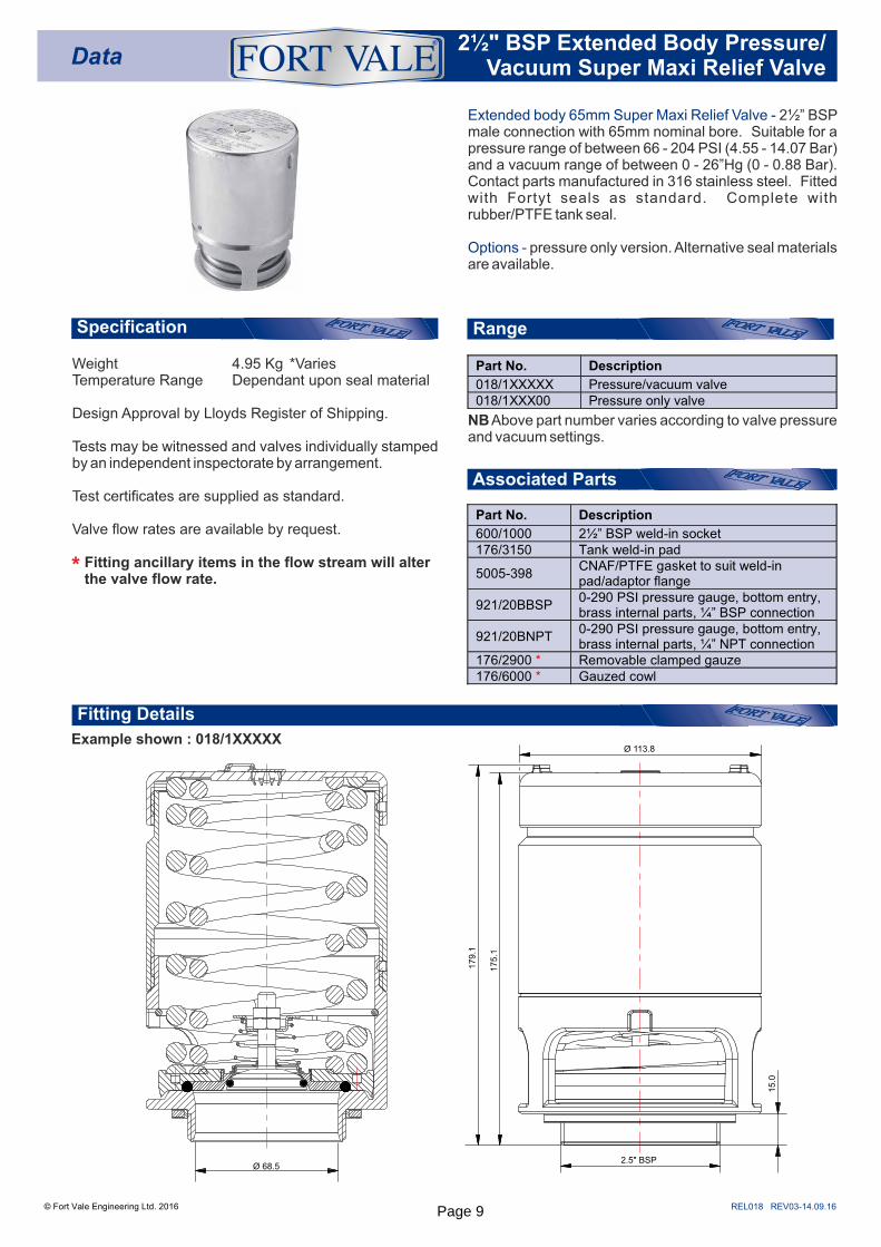
Example shown : 018/1XXXXX
Fitting Details
Extended body 65mm Super Maxi Relief Valve - 2½” BSP male connection with 65mm nominal bore. Suitable for a pressure range of between 66 - 204 PSI (4.55 - 14.07 Bar) and a vacuum range of between 0 - 26”Hg (0 - 0.88 Bar). Contact parts manufactured in 316 stainless steel. Fitted with Fortyt seals as standard. Complete with rubber/PTFE tank seal.
Options - pressure only version. Alternative seal materials are available.
Specification
© Fort Vale Engineering Ltd. 2016
Data®
Weight 4.95 Kg *VariesTemperature Range Dependant upon seal material
Design Approval by Lloyds Register of Shipping.
Tests may be witnessed and valves individually stamped by an independent inspectorate by arrangement.
Test certificates are supplied as standard.
Valve flow rates are available by request.
Fitting ancillary items in the flow stream will alter the valve flow rate.*
NB Above part number varies according to valve pressure and vacuum settings.
Part No. Description
018/1XXXXX Pressure/vacuum valve 018/1XXX00 Pressure only valve
2.5" BSP
Ø 113.8
175.1
179.1
15.0
Ø 68.5
Part No. Description
600/1000 2½” BSP weld-in socket 176/3150 Tank weld-in pad
5005-398 CNAF/PTFE gasket to suit weld-in pad/adaptor flange
921/20BBSP 0-290 PSI pressure gauge, bottom entry, brass internal parts, ¼” BSP connection
921/20BNPT 0-290 PSI pressure gauge, bottom entry, brass internal parts, ¼” NPT connection
176/2900 * Removable clamped gauze 176/6000 * Gauzed cowl
2 " BSP Extended Body Pressure/ ½Vacuum Super Maxi Relief Valve
Page 9
REL035 REV03- 06.01.16
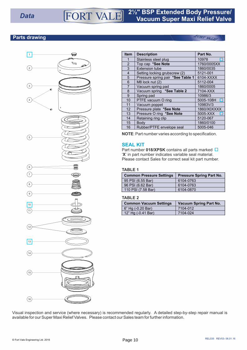
Parts drawing
© Fort Vale Engineering Ltd. 2016
16
2
3
4
5
6
7
8
9
11
12
14
15
1
10
13
Data®
TABLE 1
TABLE 2
Common Pressure Settings Pressure Spring Part No.
95 PSI (6.55 Bar) 6104-0763 96 PSI (6.62 Bar) 6104-0763 110 PSI (7.58 Bar) 6104-0870
Common Vacuum Settings Vacuum Spring Part No.
6” Hg (-0.20 Bar) 7104-012 12” Hg (-0.41 Bar) 7104-024
Visual inspection and service (where necessary) is recommended regularly. A detailed step-by-step repair manual is available for our Super Maxi Relief Valves. Please contact our Sales team for further information.
NOTE: Part number varies according to specification.
2 " BSP Extended Body Pressure/ ½Vacuum Super Maxi Relief Valve
Item Description Part No.
1 Stainless steel plug 10978 2 Top cap *See Note 1760/0005XX 3 Extension tube 1860/0035 4 Setting locking grubscrew (2) 5121-001 5 Pressure spring pair *See Table 1 6104-XXXX 6 M8 lock nut (2) 5112-004 7 Vacuum spring pad 1860/0005 8 Vacuum spring *See Table 2 7104-XXX 9 Spring pad 10986/3
10 PTFE vacuum O ring 5005-108H 11 Vacuum poppet 10983V/3 12 Pressure plate *See Note 1860/X0XXXX 13 Pressure O ring *See Note 5005-XXX 14 Retaining ring clip 5120-067 15 Body 1860/0100 16 Rubber/PTFE envelope seal 5005-046
SEAL KITPart number 018/XPSK contains all parts marked‘X’ in part number indicates variable seal material. Please contact Sales for correct seal kit part number.
Page 10
Range
Associated Parts
Data® 65mm Flanged Pressure Only
Super Maxi Relief Valve
Fitting Details
REL060 REV05-22.04.20
Specification
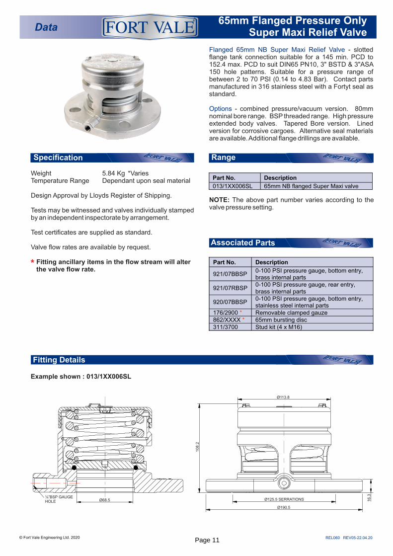
Flanged 65mm NB Super Maxi Relief Valve - slotted flange tank connection suitable for a 145 min. PCD to 152.4 max. PCD to suit DIN65 PN10, 3" BSTD & 3"ASA 150 hole patterns. Suitable for a pressure range of between 2 to 70 PSI (0.14 to 4.83 Bar). Contact parts manufactured in 316 stainless steel with a Fortyt seal as standard.
Options - combined pressure/vacuum version. 80mm nominal bore range. BSP threaded range. High pressure extended body valves. Tapered Bore version. Lined version for corrosive cargoes. Alternative seal materials are available. Additional flange drillings are available.
© Fort Vale Engineering Ltd. 2020
Example shown : 013/1XX006SL
Temperature Range Dependant upon seal materialWeight 5.84 Kg *Varies
the valve flow rate. Fitting ancillary items in the flow stream will alter
Valve flow rates are available by request.
Design Approval by Lloyds Register of Shipping.
Test certificates are supplied as standard.
Tests may be witnessed and valves individually stamped by an independent inspectorate by arrangement.
*
NOTE: The above part number varies according to the valve pressure setting.
Part No. Description
013/1XX006SL 65mm NB flanged Super Maxi valve
Part No. Description
921/07BBSP 0-100 PSI pressure gauge, bottom entry, brass internal parts
921/07RBSP 0-100 PSI pressure gauge, rear entry, brass internal parts
920/07BBSP 0-100 PSI pressure gauge, bottom entry, stainless steel internal parts
176/2900 * Removable clamped gauze 862/XXXX * 65mm bursting disc 311/3700 Stud kit (4 x M16)
Ø68.5¼”BSP GAUGE HOLE
Ø125.5 SERRATIONS
Ø113.8
108.2
Ø190.5
16.3
Page 11
REL061 REV05-22.04.20© Fort Vale Engineering Ltd. 2020
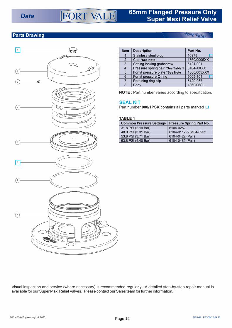
SEAL KITPart number 000/1PSK contains all parts marked
Parts Drawing
Data®
NOTE : Part number varies according to specification.
TABLE 1
Item Description Part No.
1 Stainless steel plug 10978 2 Cap *See Note 1760/0005XX 3 Setting locking grubscrew 5121-001 4 Pressure spring pair *See Table 1 6104-XXXX 5 Fortyt pressure plate *See Note 1860/005XXX 6 Fortyt pressure O ring 5005-101 7 Retaining ring clip 5120-067 8 Body 1860/06SL
Common Pressure Settings Pressure Spring Part No.
31.8 PSI (2.19 Bar) 6104-0252 48.0 PSI (3.31 Bar) 6104-0112 & 6104-0252 53.8 PSI (3.71 Bar) 6104-0422 (Pair) 63.8 PSI (4.40 Bar) 6104-0485 (Pair)
Visual inspection and service (where necessary) is recommended regularly. A detailed step-by-step repair manual is available for our Super Maxi Relief Valves. Please contact our Sales team for further information.
65mm Flanged Pressure Only Super Maxi Relief Valve
1
2
3
4
5
7
8
6
Page 12

Data® 65mm Flanged Pressure/Vacuum
Super Maxi Relief Valve
Fitting Details
REL010 REV05-22.04.20
Example shown : 013/1XXXX6SL
Flanged 65mm NB Super Maxi Relief Valve - slotted flange tank connection suitable for a 145 min. PCD to 152.4 max. PCD to suit DIN65 PN10, 3" BSTD & 3"ASA 150 hole patterns. Suitable for a pressure range of between 2 to 70 PSI (0.14 to 4.83 Bar) and a vacuum setting of between 0.5"Hg to 24”Hg (0.02 to 0.81 Bar). Contact parts manufactured in 316 stainless steel with Fortyt seals as standard.
Options - pressure only version. 80mm nominal bore range. BSP range. High pressure extended body valves. Tapered Bore version. Alternative seal materials are available. Additional flange drillings are available.
© Fort Vale Engineering Ltd. 2020
Associated Parts
RangeSpecification
Weight 6.94 Kg *Varies
Tests may be witnessed and valves individually stamped by an independent inspectorate by arrangement.
Temperature Range Dependant upon seal material
Test certificates are supplied as standard.
Design Approval by Lloyds Register of Shipping.
Valve flow rates are available by request.
the valve flow rate. Fitting ancillary items in the flow stream will alter *
NOTE: The above part number varies according to the valve pressure and vacuum settings.
Part No. Description
013/1XXXX6SL 65mm NB flanged Super Maxi valve
Part No. Description
921/07BBSP 0-100 PSI pressure gauge, bottom entry, brass internal parts
921/07RBSP 0-100 PSI pressure gauge, rear entry, brass internal parts
920/07BBSP 0-100 PSI pressure gauge, bottom entry, stainless steel internal parts
176/2900 * Removable clamped gauze 862/XXXX * 65mm bursting disc 311/3700 Stud kit (4 x M16)
Ø125.5 SERRATIONS
Ø113.8
108.2
Ø190.5
16.3
Ø68.5¼”BSP GAUGE HOLE
Page 13
Parts Drawing
REL031 REV04-22.04.20
NOTE : Part number varies according to specification.
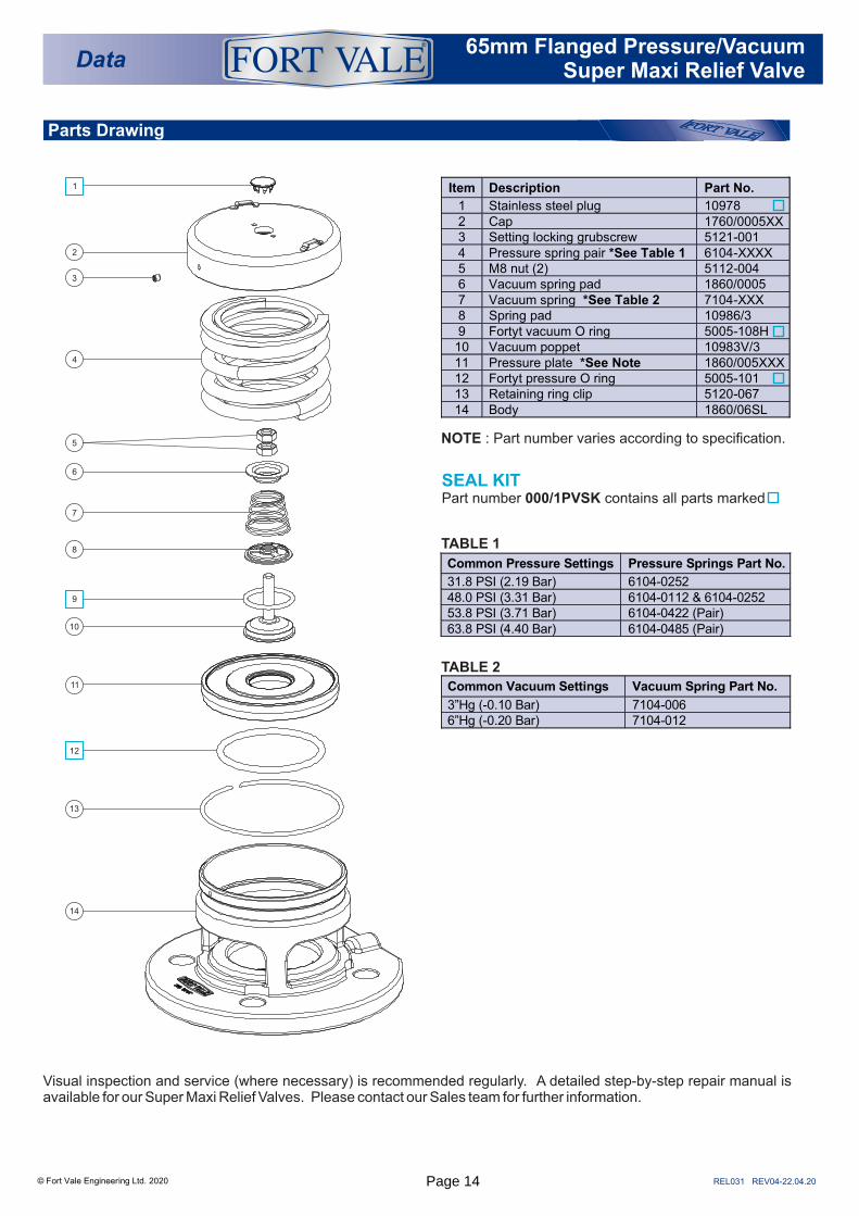
SEAL KITPart number 000/1PVSK contains all parts marked
© Fort Vale Engineering Ltd. 2020
Data®
TABLE 1
Common Pressure Settings Pressure Springs Part No.
31.8 PSI (2.19 Bar) 6104-0252 48.0 PSI (3.31 Bar) 6104-0112 & 6104-0252 53.8 PSI (3.71 Bar) 6104-0422 (Pair) 63.8 PSI (4.40 Bar) 6104-0485 (Pair)
Item Description Part No.
1 Stainless steel plug 10978 2 Cap 1760/0005XX 3 Setting locking grubscrew 5121-001 4 Pressure spring pair *See Table 1 6104-XXXX 5 M8 nut (2) 5112-004 6 Vacuum spring pad 1860/0005 7 Vacuum spring *See Table 2 7104-XXX 8 Spring pad 10986/3 9 Fortyt vacuum O ring 5005-108H
10 Vacuum poppet 10983V/3 11 Pressure plate *See Note 1860/005XXX 12 Fortyt pressure O ring 5005-101 13 Retaining ring clip 5120-067 14 Body 1860/06SL
Visual inspection and service (where necessary) is recommended regularly. A detailed step-by-step repair manual is available for our Super Maxi Relief Valves. Please contact our Sales team for further information.
65mm Flanged Pressure/Vacuum Super Maxi Relief Valve
TABLE 2
Common Vacuum Settings Vacuum Spring Part No.
3”Hg (-0.10 Bar) 7104-006 6”Hg (-0.20 Bar) 7104-012
1
7
2
3
4
5
6
8
12
11
9
10
13
14
Page 14
Data 65mm Pressure Only Extended Body
Flanged Super Maxi Relief Valve
Fitting Details
1
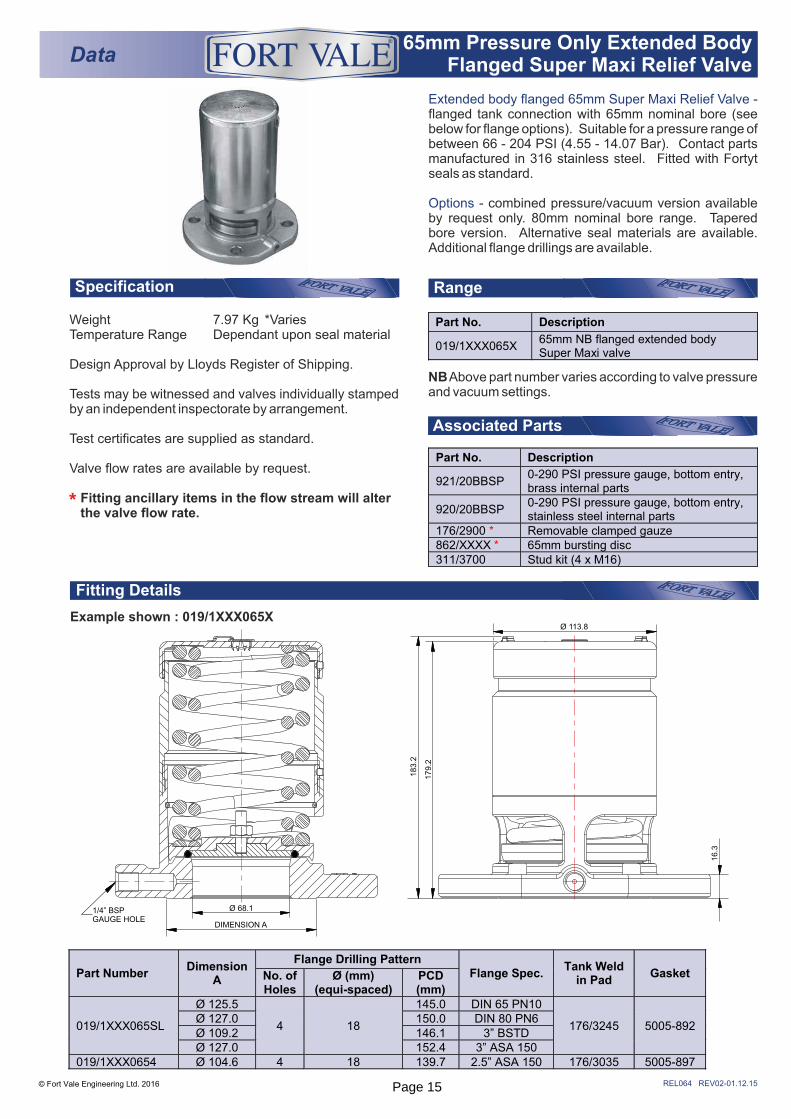
Extended body flanged 65mm Super Maxi Relief Valve - flanged tank connection with 65mm nominal bore (see below for flange options). Suitable for a pressure range of between 66 - 204 PSI (4.55 - 14.07 Bar). Contact parts manufactured in 316 stainless steel. Fitted with Fortyt seals as standard.
Options - combined pressure/vacuum version available by request only. 80mm nominal bore range. Tapered bore version. Alternative seal materials are available. Additional flange drillings are available.
RangeSpecification
Example shown : 019/1XXX065X
REL064 REV02-01.12.15© Fort Vale Engineering Ltd. 2016
Associated Parts
Part No. Description
921/20BBSP 0-290 PSI pressure gauge, bottom entry, brass internal parts
920/20BBSP 0-290 PSI pressure gauge, bottom entry, stainless steel internal parts
176/2900 * Removable clamped gauze 862/XXXX * 65mm bursting disc 311/3700 Stud kit (4 x M16)
®
Weight 7.97 Kg *VariesTemperature Range Dependant upon seal material
Design Approval by Lloyds Register of Shipping.
Tests may be witnessed and valves individually stamped by an independent inspectorate by arrangement.
Test certificates are supplied as standard.
Valve flow rates are available by request.
Fitting ancillary items in the flow stream will alter the valve flow rate.*
NB Above part number varies according to valve pressure and vacuum settings.
Part No. Description
019/1XXX065X 65mm NB flanged extended body Super Maxi valve
16.3
179.2
183.2
Ø 113.8
DIMENSION A
Ø 68.11/4” BSPGAUGE HOLE
Part Number Dimension
A
Flange Drilling Pattern Flange Spec.
Tank Weld in Pad
Gasket No. of Holes
Ø (mm) (equi-spaced)
PCD (mm)
019/1XXX065SL
Ø 125.5
4 18
145.0 DIN 65 PN10
176/3245 5005-892 Ø 127.0 150.0 DIN 80 PN6 Ø 109.2 146.1 3” BSTD Ø 127.0 152.4 3” ASA 150
019/1XXX0654 Ø 104.6 4 18 139.7 2.5” ASA 150 176/3035 5005-897
Page 15
REL065 REV02- 02.12.15
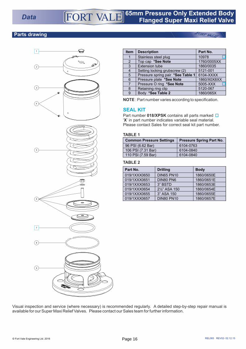
Parts drawing
1
TABLE 1
TABLE 2
© Fort Vale Engineering Ltd. 2016
Item Description Part No.
1 Stainless steel plug 10978 2 Top cap *See Note 1760/0005XX 3 Extension tube 1860/0035 4 Setting locking grubscrew (2) 5121-001 5 Pressure spring pair *See Table 1 6104-XXXX 6 Pressure plate *See Note 1860/X0X8XX 7 Pressure O ring *See Note 5005-XXX 8 Retaining ring clip 5120-067 9 Body *See Table 2 1860/065X
Visual inspection and service (where necessary) is recommended regularly. A detailed step-by-step repair manual is available for our Super Maxi Relief Valves. Please contact our Sales team for further information.
9
1
2
3
4
5
6
7
8
Data®
Common Pressure Settings Pressure Spring Part No.
96 PSI (6.62 Bar) 6104-0763
106 PSI (7.31 Bar) 6104-0840 110 PSI (7.59 Bar) 6104-0840
Part No. Drilling Body
019/1XXX0650 DIN65 PN10 1860/0650E
019/1XXX0651 DIN80 PN6 1860/0651E
019/1XXX0653 3” BSTD 1860/0653E
019/1XXX0654 2½” ASA 150 1860/0654E 019/1XXX0655 3” ASA 150 1860/0655E
019/1XXX0657 DIN80 PN10 1860/0657E
NOTE : Part number varies according to specification.
SEAL KITPart number 018/XPSK contains all parts marked‘X’ in part number indicates variable seal material. Please contact Sales for correct seal kit part number.
65mm Pressure Only Extended Body Flanged Super Maxi Relief Valve
Page 16
Range
Fitting Details
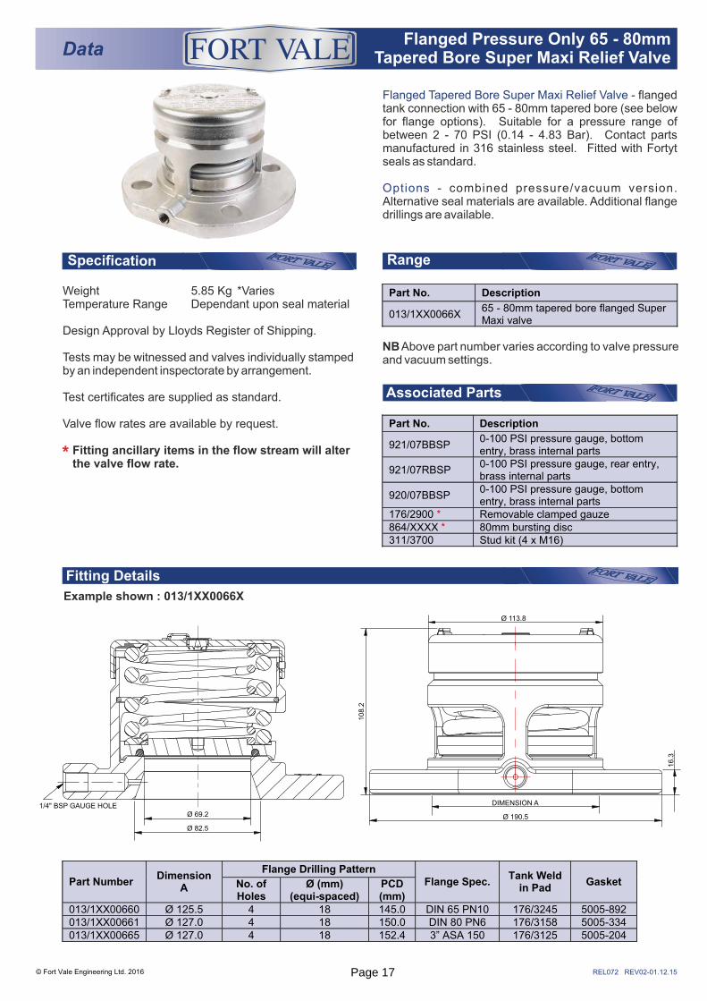
Example shown : 013/1XX0066X
Flanged Tapered Bore Super Maxi Relief Valve - flanged tank connection with 65 - 80mm tapered bore (see below for flange options). Suitable for a pressure range of between 2 - 70 PSI (0.14 - 4.83 Bar). Contact parts manufactured in 316 stainless steel. Fitted with Fortyt seals as standard.
Options - combined pressure/vacuum version. Alternative seal materials are available. Additional flange drillings are available.
© Fort Vale Engineering Ltd. 2016
Data® Flanged Pressure Only 65 - 80mm
Tapered Bore Super Maxi Relief Valve
Associated Parts
Specification
REL072 REV02-01.12.15
Part No. Description
921/07BBSP 0-100 PSI pressure gauge, bottom entry, brass internal parts
921/07RBSP 0-100 PSI pressure gauge, rear entry, brass internal parts
920/07BBSP 0-100 PSI pressure gauge, bottom entry, brass internal parts
176/2900 * Removable clamped gauze 864/XXXX * 80mm bursting disc 311/3700 Stud kit (4 x M16)
Weight 5.85 Kg *VariesTemperature Range Dependant upon seal material
Design Approval by Lloyds Register of Shipping.
Tests may be witnessed and valves individually stamped by an independent inspectorate by arrangement.
Test certificates are supplied as standard.
Valve flow rates are available by request.
Fitting ancillary items in the flow stream will alter the valve flow rate.*
NB Above part number varies according to valve pressure and vacuum settings.
Part Number Dimension
A
Flange Drilling Pattern Flange Spec.
Tank Weld in Pad
Gasket No. of Holes
Ø (mm) (equi-spaced)
PCD (mm)
013/1XX00660 Ø 125.5 4 18 145.0 DIN 65 PN10 176/3245 5005-892 013/1XX00661 Ø 127.0 4 18 150.0 DIN 80 PN6 176/3158 5005-334 013/1XX00665 Ø 127.0 4 18 152.4 3” ASA 150 176/3125 5005-204
Part No. Description
013/1XX0066X 65 - 80mm tapered bore flanged Super Maxi valve
Ø 69.2
Ø 82.5
1/4" BSP GAUGE HOLE
Ø 190.5
DIMENSION A
16.3
108.2
Ø 113.8
Page 17
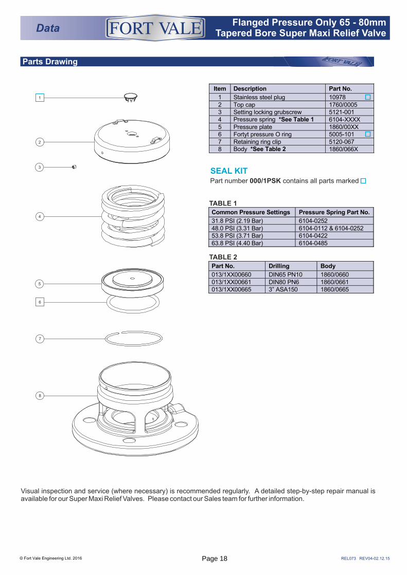
Parts Drawing
TABLE 1
TABLE 2
Part number 000/1PSK contains all parts marked
SEAL KIT
© Fort Vale Engineering Ltd. 2016
Data® Flanged Pressure Only 65 - 80mm
Tapered Bore Super Maxi Relief Valve
6
1
2
3
4
5
7
8
REL073 REV04-02.12.15
Item Description Part No.
1 Stainless steel plug 10978 2 Top cap 1760/0005 3 Setting locking grubscrew 5121-001 4 Pressure spring *See Table 1 6104-XXXX 5 Pressure plate 1860/00XX 6 Fortyt pressure O ring 5005-101 7 Retaining ring clip 5120-067 8 Body *See Table 2 1860/066X
Common Pressure Settings Pressure Spring Part No.
31.8 PSI (2.19 Bar) 6104-0252 48.0 PSI (3.31 Bar) 6104-0112 & 6104-0252 53.8 PSI (3.71 Bar) 6104-0422 63.8 PSI (4.40 Bar) 6104-0485
Part No. Drilling Body
013/1XX00660 DIN65 PN10 1860/0660 013/1XX00661 DIN80 PN6 1860/0661 013/1XX00665 3” ASA150 1860/0665
Visual inspection and service (where necessary) is recommended regularly. A detailed step-by-step repair manual is available for our Super Maxi Relief Valves. Please contact our Sales team for further information.
Page 18
Range
Associated Parts
Fitting Details
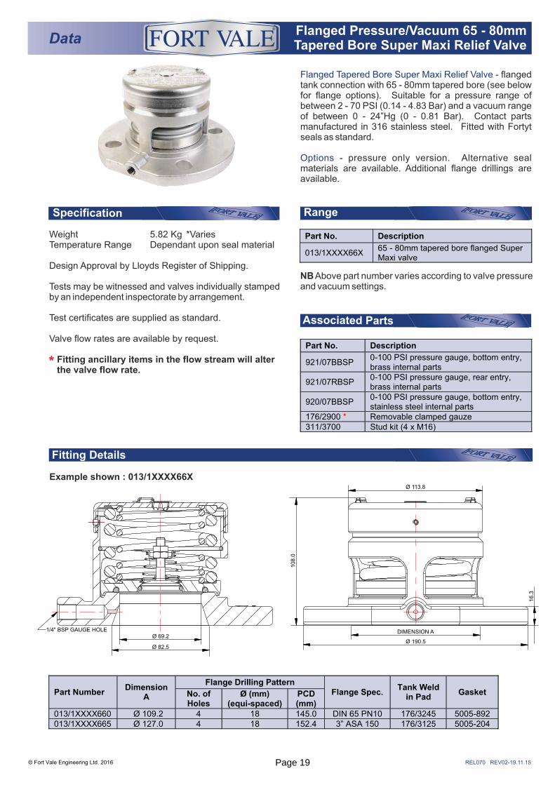
Example shown : 013/1XXXX66X
Specification
Flanged Tapered Bore Super Maxi Relief Valve - flanged tank connection with 65 - 80mm tapered bore (see below for flange options). Suitable for a pressure range of between 2 - 70 PSI (0.14 - 4.83 Bar) and a vacuum range of between 0 - 24”Hg (0 - 0.81 Bar). Contact parts manufactured in 316 stainless steel. Fitted with Fortyt seals as standard.
Options - pressure only version. Alternative seal materials are available. Additional flange drillings are available.
© Fort Vale Engineering Ltd. 2016
Data® Flanged Pressure/Vacuum 65 - 80mm
Tapered Bore Super Maxi Relief Valve
REL070 REV02-19.11.15
Weight 5.82 Kg *VariesTemperature Range Dependant upon seal material
Design Approval by Lloyds Register of Shipping.
Tests may be witnessed and valves individually stamped by an independent inspectorate by arrangement.
Test certificates are supplied as standard.
Valve flow rates are available by request.
Fitting ancillary items in the flow stream will alter the valve flow rate.*
NB Above part number varies according to valve pressure and vacuum settings.
Part No. Description
013/1XXXX66X 65 - 80mm tapered bore flanged Super Maxi valve
Part No. Description
921/07BBSP 0-100 PSI pressure gauge, bottom entry, brass internal parts
921/07RBSP 0-100 PSI pressure gauge, rear entry, brass internal parts
920/07BBSP 0-100 PSI pressure gauge, bottom entry, stainless steel internal parts
176/2900 * Removable clamped gauze 311/3700 Stud kit (4 x M16)
Part Number Dimension
A
Flange Drilling Pattern Flange Spec.
Tank Weld in Pad
Gasket No. of Holes
Ø (mm) (equi-spaced)
PCD (mm)
013/1XXXX660 Ø 109.2 4 18 145.0 DIN 65 PN10 176/3245 5005-892 013/1XXXX665 Ø 127.0 4 18 152.4 3” ASA 150 176/3125 5005-204
Ø 69.2
Ø 82.5
1/4" BSP GAUGE HOLE
Ø 190.5
DIMENSION A
16.3
108.0
Ø 113.8
Page 19
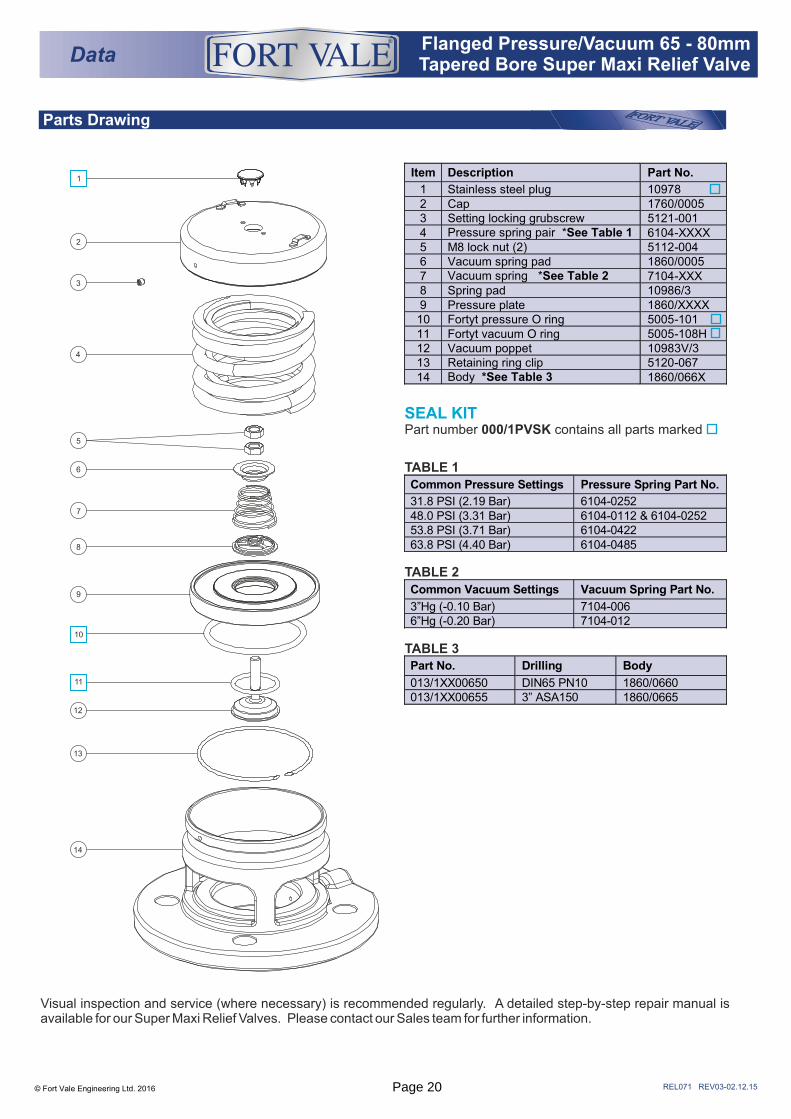
Parts Drawing
TABLE 1
TABLE 2
TABLE 3
© Fort Vale Engineering Ltd. 2016
Data® Flanged Pressure/Vacuum 65 - 80mm
Tapered Bore Super Maxi Relief Valve
REL071 REV03-02.12.15
Item Description Part No.
1 Stainless steel plug 10978 2 Cap 1760/0005 3 Setting locking grubscrew 5121-001 4 Pressure spring pair *See Table 1 6104-XXXX 5 M8 lock nut (2) 5112-004 6 Vacuum spring pad 1860/0005 7 Vacuum spring *See Table 2 7104-XXX 8 Spring pad 10986/3 9 Pressure plate 1860/XXXX 10 Fortyt pressure O ring 5005-101 11 Fortyt vacuum O ring 5005-108H 12 Vacuum poppet 10983V/3 13 Retaining ring clip 5120-067 14 Body *See Table 3 1860/066X
1
2
3
4
5
6
7
8
9
10
11
12
14
13
Visual inspection and service (where necessary) is recommended regularly. A detailed step-by-step repair manual is available for our Super Maxi Relief Valves. Please contact our Sales team for further information.
Common Pressure Settings Pressure Spring Part No.
31.8 PSI (2.19 Bar) 6104-0252 48.0 PSI (3.31 Bar) 6104-0112 & 6104-0252 53.8 PSI (3.71 Bar) 6104-0422 63.8 PSI (4.40 Bar) 6104-0485
Common Vacuum Settings Vacuum Spring Part No.
3”Hg (-0.10 Bar) 7104-006 6”Hg (-0.20 Bar) 7104-012
Part No. Drilling Body
013/1XX00650 DIN65 PN10 1860/0660 013/1XX00655 3” ASA150 1860/0665
SEAL KITPart number 000/1PVSK contains all parts marked
Page 20
Range
Associated Parts
Fitting Details
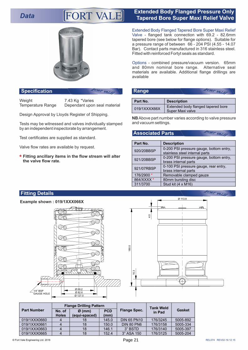
REL074 REV02-19.12.15
Example shown : 019/1XXX066X
Specification
Extended Body Flanged Tapered Bore Super Maxi Relief Valve - flanged tank connection with 69.2 - 82.6mm tapered bore (see below for flange options). Suitable for a pressure range of between 66 - 204 PSI (4.55 - 14.07 Bar). Contact parts manufactured in 316 stainless steel. Fitted with reinforced Fortyt seals as standard.
Options - combined pressure/vacuum version. 65mm and 80mm nominal bore range. Alternative seal materials are available. Additional flange drillings are available
Weight 7.43 Kg *VariesTemperature Range Dependant upon seal material
Design Approval by Lloyds Register of Shipping.
Tests may be witnessed and valves individually stamped by an independent inspectorate by arrangement.
Test certificates are supplied as standard.
Valve flow rates are available by request.
Fitting ancillary items in the flow stream will alter the valve flow rate.*
NB Above part number varies according to valve pressure and vacuum settings.
DataExtended Body Flanged Pressure Only Tapered Bore Super Maxi Relief Valve
®
© Fort Vale Engineering Ltd. 2016
Part No. Description
920/20BBSP 0-200 PSI pressure gauge, bottom entry, stainless steel internal parts
921/20BBSP 0-200 PSI pressure gauge, bottom entry, brass internal parts
921/07RBSP 0-100 PSI pressure gauge, rear entry, brass internal parts
176/2900 * Removable clamped gauze 864/XXXX * 80mm bursting disc 311/3700 Stud kit (4 x M16)
Part Number Flange Drilling Pattern
Flange Spec. Tank Weld
in Pad Gasket No. of
Holes Ø (mm)
(equi-spaced) PCD (mm)
019/1XXX0660 4 18 145.0 DIN 65 PN10 176/3245 5005-892 019/1XXX0661 4 18 150.0 DIN 80 PN6 176/3158 5005-334 019/1XXX0663 4 18 146.1 3” BSTD 176/3140 5005-397 019/1XXX0665 4 18 152.4 3” ASA 150 176/3125 5005-204
Ø 69.2
Ø 82.6
Ø 127.0
1/4” BSPGAUGE HOLE
16.3
180.0
Ø 113.8
4.0
Part No. Description
019/1XXXX66X Extended body flanged tapered bore Super Maxi valve
Page 21
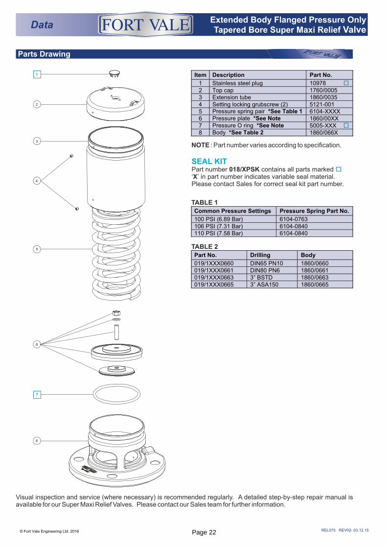
Parts Drawing
REL075 REV02- 03.12.15
SEAL KITPart number 018/XPSK contains all parts marked‘X’ in part number indicates variable seal material. Please contact Sales for correct seal kit part number.
© Fort Vale Engineering Ltd. 2016
Item Description Part No.
1 Stainless steel plug 10978 2 Top cap 1760/0005 3 Extension tube 1860/0035 4 Setting locking grubscrew (2) 5121-001 5 Pressure spring pair *See Table 1 6104-XXXX 6 Pressure plate *See Note 1860/00XX 7 Pressure O ring *See Note 5005-XXX 8 Body *See Table 2 1860/066X
1
2
3
4
5
6
7
8
DataExtended Body Flanged Pressure Only Tapered Bore Super Maxi Relief Valve
®
Visual inspection and service (where necessary) is recommended regularly. A detailed step-by-step repair manual is available for our Super Maxi Relief Valves. Please contact our Sales team for further information.
TABLE 1
TABLE 2
Common Pressure Settings Pressure Spring Part No.
100 PSI (6.89 Bar) 6104-0763 106 PSI (7.31 Bar) 6104-0840 110 PSI (7.58 Bar) 6104-0840
Part No. Drilling Body
019/1XXX0660 DIN65 PN10 1860/0660 019/1XXX0661 DIN80 PN6 1860/0661 019/1XXX0663 3” BSTD 1860/0663 019/1XXX0665 3” ASA150 1860/0665
NOTE : Part number varies according to specification.
Page 22
REL176 REV00-19.09.16© Fort Vale Engineering Ltd. 2016
Fitting Details
Associated Parts
De-rations
Drilling Details & FittingsSpecification
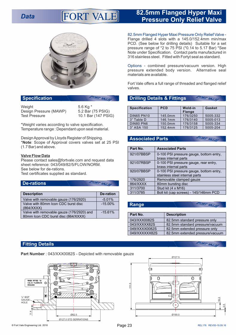
Data82.5mm Flanged Hyper Maxi
Pressure Only Relief Valve
®
82.5mm Flanged Hyper Maxi Pressure Only Relief Valve - Flange drilled 4 slots with a 145.0/152.4mm min/max PCD. (See below for drilling details) Suitable for a set pressure range of *2 to 75 PSI (*0.14 to 5.17 Bar) *See Note under Specification. Contact parts manufactured in 316 stainless steel. Fitted with Fortyt seal as standard.
Options - combined pressure/vacuum version. High pressure extended body version. Alternative seal materials are available.
Fort Vale offers a full range of threaded and flanged relief valves.
Weight 5.6 Kg *Design Pressure (MAWP) 5.2 Bar (75 PSIG)Test Pressure 10.1 Bar (147 PSIG)
*Weight varies according to valve specification.Temperature range : Dependant upon seal material.
Design Approval by Lloyds Register of Shipping.*Note: Scope of Approval covers valves set at 25 PSI (1.7 Bar) and above.
Valve Flow Data Please contact [email protected] and request data sheet reference: 043/049/82/5/FLOW/NORM. See below for de-rations.Test certificates supplied as standard.
Range
Specification PCD Weld-in Flange
Gasket
DIN65 PN10 145.0mm 176/3250 5005-332 3” Table D 146.1mm 176/3140 5005-013 DIN80 PN6 150.0mm 176/3158 5005-334 3” ASA 150 152.4mm 176/3125 5005-204
Part Number : 043/XXX0082S - Depicted with removable gauze
Part No. Description
043/XXX0082S 82.5mm standard pressure only 043/XXXXX82S 82.5mm standard pressure/vacuum 049/XXXX0082S 82.5mm extended pressure only 049/XXXXXX82S 82.5mm extended pressure/vacuum
Part No. Associated Parts
921/07BBSP 0-100 PSI pressure gauge, bottom entry, brass internal parts
921/07RBSP 0-100 PSI pressure gauge, rear entry, brass internal parts
920/07BBSP 0-100 PSI pressure gauge, bottom entry, stainless steel internal parts
176/2920 Removable clamped gauze 864/XXXX 80mm bursting disc 311/3700 Stud kit (4 x M16) 311/3785 Bolt kit (cap screws) - 145/146mm PCD
Description De-ration
Valve with removable gauze (176/2920) -5.01% Valve with 80mm Icon CDC burst disc (864/XXXX)
-15.00%
Valve with removable gauze (176/2920) and 80mm Icon CDC burst disc (864/XXXX)
-15.61%
Ø190.0
Ø127.5
111.5
16.3
0.5
Ø82.5
Ø127.0 STD SERRATIONS
11.4
¼” BSP GAUGE HOLE
Page 23
REL177 REV00-19.09.16
Parts drawing
© Fort Vale Engineering Ltd. 2016
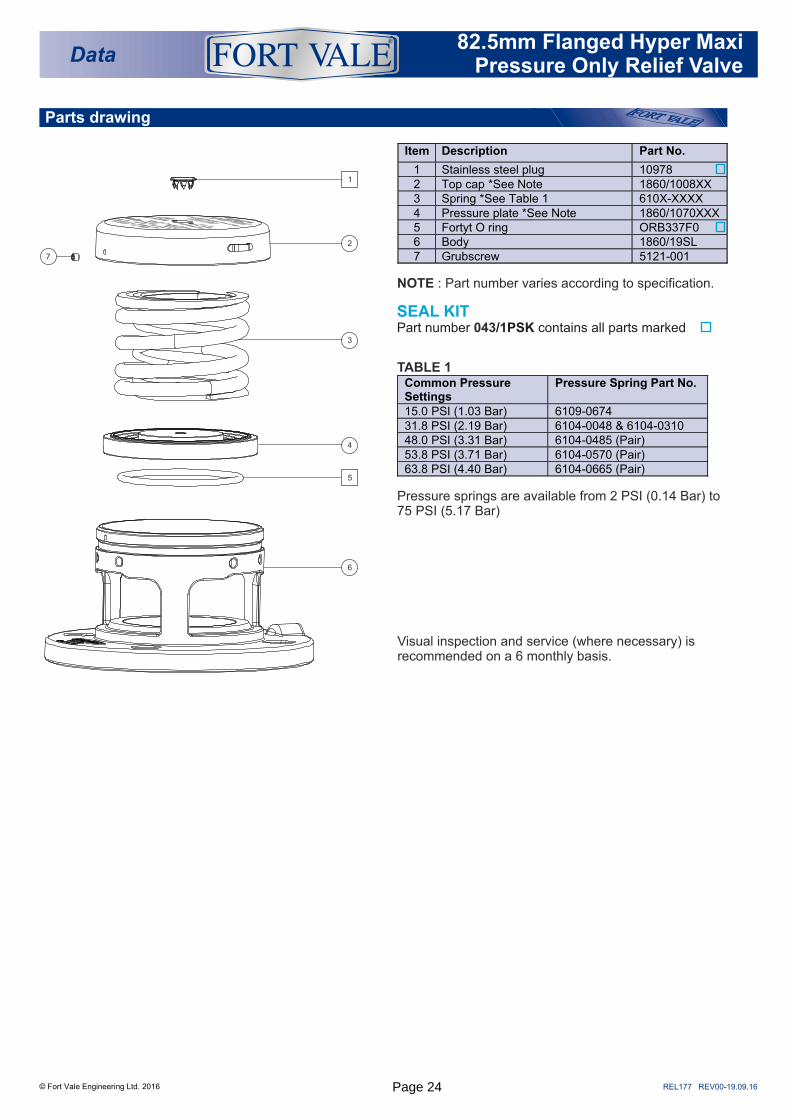
NOTE : Part number varies according to specification.
SEAL KITPart number /1PSK contains all parts marked 043
TABLE 1
Pressure springs are available from 2 PSI (0.14 Bar) to 75 PSI (5.17 Bar)
Visual inspection and service (where necessary) is recommended on a 6 monthly basis.
Data82.5mm Flanged Hyper Maxi
Pressure Only Relief Valve
®
Item Description Part No.
1 Stainless steel plug 10978 2 Top cap *See Note 1860/1008XX 3 Spring *See Table 1 610X-XXXX 4 Pressure plate *See Note 1860/1070XXX 5 Fortyt O ring ORB337F0 6 Body 1860/19SL 7 Grubscrew 5121-001
Common Pressure Settings
Pressure Spring Part No.
15.0 PSI (1.03 Bar) 6109-0674 31.8 PSI (2.19 Bar) 6104-0048 & 6104-0310 48.0 PSI (3.31 Bar) 6104-0485 (Pair) 53.8 PSI (3.71 Bar) 6104-0570 (Pair) 63.8 PSI (4.40 Bar) 6104-0665 (Pair)
1
2
3
4
5
6
7
Page 24

REL178 REV00-19.09.16
Fitting Details
Associated Parts
Drilling Details & FittingsSpecification
© Fort Vale Engineering Ltd. 2016
Data82.5mm Flanged Hyper Maxi
Pressure/Vacuum Relief Valve
®
82.5mm Flanged Hyper Maxi Pressure/Vacuum Relief Valve - Flange drilled 4 slots with a 145.0/152.4mm min/max PCD. (See below for drilling details) Suitable for a set pressure range of *2 to 75 PSI (*0.14 to 5.17 Bar) *See Note under Specification, and a set vacuum range of 0.5"Hg to 26"Hg (0.02 to 0.88 Bar). Contact parts manufactured in 316 stainless steel. Fitted with Fortyt seals as standard.
Options - pressure only version. High pressure extended body version. Alternative seal materials are available.
Fort Vale offers a full range of threaded and flanged relief valves.
Weight Kg *5.9 Design Pressure (MAWP) 5.2 Bar (75 PSIG)Test Pressure 10.1 Bar (147 PSIG)
*Weight varies according to valve specification.Temperature range : Dependant upon seal material.
Design Approval by Lloyds Register of Shipping.*Note: Scope of Approval covers valves set at 25 PSI (1.7 Bar) and above.
Valve Flow Data Please contact [email protected] and request data sheet reference: 043/049/82/5/FLOW/NORM. See below for de-rations.Test certificates supplied as standard.
Range
Specification PCD Weld-in Flange
Gasket
DIN65 PN10 145.0mm 176/3250 5005-332 3” Table D 146.1mm 176/3140 5005-013 DIN80 PN6 150.0mm 176/3158 5005-334 3” ASA 150 152.4mm 176/3125 5005-204
Part Number : 043/XXXXX82S - Depicted with removable gauze
Part No. Associated Parts
921/07BBSP 0-100 PSI pressure gauge, bottom entry, brass internal parts
921/07RBSP 0-100 PSI pressure gauge, rear entry, brass internal parts
920/07BBSP 0-100 PSI pressure gauge, bottom entry, stainless steel internal parts
176/2920 Removable clamped gauze 311/3700 Stud kit (4 x M16) 311/3785 Bolt kit (cap screws) - 145/146mm PCD
Part No. Description
043/XXX0082S 82.5mm standard pressure only 043/XXXXX82S 82.5mm standard pressure/vacuum 049/XXXX0082S 82.5mm extended pressure only 049/XXXXXX82S 82.5mm extended pressure/vacuum
De-rations
Description De-ration
Valve with removable gauze (176/2920) -5.01%
Ø190.0
Ø127.5
111.5
16.3
0.5
11.4
¼” BSP GAUGE HOLE
Ø82.5
Ø127.0 STD SERRATIONS
Page 25
REL179 REV00-19.09.16
Parts drawing
© Fort Vale Engineering Ltd. 2016
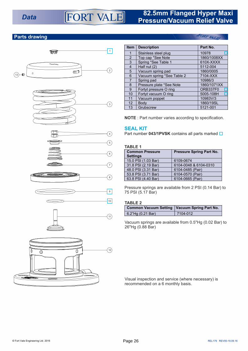
NOTE : Part number varies according to specification.
SEAL KITPart number /1PVSK contains all parts marked 043
TABLE 1
Pressure springs are available from 2 PSI (0.14 Bar) to 75 PSI (5.17 Bar)
Vacuum springs are available from 0.5"Hg (0.02 Bar) to 26"Hg (0.88 Bar)
Visual inspection and service (where necessary) is recommended on a 6 monthly basis.
TABLE 2 Common Vacuum Setting Vacuum Spring Part No.
6.2”Hg (0.21 Bar) 7104-012
Data82.5mm Flanged Hyper Maxi
Pressure/Vacuum Relief Valve
®
Item Description Part No.
1 Stainless steel plug 10978 2 Top cap *See Note 1860/1008XX 3 Spring *See Table 1 610X-XXXX 4 Half nut (2) 5112-004 5 Vacuum spring pad 1860/0005 6 Vacuum spring *See Table 2 7104-XXX 7 Spring pad 10986/3 8 Pressure plate *See Note 1860/1071XX 9 Fortyt pressure O ring ORB337F0
10 Fortyt vacuum O ring 5005-108H 11 Vacuum poppet 10983V/3 12 Body 1860/19SL 13 Grubscrew 5121-001
Common Pressure Settings
Pressure Spring Part No.
15.0 PSI (1.03 Bar) 6109-0674 31.8 PSI (2.19 Bar) 6104-0048 & 6104-0310 48.0 PSI (3.31 Bar) 6104-0485 (Pair) 53.8 PSI (3.71 Bar) 6104-0570 (Pair) 63.8 PSI (4.40 Bar) 6104-0665 (Pair)
1
2
3
4
5
6
7
9
8
10
11
12
13
Page 26
REL180 REV00-19.09.16
Fitting Details
Specification
© Fort Vale Engineering Ltd. 2016
Data82.5mm Flanged Extended Hyper
Maxi Pressure Only Relief Valve
®
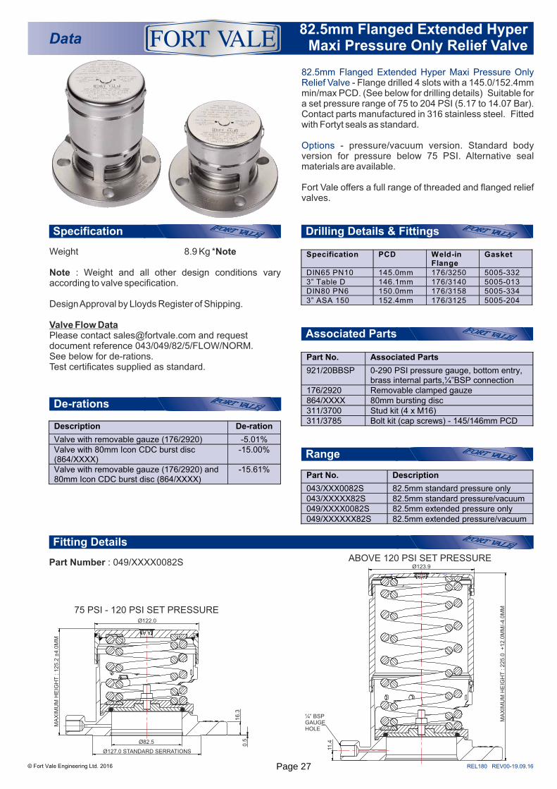
82.5mm Flanged Extended Hyper Maxi Pressure Only Relief Valve - Flange drilled 4 slots with a 145.0/152.4mm min/max PCD. (See below for drilling details) Suitable for a set pressure range of 75 to 204 PSI (5.17 to 14.07 Bar). Contact parts manufactured in 316 stainless steel. Fitted with Fortyt seals as standard.
Options - pressure/vacuum version. Standard body version for pressure below 75 PSI. Alternative seal materials are available.
Fort Vale offers a full range of threaded and flanged relief valves.
Weight 8.9 Kg *Note
Note : Weight and all other design conditions vary according to valve specification.
Design Approval by Lloyds Register of Shipping.
Valve Flow Data Please contact [email protected] and request document reference 043/049/82/5/FLOW/NORM. See below for de-rations.Test certificates supplied as standard.
Range
Part Number : 049/XXXX0082S
De-rations
Associated Parts
Part No. Associated Parts
921/20BBSP 0-290 PSI pressure gauge, bottom entry, brass internal parts,¼”BSP connection
176/2920 Removable clamped gauze 864/XXXX 80mm bursting disc 311/3700 Stud kit (4 x M16) 311/3785 Bolt kit (cap screws) - 145/146mm PCD
75 PSI - 120 PSI SET PRESSURE
ABOVE 120 PSI SET PRESSURE
Drilling Details & Fittings
Specification PCD Weld-in Flange
Gasket
DIN65 PN10 145.0mm 176/3250 5005-332 3” Table D 146.1mm 176/3140 5005-013 DIN80 PN6 150.0mm 176/3158 5005-334 3” ASA 150 152.4mm 176/3125 5005-204
Part No. Description
043/XXX0082S 82.5mm standard pressure only 043/XXXXX82S 82.5mm standard pressure/vacuum 049/XXXX0082S 82.5mm extended pressure only 049/XXXXXX82S 82.5mm extended pressure/vacuum
Description De-ration
Valve with removable gauze (176/2920) -5.01% Valve with 80mm Icon CDC burst disc (864/XXXX)
-15.00%
Valve with removable gauze (176/2920) and 80mm Icon CDC burst disc (864/XXXX)
-15.61%
Ø122.0
MA
XIM
UM
HE
IGH
T : 1
25.2
±4.0
MM
Ø82.5
Ø127.0 STANDARD SERRATIONS
0.5
16.3
Ø123.9
11.4
¼” BSPGAUGEHOLE
MA
XIM
UM
HE
IGH
T : 2
25.0
+
12.0
MM
/-4.0
MM
Page 27
REL181 REV00-19.09.16
Parts drawing
© Fort Vale Engineering Ltd. 2016
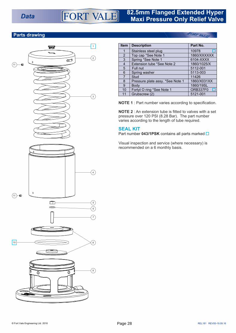
NOTE 1 : Part number varies according to specification.
NOTE 2 : An extension tube is fitted to valves with a set pressure over 120 PSI (8.28 Bar). The part number varies according to the length of tube required.
Visual inspection and service (where necessary) is recommended on a 6 monthly basis.
SEAL KITPart number /1PSK contains all parts marked 043
Data82.5mm Flanged Extended Hyper
Maxi Pressure Only Relief Valve
®
Item Description Part No.
1 Stainless steel plug 10978 2 Top cap *See Note 1 1860/XXXXXX 3 Spring *See Note 1 6104-XXXX 4 Extension tube *See Note 2 1860/1025/X 5 Full nut 5112-001 6 Spring washer 5113-003 7 Stud 11426 8 Pressure plate assy. *See Note 1 1860/X031XX 9 Body 1860/19SL
10 Fortyt O ring *See Note 1 ORB337F0 11 Grubscrew (2) 5121-001
2
1
3
4
810
9
5
7
6
11
11
Page 28

REL182 REV00-19.09.16
Fitting Details
Specification
© Fort Vale Engineering Ltd. 2016
Data82.5mm Flanged Extended Hyper
Maxi Pressure/Vacuum Relief Valve
®
82.5mm Flanged Extended Hyper Maxi Pressure/Vacuum Relief Valve - Flange drilled 4 slots with a 145.0/152.4mm min/max PCD. (See below for drilling details) Suitable for a set pressure range of 75 to 204 PSI (5.17 to 14.07 Bar) and a set vacuum range of 0.5"Hg to 24"Hg (0.02 to 0.81 Bar). Contact parts manufactured in 316 stainless steel. Fitted with Fortyt seals as standard.
Options - pressure only version. Standard body version for pressure below 75 PSI. Alternative seal materials are available.
Fort Vale offers a full range of threaded and flanged relief valves.
Weight 8.8 Kg *Note
Note : Weight and all other design conditions vary according to valve specification.
Design Approval by Lloyds Register of Shipping.
Valve Flow DataPlease contact [email protected] and request data sheet reference 043/049/82/5/FLOW/NORM. See below for de-rations.Test certificates supplied as standard.
Range
Drilling Details & Fittings
Specification PCD Weld-in Flange
Gasket
DIN65 PN10 145.0mm 176/3250 5005-332 3” Table D 146.1mm 176/3140 5005-013 DIN80 PN6 150.0mm 176/3158 5005-334 3” ASA 150 152.4mm 176/3125 5005-204
Part Number : 049/XXXXXX82S
75 PSI - 102 PSI SET PRESSURE
ABOVE 102 PSI SET PRESSURE
Part No. Description
043/XXX0082S 82.5mm standard pressure only 043/XXXXX82S 82.5mm standard pressure/vacuum 049/XXXX0082S 82.5mm extended pressure only 049/XXXXXX82S 82.5mm extended pressure/vacuum
De-rations
Description De-ration
Valve with removable gauze (176/2920) -5.01%
Associated Parts
Part No. Associated Parts
921/20BBSP 0-290 PSI pressure gauge, bottom entry, brass internal parts,¼”BSP connection
176/2920 Removable clamped gauze 311/3700 Stud kit (4 x M16) 311/3785 Bolt kit (cap screws) - 145/146mm PCD
0.5
16.3
Ø82.5
Ø127.0 STANDARD SERRATIONS
MA
XIM
UM
HE
IGH
T : 1
25.2
±4.0
MM
Ø122.0
Ø123.9
MA
XIM
UM
HE
IGH
T : 2
25.0
+
12.0
MM
/-4.0
MM
11.4
¼” BSPGAUGEHOLE
Page 29

REL183 REV00-19.09.16
Parts drawing
© Fort Vale Engineering Ltd. 2016
NOTE 1 : Part number varies according to specification.
NOTE 2 : An extension tube is fitted to valves with a set pressure over 102 PSI (7.03 Bar). The part number varies according to the length of tube required.
Visual inspection and service (where necessary) is recommended on a 6 monthly basis.
Service NotePlease note that there are 2 different designs of pressure plate assembly, depending upon the spring set pressure. A specialist tool is required to service pressure plate type 1860/X032XXTool part number : FIX/A/0010B
Please contact [email protected] for further maintenance information.
TABLE 1
Vacuum springs are available from 0.5"Hg (0.02 Bar) to 24"Hg (0.81 Bar)
Common Vacuum Setting Vacuum Spring Part No.
6.2”Hg (0.21 Bar) 7104-012
SEAL KITPart number /1PVSK contains all parts marked 043
Data82.5mm Flanged Extended Hyper
Maxi Pressure/Vacuum Relief Valve
®
Item Description Part No.
1 Stainless steel plug 10978 2 Top cap *See Note 1 1860/XXXXXX 3 Spring *See Note 1 6104-XXXX 4 Extension tube *See Note 2 1860/1025/X 5 M8 half nut (2) 5112-004 6 Vacuum spring pad 1860/0005 7 Vacuum spring *See Table 1 7104-XXX 8 Spring pad 10986/3 9 Pressure plate assy. *See Note 1 1860/X03XXX
10 Vacuum poppet 10983V/3 11 Fortyt vacuum O ring 5005-108H 12 Body *See Note 1 1860/19SL 13 Fortyt O ring *See Note 1 ORB337F0 14 Grubscrew (2) 5121-001
2
3
4
8
10
12
9
6
7
5
14
14
1
13
11
Page 30
REL151 REV00-27.03.15
Fitting Details
RangeSpecification
© Fort Vale Engineering Ltd. 2015
Data2½” Super Maxi Relief Valve -
80mm DIN11851
®
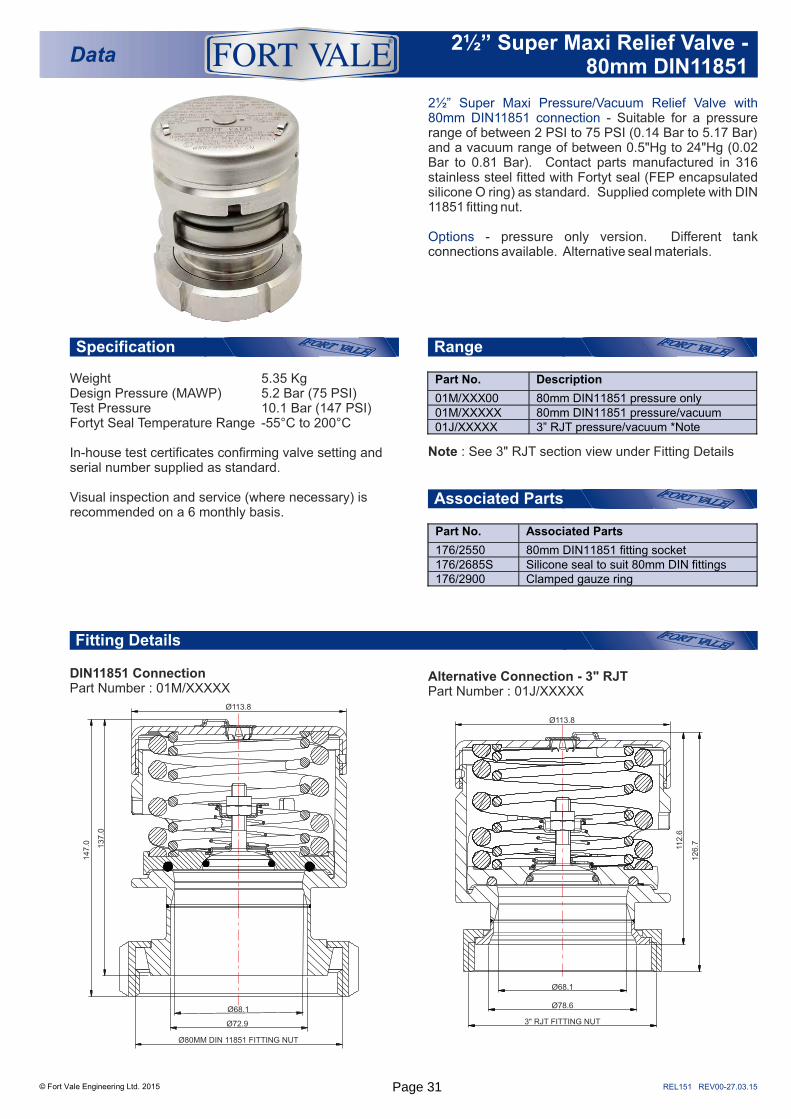
2½” Super Maxi Pressure/Vacuum Relief Valve with
Options
80mm DIN11851 connection - Suitable for a pressure range of between 2 PSI to 75 PSI (0.14 Bar to 5.17 Bar) and a vacuum range of between 0.5"Hg to 24"Hg (0.02 Bar to 0.81 Bar). Contact parts manufactured in 316 stainless steel fitted with Fortyt seal (FEP encapsulated silicone O ring) as standard. Supplied complete with DIN 11851 fitting nut.
- pressure only version. Different tank connections available. Alternative seal materials.
Weight 5.35 KgDesign Pressure (MAWP) 5.2 Bar (75 PSI)Test Pressure 10.1 Bar (147 PSI)Fortyt Seal Temperature Range -55°C to 200°C
In-house test certificates confirming valve setting and serial number supplied as standard.
Visual inspection and service (where necessary) is recommended on a 6 monthly basis.
Part No. Description
01M/XXX00 80mm DIN11851 pressure only 01M/XXXXX 80mm DIN11851 pressure/vacuum 01J/XXXXX 3” RJT pressure/vacuum *Note
DIN11851 ConnectionPart Number : 01M/XXXXX
Alternative Connection - Part Number : 01J/XXXXX
3" RJT
Associated Parts
Part No. Associated Parts
176/2550 80mm DIN11851 fitting socket 176/2685S Silicone seal to suit 80mm DIN fittings 176/2900 Clamped gauze ring
Ø113.8
Ø68.1
Ø78.6
3" RJT FITTING NUT
112.6
126.7
Ø113.8
137.0
147.0
Ø68.1
Ø72.9
Ø80MM DIN 11851 FITTING NUT
Note : See 3" RJT section view under Fitting Details
Page 31
REL152 REV00-27.03.15
Parts Drawing
© Fort Vale Engineering Ltd. 2015
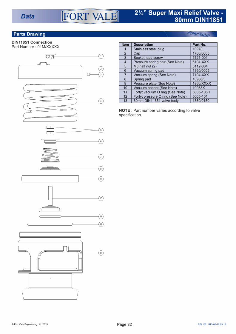
Item Description Part No. 1 Stainless steel plug 10978 2 Cap 1760/0005 3 Sockethead screw 5121-001 4 Pressure spring pair (See Note) 6104-XXX 5 M8 half nut (2) 5112-004 6 Vacuum spring pad 1860/0005 7 Vacuum spring (See Note) 7104-XXX 8 Spring pad 10986/3 9 Pressure plate (See Note) 1860/XXXX
10 Vacuum poppet (See Note) 10983X 11 Fortyt vacuum O ring (See Note) 5005-108H 12 Fortyt pressure O ring (See Note) 5005-101 13 80mm DIN11851 valve body 1860/0150
NOTE : Part number varies according to valve specification.
DIN11851 ConnectionPart Number : 01M/XXXXX
1
2
3
4
5
6
7
8
9
10
11
12
13
Data2½” Super Maxi Relief Valve -
80mm DIN11851
®
Page 32
REL099 REV02-17.12.15
Associated Parts
Fitting Details
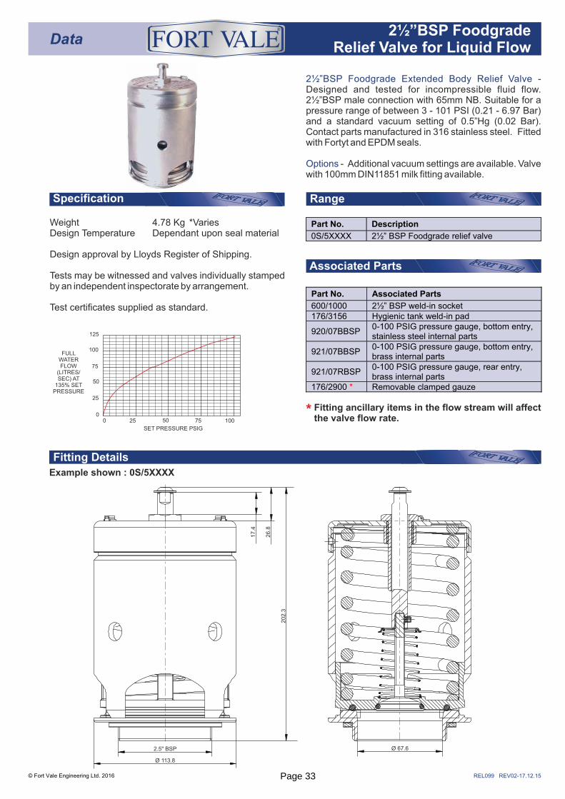
2½”BSP Foodgrade Extended Body Relief Valve - Designed and tested for incompressible fluid flow. 2½”BSP male connection with 65mm NB. Suitable for a pressure range of between 3 - 101 PSI (0.21 - 6.97 Bar) and a standard vacuum setting of 0.5”Hg (0.02 Bar). Contact parts manufactured in 316 stainless steel. Fitted with Fortyt and EPDM seals.
Options - Additional vacuum settings are available. Valve with 100mm DIN11851 milk fitting available.
RangeSpecification
Weight 4.78 Kg *VariesDesign Temperature Dependant upon seal material
Design approval by Lloyds Register of Shipping.
Tests may be witnessed and valves individually stamped by an independent inspectorate by arrangement.
Test certificates supplied as standard.
Example shown : 0S/5XXXX
© Fort Vale Engineering Ltd. 2016
Data® 2½”BSP Foodgrade
Relief Valve for Liquid Flow
Fitting ancillary items in the flow stream will affect the valve flow rate.*
Part No. Associated Parts
600/1000 2½” BSP weld-in socket 176/3156 Hygienic tank weld-in pad
920/07BBSP 0-100 PSIG pressure gauge, bottom entry, stainless steel internal parts
921/07BBSP 0-100 PSIG pressure gauge, bottom entry, brass internal parts
921/07RBSP 0-100 PSIG pressure gauge, rear entry, brass internal parts
176/2900 * Removable clamped gauze
Ø 67.62.5" BSP
Ø 113.8
202.3
17.4
26.8
Part No. Description
0S/5XXXX 2½” BSP Foodgrade relief valve
SET PRESSURE PSIG
FULL WATER FLOW
(LITRES/SEC) AT
135% SET PRESSURE
125
100
75
50
25
00 25 50 75 100
Page 33
REL100 REV02-17.12.15
Fitting Details
1
SEAL KITPart number 000/5PVSK contains all parts marked
TABLE 1
TABLE 2
© Fort Vale Engineering Ltd. 2016
1
2
3
4
5
6
7
10
12
13
9
8
11
4
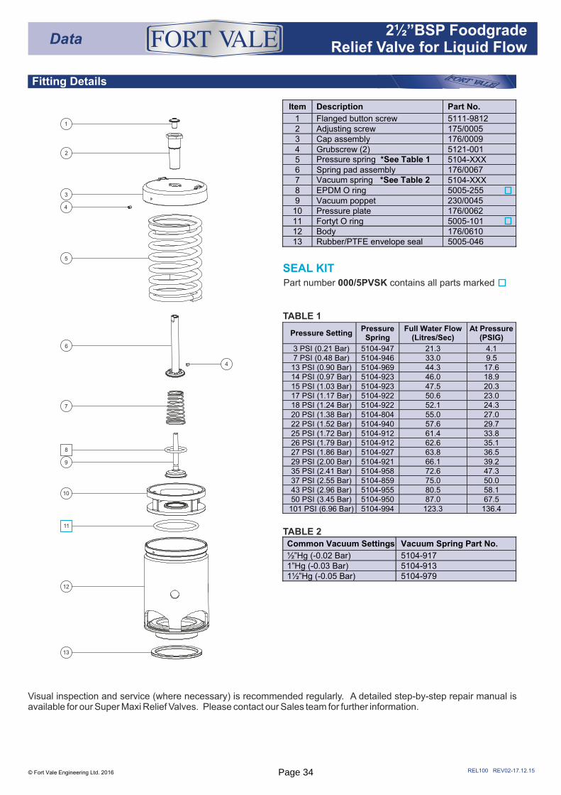
Item Description Part No.
1 Flanged button screw 5111-9812 2 Adjusting screw 175/0005 3 Cap assembly 176/0009 4 Grubscrew (2) 5121-001 5 Pressure spring *See Table 1 5104-XXX 6 Spring pad assembly 176/0067 7 Vacuum spring *See Table 2 5104-XXX 8 EPDM O ring 5005-255 9 Vacuum poppet 230/0045
10 Pressure plate 176/0062 11 Fortyt O ring 5005-101 12 Body 176/0610 13 Rubber/PTFE envelope seal 5005-046
Common Vacuum Settings Vacuum Spring Part No.
½”Hg (-0.02 Bar) 5104-917 1”Hg (-0.03 Bar) 5104-913 1½”Hg (-0.05 Bar) 5104-979
Data® 2½”BSP Foodgrade
Relief Valve for Liquid Flow
Pressure Setting Pressure
Spring Full Water Flow
(Litres/Sec) At Pressure
(PSIG)
3 PSI (0.21 Bar) 5104-947 21.3 4.1 7 PSI (0.48 Bar) 5104-946 33.0 9.5
13 PSI (0.90 Bar) 5104-969 44.3 17.6 14 PSI (0.97 Bar) 5104-923 46.0 18.9 15 PSI (1.03 Bar) 5104-923 47.5 20.3 17 PSI (1.17 Bar) 5104-922 50.6 23.0 18 PSI (1.24 Bar) 5104-922 52.1 24.3 20 PSI (1.38 Bar) 5104-804 55.0 27.0 22 PSI (1.52 Bar) 5104-940 57.6 29.7 25 PSI (1.72 Bar) 5104-912 61.4 33.8 26 PSI (1.79 Bar) 5104-912 62.6 35.1 27 PSI (1.86 Bar) 5104-927 63.8 36.5 29 PSI (2.00 Bar) 5104-921 66.1 39.2 35 PSI (2.41 Bar) 5104-958 72.6 47.3 37 PSI (2.55 Bar) 5104-859 75.0 50.0 43 PSI (2.96 Bar) 5104-955 80.5 58.1 50 PSI (3.45 Bar) 5104-950 87.0 67.5
101 PSI (6.96 Bar) 5104-994 123.3 136.4
Visual inspection and service (where necessary) is recommended regularly. A detailed step-by-step repair manual is available for our Super Maxi Relief Valves. Please contact our Sales team for further information.
Page 34
REL101 REV02-17.12.15
Associated Parts
Fitting Details
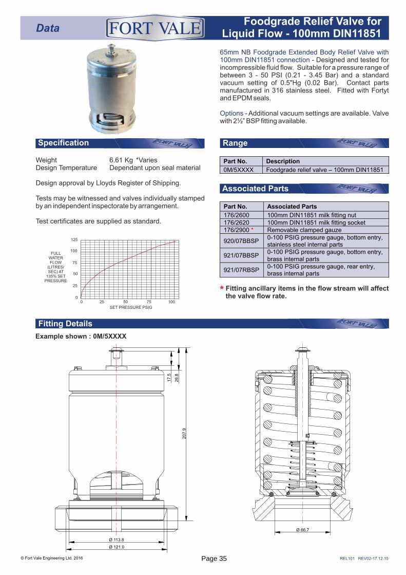
65mm NB Foodgrade Extended Body Relief Valve with 100mm DIN11851 connection - Designed and tested for incompressible fluid flow. Suitable for a pressure range of between 3 - 50 PSI (0.21 - 3.45 Bar) and a standard vacuum setting of 0.5"Hg (0.02 Bar). Contact parts manufactured in 316 stainless steel. Fitted with Fortyt and EPDM seals.
Options - Additional vacuum settings are available. Valve with 2½” BSP fitting available.
RangeSpecification
Weight 6.61 Kg *VariesDesign Temperature Dependant upon seal material
Design approval by Lloyds Register of Shipping.
Tests may be witnessed and valves individually stamped by an independent inspectorate by arrangement.
Test certificates are supplied as standard.
Example shown : 0M/5XXXX
Part No. Associated Parts
176/2600 100mm DIN11851 milk fitting nut 176/2620 100mm DIN11851 milk fitting socket 176/2900 * Removable clamped gauze
920/07BBSP 0-100 PSIG pressure gauge, bottom entry, stainless steel internal parts
921/07BBSP 0-100 PSIG pressure gauge, bottom entry, brass internal parts
921/07RBSP 0-100 PSIG pressure gauge, rear entry, brass internal parts
SET PRESSURE PSIG
FULL WATER FLOW
(LITRES/SEC) AT
135% SET PRESSURE
125
100
75
50
25
00 25 50 75 100
© Fort Vale Engineering Ltd. 2016
Fitting ancillary items in the flow stream will affect the valve flow rate.*
Ø 66.7
207.9
17.5
26.8
Ø 113.8
Ø 121.0
Part No. Description
0M/5XXXX Foodgrade relief valve – 100mm DIN11851
DataFoodgrade Relief Valve for
Liquid Flow - 100mm DIN11851
®
Page 35
REL102 REV02-17.12.15
Fitting Details
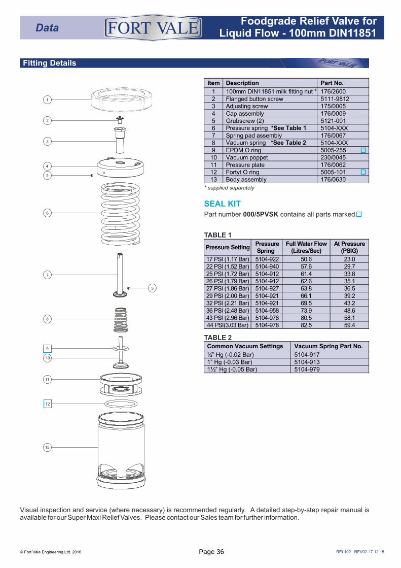
SEAL KITPart number 000/5PVSK contains all parts marked
* supplied separately
TABLE 2
© Fort Vale Engineering Ltd. 2016
1
2
3
4
5
5
6
7
8
11
13
12
10
9 Common Vacuum Settings Vacuum Spring Part No.
½” Hg (-0.02 Bar) 5104-917 1” Hg (-0.03 Bar) 5104-913 1½” Hg (-0.05 Bar) 5104-979
Item Description Part No.
1 100mm DIN11851 milk fitting nut * 176/2600 2 Flanged button screw 5111-9812 3 Adjusting screw 175/0005 4 Cap assembly 176/0009 5 Grubscrew (2) 5121-001 6 Pressure spring *See Table 1 5104-XXX 7 Spring pad assembly 176/0067 8 Vacuum spring *See Table 2 5104-XXX 9 EPDM O ring 5005-255 10 Vacuum poppet 230/0045 11 Pressure plate 176/0062 12 Fortyt O ring 5005-101 13 Body assembly 176/0630
DataFoodgrade Relief Valve for
Liquid Flow - 100mm DIN11851
®
TABLE 1
Visual inspection and service (where necessary) is recommended regularly. A detailed step-by-step repair manual is available for our Super Maxi Relief Valves. Please contact our Sales team for further information.
Pressure Setting Pressure Spring
Full Water Flow (Litres/Sec)
At Pressure (PSIG)
17 PSI (1.17 Bar) 5104-922 50.6 23.0 22 PSI (1.52 Bar) 5104-940 57.6 29.7 25 PSI (1.72 Bar) 5104-912 61.4 33.8 26 PSI (1.79 Bar) 5104-912 62.6 35.1 27 PSI (1.86 Bar) 5104-927 63.8 36.5 29 PSI (2.00 Bar) 5104-921 66.1 39.2 32 PSI (2.21 Bar) 5104-921 69.5 43.2 36 PSI (2.48 Bar) 5104-958 73.9 48.6 43 PSI (2.96 Bar) 5104-978 80.5 58.1 44 PSI(3.03 Bar) 5104-978 82.5 59.4
Page 36
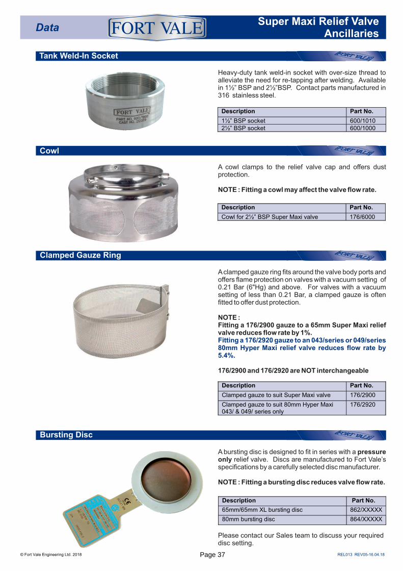
Tank Weld-In Socket
Clamped Gauze Ring
Cowl
Heavy-duty tank weld-in socket with over-size thread to alleviate the need for re-tapping after welding. Available in 1½” BSP and 2½”BSP. Contact parts manufactured in 316 stainless steel.
A cowl clamps to the relief valve cap and offers dust protection.
NOTE : Fitting a cowl may affect the valve flow rate.
A clamped gauze ring fits around the valve body ports and offers flame protection on valves with a vacuum setting of 0.21 Bar (6"Hg) and above. For valves with a vacuum setting of less than 0.21 Bar, a clamped gauze is often fitted to offer dust protection.
NOTE :Fitting a 176/2900 gauze to a 65mm Super Maxi relief valve reduces flow rate by 1%. Fitting a 176/2920 gauze to an 043/series or 049/series 80mm Hyper Maxi relief valve reduces flow rate by 5.4%.
176/2900 and 176/2920 are NOT interchangeable
Description Part No.
1½” BSP socket 600/1010 2½” BSP socket 600/1000
© Fort Vale Engineering Ltd. 2018
Description Part No.
Cowl for 2½” BSP Super Maxi valve 176/6000
DataSuper Maxi Relief Valve
Ancillaries
®
Bursting Disc
A bursting disc is designed to fit in series with a pressure only relief valve. Discs are manufactured to Fort Vale’s specifications by a carefully selected disc manufacturer. NOTE : Fitting a bursting disc reduces valve flow rate.
Please contact our Sales team to discuss your required disc setting.
Description Part No.
Clamped gauze to suit Super Maxi valve 176/2900
Clamped gauze to suit 80mm Hyper Maxi 043/ & 049/ series only
176/2920
Description Part No.
65mm/65mm XL bursting disc 862/XXXXX
80mm bursting disc 864/XXXXX
REL013 REV05-16.04.18Page 37
REL014 REV01-09.12.15
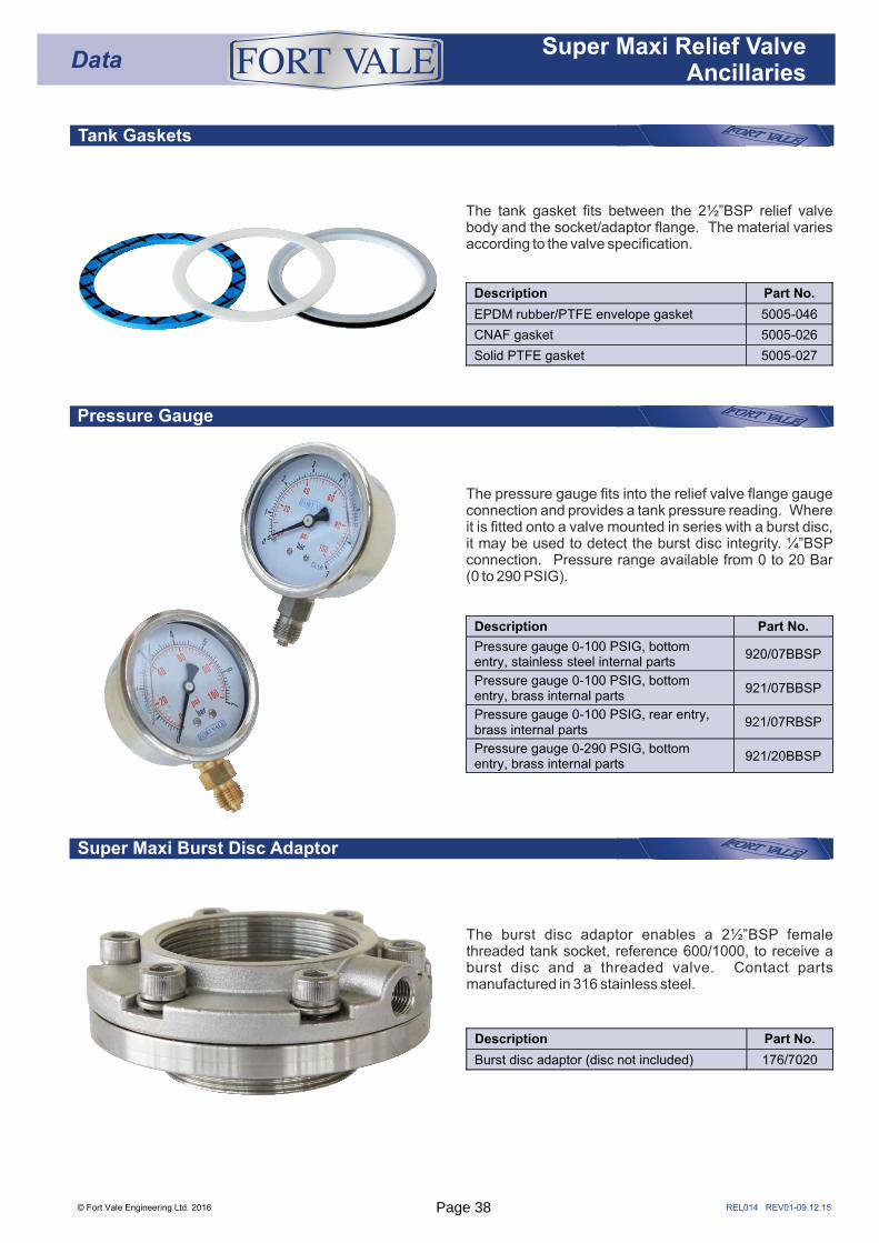
Tank Gaskets
Pressure Gauge
The pressure gauge fits into the relief valve flange gauge connection and provides a tank pressure reading. Where it is fitted onto a valve mounted in series with a burst disc, it may be used to detect the burst disc integrity. ¼”BSP connection. Pressure range available from 0 to 20 Bar (0 to 290 PSIG).
Super Maxi Burst Disc Adaptor
The burst disc adaptor enables a 2½”BSP female threaded tank socket, reference 600/1000, to receive a burst disc and a threaded valve. Contact parts manufactured in 316 stainless steel.
The tank gasket fits between the 2½”BSP relief valve body and the socket/adaptor flange. The material varies according to the valve specification.
DataSuper Maxi Relief Valve
Ancillaries
®
Description Part No.
EPDM rubber/PTFE envelope gasket 5005-046
CNAF gasket 5005-026
Solid PTFE gasket 5005-027
Description Part No.
Burst disc adaptor (disc not included) 176/7020
Description Part No.
Pressure gauge 0-100 PSIG, bottom entry, stainless steel internal parts
920/07BBSP
Pressure gauge 0-100 PSIG, bottom entry, brass internal parts
921/07BBSP
Pressure gauge 0-100 PSIG, rear entry, brass internal parts
921/07RBSP
Pressure gauge 0-290 PSIG, bottom entry, brass internal parts
921/20BBSP
© Fort Vale Engineering Ltd. 2016 Page 38
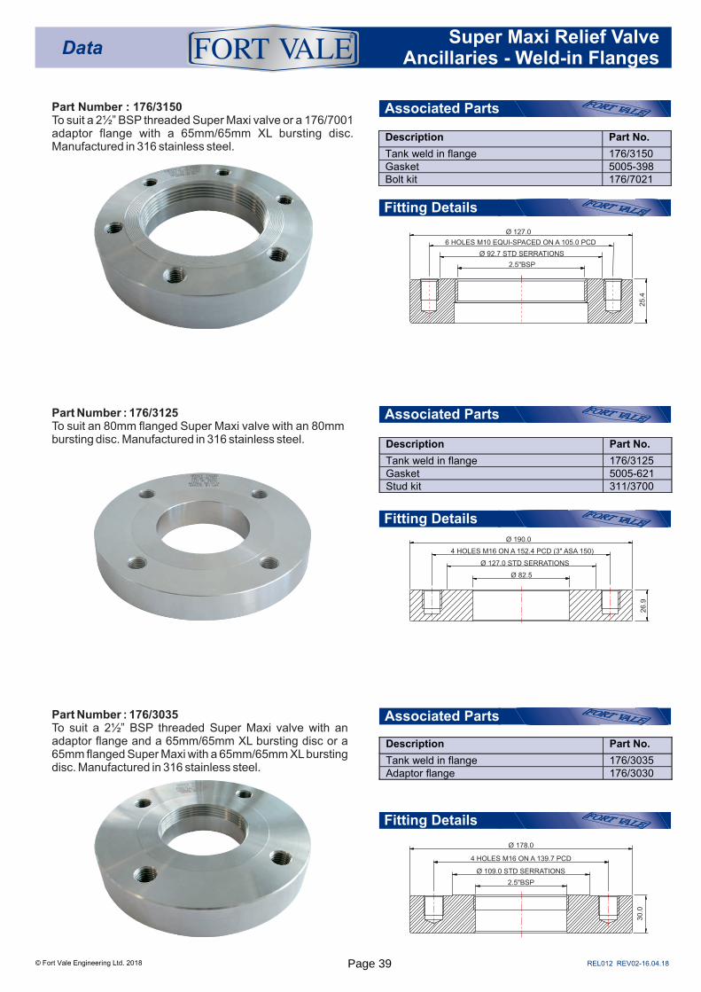
Part Number : 176/3125To suit an 80mm flanged Super Maxi valve with an 80mm bursting disc. Manufactured in 316 stainless steel.
Part Number : 176/3035To suit a 2½” BSP threaded Super Maxi valve with an adaptor flange and a 65mm/65mm XL bursting disc or a 65mm flanged Super Maxi with a 65mm/65mm XL bursting disc. Manufactured in 316 stainless steel.
Description Part No.
Tank weld in flange 176/3150Gasket 5005-398Bolt kit 176/7021
Description Part No.
Tank weld in flange 176/3125Gasket 5005-621Stud kit 311/3700
Description Part No.
Tank weld in flange 176/3035Adaptor flange 176/3030
© Fort Vale Engineering Ltd. 2018
Part Number : 176/3150To suit a 2½” BSP threaded Super Maxi valve or a 176/7001 adaptor flange with a 65mm/65mm XL bursting disc. Manufactured in 316 stainless steel.
DataSuper Maxi Relief Valve
Ancillaries - Weld-in Flanges
®
6 HOLES M10 EQUI-SPACED ON A 105.0 PCD
Ø 127.0
2.5"BSP
25.4
Ø 92.7 STD SERRATIONS
Associated Parts
Associated Parts
Associated Parts
Fitting Details
Fitting Details
Fitting Details
26.9
4 HOLES M16 ON A 152.4 PCD (3" ASA 150)
Ø 190.0
Ø 82.5
Ø 127.0 STD SERRATIONS
REL012 REV02-16.04.18
30
.0
4 HOLES M16 ON A 139.7 PCD
Ø 178.0
2.5"BSP
Ø 109.0 STD SERRATIONS
Page 39
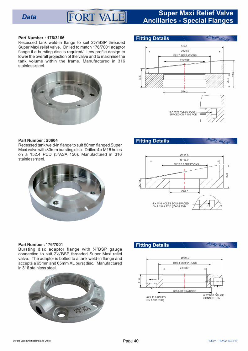
Part Number : 176/7001Bursting disc adaptor flange with ¼”BSP gauge connection to suit 2½”BSP threaded Super Maxi relief valve. The adaptor is bolted to a tank weld-in flange and accepts a 65mm and 65mm XL burst disc. Manufactured in 316 stainless steel.
© Fort Vale Engineering Ltd. 2018
Part Number : 176/3166Recessed tank weld-in flange to suit 2½”BSP threaded Super Maxi relief valve. Drilled to match 176/7001 adaptor flange if a bursting disc is required/ Low profile design to lower the overall projection of the valve and to maximise the tank volume within the frame. Manufactured in 316 stainless steel.
Part Number : S0604Recessed tank weld-in flange to suit 80mm flanged Super Maxi valve with 80mm bursting disc. Drilled 4 x M16 holes on a 152.4 PCD (3"ASA 150). Manufactured in 316 stainless steel.
Fitting Details
Fitting Details
Fitting Details
DataSuper Maxi Relief Valve
Ancillaries - Special Flanges
®
REL011 REV02-16.04.18
139.7
Ø129.5
Ø76.2
25.4
49.0
34.5
2.5"BSP
Ø92.7 SERRATIONS
6 X M10 HOLES EQUI-SPACED ON A 105 PCD
Ø27.2
Ø193.0
Ø216.0
Ø127.0 SERRATIONS
Ø82.6
65.3
4 X M16 HOLES EQUI-SPACED ON A 152.4 PCD (3"ASA 150)
2.5"BSP
21.6
Ø86.4 SERRATIONS
Ø89.0 SERRATIONS
Ø127.0
0.25"BSP GAUGE CONNECTION(6 X 11.0 HOLES
ON A 105 PCD)
Page 40
REL150 REV01-02.12.15
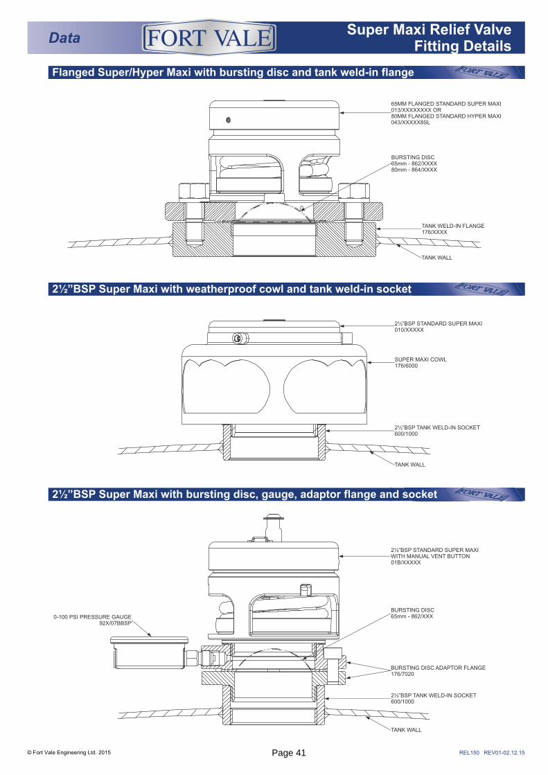
2½”BSP Super Maxi with bursting disc, gauge, adaptor flange and socket
Flanged Super/Hyper Maxi with bursting disc and tank weld-in flange
2½”BSP Super Maxi with weatherproof cowl and tank weld-in socket
© Fort Vale Engineering Ltd. 2015
DataSuper Maxi Relief Valve
Fitting Details
®
2½”BSP STANDARD SUPER MAXI010/XXXXX
SUPER MAXI COWL176/6000
TANK WALL
2½”BSP TANK WELD-IN SOCKET600/1000
2½”BSP STANDARD SUPER MAXIWITH MANUAL VENT BUTTON01B/XXXXX
0-100 PSI PRESSURE GAUGE92X/07BBSP
TANK WALL
BURSTING DISC65mm - 862/XXX
BURSTING DISC ADAPTOR FLANGE176/7020
2½”BSP TANK WELD-IN SOCKET600/1000
65MM FLANGED STANDARD SUPER MAXI013/XXXXXXXX OR80MM FLANGED STANDARD HYPER MAXI043/XXXXX8SL
TANK WALL
BURSTING DISC65mm - 862/XXXX80mm - 864/XXXX
TANK WELD-IN FLANGE176/XXXX
Page 41
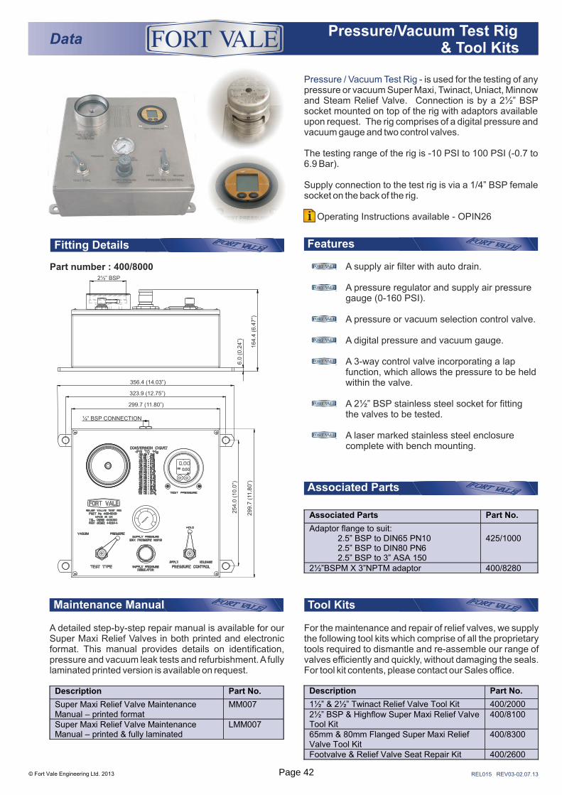
A supply air filter with auto drain.
A pressure regulator and supply air pressure gauge (0-160 PSI).
A pressure or vacuum selection control valve.
A digital pressure and vacuum gauge.
A 3-way control valve incorporating a lap function, which allows the pressure to be held within the valve.
A 2½” BSP stainless steel socket for fitting the valves to be tested.
A laser marked stainless steel enclosure complete with bench mounting.
FeaturesFitting Details
Part number : 400/8000
DataPressure/Vacuum Test Rig
& Tool Kits
®
Associated Parts Part No.
Adaptor flange to suit: 2.5” BSP to DIN65 PN10 2.5” BSP to DIN80 PN6 2.5” BSP to 3” ASA 150
425/1000
2½”BSPM X 3”NPTM adaptor 400/8280
Associated Parts
REL015 REV03-02.07.13
Maintenance Manual
A detailed step-by-step repair manual is available for our Super Maxi Relief Valves in both printed and electronic format. This manual provides details on identification, pressure and vacuum leak tests and refurbishment. A fully laminated printed version is available on request.
Description Part No.
1½” & 2½” Twinact Relief Valve Tool Kit 400/2000 2½” BSP & Highflow Super Maxi Relief Valve Tool Kit
400/8100
65mm & 80mm Flanged Super Maxi Relief Valve Tool Kit
400/8300
Footvalve & Relief Valve Seat Repair Kit 400/2600
Tool Kits
For the maintenance and repair of relief valves, we supply the following tool kits which comprise of all the proprietary tools required to dismantle and re-assemble our range of valves efficiently and quickly, without damaging the seals. For tool kit contents, please contact our Sales office.
© Fort Vale Engineering Ltd. 2013
Pressure / Vacuum Test Rig - is used for the testing of any pressure or vacuum Super Maxi, Twinact, Uniact, Minnow and Steam Relief Valve. Connection is by a 2½” BSP socket mounted on top of the rig with adaptors available upon request. The rig comprises of a digital pressure and vacuum gauge and two control valves.
The testing range of the rig is -10 PSI to 100 PSI (-0.7 to 6.9 Bar).
Supply connection to the test rig is via a 1/4” BSP female socket on the back of the rig.
Operating Instructions available - OPIN26i
Description Part No.
Super Maxi Relief Valve Maintenance Manual – printed format
MM007
Super Maxi Relief Valve Maintenance Manual – printed & fully laminated
LMM007
0
2
46
8
10
11
¼” BSP CONNECTION
299.7 (11.80”)
323.9 (12.75”)
254.0
(10.0
”)
299.7
(11
.80”)
356.4 (14.03”)
2½” BSP
6.0
(0.2
4”)
164.4
(6.4
7”)
Page 42

THIS PAGE IS INTENTIONALLY BLANKPage 43
Fort Vale UKHead Office & Manufacturing PlantTel : +44 (0)1282 687120Fax : +44 (0)1282 687110Email : [email protected]
Fort Vale USATel : +1 281 471 8100Fax : +1 281 471 8116Email : [email protected]
Fort Vale NetherlandsTel : +31 (0)180 483333Fax : +31 (0)180 410797Email : [email protected]
Fort Vale Russian FederationTel : +7 916 682 0947Email : [email protected]
Fort Vale P.R. ChinaTel : +86 21 6442 1367Fax : +86 21 6442 1376Email : [email protected]
Fort Vale SingaporeTel : +65 6515 9950Fax : +65 6515 3034Email : [email protected]
Fort Vale AustraliaTel : +61 7 3310 4854Email : [email protected]
www.fortvale.com
All goods supplied will be subject to Fort Vale Engineering Ltd Terms and Conditions of Sale (Ref. FV4) which are available upon request, or may be viewed at www.fortvale.com.
Please note that this brochure and the contents herein remain the property of Fort Vale Engineering Limited.
This brochure may not be copied or reproduced, or the information contained herein divulged to any third party without the prior written permission of Fort Vale Engineering Limited.
Repair/refurbishment/resetting of Fort Vale valves may be carried out only by trained and authorised personnel. Fort Vale Engineering Limited shall not, in any circumstances, be liable for injuries, losses, expenses or damage, direct or consequential, sustained by the buyer or any person which may in any degree be attributable to the adoption, either by the buyer or any third party, of technical or other information, data or advice given on behalf of Fort Vale Engineering Limited or however otherwise caused in relation to the use of its products in accordance with Fort Vale Engineering Limited’s recommendation.
The specifications included in this catalogue are intended to be generic and must be interpreted as equivalent or functionally equivalent. The identification of many items is facilitated by illustrations (photographs and line drawings). The mention of, or reference to specific companies, national standards, or trade names, including those that might appear on the photographs, is intended for illustration purposes only. It does not imply an endorsement, preference or availability of any specific standard, brand or supplier.
The data and information contained herein is being provided for information only and without responsibility, and Fort Vale Engineering Limited makes no representations or warranties, either expressed or implied, as to the accuracy, completeness, or fitness for a particular purpose. Fort Vale Engineering Limited does not accept any responsibility or liability with regard to the reliance on, or use of this data and information.
REV10_19.03.18
®
© Fort Vale Engineering Ltd. 2018