summer 16 examinations subject code: 17556 model answer … · 2018-11-03 · capstan lathe turret...
TRANSCRIPT

MAHARASHTRA STATE BOARD OF TECHNICAL EDUCATION (Autonomous)
(ISO/IEC - 27001 - 2005 Certified)
_____________________________________________________________________________________________
Page 1 of 26
SUMMER – 16 EXAMINATIONS Subject Code: 17556 Model Answer Page No: ____/ N Important Instructions to examiners: 1) The answers should be examined by key words and not as word-to-word as given in the model answer scheme. 2) The model answer and the answer written by candidate may vary but the examiner may try to assess the understanding level of the candidate. 3) The language errors such as grammatical, spelling errors should not be given more importance. (Not applicable for subject English and Communication Skills) 4) While assessing figures, examiner may give credit for principal components indicated in the figure. The figures drawn by candidate and model answer may vary. The examiner may give credit for any equivalent figure drawn. 5) Credits may be given step wise for numerical problems. In some cases, the assumed constant values may vary and there may be some difference in the candidate’s answers and model answer. 6) In case of some questions credit may be given by judgment on part of examiner of relevant answer based on candidate’s understanding. 7) For programming language papers, credit may be given to any other program based on equivalent concept.

MAHARASHTRA STATE BOARD OF TECHNICAL EDUCATION (Autonomous)
(ISO/IEC - 27001 - 2005 Certified)
_____________________________________________________________________________________________
Page 2 of 26
Q. NO.
MODEL ANSWER
MARKS
TOTAL MARKS
1 Attempt any Five 5 x 4 20
a)
Sr.No.
Parameters Traditional Machining Process
Non-traditional Machining Process
1 Tool geometry
It uses a cutting tool of fixed geometry
It uses some sort of energy along with a tool which doesn't have a fixed geornetry
2 Cutting ability
Hard metals are difficult to cut and sometimes impossible
Almost any known hard material can be cut.
3 Metal removal method
Metal is removed in the form of chips
Metal is removed by melting, vapourization, electrochemical reaction etc.
4 Tool force Higher tool forces are required to cut harder material
Tool force is independent of the material hardness.
4m (1m per
point)
4m
b)
• Water from the reservoir is pumped to the intensifier using a hydraulic pump. • The intensifier accepts the water at low pressure and pressurizes it to around 400 MPa. • Pressurized water is then sent to the accumulator. The accumulator temporarily stores the pressurized water during the idle period and given out during cutting. • Pressurized water then enters the nozzle by"passlnq through the control valve and flow regulator.
2m for
diag
2m for exp
4m

MAHARASHTRA STATE BOARD OF TECHNICAL EDUCATION (Autonomous)
(ISO/IEC - 27001 - 2005 Certified)
_____________________________________________________________________________________________
Page 3 of 26
• Control valve controls the direction of water and limits the pressure of water under permissible urrnts.. • Flow regulator regulates and controls the flow rate of water. • Pressurized water finally enters the nozzle. Here, it expands with a tremendous increase in its kinetic energy. High velocity water jet is produced by the nozzle. • The jet stream coming out of the nozzle strikes the workpiece and induces stresses. These stresses are used to cuts the workpiece. • The water is then collected in a drain system
c) Adaptive control machining, there is improvement in the production rate and reduction in the machining cost as a result of calculating andsetting of optimal parameters during machining
The principal reason for using CNCmachines is because it reduces non-productive time in machining operation.
It reduces the tool set-up time, tool change time, work piece handling time and other delays
The in-process time is reduced by using optimum speeds and/or
feeds.
It increases the tool life simultaneously with time saving, the adaptive control system contribute to lower operating costs, which justifies the extra price of adding AC to a conventional NC machine
It increase the production rates,Increased tool life,greater part protection, Less operator intervention,Easier part programming.
4m (1m per
function)
4m
d) Sr.No
Capstan lathe Turret lathe
1 It is light duty machine Turret lathes are relatively more robust and heavy dutv machine.
2 The turret head is mounted on the ram and the ram is mounted on the saddle and moves on the guideways
The turret head is directly mounted on the saddle and the saddle slides over the bed ways
3 The saddle will not be moved during machining
The saddle is moved along with the turret head during machining.
4 The lengthwise movement of turret is less
The lengthwise movement of turret is more.
5 Only short workpieces can be machined
Long work pieces can be machined.
6 Collet is used to hold the workpiece
Jaw chuck is used to hold the workpiece.
7 It is easy to move the turret head as it slides over the ram.
It is difficult to move the turret head along with saddle.
8 The turret head cannot be moved crosswise
The turret head can be moved crosswise in some turret lathes.
4m (1m per
point)
4m

MAHARASHTRA STATE BOARD OF TECHNICAL EDUCATION (Autonomous)
(ISO/IEC - 27001 - 2005 Certified)
_____________________________________________________________________________________________
Page 4 of 26
9 As the construction of lathe is not rigid heavy cut cannot be clven
As the construction of lathe is rigid, heavy cut can be qiven.
10 It is used for machining work pieces upto 60 mm diameter
It is used for machining workpieces up to 200 mm diameter
11 Capstan lathes generally deal with short or long rod type blanks held in collet.
Turret lathes mostly work on chucking type jobs held in the quick actinq chucks.
12 The turret travels with limited stroke length within a saddle type guide block, called auxiliary bed, which is clamped on the main bed
In turret lathe, the heavy turret being mounted on the saddle which directly slides with larger stroke length on the main bed
13 External screw threads are cut in capstan lathe using a self opening die being mounted in one face of the turret
In turret lathes external threads are cut by a single point or multipoint chasing tool being mounted on the front slide and moved by a short leadscrew and a swing type half nut.
14 The turret of capstan lathe is called as a capstan head which may be circular or hexagonal
The turret of turret lathe is called as a turret head which may be square, octagonal or hexagonal.
e) COMPARISON BETWEEN DRESSING AND TRUEING
Dressing Trueing
1.It is the process of cleaning and opening the face of the wheel
l. It is the process making the periphery concentric to bore dia.
2. It removes loading defect 2. It removes glazing defect
3. It is done with a start wheel dresser
3. It is done with a diamond tool.
4. Profiles cannot be obtained 4. Profiles can be obtained on the wheel face
5. It is done to recover proper cutting action of the wheel
5. It is done to recover the lost shape of the face
4m (1m per
point)
4m
f)
4m 4m

MAHARASHTRA STATE BOARD OF TECHNICAL EDUCATION (Autonomous)
(ISO/IEC - 27001 - 2005 Certified)
_____________________________________________________________________________________________
Page 5 of 26
g) OBJECTIVES OF MACHINE TOOL MAINTENANCE (i) To minimize the number of breakdown. (ii) To keep plant in good working condition at the lowest possible cost. (iii) To minimize the hindrance and interruption of work. (iv) To carry out the work of all the machines smoothly. (v) Minimizing the loss of production becauseof equipment failure. (vi) Prolongingthe life of capital assets by minimizing the rate of wear and tear. (vii) To minimize accidents through regular inspection and repair of safety devices. (viii) To improve the quality of products and to improve productivity TYPES OF MAINTENANCE The following are the types of maintenance: (i) Preventive maintenance. (ii) Predictive maintenance. (lii) Breakdown maintenance. (iv) Corrective maintenance. (v) Scheduled maintenance.
2m for
bojectives
2m for
types
4m
2 Attempt any four 4 x 4 16
a) The controlling parameters in WEDM are: (i) Discharge current. (ii) Pulse duration. (iii) Pulse frequency. (iv) Wire speed (v) Wire tension. (vi) Dielectric flow Advantages of WEDM (i) Straight holes can be produced to close tolerances. (ii) As a NC unit is used, the machine can be operated unattended for longer period of time. . (iii) High degree of accuracy and good surface finishlcan be obtained. (iv) Very sharp angles can be cut with almost no radius. (v) EDM eliminates the need for post-rnachininq heat treating and possible part distortion. . (vi) The parts produced are burr-free Disadvantages of WEDM (i)Wire cannot be reused, because due to sparking the wire no longer remains round. (ii) If proper tension in wire is not maintained, the surface finish will be poor. (iii) Only electrically conductive material can be machined. (iv) Residual stresses are induced in the work piece during machining. (v) The maximum depth of work piece which can be machined is around 90 mm. (vi) A hole is necessary in the work piece for machining of surface which are
2m for
listing
1m for adv
(1/2 m each
point)
1m for
disadv(1/2 m each
point)
4m
MAHARASHTRA STATE BOARD OF TECHNICAL EDUCATION (Autonomous)
(ISO/IEC - 27001 - 2005 Certified)
_____________________________________________________________________________________________
Page 6 of 26
not at the edges.
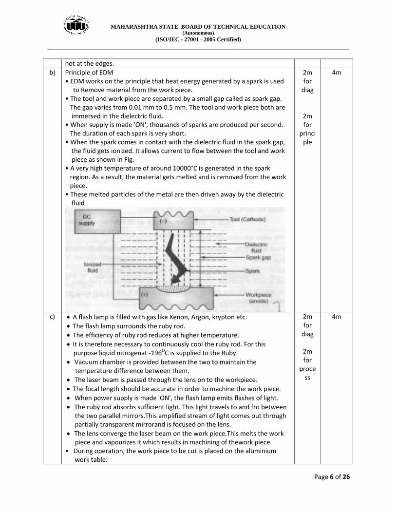
b) Principle of EDM • EDM works on the principle that heat energy generated by a spark is used to Remove material from the work piece. • The tool and work piece are separated by a small gap called as spark gap. The gap varies from 0.01 mm to 0.5 mm. The tool and work piece both are immersed in the dielectric fluid. • When supply is made 'ON', thousands of sparks are produced per second. The duration of each spark is very short. • When the spark comes in contact with the dielectric fluid in the spark gap, the fluid gets ionized. It allows current to flow between the tool and work piece as shown in Fig. • A very high temperature of around 10000°C is generated in the spark region. As a result, the material gets melted and is removed from the work piece. • These melted particles of the metal are then driven away by the dielectric fluid
2m for
diag
2m for
principle
4m
c) A flash lamp is filled with gas like Xenon, Argon, krypton etc.
The flash lamp surrounds the ruby rod.
The efficiency of ruby rod reduces at higher temperature.
It is therefore necessary to continuously cool the ruby rod. For this purpose liquid nitrogenat -196OC is supplied to the Ruby.
Vacuum chamber is provided between the two to maintain the temperature difference between them.
The laser beam is passed through the lens on to the workpiece.
The focal length should be accurate in order to machine the work piece.
When power supply is made 'ON', the flash lamp emits flashes of light.
The ruby rod absorbs sufficient light. This light travels to and fro between the two parallel mirrors.This amplified stream of light comes out through partially transparent mirrorand is focused on the lens.
The lens converge the laser beam on the work piece.This melts the work piece and vapourizes it which results in machining of thework piece.
• During operation, the work piece to be cut is placed on the aluminium work table.
2m for
diag
2m for
process
4m

MAHARASHTRA STATE BOARD OF TECHNICAL EDUCATION (Autonomous)
(ISO/IEC - 27001 - 2005 Certified)
_____________________________________________________________________________________________
Page 7 of 26
• The motion can be given either to work piece or to the beam or both depending upon the requirement. • The Operator visually inspects the process and accordingly adjusts the motion
d) The axes on machining centers are divided into two types. (i) Linear axes: X, Y and Z axes are identified as linear axes (ii) Rotary axes: A, Band C axes are identified as rotary axes Z-axis: • First the Z-axis is fixed for the machine tool. It is the main spindle axis. • In a vertical milling machine, the vertical axis of the machine spindle is set as the Z axis • The positive Z-axis is taken in the direction that causes the cutting tool to move away from the workpiece. (i.e. it increases the distance between the workpiece and the tool. • It means that movement of the cutter in upward direction is positive Z-axis. The movement of the tool in downward direction i.e. towards the workpiece is set as negative Z-axis. X-axis: • It is always horizontal and parallel to the workpiecejholding surface. • It indicates the longitudinal travel of the work table.
Y-axis: • It is perpendicular to both X and Z-axes. •It is also horizontal and indicates the cross travel of the table
2m for
diag
2m for
process
4m

MAHARASHTRA STATE BOARD OF TECHNICAL EDUCATION (Autonomous)
(ISO/IEC - 27001 - 2005 Certified)
_____________________________________________________________________________________________
Page 8 of 26
A-axis: • It is the axis of-rotary motion of a tool along -axis. • Clockwise rotation is considered as positive movement looking in +X direction. B-axis: • It is the axis of rotary motion of a tool along Y-axis. • Clockwise rotation is considered as positive movement looking in +Y direction. C-axis: • It is the axis of rotary motion of a tool along Z-axis. • Clockwise rotation considered as positive movement looking in +Z direction.
e) The canned cycle may be defined as a set of instructions stored in the
memory of the system, to perform a fixed sequence of operations. it reduces the length of program.Canned cycle is used for repetitively and common used machining operations. And it is stored in the memory under the G codes. It is also called as fixed cycle. Canned cycles should be canceled after their use by using the code G-80.
1m for
canned
cycles
4m

MAHARASHTRA STATE BOARD OF TECHNICAL EDUCATION (Autonomous)
(ISO/IEC - 27001 - 2005 Certified)
_____________________________________________________________________________________________
Page 9 of 26
Sr.No.
Subroutine Canned cycle
1 It is the separate program which is called in the main program
It is not a program but part of the main program
2 It is called and ended by miscellaneous function
It is called and ended by preparatory function
3 It is used when multiple passes are locations.
It is used when multiple passes are required at the same location
4 One point is given in every block of instruction till the operation is completed
Directly the final point is given in the block of instruction.
5 The cutter path for every point is to be given by the programmer
The cutter path for every pass is generated by the controlter
3m for
difference
f) CLASSlFICATION OF BROACHING MACHINES A Broaching machine is classified as below: According to the method of operation:
(a) Pull broach (b) Push broach (c) Stationary broach
According to the kind of operation: (a) Internal broach (b) External broach
According to their use (a) Single purpose (b) Combination
According to their construction: (a) Solid (b) Built up (c) Progressive (d) Inserted tooth
According to their function: (a) Keyway broach (b) Spline broach (c) Sizing broach (d) Spiral broach (e) surface broach
The advantages of broaching are : 1. The process can be done for both internal and external machining. 2. It is simple operation, hence does not require highly skilled operator. 3. As loading and unloading is rapid, the rate of production is high. 4. As both roughing and finishing can be done in one pass, so broaching is fast operation. 5. Broaching is faster than any other machining process. 6. High accuracy and higher surface finish can be obtained.
2m for
classify
1m for adv
(1/2 m each
point)
1m for
disadv(1/2 m each
point)
4m

MAHARASHTRA STATE BOARD OF TECHNICAL EDUCATION (Autonomous)
(ISO/IEC - 27001 - 2005 Certified)
_____________________________________________________________________________________________
Page 10 of 26
7. The cutting force of the broach serves to clamp the work piece and hold it firmly in position. 8. Any form that can be produced on a broaching tool can be produced by the tool. The disadvantages of broaching are as follows: 1. It is a single purpose tool. 2. Tool cost is very high, so the process is justified only for mass production. 3. In some cases, it is not suited for low production rates 4. The parts to be broached must be strong enough to withstand high cutting forces. 5. Surface to be broached must be accessible. 6. Blind holes cannot be easily produced. 7. Tool sharpening is difficult.and expensive process.
3 Attempt any four 4 x 4 16
a) (i)G 04 - Tool length compensatlon in positive (+) direction. (ii) G 21 - Rectangular pocket milling cycle (CW). (iii) M03 -Spindle Start (Clockwise) (iv) M98 -Call Subroutine
4m (1m per
code)
4m
b) COMPARISON BETWEEN PULL AND PUSH BROACH
Sr. NO.
Pull Broach Push Broach
1 This broach is pulled out of the work piece
This broach is pushed through the work piece
2 It is longer in length than push broach
It is comparatively shorter in length
3 It is used where a longer surface is to be broached
It is used where a short length is to be broached
4 It carries more number of teeth It carries less number of teeth
5 The pull broach is in tension The push broach is in compression
4m ( 1m per
point)
4m
c)
4m 4m
d) Types of boring heads are as follows:
Simple Boring Head
Trailing Cut Boring Head
2m for
types
4m

MAHARASHTRA STATE BOARD OF TECHNICAL EDUCATION (Autonomous)
(ISO/IEC - 27001 - 2005 Certified)
_____________________________________________________________________________________________
Page 11 of 26
Simple Boring Head • The fig. bellow shows a simple boring head. It consists of a circular body. Two or three slots are made radially in the body in which cutters are fitted. A micrometer dial is provided for the precision adjustment of the tool if required. • Boring head can be keyed at any desired position on the boring bar it supports the tool. A boring head may have number of cutters. • The advantage of having several cutters is metal removal rate is high, hence machining time is reduced. Boring heads are always provided with two sets of cutters. One set is being used for roughing and other for finishing
OR Trailing Cut Boring Head • It consists of a body which is clamped to the boring bar with the clamping
screw C.
The boring head can slide in the slot along the length of the boring bar and clamped in the desired position.
The body carries arrangement for mounting of two boring tools. The tools are held firmly in position by means of sets screws.
The tool can be fed into the work piece by the adjusting screw A.
2m for
exp of any one

MAHARASHTRA STATE BOARD OF TECHNICAL EDUCATION (Autonomous)
(ISO/IEC - 27001 - 2005 Certified)
_____________________________________________________________________________________________
Page 12 of 26
e) Comparison between Up Milling And Down Milling
Sr.NO
UP Milling Down Milling
1 In conventional milling the cutter rotates in a direction opposite to that in which the work is fed
In climb milling, the cutter rotates inthe same direction to which the work is fed
2 The chip thickness progresses gradually from start to cut to end ofcut (i.e. chip thickness is minimumat the beginning of cut and maximum at end of the cut).
The chip thickness is maximum at the beginning of cut and minimum at end of the cut
3 The cutting force tends to lift the w/p away from the fixture
The cutting force tends to seat thew/p into the fixture.
4 It is difficult to pour coolant at the point of machining
It is easy to pour coolant at the point of machining
5 It is difficult to design the fixture Fixture designer is easy
6 Wavy type of surface finish is obtained
Better surface finish is obtained
7 The cutter does not start cutting metal as soon as it comes in contact with the workpiece
The cutter starts cutting metal as soon as it contacts the w/p.
8 The cutting force is Downward at beginning and reaches to upward at the end of the cut.
The cutting force is upward at beginning ofcut and reaches to downwardat the end of the cut
4m (1m per
point)
4m
f) The dividing head is of three types: 1.Plain or Simple dividing head. 2.Universal dividing head. 3.Optical dividing head.
1m for
listing
4m

MAHARASHTRA STATE BOARD OF TECHNICAL EDUCATION (Autonomous)
(ISO/IEC - 27001 - 2005 Certified)
_____________________________________________________________________________________________
Page 13 of 26
83 divisions are indexed by differential indexing method.
For indexing the index crank will have to be moved by 20 holes in 43 hole circle.
3m for
indexing
4 Attempt any four 4 x 4 16
a)
1253 N110 G90 G21 G94 EOB N120 M06 T01 EOB N130 M03 S800 EOB N140 G00 X-10 Y-10 EOB N150 G00 Z5 M08 EOB N160 G01 Z-3 F90 EOB N170 G01 X-3 Y-3 EOB N180 G01 Y28 EOB
4m 4m

MAHARASHTRA STATE BOARD OF TECHNICAL EDUCATION (Autonomous)
(ISO/IEC - 27001 - 2005 Certified)
_____________________________________________________________________________________________
Page 14 of 26
N190 G01 X 12 Y 43 EOB N200 G01 X53 EOB N210 G01 Y12 EOB N220 G01 X33 EOB N230 G01 Y-3 EOB N240 G01 X-10 EOB N250 G00 Z5 EOB N260 G28 EOB N270 M05 EOB N280 M09 EOB N290 M30 EOB
b) SPECIFICATION OF THE JIG BORING MACHINE A jig boring machine should be specified by the following details:
(a) Distance from spindle axis from column. (b) Maximum diameter of hole drilled. (c) Maximum diameter of hole bored. (d) Maximum weight of work piece permissible. (e) Number of spindles speeds. (f) Maximum table travel (longitudinal). (g) Maximum table travel (cross). (h) Maximum vertical travel of spindle. (i) Taper in spindle hole.
4m (1m per
point)
4m
c) column and knee type milling machine is shown in Fig. Any column and knee type milling consist of : Base:It is a heavy cast iron casing at the bottom of the machine. It carries a column at its one end. It also serves as reservoir for the coolant. Column: A vertical column mounted on base carriers accurately machined guideways on its front face. A spindle is mounted on the front face of column.Guideways are machined on its front face. Knee: knee is mounted on the front umn and can slide in vertical direction on
the sideways. The knee can be operated by the elevting screw provided below the knee. Machined guideways are provided on the top surface of the knee.
Saddle: It is mounted on the knee and can move over it in cross-direction. Accuraye machined guideways are provided on -top of saddle. Table:The table is mounted on saddle and can be moved in longitudinal direction. The table is provided with T-slots to hold the workpiece. Also the cutting fluid can be drained back to the reservoir through these slots.
2m for
diag
2m for
const.
4m

MAHARASHTRA STATE BOARD OF TECHNICAL EDUCATION (Autonomous)
(ISO/IEC - 27001 - 2005 Certified)
_____________________________________________________________________________________________
Page 15 of 26
d) T· Slot Milling
• The size of the T-slots depends upon the size of the T-slot bolts which will be used. Dimensions of T-slots and T-slot bolts are standardized for specific bolt diameters.
• Two milling cutters are required for milling T-slots, a T-slot milling cutter and either a side milling cutter or an end milling cutter.
• The side milling cutter or the end milling cutter is first used to cut a slot in the work piece equal in width to the throat width of the T-slot.
• Position the T-slot milling cutter over the edge of the work piece and align it with the previously cut groove.
• The T-slot milling cutter is then used to cut the head space to the prescribed dimensions. • Feedthe table longitudinally to make the cut. Use good amount of cutting
oil between the cutter and operation.
2m for
diag
2m for exp
4m
MAHARASHTRA STATE BOARD OF TECHNICAL EDUCATION (Autonomous)
(ISO/IEC - 27001 - 2005 Certified)
_____________________________________________________________________________________________
Page 16 of 26
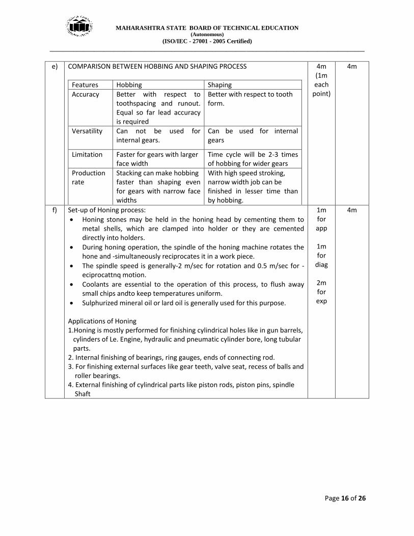
e) COMPARISON BETWEEN HOBBING AND SHAPING PROCESS
Features Hobbing Shaping
Accuracy Better with respect to toothspacing and runout. Equal so far lead accuracy is required
Better with respect to tooth form.
Versatility Can not be used for internal gears.
Can be used for internal gears
Limitation Faster for gears with larger face width
Time cycle will be 2-3 times of hobbing for wider gears
Production rate
Stacking can make hobbing faster than shaping even for gears with narrow face widths
With high speed stroking, narrow width job can be finished in lesser time than by hobbing.
4m (1m each
point)
4m
f) Set-up of Honing process:
Honing stones may be held in the honing head by cementing them to metal shells, which are clamped into holder or they are cemented directly into holders.
During honing operation, the spindle of the honing machine rotates the hone and -simultaneously reciprocates it in a work piece.
The spindle speed is generally-2 m/sec for rotation and 0.5 m/sec for -eciprocattnq motion.
Coolants are essential to the operation of this process, to flush away small chips andto keep temperatures uniform.
Sulphurized mineral oil or lard oil is generally used for this purpose. Applications of Honing 1.Honing is mostly performed for finishing cylindrical holes like in gun barrels, cylinders of Le. Engine, hydraulic and pneumatic cylinder bore, long tubular parts. 2. Internal finishing of bearings, ring gauges, ends of connecting rod. 3. For finishing external surfaces like gear teeth, valve seat, recess of balls and roller bearings. 4. External finishing of cylindrical parts like piston rods, piston pins, spindle Shaft
1m for app
1m for
diag
2m for exp
4m

MAHARASHTRA STATE BOARD OF TECHNICAL EDUCATION (Autonomous)
(ISO/IEC - 27001 - 2005 Certified)
_____________________________________________________________________________________________
Page 17 of 26
5 Attempt any four 4x 4 16
a) Set-up of PAM: • The set-up of the process consists of:
(i) Plasma cutting torch. (ii) Tool and workpiece. (iii) Gas supply unit. (iv) Cooling system. (v) Power supply.
(i) Plasma cutting torch:
A plasma cutting torch is shown in Fig. It carries a tungsten electrode
fitted in a small chamber.
At other end of the torch is a small converging orifice called as nozzle.
One side of the torch provides a passage for supply of gas into the torch. (ii) Tool and workpiece:
The electrode is connected to negative terminal of a D.e. power supply and therefore acts as a cathode.
The nozzle is made anode by connecting to the positive terminal of the
power supply through a suitable resistor. This resistor limits the current
through the nozzle to about 50 A.
The workpiece to be machined is also connected to the positive terminal of the supply.
The anode and cathode are separated by an insulator.
1m for app
(1/2 m per
point)
2m for set
up
1m for
diag
4m

MAHARASHTRA STATE BOARD OF TECHNICAL EDUCATION (Autonomous)
(ISO/IEC - 27001 - 2005 Certified)
_____________________________________________________________________________________________
Page 18 of 26
(iii) Gas supply unit:
It consists of gas cylinder, regulators and gas supply hoses.
The commonly used gases are argon or nitrogen or the mixture of two. For certain useful purposes, a percentage of hydrogen may be added.
The choice of the gas depends upon the material to be cut, economics and the quality of the cut edge desired.
The flow rate of the gas varies directly with the thickness of the workpiece. (iv) Coolingsystem: o A provision is made for circulating the water around the torch so that the electrodes and the nozzle both remains water cooled (v) Powersupply:
When supply is made ON, a strong arc is struck between the electrode and the nozzle and the gas is forced into the chamber.
When the gas molecules collide with the high velocity electrons of the arc, plasma is formed. This plasma is forced through the nozzle (anode) onto the workpiece.
The heat produced from this jet of plasma is sufficient to raise the workpiece temperature above its melting point and the high velocity gas stream effectively blows the molten metal away
Applications of PAM (i) For stack cutting, plate beveling, shape cutting and piercing. (ii) In manufacture of automotive and rail road components. (iii) It can cut hot extrusions to desired length
MAHARASHTRA STATE BOARD OF TECHNICAL EDUCATION (Autonomous)
(ISO/IEC - 27001 - 2005 Certified)
_____________________________________________________________________________________________
Page 19 of 26
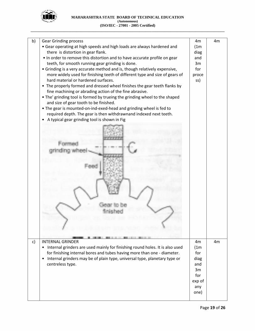
b) Gear Grinding process • Gear operating at high speeds and high loads are always hardened and
there is distortion in gear flank. • In order to remove this distortion and to have accurate profile on gear
teeth, for smooth running gear grinding is done. • Grinding is a very accurate method and is, though relatively expensive,
more widely used for finishing teeth of different type and size of gears of hard material or hardened surfaces.
• The properly formed and dressed wheel finishes the gear teeth flanks by fine machining or abrading action of the fine abrasive.
• The' grinding tool is formed by trueing the grinding wheel to the shaped and size of gear tooth to be finished.
• The gear is mounted-on-ind-exed-head and grinding wheel is fed to required depth. The gear is then withdrawnand indexed next teeth.
• A typical gear grinding tool is shown in Fig
4m (1m diag and 3m for
process)
4m
c) INTERNAL GRINDER • Internal grinders are used mainly for finishing round holes. It is also used
for finishing internal bores and tubes having more than one - diameter. • Internal grinders may be of plain type, universal type, planetary type or
centreless type.
4m (1m for
diag and 3m for
exp of any one)
4m

MAHARASHTRA STATE BOARD OF TECHNICAL EDUCATION (Autonomous)
(ISO/IEC - 27001 - 2005 Certified)
_____________________________________________________________________________________________
Page 20 of 26
Planetory Internal Grinder
• The working principle of planetary internal grinder is shown in Fig. In planetary grinder a work is held stationary and mounted on table of machine. • The grinding wheel has three motions (a) It rotates about its axis. (b) ath around the axis of the hole in the work piece. (c) It travels Ion itudinall inside the work piece. • The longitudinal travel can be obtained by (a) Reciprocating movements of the grinding wheel or, (b) By moving the slide along with the work piece. • The grinding wheel is given a radial infeed (into the work piece) after each planetary circle is completed. This gives the depth of cut. • It is possible to grin lar e holes of var in diameter depending upon how
much the wheel spindle is made to run eccentric. • This machine is used only for bore grinding of heavy or irregular shape
work, which is difficult to rotate. OR Centre-less Internal Grinder
• In centre-less grinding the workpiece is supported between the three rolls.
The rolls are pressure roll, supporting roll and a regulating roll (grinding wheel.
• All the three rolls rotates in the same direction and rotates the workpiece with them.
• The workarece and grinding wheel rotates in the same direction. • The direction of rotation of the three rolls and workpiece is opposite.

MAHARASHTRA STATE BOARD OF TECHNICAL EDUCATION (Autonomous)
(ISO/IEC - 27001 - 2005 Certified)
_____________________________________________________________________________________________
Page 21 of 26
• The grinding wheel always contacts the workpiece at the horizontal centerline of the regulating wheel.
• This ensures uniform wall thickness of the workpiece and also ensures concentricity of the bore with the external surface of the workpiece. • To load or unload the workpiece, the pressure roll can be swung away. • The grinding wheel is given infeed so as to obtain the required depth of cut. • This type of machine is used for work having repetitive nature. • It has advantages similar to external centre-less grinding.
d) A wheel marked as 51A30L8V21 will have following specifications: 51 -Manufacturer's symbol. A -Abrasive type (Aluminium oxide. ) 30 -Grain size (Medium.) L -Grade (Soft.) 8 -Structure (Dense.) V -Type of Bond (Vitrified.) 21 -Manufacturer's marking
4m 4m
e) REPAIR CYCLE ANALYSIS
Preven ive maintenance involves carrying out inspection, repair and complete overhaul of the machine.
The inspection and 'repatr activities are carried out on the machine tool in a particular sequene
This sequence is determined forehand in the early life of the machine.
Thus the cycle of I, R (small or medium repair) and C (complete overhaul) is repeated till three or four overhauling.
The cycle of inspection, small repair: and rnedlurn repair between two complete overhauls is called as repair cycle.
OR The cycle from machine commissioning to first complete overhaul is called as repalr cycle.
For example, (i) I1- S1 - S2 - I3- M1- I4- S3 - I5- S4 - I6- M2- I7-S5 – I8 - S6 - I9- C is a repair cycle for a particular grinding machine. After every inspections, small repair is carried out. However, after every three inspections, medium repair is carried out and after two medium repairs, complete overhauling is carried out. (ii) C - I1- I2- S1 - I4- I5- I6- M1- I7- I8 - I9- S2 - I10- I11- I12- C is a repair cycle for an elevator which consists of one ,medium repair, two small repairs and twelve inspections between two overhauls
4m (1m for
example and 3m for
exp.)
4m
f) The maintenance record used during preventive maintenance of any machine will have a format similar to what is shown in Fig
4m 4m

MAHARASHTRA STATE BOARD OF TECHNICAL EDUCATION (Autonomous)
(ISO/IEC - 27001 - 2005 Certified)
_____________________________________________________________________________________________
Page 22 of 26
6 Attempt any four 4 x 4 16
a) Process Characteristics of AJM are Abrasives
The abrasive material used is Al2O3 or SiC.
The grain size is around 25 IJm.
The shape of abrasive is generally spherical.
The mass Flow rate is 3-20 g/min, 2. Gas carrier
The type of gas used js Air, N2 or CO2
The air density is 1.3 kg/m3, Velocity 150-300 m/s and pressure 2-8 bar.
The flow rate is around 30 L/min. 3. Nozzle
The nozzle is made of Tungsten carbide or sapphire.
Its shape is circular, 0.3-0.5 mm internal diameter or rectangular (0.08mm,0.5mm to 6.61 mm,0.51 mm).
The tip distance is 0.25-15 mm.
The life of WC is 12-30 hour and sapphire is 300 hours.
The operating angle is 60° to 90° to the surface.
Stand-off distance - 0.5 to 5 mm. Applications of A.JM
(i) Fine drilling and microwelding. (ii) Machining of-semi conductors. (iii) Frosting and abrading of glass articles. (iv) Machining of intricate profile on hard and fragile materials.
4m(3m for
characteristic and 1m for any two app)
4m
MAHARASHTRA STATE BOARD OF TECHNICAL EDUCATION (Autonomous)
(ISO/IEC - 27001 - 2005 Certified)
_____________________________________________________________________________________________
Page 23 of 26
(v) Cleaning and cutting operations on materiel like germanium, silicon, quartz,mica (vi) Machining of brittle materialslike glass,ceramics,refractories etc
b) An Automatic tool changer or ATC is used in computerized numerical control (CNC) machine tools to improve the production and tool carrying
capacity of the machine.
ATC changes the tool very quickly, reducing the non-productive time. It is used to improve the capacity of the machine to work with a numbers of tools.It is also used to change worn out or broken tools.
After getting the tool change command, the tool to be changed will come to a fixed position known as the "tool change position".
The ATC arm will come to this position and will pick up the tool.
The arm swivels between machine turret and magazine. It will have two grippers on the two sides. Each gripper can rotate through 90°, to deliver tools to the front face of the turret.
One will pick up the old tool from turret and the other will pick up the new tool from magazine. It will then rotate to 180 ° and will place the tools at their due position.
The use of automatic changers increases the productive time and reduces the unproductive time to a large extent.
It provides the storage of the tools which are returned automatically to the machine tool after carrying out the required operations, increases the flexibility of the machine tool, makes it easier to change heavy and large tools, and permits the automatic renewal of cutting edges.
4m 4m
c) Classification Of Milling Cutter • The milling cutter are generally classified as follows: 1. Plainmilling cutter
(a) Light duty plain milling cutter (b) Heavy duty plain milling cutter- (c) Helical plain milling cutter
2. Side milling cutter , (a) Plain side milling cutter (b) Half side milling cutter (c) Staggered teeth side milling cutter (d) Interlocking teeth side milling cutter
3. End milling cutter (a) Solid end milling cutter (b) Shell end milling cutter
4. Metal slitting milling cutter (a) Plain metal slitting cutter (b) Staggered teeth metal slitting cutter
5. Angle milling cutter (a) Single angle milling cutter (b) Double angle milling cutter
6. Formed milling cutter (a) Convex form milling cutter (b) Concave form milling cutter
4m 4m
MAHARASHTRA STATE BOARD OF TECHNICAL EDUCATION (Autonomous)
(ISO/IEC - 27001 - 2005 Certified)
_____________________________________________________________________________________________
Page 24 of 26
(c) Corner rounding form milling cutter (d) Formed gear cutter
7. Slot milling cutter (a) T-slot milling cutter (b) Dovetail slot milling cutter
8. Thread milling cutter 9. Fly milling cutter
d) Working of Burnishing Process
In this process fine surface finish is produced by the planetary rotation of hardened rollers over a bored or turned metal surface.
All the machined surfaces consist of a series 01 peaks and valleys (surface irregularities) of irregular height and spacing.
The plastic deformation created by burnishing is a displacement of the material from the peaks which cold flows under pressure into the valleys.
There is rubbing and peening action on work surface by smooth but hard tool, spreading minute surface irregularities into flat surface.
This helps to flatten the high spots by allowing plastic flow of the metal.
The edges of the metal can be smoothened by pushing it through a die that will smooth out the burrs and the blanked edge caused by the die break.
Advantages of Burnishing Process • Internal and external surfaces can be burnished. • Improves surface hardness and fatigue strength. • Long Tool Life, No Operator Skill Required, Low Torque & Power Requirements. • It also eliminates the Lapping and Honing processes. • Producesmirror finish in One Passwith accurate sizing and close tolerances. • No Additional Machine Investment is required as the tool can be attached to any Standard Machine Tool available in the Shop • Assembly problems are totally eliminated since part dimensions are maintained within tolerances.
4m (1m for adv and 3m for
working)
4m
e) Basic maintenance practices for shaft and pulley: For Shaft and pulleys •Shaft misalignment is responsible for up to 50% of breakdowns in rotating machinery. Those breakdown cause increased machine downtime, which translates directly into higher costs. Additionally, incorrect alignment places a greater load on machine components, resulting in increased wear and tear. •As in the case of shaft alignment, belt alignment or pulley alignment is an important maintenance task. When carried out correctly, it can prevent break,downs and save considerable costs. Belt alignment and pulley alignment are synonymous, as the process of belt alignment hinges on the correct alignment of the pulleys on which the belt runs. For the sake of clarity, however, we will speak of belt alignment.
4m (2m for
shaft and 2m for
gear)
4m

MAHARASHTRA STATE BOARD OF TECHNICAL EDUCATION (Autonomous)
(ISO/IEC - 27001 - 2005 Certified)
_____________________________________________________________________________________________
Page 25 of 26
•Belt alignment concerns aligning the belts in a manner that results in the less wear on the belts and lowest energy loss for the machine or drive run practice this means that the grooves of the pulleys are in line with one another •A shaft drive system will have multiple bearings supporting the shafts. I bearings are worn out, it will accelerate the wear of the rest of the system. times, replacing the bearings in a shaft drive system will require special tools.Consult the service manual for the model in question to have special holders,locknut wrenches, bearing pullers and drivers ready for the job at hand. • Lubrication is the most basic maintenance item for shaft drive systems. The final drive unit requires periodic oil changes. When draining the oil, check for signs of metal shavings as this could be a sign of damage to the gears. • The maximum center to center distance of pulleys should be around 15 times that of the pitch of the smallest pulley and should not exceed 20 times the pitch of this pulley. Greater distances than this require tight control of belt tension becausea small amount of sketch will cause a large drop in belt tension, creating slippage and reducing power transmission efficiency Following practice should be followed for gears:
Check all bolting and retighten if necessary.
Check oil level while unit is not running.
Remove inspection cover and examine gear teeth for undue wear.
With unit running, observe shaft extensions for axial or radial runout.
Inspect unit for oil leaks.
Check for any noise while in operation.
Check operating temperature.
Check oil viscosity.
High oil temperatures are not harmful to the metal of the gears, bearings,
and houslnqs, but could be hazardous to the life of oil seals as well as to the
oil itself)
f) Sr.No. Predictive Maintenance Preventive Maintenance
1 Predictive Maintenance is carried out as the machines are running in their normal production modes (when failure is detected)
Preventive Maintenance tasks are completed when the machines are shut down (during weekly-off).
2 It is done when any part of the machine tool require maintenance.
It is done at the preset schedule
3 It is requirement based It is time based
4m (1m per
point)
4m

MAHARASHTRA STATE BOARD OF TECHNICAL EDUCATION (Autonomous)
(ISO/IEC - 27001 - 2005 Certified)
_____________________________________________________________________________________________
Page 26 of 26
4 Concern is given to the actual condition and performance capability of the machine.
Actual condition and performance capability of the machine has no concern
5 Predictive Maintenance jobs are less repetitive in nature
Preventive Maintenance jobs are more repetitive in nature
6 It is more suitable for heavy, costly and very critical equipments where overhauling requires excessive downtime
It is more suitable for industries where large number of similar or nearly similar machines are available
7 For example, turbines, wind mill, furnaces of steel mill.
For example, machine tools of machine shop, pumps, compressor, motors etc.
8 The predictive maintenance is done on the basis of condition monitoring
The preventive maintenance is doneon the basis of manufacturer'srecommendation, past experienceand judgement