submersible p f oilfield ... - quality esp...
TRANSCRIPT
ELECTRIC
SUBMERSIBLE PUMPS
FOR OILFIELD APPLICATIONs PRODUCT CATALOGUE
CANADIAN OILWELL SYSTEMS COMPANY LTD. COSCO Pump Company Limited
COSCO ESP, Inc.
Head Office 9760 – 60 Avenue Edmonton, Alberta, Canada T6E 0C5 Phone: + 1 780 430-0840 Fax: + 1 780 430-0367 E-mail: [email protected] www.coscoesp.com
September, 2010
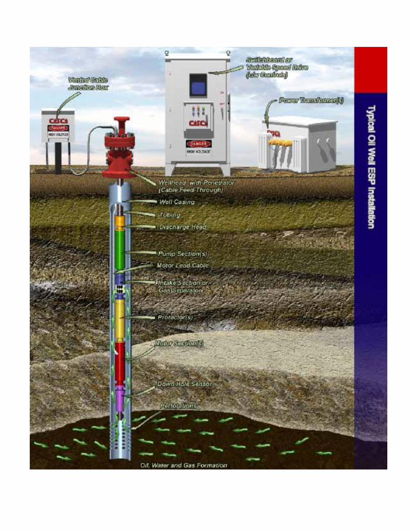
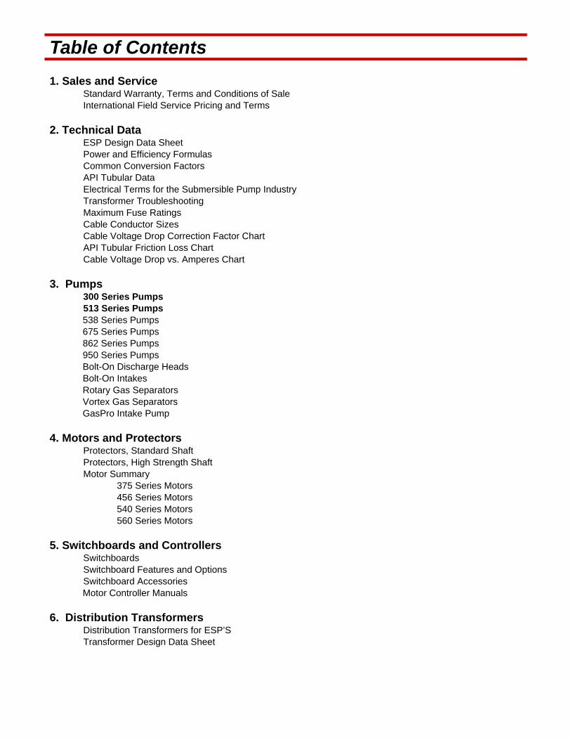
Table of Contents 1. Sales and Service
Standard Warranty, Terms and Conditions of Sale International Field Service Pricing and Terms
2. Technical Data ESP Design Data Sheet Power and Efficiency Formulas Common Conversion Factors API Tubular Data Electrical Terms for the Submersible Pump Industry Transformer Troubleshooting Maximum Fuse Ratings Cable Conductor Sizes Cable Voltage Drop Correction Factor Chart API Tubular Friction Loss Chart Cable Voltage Drop vs. Amperes Chart
3. Pumps 300 Series Pumps 513 Series Pumps 538 Series Pumps 675 Series Pumps 862 Series Pumps 950 Series Pumps Bolt-On Discharge Heads Bolt-On Intakes Rotary Gas Separators Vortex Gas Separators GasPro Intake Pump
4. Motors and Protectors Protectors, Standard Shaft Protectors, High Strength Shaft Motor Summary
375 Series Motors 456 Series Motors 540 Series Motors 560 Series Motors
5. Switchboards and Controllers Switchboards Switchboard Features and Options Switchboard Accessories Motor Controller Manuals
6. Distribution Transformers Distribution Transformers for ESP’S
Transformer Design Data Sheet

Table of Contents (continued.) 7. Wellheads and Connectors
Electrical Connector Systems Two-Piece 900 Top Entry Connector Systems Three-Piece 900 Top Entry Connector Systems COSCO Universal Tubing Head Adapters COSCO Type SA Universal Tubing Head Adapters COSCO Type FA Universal Tubing Head Adapters COSCO Type A Universal Tubing Head Adapters COSCO SAPA Packoff Tubing Head Adapter
8. Cable Power Cable Specifications – Type A,B,C,D Cable Accessories
Flat Cable Extensions
9. Accessories Check Valves and Bleeders By-Pass Tools (Y-Tool) Automatic Diverter Valves Blanking Plugs for Bypass Tools Down Hole Sensors Cable Protectors
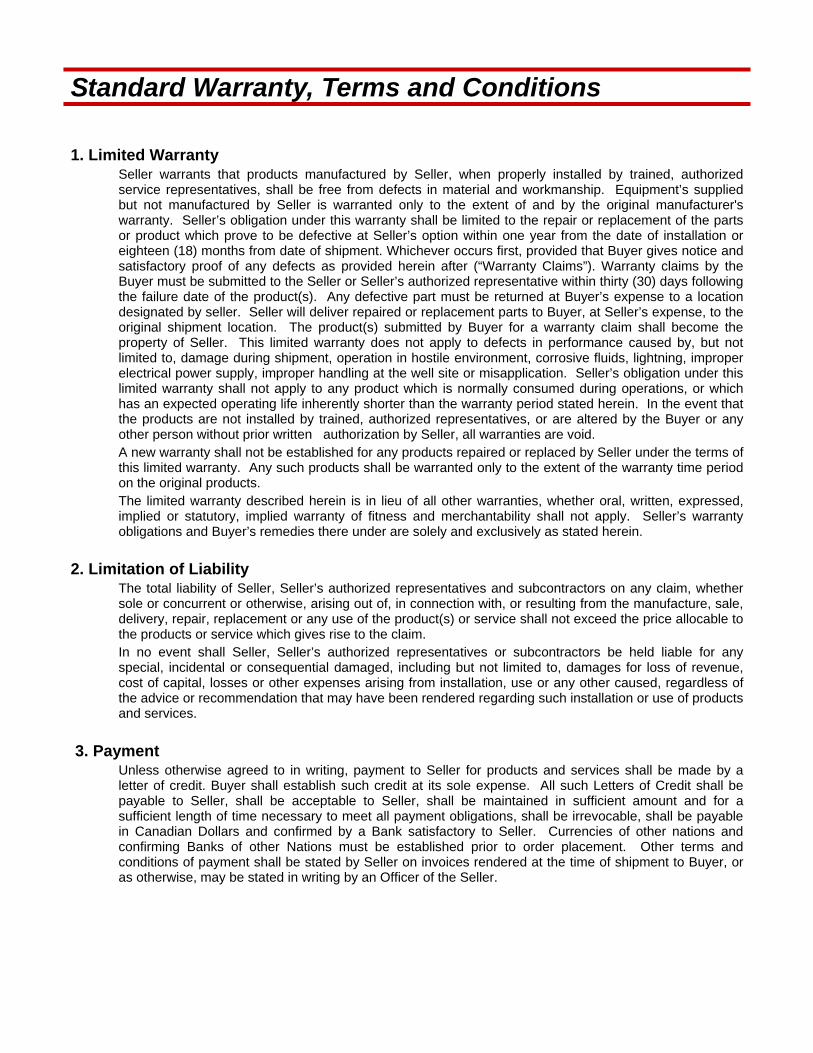
Standard Warranty, Terms and Conditions 1. Limited Warranty
Seller warrants that products manufactured by Seller, when properly installed by trained, authorized service representatives, shall be free from defects in material and workmanship. Equipment’s supplied but not manufactured by Seller is warranted only to the extent of and by the original manufacturer's warranty. Seller’s obligation under this warranty shall be limited to the repair or replacement of the parts or product which prove to be defective at Seller’s option within one year from the date of installation or eighteen (18) months from date of shipment. Whichever occurs first, provided that Buyer gives notice and satisfactory proof of any defects as provided herein after (“Warranty Claims”). Warranty claims by the Buyer must be submitted to the Seller or Seller’s authorized representative within thirty (30) days following the failure date of the product(s). Any defective part must be returned at Buyer’s expense to a location designated by seller. Seller will deliver repaired or replacement parts to Buyer, at Seller’s expense, to the original shipment location. The product(s) submitted by Buyer for a warranty claim shall become the property of Seller. This limited warranty does not apply to defects in performance caused by, but not limited to, damage during shipment, operation in hostile environment, corrosive fluids, lightning, improper electrical power supply, improper handling at the well site or misapplication. Seller’s obligation under this limited warranty shall not apply to any product which is normally consumed during operations, or which has an expected operating life inherently shorter than the warranty period stated herein. In the event that the products are not installed by trained, authorized representatives, or are altered by the Buyer or any other person without prior written authorization by Seller, all warranties are void. A new warranty shall not be established for any products repaired or replaced by Seller under the terms of this limited warranty. Any such products shall be warranted only to the extent of the warranty time period on the original products. The limited warranty described herein is in lieu of all other warranties, whether oral, written, expressed, implied or statutory, implied warranty of fitness and merchantability shall not apply. Seller’s warranty obligations and Buyer’s remedies there under are solely and exclusively as stated herein.
2. Limitation of Liability The total liability of Seller, Seller’s authorized representatives and subcontractors on any claim, whether sole or concurrent or otherwise, arising out of, in connection with, or resulting from the manufacture, sale, delivery, repair, replacement or any use of the product(s) or service shall not exceed the price allocable to the products or service which gives rise to the claim. In no event shall Seller, Seller’s authorized representatives or subcontractors be held liable for any special, incidental or consequential damaged, including but not limited to, damages for loss of revenue, cost of capital, losses or other expenses arising from installation, use or any other caused, regardless of the advice or recommendation that may have been rendered regarding such installation or use of products and services.
3. Payment Unless otherwise agreed to in writing, payment to Seller for products and services shall be made by a letter of credit. Buyer shall establish such credit at its sole expense. All such Letters of Credit shall be payable to Seller, shall be acceptable to Seller, shall be maintained in sufficient amount and for a sufficient length of time necessary to meet all payment obligations, shall be irrevocable, shall be payable in Canadian Dollars and confirmed by a Bank satisfactory to Seller. Currencies of other nations and confirming Banks of other Nations must be established prior to order placement. Other terms and conditions of payment shall be stated by Seller on invoices rendered at the time of shipment to Buyer, or as otherwise, may be stated in writing by an Officer of the Seller.
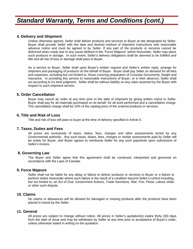
Standard Warranty, Terms and Conditions (cont.) 4. Delivery and Shipment
Unless otherwise agreed, Seller shall deliver products and services to Buyer at site designated by Seller. Buyer shall provide Seller with the date and desired method of shipment instructions with reasonable advance notice and must be agreed to by Seller. If any part of the products or services cannot be delivered when ready due to any cause defined in the “Force Majeure” article hereunder, Seller may place such products in storage. In such event, Seller’s delivery obligations shall be deemed to be fulfilled and title and all risk of loss or damage shall pass to Buyer.
As a service to Buyer, Seller shall upon Buyer's written request and Seller’s written reply, arrange for shipment and packaging of products on the behalf of Buyer. Buyer shall pay Seller on demand for all fees and expenses, including but not limited to, those covering preparation of Consular Documents, freight and insurance. In providing this service to reasonable instructions of Buyer, or in their absence, Seller shall act according to it’s best judgment. Seller shall be without liability on any claim asserted by the Buyer with respect to such shipment service.
5. Order Cancellation Buyer may cancel an order at any time prior to the date of shipment by giving written notice to Seller. Buyer shall pay for all materials purchased on its behalf, for all work performed and a cancellation charge. The cancellation charge shall be 10% of the catalog price of the ordered products or services.
6. Title and Risk of Loss Title and risk of loss will pass to buyer at the time of delivery specified in Article 4.
7. Taxes, Duties and Fees All prices are exclusively of taxes, duties, fees, charges and other assessments levied by any Governmental authority. Any such taxes, duties, fees, charges or similar assessments paid by Seller will be solely for Buyer, and Buyer agrees to reimburse Seller for any such payments upon submission of Seller’s invoice.
8. Governing Law The Buyer and Seller agree that this agreement shall be construed, interpreted and governed on accordance with the Laws of Canada.
9. Force Majeure Seller shall not be liable for any delay or failure to deliver products or services to Buyer or a failure to perform duties hereunder where such failure is the result of a condition beyond Seller’s control including, but not limited to, an Act of God, Government Actions, Trade Sanctions, War, Fire, Flood, Labour strike or other such dispute.
10. Claims No claims or allowances will be allowed for damaged or missing products after the products have been placed in transit by the Seller.
11. General All prices are subject to change without notice. All prices in Seller’s quotation(s) expire thirty (30) days from the date of issue and may be withdrawn by Seller at any time prior to acceptance of Buyer’s order, unless otherwise stated in writing on the quotation.
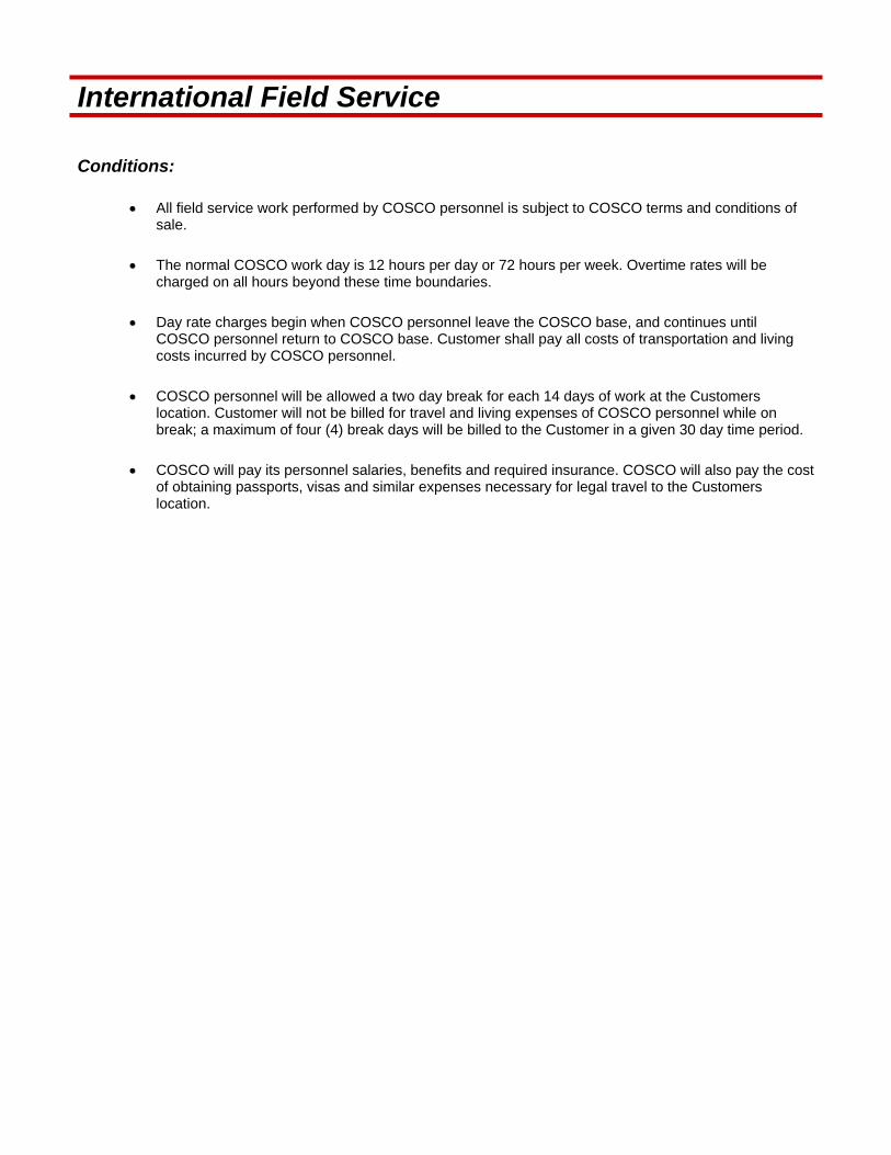
International Field Service
Conditions:
All field service work performed by COSCO personnel is subject to COSCO terms and conditions of sale.
The normal COSCO work day is 12 hours per day or 72 hours per week. Overtime rates will be charged on all hours beyond these time boundaries.
Day rate charges begin when COSCO personnel leave the COSCO base, and continues until COSCO personnel return to COSCO base. Customer shall pay all costs of transportation and living costs incurred by COSCO personnel.
COSCO personnel will be allowed a two day break for each 14 days of work at the Customers location. Customer will not be billed for travel and living expenses of COSCO personnel while on break; a maximum of four (4) break days will be billed to the Customer in a given 30 day time period.
COSCO will pay its personnel salaries, benefits and required insurance. COSCO will also pay the cost of obtaining passports, visas and similar expenses necessary for legal travel to the Customers location.
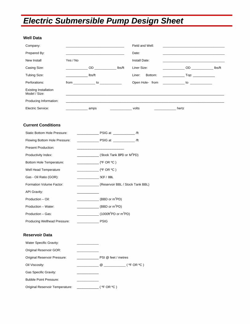
Electric Submersible Pump Design Sheet
Well Data
Company: ________________________________ Field and Well: __________________________________
Prepared By: ________________________________ Date: __________________________________
New Install Yes / No Install Date: __________________________________
Casing Size: ____________ OD ____________ lbs/ft Liner Size: ____________ OD ____________ lbs/ft
Tubing Size: ____________ lbs/ft Liner: Bottom: ____________ Top: ____________
Perforations: from ____________ to ____________ Open Hole- from ____________ to ____________
Existing Installation Model / Size: _______________________________________________________________________________________
Producing Information: _______________________________________________________________________________________
Electric Service: ____________ amps ____________ volts ____________ hertz
Current Conditions
Static Bottom Hole Pressure: ____________ PSIG at ____________ /ft
Flowing Bottom Hole Pressure: ____________ PSIG at ____________ /ft
Present Production: _____________________
Productivity Index: ____________ (Stock Tank BPD or M3PD)
Bottom Hole Temperature: ____________ (ºF OR ºC )
Well Head Temperature ____________ (ºF OR ºC )
Gas - Oil Ratio (GOR): ____________ SCF / BBL
Formation Volume Factor: ____________ (Reservoir BBL / Stock Tank BBL)
API Gravity: ____________
Production – Oil: ____________ (BBD or m3PD)
Production – Water: ____________ (BBD or m3PD)
Production – Gas: ____________ (1000ft3PD or m3PD)
Producing Wellhead Pressure: ____________ PSIG
Reservoir Data
Water Specific Gravity: ____________
Original Reservoir GOR: ____________
Original Reservoir Pressure: ____________ PSI @ feet / metres
Oil Viscosity: ____________ @ ____________ ( ºF OR ºC )
Gas Specific Gravity: ____________
Bubble Point Pressure: ____________
Original Reservoir Temperature: ____________ ( ºF OR ºC )

Electric Submersible Pump Design Sheet
PVT Data
Test Pressure (PSIA)
OIL FVF (RB/STB)
Gas FVF (RB/SMCF)
Oil Viscosity (CP/SSU)
Solution GOR (SCF/STB)
1
2
3
4
5
Other Problems
Sand Paraffin
Corrosion (Type & Cause) _________________________________ H2S
Injected Chemicals Scale
Other Problems ___________________________________________________________________________
Equipment Design Specifications
Desired Pump Setting Depth: ___________ m / ft. Measured Pump Setting Depth: ___________ m / ft.
Desired Producing Rate: ___________ bbl / day Producing Fluid Level: ___________ m / ft. Operating Pump Intake Pressure: ___________PSI
Wellhead Pressure: ___________PSI ( Tubing) ___________PSI (Casing) Free Gas at Pump Intake Pressure:
Casing Vent: Atmosphere Flowline None
Additional Comments _________________________________________________________________________________________ _________________________________________________________________________________________ _________________________________________________________________________________________ _________________________________________________________________________________________ _________________________________________________________________________________________ _________________________________________________________________________________________
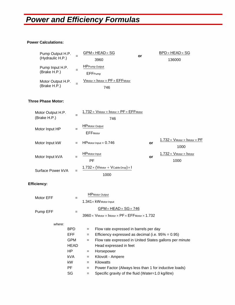
Power and Efficiency Formulas
Power Calculations:
Pump Output H.P. (Hydraulic H.P.)
= 3960
SGHEADGPM or
136000
SGHEADBPD
Pump Input H.P. (Brake H.P.)
= Pump
Output Pump
EFF
HP
Motor Output H.P. (Brake H.P.)
= 746
EFFPFIV MotorMotorMotor
Three Phase Motor:
Motor Output H.P. (Brake H.P.)
= 746
EFFPFIV1.732 MotorMotorMotor
Motor Input HP = Motor
Output Motor
EFF
HP
Motor Input kW = 0.746HP Input Motor or 1000
PFIV1.732 MotorMotor
Motor Input kVA = PF
HP Input Motor or
1000
IV1.732 MotorMotor
Surface Power kVA = 1000
I)V(V1.732 Drop CableMotor
Efficiency:
Motor EFF = Input Motor
Output Motor
kW1.341
HP
Pump EFF = 1.732EFFPFIV3960
746SGHEADGPM
MotorMotorMotor
where:
BPD = Flow rate expressed in barrels per day
EFF = Efficiency expressed as decimal (i.e. 95% = 0.95)
GPM = Flow rate expressed in United States gallons per minute
HEAD Head expressed in feet
HP = Horsepower
kVA = Kilovolt - Ampere
kW = Kilowatts
PF = Power Factor (Always less than 1 for inductive loads)
SG = Specific gravity of the fluid (Water=1.0 kg/litre)
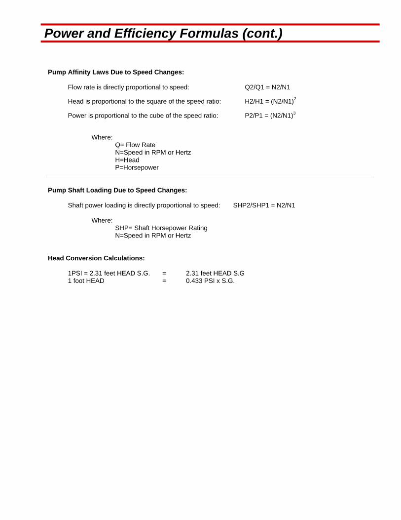
Power and Efficiency Formulas (cont.)
Pump Affinity Laws Due to Speed Changes:
Flow rate is directly proportional to speed: Q2/Q1 = N2/N1
Head is proportional to the square of the speed ratio: H2/H1 = (N2/N1)2
Power is proportional to the cube of the speed ratio: P2/P1 = (N2/N1)3
Where: Q= Flow Rate N=Speed in RPM or Hertz H=Head P=Horsepower
Pump Shaft Loading Due to Speed Changes:
Shaft power loading is directly proportional to speed: SHP2/SHP1 = N2/N1
Where: SHP= Shaft Horsepower Rating N=Speed in RPM or Hertz
Head Conversion Calculations:
1PSI = 2.31 feet HEAD S.G. = 2.31 feet HEAD S.G 1 foot HEAD = 0.433 PSI x S.G.
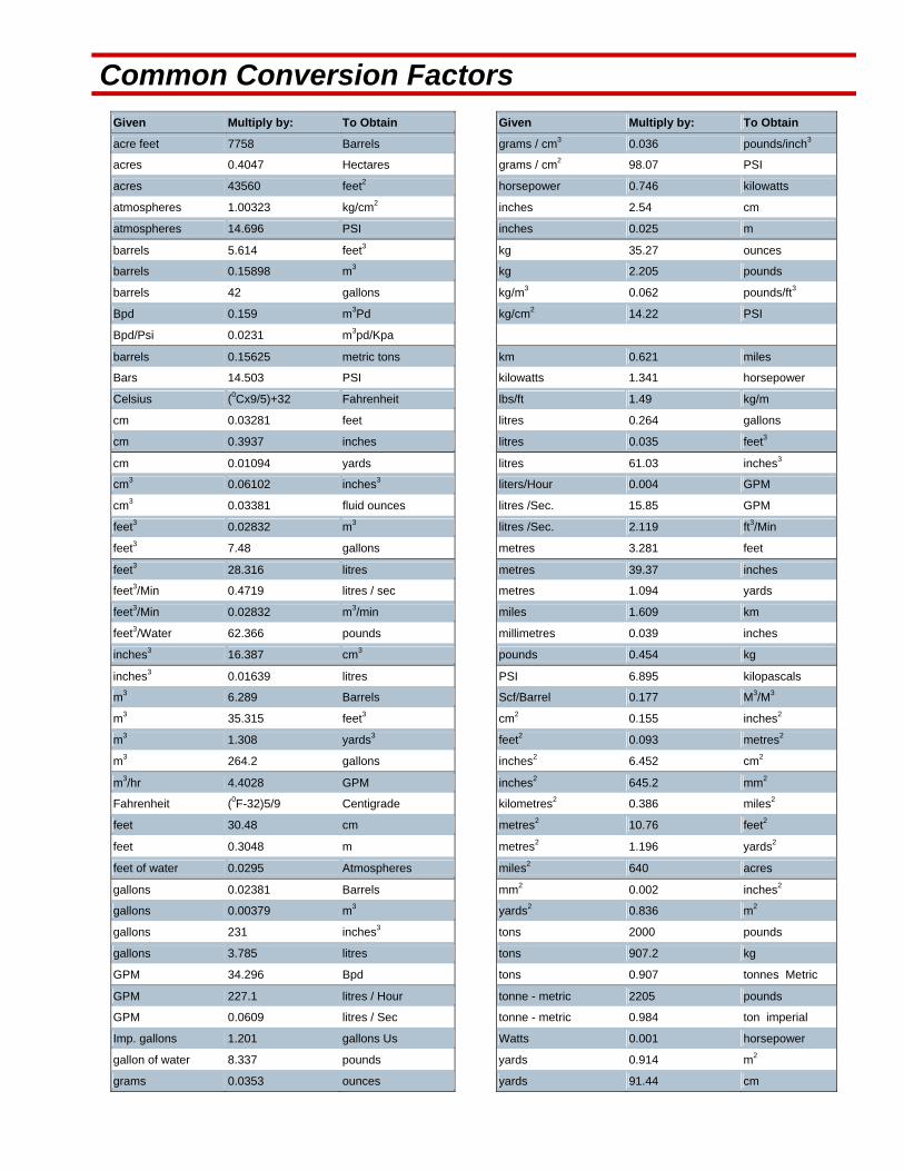
Common Conversion Factors
Given Multiply by: To Obtain Given Multiply by: To Obtain
acre feet 7758 Barrels grams / cm3 0.036 pounds/inch3
acres 0.4047 Hectares grams / cm2 98.07 PSI
acres 43560 feet2 horsepower 0.746 kilowatts
atmospheres 1.00323 kg/cm2 inches 2.54 cm
atmospheres 14.696 PSI inches 0.025 m
barrels 5.614 feet3 kg 35.27 ounces
barrels 0.15898 m3 kg 2.205 pounds
barrels 42 gallons kg/m3 0.062 pounds/ft3
Bpd 0.159 m3Pd kg/cm2 14.22 PSI
Bpd/Psi 0.0231 m3pd/Kpa
barrels 0.15625 metric tons km 0.621 miles
Bars 14.503 PSI kilowatts 1.341 horsepower
Celsius (0Cx9/5)+32 Fahrenheit lbs/ft 1.49 kg/m
cm 0.03281 feet litres 0.264 gallons
cm 0.3937 inches litres 0.035 feet3
cm 0.01094 yards litres 61.03 inches3
cm3 0.06102 inches3 liters/Hour 0.004 GPM
cm3 0.03381 fluid ounces litres /Sec. 15.85 GPM
feet3 0.02832 m3 litres /Sec. 2.119 ft3/Min
feet3 7.48 gallons metres 3.281 feet
feet3 28.316 litres metres 39.37 inches
feet3/Min 0.4719 litres / sec metres 1.094 yards
feet3/Min 0.02832 m3/min miles 1.609 km
feet3/Water 62.366 pounds millimetres 0.039 inches
inches3 16.387 cm3 pounds 0.454 kg
inches3 0.01639 litres PSI 6.895 kilopascals
m3 6.289 Barrels Scf/Barrel 0.177 M3/M3
m3 35.315 feet3 cm2 0.155 inches2
m3 1.308 yards3 feet2 0.093 metres2
m3 264.2 gallons inches2 6.452 cm2
m3/hr 4.4028 GPM inches2 645.2 mm2
Fahrenheit (0F-32)5/9 Centigrade kilometres2 0.386 miles2
feet 30.48 cm metres2 10.76 feet2
feet 0.3048 m metres2 1.196 yards2
feet of water 0.0295 Atmospheres miles2 640 acres
gallons 0.02381 Barrels mm2 0.002 inches2
gallons 0.00379 m3 yards2 0.836 m2
gallons 231 inches3 tons 2000 pounds
gallons 3.785 litres tons 907.2 kg
GPM 34.296 Bpd tons 0.907 tonnes Metric
GPM 227.1 litres / Hour tonne - metric 2205 pounds
GPM 0.0609 litres / Sec tonne - metric 0.984 ton imperial
Imp. gallons 1.201 gallons Us Watts 0.001 horsepower
gallon of water 8.337 pounds yards 0.914 m2
grams 0.0353 ounces yards 91.44 cm

API Tubular Data
API Regular Casing Size and OD (inches)
Thread Weight (lbs/ft)
OD (inches)
ID (inches)
Drift (inches)
Coupling OD(inches)
4 1/2 8 rd 9.5 4.500 4.090 3.965 5.000 10.5 4.500 4.052 3.927 5.000
11.6 4.500 4.000 3.875 5.000
5 1/2 8 rd 15.5 5.500 4.950 7.825 6.050 17.0 5.500 4.892 4.767 6.050
20.0 5.500 4.778 4.653 6.050
6 5/8 8 rd 17.0 6.625 5.136 6.010 7.390 24.0 6.625 5.921 5.796 7.390
7 8 rd 20.0 7.000 6.456 6.331 7.656 23.0 7.000 6.366 6.241 7.656
26.0 7.000 6.276 6.151 7.656
8 5/8 8 rd 28.0 8.625 8.017 7.892 9.625 36.0 8.625 7.825 7.700 9.625
9 5/8 8 rd 36.0 9.625 8.921 8.765 10.625 40.0 9.625 8.835 8.679 10.625
10 3/4 8 rd 40.5 10.750 10.050 9.894 11.750 55.5 10.750 9.760 9.604 11.750
13 3/8 8 rd 48.0 13.375 12.715 12.559 14.375 68.0 13.375 12.415 12.259 14.375
API Line Pipe Normal Size
1 1/4" 11 1/2rd 2.3 1.660 1.380 2.054 1 1/2" 11 1/2rd 2.8 1.900 1.610 2.200
2" 11 1/2rd 3.8 2.375 2.067 2.875
2 1/2" 8rd 7.7 3.500 3.068 4.000
3" 8rd 11.7 4.500 4.026 5.200
3 1/2" 8rd 19.5 6.625 6.065 7.390
4" 8rd 25.6 8.625 8.071 9.625
API Tubing (EUE)
1 1/2" 10rd 2.9 1.900 1.610 1.516 2.500 2" 8rd 4.7 2.375 1.995 1.901 3.063
2 1/2" 8rd 6.5 2.875 2.441 2.347 3.668
3" 8rd 9.3 3.500 2.992 2.867 4.500
3 1/2" 8rd 11.0 4.000 3.476 3.351 5.000
4" 8rd 12.8 4.500 3.958 3.833 5.563
API Tubing (EUE)
1 1/2" 10rd 2.8 1.900 1.610 1.516 2.200 2" 10rd 4.0 2.375 2.041 1.947 2.875
2 1/2" 10rd 6.4 2.875 2.441 2.347 3.500
3" 10rd 7.7 3.500 3.068 2.943 4.250
3 1/2" 8rd 9.5 4.000 3.548 3.423 4.750

Electrical Terms for the Submersible Pump Industry
Alternating Current (AC) - an electrical current that reverses its direction at recurring intervals Amp – abbreviation for ampere which is the measure of electrical flow Armored Cable (BX) - metal sheathed flexible cable or down hole 3 phase submersible cable Arrestor (surge) - stops or prevents a surge of electricity (such as from lightening) from harming down hole equipment Circuit – the pathway an electrical current travels to and from the main source Circuit Breaker – a device/switch which regulates the circuit’s amp capacity – if the predetermined amperage is exceeded, this opens the circuit (remember, the circuit is a closed ‘loop’) CODE – Implemented to ensure electrical safety measures. Canadian Electric Code (CEC), National Electric Code (NEC) Conductor – material through which electricity flows; for the most part wire; cable (3 conductor) Conduit – tube, pipe, or passageway that is used to house electrical wires Continuity – uninterrupted electrical path, the complete flow along a circuit (power source to fixture and back) CSA – Canadian Standards Association Current – electrical flow through conductors measured in Ampere’s Current Transformer (CT) - The current ratio of a CT is utilized to reduce the high motor current to an 0-5 Amp typical motor controller current measuring input Cycle – sequence of complete alternation (negative and positive) of a current
Direct Current (DC) - electrical current that flows in only one way Dielectric Tests – tests conducted at a much higher rate than rated nameplate voltage to assure insulation quality Disconnect – a device through which the conductors of a circuit are disconnected from their source Frequency – the number of complete cycles per unit of time for a periodic quantity such as alternating current Fuse – tube filled with combustible matter, metal band melts when circuit current exceeds its capacity Gauge – refers to the thickness of wire or the AWG (American Wire Gauge); also applies to bands and sheet metal. Ground – an electrical conductor connected to the ground/earth Harmonic – a sinusoidal component of an AC voltage that is a multiple of fundamental wave form frequency Hertz (Hz) – unit of frequency, one Hz equals one cycle per second Hot – ‘live’ wire that always carries a current (unless interrupted) as opposed to the neutral or ground Hi Pot – an electrical test where voltage is applied at a higher rate to assure insulated valve and that an electrical breakdown does not occur Junction Box (J–Box) – a box in which wires are joined together from the wellhead to the main power source (vents gas that might migrate from the down hole cable) Knockout – something found on an outlet box, switch–box, or J–box, which needs to be ‘knocked out’ to accommodate wires MegOHM – 1,000,000 OHMS Megger – an electrical test where voltage is applied to test insulative values of the equipment
Neutral – paired with hot wires returns the current back to origin to complete circuit OHM – unit of resistance Open Circuit – circuit with a physical interruption like a switch, disconnection, burnt fuse, etc. Raceway – electrical wires and/or cables in a specified space Receptacle – electrical plug Short Circuit – bad connection between wires Splice – making a connection or repair assuring electrical and mechanical properties to down hole submersible cable Stranded Wire – conductor wire made of several thinner strands of wire, twisted and braided together Switch – device used to continue, disrupt, or redirect a circuit Switchboard – a contained group of switches, relays, circuit breakers, etc. used to control distribution of power to other distribution equipment and larger loads Switch Gear – see switchboard Terminal – screw type: the wire is screwed to the device push–in type: a stripped wire can be pushed into the acceptor Transformer – a device that converts voltages Volt – electrical pressure unit Voltage – sufficient pressure to cause electrical current to flow Watt – a measure of electrical power VSD – Variable Speed Drive. A controller which allows you to vary the speed of the motor through modulations and applied frequency.
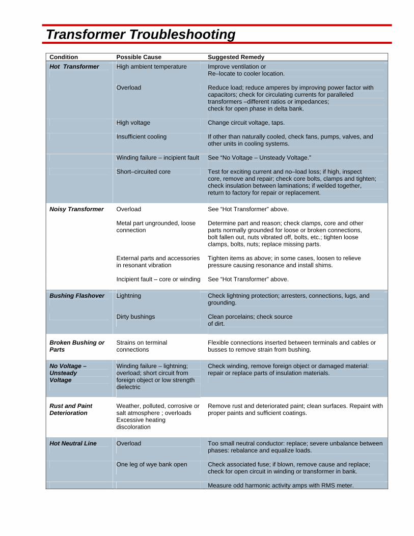
Transformer Troubleshooting
Condition Possible Cause Suggested Remedy
Hot Transformer
High ambient temperature Improve ventilation or Re–locate to cooler location.
Overload Reduce load; reduce amperes by improving power factor with capacitors; check for circulating currents for paralleled transformers –different ratios or impedances; check for open phase in delta bank.
High voltage Change circuit voltage, taps.
Insufficient cooling If other than naturally cooled, check fans, pumps, valves, and other units in cooling systems.
Winding failure – incipient fault See “No Voltage – Unsteady Voltage.”
Short–circuited core Test for exciting current and no–load loss; if high, inspect core, remove and repair; check core bolts, clamps and tighten; check insulation between laminations; if welded together, return to factory for repair or replacement.
Noisy Transformer
Overload See “Hot Transformer” above.
Metal part ungrounded, loose connection
Determine part and reason; check clamps, core and other parts normally grounded for loose or broken connections, bolt fallen out, nuts vibrated off, bolts, etc.; tighten loose clamps, bolts, nuts; replace missing parts.
External parts and accessories in resonant vibration
Tighten items as above; in some cases, loosen to relieve pressure causing resonance and install shims.
Incipient fault – core or winding
See “Hot Transformer” above.
Bushing Flashover
Lightning Check lightning protection; arresters, connections, lugs, and grounding.
Dirty bushings
Clean porcelains; check source of dirt.
Broken Bushing or Parts
Strains on terminal connections
Flexible connections inserted between terminals and cables or busses to remove strain from bushing.
No Voltage – Unsteady Voltage
Winding failure – lightning; overload; short circuit from foreign object or low strength dielectric
Check winding, remove foreign object or damaged material: repair or replace parts of insulation materials.
Rust and Paint Deterioration
Weather, polluted, corrosive or salt atmosphere ; overloads Excessive heating discoloration
Remove rust and deteriorated paint; clean surfaces. Repaint with proper paints and sufficient coatings.
Hot Neutral Line
Overload
Too small neutral conductor: replace; severe unbalance between phases: rebalance and equalize loads.
One leg of wye bank open
Check associated fuse; if blown, remove cause and replace; check for open circuit in winding or transformer in bank.
Measure odd harmonic activity amps with RMS meter.

Maximum Fuse Ratings Maximum Fuse Ratings with a Step Down Transformer Application:
Motor Type Time Delay “D”
Max Fuse Rating Non–Time Delay Max Fuse Rating
Max Setting Time Limit Type Circuit
Breaker
(Percent of Full–Load Current)
AC Single–Phase
Squirrel–Cage and Synchronous: 175 300 250
Full Voltage, Resistor and Reactor Starting
175 300 250
Auto–Transformer Starting <30A
175 250 200
Auto–Transformer Starting >30A 175 200 200
Wound Rotor 150 150 150
Direct Current 150 150 150
Maximum Fuse Ratings as a Percentage with a Step Up Transformer Application:
Over–current protection for power and distribution transformers rated 750 V or less, other than dry type transformers shall be protected by an individual over–current device on the primary side, rated or set at not more than 150% of the rated primary current(surface amperage requirement).
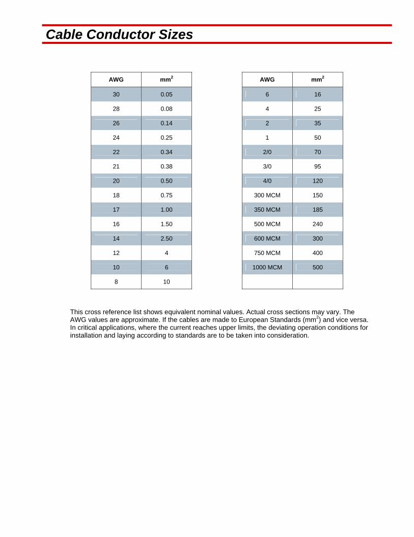
Cable Conductor Sizes
AWG mm2 AWG mm2
30 0.05 6 16
28 0.08 4 25
26 0.14 2 35
24 0.25 1 50
22 0.34 2/0 70
21 0.38 3/0 95
20 0.50 4/0 120
18 0.75 300 MCM 150
17 1.00 350 MCM 185
16 1.50 500 MCM 240
14 2.50 600 MCM 300
12 4 750 MCM 400
10 6 1000 MCM 500
8 10
This cross reference list shows equivalent nominal values. Actual cross sections may vary. The AWG values are approximate. If the cables are made to European Standards (mm2) and vice versa. In critical applications, where the current reaches upper limits, the deviating operation conditions for installation and laying according to standards are to be taken into consideration.
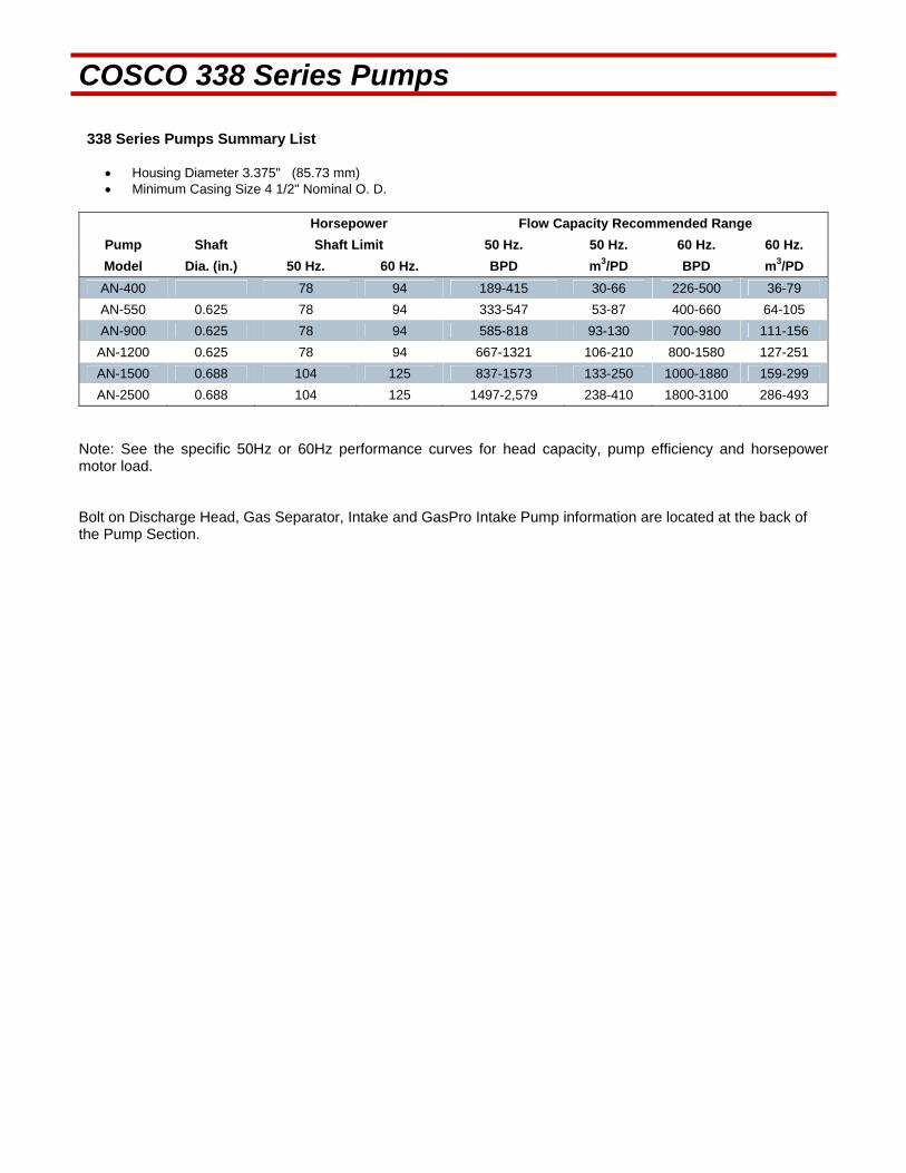
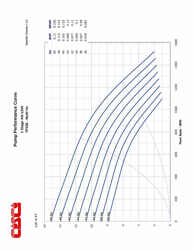
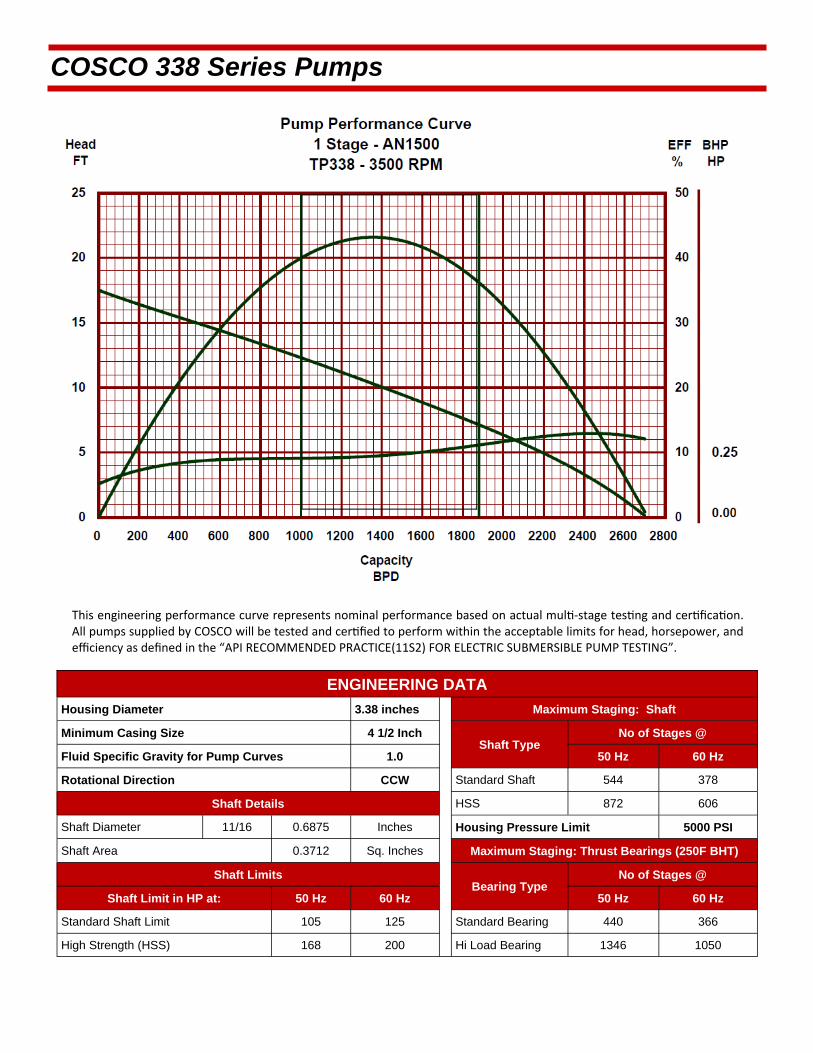
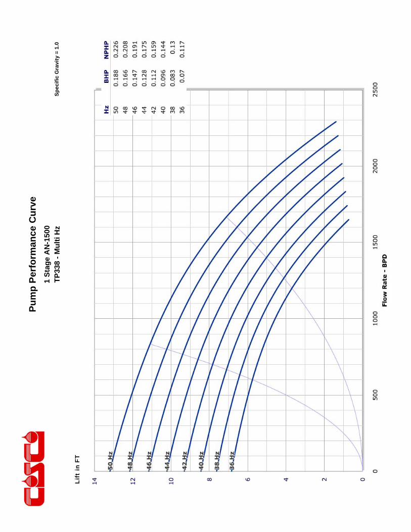
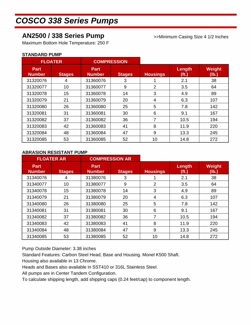
COSCO 338 Series Pumps 338 Series Pumps Summary List
Housing Diameter 3.375" (85.73 mm) Minimum Casing Size 4 1/2" Nominal O. D.
Horsepower Flow Capacity Recommended Range
Pump Shaft Shaft Limit 50 Hz. 50 Hz. 60 Hz. 60 Hz.
Model Dia. (in.) 50 Hz. 60 Hz. BPD m3/PD BPD m3/PD
AN-400 78 94 189-415 30-66 226-500 36-79
AN-550 0.625 78 94 333-547 53-87 400-660 64-105
AN-900 0.625 78 94 585-818 93-130 700-980 111-156
AN-1200 0.625 78 94 667-1321 106-210 800-1580 127-251
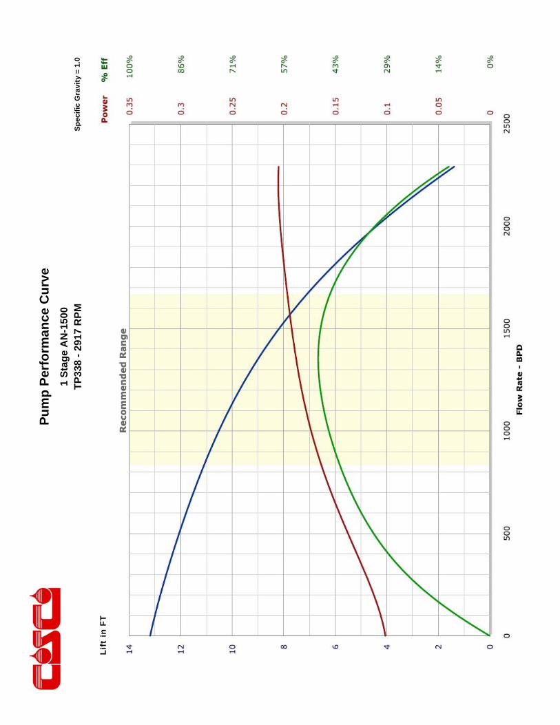
AN-1500 0.688 104 125 837-1573 133-250 1000-1880 159-299
AN-2500 0.688 104 125 1497-2,579 238-410 1800-3100 286-493
Note: See the specific 50Hz or 60Hz performance curves for head capacity, pump efficiency and horsepower motor load. Bolt on Discharge Head, Gas Separator, Intake and GasPro Intake Pump information are located at the back of the Pump Section.

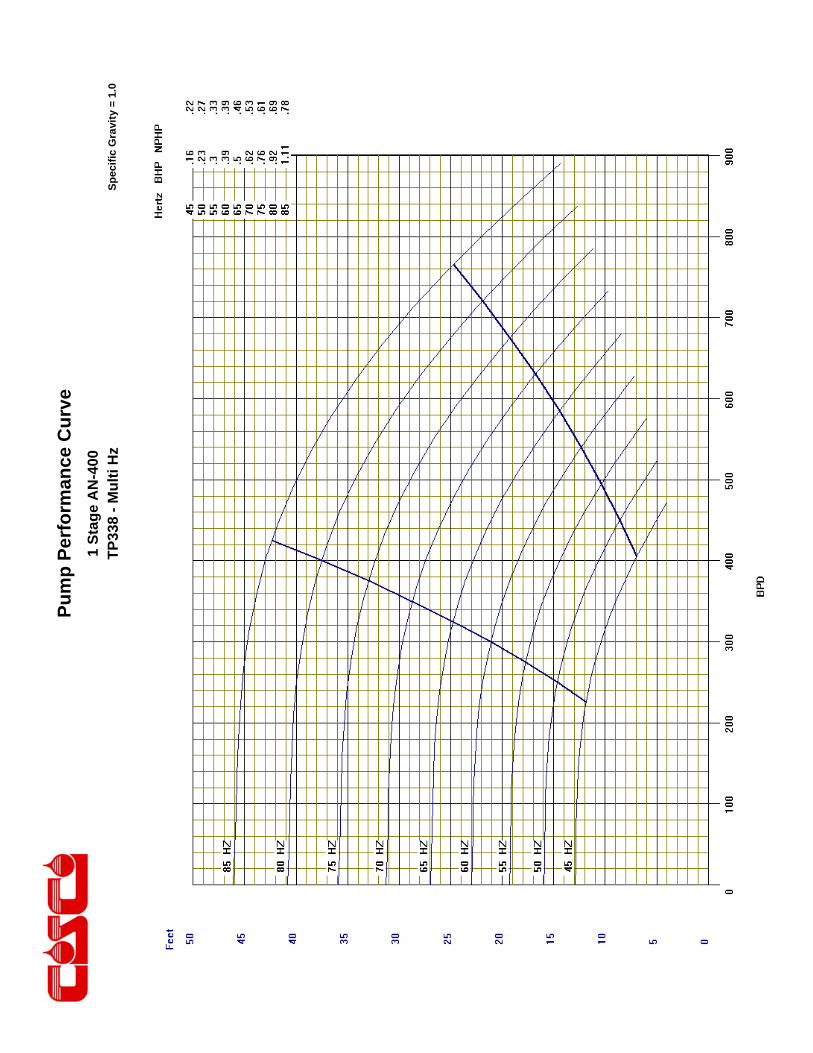
This engineering performance curve represents nominal performance based on actual mul ‐stage tes ng and cer fica on. All pumps supplied by COSCO will be tested and cer fied to perform within the acceptable limits for head, horsepower, and efficiency as defined in the “API RECOMMENDED PRACTICE(11S2) FOR ELECTRIC SUBMERSIBLE PUMP TESTING”.
COSCO 338 Series Pumps
ENGINEERING DATA
Housing Diameter 3.38 inches Maximum Staging: Shaft
Minimum Casing Size 4 1/2 Inch Shaft Type
Fluid Specific Gravity for Pump Curves 1.0 50 Hz 60 Hz
Rotational Direction CCW Standard Shaft 1229 854
Shaft Details HSS 1962 1363
Shaft Diameter 5/8 0.625 Inches Housing Pressure Limit 5000 PSI
Shaft Area 0.307 Sq. Inches Maximum Staging: Thrust Bearings (250F BHT)
Shaft Limits Bearing Type
No of Stages @
Shaft Limit in HP at: 50 Hz 60 Hz 50 Hz 60 Hz
Standard Shaft Limit 78 94 Standard Bearing 434 361
High Strength (HSS) 125 150 Hi Load Bearing 1328 1036
No of Stages @

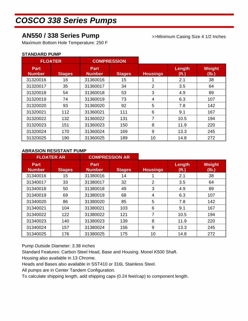
COSCO 338 Series Pumps
AN400 / 338 Series Pump >>Minimum Casing Size 4 1/2 Inches Maximum Bottom Hole Temperature: 250 F
STANDARD PUMP
FLOATER COMPRESSION
Part Number Stages
Part Number Stages Housings
Length (ft.)
Weight (lb.)
31320001 18 31360001 17 1 2.1 38
31320002 39 31360002 38 2 3.5 64
31320003 60 31360003 59 3 4.9 89
31320004 81 31360004 80 4 6.3 107
31320005 102 31360005 101 5 7.8 142
31320006 123 31360006 122 6 9.1 167
31320007 144 31360007 143 7 10.5 194
31320008 166 31360008 165 8 11.9 220
31320009 187 31360009 186 9 13.3 245
31320010 208 31360010 207 10 14.8 272
ABRASION RESISTANT PUMP
FLOATER AR COMPRESSION AR
Part Number Stages
Part Number Stages Housings
Length (ft.)
Weight (lb.)
31340001 17 31380001 16 1 2.1 38
31340002 37 31380002 36 2 3.5 64
31340003 56 31380003 55 3 4.9 89
31340004 76 31380004 75 4 6.3 107
31340005 95 31380005 94 5 7.8 142
31340006 115 31380006 114 6 9.1 167
31340007 134 31380007 133 7 10.5 194
31340008 155 31380008 154 8 11.9 220
31340009 174 31380009 173 9 13.3 245
31340010 194 31380010 193 10 14.8 272
Pump Outside Diameter: 3.38 inches Standard Features: Carbon Steel Head, Base and Housing. Monel K500 Shaft. Housing also available in 13 Chrome.
Heads and Bases also available in SST410 or 316L Stainless Steel.
All pumps are in Center Tandem Configuration. To calculate shipping length, add shipping caps (0.24 feet/cap) to component length.

Pu
mp
Per
form
ance
Cu
rve
Sp
ecif
ic G
ravi
ty =
1.0
1 S
tag
e A
N-4
00
TP
338
- 29
17 R
PM
Pu
mp
Per
form
ance
Cu
rve
Sp
ecif
ic G
ravi
ty =
1.0
1 S
tag
e A
N-4
00
TP
338
- M
ult
i Hz

This engineering performance curve represents nominal performance based on actual mul ‐stage tes ng and cer fica on. All pumps supplied by COSCO will be tested and cer fied to perform within the acceptable limits for head, horsepower, and efficiency as defined in the “API RECOMMENDED PRACTICE(11S2) FOR ELECTRIC SUBMERSIBLE PUMP TESTING”.
COSCO 338 Series Pumps
ENGINEERING DATA
Housing Diameter 3.38 inches Maximum Staging: Shaft
Minimum Casing Size 4 1/2 Inch Shaft Type
Fluid Specific Gravity for Pump Curves 1.0 50 Hz 60 Hz
Rotational Direction CCW Standard Shaft 855 594
Shaft Details HSS 1366 949
Shaft Diameter 5/8 0.625 Inches Housing Pressure Limit 5000 PSI
Shaft Area 0.3068 Sq. Inches Maximum Staging: Thrust Bearings (250F BHT)
Shaft Limits Bearing Type
No of Stages @
Shaft Limit in HP at: 50 Hz 60 Hz 50 Hz 60 Hz
Standard Shaft Limit 78 94 Standard Bearing 422 351
High Strength (HSS) 125 150 Hi Load Bearing 1291 1007
No of Stages @
COSCO 338 Series Pumps
AN550 / 338 Series Pump >>Minimum Casing Size 4 1/2 Inches Maximum Bottom Hole Temperature: 250 F
STANDARD PUMP
FLOATER COMPRESSION
Part Number Stages
Part Number Stages Housings
Length (ft.)
Weight (lb.)
31320016 16 31360016 15 1 2.1 38
31320017 35 31360017 34 2 3.5 64
31320018 54 31360018 53 3 4.9 89
31320019 74 31360019 73 4 6.3 107
31320020 93 31360020 92 5 7.8 142
31320021 112 31360021 111 6 9.1 167
31320022 132 31360022 131 7 10.5 194
31320023 151 31360023 150 8 11.9 220
31320024 170 31360024 169 9 13.3 245
31320025 190 31360025 189 10 14.8 272
ABRASION RESISTANT PUMP
FLOATER AR COMPRESSION AR
Part Number Stages
Part Number Stages Housings
Length (ft.)
Weight (lb.)
31340016 15 31380016 14 1 2.1 38
31340017 33 31380017 32 2 3.5 64
31340018 50 31380018 49 3 4.9 89
31340019 69 31380019 68 4 6.3 107
31340020 86 31380020 85 5 7.8 142
31340021 104 31380021 103 6 9.1 167
31340022 122 31380022 121 7 10.5 194
31340023 140 31380023 139 8 11.9 220
31340024 157 31380024 156 9 13.3 245
31340025 176 31380025 175 10 14.8 272
Pump Outside Diameter: 3.38 inches Standard Features: Carbon Steel Head, Base and Housing. Monel K500 Shaft. Housing also available in 13 Chrome.
Heads and Bases also available in SST410 or 316L Stainless Steel.
All pumps are in Center Tandem Configuration. To calculate shipping length, add shipping caps (0.24 feet/cap) to component length.

Pu
mp
Per
form
ance
Cu
rve
Sp
ecif
ic G
ravi
ty =
1.0
1 S
tag
e A
N-5
50
TP
338
- 29
17 R
PM
Lift
in F
T
Pu
mp
Per
form
ance
Cu
rve
Sp
ecif
ic G
ravi
ty =
1.0
1 S
tag
e A
N-5
50
TP
338
- M
ult
i Hz
Lift
in F
T

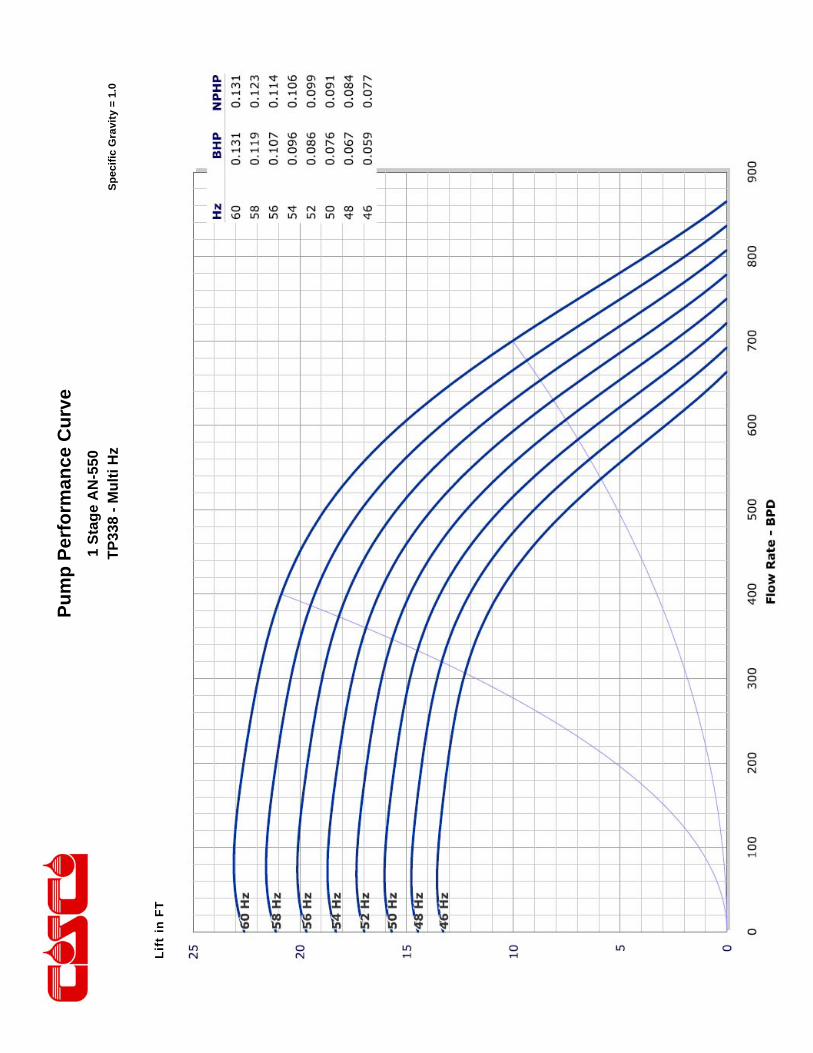
This engineering performance curve represents nominal performance based on actual mul ‐stage tes ng and cer fica on. All pumps supplied by COSCO will be tested and cer fied to perform within the acceptable limits for head, horsepower, and efficiency as defined in the “API RECOMMENDED PRACTICE(11S2) FOR ELECTRIC SUBMERSIBLE PUMP TESTING”.
COSCO 338 Series Pumps
ENGINEERING DATA
Housing Diameter 3.38 inches Maximum Staging: Shaft
Minimum Casing Size 4 1/2 Inch Shaft Type
Fluid Specific Gravity for Pump Curves 1.0 50 Hz 60 Hz
Rotational Direction CCW Standard Shaft 835 580
Shaft Details HSS 1332 925
Shaft Diameter 5/8 0.625 Inches Housing Pressure Limit 5000 PSI
Shaft Area 0.3068 Sq. Inches Maximum Staging: Thrust Bearings (250F BHT)
Shaft Limits Bearing Type
No of Stages @
Shaft Limit in HP at: 50 Hz 60 Hz 50 Hz 60 Hz
Standard Shaft Limit 78 94 Standard Bearing 439 365
High Strength (HSS) 125 150 Hi Load Bearing 1343 1047
No of Stages @
COSCO 338 Series Pumps
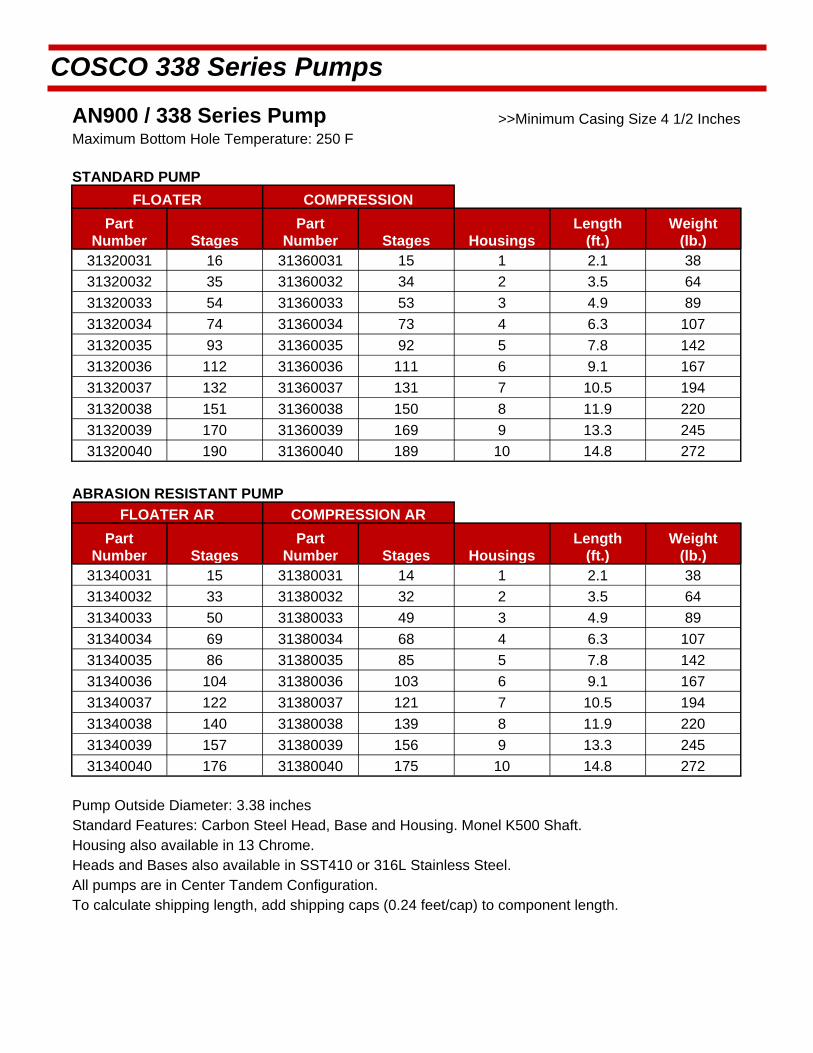
AN900 / 338 Series Pump >>Minimum Casing Size 4 1/2 Inches Maximum Bottom Hole Temperature: 250 F
STANDARD PUMP
FLOATER COMPRESSION
Part Number Stages
Part Number Stages Housings
Length (ft.)
Weight (lb.)
31320031 16 31360031 15 1 2.1 38
31320032 35 31360032 34 2 3.5 64
31320033 54 31360033 53 3 4.9 89
31320034 74 31360034 73 4 6.3 107
31320035 93 31360035 92 5 7.8 142
31320036 112 31360036 111 6 9.1 167
31320037 132 31360037 131 7 10.5 194
31320038 151 31360038 150 8 11.9 220
31320039 170 31360039 169 9 13.3 245
31320040 190 31360040 189 10 14.8 272
ABRASION RESISTANT PUMP
FLOATER AR COMPRESSION AR
Part Number Stages
Part Number Stages Housings
Length (ft.)
Weight (lb.)
31340031 15 31380031 14 1 2.1 38
31340032 33 31380032 32 2 3.5 64
31340033 50 31380033 49 3 4.9 89
31340034 69 31380034 68 4 6.3 107
31340035 86 31380035 85 5 7.8 142
31340036 104 31380036 103 6 9.1 167
31340037 122 31380037 121 7 10.5 194
31340038 140 31380038 139 8 11.9 220
31340039 157 31380039 156 9 13.3 245
31340040 176 31380040 175 10 14.8 272
Pump Outside Diameter: 3.38 inches Standard Features: Carbon Steel Head, Base and Housing. Monel K500 Shaft. Housing also available in 13 Chrome.
Heads and Bases also available in SST410 or 316L Stainless Steel.
All pumps are in Center Tandem Configuration. To calculate shipping length, add shipping caps (0.24 feet/cap) to component length.

Pu
mp
Per
form
ance
Cu
rve
Sp
ecif
ic G
ravi
ty =
1.0
1 S
tag
e A
N-9
00
TP
338
- 29
17 R
PM
Lift
in F
T
Pu
mp
Per
form
ance
Cu
rve
Sp
ecif
ic G
ravi
ty =
1.0
1 S
tag
e A
N-9
00
TP
338
- M
ult
i Hz
Lift
in F
T

This engineering performance curve represents nominal performance based on actual mul ‐stage tes ng and cer fica on. All pumps supplied by COSCO will be tested and cer fied to perform within the acceptable limits for head, horsepower, and efficiency as defined in the “API RECOMMENDED PRACTICE(11S2) FOR ELECTRIC SUBMERSIBLE PUMP TESTING”.
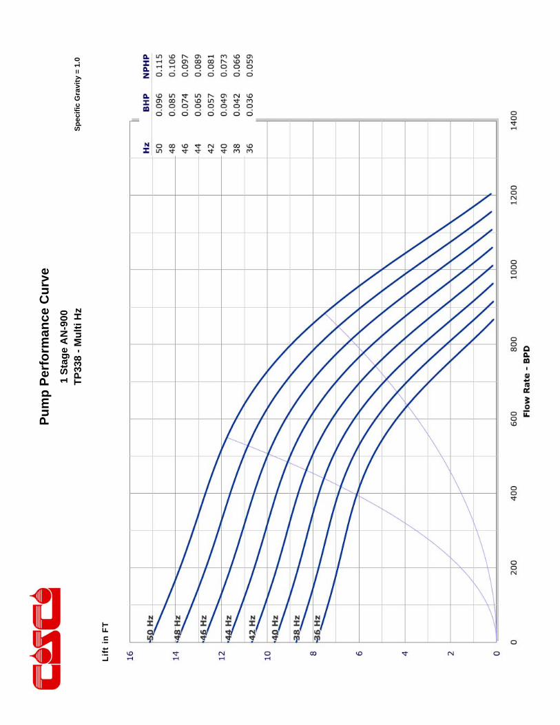
COSCO 338 Series Pumps
ENGINEERING DATA
Housing Diameter 3.38 inches Maximum Staging: Shaft
Minimum Casing Size 4 1/2 Inch Shaft Type
Fluid Specific Gravity for Pump Curves 1.0 50 Hz 60 Hz
Rotational Direction CCW Standard Shaft 525 365
Shaft Details HSS 839 583
Shaft Diameter 5/8 0.625 Inches Housing Pressure Limit 5000 PSI
Shaft Area 0.3068 Sq. Inches Maximum Staging: Thrust Bearings (250F BHT)
Shaft Limits Bearing Type
No of Stages @
Shaft Limit in HP at: 50 Hz 60 Hz 50 Hz 60 Hz
Standard Shaft Limit 78 94 Standard Bearing 447 372
High Strength (HSS) 125 150 Hi Load Bearing 1367 1067
No of Stages @
COSCO 338 Series Pumps
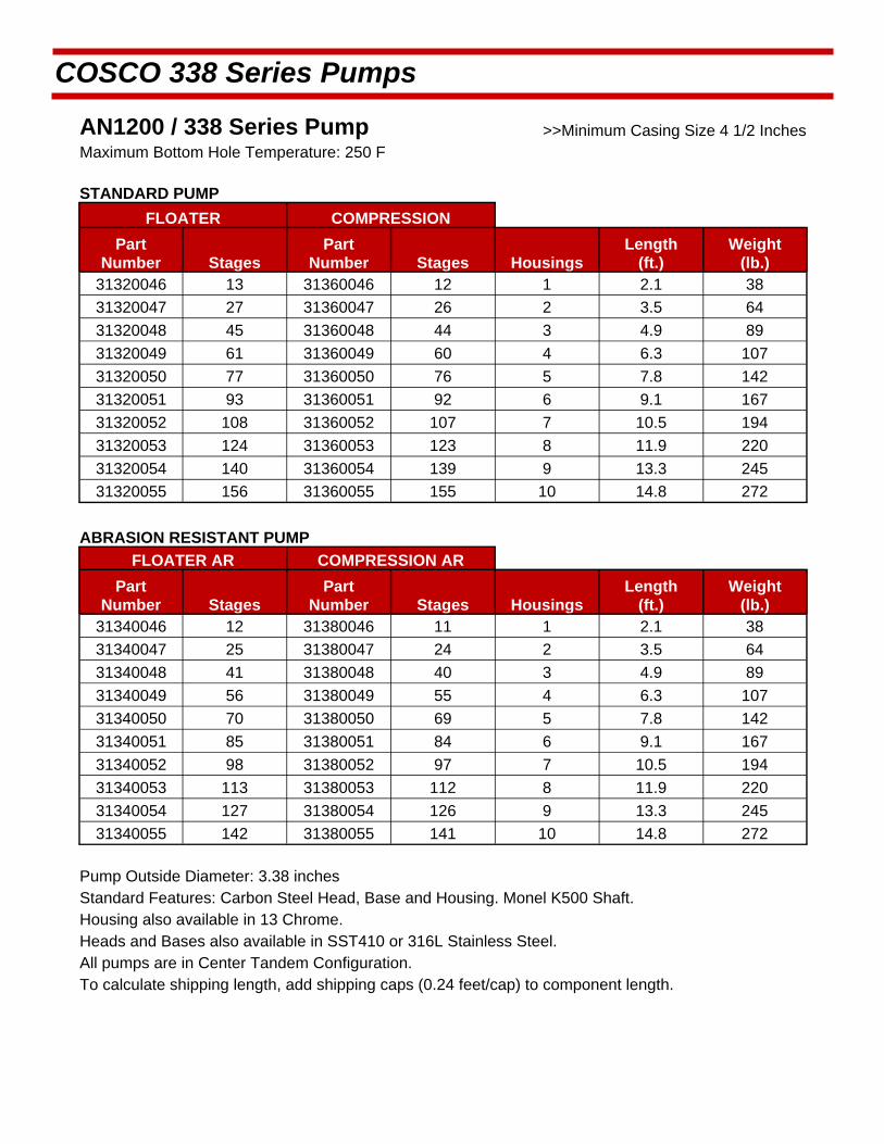
AN1200 / 338 Series Pump >>Minimum Casing Size 4 1/2 Inches Maximum Bottom Hole Temperature: 250 F
STANDARD PUMP
FLOATER COMPRESSION
Part Number Stages
Part Number Stages Housings
Length (ft.)
Weight (lb.)
31320046 13 31360046 12 1 2.1 38
31320047 27 31360047 26 2 3.5 64
31320048 45 31360048 44 3 4.9 89
31320049 61 31360049 60 4 6.3 107
31320050 77 31360050 76 5 7.8 142
31320051 93 31360051 92 6 9.1 167
31320052 108 31360052 107 7 10.5 194
31320053 124 31360053 123 8 11.9 220
31320054 140 31360054 139 9 13.3 245
31320055 156 31360055 155 10 14.8 272
ABRASION RESISTANT PUMP
FLOATER AR COMPRESSION AR
Part Number Stages
Part Number Stages Housings
Length (ft.)
Weight (lb.)
31340046 12 31380046 11 1 2.1 38
31340047 25 31380047 24 2 3.5 64
31340048 41 31380048 40 3 4.9 89
31340049 56 31380049 55 4 6.3 107
31340050 70 31380050 69 5 7.8 142
31340051 85 31380051 84 6 9.1 167
31340052 98 31380052 97 7 10.5 194
31340053 113 31380053 112 8 11.9 220
31340054 127 31380054 126 9 13.3 245
31340055 142 31380055 141 10 14.8 272
Pump Outside Diameter: 3.38 inches Standard Features: Carbon Steel Head, Base and Housing. Monel K500 Shaft. Housing also available in 13 Chrome.
Heads and Bases also available in SST410 or 316L Stainless Steel.
All pumps are in Center Tandem Configuration. To calculate shipping length, add shipping caps (0.24 feet/cap) to component length.
Pu
mp
Per
form
ance
Cu
rve
Sp
ecif
ic G
ravi
ty =
1.0
1 S
tag
e A
N-1
200
TP
338
- 29
17 R
PM
Lift
in F
T
Pu
mp
Per
form
ance
Cu
rve
Sp
ecif
ic G
ravi
ty =
1.0
1 S
tag
e A
N-1
200
TP
338
- M
ult
i Hz
Lift
in F
T
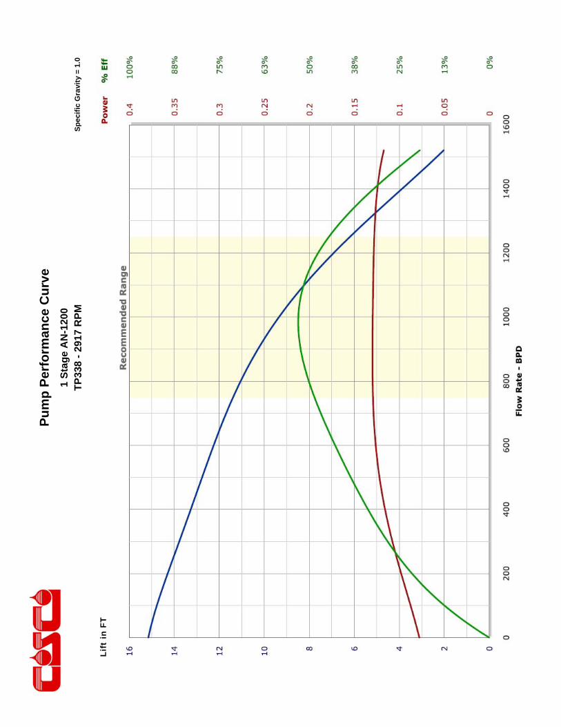
This engineering performance curve represents nominal performance based on actual mul ‐stage tes ng and cer fica on. All pumps supplied by COSCO will be tested and cer fied to perform within the acceptable limits for head, horsepower, and efficiency as defined in the “API RECOMMENDED PRACTICE(11S2) FOR ELECTRIC SUBMERSIBLE PUMP TESTING”.
COSCO 338 Series Pumps
ENGINEERING DATA
Housing Diameter 3.38 inches Maximum Staging: Shaft
Minimum Casing Size 4 1/2 Inch Shaft Type
Fluid Specific Gravity for Pump Curves 1.0 50 Hz 60 Hz
Rotational Direction CCW Standard Shaft 544 378
Shaft Details HSS 872 606
Shaft Diameter 11/16 0.6875 Inches Housing Pressure Limit 5000 PSI
Shaft Area 0.3712 Sq. Inches Maximum Staging: Thrust Bearings (250F BHT)
Shaft Limits Bearing Type
No of Stages @
Shaft Limit in HP at: 50 Hz 60 Hz 50 Hz 60 Hz
Standard Shaft Limit 105 125 Standard Bearing 440 366
High Strength (HSS) 168 200 Hi Load Bearing 1346 1050
No of Stages @

COSCO 338 Series Pumps
AN1500 / 338 Series Pump >>Minimum Casing Size 4 1/2 Inches Maximum Bottom Hole Temperature: 250 F
STANDARD PUMP
FLOATER COMPRESSION
Part Number Stages
Part Number Stages Housings
Length (ft.)
Weight (lb.)
31320061 10 31360061 9 1 2.1 38
31320062 23 31360062 22 2 3.5 64
31320063 35 31360063 34 3 4.9 89
31320064 48 31360064 47 4 6.3 107
31320065 60 31360065 59 5 7.8 142
31320066 73 31360066 72 6 9.1 167
31320067 85 31360067 84 7 10.5 194
31320068 98 31360068 97 8 11.9 220
31320069 110 31360069 109 9 13.3 245
31320070 123 31360070 122 10 14.8 272
ABRASION RESISTANT PUMP
FLOATER AR COMPRESSION AR
Part Number Stages
Part Number Stages Housings
Length (ft.)
Weight (lb.)
31340061 9 31380061 8 1 2.1 38
31340062 21 31380062 20 2 3.5 64
31340063 32 31380063 31 3 4.9 89
31340064 44 31380064 43 4 6.3 107
31340065 55 31380065 54 5 7.8 142
31340066 67 31380066 66 6 9.1 167
31340067 78 31380067 77 7 10.5 194
31340068 90 31380068 89 8 11.9 220
31340069 101 31380069 100 9 13.3 245
31340070 113 31380070 112 10 14.8 272
Pump Outside Diameter: 3.38 inches Standard Features: Carbon Steel Head, Base and Housing. Monel K500 Shaft. Housing also available in 13 Chrome.
Heads and Bases also available in SST410 or 316L Stainless Steel.
All pumps are in Center Tandem Configuration. To calculate shipping length, add shipping caps (0.24 feet/cap) to component length.
Pu
mp
Per
form
ance
Cu
rve
Sp
ecif
ic G
ravi
ty =
1.0
1 S
tag
e A
N-1
500
TP
338
- 29
17 R
PM
Lift
in F
T
Pu
mp
Per
form
ance
Cu
rve
Sp
ecif
ic G
ravi
ty =
1.0
1 S
tag
e A
N-1
500
TP
338
- M
ult
i Hz
Lift
in F
T

This engineering performance curve represents nominal performance based on actual mul ‐stage tes ng and cer fica on. All pumps supplied by COSCO will be tested and cer fied to perform within the acceptable limits for head, horsepower, and efficiency as defined in the “API RECOMMENDED PRACTICE(11S2) FOR ELECTRIC SUBMERSIBLE PUMP TESTING”.
COSCO 338 Series Pumps
ENGINEERING DATA
Housing Diameter 3.38 inches Maximum Staging: Shaft
Minimum Casing Size 4 1/2 Inch Shaft Type
Fluid Specific Gravity for Pump Curves 1.0 50 Hz 60 Hz
Rotational Direction CCW Standard Shaft 322 223
Shaft Details HSS 516 357
Shaft Diameter 11/16 0.6875 Inches Housing Pressure Limit 5000 PSI
Shaft Area 0.3712 Sq. Inches Maximum Staging: Thrust Bearings (250F BHT)
Shaft Limits Bearing Type
No of Stages @
Shaft Limit in HP at: 50 Hz 60 Hz 50 Hz 60 Hz
Standard Shaft Limit 105 125 Standard Bearing 336 280
High Strength (HSS) 168 200 Hi Load Bearing 1028 803
No of Stages @
COSCO 338 Series Pumps
AN2500 / 338 Series Pump >>Minimum Casing Size 4 1/2 Inches Maximum Bottom Hole Temperature: 250 F
STANDARD PUMP
FLOATER COMPRESSION
Part Number Stages
Part Number Stages Housings
Length (ft.)
Weight (lb.)
31320076 4 31360076 3 1 2.1 38
31320077 10 31360077 9 2 3.5 64
31320078 15 31360078 14 3 4.9 89
31320079 21 31360079 20 4 6.3 107
31320080 26 31360080 25 5 7.8 142
31320081 31 31360081 30 6 9.1 167
31320082 37 31360082 36 7 10.5 194
31320083 42 31360083 41 8 11.9 220
31320084 48 31360084 47 9 13.3 245
31320085 53 31360085 52 10 14.8 272
ABRASION RESISTANT PUMP
FLOATER AR COMPRESSION AR
Part Number Stages
Part Number Stages Housings
Length (ft.)
Weight (lb.)
31340076 4 31380076 3 1 2.1 38
31340077 10 31380077 9 2 3.5 64
31340078 15 31380078 14 3 4.9 89
31340079 21 31380079 20 4 6.3 107
31340080 26 31380080 25 5 7.8 142
31340081 31 31380081 30 6 9.1 167
31340082 37 31380082 36 7 10.5 194
31340083 42 31380083 41 8 11.9 220
31340084 48 31380084 47 9 13.3 245
31340085 53 31380085 52 10 14.8 272
Pump Outside Diameter: 3.38 inches Standard Features: Carbon Steel Head, Base and Housing. Monel K500 Shaft. Housing also available in 13 Chrome.
Heads and Bases also available in SST410 or 316L Stainless Steel.
All pumps are in Center Tandem Configuration. To calculate shipping length, add shipping caps (0.24 feet/cap) to component length.

Pu
mp
Per
form
ance
Cu
rve
Sp
ecif
ic G
ravi
ty =
1.0
1 S
tag
e A
N-2
500
TP
338-
291
7 R
PM
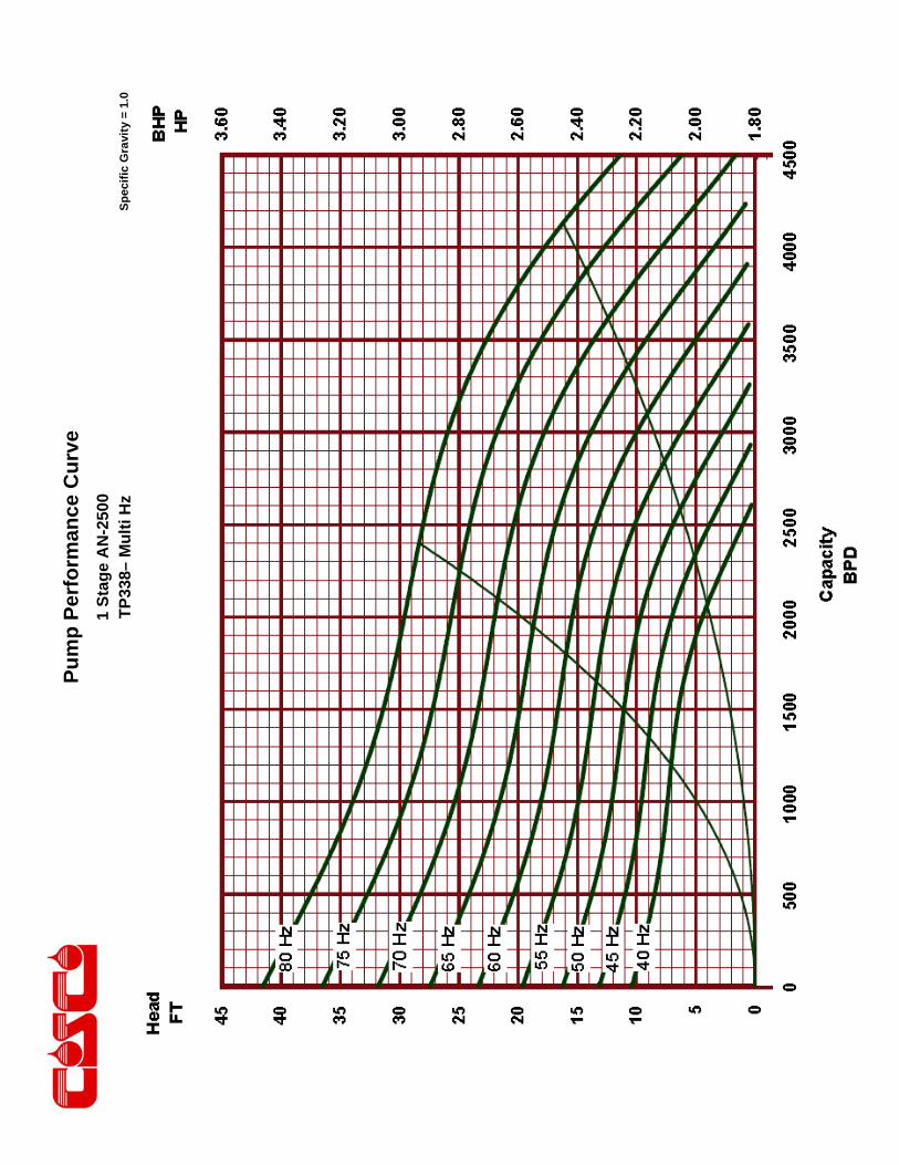
Pu
mp
Per
form
ance
Cu
rve
Sp
ecif
ic G
ravi
ty =
1.0
1 S
tag
e A
N-2
500
TP
338
- M
ult
i Hz
Lift
in F
T
1 S
tag
e A
N-2
500
TP
338–
Mu
lti H
z
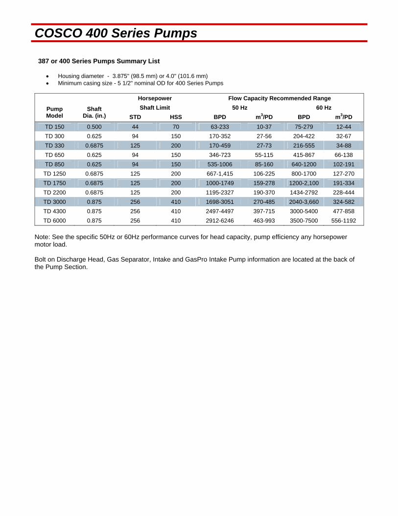
COSCO 400 Series Pumps 387 or 400 Series Pumps Summary List
Housing diameter - 3.875" (98.5 mm) or 4.0" (101.6 mm) Minimum casing size - 5 1/2" nominal OD for 400 Series Pumps
Horsepower Flow Capacity Recommended Range
Pump Model
Shaft Dia. (in.)
Shaft Limit 50 Hz 60 Hz
STD HSS BPD m3/PD BPD m3/PD
TD 150 0.500 44 70 63-233 10-37 75-279 12-44
TD 300 0.625 94 150 170-352 27-56 204-422 32-67
TD 330 0.6875 125 200 170-459 27-73 216-555 34-88
TD 650 0.625 94 150 346-723 55-115 415-867 66-138
TD 850 0.625 94 150 535-1006 85-160 640-1200 102-191
TD 1250 0.6875 125 200 667-1,415 106-225 800-1700 127-270
TD 1750 0.6875 125 200 1000-1749 159-278 1200-2,100 191-334
TD 2200 0.6875 125 200 1195-2327 190-370 1434-2792 228-444
TD 3000 0.875 256 410 1698-3051 270-485 2040-3,660 324-582
TD 4300 0.875 256 410 2497-4497 397-715 3000-5400 477-858
TD 6000 0.875 256 410 2912-6246 463-993 3500-7500 556-1192
Note: See the specific 50Hz or 60Hz performance curves for head capacity, pump efficiency any horsepower motor load. Bolt on Discharge Head, Gas Separator, Intake and GasPro Intake Pump information are located at the back of the Pump Section.
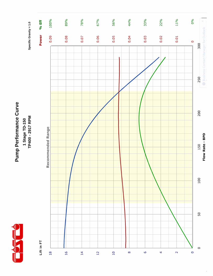
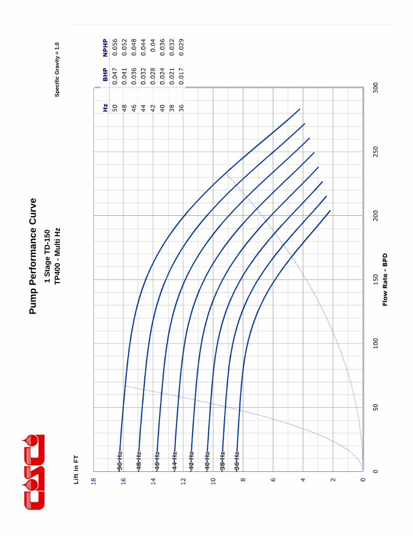
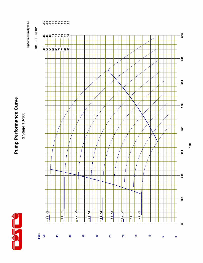
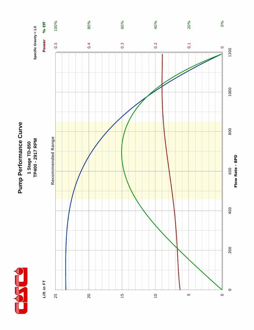
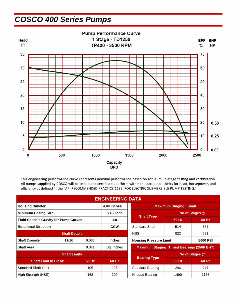
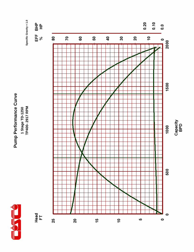
This engineering performance curve represents nominal performance based on actual mul ‐stage tes ng and cer fica on. All pumps supplied by COSCO will be tested and cer fied to perform within the acceptable limits for head, horsepower, and efficiency as defined in the “API RECOMMENDED PRACTICE(11S2) FOR ELECTRIC SUBMERSIBLE PUMP TESTING.”
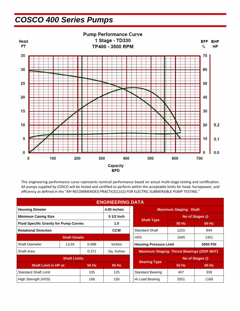
COSCO 400 Series Pumps
ENGINEERING DATA
Housing Dimeter 4.00 inches Maximum Staging: Shaft
Minimum Casing Size 5 1/2 Inch Shaft Type
Fluid Specific Gravity for Pump Curves 1.0 50 Hz 60 Hz
Rotational Direction CCW Standard Shaft 1229 440
Shaft Details HSS 1962 700
Shaft Diameter 1/2 0.500 Inches Housing Pressure Limit 5000 PSI
Shaft Area 0.1963 Sq. Inches Maximum Staging: Thrust Bearings (250F BHT)
Shaft Limits Bearing Type
No of Stages @
Shaft Limit in HP at: 50 Hz 60 Hz 50 Hz 60 Hz
Standard Shaft Limit 38 44 Standard Bearing 434 603
High Strength (HSS) 59 70 Hi Load Bearing 1328 3321
No of Stages @

COSCO 400 Series Pumps
TD150 / 400 Series Pump >>Minimum Casing Size 5 1/2 Inches Maximum Bottom Hole Temperature: 250 F
STANDARD PUMP
FLOATER COMPRESSION
Part Number Stages
Part Number Stages Housings
Length (ft.)
Weight (lb.)
31420001 19 31460001 17 1 2.1 44
31420002 39 31460002 37 2 3.5 73
31420003 60 31460003 58 3 4.8 106
31420004 80 31460004 78 4 6.3 134
31420005 101 31460005 99 5 7.8 165
31420006 122 31460006 120 6 9.2 196
31420007 142 31460007 140 7 10.6 225
31420008 163 31460008 161 8 12 258
31420009 184 31460009 182 9 13.4 287
31420010 204 31460010 202 10 14.8 317
31420011 225 31460011 223 11 16.2 348
31420012 245 31460012 243 12 17.6 377
ABRASION RESISTANT PUMP
FLOATER AR COMPRESSION AR
Part Number Stages
Part Number Stages Housings
Length (ft.)
Weight (lb.)
31440001 18 31480001 16 1 2.1 44
31440002 37 31480002 35 2 3.5 73
31440003 56 31480003 54 3 4.8 106
31440004 75 31480004 73 4 6.3 134
31440005 94 31480005 92 5 7.8 165
31440006 114 31480006 112 6 9.2 196
31440007 132 31480007 130 7 10.6 225
31440008 152 31480008 150 8 12 258
31440009 171 31480009 169 9 13.4 287
31440010 190 31480010 188 10 14.8 317
31440011 209 31480011 207 11 16.2 348
31440012 228 31480012 226 12 17.6 377
Pump Outside Diameter: 4.00 inches Standard Features: Carbon Steel Head, Base and Housing. Monel K500 Shaft. Housing also available in 13 Chrome.
Heads and Bases also available in SST410 or 316L Stainless Steel.
All pumps are in Center Tandem Configuration. To calculate shipping length, add shipping caps (0.24 feet/cap) to component length.
Pu
mp
Per
form
ance
Cu
rve
Sp
ecif
ic G
ravi
ty =
1.0
1 S
tag
e T
D-1
50
TP
400
- 29
17 R
PM
Li
ft in
FT
Pu
mp
Per
form
ance
Cu
rve
Sp
ecif
ic G
ravi
ty =
1.0
1 S
tag
e T
D-1
50
TP
400
- M
ult
i Hz
Li
ft in
FT
This engineering performance curve represents nominal performance based on actual mul ‐stage tes ng and cer fica on. All pumps supplied by COSCO will be tested and cer fied to perform within the acceptable limits for head, horsepower, and efficiency as defined in the “API RECOMMENDED PRACTICE(11S2) FOR ELECTRIC SUBMERSIBLE PUMP TESTING.”
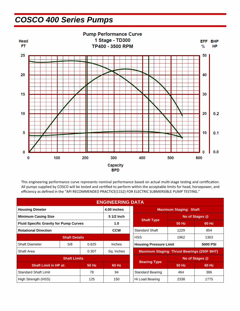
COSCO 400 Series Pumps
ENGINEERING DATA
Housing Dimeter 4.00 inches Maximum Staging: Shaft
Minimum Casing Size 5 1/2 Inch Shaft Type
Fluid Specific Gravity for Pump Curves 1.0 50 Hz 60 Hz
Rotational Direction CCW Standard Shaft 1229 854
Shaft Details HSS 1962 1363
Shaft Diameter 5/8 0.625 Inches Housing Pressure Limit 5000 PSI
Shaft Area 0.307 Sq. Inches Maximum Staging: Thrust Bearings (250F BHT)
Shaft Limits Bearing Type
No of Stages @
Shaft Limit in HP at: 50 Hz 60 Hz 50 Hz 60 Hz
Standard Shaft Limit 78 94 Standard Bearing 464 386
High Strength (HSS) 125 150 Hi Load Bearing 2338 1775
No of Stages @
COSCO 400 Series Pumps
TD300 / 400 Series Pump >>Minimum Casing Size 5 1/2 Inches Maximum Bottom Hole Temperature: 250 F
STANDARD PUMP
FLOATER COMPRESSION
Part Number Stages
Part Number Stages Housings
Length (ft.)
Weight (lb.)
31420016 15 31460016 14 1 2.1 44
31420017 32 31460017 31 2 3.5 73
31420018 49 31460018 48 3 4.8 106
31420019 66 31460019 65 4 6.3 134
31420020 83 31460020 82 5 7.8 165
31420021 99 31460021 98 6 9.2 196
31420022 117 31460022 116 7 10.6 225
31420023 133 31460023 132 8 12 258
31420024 150 31460024 149 9 13.4 287
31420025 167 31460025 166 10 14.8 317
31420026 184 31460026 183 11 16.2 348
31420027 201 31460027 200 12 17.6 377
ABRASION RESISTANT PUMP
FLOATER AR COMPRESSION AR
Part Number Stages
Part Number Stages Housings
Length (ft.)
Weight (lb.)
31440016 14 31480016 13 1 2.1 44
31440017 30 31480017 29 2 3.5 73
31440018 45 31480018 44 3 4.8 106
31440019 61 31480019 60 4 6.3 134
31440020 76 31480020 75 5 7.8 165
31440021 91 31480021 90 6 9.2 196
31440022 107 31480022 106 7 10.6 225
31440023 122 31480023 121 8 12 258
31440024 137 31480024 136 9 13.4 287
31440025 153 31480025 152 10 14.8 317
31440026 168 31480026 167 11 16.2 348
31440027 184 31480027 183 12 17.6 377
Pump Outside Diameter: 4.00 inches Standard Features: Carbon Steel Head, Base and Housing. Monel K500 Shaft. Housing also available in 13 Chrome.
Heads and Bases also available in SST410 or 316L Stainless Steel.
All pumps are in Center Tandem Configuration. To calculate shipping length, add shipping caps (0.24 feet/cap) to component length.

Pu
mp
Per
form
ance
Cu
rve
Sp
ecif
ic G
ravi
ty =
1.0
1 S
tag
e T
D-3
00
TP
400-
291
7 R
PM
Pu
mp
Per
form
ance
Cu
rve
Sp
ecif
ic G
ravi
ty =
1.0
1 S
tag
e T
D-3
00
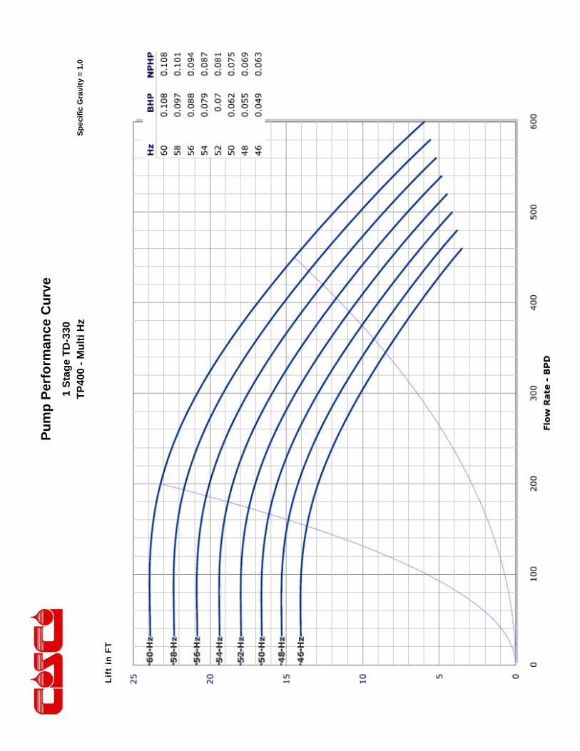
This engineering performance curve represents nominal performance based on actual mul ‐stage tes ng and cer fica on. All pumps supplied by COSCO will be tested and cer fied to perform within the acceptable limits for head, horsepower, and efficiency as defined in the “API RECOMMENDED PRACTICE(11S2) FOR ELECTRIC SUBMERSIBLE PUMP TESTING.”
COSCO 400 Series Pumps
ENGINEERING DATA
Housing Dimeter 4.00 inches Maximum Staging: Shaft
Minimum Casing Size 5 1/2 Inch Shaft Type
Fluid Specific Gravity for Pump Curves 1.0 50 Hz 60 Hz
Rotational Direction CCW Standard Shaft 1215 844
Shaft Details HSS 1945 1351
Shaft Diameter 11/16 0.688 Inches Housing Pressure Limit 5000 PSI
Shaft Area 0.371 Sq. Inches Maximum Staging: Thrust Bearings (250F BHT)
Shaft Limits Bearing Type
No of Stages @
Shaft Limit in HP at: 50 Hz 60 Hz 50 Hz 60 Hz
Standard Shaft Limit 105 125 Standard Bearing 407 339
High Strength (HSS) 168 150 Hi Load Bearing 2051 1168
No of Stages @

COSCO 400 Series Pumps
TD330 / 400 Series Pump >>Minimum Casing Size 5 1/2 Inches Maximum Bottom Hole Temperature: 250 F
STANDARD PUMP
FLOATER COMPRESSION
Part Number Stages
Part Number Stages Housings
Length (ft.)
Weight (lb.)
31420031 18 31460031 16 1 2.1 44
31420032 37 31460032 35 2 3.5 73
31420033 56 31460033 54 3 4.8 106
31420034 77 31460034 75 4 6.3 134
31420035 96 31460035 94 5 7.8 165
31420036 115 31460036 113 6 9.2 196
31420037 134 31460037 132 7 10.6 225
31420038 155 31460038 153 8 12 258
31420039 174 31460039 172 9 13.4 287
31420040 193 31460040 191 10 14.8 317
31420041 212 31460041 210 11 16.2 348
31420042 232 31460042 230 12 17.6 377
31420043 250 31460043 248 13 19 403
ABRASION RESISTANT PUMP
FLOATER AR COMPRESSION AR
Part Number Stages
Part Number Stages Housings
Length (ft.)
Weight (lb.)
31440031 17 31480031 15 1 2.1 44
31440032 35 31480032 33 2 3.5 73
31440033 52 31480033 50 3 4.8 106
31440034 72 31480034 70 4 6.3 134
31440035 89 31480035 87 5 7.8 165
31440036 107 31480036 105 6 9.2 196
31440037 124 31480037 122 7 10.6 225
31440038 144 31480038 142 8 12 258
31440039 161 31480039 159 9 13.4 287
31440040 179 31480040 177 10 14.8 317
31440041 196 31480041 194 11 16.2 348
31440042 215 31480042 213 12 17.6 377
31440043 231 31480043 229 13 19 403
Pump Outside Diameter: 4.00 inches Standard Features: Carbon Steel Head, Base and Housing. Monel K500 Shaft. Housing also available in 13 Chrome.
Heads and Bases also available in SST410 or 316L Stainless Steel.
All pumps are in Center Tandem Configuration. To calculate shipping length, add shipping caps (0.24 feet/cap) to component length.

Pu
mp
Per
form
ance
Cu
rve
Sp
ecif
ic G
ravi
ty =
1.0
1 S
tag
e T
D-3
30
TP
400
- 29
17 R
PM
Li
ft in
FT
Pu
mp
Per
form
ance
Cu
rve
Sp
ecif
ic G
ravi
ty =
1.0
1 S
tag
e T
D-3
30
TP
400
- M
ult
i Hz
Li
ft in
FT

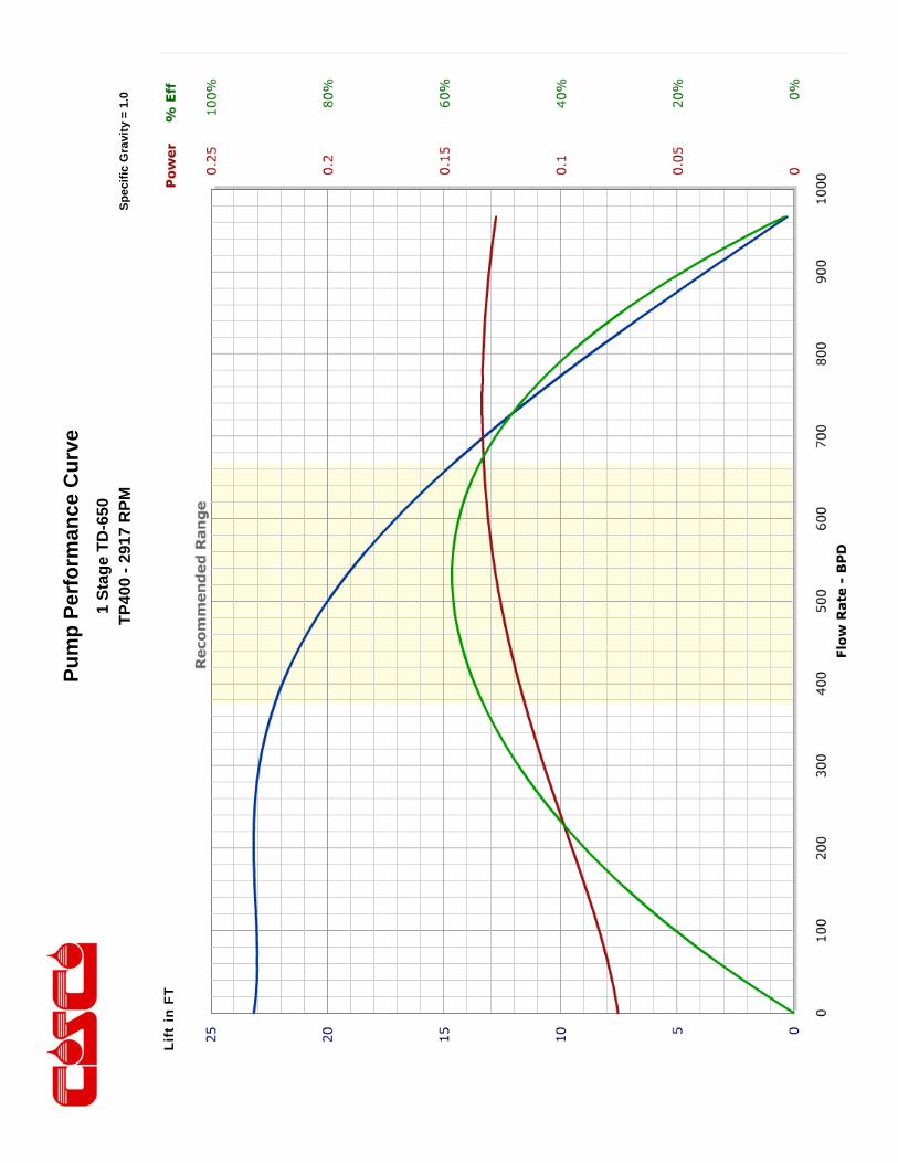
This engineering performance curve represents nominal performance based on actual mul ‐stage tes ng and cer fica on. All pumps supplied by COSCO will be tested and cer fied to perform within the acceptable limits for head, horsepower, and efficiency as defined in the “API RECOMMENDED PRACTICE(11S2) FOR ELECTRIC SUBMERSIBLE PUMP TESTING.”
COSCO 400 Series Pumps
ENGINEERING DATA
Housing Dimeter 4.00 inches Maximum Staging: Shaft
Minimum Casing Size 5 1/2 Inch Shaft Type
Fluid Specific Gravity for Pump Curves 1.0 50 Hz 60 Hz
Rotational Direction CCW Standard Shaft 482 335
Shaft Details HSS 770 535
Shaft Diameter 5/8 0.625 Inches Housing Pressure Limit 5000 PSI
Shaft Area 0.307 Sq. Inches Maximum Staging: Thrust Bearings (250F BHT)
Shaft Limits Bearing Type
No of Stages @
Shaft Limit in HP at: 50 Hz 60 Hz 50 Hz 60 Hz
Standard Shaft Limit 78 94 Standard Bearing 342 285
High Strength (HSS) 125 150 Hi Load Bearing 1723 1311
No of Stages @

COSCO 400 Series Pumps
TD650 / 400 Series Pump >>Minimum Casing Size 5 1/2 Inches Maximum Bottom Hole Temperature: 250 F
STANDARD PUMP
FLOATER COMPRESSION
Part Number Stages
Part Number Stages Housings
Length (ft.)
Weight (lb.)
31420046 18 31460046 16 1 2.1 44
31420047 37 31460047 35 2 3.5 73
31420048 56 31460048 54 3 4.8 106
31420049 76 31460049 74 4 6.3 134
31420050 95 31460050 93 5 7.8 165
31420051 114 31460051 112 6 9.2 196
31420052 133 31460052 131 7 10.6 225
31420053 153 31460053 151 8 12 258
31420054 172 31460054 170 9 13.4 287
31420055 191 31460055 189 10 14.8 317
31420056 210 31460056 208 11 16.2 348
31420057 230 31460057 228 12 17.6 377
ABRASION RESISTANT PUMP
FLOATER AR COMPRESSION AR
Part Number Stages
Part Number Stages Housings
Length (ft.)
Weight (lb.)
31440046 17 31480046 15 1 2.1 44
31440047 35 31480047 33 2 3.5 73
31440048 52 31480048 50 3 4.8 106
31440049 71 31480049 69 4 6.3 134
31440050 88 31480050 86 5 7.8 165
31440051 106 31480051 104 6 9.2 196
31440052 123 31480052 121 7 10.6 225
31440053 142 31480053 140 8 12 258
31440054 159 31480054 157 9 13.4 287
31440055 177 31480055 175 10 14.8 317
31440056 194 31480056 192 11 16.2 348
31440057 213 31480057 211 12 17.6 377
Pump Outside Diameter: 4.00 inches Standard Features: Carbon Steel Head, Base and Housing. Monel K500 Shaft. Housing also available in 13 Chrome.
Heads and Bases also available in SST410 or 316L Stainless Steel.
All pumps are in Center Tandem Configuration. To calculate shipping length, add shipping caps (0.24 feet/cap) to component length.
Pu
mp
Per
form
ance
Cu
rve
Sp
ecif
ic G
ravi
ty =
1.0
1 S
tag
e T
D-6
50
TP
400
- 29
17 R
PM
Li
ft in
FT

Pu
mp
Per
form
ance
Cu
rve
Sp
ecif
ic G
ravi
ty =
1.0
1 S
tag
e T
D-6
50
TP
400
- M
ult
i Hz
Lift
in F
T

This engineering performance curve represents nominal performance based on actual mul ‐stage tes ng and cer fica on. All pumps supplied by COSCO will be tested and cer fied to perform within the acceptable limits for head, horsepower, and efficiency as defined in the “API RECOMMENDED PRACTICE(11S2) FOR ELECTRIC SUBMERSIBLE PUMP TESTING.”
COSCO 400 Series Pumps
ENGINEERING DATA
Housing Dimeter 4.00 inches Maximum Staging: Shaft
Minimum Casing Size 5 1/2 Inch Shaft Type
Fluid Specific Gravity for Pump Curves 1.0 50 Hz 60 Hz
Rotational Direction CCW Standard Shaft 329 229
Shaft Details HSS 525 365
Shaft Diameter 5/8 0.625 Inches Housing Pressure Limit 5000 PSI
Shaft Area 0.307 Sq. Inches Maximum Staging: Thrust Bearings (250F BHT)
Shaft Limits Bearing Type
No of Stages @
Shaft Limit in HP at: 50 Hz 60 Hz 50 Hz 60 Hz
Standard Shaft Limit 78 94 Standard Bearing 307 256
High Strength (HSS) 125 150 Hi Load Bearing 1547 1177
No of Stages @

COSCO 400 Series Pumps
TD850 / 400 Series Pump >>Minimum Casing Size 5 1/2 Inches Maximum Bottom Hole Temperature: 250 F
STANDARD PUMP
FLOATER COMPRESSION
Part Number Stages
Part Number Stages Housings
Length (ft.)
Weight (lb.)
31420061 15 31460061 14 1 2.1 44
31420062 32 31460062 31 2 3.5 73
31420063 49 31460063 48 3 4.8 106
31420064 66 31460064 65 4 6.3 134
31420065 83 31460065 82 5 7.8 165
31420066 99 31460066 98 6 9.2 196
31420067 117 31460067 116 7 10.6 225
31420068 133 31460068 132 8 12 258
31420069 150 31460069 149 9 13.4 287
31420070 167 31460070 166 10 14.8 317
31420071 184 31460071 183 11 16.2 348
31420072 201 31460072 200 12 17.6 377
ABRASION RESISTANT PUMP
FLOATER AR COMPRESSION AR
Part Number Stages
Part Number Stages Housings
Length (ft.)
Weight (lb.)
31440061 14 31480061 13 1 2.1 44
31440062 30 31480062 29 2 3.5 73
31440063 45 31480063 44 3 4.8 106
31440064 61 31480064 60 4 6.3 134
31440065 76 31480065 75 5 7.8 165
31440066 91 31480066 90 6 9.2 196
31440067 107 31480067 106 7 10.6 225
31440068 122 31480068 121 8 12 258
31440069 137 31480069 136 9 13.4 287
31440070 153 31480070 152 10 14.8 317
31440071 168 31480071 167 11 16.2 348
31440072 184 31480072 183 12 17.6 377
Pump Outside Diameter: 4.00 inches Standard Features: Carbon Steel Head, Base and Housing. Monel K500 Shaft. Housing also available in 13 Chrome.
Heads and Bases also available in SST410 or 316L Stainless Steel.
All pumps are in Center Tandem Configuration. To calculate shipping length, add shipping caps (0.24 feet/cap) to component length.
Pu
mp
Per
form
ance
Cu
rve
Sp
ecif
ic G
ravi
ty =
1.0
1 S
tag
e T
D-8
50
TP
400
- 29
17 R
PM
Lift
in F
T

Pu
mp
Per
form
ance
Cu
rve
Sp
ecif
ic G
ravi
ty =
1.0
1 S
tag
e T
D-8
50
TP
400
- M
ult
i Hz
Li
ft in
FT
This engineering performance curve represents nominal performance based on actual mul ‐stage tes ng and cer fica on. All pumps supplied by COSCO will be tested and cer fied to perform within the acceptable limits for head, horsepower, and efficiency as defined in the “API RECOMMENDED PRACTICE(11S2) FOR ELECTRIC SUBMERSIBLE PUMP TESTING.”
COSCO 400 Series Pumps
ENGINEERING DATA
Housing Dimeter 4.00 inches Maximum Staging: Shaft
Minimum Casing Size 5 1/2 Inch Shaft Type
Fluid Specific Gravity for Pump Curves 1.0 50 Hz 60 Hz
Rotational Direction CCW Standard Shaft 514 357
Shaft Details HSS 822 571
Shaft Diameter 11/16 0.688 Inches Housing Pressure Limit 5000 PSI
Shaft Area 0.371 Sq. Inches Maximum Staging: Thrust Bearings (250F BHT)
Shaft Limits Bearing Type
No of Stages @
Shaft Limit in HP at: 50 Hz 60 Hz 50 Hz 60 Hz
Standard Shaft Limit 105 125 Standard Bearing 296 247
High Strength (HSS) 168 200 Hi Load Bearing 1490 1136
No of Stages @

COSCO 400 Series Pumps
TD1250 / 400 Series Pump >>Minimum Casing Size 5 1/2 Inches
Maximum Bottom Hole Temperature: 250 F
STANDARD PUMP
FLOATER COMPRESSION
Part Number
Stages Part
Number Stages Housings
Length (ft.)
Weight (lb.)
31420076 8 31460076 7 1 2.1 44 31420077 16 31460077 15 2 3.5 73 31420078 25 31460078 24 3 4.8 106 31420079 34 31460079 33 4 6.3 134 31420080 43 31460080 42 5 7.8 165 31420081 52 31460081 51 6 9.2 196 31420082 61 31460082 60 7 10.6 225 31420083 70 31460083 69 8 12 258 31420084 78 31460084 77 9 13.4 287 31420085 87 31460085 86 10 14.8 317 31420086 96 31460086 95 11 16.2 348 31420087 105 31460087 104 12 17.6 377 31420088 114 31460088 113 13 19 403 31420089 123 31460089 122 14 20.4 438 31420090 132 31460090 131 15 21.9 478
ABRASION RESISTANT PUMP
FLOATER AR COMPRESSION AR
Part Number
Stages Part
Number Stages Housings
Length (ft.)
Weight (lb.)
31440076 8 31480076 7 1 2.1 44 31440077 16 31480077 15 2 3.5 73 31440078 25 31480078 24 3 4.8 106 31440079 34 31480079 33 4 6.3 134 31440080 43 31480080 42 5 7.8 165 31440081 52 31480081 51 6 9.2 196 31440082 61 31480082 60 7 10.6 225 31440083 70 31480083 69 8 12 258 31440084 78 31480084 77 9 13.4 287 31440085 87 31480085 86 10 14.8 317 31440086 96 31480086 95 11 16.2 348 31440087 105 31480087 104 12 17.6 377 31440088 114 31480088 113 13 19 403 31440089 123 31480089 122 14 20.4 438 31440090 132 31480090 131 15 21.9 478
Pump Outside Diameter: 4.00 inches Standard Features: Carbon Steel Head, Base and Housing. Monel K500 Shaft. Housing also available in 13 Chrome.
Heads and Bases also available in SST410 or 316L Stainless Steel.
All pumps are in Center Tandem Configuration. To calculate shipping length, add shipping caps (0.24 feet/cap) to component length.
Pu
mp
Per
form
ance
Cu
rve
Sp
ecif
ic G
ravi
ty =
1.0
1 S
tag
e T
D-1
250
TP
400-
291
7 R
PM

Pu
mp
Per
form
ance
Cu
rve
Sp
ecif
ic G
ravi
ty =
1.0
1
Sta
ge
TD
-125
0 T
P40
0 -
Mu
lti H
z
Sp
ecif
ic G
ravi
ty =
1.0
This engineering performance curve represents nominal performance based on actual mul ‐stage tes ng and cer fica on. All pumps supplied by COSCO will be tested and cer fied to perform within the acceptable limits for head, horsepower, and efficiency as defined in the “API RECOMMENDED PRACTICE(11S2) FOR ELECTRIC SUBMERSIBLE PUMP TESTING.”
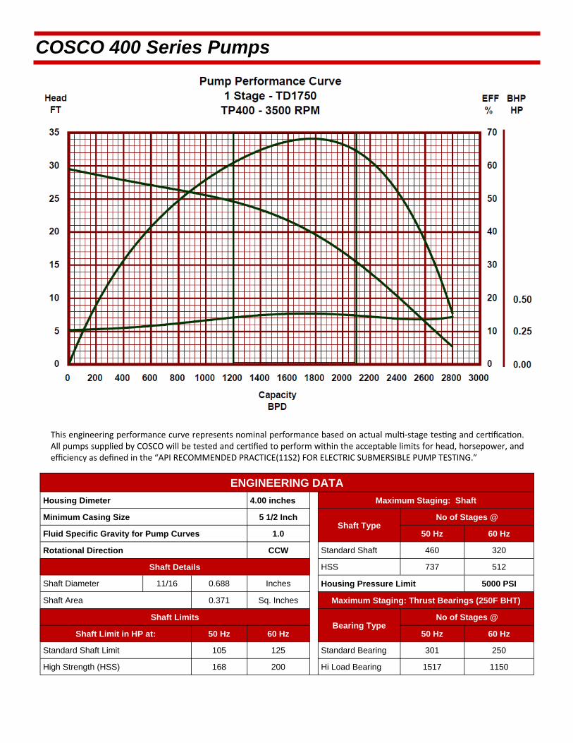
COSCO 400 Series Pumps
ENGINEERING DATA
Housing Dimeter 4.00 inches Maximum Staging: Shaft
Minimum Casing Size 5 1/2 Inch Shaft Type
Fluid Specific Gravity for Pump Curves 1.0 50 Hz 60 Hz
Rotational Direction CCW Standard Shaft 460 320
Shaft Details HSS 737 512
Shaft Diameter 11/16 0.688 Inches Housing Pressure Limit 5000 PSI
Shaft Area 0.371 Sq. Inches Maximum Staging: Thrust Bearings (250F BHT)
Shaft Limits Bearing Type
No of Stages @
Shaft Limit in HP at: 50 Hz 60 Hz 50 Hz 60 Hz
Standard Shaft Limit 105 125 Standard Bearing 301 250
High Strength (HSS) 168 200 Hi Load Bearing 1517 1150
No of Stages @

COSCO 400 Series Pumps
TD1750 / 400 Series Pump >>Minimum Casing Size 5 1/2 Inches
Maximum Bottom Hole Temperature: 250 F
STANDARD PUMP
FLOATER COMPRESSION
Part Number
Stages Part
Number Stages Housings
Length (ft.)
Weight (lb.)
31420091 8 31460091 7 1 2.1 44 31420092 16 31460092 15 2 3.5 73 31420093 24 31460093 23 3 4.8 106 31420094 33 31460094 32 4 6.3 134 31420095 41 31460095 40 5 7.8 165 31420096 50 31460096 49 6 9.2 196 31420097 58 31460097 57 7 10.6 225 31420098 67 31460098 66 8 12 258 31420099 75 31460099 74 9 13.4 287 31420100 84 31460100 83 10 14.8 317 31420101 92 31460101 91 11 16.2 348 31420102 100 31460102 99 12 17.6 377 31420103 108 31460103 107 13 19 403 31420104 116 31460104 115 14 20.4 438 31420105 125 31460105 124 15 21.9 478
ABRASION RESISTANT PUMP
FLOATER AR COMPRESSION AR
Part Number
Stages Part
Number Stages Housings
Length (ft.)
Weight (lb.)
31440091 8 31480091 7 1 2.1 44 31440092 16 31480092 15 2 3.5 73 31440093 24 31480093 23 3 4.8 106 31440094 33 31480094 32 4 6.3 134 31440095 41 31480095 40 5 7.8 165 31440096 50 31480096 49 6 9.2 196 31440097 58 31480097 57 7 10.6 225 31440098 67 31480098 66 8 12 258 31440099 75 31480099 74 9 13.4 287 31440100 84 31480100 83 10 14.8 317 31440101 92 31480101 91 11 16.2 348 31440102 100 31480102 99 12 17.6 377 31440103 108 31480103 107 13 19 403 31440104 116 31480104 115 14 20.4 438 31440105 125 31480105 124 15 21.9 478
Pump Outside Diameter: 4.00 inches Standard Features: Carbon Steel Head, Base and Housing. Monel K500 Shaft. Housing also available in 13 Chrome.
Heads and Bases also available in SST410 or 316L Stainless Steel.
All pumps are in Center Tandem Configuration. To calculate shipping length, add shipping caps (0.24 feet/cap) to component length.
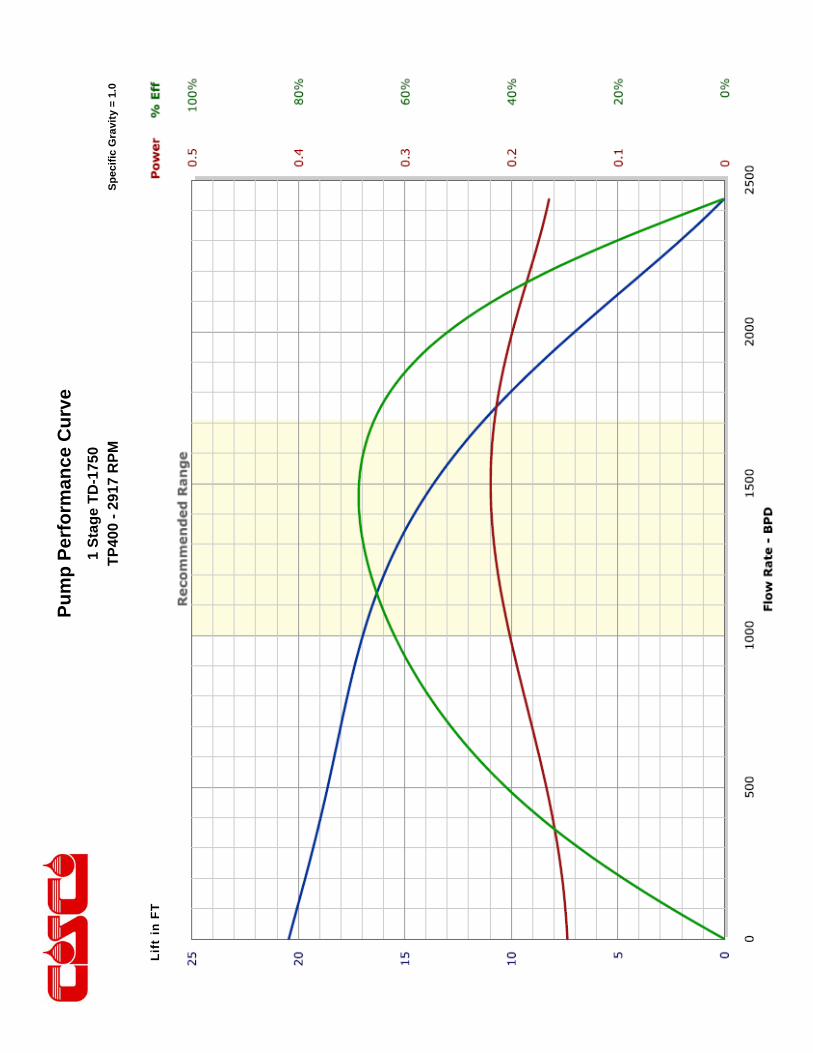
Pu
mp
Per
form
ance
Cu
rve
Sp
ecif
ic G
ravi
ty =
1.0
1 S
tag
e T
D-1
750
TP
400
- 29
17 R
PM
Li
ft in
FT
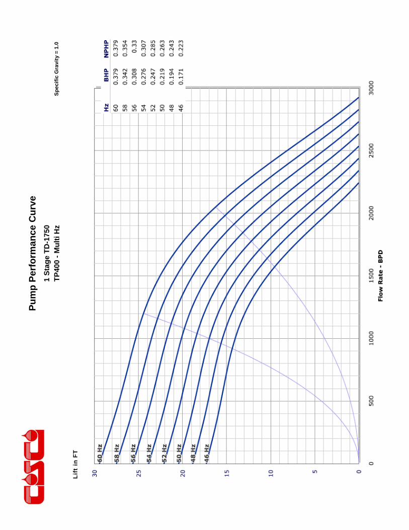
Pu
mp
Per
form
ance
Cu
rve
Sp
ecif
ic G
ravi
ty =
1.0
1 S
tag
e T
D-1
750
TP
400
- M
ult
i Hz
Li
ft in
FT

This engineering performance curve represents nominal performance based on actual mul ‐stage tes ng and cer fica on. All pumps supplied by COSCO will be tested and cer fied to perform within the acceptable limits for head, horsepower, and efficiency as defined in the “API RECOMMENDED PRACTICE(11S2) FOR ELECTRIC SUBMERSIBLE PUMP TESTING.”
COSCO 400 Series Pumps
ENGINEERING DATA
Housing Dimeter 4.00 inches Maximum Staging: Shaft
Minimum Casing Size 5 1/2 Inch Shaft Type
Fluid Specific Gravity for Pump Curves 1.0 50 Hz 60 Hz
Rotational Direction CCW Standard Shaft 315 219
Shaft Details HSS 504 350
Shaft Diameter 11/16 0.688 Inches Housing Pressure Limit 5000 PSI
Shaft Area 0.371 Sq. Inches Maximum Staging: Thrust Bearings (250F BHT)
Shaft Limits Bearing Type
No of Stages @
Shaft Limit in HP at: 50 Hz 60 Hz 50 Hz 60 Hz
Standard Shaft Limit 105 125 Standard Bearing 271 226
High Strength (HSS) 168 200 Hi Load Bearing 1365 1039
No of Stages @

COSCO 400 Series Pumps
TD2200 / 400 Series Pump >>Minimum Casing Size 5 1/2 Inches
Maximum Bottom Hole Temperature: 250 F
STANDARD PUMP
FLOATER COMPRESSION
Part Number
Stages Part
Number Stages Housings
Length (ft.)
Weight (lb.)
31420106 8 31460106 7 1 2.1 44 31420107 16 31460107 15 2 3.5 73 31420108 24 31460108 23 3 4.8 106 31420109 33 31460109 32 4 6.3 134 31420110 41 31460110 40 5 7.8 165 31420111 50 31460111 49 6 9.2 196 31420112 58 31460112 57 7 10.6 225 31420113 67 31460113 66 8 12 258 31420114 75 31460114 74 9 13.4 287 31420115 84 31460115 83 10 14.8 317 31420116 92 31460116 91 11 16.2 348 31420117 100 31460117 99 12 17.6 377 31420118 108 31460118 107 13 19 403 31420119 116 31460119 115 14 20.4 438 31420120 125 31460120 124 15 21.9 478
ABRASION RESISTANT
FLOATER AR COMPRESSION AR
Part Number
Stages Part
Number Stages Housings
Length (ft.)
Weight (lb.)
31440106 8 31480106 7 1 2.1 44 31440107 16 31480107 15 2 3.5 73 31440108 24 31480108 23 3 4.8 106 31440109 33 31480109 32 4 6.3 134 31440110 41 31480110 40 5 7.8 165 31440111 50 31480111 49 6 9.2 196 31440112 58 31480112 57 7 10.6 225 31440113 67 31480113 66 8 12 258 31440114 75 31480114 74 9 13.4 287 31440115 84 31480115 83 10 14.8 317 31440116 92 31480116 91 11 16.2 348 31440117 100 31480117 99 12 17.6 377 31440118 108 31480118 107 13 19 403 31440119 116 31480119 115 14 20.4 438 31440120 125 31480120 124 15 21.9 478
Pump Outside Diameter: 4.00 inches Standard Features: Carbon Steel Head, Base and Housing. Monel K500 Shaft. Housing also available in 13 Chrome.
Heads and Bases also available in SST410 or 316L Stainless Steel.
All pumps are in Center Tandem Configuration. To calculate shipping length, add shipping caps (0.24 feet/cap) to component length.
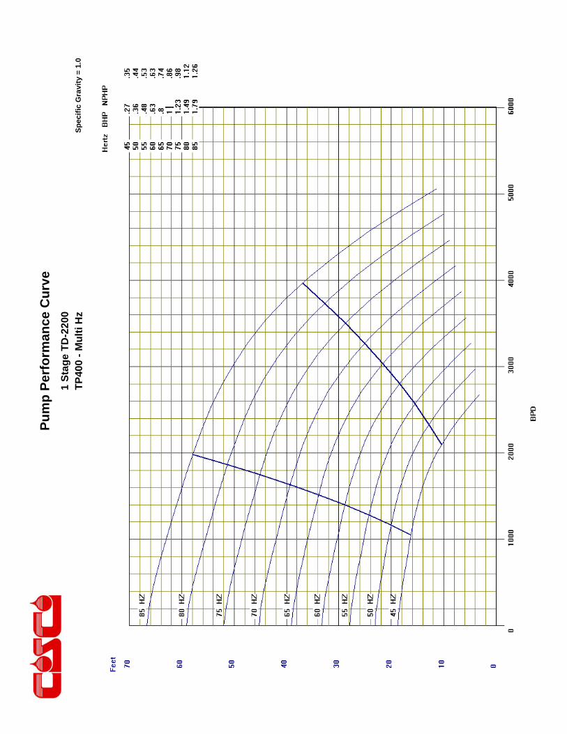
Pu
mp
Per
form
ance
Cu
rve
Sp
ecif
ic G
ravi
ty =
1.0
1 S
tag
e T
D-2
200
TP
400
- M
ult
i Hz
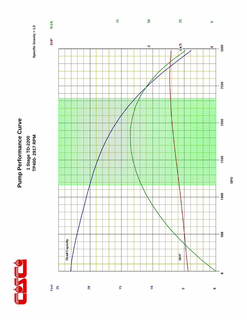
Pu
mp
Per
form
ance
Cu
rve
Sp
ecif
ic G
ravi
ty =
1.0
1 S
tag
e T
D-2
200
TP
400-
291
7 R
PM

This engineering performance curve represents nominal performance based on actual mul ‐stage tes ng and cer fica on. All pumps supplied by COSCO will be tested and cer fied to perform within the acceptable limits for head, horsepower, and efficiency as defined in the “API RECOMMENDED PRACTICE(11S2) FOR ELECTRIC SUBMERSIBLE PUMP TESTING.”
COSCO 400 Series Pumps
ENGINEERING DATA
Housing Dimeter 4.00 inches Maximum Staging: Shaft
Minimum Casing Size 5 1/2 Inch Shaft Type
Fluid Specific Gravity for Pump Curves 1.0 50 Hz 60 Hz
Rotational Direction CCW Standard Shaft 613 426
Shaft Details HSS 983 683
Shaft Diameter 7/8 0.875 Inches Housing Pressure Limit 5000 PSI
Shaft Area 0.601 Sq. Inches Maximum Staging: Thrust Bearings (250F BHT)
Shaft Limits Bearing Type
No of Stages @
Shaft Limit in HP at: 50 Hz 60 Hz 50 Hz 60 Hz
Standard Shaft Limit 213 256 Standard Bearing 194 162
High Strength (HSS) 342 410 Hi Load Bearing 977 745
No of Stages @
COSCO 400 Series Pumps
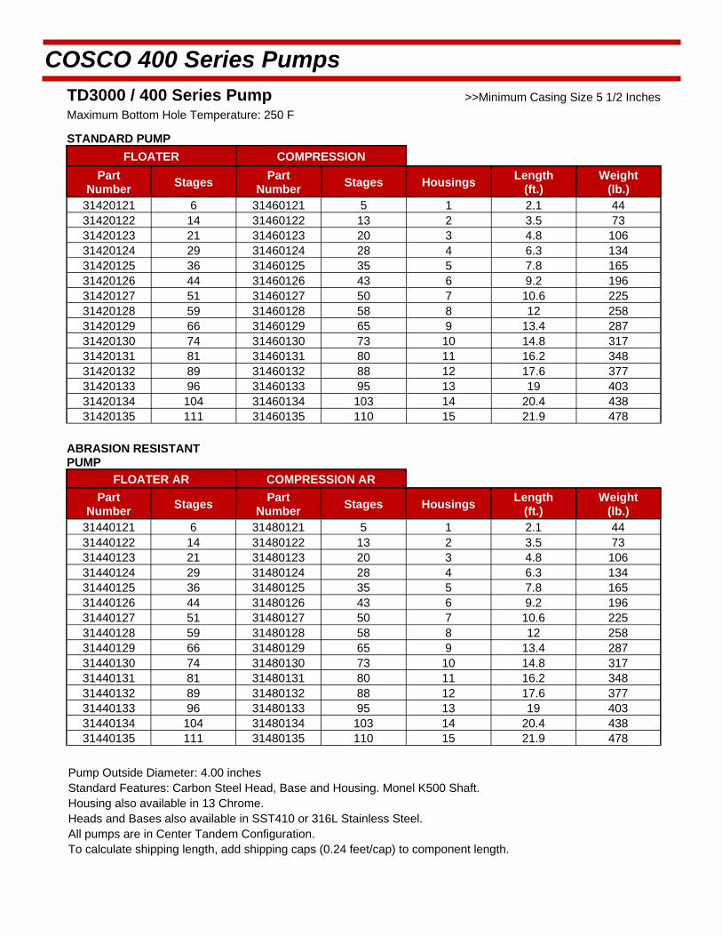
TD3000 / 400 Series Pump >>Minimum Casing Size 5 1/2 Inches
Maximum Bottom Hole Temperature: 250 F
STANDARD PUMP
FLOATER COMPRESSION
Part Number
Stages Part
Number Stages Housings
Length (ft.)
Weight (lb.)
31420121 6 31460121 5 1 2.1 44 31420122 14 31460122 13 2 3.5 73 31420123 21 31460123 20 3 4.8 106 31420124 29 31460124 28 4 6.3 134 31420125 36 31460125 35 5 7.8 165 31420126 44 31460126 43 6 9.2 196 31420127 51 31460127 50 7 10.6 225 31420128 59 31460128 58 8 12 258 31420129 66 31460129 65 9 13.4 287 31420130 74 31460130 73 10 14.8 317 31420131 81 31460131 80 11 16.2 348 31420132 89 31460132 88 12 17.6 377 31420133 96 31460133 95 13 19 403 31420134 104 31460134 103 14 20.4 438 31420135 111 31460135 110 15 21.9 478
ABRASION RESISTANT PUMP
FLOATER AR COMPRESSION AR
Part Number
Stages Part
Number Stages Housings
Length (ft.)
Weight (lb.)
31440121 6 31480121 5 1 2.1 44 31440122 14 31480122 13 2 3.5 73 31440123 21 31480123 20 3 4.8 106 31440124 29 31480124 28 4 6.3 134 31440125 36 31480125 35 5 7.8 165 31440126 44 31480126 43 6 9.2 196 31440127 51 31480127 50 7 10.6 225 31440128 59 31480128 58 8 12 258 31440129 66 31480129 65 9 13.4 287 31440130 74 31480130 73 10 14.8 317 31440131 81 31480131 80 11 16.2 348 31440132 89 31480132 88 12 17.6 377 31440133 96 31480133 95 13 19 403 31440134 104 31480134 103 14 20.4 438 31440135 111 31480135 110 15 21.9 478
Pump Outside Diameter: 4.00 inches Standard Features: Carbon Steel Head, Base and Housing. Monel K500 Shaft. Housing also available in 13 Chrome.
Heads and Bases also available in SST410 or 316L Stainless Steel.
All pumps are in Center Tandem Configuration. To calculate shipping length, add shipping caps (0.24 feet/cap) to component length.
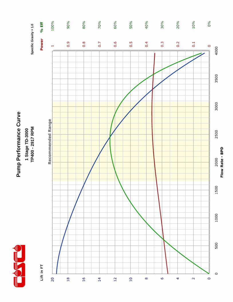
Pu
mp
Per
form
ance
Cu
rve
Sp
ecif
ic G
ravi
ty =
1.0
1 S
tag
e T
D-3
000
TP
400
- 29
17 R
PM
Lift
in F
T
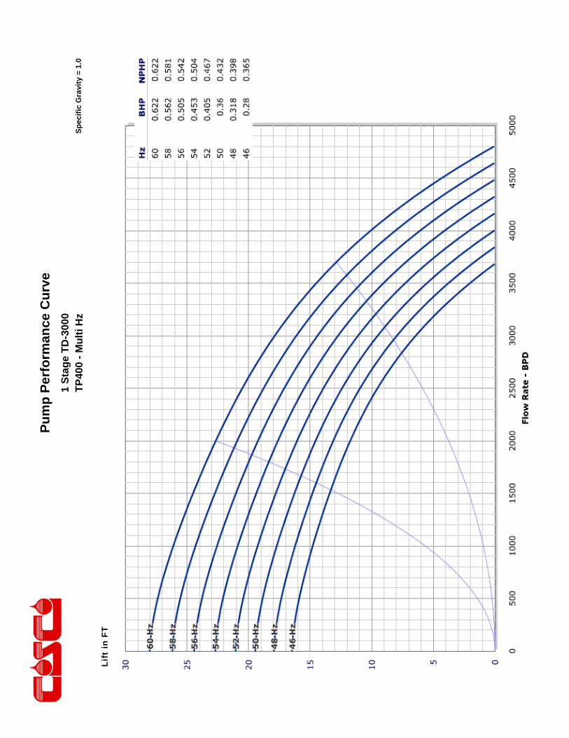
Pu
mp
Per
form
ance
Cu
rve
Sp
ecif
ic G
ravi
ty =
1.0
1 S
tag
e T
D-3
000
TP
400
- M
ult
i Hz
Li
ft in
FT
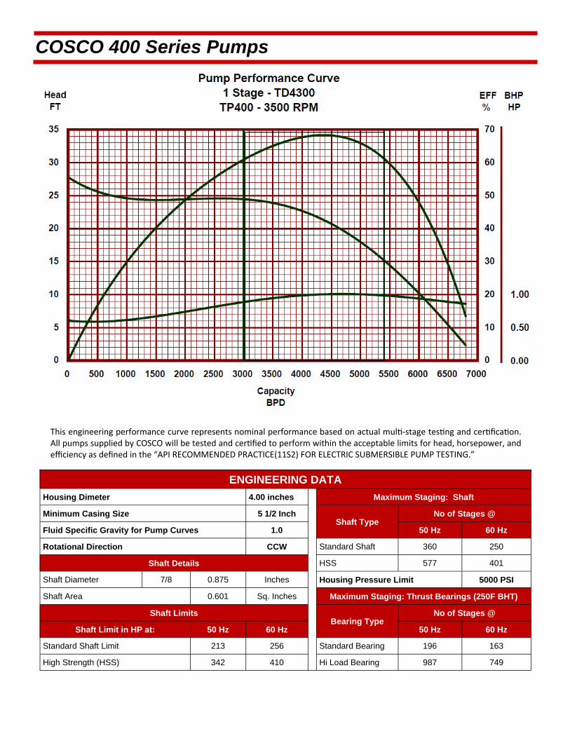
This engineering performance curve represents nominal performance based on actual mul ‐stage tes ng and cer fica on. All pumps supplied by COSCO will be tested and cer fied to perform within the acceptable limits for head, horsepower, and efficiency as defined in the “API RECOMMENDED PRACTICE(11S2) FOR ELECTRIC SUBMERSIBLE PUMP TESTING.”
COSCO 400 Series Pumps
ENGINEERING DATA
Housing Dimeter 4.00 inches Maximum Staging: Shaft
Minimum Casing Size 5 1/2 Inch Shaft Type
Fluid Specific Gravity for Pump Curves 1.0 50 Hz 60 Hz
Rotational Direction CCW Standard Shaft 360 250
Shaft Details HSS 577 401
Shaft Diameter 7/8 0.875 Inches Housing Pressure Limit 5000 PSI
Shaft Area 0.601 Sq. Inches Maximum Staging: Thrust Bearings (250F BHT)
Shaft Limits Bearing Type
No of Stages @
Shaft Limit in HP at: 50 Hz 60 Hz 50 Hz 60 Hz
Standard Shaft Limit 213 256 Standard Bearing 196 163
High Strength (HSS) 342 410 Hi Load Bearing 987 749
No of Stages @

COSCO 400 Series Pumps
TD4300 / 400 Series Pump >>Minimum Casing Size 5 1/2 Inches
Maximum Bottom Hole Temperature: 250 F
STANDARD PUMP
FLOATER COMPRESSION
Part Number
Stages Part
Number Stages Housings
Length (ft.)
Weight (lb.)
31420136 4 31460136 3 1 2.1 44 31420137 8 31460137 7 2 3.5 73 31420138 13 31460138 12 3 4.8 106 31420139 17 31460139 16 4 6.3 134 31420140 22 31460140 21 5 7.8 165 31420141 27 31460141 26 6 9.2 196 31420142 31 31460142 30 7 10.6 225 31420143 36 31460143 35 8 12 258 31420144 40 31460144 39 9 13.4 287 31420145 45 31460145 44 10 14.8 317 31420146 49 31460146 48 11 16.2 348 31420147 54 31460147 53 12 17.6 377 31420148 59 31460148 58 13 19 500 31420149 63 31460149 62 14 20.4 538 31420150 68 31460150 67 15 21.9 578
ABRASION RESISTANT
FLOATER AR COMPRESSION AR
Part Number
Stages Part
Number Stages Housings
Length (ft.)
Weight (lb.)
31440136 4 31480136 3 1 2.1 44 31440137 8 31480137 7 2 3.5 73 31440138 13 31480138 12 3 4.8 106 31440139 17 31480139 16 4 6.3 134 31440140 22 31480140 21 5 7.8 165 31440141 27 31480141 26 6 9.2 196 31440142 31 31480142 30 7 10.6 225 31440143 36 31480143 35 8 12 258 31440144 40 31480144 39 9 13.4 287 31440145 45 31480145 44 10 14.8 317 31440146 49 31480146 48 11 16.2 348 31440147 54 31480147 53 12 17.6 377 31440148 59 31480148 58 13 19 403 31440149 63 31480149 62 14 20.4 438 31440150 68 31480150 67 15 21.9 478
Pump Outside Diameter: 4.00 inches Standard Features: Carbon Steel Head, Base and Housing. Monel K500 Shaft. Housing also available in 13 Chrome.
Heads and Bases also available in SST410 or 316L Stainless Steel.
All pumps are in Center Tandem Configuration. To calculate shipping length, add shipping caps (0.24 feet/cap) to component length.
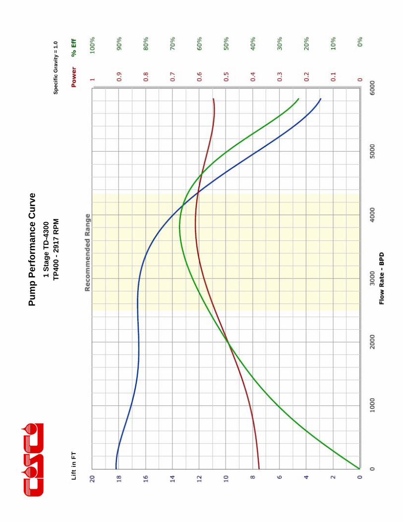
Pu
mp
Per
form
ance
Cu
rve
Sp
ecif
ic G
ravi
ty =
1.0
1 S
tag
e T
D-4
300
TP
400
- 29
17 R
PM
Li
ft in
FT

Pu
mp
Per
form
ance
Cu
rve
Sp
ecif
ic G
ravi
ty =
1.0
1 S
tag
e T
D-4
300
TP
400
- M
ult
i Hz
Lift
in F
T

This engineering performance curve represents nominal performance based on actual mul ‐stage tes ng and cer fica on. All pumps supplied by COSCO will be tested and cer fied to perform within the acceptable limits for head, horsepower, and efficiency as defined in the “API RECOMMENDED PRACTICE(11S2) FOR ELECTRIC SUBMERSIBLE PUMP TESTING.”
COSCO 400 Series Pumps
ENGINEERING DATA
Housing Dimeter 4.00 inches Maximum Staging: Shaft
Minimum Casing Size 5 1/2 Inch Shaft Type
Fluid Specific Gravity for Pump Curves 1.0 50 Hz 60 Hz
Rotational Direction CCW Standard Shaft 259 180
Shaft Details HSS 414 288
Shaft Diameter 7/8 0.875 Inches Housing Pressure Limit 5000 PSI
Shaft Area 0.601 Sq. Inches Maximum Staging: Thrust Bearings (250F BHT)
Shaft Limits Bearing Type
No of Stages @
Shaft Limit in HP at: 50 Hz 60 Hz 50 Hz 60 Hz
Standard Shaft Limit 213 256 Standard Bearing 188 157
High Strength (HSS) 342 410 Hi Load Bearing 947 722
No of Stages @
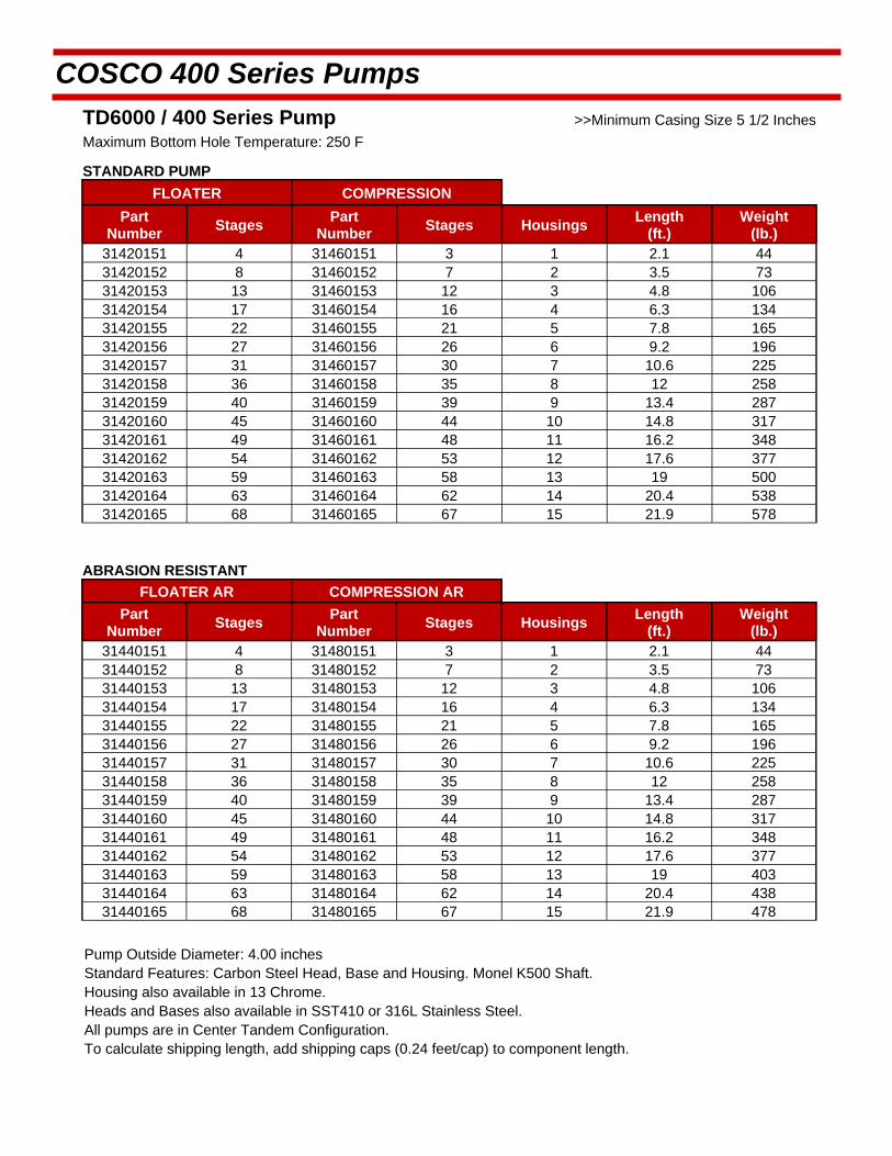
COSCO 400 Series Pumps
TD6000 / 400 Series Pump >>Minimum Casing Size 5 1/2 Inches
Maximum Bottom Hole Temperature: 250 F
STANDARD PUMP
FLOATER COMPRESSION
Part Number
Stages Part
Number Stages Housings
Length (ft.)
Weight (lb.)
31420151 4 31460151 3 1 2.1 44 31420152 8 31460152 7 2 3.5 73 31420153 13 31460153 12 3 4.8 106 31420154 17 31460154 16 4 6.3 134 31420155 22 31460155 21 5 7.8 165 31420156 27 31460156 26 6 9.2 196 31420157 31 31460157 30 7 10.6 225 31420158 36 31460158 35 8 12 258 31420159 40 31460159 39 9 13.4 287 31420160 45 31460160 44 10 14.8 317 31420161 49 31460161 48 11 16.2 348 31420162 54 31460162 53 12 17.6 377 31420163 59 31460163 58 13 19 500 31420164 63 31460164 62 14 20.4 538 31420165 68 31460165 67 15 21.9 578
ABRASION RESISTANT
FLOATER AR COMPRESSION AR
Part Number
Stages Part
Number Stages Housings
Length (ft.)
Weight (lb.)
31440151 4 31480151 3 1 2.1 44 31440152 8 31480152 7 2 3.5 73 31440153 13 31480153 12 3 4.8 106 31440154 17 31480154 16 4 6.3 134 31440155 22 31480155 21 5 7.8 165 31440156 27 31480156 26 6 9.2 196 31440157 31 31480157 30 7 10.6 225 31440158 36 31480158 35 8 12 258 31440159 40 31480159 39 9 13.4 287 31440160 45 31480160 44 10 14.8 317 31440161 49 31480161 48 11 16.2 348 31440162 54 31480162 53 12 17.6 377 31440163 59 31480163 58 13 19 403 31440164 63 31480164 62 14 20.4 438 31440165 68 31480165 67 15 21.9 478
Pump Outside Diameter: 4.00 inches Standard Features: Carbon Steel Head, Base and Housing. Monel K500 Shaft. Housing also available in 13 Chrome.
Heads and Bases also available in SST410 or 316L Stainless Steel.
All pumps are in Center Tandem Configuration. To calculate shipping length, add shipping caps (0.24 feet/cap) to component length.

Pu
mp
Per
form
ance
Cu
rve
Sp
ecif
ic G
ravi
ty =
1.0
1 S
tag
e T
D-6
000
TP
400
- 29
17 R
PM
Lift
in F
T

Pu
mp
Per
form
ance
Cu
rve
Sp
ecif
ic G
ravi
ty =
1.0
1 S
tag
e T
D-6
000
TP
400
- M
ult
i Hz
Li
ft in
FT
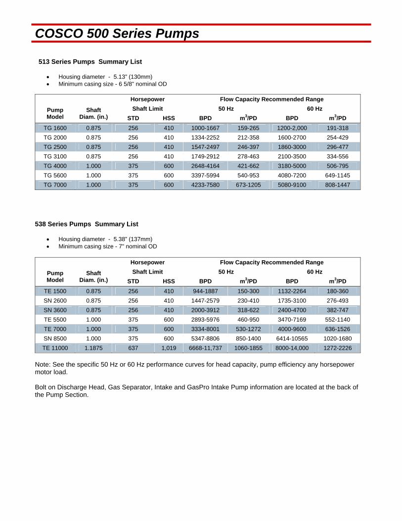
COSCO 500 Series Pumps 513 Series Pumps Summary List
Housing diameter - 5.13” (130mm) Minimum casing size - 6 5/8" nominal OD
Horsepower Flow Capacity Recommended Range
Pump Model
Shaft Diam. (in.)
Shaft Limit 50 Hz 60 Hz
STD HSS BPD m3/PD BPD m3/PD
TG 1600 0.875 256 410 1000-1667 159-265 1200-2,000 191-318
TG 2000 0.875 256 410 1334-2252 212-358 1600-2700 254-429
TG 2500 0.875 256 410 1547-2497 246-397 1860-3000 296-477
TG 3100 0.875 256 410 1749-2912 278-463 2100-3500 334-556
TG 4000 1.000 375 600 2648-4164 421-662 3180-5000 506-795
TG 5600 1.000 375 600 3397-5994 540-953 4080-7200 649-1145
TG 7000 1.000 375 600 4233-7580 673-1205 5080-9100 808-1447
538 Series Pumps Summary List
Housing diameter - 5.38” (137mm) Minimum casing size - 7" nominal OD
Horsepower Flow Capacity Recommended Range
Pump Model
Shaft Diam. (in.)
Shaft Limit 50 Hz 60 Hz
STD HSS BPD m3/PD BPD m3/PD
TE 1500 0.875 256 410 944-1887 150-300 1132-2264 180-360
SN 2600 0.875 256 410 1447-2579 230-410 1735-3100 276-493
SN 3600 0.875 256 410 2000-3912 318-622 2400-4700 382-747
TE 5500 1.000 375 600 2893-5976 460-950 3470-7169 552-1140
TE 7000 1.000 375 600 3334-8001 530-1272 4000-9600 636-1526
SN 8500 1.000 375 600 5347-8806 850-1400 6414-10565 1020-1680
TE 11000 1.1875 637 1,019 6668-11,737 1060-1855 8000-14,000 1272-2226
Note: See the specific 50 Hz or 60 Hz performance curves for head capacity, pump efficiency any horsepower motor load. Bolt on Discharge Head, Gas Separator, Intake and GasPro Intake Pump information are located at the back of the Pump Section.

This engineering performance curve represents nominal performance based on actual mul ‐stage tes ng and cer fica on. All pumps supplied by COSCO will be tested and cer fied to perform within the acceptable limits for head, horsepower, and efficiency as defined in the “API RECOMMENDED PRACTICE(11S2) FOR ELECTRIC SUBMERSIBLE PUMP TESTING.”
COSCO 513 Series Pumps
ENGINEERING DATA
Housing Dimeter 5.13 inches Maximum Staging: Shaft
Minimum Casing Size 6 5/8 Inches Shaft Type
Fluid Specific Gravity for Pump Curves 1.0 50 Hz 60 Hz
Rotational Direction CCW Standard Shaft 334 232
Shaft Details HSS 535 372
Shaft Diameter 7/8 0.875 Inches Housing Pressure Limit 5000 PSI
Shaft Area 0.6013 Sq. Inches Maximum Staging: Thrust Bearings (250F BHT)
Shaft Limits Bearing Type
No of Stages @
Shaft Limit in HP at: 50 Hz 60 Hz 50 Hz 60 Hz
Standard Shaft Limit 213 256 Standard Bearing 199 166
High Strength (HSS) 342 410 Hi Load Bearing 1100 830
No of Stages @
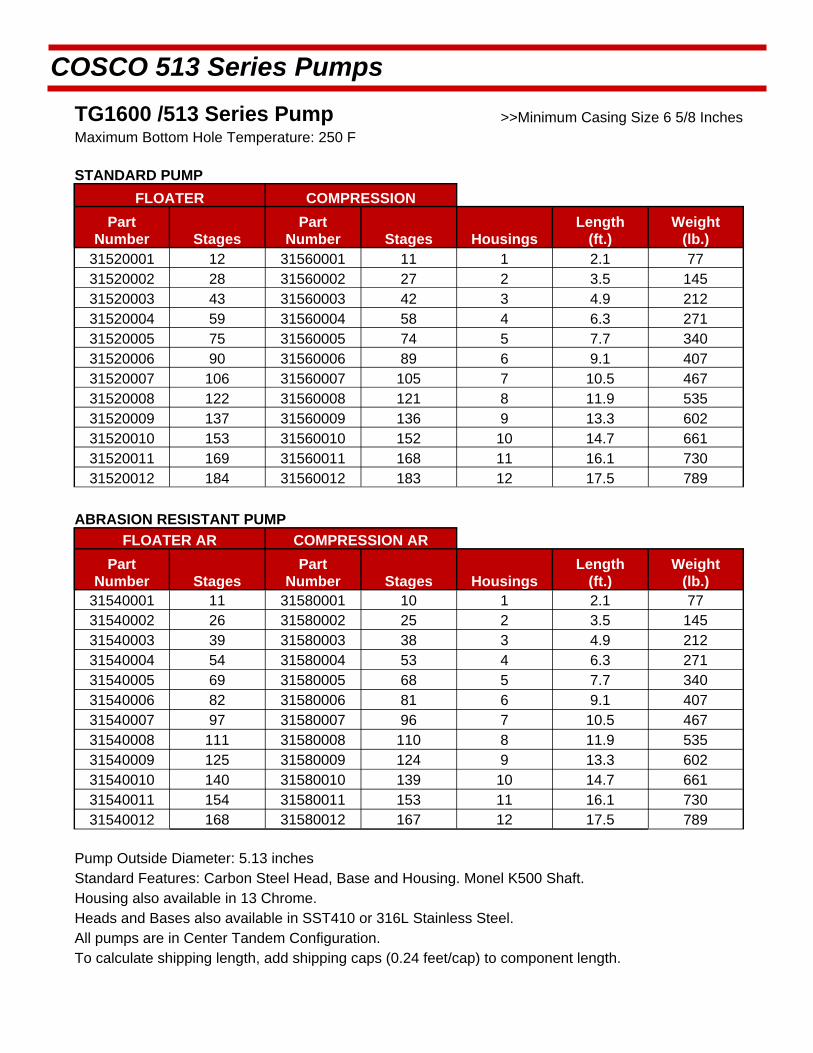
COSCO 513 Series Pumps
TG1600 /513 Series Pump >>Minimum Casing Size 6 5/8 Inches Maximum Bottom Hole Temperature: 250 F
STANDARD PUMP
FLOATER COMPRESSION
Part Number Stages
Part Number Stages Housings
Length (ft.)
Weight (lb.)
31520001 12 31560001 11 1 2.1 77 31520002 28 31560002 27 2 3.5 145 31520003 43 31560003 42 3 4.9 212 31520004 59 31560004 58 4 6.3 271 31520005 75 31560005 74 5 7.7 340 31520006 90 31560006 89 6 9.1 407 31520007 106 31560007 105 7 10.5 467 31520008 122 31560008 121 8 11.9 535 31520009 137 31560009 136 9 13.3 602 31520010 153 31560010 152 10 14.7 661 31520011 169 31560011 168 11 16.1 730 31520012 184 31560012 183 12 17.5 789
ABRASION RESISTANT PUMP
FLOATER AR COMPRESSION AR
Part Number Stages
Part Number Stages Housings
Length (ft.)
Weight (lb.)
31540001 11 31580001 10 1 2.1 77 31540002 26 31580002 25 2 3.5 145 31540003 39 31580003 38 3 4.9 212 31540004 54 31580004 53 4 6.3 271 31540005 69 31580005 68 5 7.7 340 31540006 82 31580006 81 6 9.1 407 31540007 97 31580007 96 7 10.5 467 31540008 111 31580008 110 8 11.9 535 31540009 125 31580009 124 9 13.3 602 31540010 140 31580010 139 10 14.7 661 31540011 154 31580011 153 11 16.1 730 31540012 168 31580012 167 12 17.5 789
Pump Outside Diameter: 5.13 inches Standard Features: Carbon Steel Head, Base and Housing. Monel K500 Shaft. Housing also available in 13 Chrome.
Heads and Bases also available in SST410 or 316L Stainless Steel.
All pumps are in Center Tandem Configuration. To calculate shipping length, add shipping caps (0.24 feet/cap) to component length.
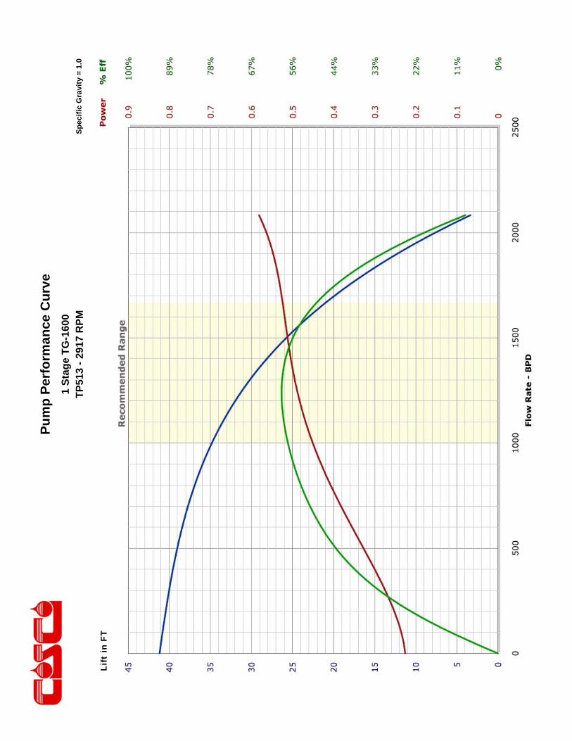
Pu
mp
Per
form
ance
Cu
rve
Sp
ecif
ic G
ravi
ty =
1.0
1 S
tag
e T
G-1
600
TP
513
- 29
17 R
PM
Lift
in F
T
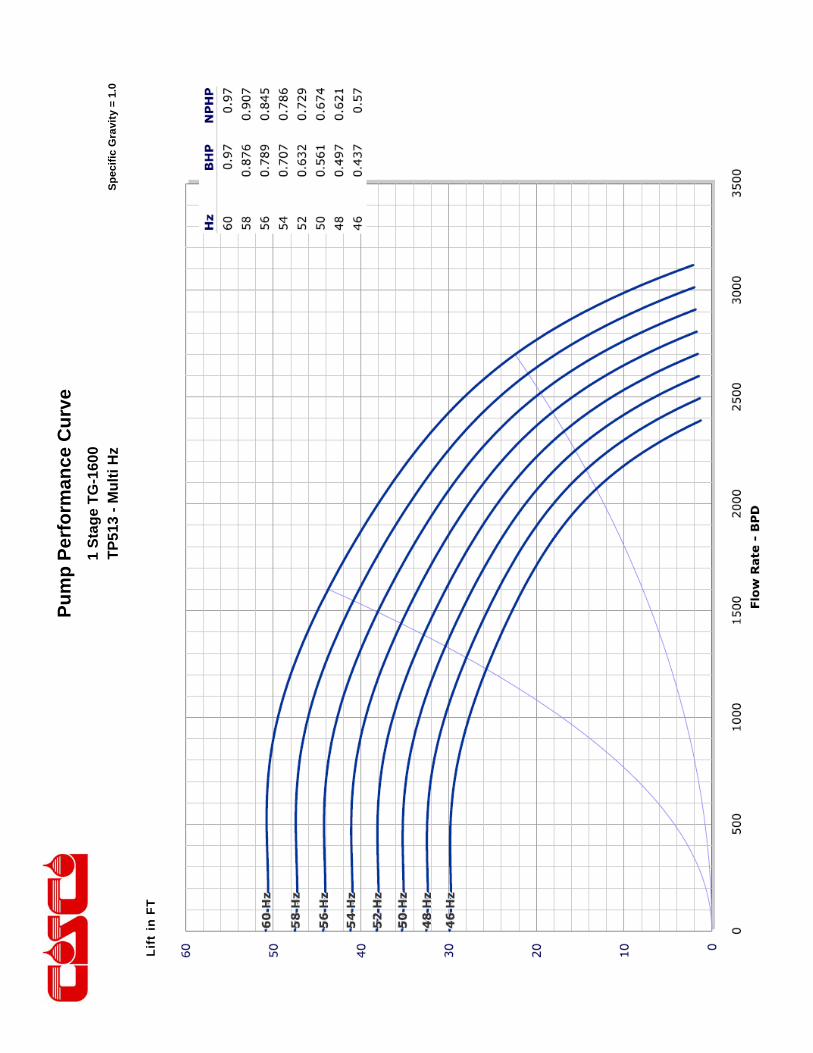
Pu
mp
Per
form
ance
Cu
rve
Sp
ecif
ic G
ravi
ty =
1.0
1 S
tag
e T
G-1
600
TP
513
- M
ult
i Hz
Lift
in F
T

This engineering performance curve represents nominal performance based on actual mul ‐stage tes ng and cer fica on. All pumps supplied by COSCO will be tested and cer fied to perform within the acceptable limits for head, horsepower, and efficiency as defined in the “API RECOMMENDED PRACTICE(11S2) FOR ELECTRIC SUBMERSIBLE PUMP TESTING.”
COSCO 513 Series Pumps
ENGINEERING DATA
Housing Diameter 5.13 inches Maximum Staging: Shaft
Minimum Casing Size 6 5/8 Inches Shaft Type
Fluid Specific Gravity for Pump Curves 1.0 50 Hz 60 Hz
Rotational Direction CCW Standard Shaft 375 261
Shaft Details HSS 601 418
Shaft Diameter 7/8 0.875 Inches Housing Pressure Limit 5000 PSI
Shaft Area 0.6013 Sq. Inches Maximum Staging: Thrust Bearings (250F BHT)
Shaft Limits Bearing Type
No of Stages @
Shaft Limit in HP at: 50 Hz 60 Hz 50 Hz 60 Hz
Standard Shaft Limit 213 256 Standard Bearing 217 180
High Strength (HSS) 342 410 Hi Load Bearing 1200 900
No of Stages @
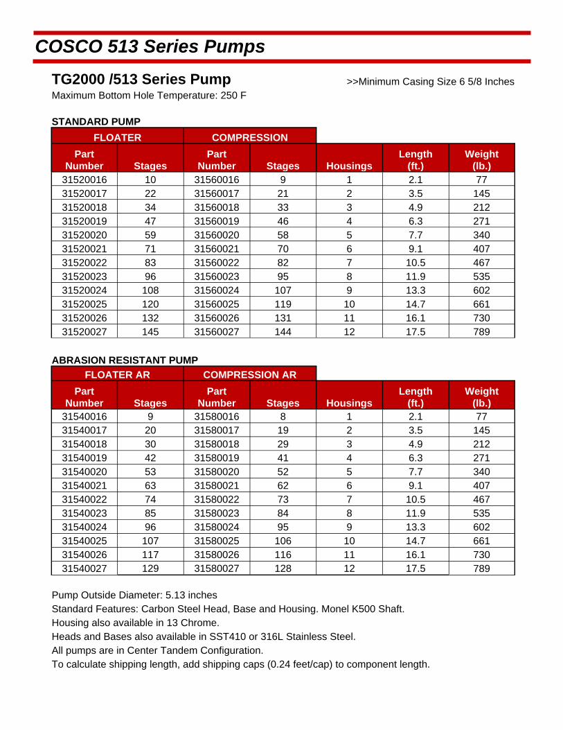
COSCO 513 Series Pumps
TG2000 /513 Series Pump >>Minimum Casing Size 6 5/8 Inches Maximum Bottom Hole Temperature: 250 F
STANDARD PUMP
FLOATER COMPRESSION
Part Number Stages
Part Number Stages Housings
Length (ft.)
Weight (lb.)
31520016 10 31560016 9 1 2.1 77 31520017 22 31560017 21 2 3.5 145 31520018 34 31560018 33 3 4.9 212 31520019 47 31560019 46 4 6.3 271 31520020 59 31560020 58 5 7.7 340 31520021 71 31560021 70 6 9.1 407 31520022 83 31560022 82 7 10.5 467 31520023 96 31560023 95 8 11.9 535 31520024 108 31560024 107 9 13.3 602 31520025 120 31560025 119 10 14.7 661 31520026 132 31560026 131 11 16.1 730 31520027 145 31560027 144 12 17.5 789
ABRASION RESISTANT PUMP
FLOATER AR COMPRESSION AR
Part Number Stages
Part Number Stages Housings
Length (ft.)
Weight (lb.)
31540016 9 31580016 8 1 2.1 77 31540017 20 31580017 19 2 3.5 145 31540018 30 31580018 29 3 4.9 212 31540019 42 31580019 41 4 6.3 271 31540020 53 31580020 52 5 7.7 340 31540021 63 31580021 62 6 9.1 407 31540022 74 31580022 73 7 10.5 467 31540023 85 31580023 84 8 11.9 535 31540024 96 31580024 95 9 13.3 602 31540025 107 31580025 106 10 14.7 661 31540026 117 31580026 116 11 16.1 730 31540027 129 31580027 128 12 17.5 789
Pump Outside Diameter: 5.13 inches Standard Features: Carbon Steel Head, Base and Housing. Monel K500 Shaft. Housing also available in 13 Chrome.
Heads and Bases also available in SST410 or 316L Stainless Steel.
All pumps are in Center Tandem Configuration. To calculate shipping length, add shipping caps (0.24 feet/cap) to component length.
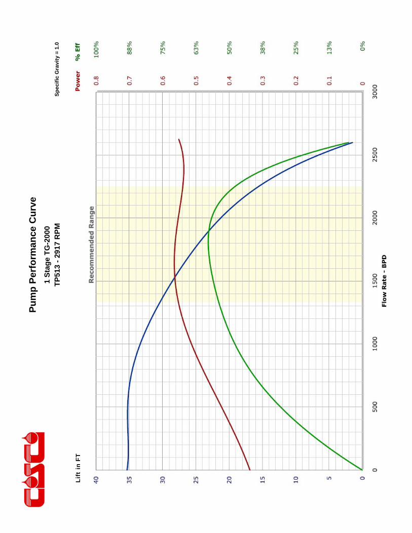
Pu
mp
Per
form
ance
Cu
rve
Sp
ecif
ic G
ravi
ty =
1.0
1 S
tag
e T
G-2
000
TP
513
- 29
17 R
PM
Lift
in F
T

Pu
mp
Per
form
ance
Cu
rve
Sp
ecif
ic G
ravi
ty =
1.0
1 S
tag
e T
G-2
000
TP
513
- M
ult
i Hz
Lift
in F
T

This engineering performance curve represents nominal performance based on actual mul ‐stage tes ng and cer fica on. All pumps supplied by COSCO will be tested and cer fied to perform within the acceptable limits for head, horsepower, and efficiency as defined in the “API RECOMMENDED PRACTICE(11S2) FOR ELECTRIC SUBMERSIBLE PUMP TESTING.”
COSCO 513 Series Pumps
ENGINEERING DATA
Housing Diameter 5.13 inches Maximum Staging: Shaft
Minimum Casing Size 6 5/8 Inches Shaft Type
Fluid Specific Gravity for Pump Curves 1.0 50 Hz 60 Hz
Rotational Direction CCW Standard Shaft 300 210
Shaft Details HSS 480 336
Shaft Diameter 7/8 0.875 Inches Housing Pressure Limit 5000 PSI
Shaft Area 0.6013 Sq. Inches Maximum Staging: Thrust Bearings (250F BHT)
Shaft Limits Bearing Type
No of Stages @
Shaft Limit in HP at: 50 Hz 60 Hz 50 Hz 60 Hz
Standard Shaft Limit 213 256 Standard Bearing 206 171
High Strength (HSS) 342 410 Hi Load Bearing 1139 855
No of Stages @

COSCO 513 Series Pumps
TG2500 /513 Series Pump >>Minimum Casing Size 6 5/8 Inches Maximum Bottom Hole Temperature: 250 F
STANDARD PUMP
FLOATER COMPRESSION
Part Number Stages
Part Number Stages Housings
Length (ft.)
Weight (lb.)
31520031 10 31560031 9 1 2.1 44 31520032 22 31560032 21 2 3.5 73 31520033 34 31560033 33 3 4.8 106 31520034 47 31560034 46 4 6.3 134 31520035 59 31560035 58 5 7.8 165 31520036 71 31560036 70 6 9.2 196 31520037 83 31560037 82 7 10.6 225 31520038 96 31560038 95 8 12 258 31520039 108 31560039 107 9 13.4 287 31520040 120 31560040 119 10 14.8 317 31520041 132 31560041 131 11 16.2 348 31520042 145 31560042 144 12 17.6 377
ABRASION RESISTANT PUMP
FLOATER AR COMPRESSION AR
Part Number Stages
Part Number Stages Housings
Length (ft.)
Weight (lb.)
31540031 9 31580031 8 1 2.1 44 31540032 20 31580032 19 2 3.5 73 31540033 30 31580033 29 3 4.8 106 31540034 42 31580034 41 4 6.3 134 31540035 53 31580035 52 5 7.8 165 31540036 63 31580036 62 6 9.2 196 31540037 74 31580037 73 7 10.6 225 31540038 85 31580038 84 8 12 258 31540039 96 31580039 95 9 13.4 287 31540040 107 31580040 106 10 14.8 317 31540041 117 31580041 116 11 16.2 348 31540042 129 31580042 128 12 17.6 377
Pump Outside Diameter: 5.13 inches Standard Features: Carbon Steel Head, Base and Housing. Monel K500 Shaft. Housing also available in 13 Chrome.
Heads and Bases also available in SST410 or 316L Stainless Steel.
All pumps are in Center Tandem Configuration. To calculate shipping length, add shipping caps (0.24 feet/cap) to component length.
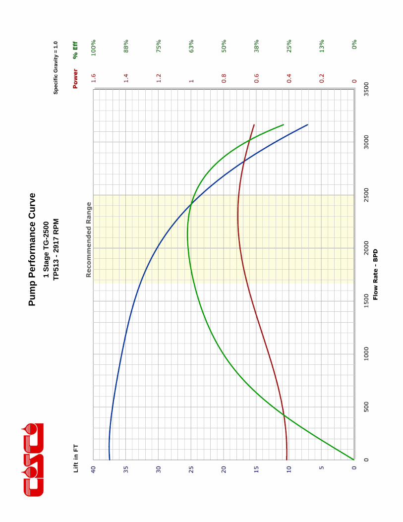
Pu
mp
Per
form
ance
Cu
rve
Sp
ecif
ic G
ravi
ty =
1.0
1 S
tag
e T
G-2
500
TP
513
- 29
17 R
PM
Lift
in F
T

Pu
mp
Per
form
ance
Cu
rve
Sp
ecif
ic G
ravi
ty =
1.0
1 S
tag
e T
G-2
500
TP
513
- M
ult
i Hz
Lift
in F
T
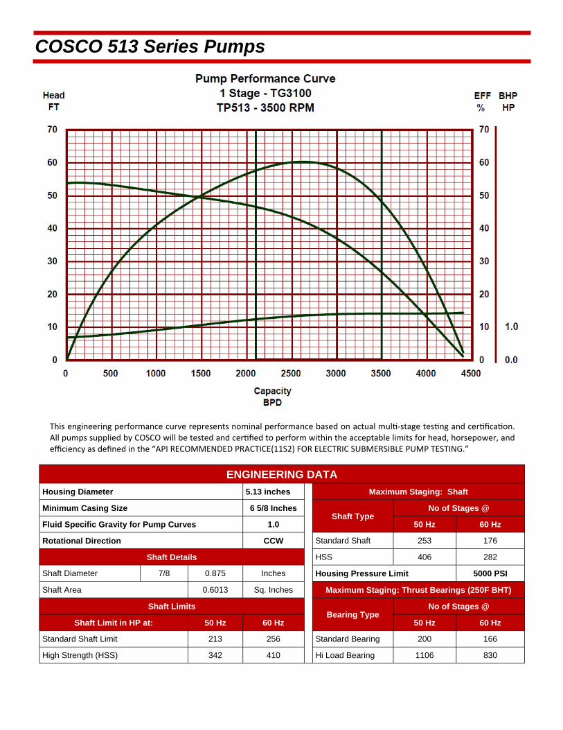
This engineering performance curve represents nominal performance based on actual mul ‐stage tes ng and cer fica on. All pumps supplied by COSCO will be tested and cer fied to perform within the acceptable limits for head, horsepower, and efficiency as defined in the “API RECOMMENDED PRACTICE(11S2) FOR ELECTRIC SUBMERSIBLE PUMP TESTING.”
COSCO 513 Series Pumps
ENGINEERING DATA
Housing Diameter 5.13 inches Maximum Staging: Shaft
Minimum Casing Size 6 5/8 Inches Shaft Type
Fluid Specific Gravity for Pump Curves 1.0 50 Hz 60 Hz
Rotational Direction CCW Standard Shaft 253 176
Shaft Details HSS 406 282
Shaft Diameter 7/8 0.875 Inches Housing Pressure Limit 5000 PSI
Shaft Area 0.6013 Sq. Inches Maximum Staging: Thrust Bearings (250F BHT)
Shaft Limits Bearing Type
No of Stages @
Shaft Limit in HP at: 50 Hz 60 Hz 50 Hz 60 Hz
Standard Shaft Limit 213 256 Standard Bearing 200 166
High Strength (HSS) 342 410 Hi Load Bearing 1106 830
No of Stages @

COSCO 513 Series Pumps
TG3100 /513 Series Pump >>Minimum Casing Size 6 5/8 Inches Maximum Bottom Hole Temperature: 250 F
STANDARD PUMP
FLOATER COMPRESSION
Part Number Stages
Part Number Stages Housings
Length (ft.)
Weight (lb.)
31520046 10 31560046 9 1 2.1 77 31520047 22 31560047 21 2 3.5 145 31520048 34 31560048 33 3 4.9 212 31520049 47 31560049 46 4 6.3 271 31520050 59 31560050 58 5 7.7 340 31520051 71 31560051 70 6 9.1 407 31520052 83 31560052 82 7 10.5 467 31520053 96 31560053 95 8 11.9 535 31520054 108 31560054 107 9 13.3 602 31520055 120 31560055 119 10 14.7 661 31520056 132 31560056 131 11 16.1 730 31520057 145 31560057 144 12 17.5 789
ABRASION RESISTANT PUMP
FLOATER AR COMPRESSION AR
Part Number Stages
Part Number Stages Housings
Length (ft.)
Weight (lb.)
31540046 9 31580046 8 1 2.1 77 31540047 20 31580047 19 2 3.5 145 31540048 30 31580048 29 3 4.9 212 31540049 42 31580049 41 4 6.3 271 31540050 53 31580050 52 5 7.7 340 31540051 63 31580051 62 6 9.1 407 31540052 74 31580052 73 7 10.5 467 31540053 85 31580053 84 8 11.9 535 31540054 96 31580054 95 9 13.3 602 31540055 107 31580055 106 10 14.7 661 31540056 117 31580056 116 11 16.1 730 31540057 129 31580057 128 12 17.5 789
Pump Outside Diameter: 5.13 inches Standard Features: Carbon Steel Head, Base and Housing. Monel K500 Shaft. Housing also available in 13 Chrome.
Heads and Bases also available in SST410 or 316L Stainless Steel.
All pumps are in Center Tandem Configuration. To calculate shipping length, add shipping caps (0.24 feet/cap) to component length.
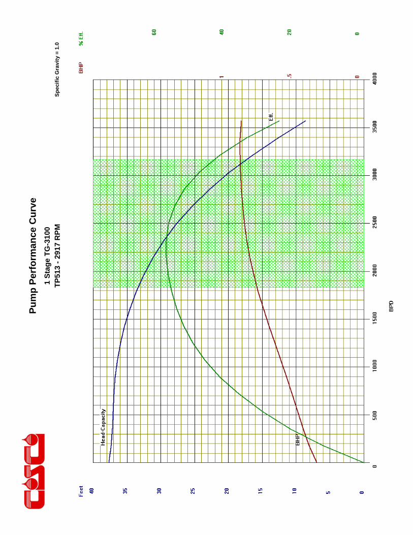
Pu
mp
Per
form
ance
Cu
rve
Sp
ecif
ic G
ravi
ty =
1.0
1 S
tag
e T
G-3
100
TP
513
- 29
17 R
PM
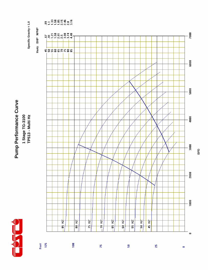
Pu
mp
Per
form
ance
Cu
rve
Sp
ecif
ic G
ravi
ty =
1.0
1 S
tag
e T
G-3
100
TP
513
- M
ult
i Hz

This engineering performance curve represents nominal performance based on actual mul ‐stage tes ng and cer fica on. All pumps supplied by COSCO will be tested and cer fied to perform within the acceptable limits for head, horsepower, and efficiency as defined in the “API RECOMMENDED PRACTICE(11S2) FOR ELECTRIC SUBMERSIBLE PUMP TESTING.”
COSCO 513 Series Pumps
ENGINEERING DATA
Housing Diameter 5.13 inches Maximum Staging: Shaft
Minimum Casing Size 6 5/8 Inches Shaft Type
Fluid Specific Gravity for Pump Curves 1.0 50 Hz 60 Hz
Rotational Direction CCW Standard Shaft 336 234
Shaft Details HSS 540 375
Shaft Diameter 1 1.000 Inches Housing Pressure Limit 5000 PSI
Shaft Area 0.7854 Sq. Inches Maximum Staging: Thrust Bearings (250F BHT)
Shaft Limits Bearing Type
No of Stages @
Shaft Limit in HP at: 50 Hz 60 Hz 50 Hz 60 Hz
Standard Shaft Limit 312 375 Standard Bearing 156 130
High Strength (HSS) 500 600 Hi Load Bearing 862 650
No of Stages @
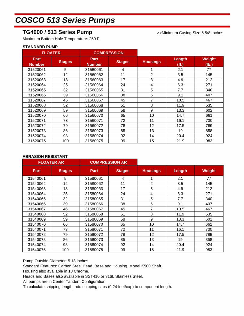
COSCO 513 Series Pumps
TG4000 / 513 Series Pump >>Minimum Casing Size 6 5/8 Inches
Maximum Bottom Hole Temperature: 250 F
STANDARD PUMP
FLOATER COMPRESSION
Part Number
Stages Part
Number Stages Housings
Length (ft.)
Weight (lb.)
31520061 5 31560061 4 1 2.1 77 31520062 12 31560062 11 2 3.5 145 31520063 18 31560063 17 3 4.9 212 31520064 25 31560064 24 4 6.3 271 31520065 32 31560065 31 5 7.7 340 31520066 39 31560066 38 6 9.1 407 31520067 46 31560067 45 7 10.5 467 31520068 52 31560068 51 8 11.9 535 31520069 59 31560069 58 9 13.3 602 31520070 66 31560070 65 10 14.7 661 31520071 73 31560071 72 11 16.1 730 31520072 79 31560072 78 12 17.5 789 31520073 86 31560073 85 13 19 858 31520074 93 31560074 92 14 20.4 924 31520075 100 31560075 99 15 21.9 983
ABRASION RESISTANT
FLOATER AR COMPRESSION AR
Part Stages Part Stages Housings Length Weight
31540061 5 31580061 4 1 2.1 77 31540062 12 31580062 11 2 3.5 145 31540063 18 31580063 17 3 4.9 212 31540064 25 31580064 24 4 6.3 271 31540065 32 31580065 31 5 7.7 340 31540066 39 31580066 38 6 9.1 407 31540067 46 31580067 45 7 10.5 467 31540068 52 31580068 51 8 11.9 535 31540069 59 31580069 58 9 13.3 602 31540070 66 31580070 65 10 14.7 661 31540071 73 31580071 72 11 16.1 730 31540072 79 31580072 78 12 17.5 789 31540073 86 31580073 85 13 19 858 31540074 93 31580074 92 14 20.4 924 31540075 100 31580075 99 15 21.9 983
Pump Outside Diameter: 5.13 inches Standard Features: Carbon Steel Head, Base and Housing. Monel K500 Shaft. Housing also available in 13 Chrome.
Heads and Bases also available in SST410 or 316L Stainless Steel.
All pumps are in Center Tandem Configuration. To calculate shipping length, add shipping caps (0.24 feet/cap) to component length.

Pu
mp
Per
form
ance
Cu
rve
Sp
ecif
ic G
ravi
ty =
1.0
1 S
tag
e T
G-4
000
TP
513
- 29
17 R
PM
Lift
in F
T

Pu
mp
Per
form
ance
Cu
rve
Sp
ecif
ic G
ravi
ty =
1.0
1 S
tag
e T
G-4
000
TP
513
- M
ult
i Hz
Lift
in F
T

This engineering performance curve represents nominal performance based on actual mul ‐stage tes ng and cer fica on. All pumps supplied by COSCO will be tested and cer fied to perform within the acceptable limits for head, horsepower, and efficiency as defined in the “API RECOMMENDED PRACTICE(11S2) FOR ELECTRIC SUBMERSIBLE PUMP TESTING.”
COSCO 513 Series Pumps
ENGINEERING DATA
Housing Diameter 5.13 inches Maximum Staging: Shaft
Minimum Casing Size 6 5/8 Inches Shaft Type
Fluid Specific Gravity for Pump Curves 1.0 50 Hz 60 Hz
Rotational Direction CCW Standard Shaft 298 207
Shaft Details HSS 476 331
Shaft Diameter 1 1.000 Inches Housing Pressure Limit 5000 PSI
Shaft Area 0.7854 Sq. Inches Maximum Staging: Thrust Bearings (250F BHT)
Shaft Limits Bearing Type
No of Stages @
Shaft Limit in HP at: 50 Hz 60 Hz 50 Hz 60 Hz
Standard Shaft Limit 312 375 Standard Bearing 191 159
High Strength (HSS) 500 600 Hi Load Bearing 1056 795
No of Stages @

COSCO 513 Series Pumps
TG5600 / 513 Series Pump >>Minimum Casing Size 6 5/8 Inches
Maximum Bottom Hole Temperature: 250 F
STANDARD PUMP
FLOATER COMPRESSION
Part Stages Part Stages Housings Length Weight
31520076 3 31560076 2 1 2.1 77 31520077 8 31560077 7 2 3.5 145 31520078 13 31560078 12 3 4.9 212 31520079 17 31560079 16 4 6.3 271 31520080 22 31560080 21 5 7.7 340 31520081 27 31560081 26 6 9.1 407 31520082 31 31560082 30 7 10.5 467 31520083 36 31560083 35 8 11.9 535 31520084 41 31560084 40 9 13.3 602 31520085 45 31560085 44 10 14.7 661 31520086 50 31560086 49 11 16.1 730 31520087 54 31560087 53 12 17.5 789 31520088 59 31560088 58 13 19 858 31520089 64 31560089 63 14 20.4 924 31520090 68 31560090 67 15 21.9 983
ABRASION RESISTANT
FLOATER AR COMPRESSION AR
Part Stages Part Stages Housings Length Weight
31540076 3 31580076 2 1 2.1 77 31540077 8 31580077 7 2 3.5 145 31540078 13 31580078 12 3 4.9 212 31540079 17 31580079 16 4 6.3 271 31540080 22 31580080 21 5 7.7 340 31540081 27 31580081 26 6 9.1 407 31540082 31 31580082 30 7 10.5 467 31540083 36 31580083 35 8 11.9 535 31540084 41 31580084 40 9 13.3 602 31540085 45 31580085 44 10 14.7 661 31540086 50 31580086 49 11 16.1 730 31540087 54 31580087 53 12 17.5 789 31540088 59 31580088 58 13 19 858 31540089 64 31580089 63 14 20.4 924 31540090 68 31580090 67 15 21.9 983
Pump Outside Diameter: 5.13 inches Standard Features: Carbon Steel Head, Base and Housing. Monel K500 Shaft. Housing also available in 13 Chrome.
Heads and Bases also available in SST410 or 316L Stainless Steel.
All pumps are in Center Tandem Configuration. To calculate shipping length, add shipping caps (0.24 feet/cap) to component length.

Pu
mp
Per
form
ance
Cu
rve
Sp
ecif
ic G
ravi
ty =
1.0
1 S
tag
e T
G-5
600
TP
513
- 29
17 R
PM
Lift
in F
T

Pu
mp
Per
form
ance
Cu
rve
Sp
ecif
ic G
ravi
ty =
1.0
1 S
tag
e T
G-5
600
TP
513
- M
ult
i Hz
Lift
in F
T

This engineering performance curve represents nominal performance based on actual mul ‐stage tes ng and cer fica on. All pumps supplied by COSCO will be tested and cer fied to perform within the acceptable limits for head, horsepower, and efficiency as defined in the “API RECOMMENDED PRACTICE(11S2) FOR ELECTRIC SUBMERSIBLE PUMP TESTING.”
COSCO 513 Series Pumps
ENGINEERING DATA
Housing Diameter 5.13 inches Maximum Staging: Shaft
Minimum Casing Size 6 5/8 Inches Shaft Type
Fluid Specific Gravity for Pump Curves 1.0 50 Hz 60 Hz
Rotational Direction CCW Standard Shaft 214 149
Shaft Details HSS 344 239
Shaft Diameter 1 1.000 Inches Housing Pressure Limit 5000 PSI
Shaft Area 0.7854 Sq. Inches Maximum Staging: Thrust Bearings (250F BHT)
Shaft Limits Bearing Type
No of Stages @
Shaft Limit in HP at: 50 Hz 60 Hz 50 Hz 60 Hz
Standard Shaft Limit 312 375 Standard Bearing 179 149
High Strength (HSS) 500 600 Hi Load Bearing 989 745
No of Stages @

COSCO 513 Series Pumps
TG7000 / 513 Series Pump >>Minimum Casing Size 6 5/8 Inches
Maximum Bottom Hole Temperature: 250 F
STANDARD PUMP
FLOATER COMPRESSION
Part Stages Part Stages Housings Length Weight
31520091 3 31560091 2 1 2.1 77 31520092 8 31560092 7 2 3.5 145 31520093 13 31560093 12 3 4.9 212 31520094 17 31560094 16 4 6.3 271 31520095 22 31560095 21 5 7.7 340 31520096 27 31560096 26 6 9.1 407 31520097 31 31560097 30 7 10.5 467 31520098 36 31560098 35 8 11.9 535 31520099 41 31560099 40 9 13.3 602 31520100 45 31560100 44 10 14.7 661 31520101 50 31560101 49 11 16.1 730 31520102 54 31560102 53 12 17.5 789 31520103 59 31560103 58 13 19 858 31520104 64 31560104 63 14 20.4 924 31520105 68 31560105 67 15 21.9 983
ABRASION RESISTANT PUMP
FLOATER AR COMPRESSION AR
Part Number
Stages Part
Number Stages Housings
Length (ft.)
Weight (lb.)
31540091 3 31580091 2 1 2.1 77 31540092 8 31580092 7 2 3.5 145 31540093 13 31580093 12 3 4.9 212 31540094 17 31580094 16 4 6.3 271 31540095 22 31580095 21 5 7.7 340 31540096 27 31580096 26 6 9.1 407 31540097 31 31580097 30 7 10.5 467 31540098 36 31580098 35 8 11.9 535 31540099 41 31580099 40 9 13.3 602 31540100 45 31580100 44 10 14.7 661 31540101 50 31580101 49 11 16.1 730 31540102 54 31580102 53 12 17.5 789 31540103 59 31580103 58 13 19 858 31540104 64 31580104 63 14 20.4 924 31540105 68 31580105 67 15 21.9 983
Pump Outside Diameter: 5.13 inches Standard Features: Carbon Steel Head, Base and Housing. Monel K500 Shaft. Housing also available in 13 Chrome.
Heads and Bases also available in SST410 or 316L Stainless Steel.
All pumps are in Center Tandem Configuration. To calculate shipping length, add shipping caps (0.24 feet/cap) to component length.

Pu
mp
Per
form
ance
Cu
rve
Sp
ecif
ic G
ravi
ty =
1.0
1 S
tag
e T
G-7
000
TP
513
- 29
17 R
PM
Lift
in F
T
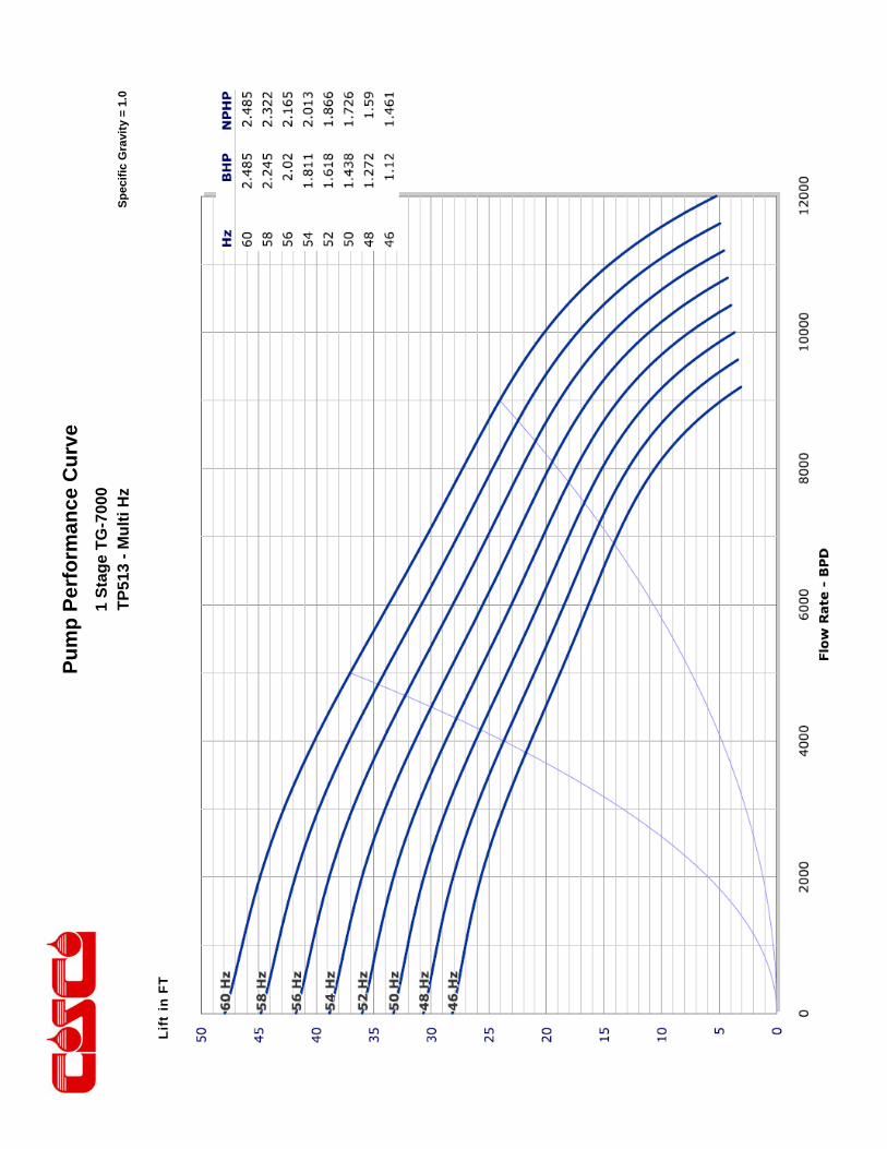
Pu
mp
Per
form
ance
Cu
rve
Sp
ecif
ic G
ravi
ty =
1.0
1 S
tag
e T
G-7
000
TP
513
- M
ult
i Hz
Lift
in F
T
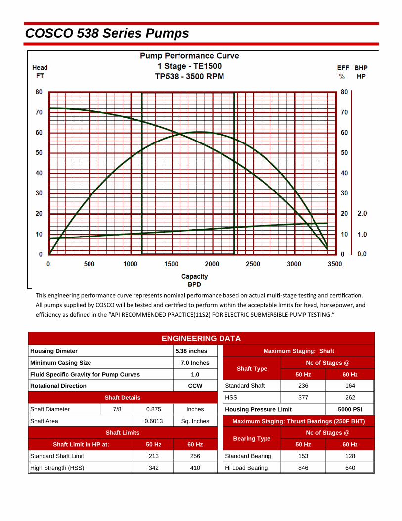
This engineering performance curve represents nominal performance based on actual mul ‐stage tes ng and cer fica on.
All pumps supplied by COSCO will be tested and cer fied to perform within the acceptable limits for head, horsepower, and
efficiency as defined in the “API RECOMMENDED PRACTICE(11S2) FOR ELECTRIC SUBMERSIBLE PUMP TESTING.”
COSCO 538 Series Pumps
ENGINEERING DATA
Housing Dimeter 5.38 inches Maximum Staging: Shaft
Minimum Casing Size 7.0 Inches Shaft Type
Fluid Specific Gravity for Pump Curves 1.0 50 Hz 60 Hz
Rotational Direction CCW Standard Shaft 236 164
Shaft Details HSS 377 262
Shaft Diameter 7/8 0.875 Inches Housing Pressure Limit 5000 PSI
Shaft Area 0.6013 Sq. Inches Maximum Staging: Thrust Bearings (250F BHT)
Shaft Limits Bearing Type
No of Stages @
Shaft Limit in HP at: 50 Hz 60 Hz 50 Hz 60 Hz
Standard Shaft Limit 213 256 Standard Bearing 153 128
High Strength (HSS) 342 410 Hi Load Bearing 846 640
No of Stages @

COSCO 538 Series Pumps
TE1500 / 538 Series Pump >>Minimum Casing Size 7 Inches
Maximum Bottom Hole Temperature: 250 F
STANDARD PUMP
FLOATER COMPRESSION
Part Number
Stages Part
Number Stages Housings
Length (ft.)
Weight (lb.)
31520106 7 31560106 6 1 2.5 93 31520107 14 31560107 13 2 4 157 31520108 22 31560108 21 3 5.5 220 31520109 30 31560109 29 4 7 284 31520110 37 31560110 36 5 8.5 347 31520111 45 31560111 44 6 10 412 31520112 52 31560112 51 7 11.5 473 31520113 60 31560113 59 8 13 537 31520114 68 31560114 67 9 14.5 602 31520115 75 31560115 74 10 16 665 31520116 83 31560116 82 11 17.5 729 31520117 90 31560117 89 12 19 793 31520118 98 31560118 97 13 20.5 857 31520119 106 31560119 105 14 22 921 31520120 113 31560120 112 15 23.5 985
ABRASION RESISTANT PUMP
FLOATER AR COMPRESSION AR
Part Number
Stages Part
Number Stages Housings
Length (ft.)
Weight (lb.)
31540106 7 31580106 6 1 2.5 93 31540107 14 31580107 13 2 4 157 31540108 22 31580108 21 3 5.5 220 31540109 30 31580109 29 4 7 284 31540110 37 31580110 36 5 8.5 347 31540111 45 31580111 44 6 10 412 31540112 52 31580112 51 7 11.5 473 31540113 60 31580113 59 8 13 537 31540114 68 31580114 67 9 14.5 602 31540115 75 31580115 74 10 16 665 31540116 83 31580116 82 11 17.5 729 31540117 90 31580117 89 12 19 793 31540118 98 31580118 97 13 20.5 857 31540119 106 31580119 105 14 22 921 31540120 113 31580120 112 15 23.5 985
Pump Outside Diameter: 5.38 inches Standard Features: Carbon Steel Head, Base and Housing. Monel K500 Shaft. Housing also available in 13 Chrome.
Heads and Bases also available in SST410 or 316L Stainless Steel.
All pumps are in Center Tandem Configuration. To calculate shipping Length, add shipping caps (0.24 feet/cap) to component Length.
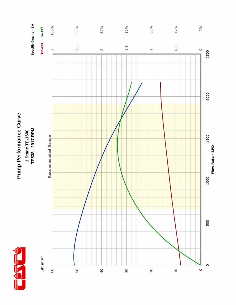
Pu
mp
Per
form
ance
Cu
rve
Sp
ecif
ic G
ravi
ty =
1.0
1 S
tag
e T
E-1
500
TP
538
- 29
17 R
PM
Lift
in F
T
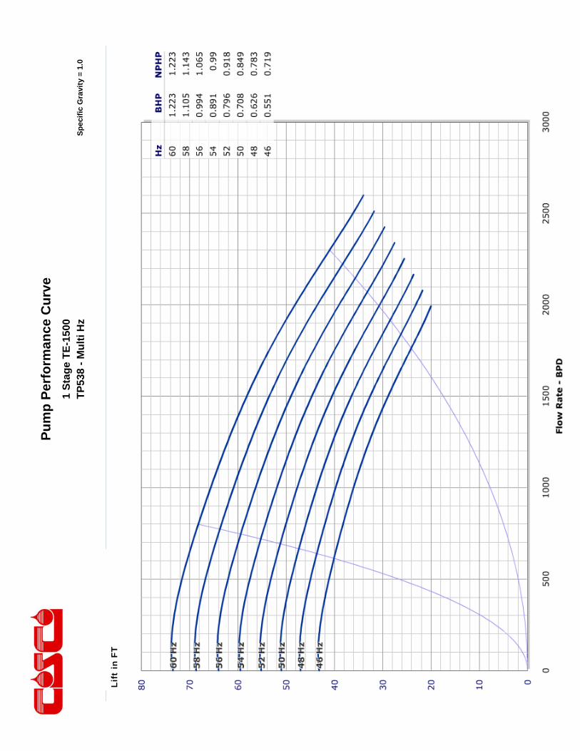
Pu
mp
Per
form
ance
Cu
rve
Sp
ecif
ic G
ravi
ty =
1.0
1 S
tag
e T
E-1
500
TP
538
- M
ult
i Hz
Li
ft in
FT
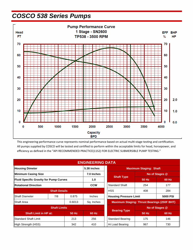
This engineering performance curve represents nominal performance based on actual mul ‐stage tes ng and cer fica on.
All pumps supplied by COSCO will be tested and cer fied to perform within the acceptable limits for head, horsepower, and
efficiency as defined in the “API RECOMMENDED PRACTICE(11S2) FOR ELECTRIC SUBMERSIBLE PUMP TESTING.”
COSCO 538 Series Pumps
ENGINEERING DATA
Housing Dimeter 5.38 inches Maximum Staging: Shaft
Minimum Casing Size 7.0 Inches Shaft Type
Fluid Specific Gravity for Pump Curves 1.0 50 Hz 60 Hz
Rotational Direction CCW Standard Shaft 254 177
Shaft Details HSS 408 284
Shaft Diameter 7/8 0.875 Inches Housing Pressure Limit 5000 PSI
Shaft Area 0.6013 Sq. Inches Maximum Staging: Thrust Bearings (250F BHT)
Shaft Limits Bearing Type
No of Stages @
Shaft Limit in HP at: 50 Hz 60 Hz 50 Hz 60 Hz
Standard Shaft Limit 213 256 Standard Bearing 175 146
High Strength (HSS) 342 410 Hi Load Bearing 967 730
No of Stages @

COSCO 538 Series Pumps
SN2600 / 538 Series Pump >>Minimum Casing Size 7 Inches
Maximum Bottom Hole Temperature: 250 F
STANDARD PUMP
FLOATER COMPRESSION
Part Number
Stages Part
Number Stages Housings
Length (ft.)
Weight (lb.)
31520121 13 31560121 12 1 2.5 93 31520122 27 31560122 26 2 4 157 31520123 41 31560123 40 3 5.5 220 31520124 55 31560124 54 4 7 284 31520125 69 31560125 68 5 8.5 347 31520126 83 31560126 82 6 10 412 31520127 97 31560127 96 7 11.5 473 31520128 111 31560128 110 8 13 537 31520129 125 31560129 124 9 14.5 602 31520130 139 31560130 138 10 16 665 31520131 153 31560131 152 11 17.5 729 31520132 166 31560132 165 12 19 793 31520133 180 31560133 179 13 20.5 857 31520134 194 31560134 193 14 22 921 31520135 208 31560135 207 15 23.5 985
ABRASION RESISTANT PUMP
FLOATER AR COMPRESSION AR
Part Number
Stages Part
Number Stages Housings
Length (ft.)
Weight (lb.)
31540121 12 31580121 11 1 2.5 93 31540122 24 31580122 23 2 4 157 31540123 37 31580123 36 3 5.5 220 31540124 49 31580124 48 4 7 284 31540125 62 31580125 61 5 8.5 347 31540126 74 31580126 73 6 10 412 31540127 87 31580127 86 7 11.5 473 31540128 99 31580128 98 8 13 537 31540129 112 31580129 111 9 14.5 602 31540130 124 31580130 123 10 16 665 31540131 136 31580131 135 11 17.5 729 31540132 148 31580132 147 12 19 793 31540133 160 31580133 159 13 20.5 857 31540134 173 31580134 172 14 22 921 31540135 185 31580135 184 15 23.5 985
Pump Outside Diameter: 5.38 inches Standard Features: Carbon Steel Head, Base and Housing. Monel K500 Shaft. Housing also available in 13 Chrome.
Heads and Bases also available in SST410 or 316L Stainless Steel.
All pumps are in Center Tandem Configuration. To calculate shipping Length, add shipping caps (0.24 feet/cap) to component Length.
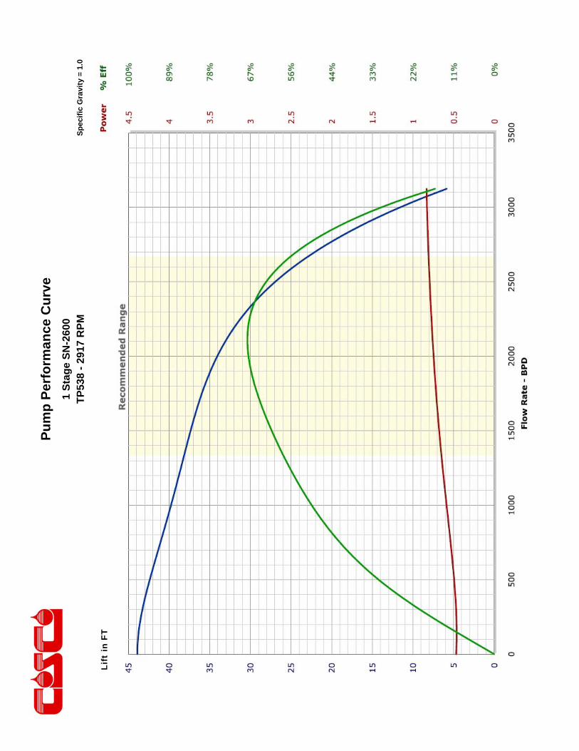
Pu
mp
Per
form
ance
Cu
rve
Sp
ecif
ic G
ravi
ty =
1.0
1 S
tag
e S
N-2
600
TP
538
- 29
17 R
PM
Lift
in F
T
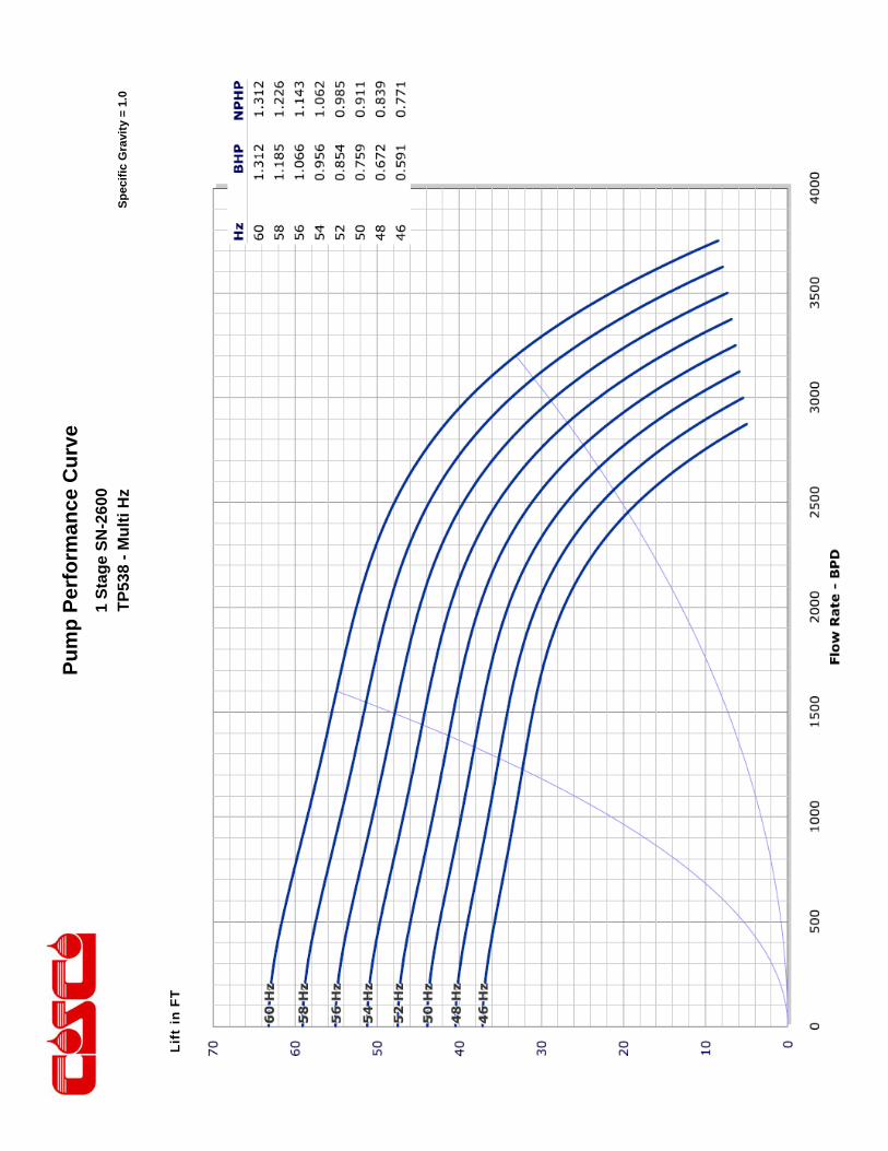
Pu
mp
Per
form
ance
Cu
rve
Sp
ecif
ic G
ravi
ty =
1.0
1 S
tag
e S
N-2
600
TP
538
- M
ult
i Hz
Lift
in F
T

This engineering performance curve represents nominal performance based on actual mul ‐stage tes ng and cer fica on.
All pumps supplied by COSCO will be tested and cer fied to perform within the acceptable limits for head, horsepower, and
efficiency as defined in the “API RECOMMENDED PRACTICE(11S2) FOR ELECTRIC SUBMERSIBLE PUMP TESTING.”
COSCO 538 Series Pumps
ENGINEERING DATA
Housing Dimeter 5.38 inches Maximum Staging: Shaft
Minimum Casing Size 7.0 Inches Shaft Type
Fluid Specific Gravity for Pump Curves 1.0 50 Hz 60 Hz
Rotational Direction CCW Standard Shaft 188 131
Shaft Details HSS 302 210
Shaft Diameter 7/8 0.875 Inches Housing Pressure Limit 5000 PSI
Shaft Area 0.6013 Sq. Inches Maximum Staging: Thrust Bearings (250F BHT)
Shaft Limits Bearing Type
No of Stages @
Shaft Limit in HP at: 50 Hz 60 Hz 50 Hz 60 Hz
Standard Shaft Limit 213 256 Standard Bearing 173 144
High Strength (HSS) 342 410 Hi Load Bearing 956 720
No of Stages @
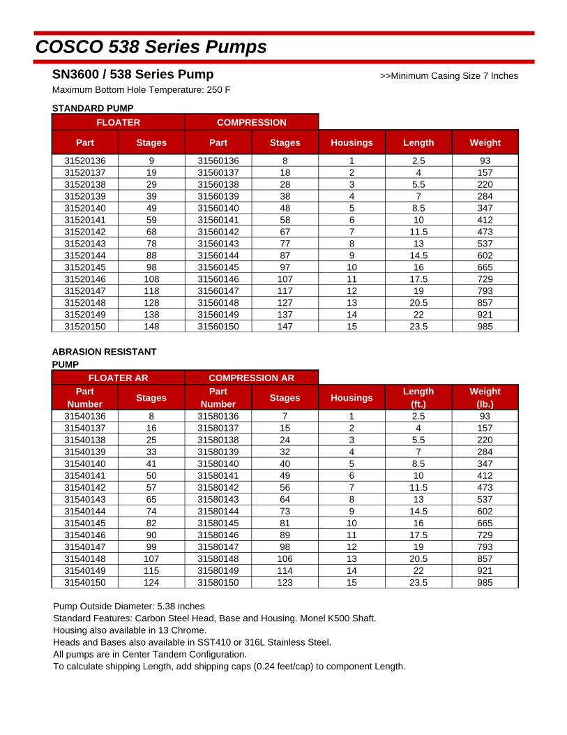
COSCO 538 Series Pumps
SN3600 / 538 Series Pump >>Minimum Casing Size 7 Inches
Maximum Bottom Hole Temperature: 250 F
STANDARD PUMP
FLOATER COMPRESSION
Part Stages Part Stages Housings Length Weight
31520136 9 31560136 8 1 2.5 93 31520137 19 31560137 18 2 4 157 31520138 29 31560138 28 3 5.5 220 31520139 39 31560139 38 4 7 284 31520140 49 31560140 48 5 8.5 347 31520141 59 31560141 58 6 10 412 31520142 68 31560142 67 7 11.5 473 31520143 78 31560143 77 8 13 537 31520144 88 31560144 87 9 14.5 602 31520145 98 31560145 97 10 16 665 31520146 108 31560146 107 11 17.5 729 31520147 118 31560147 117 12 19 793 31520148 128 31560148 127 13 20.5 857 31520149 138 31560149 137 14 22 921 31520150 148 31560150 147 15 23.5 985
ABRASION RESISTANT PUMP
FLOATER AR COMPRESSION AR
Part Number
Stages Part
Number Stages Housings
Length (ft.)
Weight (lb.)
31540136 8 31580136 7 1 2.5 93 31540137 16 31580137 15 2 4 157 31540138 25 31580138 24 3 5.5 220 31540139 33 31580139 32 4 7 284 31540140 41 31580140 40 5 8.5 347 31540141 50 31580141 49 6 10 412 31540142 57 31580142 56 7 11.5 473 31540143 65 31580143 64 8 13 537 31540144 74 31580144 73 9 14.5 602 31540145 82 31580145 81 10 16 665 31540146 90 31580146 89 11 17.5 729 31540147 99 31580147 98 12 19 793 31540148 107 31580148 106 13 20.5 857 31540149 115 31580149 114 14 22 921 31540150 124 31580150 123 15 23.5 985
Pump Outside Diameter: 5.38 inches Standard Features: Carbon Steel Head, Base and Housing. Monel K500 Shaft. Housing also available in 13 Chrome.
Heads and Bases also available in SST410 or 316L Stainless Steel.
All pumps are in Center Tandem Configuration. To calculate shipping Length, add shipping caps (0.24 feet/cap) to component Length.
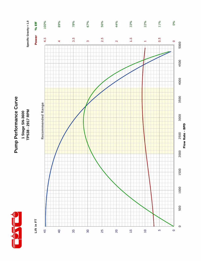
Pu
mp
Per
form
ance
Cu
rve
Sp
ecif
ic G
ravi
ty =
1.0
1 S
tag
e S
N-3
600
TP
538
- 29
17 R
PM
Lift
in F
T
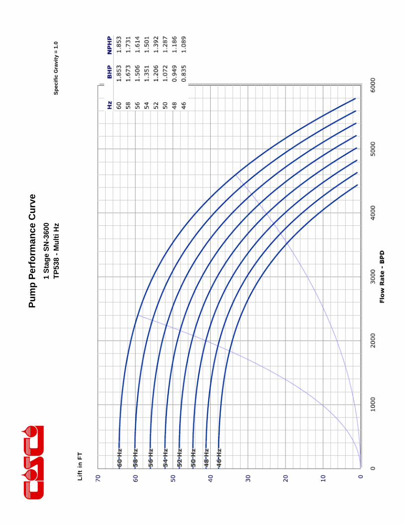
Pu
mp
Per
form
ance
Cu
rve
Sp
ecif
ic G
ravi
ty =
1.0
1 S
tag
e S
N-3
600
TP
538
- M
ult
i Hz
Lift
in F
T
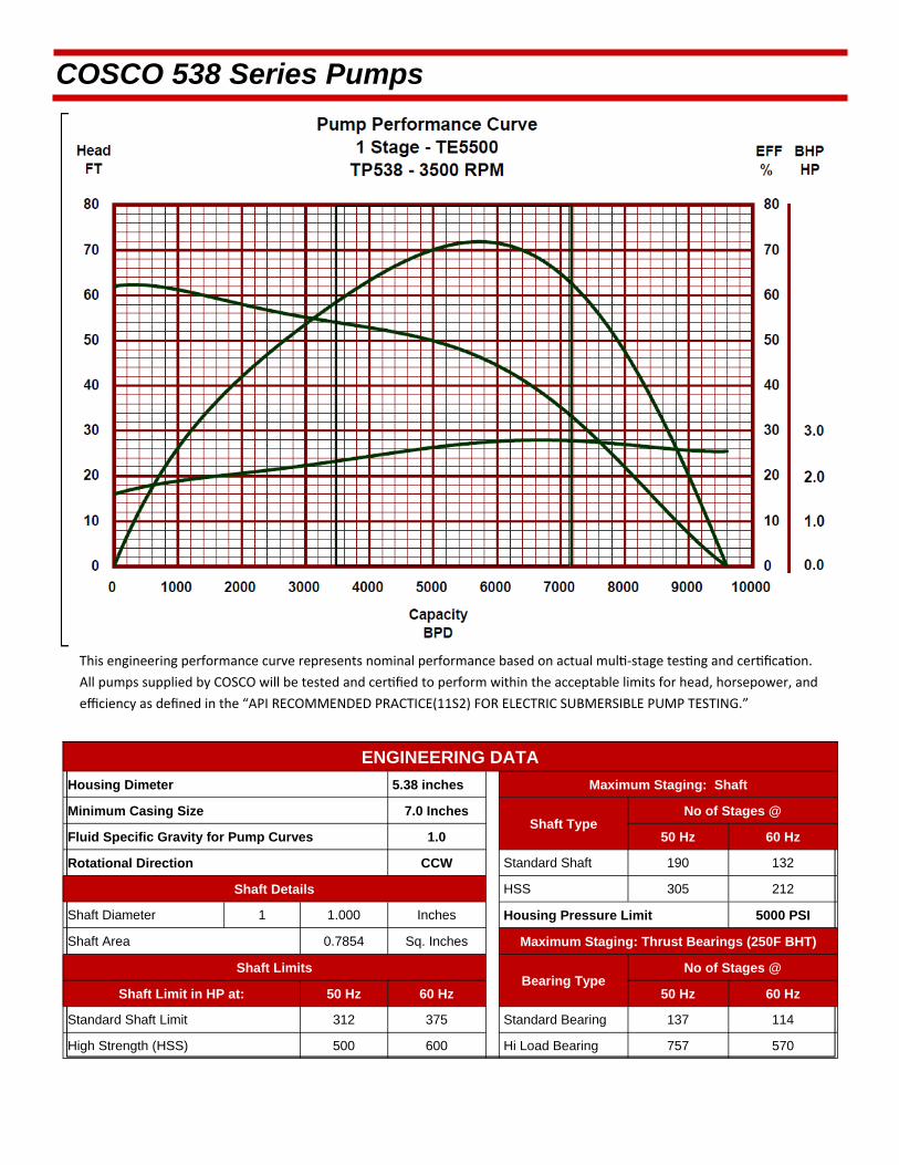
This engineering performance curve represents nominal performance based on actual mul ‐stage tes ng and cer fica on.
All pumps supplied by COSCO will be tested and cer fied to perform within the acceptable limits for head, horsepower, and
efficiency as defined in the “API RECOMMENDED PRACTICE(11S2) FOR ELECTRIC SUBMERSIBLE PUMP TESTING.”
COSCO 538 Series Pumps
ENGINEERING DATA
Housing Dimeter 5.38 inches Maximum Staging: Shaft
Minimum Casing Size 7.0 Inches Shaft Type
Fluid Specific Gravity for Pump Curves 1.0 50 Hz 60 Hz
Rotational Direction CCW Standard Shaft 190 132
Shaft Details HSS 305 212
Shaft Diameter 1 1.000 Inches Housing Pressure Limit 5000 PSI
Shaft Area 0.7854 Sq. Inches Maximum Staging: Thrust Bearings (250F BHT)
Shaft Limits Bearing Type
No of Stages @
Shaft Limit in HP at: 50 Hz 60 Hz 50 Hz 60 Hz
Standard Shaft Limit 312 375 Standard Bearing 137 114
High Strength (HSS) 500 600 Hi Load Bearing 757 570
No of Stages @
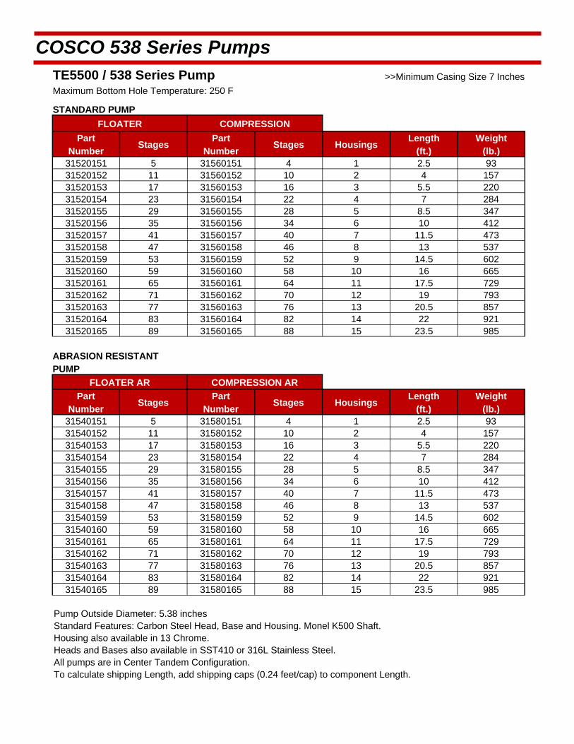
COSCO 538 Series Pumps
TE5500 / 538 Series Pump >>Minimum Casing Size 7 Inches
Maximum Bottom Hole Temperature: 250 F
STANDARD PUMP
FLOATER COMPRESSION
Part Number
Stages Part
Number Stages Housings
Length (ft.)
Weight (lb.)
31520151 5 31560151 4 1 2.5 93 31520152 11 31560152 10 2 4 157 31520153 17 31560153 16 3 5.5 220 31520154 23 31560154 22 4 7 284 31520155 29 31560155 28 5 8.5 347 31520156 35 31560156 34 6 10 412 31520157 41 31560157 40 7 11.5 473 31520158 47 31560158 46 8 13 537 31520159 53 31560159 52 9 14.5 602 31520160 59 31560160 58 10 16 665 31520161 65 31560161 64 11 17.5 729 31520162 71 31560162 70 12 19 793 31520163 77 31560163 76 13 20.5 857 31520164 83 31560164 82 14 22 921 31520165 89 31560165 88 15 23.5 985
ABRASION RESISTANT PUMP
FLOATER AR COMPRESSION AR
Part Number
Stages Part
Number Stages Housings
Length (ft.)
Weight (lb.)
31540151 5 31580151 4 1 2.5 93 31540152 11 31580152 10 2 4 157 31540153 17 31580153 16 3 5.5 220 31540154 23 31580154 22 4 7 284 31540155 29 31580155 28 5 8.5 347 31540156 35 31580156 34 6 10 412 31540157 41 31580157 40 7 11.5 473 31540158 47 31580158 46 8 13 537 31540159 53 31580159 52 9 14.5 602 31540160 59 31580160 58 10 16 665 31540161 65 31580161 64 11 17.5 729 31540162 71 31580162 70 12 19 793 31540163 77 31580163 76 13 20.5 857 31540164 83 31580164 82 14 22 921 31540165 89 31580165 88 15 23.5 985
Pump Outside Diameter: 5.38 inches Standard Features: Carbon Steel Head, Base and Housing. Monel K500 Shaft. Housing also available in 13 Chrome.
Heads and Bases also available in SST410 or 316L Stainless Steel.
All pumps are in Center Tandem Configuration. To calculate shipping Length, add shipping caps (0.24 feet/cap) to component Length.
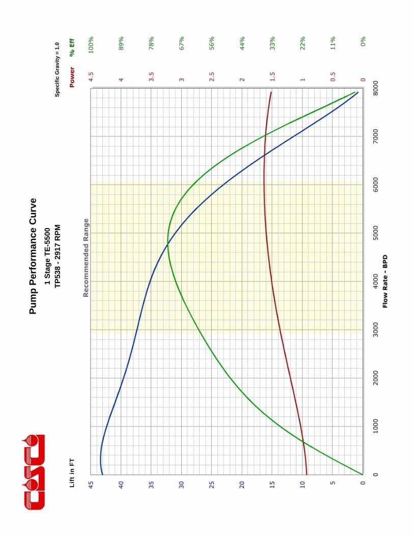
Pu
mp
Per
form
ance
Cu
rve
Sp
ecif
ic G
ravi
ty =
1.0
1 S
tag
e T
E-5
500
TP
538
- 29
17 R
PM
Lift
in F
T
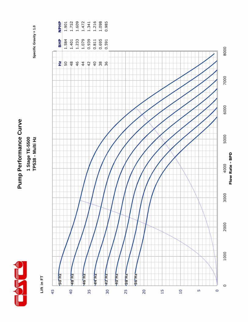
Pu
mp
Per
form
ance
Cu
rve
Sp
ecif
ic G
ravi
ty =
1.0
1 S
tag
e T
E-5
500
TP
538
- M
ult
i Hz
Lift
in F
T
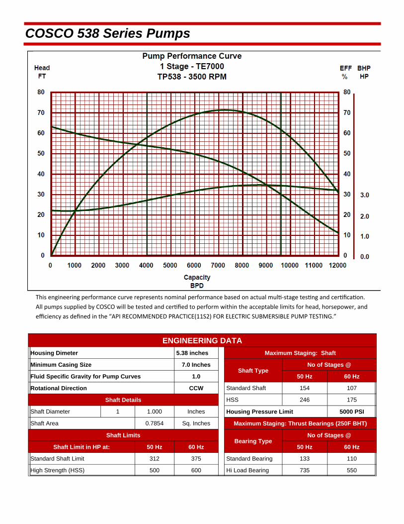
This engineering performance curve represents nominal performance based on actual mul ‐stage tes ng and cer fica on.
All pumps supplied by COSCO will be tested and cer fied to perform within the acceptable limits for head, horsepower, and
efficiency as defined in the “API RECOMMENDED PRACTICE(11S2) FOR ELECTRIC SUBMERSIBLE PUMP TESTING.”
COSCO 538 Series Pumps
ENGINEERING DATA
Housing Dimeter 5.38 inches Maximum Staging: Shaft
Minimum Casing Size 7.0 Inches Shaft Type
Fluid Specific Gravity for Pump Curves 1.0 50 Hz 60 Hz
Rotational Direction CCW Standard Shaft 154 107
Shaft Details HSS 246 175
Shaft Diameter 1 1.000 Inches Housing Pressure Limit 5000 PSI
Shaft Area 0.7854 Sq. Inches Maximum Staging: Thrust Bearings (250F BHT)
Shaft Limits Bearing Type
No of Stages @
Shaft Limit in HP at: 50 Hz 60 Hz 50 Hz 60 Hz
Standard Shaft Limit 312 375 Standard Bearing 133 110
High Strength (HSS) 500 600 Hi Load Bearing 735 550
No of Stages @
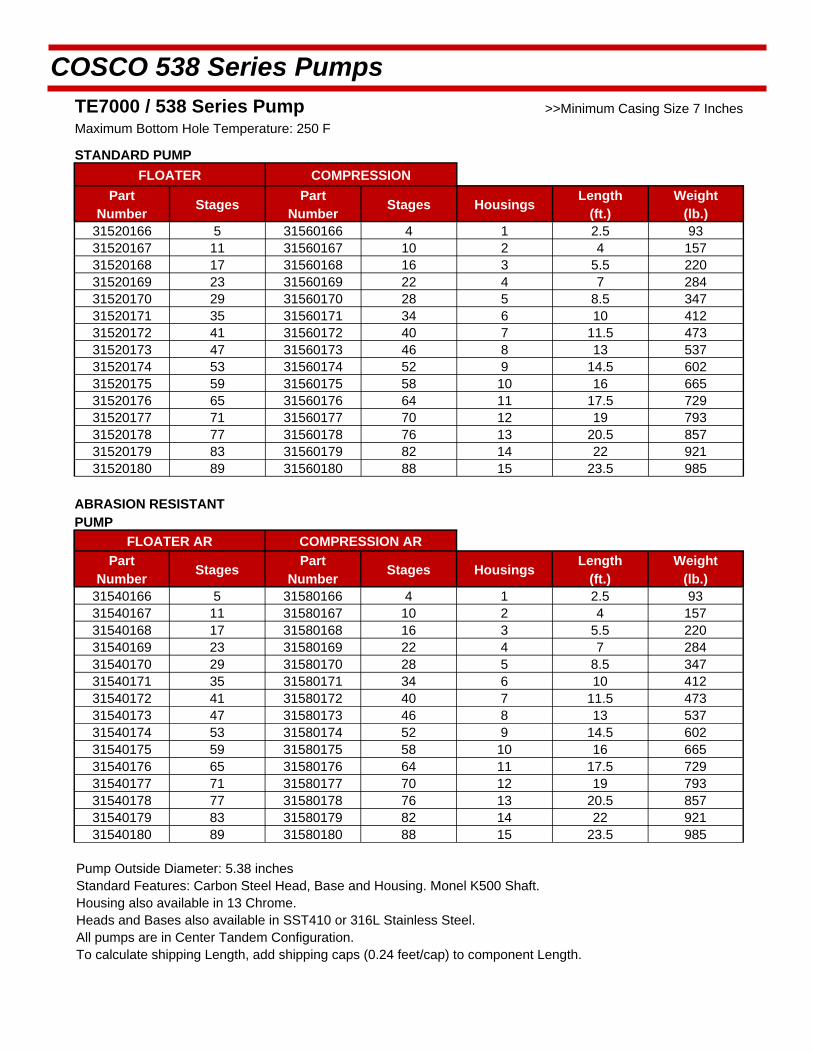
COSCO 538 Series Pumps
TE7000 / 538 Series Pump >>Minimum Casing Size 7 Inches
Maximum Bottom Hole Temperature: 250 F
STANDARD PUMP
FLOATER COMPRESSION
Part Number
Stages Part
Number Stages Housings
Length (ft.)
Weight (lb.)
31520166 5 31560166 4 1 2.5 93 31520167 11 31560167 10 2 4 157 31520168 17 31560168 16 3 5.5 220 31520169 23 31560169 22 4 7 284 31520170 29 31560170 28 5 8.5 347 31520171 35 31560171 34 6 10 412 31520172 41 31560172 40 7 11.5 473 31520173 47 31560173 46 8 13 537 31520174 53 31560174 52 9 14.5 602 31520175 59 31560175 58 10 16 665 31520176 65 31560176 64 11 17.5 729 31520177 71 31560177 70 12 19 793 31520178 77 31560178 76 13 20.5 857 31520179 83 31560179 82 14 22 921 31520180 89 31560180 88 15 23.5 985
ABRASION RESISTANT PUMP
FLOATER AR COMPRESSION AR
Part Number
Stages Part
Number Stages Housings
Length (ft.)
Weight (lb.)
31540166 5 31580166 4 1 2.5 93 31540167 11 31580167 10 2 4 157 31540168 17 31580168 16 3 5.5 220 31540169 23 31580169 22 4 7 284 31540170 29 31580170 28 5 8.5 347 31540171 35 31580171 34 6 10 412 31540172 41 31580172 40 7 11.5 473 31540173 47 31580173 46 8 13 537 31540174 53 31580174 52 9 14.5 602 31540175 59 31580175 58 10 16 665 31540176 65 31580176 64 11 17.5 729 31540177 71 31580177 70 12 19 793 31540178 77 31580178 76 13 20.5 857 31540179 83 31580179 82 14 22 921 31540180 89 31580180 88 15 23.5 985
Pump Outside Diameter: 5.38 inches Standard Features: Carbon Steel Head, Base and Housing. Monel K500 Shaft. Housing also available in 13 Chrome.
Heads and Bases also available in SST410 or 316L Stainless Steel.
All pumps are in Center Tandem Configuration. To calculate shipping Length, add shipping caps (0.24 feet/cap) to component Length.
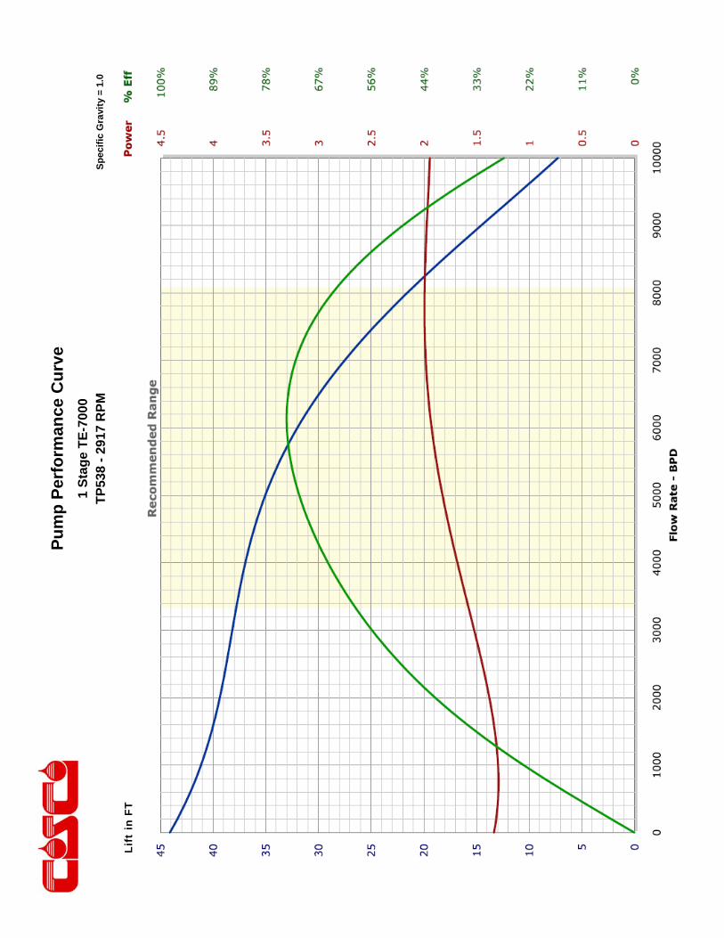
Pu
mp
Per
form
ance
Cu
rve
Sp
ecif
ic G
ravi
ty =
1.0
1 S
tag
e T
E-7
000
TP
538
- 29
17 R
PM
Lift
in F
T

Pu
mp
Per
form
ance
Cu
rve
Sp
ecif
ic G
ravi
ty =
1.0
1 S
tag
e T
E-7
000
TP
538
- M
ult
i Hz
Lift
in F
T

This engineering performance curve represents nominal performance based on actual mul ‐stage tes ng and cer fica on.
All pumps supplied by COSCO will be tested and cer fied to perform within the acceptable limits for head, horsepower, and
efficiency as defined in the “API RECOMMENDED PRACTICE(11S2) FOR ELECTRIC SUBMERSIBLE PUMP TESTING.”
COSCO 538 Series Pumps
ENGINEERING DATA
Housing Dimeter 5.38 inches Maximum Staging: Shaft
Minimum Casing Size 7.0 Inches Shaft Type
Fluid Specific Gravity for Pump Curves 1.0 50 Hz 60 Hz
Rotational Direction CCW Standard Shaft 159 111
Shaft Details HSS 257 179
Shaft Diameter 1 1.000 Inches Housing Pressure Limit 5000 PSI
Shaft Area 0.7854 Sq. Inches Maximum Staging: Thrust Bearings (250F BHT)
Shaft Limits Bearing Type
No of Stages @
Shaft Limit in HP at: 50 Hz 60 Hz 50 Hz 60 Hz
Standard Shaft Limit 312 375 Standard Bearing 136 114
High Strength (HSS) 500 600 Hi Load Bearing 752 570
No of Stages @

COSCO 538 Series Pumps
SN8500 / 538 Series Pump >>Minimum Casing Size 7 Inches
Maximum Bottom Hole Temperature: 250 F
STANDARD PUMP
FLOATER COMPRESSION
Part Number
Stages Part
Number Stages Housings
Length (ft.)
Weight (lb.)
31520181 5 31560181 4 1 2.5 93 31520182 10 31560182 9 2 4 157 31520183 15 31560183 14 3 5.5 220 31520184 21 31560184 20 4 7 284 31520185 26 31560185 25 5 8.5 347 31520186 31 31560186 30 6 10 412 31520187 37 31560187 36 7 11.5 473 31520188 42 31560188 41 8 13 537 31520189 47 31560189 46 9 14.5 602 31520190 53 31560190 52 10 16 665 31520191 58 31560191 57 11 17.5 729 31520192 63 31560192 62 12 19 793 31520193 68 31560193 67 13 20.5 857 31520194 74 31560194 73 14 22 921 31520195 79 31560195 78 15 23.5 985
ABRASION RESISTANT PUMP
FLOATER AR COMPRESSION AR
Part Number
Stages Part
Number Stages Housings
Length (ft.)
Weight (lb.)
31540181 5 31580181 4 1 2.5 93 31540182 10 31580182 9 2 4 157 31540183 15 31580183 14 3 5.5 220 31540184 21 31580184 20 4 7 284 31540185 26 31580185 25 5 8.5 347 31540186 31 31580186 30 6 10 412 31540187 37 31580187 36 7 11.5 473 31540188 42 31580188 41 8 13 537 31540189 47 31580189 46 9 14.5 602 31540190 53 31580190 52 10 16 665 31540191 58 31580191 57 11 17.5 729 31540192 63 31580192 62 12 19 793 31540193 68 31580193 67 13 20.5 857 31540194 74 31580194 73 14 22 921 31540195 79 31580195 78 15 23.5 985
Pump Outside Diameter: 5.38 inches Standard Features: Carbon Steel Head, Base and Housing. Monel K500 Shaft. Housing also available in 13 Chrome.
Heads and Bases also available in SST410 or 316L Stainless Steel.
All pumps are in Center Tandem Configuration. To calculate shipping Length, add shipping caps (0.24 feet/cap) to component Length.
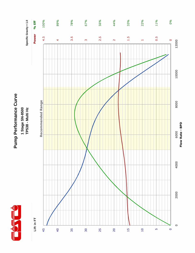
Pu
mp
Per
form
ance
Cu
rve
Sp
ecif
ic G
ravi
ty =
1.0
1 S
tag
e S
N-8
500
TP
538
- M
ult
i Hz
Lift
in F
T
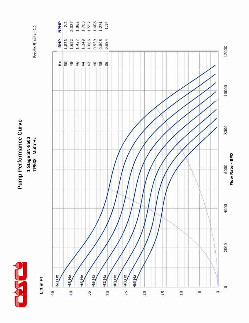
Pu
mp
Per
form
ance
Cu
rve
Sp
ecif
ic G
ravi
ty =
1.0
1 S
tag
e S
N-8
500
TP
538
- M
ult
i Hz
Lift
in F
T
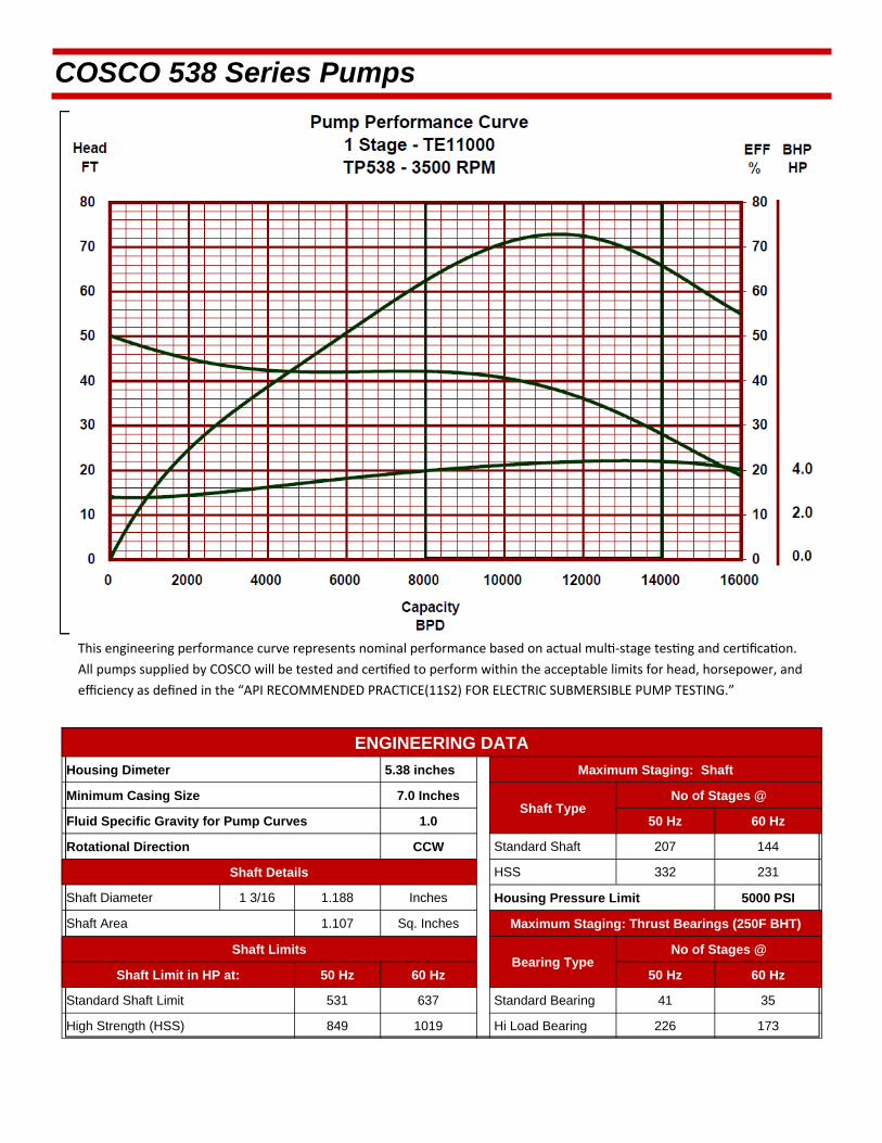
This engineering performance curve represents nominal performance based on actual mul ‐stage tes ng and cer fica on.
All pumps supplied by COSCO will be tested and cer fied to perform within the acceptable limits for head, horsepower, and
efficiency as defined in the “API RECOMMENDED PRACTICE(11S2) FOR ELECTRIC SUBMERSIBLE PUMP TESTING.”
COSCO 538 Series Pumps
ENGINEERING DATA
Housing Dimeter 5.38 inches Maximum Staging: Shaft
Minimum Casing Size 7.0 Inches Shaft Type
Fluid Specific Gravity for Pump Curves 1.0 50 Hz 60 Hz
Rotational Direction CCW Standard Shaft 207 144
Shaft Details HSS 332 231
Shaft Diameter 1 3/16 1.188 Inches Housing Pressure Limit 5000 PSI
Shaft Area 1.107 Sq. Inches Maximum Staging: Thrust Bearings (250F BHT)
Shaft Limits Bearing Type
No of Stages @
Shaft Limit in HP at: 50 Hz 60 Hz 50 Hz 60 Hz
Standard Shaft Limit 531 637 Standard Bearing 41 35
High Strength (HSS) 849 1019 Hi Load Bearing 226 173
No of Stages @
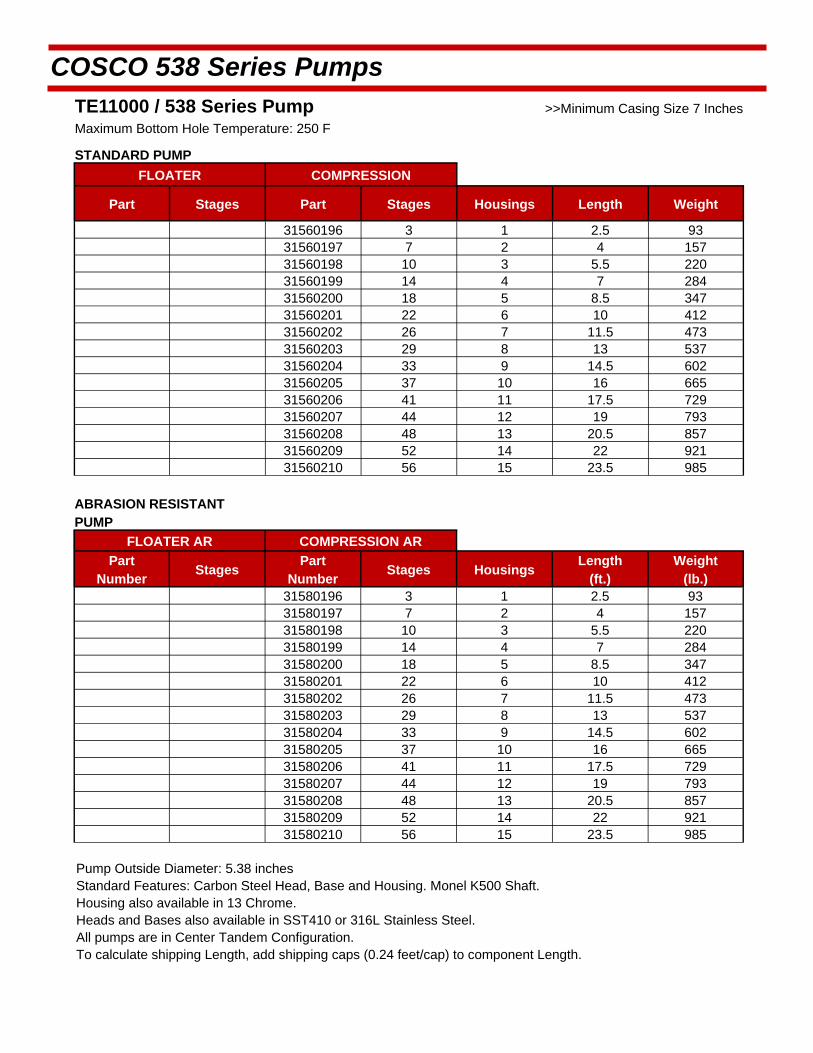
COSCO 538 Series Pumps
TE11000 / 538 Series Pump >>Minimum Casing Size 7 Inches
Maximum Bottom Hole Temperature: 250 F
STANDARD PUMP
FLOATER COMPRESSION
Part Stages Part Stages Housings Length Weight
31560196 3 1 2.5 93 31560197 7 2 4 157 31560198 10 3 5.5 220 31560199 14 4 7 284 31560200 18 5 8.5 347 31560201 22 6 10 412 31560202 26 7 11.5 473 31560203 29 8 13 537 31560204 33 9 14.5 602 31560205 37 10 16 665 31560206 41 11 17.5 729 31560207 44 12 19 793 31560208 48 13 20.5 857 31560209 52 14 22 921 31560210 56 15 23.5 985
ABRASION RESISTANT PUMP
FLOATER AR COMPRESSION AR
Part Number
Stages Part
Number Stages Housings
Length (ft.)
Weight (lb.)
31580196 3 1 2.5 93 31580197 7 2 4 157 31580198 10 3 5.5 220 31580199 14 4 7 284 31580200 18 5 8.5 347 31580201 22 6 10 412 31580202 26 7 11.5 473 31580203 29 8 13 537 31580204 33 9 14.5 602 31580205 37 10 16 665 31580206 41 11 17.5 729 31580207 44 12 19 793 31580208 48 13 20.5 857 31580209 52 14 22 921 31580210 56 15 23.5 985
Pump Outside Diameter: 5.38 inches Standard Features: Carbon Steel Head, Base and Housing. Monel K500 Shaft. Housing also available in 13 Chrome.
Heads and Bases also available in SST410 or 316L Stainless Steel.
All pumps are in Center Tandem Configuration. To calculate shipping Length, add shipping caps (0.24 feet/cap) to component Length.
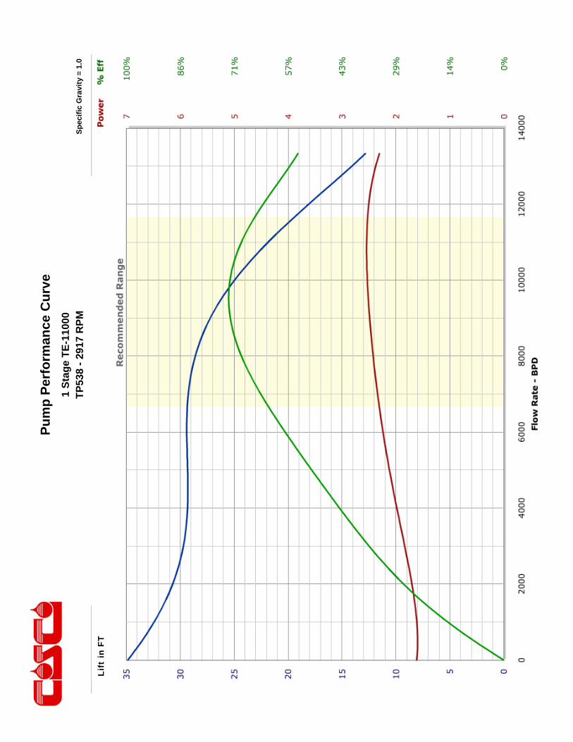
Pu
mp
Per
form
ance
Cu
rve
Sp
ecif
ic G
ravi
ty =
1.0
1 S
tag
e T
E-1
1000
T
P53
8 -
2917
RP
M
Lift
in F
T
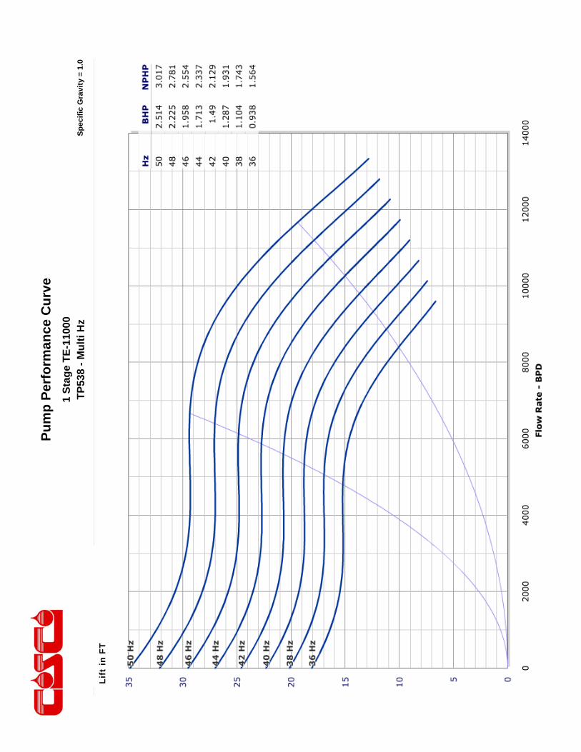
Pu
mp
Per
form
ance
Cu
rve
Sp
ecif
ic G
ravi
ty =
1.0
1 S
tag
e T
E-1
1000
T
P53
8 -
Mu
lti H
z
Lift
in F
T
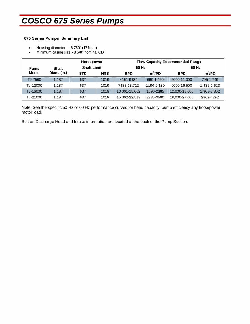
COSCO 675 Series Pumps 675 Series Pumps Summary List
Housing diameter - 6.750” (171mm) Minimum casing size - 8 5/8" nominal OD
Horsepower Flow Capacity Recommended Range
Pump Model
Shaft Diam. (in.)
Shaft Limit 50 Hz 60 Hz
STD HSS BPD m3/PD BPD m3/PD
TJ-7500 1.187 637 1019 4151-9184 660-1,460 5000-11,000 795-1,749
TJ-12000 1.187 637 1019 7485-13,712 1190-2,180 9000-16,500 1,431-2,623
TJ-16000 1.187 637 1019 10,001-15,002 1590-2385 12,000-18,000 1,908-2,862
TJ-21000 1.187 637 1019 15,002-22,519 2385-3580 18,000-27,000 2862-4292
Note: See the specific 50 Hz or 60 Hz performance curves for head capacity, pump efficiency any horsepower motor load. Bolt on Discharge Head and Intake information are located at the back of the Pump Section.

This engineering performance curve represents nominal performance based on actual mul ‐stage tes ng and cer fica on. All pumps supplied by COSCO will be tested and cer fied to perform within the acceptable limits for head, horsepower, and efficiency as defined in the “API RECOMMENDED PRACTICE(11S2) FOR ELECTRIC SUBMERSIBLE PUMP TESTING”.
COSCO 675 Series Pumps
ENGINEERING DATA
Housing Diameter 6.75 inches Maximum Staging: Shaft
Minimum Casing Size 8 5/8 Inch Shaft Type
Fluid Specific Gravity for Pump Curves 1.0 50 Hz 60 Hz
Rotational Direction CCW Standard Shaft 142 99
Shaft Details HSS 228 159
Shaft Diameter 1 3/16 1.1875 Inches Housing Pressure Limit 3000 PSI
Shaft Area 1.107 Sq. Inches Maximum Staging: Thrust Bearings (250F BHT)
Shaft Limits Bearing Type
No of Stages @
Shaft Limit in HP at: 50 Hz 60 Hz 50 Hz 60 Hz
Standard Shaft Limit 531 637 Standard Bearing
High Strength (HSS) 849 1019 Hi Load Bearing
No of Stages @

COSCO 675 Series Pumps
TJ7500 / 675 Series Pump >>Minimum Casing Size 8 5/8 Inches Maximum Bottom Hole Temperature: 250 F
STANDARD PUMP
COMPRESSION COMPRESSION AR
Part Number Stages
Part Number Stages Housings
Length (ft.)
Weight (lb.)
31660001 2 31680001 2 1 2.7 210
31660002 6 31680002 6 2 4 327
31660003 9 31680003 9 3 5.4 419
31660004 12 31680004 12 4 6.8 511
31660005 15 31680005 15 5 8.2 603
31660006 19 31680006 19 6 9.5 714
31660007 22 31680007 22 7 10.9 806
31660008 25 31680008 25 8 12.3 898
31660009 29 31680009 29 9 13.7 1009
31660010 32 31680010 32 10 15 1104
31660011 35 31680011 35 11 16.4 1193
31660012 39 31680012 39 12 17.8 1304
31660013 42 31680013 42 13 19.2 1396
31660014 45 31680014 45 14 20.5 1488
31660015 48 31680015 48 15 21.9 1580
Pump Outside Diameter: 6.75 inches Standard Features: Carbon Steel Head, Base and Housing. Monel K500 Shaft. Housing also available in 13 Chrome.
Heads and Bases also available in SST410 or 316L Stainless Steel.
All pumps are in Center Tandem Configuration. To calculate shipping length, add shipping caps (0.06 feet upper / 0.24 feet/cap) to component length.
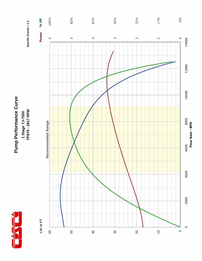
Pu
mp
Per
form
ance
Cu
rve
Sp
ecif
ic G
ravi
ty =
1.0
1 S
tag
e T
J-75
00
TP
675
- 29
17 R
PM
Li
ft in
FT

Pu
mp
Per
form
ance
Cu
rve
Sp
ecif
ic G
ravi
ty =
1.0
1 S
tag
e T
J-75
00
TP
675
- M
ult
i Hz
Lift
in F
T

This engineering performance curve represents nominal performance based on actual mul ‐stage tes ng and cer fica on. All pumps supplied by COSCO will be tested and cer fied to perform within the acceptable limits for head, horsepower, and efficiency as defined in the “API RECOMMENDED PRACTICE(11S2) FOR ELECTRIC SUBMERSIBLE PUMP TESTING”.
COSCO 675 Series Pumps
ENGINEERING DATA
Housing Diameter 6.75 inches Maximum Staging: Shaft
Minimum Casing Size 8 5/8 Inch Shaft Type
Fluid Specific Gravity for Pump Curves 1.0 50 Hz 60 Hz
Rotational Direction CCW Standard Shaft 70 49
Shaft Details HSS 112 78
Shaft Diameter 1 3/16 1.1875 Inches Housing Pressure Limit 3000 PSI
Shaft Area 1.107 Sq. Inches Maximum Staging: Thrust Bearings (250F BHT)
Shaft Limits Bearing Type
No of Stages @
Shaft Limit in HP at: 50 Hz 60 Hz 50 Hz 60 Hz
Standard Shaft Limit 531 637 Standard Bearing
High Strength (HSS) 849 1019 Hi Load Bearing
No of Stages @
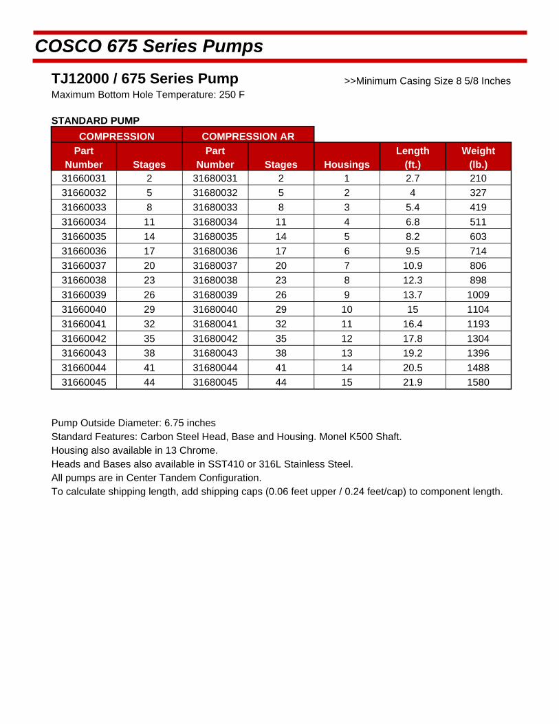
COSCO 675 Series Pumps
TJ12000 / 675 Series Pump >>Minimum Casing Size 8 5/8 Inches Maximum Bottom Hole Temperature: 250 F
STANDARD PUMP
COMPRESSION COMPRESSION AR
Part Number Stages
Part Number Stages Housings
Length (ft.)
Weight (lb.)
31660031 2 31680031 2 1 2.7 210
31660032 5 31680032 5 2 4 327
31660033 8 31680033 8 3 5.4 419
31660034 11 31680034 11 4 6.8 511
31660035 14 31680035 14 5 8.2 603
31660036 17 31680036 17 6 9.5 714
31660037 20 31680037 20 7 10.9 806
31660038 23 31680038 23 8 12.3 898
31660039 26 31680039 26 9 13.7 1009
31660040 29 31680040 29 10 15 1104
31660041 32 31680041 32 11 16.4 1193
31660042 35 31680042 35 12 17.8 1304
31660043 38 31680043 38 13 19.2 1396
31660044 41 31680044 41 14 20.5 1488
31660045 44 31680045 44 15 21.9 1580
Pump Outside Diameter: 6.75 inches Standard Features: Carbon Steel Head, Base and Housing. Monel K500 Shaft. Housing also available in 13 Chrome.
Heads and Bases also available in SST410 or 316L Stainless Steel.
All pumps are in Center Tandem Configuration. To calculate shipping length, add shipping caps (0.06 feet upper / 0.24 feet/cap) to component length.

Pu
mp
Per
form
ance
Cu
rve
Sp
ecif
ic G
ravi
ty =
1.0
1 S
tag
e T
J-12
000
TP
675
- 29
17 R
PM
Li
ft in
FT
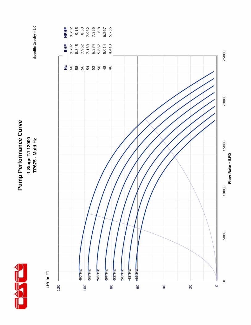
Pu
mp
Per
form
ance
Cu
rve
Sp
ecif
ic G
ravi
ty =
1.0
1 S
tag
e T
J-12
000
TP
675
- M
ult
i Hz
Lift
in F
T

This engineering performance curve represents nominal performance based on actual mul ‐stage tes ng and cer fica on. All pumps supplied by COSCO will be tested and cer fied to perform within the acceptable limits for head, horsepower, and efficiency as defined in the “API RECOMMENDED PRACTICE(11S2) FOR ELECTRIC SUBMERSIBLE PUMP TESTING”.
COSCO 675 Series Pumps
ENGINEERING DATA
Housing Diameter 6.75 inches Maximum Staging: Shaft
Minimum Casing Size 8 5/8 Inch Shaft Type
Fluid Specific Gravity for Pump Curves 1.0 50 Hz 60 Hz
Rotational Direction CCW Standard Shaft 82 57
Shaft Details HSS 132 92
Shaft Diameter 1 3/16 1.1875 Inches Housing Pressure Limit 3000 PSI
Shaft Area 1.107 Sq. Inches Maximum Staging: Thrust Bearings (250F BHT)
Shaft Limits Bearing Type
No of Stages @
Shaft Limit in HP at: 50 Hz 60 Hz 50 Hz 60 Hz
Standard Shaft Limit 531 637 Standard Bearing
High Strength (HSS) 849 1019 Hi Load Bearing
No of Stages @

COSCO 675 Series Pumps
TJ16000 / 675 Series Pump >>Minimum Casing Size 8 5/8 Inches Maximum Bottom Hole Temperature: 250 F
STANDARD PUMP
COMPRESSION COMPRESSION AR
Part Number Stages
Part Number Stages Housings
Length (ft.)
Weight (lb.)
31660046 2 31680046 2 1 2.7 210
31660047 6 31680047 6 2 4 327
31660048 9 31680048 9 3 5.4 419
31660049 12 31680049 12 4 6.8 511
31660050 15 31680050 15 5 8.2 603
31660051 19 31680051 19 6 9.5 714
31660052 22 31680052 22 7 10.9 806
31660053 25 31680053 25 8 12.3 898
31660054 29 31680054 29 9 13.7 1009
31660055 32 31680055 32 10 15 1104
31660056 35 31680056 35 11 16.4 1193
31660057 39 31680057 39 12 17.8 1304
31660058 42 31680058 42 13 19.2 1396
31660059 45 31680059 45 14 20.5 1488
31660060 48 31680060 48 15 21.9 1580
Pump Outside Diameter: 6.75 inches Standard Features: Carbon Steel Head, Base and Housing. Monel K500 Shaft. Housing also available in 13 Chrome.
Heads and Bases also available in SST410 or 316L Stainless Steel.
All pumps are in Center Tandem Configuration. To calculate shipping length, add shipping caps (0.06 feet upper / 0.24 feet/cap) to component length.

Pu
mp
Per
form
ance
Cu
rve
Sp
ecif
ic G
ravi
ty =
1.0
1 S
tag
e T
J-16
000
TP
675
- 29
17 R
PM
Li
ft in
FT
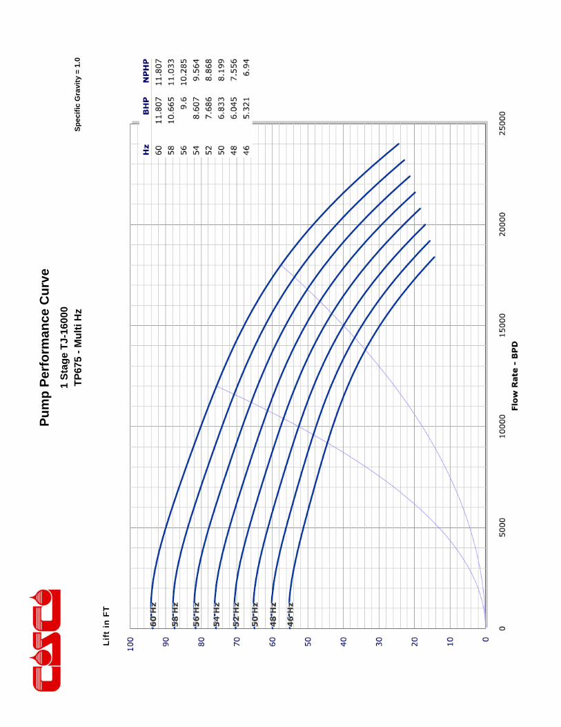
Pu
mp
Per
form
ance
Cu
rve
Sp
ecif
ic G
ravi
ty =
1.0
1 S
tag
e T
J-16
000
TP
675
- M
ult
i Hz
Li
ft in
FT

This engineering performance curve represents nominal performance based on actual mul ‐stage tes ng and cer fica on. All pumps supplied by COSCO will be tested and cer fied to perform within the acceptable limits for head, horsepower, and efficiency as defined in the “API RECOMMENDED PRACTICE(11S2) FOR ELECTRIC SUBMERSIBLE PUMP TESTING”.
COSCO 675 Series Pumps
ENGINEERING DATA
Housing Diameter 6.75 inches Maximum Staging: Shaft
Minimum Casing Size 8 5/8 Inch Shaft Type
Fluid Specific Gravity for Pump Curves 1.0 50 Hz 60 Hz
Rotational Direction CCW Standard Shaft 76 53
Shaft Details HSS 120 84
Shaft Diameter 1 3/16 1.1875 Inches Housing Pressure Limit 3000 PSI
Shaft Area 1.107 Sq. Inches Maximum Staging: Thrust Bearings (250F BHT)
Shaft Limits Bearing Type
No of Stages @
Shaft Limit in HP at: 50 Hz 60 Hz 50 Hz 60 Hz
Standard Shaft Limit 531 637 Standard Bearing
High Strength (HSS) 849 1019 Hi Load Bearing
No of Stages @

COSCO 675 Series Pumps
TJ21000 / 675 Series Pump >>Minimum Casing Size 8 5/8 Inches Maximum Bottom Hole Temperature: 250 F
STANDARD PUMP
COMPRESSION COMPRESSION AR
Part Number Stages
Part Number Stages Housings
Length (ft.)
Weight (lb.)
31660061 2 31680061 2 1 2.7 210
31660062 5 31680062 5 2 4 327
31660063 8 31680063 8 3 5.4 419
31660064 11 31680064 11 4 6.8 511
31660065 14 31680065 14 5 8.2 603
31660066 17 31680066 17 6 9.5 714
31660067 20 31680067 20 7 10.9 806
31660068 23 31680068 23 8 12.3 898
31660069 26 31680069 26 9 13.7 1009
31660070 29 31680070 29 10 15 1104
31660071 32 31680071 32 11 16.4 1193
31660072 35 31680072 35 12 17.8 1304
31660073 38 31680073 38 13 19.2 1396
31660074 41 31680074 41 14 20.5 1488
31660075 44 31680075 44 15 21.9 1580
Pump Outside Diameter: 6.75 inches Standard Features: Carbon Steel Head, Base and Housing. Monel K500 Shaft. Housing also available in 13 Chrome.
Heads and Bases also available in SST410 or 316L Stainless Steel.
All pumps are in Center Tandem Configuration. To calculate shipping length, add shipping caps (0.06 feet upper / 0.24 feet/cap) to component length.

Pu
mp
Per
form
ance
Cu
rve
Sp
ecif
ic G
ravi
ty =
1.0
1 S
tag
e T
J-21
000

Pu
mp
Per
form
ance
Cu
rve
Sp
ecif
ic G
ravi
ty =
1.0
1 S
tag
e T
J-21
000
TP
675
- M
ult
i Hz
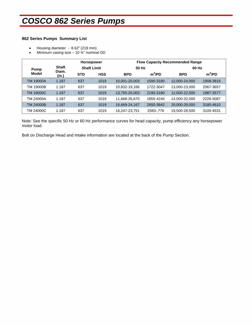
COSCO 862 Series Pumps 862 Series Pumps Summary List
Housing diameter - 8.62” (219 mm) Minimum casing size – 10 ¾” nominal OD
Horsepower Flow Capacity Recommended Range
Pump Model
Shaft Diam. (in.)
Shaft Limit 50 Hz 60 Hz
STD HSS BPD m3/PD BPD m3/PD
TM 19000A 1.187 637 1019 10,001-20,003 1590-3180 12,000-24,000 1908-3816
TM 19000B 1.187 637 1019 10,832-19,166 1722-3047 13,000-23,000 2067-3657
TM 19000C 1.187 637 1019 13,755-20,003 2190-3180 12,500-22,500 1987-3577
TM 24000A 1.187 637 1019 11,668-26,670 1855-4240 14,000-32,000 2226-5087
TM 24000B 1.187 637 1019 16,669-24,167 2650-3842 20,000-29,000 3180-4610
TM 24000C 1.187 637 1019 16,247-23,751 2583-,776 19,500-28,500 3100-4531
Note: See the specific 50 Hz or 60 Hz performance curves for head capacity, pump efficiency any horsepower motor load. Bolt on Discharge Head and Intake information are located at the back of the Pump Section.

This engineering performance curve represents nominal performance based on actual mul ‐stage tes ng and cer fica on. All pumps supplied by COSCO will be tested and cer fied to perform within the acceptable limits for head, horsepower, and efficiency as defined in the “API RECOMMENDED PRACTICE(11S2) FOR ELECTRIC SUBMERSIBLE PUMP TESTING”.
COSCO 862 Series Pumps
ENGINEERING DATA
Housing Diameter 8.62 inches Maximum Staging: Shaft
Minimum Casing Size 10 3/4 Inches Shaft Type
Fluid Specific Gravity for Pump Curves 1.0 50 Hz 60 Hz
Rotational Direction CCW Standard Shaft 44 31
Shaft Details HSS 72 50
Shaft Diameter 1 3/16 1.1875 Inches Housing Pressure Limit 2000 PSI
Shaft Area 1.107 Sq. Inches Maximum Staging: Thrust Bearings (250F BHT)
Shaft Limits Bearing Type
No of Stages @
Shaft Limit in HP at: 50 Hz 60 Hz 50 Hz 60 Hz
Standard Shaft Limit 531 637 Standard Bearing
High Strength (HSS) 849 1019 Hi Load Bearing
No of Stages @

COSCO 862 Series Pumps
TM19000A / 862 Series Pump >>Minimum Casing Size 10 3/4 Inches Maximum Bottom Hole Temperature: 250 F
STANDARD PUMP
COMPRESSION COMPRESSION AR
Part Number Stages
Part Number Stages Housings
Length (ft.)
Weight (lb.)
31860001 3 31880001 3 3 3.3 528
31860002 4 31880002 4 4 3.9 587
31860003 5 31880003 5 5 4.5 662
31860004 6 31880004 6 6 5.1 729
31860005 7 31880005 7 7 5.7 789
31860006 8 31880006 8 8 6.3 863
31860007 9 31880007 9 9 6.9 931
31860008 10 31880008 10 10 7.5 991
31860009 11 31880009 11 11 8.1 1058
31860010 12 31880010 12 12 8.7 1126
31860011 13 31880011 13 13 9.3 1193
31860012 14 31880012 14 14 9.9 1260
31860013 15 31880013 15 15 10.6 1327
31860014 16 31880014 16 16 11.2 1395
31860015 17 31880015 17 17 11.8 1466
31860016 18 31880016 18 18 12.4 1533
31860017 19 31880017 19 19 13 1596
31860018 20 31880018 20 20 13.6 1664
31860019 21 31880019 21 21 14.2 1734
31860020 22 31880020 22 22 14.8 1801
31860021 23 31880021 23 23 15.4 1866
31860022 24 31880022 24 24 16 1933
31860023 25 31880023 25 25 16.6 2003
31860024 26 31880024 26 26 17.2 2071
31860025 27 31880025 27 27 17.8 2138
31860026 28 31880026 28 28 18.4 2202
31860027 29 31880027 29 29 19 2272
31860028 30 31880028 30 30 19.6 2339
31860029 31 31880029 31 31 20.2 2407
31860030 32 31880030 32 32 20.8 2474
Pump Outside Diameter: 8.62 inches Standard Features: Carbon Steel Head, Base and Housing. Monel K500 Shaft. Housing also available in 13 Chrome.
Heads and Bases also available in SST410 or 316L Stainless Steel.
All pumps are in Center Tandem Configuration. To calculate shipping length, add shipping caps (0.06 feet upper / 0.30 feet lower) to component length.
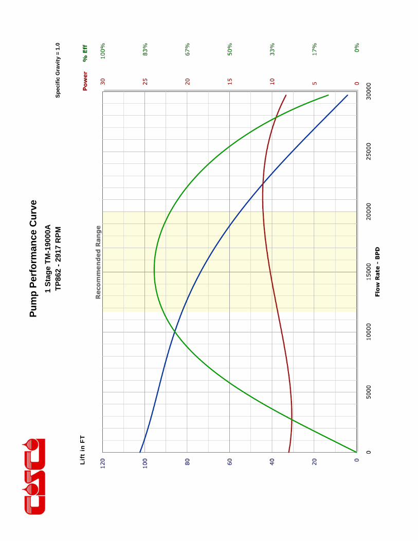
Pu
mp
Per
form
ance
Cu
rve
Sp
ecif
ic G
ravi
ty =
1.0
1 S
tag
e T
M-1
9000
A
TP
862
- 29
17 R
PM
Li
ft in
FT
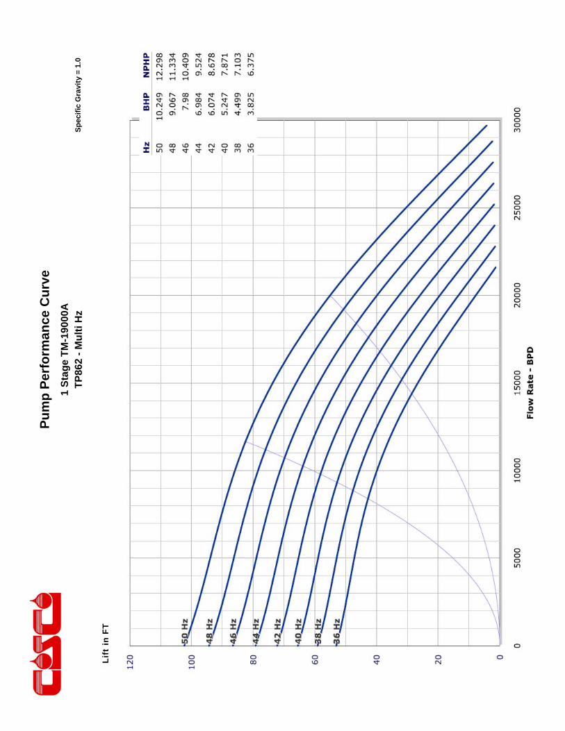
Pu
mp
Per
form
ance
Cu
rve
Sp
ecif
ic G
ravi
ty =
1.0
1 S
tag
e T
M-1
9000
A
TP
862
- M
ult
i Hz
Li
ft in
FT

This engineering performance curve represents nominal performance based on actual mul ‐stage tes ng and cer fica on. All pumps supplied by COSCO will be tested and cer fied to perform within the acceptable limits for head, horsepower, and efficiency as defined in the “API RECOMMENDED PRACTICE(11S2) FOR ELECTRIC SUBMERSIBLE PUMP TESTING”.
COSCO 862 Series Pumps
ENGINEERING DATA
Housing Diameter 8.62 inches Maximum Staging: Shaft
Minimum Casing Size 10 3/4 Inches Shaft Type
Fluid Specific Gravity for Pump Curves 1.0 50 Hz 60 Hz
Rotational Direction CCW Standard Shaft 64 44
Shaft Details HSS 102 71
Shaft Diameter 1 3/16 1.1875 Inches Housing Pressure Limit 2000 PSI
Shaft Area 1.107 Sq. Inches Maximum Staging: Thrust Bearings (250F BHT)
Shaft Limits Bearing Type
No of Stages @
Shaft Limit in HP at: 50 Hz 60 Hz 50 Hz 60 Hz
Standard Shaft Limit 531 637 Standard Bearing
High Strength (HSS) 849 1019 Hi Load Bearing
No of Stages @

COSCO 862 Series Pumps
TM19000B / 862 Series Pump >>Minimum Casing Size 10 3/4 Inches Maximum Bottom Hole Temperature: 250 F
STANDARD PUMP
COMPRESSION COMPRESSION AR
Part Number Stages
Part Number Stages Housings
Length (ft.)
Weight (lb.)
31860031 3 31880031 3 3 3.3 528
31860032 4 31880032 4 4 3.9 587
31860033 5 31880033 5 5 4.5 662
31860034 6 31880034 6 6 5.1 729
31860035 7 31880035 7 7 5.7 789
31860036 8 31880036 8 8 6.3 863
31860037 9 31880037 9 9 6.9 931
31860038 10 31880038 10 10 7.5 991
31860039 11 31880039 11 11 8.1 1058
31860040 12 31880040 12 12 8.7 1126
31860041 13 31880041 13 13 9.3 1193
31860042 14 31880042 14 14 9.9 1260
31860043 15 31880043 15 15 10.6 1327
31860044 16 31880044 16 16 11.2 1395
31860045 17 31880045 17 17 11.8 1466
31860046 18 31880046 18 18 12.4 1533
31860047 19 31880047 19 19 13 1596
31860048 20 31880048 20 20 13.6 1664
31860049 21 31880049 21 21 14.2 1734
31860050 22 31880050 22 22 14.8 1801
31860051 23 31880051 23 23 15.4 1866
31860052 24 31880052 24 24 16 1933
31860053 25 31880053 25 25 16.6 2003
31860054 26 31880054 26 26 17.2 2071
31860055 27 31880055 27 27 17.8 2138
31860056 28 31880056 28 28 18.4 2202
31860057 29 31880057 29 29 19 2272
31860058 30 31880058 30 30 19.6 2339
31860059 31 31880059 31 31 20.2 2407
31860060 32 31880060 32 32 20.8 2474
Pump Outside Diameter: 8.62 inches Standard Features: Carbon Steel Head, Base and Housing. Monel K500 Shaft. Housing also available in 13 Chrome.
Heads and Bases also available in SST410 or 316L Stainless Steel.
All pumps are in Center Tandem Configuration. To calculate shipping length, add shipping caps (0.06 feet upper / 0.30 feet lower) to component length.
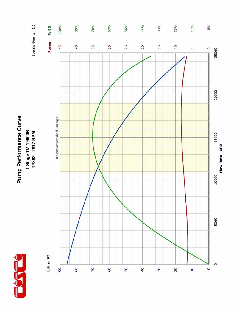
Pu
mp
Per
form
ance
Cu
rve
Sp
ecif
ic G
ravi
ty =
1.0
1 S
tag
e T
M-1
9000
B
TP
862
- 29
17 R
PM
Li
ft in
FT
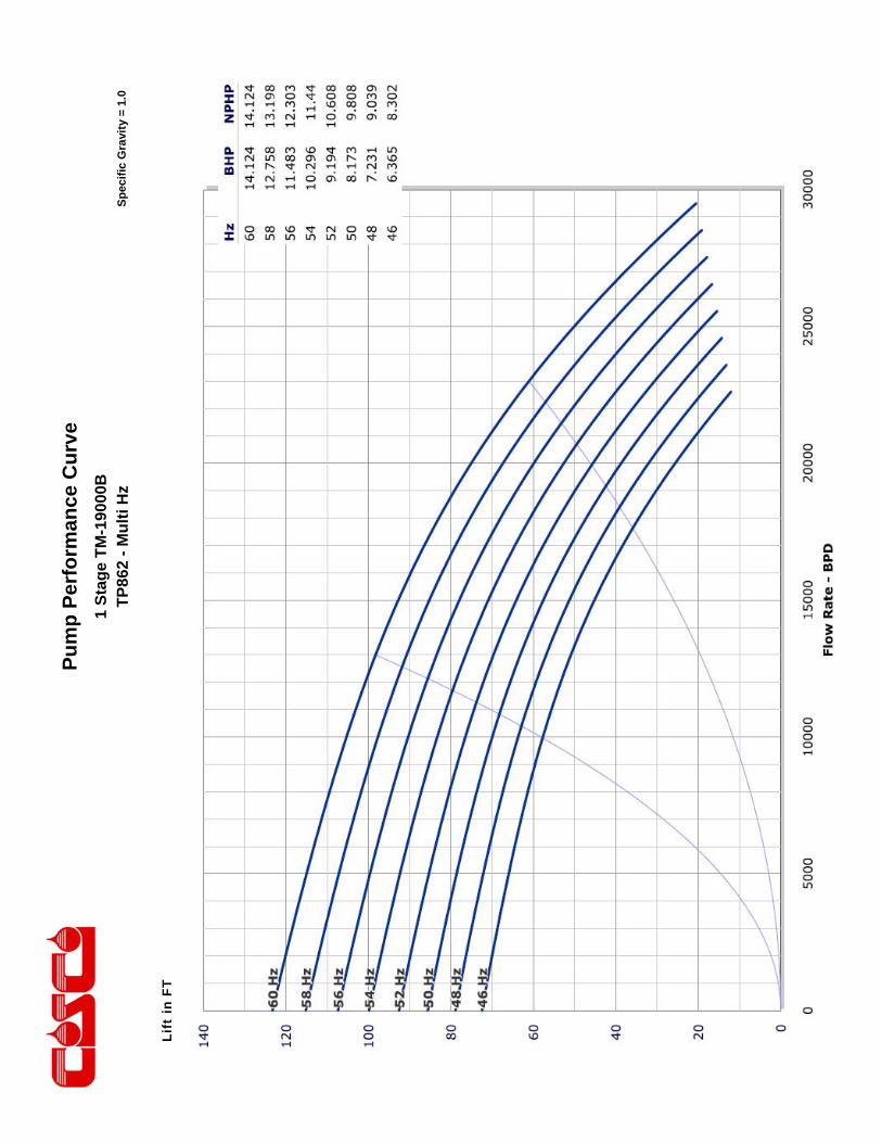
Pu
mp
Per
form
ance
Cu
rve
Sp
ecif
ic G
ravi
ty =
1.0
1 S
tag
e T
M-1
9000
B
TP
862
- M
ult
i Hz
Li
ft in
FT

This engineering performance curve represents nominal performance based on actual mul ‐stage tes ng and cer fica on. All pumps supplied by COSCO will be tested and cer fied to perform within the acceptable limits for head, horsepower, and efficiency as defined in the “API RECOMMENDED PRACTICE(11S2) FOR ELECTRIC SUBMERSIBLE PUMP TESTING”.
COSCO 862 Series Pumps
ENGINEERING DATA
Housing Diameter 8.62 inches Maximum Staging: Shaft
Minimum Casing Size 10 3/4 Inches Shaft Type
Fluid Specific Gravity for Pump Curves 1.0 50 Hz 60 Hz
Rotational Direction CCW Standard Shaft 73 51
Shaft Details HSS 117 81
Shaft Diameter 1 3/16 1.1875 Inches Housing Pressure Limit 2000 PSI
Shaft Area 1.107 Sq. Inches Maximum Staging: Thrust Bearings (250F BHT)
Shaft Limits Bearing Type
No of Stages @
Shaft Limit in HP at: 50 Hz 60 Hz 50 Hz 60 Hz
Standard Shaft Limit 531 637 Standard Bearing
High Strength (HSS) 849 1019 Hi Load Bearing
No of Stages @
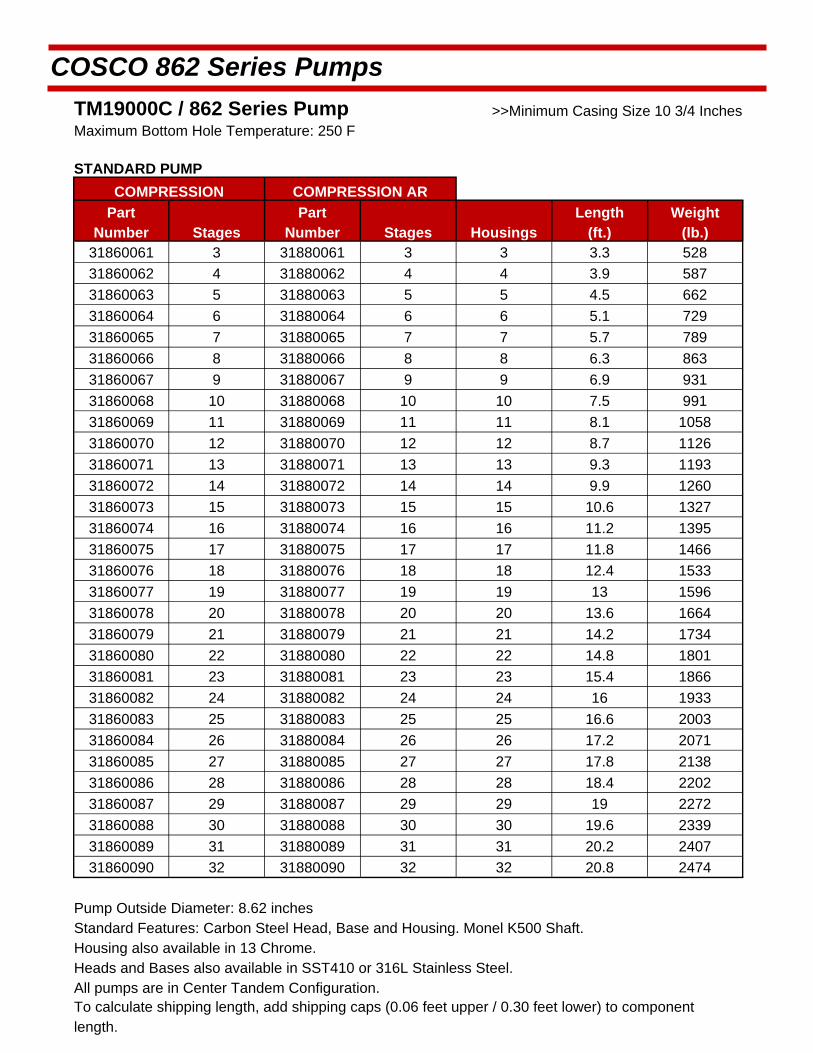
COSCO 862 Series Pumps
TM19000C / 862 Series Pump >>Minimum Casing Size 10 3/4 Inches Maximum Bottom Hole Temperature: 250 F
STANDARD PUMP
COMPRESSION COMPRESSION AR
Part Number Stages
Part Number Stages Housings
Length (ft.)
Weight (lb.)
31860061 3 31880061 3 3 3.3 528
31860062 4 31880062 4 4 3.9 587
31860063 5 31880063 5 5 4.5 662
31860064 6 31880064 6 6 5.1 729
31860065 7 31880065 7 7 5.7 789
31860066 8 31880066 8 8 6.3 863
31860067 9 31880067 9 9 6.9 931
31860068 10 31880068 10 10 7.5 991
31860069 11 31880069 11 11 8.1 1058
31860070 12 31880070 12 12 8.7 1126
31860071 13 31880071 13 13 9.3 1193
31860072 14 31880072 14 14 9.9 1260
31860073 15 31880073 15 15 10.6 1327
31860074 16 31880074 16 16 11.2 1395
31860075 17 31880075 17 17 11.8 1466
31860076 18 31880076 18 18 12.4 1533
31860077 19 31880077 19 19 13 1596
31860078 20 31880078 20 20 13.6 1664
31860079 21 31880079 21 21 14.2 1734
31860080 22 31880080 22 22 14.8 1801
31860081 23 31880081 23 23 15.4 1866
31860082 24 31880082 24 24 16 1933
31860083 25 31880083 25 25 16.6 2003
31860084 26 31880084 26 26 17.2 2071
31860085 27 31880085 27 27 17.8 2138
31860086 28 31880086 28 28 18.4 2202
31860087 29 31880087 29 29 19 2272
31860088 30 31880088 30 30 19.6 2339
31860089 31 31880089 31 31 20.2 2407
31860090 32 31880090 32 32 20.8 2474
Pump Outside Diameter: 8.62 inches Standard Features: Carbon Steel Head, Base and Housing. Monel K500 Shaft. Housing also available in 13 Chrome.
Heads and Bases also available in SST410 or 316L Stainless Steel.
All pumps are in Center Tandem Configuration. To calculate shipping length, add shipping caps (0.06 feet upper / 0.30 feet lower) to component length.
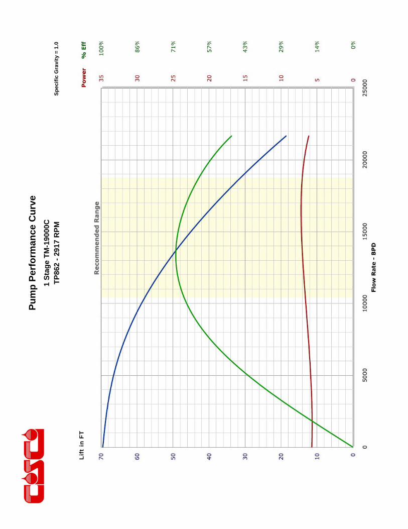
Pu
mp
Per
form
ance
Cu
rve
Sp
ecif
ic G
ravi
ty =
1.0
1 S
tag
e T
M-1
9000
C
TP
862
- 29
17 R
PM
Li
ft in
FT

Pu
mp
Per
form
ance
Cu
rve
Sp
ecif
ic G
ravi
ty =
1.0
1 S
tag
e T
M-1
9000
C
TP
862
- M
ult
i Hz
Li
ft in
FT

This engineering performance curve represents nominal performance based on actual mul ‐stage tes ng and cer fica on. All pumps supplied by COSCO will be tested and cer fied to perform within the acceptable limits for head, horsepower, and efficiency as defined in the “API RECOMMENDED PRACTICE(11S2) FOR ELECTRIC SUBMERSIBLE PUMP TESTING”.
COSCO 862 Series Pumps
ENGINEERING DATA
Housing Diameter 8.62 inches Maximum Staging: Shaft
Minimum Casing Size 10 3/4 Inches Shaft Type
Fluid Specific Gravity for Pump Curves 1.0 50 Hz 60 Hz
Rotational Direction CCW Standard Shaft 28 19
Shaft Details HSS 44 31
Shaft Diameter 1 3/16 1.1875 Inches Housing Pressure Limit 2300 PSI
Shaft Area 1.107 Sq. Inches Maximum Staging: Thrust Bearings (250F BHT)
Shaft Limits Bearing Type
No of Stages @
Shaft Limit in HP at: 50 Hz 60 Hz 50 Hz 60 Hz
Standard Shaft Limit 531 637 Standard Bearing
High Strength (HSS) 849 1019 Hi Load Bearing
No of Stages @

COSCO 862 Series Pumps
TM24000A / 862 Series Pump >>Minimum Casing Size 10 3/4 Inches Maximum Bottom Hole Temperature: 250 F
STANDARD PUMP
COMPRESSION COMPRESSION AR
Part Number Stages
Part Number Stages Housings
Length (ft.)
Weight (lb.)
31860091 3 31880091 3 3 3.3 528
31860092 4 31880092 4 4 3.9 587
31860093 5 31880093 5 5 4.5 662
31860094 6 31880094 6 6 5.1 729
31860095 7 31880095 7 7 5.7 789
31860096 8 31880096 8 8 6.3 863
31860097 9 31880097 9 9 6.9 931
31860098 10 31880098 10 10 7.5 991
31860099 11 31880099 11 11 8.1 1058
31860100 12 31880100 12 12 8.7 1126
31860101 13 31880101 13 13 9.3 1193
31860102 14 31880102 14 14 9.9 1260
31860103 15 31880103 15 15 10.6 1327
31860104 16 31880104 16 16 11.2 1395
31860105 17 31880105 17 17 11.8 1466
31860106 18 31880106 18 18 12.4 1533
31860107 19 31880107 19 19 13 1596
31860108 20 31880108 20 20 13.6 1664
31860109 21 31880109 21 21 14.2 1734
31860110 22 31880110 22 22 14.8 1801
31860111 23 31880111 23 23 15.4 1866
31860112 24 31880112 24 24 16 1933
31860113 25 31880113 25 25 16.6 2003
31860114 26 31880114 26 26 17.2 2071
31860115 27 31880115 27 27 17.8 2138
31860116 28 31880116 28 28 18.4 2202
31860117 29 31880117 29 29 19 2272
31860118 30 31880118 30 30 19.6 2339
31860119 31 31880119 31 31 20.2 2407
31860120 32 31880120 32 32 20.8 2474
Pump Outside Diameter: 8.62 inches Standard Features: Carbon Steel Head, Base and Housing. Monel K500 Shaft. Housing also available in 13 Chrome.
Heads and Bases also available in SST410 or 316L Stainless Steel.
All pumps are in Center Tandem Configuration. To calculate shipping length, add shipping caps (0.06 feet upper / 0.30 feet lower) to component length.
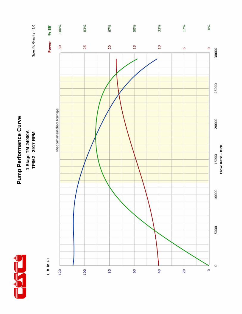
Pu
mp
Per
form
ance
Cu
rve
Sp
ecif
ic G
ravi
ty =
1.0
1 S
tag
e T
M-2
4000
A
TP
862
- 29
17 R
PM
Li
ft in
FT
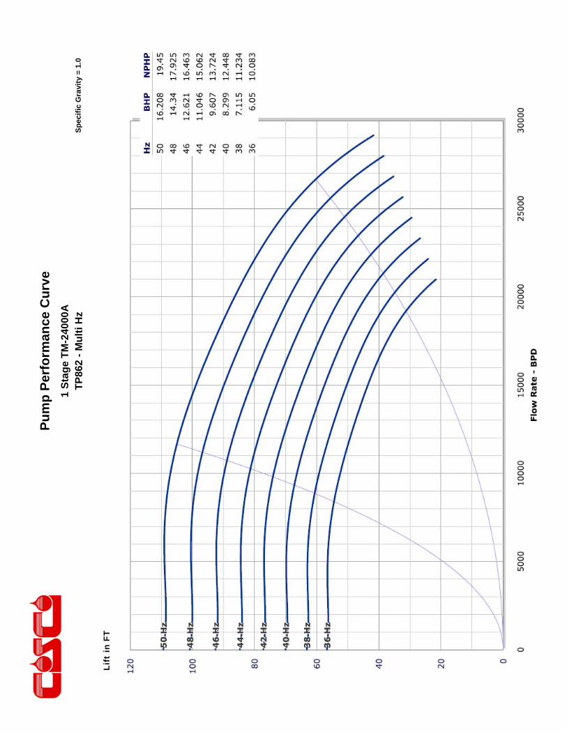
Pu
mp
Per
form
ance
Cu
rve
Sp
ecif
ic G
ravi
ty =
1.0
1 S
tag
e T
M-2
4000
A
TP
862
- M
ult
i Hz
Li
ft in
FT

This engineering performance curve represents nominal performance based on actual mul ‐stage tes ng and cer fica on. All pumps supplied by COSCO will be tested and cer fied to perform within the acceptable limits for head, horsepower, and efficiency as defined in the “API RECOMMENDED PRACTICE(11S2) FOR ELECTRIC SUBMERSIBLE PUMP TESTING”.
COSCO 862 Series Pumps
ENGINEERING DATA
Housing Diameter 8.62 inches Maximum Staging: Shaft
Minimum Casing Size 10 3/4 Inches Shaft Type
Fluid Specific Gravity for Pump Curves 1.0 50 Hz 60 Hz
Rotational Direction CCW Standard Shaft 31 22
Shaft Details HSS 51 36
Shaft Diameter 1 3/16 1.1875 Inches Housing Pressure Limit 2000 PSI
Shaft Area 1.107 Sq. Inches Maximum Staging: Thrust Bearings (250F BHT)
Shaft Limits Bearing Type
No of Stages @
Shaft Limit in HP at: 50 Hz 60 Hz 50 Hz 60 Hz
Standard Shaft Limit 531 637 Standard Bearing
High Strength (HSS) 849 1019 Hi Load Bearing
No of Stages @

COSCO 862 Series Pumps
TM24000B / 862 Series Pump >>Minimum Casing Size 10 3/4 Inches Maximum Bottom Hole Temperature: 250 F
STANDARD PUMP
COMPRESSION COMPRESSION AR
Part Number Stages
Part Number Stages Housings
Length (ft.)
Weight (lb.)
31860121 3 31880121 3 3 3.3 528
31860122 4 31880122 4 4 3.9 587
31860123 5 31880123 5 5 4.5 662
31860124 6 31880124 6 6 5.1 729
31860125 7 31880125 7 7 5.7 789
31860126 8 31880126 8 8 6.3 863
31860127 9 31880127 9 9 6.9 931
31860128 10 31880128 10 10 7.5 991
31860129 11 31880129 11 11 8.1 1058
31860130 12 31880130 12 12 8.7 1126
31860131 13 31880131 13 13 9.3 1193
31860132 14 31880132 14 14 9.9 1260
31860133 15 31880133 15 15 10.6 1327
31860134 16 31880134 16 16 11.2 1395
31860135 17 31880135 17 17 11.8 1466
31860136 18 31880136 18 18 12.4 1533
31860137 19 31880137 19 19 13 1596
31860138 20 31880138 20 20 13.6 1664
31860139 21 31880139 21 21 14.2 1734
31860140 22 31880140 22 22 14.8 1801
31860141 23 31880141 23 23 15.4 1866
31860142 24 31880142 24 24 16 1933
31860143 25 31880143 25 25 16.6 2003
31860144 26 31880144 26 26 17.2 2071
31860145 27 31880145 27 27 17.8 2138
31860146 28 31880146 28 28 18.4 2202
31860147 29 31880147 29 29 19 2272
31860148 30 31880148 30 30 19.6 2339
31860149 31 31880149 31 31 20.2 2407
31860150 32 31880150 32 32 20.8 2474
Pump Outside Diameter: 8.62 inches Standard Features: Carbon Steel Head, Base and Housing. Monel K500 Shaft. Housing also available in 13 Chrome.
Heads and Bases also available in SST410 or 316L Stainless Steel.
All pumps are in Center Tandem Configuration. To calculate shipping length, add shipping caps (0.06 feet upper / 0.30 feet lower) to component length.
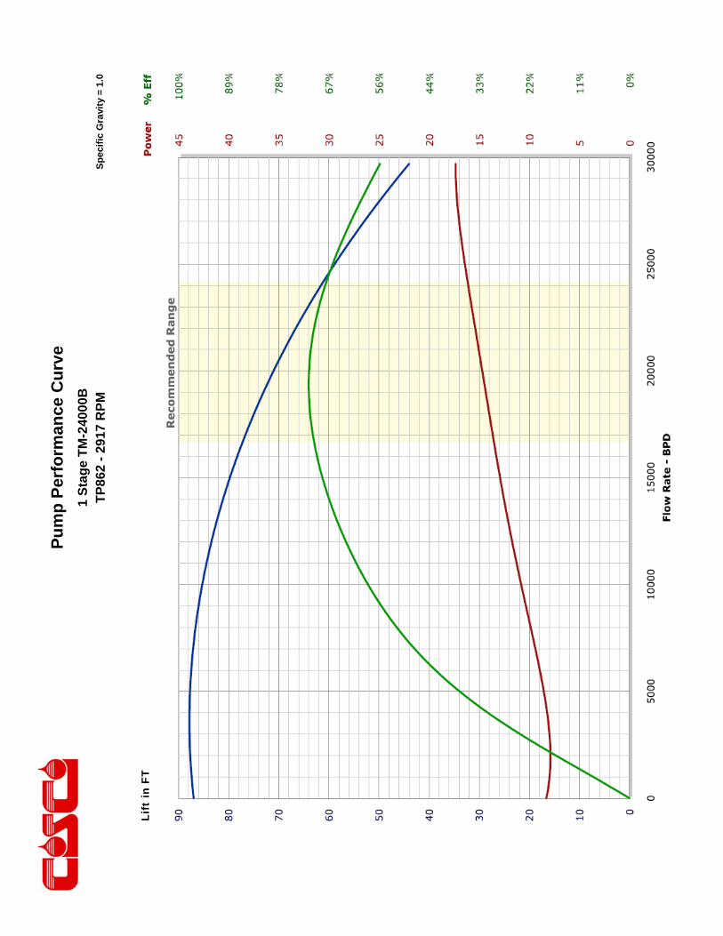
Pu
mp
Per
form
ance
Cu
rve
Sp
ecif
ic G
ravi
ty =
1.0
1 S
tag
e T
M-2
4000
B
TP
862
- 29
17 R
PM
Li
ft in
FT

Pu
mp
Per
form
ance
Cu
rve
Sp
ecif
ic G
ravi
ty =
1.0
1 S
tag
e T
M-2
4000
B
TP
862
- M
ult
i Hz
Li
ft in
FT
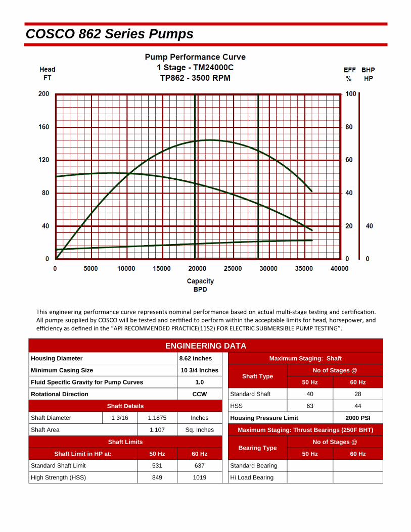
This engineering performance curve represents nominal performance based on actual mul ‐stage tes ng and cer fica on. All pumps supplied by COSCO will be tested and cer fied to perform within the acceptable limits for head, horsepower, and efficiency as defined in the “API RECOMMENDED PRACTICE(11S2) FOR ELECTRIC SUBMERSIBLE PUMP TESTING”.
COSCO 862 Series Pumps
ENGINEERING DATA
Housing Diameter 8.62 inches Maximum Staging: Shaft
Minimum Casing Size 10 3/4 Inches Shaft Type
Fluid Specific Gravity for Pump Curves 1.0 50 Hz 60 Hz
Rotational Direction CCW Standard Shaft 40 28
Shaft Details HSS 63 44
Shaft Diameter 1 3/16 1.1875 Inches Housing Pressure Limit 2000 PSI
Shaft Area 1.107 Sq. Inches Maximum Staging: Thrust Bearings (250F BHT)
Shaft Limits Bearing Type
No of Stages @
Shaft Limit in HP at: 50 Hz 60 Hz 50 Hz 60 Hz
Standard Shaft Limit 531 637 Standard Bearing
High Strength (HSS) 849 1019 Hi Load Bearing
No of Stages @

COSCO 862 Series Pumps
TM24000C / 862 Series Pump >>Minimum Casing Size 10 3/4 Inches Maximum Bottom Hole Temperature: 250 F
STANDARD PUMP
COMPRESSION COMPRESSION AR
Part Number Stages
Part Number Stages Housings
Length (ft.)
Weight (lb.)
31860151 3 31880151 3 3 3.3 528
31860152 4 31880152 4 4 3.9 587
31860153 5 31880153 5 5 4.5 662
31860154 6 31880154 6 6 5.1 729
31860155 7 31880155 7 7 5.7 789
31860156 8 31880156 8 8 6.3 863
31860157 9 31880157 9 9 6.9 931
31860158 10 31880158 10 10 7.5 991
31860159 11 31880159 11 11 8.1 1058
31860160 12 31880160 12 12 8.7 1126
31860161 13 31880161 13 13 9.3 1193
31860162 14 31880162 14 14 9.9 1260
31860163 15 31880163 15 15 10.6 1327
31860164 16 31880164 16 16 11.2 1395
31860165 17 31880165 17 17 11.8 1466
31860166 18 31880166 18 18 12.4 1533
31860167 19 31880167 19 19 13 1596
31860168 20 31880168 20 20 13.6 1664
31860169 21 31880169 21 21 14.2 1734
31860170 22 31880170 22 22 14.8 1801
31860171 23 31880171 23 23 15.4 1866
31860172 24 31880172 24 24 16 1933
31860173 25 31880173 25 25 16.6 2003
31860174 26 31880174 26 26 17.2 2071
31860175 27 31880175 27 27 17.8 2138
31860176 28 31880176 28 28 18.4 2202
31860177 29 31880177 29 29 19 2272
31860178 30 31880178 30 30 19.6 2339
31860179 31 31880179 31 31 20.2 2407
31860180 32 31880180 32 32 20.8 2474
Pump Outside Diameter: 8.62 inches Standard Features: Carbon Steel Head, Base and Housing. Monel K500 Shaft. Housing also available in 13 Chrome.
Heads and Bases also available in SST410 or 316L Stainless Steel.
All pumps are in Center Tandem Configuration. To calculate shipping length, add shipping caps (0.06 feet upper / 0.30 feet lower) to component length.
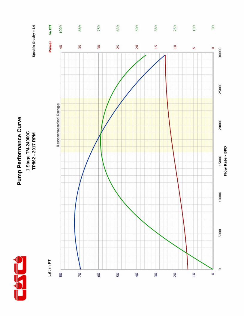
Pu
mp
Per
form
ance
Cu
rve
Sp
ecif
ic G
ravi
ty =
1.0
1 S
tag
e T
M-2
4000
C
TP
862
- 29
17 R
PM
Li
ft in
FT
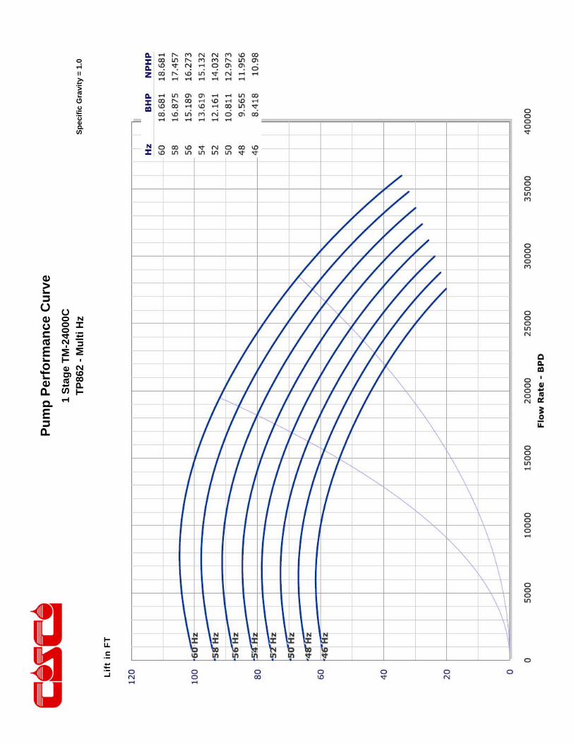
Pu
mp
Per
form
ance
Cu
rve
Sp
ecif
ic G
ravi
ty =
1.0
1 S
tag
e T
M-2
4000
C
TP
862
- M
ult
i Hz
Li
ft in
FT
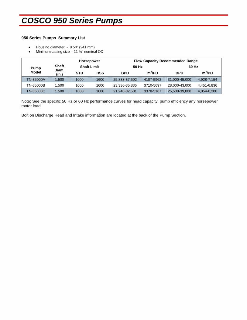
COSCO 950 Series Pumps 950 Series Pumps Summary List
Housing diameter - 9.50” (241 mm) Minimum casing size – 11 ¾” nominal OD
Horsepower Flow Capacity Recommended Range
Pump Model
Shaft Diam. (in.)
Shaft Limit 50 Hz 60 Hz
STD HSS BPD m3/PD BPD m3/PD
TN-35000A 1.500 1000 1600 25,833-37,502 4107-5962 31,000-45,000 4,928-7,154
TN-35000B 1.500 1000 1600 23,336-35,835 3710-5697 28,000-43,000 4,451-6,836
TN-35000C 1.500 1000 1600 21,248-32,501 3378-5167 25,500-39,000 4,054-6,200
Note: See the specific 50 Hz or 60 Hz performance curves for head capacity, pump efficiency any horsepower motor load. Bolt on Discharge Head and Intake information are located at the back of the Pump Section.

This engineering performance curve represents nominal performance based on actual mul ‐stage tes ng and cer fica on. All pumps supplied by COSCO will be tested and cer fied to perform within the acceptable limits for head, horsepower, and efficiency as defined in the “API RECOMMENDED PRACTICE(11S2) FOR ELECTRIC SUBMERSIBLE PUMP TESTING”.
COSCO 950 Series Pumps
ENGINEERING DATA
Housing Diameter 9.5 inches Maximum Staging: Shaft
Minimum Casing Size 11 3/4 Inch Shaft Type
Fluid Specific Gravity for Pump Curves 1.0 50 Hz 60 Hz
Rotational Direction CCW Standard Shaft 24 17
Shaft Details HSS 39 27
Shaft Diameter 1 1/2 1.500 Inches Housing Pressure Limit 2300 PSI
Shaft Area 1.767 Sq. Inches Maximum Staging: Thrust Bearings (250F BHT)
Shaft Limits Bearing Type
No of Stages @
Shaft Limit in HP at: 50 Hz 60 Hz 50 Hz 60 Hz
Standard Shaft Limit 833 1000 Standard Bearing
High Strength (HSS) 1333 1600 Hi Load Bearing
No of Stages @
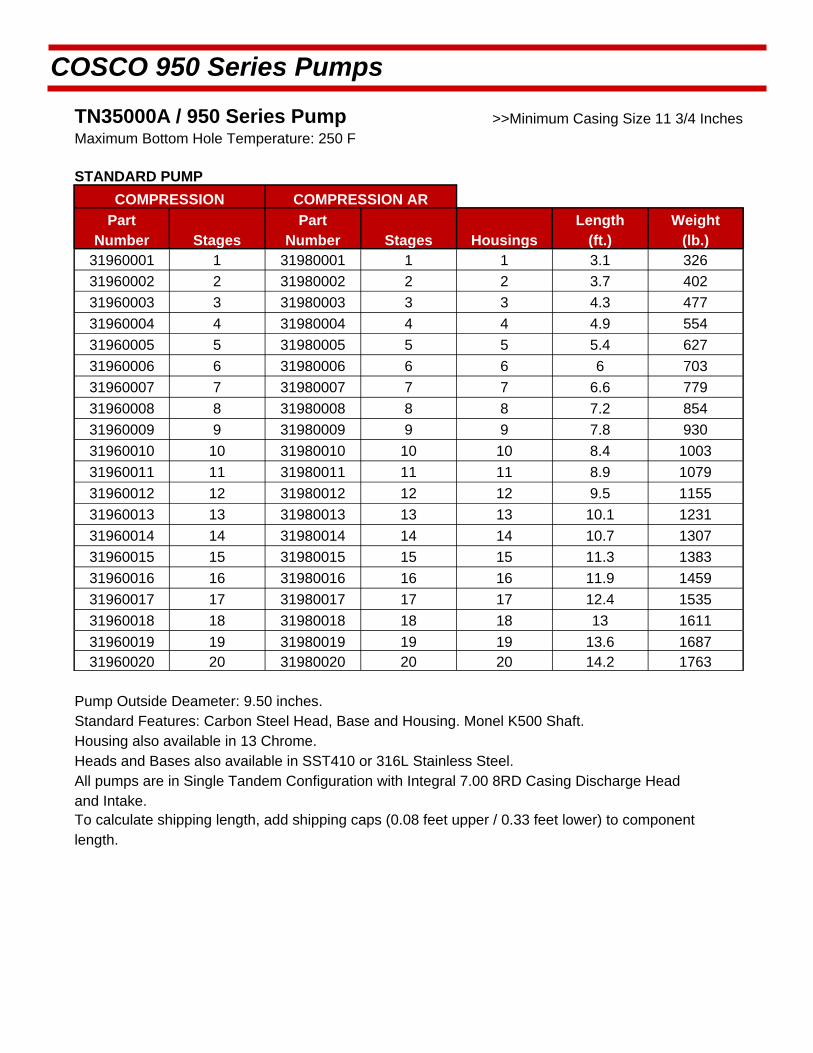
COSCO 950 Series Pumps
TN35000A / 950 Series Pump >>Minimum Casing Size 11 3/4 Inches Maximum Bottom Hole Temperature: 250 F
STANDARD PUMP
COMPRESSION COMPRESSION AR
Part Number Stages
Part Number Stages Housings
Length (ft.)
Weight (lb.)
31960001 1 31980001 1 1 3.1 326
31960002 2 31980002 2 2 3.7 402
31960003 3 31980003 3 3 4.3 477
31960004 4 31980004 4 4 4.9 554
31960005 5 31980005 5 5 5.4 627
31960006 6 31980006 6 6 6 703
31960007 7 31980007 7 7 6.6 779
31960008 8 31980008 8 8 7.2 854
31960009 9 31980009 9 9 7.8 930
31960010 10 31980010 10 10 8.4 1003
31960011 11 31980011 11 11 8.9 1079
31960012 12 31980012 12 12 9.5 1155
31960013 13 31980013 13 13 10.1 1231
31960014 14 31980014 14 14 10.7 1307
31960015 15 31980015 15 15 11.3 1383
31960016 16 31980016 16 16 11.9 1459
31960017 17 31980017 17 17 12.4 1535
31960018 18 31980018 18 18 13 1611
31960019 19 31980019 19 19 13.6 1687 31960020 20 31980020 20 20 14.2 1763
Standard Features: Carbon Steel Head, Base and Housing. Monel K500 Shaft. Housing also available in 13 Chrome.
Heads and Bases also available in SST410 or 316L Stainless Steel.
All pumps are in Single Tandem Configuration with Integral 7.00 8RD Casing Discharge Head and Intake. To calculate shipping length, add shipping caps (0.08 feet upper / 0.33 feet lower) to component length.
Pump Outside Deameter: 9.50 inches.
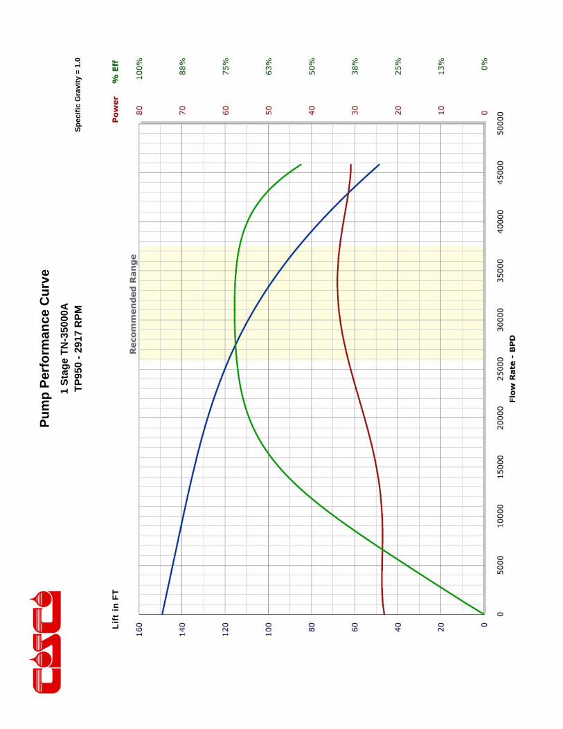
Pu
mp
Per
form
ance
Cu
rve
Sp
ecif
ic G
ravi
ty =
1.0
1 S
tag
e T
N-3
5000
A
TP
950
- 29
17 R
PM
Li
ft in
FT

Pu
mp
Per
form
ance
Cu
rve
Sp
ecif
ic G
ravi
ty =
1.0
1 S
tag
e T
N-3
5000
A
TP
950
- M
ult
i Hz
Li
ft in
FT

This engineering performance curve represents nominal performance based on actual mul ‐stage tes ng and cer fica on. All pumps supplied by COSCO will be tested and cer fied to perform within the acceptable limits for head, horsepower, and efficiency as defined in the “API RECOMMENDED PRACTICE(11S2) FOR ELECTRIC SUBMERSIBLE PUMP TESTING”.
COSCO 950 Series Pumps
ENGINEERING DATA
Housing Diameter 9.5 inches Maximum Staging: Shaft
Minimum Casing Size 11 3/4 Inch Shaft Type
Fluid Specific Gravity for Pump Curves 1.0 50 Hz 60 Hz
Rotational Direction CCW Standard Shaft 33 23
Shaft Details HSS 52 36
Shaft Diameter 1 1/2 1.500 Inches Housing Pressure Limit 2300 PSI
Shaft Area 1.767 Sq. Inches Maximum Staging: Thrust Bearings (250F BHT)
Shaft Limits Bearing Type
No of Stages @
Shaft Limit in HP at: 50 Hz 60 Hz 50 Hz 60 Hz
Standard Shaft Limit 833 1000 Standard Bearing
High Strength (HSS) 1333 1600 Hi Load Bearing
No of Stages @
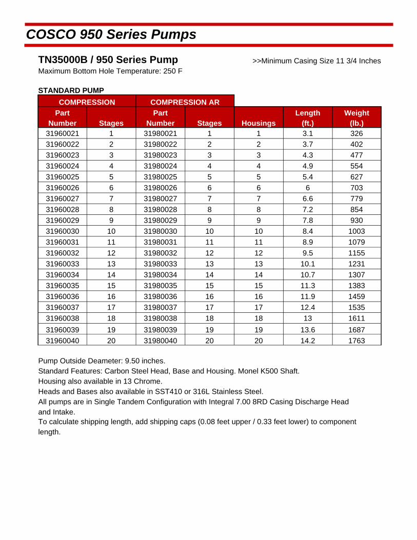
COSCO 950 Series Pumps
TN35000B / 950 Series Pump >>Minimum Casing Size 11 3/4 Inches Maximum Bottom Hole Temperature: 250 F
STANDARD PUMP
COMPRESSION COMPRESSION AR
Part Number Stages
Part Number Stages Housings
Length (ft.)
Weight (lb.)
31960021 1 31980021 1 1 3.1 326
31960022 2 31980022 2 2 3.7 402
31960023 3 31980023 3 3 4.3 477
31960024 4 31980024 4 4 4.9 554
31960025 5 31980025 5 5 5.4 627
31960026 6 31980026 6 6 6 703
31960027 7 31980027 7 7 6.6 779
31960028 8 31980028 8 8 7.2 854
31960029 9 31980029 9 9 7.8 930
31960030 10 31980030 10 10 8.4 1003
31960031 11 31980031 11 11 8.9 1079
31960032 12 31980032 12 12 9.5 1155
31960033 13 31980033 13 13 10.1 1231
31960034 14 31980034 14 14 10.7 1307
31960035 15 31980035 15 15 11.3 1383
31960036 16 31980036 16 16 11.9 1459
31960037 17 31980037 17 17 12.4 1535
31960038 18 31980038 18 18 13 1611
31960039 19 31980039 19 19 13.6 1687
31960040 20 31980040 20 20 14.2 1763
Standard Features: Carbon Steel Head, Base and Housing. Monel K500 Shaft. Housing also available in 13 Chrome.
Heads and Bases also available in SST410 or 316L Stainless Steel.
All pumps are in Single Tandem Configuration with Integral 7.00 8RD Casing Discharge Head and Intake. To calculate shipping length, add shipping caps (0.08 feet upper / 0.33 feet lower) to component length.
Pump Outside Deameter: 9.50 inches.
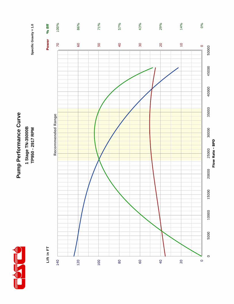
Pu
mp
Per
form
ance
Cu
rve
Sp
ecif
ic G
ravi
ty =
1.0
1 S
tag
e T
N-3
5000
B
TP
950
- 29
17 R
PM
Li
ft in
FT
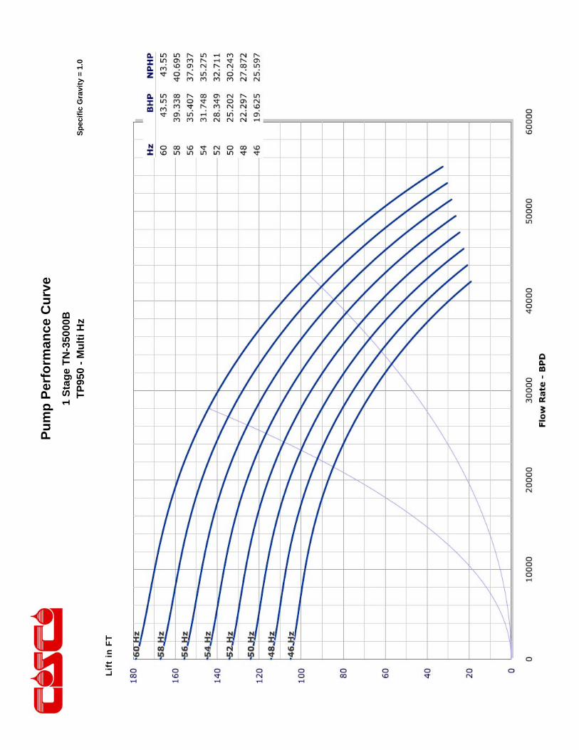
Pu
mp
Per
form
ance
Cu
rve
Sp
ecif
ic G
ravi
ty =
1.0
1 S
tag
e T
N-3
5000
B
TP
950
- M
ult
i Hz
Li
ft in
FT
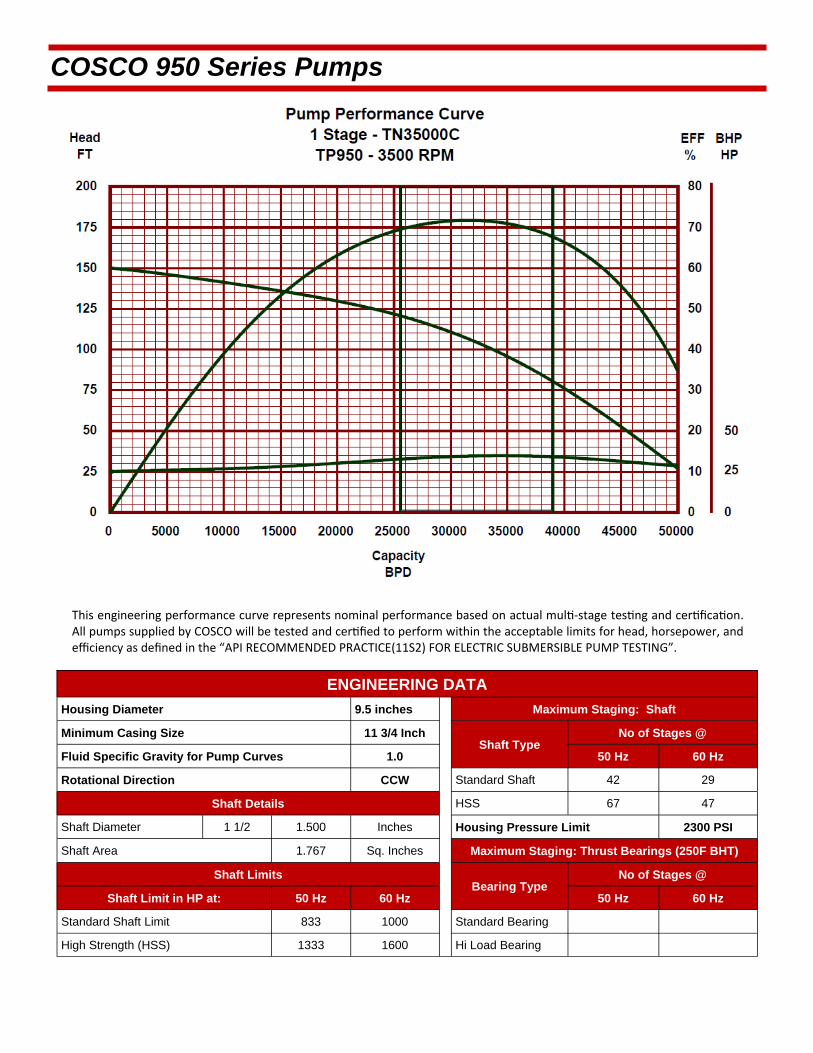
This engineering performance curve represents nominal performance based on actual mul ‐stage tes ng and cer fica on. All pumps supplied by COSCO will be tested and cer fied to perform within the acceptable limits for head, horsepower, and efficiency as defined in the “API RECOMMENDED PRACTICE(11S2) FOR ELECTRIC SUBMERSIBLE PUMP TESTING”.
COSCO 950 Series Pumps
ENGINEERING DATA
Housing Diameter 9.5 inches Maximum Staging: Shaft
Minimum Casing Size 11 3/4 Inch Shaft Type
Fluid Specific Gravity for Pump Curves 1.0 50 Hz 60 Hz
Rotational Direction CCW Standard Shaft 42 29
Shaft Details HSS 67 47
Shaft Diameter 1 1/2 1.500 Inches Housing Pressure Limit 2300 PSI
Shaft Area 1.767 Sq. Inches Maximum Staging: Thrust Bearings (250F BHT)
Shaft Limits Bearing Type
No of Stages @
Shaft Limit in HP at: 50 Hz 60 Hz 50 Hz 60 Hz
Standard Shaft Limit 833 1000 Standard Bearing
High Strength (HSS) 1333 1600 Hi Load Bearing
No of Stages @

COSCO 950 Series Pumps
TN35000C / 950 Series Pump >>Minimum Casing Size 11 3/4 Inches Maximum Bottom Hole Temperature: 250 F
STANDARD PUMP
COMPRESSION COMPRESSION AR
Part Number Stages
Part Number Stages Housings
Length (ft.)
Weight (lb.)
31960041 1 31980041 1 1 3.1 326
31960042 2 31980042 2 2 3.7 402
31960043 3 31980043 3 3 4.3 477
31960044 4 31980044 4 4 4.9 554
31960045 5 31980045 5 5 5.4 627
31960046 6 31980046 6 6 6 703
31960047 7 31980047 7 7 6.6 779
31960048 8 31980048 8 8 7.2 854
31960049 9 31980049 9 9 7.8 930
31960050 10 31980050 10 10 8.4 1003
31960051 11 31980051 11 11 8.9 1079
31960052 12 31980052 12 12 9.5 1155
31960053 13 31980053 13 13 10.1 1231
31960054 14 31980054 14 14 10.7 1307
31960055 15 31980055 15 15 11.3 1383
31960056 16 31980056 16 16 11.9 1459
31960057 17 31980057 17 17 12.4 1535
31960058 18 31980058 18 18 13 1611
31960059 19 31980059 19 19 13.6 1687
31960060 20 31980060 20 20 14.2 1763
Standard Features: Carbon Steel Head, Base and Housing. Monel K500 Shaft. Housing also available in 13 Chrome.
Heads and Bases also available in SST410 or 316L Stainless Steel.
All pumps are in Single Tandem Configuration with Integral 7.00 8RD Casing Discharge Head and Intake. To calculate shipping length, add shipping caps (0.08 feet upper / 0.33 feet lower) to component length.
Pump Outside Deameter: 9.50 inches.
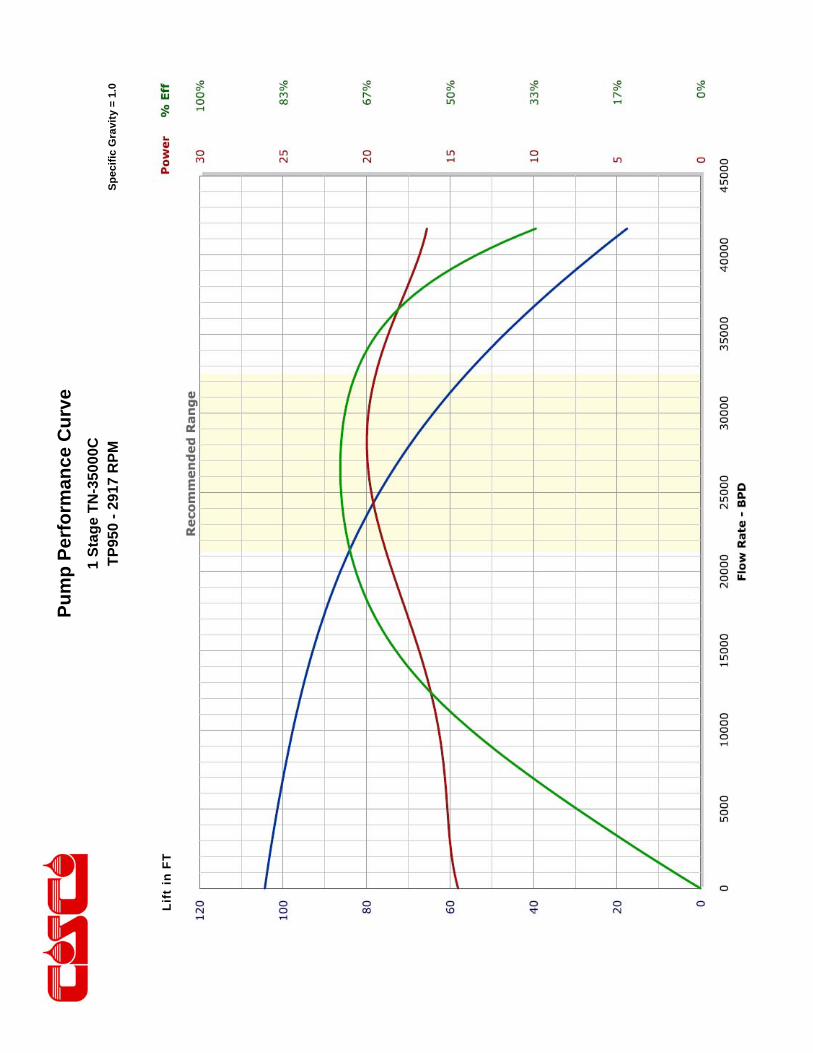
Pu
mp
Per
form
ance
Cu
rve
Sp
ecif
ic G
ravi
ty =
1.0
1 S
tag
e T
N-3
5000
C
TP
950
- 29
17 R
PM
Li
ft in
FT
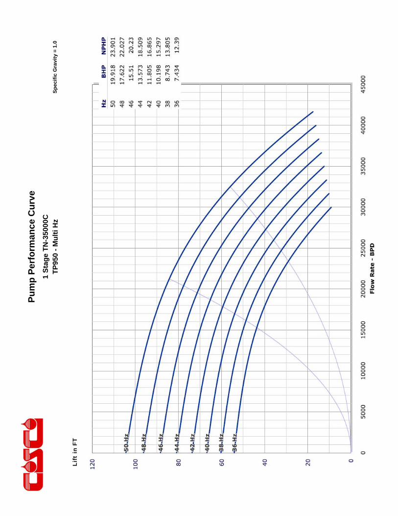
Pu
mp
Per
form
ance
Cu
rve
Sp
ecif
ic G
ravi
ty =
1.0
1 S
tag
e T
N-3
5000
C
TP
950
- M
ult
i Hz
Li
ft in
FT
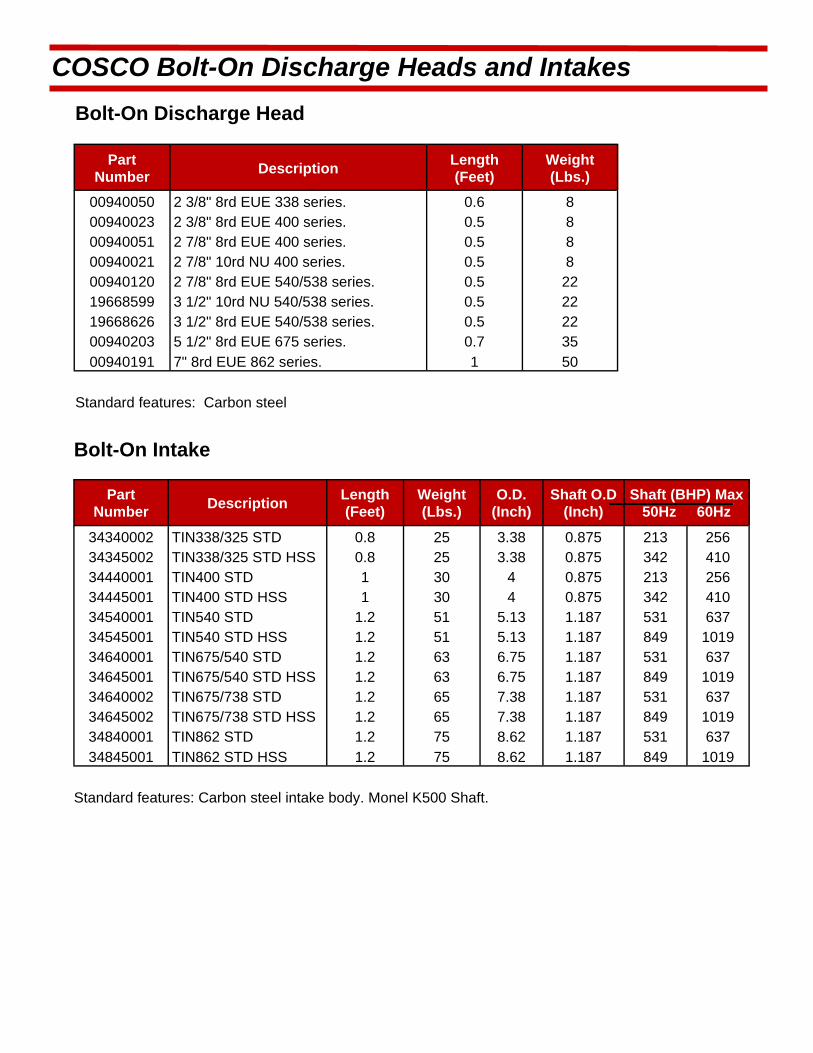
COSCO Bolt-On Discharge Heads and Intakes
Bolt-On Discharge Head
Part Number
Description Length (Feet)
Weight (Lbs.)
00940050 2 3/8" 8rd EUE 338 series. 0.6 8 00940023 2 3/8" 8rd EUE 400 series. 0.5 8 00940051 2 7/8" 8rd EUE 400 series. 0.5 8 00940021 2 7/8" 10rd NU 400 series. 0.5 8 00940120 2 7/8" 8rd EUE 540/538 series. 0.5 22 19668599 3 1/2" 10rd NU 540/538 series. 0.5 22 19668626 3 1/2" 8rd EUE 540/538 series. 0.5 22 00940203 5 1/2" 8rd EUE 675 series. 0.7 35
00940191 7" 8rd EUE 862 series. 1 50
Standard features: Carbon steel
Bolt-On Intake
Part Number
Description Length (Feet)
Weight (Lbs.)
O.D. (Inch)
Shaft O.D (Inch)
Shaft (BHP) Max 50Hz 60Hz
34340002 TIN338/325 STD 0.8 25 3.38 0.875 213 256 34345002 TIN338/325 STD HSS 0.8 25 3.38 0.875 342 410 34440001 TIN400 STD 1 30 4 0.875 213 256 34445001 TIN400 STD HSS 1 30 4 0.875 342 410 34540001 TIN540 STD 1.2 51 5.13 1.187 531 637 34545001 TIN540 STD HSS 1.2 51 5.13 1.187 849 1019 34640001 TIN675/540 STD 1.2 63 6.75 1.187 531 637 34645001 TIN675/540 STD HSS 1.2 63 6.75 1.187 849 1019 34640002 TIN675/738 STD 1.2 65 7.38 1.187 531 637 34645002 TIN675/738 STD HSS 1.2 65 7.38 1.187 849 1019 34840001 TIN862 STD 1.2 75 8.62 1.187 531 637
34845001 TIN862 STD HSS 1.2 75 8.62 1.187 849 1019
Standard features: Carbon steel intake body. Monel K500 Shaft.

COSCO Rotary and Vortex Gas Separators
Rotary Gas Separator
Part Number
Description Length (Feet)
Weight (Lbs.)
O.D. (Inch)
Shaft O.D (Inch)
Shaft (BHP) Max 50Hz 60Hz
34330003 RGS TS338/325 2B STD 2.5 40 3.38 0.875 213 256 34335003 RGS TS338/325 2B STD HSS 2.5 40 3.38 0.875 342 410 34330004 RGS TS338/325 3B STD 2.8 45 3.38 0.875 213 256 34335004 RGS TS338/325 3B STD HSS 2.8 45 3.38 0.875 342 410 34430001 RGS TS400 2B STD 2.6 55 4.00 0.875 213 256 34435001 RGS TS400 2B STD HSS 2.6 55 4.00 0.875 342 410 34430002 RGS TS400 3B STD 3 65 4.00 0.875 213 256 34435002 RGS TS400 3B STD HSS 3 65 4.00 0.875 342 410 34430003 RGS TS400 UT STD 2.3 50 4.00 0.875 213 256 34435003 RGS TS400 UT STD HSS 2.3 50 4.00 0.875 342 410 34530002 RGS TS540 3B STD 3.2 150 5.13 1.187 531 637 34535002 RGS TS540 3B STD HSS 3.2 150 5.13 1.187 849 1019 34530003 RGS TS540 UT STD 2.6 120 5.13 1.187 531 637
34535003 RGS TS540 UT STD HSS 2.6 120 5.13 1.187 849 1019
Standard features: Carbon steel Head, Base and Housing. Monel K500 Shaft.
High Strength Shaft (HSS): Inconel 718 available upon request.
Corrosion Resistant features (CR): Stainless steel Head, Base and Housing. Monel K500 Shaft.
Vortex Gas Separator
Part Number
Description Length (Feet)
Weight (Lbs.)
O.D. (Inch)
Shaft O.D (Inch)
Shaft (BHP) Max 50Hz 60Hz
04450001 VGS TS400 STD 2.6 55 4 0.875 213 256 04455001 VGS TS400 STD HSS 2.6 55 4 0.875 342 410 04450002 VGS TS400 UT STD 2.3 50 4 0.875 213 256 04455002 VGS TS400 UT STD HSS 2.3 50 4 0.875 342 410 04550001 VGS TS538 STD 3.6 140 5.38 1.187 531 637 04555001 VGS TS538 STD HSS 3.6 140 5.38 1.187 849 1019 04550002 VGS TS538 UT STD 3.3 135 5.38 1.187 531 637 04555002 VGS TS538 UT STD HSS 3.3 135 5.38 1.187 849 1019
Standard features: Carbon steel Head, Base and Housing. Monel K500 Shaft.
Corrosion Resistant features (CR): Stainless steel Head, Base and Housing. Monel K500 Shaft. High Strength Shaft (HSS): Inconel 718 available upon request.

COSCO Gas Pro Intake Pump
GasPro Intake Pump
Part Number Description
Flow Rate (BPD)
Length (Feet)
Weight (Lbs.)
O.D. (Inch)
Shaft O.D (Inch)
Shaft (BHP) Max 50Hz 60Hz Config.
04460001 GasPro D50 500 - 2000 6.3 134 4 0.688 125 200 FL 04460002 GasPro D175 2000 - 6000 6.3 134 4 0.875 213 256 COMP 04460003 GasPro D175 2000 - 6000 6.3 134 4 0.875 213 256 COMP AR 04560001 GasPro G125 2000 - 4000 6.3 271 5.13 1 375 600 FL 04560002 GasPro E200 4000 - 10000 7 284 5.38 1 375 600 COMP 04560003 GasPro E200 4000 - 10000 7 284 5.38 1 375 600 COMP AR
The GasPro Intake Pumps are designed for gassy wells with high gas oil ratio (GOR) and low intake pressure. They are typically installed below production pumps and/or above rotory or vortex gas separators. By reconditioning the liquid gas mixture into a single phase fluid before entering the production pump, production is significantly improved by preventing degradation of pump performance and gas locking. Compression and abrasive resistant construction improve reliability in wells containing abrasives.

COSCO 375 Series Motors
TM375 Series Motors
Maximum operating temperature = 300F
50 Hz 60 Hz Length Weight Type
Part HP Volt Amp HP Volt Amp (ft.) (lbs.) Number
6.25 342 14 7.5 410 14 6.4 208 UT 32333001
8.75 325 20.5 10.5 390 20.5 8.3 270 UT 32333002
12.5 262 35.5 15 315 35.5 11.0 361 UT 32333003
11.1 361 CT 32333004
12.5 333 28 15 400 28 11.0 361 UT 32333005
11.1 361 CT 32333006
16.25 323 38 19.5 387 38 13.8 456 UT 32333007
13.9 456 CT 32333008
16.25 525 23 19.5 630 23 13.8 456 UT 32333009
13.9 456 CT 32333010
18.75 275 51.5 22.5 330 51.5 15.7 514 UT 32333011
15.8 514 CT 32333012
18.75 367 38.5 22.5 440 38.5 15.7 514 UT 32333013
15.8 514 CT 32333014
18.75 608 23 22.5 730 23 15.7 514 UT 32333015
15.8 514 CT 32333016
21.25 308 51 25.5 370 51 17.6 660 UT 32333017
17.7 660 CT 32333018
21.25 417 37 25.5 500 37 17.6 660 UT 32333019
17.7 660 CT 32333020
21.25 525 30 25.5 630 30 17.6 660 UT 32333021
17.7 660 CT 32333022
UT - Upper Tandem
CT - Center Tandem
Universal Motor Base
Description Length
(ft.) Weight
(lb.) Part
Number
Universal Motor Base, 375 Series 0.5 15.0 00910312
Bolt-on Motor Head
Description Length
(ft.) Weight
(lb.) Part
Number
Bolt-on Motor Head, 375 Series 1.5 35.2 00902460
>> Minimum casing size 4 1/2 inches
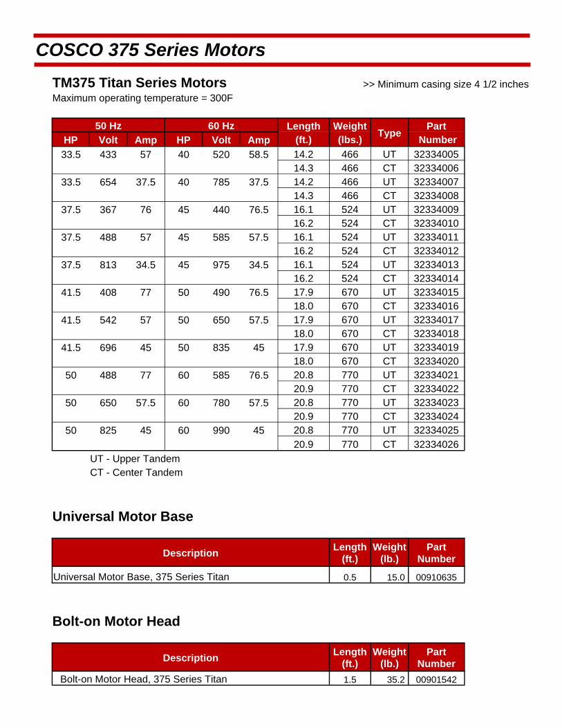
COSCO 375 Series Motors
TM375 Titan Series Motors >> Minimum casing size 4 1/2 inches Maximum operating temperature = 300F
50 Hz 60 Hz Length Weight Type
Part HP Volt Amp HP Volt Amp (ft.) (lbs.) Number
33.5 433 57 40 520 58.5 14.2 466 UT 32334005
14.3 466 CT 32334006
33.5 654 37.5 40 785 37.5 14.2 466 UT 32334007
14.3 466 CT 32334008
37.5 367 76 45 440 76.5 16.1 524 UT 32334009
16.2 524 CT 32334010
37.5 488 57 45 585 57.5 16.1 524 UT 32334011
16.2 524 CT 32334012
37.5 813 34.5 45 975 34.5 16.1 524 UT 32334013
16.2 524 CT 32334014
41.5 408 77 50 490 76.5 17.9 670 UT 32334015
18.0 670 CT 32334016
41.5 542 57 50 650 57.5 17.9 670 UT 32334017
18.0 670 CT 32334018
41.5 696 45 50 835 45 17.9 670 UT 32334019
18.0 670 CT 32334020
50 488 77 60 585 76.5 20.8 770 UT 32334021
20.9 770 CT 32334022
50 650 57.5 60 780 57.5 20.8 770 UT 32334023
20.9 770 CT 32334024
50 825 45 60 990 45 20.8 770 UT 32334025
20.9 770 CT 32334026
UT - Upper Tandem
CT - Center Tandem
Universal Motor Base
Description Length
(ft.) Weight
(lb.) Part
Number
Universal Motor Base, 375 Series Titan 0.5 15.0 00910635
Bolt-on Motor Head
Description Length
(ft.) Weight
(lb.) Part
Number
1.5 35.2 00901542 Bolt-on Motor Head, 375 Series Titan

COSCO 456 Series Motors
TM456 Series Motors
Maximum operating temperature = 300F
50 Hz 60 Hz Length Weight Type
Part HP Volt Amp HP Volt Amp (ft.) (lbs.) Number 8.5 363 16 10 435 16 5.1 240 ST 32434001
4.1 200 UT 32434002 12.5 363 23 15 435 23 6.3 288 ST 32434003
5.3 248 UT 32434004 12.5 509 16 15 610 16 6.3 288 ST 32434005
5.3 248 UT 32434006 16.5 375 28.5 20 450 28.5 7.5 345 ST 32434007
6.5 305 UT 32434008 16.5 625 17 20 750 17 7.5 345 ST 32434009
6.5 305 UT 32434010 21 340 39 25 410 39 8.7 402 ST 32434011 7.7 362 UT 32434012
21 575 22 25 690 22 8.7 402 ST 32434013 7.7 362 UT 32434014
21 675 20 25 810 20 8.7 402 ST 32434015 7.7 362 UT 32434016
25 355 44.5 30 425 44.5 9.9 482 ST 32434017 8.9 422 UT 32434018
25 625 25.5 30 750 25.5 9.9 482 ST 32434019 8.9 422 UT 32434020
29.5 333 55 35 400 55 11.1 520 ST 32434021 10.1 480 UT 32434022
29.5 563 33 35 675 33 11.1 520 ST 32434023 10.1 480 UT 32434024
29.5 654 28 35 750 28 11.1 520 ST 32434025 10.1 480 UT 32434026
33.5 358 59 40 430 59 12.3 578 ST 32434027 11.3 538 UT 32434028
33.5 642 33 40 770 33 12.3 578 ST 32434029 11.3 538 UT 32434030
33.5 733 29 40 880 29 12.3 578 ST 32434031 11.3 538 UT 32434032
33.5 1080 20 40 1295 20 12.3 578 ST 32434033 11.3 538 UT 32434034
41.5 563 47 50 675 47 14.7 695 ST 32434035 13.7 655 UT 32434036
41.5 679 39 50 815 39 14.7 695 ST 32434037 13.7 655 UT 32434038
41.5 796 33 50 955 33 14.7 695 ST 32434039 13.7 655 UT 32434040
41.5 892 31 50 1070 31 14.7 695 ST 32434041 13.7 655 UT 32434042
41.5 1007 27 50 1210 27 14.7 695 ST 32434043 13.7 655 UT 32434044
50 533 59 60 640 59 17.5 700 ST 32434045 16.5 660 UT 32434046
50 621 52 60 745 52 17.5 700 ST 32434047 16.5 660 UT 32434048
50 675 47 60 810 47 17.5 700 ST 32434049 16.5 660 UT 32434050
ST - Single Tandem UT - Upper Tandem CT - Center Tandem
>> Minimum casing size 5 1/2 inches
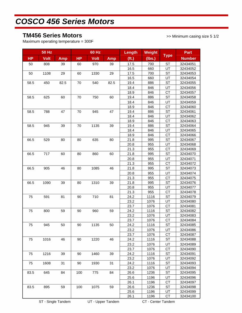
COSCO 456 Series Motors
TM456 Series Motors
Maximum operating temperature = 300F
50 Hz 60 Hz Length Weight Type
Part HP Volt Amp HP Volt Amp (ft.) (lbs.) Number 50 808 39 60 970 39 17.5 700 ST 32434051 16.5 660 UT 32434052
50 1108 29 60 1330 29 17.5 700 ST 32434053 16.5 660 UT 32434054
58.5 450 82.5 70 540 82.5 19.4 886 ST 32434055
18.4 846 UT 32434056 18.9 846 CT 32434057
58.5 625 60 70 750 60 19.4 886 ST 32434058
18.4 846 UT 32434059 18.9 846 CT 32434060
58.5 788 47 70 945 47 19.4 886 ST 32434061 18.4 846 UT 32434062 18.9 846 CT 32434063
58.5 945 39 70 1135 39 19.4 886 ST 32434064 18.4 846 UT 32434065 18.9 846 CT 32434066
66.5 529 80 80 635 80 21.8 995 ST 32434067 20.8 955 UT 32434068 21.3 955 CT 32434069
66.5 717 60 80 860 60 21.8 995 ST 32434070
20.8 955 UT 32434071 21.3 955 CT 32434072
66.5 905 46 80 1085 46 21.8 995 ST 32434073
20.8 955 UT 32434074 21.3 955 CT 32434075
66.5 1090 39 80 1310 39 21.8 995 ST 32434076 20.8 955 UT 32434077 21.3 955 CT 32434078
75 591 81 90 710 81 24.2 1116 ST 32434079 23.2 1076 UT 32434080 23.7 1076 CT 32434081
75 800 59 90 960 59 24.2 1116 ST 32434082 23.2 1076 UT 32434083 23.7 1076 CT 32434084
75 945 50 90 1135 50 24.2 1116 ST 32434085
23.2 1076 UT 32434086 23.7 1076 CT 32434087
75 1016 46 90 1220 46 24.2 1116 ST 32434088
23.2 1076 UT 32434089 23.7 1076 CT 32434090
75 1216 39 90 1460 39 24.2 1116 ST 32434091 23.2 1076 UT 32434092
75 1608 31 90 1930 31 24.2 1116 ST 32434093 23.2 1076 UT 32434094
83.5 645 84 100 775 84 26.6 1236 ST 32434095
25.6 1196 UT 32434096 26.1 1196 CT 32434097
83.5 895 59 100 1075 59 26.6 1236 ST 32434098 25.6 1196 UT 32434099 26.1 1196 CT 32434100
ST - Single Tandem UT - Upper Tandem CT - Center Tandem
>> Minimum casing size 5 1/2
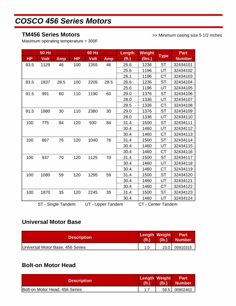
COSCO 456 Series Motors
TM456 Series Motors
Maximum operating temperature = 300F
50 Hz 60 Hz Length Weight Type
Part HP Volt Amp HP Volt Amp (ft.) (lbs.) Number
83.5 1129 46 100 1355 46 26.6 1236 ST 32434101
25.6 1196 UT 32434102
26.1 1196 CT 32434103
83.5 1837 28.5 100 2205 28.5 26.6 1236 ST 32434104
25.6 1196 UT 32434105
91.5 991 60 110 1190 60 29.0 1376 ST 32434106
28.0 1336 UT 32434107
28.5 1336 CT 32434108
91.5 1980 30 110 2380 30 29.0 1376 ST 32434109
28.0 1336 UT 32434110
100 775 84 120 930 84 31.4 1500 ST 32434111
30.4 1460 UT 32434112
30.4 1460 CT 32434113
100 867 76 120 1040 76 31.4 1500 ST 32434114
30.4 1460 UT 32434115
30.4 1460 CT 32434116
100 937 70 120 1125 70 31.4 1500 ST 32434117
30.4 1460 UT 32434118
30.4 1460 CT 32434119
100 1080 59 120 1295 59 31.4 1500 ST 32434120
30.4 1460 UT 32434121
30.4 1460 CT 32434122
100 1870 35 120 2245 35 31.4 1500 ST 32434123
30.4 1460 UT 32434124
ST - Single Tandem UT - Upper Tandem CT - Center Tandem
Universal Motor Base
Description Length
(ft.) Weight
(lb.) Part
Number
Universal Motor Base, 456 Series 1.0 23.0 00910315
Bolt-on Motor Head
Description Length
(ft.) Weight
(lb.) Part
Number
Bolt-on Motor Head, 456 Series 1.7 59.5 00902463
>> Minimum casing size 5 1/2 inches
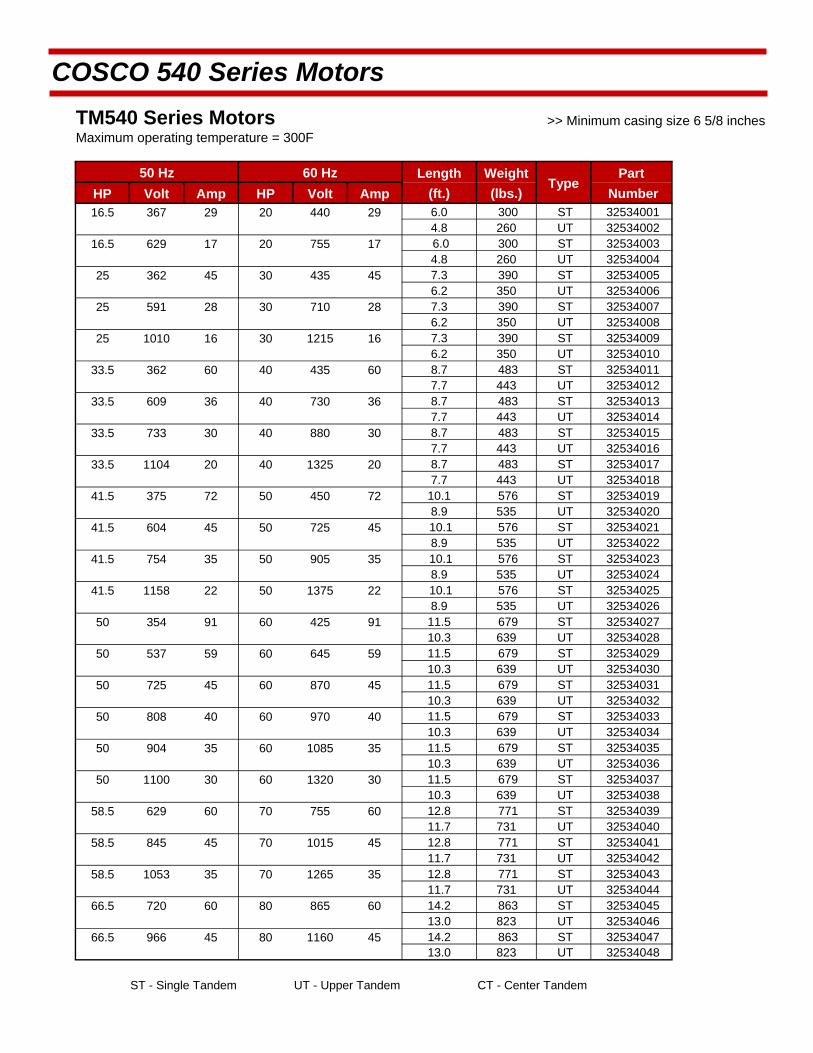
COSCO 540 Series Motors
TM540 Series Motors
Maximum operating temperature = 300F
50 Hz 60 Hz Length Weight Type
Part HP Volt Amp HP Volt Amp (ft.) (lbs.) Number 16.5 367 29 20 440 29 6.0 300 ST 32534001
4.8 260 UT 32534002 16.5 629 17 20 755 17 6.0 300 ST 32534003
4.8 260 UT 32534004 25 362 45 30 435 45 7.3 390 ST 32534005 6.2 350 UT 32534006
25 591 28 30 710 28 7.3 390 ST 32534007 6.2 350 UT 32534008
25 1010 16 30 1215 16 7.3 390 ST 32534009 6.2 350 UT 32534010
33.5 362 60 40 435 60 8.7 483 ST 32534011 7.7 443 UT 32534012
33.5 609 36 40 730 36 8.7 483 ST 32534013 7.7 443 UT 32534014
33.5 733 30 40 880 30 8.7 483 ST 32534015 7.7 443 UT 32534016
33.5 1104 20 40 1325 20 8.7 483 ST 32534017 7.7 443 UT 32534018
41.5 375 72 50 450 72 10.1 576 ST 32534019 8.9 535 UT 32534020
41.5 604 45 50 725 45 10.1 576 ST 32534021 8.9 535 UT 32534022
41.5 754 35 50 905 35 10.1 576 ST 32534023 8.9 535 UT 32534024
41.5 1158 22 50 1375 22 10.1 576 ST 32534025 8.9 535 UT 32534026
50 354 91 60 425 91 11.5 679 ST 32534027 10.3 639 UT 32534028
50 537 59 60 645 59 11.5 679 ST 32534029 10.3 639 UT 32534030
50 725 45 60 870 45 11.5 679 ST 32534031 10.3 639 UT 32534032
50 808 40 60 970 40 11.5 679 ST 32534033 10.3 639 UT 32534034
50 904 35 60 1085 35 11.5 679 ST 32534035 10.3 639 UT 32534036
50 1100 30 60 1320 30 11.5 679 ST 32534037 10.3 639 UT 32534038
58.5 629 60 70 755 60 12.8 771 ST 32534039 11.7 731 UT 32534040
58.5 845 45 70 1015 45 12.8 771 ST 32534041 11.7 731 UT 32534042
58.5 1053 35 70 1265 35 12.8 771 ST 32534043 11.7 731 UT 32534044
66.5 720 60 80 865 60 14.2 863 ST 32534045 13.0 823 UT 32534046
66.5 966 45 80 1160 45 14.2 863 ST 32534047 13.0 823 UT 32534048
ST - Single Tandem UT - Upper Tandem CT - Center Tandem
>> Minimum casing size 6 5/8 inches
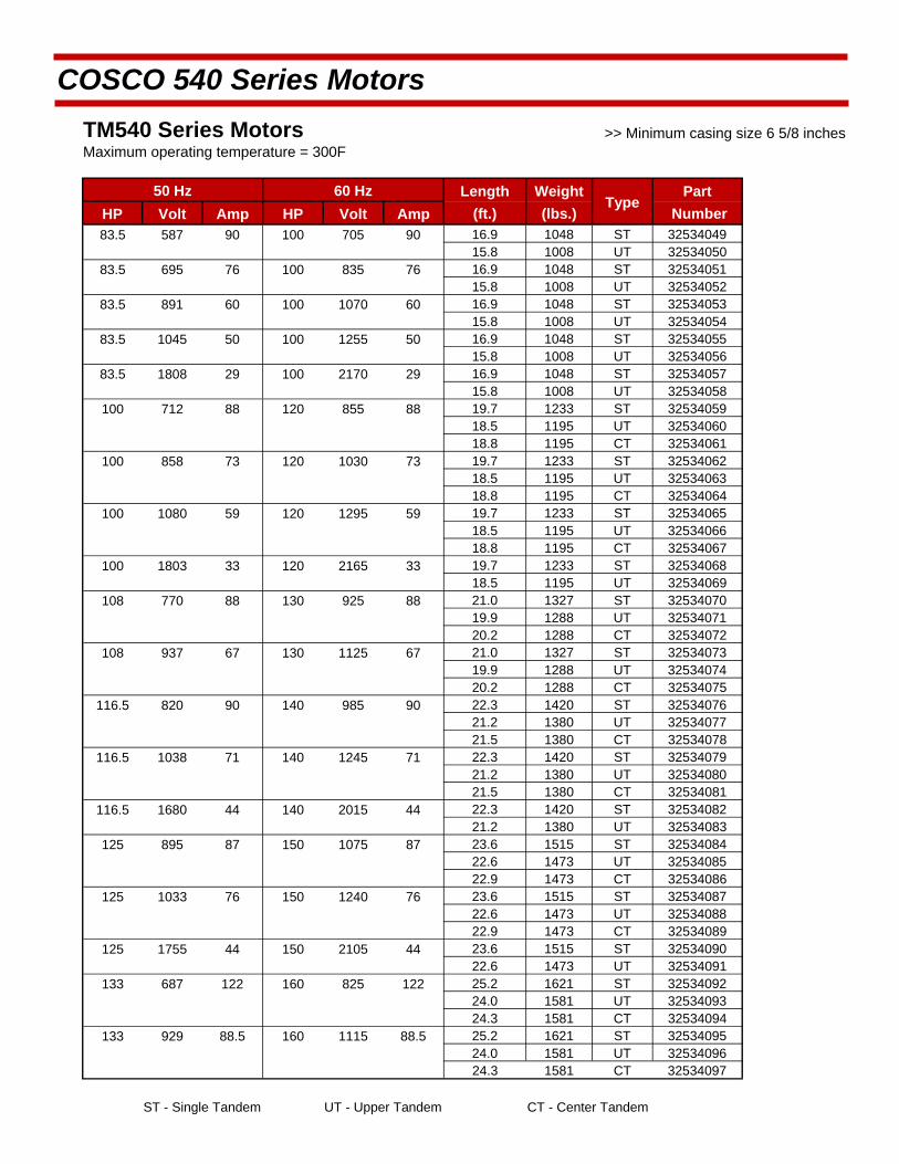
COSCO 540 Series Motors
TM540 Series Motors
Maximum operating temperature = 300F
50 Hz 60 Hz Length Weight Type
Part HP Volt Amp HP Volt Amp (ft.) (lbs.) Number 83.5 587 90 100 705 90 16.9 1048 ST 32534049
15.8 1008 UT 32534050 83.5 695 76 100 835 76 16.9 1048 ST 32534051
15.8 1008 UT 32534052 83.5 891 60 100 1070 60 16.9 1048 ST 32534053
15.8 1008 UT 32534054 83.5 1045 50 100 1255 50 16.9 1048 ST 32534055
15.8 1008 UT 32534056 83.5 1808 29 100 2170 29 16.9 1048 ST 32534057
15.8 1008 UT 32534058 100 712 88 120 855 88 19.7 1233 ST 32534059
18.5 1195 UT 32534060 18.8 1195 CT 32534061
100 858 73 120 1030 73 19.7 1233 ST 32534062 18.5 1195 UT 32534063 18.8 1195 CT 32534064
100 1080 59 120 1295 59 19.7 1233 ST 32534065 18.5 1195 UT 32534066 18.8 1195 CT 32534067
100 1803 33 120 2165 33 19.7 1233 ST 32534068 18.5 1195 UT 32534069
108 770 88 130 925 88 21.0 1327 ST 32534070 19.9 1288 UT 32534071 20.2 1288 CT 32534072
108 937 67 130 1125 67 21.0 1327 ST 32534073 19.9 1288 UT 32534074 20.2 1288 CT 32534075
116.5 820 90 140 985 90 22.3 1420 ST 32534076 21.2 1380 UT 32534077 21.5 1380 CT 32534078
116.5 1038 71 140 1245 71 22.3 1420 ST 32534079 21.2 1380 UT 32534080 21.5 1380 CT 32534081
116.5 1680 44 140 2015 44 22.3 1420 ST 32534082 21.2 1380 UT 32534083
125 895 87 150 1075 87 23.6 1515 ST 32534084 22.6 1473 UT 32534085 22.9 1473 CT 32534086
125 1033 76 150 1240 76 23.6 1515 ST 32534087 22.6 1473 UT 32534088 22.9 1473 CT 32534089
125 1755 44 150 2105 44 23.6 1515 ST 32534090 22.6 1473 UT 32534091
133 687 122 160 825 122 25.2 1621 ST 32534092 24.0 1581 UT 32534093 24.3 1581 CT 32534094
133 929 88.5 160 1115 88.5 25.2 1621 ST 32534095 24.0 1581 UT 32534096 24.3 1581 CT 32534097
ST - Single Tandem UT - Upper Tandem CT - Center Tandem
>> Minimum casing size 6 5/8 inches
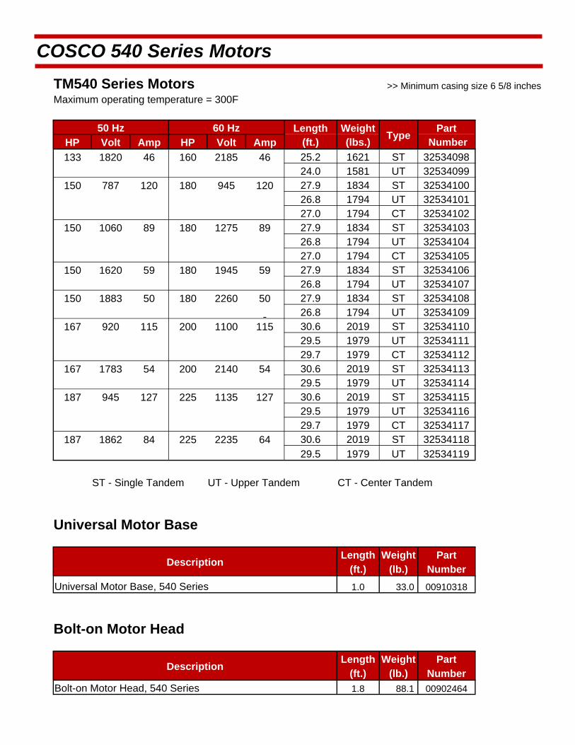
COSCO 540 Series Motors
TM540 Series Motors
Maximum operating temperature = 300F
50 Hz 60 Hz Length Weight Type
Part HP Volt Amp HP Volt Amp (ft.) (lbs.) Number 133 1820 46 160 2185 46 25.2 1621 ST 32534098
24.0 1581 UT 32534099 150 787 120 180 945 120 27.9 1834 ST 32534100
26.8 1794 UT 32534101 27.0 1794 CT 32534102
150 1060 89 180 1275 89 27.9 1834 ST 32534103 26.8 1794 UT 32534104
27.0 1794 CT 32534105 150 1620 59 180 1945 59 27.9 1834 ST 32534106
26.8 1794 UT 32534107 150 1883 50 180 2260 50 27.9 1834 ST 32534108
26.8 1794 UT 32534109 167 920 115 200 1100 115 30.6 2019 ST 32534110
29.5 1979 UT 32534111 29.7 1979 CT 32534112
167 1783 54 200 2140 54 30.6 2019 ST 32534113 29.5 1979 UT 32534114
187 945 127 225 1135 127 30.6 2019 ST 32534115 29.5 1979 UT 32534116 29.7 1979 CT 32534117
187 1862 84 225 2235 64 30.6 2019 ST 32534118
29.5 1979 UT 32534119
ST - Single Tandem UT - Upper Tandem CT - Center Tandem
Universal Motor Base
Description Length
(ft.) Weight
(lb.) Part
Number
Universal Motor Base, 540 Series 1.0 33.0 00910318
Bolt-on Motor Head
Description Length
(ft.) Weight
(lb.) Part
Number Bolt-on Motor Head, 540 Series 1.8 88.1 00902464
>> Minimum casing size 6 5/8 inches
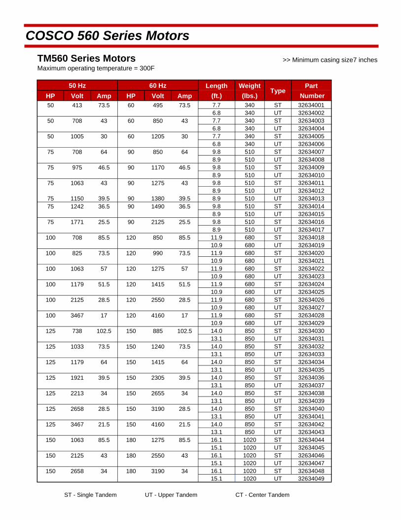
COSCO 560 Series Motors
TM560 Series Motors
Maximum operating temperature = 300F
50 Hz 60 Hz Length Weight Type
Part HP Volt Amp HP Volt Amp (ft.) (lbs.) Number 50 413 73.5 60 495 73.5 7.7 340 ST 32634001 6.8 340 UT 32634002
50 708 43 60 850 43 7.7 340 ST 32634003 6.8 340 UT 32634004
50 1005 30 60 1205 30 7.7 340 ST 32634005 6.8 340 UT 32634006
75 708 64 90 850 64 9.8 510 ST 32634007 8.9 510 UT 32634008
75 975 46.5 90 1170 46.5 9.8 510 ST 32634009 8.9 510 UT 32634010
75 1063 43 90 1275 43 9.8 510 ST 32634011 8.9 510 UT 32634012
75 1150 39.5 90 1380 39.5 8.9 510 UT 32634013 75 1242 36.5 90 1490 36.5 9.8 510 ST 32634014 8.9 510 UT 32634015
75 1771 25.5 90 2125 25.5 9.8 510 ST 32634016 8.9 510 UT 32634017
100 708 85.5 120 850 85.5 11.9 680 ST 32634018 10.9 680 UT 32634019
100 825 73.5 120 990 73.5 11.9 680 ST 32634020 10.9 680 UT 32634021
100 1063 57 120 1275 57 11.9 680 ST 32634022 10.9 680 UT 32634023
100 1179 51.5 120 1415 51.5 11.9 680 ST 32634024 10.9 680 UT 32634025
100 2125 28.5 120 2550 28.5 11.9 680 ST 32634026 10.9 680 UT 32634027
100 3467 17 120 4160 17 11.9 680 ST 32634028 10.9 680 UT 32634029
125 738 102.5 150 885 102.5 14.0 850 ST 32634030 13.1 850 UT 32634031
125 1033 73.5 150 1240 73.5 14.0 850 ST 32634032 13.1 850 UT 32634033
125 1179 64 150 1415 64 14.0 850 ST 32634034 13.1 850 UT 32634035
125 1921 39.5 150 2305 39.5 14.0 850 ST 32634036 13.1 850 UT 32634037
125 2213 34 150 2655 34 14.0 850 ST 32634038 13.1 850 UT 32634039
125 2658 28.5 150 3190 28.5 14.0 850 ST 32634040 13.1 850 UT 32634041
125 3467 21.5 150 4160 21.5 14.0 850 ST 32634042 13.1 850 UT 32634043
150 1063 85.5 180 1275 85.5 16.1 1020 ST 32634044 15.1 1020 UT 32634045
150 2125 43 180 2550 43 16.1 1020 ST 32634046 15.1 1020 UT 32634047
150 2658 34 180 3190 34 16.1 1020 ST 32634048 15.1 1020 UT 32634049
ST - Single Tandem UT - Upper Tandem CT - Center Tandem
>> Minimum casing size7 inches

COSCO 560 Series Motors
TM560 Series Motors
Maximum operating temperature = 300F
50 Hz 60 Hz Length Weight Type
Part HP Volt Amp HP Volt Amp (ft.) (lbs.) Number 175 1033 102.5 210 1240 102.5 17.2 1190 UT 32634050 175 2075 51.5 210 2490 51.5 18.2 1190 ST 32634051
17.2 1190 UT 32634052 175 3100 34 210 3720 34 18.2 1190 ST 32634053
17.2 1190 UT 32634054 200 1179 102.5 240 1415 102.5 20.3 1395 ST 32634055
19.3 1395 UT 32634056 19.5 1395 CT 32634057
200 2129 57 240 2550 57 20.3 1395 ST 32634058 19.3 1395 UT 32634059
200 3542 34 240 4250 34 20.3 1395 ST 32634060 19.3 1395 UT 32634061
225 1063 128.5 270 1275 128.5 22.4 1570 ST 32634062 21.4 1570 UT 32634063 21.5 1570 CT 32634064
225 1329 102.5 270 1595 102.5 22.4 1570 ST 32634065 21.4 1570 UT 32634066 21.5 1570 CT 32634067
225 2125 64 270 2550 64 22.4 1570 ST 32634068 21.4 1570 UT 32634069
250 1029 147.5 300 1235 147.5 23.5 1600 UT 32634070 23.6 1600 CT 32634071
250 1179 128.5 300 1415 128.5 24.5 1600 ST 32634072 23.5 1600 UT 32634073 23.6 1600 CT 32634074
250 1743 86.5 300 2091 86.5 23.5 1600 UT 32634075 23.6 1600 CT 32634076
250 2067 73.5 300 2480 73.5 24.5 1600 ST 32634077 23.5 1600 UT 32634078
250 3542 43 300 4250 43 24.5 1600 ST 32634079 23.5 1600 UT 32634080
275 1300 128.5 330 1560 128.5 26.5 1840 ST 32634081 25.6 1840 UT 32634082 25.7 1840 CT 32634083
275 1625 102.5 330 1950 102.5 26.5 1840 ST 32634084 25.6 1840 UT 32634085 25.7 1840 CT 32634086
275 2271 73.5 330 2725 73.5 26.5 1840 ST 32634087 25.6 1840 UT 32634088
275 2921 57 330 3505 57 26.5 1840 ST 32634089 25.6 1840 UT 32634090
275 3246 51.5 330 3895 51.5 26.5 1840 ST 32634091 25.6 1840 UT 32634092
275 1133 147.5 330 1360 147.5 25.7 1840 CT 32634093 300 1417 128.5 360 1700 128.5 28.6 2005 ST 32634094
27.7 2005 UT 32634095 27.8 2005 CT 32634096
300 1771 102.5 360 2125 102.5 27.7 2005 UT 32634097 27.8 2005 CT 32634098
ST - Single Tandem UT - Upper Tandem CT - Center Tandem
>> Minimum casing size7 inches
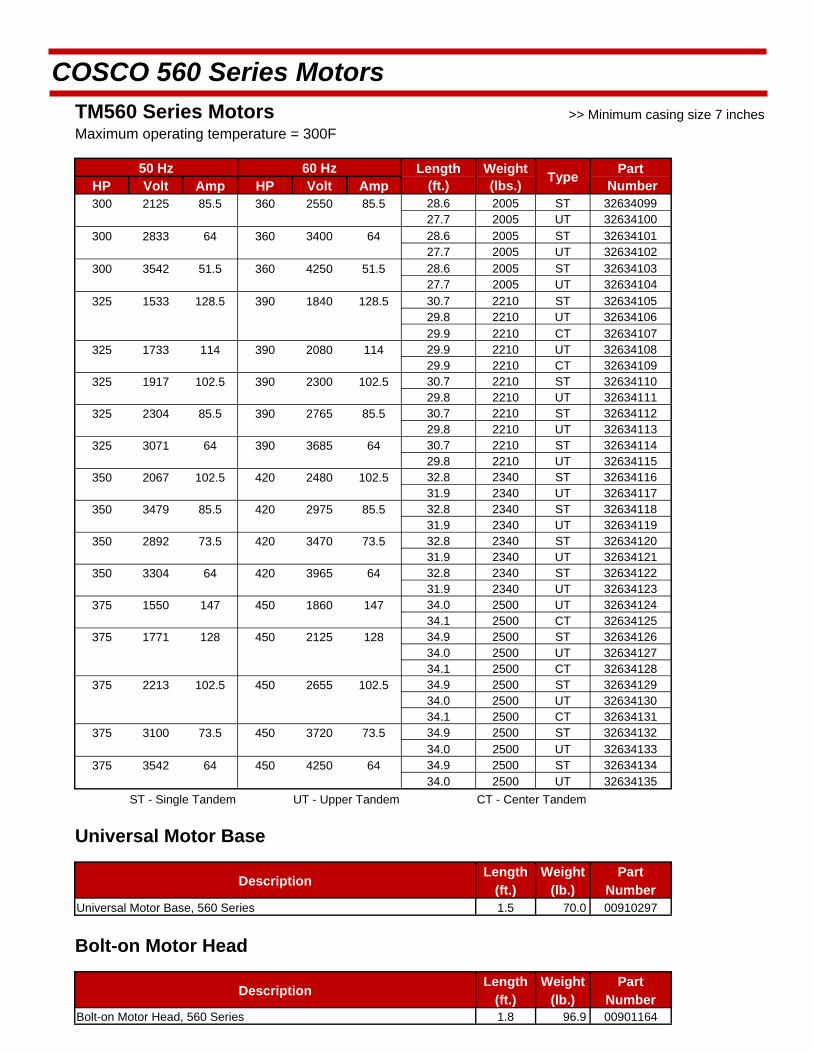
COSCO 560 Series Motors
TM560 Series Motors
Maximum operating temperature = 300F
50 Hz 60 Hz Length Weight Type
Part HP Volt Amp HP Volt Amp (ft.) (lbs.) Number 300 2125 85.5 360 2550 85.5 28.6 2005 ST 32634099
27.7 2005 UT 32634100 300 2833 64 360 3400 64 28.6 2005 ST 32634101
27.7 2005 UT 32634102 300 3542 51.5 360 4250 51.5 28.6 2005 ST 32634103
27.7 2005 UT 32634104 325 1533 128.5 390 1840 128.5 30.7 2210 ST 32634105
29.8 2210 UT 32634106 29.9 2210 CT 32634107
325 1733 114 390 2080 114 29.9 2210 UT 32634108 29.9 2210 CT 32634109
325 1917 102.5 390 2300 102.5 30.7 2210 ST 32634110 29.8 2210 UT 32634111
325 2304 85.5 390 2765 85.5 30.7 2210 ST 32634112 29.8 2210 UT 32634113
325 3071 64 390 3685 64 30.7 2210 ST 32634114 29.8 2210 UT 32634115
350 2067 102.5 420 2480 102.5 32.8 2340 ST 32634116 31.9 2340 UT 32634117
350 3479 85.5 420 2975 85.5 32.8 2340 ST 32634118 31.9 2340 UT 32634119
350 2892 73.5 420 3470 73.5 32.8 2340 ST 32634120 31.9 2340 UT 32634121
350 3304 64 420 3965 64 32.8 2340 ST 32634122 31.9 2340 UT 32634123
375 1550 147 450 1860 147 34.0 2500 UT 32634124 34.1 2500 CT 32634125
375 1771 128 450 2125 128 34.9 2500 ST 32634126 34.0 2500 UT 32634127 34.1 2500 CT 32634128
375 2213 102.5 450 2655 102.5 34.9 2500 ST 32634129 34.0 2500 UT 32634130 34.1 2500 CT 32634131
375 3100 73.5 450 3720 73.5 34.9 2500 ST 32634132 34.0 2500 UT 32634133
375 3542 64 450 4250 64 34.9 2500 ST 32634134 34.0 2500 UT 32634135 ST - Single Tandem UT - Upper Tandem CT - Center Tandem
Universal Motor Base
Description Length
(ft.) Weight
(lb.) Part
Number Universal Motor Base, 560 Series 1.5 70.0 00910297
Bolt-on Motor Head
Description Length
(ft.) Weight
(lb.) Part
Number Bolt-on Motor Head, 560 Series 1.8 96.9 00901164
>> Minimum casing size 7 inches
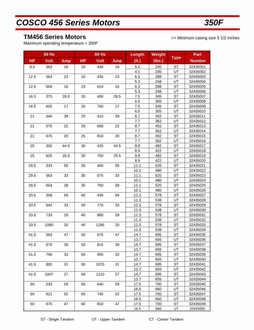
COSCO 456 Series Motors 350F
TM456 Series Motors
Maximum operating temperature = 350F
50 Hz 60 Hz Length Weight Type
Part HP Volt Amp HP Volt Amp (ft.) (lbs.) Number 8.5 363 16 10 435 16 5.1 240 ST 32435001 4.1 200 UT 32435002
12.5 363 23 15 435 23 6.3 288 ST 32435003 5.3 248 UT 32435004
12.5 509 16 15 610 16 6.3 288 ST 32435005 5.3 248 UT 32435006
16.5 375 28.5 20 450 28.5 7.5 345 ST 32435007 6.5 305 UT 32435008
16.5 625 17 20 750 17 7.5 345 ST 32435009 6.5 305 UT 32435010
21 340 39 25 410 39 8.7 402 ST 32435011 7.7 362 UT 32435012
21 575 22 25 690 22 8.7 402 ST 32435013 7.7 362 UT 32435014
21 675 20 25 810 20 8.7 402 ST 32435015 7.7 362 UT 32435016
25 355 44.5 30 425 44.5 9.9 482 ST 32435017 8.9 422 UT 32435018
25 625 25.5 30 750 25.5 9.9 482 ST 32435019 8.9 422 UT 32435020
29.5 333 55 35 400 55 11.1 520 ST 32435021 10.1 480 UT 32435022
29.5 563 33 35 675 33 11.1 520 ST 32435023 10.1 480 UT 32435024
29.5 654 28 35 750 28 11.1 520 ST 32435025 10.1 480 UT 32435026
33.5 358 59 40 430 59 12.3 578 ST 32435027 11.3 538 UT 32435028
33.5 642 33 40 770 33 12.3 578 ST 32435029 11.3 538 UT 32435030
33.5 733 29 40 880 29 12.3 578 ST 32435031 11.3 538 UT 32435032
33.5 1080 20 40 1295 20 12.3 578 ST 32435033 11.3 538 UT 32435034
41.5 563 47 50 675 47 14.7 695 ST 32435035 13.7 655 UT 32435036
41.5 679 39 50 815 39 14.7 695 ST 32435037 13.7 655 UT 32435038
41.5 796 33 50 955 33 14.7 695 ST 32435039 13.7 655 UT 32435040
41.5 892 31 50 1070 31 14.7 695 ST 32435041 13.7 655 UT 32435042
41.5 1007 27 50 1210 27 14.7 695 ST 32435043 13.7 655 UT 32435044
50 533 59 60 640 59 17.5 700 ST 32435045 16.5 660 UT 32435046
50 621 52 60 745 52 17.5 700 ST 32435047 16.5 660 UT 32435048
50 675 47 60 810 47 17.5 700 ST 32435049 16.5 660 UT 32435050
ST - Single Tandem UT - Upper Tandem CT - Center Tandem
>> Minimum casing size 5 1/2 inches
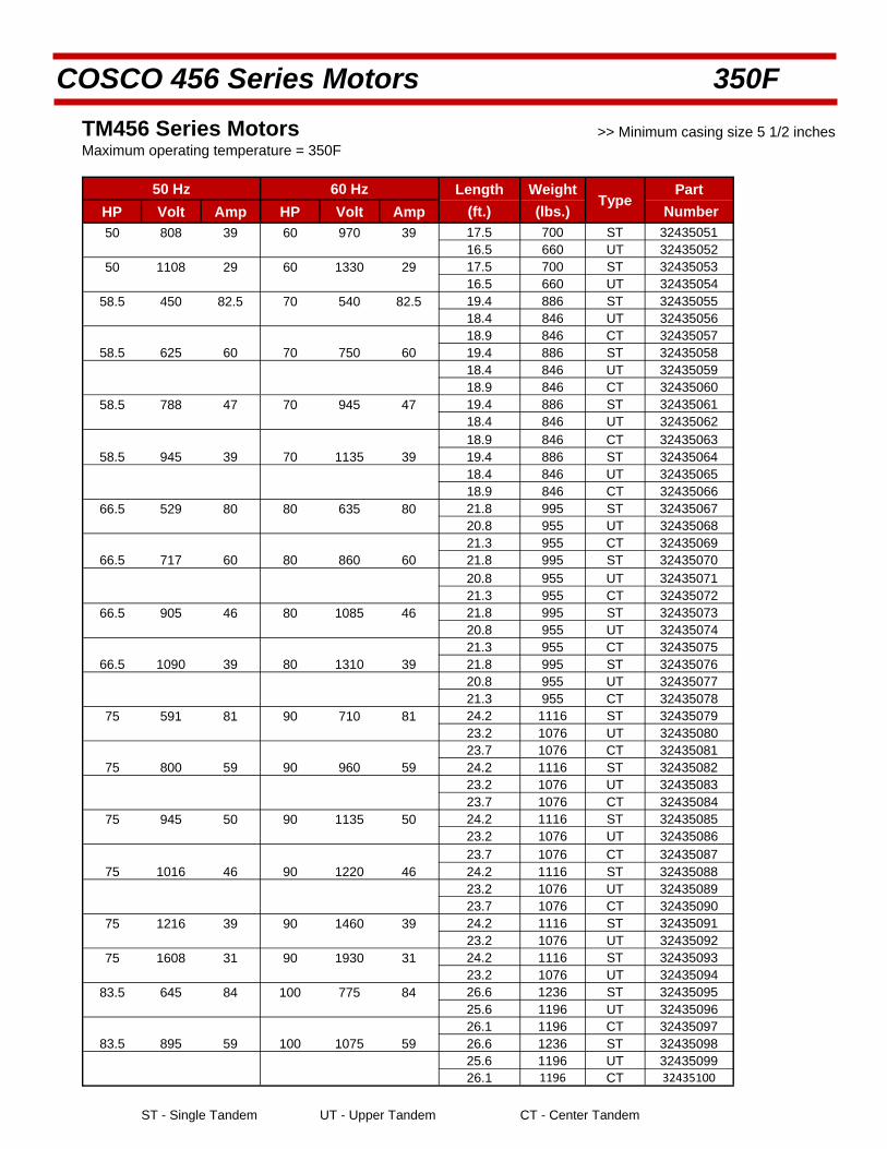
COSCO 456 Series Motors 350F
TM456 Series Motors
Maximum operating temperature = 350F
50 Hz 60 Hz Length Weight Type
Part HP Volt Amp HP Volt Amp (ft.) (lbs.) Number 50 808 39 60 970 39 17.5 700 ST 32435051 16.5 660 UT 32435052
50 1108 29 60 1330 29 17.5 700 ST 32435053 16.5 660 UT 32435054
58.5 450 82.5 70 540 82.5 19.4 886 ST 32435055 18.4 846 UT 32435056 18.9 846 CT 32435057
58.5 625 60 70 750 60 19.4 886 ST 32435058 18.4 846 UT 32435059 18.9 846 CT 32435060
58.5 788 47 70 945 47 19.4 886 ST 32435061 18.4 846 UT 32435062
18.9 846 CT 32435063 58.5 945 39 70 1135 39 19.4 886 ST 32435064
18.4 846 UT 32435065 18.9 846 CT 32435066
66.5 529 80 80 635 80 21.8 995 ST 32435067 20.8 955 UT 32435068 21.3 955 CT 32435069
66.5 717 60 80 860 60 21.8 995 ST 32435070
20.8 955 UT 32435071 21.3 955 CT 32435072
66.5 905 46 80 1085 46 21.8 995 ST 32435073 20.8 955 UT 32435074 21.3 955 CT 32435075
66.5 1090 39 80 1310 39 21.8 995 ST 32435076 20.8 955 UT 32435077 21.3 955 CT 32435078
75 591 81 90 710 81 24.2 1116 ST 32435079 23.2 1076 UT 32435080 23.7 1076 CT 32435081
75 800 59 90 960 59 24.2 1116 ST 32435082 23.2 1076 UT 32435083 23.7 1076 CT 32435084
75 945 50 90 1135 50 24.2 1116 ST 32435085 23.2 1076 UT 32435086 23.7 1076 CT 32435087
75 1016 46 90 1220 46 24.2 1116 ST 32435088 23.2 1076 UT 32435089 23.7 1076 CT 32435090
75 1216 39 90 1460 39 24.2 1116 ST 32435091 23.2 1076 UT 32435092
75 1608 31 90 1930 31 24.2 1116 ST 32435093 23.2 1076 UT 32435094
83.5 645 84 100 775 84 26.6 1236 ST 32435095 25.6 1196 UT 32435096 26.1 1196 CT 32435097
83.5 895 59 100 1075 59 26.6 1236 ST 32435098 25.6 1196 UT 32435099 26.1 1196 CT 32435100
ST - Single Tandem UT - Upper Tandem CT - Center Tandem
>> Minimum casing size 5 1/2 inches
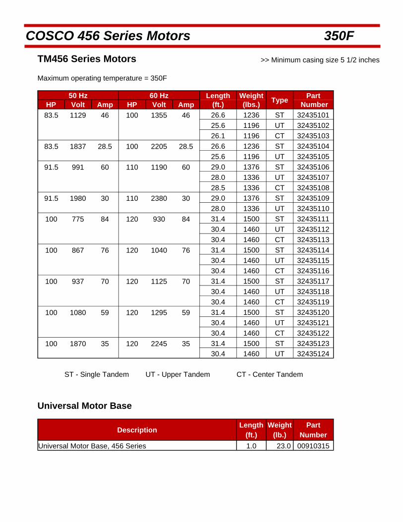
COSCO 456 Series Motors 350F
TM456 Series Motors
Maximum operating temperature = 350F
50 Hz 60 Hz Length Weight Type
Part HP Volt Amp HP Volt Amp (ft.) (lbs.) Number
83.5 1129 46 100 1355 46 26.6 1236 ST 32435101
25.6 1196 UT 32435102
26.1 1196 CT 32435103
83.5 1837 28.5 100 2205 28.5 26.6 1236 ST 32435104
25.6 1196 UT 32435105
91.5 991 60 110 1190 60 29.0 1376 ST 32435106
28.0 1336 UT 32435107
28.5 1336 CT 32435108
91.5 1980 30 110 2380 30 29.0 1376 ST 32435109
28.0 1336 UT 32435110
100 775 84 120 930 84 31.4 1500 ST 32435111
30.4 1460 UT 32435112
30.4 1460 CT 32435113
100 867 76 120 1040 76 31.4 1500 ST 32435114
30.4 1460 UT 32435115
30.4 1460 CT 32435116
100 937 70 120 1125 70 31.4 1500 ST 32435117
30.4 1460 UT 32435118
30.4 1460 CT 32435119
100 1080 59 120 1295 59 31.4 1500 ST 32435120
30.4 1460 UT 32435121
30.4 1460 CT 32435122
100 1870 35 120 2245 35 31.4 1500 ST 32435123 30.4 1460 UT 32435124
ST - Single Tandem UT - Upper Tandem CT - Center Tandem
Universal Motor Base
Description Length
(ft.) Weight
(lb.) Part
Number Universal Motor Base, 456 Series 1.0 23.0 00910315
>> Minimum casing size 5 1/2 inches

COSCO 540 Series Motors 350F
TM540 Series Motors
Maximum operating temperature = 350F
50 Hz 60 Hz Length Weight Type
Part HP Volt Amp HP Volt Amp (ft.) (lbs.) Number 16.5 367 29 20 440 29 6.0 300 ST 32535001
4.8 260 UT 32535002 16.5 629 17 20 755 17 6.0 300 ST 32535003
4.8 260 UT 32535004 25 362 45 30 435 45 7.3 390 ST 32535005 6.2 350 UT 32535006
25 591 28 30 710 28 7.3 390 ST 32535007 6.2 350 UT 32535008
25 1010 16 30 1215 16 7.3 390 ST 32535009 6.2 350 UT 32535010
33.5 362 60 40 435 60 8.7 483 ST 32535011 7.7 443 UT 32535012
33.5 609 36 40 730 36 8.7 483 ST 32535013 7.7 443 UT 32535014
33.5 733 30 40 880 30 8.7 483 ST 32535015 7.7 443 UT 32535016
33.5 1104 20 40 1325 20 8.7 483 ST 32535017 7.7 443 UT 32535018
41.5 375 72 50 450 72 10.1 576 ST 32535019 8.9 535 UT 32535020
41.5 604 45 50 725 45 10.1 576 ST 32535021 8.9 535 UT 32535022
41.5 754 35 50 905 35 10.1 576 ST 32535023 8.9 535 UT 32535024
41.5 1158 22 50 1375 22 10.1 576 ST 32535025 8.9 535 UT 32535026
50 354 91 60 425 91 11.5 679 ST 32535027 10.3 639 UT 32535028
50 537 59 60 645 59 11.5 679 ST 32535029 10.3 639 UT 32535030
50 725 45 60 870 45 11.5 679 ST 32535031 10.3 639 UT 32535032
50 808 40 60 970 40 11.5 679 ST 32535033 10.3 639 UT 32535034
50 904 35 60 1085 35 11.5 679 ST 32535035 10.3 639 UT 32535036
50 1100 30 60 1320 30 11.5 679 ST 32535037 10.3 639 UT 32535038
58.5 629 60 70 755 60 12.8 771 ST 32535039 11.7 731 UT 32535040
58.5 845 45 70 1015 45 12.8 771 ST 32535041 11.7 731 UT 32535042
58.5 1053 35 70 1265 35 12.8 771 ST 32535043 11.7 731 UT 32535044
66.5 720 60 80 865 60 14.2 863 ST 32535045 13.0 823 UT 32535046
66.5 966 45 80 1160 45 14.2 863 ST 32535047 13.0 823 UT 32535048 ST - Single Tandem UT - Upper Tandem CT - Center Tandem
>> Minimum casing size 6 5/8 inches

COSCO 540 Series Motors 350F
TM540 Series Motors
Maximum operating temperature = 350F
50 Hz 60 Hz Length Weight Type
Part HP Volt Amp HP Volt Amp (ft.) (lbs.) Number 83.5 587 90 100 705 90 16.9 1048 ST 32535049
15.8 1008 UT 32535050 83.5 695 76 100 835 76 16.9 1048 ST 32535051
15.8 1008 UT 32535052 83.5 891 60 100 1070 60 16.9 1048 ST 32535053
15.8 1008 UT 32535054 83.5 1045 50 100 1255 50 16.9 1048 ST 32535055
15.8 1008 UT 32535056 83.5 1808 29 100 2170 29 16.9 1048 ST 32535057
15.8 1008 UT 32535058 100 712 88 120 855 88 19.7 1233 ST 32535059
18.5 1195 UT 32535060 18.8 1195 CT 32535061
100 858 73 120 1030 73 19.7 1233 ST 32535062 18.5 1195 UT 32535063 18.8 1195 CT 32535064
100 1080 59 120 1295 59 19.7 1233 ST 32535065 18.5 1195 UT 32535066 18.8 1195 CT 32535067
100 1803 33 120 2165 33 19.7 1233 ST 32535068 18.5 1195 UT 32535069
108 770 88 130 925 88 21.0 1327 ST 32535070 19.9 1288 UT 32535071 20.2 1288 CT 32535072
108 937 67 130 1125 67 21.0 1327 ST 32535073 19.9 1288 UT 32535074 20.2 1288 CT 32535075
116.5 820 90 140 985 90 22.3 1420 ST 32535076 21.2 1380 UT 32535077 21.5 1380 CT 32535078
116.5 1038 71 140 1245 71 22.3 1420 ST 32535079 21.2 1380 UT 32535080 21.5 1380 CT 32535081
116.5 1680 44 140 2015 44 22.3 1420 ST 32535082 21.2 1380 UT 32535083
125 895 87 150 1075 87 23.6 1515 ST 32535084 22.6 1473 UT 32535085 22.9 1473 CT 32535086
125 1033 76 150 1240 76 23.6 1515 ST 32535087 22.6 1473 UT 32535088 22.9 1473 CT 32535089
125 1755 44 150 2105 44 23.6 1515 ST 32535090 22.6 1473 UT 32535091
133 687 122 160 825 122 25.2 1621 ST 32535092 24.0 1581 UT 32535093 24.3 1581 CT 32535094
133 929 88.5 160 1115 88.5 25.2 1621 ST 32535095 24.0 1581 UT 32535096 24.3 1581 CT 32535097 ST - Single Tandem UT - Upper Tandem CT - Center Tandem
>> Minimum casing size 6 5/8 inches
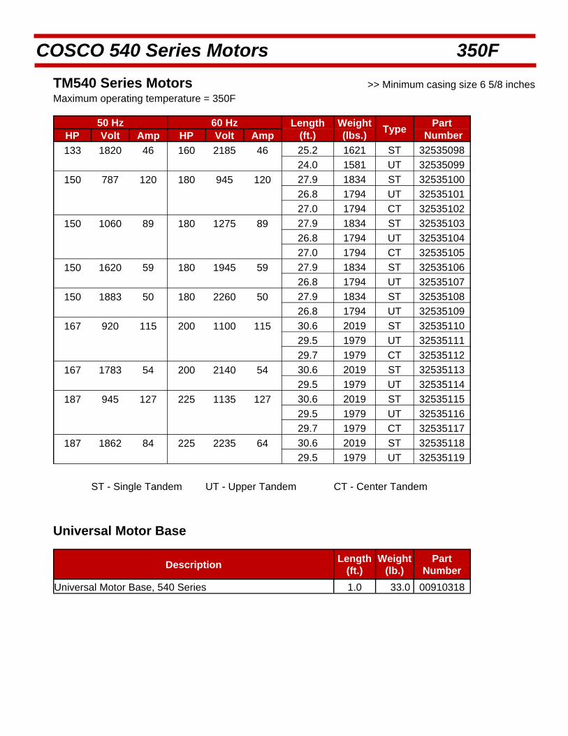
COSCO 540 Series Motors 350F
TM540 Series Motors >> Minimum casing size 6 5/8 inches Maximum operating temperature = 350F
50 Hz 60 Hz Length Weight Type
Part HP Volt Amp HP Volt Amp (ft.) (lbs.) Number
133 1820 46 160 2185 46 25.2 1621 ST 32535098
24.0 1581 UT 32535099
150 787 120 180 945 120 27.9 1834 ST 32535100
26.8 1794 UT 32535101
27.0 1794 CT 32535102
150 1060 89 180 1275 89 27.9 1834 ST 32535103
26.8 1794 UT 32535104
27.0 1794 CT 32535105
150 1620 59 180 1945 59 27.9 1834 ST 32535106
26.8 1794 UT 32535107
150 1883 50 180 2260 50 27.9 1834 ST 32535108
26.8 1794 UT 32535109
167 920 115 200 1100 115 30.6 2019 ST 32535110
29.5 1979 UT 32535111
29.7 1979 CT 32535112
167 1783 54 200 2140 54 30.6 2019 ST 32535113
29.5 1979 UT 32535114
187 945 127 225 1135 127 30.6 2019 ST 32535115
29.5 1979 UT 32535116
29.7 1979 CT 32535117
187 1862 84 225 2235 64 30.6 2019 ST 32535118
29.5 1979 UT 32535119
ST - Single Tandem UT - Upper Tandem CT - Center Tandem
Universal Motor Base
Description Length
(ft.) Weight
(lb.) Part
Number Universal Motor Base, 540 Series 1.0 33.0 00910318

COSCO 560 Series Motors 350F
TM560 Series Motors
Maximum operating temperature = 350F
50 Hz 60 Hz Length Weight Type
Part HP Volt Amp HP Volt Amp (ft.) (lbs.) Number 50 413 73.5 60 495 73.5 7.7 340 ST 32635001 6.8 340 UT 32635002
50 708 43 60 850 43 7.7 340 ST 32635003 6.8 340 UT 32635004
50 1005 30 60 1205 30 7.7 340 ST 32635005 6.8 340 UT 32635006
75 708 64 90 850 64 9.8 510 ST 32635007 8.9 510 UT 32635008
75 975 46.5 90 1170 46.5 9.8 510 ST 32635009 8.9 510 UT 32635010
75 1063 43 90 1275 43 9.8 510 ST 32635011 8.9 510 UT 32635012
75 1150 39.5 90 1380 39.5 8.9 510 UT 32635013 75 1242 36.5 90 1490 36.5 9.8 510 ST 32635014 8.9 510 UT 32635015
75 1771 25.5 90 2125 25.5 9.8 510 ST 32635016 8.9 510 UT 32635017
100 708 85.5 120 850 85.5 11.9 680 ST 32635018 10.9 680 UT 32635019
100 825 73.5 120 990 73.5 11.9 680 ST 32635020 10.9 680 UT 32635021
100 1063 57 120 1275 57 11.9 680 ST 32635022 10.9 680 UT 32635023
100 1179 51.5 120 1415 51.5 11.9 680 ST 32635024 10.9 680 UT 32635025
100 2125 28.5 120 2550 28.5 11.9 680 ST 32635026 10.9 680 UT 32635027
100 3467 17 120 4160 17 11.9 680 ST 32635028 10.9 680 UT 32635029
125 738 102.5 150 885 102.5 14.0 850 ST 32635030 13.1 850 UT 32635031
125 1033 73.5 150 1240 73.5 14.0 850 ST 32635032 13.1 850 UT 32635033
125 1179 64 150 1415 64 14.0 850 ST 32635034 13.1 850 UT 32635035
125 1921 39.5 150 2305 39.5 14.0 850 ST 32635036 13.1 850 UT 32635037
125 2213 34 150 2655 34 14.0 850 ST 32635038 13.1 850 UT 32635039
125 2658 28.5 150 3190 28.5 14.0 850 ST 32635040 13.1 850 UT 32635041
125 3467 21.5 150 4160 21.5 14.0 850 ST 32635042 13.1 850 UT 32635043
150 1063 85.5 180 1275 85.5 16.1 1020 ST 32635044 15.1 1020 UT 32635045
150 2125 43 180 2550 43 16.1 1020 ST 32635046 15.1 1020 UT 32635047
150 2658 34 180 3190 34 16.1 1020 ST 32635048 15.1 1020 UT 32635049 ST - Single Tandem UT - Upper Tandem CT - Center Tandem
>> Minimum casing size 7 inches

COSCO 560 Series Motors 350F
TM560 Series Motors
Maximum operating temperature = 350F
50 Hz 60 Hz Length Weight Type
Part HP Volt Amp HP Volt Amp (ft.) (lbs.) Number 175 1033 102.5 210 1240 102.5 17.2 1190 UT 32635050 175 2075 51.5 210 2490 51.5 18.2 1190 ST 32635051
17.2 1190 UT 32635052 175 3100 34 210 3720 34 18.2 1190 ST 32635053
17.2 1190 UT 32635054 200 1179 102.5 240 1415 102.5 20.3 1395 ST 32635055
19.3 1395 UT 32635056 19.5 1395 CT 32635057
200 2129 57 240 2550 57 20.3 1395 ST 32635058 19.3 1395 UT 32635059
200 3542 34 240 4250 34 20.3 1395 ST 32635060 19.3 1395 UT 32635061
225 1063 128.5 270 1275 128.5 22.4 1570 ST 32635062 21.4 1570 UT 32635063 21.5 1570 CT 32635064
225 1329 102.5 270 1595 102.5 22.4 1570 ST 32635065 21.4 1570 UT 32635066 21.5 1570 CT 32635067
225 2125 64 270 2550 64 22.4 1570 ST 32635068 21.4 1570 UT 32635069
250 1029 147.5 300 1235 147.5 23.5 1600 UT 32635070 23.6 1600 CT 32635071
250 1179 128.5 300 1415 128.5 24.5 1600 ST 32635072 23.5 1600 UT 32635073 23.6 1600 CT 32635074
250 1743 86.5 300 2091 86.5 23.5 1600 UT 32635075 23.6 1600 CT 32635076
250 2067 73.5 300 2480 73.5 24.5 1600 ST 32635077 23.5 1600 UT 32635078
250 3542 43 300 4250 43 24.5 1600 ST 32635079 23.5 1600 UT 32635080
275 1300 128.5 330 1560 128.5 26.5 1840 ST 32635081 25.6 1840 UT 32635082 25.7 1840 CT 32635083
275 1625 102.5 330 1950 102.5 26.5 1840 ST 32635084 25.6 1840 UT 32635085 25.7 1840 CT 32635086
275 2271 73.5 330 2725 73.5 26.5 1840 ST 32635087 25.6 1840 UT 32635088
275 2921 57 330 3505 57 26.5 1840 ST 32635089 25.6 1840 UT 32635090
275 3246 51.5 330 3895 51.5 26.5 1840 ST 32635091 25.6 1840 UT 32635092
275 1133 147.5 330 1360 147.5 25.7 1840 CT 32635093 300 1417 128.5 360 1700 128.5 28.6 2005 ST 32635094
27.7 2005 UT 32635095 27.8 2005 CT 32635096
300 1771 102.5 360 2125 102.5 27.7 2005 UT 32635097 27.8 2005 CT 32635098 ST - Single Tandem UT - Upper Tandem CT - Center Tandem
>> Minimum casing size 7 inches
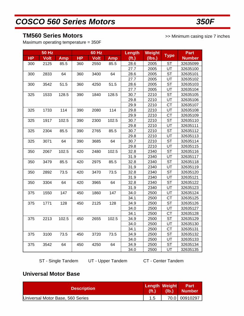
COSCO 560 Series Motors 350F
TM560 Series Motors >> Minimum casing size 7 inches Maximum operating temperature = 350F
50 Hz 60 Hz Length Weight Type
Part HP Volt Amp HP Volt Amp (ft.) (lbs.) Number 300 2125 85.5 360 2550 85.5 28.6 2005 ST 32635099
27.7 2005 UT 32635100 300 2833 64 360 3400 64 28.6 2005 ST 32635101
27.7 2005 UT 32635102 300 3542 51.5 360 4250 51.5 28.6 2005 ST 32635103
27.7 2005 UT 32635104 325 1533 128.5 390 1840 128.5 30.7 2210 ST 32635105
29.8 2210 UT 32635106 29.9 2210 CT 32635107
325 1733 114 390 2080 114 29.8 2210 UT 32635108 29.9 2210 CT 32635109
325 1917 102.5 390 2300 102.5 30.7 2210 ST 32635110 29.8 2210 UT 32635111
325 2304 85.5 390 2765 85.5 30.7 2210 ST 32635112 29.8 2210 UT 32635113
325 3071 64 390 3685 64 30.7 2210 ST 32635114 29.8 2210 UT 32635115
350 2067 102.5 420 2480 102.5 32.8 2340 ST 32635116 31.9 2340 UT 32635117
350 3479 85.5 420 2975 85.5 32.8 2340 ST 32635118 31.9 2340 UT 32635119
350 2892 73.5 420 3470 73.5 32.8 2340 ST 32635120 31.9 2340 UT 32635121
350 3304 64 420 3965 64 32.8 2340 ST 32635122 31.9 2340 UT 32635123
375 1550 147 450 1860 147 34.0 2500 UT 32635124 34.1 2500 CT 32635125
375 1771 128 450 2125 128 34.9 2500 ST 32635126 34.0 2500 UT 32635127 34.1 2500 CT 32635128
375 2213 102.5 450 2655 102.5 34.9 2500 ST 32635129 34.0 2500 UT 32635130 34.1 2500 CT 32635131
375 3100 73.5 450 3720 73.5 34.9 2500 ST 32635132 34.0 2500 UT 32635133
375 3542 64 450 4250 64 34.9 2500 ST 32635134 34.0 2500 UT 32635135
ST - Single Tandem UT - Upper Tandem CT - Center Tandem
Universal Motor Base
Description Length
(ft.) Weight
(lb.) Part
Number Universal Motor Base, 560 Series 1.5 70.0 00910297
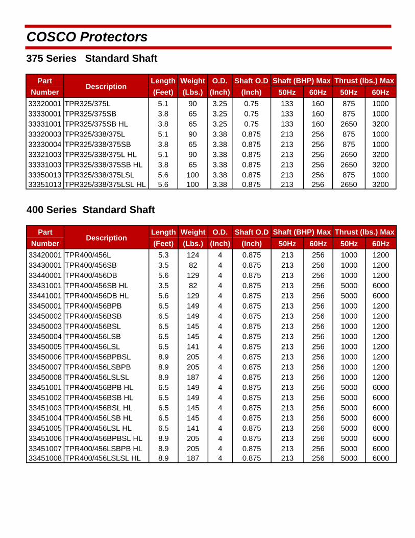
COSCO Protectors
Part Description
Length Weight O.D. Shaft O.D Shaft (BHP) Max Thrust (lbs.) Max
Number (Feet) (Lbs.) (Inch) (Inch) 50Hz 60Hz 50Hz 60Hz
33320001 TPR325/375L 5.1 90 3.25 0.75 133 160 875 1000 33330001 TPR325/375SB 3.8 65 3.25 0.75 133 160 875 1000 33331001 TPR325/375SB HL 3.8 65 3.25 0.75 133 160 2650 3200 33320003 TPR325/338/375L 5.1 90 3.38 0.875 213 256 875 1000 33330004 TPR325/338/375SB 3.8 65 3.38 0.875 213 256 875 1000 33321003 TPR325/338/375L HL 5.1 90 3.38 0.875 213 256 2650 3200 33331003 TPR325/338/375SB HL 3.8 65 3.38 0.875 213 256 2650 3200 33350013 TPR325/338/375LSL 5.6 100 3.38 0.875 213 256 875 1000 33351013 TPR325/338/375LSL HL 5.6 100 3.38 0.875 213 256 2650 3200
375 Series Standard Shaft
Part Description
Length Weight O.D. Shaft O.D Shaft (BHP) Max Thrust (lbs.) Max
Number (Feet) (Lbs.) (Inch) (Inch) 50Hz 60Hz 50Hz 60Hz
33420001 TPR400/456L 5.3 124 4 0.875 213 256 1000 1200 33430001 TPR400/456SB 3.5 82 4 0.875 213 256 1000 1200 33440001 TPR400/456DB 5.6 129 4 0.875 213 256 1000 1200 33431001 TPR400/456SB HL 3.5 82 4 0.875 213 256 5000 6000 33441001 TPR400/456DB HL 5.6 129 4 0.875 213 256 5000 6000 33450001 TPR400/456BPB 6.5 149 4 0.875 213 256 1000 1200 33450002 TPR400/456BSB 6.5 149 4 0.875 213 256 1000 1200 33450003 TPR400/456BSL 6.5 145 4 0.875 213 256 1000 1200 33450004 TPR400/456LSB 6.5 145 4 0.875 213 256 1000 1200 33450005 TPR400/456LSL 6.5 141 4 0.875 213 256 1000 1200 33450006 TPR400/456BPBSL 8.9 205 4 0.875 213 256 1000 1200 33450007 TPR400/456LSBPB 8.9 205 4 0.875 213 256 1000 1200 33450008 TPR400/456LSLSL 8.9 187 4 0.875 213 256 1000 1200 33451001 TPR400/456BPB HL 6.5 149 4 0.875 213 256 5000 6000 33451002 TPR400/456BSB HL 6.5 149 4 0.875 213 256 5000 6000 33451003 TPR400/456BSL HL 6.5 145 4 0.875 213 256 5000 6000 33451004 TPR400/456LSB HL 6.5 145 4 0.875 213 256 5000 6000 33451005 TPR400/456LSL HL 6.5 141 4 0.875 213 256 5000 6000 33451006 TPR400/456BPBSL HL 8.9 205 4 0.875 213 256 5000 6000 33451007 TPR400/456LSBPB HL 8.9 205 4 0.875 213 256 5000 6000 33451008 TPR400/456LSLSL HL 8.9 187 4 0.875 213 256 5000 6000
400 Series Standard Shaft

COSCO Protectors
Part Description
Length Weight O.D. Shaft O.D Shaft (BHP) Max Thrust (lbs.) Max
Number (Feet) (Lbs.) (Inch) (Inch) 50Hz 60Hz 50Hz 60Hz
33520001 TPR540L 5.8 190 5.13 1.187 531 637 2000 2400 33530001 TPR540SB 4.1 131 5.13 1.187 531 637 2000 2400 33540001 TPR540DB 6.3 256 5.13 1.187 531 637 2000 2400 33531001 TPR540SB HL 4.1 131 5.13 1.187 531 637 10000 11000 33541001 TPR540DB HL 6.3 256 5.13 1.187 531 637 10000 11000 33550001 TPR540BPB 6.5 277 5.13 1.187 531 637 2000 2400 33550002 TPR540BSB 6.5 277 5.13 1.187 531 637 2000 2400 33550003 TPR540BSL 6.5 271 5.13 1.187 531 637 2000 2400 33550004 TPR540LSB 6.5 271 5.13 1.187 531 637 2000 2400 33550005 TPR540LSL 6.5 265 5.13 1.187 531 637 2000 2400 33550006 TPR540BPBSL 8.9 372 5.13 1.187 531 637 2000 2400 33550007 TPR540LSBPB 8.9 372 5.13 1.187 531 637 2000 2400 33550008 TPR540LSLSL 8.9 360 5.13 1.187 531 637 2000 2400 33551001 TPR540BPB HL 6.5 277 5.13 1.187 531 637 10000 11000 33551002 TPR540BSB HL 6.5 277 5.13 1.187 531 637 10000 11000 33551003 TPR540BSL HL 6.5 271 5.13 1.187 531 637 10000 11000 33551004 TPR540LSB HL 6.5 271 5.13 1.187 531 637 10000 11000 33551005 TPR540LSL HL 6.5 265 5.13 1.187 531 637 10000 11000 33551006 TPR540BPBSL HL 8.9 372 5.13 1.187 531 637 10000 11000 33551007 TPR540LSBPB HL 8.9 372 5.13 1.187 531 637 10000 11000 33551008 TPR540LSLSL HL 8.9 360 5.13 1.187 531 637 10000 11000
Standard features (STD): Carbon steel Head, Base and Housing. Monel K500 Shaft. Abrasion Resistant features (AR): Tunsteng Carbide Bushings and Sleeves, Sand Discharge Holes. Corrosion Resistant features (CR): Stainless steel Head, Base and Housing. Monel K500 Shaft. High Strength Shaft (HSS): Inconel 718 available upon request.
PROTECTOR NOMENCLATURE HL = HIGH-LOAD THRUST BEARING HSS = HIGH-STRENGTH SHAFT L = LABYRINTH PF = PRE-FILLED SB = SINGLE BAG DB = DOUBLE BAG BPB = MODULAR BAG - PARALLEL - BAG BSB = MODULAR BAG - SERIES - BAG BSL = MODULAR BAG - SERIES - LABYRINTH LSB = MODULAR LABYRINTH - SERIES - BAG LSL = MODULAR LABYRINTH - SERIES - LABYRINTH BPBSL = MODULAR BAG - PARALLEL - BAG - SERIES - LABYRINTH LSBPB = MODULAR LABYRINTH - SERIES - BAG - PARALLEL - BAG LSLSL = MODULAR LABYRINTH - SERIES - LABYRINTH - SERIES -LABYRINTH
540 Series Standard Shaft
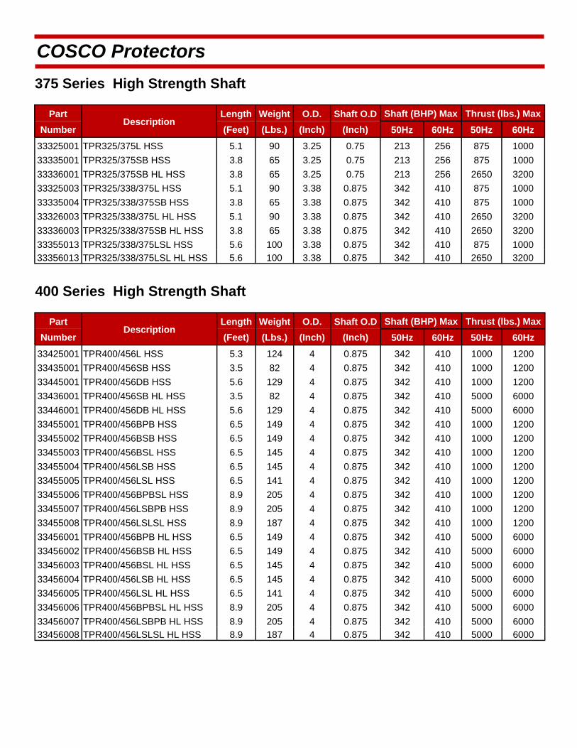
COSCO Protectors
375 Series High Strength Shaft
Part Description
Length Weight O.D. Shaft O.D Shaft (BHP) Max Thrust (lbs.) Max
Number (Feet) (Lbs.) (Inch) (Inch) 50Hz 60Hz 50Hz 60Hz
33325001 TPR325/375L HSS 5.1 90 3.25 0.75 213 256 875 1000
33335001 TPR325/375SB HSS 3.8 65 3.25 0.75 213 256 875 1000
33336001 TPR325/375SB HL HSS 3.8 65 3.25 0.75 213 256 2650 3200
33325003 TPR325/338/375L HSS 5.1 90 3.38 0.875 342 410 875 1000
33335004 TPR325/338/375SB HSS 3.8 65 3.38 0.875 342 410 875 1000
33326003 TPR325/338/375L HL HSS 5.1 90 3.38 0.875 342 410 2650 3200
33336003 TPR325/338/375SB HL HSS 3.8 65 3.38 0.875 342 410 2650 3200
33355013 TPR325/338/375LSL HSS 5.6 100 3.38 0.875 342 410 875 1000 33356013 TPR325/338/375LSL HL HSS 5.6 100 3.38 0.875 342 410 2650 3200
400 Series High Strength Shaft
Part Description
Length Weight O.D. Shaft O.D Shaft (BHP) Max Thrust (lbs.) Max
Number (Feet) (Lbs.) (Inch) (Inch) 50Hz 60Hz 50Hz 60Hz
33425001 TPR400/456L HSS 5.3 124 4 0.875 342 410 1000 1200
33435001 TPR400/456SB HSS 3.5 82 4 0.875 342 410 1000 1200
33445001 TPR400/456DB HSS 5.6 129 4 0.875 342 410 1000 1200
33436001 TPR400/456SB HL HSS 3.5 82 4 0.875 342 410 5000 6000
33446001 TPR400/456DB HL HSS 5.6 129 4 0.875 342 410 5000 6000
33455001 TPR400/456BPB HSS 6.5 149 4 0.875 342 410 1000 1200
33455002 TPR400/456BSB HSS 6.5 149 4 0.875 342 410 1000 1200
33456007 TPR400/456LSBPB HL HSS 8.9 205 4 0.875 342 410 5000 6000 33456008 TPR400/456LSLSL HL HSS 8.9 187 4 0.875 342 410 5000 6000
33455003 TPR400/456BSL HSS 6.5 145 4 0.875 342 410 1000 1200
33455004 TPR400/456LSB HSS 6.5 145 4 0.875 342 410 1000 1200
33455005 TPR400/456LSL HSS 6.5 141 4 0.875 342 410 1000 1200
33455006 TPR400/456BPBSL HSS 8.9 205 4 0.875 342 410 1000 1200
33455007 TPR400/456LSBPB HSS 8.9 205 4 0.875 342 410 1000 1200
33455008 TPR400/456LSLSL HSS 8.9 187 4 0.875 342 410 1000 1200
33456001 TPR400/456BPB HL HSS 6.5 149 4 0.875 342 410 5000 6000
33456002 TPR400/456BSB HL HSS 6.5 149 4 0.875 342 410 5000 6000
33456003 TPR400/456BSL HL HSS 6.5 145 4 0.875 342 410 5000 6000
33456004 TPR400/456LSB HL HSS 6.5 145 4 0.875 342 410 5000 6000
33456005 TPR400/456LSL HL HSS 6.5 141 4 0.875 342 410 5000 6000
33456006 TPR400/456BPBSL HL HSS 8.9 205 4 0.875 342 410 5000 6000
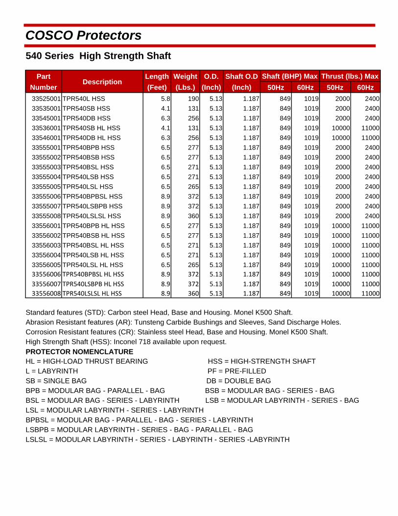
COSCO Protectors
Part Description
Length Weight O.D. Shaft O.D Shaft (BHP) Max Thrust (lbs.) Max
Number (Feet) (Lbs.) (Inch) (Inch) 50Hz 60Hz 50Hz 60Hz
33525001 TPR540L HSS 5.8 190 5.13 1.187 849 1019 2000 2400
33535001 TPR540SB HSS 4.1 131 5.13 1.187 849 1019 2000 2400
33545001 TPR540DB HSS 6.3 256 5.13 1.187 849 1019 2000 2400
33536001 TPR540SB HL HSS 4.1 131 5.13 1.187 849 1019 10000 11000
33546001 TPR540DB HL HSS 6.3 256 5.13 1.187 849 1019 10000 11000
33555001 TPR540BPB HSS 6.5 277 5.13 1.187 849 1019 2000 2400
33555002 TPR540BSB HSS 6.5 277 5.13 1.187 849 1019 2000 2400
33555003 TPR540BSL HSS 6.5 271 5.13 1.187 849 1019 2000 2400
33555004 TPR540LSB HSS 6.5 271 5.13 1.187 849 1019 2000 2400
33555005 TPR540LSL HSS 6.5 265 5.13 1.187 849 1019 2000 2400
33555006 TPR540BPBSL HSS 8.9 372 5.13 1.187 849 1019 2000 2400
33555007 TPR540LSBPB HSS 8.9 372 5.13 1.187 849 1019 2000 2400
33555008 TPR540LSLSL HSS 8.9 360 5.13 1.187 849 1019 2000 2400
33556001 TPR540BPB HL HSS 6.5 277 5.13 1.187 849 1019 10000 11000
33556002 TPR540BSB HL HSS 6.5 277 5.13 1.187 849 1019 10000 11000
33556003 TPR540BSL HL HSS 6.5 271 5.13 1.187 849 1019 10000 11000
33556004 TPR540LSB HL HSS 6.5 271 5.13 1.187 849 1019 10000 11000
33556005 TPR540LSL HL HSS 6.5 265 5.13 1.187 849 1019 10000 11000
33556006 TPR540BPBSL HL HSS 8.9 372 5.13 1.187 849 1019 10000 11000
33556007 TPR540LSBPB HL HSS 8.9 372 5.13 1.187 849 1019 10000 11000
33556008 TPR540LSLSL HL HSS 8.9 360 5.13 1.187 849 1019 10000 11000
Standard features (STD): Carbon steel Head, Base and Housing. Monel K500 Shaft. Abrasion Resistant features (AR): Tunsteng Carbide Bushings and Sleeves, Sand Discharge Holes. Corrosion Resistant features (CR): Stainless steel Head, Base and Housing. Monel K500 Shaft. High Strength Shaft (HSS): Inconel 718 available upon request.
PROTECTOR NOMENCLATURE HL = HIGH-LOAD THRUST BEARING HSS = HIGH-STRENGTH SHAFT L = LABYRINTH PF = PRE-FILLED SB = SINGLE BAG DB = DOUBLE BAG BPB = MODULAR BAG - PARALLEL - BAG BSB = MODULAR BAG - SERIES - BAG BSL = MODULAR BAG - SERIES - LABYRINTH LSB = MODULAR LABYRINTH - SERIES - BAG LSL = MODULAR LABYRINTH - SERIES - LABYRINTH BPBSL = MODULAR BAG - PARALLEL - BAG - SERIES - LABYRINTH LSBPB = MODULAR LABYRINTH - SERIES - BAG - PARALLEL - BAG LSLSL = MODULAR LABYRINTH - SERIES - LABYRINTH - SERIES -LABYRINTH
540 Series High Strength Shaft
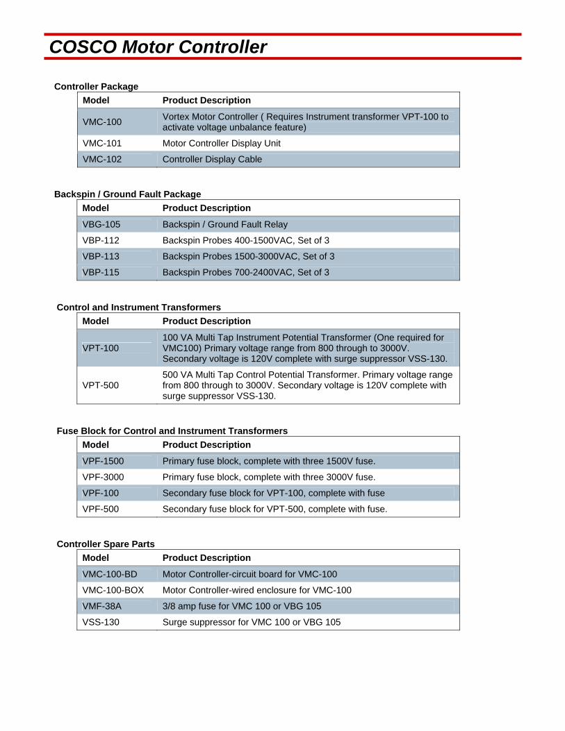
COSCO Motor Controller Controller Package
Model Product Description
VMC-100 Vortex Motor Controller ( Requires Instrument transformer VPT-100 to activate voltage unbalance feature)
VMC-101 Motor Controller Display Unit
VMC-102 Controller Display Cable
Backspin / Ground Fault Package
Model Product Description
VBG-105 Backspin / Ground Fault Relay
VBP-112 Backspin Probes 400-1500VAC, Set of 3
VBP-113 Backspin Probes 1500-3000VAC, Set of 3
VBP-115 Backspin Probes 700-2400VAC, Set of 3
Control and Instrument Transformers
Model Product Description
VPT-100 100 VA Multi Tap Instrument Potential Transformer (One required for VMC100) Primary voltage range from 800 through to 3000V. Secondary voltage is 120V complete with surge suppressor VSS-130.
VPT-500 500 VA Multi Tap Control Potential Transformer. Primary voltage range from 800 through to 3000V. Secondary voltage is 120V complete with surge suppressor VSS-130.
Fuse Block for Control and Instrument Transformers
Model Product Description
VPF-1500 Primary fuse block, complete with three 1500V fuse.
VPF-3000 Primary fuse block, complete with three 3000V fuse.
VPF-100 Secondary fuse block for VPT-100, complete with fuse
VPF-500 Secondary fuse block for VPT-500, complete with fuse.
Controller Spare Parts
Model Product Description
VMC-100-BD Motor Controller-circuit board for VMC-100
VMC-100-BOX Motor Controller-wired enclosure for VMC-100
VMF-38A 3/8 amp fuse for VMC 100 or VBG 105
VSS-130 Surge suppressor for VMC 100 or VBG 105
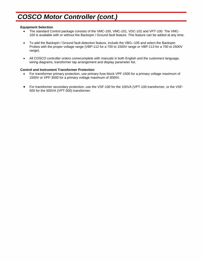
COSCO Motor Controller (cont.) Equipment Selection
The standard Control package consists of the VMC-100, VMC-101, VDC-102 and VPT-100. The VMC-100 is available with or without the Backspin / Ground fault feature. This feature can be added at any time.
To add the Backspin / Ground fault detection feature, include the VBG--105 and select the Backspin
Probes with the proper voltage range (VBP-112 for a 700 to 1500V range or VBP-113 for a 700 to 2500V range).
All COSCO controller orders comecomplete with manuals in both English and the customers language,
wiring diagrams, transformer tap arrangement and display parameter list. Control and Instrument Transformer Protection
For transformer primary protection, use primary fuse block VPF-1500 for a primary voltage maximum of 1500V or VPF-3000 for a primary voltage maximum of 3000V.
For transformer secondary protection, use the VSF-100 for the 100VA (VPT-100 transformer, or the VSF-
500 for the 500VA (VPT-500) transformer.
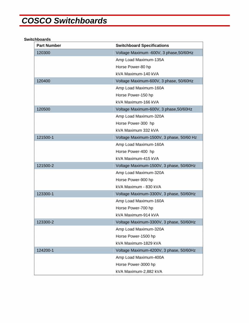
COSCO Switchboards Switchboards
Part Number Switchboard Specifications
120300 Voltage Maximum -600V, 3 phase,50/60Hz
Amp Load Maximum-135A
Horse Power-80 hp
kVA Maximum-140 kVA
120400 Voltage Maximum-600V, 3 phase, 50/60Hz
Amp Load Maximum-160A
Horse Power-150 hp
kVA Maximum-166 kVA
120500 Voltage Maximum-600V, 3 phase,50/60Hz
Amp Load Maximum-320A
Horse Power-300 hp
kVA Maximum 332 kVA
121500-1 Voltage Maximum-1500V, 3 phase, 50/60 Hz
Amp Load Maximum-160A
Horse Power-400 hp
kVA Maximum-415 kVA
121500-2 Voltage Maximum-1500V, 3 phase, 50/60Hz
Amp Load Maximum-320A
Horse Power-900 hp
kVA Maximum - 830 kVA
123300-1 Voltage Maximum-3300V, 3 phase, 50/60Hz
Amp Load Maximum-160A
Horse Power-700 hp
kVA Maximum-914 kVA
123300-2 Voltage Maximum-3300V, 3 phase, 50/60Hz
Amp Load Maximum-320A
Horse Power-1500 hp
kVA Maximum-1829 kVA
124200-1 Voltage Maximum-4200V, 3 phase, 50/60Hz
Amp Load Maximum-400A
Horse Power-3000 hp
kVA Maximum-2,882 kVA

COSCO Switchboard Features COSCO Switchboard Standard Features:
Weatherproof enclosure Nema 3R, welded construction, 12 gauge steel. White epoxy powder coat finish for outstanding corrosion protection. Separate low voltage and high voltage compartments. (1500V series and higher) Main isolation switch, load break type, spring loaded with operating handle. Vortex Motor controller Model VMC-100. The Vortex Motor Controller is microprocessor based and is
renowned for its reliability in protection and control of submersible pumps. The Vortex Motor Controller lists 116 parameters of readings and set points. Commissioning startups are simplified, as the Vortex automatically addresses the initial tem parameters. Refer to the COSCO Vortex Motor Controller Manual for more details.
Vortex Display Unit Model VMC-101 complete with VDC-102 control display cable. Current limiting fuses for heavy fault current protection. Vacuum Contractor. (1500 volt series and higher) Recording ammeter with two speed 24 hour / 7 day chart drive. Control and instrument potential transformers tapped for appropriate primary voltage range, protected with
three primary high voltage fuses and two secondary fuses. Current transformers (CTs) multi-tapped 300:5, 200:5,100:5, and 50:5 and wired to terminal strips. (This
ration multi-tap system eliminates the wrapping of heavy conductor around CTs) Hand / Off / Auto selector switch and Start push button. Control lights: red, amber and green indicating "manual", "auto start" and "run". Mechanical / electrical door interlock. Labels showing all transformer taps and external terminations. Wiring diagrams, display parameter and warning labels. Functionality tests of all features. Hi-pot test to ensure dielectric strength. Manufactured to Canadian Standards Association (CSA) Standard CSA Z-299.3. Prime source manufacturer is ISO 9002 certified.

COSCO Switchboard Features (cont.)
COSCO Switchboard Optional Features:
Vortex Backspin / Ground Fault Relay (VGB-105) with blue control light for Backspin indication.
External mount run light.
Lighting and surge arrestors.
Chemical pump package: i) Chemical pump circuit breaker or fuse. ii) Chemical pump motor starter with thermal overloads. iii) Chemical pump operation auto on/off simultaneously with submersible pump.
120 AC accessory outlet with circuit breaker or fuse.
Cold climate package: i) Space heater. ii) Thermostatic control. iii) Insulated enclosure.
Nema 4 enclosure.
Separate cable entry compartment.
Wiring for control devices other than Vortex Motor Controller.
Hubs for main cables, pressure cable and chemical pump cable.
Sun shade.
Export crating.
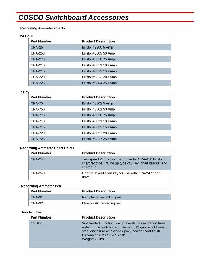
COSCO Switchboard Accessories Recording Ammeter Charts 24 Hour
Part Number Product Description
CRA-25 Bristol #3800 5 Amp
CRA-250 Bristol #3809 50 Amp
CRA-275 Bristol #3810 75 Amp
CRA-2100 Bristol #3811 100 Amp
CRA-2150 Bristol #3812 150 Amp
CRA-2200 Bristol #3813 200 Amp
CRA-2250 Bristol #3804 250 Amp
7 Day
Part Number Product Description
CRA-75 Bristol #3802 5 Amp
CRA-750 Bristol #3801 50 Amp
CRA-775 Bristol #3830 75 Amp
CRA-7100 Bristol #3831 100 Amp
CRA-7150 Bristol #3822 150 Amp
CRA-7200 Bristol #3837 200 Amp
CRA-7250 Bristol #3817 250 Amp
Recording Ammeter Chart Drives
Part Number Product Description
CRA-247 Two speed 24hr/7day chart drive for CRA-430 Bristol chart recorder. Wind up type c/w key, chart bracket and chart hub.
CRA-248 Chart hub and allen key for use with CRA-247 chart drive.
Recording Ammeter Pen
Part Number Product Description
CRA-31 Red plastic recording pen
CRA-32 Blue plastic recording pen
Junction Box
Part Number Product Description
140100 5kV Vented Junction Box, prevents gas migration from entering the switchboard. Nema 3, 12 gauge cold rolled steel enclosure with white epoxy powder coat finish Dimensions: 20 " x 20" x 10" Weight: 22 lbs

ESP Distribution Transformers
Canadian Oilwell Systems (COSCO) offers innovative design and quality manufacturing for your transformer requirements. All COSCO transformers are designed, built and tested to Canadian Standards Association (CSA) Standards C0-M1991 and ANSI standards. The prime source manufacturer is ISO 9001 certified. The COSCO Distribution transformer is designed with the following Standard Equipment:
All copper internal windings (Aluminum as option)
Vacuum oil filled, nitrogen topped, ONAN (Oil Natural, Air Natural cooling)
Covered or exposed bushings with clamp type connectors for #6 to 4/0 AWG cable (covered bushings are an option)
Completely sealed tank with tandem side mount heat exchangers for cooling
Off circuit tap arrangement of up to 25 taps for accurate secondary voltage supply to the submersible system
Channel iron skid base and lifting lugs on upper corners
Tank ground boss with connector for #6 –2/0 cable
Fill hole (1” pipe fitting with SS plug)
Nitrogen fill point
Pressure relief valve (1/4” NPT)
Oil temperature gauge (maximum indicating type)
Oil level gauge
Name plate including tap positions and all pertinent technical data
Coated with epoxy paint for corrosion protection All transformers are custom designed and built to suit specific applications. Please complete the following “ESP Transformer Design Data” form and send via fax or email.
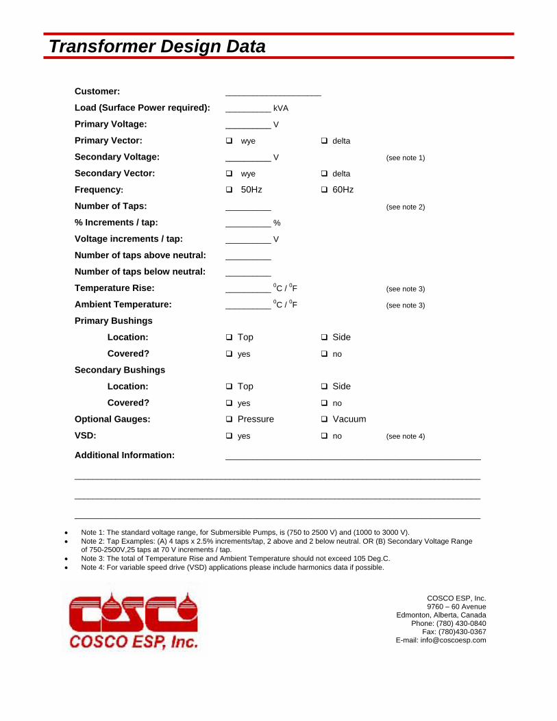
Transformer Design Data
Customer: _____________________
Load (Surface Power required): __________ kVA
Primary Voltage: __________ V
Primary Vector: wye delta
Secondary Voltage: __________ V (see note 1)
Secondary Vector: wye delta
Frequency: 50Hz 60Hz
Number of Taps: __________ (see note 2)
% Increments / tap: __________ %
Voltage increments / tap: __________ V
Number of taps above neutral: __________
Number of taps below neutral: __________
Temperature Rise: __________ 0C / 0F (see note 3)
Ambient Temperature: __________ 0C / 0F (see note 3)
Primary Bushings
Location: Top Side
Covered? yes no
Secondary Bushings
Location: Top Side
Covered? yes no
Optional Gauges: Pressure Vacuum
VSD: yes no (see note 4)
Additional Information: ________________________________________________________
_________________________________________________________________________________________
_________________________________________________________________________________________
_________________________________________________________________________________________
Note 1: The standard voltage range, for Submersible Pumps, is (750 to 2500 V) and (1000 to 3000 V). Note 2: Tap Examples: (A) 4 taps x 2.5% increments/tap, 2 above and 2 below neutral. OR (B) Secondary Voltage Range
of 750-2500V,25 taps at 70 V increments / tap. Note 3: The total of Temperature Rise and Ambient Temperature should not exceed 105 Deg.C. Note 4: For variable speed drive (VSD) applications please include harmonics data if possible.
COSCO ESP, Inc. 9760 – 60 Avenue
Edmonton, Alberta, Canada Phone: (780) 430-0840
Fax: (780)430-0367 E-mail: [email protected]
COSCO Electrical Connector Systems
COSCO offers a complete line of rugged Electric Feed-through Systems for wellheads used in Electrical
Submersible Pump Applications. COSCO connector systems represent the utmost in reliability, simplicity,
versatility, and convenience. They are adaptable to any application, onshore or offshore under any
condition.
Reliability
The lower connector is the key to the reliability of COSCO Connector Systems. Its unique design
eliminates the need for a connection in the annulus, thereby eliminating a weak spot. Corrosion resistant
stainless steel is used for the housing and flange of the connector. The compound used to insulate the
electric conductors and provide the pressure seal inside the body of the connector is not susceptible to
swelling or breakdown caused by wellbore fluids. The unique construction of the connector includes a
Torlon face block to protect against pressure damage.
Ease of Installation
The lower connector bolts to the bottom of the tubing hanger by means of a flange. The upper connector
bolts to the top of the tubing hanger and the connection between the upper and lower connectors is made
within the electrical connection port of the tubing hanger. The lower connector pigtail is spliced to the
down hole power cable. No special tools are required for installation.
Versatility
Several different configurations are available to meet any need:
Two-piece 90-degree top entry
Three-piece 90-degree top entry
Side entry systems
Fail safe systems
A variety of pigtail cable types and sizes are available to meet any application or service.
Low Profile Design
All COSCO connector systems allow a lower profile tree assembly. The side entry system is specifically
designed for applications where low tree profiles are critical, such as offshore applications.
Existing Wellheads
COSCO connectors can be installed in most existing wellhead equipment to convert for use with
submersible pumps or to replace other types of electric feed-through systems.

Two Piece 900Top Entry Connector Systems
Top entry connector systems are used to convert existing wellheads for use with electrical submersible pumps or to replace existing electric feed-through systems. COSCO “Universal” tubing head adapters also use the top entry system. The two piece, top entry system is used where a tubing adapter (bonnet) is not required. It consists of a 90-degree upper connector and a lower connector. The lower connector bolts to the bottom of the tubing hanger and the upper connector bolts to the top of the tubing hanger. The connection between the two connectors is made within the electrical connection port of the tubing hanger. In this configuration, the tubing hanger remains exposed in the top of the tubing head spool. To convert existing wellheads to the two piece, top entry system, it is required to change out the tubing hanger.
2-140
2-137
2-141
2-137
O-Ring Guide
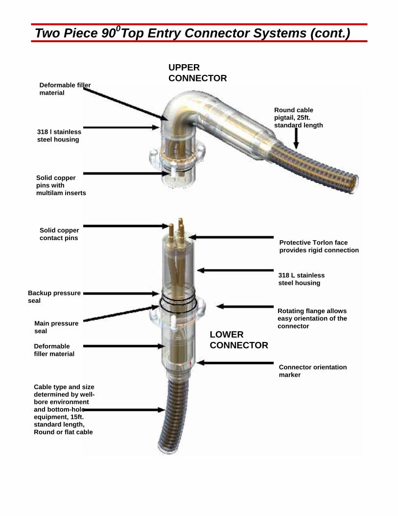
Two Piece 900Top Entry Connector Systems (cont.)
Backup pressure seal
Deformable filler material
Deformable filler material
318 l stainless steel housing
Solid copper pins with multilam inserts
Solid copper contact pins
Main pressure seal
Cable type and size determined by well-bore environment and bottom-hole equipment, 15ft. standard length, Round or flat cable
Connector orientation marker
Rotating flange allows easy orientation of the connector
318 L stainless steel housing
Protective Torlon face provides rigid connection
Round cable pigtail, 25ft. standard length
UPPER CONNECTOR
LOWER CONNECTOR

Three Piece 900Top Entry Connector Systems
The three piece, top entry system is used where a tubing adapter (bonnet) is required. In addition to the upper and lower connectors, a transmission element is used to provide the required extra length to extend through the bonnet (as shown to the right). To convert existing wellheads to the three piece, top entry system, it is required to change out the tubing hanger and bonnet.
Transmission Element
Upper Connector
Lower Connector
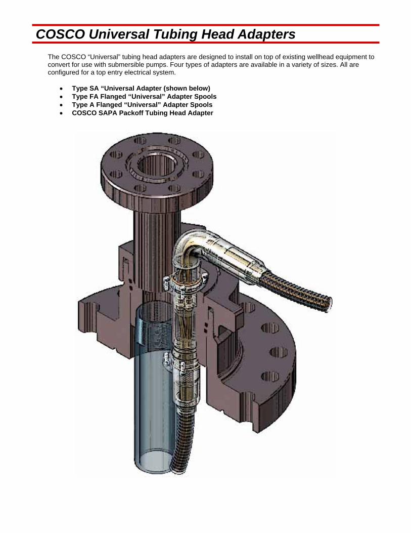
COSCO Universal Tubing Head Adapters
The COSCO “Universal” tubing head adapters are designed to install on top of existing wellhead equipment to convert for use with submersible pumps. Four types of adapters are available in a variety of sizes. All are configured for a top entry electrical system.
Type SA “Universal Adapter (shown below) Type FA Flanged “Universal” Adapter Spools Type A Flanged “Universal” Adapter Spools COSCO SAPA Packoff Tubing Head Adapter
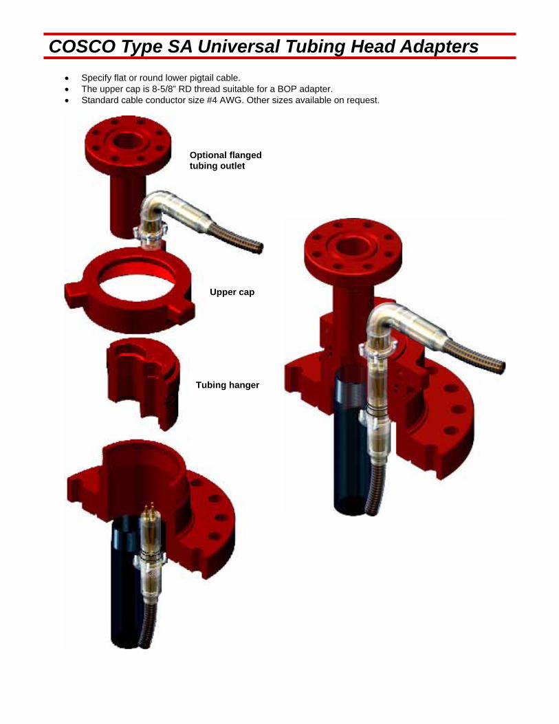
COSCO Type SA Universal Tubing Head Adapters
Specify flat or round lower pigtail cable. The upper cap is 8-5/8” RD thread suitable for a BOP adapter. Standard cable conductor size #4 AWG. Other sizes available on request.
Optional flanged tubing outlet
Upper cap
Tubing hanger
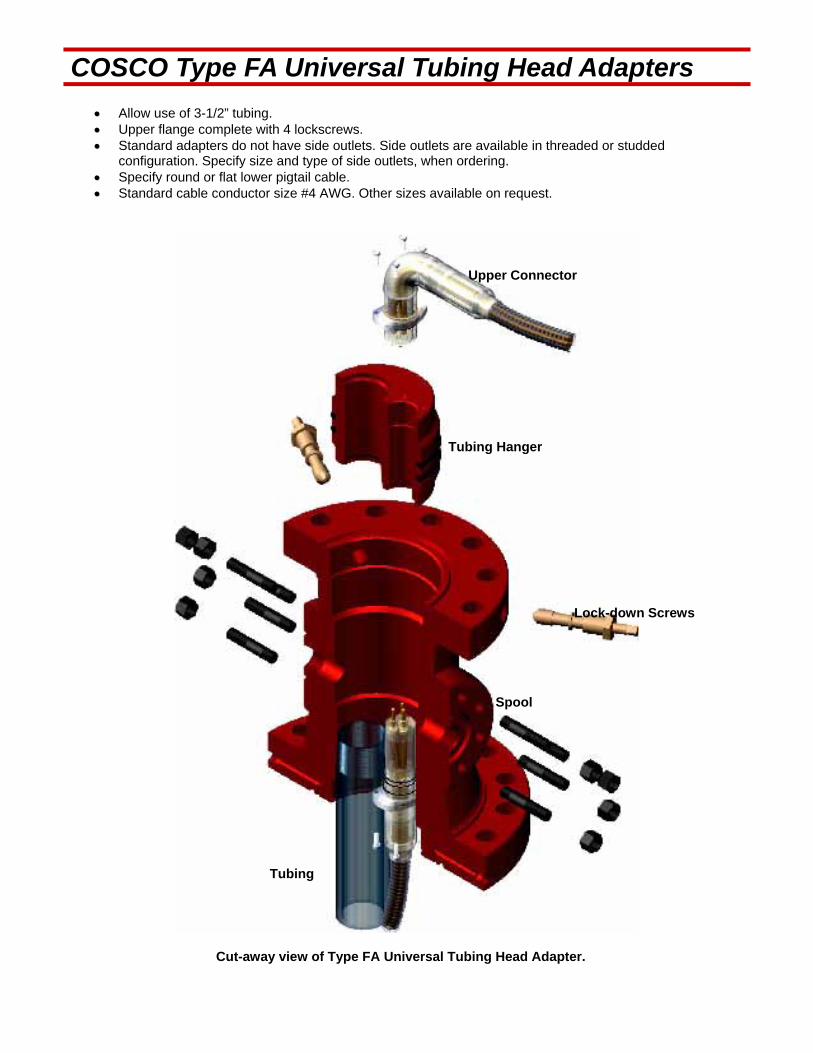
COSCO Type FA Universal Tubing Head Adapters
Allow use of 3-1/2” tubing. Upper flange complete with 4 lockscrews. Standard adapters do not have side outlets. Side outlets are available in threaded or studded
configuration. Specify size and type of side outlets, when ordering. Specify round or flat lower pigtail cable. Standard cable conductor size #4 AWG. Other sizes available on request.
Tubing Hanger
Lock-down Screws
Upper Connector
Spool
Tubing
Cut-away view of Type FA Universal Tubing Head Adapter.
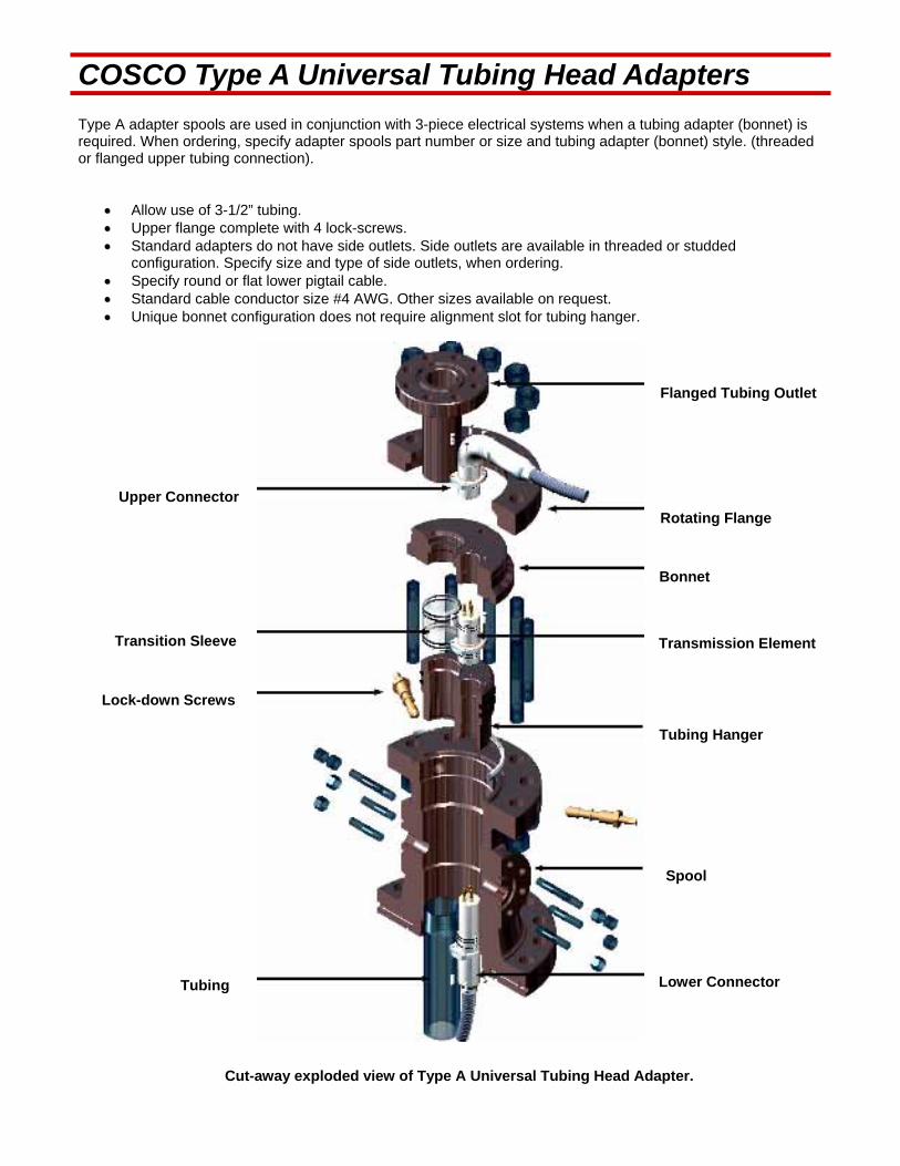
COSCO Type A Universal Tubing Head Adapters Type A adapter spools are used in conjunction with 3-piece electrical systems when a tubing adapter (bonnet) is required. When ordering, specify adapter spools part number or size and tubing adapter (bonnet) style. (threaded or flanged upper tubing connection).
Allow use of 3-1/2” tubing. Upper flange complete with 4 lock-screws. Standard adapters do not have side outlets. Side outlets are available in threaded or studded
configuration. Specify size and type of side outlets, when ordering. Specify round or flat lower pigtail cable. Standard cable conductor size #4 AWG. Other sizes available on request. Unique bonnet configuration does not require alignment slot for tubing hanger.
Lower Connector
Flanged Tubing Outlet
Spool
Rotating Flange
Tubing Hanger
Transmission Element
Bonnet
Tubing
Lock-down Screws
Transition Sleeve
Upper Connector
Cut-away exploded view of Type A Universal Tubing Head Adapter.
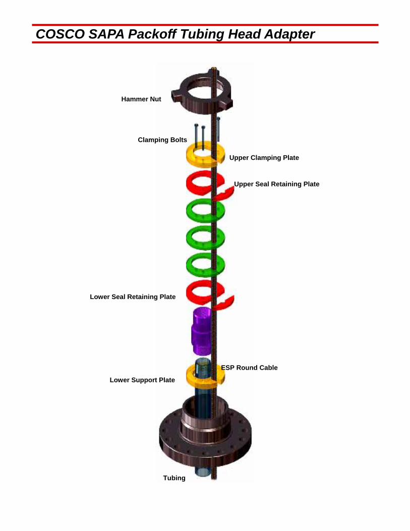
COSCO SAPA Packoff Tubing Head Adapter
Upper Clamping Plate
Hammer Nut
ESP Round Cable
Lower Seal Retaining Plate
Lower Support Plate
Tubing
Upper Seal Retaining Plate
Clamping Bolts
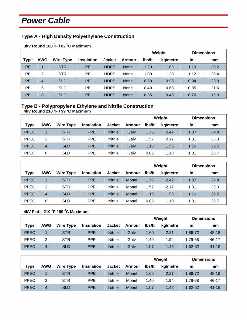
Power Cable Type A - High Density Polyethylene Construction 3kV Round 180 0F / 82 0C Maximum
Weight Dimensions
Type AWG Wire Type Insulation Jacket Armour lbs/ft kg/metre in. mm
PE 1 STR PE HDPE None 1.20 1.66 1.19 30.2
PE 2 STR PE HDPE None 1.00 1.38 1.12 28.4
PE 4 SLD PE HDPE None 0.69 0.95 0.94 23.9
PE 6 SLD PE HDPE None 0.49 0.68 0.85 21.6
PE 8 SLD PE HDPE None 0.35 0.48 0.76 19.3
Type B - Polypropylene Ethylene and Nitrile Construction 4kV Round 210 0F / 99 0C Maximum
Weight Dimensions
Type AWG Wire Type Insulation Jacket Armour lbs/ft kg/metre in. mm
PPEO 1 STR PPE Nitrile Galv 1.75 2.42 1.37 34.8
PPEO 2 STR PPE Nitrile Galv 1.57 2.17 1.31 33.3
PPEO 4 SLD PPE Nitrile Galv 1.13 1.56 1.16 29.5
PPEO 6 SLD PPE Nitrile Galv 0.85 1.18 1.01 25.7
Weight Dimensions
Type AWG Wire Type Insulation Jacket Armour lbs/ft kg/metre in. mm
PPEO 1 STR PPE Nitrile Monel 1.75 2.42 1.37 34.8
PPEO 2 STR PPE Nitrile Monel 1.57 2.17 1.31 33.3
PPEO 4 SLD PPE Nitrile Monel 1.13 1.56 1.16 29.5
PPEO 6 SLD PPE Nitrile Monel 0.85 1.18 1.01 25.7
4kV Flat 210 0F / 99 0C Maximum
Weight Dimensions
Type AWG Wire Type Insulation Jacket Armour lbs/ft kg/metre in. mm
PPEO 1 STR PPE Nitrile Galv 1.60 2.21 1.89-72 48-18
PPEO 2 STR PPE Nitrile Galv 1.40 1.94 1.79-68 46-17
PPEO 4 SLD PPE Nitrile Galv 1.07 1.48 1.62-62 41-16
Weight Dimensions
Type AWG Wire Type Insulation Jacket Armour lbs/ft kg/metre in. mm
PPEO 1 STR PPE Nitrile Monel 1.60 2.21 1.89-72 48-18
PPEO 2 STR PPE Nitrile Monel 1.40 1.94 1.79-68 46-17
PPEO 4 SLD PPE Nitrile Monel 1.07 1.48 1.62-62 41-16
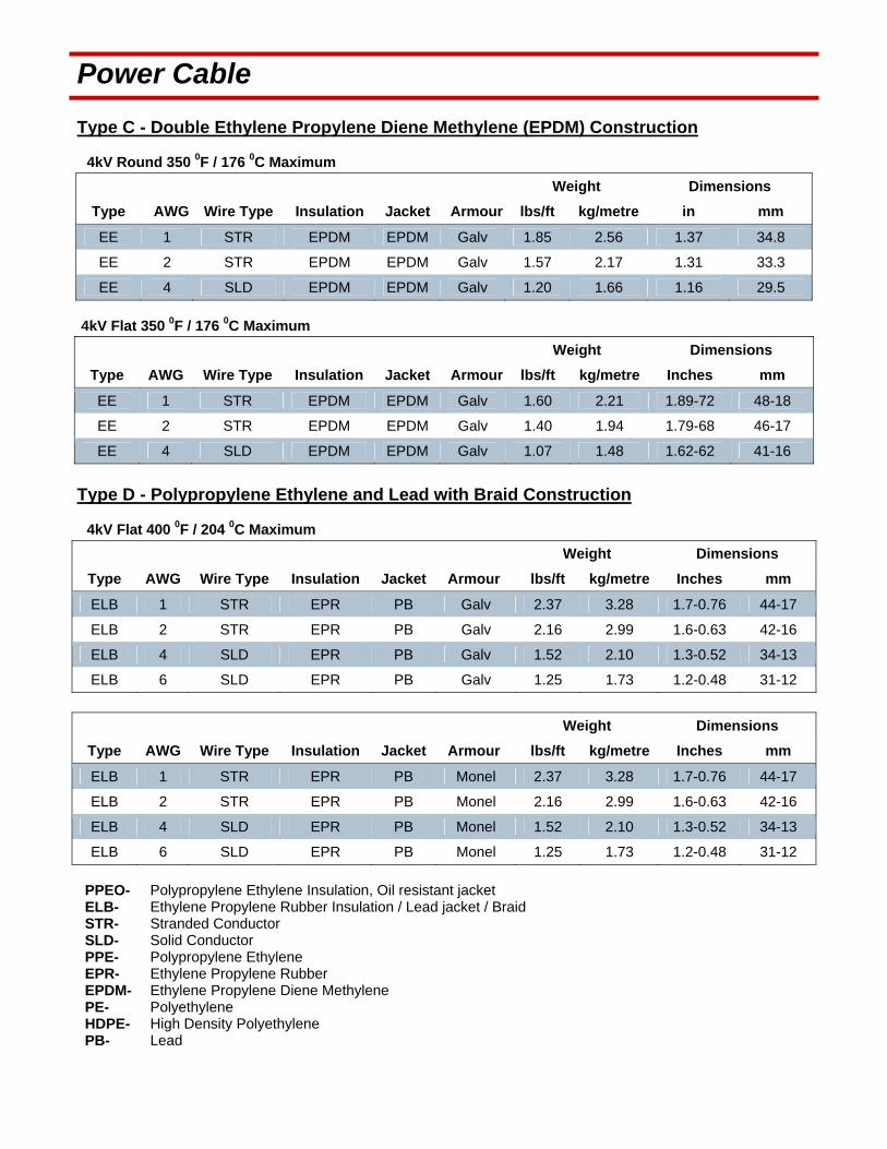
Power Cable
Type C - Double Ethylene Propylene Diene Methylene (EPDM) Construction 4kV Round 350 0F / 176 0C Maximum
Weight Dimensions
Type AWG Wire Type Insulation Jacket Armour lbs/ft kg/metre in mm
EE 1 STR EPDM EPDM Galv 1.85 2.56 1.37 34.8
EE 2 STR EPDM EPDM Galv 1.57 2.17 1.31 33.3
EE 4 SLD EPDM EPDM Galv 1.20 1.66 1.16 29.5
4kV Flat 350 0F / 176 0C Maximum
Weight Dimensions
Type AWG Wire Type Insulation Jacket Armour lbs/ft kg/metre Inches mm
EE 1 STR EPDM EPDM Galv 1.60 2.21 1.89-72 48-18
EE 2 STR EPDM EPDM Galv 1.40 1.94 1.79-68 46-17
EE 4 SLD EPDM EPDM Galv 1.07 1.48 1.62-62 41-16
Type D - Polypropylene Ethylene and Lead with Braid Construction 4kV Flat 400 0F / 204 0C Maximum
Weight Dimensions
Type AWG Wire Type Insulation Jacket Armour lbs/ft kg/metre Inches mm
ELB 1 STR EPR PB Galv 2.37 3.28 1.7-0.76 44-17
ELB 2 STR EPR PB Galv 2.16 2.99 1.6-0.63 42-16
ELB 4 SLD EPR PB Galv 1.52 2.10 1.3-0.52 34-13
ELB 6 SLD EPR PB Galv 1.25 1.73 1.2-0.48 31-12
Weight Dimensions
Type AWG Wire Type Insulation Jacket Armour lbs/ft kg/metre Inches mm
ELB 1 STR EPR PB Monel 2.37 3.28 1.7-0.76 44-17
ELB 2 STR EPR PB Monel 2.16 2.99 1.6-0.63 42-16
ELB 4 SLD EPR PB Monel 1.52 2.10 1.3-0.52 34-13
ELB 6 SLD EPR PB Monel 1.25 1.73 1.2-0.48 31-12
PPEO- Polypropylene Ethylene Insulation, Oil resistant jacket ELB- Ethylene Propylene Rubber Insulation / Lead jacket / Braid STR- Stranded Conductor SLD- Solid Conductor PPE- Polypropylene Ethylene EPR- Ethylene Propylene Rubber EPDM- Ethylene Propylene Diene Methylene PE- Polyethylene HDPE- High Density Polyethylene PB- Lead

Cable Accessories Cable Reels-Steel
Normal size 50” 60” 78” 85” 90”
Flange Diameter
Inches 50 66 78 85 90
mm 1270 1676 1981 2159 2286
Drum Diameter
inches 30 36 42 42 42
mm 762 914 1067 1067 1067
Traverse Width
inches 40 40 57 57 57
mm 1016 1016 1448 1448 1448
Overall Width
inches 46 46 64 64 64
mm 1168 1168 1626 1626 1626
Weight lbs 335 460 811 975 1064
kg 152 209 368 442 483
Cable Clamps Saddles
Cable Type Length Weight
Inches mm lbs kg’s
#6 Armour -#8 NO Armour 2 51 0.06 0.03
#4 Armour -#6 NO Armour 2 51 0.08 0.04
#2 Armour -#4 NO Armour 2 51 0.09 0.04
#1 Armour -#2 NO Armour 2 51 0.10 0.05
Flat Cable Guard
Material Length Weight
Feet Metres lbs kg’s
Galvanized Carbon Steel 9.6 3 8 3.4
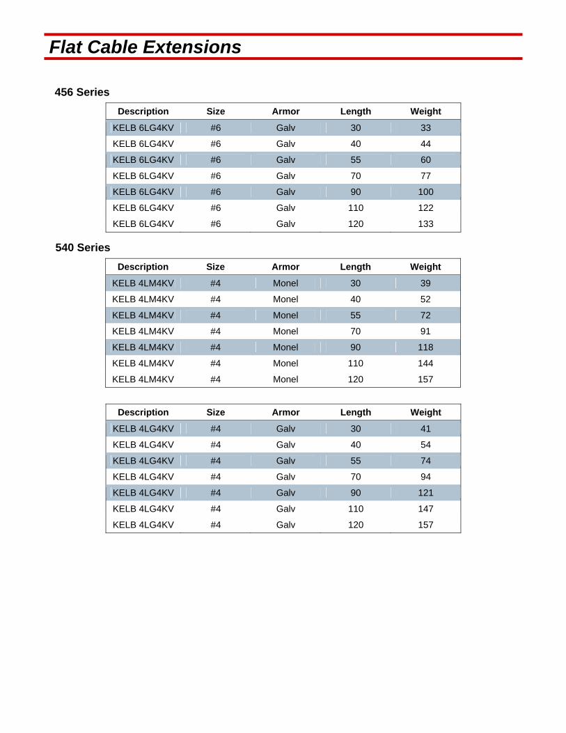
Flat Cable Extensions 456 Series
Description Size Armor Length Weight
KELB 6LG4KV #6 Galv 30 33
KELB 6LG4KV #6 Galv 40 44
KELB 6LG4KV #6 Galv 55 60
KELB 6LG4KV #6 Galv 70 77
KELB 6LG4KV #6 Galv 90 100
KELB 6LG4KV #6 Galv 110 122
KELB 6LG4KV #6 Galv 120 133
540 Series
Description Size Armor Length Weight
KELB 4LM4KV #4 Monel 30 39
KELB 4LM4KV #4 Monel 40 52
KELB 4LM4KV #4 Monel 55 72
KELB 4LM4KV #4 Monel 70 91
KELB 4LM4KV #4 Monel 90 118
KELB 4LM4KV #4 Monel 110 144
KELB 4LM4KV #4 Monel 120 157
Description Size Armor Length Weight
KELB 4LG4KV #4 Galv 30 41
KELB 4LG4KV #4 Galv 40 54
KELB 4LG4KV #4 Galv 55 74
KELB 4LG4KV #4 Galv 70 94
KELB 4LG4KV #4 Galv 90 121
KELB 4LG4KV #4 Galv 110 147
KELB 4LG4KV #4 Galv 120 157

Check Valves / Bleeders Common construction is carbon steel. Check and Bleeder valves are available in corrosion resistant metals such as stainless steel and Monel.
Please inquire for prices and delivery information. Check Valves
Length Weight Type/Size Part Number mm in. kg lb 2"OD 10rd EUE tubing 15 6 3 6 2 3/8"OD 8rd EUE tubing 18 7 4 8 2 3/8" OD 10rd reg tubing 18 7 4 8 2 7/8" OD 8rd EUE tubing 18 7 5 12 3 1/2" OD 8rd EUE tubing 20 8 8 18 3 1/2" OD 10rd reg tubing 20 8 8 18 4 1/2" OD 8rd EUE tubing 20 8 11 24 4 1/2" OD 8rd reg tubing 20 8 11 24 5 1/2" OD 8rd casing 33 13 14 30 6 5/8" OD 8rd casing 36 14 20 45 7" OD 8rd casing 51 20 37 81
Bleeder Valves
Type/Size Part Number Length Weight mm in. kg lb 2 7/8" OD 8rd EUE tubing 15 6 3 6 2 7/8" OD 10rd EUE tubing 18 7 4 8 3 1/2" OD 8rd EUE tubing 18 7 4 8 3 1/2" OD 10rd reg tubing 18 7 5 12
Check and Bleeder Valves
Type/Size Part Number Length Weight mm in. kg lb 2 3/8" OD 8rd EUE tubing 15 6 3 6 2 7/8" OD 8 rd EUE tubing 18 7 4 8 3 1/2" OD 8rd EUE tubing 18 7 4 8 4 1/2" OD 8d EUE tubing 18 7 5 12 4 1/2" OD 8rd reg tubing 20 8 8 18 5 1/2" OD 8rd casing 20 8 8 18 6 5/8" OD 8rd casing 20 8 11 24 7" OD 8rd casing 20 8 11 24 8 5'8" 8rd casing 33 13 14 30
For 3.5 E.U.E. 8 RD
Every check Valve and Drain Valve comes with a Quality Assurance sheet with 100% tracability on all manufactured parts.
Tracability is direct to the mill. Mill specs can be provided.
All E.U.E. 8RD Threads are gauged to API Spec 5b with certified guages.
Valve Bodies are of a 4130 HR Steel. Internal components are a 303 Stainless Steel. The Monel Break-off Plug is a K- 400 specification.
All Check and Drain Valves are Phosphate Coated for added corrosion resistance.
Drain valves come standard with Brass Break-off Plugs.
All parts are manufactured in Canada and meet NACE Specifications.
All Check and Drain Valves come with Thread Protection.
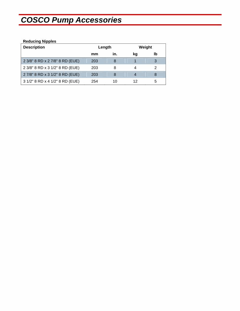
COSCO Pump Accessories Reducing Nipples
Description Length Weight
mm in. kg lb
2 3/8" 8 RD x 2 7/8" 8 RD (EUE) 203 8 1 3
2 3/8" 8 RD x 3 1/2" 8 RD (EUE) 203 8 4 2
2 7/8" 8 RD x 3 1/2" 8 RD (EUE) 203 8 4 8
3 1/2" 8 RD x 4 1/2" 8 RD (EUE) 254 10 12 5
Standing Valve - Reverse Flow Regulator Surface Wireline Retrievable
Length Weight
Description mm Inches Kg’s Lbs
2 3/8" Standing Valve 480 18.7 4.5 10
2 3/8 Landing Nipple 235 9.3 5.9 13
2 7/8" Standing Valve 480 18.7 5.5 12
2 7/8" Landing Nipple 235 9.3 6.4 14
3 1/2" Standing Valve 480 18.7 6.8 15
3 1/2" Landing Nipple 235 9.3 6.8 15
4 1/2" Landing Nipple 480 18.7 7.7 17
2" JDC Pulling Tool 235 9.3 7.3 16
( for 2 3/8" and 2 7/8" Valve) 445 17.5 6.4 14
2 1/2" JDC Pulling Tool ( for 3 1/2" and 4 1/2" Valve ) 457 18 6.8 15
All valves equipped with Teflon MOLY ‘V’ packing rings. All valves are stainless steel. ( 316 ) Nipples available in stainless steel or L-80 phosphate steel.

" WJ" Standing Valve A. Retrieve Procedure: Standard wireline tools ( stem & jars ) 1. Use appropriate pull tool: 2" reg. - 2" Camco JDC or Otis SB 2 1/2" reg. - 2" Camco JDC or Otis SB 3" reg. - 2 1/2" Camco JDC or Otis SB 4 1/2" reg. - 3" Camco JDC or Otis SB 2. Latch onto fish neck c/w proper wireline tools. Pull equalizing stem off seat and hold until valve is equalized. Pull valve to surface. B. To Service Regulator: Body built in three sections: top, center,lower. 1. Break top section to check valve and seat surface. 2. Break lower section replace packing. C. Running Procedure 1. Using proper sized JDC or Otis SB running-pulling tool and wireline tool string; run onto well-bore, jar into WJ seating nipple and shear off. NOTE: - Standard "WJ" valve manufactured from 316 SS. - Standard "WJ" seating nipple manufactured from C-75 or L-80 material. - Other materials such as Monel K-500 or Incoloy 925 on request.
STANDARD SIZE FISHING NECK ADAPTSTO POPULAR PULLING TOOLS
SET SCREW LOCK PREVENTS BACK OFF
SIX SIDED STEM ASSURES CONSISTENTSEATING CONTACT
METAL TO METAL SEAT FOR RELIABLESEALING
SMOOTHLY CONTOURED SEALING SURFACEMINIMIZES FLUID WASHING
POSITIVE STOP NO-GO SHOULDER
FOUR LARGE FLOW WINDOWS FORUNRESTRICTED FLUID FLOW ANDQUICK EQUALIZATION
RELIABLE CHEVRON PACKING PROVIDESCOMPETENT HIGH PRESSURE SEALINGAND READILY AVAILABLE REPLACEMENTSEALS
COLLECT HOLD DOWN PROVIDES APOSITIVE YET SIMPLE LOCKINGMECHANISM