subdivision construction plan application instructions · subdivision construction plan application...
TRANSCRIPT
CITY OF AUSTIN Development Services Department One Texas Center | Phone: 512.978.4000 505 Barton Springs Road, Austin, Texas 78704
Subdivision Construction Plan Application Instructions The following information outlines the Application Instructions and Submittal Requirements necessary to obtain a subdivision construction plan permit within the City of Austin jurisdiction (full-purpose, limited-purpose city limits, and extraterritorial jurisdiction ETJ). The regulatory requirements and procedures for approval are defined in Volume III, Chapter 25 of the City of Austin Land Development Code (LDC) and Volume IV, Title 30.
Chapter 25 and Title 30 were adopted by City Council in order to protect the health, safety and welfare of the Austin community. If a project is in the ETJ, the city and the county will provide a joint review.
Additional information about the subdivision construction plan permitting process and code requirements can be obtained prior to submitting a subdivision construction plan application by contacting the Development Assistance Center (DAC) at One Texas Center, 505 Barton Springs Road, phone (512) 978-4000, or by visiting the City of Austin’s Development website at http://www.austintexas.gov/development.
The City of Austin encourages people considering a subdivision to request a Development Assessment to determine plat/plan requirements, project feasibility, and permitting requirements. For information, please see Subdivision Construction Plan Overview and Review Procedures at http://www.austintexas.gov/page/land-use-applications#sub.
Application Instructions
The application must be complete and accurate prior to submittal. Please refer to the descriptions below to ensure all information is entered correctly. To access the application, please see Subdivision Construction Plan Application at http://www.austintexas.gov/page/land-use-applications#sub. Note that the application is a fillable PDF, and must first be SAVED TO COMPUTER to be completed.
All information is required (if applicable).
Section 1: Project Information Subdivision Name Provide the name of the proposed subdivision.
Subdivision Street Location Provide the street address of the project, or distance from nearest intersection. For assistance, call: (512) 974-2797; or email: [email protected].
Section 2: Applicant/Agent Information Provide all contact information. If an agent is designated, this is considered the “Applicant” and will be the primary contact.
City of Austin | Subdivision Construction Plan Application Instructions rev 7/19/2016 | Page 1 of 28
Section 3: Owner Information Provide all contact information if the owner is not the applicant. The current owner must sign the application or attach a written authorization for the agent. Be sure all signatures are legible and address information is correct.
Section 4: Engineer Information Provide all engineer contact information, if applicable.
Section 5: Other Professional/Trade Information Provide all professional and/or trade contact information, if applicable. Examples include general contractor, electrical contractor, landscape architect, etc.
Section 6: Property Attributes To determine the following information, refer to the GIS Viewer on the Development website at http://www.austintexas.gov/GIS/DevelopmentWebMap/:
• Watershed• Watershed Classification• Recharge Zone• Land Development Jurisdiction• County
School District Provide the name of the school district that this project is located within.
Municipal Utility District Provide the name of the Municipal Utility District if applicable.
Tax Parcel Number(s) These numbers may be found on the tax plats or tax certificates you are providing. The Intake Center or Document Sales Window can assist you with these numbers.
Electric Utility Provider Provide the name of the electric utility provider.
Water Provider Provide the name of the water provider.
Wastewater/Sewage Disposal Provider Provide the name of the wastewater/sewage disposal provider, or indicate if an on-site septic system is proposed.
Development Assessment (refer to Subdivision Construction Plan Overview and Review Procedures at http://www.austintexas.gov/page/land-use-applications#sub for more information) If you have received a Development Assessment, indicate the file number and the Intake Center will apply the credit associated with the assessment to your application fee. The assessment credit is void if not used within six months.
Section 7: Related Cases Provide the file numbers which relate to applications on this property that have been filed in the past.
City of Austin | Subdivision Construction Plan Application Instructions rev 7/19/2016 | Page 2 of 28
Section 8: Proposed Land Use Select the proposed land use for each lot, and state the number of lots, units (if multifamily), and acreage.
Section 9: Submittal Verification Ensure all information entered in the application is complete and accurate before signing.
Section 10: Inspection Authorization Provide permission for inspection of the property as part of the application process.
Section 11: Acknowledgement Form concerning subdivision plat note/deed restrictions The applicant should carefully check these records before signing the Acknowledgment Form. Plat notes are shown on the face of the subdivision plat. Plats are available at the City or the Courthouse. Deed restrictions are recorded at the Courthouse, if you do not have them in your possession.
Submittal Requirements
In addition to completing the Subdivision Construction Plan Application, the following information will be required to complete the subdivision approval process. For details, refer to the complete Exhibits on the pages that follow.
Exhibit I: Engineer’s Summary Letter Exhibit II: Geotechnical Investigation Report Exhibit III: Construction Plan Requirements
A. Cover Sheet B. Final Plat C. General Construction Notes D. Drainage Area Map Sheets E. Street Plan and Profile Sheets F. Drainage Plan and Profile Sheets G. Detention Plan H. Water Quality Plan I. Pavement Striping and Signs Plan J. Construction Details
Exhibit IV: Environmental Submittal Requirements Exhibit V: Electronic Submittal Exhibit VI: Environmental Resource Inventory – Critical Environmental Feature Worksheet
PLEASE NOTE ................................................................. Exhibits V and VI are fillable forms that can be completed electronically. To ensure your information is saved, click here to Save this document to your computer, then open your copy and continue.
The Tab key may be used to navigate to each field; Shift + Tab moves to the previous field. The Enter key activates links, emails, and buttons. Use the Up & Down Arrow keys to scroll through drop-down lists and check boxes, and hit Enter to make a selection.
City of Austin | Subdivision Construction Plan Application Instructions rev 7/19/2016 | Page 3 of 28
Additional Requirements
1. VariancesWhen requesting a variance, please include in the Engineer’s Summary Letter (Exhibit I) adescription of the variance and justification, and the applicable ordinance and section.
2. Tax PlatsIf a variance is being requested, provide one blueline copy of each of the current tax plats,showing all properties within 500 feet of the tract or limits of construction. Include all mapsreferenced within the 500 feet. Outline the tract or limits of construction in red. (DO NOT SPLICEMAPS TOGETHER)
• Tax plats are available at the Travis Central Appraisal District, Walnut Creek BusinessPark, 8314 Cross Park Drive, Austin (Hwy 290 East and Cross Park Drive), phone: (512)834-9138
• Tax plats for Travis County may be printed online at http://www.traviscad.org/
For projects located outside of Travis County, submit a list of names and addresses of all property owners within a 500-foot radius of the tract.
3. Tax CertificateTax certificates must be submitted with all construction plan applications.
• Tax certificates may be obtained from the Travis County Tax Office located in theCourthouse Annex, 5501 Airport Blvd., Austin
The tax certificate should indicate that there are no taxes owed.
4. Location MapIf a variance is being requested, provide a 4" x 4" location map on a separate 8-1/2" x 11" sheet. Itshould be centered on the sheet, have a North arrow, and note “not to scale.”
5. FeesFee schedules are available at the Development Assistance Center.
6. Engineer’s Summary Letter (Exhibit I)Provide an original and three copies
7. Geotechnical Investigation Report (Exhibit II)Submit two copies. This report may be submitted at a later date but no later than the submittal ofplans for the first update review.
8. Construction Plans (Requirements - Exhibit III)Eight complete, folded, 24” x 36” sets of construction plans are required. Nine sets are required ifthe project is on a state highway.
Note: After approval of the construction plans, six full-size sets and one half-size set of the signedplans shall be submitted before the site development permit can be released.
City of Austin | Subdivision Construction Plan Application Instructions rev 7/19/2016 | Page 4 of 28
9. Traffic Control PlanNine copies of a Traffic Control Plan must be included if the construction is in an existing right-of-way. Ten copies if the project is on a state highway.
10. Pavement Striping PlanIf pavement striping is proposed, ten copies of a striping plan is required. Eleven copies if theproject is on a state highway.
11. Engineering ReportTwo copies shall be submitted with the application and shall include the following:
• Table of contents with index and tabbed appendices• Source of floodplain information (calculations where applicable)• Calculations supporting adequacy of existing and proposed on-site channels, storm
sewers, and drainage structures• Calculations supporting adequacy of detention pond size• Calculations for floodplain modifications and cross sections• Summary assessment of impact on adjacent properties and drainage structures• Signature and seal of professional engineer on report• Calculations of existing and fully developed flows• Calculations of off-site flows• Calculations of capacity of drainage facilities on adjacent properties affecting hydraulic
performance in the subdivision• A final report reflecting all changes done during review must be submitted for the
case file after all comments have been addressed
12. County ApprovalFor projects outside of the Austin City Limits, release of the construction plans by thecorresponding county shall be in accordance with Chapter 25 and Title 30 of City of Austin LandDevelopment Code and the single office of Travis County and the City of Austin.
City of Austin | Subdivision Construction Plan Application Instructions rev 7/19/2016 | Page 5 of 28
Exhibit I: Engineer’s Summary Letter
No construction plans will be accepted unless accompanied by a summary letter signed and sealed by the same registered Texas professional engineer who sealed the construction plans. Summary letters for small projects do not require an engineer unless slopes or trenches exceed five feet (see Sec. 25-5-3 of the City of Austin LDC).
The summary letter should describe the proposed development and might include, but not limited to, the following:
Acreage to be developed Watershed in which project is located Type of development Explanation of any proposed project phasing Methods to be used for handling stormwater runoff – i.e., drainage easements, channels, curb
inlets, storm sewers, detention, sedimentation and filtration ponds, water quality control methods, etc.
Effect the proposed development will have on existing and future drainage systems in the area and on the natural and traditional character of the land and waterways
Justification for exemption from the Watershed Protection Regulations Address the applicable sections of the LDC Address dam safety and landfill certification requirements Include Variance request and a description of the variance and justification, and the applicable
ordinance and section
<< Back to Exhibits
City of Austin | Subdivision Construction Plan Application Instructions rev 7/19/2016 | Page 6 of 28
Exhibit II: Geotechnical Investigation Report
Two copies of the Geotechnical Investigation Report shall be furnished for the initial review of the plans.
Pavement design shall be based on City of Austin Procedures for Street Paving Thickness Design (Subdivision Memorandum E-78-3 from Public Works Department) or the Municipal Pavement Structural Design and Life-Cycle Cost Analysis System (MFPS-1/MRPS-1)
For projects located within the Edwards Aquifer Recharge Zone and the Barton Springs Zone, address pond liner requirements in a QA/QC plan
Show legible professional engineer’s seal and signature
<< Back to Exhibits
City of Austin | Subdivision Construction Plan Application Instructions rev 7/19/2016 | Page 7 of 28
Exhibit III: Construction Plan Requirements
A. COVER SHEET - Show the following: Subdivision name on cover sheet in one-half inch or larger letters (use same name as on the
final plat) Legal description of property (lots, block, subdivision name) Name, address, and telephone number of owner and engineering firm preparing plans Subdivision file number Name of watershed Project location map that clearly indicates precise location of the tract (4” x 4” minimum) with
north arrow Texas Department of Transportation stationing, for streets intersecting or adjacent to state
maintained roadways Tabulation sheet index Legible professional engineer’s seal and signature List all granted variances/waivers from Design Criteria and/or City of Austin Land Development
Code (LDC)
NOTES One of the following notes:
This project complies with the Watershed Protection Regulations in Chapters 25-7 and 25-8 of the LDC; – OR –This project is EXEMPT from the provisions of 25-8 of the LDC.
The following notes:
"Release of this application does not constitute a verification of all data, information and calculations supplied by the applicant. The engineer of record is solely responsible for the completeness, accuracy and adequacy of his/her submittal, whether or not the application is reviewed for code compliance by City engineers."
When applicable, add the following certification to the cover sheet (DCM 8.3.4.B.3): “I [name of professional engineer] Texas license number [number] certify that the design of the dam in this set of plans can safely pass 75 percent of the Probable Maximum Flood based on the hydrologic, hydraulic, structural and geotechnical analysis using standard accepted engineering practices.”
“All responsibility for the adequacy of these plans remains with the Engineer who prepared them. In approving these plans, the City of Austin must rely upon the adequacy of the work of the Design Engineer.”
Applicable City of Austin General Construction Notes for subdivision construction Tabulation of applicable Special Notes Construction Sequencing
City of Austin | Subdivision Construction Plan Application Instructions rev 7/19/2016 | Page 8 of 28
APPROVAL BLOCKS Signature block for TxDOT, if applicable
Approved by: ____________________________________________ _______________ Texas Department of Transportation Date
Signature and permit block for County, if applicable
Approved by: ____________________________________________ _______________ Date
County: ____________________________________________________________________
County Permit Number, if applicable: _____________________________________________
Signature and site development permit block
Approved by: ____________________________________________ _______________ Development Services Department Date
Subdivision Construction Permit Number: _________________________________________
A revision block:
No. Revision Description Prepared by: (Date) Reviewed by: (Date)
__________________________________________________________________________
__________________________________________________________________________
__________________________________________________________________________
B. FINAL PLAT Recorded plat;
– OR –Plat under review by the Development Services Department at the time of construction plan submittal; – OR –Approved land status determination with exhibit
C. GENERAL CONSTRUCTION NOTES All construction shall be in accordance with the City of Austin Standard Specifications. Design Procedures are in complete compliance with the City of Austin Drainage Criteria
Manual; – OR –Design procedures are in general compliance with the City of Austin Drainage Criteria Manual and Environmental Criteria Manual. It shall be the responsibility of the engineer to denote all waivers and non-compliance.
City of Austin | Subdivision Construction Plan Application Instructions rev 7/19/2016 | Page 9 of 28
A minimum of two existing benchmarks tied to City of Austin grid should be shown on the plans. In addition two permanent benchmarks per subdivision shall be installed in each subdivision to include description, location, and elevation. Tie to City of Austin standards when possible.
Cast bronze survey markers shall be placed in concrete in permanent, accessible locations at the time of construction. The locations of the markers shall be indicated on the construction plans. A minimum of one marker shall be placed for each 20 acres of the project. Reference will be placed on the marker by Public Works Department at the time of the pre-construction conference.
Contractor shall notify the City of Austin – Site & Subdivision Division to submit required documentation, pay Construction Inspection Fees, and to schedule the required Site and Subdivision Pre-Construction Meeting. This meeting must be held prior to any construction activities within the R.O.W. or public easements. Please visit http://austintexas.gov/page/commercial-site-and-subdivision-inspections for a list of submittal requirements, information concerning fees, and contact information.
Barricades, built to City of Austin Standard Specifications, shall be constructed on all dead-end streets and as necessary during construction to maintain job safety. (Streets, etc. may be listed in addition to or instead of note.)
If blasting is planned by the contractor, a blasting permit must be secured prior to commencement of any blasting.
Any existing pavement, curbs, and/or sidewalks damaged or removed will be repaired by the contractor at his expense before acceptance of the subdivision.
The location of any water and/or wastewater lines shown on the plans must be verified by Austin Water Utility.
Call Texas 811 (811 or 1-800-344-8377) 48 hours BEFORE you dig. All storm sewer pipes to be Class III RCP unless noted otherwise.
SPECIAL NOTES - Notes for plans where applicable The subgrade material in [name of subdivision] was tested by [name of professional soil lab] in
[day, month, and year] and the street section designed according to current City of Austin Design Criteria. The street sections are to be constructed as follows: (Give street names, width of R.O.W., or other methods to identify proposed design of different pavement thickness. In writing or graphically, describe the street section(s) to be constructed.) Manhole frames, covers, and water valve covers will be raised to finished pavement grade
at the owner’s expense by a qualified contract with City inspection. All utility adjustments shall be completed prior to final paving construction.
All collector and arterial streets shall have automatic screed control on asphaltic concrete pavement construction, placed as per item 350-6 of the City of Austin Standard Specifications.
At intersections which have valley drainage, the crowns of the intersecting streets will culminate in a distance of 40 feet from the intersecting curb line unless otherwise noted. Inlets on the intersecting street shall not be constructed within 40 feet of the valley gutter.
At the intersection of two 44-foot streets or larger, the crowns of the intersecting streets will culminate in a distance of 40 feet from intersecting curb line unless otherwise noted.
Prior to final acceptance of a street outside the City limits, street name signs conforming to County standards shall be installed by developer.
Sidewalk requirements - give street name and location of required sidewalk (i.e., north, south, east, or west side).
City of Austin | Subdivision Construction Plan Application Instructions rev 7/19/2016 | Page 10 of 28
A curb lay down is required at all points where the proposed sidewalk intersects the curb. When using lime stabilization of subgrade, it shall be placed in slurry form. Inside the Austin city limits, sidewalks shall be completed prior to acceptance of any Type I
or Type II driveway approaches and/or issuance of a Certificate of Occupancy. When outside the Austin city limits, Letter of Credit may be posted or other suitable financial arrangements may be made to insure construction of the sidewalks. In either case, sidewalks adjacent to common areas, parkways, or other locations on which no building construction will take place, must be constructed prior to final acceptance of the subdivision.
A license agreement for landscaping maintenance and irrigation in street R.O.W. shall be executed by the developer in party with the City of Austin prior to final acceptance of the subdivision.
CONSTRUCTION SEQUENCING 1. Call the City’s Site and Subdivision Inspection Division, 48 hours prior to beginning any
work. Call Texas 811 (811 or 1-800-344-8377) for utility locations and obtain permit for anywork within City of Austin R.O.W.
2. Install temporary erosion controls and tree protection fencing prior to any clearing andgrubbing. Notify Development Services Department, Site and Subdivision InspectionDivision, when installed.
3. Rough-cut all required or necessary ponds. Either the permanent outlet structure or atemporary outlet must be constructed prior to development of any embankment orexcavation that leads to ponding conditions. The outlet system must consist of a low-leveloutlet and an emergency overflow meeting the requirements of the Drainage CriteriaManual (Section 8.3) and/or the Environmental Criteria Manual (Section 1.4.2.K) asrequired. The outlet system shall be protected from erosion and shall be maintainedthroughout the course of construction until final restoration is achieved.
4. Deliver approved rough cut sheets to the Site and Subdivision Inspection Division prior toclearing and grubbing.
5. Rough grade streets. No development of embankment will be permitted at this time.6. Install all utilities to be located under the proposed pavement.7. Deliver storm sewer cut sheets to the Site and Subdivision Inspection Division.8. Begin installation of storm sewer lines. Upon completion, restore as much disturbed area
as possible, particularly channels and large open areas.9. Deliver final grade cut sheets to the Site and Subdivision Inspection Division.10. Re-grade streets to sub-grade.11. Insure that all underground utility crossings are completed. Lay first course base material
on all streets.12. Install curb and gutter.13. Lay final base course on all streets.14. Lay asphalt.15. Complete all underground installations within the R.O.W.16. Complete final grading and restoration of detention, sedimentation/filtration ponds.17. Complete permanent erosion control and restoration of site vegetation.18. Remove and dispose of temporary erosion controls.19. Complete any necessary final dress up of areas disturbed by Item 17.
NOTE: • Rough Grading only - Steps 1 through 4 only• Rough Grading and Utilities only - Steps 1 through 5 only
City of Austin | Subdivision Construction Plan Application Instructions rev 7/19/2016 | Page 11 of 28
• Full Site Development Permit - Entire sequencing• Clearing and grubbing under a site development permit, solely for the purpose of surveying
and soil exploration, shall be a hand cutting or blade-up operation
D. DRAINAGE AREA MAP SHEETS - Show the following: Drainage layout of subdivision (scale: 1”=100’) with north arrow to top or right of sheet and
show limits of construction as a distinguishable line Existing adjoining street layout or other property adjacent to project (show adjacent subdivision
names) Street names, lot and block numbers, and R.O.W. lines Location of all existing drainage structures on or adjacent to project Existing contours at two-foot minimal intervals Individual drainage areas and upstream drainage areas based on improvements and final
grading (distinguish all drainage areas by heavy dashed lines) Size in acres, C, I, Tc, and Q for 25- and 100-year storm for each specific sub-drainage area Arrows indicating flow direction for all streets and lots Summation of Q’s at pertinent points (street intersections, inlets, passing inlets, headwalls,
channel outfalls, control outlet structures, etc.) All low and high points All street and lot fill areas (usually done by shading) Proposed drainage facilities (including but not limited to: the layout of storm sewer with line
designation, size of lines, pond(s) and pond designation, outfalls and Q25 and Q100 shown for outfalls)
All existing and proposed drainage easements as per final plat or by separate instrument (with recording information shown)
Q25 and Q100 leaving proposed streets onto surrounding property and Q25, Q100 entering proposed streets from surrounding property
Existing and proposed 100-year floodplains for all waterways Minimum building slab elevations for lots on which the 100-year floodplain encroaches (only if
elevations are not shown on approved/released final plat included with plans) Provide the following for each drainage area (see following pages for standard form of
calculations tables): a) Runoff Calculations: A (drainage area in acres), Tc (time of concentration in minutes),
I25, C25, Q25, I100, C100, Q100b) For inlet design provide an inlet flow calculation table (Table DCM 4.4.3)c) For storm sewer design: Tc’s, areas, composite “C” value (if a uniform time of
concentration for the system is not used) Clearly show limits of construction and match lines with station equations for storm sewer and
channel “tie-ins” to existing or proposed Legible professional engineer’s seal, signature, and date of signing All proposed waivers to City of Austin Drainage Criteria Manual and other policies Include signature block on right hand side of all inside sheets
E. STREET PLAN AND PROFILE SHEETS STREET PLAN - Show the following: The street name and sheet number in the right corners North arrow to top and right of sheets Stationing south to north or west to east with street layout directly over the profile stationing
City of Austin | Subdivision Construction Plan Application Instructions rev 7/19/2016 | Page 12 of 28
Scale: 1”=20’, or 1”=40’ for very large projects R.O.W. and paving dimensions (face to face of curb) Lot numbers, block numbers, and frontage dimensions (dimensions required only if
approved/released final plat is not included with the review plans) Street names within respective R.O.W. Existing or proposed easements (with recording information) and intersecting R.O.W. Sidewalks and assignments as per City of Austin and final plat requirements Centerline “TIC” marks, every 50 feet Drainage facilities within or intersecting R.O.W. and indicate stationing on both sides of inlets
(show inlet type and label storm sewer lines – i.e. LINE “A”, M.H., etc.) Existing drainage facilities (with pipe sizes and material indicated) as dashed lines Drainage flow arrows, high and low points Match lines on street plan sheets and storm sewer plans for continuation of streets on other
sheets As a minimum, a 50-foot extension of proposed streets and show proposed tie-in to existing
streets Sheet numbers for intersecting streets, and show full intersection, provide dimensions, and
give street names Stations equation along CL (centerline) intersections of streets Barricades if required Plan view must transpose directly above profile stationing when possible (otherwise, center the
midpoint of the curve on the sheet) (limits shown on the plan view must be the same as the limits shown on the profile)
Labeled asphalt valley gutter or concrete valley gutter (required if % grade <1.2%) at intersections where appropriate
Clearly show the beginning and ending of project Limits of gutter depression by shading and showing stationing or dimensioning Clearly show all PC, PT, CC, or PRC stations All fill areas Horizontal curves conforming to the most recent City of Austin Street Standards Legible professional engineer’s seal, signature, and date of signing
STREET PROFILE - Show the following: Legend and scale (scale: H: 1”=20’ and V: 1”=2’) Heavyweight lines at every 100-foot station Heavyweight lines at every 2-foot vertical elevation line Even elevation in right and left margins Street profile for minimum of 150 feet beyond end of project (include property lines and
proposed future grad and/or existing street grade) Existing centerline, left and right R.O.W. profiles Proposed centerline profiles a minimum of two line widths to stand out from other profile lines Proposed TC elevations (clearly identify right and left) (for curb splits) Identify and give elevations at all PC, PT, PRC, PCC, PVC, PVI, or PVT stations (show by
circle or heavy dot) Vertical curves with the following information: curve length, PVI stations and elevation, tangent
intercept, tangents and tangent grades (show elevations every 25 feet maximum along vertical curves)
Curb returns PC, MID PT, PT, with tangent and grade past point of return
City of Austin | Subdivision Construction Plan Application Instructions rev 7/19/2016 | Page 13 of 28

Elevations every 50 feet (i.e. +00 and +50) along the street profile Maximum curb split of 2% (30’ street = 0.60’, 44’ street = 0.88’) if applicable Vertical curves conforming to latest City of Austin Street Standards Submit letter of understanding for street lighting in sag curves and confirmation of availability of
fixed source lighting when applicable
F. DRAINAGE PLAN AND PROFILE SHEETS DRAINAGE PLAN (plan view must transpose directly above profile stationing) - Show the following: Contours, drainage features, and street layout and name, lot layout and lot and block numbers
(where storm drainage occurs) Indicate limits of 100-year floodplain for fully developed upstream conditions and denote FEMA
100-year floodplain if different from the fully developed condition Drainage easements. Indicate recording information. (Show recording number or if by plat,
indicate “by Plat”) Storm drainage facilities. Label and give sizes (i.e.: line “A-18” RCP, channel “B”-r’ FB (Flat
bottom), 2-10’ x 6’ MBC, etc.) All horizontal PI, PC, PT, BEGIN and END stations and pipe and/or channel intersection
equations All inlets, Q at inlets, Q passing inlets, and flow lines PI deflection angle in degrees North arrow to top or right of sheet and show scale (scale: 1”=50”) Any storm sewer assignments off R.O.W. or centerline Channel and/or pipe riprap and type of headwalls (show erosion control measures – dissipater
blocks, rock riprap, etc.) Beginning, end stations, for erosion control material used for channels (label type of material to
be used – i.e. dry stacked or mortared rock, etc.) Note 100-year overflow swales over pipe system (when used) and give typical detail Open channels with a minimum flat bottom width of six feet Legible professional engineer’s seal and signature All waivers to City of Austin Drainage Criteria Manual and other policies Include room for City’s stamp or signature block on right hand side of all inside sheets
DRAINAGE PROFILE - Show the following: Scales: horizontal (same as Plan, Vertical: one-tenth of horizontal scale) Stationing proceeding from low end to high end from left to right for channels or storm sewer
lines Existing ground profile at proposed channel locations Top of bank left and right, and fill areas for channels All stations and elevations at points of intersecting drainage lines, grade breaks, riprap, drop
sections, toe of splash pads, toe of slope, beginning of slope, and beginning of riprap Q25, V25, HGL25, depth (d25), Q100, V100, HGL100, depth (d100), and Head losses (H), for
each segment of channel Channel bottom width, side slopes, concrete trickle or pilot channel, height of channel lining if
used, maximum and minimum depth of channel, Mannings “n” value used, and typical channels cross sections to scale
Clearly show the beginning and end of construction and show stations for channels Flowline elevation every 50 feet maximum (i.e. 0+00, 0+50)
City of Austin | Subdivision Construction Plan Application Instructions rev 7/19/2016 | Page 14 of 28
TC elevations at inlets on storm sewer lines Grade of flow line (in %), and pipe sizes (label all pipes as RCP/Class for storm sewer lines) Q25, V25, HGL25, depth (d25), Q100, V100, HGL100, depth (d100), and Head losses (H), and
df (when pipe is flowing full) for storm sewer lines Stations and elevations at PI, PC, PT, grade breaks, intersecting lines, and beginning and end
of construction for storm sewer lines All riprap, headwalls, etc. at pipe ends Full channel section at pipe ends when appropriate Existing and finished ground line and fill areas at pipe centerline for storm sewer lines
G. DETENTION PLAN - Show the following: Include drainage area map for detention ponds in plans Typical cross section(s) of ponds and section through the inlet and outlet structures. Show the
2/10/25/100-year WSELs Indicate pond bottom and side slopes and ramp slopes and top width of berms Summary table of supportive calculations for hydrology, hydraulics, control outlet structures,
etc. Stage/Storage/Discharge Table (also indicate 2-, 10-, 25-, and 100-year storm) Indicate staging area, access drives (including Type II driveway approaches), ramps, gates,
fences, perimeter access strips, signs, setbacks, and setback easements per DCM 1.2.4.E Construction details (including complete structural details) for the pond improvements Delineate easements with recording information Show all trees and utilities and other improvements within the pond area Add dam safety certification to cover sheet when applicable
H. WATER QUALITY PLAN See detention plan for overall requirements Pond plans and appropriate cross sections with existing and proposed grading Sizing of facility (ECM Appendix R tables) Stage/storage for each chamber and total Construction details including City of Austin Standard Details and Criteria Liner details (also show protective and planting layer when applicable) Provide complete QA/QC plans for pond liners when required Irrigation field plans imposed on the tree plan for re-irrigation ponds Vegetative bench planting sheet for wet ponds Intake structure/wet wells and pump details and specs
I. PAVEMENT STRIPING AND SIGNS PLAN Sheet to be reasonable scale, show curb and gutter, driveways, sidewalks and accessibility
routes within 150 feet of the project All pavement striping and sign plans shall be in accordance with the Texas Manual of Uniform
Traffic Control Devices and City of Austin (COA) Standards Sight distance analysis for stop signs Stop signs, stop bars in relationship to sidewalk ramps Assumption of any all-way stop or signal locations needs to be supported by warrant study as
per the Texas Manual of Uniform Traffic Control Devices Include warning signs as needed with advisory speed plates Show speed limit signs in accordance with the assumed design speeds, with exception of the
local streets which should be designed at 30 MPH and not posted
City of Austin | Subdivision Construction Plan Application Instructions rev 7/19/2016 | Page 15 of 28
Show any proposed restricted parking areas Non-standard pavement striping and signs details will need to be approved by the Directors of
the Public Works and Transportation Departments Show street name signs in accordance with COA standards
J. CONSTRUCTION DETAILS (use City of Austin Standard Specifications and Details for all work in the Right-of-Way and Easements) - Show the following: Manhole or junction box detail Pipe end riprap or headwall details Channel lining Construction plans and details for proposed reinforced concrete box culverts, bridges and
related structures may be adaptations of the Texas Department of Transportation (TxDOT) standards
Traffic/pedestrian railing and fencing details Retaining wall construction drawings in accordance with Transportation Criteria Manual (TCM)
11.3.14 Other details as needed for construction
<< Back to Exhibits
City of Austin | Subdivision Construction Plan Application Instructions rev 7/19/2016 | Page 16 of 28
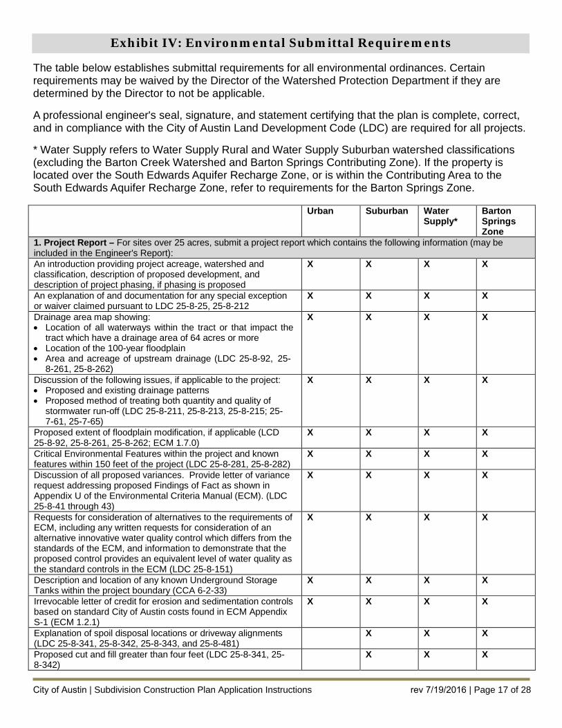
Exhibit IV: Environmental Submittal Requirements
The table below establishes submittal requirements for all environmental ordinances. Certain requirements may be waived by the Director of the Watershed Protection Department if they are determined by the Director to not be applicable.
A professional engineer's seal, signature, and statement certifying that the plan is complete, correct, and in compliance with the City of Austin Land Development Code (LDC) are required for all projects.
* Water Supply refers to Water Supply Rural and Water Supply Suburban watershed classifications(excluding the Barton Creek Watershed and Barton Springs Contributing Zone). If the property is located over the South Edwards Aquifer Recharge Zone, or is within the Contributing Area to the South Edwards Aquifer Recharge Zone, refer to requirements for the Barton Springs Zone.
Urban Suburban Water Supply*
Barton Springs Zone
1. Project Report – For sites over 25 acres, submit a project report which contains the following information (may beincluded in the Engineer's Report): An introduction providing project acreage, watershed and classification, description of proposed development, and description of project phasing, if phasing is proposed
X X X X
An explanation of and documentation for any special exception or waiver claimed pursuant to LDC 25-8-25, 25-8-212
X X X X
Drainage area map showing: • Location of all waterways within the tract or that impact the
tract which have a drainage area of 64 acres or more• Location of the 100-year floodplain• Area and acreage of upstream drainage (LDC 25-8-92, 25-
8-261, 25-8-262)
X X X X
Discussion of the following issues, if applicable to the project: • Proposed and existing drainage patterns• Proposed method of treating both quantity and quality of
stormwater run-off (LDC 25-8-211, 25-8-213, 25-8-215; 25-7-61, 25-7-65)
X X X X
Proposed extent of floodplain modification, if applicable (LCD 25-8-92, 25-8-261, 25-8-262; ECM 1.7.0)
X X X X
Critical Environmental Features within the project and known features within 150 feet of the project (LDC 25-8-281, 25-8-282)
X X X X
Discussion of all proposed variances. Provide letter of variance request addressing proposed Findings of Fact as shown in Appendix U of the Environmental Criteria Manual (ECM). (LDC 25-8-41 through 43)
X X X X
Requests for consideration of alternatives to the requirements of ECM, including any written requests for consideration of an alternative innovative water quality control which differs from the standards of the ECM, and information to demonstrate that the proposed control provides an equivalent level of water quality as the standard controls in the ECM (LDC 25-8-151)
X X X X
Description and location of any known Underground Storage Tanks within the project boundary (CCA 6-2-33)
X X X X
Irrevocable letter of credit for erosion and sedimentation controls based on standard City of Austin costs found in ECM Appendix S-1 (ECM 1.2.1)
X X X X
Explanation of spoil disposal locations or driveway alignments (LDC 25-8-341, 25-8-342, 25-8-343, and 25-8-481)
X X X
Proposed cut and fill greater than four feet (LDC 25-8-341, 25- 8-342)
X X X
City of Austin | Subdivision Construction Plan Application Instructions rev 7/19/2016 | Page 17 of 28
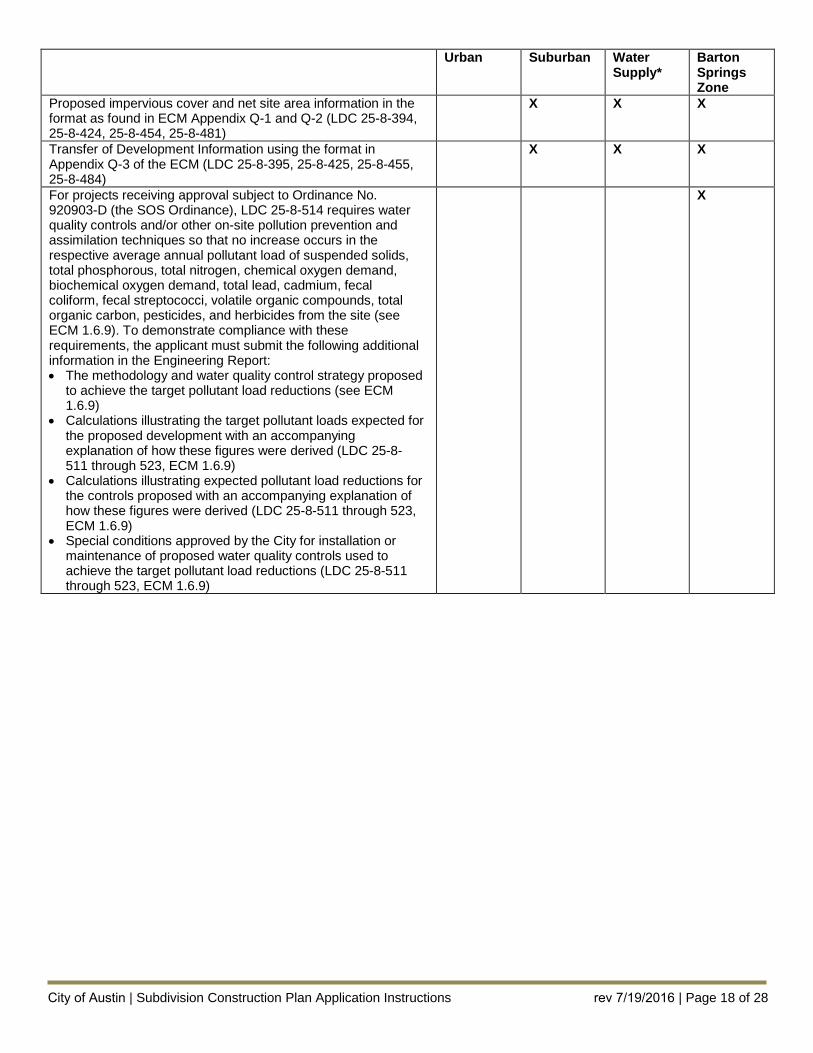
Urban Suburban Water Supply*
Barton Springs Zone
Proposed impervious cover and net site area information in the format as found in ECM Appendix Q-1 and Q-2 (LDC 25-8-394, 25-8-424, 25-8-454, 25-8-481)
X X X
Transfer of Development Information using the format in Appendix Q-3 of the ECM (LDC 25-8-395, 25-8-425, 25-8-455, 25-8-484)
X X X
For projects receiving approval subject to Ordinance No. 920903-D (the SOS Ordinance), LDC 25-8-514 requires water quality controls and/or other on-site pollution prevention and assimilation techniques so that no increase occurs in the respective average annual pollutant load of suspended solids, total phosphorous, total nitrogen, chemical oxygen demand, biochemical oxygen demand, total lead, cadmium, fecal coliform, fecal streptococci, volatile organic compounds, total organic carbon, pesticides, and herbicides from the site (see ECM 1.6.9). To demonstrate compliance with these requirements, the applicant must submit the following additional information in the Engineering Report: • The methodology and water quality control strategy proposed
to achieve the target pollutant load reductions (see ECM1.6.9)
• Calculations illustrating the target pollutant loads expected forthe proposed development with an accompanyingexplanation of how these figures were derived (LDC 25-8-511 through 523, ECM 1.6.9)
• Calculations illustrating expected pollutant load reductions forthe controls proposed with an accompanying explanation ofhow these figures were derived (LDC 25-8-511 through 523,ECM 1.6.9)
• Special conditions approved by the City for installation ormaintenance of proposed water quality controls used toachieve the target pollutant load reductions (LDC 25-8-511through 523, ECM 1.6.9)
X
City of Austin | Subdivision Construction Plan Application Instructions rev 7/19/2016 | Page 18 of 28
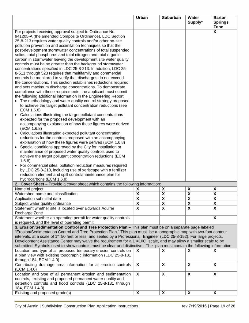
Urban Suburban Water Supply*
Barton Springs Zone
For projects receiving approval subject to Ordinance No. 941205-A (the amended Composite Ordinance), LDC Section 25-8-213 requires water quality controls and/or other on-site pollution prevention and assimilation techniques so that the post-development stormwater concentrations of total suspended solids, total phosphorus and total nitrogen and total organic carbon in stormwater leaving the development site water quality controls must be no greater than the background stormwater concentrations specified in LDC 25-8-213. In addition, LDC 25-8-511 through 523 requires that multifamily and commercial controls be monitored to verify that discharges do not exceed the concentrations. This section establishes reductions required, and sets maximum discharge concentrations. To demonstrate compliance with these requirements, the applicant must submit the following additional information in the Engineering Report: • The methodology and water quality control strategy proposed
to achieve the target pollutant concentration reductions (seeECM 1.6.8)
• Calculations illustrating the target pollutant concentrationsexpected for the proposed development with anaccompanying explanation of how these figures were derived(ECM 1.6.8)
• Calculations illustrating expected pollutant concentrationreductions for the controls proposed with an accompanyingexplanation of how these figures were derived (ECM 1.6.8)
• Special conditions approved by the City for installation ormaintenance of proposed water quality controls used toachieve the target pollutant concentration reductions (ECM1.6.8)
• For commercial sites, pollution reduction measures requiredby LDC 25-8-213, including use of xeriscape with a fertilizerreduction element and spill control/maintenance plan forhydrocarbons (ECM 1.6.8)
X
2. Cover Sheet – Provide a cover sheet which contains the following information:Name of project X X X X Watershed name and classification X X X X Application submittal date X X X X Subject water quality ordinance X X X X Statement whether site is located over Edwards Aquifer Recharge Zone
X X X X
Statement whether an operating permit for water quality controls is required, and the level of operating permit
X
3. Erosion/Sedimentation Control and Tree Protection Plan – This plan must be on a separate page labeled“Erosion/Sedimentation Control and Tree Protection Plan." This plan must be a topographic map with two-foot contour intervals, at a scale of 1"=50 feet or less, and sealed by a Professional Engineer (LDC 25-8-152). For large projects, Development Assistance Center may waive the requirement for a 1"=100' scale, and may allow a smaller scale to be submitted. Symbols used to show controls must be clear and distinctive. The plan must contain the following information: Location and type of all proposed temporary erosion controls on a plan view with existing topographic information (LDC 25-8-181 through 184, ECM 1.4.0)
X X X X
Contributing drainage area information for all erosion controls (ECM 1.4.0)
X X X X
Location and type of all permanent erosion and sedimentation controls, existing and proposed permanent water quality and detention controls and flood controls (LDC 25-8-181 through 184, ECM 1.4.0)
X X X X
Existing and proposed grade(s) X X X X
City of Austin | Subdivision Construction Plan Application Instructions rev 7/19/2016 | Page 19 of 28
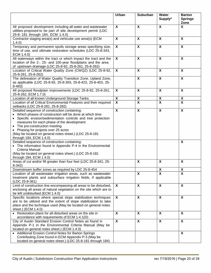
Urban Suburban Water Supply*
Barton Springs Zone
All proposed development including all water and wastewater utilities proposed to be part of site development permit (LDC 25-8- 181 through 184, ECM 1.4.0)
X X X X
Contractor staging area(s) and vehicular use area(s) (ECM 1.4.0)
X X X X
Temporary and permanent spoils storage areas specifying size, time of use, and ultimate restoration schedules (LDC 25-8-343, ECM 1.4.0)
X X X X
All waterways within the tract or which impact the tract and the location of the 2-, 25- and 100-year floodplains and the area of upstream drainage (LDC 25-8-92, 25-8-261, 25-8-262)
X X X X
Location of Critical Water Quality Zone (CWQZ) (LDC 25-8-92, 25-8-261, 25-8-262)
X X X X
The delineation of Water Quality Transition Zone, Upland Zone, as applicable (LDC 25-8-93, 25-8-393, 25-8-423, 25-8-453, 25-8-483)
X X X
All proposed floodplain improvements (LDC 25-8-92, 25-8-261, 25-8-262, ECM 1.7.0)
X X X X
Location of all known Underground Storage Tanks X X X X Location of all Critical Environmental Features and their required setbacks (LDC 25-8-281, 25-8-282)
X X X X
Detailed sequence of construction containing: • Which phases of construction will be done at which time• Specific erosion/sedimentation controls and tree protection
measures for each phase of the development• The pre-construction meeting• Phasing for projects over 25 acres(May be located on general notes sheet.) (LDC 25-8-181 through 184, ECM 1.4.0)
X X X X
Detailed sequence of construction containing: • The information found in Appendix P-4 in the Environmental
Criteria Manual(May be located on general notes sheet.) (LDC 25-8-181 through 184, ECM 1.4.0)
X
Areas of cut and/or fill greater than four feet (LDC 25-8-341, 25- 8-342)
X X X
Downstream buffer zones as required by LDC 25-8-454 X X Location of all wastewater irrigation areas, such as wastewater treatment plants and subsurface irrigation fields, if applicable (LDC 25-8-361)
X X X
Limit of construction line encompassing all areas to be disturbed, enclosing all areas of natural vegetation on the site which are to be left undisturbed (ECM 1.4.0)
X X X X
Specific locations where special slope stabilization techniques are to be utilized and the extent of slope stabilization to take place and the technique used (May be located on general notes sheet.) (ECM 1.4.0)
X X X X
• Restoration plans for all disturbed areas on the site inaccordance with requirements of ECM 1.4.1(D)
X X X X
City of Austin Standard Erosion Control Notes as found in Appendix P-1 in the Environmental Criteria Manual (May be located on general notes sheet.) (ECM 1.4.0)
X X X X
• Additional Erosion Control Notes for Barton SpringsContributing Zone found in ECM Appendix P-3 (May belocated on general notes sheet.) (LDC 25-8-181 through 184)
X
City of Austin | Subdivision Construction Plan Application Instructions rev 7/19/2016 | Page 20 of 28
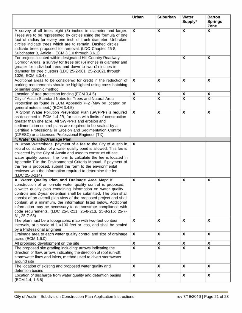
Urban Suburban Water Supply*
Barton Springs Zone
A survey of all trees eight (8) inches in diameter and larger. Trees are to be represented by circles using the formula of one foot of radius for every one inch of trunk diameter. Unbroken circles indicate trees which are to remain. Dashed circles indicate trees proposed for removal. (LDC Chapter 25-8, Subchapter B, Article I, ECM 3.1.0 through 3.6.1)
X X X X
For projects located within designated Hill Country Roadway Corridor Areas, a survey for trees six (6) inches in diameter and greater for individual trees and down to two (2) inches in diameter for tree clusters (LDC 25-2-981, 25-2-1021 through 1026, ECM 3.3.4)
X X
Additional areas to be considered for credit in the reduction of parking requirements should be highlighted using cross hatching or similar graphic method
X X X X
Location of tree protection fencing (ECM 3.4.5) X X X X City of Austin Standard Notes for Trees and Natural Area Protection as found in ECM Appendix P-2 (May be located on general notes sheet.) (ECM 3.4.5)
X X X X
A Storm Water Pollution Prevention Plan (SWPPP) is required as described in ECM 1.4.2B, for sites with limits of construction greater than one acre. All SWPPPs and erosion and sedimentation control plans are required to be sealed by a Certified Professional in Erosion and Sedimentation Control (CPESC) or a Licensed Professional Engineer (TX).
X X X X
4. Water Quality/Drainage PlanIn Urban Watersheds, payment of a fee to the City of Austin in lieu of construction of a water quality pond is allowed. This fee is collected by the City of Austin and used to construct off-site water quality ponds. The form to calculate the fee is located in Appendix T in the Environmental Criteria Manual. If payment of the fee is proposed, submit the form to the environmental reviewer with the information required to determine the fee. (LDC 25-8-214)
X
A. Water Quality Plan and Drainage Area Map: If construction of an on-site water quality control is proposed, a water quality plan containing information on water quality controls and 2-year detention shall be submitted. The plan shall consist of an overall plan view of the proposed project and shall contain, at a minimum, the information listed below. Additional information may be necessary to demonstrate compliance with code requirements. (LDC 25-8-211, 25-8-213, 25-8-215; 25-7- 61, 25-7-65)
X X X X
The plan must be a topographic map with two-foot contour intervals, at a scale of 1"=100 feet or less, and shall be sealed by a Professional Engineer
X X X X
Drainage area to each water quality control and size of drainage acres (ECM 1.6.0)
X X X X
All proposed development on the site X X X X The proposed site grading including: arrows indicating the direction of flow, arrows indicating the direction of roof run-off, stormwater lines and inlets, method used to divert stormwater around site
X X X X
The location of existing and proposed water quality and detention basins
X X X X
Location of discharge from water quality and detention basins (ECM 1.4, 1.6.5)
X X X X
City of Austin | Subdivision Construction Plan Application Instructions rev 7/19/2016 | Page 21 of 28
Urban Suburban Water Supply*
Barton Springs Zone
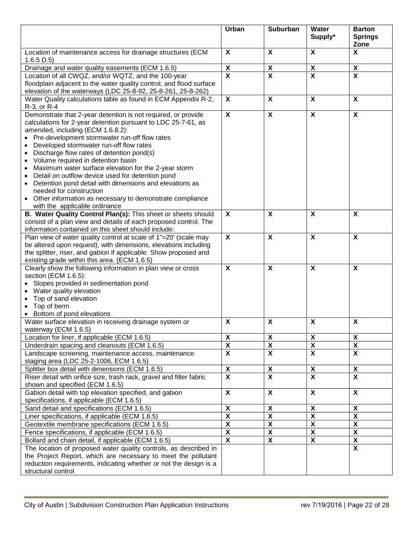
Location of maintenance access for drainage structures (ECM 1.6.5 D.5)
X X X X
Drainage and water quality easements (ECM 1.6.5) X X X X Location of all CWQZ, and/or WQTZ, and the 100-year floodplain adjacent to the water quality control, and flood surface elevation of the waterways (LDC 25-8-92, 25-8-261, 25-8-262)
X X X X
Water Quality calculations table as found in ECM Appendix R-2, R-3, or R-4
X X X X
Demonstrate that 2-year detention is not required, or provide calculations for 2-year detention pursuant to LDC 25-7-61, as amended, including (ECM 1.6.8.2): • Pre-development stormwater run-off flow rates• Developed stormwater run-off flow rates• Discharge flow rates of detention pond(s)• Volume required in detention basin• Maximum water surface elevation for the 2-year storm• Detail on outflow device used for detention pond• Detention pond detail with dimensions and elevations as
needed for construction• Other information as necessary to demonstrate compliance
with the applicable ordinance
X X X X
B. Water Quality Control Plan(s): This sheet or sheets should consist of a plan view and details of each proposed control. The information contained on this sheet should include:
X X X X
Plan view of water quality control at scale of 1"=20' (scale may be altered upon request), with dimensions, elevations including the splitter, riser, and gabion if applicable. Show proposed and existing grade within this area. (ECM 1.6.5)
X X X X
Clearly show the following information in plan view or cross section (ECM 1.6.5): • Slopes provided in sedimentation pond• Water quality elevation• Top of sand elevation• Top of berm• Bottom of pond elevations
X X X X
Water surface elevation in receiving drainage system or waterway (ECM 1.6.5)
X X X X
Location for liner, if applicable (ECM 1.6.5) X X X X Underdrain spacing and cleanouts (ECM 1.6.5) X X X X Landscape screening, maintenance access, maintenance staging area (LDC 25-2-1006, ECM 1.6.5)
X X X X
Splitter box detail with dimensions (ECM 1.6.5) X X X X Riser detail with orifice size, trash rack, gravel and filter fabric shown and specified (ECM 1.6.5)
X X X X
Gabion detail with top elevation specified, and gabion specifications, if applicable (ECM 1.6.5)
X X X X
Sand detail and specifications (ECM 1.6.5) X X X X Liner specifications, if applicable (ECM 1.6.5) X X X X Geotextile membrane specifications (ECM 1.6.5) X X X X Fence specifications, if applicable (ECM 1.6.5) X X X X Bollard and chain detail, if applicable (ECM 1.6.5) X X X X The location of proposed water quality controls, as described in the Project Report, which are necessary to meet the pollutant reduction requirements, indicating whether or not the design is a structural control
X
City of Austin | Subdivision Construction Plan Application Instructions rev 7/19/2016 | Page 22 of 28
Urban Suburban Water Supply*
Barton Springs Zone
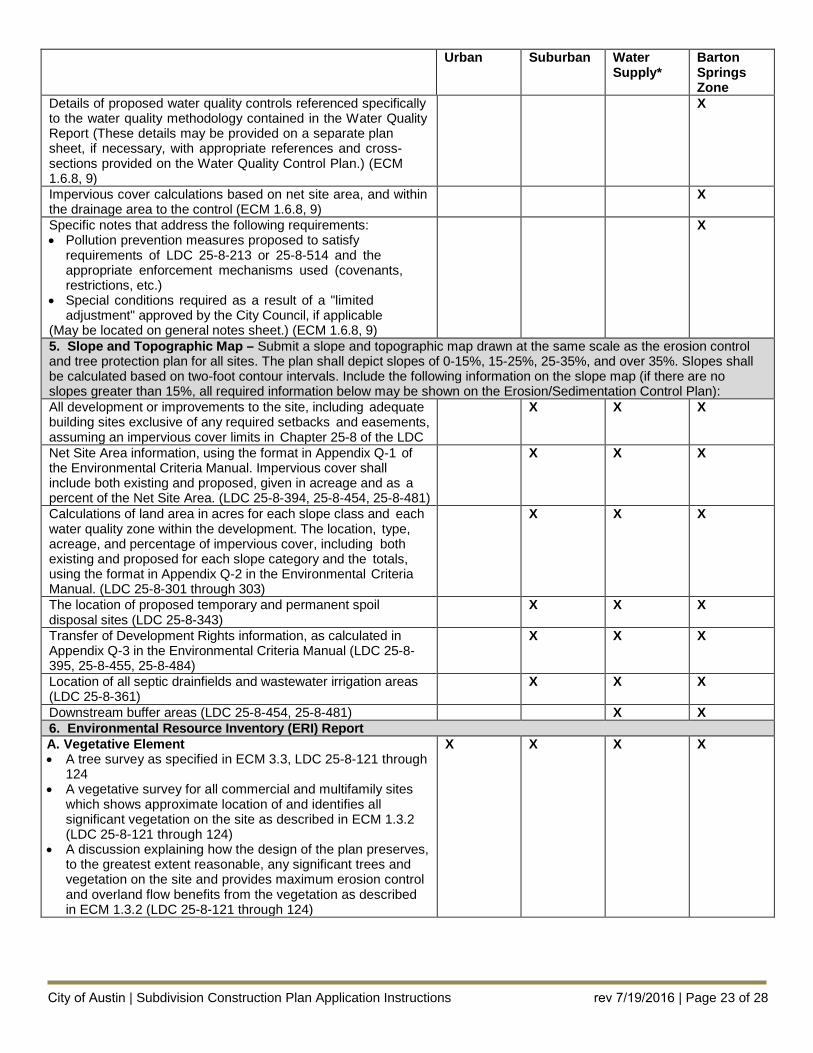
Details of proposed water quality controls referenced specifically to the water quality methodology contained in the Water Quality Report (These details may be provided on a separate plan sheet, if necessary, with appropriate references and cross- sections provided on the Water Quality Control Plan.) (ECM 1.6.8, 9)
X
Impervious cover calculations based on net site area, and within the drainage area to the control (ECM 1.6.8, 9)
X
Specific notes that address the following requirements: • Pollution prevention measures proposed to satisfy
requirements of LDC 25-8-213 or 25-8-514 and theappropriate enforcement mechanisms used (covenants,restrictions, etc.)
• Special conditions required as a result of a "limitedadjustment" approved by the City Council, if applicable
(May be located on general notes sheet.) (ECM 1.6.8, 9)
X
5. Slope and Topographic Map – Submit a slope and topographic map drawn at the same scale as the erosion controland tree protection plan for all sites. The plan shall depict slopes of 0-15%, 15-25%, 25-35%, and over 35%. Slopes shall be calculated based on two-foot contour intervals. Include the following information on the slope map (if there are no slopes greater than 15%, all required information below may be shown on the Erosion/Sedimentation Control Plan): All development or improvements to the site, including adequate building sites exclusive of any required setbacks and easements, assuming an impervious cover limits in Chapter 25-8 of the LDC
X X X
Net Site Area information, using the format in Appendix Q-1 of the Environmental Criteria Manual. Impervious cover shall include both existing and proposed, given in acreage and as a percent of the Net Site Area. (LDC 25-8-394, 25-8-454, 25-8-481)
X X X
Calculations of land area in acres for each slope class and each water quality zone within the development. The location, type, acreage, and percentage of impervious cover, including both existing and proposed for each slope category and the totals, using the format in Appendix Q-2 in the Environmental Criteria Manual. (LDC 25-8-301 through 303)
X X X
The location of proposed temporary and permanent spoil disposal sites (LDC 25-8-343)
X X X
Transfer of Development Rights information, as calculated in Appendix Q-3 in the Environmental Criteria Manual (LDC 25-8-395, 25-8-455, 25-8-484)
X X X
Location of all septic drainfields and wastewater irrigation areas (LDC 25-8-361)
X X X
Downstream buffer areas (LDC 25-8-454, 25-8-481) X X 6. Environmental Resource Inventory (ERI) ReportA. Vegetative Element • A tree survey as specified in ECM 3.3, LDC 25-8-121 through
124 • A vegetative survey for all commercial and multifamily sites
which shows approximate location of and identifies allsignificant vegetation on the site as described in ECM 1.3.2(LDC 25-8-121 through 124)
• A discussion explaining how the design of the plan preserves,to the greatest extent reasonable, any significant trees andvegetation on the site and provides maximum erosion controland overland flow benefits from the vegetation as describedin ECM 1.3.2 (LDC 25-8-121 through 124)
X X X X
City of Austin | Subdivision Construction Plan Application Instructions rev 7/19/2016 | Page 23 of 28
Urban Suburban Water Supply*
Barton Springs Zone
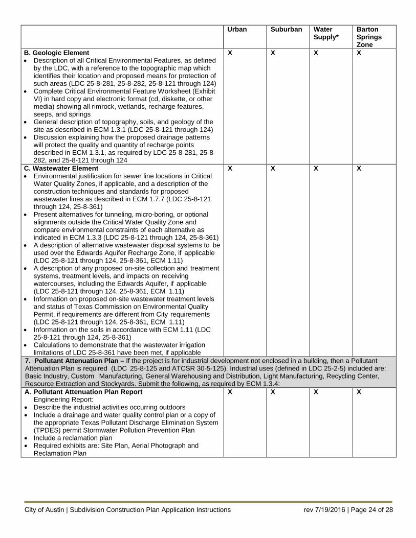
B. Geologic Element • Description of all Critical Environmental Features, as defined
by the LDC, with a reference to the topographic map whichidentifies their location and proposed means for protection ofsuch areas (LDC 25-8-281, 25-8-282, 25-8-121 through 124)
• Complete Critical Environmental Feature Worksheet (ExhibitVI) in hard copy and electronic format (cd, diskette, or othermedia) showing all rimrock, wetlands, recharge features, seeps, and springs
• General description of topography, soils, and geology of thesite as described in ECM 1.3.1 (LDC 25-8-121 through 124)
• Discussion explaining how the proposed drainage patternswill protect the quality and quantity of recharge pointsdescribed in ECM 1.3.1, as required by LDC 25-8-281, 25-8-282, and 25-8-121 through 124
X X X X
C. Wastewater Element • Environmental justification for sewer line locations in Critical
Water Quality Zones, if applicable, and a description of theconstruction techniques and standards for proposedwastewater lines as described in ECM 1.7.7 (LDC 25-8-121through 124, 25-8-361)
• Present alternatives for tunneling, micro-boring, or optionalalignments outside the Critical Water Quality Zone andcompare environmental constraints of each alternative asindicated in ECM 1.3.3 (LDC 25-8-121 through 124, 25-8-361)
• A description of alternative wastewater disposal systems to beused over the Edwards Aquifer Recharge Zone, if applicable(LDC 25-8-121 through 124, 25-8-361, ECM 1.11)
• A description of any proposed on-site collection and treatmentsystems, treatment levels, and impacts on receivingwatercourses, including the Edwards Aquifer, if applicable(LDC 25-8-121 through 124, 25-8-361, ECM 1.11)
• Information on proposed on-site wastewater treatment levelsand status of Texas Commission on Environmental QualityPermit, if requirements are different from City requirements(LDC 25-8-121 through 124, 25-8-361, ECM 1.11)
• Information on the soils in accordance with ECM 1.11 (LDC25-8-121 through 124, 25-8-361)
• Calculations to demonstrate that the wastewater irrigationlimitations of LDC 25-8-361 have been met, if applicable
X X X X
7. Pollutant Attenuation Plan – If the project is for industrial development not enclosed in a building, then a PollutantAttenuation Plan is required (LDC 25-8-125 and ATCSR 30-5-125). Industrial uses (defined in LDC 25-2-5) included are: Basic Industry, Custom Manufacturing, General Warehousing and Distribution, Light Manufacturing, Recycling Center, Resource Extraction and Stockyards. Submit the following, as required by ECM 1.3.4: A. Pollutant Attenuation Plan Report
Engineering Report: • Describe the industrial activities occurring outdoors• Include a drainage and water quality control plan or a copy of
the appropriate Texas Pollutant Discharge Elimination System(TPDES) permit Stormwater Pollution Prevention Plan
• Include a reclamation plan• Required exhibits are: Site Plan, Aerial Photograph and
Reclamation Plan
X X X X
City of Austin | Subdivision Construction Plan Application Instructions rev 7/19/2016 | Page 24 of 28
Urban Suburban Water Supply*
Barton Springs Zone
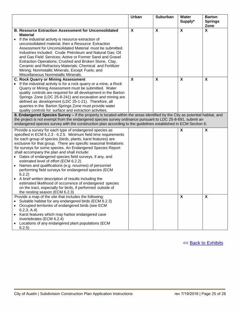
B. Resource Extraction Assessment for Unconsolidated Material
• If the industrial activity is resource extraction ofunconsolidated material, then a Resource ExtractionAssessment for Unconsolidated Material must be submitted.Industries included: Crude Petroleum and Natural Gas; Oiland Gas Field Services; Active or Former Sand and GravelExtraction Operations; Crushed and Broken Stone, Clay,Ceramic and Refractory Materials; Chemical and FertilizerMining; Nonmetallic Minerals, Except Fuels; andMiscellaneous Nonmetallic Minerals.
X X X X
C. Rock Quarry or Mining Assessment • If the industrial activity is for a rock quarry or a mine, a Rock
Quarry or Mining Assessment must be submitted. Waterquality controls are required for all development in the BartonSprings Zone (LDC 25-8-241) and excavation and mining aredefined as development (LDC 25-1-21). Therefore, allquarries in the Barton Springs Zone must provide waterquality controls for surface and extraction activities.
X X X X
8. Endangered Species Survey – If the property is located within the areas identified by the City as potential habitat, andthe project is not exempt from the endangered species survey ordinance pursuant to LDC 25-8-691, submit an endangered species survey with the construction plan according to the guidelines established in ECM Section 6: Provide a survey for each type of endangered species as specified in ECM 6.2.3 - 6.2.5. Minimum field time requirements for each group of species (birds, plants, karst features) are exclusive for that group. There are specific seasonal limitations for surveys for some species. An Endangered Species Report shall accompany the plan and shall include: • Dates of endangered species field surveys, if any, and
estimated level of effort (ECM 6.2.2)• Names and qualifications (e.g. resumes) of personnel
performing field surveys for endangered species (ECM6.2.2)
• A brief written description of results including theestimated likelihood of occurrence of endangered specieson the tract, especially for birds, if performed outside ofthe nesting season (ECM 6.2.3)
X X
Provide a map of the site that includes the following: • Suitable habitat for any endangered birds (ECM 6.2.3)• Occupied territories of endangered birds (see ECM
6.2.3, A.4)• Karst features which may harbor endangered cave
invertebrates (ECM 6.2.4)• Locations of any endangered plant populations (ECM
6.2.5)
X X
<< Back to Exhibits
City of Austin | Subdivision Construction Plan Application Instructions rev 7/19/2016 | Page 25 of 28
City of Austin | Subdivision Construction Plan Application Instructions rev 7/19/2016 | Page 26 of 28
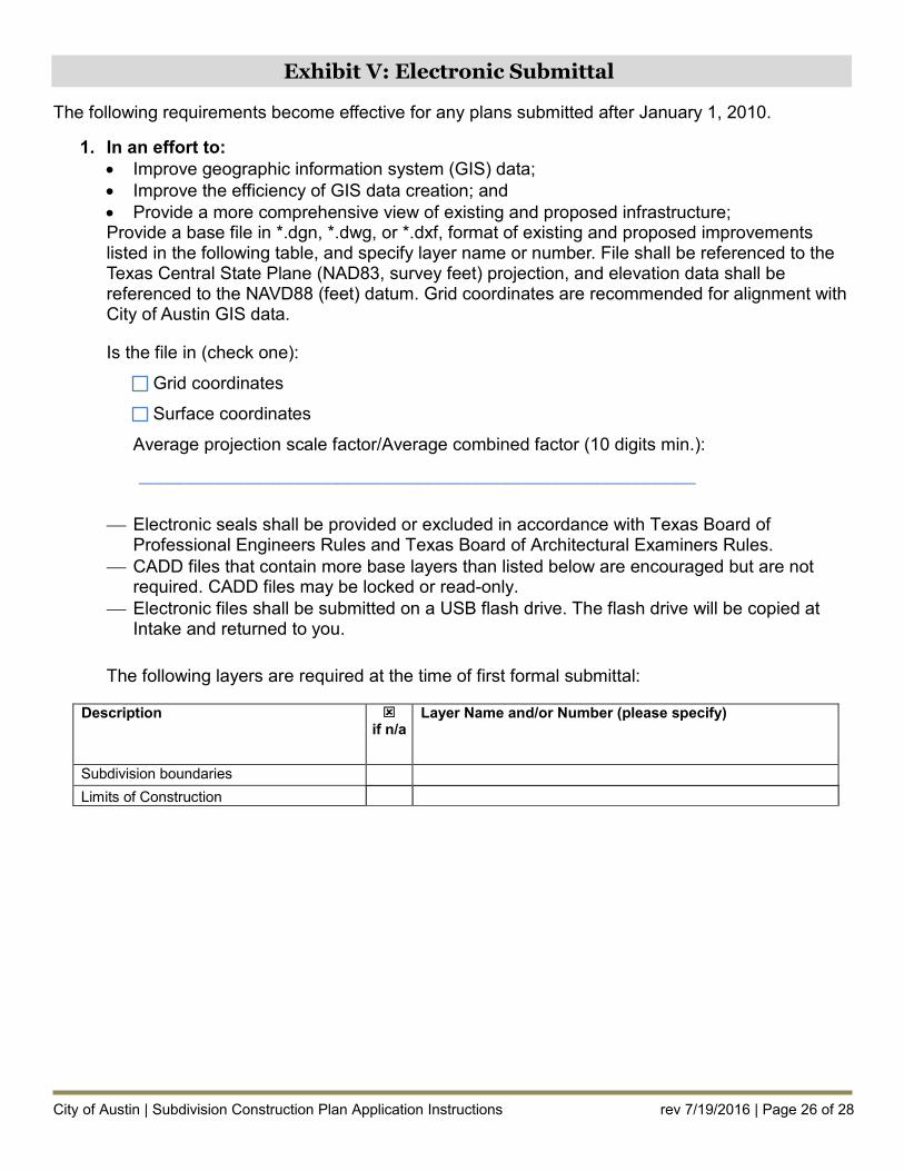
Exhibit V: Electronic Submittal
The following requirements become effective for any plans submitted after January 1, 2010.
1. In an effort to:• Improve geographic information system (GIS) data;• Improve the efficiency of GIS data creation; and• Provide a more comprehensive view of existing and proposed infrastructure;Provide a base file in *.dgn, *.dwg, or *.dxf, format of existing and proposed improvements listed in the following table, and specify layer name or number. File shall be referenced to the Texas Central State Plane (NAD83, survey feet) projection, and elevation data shall be referenced to the NAVD88 (feet) datum. Grid coordinates are recommended for alignment with City of Austin GIS data.
Is the file in (check one):
Grid coordinates
Surface coordinates
Average projection scale factor/Average combined factor (10 digits min.):
________________________________________________________
Electronic seals shall be provided or excluded in accordance with Texas Board of Professional Engineers Rules and Texas Board of Architectural Examiners Rules.
CADD files that contain more base layers than listed below are encouraged but are not required. CADD files may be locked or read-only.
Electronic files shall be submitted on a USB flash drive. The flash drive will be copied at Intake and returned to you.
The following layers are required at the time of first formal submittal:
Description if n/a
Layer Name and/or Number (please specify)
Subdivision boundaries Limits of Construction
City of Austin | Subdivision Construction Plan Application Instructions rev 7/19/2016 | Page 27 of 28
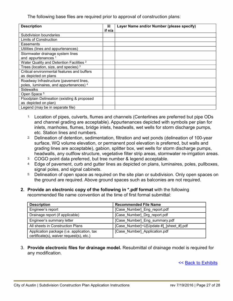
The following base files are required prior to approval of construction plans:
Description if n/a
Layer Name and/or Number (please specify)
Subdivision boundaries Limits of Construction Easements Utilities (lines and appurtenances) Stormwater drainage system lines and appurtenances 1
Water Quality and Detention Facilities 2
Trees (location, size, and species) 3
Critical environmental features and buffers as depicted on plans Roadway Infrastructure (pavement lines, poles, luminaires, and appurtenances) 4 Sidewalks Open Space 5Floodplain Delineation (existing & proposed as depicted on plan) Legend (may be in separate file)
1: Location of pipes, culverts, flumes and channels (Centerlines are preferred but pipe ODs and channel grading are acceptable). Appurtenances depicted with symbols per plan for inlets, manholes, flumes, bridge inlets, headwalls, wet wells for storm discharge pumps, etc. Station lines and numbers.
2: Delineation of detention, sedimentation, filtration and wet ponds (delineation of 100-year surface, WQ volume elevation, or permanent pool elevation is preferred, but walls and grading lines are acceptable), gabion, splitter box, wet wells for storm discharge pumps, headwalls, any outflow structure, vegetative filter strip areas, stormwater re-irrigation areas.
3: COGO point data preferred, but tree number & legend acceptable. 4: Edge of pavement, curb and gutter lines as depicted on plans, luminaires, poles, pullboxes,
signal poles, and signal cabinets. 5: Delineation of open space as required on the site plan or subdivision. Only open spaces on
the ground are required. Above ground spaces such as balconies are not required.
2. Provide an electronic copy of the following in *.pdf format with the followingrecommended file name convention at the time of first formal submittal:
Description Recommended File Name Engineer’s report [Case_Number]_Eng_report.pdf Drainage report (if applicable) [Case_Number]_Drg_report.pdf Engineer’s summary letter [Case_Number]_Eng_summary.pdf All sheets in Construction Plans [Case_Number]~U[Update #]_[sheet_#].pdf Application package (i.e. application, tax certificate(s), waiver request(s), etc.)
[Case_Number]_Application.pdf
3. Provide electronic files for drainage model. Resubmittal of drainage model is required forany modification.
<< Back to Exhibits
City of Austin | Subdivision Construction Plan Application Instructions rev 7/19/2016 | Page 28 of 28
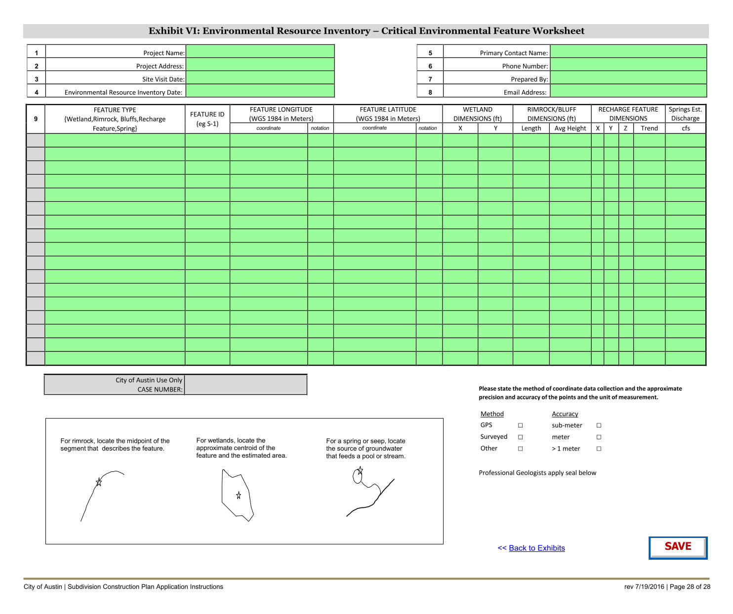
Exhibit VI: Environmental Resource Inventory – Critical Environmental Feature Worksheet
1 Project Name:
2 Project Address:
3 Site Visit Date:
4 Environmental Resource Inventory Date:
5 Primary Contact Name:
6 Phone Number:
7 Prepared By:
8 Email Address:
9 FEATURE TYPE
{Wetland,Rimrock, Bluffs,Recharge Feature,Spring}
FEATURE ID (eg S-1)
FEATURE LONGITUDE (WGS 1984 in Meters)
coordinate notation
FEATURE LATITUDE (WGS 1984 in Meters)
coordinate notation
WETLAND DIMENSIONS (ft)
X Y
RIMROCK/BLUFF DIMENSIONS (ft)
Length Avg Height
RECHARGE FEATURE DIMENSIONS
X Y Z Trend
Springs Est. Discharge
cfs
□ □ □ □ □ □
City of Austin Use Only CASE NUMBER:
For rimrock, locate the midpoint of the segment that describes the feature.
For wetlands, locate the approximate centroid of the feature and the estimated area.
For a spring or seep, locate the source of groundwater that feeds a pool or stream.
Please state the method of coordinate data collection and the approximate precision and accuracy of the points and the unit of measurement.
Method GPS
Surveyed
Other
Accuracy sub-meter
meter
> 1 meter
Professional Geologists apply seal below
<< Back to Exhibits