studying a buckling behavior for edge cracked plates...
TRANSCRIPT
Eng. & Tech. Journal,Vol.30, No.1, 2012
24
Studying a Buckling Behavior for Edge Cracked Plates Under Compression
Dr.Nathera Abdual Hassan Saleh Mechanical Department, Engineering College, University of Basrah/Basra Email: Nathera 1971 @ yahoo.com Saddam Kallsan Kuess Mechanical Department, Engineering College, University of Basrah/Basra
Received on: 7/7/2011 & Accepted on: 3/11/2011
ABSTRACT
In this work, the buckling behavior for edge cracked plates under compression loading is studied considering the influence of the crack parameters (i.e. size, location and orientation), plate aspect ratio and plate boundary conditions. The problem was solved numerically using finite element method utilizing ANSYS software version11 .The obtained results show that the crack parameters as well as plate aspect ratio and plate boundary conditions are efficient factors on the buckling coefficient and corresponding nodal patterns of such plates. The useful numerical results for buckling coefficients and corresponding nodal patterns are displayed in figures. According to the author's knowledge about the published literature on the buckling field, there is no specific report on the nodal patterns results of such edge cracked plates.
Keywords: buckling, edge crack, compression, finite element method
سلوك االنبعاج لصفائح تحتوي على شق جانبي تحت االنضغاط دراسة الخالصة
في هذا البحث تم دراسة سـلوك االنبعـاج لصـفائح تحتـوي علـى شـق جـانبي تحـت حمـل نسـبة , ) الموقـع و المـيالن , الطـول (االنضغاط باألخذ بنظر االعتبـار تـأثير محـددات الشـق
طريقـة باسـتخدام تـم حـل هـذه المسـألة عـددياً .يحةلصـف لطول الى العرض و الشروط الحدية ات االنتـائج المستحصـلة أوضـحت بـأن كـل مـن محـدد ). ANSYSبرنـامج (العناصر المحددة
العرض و الشروط الحديـة للصـفيحة عوامـل مـؤثرة علـى معامـل إلىالشق و كذلك نسبة الطول لمعامـل االنبعـاج و أشـكال الـنمط النتـائج العدديـة المفيـدة . االنبعاج و أشكال النمط المصاحبة له
بحـوث المنشـورة فـي مجـال للحسـب معرفـة البـاحثين .اًأشكال تخطيطيالمصاحبة له رسمت ب .لمثل هذه الصفائح المتشققة عند الجانب تقرير خاص بأشكال النمط وجدياالنبعاج ال
INTRODUCTION
lates of various shapes are used in architectural structures, bridges, hydraulic structures, airplanes, ships, etc, which are often subjected to normal compression, shearing and tensile loads under certain conditions,
such loads can be caused plate buckling. Buckling or elastic instability of plates P
PDF created with pdfFactory Pro trial version www.pdffactory.com
Eng. & Tech. Journal, Vol.30, No.1, 2012 Studying a Buckling Behavior for Edge Cracked Plates Under Compression
25
is of great practical importance. The buckling load depends on the plate thickness. When the plate is very thin the buckling load is very small. In many cases, a failure of thin plate elements may be attributed to an elastic instability and not to the lack of their strength. The behavior of plates are affected by the presence of defects such as cracks due to corrosion, chemical attack, fatigue, impact and imperfections.
Buckling of cracked plates has gained extensive attention by researchers. A number of studies have been reported on the buckling phenomena of cracked plates under tensile loads [1–4]. Kumar et al. [5, 6] investigated plates behavior with various types of cracks, such as edge crack and central crack under different types of loading. They calculated buckling loads using hierarchical trigonometric functions [5], as well as experimentally and numerically (i.e. finite element method) estimated ultimate strength [6] of these plates. The finite element method is used to study the buckling behavior [7-12]. Alinia et al. [7-8] studied the buckling behavior of panels with crack lie either at central or edge regions of panels under shear load. They investigated the influence of several geometrical and mechanical characteristics of cracked panels [7]. Also, they concluded that the mesh density at the crack tip plays a dominant role in the accuracy analysis in an exceptional manner but the region around the crack sides may have mesh refinements similar to uncracked panels [8]. Raviprakash et al [9] estimated the buckling strength of a thin square plate with various cracks for different crack length and orientations under axial compression load. Brighenti [10-12] studied the buckling behavior of variously cracked rectangular plates under tension and compression by considering the influence of varying some plates parameters such as relative crack length, crack orientation and Poisson’s coefficient of the plate’s material on the buckling behavior. He used the approximate theoretical procedure additional to finite element method to estimate the critical load for cracked tensioned plates[10]. Furthermore he took into account contact crack faces and friction [11]. Moreover, in his last study [12], the fracture and plastic failure have been investigated for tensioned cracked plates by varying boundary conditions. Recently, Khedmati et al. [13] presented a finite element study on the buckling strength of a cracked plate subjected to an axial compressive load. The effects of crack location(i,e. considered only for internal cracks), crack orientation, crack length and plate aspect ratio are analyzed. They concluded that the size of the crack as well as its location and orientation have significant effects on the buckling behavior of the plate.
From above review most of these studies were performed on the plates with either central or edge crack with varying crack length or orientation based on finite element method, few studies have been investigated effect of crack location on buckling behavior such as Khedmati et al. [13] take a crack at the middle of plate and moved it in one direction from one edge to the center of plate with different crack length and orientation. Crack in a plate element may be generally observed at any length, location and orientation. So, in the present
PDF created with pdfFactory Pro trial version www.pdffactory.com
Eng. & Tech. Journal, Vol.30, No.1, 2012 Studying a Buckling Behavior for Edge Cracked Plates Under Compression
26
work the buckling analysis of edge cracked thin plate under compression load characterized by different boundary conditions, crack length, location, orientation and plate aspect ratio is considered. Firstly, to determine the buckling coefficient and secondly, to display nodal patterns of first buckling mode for suck edge cracked plates using the finite element method (ANSYS Package).
THEORY
The governing differential equation of the linear buckling analysis of plates is given by [14]: + 2 + = 1 + 2 + … (1)
Where , and are the internal forces acting in the middle surface of the plate
due to the applied in-plane loading. The equilibrium equation of a rectangular plate subjected to uniform compressive force N
x per unit length in the x-direction only (i.e. = 0, =0) as shown in figure(1) can be written as + 2 + = 1 − … . (2)
where, denotes the deflection in the z-direction of any point (x ,y). After satisfying the simply supported boundary conditions, the critical buckling load (Nx
)cr can be expressed in terms of the number of half sine waves (i.e. m and n) in the buckled mode as: ( ) = ( + ⁄⁄ ) ⁄ = + … . (3)
The lowest value of the buckling load ( ) , in Eq. (3) is obtained for n=1 and can also be written as follows, ( ) = + 1 … . (4 )
Where a : Length of the plate b : Width of the plate D = Et3/12 (1- ν2) : flexural rigidity of the plate E : Young’s modulus of the plate material t : Thickness of the plate v : Poisson’s ratio Or, in an equivalent form, ( ) = … … (4 )
PDF created with pdfFactory Pro trial version www.pdffactory.com
Eng. & Tech. Journal, Vol.30, No.1, 2012 Studying a Buckling Behavior for Edge Cracked Plates Under Compression
27
Where or generally is the buckling coefficient and given by the following equation for a simply supported uncracked plate. = = + 1 … . . (5) For a given value of , the buckling coefficient depends only on the ratio a/b, called the aspect ratio of the plate. As follows from equations (4) and(5), the smallest value of , and consequently, the value of the critical force( ) , depends on the number of half-sine waves in the longitudinal direction, m. For a given aspect ratio the critical load is obtained by selecting m so that it makes equation. (4b) minimum. Since only depends on m, we have the following: = 2 + − … . (6) Since the first factor in parentheses of the above equation is nonzero, therefore we obtain = . . … (7) This provides the following minimum values of the critical load: ( ) = 4 … . . (8) The corresponding value of the buckling load parameter is = 4. The corresponding critical stress is found to be = = ( ) = = 4 (9) The variation of the buckling coefficient as a function of the aspect ratio a/b can be found in Ref. [14] for more details
For cracked plate, the bases for a series of eigen value buckling analysis on cracked plates are firstly described and later the relevant values of are determined in each case. For such cases, the following equation can be considered in order to determine the buckling strength [13]: = … . . (10) FINITE ELEMENT MODEL Model description
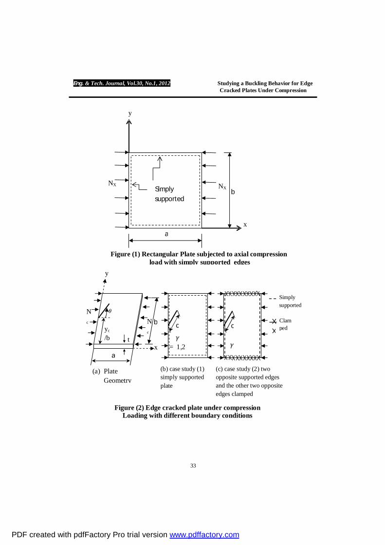
The considered cracked plate have a length a is set to be 1m, the width b is equal to 1m or 2m and the thickness t is equal to 10mm. Edge crack is assumed to be exist in the one edge of the plate, characterized by the length c and the orientation (measured anticlockwise) as shown in figure (2). There are many parameters involved in modeling and analysis of the problem that studied in this paper. These parameters including relative crack length ( / ), has been assumed to be equal (0.1, 0.2, 0.3, 0.4 0.5),relative crack locations ( )⁄ = 0.1, 0.2, 0.3, 0.4 0.5,crackorientations
PDF created with pdfFactory Pro trial version www.pdffactory.com
Eng. & Tech. Journal, Vol.30, No.1, 2012 Studying a Buckling Behavior for Edge Cracked Plates Under Compression
28
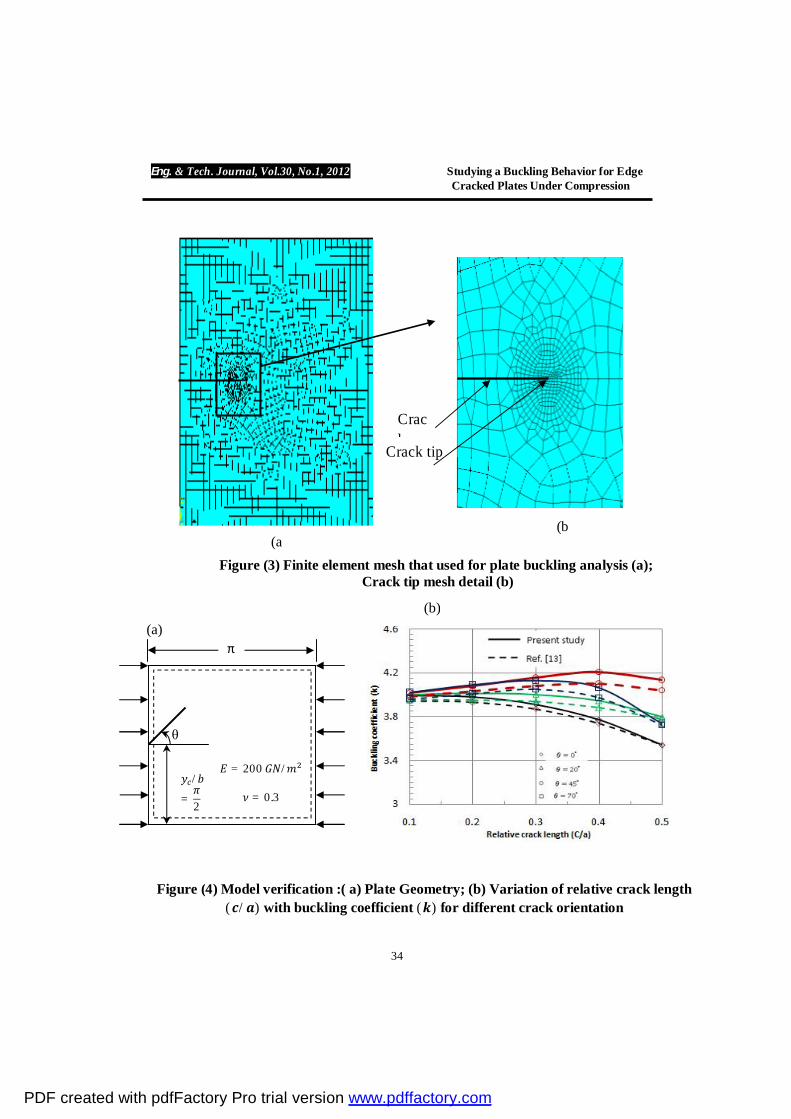
= 0°, 15°, 30°, 45°, 60° 75°, and plate aspect ratio ( = = 1 2)⁄ . Two types of boundary conditions have been considered for plate, figure (2): (i) all plate’s edges simply supported for ( = 1 2) , (ii) two opposite edges supported and the other two opposite edges clamped for ( = 1). The considered plate’s material is supposed to be linear and isotropic with Young’s modulus = 200 and Poisson’s ratio = 0.3. The finite element method (Ansys Software version11) was utilized for the modeling and buckling analysis of the cracked plates. The "shell93" element of ANSYS was used for meshing procedure. This element is suitable for analysis thin-walled structures. It is a eight-node element with six degree of freedom at each node: translations in the nodal x, y, and z directions and rotations about the x, y, and z-axes. The element has plasticity, stress stiffening, large deflection, and large strain capabilities. The adopted finite element mesh is displayed in figure (3) where the element refinement around the crack tip has been used but the region around crack sides may have mesh similar to uncracked plate. Previous studies show that the first row of the elements around a crack tip should have a radius of not greater than /8 in order to achieve accurate results. The element size is set to the upper limit of /8 in this study. More details can be found in Ref.[8, 13]. Model Verification
The reliability of the model for buckling analysis must be verified before applying it in the study. To check the accuracy of the present study, one of the cases represented by Khedmati et al [13] is selected, figure (4). In such a case an edge crack is assumed to be located in the middle of a square plate of various relative crack length and crack orientation. Figure (4b) shows the effect of the relative crack length ( / = 0.1, 0.2, 0.3, 0.4, 0.5) and crack orientation ( = 0°, 20°, 45°, 70°) on the buckling coefficient. It is seen from this figure, the present study results are in good agreements with Khedmati et al [13], of difference less than 2.5% .
RESULTS AND DISCUSSIONS
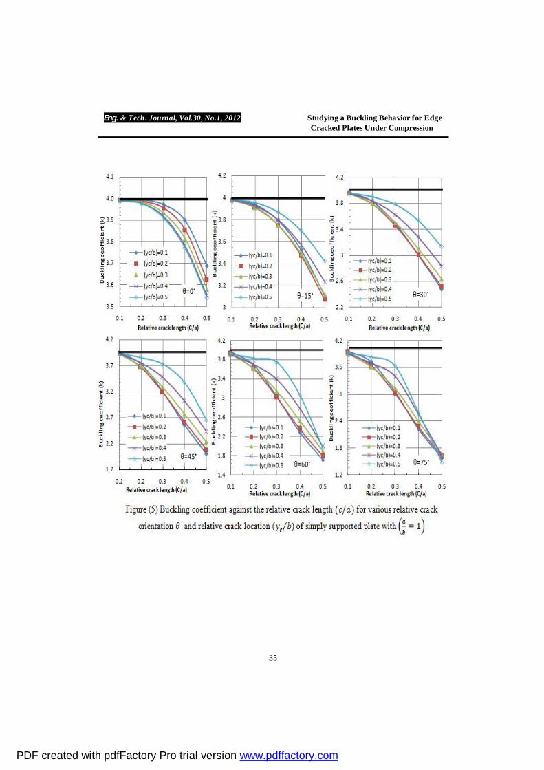
Figures (5-10) display the variation of buckling coefficient against the relative crack length ( ⁄ ) = 0.1, 0.2, 0.3, 0.4 0.5 for different relative crack locations ( )⁄ = 0.1, 0.2, 0.3, 0.4 0.5, and crack orientations = 0°, 15°, 30°, 45°, 60° 75°. Horizontal solid line in these figures corresponds to the buckling coefficient of the uncracked plate. In general from these figures, it can be noticed that the small crack 0.1 ≤ <⁄ 0.2 has little influence on the buckling coefficients in various crack locations and orientations. But , when relative crack length increases, the buckling coefficients have been effected significantly. In the following sections, each case study has been discussed separately to show the effect of the plate aspect ratio and the edges support type besides of crack parameters (i.e. length, location and orientation) on buckling coefficient.
PDF created with pdfFactory Pro trial version www.pdffactory.com

Eng. & Tech. Journal, Vol.30, No.1, 2012 Studying a Buckling Behavior for Edge Cracked Plates Under Compression
29
Case study (1) simply supported edge cracked plate. Square plate = .
As can be seen from figure (5), at the crack orientation equal zero and at any crack location, the buckling coefficient decreases with increase of the relative crack length as the crack far from the lower supported edge of the plate and approaching to the plate centre, because of any increase in the size of such crack would lead to a greater length of tearing of the plate from its edge towards its centre in the longitudinal direction since the load is parallel to the crack faces. That is why, the plate depth is practically divided into two parts and as a result its buckling resistance is diminished [13].Thus, the value of the buckling coefficient decreased to = 3.54 at crack orientation = 0° of relative crack length( ⁄ = 0.5) and crack location ( = 0.5⁄ ). While with changing the crack orientation from 15° to 75° as the crack approaching to the plate centre buckling coefficient has an opposite behavior of crack orientation = 0°. But, at = 15° the buckling coefficient at location ( = 0.1⁄ ) is greater than that at crack location ( = 0.2⁄ ) or ( = 0.3⁄ ) because of small crack orientation. Thus the smallest value of buckling coefficient equal to 3.425, 3.132, 2.653, 1.977 1.481 at crack orientation of = 15°, 30°, 45°, 60° 75° respectively of relative crack length ( ⁄ =0.5) and crack location ( = 0.5⁄ ) .
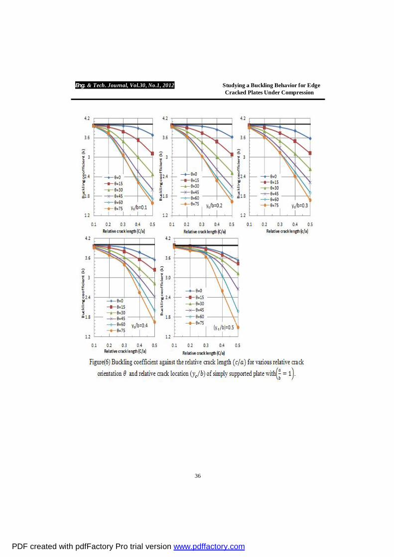
Figure (6) shows the obtained results from another viewpoint. From the observation of this figure it can be deduced that for every relative crack location the buckling coefficient decreases with the increase of the crack orientations (i.e. = 0° 75°) and relative crack length since any increase in the size and orientations of such cracks causes marked decrease in both effective length and depth of the plate, and as a combined effect, the buckling strength of the plate is decreased. It can be observed from this case study the minimum value of buckling coefficient occurs at orientation = 75° of relative crack length ( = 0.5⁄ ) and crack relative crack location ( ⁄ = 0.5) of = 1.481, so it can be considered as the dangerous one compared with uncracked plate. Since, the plate at this crack configuration is very near to the split into two parts. Rectangular plate =
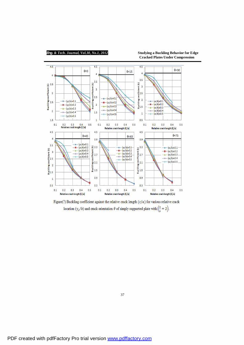
To illustrate the effect of the plate aspect ratio ( ) with crack presence on the buckling coefficient, another case has been considered with ( = 2). From figure (7) it is evident that as the crack approaching to the middle of plate (i.e. increasing relative crack location from 0.1 0.5) for every crack orientations the buckling coefficient increases. Further, it can be seen that when = 0,° the effect of the crack location appears clearly at ( > 0.3⁄ ). Almost same behavior are observed when increasing crack orientation from 15° 75° , the crack location has less effect on buckling coefficient of rectangular plate than the square plate. In rectangular plate cannot study all the cases and especially at orientations = 30°, 45°, 60° 75° because of the relative crack length not
PDF created with pdfFactory Pro trial version www.pdffactory.com
Eng. & Tech. Journal, Vol.30, No.1, 2012 Studying a Buckling Behavior for Edge Cracked Plates Under Compression
30
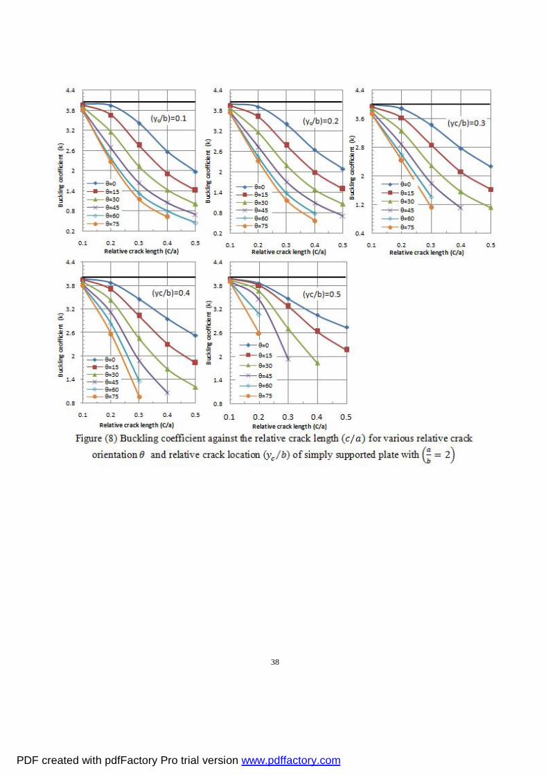
within the boundaries of the plate. It is interesting to note that the smallest value of buckling coefficient occurs when the relative crack length ( ⁄ = 0.5) and relative crack location ( ⁄ = 0.1),of = 1.979 , 1.414 , 1.007 0.451 at crack orientation = 0°, 15°, 30° 60° respectively. While, = 0.697 at crack orientation = 45° of relative crack length ⁄ = 0.5 and crack location ( ⁄ = 0.2) as well as = 0.621 at crack orientation = 75° of relative crack length ⁄ = 0.4 and crack location( ⁄ = 0.1). Figure (8) confirm that for every relative crack locations with increasing crack
orientation, it can be seen the same behavior, buckling coefficients are always decreasing. Moreover the rate of decrease of the buckling coefficient gets smaller than the square plate. It can be observed from this case study that the minimum value of buckling coefficient occurs at orientation = 60° of relative crack length ( ⁄ = 0.5) and relative crack location ( = 0.1⁄ ) of =0.451 this value is less than of value of square plate. Consequently, it can be considered more dangerous than the square plate. Case study (2) square plate with two supported edges and the other two opposite edges clamped.
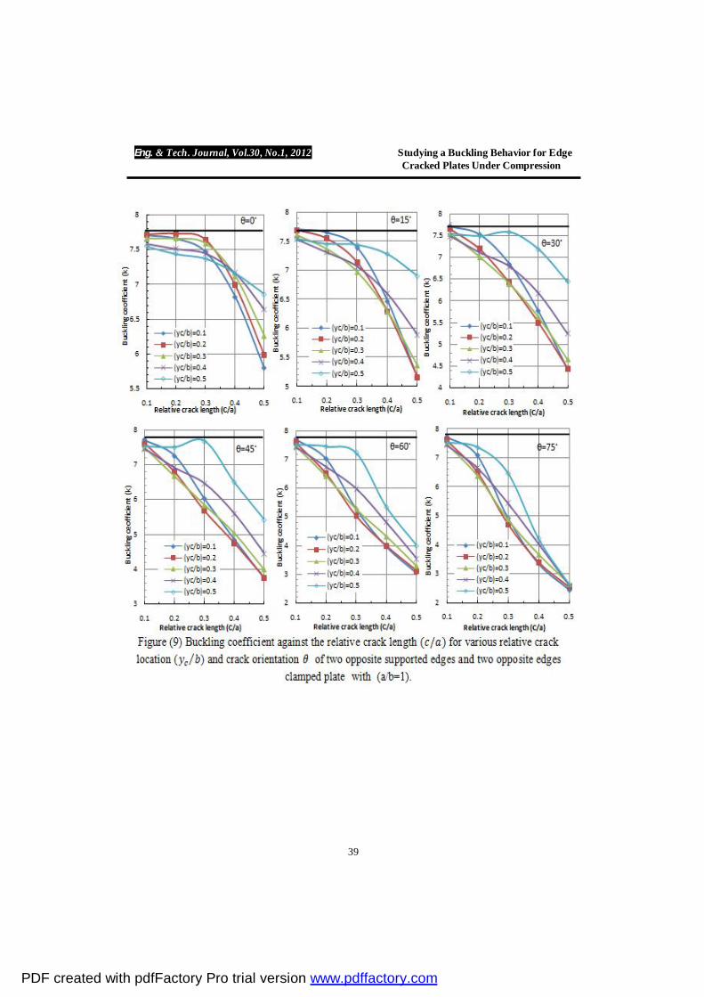
The second application studied is that square plate with two supported edges and the other two opposite edges clamped square plate, in order to study the effect of edge support type on the buckling coefficient with crack presence. The obtained results are displayed in figures (9) and (10). It is observed that the buckling behavior in this case has some differences than simply supported cases especially with crack parameters of relative crack length 0.2 < ⁄ < 0.4 and crack location ( ⁄ = 0.1, 0.2 0.3). As can be seen from figure (9), intersection points between the curves have been occurred with that crack parameters. So, it can be considered as an intermediate behavior of that case. But, in general the buckling coefficients increase as the crack approaching plate centre and decreases with rising crack orientation. Hence, the smallest value of buckling coefficient = 5.796 , 5.152 , 4.437, 3.735 , 3.042 2.445at crack orientation = 0°, 15°, 30° 45°, 60° 75° respectively of relative crack length ( ⁄ = 0.5) and relative crack location ( ⁄ = 0.1).
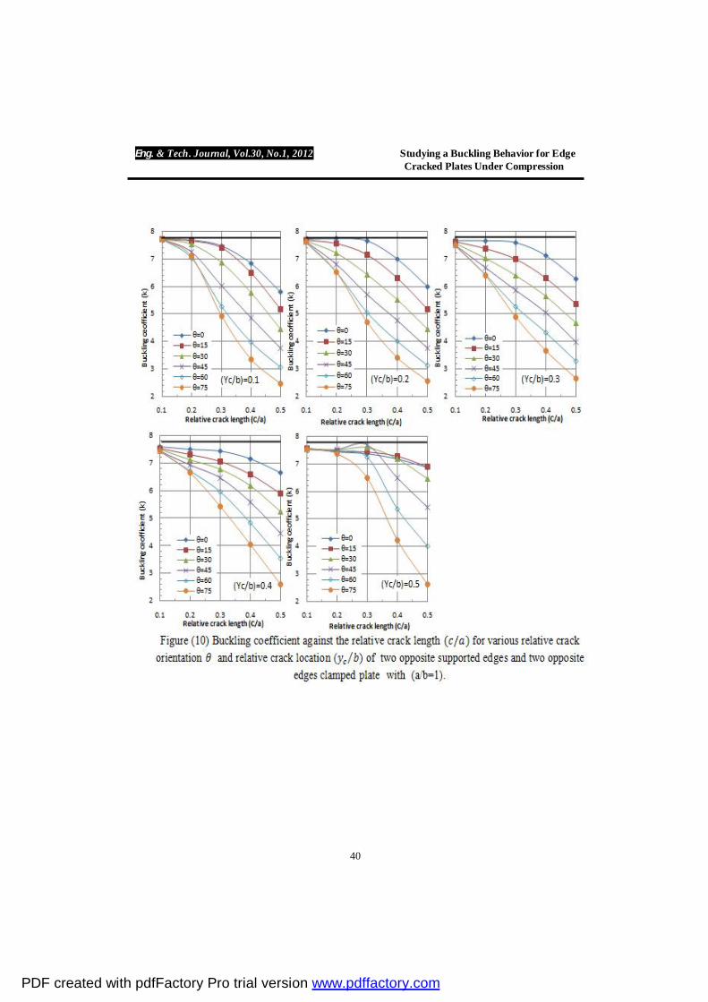
As can be seen from figure (10) the same behavior is observed for relative crack locations ( ⁄ = 0.1, 0.2, 0.3, 0.4) with increasing crack orientation, the buckling coefficient is always decreasing and the degradation of the buckling coefficient is magnified with the increase relative crack length. While at the relative crack location ( ⁄ = 0.5) there is slight changing in the buckling coefficient with crack orientation = 0° 15°. Also, at crack orientation = 30° 45° the buckling coefficient firstly increases slightly and then decreases. While, at crack orientation = 60° 75° the buckling coefficient is always decreased. It can be observed from this case study the minimum value of buckling coefficient occurs at crack orientation = 75° of relative crack length ( ⁄ = 0.5) and relative crack location ( = 0.1⁄ ) of = 2.445. It is useful to note that the maximum reduction in the buckling coefficient is
PDF created with pdfFactory Pro trial version www.pdffactory.com
Eng. & Tech. Journal, Vol.30, No.1, 2012 Studying a Buckling Behavior for Edge Cracked Plates Under Compression
31
0.682% but the maximum reduction equal to 0.629% for simply supported square plate, so it can be considered more dangerous than the simply supported square cracked plate.
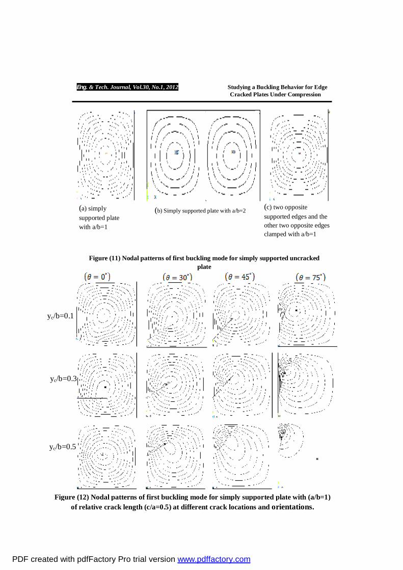
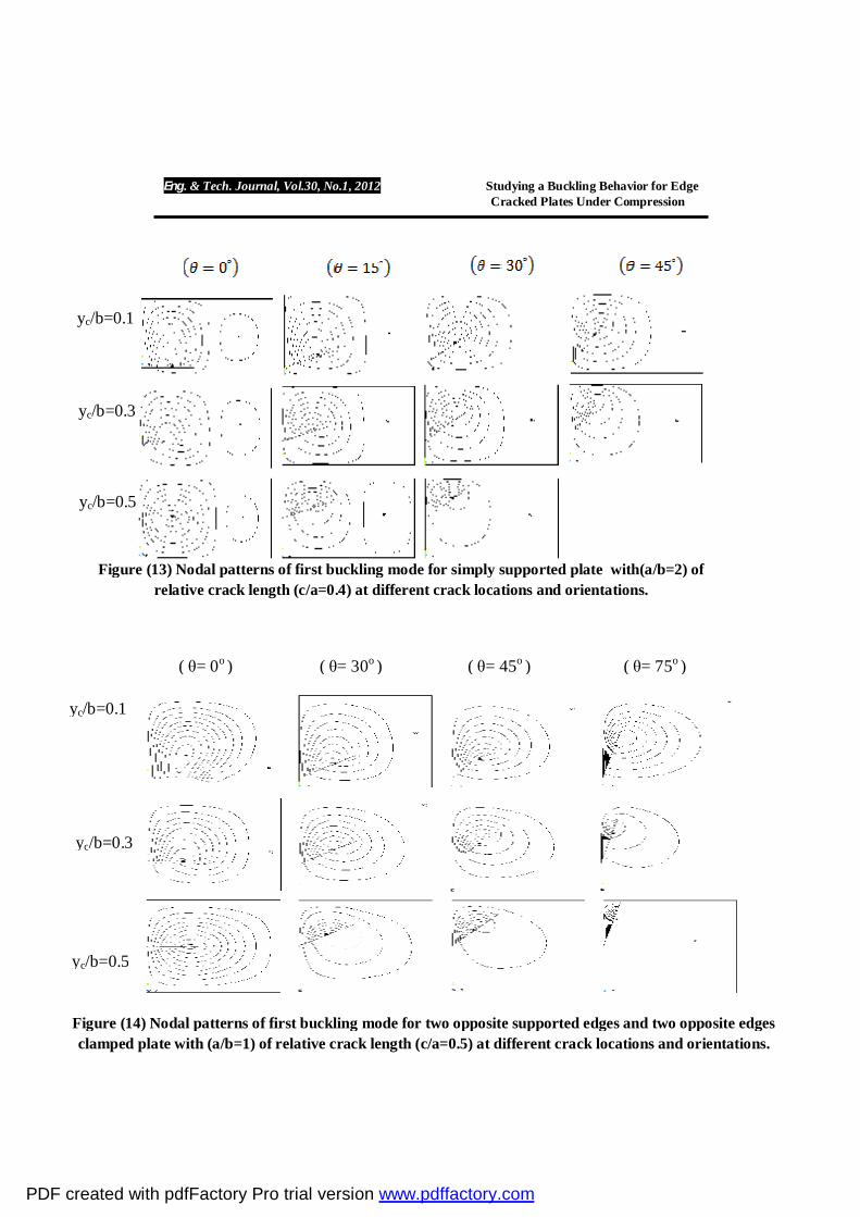
Finally, the decrease or the increase in the buckling coefficient of the above case studies can be explained by the deformed shapes of the nodal patterns, as shown in figures (12-14). From which one can observe how the crack changes the nodal patterns of the plates compared with uncracked one, figure (11).
Figures (12-14) show the nodal patterns of the first buckling mode which are extracted from the bulk analysis results, only for cracked plates characterized by ( ⁄ = 0.5), ( = 0.1, 0.3 0.5⁄ ) at different crack orientations. Since similar results (i.e. similar behavior) were obtained for cracked plates having another crack parameters for brevity. It is revealed from figure (11) that for uncracked plates , the nodal patterns are uniform and regular also for simply supported uncracked rectangular plate there are two symmetry regions. While, for cracked plates it can be shown that the nodal patterns are sensitive to the length, location and orientation of crack. Thus, the nodal patterns are no more uniform and regular as well as the crack destroys the symmetry and in some cases there is only one region of the nodal patterns for the cracked simply supported rectangular plate. According to the author's knowledge and the literature review on the buckling field of cracked plates, there is no specific report on the nodal patterns results of such cracked plates. CONCLUSIONS
In the present work, the buckling behavior of the edge cracked thin plate has been considered. The effect of some parameters such as relative crack length, relative crack location, crack orientation, boundary conditions and plate aspect ratio on the buckling coefficient of compressed cracked plates have been investigated numerically using Finite Element Method (ANSYS Package). It is shown from the computed results that:
1. Short cracks produce a little influence on the buckling coefficient and long cracks increase the influence on the buckling coefficient.
2. The buckling coefficient very sensitive to the crack parameters (i.e. length, location and orientation) , plate aspect ratio as well as plate edges support type.
3. In general, as the crack approaching plate centre the buckling coefficient increases while it decreases as the crack orientation increases, except at crack orientation equal to zero opposite behavior is happened for simply supported square cracked plate.
4. Square plate with two supported edges and the other two opposite edges clamped can be considered to be more dangerous than simply supported square cracked plate.
5. Nodal patterns can be offered a better insight into the understanding buckling behavior of cracked plates.
PDF created with pdfFactory Pro trial version www.pdffactory.com
Eng. & Tech. Journal, Vol.30, No.1, 2012 Studying a Buckling Behavior for Edge Cracked Plates Under Compression
32
REFERENCES [1] Sih, G.C., Lee, Y.D. Tensile and compressive buckling of plates weakened
by cracks. Theoretical and Applied Fracture Mechanics 6 (1986) 129–38. [2] Shaw,D., Huang, Y.H. Buckling behavior of a central cracked thin plate
under tension. Engineering Fracture Mechanics 35 (1990) 1019–27. [3] Gilbert, A., Sibillot P., Sornette D., Vanneste C., Maugis D., Muttin F.
Buckling instability and pattern around holes or cracks in thin plates under a tensile load. European Journal of Mechanics—A/Solids 11 (1992) 65–89.
[4] Riks, E., Rankin, C.C., Bargon F.A. Buckling behavior of a central crack in a plate under tension. Engineering Fracture Mechanics 43 (1992) 529–48.
[5] Kumar Satish Y.V., Paik J.K. Buckling analysis of cracked plate using hierarchical trigonometric functions,Thin-Walled Structures42(2004) 687-700.
[6] Kumar Satish Y.V.,Paik,Lee,J.M,. Ultimate strength of cracked plate elements under axial compression or tension.Thin-walled Structures43(2005) 237–72.
[7] Alinia, M.M, Hosseinzadeh S.A.A., Habashi H.R. Influence of central cracks on buckling and post-buckling behavior of shear panels, Thin-Walled Structures 45 (2007) 422–431.
[8] Alinia, M.M, Hosseinzadeh S.A.A., Habashi H.R. Numerical modeling for buckling analysis of cracked shear panels. Thin-Walled Structures 45 (2007) 1058–1067.
[9] Raviprakash, A.V., Prabu B. , Alagumrthi N. , Naresh M. , Giriprasath A. . Effect of through stationary edge and center cracks on static buckling strength of thin plates under uniform axial compression, Journal of Solid Mechanics Vol. 1, No. 2 (2009) pp. 118-129.
[10] Brighenti Roberto. Buckling of cracked thin-plates under tension or compression, Thin-Walled Structures 43 (2005) 209–224.
[11] Brighenti Roberto. Numerical buckling analysis of compressed or tensioned cracked thin plates. Engineering Structures 27 (2005) 265–276.
[12] Brighenti Roberto. Buckling sensitivity analysis of cracked thin plates under membrane tension or Compression loading. Nuclear Engineering and Design 239 (2009) 965–980.
[13] Khedmati M.R. Edalat P., Javidruzi M. Sensitivity analysis of the elastic buckling of cracked plate elements under axial compression. Thin-Walled Structures 47 (2009) 522–536 .
[14] Ventsel E and Krauthammer T. Thin plates and shells-theory, analysis and applications. New York 2001.
PDF created with pdfFactory Pro trial version www.pdffactory.com
Eng. & Tech. Journal, Vol.30, No.1, 2012 Studying a Buckling Behavior for Edge Cracked Plates Under Compression
33
Figure (1) Rectangular Plate subjected to axial compression load with simply supported edges
Simply supported
b
a
y
x
NX NX
Figure (2) Edge cracked plate under compression Loading with different boundary conditions
(a) Plate Geometry
(b) case study (1) simply supported plate
(c) case study (2) two opposite supported edges and the other two opposite edges clamped
b
a x
y
yc
/b
Nc
Nc
t = 1,2
c = 1
Simply supported
c X X
Clamped
PDF created with pdfFactory Pro trial version www.pdffactory.com
Eng. & Tech. Journal, Vol.30, No.1, 2012 Studying a Buckling Behavior for Edge Cracked Plates Under Compression
34
(a (b
Figure (3) Finite element mesh that used for plate buckling analysis (a);
Crack tip mesh detail (b)
Crack tip
Crack
π
Figure (4) Model verification :( a) Plate Geometry; (b) Variation of relative crack length ( / ) with buckling coefficient ( ) for different crack orientation
(a)
= 200 / = 0.3
/ = 2
(b)
θ
PDF created with pdfFactory Pro trial version www.pdffactory.com
Eng. & Tech. Journal, Vol.30, No.1, 2012 Studying a Buckling Behavior for Edge Cracked Plates Under Compression
35
PDF created with pdfFactory Pro trial version www.pdffactory.com
Eng. & Tech. Journal, Vol.30, No.1, 2012 Studying a Buckling Behavior for Edge Cracked Plates Under Compression
36
PDF created with pdfFactory Pro trial version www.pdffactory.com
Eng. & Tech. Journal, Vol.30, No.1, 2012 Studying a Buckling Behavior for Edge Cracked Plates Under Compression
37
PDF created with pdfFactory Pro trial version www.pdffactory.com
Eng. & Tech. Journal, Vol.30, No.1, 2012 Studying a Buckling Behavior for Edge Cracked Plates Under Compression
38
PDF created with pdfFactory Pro trial version www.pdffactory.com
Eng. & Tech. Journal, Vol.30, No.1, 2012 Studying a Buckling Behavior for Edge Cracked Plates Under Compression
39
PDF created with pdfFactory Pro trial version www.pdffactory.com
Eng. & Tech. Journal, Vol.30, No.1, 2012 Studying a Buckling Behavior for Edge Cracked Plates Under Compression
40
PDF created with pdfFactory Pro trial version www.pdffactory.com
Eng. & Tech. Journal, Vol.30, No.1, 2012 Studying a Buckling Behavior for Edge Cracked Plates Under Compression
41
(c) two opposite supported edges and the other two opposite edges clamped with a/b=1
(a) simply supported plate with a/b=1
(b) Simply supported plate with a/b=2
Figure (11) Nodal patterns of first buckling mode for simply supported uncracked plate
Figure (12) Nodal patterns of first buckling mode for simply supported plate with (a/b=1) of relative crack length (c/a=0.5) at different crack locations and orientations.
yc/b=0.1
yc/b=0.3
yc/b=0.5
PDF created with pdfFactory Pro trial version www.pdffactory.com
Eng. & Tech. Journal, Vol.30, No.1, 2012 Studying a Buckling Behavior for Edge Cracked Plates Under Compression
42
Figure (13) Nodal patterns of first buckling mode for simply supported plate with(a/b=2) of relative crack length (c/a=0.4) at different crack locations and orientations.
yc/b=0.1
yc/b=0.3
yc/b=0.5
Figure (14) Nodal patterns of first buckling mode for two opposite supported edges and two opposite edges clamped plate with (a/b=1) of relative crack length (c/a=0.5) at different crack locations and orientations.
yc/b=0.1
yc/b=0.3
yc/b=0.5
( θ= 0o ) ( θ= 30o ) ( θ= 45o ) ( θ= 75o )
PDF created with pdfFactory Pro trial version www.pdffactory.com