structural steel design awards 2015 - … steel design awards 2015. ... magnificent retained barrel...
TRANSCRIPT

Sponsored by: The British Constructional Steelwork Association Ltd and Tata Steel
Structural Steel Design Awards 2015

The British Constructional Steelwork Association Ltd4 Whitehall Court, Westminster, London SW1A 2ES
Tel: 020 7839 8566Email: [email protected]: www.steelconstruction.org
Tata SteelPO Box 1, Brigg RoadScunthorpe, North Lincolnshire DN16 1BP
Tel: 01724 405060Email: [email protected]: www.tatasteelconstruction.com
SSDA 2015 SPONSORS

The 2015 Structural Steel Design Awards, Commendations and Merits,selected from a strong field of entries by the panel of judges, illustrate thehigh capability of steel to meet a wide range of construction requirementsunder a variety of environmental circumstances.
After giving awards for 47 years you might expect that a degree of repetitionwould occur amongst the winners. But not so, it has always been our claimthat steel gives designers limitless opportunity for the expression of theirideas and the 2015 awards prove that this claim is fully justified.
In varying proportions, the qualities of engineering excellence, innovation,attention to detail, economy and speed of construction have been broughttogether in each of these successful structures.
D W Lazenby CBE DIC FCGI FICE FIStructE – Chairman of the PanelRepresenting the Institution of Civil Engineers
R B Barrett MA(Cantab)Representing the Steelwork Contracting industry
J Locke MBE FREng DEng MSc CEng FIStructE FWeldIRepresenting the Steelwork Contracting industry
M W Manning FREng CEng MIStructE MA(Cantab)Representing the Institution of Structural Engineers
C A Nash BA (Hons) DipArch RIBA FRSARepresenting the Royal Institute of British Architects
Professor R J Plank PhD BSc CEng FIStructE MICERepresenting the Institution of Structural Engineers
W Taylor BA (Hons) DipArch MA RIBA FRSARepresenting the Royal Institute of British Architects
O Tyler BA (Hons) DipArch RIBARepresenting the Royal Institute of British Architects
“...to recognise the high standards of
structural and architectural design
attainable in the use of steel and its
potential in terms of efficiency, cost
effectiveness, aesthetics and innovation.”
THE JUDGES
OBJECTIVES OF THE SCHEME
INTRODUCTION
Moorgate Exchange,London
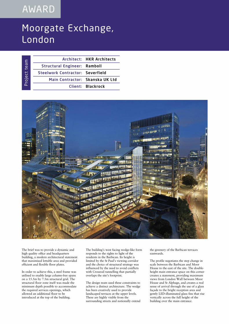
The brief was to provide a dynamic andhigh quality office and headquartersbuilding, a modern architectural statementthat maximised lettable area and providedefficient and flexible floor plates.
In order to achieve this, a steel frame wasutilised to enable large column-free spanson a 15.5m by 7.5m structural grid. Thestructural floor zone itself was made theminimum depth possible to accommodatethe required services openings, whichallowed an additional floor to beintroduced at the top of the building.
The building’s west facing wedge-like formresponds to the rights to light of theresidents in the Barbican. Its height islimited by the St Paul’s viewing corridorand the choice of structural strategy wasinfluenced by the need to avoid conflictswith Crossrail tunnelling that partiallyoverlaps the site’s footprint.
The design team used these constraints toachieve a distinct architecture. The wedgehas been creatively used to providelandscaped terraces at the upper levels.These are highly visible from thesurrounding streets and notionally extend
the greenery of the Barbican terraceseastwards.
The profile negotiates the step change inscale between the Barbican and MoorHouse to the east of the site. The double-height main entrance space on this cornercreates a statement, providing maximumviews from London Wall between MoorHouse and St Alphage, and creates a realsense of arrival through the use of a glassfaçade to the bright reception area andgently LED-illuminated glass fins that risevertically across the full height of thebuilding over the main entrance.
AWARD
Architect: HKR Architects
Structural Engineer: Ramboll
Steelwork Contractor: Severfield
Main Contractor: Skanska UK Ltd
Client: BlackrockProject team
The team maximised the net lettable space by exploitingthe great benefits of a steel frame - long clear spans withminimal fire-engineered columns, and with a reducedoverall floor depth that enabled the incorporation of anadditional storey. Level access to external balconies wasa clever bonus. The lightweight superstructure permitteda raft foundation, impossible with other solutions.
A commercial success thanks to intelligent steelwork.
Judges’ comment
Internally, the large central atrium drawsnatural light into the adjacent officeaccommodation. A combination of high-specification glazing and external shadingprevents overheating on sunny days.Energy-efficient LED light fittings, withdaylight sensor control, will ensure thatlights are switched off when adequatedaylighting is available and the buildingfabric u-values and infiltration exceed PartL 2006 requirements.
Rainwater harvesting coupled with anonsite attenuation tank and a greywaterrecycling plant reduces stormwater run-offand mains water consumption.
By utilising steel rather than concrete, thebuilding was able to achieve long column-free spans as well as reducing the overallfloor zone, increasing the maximumnumber of storeys, and increasing the netlettable space for the client due to fewerand smaller columns.
The speed of construction for the framewas quicker compared to concrete frameoptions and, in addition, the lightweightsuperstructure frame allowed a raftfoundation to be used. This would not havebeen possible with a concrete
superstructure which would have needed apiled foundation solution, increasingconstruction time and cost.
The complex terrace transfer system alsowould not have been anywhere near asefficient without the use of steel, while thestructure is also far more adaptable tofuture tenant changes than a concreteequivalent would be.
The steel frame was designed andrationalised to allow easier fabrication ofthe elements. This included using standardplate thicknesses which could be used tofabricate a number of different beams.
The steel frame was designed to be erectedclose behind the slip formed cores, whichprovided stability to the structure.Provision for a tower crane through thefloor plates was included in the base floordesign, and the design of the columns wasclosely coordinated with the steelworkcontractor’s preferred splice connections.
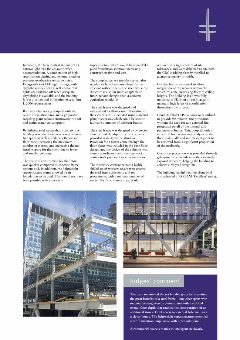
The steelwork contractor had a highlyskilled set of workers onsite who erectedthe steel frame efficiently and onprogramme, with a minimal number ofsnags. The ‘V’ columns in particular
required very tight control of sitetolerances, and were delivered to site withthe GRC cladding already installed toguarantee quality of finish.
Cellular beams were used to allowintegration of the services within thestructural zone, increasing floor-to-ceilingheights. The building itself was fullymodelled in 3D from an early stage tomaintain high levels of coordinationthroughout the project.
Concrete filled CHS columns were utilisedto provide 90 minutes’ fire protectionwithout the need for any external fireprotection on all of the internal andperimeter columns. This, coupled with astructural fire engineering analysis on thefloor plates, allowed intumescent paint tobe removed from a significant proportionof the steelwork.
Corrosion protection was provided throughgalvanized steel members in the externallyexposed structure, helping the building toachieve a 50-year design life.
The building has fulfilled the client briefand achieved a BREEAM ‘Excellent’ rating.
First World War Galleries, Imperial War Museum, London
The Imperial War Museum (IWM) wasfounded in 1917 and moved to the site inLambeth on 7 July 1936. Since then it hasbeen refurbished on numerous occasionsover its history.
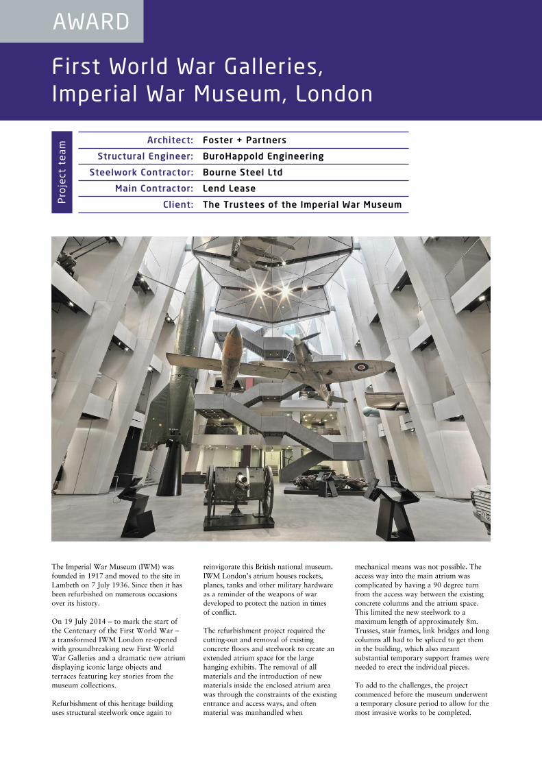
On 19 July 2014 – to mark the start ofthe Centenary of the First World War – a transformed IWM London re-openedwith groundbreaking new First WorldWar Galleries and a dramatic new atriumdisplaying iconic large objects andterraces featuring key stories from themuseum collections.
Refurbishment of this heritage buildinguses structural steelwork once again to
reinvigorate this British national museum.IWM London’s atrium houses rockets,planes, tanks and other military hardwareas a reminder of the weapons of wardeveloped to protect the nation in times of conflict.
The refurbishment project required thecutting-out and removal of existingconcrete floors and steelwork to create anextended atrium space for the largehanging exhibits. The removal of allmaterials and the introduction of newmaterials inside the enclosed atrium areawas through the constraints of the existingentrance and access ways, and oftenmaterial was manhandled when
mechanical means was not possible. Theaccess way into the main atrium wascomplicated by having a 90 degree turnfrom the access way between the existingconcrete columns and the atrium space.This limited the new steelwork to amaximum length of approximately 8m.Trusses, stair frames, link bridges and longcolumns all had to be spliced to get themin the building, which also meantsubstantial temporary support frames wereneeded to erect the individual pieces.
To add to the challenges, the projectcommenced before the museum underwenta temporary closure period to allow for themost invasive works to be completed.
AWARD
Architect: Foster + Partners
Structural Engineer: BuroHappold Engineering
Steelwork Contractor: Bourne Steel Ltd
Main Contractor: Lend Lease
Client: The Trustees of the Imperial War MuseumProject team
A dramatic new atrium has been built within the transformed museum. Angularand robust structures frame new galleries and support war machines in acathedral-like space. Steel construction uniquely allowed constraints of accessand time to be well-answered. The visitor route is now clear and exciting.
A strong sign of success is that visitor numbers have doubled in the year.
Judges’ comment
Therefore, removal of the existinghanging exhibits from the barrel vaultroof and the survey of the existingstructure had to be carried outsimultaneously as night-time working.
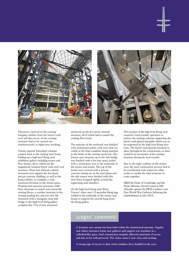
Twenty tapered Vierendeel columnsconnect back to the existing steel frame,holding up a high level flying steelexhibition gallery including trusses andfloor beams, above which sits themagnificent retained barrel vault steel roofstructure. These new intricate columnstructures now support the fair-facedprecast concrete cladding, as well as thehung exhibits, to complete a crispstructural elevation to the atrium space.Floating steel staircase structures, infillfloor structures to match and extend theexisting floors, a corridor structure in theexisting loading bay and two new liftstructures with a triangular truss linkbridge to the high level flying gallerycomplete this 370t of new structural
steelwork on the five storey internalstructure, all of which had to match theexisting floor levels.
The majority of the steelwork was finishedwith intumescent paint, with areas that arevisible in the final condition being matchedto the finish of the existing steelwork. Thefeature stair structure up to the link bridgewas finished with a hot zinc spray sealedwith a renaissance wax to the underside ofthe trusses and treads. The top of thetreads were covered with a precastconcrete nosing sat on the steel plates andthe side trusses were finished with thinsteel sheet wrapped tightly around thesupporting steel members.
On the high level flying steel ‘RoofTerrace’, there were 12 specialist lifting lugswelded to the underside of the trusses andbeams to support the aircraft hung fromthe flying gallery.
The erection of the high level flying steelrequired a load transfer operation toremove the existing columns supporting thebarrel vault glazed end gable which was tobe supported by the high level flying steeltruss. The barrel vault glazing remained inplace throughout the construction, so therecould be no movement of the existingstructure during the load transfer.
Due to the tight confines of the atriumarea, the steel construction process had tobe coordinated with numerous othertrades to enable the final structure tocome together.
HRH the Duke of Cambridge and thePrime Minister, David Cameron MP,officially opened the IWM London’s newFirst World War Galleries following therefurbishment in July 2014.
Derby Arena
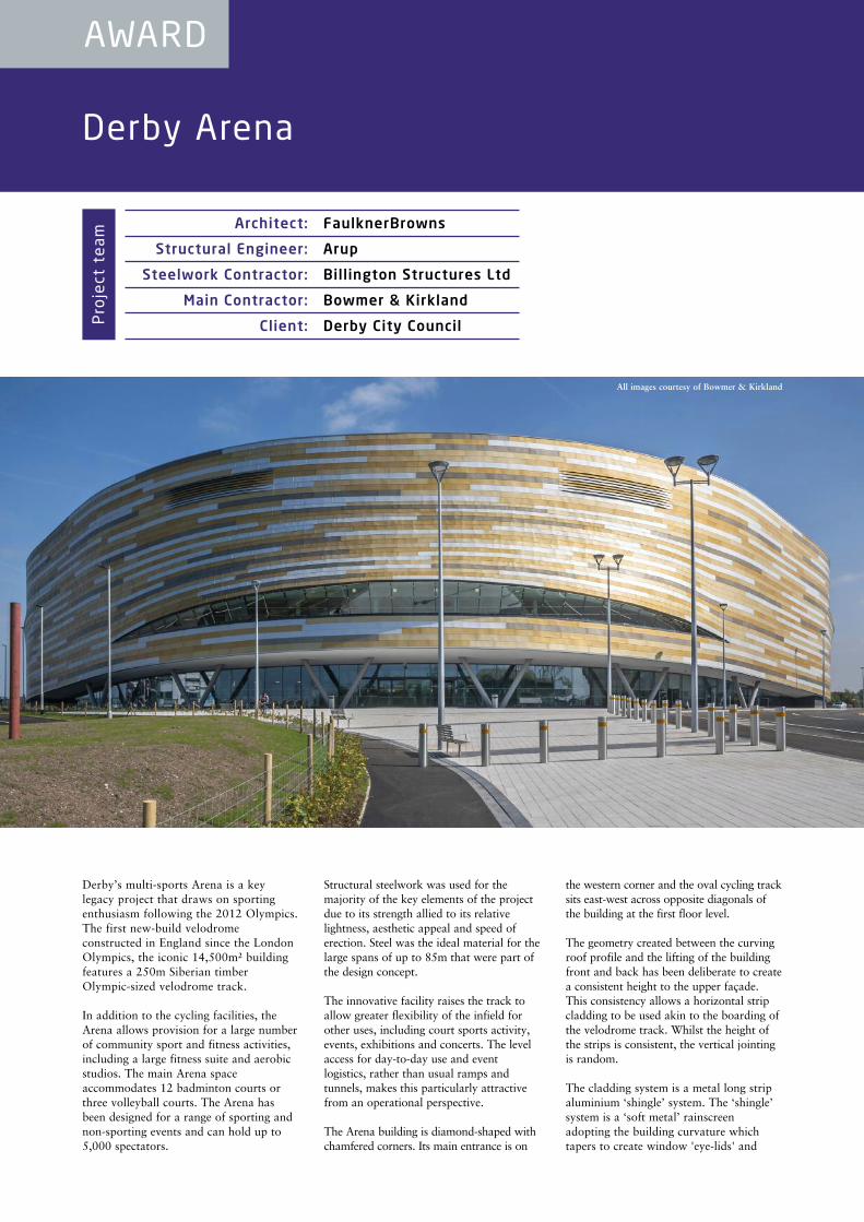
Derby’s multi-sports Arena is a keylegacy project that draws on sportingenthusiasm following the 2012 Olympics.The first new-build velodromeconstructed in England since the LondonOlympics, the iconic 14,500m² buildingfeatures a 250m Siberian timberOlympic-sized velodrome track.
In addition to the cycling facilities, theArena allows provision for a large numberof community sport and fitness activities,including a large fitness suite and aerobicstudios. The main Arena spaceaccommodates 12 badminton courts orthree volleyball courts. The Arena hasbeen designed for a range of sporting andnon-sporting events and can hold up to5,000 spectators.
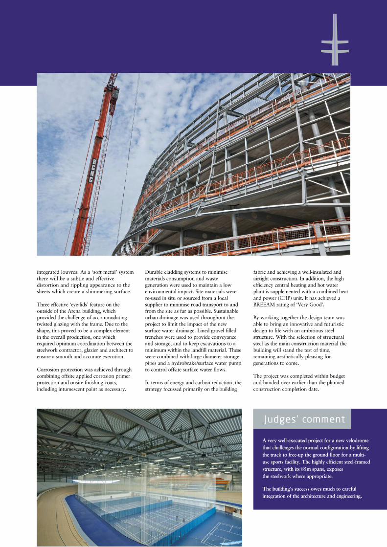
Structural steelwork was used for themajority of the key elements of the projectdue to its strength allied to its relativelightness, aesthetic appeal and speed oferection. Steel was the ideal material for thelarge spans of up to 85m that were part ofthe design concept.
The innovative facility raises the track toallow greater flexibility of the infield forother uses, including court sports activity,events, exhibitions and concerts. The levelaccess for day-to-day use and eventlogistics, rather than usual ramps andtunnels, makes this particularly attractivefrom an operational perspective.
The Arena building is diamond-shaped withchamfered corners. Its main entrance is on
the western corner and the oval cycling tracksits east-west across opposite diagonals ofthe building at the first floor level.
The geometry created between the curvingroof profile and the lifting of the buildingfront and back has been deliberate to createa consistent height to the upper façade.This consistency allows a horizontal stripcladding to be used akin to the boarding ofthe velodrome track. Whilst the height ofthe strips is consistent, the vertical jointingis random.
The cladding system is a metal long stripaluminium ‘shingle’ system. The ‘shingle’system is a ‘soft metal’ rainscreenadopting the building curvature whichtapers to create window 'eye-lids' and
AWARD
Architect: FaulknerBrowns
Structural Engineer: Arup
Steelwork Contractor: Billington Structures Ltd
Main Contractor: Bowmer & Kirkland
Client: Derby City CouncilProject team
All images courtesy of Bowmer & Kirkland
integrated louvres. As a ‘soft metal’ systemthere will be a subtle and effectivedistortion and rippling appearance to thesheets which create a shimmering surface.
Three effective ‘eye-lids’ feature on theoutside of the Arena building, whichprovided the challenge of accommodatingtwisted glazing with the frame. Due to theshape, this proved to be a complex elementin the overall production, one whichrequired optimum coordination between thesteelwork contractor, glazier and architect toensure a smooth and accurate execution.
Corrosion protection was achieved throughcombining offsite applied corrosion primerprotection and onsite finishing coats,including intumescent paint as necessary.
Durable cladding systems to minimisematerials consumption and wastegeneration were used to maintain a lowenvironmental impact. Site materials werere-used in situ or sourced from a localsupplier to minimise road transport to andfrom the site as far as possible. Sustainableurban drainage was used throughout theproject to limit the impact of the newsurface water drainage. Lined gravel filledtrenches were used to provide conveyanceand storage, and to keep excavations to aminimum within the landfill material. Thesewere combined with large diameter storagepipes and a hydrobrake/surface water pumpto control offsite surface water flows.
In terms of energy and carbon reduction, thestrategy focussed primarily on the building
fabric and achieving a well-insulated andairtight construction. In addition, the highefficiency central heating and hot waterplant is supplemented with a combined heatand power (CHP) unit. It has achieved aBREEAM rating of ‘Very Good’.
By working together the design team wasable to bring an innovative and futuristicdesign to life with an ambitious steelstructure. With the selection of structuralsteel as the main construction material thebuilding will stand the test of time,remaining aesthetically pleasing forgenerations to come.
The project was completed within budgetand handed over earlier than the plannedconstruction completion date.
A very well-executed project for a new velodromethat challenges the normal configuration by liftingthe track to free-up the ground floor for a multi-use sports facility. The highly efficient steel-framedstructure, with its 85m spans, exposes the steelwork where appropriate.
The building’s success owes much to carefulintegration of the architecture and engineering.
Judges’ comment

Merchant Square Footbridge,London
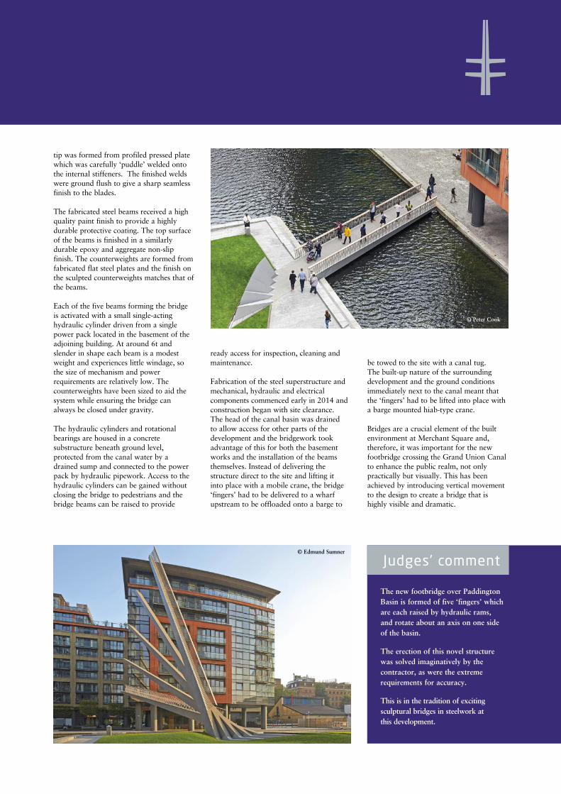
The new moving footbridge at MerchantSquare in Paddington is a 3m widecantilevered structure which spans 20macross the Grand Union Canal, and isdivided into five slender ‘fingers’ which areraised using hydraulic jacks with an actionsimilar to that of a traditional Japanesehand fan.
The fabricated steel beams forming thedeck open in sequence, with the first risingto an angle of 70 degrees and the lastachieving the required clearance over thecanal of 2.5m tall by 5.5m wide at mid-channel. Shaped counterweights assist thehydraulic mechanism and reduce the energyrequired to move the structure. The bridgebalustrades are formed from twin rows of
inclined stainless steel rods overlapping toform a robust, yet filigree and highlytransparent, structure. The handrail housesa continuous low energy LED downlightwhich provides excellent and uniformfunctional illumination of the walkingsurface and the edge, as well as offering anattractive lighting feature.
The relatively modest span suggested thatonly vertical movement would offer thedrama sought in the brief. Constraints onland ownership dictated the bridgestructure should be supported primarilyfrom the north end, with only limitedsupport provided on the south bank.Simplifying maintenance was a key driver -by dividing the beam into five discrete
‘fingers’ the duty on the hydraulics requiredto raise the beam is significantly reduced.
The design of the footbridge structurerelied very much on the steelworkcontractor’s ability to manufacture the five‘fingers’ to exacting tolerances. When in itslowered position the five slender steel‘fingers’ had to effectively create a flat,almost seamless, walking surface. The five‘fingers’ were set up in bespoke jigs whichwere used to control the critical dimensionsand limit distortion caused by the weldingprocess. Each ‘finger’ also had a sculpturedblade at each end, which not only held theballast needed to balance the bridge butalso formed a vital component in theoverall aesthetics of the bridge. Each blade
AWARD
Architect: Knight Architects
Structural Engineer: AKT II
Steelwork Contractor: S H Structures Ltd
Main Contractor: Mace Ltd
Client: European Land & Property LtdProject team
© Edmund Sumner
tip was formed from profiled pressed platewhich was carefully ‘puddle’ welded ontothe internal stiffeners. The finished weldswere ground flush to give a sharp seamlessfinish to the blades.
The fabricated steel beams received a highquality paint finish to provide a highlydurable protective coating. The top surfaceof the beams is finished in a similarlydurable epoxy and aggregate non-slipfinish. The counterweights are formed fromfabricated flat steel plates and the finish onthe sculpted counterweights matches that ofthe beams.
Each of the five beams forming the bridgeis activated with a small single-actinghydraulic cylinder driven from a singlepower pack located in the basement of theadjoining building. At around 6t andslender in shape each beam is a modestweight and experiences little windage, sothe size of mechanism and powerrequirements are relatively low. Thecounterweights have been sized to aid thesystem while ensuring the bridge canalways be closed under gravity.
The hydraulic cylinders and rotationalbearings are housed in a concretesubstructure beneath ground level,protected from the canal water by adrained sump and connected to the powerpack by hydraulic pipework. Access to thehydraulic cylinders can be gained withoutclosing the bridge to pedestrians and thebridge beams can be raised to provide
ready access for inspection, cleaning andmaintenance.
Fabrication of the steel superstructure andmechanical, hydraulic and electricalcomponents commenced early in 2014 andconstruction began with site clearance. The head of the canal basin was drained to allow access for other parts of thedevelopment and the bridgework tookadvantage of this for both the basementworks and the installation of the beamsthemselves. Instead of delivering thestructure direct to the site and lifting it into place with a mobile crane, the bridge‘fingers’ had to be delivered to a wharfupstream to be offloaded onto a barge to
be towed to the site with a canal tug. The built-up nature of the surroundingdevelopment and the ground conditionsimmediately next to the canal meant thatthe ‘fingers’ had to be lifted into place witha barge mounted hiab-type crane.
Bridges are a crucial element of the builtenvironment at Merchant Square and,therefore, it was important for the newfootbridge crossing the Grand Union Canalto enhance the public realm, not onlypractically but visually. This has beenachieved by introducing vertical movementto the design to create a bridge that ishighly visible and dramatic.
The new footbridge over PaddingtonBasin is formed of five ‘fingers’ whichare each raised by hydraulic rams,and rotate about an axis on one sideof the basin.
The erection of this novel structurewas solved imaginatively by thecontractor, as were the extremerequirements for accuracy.
This is in the tradition of excitingsculptural bridges in steelwork at this development.
Judges’ comment© Edmund Sumner
© Peter Cook
Island Pavilion and Footbridge, Wormsley
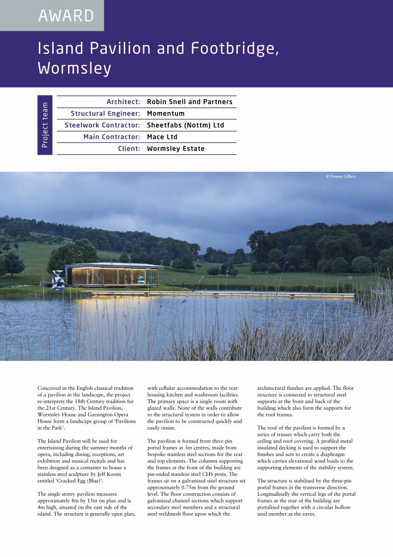
Conceived in the English classical traditionof a pavilion in the landscape, the projectre-interprets the 18th Century tradition forthe 21st Century. The Island Pavilion,Wormsley House and Garsington OperaHouse form a landscape group of ‘Pavilionsin the Park’.
The Island Pavilion will be used forentertaining during the summer months ofopera, including dining, receptions, artexhibition and musical recitals and hasbeen designed as a container to house astainless steel sculpture by Jeff Koonsentitled ‘Cracked Egg (Blue)’.
The single storey pavilion measuresapproximately 8m by 15m on plan and is4m high, situated on the east side of theisland. The structure is generally open plan,
with cellular accommodation to the rearhousing kitchen and washroom facilities.The primary space is a single room withglazed walls. None of the walls contributeto the structural system in order to allowthe pavilion to be constructed quickly andeasily onsite.
The pavilion is formed from three-pinportal frames at 3m centres, made frombespoke stainless steel sections for the rearand top elements. The columns supportingthe frames at the front of the building arepin-ended stainless steel CHS posts. Theframes sit on a galvanized steel structure setapproximately 0.75m from the groundlevel. The floor construction consists ofgalvanized channel sections which supportsecondary steel members and a structuralsteel weldmesh floor upon which the
architectural finishes are applied. The floorstructure is connected to structural steelsupports at the front and back of thebuilding which also form the supports forthe roof frames.
The roof of the pavilion is formed by aseries of trusses which carry both theceiling and roof covering. A profiled metalinsulated decking is used to support thefinishes and acts to create a diaphragmwhich carries elevational wind loads to thesupporting elements of the stability system.
The structure is stabilised by the three-pinportal frames in the transverse direction.Longitudinally the vertical legs of the portalframes at the rear of the building areportalised together with a circular hollowsteel member at the eaves.
AWARD
Architect: Robin Snell and Partners
Structural Engineer: Momentum
Steelwork Contractor: Sheetfabs (Nottm) Ltd
Main Contractor: Mace Ltd
Client: Wormsley EstateProject team
© Dennis Gilbert
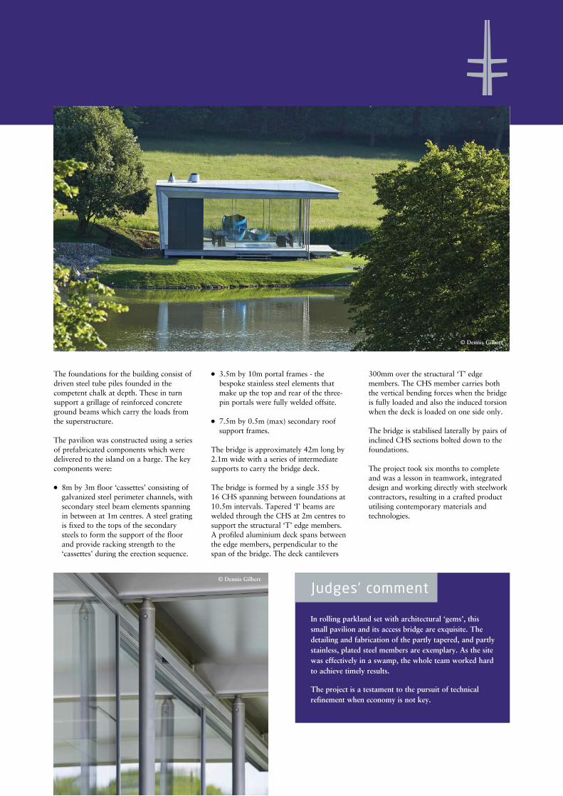
In rolling parkland set with architectural ‘gems’, thissmall pavilion and its access bridge are exquisite. Thedetailing and fabrication of the partly tapered, and partlystainless, plated steel members are exemplary. As the sitewas effectively in a swamp, the whole team worked hardto achieve timely results.
The project is a testament to the pursuit of technicalrefinement when economy is not key.
Judges’ comment
The foundations for the building consist ofdriven steel tube piles founded in thecompetent chalk at depth. These in turnsupport a grillage of reinforced concreteground beams which carry the loads fromthe superstructure.
The pavilion was constructed using a seriesof prefabricated components which weredelivered to the island on a barge. The keycomponents were:
l 8m by 3m floor ‘cassettes’ consisting ofgalvanized steel perimeter channels, withsecondary steel beam elements spanningin between at 1m centres. A steel gratingis fixed to the tops of the secondarysteels to form the support of the floorand provide racking strength to the‘cassettes’ during the erection sequence.
l 3.5m by 10m portal frames - thebespoke stainless steel elements thatmake up the top and rear of the three-pin portals were fully welded offsite.
l 7.5m by 0.5m (max) secondary roofsupport frames.
The bridge is approximately 42m long by2.1m wide with a series of intermediatesupports to carry the bridge deck.
The bridge is formed by a single 355 by 16 CHS spanning between foundations at10.5m intervals. Tapered ‘I’ beams arewelded through the CHS at 2m centres tosupport the structural ‘T’ edge members. A profiled aluminium deck spans betweenthe edge members, perpendicular to thespan of the bridge. The deck cantilevers
300mm over the structural ‘T’ edgemembers. The CHS member carries boththe vertical bending forces when the bridgeis fully loaded and also the induced torsionwhen the deck is loaded on one side only.
The bridge is stabilised laterally by pairs ofinclined CHS sections bolted down to thefoundations.
The project took six months to completeand was a lesson in teamwork, integrateddesign and working directly with steelworkcontractors, resulting in a crafted productutilising contemporary materials andtechnologies.
© Dennis Gilbert
© Dennis Gilbert
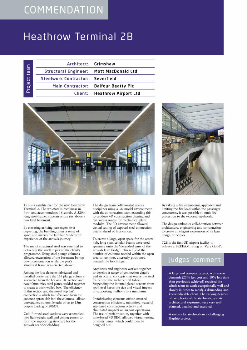
T2B is a satellite pier for the new HeathrowTerminal 2. The structure is rectilinear inform and accommodates 16 stands. A 520mlong steel-framed superstructure sits above atwo level basement.
By elevating arriving passengers overdeparting, the building offers a sense ofspace and inverts the familiar ‘undercroft’experience of the arrivals journey.
The use of structural steel was essential todelivering the satellite pier to the client’sprogramme. Using steel plunge columnsallowed excavation of the basement by top-down construction while the pier’sstructural frame was erected above.
Among the first elements fabricated andinstalled onsite were the 163 plunge columns,assembled from the heaviest UC section andtwo 40mm thick steel plates, welded togetherto create a thick-walled box. The efficiencyof this section and the novel ‘top hat’connection – which transfers load from theconcrete apron slab into the columns - allowsunrestrained column lengths of up to 15mdespite loading of 20MN.
Cold-formed steel sections were assembledinto lightweight wall and ceiling panels toform the supporting structure for thearrivals corridor cladding.
The design team collaborated acrossdisciplines using a 3D model environment,with the construction team extending thisto produce 4D construction phasing andtest access routes for mechanical plantmodules. The 3D environment allowedvirtual testing of exposed steel connectiondetails ahead of fabrication.
To create a large, open space for the centralhub, long-span cellular beams were usedspanning onto the Vierendeel truss of thearrivals level bridge. This reduced thenumber of columns needed within the openarea to just two, discretely positionedbeneath the footbridge.
Architects and engineers worked togetherto develop a range of connection detailsand structural concepts that weave the steelframe into the architectural fabric.Suspending the internal glazed screens fromroof level keeps the size and visual impactof supporting mullions to a minimum.
Prefabricating elements offsite ensuredconstruction efficiency, minimised wastefulsite-based construction activity andeliminated impacts on airport operations.The use of prefabrication, together withtime-based 4D BIM, allowed virtual testingof safety issues, which could then bedesigned out.
By taking a fire engineering approach andlimiting the fire load within the passengerconcourses, it was possible to omit fireprotection to the exposed steelwork.
The design embodies collaboration betweenarchitecture, engineering and constructionto create an elegant expression of its leandesign principles.
T2B is the first UK airport facility toachieve a BREEAM rating of ‘Very Good’.
Heathrow Terminal 2B
COMMENDATION
A large and complex project, with severedemands (25% less cost and 10% less timethan previously achieved) required thewhole team to work exceptionally well andclosely in order to satisfy a demanding andknowledgeable client. The varying degreesof complexity of the steelwork, and itsarchitectural exposure, were very wellplanned, detailed and executed.
A success for steelwork in a challengingflagship project.
Judges’ comment
Architect: Grimshaw
Structural Engineer: Mott MacDonald Ltd
Steelwork Contractor: Severfield
Main Contractor: Balfour Beatty Plc
Client: Heathrow Airport LtdProject team

Milton Court, Guildhall School of Music & Drama
COMMENDATION
A highly complex project on a dense urbansite, with severe acoustic demands due totraffic noise and underground trains, andisolation between separate performancespaces. The solution is ‘box-in-box’construction, whereby each performancespace is constructed of steelwork built within,and isolated from, the concrete substructure.
Steelwork is key to this world-class music anddrama facility.
Judges’ comment
Architect: RHWL Arts Team
Structural Engineer: WSP Cantor Seinuk
Steelwork Contractor: William Hare Ltd
Main Contractor: Sir Robert McAlpine Ltd
Client: Heron Land Developments
Milton Court is a new £89m facility builtfor the Guildhall School of Music &Drama. Located near the Barbican, itoccupies two basement levels and the firstsix floors of the development. It includes aworld-class 609-seat concert hall, twotheatres, rehearsal rooms, office space, aTV studio suite, a lobby and bar, as well asan impressive roof garden.
The concert hall and studio theatre weredesigned to meet very high acousticperformance requirements utilising a ‘box-in-box’ principle. Due to the smallfootprint of the site, a steel ‘box-in-box’system gave the benefit of acousticallyisolating each internal part of the buildingfrom one another. Acoustic isolation wasachieved by adopting an internal steelframe encased in concrete with wallsconstructed out of dense blockwork.
The studio also had a composite slab roofand an internal acoustically separatedsuspended floor slab. Every element of thestructure was seated on isolation bearings.
The acoustically isolated suspended floorslab was constructed utilising Omnia unitsspanning between upturned steel ‘T’sections, which in turn were seated on pre-levelled and grouted acoustic bearings.Once all of the units were in place, thewhole area had to be completely sealedprior to concreting to prevent any groutleak and consequently a breach of theacoustic isolation.
Due to all columns being seated onbearings this necessitated considerabletemporary works to stabilise each structureduring construction. To compound theproblem the steelwork contractor was notpermitted to connect to the adjacent wallsdue to the high quality finish. Additionally,in the basement studio theatre, temporaryconnections were not permitted to the floorslab due to the risk of penetrating thewaterproofing membrane.
A high quality, high resilience naturalrubber was used for all the isolationbearings and they were locked into placeduring the construction. By isolating thesteel structure the construction timeincreased as bolted connections had to becarefully designed and installed.
The construction of the main towerstructure was well in advance of level 6before the commencement of the steelerection. This meant that the internalsteelwork to the studio theatre had to beerected within a closed concrete box. As a consequence, early coordination wasrequired to ensure timely supply of liftingbeams and lifting lugs to be cast into thetheatre roof slab to facilitate erection of thestructural steel.
The hall now has the largest audiencecapacity of any London conservatoirewhich makes it an ideal stage to showcasethe talents of the school’s musicians.
Project team

Long planned as part of the development atGreenwich Reach, the bridge provides avalued link for residents to access publictransport links and local attractions.
The bridge has a 44m cable stayed mainspan supported from a single mast with acentral stay plane. A short 8m backspancontains a 120t counterweight to balance thestructure. Two pairs of backstays support thetip of the mast laterally and longitudinally.
The structure is supported on a 3.7mdiameter slewing ring bearing underneaththe mast, with a set of four electric motorsto drive the bridge clear of the navigationchannel concealed in the machine roomwithin the main concrete pier.
To swing the bridge across the channel, thedrive motors rotate the bridge through 110degrees. As it reaches the end of the swing,two stainless steel nose wheels engage withramps on the west abutment to lift the noseupwards into its service position. Anelectrically actuated locking pin thenengages to provide a nose restraint againstextreme lateral loads.
Faceted planes create an elegant and visuallymassive backspan and reduce to a moreslender main span with a central spine box
supporting diagonal struts to the edge of thedeck. The plated concept is continuedthrough the main mast, where two verticalflat plates supported by diagonal stiffenerscreate an innovative open Vierendeel typestructure. The inclined web plates createopenings to the sky to lighten theappearance for maximum transparency.
Steel is crucial to ensuring that the movingspan is as light as possible. By usingexternally painted weathering steel forclosed sections, any requirement for internalinspection and maintenance has beenremoved.
Rolled ‘T’ section struts are used to supportthe edge of the deck, creating a thin edgebeam and hence a slender appearance. Thestruts are inclined in plan and elevation tocreate a lightweight space truss to enhancethe torsional stiffness of the deck supportedby the central stay plane.
To minimise onsite welding and meet a tightconstruction programme, sections of thebridge were prefabricated offsite andbrought to site by road. The structure wasdesigned to facilitate easy fabrication, andthe designers worked closely with thesteelwork contractors to ensure aneconomic construction process.
The sections were craned into place in theopen position before the backspancounterweights were installed and sitewelding completed.
The bridge provides an exciting link forpedestrians while still maintaining athoroughfare for marine navigation.
Greenwich Reach Swing Bridge, London
COMMENDATION
Through simplicity of form and operation,and structural efficiency, this bridge isexemplary in its use and expression ofplated steelwork. It has become a thrivingroute for cyclists and pedestrians, linkingthe new communities of Deptford Creek.
At the mouth of the Creek, this forms aneffective and attractive feature of themaritime landscape of the Thames.
Judges’ comment
Architect: Moxon Architects
Structural Engineer: Flint & Neill Ltd
Steelwork Contractor: S H Structures Ltd
Main Contractor: Raymond Brown Construction Ltd
Client: Galliard Homes LtdProject team
Kew House, Richmond
CERTIFICATE OF MERIT
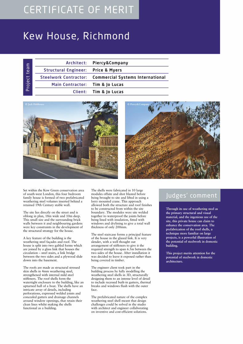
Through its use of weathering steel asthe primary structural and visualmaterial, and the ingenious use of thesite, this private house can claim toenhance the conservation area. Theprefabrication of the roof shells, atechnique more familiar on largeprojects, is a powerful illustration ofthe potential of steelwork in domesticbuilding.
This project merits attention for thepotential of steelwork in domesticarchitecture.
Judges’ commentSet within the Kew Green conservation areaof south-west London, this four bedroomfamily house is formed of two prefabricatedweathering steel volumes inserted behind aretained 19th Century stable wall.
The site lies directly on the street and isoblong in plan, 18m wide and 10m deep.This small size and the surrounding brickwalls between it and neighbouring gardenswere key constraints in the development ofthe structural strategy for the house.
A key feature of the building is theweathering steel façades and roof. Thehouse is split into two gabled forms whichare joined by a glass link that houses thecirculation – steel stairs, a link bridgebetween the two sides and a plywood slidedown into the basement.
The roofs are made as structural stressedskin shells in 4mm weathering steel,strengthened with internal mild steelstiffeners. The roof shells form thewatertight enclosure to the building, like anupturned hull of a boat. The shells have anintricate array of details, includingperforations, expressed welded joints andconcealed gutters and drainage channelsaround window openings, that retain theirclean lines whilst making the shellsfunctional as a building.
The shells were fabricated in 10 largemodules offsite and shot blasted beforebeing brought to site and lifted in using alorry mounted crane. This approachallowed both the structure and roof finishesto be constructed from within the siteboundary. The modules were site weldedtogether to waterproof the joints beforebeing lined with insulation, fitted withwindows and drylining to give a total wallthickness of only 200mm.
The steel staircase forms a principal featureof the house in the glazed link. It is veryslender, with a well thought outarrangement of stiffeners to give it therequired strength to span 6.5m between thetwo sides of the house. After installation itwas decided to leave it exposed rather thanbeing covered in timber.
The engineer client took part in thebuilding process by fully modelling theweathering steel shells in 3D, structurallydesigning them to an intense level of detailto include recessed built-in gutters, thermalbreaks and windows flush with the outerface.
The prefabricated nature of the complexweathering steel shell meant that designchallenges could be solved in the studiowith architect and engineer collaboratingon inventive and cost-efficient solutions.
Architect: Piercy&Company
Structural Engineer: Price & Myers
Steelwork Contractor: Commercial Systems International
Main Contractor: Tim & Jo Lucas
Client: Tim & Jo LucasProject team
© Jack Hobhouse © Piercy&Company
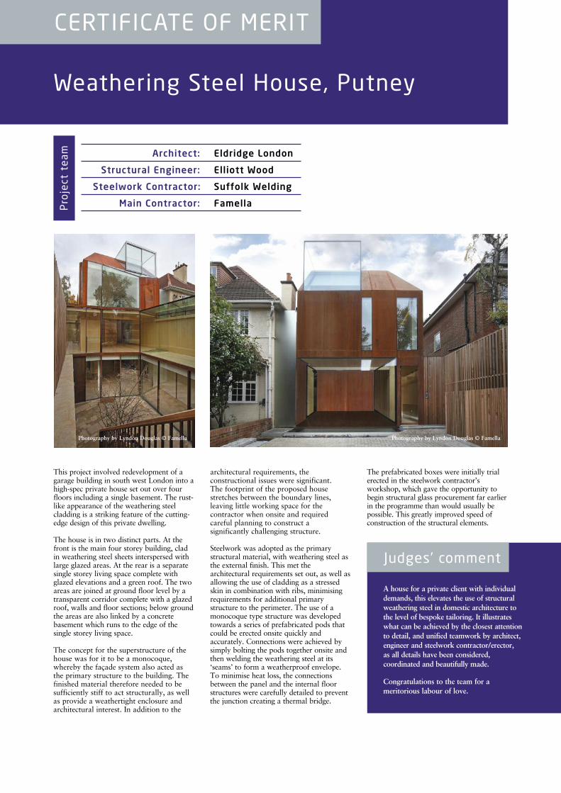
This project involved redevelopment of agarage building in south west London into ahigh-spec private house set out over fourfloors including a single basement. The rust-like appearance of the weathering steelcladding is a striking feature of the cutting-edge design of this private dwelling.
The house is in two distinct parts. At thefront is the main four storey building, cladin weathering steel sheets interspersed withlarge glazed areas. At the rear is a separatesingle storey living space complete withglazed elevations and a green roof. The twoareas are joined at ground floor level by atransparent corridor complete with a glazedroof, walls and floor sections; below groundthe areas are also linked by a concretebasement which runs to the edge of thesingle storey living space.
The concept for the superstructure of thehouse was for it to be a monocoque,whereby the façade system also acted asthe primary structure to the building. Thefinished material therefore needed to besufficiently stiff to act structurally, as wellas provide a weathertight enclosure andarchitectural interest. In addition to the
architectural requirements, theconstructional issues were significant. The footprint of the proposed housestretches between the boundary lines,leaving little working space for thecontractor when onsite and requiredcareful planning to construct a significantly challenging structure.
Steelwork was adopted as the primarystructural material, with weathering steel asthe external finish. This met thearchitectural requirements set out, as well asallowing the use of cladding as a stressedskin in combination with ribs, minimisingrequirements for additional primarystructure to the perimeter. The use of amonocoque type structure was developedtowards a series of prefabricated pods thatcould be erected onsite quickly andaccurately. Connections were achieved bysimply bolting the pods together onsite andthen welding the weathering steel at its‘seams’ to form a weatherproof envelope.To minimise heat loss, the connectionsbetween the panel and the internal floorstructures were carefully detailed to preventthe junction creating a thermal bridge.
The prefabricated boxes were initially trialerected in the steelwork contractor’sworkshop, which gave the opportunity tobegin structural glass procurement far earlierin the programme than would usually bepossible. This greatly improved speed ofconstruction of the structural elements.
Weathering Steel House, Putney
CERTIFICATE OF MERIT
A house for a private client with individualdemands, this elevates the use of structuralweathering steel in domestic architecture tothe level of bespoke tailoring. It illustrateswhat can be achieved by the closest attentionto detail, and unified teamwork by architect,engineer and steelwork contractor/erector, as all details have been considered,coordinated and beautifully made.
Congratulations to the team for ameritorious labour of love.
Judges’ comment
Architect: Eldridge London
Structural Engineer: Elliott Wood
Steelwork Contractor: Suffolk Welding
Main Contractor: FamellaProject team
Photography by Lyndon Douglas © Famella Photography by Lyndon Douglas © Famella
St James’s Gateway, London
NATIONAL FINALIST
Retail Development Plateau, Bargoed
NATIONAL FINALIST
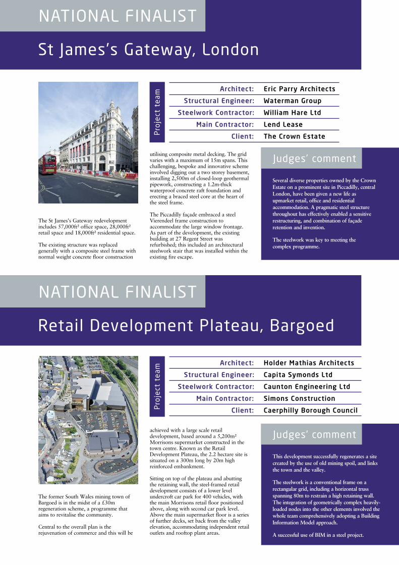
Several diverse properties owned by the CrownEstate on a prominent site in Piccadilly, centralLondon, have been given a new life asupmarket retail, office and residentialaccommodation. A pragmatic steel structurethroughout has effectively enabled a sensitiverestructuring, and combination of façaderetention and invention.
The steelwork was key to meeting the complex programme.
Judges’ comment
The St James’s Gateway redevelopmentincludes 57,000ft² office space, 28,000ft²retail space and 18,000ft² residential space.
The existing structure was replacedgenerally with a composite steel frame withnormal weight concrete floor construction
utilising composite metal decking. The gridvaries with a maximum of 15m spans. Thischallenging, bespoke and innovative schemeinvolved digging out a two storey basement,installing 2,500m of closed-loop geothermalpipework, constructing a 1.2m-thickwaterproof concrete raft foundation anderecting a braced steel core at the heart ofthe steel frame.
The Piccadilly façade embraced a steelVierendeel frame construction toaccommodate the large window frontage.As part of the development, the existingbuilding at 27 Regent Street wasrefurbished; this included an architecturalsteelwork stair that was installed within theexisting fire escape.
Architect: Eric Parry Architects
Structural Engineer: Waterman Group
Steelwork Contractor: William Hare Ltd
Main Contractor: Lend Lease
Client: The Crown Estate
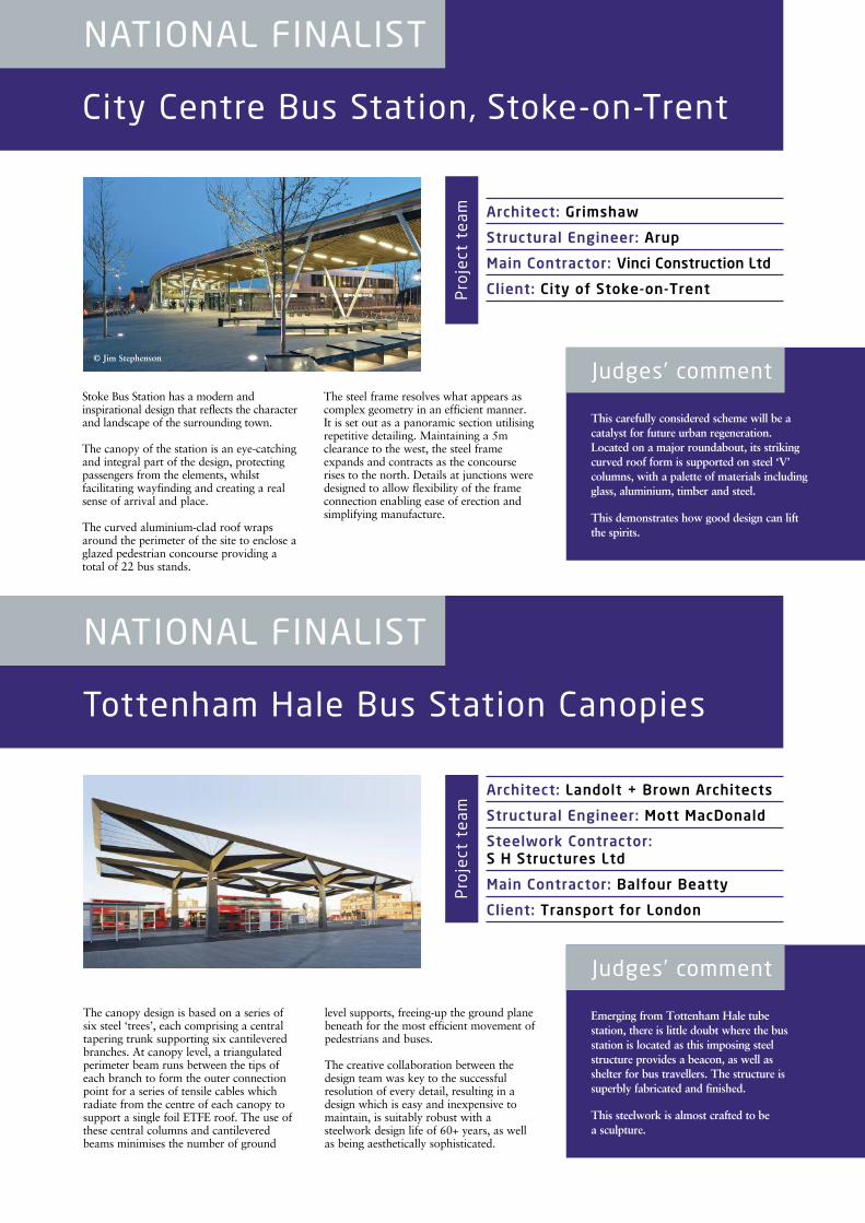
This development successfully regenerates a sitecreated by the use of old mining spoil, and linksthe town and the valley.
The steelwork is a conventional frame on arectangular grid, including a horizontal trussspanning 80m to restrain a high retaining wall.The integration of geometrically complex heavily-loaded nodes into the other elements involved thewhole team comprehensively adopting a BuildingInformation Model approach.
A successful use of BIM in a steel project.
Judges’ comment
The former South Wales mining town ofBargoed is in the midst of a £30mregeneration scheme, a programme thataims to revitalise the community.
Central to the overall plan is therejuvenation of commerce and this will be
achieved with a large scale retaildevelopment, based around a 5,200m²Morrisons supermarket constructed in thetown centre. Known as the RetailDevelopment Plateau, the 2.2 hectare site issituated on a 300m long by 20m highreinforced embankment.
Sitting on top of the plateau and abuttingthe retaining wall, the steel-framed retaildevelopment consists of a lower levelundercroft car park for 400 vehicles, withthe main Morrisons retail floor positionedabove, along with second car park level.Above the main supermarket floor is a seriesof further decks, set back from the valleyelevation, accommodating independent retailoutlets and rooftop plant areas.
Architect: Holder Mathias Architects
Structural Engineer: Capita Symonds Ltd
Steelwork Contractor: Caunton Engineering Ltd
Main Contractor: Simons Construction
Client: Caerphilly Borough Council
Project team
Project team
City Centre Bus Station, Stoke-on-Trent
NATIONAL FINALIST
Tottenham Hale Bus Station Canopies
NATIONAL FINALIST
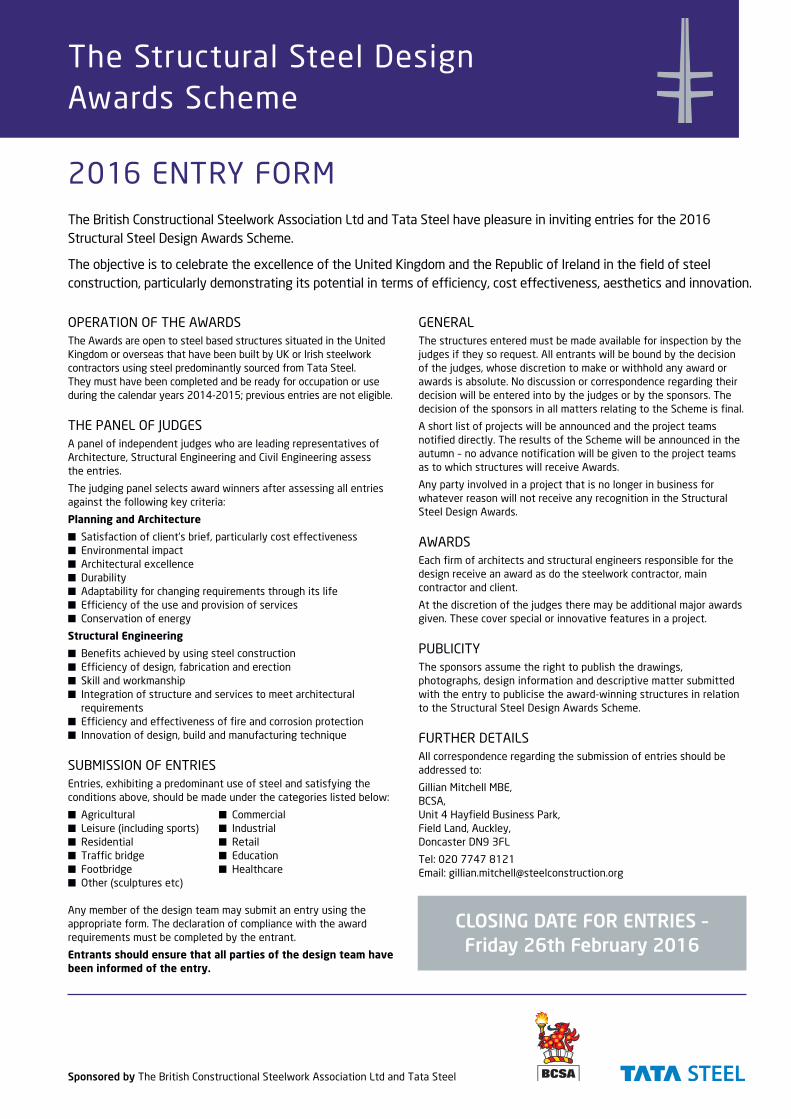
This carefully considered scheme will be acatalyst for future urban regeneration.Located on a major roundabout, its strikingcurved roof form is supported on steel ‘V’columns, with a palette of materials includingglass, aluminium, timber and steel.
This demonstrates how good design can liftthe spirits.
Judges’ comment
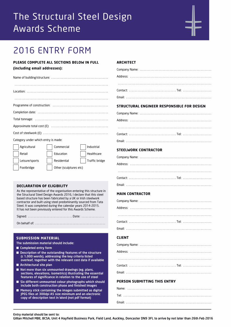
Emerging from Tottenham Hale tubestation, there is little doubt where the busstation is located as this imposing steelstructure provides a beacon, as well asshelter for bus travellers. The structure issuperbly fabricated and finished.
This steelwork is almost crafted to be a sculpture.
Judges’ comment
Architect: Grimshaw
Structural Engineer: Arup
Main Contractor: Vinci Construction Ltd
Client: City of Stoke-on-Trent
Architect: Landolt + Brown Architects
Structural Engineer: Mott MacDonald
Steelwork Contractor: S H Structures Ltd
Main Contractor: Balfour Beatty
Client: Transport for London
The canopy design is based on a series ofsix steel ‘trees’, each comprising a centraltapering trunk supporting six cantileveredbranches. At canopy level, a triangulatedperimeter beam runs between the tips ofeach branch to form the outer connectionpoint for a series of tensile cables whichradiate from the centre of each canopy tosupport a single foil ETFE roof. The use ofthese central columns and cantileveredbeams minimises the number of ground
level supports, freeing-up the ground planebeneath for the most efficient movement ofpedestrians and buses.
The creative collaboration between thedesign team was key to the successfulresolution of every detail, resulting in adesign which is easy and inexpensive tomaintain, is suitably robust with asteelwork design life of 60+ years, as well as being aesthetically sophisticated.
Stoke Bus Station has a modern andinspirational design that reflects the characterand landscape of the surrounding town.
The canopy of the station is an eye-catchingand integral part of the design, protectingpassengers from the elements, whilstfacilitating wayfinding and creating a realsense of arrival and place.
The curved aluminium-clad roof wrapsaround the perimeter of the site to enclose aglazed pedestrian concourse providing atotal of 22 bus stands.
The steel frame resolves what appears ascomplex geometry in an efficient manner. It is set out as a panoramic section utilisingrepetitive detailing. Maintaining a 5mclearance to the west, the steel frameexpands and contracts as the concourserises to the north. Details at junctions weredesigned to allow flexibility of the frameconnection enabling ease of erection andsimplifying manufacture.
Project team
Project team
© Jim Stephenson
The British Constructional Steelwork Association Ltd and Tata Steel have pleasure in inviting entries for the 2016Structural Steel Design Awards Scheme.
The objective is to celebrate the excellence of the United Kingdom and the Republic of Ireland in the field of steelconstruction, particularly demonstrating its potential in terms of efficiency, cost effectiveness, aesthetics and innovation.
The Structural Steel Design Awards Scheme
2016 ENTRY FORM
OPERATION OF THE AWARDSThe Awards are open to steel based structures situated in the UnitedKingdom or overseas that have been built by UK or Irish steelworkcontractors using steel predominantly sourced from Tata Steel. They must have been completed and be ready for occupation or useduring the calendar years 2014-2015; previous entries are not eligible.
THE PANEL OF JUDGESA panel of independent judges who are leading representatives ofArchitecture, Structural Engineering and Civil Engineering assess the entries.
The judging panel selects award winners after assessing all entriesagainst the following key criteria:
Planning and Architecture
■ Satisfaction of client’s brief, particularly cost effectiveness■ Environmental impact■ Architectural excellence■ Durability■ Adaptability for changing requirements through its life■ Efficiency of the use and provision of services■ Conservation of energy
Structural Engineering
■ Benefits achieved by using steel construction■ Efficiency of design, fabrication and erection■ Skill and workmanship■ Integration of structure and services to meet architectural
requirements■ Efficiency and effectiveness of fire and corrosion protection■ Innovation of design, build and manufacturing technique
SUBMISSION OF ENTRIESEntries, exhibiting a predominant use of steel and satisfying theconditions above, should be made under the categories listed below:
■ Agricultural ■ Commercial■ Leisure (including sports) ■ Industrial■ Residential ■ Retail■ Traffic bridge ■ Education■ Footbridge ■ Healthcare■ Other (sculptures etc)
Any member of the design team may submit an entry using theappropriate form. The declaration of compliance with the awardrequirements must be completed by the entrant.
Entrants should ensure that all parties of the design team havebeen informed of the entry.
GENERALThe structures entered must be made available for inspection by thejudges if they so request. All entrants will be bound by the decisionof the judges, whose discretion to make or withhold any award orawards is absolute. No discussion or correspondence regarding theirdecision will be entered into by the judges or by the sponsors. Thedecision of the sponsors in all matters relating to the Scheme is final.
A short list of projects will be announced and the project teamsnotified directly. The results of the Scheme will be announced in theautumn – no advance notification will be given to the project teamsas to which structures will receive Awards.
Any party involved in a project that is no longer in business forwhatever reason will not receive any recognition in the StructuralSteel Design Awards.
AWARDSEach firm of architects and structural engineers responsible for thedesign receive an award as do the steelwork contractor, maincontractor and client.
At the discretion of the judges there may be additional major awardsgiven. These cover special or innovative features in a project.
PUBLICITYThe sponsors assume the right to publish the drawings,photographs, design information and descriptive matter submittedwith the entry to publicise the award-winning structures in relationto the Structural Steel Design Awards Scheme.
FURTHER DETAILSAll correspondence regarding the submission of entries should beaddressed to:
Gillian Mitchell MBE, BCSA, Unit 4 Hayfield Business Park,Field Land, Auckley, Doncaster DN9 3FL
Tel: 020 7747 8121Email: [email protected]
CLOSING DATE FOR ENTRIES –Friday 26th February 2016
Sponsored by The British Constructional Steelwork Association Ltd and Tata Steel
The Structural Steel Design Awards Scheme
PLEASE COMPLETE ALL SECTIONS BELOW IN FULL
(including email addresses):
Name of building/structure: . . . . . . . . . . . . . . . . . . . . . . . . . . . . . . . . . . . . . . . . . .
. . . . . . . . . . . . . . . . . . . . . . . . . . . . . . . . . . . . . . . . . . . . . . . . . . . . . . . . . . . . . . . . . . . . .
Location: . . . . . . . . . . . . . . . . . . . . . . . . . . . . . . . . . . . . . . . . . . . . . . . . . . . . . . . . . . . .
. . . . . . . . . . . . . . . . . . . . . . . . . . . . . . . . . . . . . . . . . . . . . . . . . . . . . . . . . . . . . . . . . . . . .
Programme of construction: . . . . . . . . . . . . . . . . . . . . . . . . . . . . . . . . . . . . . . . . .
Completion date: . . . . . . . . . . . . . . . . . . . . . . . . . . . . . . . . . . . . . . . . . . . . . . . . . . . .
Total tonnage: . . . . . . . . . . . . . . . . . . . . . . . . . . . . . . . . . . . . . . . . . . . . . . . . . . . . . .
Approximate total cost (£): . . . . . . . . . . . . . . . . . . . . . . . . . . . . . . . . . . . . . . . . . .
Cost of steelwork (£): . . . . . . . . . . . . . . . . . . . . . . . . . . . . . . . . . . . . . . . . . . . . . . . .
Category under which entry is made:
Agricultural Commercial Industrial
Retail Education Healthcare
Leisure/sports Residential Traffic bridge
Footbridge Other (sculptures etc)
ARCHITECT
Company Name: . . . . . . . . . . . . . . . . . . . . . . . . . . . . . . . . . . . . . . . . . . . . . . . . . . . . .
Address: . . . . . . . . . . . . . . . . . . . . . . . . . . . . . . . . . . . . . . . . . . . . . . . . . . . . . . . . . . . .
. . . . . . . . . . . . . . . . . . . . . . . . . . . . . . . . . . . . . . . . . . . . . . . . . . . . . . . . . . . . . . . . . . . . .
Contact: . . . . . . . . . . . . . . . . . . . . . . . . . . . . . . . . . Tel: . . . . . . . . . . . . . . . . . . . . .
Email: . . . . . . . . . . . . . . . . . . . . . . . . . . . . . . . . . . . . . . . . . . . . . . . . . . . . . . . . . . . . . . .
STRUCTURAL ENGINEER RESPONSIBLE FOR DESIGN
Company Name: . . . . . . . . . . . . . . . . . . . . . . . . . . . . . . . . . . . . . . . . . . . . . . . . . . . . .
Address: . . . . . . . . . . . . . . . . . . . . . . . . . . . . . . . . . . . . . . . . . . . . . . . . . . . . . . . . . . . .
. . . . . . . . . . . . . . . . . . . . . . . . . . . . . . . . . . . . . . . . . . . . . . . . . . . . . . . . . . . . . . . . . . . . .
Contact: . . . . . . . . . . . . . . . . . . . . . . . . . . . . . . . . . Tel: . . . . . . . . . . . . . . . . . . . . .
Email: . . . . . . . . . . . . . . . . . . . . . . . . . . . . . . . . . . . . . . . . . . . . . . . . . . . . . . . . . . . . . . .
STEELWORK CONTRACTOR
Company Name: . . . . . . . . . . . . . . . . . . . . . . . . . . . . . . . . . . . . . . . . . . . . . . . . . . . . .
Address: . . . . . . . . . . . . . . . . . . . . . . . . . . . . . . . . . . . . . . . . . . . . . . . . . . . . . . . . . . . .
. . . . . . . . . . . . . . . . . . . . . . . . . . . . . . . . . . . . . . . . . . . . . . . . . . . . . . . . . . . . . . . . . . . . .
Contact: . . . . . . . . . . . . . . . . . . . . . . . . . . . . . . . . . Tel: . . . . . . . . . . . . . . . . . . . . .
Email: . . . . . . . . . . . . . . . . . . . . . . . . . . . . . . . . . . . . . . . . . . . . . . . . . . . . . . . . . . . . . . .
MAIN CONTRACTOR
Company Name: . . . . . . . . . . . . . . . . . . . . . . . . . . . . . . . . . . . . . . . . . . . . . . . . . . . . .
Address: . . . . . . . . . . . . . . . . . . . . . . . . . . . . . . . . . . . . . . . . . . . . . . . . . . . . . . . . . . . .
. . . . . . . . . . . . . . . . . . . . . . . . . . . . . . . . . . . . . . . . . . . . . . . . . . . . . . . . . . . . . . . . . . . . .
Contact: . . . . . . . . . . . . . . . . . . . . . . . . . . . . . . . . . Tel: . . . . . . . . . . . . . . . . . . . . .
Email: . . . . . . . . . . . . . . . . . . . . . . . . . . . . . . . . . . . . . . . . . . . . . . . . . . . . . . . . . . . . . . .
CLIENT
Company Name: . . . . . . . . . . . . . . . . . . . . . . . . . . . . . . . . . . . . . . . . . . . . . . . . . . . . .
Address: . . . . . . . . . . . . . . . . . . . . . . . . . . . . . . . . . . . . . . . . . . . . . . . . . . . . . . . . . . . .
. . . . . . . . . . . . . . . . . . . . . . . . . . . . . . . . . . . . . . . . . . . . . . . . . . . . . . . . . . . . . . . . . . . . .
Contact: . . . . . . . . . . . . . . . . . . . . . . . . . . . . . . . . . Tel: . . . . . . . . . . . . . . . . . . . . .
Email: . . . . . . . . . . . . . . . . . . . . . . . . . . . . . . . . . . . . . . . . . . . . . . . . . . . . . . . . . . . . . . .
PERSON SUBMITTING THIS ENTRY
Name: . . . . . . . . . . . . . . . . . . . . . . . . . . . . . . . . . . . . . . . . . . . . . . . . . . . . . . . . . . . . . .
Tel: . . . . . . . . . . . . . . . . . . . . . . . . . . . . . . . . . . . . . . . . . . . . . . . . . . . . . . . . . . . . . . . . .
Email: . . . . . . . . . . . . . . . . . . . . . . . . . . . . . . . . . . . . . . . . . . . . . . . . . . . . . . . . . . . . . . .
SUBMISSION MATERIALThe submission material should include:
n Completed entry form
n Description of the outstanding features of the structure (c 1,000 words), addressing the key criteria listedoverleaf, together with the relevant cost data if available
n Architectural site plan
n Not more than six unmounted drawings (eg. plans,sections, elevations, isometrics) illustrating the essentialfeatures of significance in relation to the use of steel
n Six different unmounted colour photographs which shouldinclude both construction phase and finished images
n Memory stick containing the images submitted as digitalJPEG files at 300dpi A5 size minimum and an electroniccopy of description text in Word (not pdf format)
DECLARATION OF ELIGIBILITYAs the representative of the organisation entering this structure inthe Structural Steel Design Awards 2016, I declare that this steelbased structure has been fabricated by a UK or Irish steelworkcontractor and built using steel predominantly sourced from TataSteel. It was completed during the calendar years 2014-2015. It has not been previously entered for this Awards Scheme.
Signed: . . . . . . . . . . . . . . . . . . . . . . . . . . . . . . . Date: . . . . . . . . . . . . . . . .
On behalf of: . . . . . . . . . . . . . . . . . . . . . . . . . . . . . . . . . . . . . . . . . . . . . . . . .
Entry material should be sent to:Gillian Mitchell MBE, BCSA, Unit 4 Hayfield Business Park, Field Land, Auckley, Doncaster DN9 3FL to arrive by not later than 26th Feb 2016
2016 ENTRY FORM

Designed and produced by Kovic Design Limited • www.kovicdesign.co.uk