structural design of the high-rise building with precast ...€• ―9 structural design of the...
TRANSCRIPT
― ―9
Structural Design of the High-Rise Building with Precast Prestressed Concrete (PCaPC) Beam
— Minato Mirai Center Building —
プレキャストプレストレストコンクリート (PCaPC) 梁を有する超高層ビルの設計― みなとみらいセンタービル ―
* ** *** ****
* Nobuyuki ARIYAMA, Senior Engineer of Design Division: TAISEI Corporation有山 伸之,シニアエンジニア: 大成建設(株)
** Kiyohide SEKI, General Manager of Structural Engineering Ⅲ: TAISEI Corporation関 清豪,構造設計第三部長: 大成建設(株)
*** Shinya NISHIMOTO, Senior Engineer of Design Division: TAISEI Corporation西本 信哉,シニアエンジニア: 大成建設(株)
**** Osamu HOSOZAWA, Deputy General Manager of Design Division: TAISEI Corporation細澤 治,理事副本部長:大成建設(株)
Contact: [email protected]: concrete wall-column, prestressed beam, seismic-response control system, isolationDOI: 10.11474/JPCI.NR.2014.9
SynopsisThe Minato Mirai Center Building is designed and constructed with a new approach to reinforced concrete high-rise office building. It is a 21-story office building in which a central longitudinal core structure is bounded on each side by wide-span office spaces measuring 22.8 m across. A major feature of the building is its column-free spaces offering a high degree of freedom in use; these are made possible by integrating the building’s structural columns into the exterior walls. Good earthquake resistance and a sense of ease during earthquakes are secured by implementing a seismic response control system in which the boundary beams linking the wall columns act together with the seismic isolation system.
Structural DataNumber of stories: 21 stories above ground
and two basement floorsHeight: 98.20 mTotal floor area: 95,150 m2
Use: Offices, Retail premisesStructure: RC wall column, steel beam
and prestressed concrete beamDesigner: TAISEI CorporationContractor: TAISEI CorporationConstruction Period: Sep. 2007 – May. 2010Location: Yokohama City, Japan
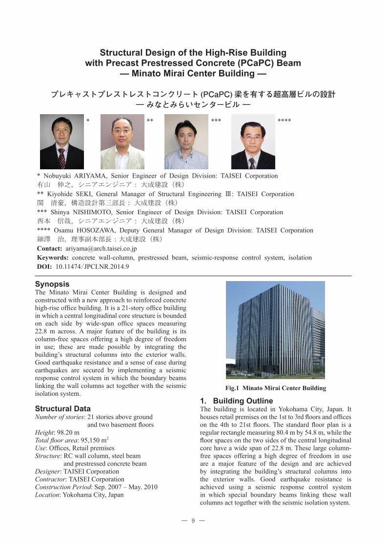
1. Building OutlineThe building is located in Yokohama City, Japan. It houses retail premises on the 1st to 3rd floors and offices on the 4th to 21st floors. The standard floor plan is a regular rectangle measuring 80.4 m by 54.8 m, while the floor spaces on the two sides of the central longitudinal core have a wide span of 22.8 m. These large column-free spaces offering a high degree of freedom in use are a major feature of the design and are achieved by integrating the building’s structural columns into the exterior walls. Good earthquake resistance is achieved using a seismic response control system in which special boundary beams linking these wall columns act together with the seismic isolation system.
Fig.1 Minato Mirai Center Building

― ―10
2. Outline of structural systemA seismic isolation system is adopted in order to reduce the seismic response of the superstructure and ensure continuing functionality of the building even after a major earthquake. This isolation system consists of rubber bearings and elastic sliding bearings under the
1st floor.A reinforced concrete (RC) structure was chosen for the superstructure of the building so as to take advantage of its superior cost performance as compared with a steel(S) structure and ensure a comfortable interior space.
Fig.2 Standard floor plan
N
ELVホ
ール
低層
バン
ク
PS
PS
EPS
EPS
EPS
EPS
EPS
EPS
EPS
EPS
EPS
EPS
EPS
EPS
EPS
EPS
EPS
EPS
EPS
廊下廊下
PS
PS
4F・6F8F・10F12F
5F・7F9F・11F
4F・6F8F・10F12F
5F・7F9F・11F
MR
MR
MR
EPS
EPS
M R
MR
MR
MR
EPS
EPS
ボイド
A
女子便所男子便所
ボイ
ドB
SK
女子
便所
男子
便所
SK
EPS
EPS
EPS
EPS
リフレッシュコーナー(禁煙)
身障者用
便所
湯沸・
ゴミ置場
アラーム弁室
アラーム弁室
湯沸リフレッシュ
コーナー
(喫煙)
階段A
階段B
ゴミ
置場
バルコニーA
バルコニーB
PS
PS
特別避難階段附室兼用非常用ELV乗降ロビーB
非常用ELV17人乗り10 5m/min
非常用ELV17人乗り105m/ min
DS
DS
20人乗り180m/ min
20人乗り180m/ min
20人乗り180m/ min
20人乗り180m/ min
20人乗り180m/ min
20人乗り180m/ min
20人乗り180m/ min
20人乗り180m/ min
80400
54800
22800 228009200
Fig.3 Structural floor plan
Seismic Frame Horizontal loads supported by structural frames at the core and periphery
Vertical Load Supporting Member
PCaPC beams (H=1,000 mm) spaced 3.2 m apart in the wide-span sections Connected to the wall column with pin joint
Fig.4 Structural outline
PCaPC Beam Elastic beams Restoring force is secured for the entire building.
Seismic response control beams
Seismic isolation
Rubber bearing + Elastic sliding bearing
Wall columns Wall columns also act as exterior finishing material 400-500 mm thick x 1,400 mm wide Fc36 – 90(N/mm2)
Low-yield-point steel (LY100) is used for the web reinforcement at the center of the beams.
Rigid frames with shear walls
Low-rise section

― ―11
To obtain wide-span floors, prestressed concrete beams built by precast method (PCaPC beams) are adopted to support vertical loads only. These beams, spanning the distance between the peripheral and core wall columns, are pin-jointed so as to avoid exerting out-of-plane bending moment on the wall columns. Lateral loading during earthquakes acts on the structural frame, consisting of peripheral and core wall columns with steel beam linkages. Low-yield-point steel (yield strength = 100 N/mm2) is for the web of the steel beam linkages so as to ensure shear yielding and absorb seismic energy in earthquakes. The wall columns with 400-500 mm in thickness are achieved by controlling the loads that act on them; they are precasted and form the exterior finish of the building. Good earthquake resistance and a sense of ease during earthquakes are secured by reducing the response shear force and response acceleration at every floor by implementing a seismic response control system in combination with the seismic isolation system. Elastic steel beams are installed on the 17th and higher floors to secure sufficient restoring force for the entire building and to reduce residual deformation after an earthquake.
3. Seismic DesignThe target performance levels for earthquake resistance are defined as listed in Table-1 under the design earthquake motions for small/moderate and major seismic events.To gain a full understanding of the earthquake-resistant performance of the building, a nonlinear dynamic response analysis was carried out using the design earthquake motions.
4. Adoption of PCaPC Beams(1) Design of PCaPC BeamsThe PCaPC beams are adopted for this building so as to make possible large column-free office spaces. The PCaPC beams are arranged as simply supported beams in the transverse direction (with a span of 22.8 m) between the peripheral and core wall columns. Fig.5 outlines the PCaPC beam design. The beams are spaced 3.2 m apart. From the viewpoint of transportation and lifting of precast members, the central 16.5 m long section of the 22.8 m span consists of two PCaPC beams placed in parallel, while the end sections are of cast-in-place concrete. The beams are 1,000 mm depth. In the central precast section of the PCaPC beams, there are through holes of diameter 400 mm spaced 1,200 mm apart.As a structural solution to minimize the cross-sectional dimensions of the PCaPC beam, a study was made into the use of high-strength materials and the application of high levels of prestressing force. As a result, a cross section measuring 580 mm width (290 mm width x 2 beams in parallel) by 1,000 mm depth is realized, using concrete with a specified design strength of 80 N/mm2 and high-strength reinforcement (USD685A, yield strength = 685 N/mm2) as prestressing tendons. In conventional prestressed concrete beams using prestressing steel as tendons, there is a limit to how much the cross-sectional dimensions of the beams can be reduced due to the existence of the longitudinal reinforcement apart from tendons and the need to secure adequate spacing between tendons. In contrast, a feature of this method is that extra tendons in the axial direction are eliminated by the use of high-strength reinforcement in the axial direction that act as main
Table-1 Target earthquake-resistant performanceLevel of earthquake motion Level 1 earthquake motion
Small or moderate seismic eventLevel 2 earthquake motions
Major seismic event
Superstructure Stress induced in structural member: not higher than the allowable stress
Stress induced in structural member: within elastic limit
Story deformation angle: not more than 1/200
Story deformation angle: not more than 1/100
Accumulated damage of seismic response control member: not more than 0.2
Seismic isolation system Rubber bearing: Rubber bearing:
• Pull-out force should not be induced in the bearing.
• Compression stress: within compression limit stress
• Tension stress: within tension limit stress of 1.0 N/mm2
Sliding bearing: Sliding bearing:
• Sliding deformation: not more than 500 mm
• Sliding deformation: not more than 500 mm
• Bearing should not lift. • Bearing should not lift.
Substructure Stress induced in structural member: not exceeds the allowable stress
Stress induced in structural member: not exceeds the allowable stress
Footing beams and mat slabPiles
Stress induced in structural member: not exceeds the allowable stress
Stress induced in structural member: not exceed the design strength

― ―12
概 要 本建物は地上21階建の超高層オフィスビルであり,センターコアの両側に22.8m のロングスパンの執務空間
を有している。本建物の特徴は,外壁を構造体の壁柱として利用し,柱型のない自由度の高い空間を確保して
いることである。ロングスパン部に採用した PCaPC 梁には高強度コンクリートと高強度鉄筋を使用し,断面
を最小化するとともに,優れた経済性も確保している。また壁柱同士をつなぐ境界梁を利用した制振構造と ,免震構造を組み合わせることにより,高い耐震性能と地震時の居住性・安心感を確保しており,RC 造による
超高層オフィスの新しい試みを示す建物である。
reinforcement and tendons, so tensioning force can be introduced in the lowermost area of the beams.
(2) Pin Joint of PCaPC BeamsTo prevent excessive out-of-plane bending moment acting on the thin wall columns that support the PCaPC beams, structural details were developed with the aim
Fig.6 Pin joint of PCaPC beam
μQ
Q
M=μQe
Wall-Column
e
End of Beam
of realizing a pin joint for the ends of the beam. A full-scale test of the pin joint (Fig. 6) was conducted to confi rm its shear strength and rotational performance. The test results confi rmed that the degree of fi xation of the pin joint at the end of the beam was decreased very much compared with that of a rigid joint. Further, the shear strength of the bracket at the end was shown to have a margin of safety three times greater than the design vertical load due to gravity.
5. ConclusionThe Minato Mirai Center Building incorporates a new type of seismic response control system in which the structural members that absorb seismic energy are completely separated from the structural members bearing the permanent vertical load. This seismic response control system operates in combination with a seismic isolation system, making it possible to secure good earthquake-resistant performance and, at the same time, achieve an open architectural design. Further, the building makes use of a prefabrication method using PCaPC beams with high strength material. The result is an offi ce building of superior quality, constructed with good cost-performance in a reasonable construction time.
Fig.5 Outline of PCaPC beam
X
22800
1FL
100
165003150
PCaPs梁
X
3150
700 1650 1200 1200 1200 1200 1200 1200 1200 1200 1200 1200 1200 1650 700
17900
φ400x12
PCa工法在来工法 Fc48<Fc60>
550(570)
ロ 部 12000イ 部 2250 イ 部 2250機械式継手
定着筋
在来工法 Fc48<Fc60>
Total length 22,800mm
Cast-in-place section 3,150mm
Precast (PCa) section 16,500mm
Cast-in-place section 3,150mm
Top reinforcement : 4-D32 (1st) SD390 + 4-D38 (2nd) SD390 Bottom reinforcement : 4-D38 (1st) USD685A + 4-D38 (2nd) USD685A Stirrup: 2xD13-□-@200
1.Concrete Specified design strength: Fc = 80 N/mm2
Strength when prestressing force is introduced: Fc = 60 N/mm2 2.Tendon Steel bar: USD685A, prestressing force: 2,620 kN (σs = 575 N/mm2)
X
1000
290 290
スラブコンクリート(Fc30)Slab concrete (Fc30)