structural design and detailing cvp 441web.iitd.ac.in/~sbhalla/c.pdf · model in staad and analyze...
TRANSCRIPT
STRUCTURAL DESIGN AND DETAILING
CVP 441INTERACTIVE
SESSION ON STEEL ANALSYSIS AND
DESIGN EXERCISE
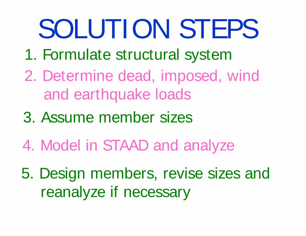
SOLUTION STEPS:M1. Formulate structural system2. Determine dead, imposed, wind
and earthquake loads3. Assume member sizes4. Model in STAAD and analyze5. Design members, revise sizes and
reanalyze if necessary
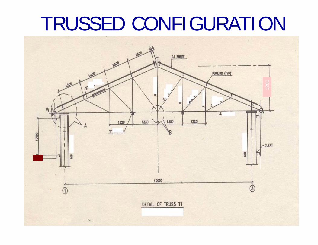
1800
TRUSSED CONFIGURATION
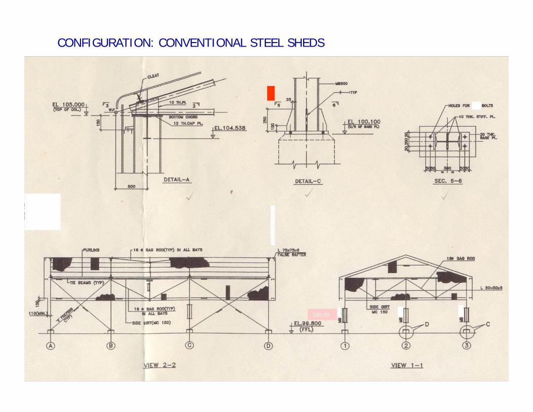
100.00
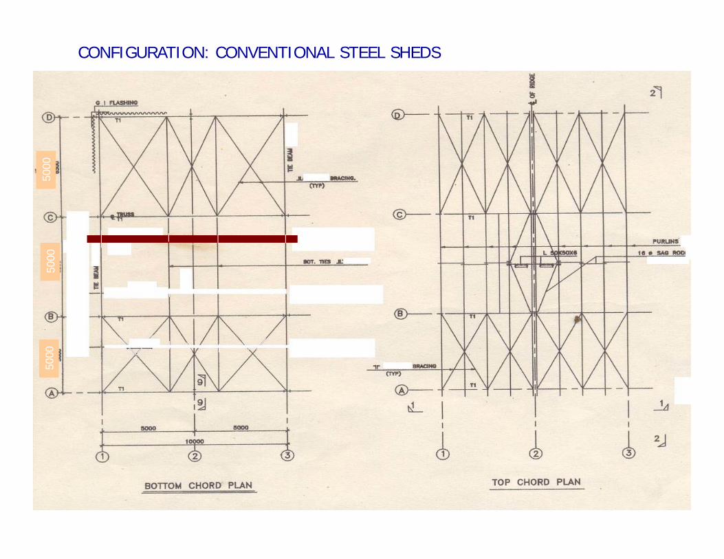
CONFIGURATION: CONVENTIONAL STEEL SHEDS
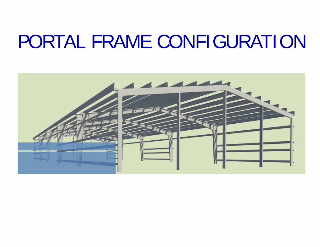
PORTAL FRAME CONFIGURATION
5000
5000
5000
CONFIGURATION: CONVENTIONAL STEEL SHEDS
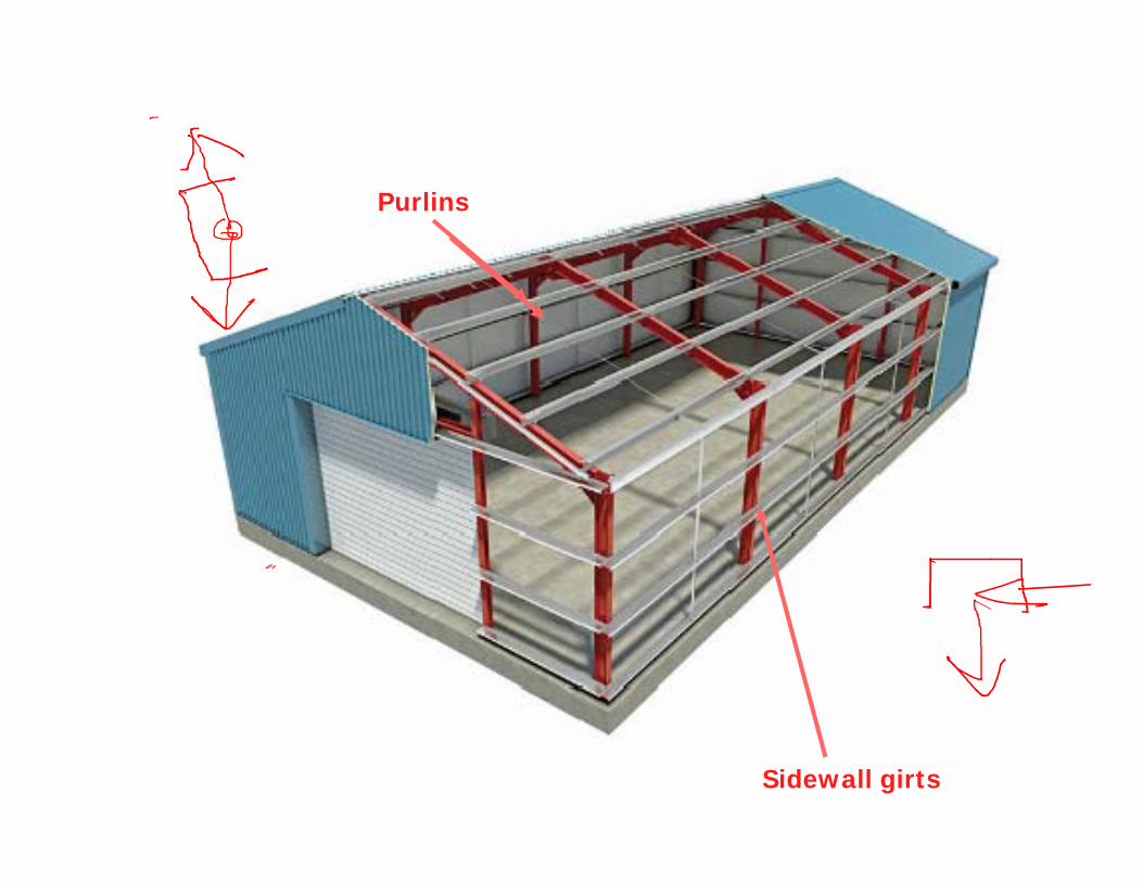
Purlins
Sidewall girts
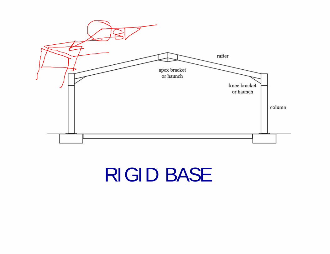
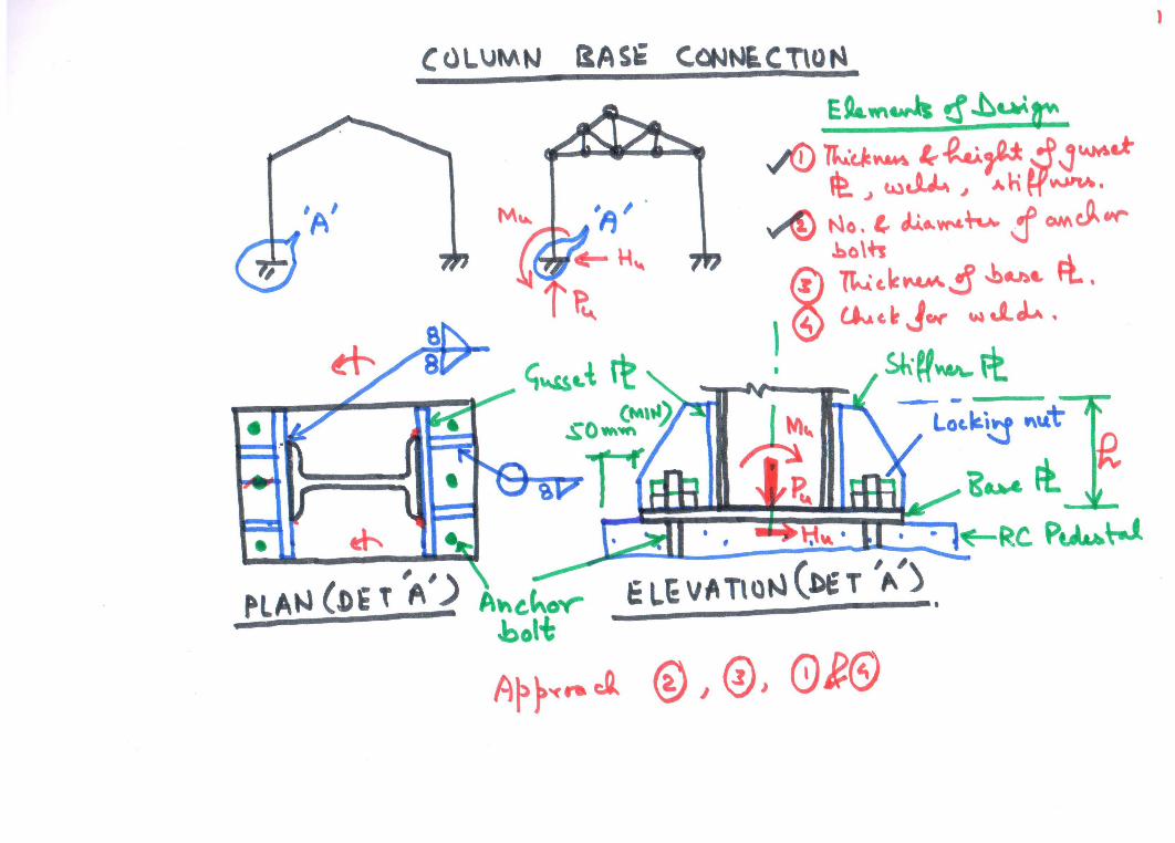
RIGID BASE
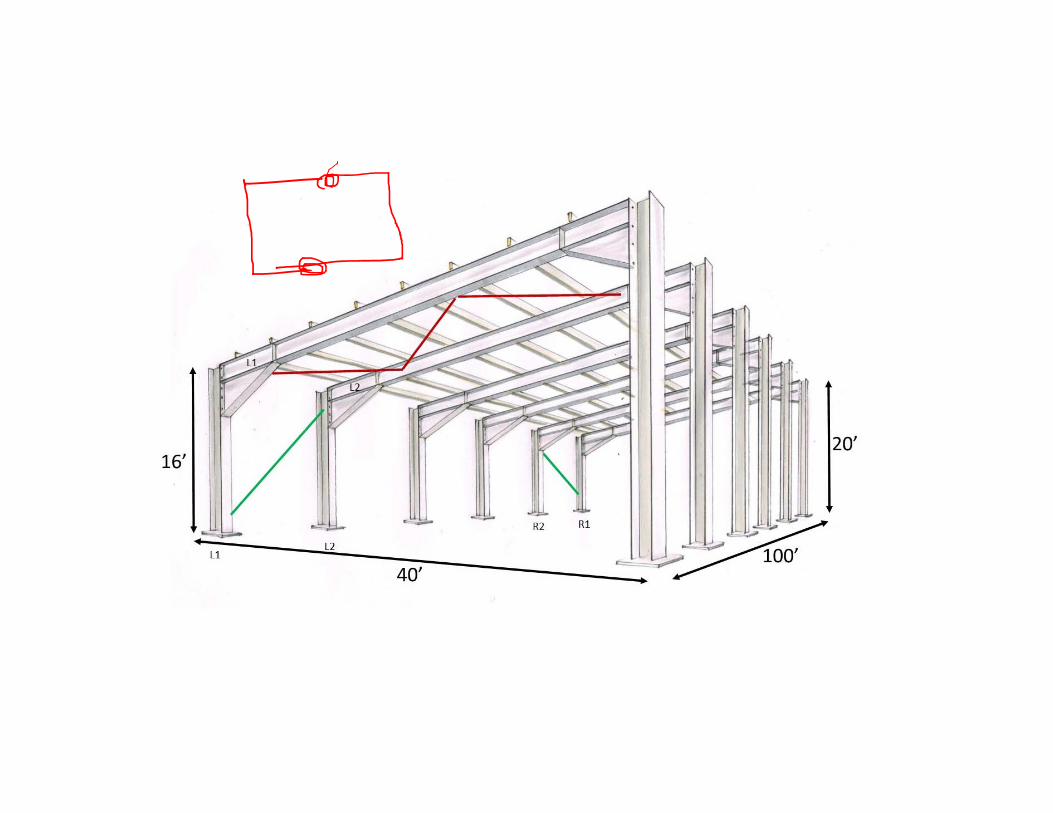
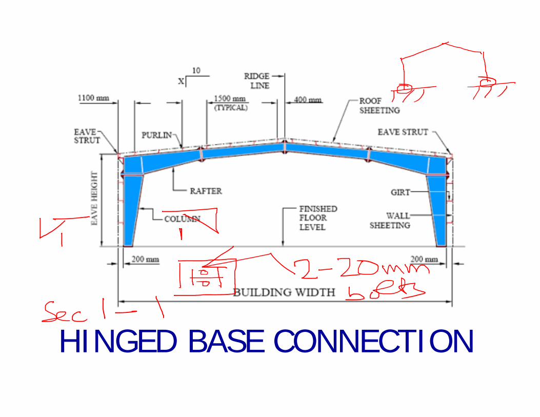
HINGED BASE CONNECTION


10/23/2017 1
FOUNDATIONS
SHALLOW DEEP
Depth to width ratio, D/B <= 1 Moderately deep: 1 < D/B <= 15Deep: D/B > 15
Load transfer through direct soil pressure Load transfer through skin friction and end reaction
Construction: Excavate, construct, cover, compact (small disturbance)
Driving or boring + casting (Large disturbance)
10/23/2017 2
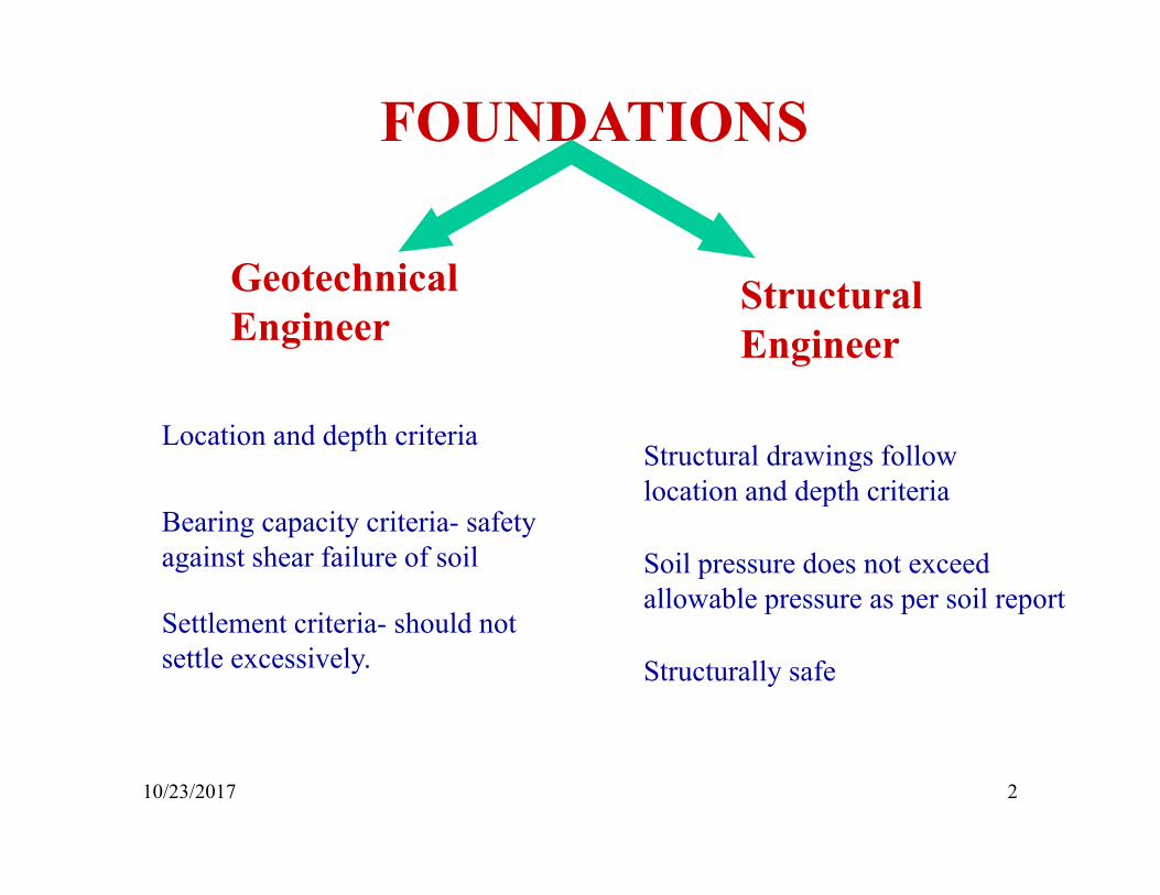
FOUNDATIONS
Geotechnical Engineer
Structural Engineer
Location and depth criteria
Bearing capacity criteria- safety against shear failure of soil
Settlement criteria- should not settle excessively.
Structural drawings follow location and depth criteria
Soil pressure does not exceed allowable pressure as per soil report
Structurally safe
10/23/2017 3
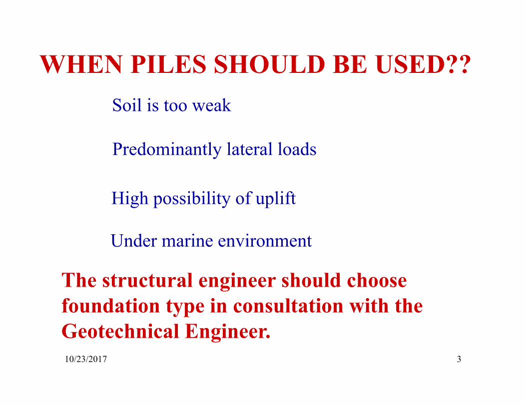
WHEN PILES SHOULD BE USED??Soil is too weak
Predominantly lateral loads
High possibility of uplift
Under marine environment
The structural engineer should choose foundation type in consultation with the Geotechnical Engineer.
10/23/2017 4
INPUTS FROM SOIL REPORT
Pile type, diameter and length
Load capacity in compression
Load capacity in uplift
Lateral load capacity
In addition, good Geotechnical Engineers generally provide pile reinforcement. Otherwise, they should provide details of lateral load analysis.
10/23/2017 5
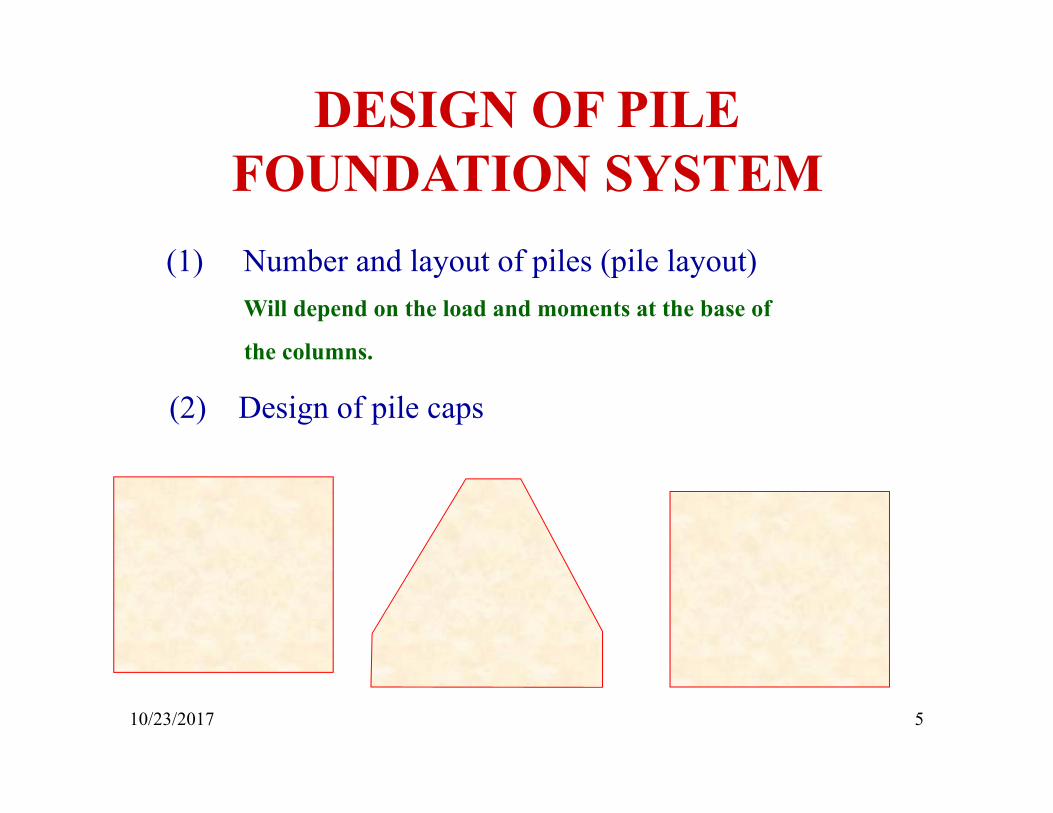
DESIGN OF PILE FOUNDATION SYSTEM
(1) Number and layout of piles (pile layout)Will depend on the load and moments at the base of
the columns.
(2) Design of pile caps
10/23/2017 6
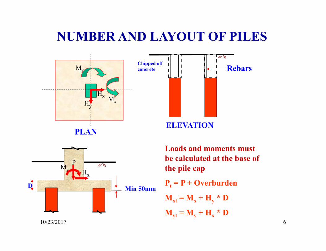
NUMBER AND LAYOUT OF PILES
PLANELEVATION
Chipped off concreteMy
Mx
Min 50mm
HxHy
Loads and moments must be calculated at the base of the pile cap
Pt = P + Overburden
Mxt = Mx + Hy * D
Myt = My + Hx * D
PMy Hx
D
Rebars
10/23/2017 7
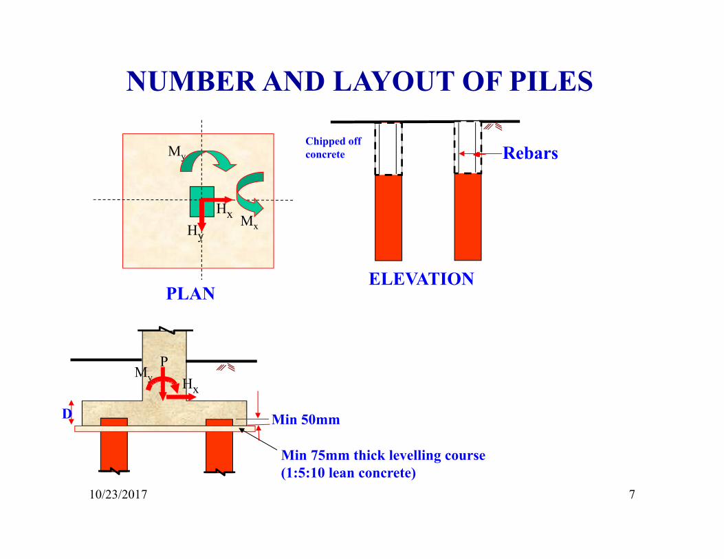
NUMBER AND LAYOUT OF PILES
PMy Hx
PLANELEVATION
RebarsChipped off concreteMy
Mx
Min 75mm thick levelling course (1:5:10 lean concrete)
HxHy
D Min 50mm
10/23/2017 8
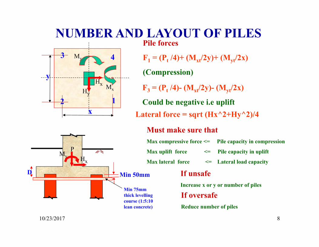
NUMBER AND LAYOUT OF PILES
PMy Hx
My
Mx
Min 75mm thick levelling course (1:5:10 lean concrete)
HxHy
Pile forces
F1 = (Pt /4)+ (Mxt/2y)+ (Myt/2x)
(Compression)
D Min 50mm
12
3 4
x
yF3 = (Pt /4)- (Mxt/2y)- (Myt/2x)
Could be negative i.e uplift
Must make sure thatMax compressive force <= Pile capacity in compression
Max uplift force <= Pile capacity in uplift
Max lateral force <= Lateral load capacity
If unsafeIncrease x or y or number of piles
If oversafeReduce number of piles
Lateral force = sqrt (Hx^2+Hy^2)/4
10/23/2017 9
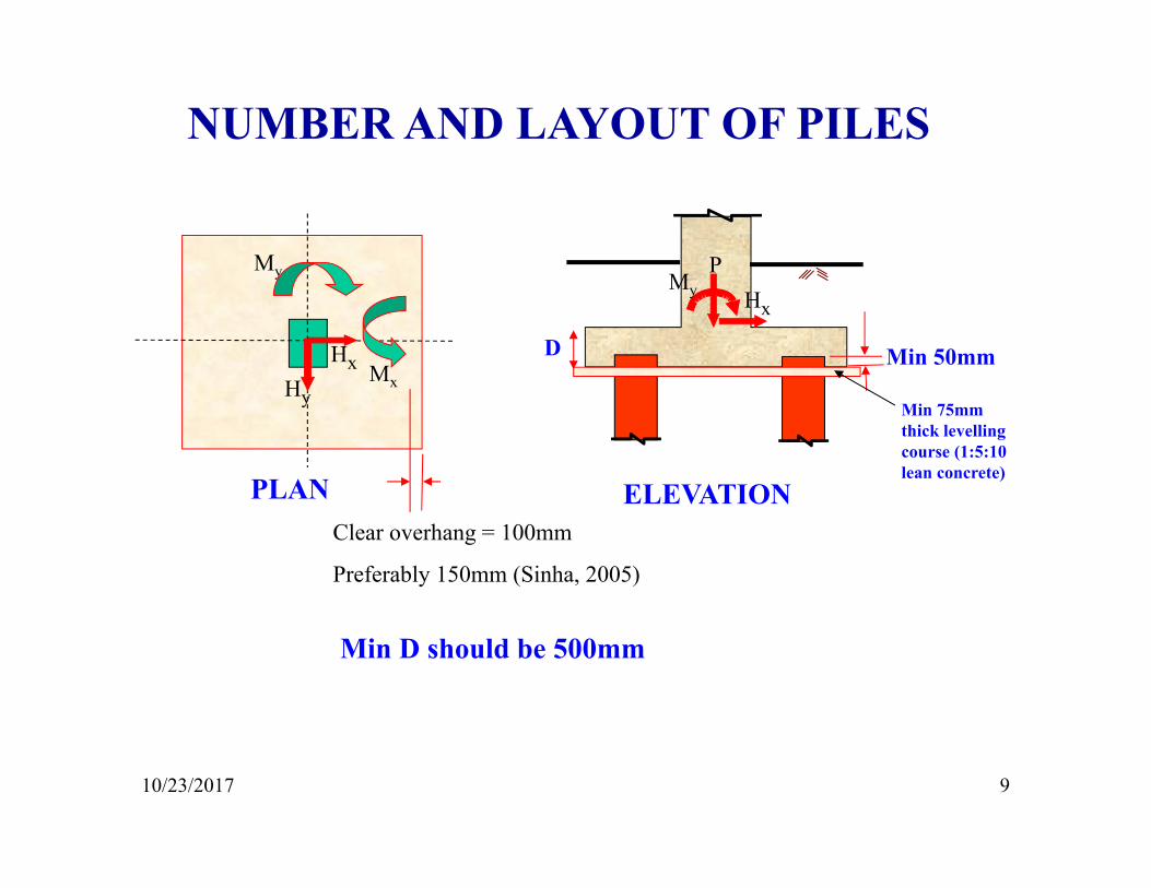
NUMBER AND LAYOUT OF PILES
PMy Hx
PLAN
My
Mx
Min 75mm thick levelling course (1:5:10 lean concrete)
HxHy
D Min 50mm
ELEVATIONClear overhang = 100mm
Preferably 150mm (Sinha, 2005)
Min D should be 500mm
10/23/2017 10
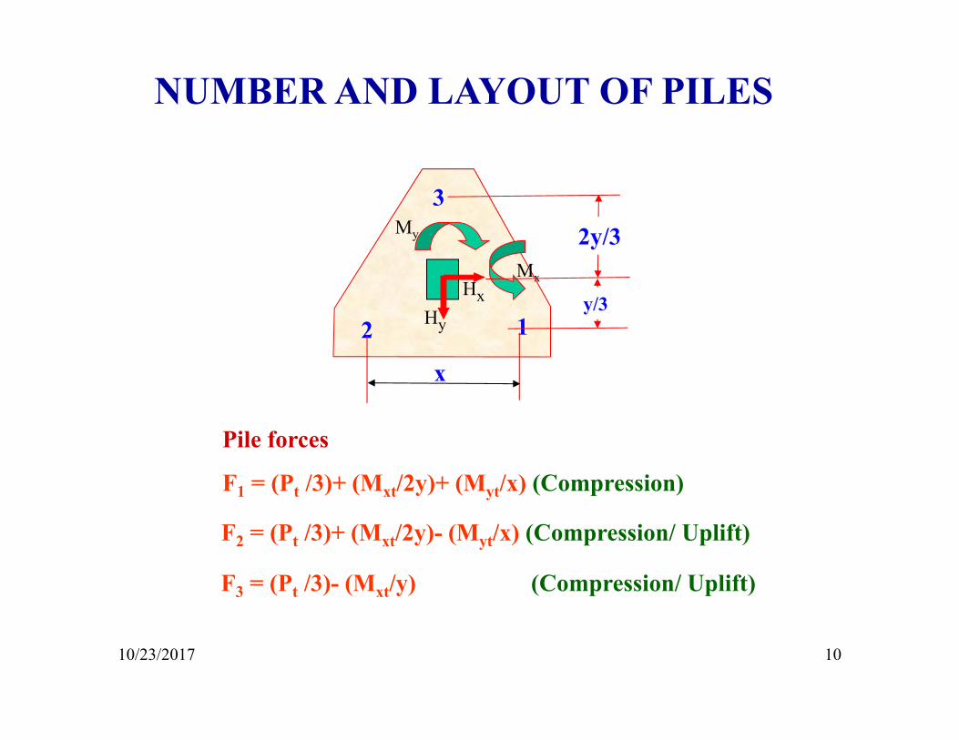
NUMBER AND LAYOUT OF PILES
My
MxHx
Hy 12
x
32y/3
y/3
Pile forces
F1 = (Pt /3)+ (Mxt/2y)+ (Myt/x) (Compression)
F2 = (Pt /3)+ (Mxt/2y)- (Myt/x) (Compression/ Uplift)
F3 = (Pt /3)- (Mxt/y) (Compression/ Uplift)
10/23/2017 11
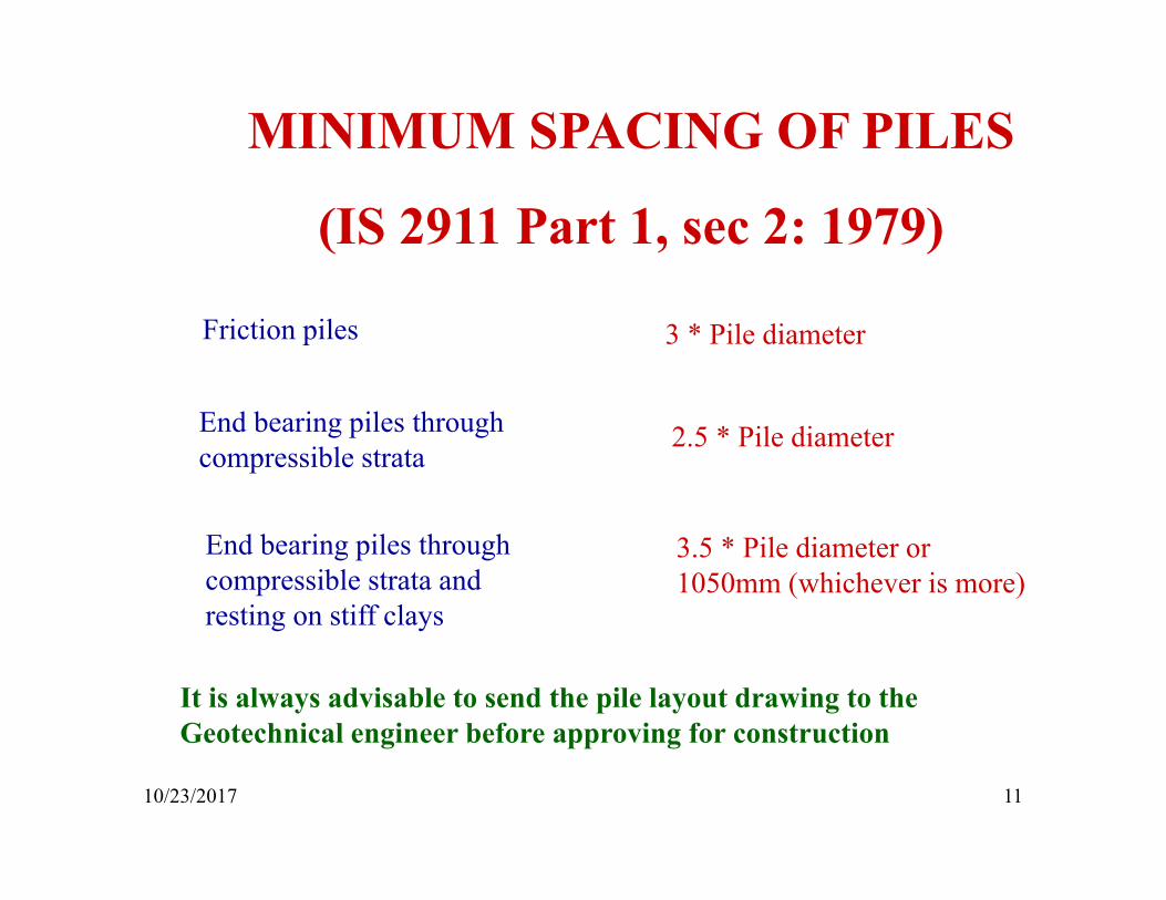
MINIMUM SPACING OF PILES
(IS 2911 Part 1, sec 2: 1979)
Friction piles
End bearing piles through compressible strata
3 * Pile diameter
2.5 * Pile diameter
End bearing piles through compressible strata and resting on stiff clays
3.5 * Pile diameter or 1050mm (whichever is more)
It is always advisable to send the pile layout drawing to the Geotechnical engineer before approving for construction
10/23/2017 12
STRUCTURAL DESIGN
OF PILE CAPS
Design for bending
Check for one-way shear
Check for two-way/ punching shear
10/23/2017 13
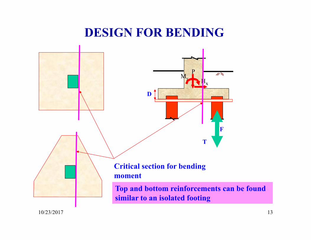
PMy Hx
D
DESIGN FOR BENDING
Critical section for bending moment
F
T
Top and bottom reinforcements can be found similar to an isolated footing
10/23/2017 14
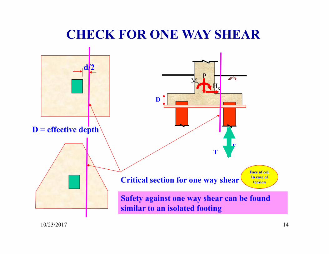
PMy Hx
D
CHECK FOR ONE WAY SHEAR
Critical section for one way shear
Safety against one way shear can be found similar to an isolated footing
d/2
D = effective depth
FT
Face of col. In case of tension
10/23/2017 15
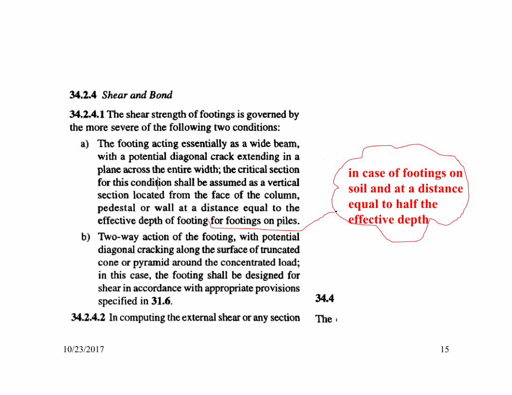
in case of footings on soil and at a distance equal to half the effective depth
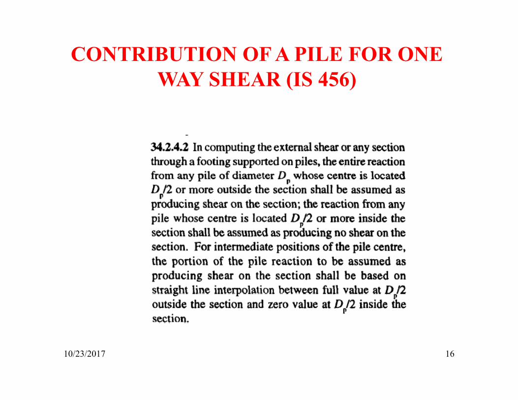
10/23/2017 16
CONTRIBUTION OF A PILE FOR ONE WAY SHEAR (IS 456)
10/23/2017 17
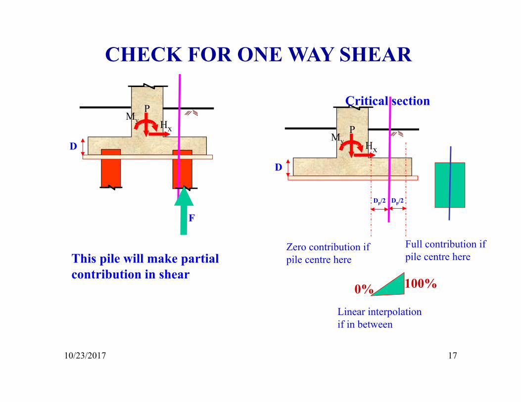
CHECK FOR ONE WAY SHEAR
PMy Hx
D
F
This pile will make partial contribution in shear
PMy Hx
D
Dp/2 Dp/2
Full contribution if pile centre here
Zero contribution if pile centre here
Critical section
0% 100%
Linear interpolation if in between
10/23/2017 18
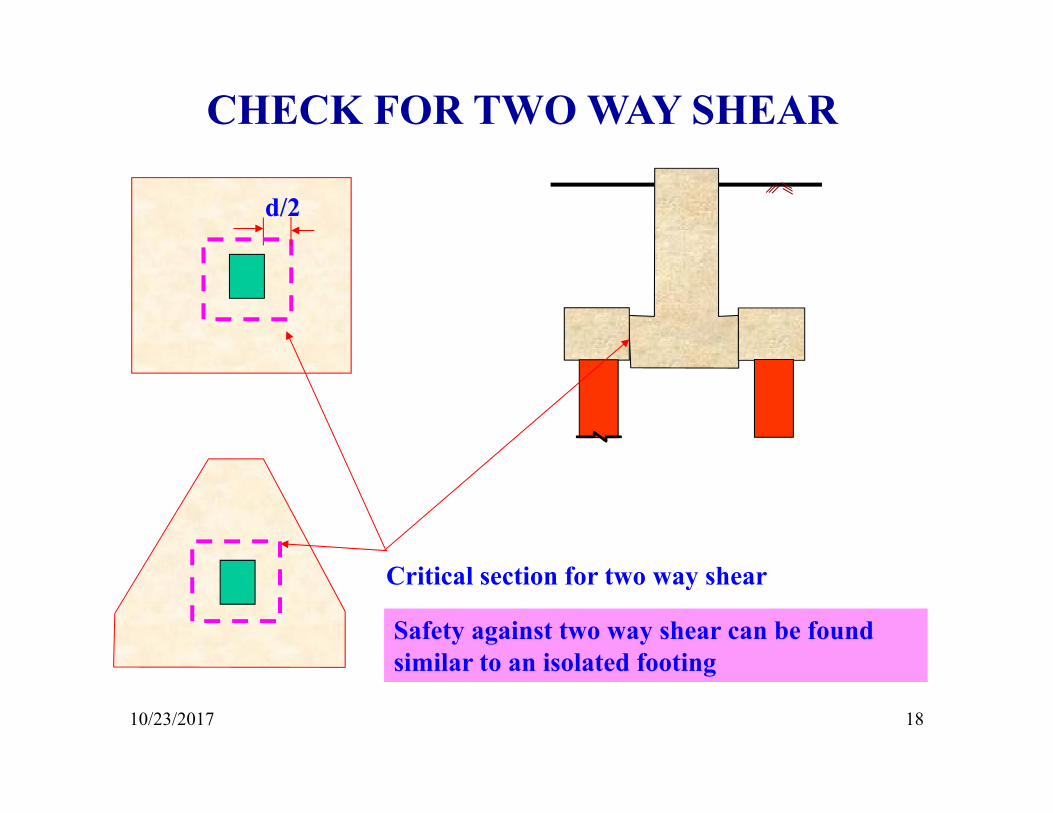
CHECK FOR TWO WAY SHEAR
Critical section for two way shear
Safety against two way shear can be found similar to an isolated footing
d/2
P
10/23/2017 19
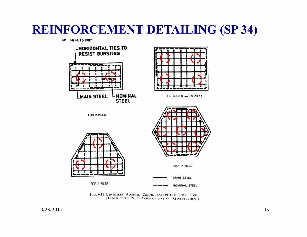
REINFORCEMENT DETAILING (SP 34)
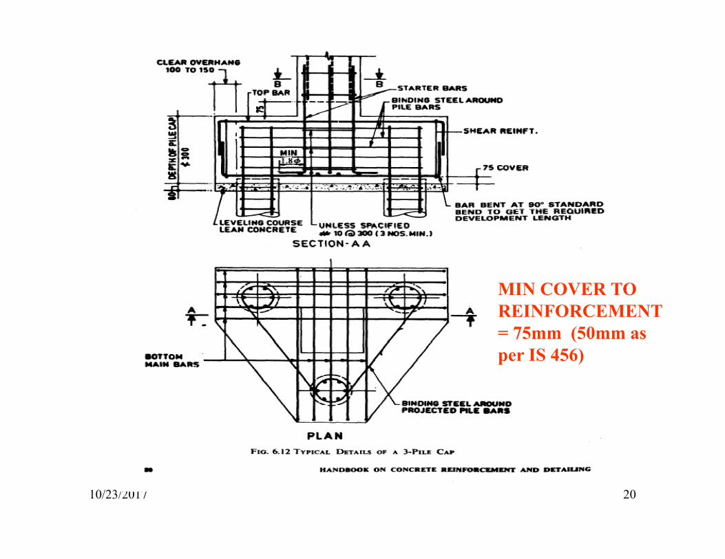
10/23/2017 20
MIN COVER TO REINFORCEMENT = 75mm (50mm as per IS 456)

10/23/2017 21
THANK YOU