structural analysis - emucivil.emu.edu.tr/courses/civl211/lecture-9.pdf · roof-supporting truss...
TRANSCRIPT
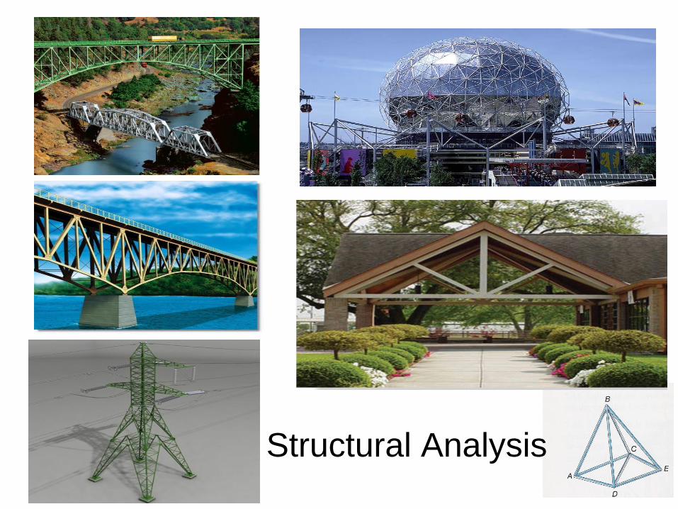
Structural Analysis
Chapter Objectives
• To show how to determine the forces in the
members of a truss using:
the method of joints and
the method of sections.
Chapter Outline
• Two-force members
• Planar (Simple) Trusses
• The Method of Joints
• Zero-Force Members
• The Method of Sections
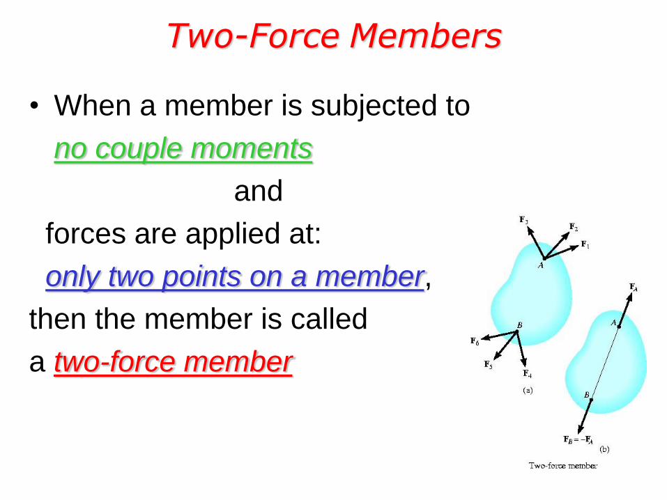
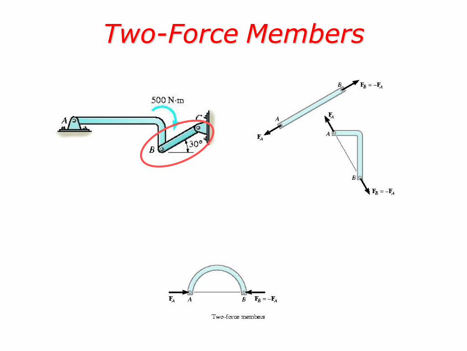
Two-Force Members
• When a member is subjected to
no couple moments
and
forces are applied at:
only two points on a member,
then the member is called
a two-force member
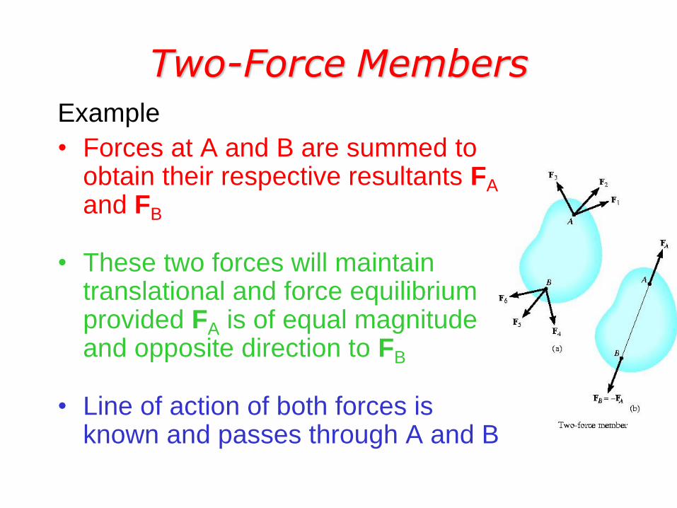
Two-Force Members Example
• Forces at A and B are summed to obtain their respective resultants FA and FB
• These two forces will maintain translational and force equilibrium provided FA is of equal magnitude and opposite direction to FB
• Line of action of both forces is known and passes through A and B
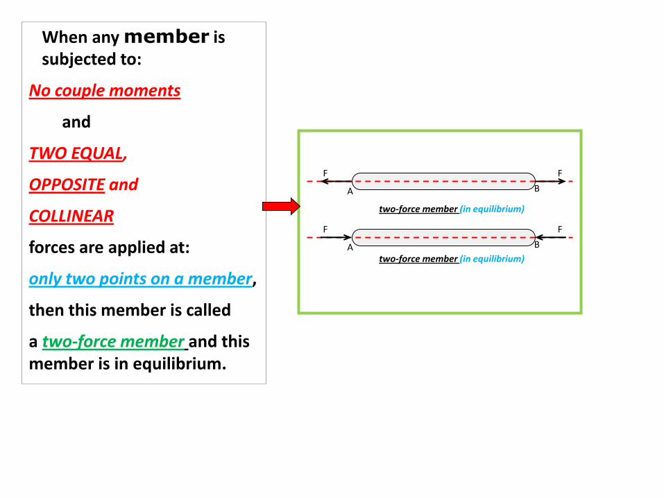
When any member is subjected to:
No couple moments
and
TWO EQUAL,
OPPOSITE and
COLLINEAR
forces are applied at:
only two points on a member,
then this member is called
a two-force member and this member is in equilibrium.
A B
F F
A B
F F
two-force member (in equilibrium)
two-force member (in equilibrium)
A B
F
F
NOT a two-force member (NOT in EQUILIBRIUM)
A B
F F
M0
A B
F
F
A B
F
F
A B M0
M0
A B
F F
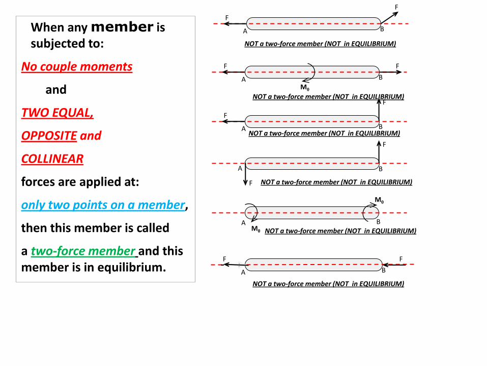
When any member is subjected to:
No couple moments
and
TWO EQUAL,
OPPOSITE and
COLLINEAR
forces are applied at:
only two points on a member,
then this member is called
a two-force member and this member is in equilibrium.
NOT a two-force member (NOT in EQUILIBRIUM)
NOT a two-force member (NOT in EQUILIBRIUM)
NOT a two-force member (NOT in EQUILIBRIUM)
NOT a two-force member (NOT in EQUILIBRIUM)
NOT a two-force member (NOT in EQUILIBRIUM)
Two-Force Members
PLANAR Trusses
OR
2-D Trusses
SIMPLE Trusses
OR
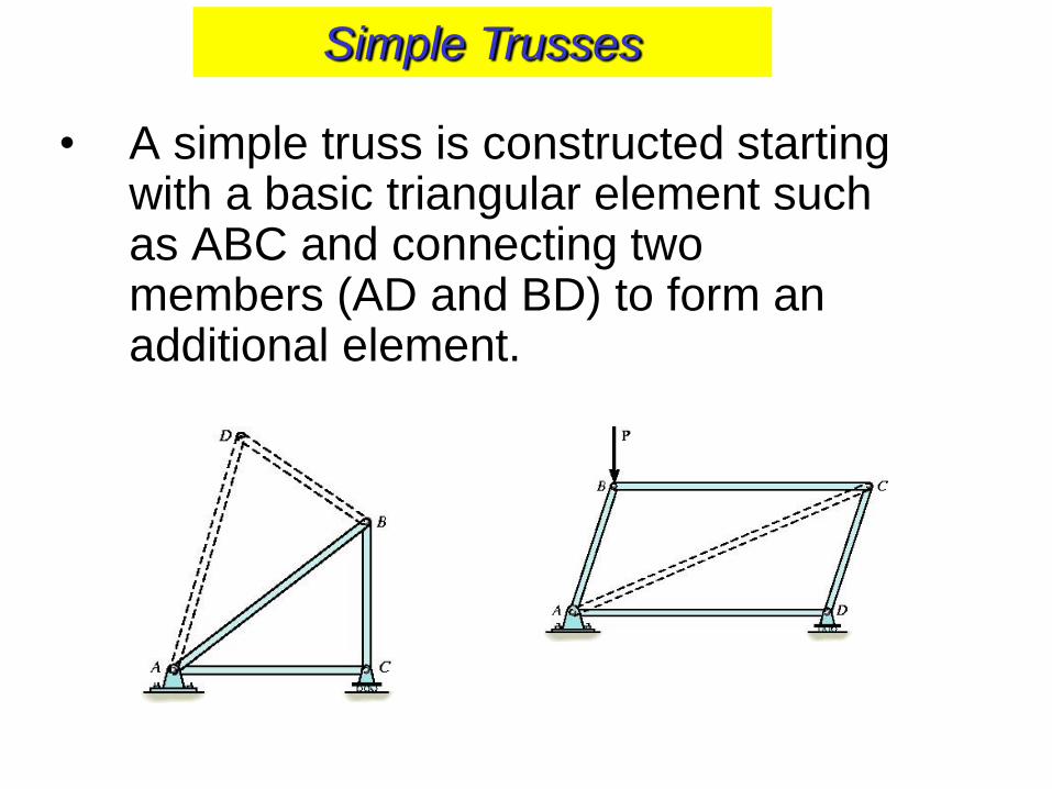
• A simple truss is constructed starting with a basic triangular element such as ABC and connecting two members (AD and BD) to form an additional element.
Simple Trusses
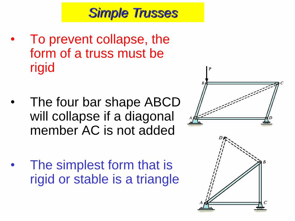
• To prevent collapse, the form of a truss must be rigid
• The four bar shape ABCD will collapse if a diagonal member AC is not added
• The simplest form that is rigid or stable is a triangle
Simple Trusses
ALL the truss members,
• member-end forces and
• applied forces are in one plane (2D),
(in the same plane).
That is why it is called PLANAR or 2-D
TRUSSES.
Simple Trusses
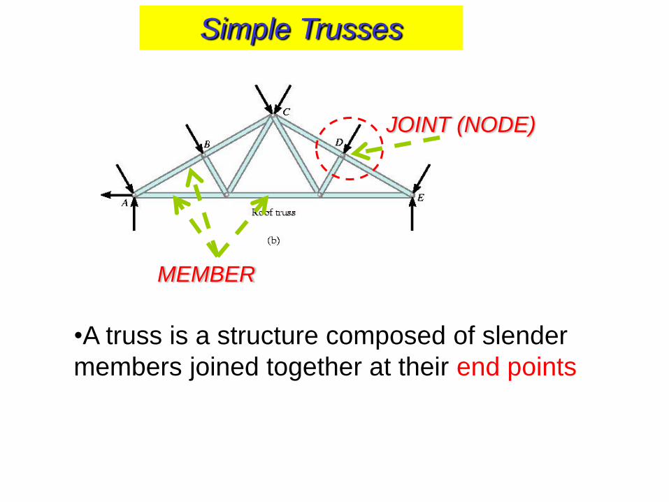
•A truss is a structure composed of slender
members joined together at their end points
JOINT (NODE)
MEMBER
Simple Trusses
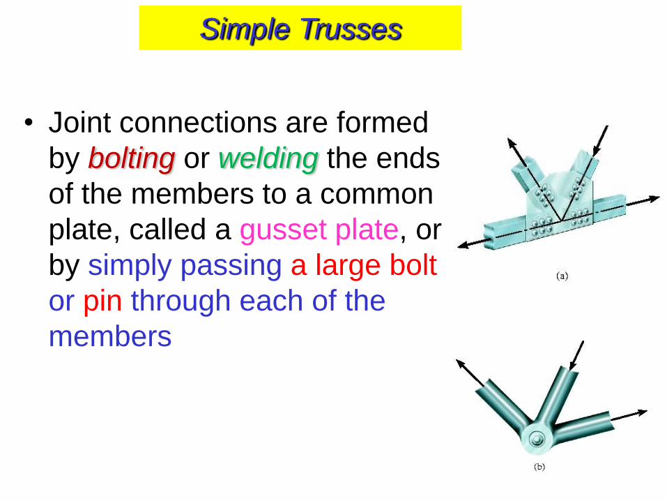
• Joint connections are formed
by bolting or welding the ends
of the members to a common
plate, called a gusset plate, or
by simply passing a large bolt
or pin through each of the
members
Simple Trusses
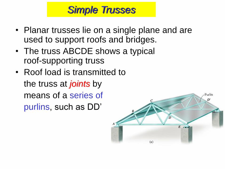
• Planar trusses lie on a single plane and are used to support roofs and bridges.
• The truss ABCDE shows a typical roof-supporting truss
• Roof load is transmitted to
the truss at joints by
means of a series of
purlins, such as DD’
Simple Trusses
Simple Trusses
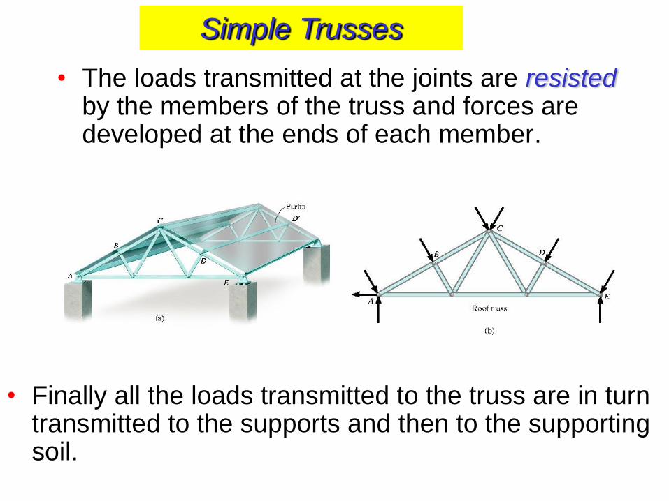
• The loads transmitted at the joints are resisted by the members of the truss and forces are developed at the ends of each member.
• Finally all the loads transmitted to the truss are in turn transmitted to the supports and then to the supporting soil.
Simple Trusses
Simple Trusses
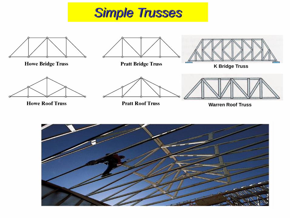
K Bridge Truss
Warren Roof Truss
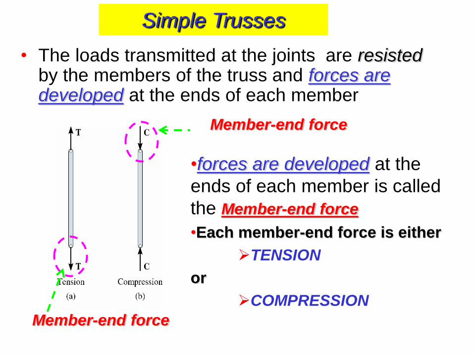
• The loads transmitted at the joints are resisted by the members of the truss and forces are developed at the ends of each member
Member-end force
Member-end force
•forces are developed at the
ends of each member is called
the Member-end force
•Each member-end force is either
TENSION
or
COMPRESSION
Simple Trusses
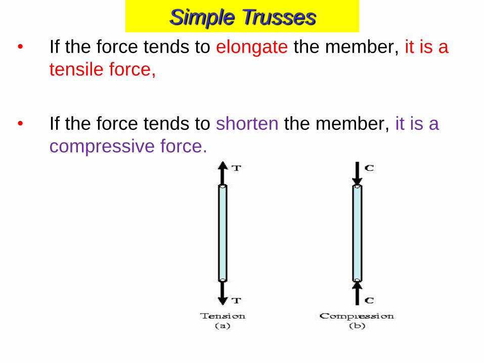
• If the force tends to elongate the member, it is a
tensile force,
• If the force tends to shorten the member, it is a
compressive force.
Simple Trusses
Each member is in equilibrium under the action of
only two forces that are:
- equal in magnitude,
- opposite in direction and
- collinear.
Therefore truss members are called:
TWO-FORCE MEMBERS
Simple Trusses
• Analysis of Planar Trusses means:
Find ALL the member-end forces
developed in each member,
Find the reactions at the supports
Simple Trusses
Assumptions for Analysis and Design
1. “All loadings are applied at the joints”
• Assumption is true for most of the applications of bridge and roof trusses
• Weight of the members are neglected since the forces supported by the members are large in comparison
• If member’s weight is considered, apply it as a vertical force, by giving half of the magnitude to each end of the member.
Simple Trusses
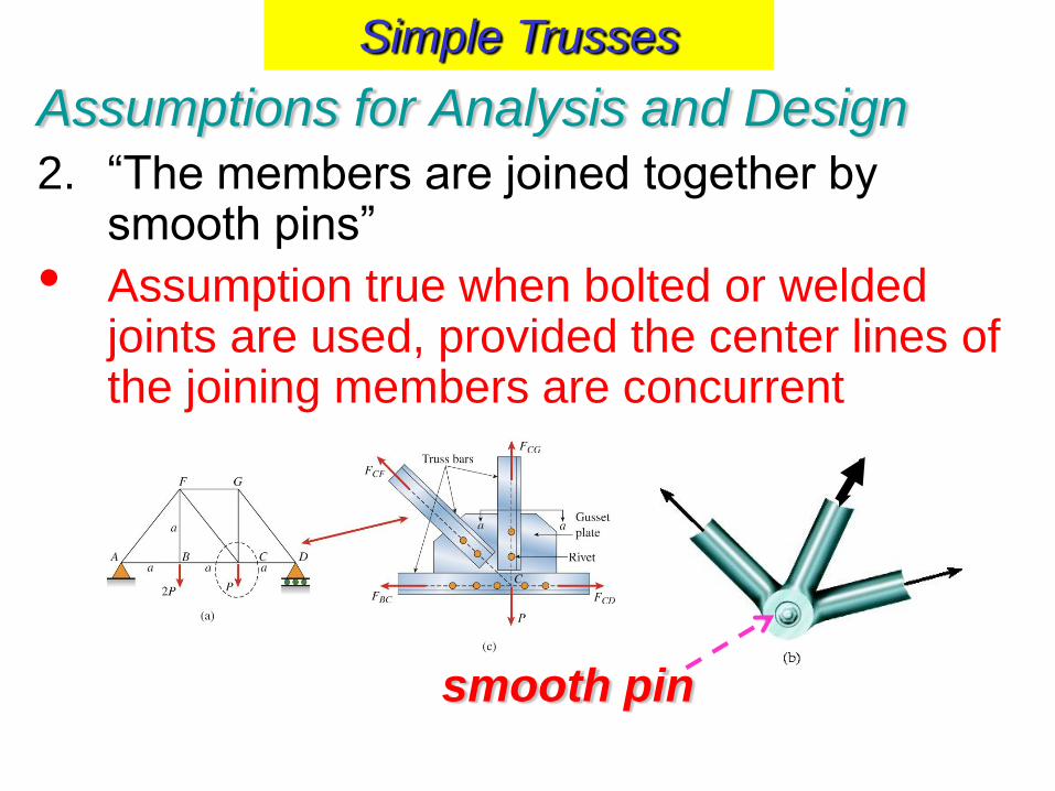
Assumptions for Analysis and Design
2. “The members are joined together by smooth pins”
• Assumption true when bolted or welded joints are used, provided the center lines of the joining members are concurrent
smooth pin
Simple Trusses
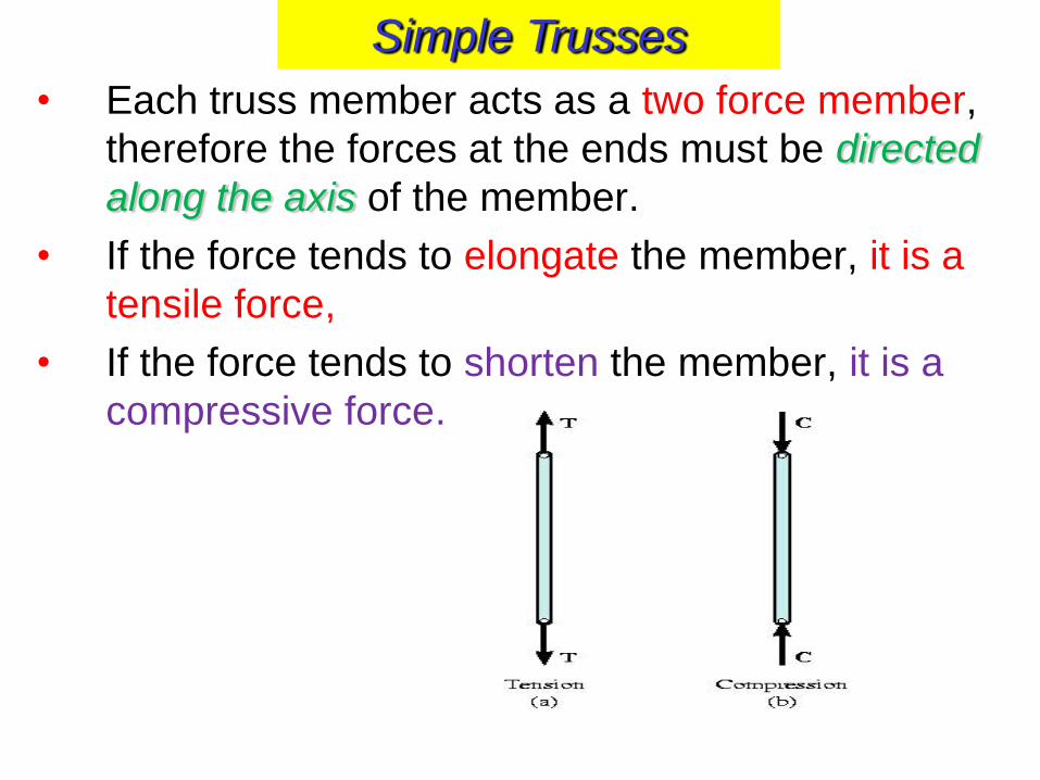
• Each truss member acts as a two force member,
therefore the forces at the ends must be directed
along the axis of the member.
• If the force tends to elongate the member, it is a
tensile force,
• If the force tends to shorten the member, it is a
compressive force.
Simple Trusses
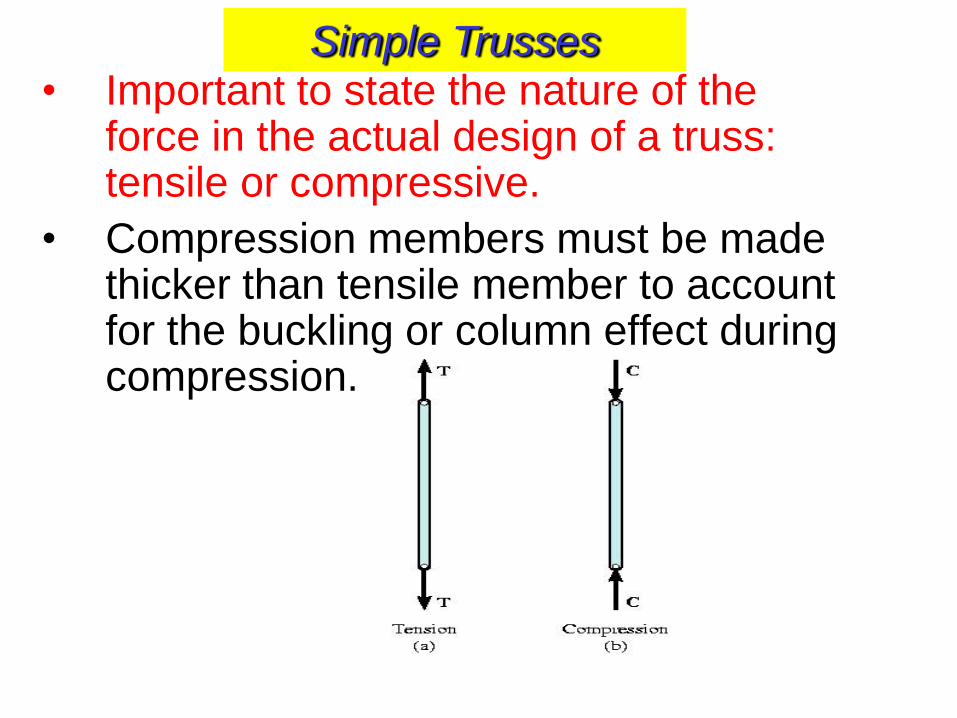
• Important to state the nature of the force in the actual design of a truss: tensile or compressive.
• Compression members must be made thicker than tensile member to account for the buckling or column effect during compression.
Simple Trusses
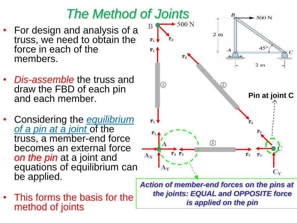
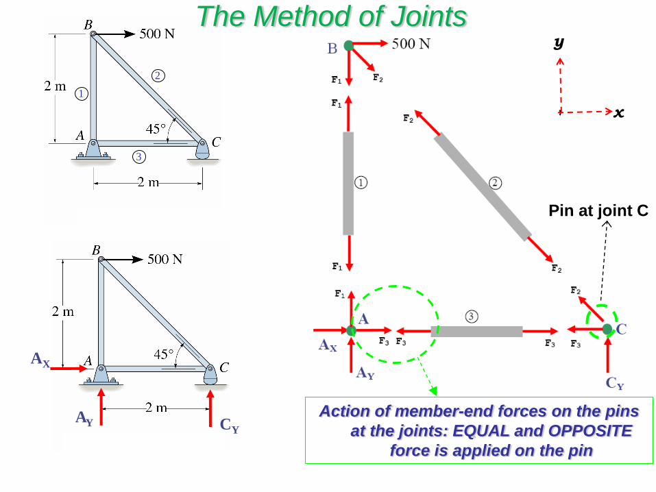
Action of member-end forces on the pins at
the joints: EQUAL and OPPOSITE force
is applied on the pin
Pin at joint C
The Method of Joints • For design and analysis of a
truss, we need to obtain the force in each of the members.
• Dis-assemble the truss and draw the FBD of each pin and each member.
• Considering the equilibrium of a pin at a joint of the truss, a member-end force becomes an external force on the pin at a joint and equations of equilibrium can be applied.
• This forms the basis for the method of joints
2
3
1
AY
AX
CY Action of member-end forces on the pins
at the joints: EQUAL and OPPOSITE
force is applied on the pin
Pin at joint C
y
x
The Method of Joints
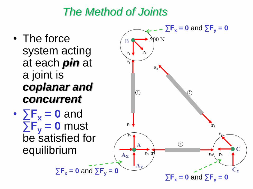
• The force system acting at each pin at a joint is coplanar and concurrent
• ∑Fx = 0 and ∑Fy = 0 must be satisfied for equilibrium
∑Fx = 0 and ∑Fy = 0
∑Fx = 0 and ∑Fy = 0 ∑Fx = 0 and ∑Fy = 0
The Method of Joints
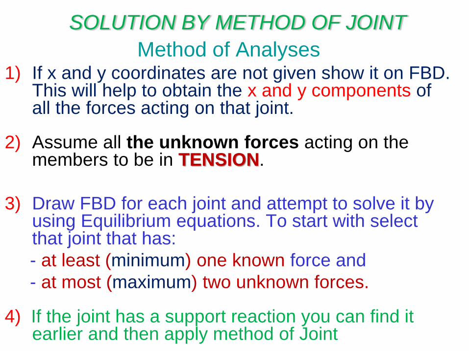
Method of Analyses 1) If x and y coordinates are not given show it on FBD.
This will help to obtain the x and y components of all the forces acting on that joint.
2) Assume all the unknown forces acting on the members to be in TENSION.
3) Draw FBD for each joint and attempt to solve it by using Equilibrium equations. To start with select that joint that has:
- at least (minimum) one known force and
- at most (maximum) two unknown forces.
4) If the joint has a support reaction you can find it earlier and then apply method of Joint
SOLUTION BY METHOD OF JOINT
Method of Analyses
5) Apply equilibrium equations ∑Fx = 0 and ∑Fy = 0
6) Solve the unknown forces based on that joints FBD.
7) APPLY THE SAME METHODOLOGY FOR THE REST OF THE JOINTS.
SOLUTION METHOD OF JOINT
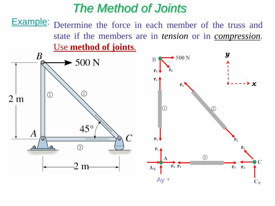
Example:
1 2
3
Determine the force in each member of the truss and
state if the members are in tension or in compression.
Use method of joints. y
x
The Method of Joints
Ay
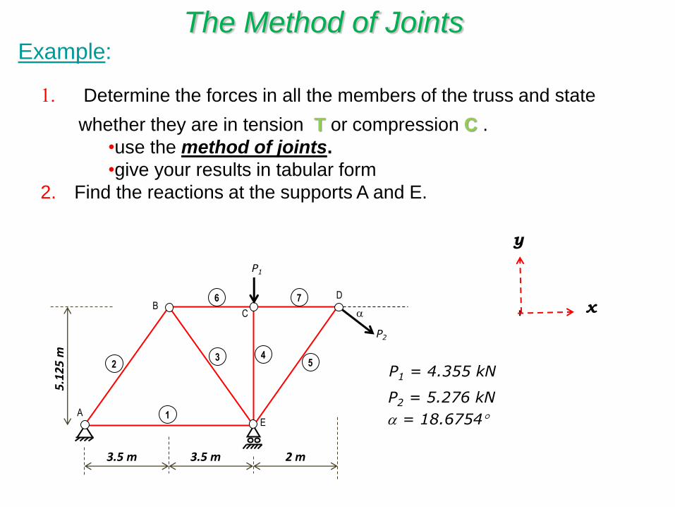
1. Determine the forces in all the members of the truss and state
whether they are in tension T or compression C .
•use the method of joints.
•give your results in tabular form
2. Find the reactions at the supports A and E.
Example:
y
x
P2
P1 = 4.355 kN
P2 = 5.276 kN
= 18.6754
D
P1
2 m 3.5 m 3.5 m
5.1
25
m
1
2 3 4
5
6 7
A
B C
E
The Method of Joints
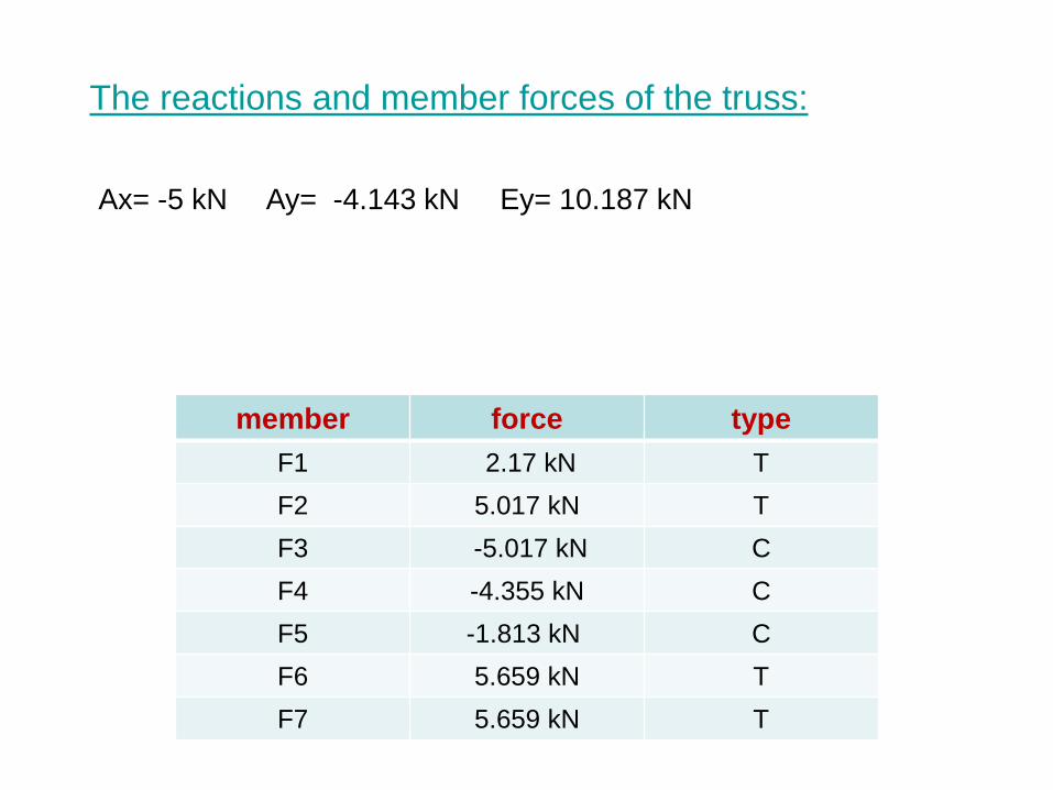
The reactions and member forces of the truss:
type force member
T 2.17 kN F1
T 5.017 kN F2
C -5.017 kN F3
C -4.355 kN F4
C -1.813 kN F5
T 5.659 kN F6
T 5.659 kN F7
Ax= -5 kN Ay= -4.143 kN Ey= 10.187 kN
Example:
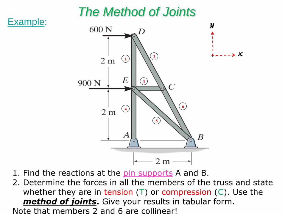
1. Find the reactions at the pin supports A and B. 2. Determine the forces in all the members of the truss and state
whether they are in tension (T) or compression (C). Use the method of joints. Give your results in tabular form.
Note that members 2 and 6 are collinear!
1 2
4
3
6
5
y
x
The Method of Joints
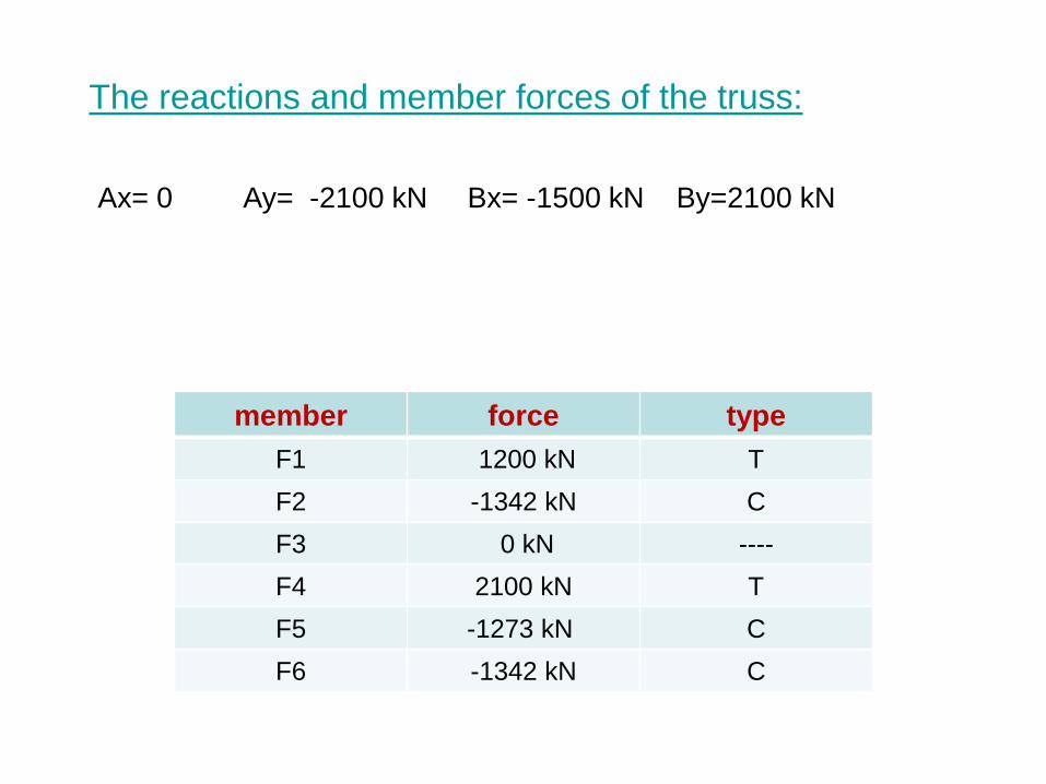
The reactions and member forces of the truss:
type force member
T 1200 kN F1
C -1342 kN F2
---- 0 kN F3
T 2100 kN F4
C -1273 kN F5
C -1342 kN F6
Ax= 0 Ay= -2100 kN Bx= -1500 kN By=2100 kN
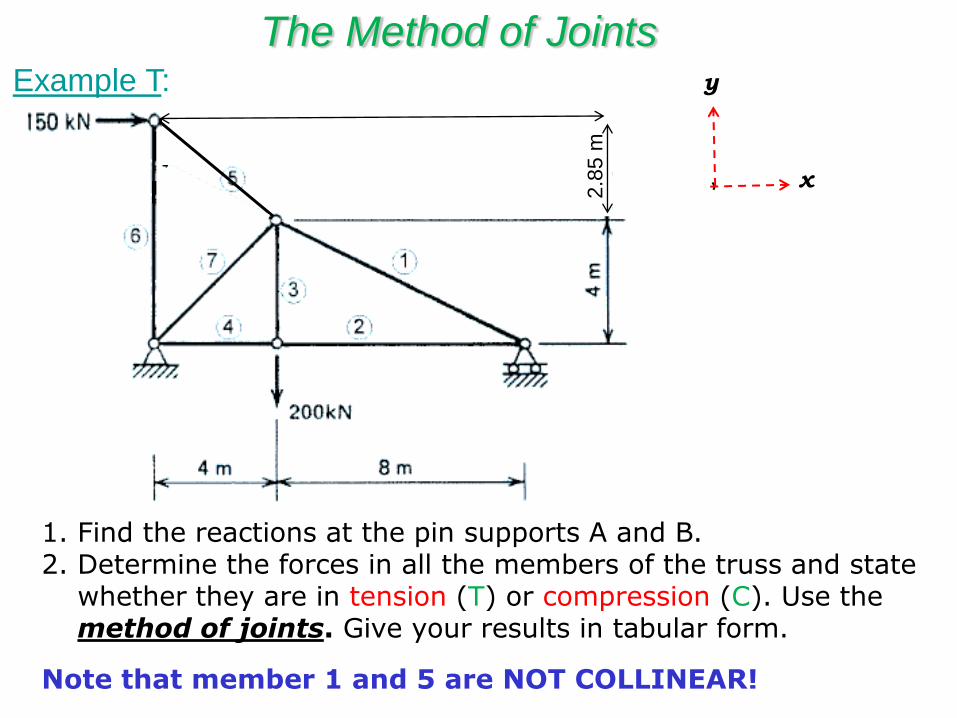
1. Find the reactions at the pin supports A and B. 2. Determine the forces in all the members of the truss and state
whether they are in tension (T) or compression (C). Use the method of joints. Give your results in tabular form.
Note that member 1 and 5 are NOT COLLINEAR!
y
x
The Method of Joints
2.8
5 m
Example T:
Example: The Method of Joints
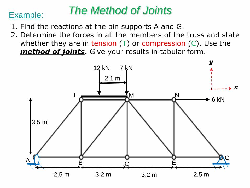
1. Find the reactions at the pin supports A and G. 2. Determine the forces in all the members of the truss and state
whether they are in tension (T) or compression (C). Use the method of joints. Give your results in tabular form.
12 kN 7 kN
2.5 m 3.2 m 3.2 m 2.5 m
3.5 m
2.1 m
A B C E G
L M N 6 kN
y
x
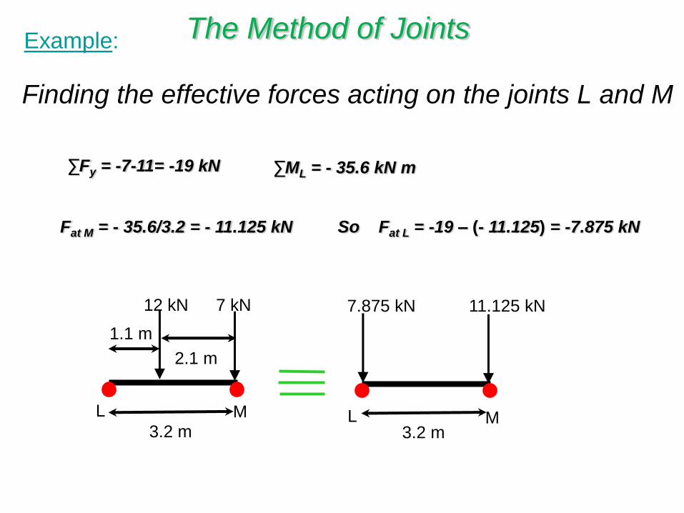
Example: The Method of Joints
Finding the effective forces acting on the joints L and M
12 kN 7 kN
1.1 m
3.2 m
7.875 kN 11.125 kN
3.2 m
L L M M
2.1 m
∑Fy = -7-11= -19 kN ∑ML = - 35.6 kN m
Fat M = - 35.6/3.2 = - 11.125 kN So Fat L = -19 – (- 11.125) = -7.875 kN
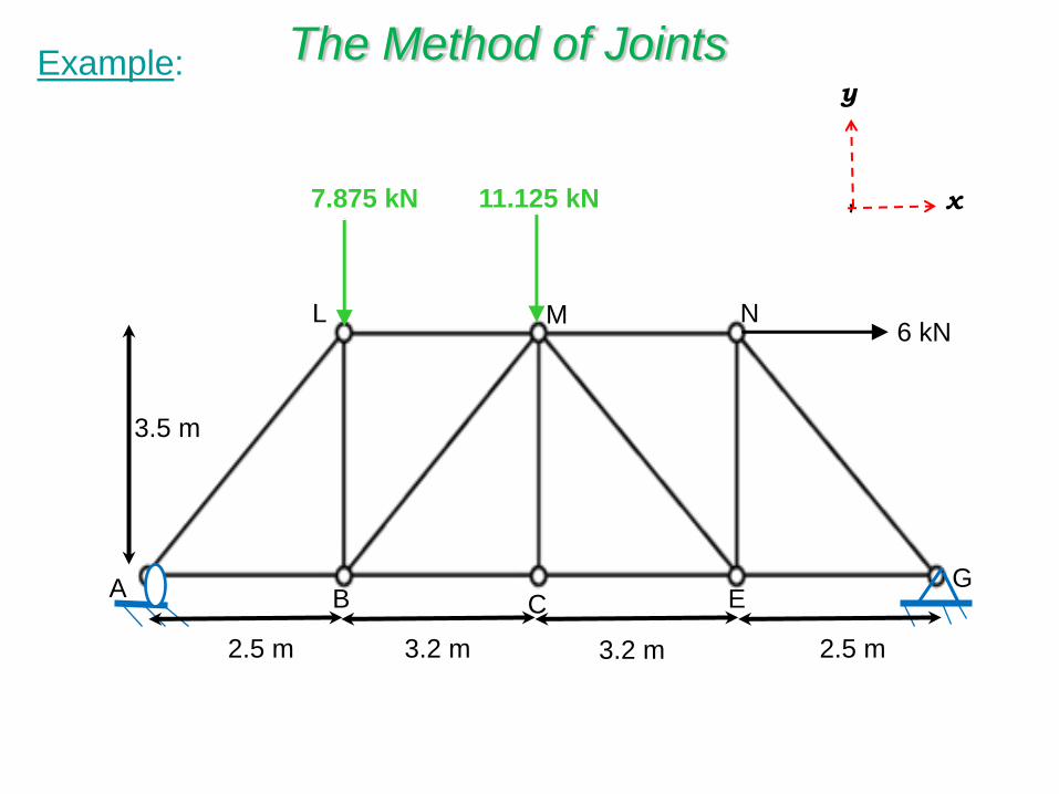
Example: The Method of Joints y
x
11.125 kN
2.5 m 3.2 m 3.2 m 2.5 m
3.5 m
A B C E G
L M N 6 kN
7.875 kN
27.5°
51.6°
11.2 kN
46 kN
8.5 kN
1.85 m
1.60 m 0.75 m
1.6
0 m
2
.10
m
C D
A
B E F
1 2
3
4 5
6
7
8
9
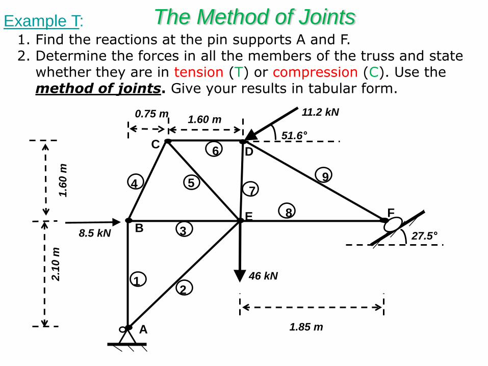
1. Find the reactions at the pin supports A and F. 2. Determine the forces in all the members of the truss and state
whether they are in tension (T) or compression (C). Use the method of joints. Give your results in tabular form.
Example T: The Method of Joints
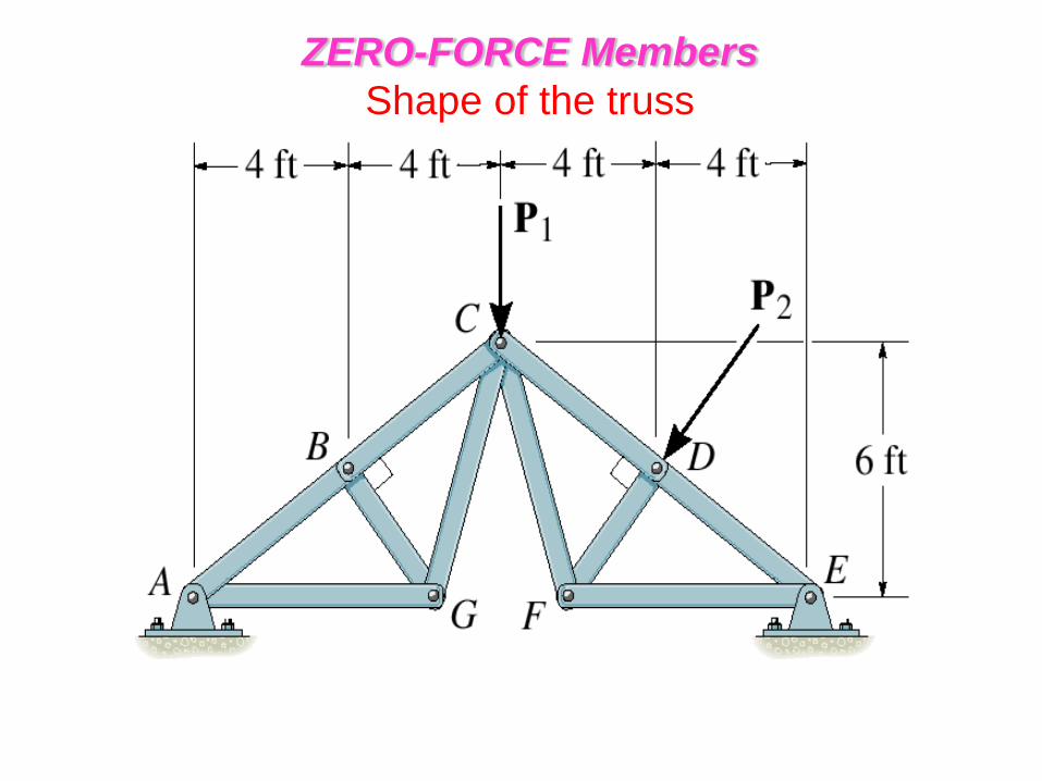
ZERO-FORCE Members
• Method of joints is simplified when the members which support no loading are determined.
Within a truss, zero-force member exists due to:
• Shape of the member connections
• Support reaction types.
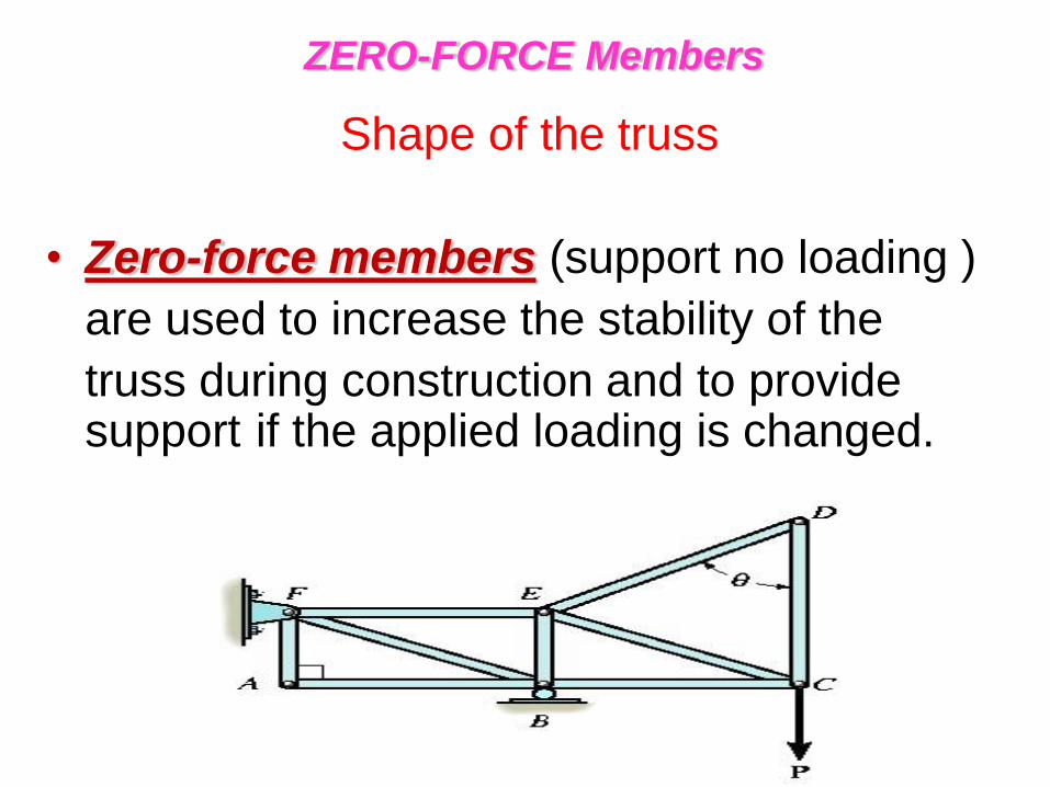
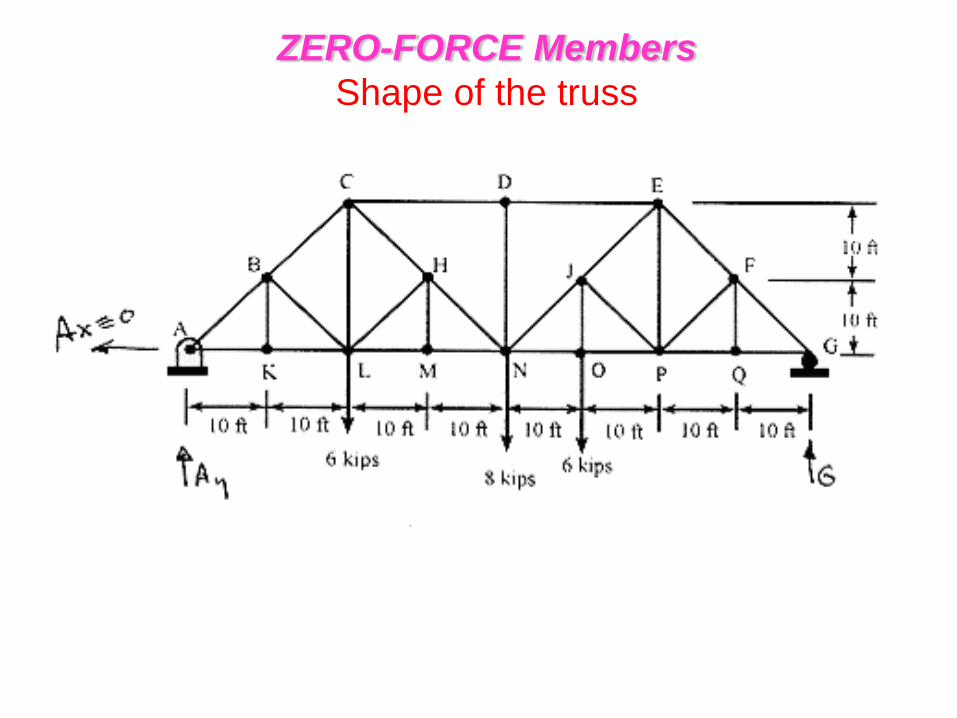
ZERO-FORCE Members
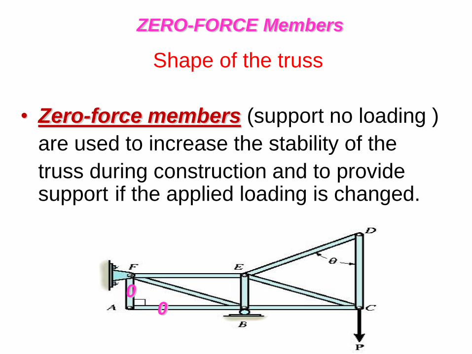
Shape of the truss
• Zero-force members (support no loading )
are used to increase the stability of the
truss during construction and to provide support if the applied loading is changed.
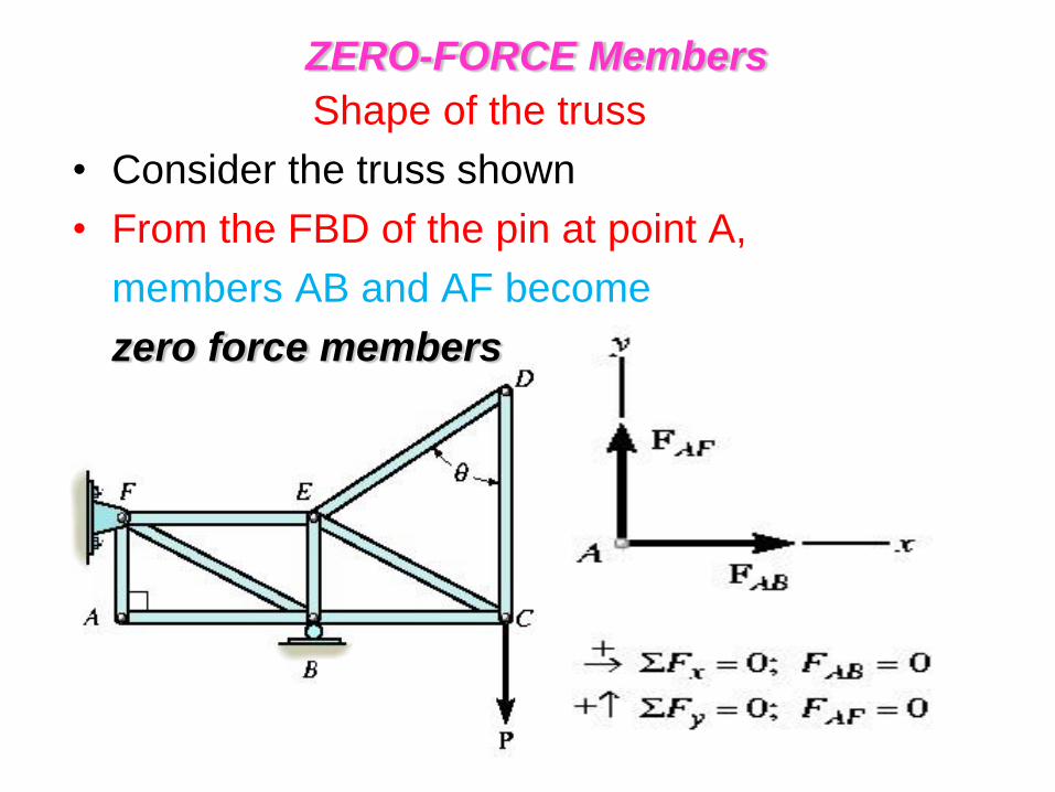
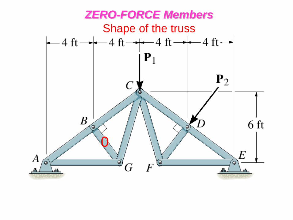
Shape of the truss
• Consider the truss shown
• From the FBD of the pin at point A,
members AB and AF become
zero force members
ZERO-FORCE Members
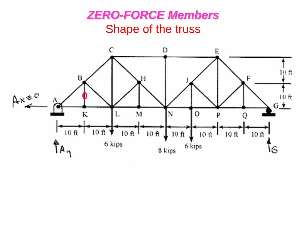
ZERO-FORCE Members
Shape of the truss
• Zero-force members (support no loading )
are used to increase the stability of the
truss during construction and to provide support if the applied loading is changed.
0 0
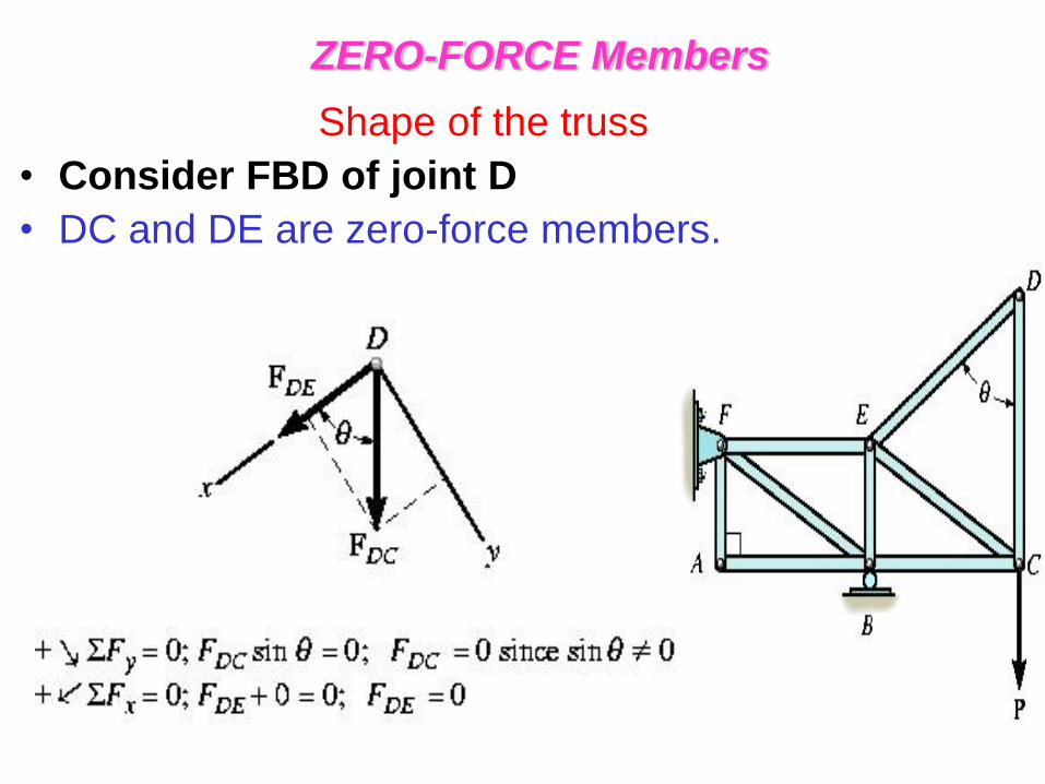
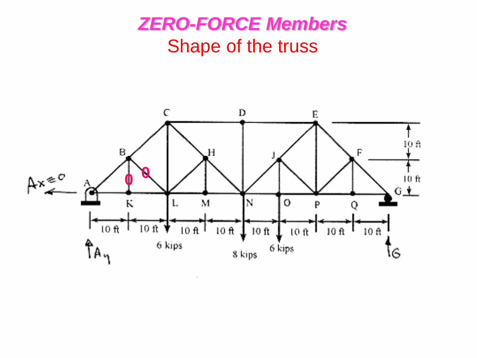
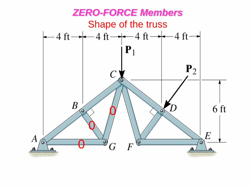
Shape of the truss
• Consider FBD of joint D
• DC and DE are zero-force members.
ZERO-FORCE Members

Shape of the truss
• Consider FBD of joint D
• DC and DE are zero-force members.
ZERO-FORCE Members
0 0
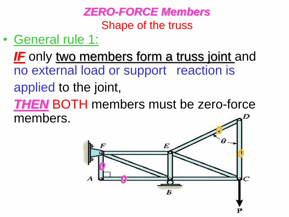
• General rule 1:
IF only two members form a truss joint and no external load or support reaction is
applied to the joint,
THEN BOTH members must be zero-force members.
ZERO-FORCE Members
Shape of the truss
0 0
0
0
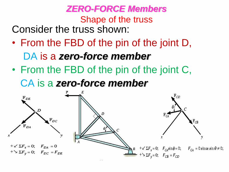
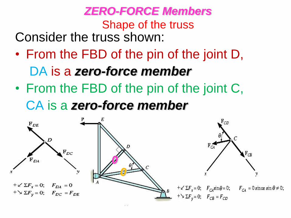
Consider the truss shown:
• From the FBD of the pin of the joint D,
DA is a zero-force member
• From the FBD of the pin of the joint C,
CA is a zero-force member
ZERO-FORCE Members
Shape of the truss
Consider the truss shown:
• From the FBD of the pin of the joint D,
DA is a zero-force member
• From the FBD of the pin of the joint C,
CA is a zero-force member
ZERO-FORCE Members
Shape of the truss
0 0
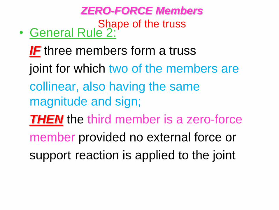
• General Rule 2:
IF three members form a truss
joint for which two of the members are
collinear, also having the same
magnitude and sign;
THEN the third member is a zero-force
member provided no external force or
support reaction is applied to the joint
ZERO-FORCE Members
Shape of the truss
ZERO-FORCE Members
Shape of the truss
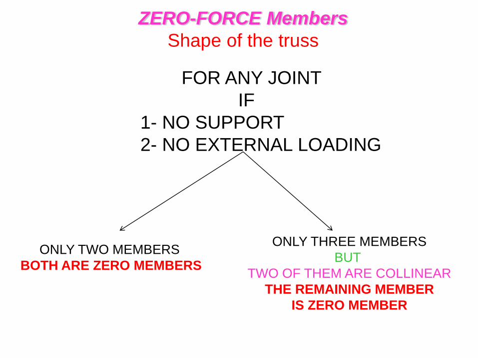
FOR ANY JOINT
IF
1- NO SUPPORT
2- NO EXTERNAL LOADING
ONLY TWO MEMBERS
BOTH ARE ZERO MEMBERS
ONLY THREE MEMBERS
BUT
TWO OF THEM ARE COLLINEAR
THE REMAINING MEMBER
IS ZERO MEMBER
ZERO-FORCE Members
Shape of the truss
0
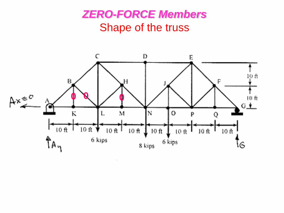
ZERO-FORCE Members
Shape of the truss
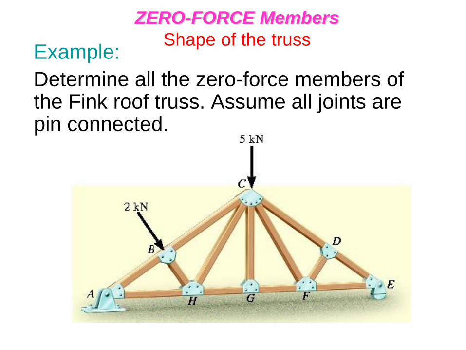
Example:
Determine all the zero-force members of the Fink roof truss. Assume all joints are pin connected.
ZERO-FORCE Members
Shape of the truss
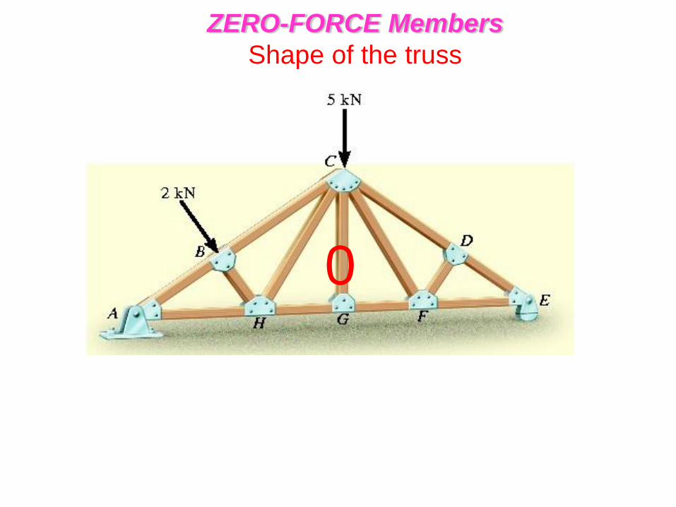
0
ZERO-FORCE Members
Shape of the truss
0 0
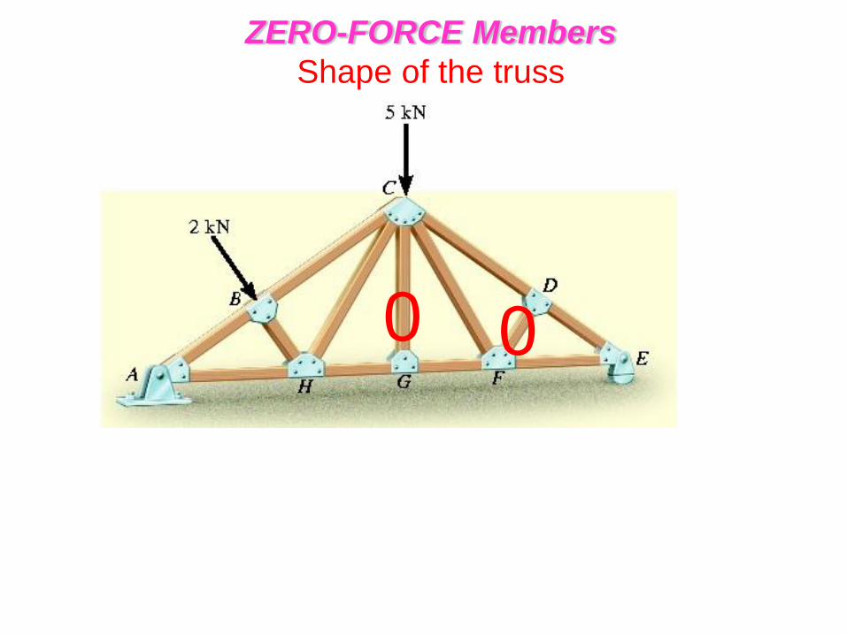
ZERO-FORCE Members
Shape of the truss
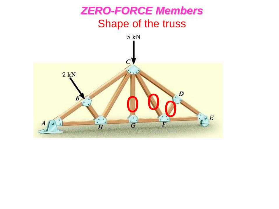
0 0 0
ZERO-FORCE Members
Shape of the truss
ZERO-FORCE Members
Shape of the truss
0
ZERO-FORCE Members
Shape of the truss
0 0
ZERO-FORCE Members
Shape of the truss
0 0 0
ZERO-FORCE Members
Shape of the truss
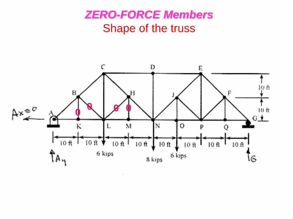
0 0 0 0
ZERO-FORCE Members
Shape of the truss
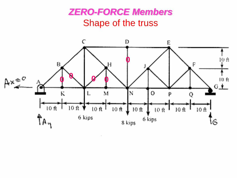
0 0 0 0
0
ZERO-FORCE Members
Shape of the truss
0 0 0 0
0
0
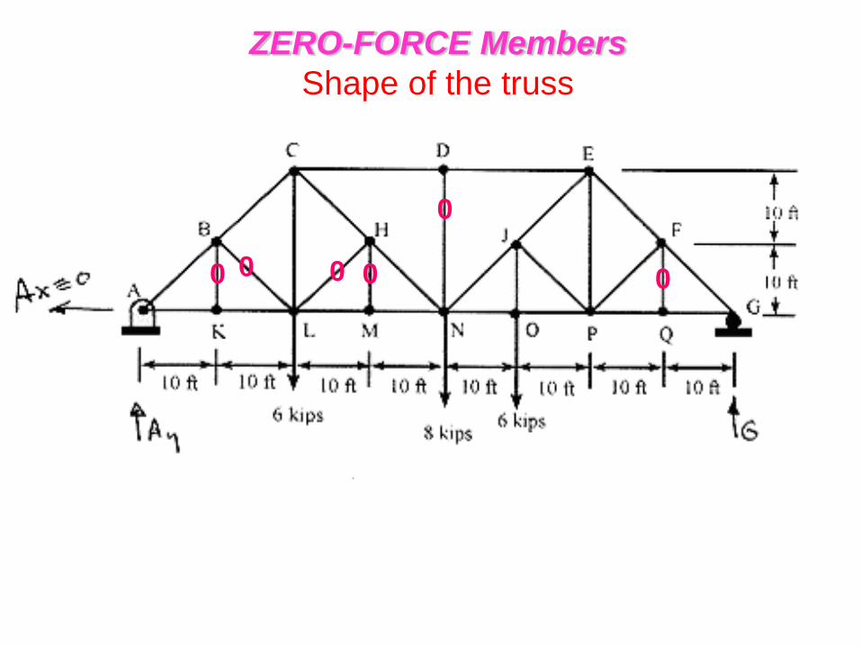
ZERO-FORCE Members
Shape of the truss

0
0 0 0 0 0 0
ZERO-FORCE Members
Shape of the truss
ZERO-FORCE Members
Shape of the truss
0
ZERO-FORCE Members
Shape of the truss
0
0
0
ZERO-FORCE Members
Shape of the truss
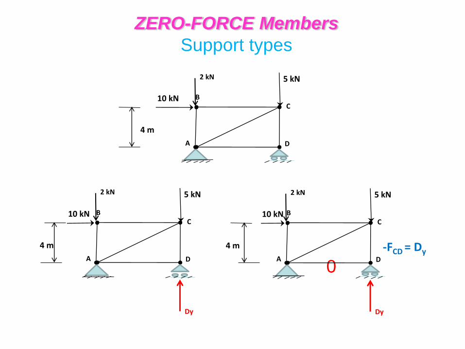
0
-FCD = Dy
ZERO-FORCE Members
Support types
4 m
10 kN B
A
C
D
5 kN 2 kN
4 m
10 kN B
A
C
D
5 kN
Dy
2 kN
4 m
10 kN B
A
C
D
5 kN
Dy
2 kN
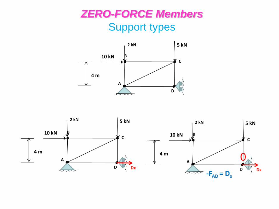
-FAD = Dx
ZERO-FORCE Members
Support types
4 m
10 kN B
A
C
D
5 kN
2 kN
4 m
10 kN B
A
C
D
5 kN
Dx
2 kN
0
4 m
10 kN B
A
C
D
5 kN
Dx
2 kN
No zero member
-FCD = Dy
-FAD = Dx
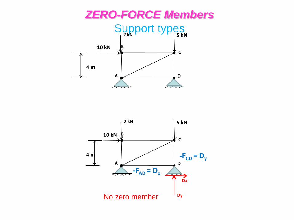
ZERO-FORCE Members
Support types
4 m
10 kN B
A
C
D
5 kN
2 kN
4 m
10 kN B
A
C
D
5 kN
Dy
Dx
2 kN
No zero member
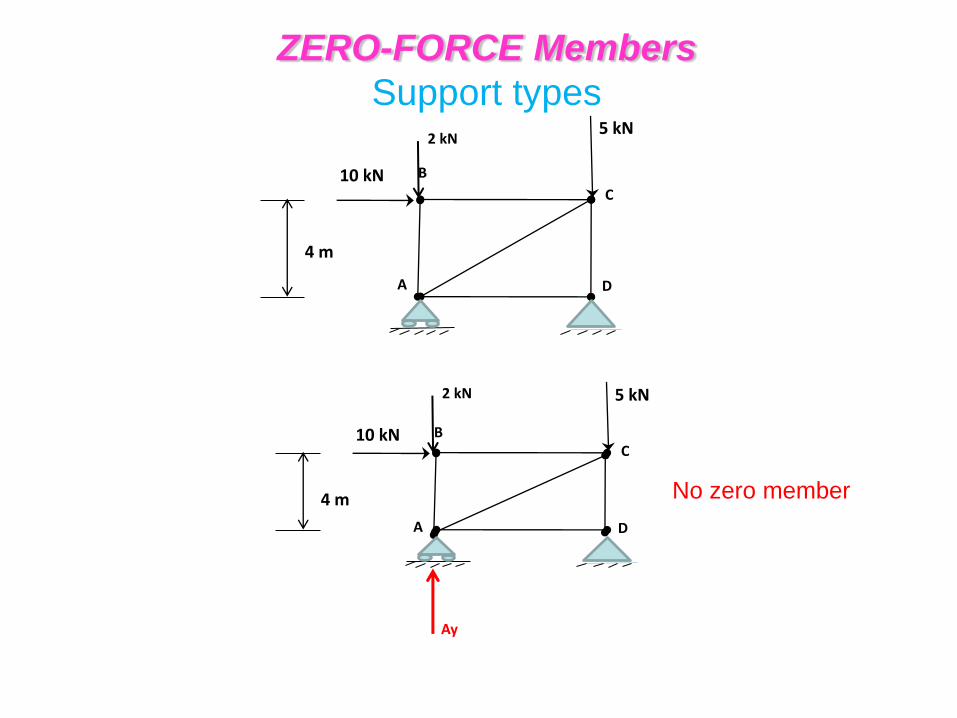
ZERO-FORCE Members
Support types
4 m
10 kN B
A
C
D
5 kN
2 kN
4 m
10 kN B
A
C
D
5 kN
Ay
2 kN
4 m
10 kN B
A
C
D
5 kN
4 m
10 kN
B
A
C
D
5 kN
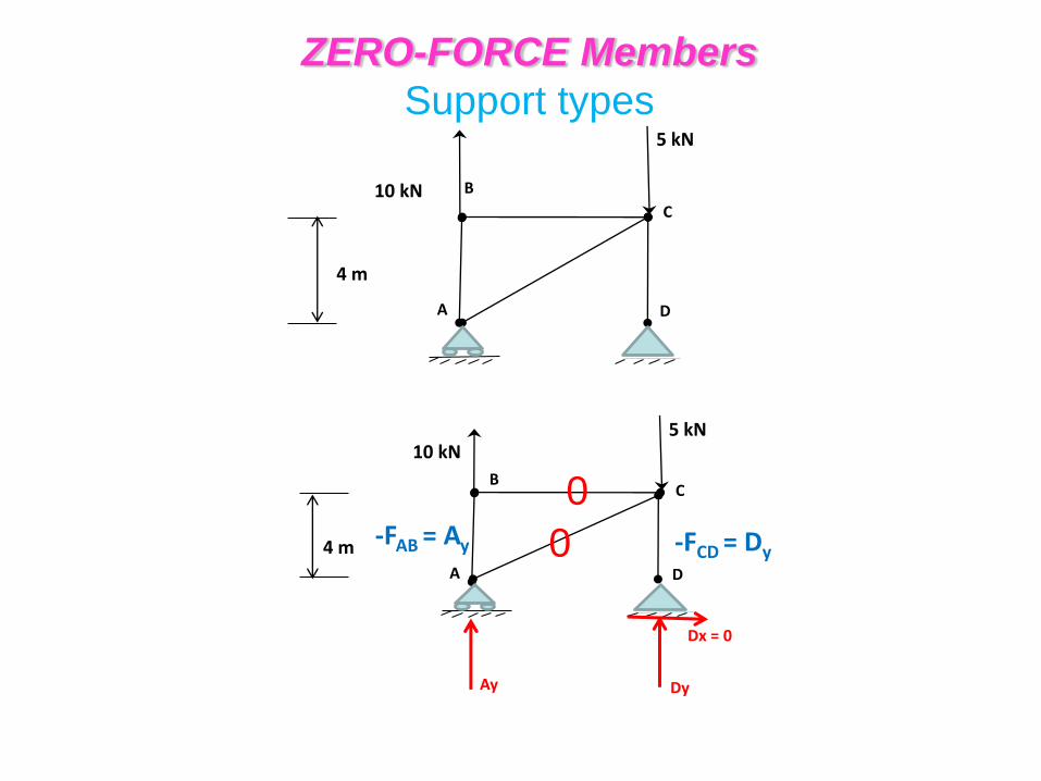
Ay
0 -FAB = Ay
Dy
Dx = 0
-FCD = Dy
ZERO-FORCE Members
Support types
0
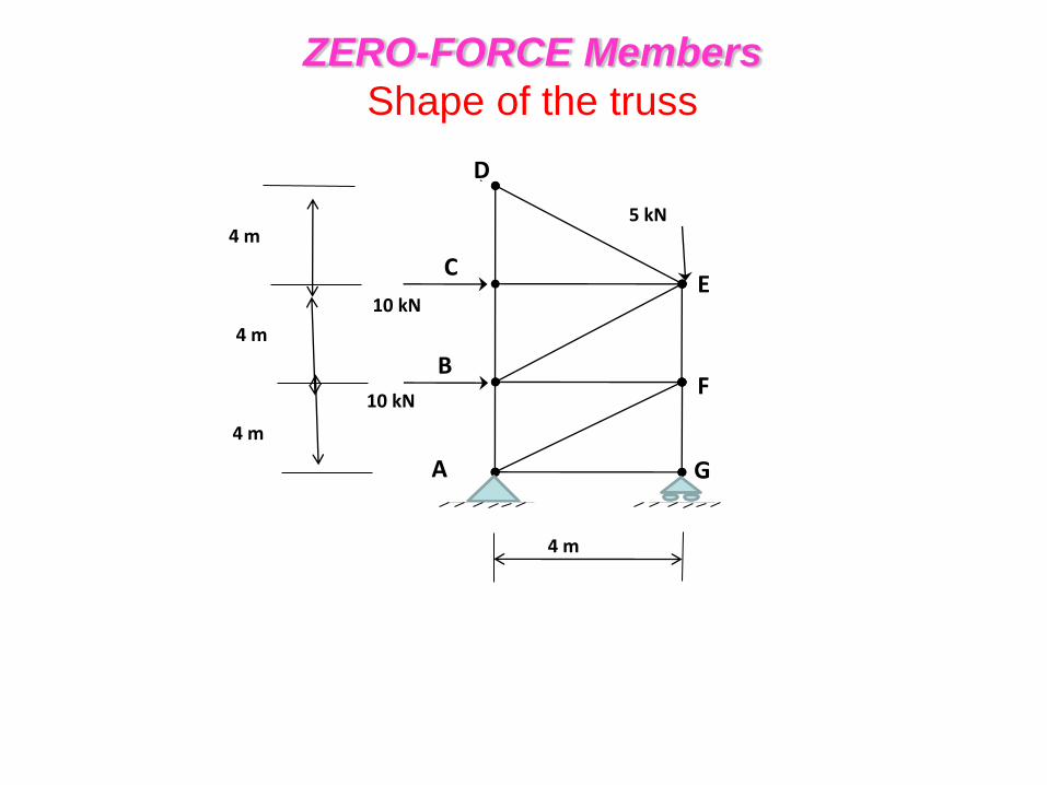
4 m
4 m
4 m
5 kN
10 kN
10 kN
4 m
B
A
C
D
E
F
G
5 kN
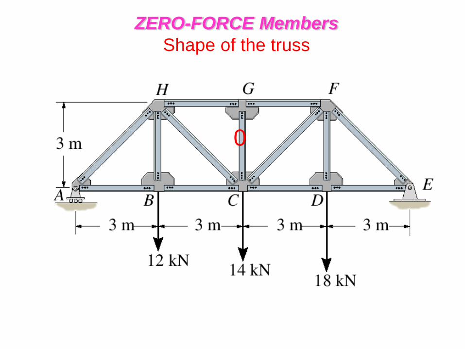
ZERO-FORCE Members
Shape of the truss
4 m
4 m
4 m
5 kN
10 kN
10 kN
4 m
B
A
C
D
E
F
G
5 kN
0 0
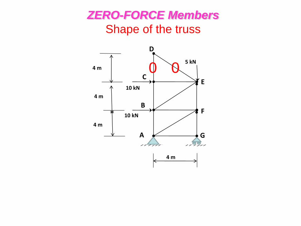
ZERO-FORCE Members
Shape of the truss
4 m
4 m
4 m
5 kN
10 kN
10 kN
4 m
B
A
C
D
E
F
G
5 kN
0 0
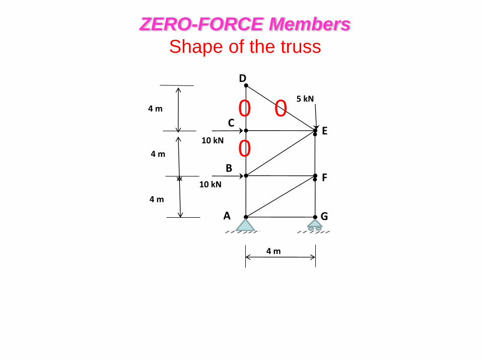
ZERO-FORCE Members
Shape of the truss
0
0 0
0
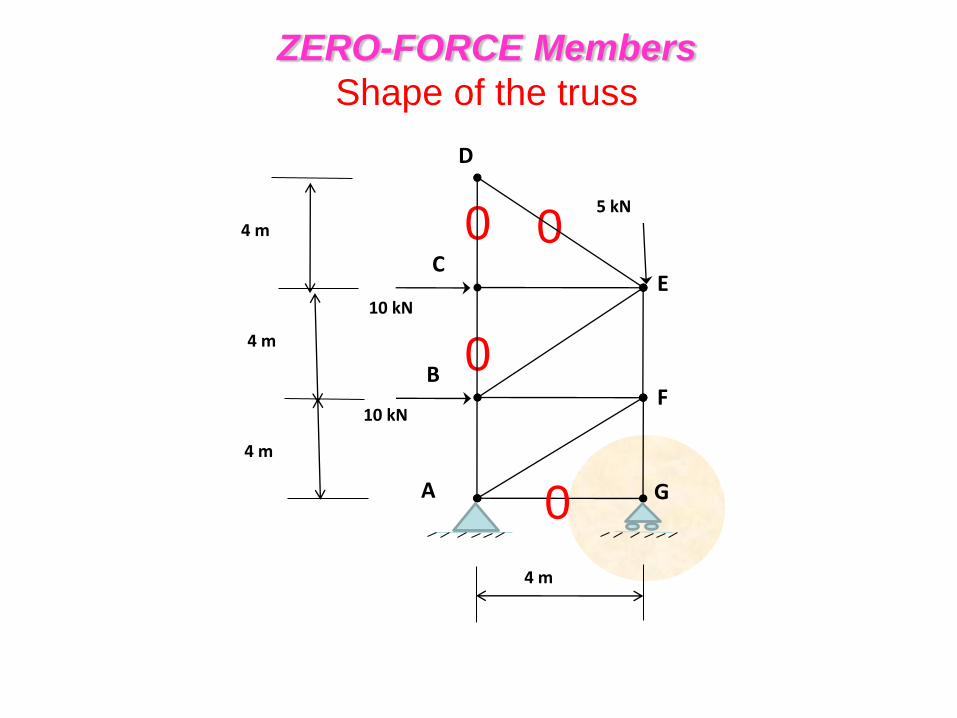
ZERO-FORCE Members
Shape of the truss
4 m
4 m
4 m
5 kN
10 kN
10 kN
4 m
B
A
C
D
E
F
G
5 kN
0
Summary
Truss Analysis
• A simple truss consists of triangular
elements connected by pin joints.
• The force within determined by assuming
all the members to be two force member,
connected concurrently at each joint.
Summary
Method of Joints
• For a coplanar truss, the concurrent force at
each joint must satisfy force equilibrium
• For numerical solution of the forces in the
members, select a joint that has FBD with at
most 2 unknown and 1 known forces
Summary
Method of Joints
• Once a member force is determined, use its
value and apply it to an adjacent joint.
• Forces that PULL the joint are in Tension.
• Forces that PUSH the joint are in Compression.
Summary
Method of Joints
• To avoid simultaneous solution of two
equations, sum the force in a direction that
is perpendicular to one of the unknown.
• To simplify problem-solving, first identify all
the zero-force members.