strike-slip fault-propagation cleavage in carbonate rocks ... · strike-slip fault-propagation...
TRANSCRIPT

Strike-slip fault-propagation cleavage in carbonate rocks: theMattinata Fault Zone, Southern Apennines, Italy
Francesco Salvinia,*, Andrea Billi a, Donald U. Wiseb
aDipartimento di Scienze Geologiche, UniversitaÁ Roma Tre, Largo S. L. Murialdo 1, 00146 Rome, ItalybDepartment of Geosciences, Franklin and Marshall College, P.O. Box 3003, Lancaster, PA 17604-3003, USA
Received 2 July 1998; accepted 8 June 1999
Abstract
Disjunctive, spaced solution cleavage in carbonate rocks is genetically associated with the propagation of the left-lateral,
strike-slip Mattinata Fault in the Gargano Promontory, Italy. Typical cleavage development is restricted within the 200±300-m-wide fault zone, which is bounded by virtually unfractured wall rocks. The cleavage consists of sub-parallel solution surfaces,which are often reactivated as sheared solution planes. Geometrical and kinematic relationships exist between the fault and theassociated cleavage planes, thus: (1) cleavage±fault intersection lines lie parallel to the fault and the sheared cleavage rotational
axes and (2) the cleavage±fault angle is almost constantly equal to 408. A model for the development of the Mattinata Fault isproposed in which the cleavage surfaces are interpreted as fault-propagation deformations. Cleavage nucleates as solution planesat the front of the advancing fault as the result of stress concentration in this region. Two distinct, time-sequential processes are
shown to operate during the fault propagation: (1) typical millimetre- to centimetre-spaced solution surfaces form in the distaltip zone of the advancing fault plane; (2) as the tip advances, the fault plane breaks through the cleavage as minor sheardisplacements reactivate some of these nascent surfaces. These observations may prove useful in understanding mechanisms for
fault-controlled enhanced/reduced permeability and ¯uid pathways. # 1999 Elsevier Science Ltd. All rights reserved.
1. Introduction
The role of pressure solution in cleavage formation
has been widely recognised in di�erent tectonic and
lithological environments in the work of several
authors (Sharpe, 1847; Sorby, 1853, 1856; Nickelsen,
1972; Groshong, 1975; Alvarez et al., 1976; Mitra et
al., 1984; Marshak and Engelder, 1985). Somewhat
uniformly spaced but irregular and locally stylolitic
surfaces with residues of insoluble materials are now
regarded as the hallmarks of the pressure solution cre-
ation process (Stockdale, 1922; Dunnington, 1954;
Park and Schot, 1968; Guzzetta, 1984). The generally
accepted origin is from maximum shortening parallel
to the stylolite teeth (Dieterich, 1969; Carannante and
Guzzetta, 1972; Siddans, 1972) with a time frame slow
enough for operation of the chemical processes of sol-
ution, transport and redeposition (Weyl, 1959; Rutter,
1976, 1983; Groshong, 1988; Andrews and Railsback,
1997). Even though these mechanisms occur in a fault
zone, the chemical time constraint excludes formation
as an instantaneous co-seismic event (Gratier and
Gamond, 1990).
Solution surfaces/cleavages can develop compara-
tively uniformly across signi®cant parts of orogenic
zones (Illies, 1975; Bell, 1978; Illies and Greinier, 1978,
1979; Engelder and Geiser, 1979; Odom et al., 1980;
Mitra et al., 1984; Marshak and Engelder, 1985; Mitra
and Yonkee, 1985; Ohlmacher and Aydin, 1995) or as
planes of localised development in association with
folds (Choukroune, 1969; Alvarez et al., 1976;
Henderson et al., 1986) and/or faults (Arthaud and
Mattauer, 1969; Rispoli, 1981; Gaviglio, 1986;
Nickelsen, 1986; Pollard and Segall, 1987; Aydin,
1988; Hyett, 1990; Ohlmacher and Aydin, 1995, 1997;
Peacock and Sanderson, 1995a, b; Petit and Mattauer,
Journal of Structural Geology 21 (1999) 1731±1749
0191-8141/99/$ - see front matter # 1999 Elsevier Science Ltd. All rights reserved.
PII: S0191-8141(99 )00120 -0
www.elsevier.nl/locate/jstrugeo
* Corresponding author.
E-mail address: [email protected] (F. Salvini)

Fig. 1. Index maps. (a) Geological map of the Mid-Adriatic Region. Square inset shows the geodynamic framework of Southern Italy. (b)
Geological map of the study area.
F. Salvini et al. / Journal of Structural Geology 21 (1999) 1731±17491732

1995; Willemse et al., 1997; Kelly et al., 1998; Peacocket al., 1999). Mechanisms associated with the near-tipstress of advancing faults are increasingly recognisedas signi®cant factors in the development of solutionsurfaces (Gaviglio, 1986; Pollard and Segall, 1987;Aydin, 1988; McGrath and Davison, 1995; Petit andMattauer, 1995; Homberg et al., 1997; Ohlmacher andAydin, 1997). Since the work of Gri�th (1924), it hasbeen shown that sliding on a pre-existing ¯aw leads toa concentration of the stress around the growing ¯aw.The near-tip stress concentration may generate dilationcracks (i.e. wing cracks or tail cracks, sensu Brace etal., 1966 and Cruikshank et al., 1991) which normallyoccur in the tensile quadrants, at a sharp angle fromthe sliding ¯aw (Pollard and Segall, 1987). Wing crackshave been also shown to emanate from one or bothends of the planar ¯aw loaded in shear in brittlehomogeneous isotropic materials during experimentalstudies (Sheldon, 1912; Brace and Bambolakis, 1963;Erdogan and Sih, 1963; Hoek and Beniawski, 1965;Nemat-Nasser and Horii, 1982; Horii and Nemat-Nasser, 1985, 1986; Ashby and Hallam, 1986). In somematerials, such as carbonate rocks, in addition to wingcracks, the near-tip stress concentration may also alter-natively generate solution surfaces which occur on theopposite, contracting quadrants (Arthaud andMattauer, 1969; Rispoli, 1981).
A number of researchers have dealt with the kinkangle of wing cracks and solution surfaces and theirtendency for near-tip nucleation (Irwin, 1957; Ida,1972; Cotterell and Rice, 1980; Pollard and Segall,1987; Cox and Scholz, 1988; Petit and Barquins, 1988;Aydin and Schultz, 1990; Reches and Lockner, 1994;Petit and Mattauer, 1995; Cooke and Pollard, 1996;Cooke, 1997; Martel, 1997; Willemse, 1997; Willemseet al., 1997; Willemse and Pollard, 1998), providingdi�erent solutions according to speci®c boundary con-ditions and to speci®c adopted mechanical theories. Aswell as the opposite tensile/compression stress concen-trations at the fault tip sides, sliding along a pre-exist-ing fault also generates a region of increased stresswhich extends from the fault tip to the region justahead of it (Chinnery, 1963; Pollard and Segall, 1987;King et al., 1994). The stress concentration is respon-sible for the propagation of the fault surface by shear-ing. With progressive increase of the stress, theunfaulted rock in front of the fault plane is elasticallydistorted until the rock strength is overcome and therupture propagates by shear. Experiments have shownthat the size of the region of the increased stress aheadof the tip scales with the fault width (Pollard andSegall, 1987; Lyakhovsky et al., 1997) and linearlywith the fault length (Chernyshev and Deanman, 1991;Scholz et al., 1993; Reches and Lockner, 1994). As aconsequence, deformations deriving from the stressconcentration in the near-tip zone may a�ect a larger
region when associated with the propagation of a re-gional size fault (Reches and Lockner, 1994).
In our paper, we propose that this strain mechanismoperated at the advancing front of the Mattinata Faultin the Gargano Promontory (Fig. 1), Italy, to generatelocalised solution-based fault-propagation cleavage.The genetic process considered here di�ers substan-tially from simple wing cracking mechanisms.
The cleavage analysed in this paper is restricted tothose carbonate rocks of the Gargano Promontorylying within a 200±300-m-wide zone of deformation as-sociated with the regional, left-lateral, strike-slipMattinata Fault (Funiciello et al., 1988) and some ofits adjoining faults (Fig. 1). No cleavages are foundoutside the fault zones. These faults are part of the E±W-trending mid-Adriatic Line de®ned by abruptchanges in morphological, structural and seismic fea-tures within the Adriatic Sea (Favali et al., 1993a, b).The Line represents a roughly E±W kinematic bound-ary across the Adriatic domain, extending from theTremiti Fault and the Tremiti Islands in the north toseveral faults of the Gargano Promontory in the south(Fig. 1).
The well-exposed Mattinata Fault within the Meso-Cenozoic carbonate rocks of the Gargano Promontorywas used to analyse cleavage features and cleavagespatial distribution within a fault zone. Comparisonswere made with the cleavage population sampledalong the adjacent Rignano Fault (Fig. 1).
The aim of this paper is to show that within regionalfault zones in carbonate rocks, cleavage surfaces mayhave a distribution which derives from concentrationof the stress within the virgin rock at the front of thepropagating fault tip. The studied cleavage di�ersfrom the S-planes of Berthe et al. (1979) by thebroader scale at which it forms and by the brittle orsemi-brittle (sensu Davis and Reynolds, 1996) natureof the shear zone to which it is associated.
The model of development of cleavages within theMattinata Fault relies on a ®eld-based fault zonecharacterisation. The Mattinata Fault is exposed for afew tens of kilometres within thick carbonate succes-sions. A series of exposures along the fault providea rather detailed but discontinuous record of thefault zone-related deformations. A speci®c method ofautomated data processing (see Appendix) helpedin solving the problem of spatially analysing datagathered at discrete discontinuous sites along aregional fault.
We analyse the cleavage sets of the Mattinata Faultand establish a number of geometrical and kinematicrelationships between the fault and the associated clea-vage system. The results are compared with those fromthe adjacent Rignano Fault. Based on these obser-vations, we propose a model for the development ofthis cleavage as a fault-propagation structure. In ad-
F. Salvini et al. / Journal of Structural Geology 21 (1999) 1731±1749 1733

Fig. 2. (a) Photograph of an active quarry wall illustrating a section across the Mattinata Fault Zone (Valle Carbonara). In the photograph, the
fault core, characterised by master slip planes encompassed by cataclasites and gouges, can be observed. Within the core, relics of the bedding
surfaces are still preserved. (b) Photograph of an abandoned quarry (south of S. Marco in Lamis) illustrating almost unfractured limestone beds
belonging to the Mattinata Fault wall rocks. In the quarry, large blocks of undeformed limestone were once obtained. The only obvious struc-
tures at this scale are large asystematic joints. (c) Photograph illustrating details of a limestone bed from (b). Stylolitic surfaces parallel to bed-
ding are observable at this scale.
F. Salvini et al. / Journal of Structural Geology 21 (1999) 1731±17491734

Fig. 3. Photographs and block diagrams showing cleavages in carbonate rocks. (a) Photograph mostly illustrating interbed cleavage planes cut-
ting across the bedding surface. (b) Photograph mostly illustrating intrabed cleavage planes abutted by bedding surfaces. (c) Photograph illustrat-
ing a bedding surface with a NW±SE sutured intersection lineation of a cleavage plane. Note the millimetre right-lateral o�set of the teeth and
the consistent opening of the NE±SW dilation fractures at the two extensional quadrants of the cleavage tips. Arrows indicate the sense of displa-
cement by pressure solution and shear. (d) Photograph illustrating a bedding surface with a N±S set of e chelon cleavage smooth intersection
lineations. Note the dilation fractures opening at the cleavage tips, which show a left lateral o�set. Arrows indicate the sense of displacement by
shear. (e) Block diagrams illustrating the typical pattern of cleavage surfaces a�ecting carbonate beds. Millimetre- to centimetre-spaced solution
surfaces (thinner lines) are contained within lithons bounded by decimetre-spaced sheared solution surfaces (thicker lines). Solution surfaces
develop within carbonate layers mostly as intrabed planes, whereas the sheared solution surfaces may propagate across the bedding planes as
interbed planes.
dition to throwing some light on fault tip processes,these observations may prove useful in understandingpermeability and ¯uid paths associated with some faultzones in carbonate rocks. The methodology weadopted to quantitatively assess the changing azimuthsof the cleavage pattern along strike is dealt with in theAppendix at the end of the paper.
2. The Gargano Promontory
The Gargano Promontory is easily identi®ed as anENE-elongated prominence along the Italian Adriaticcoast (Fig. 1). The promontory is part of the ApulianPlatform, the foreland for both the Apennine(Miocene±Pleistocene) and the Dinaride (Eocene±Miocene) thrust and fold belts (Fig. 1a). Its lithologydeveloped in the Adriatic microplate (Biju-Duval etal., 1977; Vandenberg, 1979; HsuÈ , 1982; Manzoni andVandenberg, 1982; Funiciello et al., 1991; Favali et al.,1993a, b) as part of the Apulian Mesozoic carbonateshelf along a passive margin of the Tethys Ocean.
The Gargano area is underlain by more than 4000 mof a discontinuous marine carbonate sequence rangingin age from Triassic to Middle Miocene. Prevailingshallow water carbonates crop out in the central andwestern sectors of Gargano, whereas to the east andnortheast such sequences are progressively bounded byMesozoic carbonate slope and basin deposits (Boselliniet al., 1993 and references therein).
The promontory is a left-lateral, transpression-re-lated, asymmetric, anticlinal high with the axis trend-ing WNW±ESE (Fig. 1a). Mesozoic carbonateformations rise to over 1000 m above sea level in thepromontory whereas the same formations reach only500±600 m in most of the adjacent plains. Dissectingthe promontory along its approximate anticlinal hingeis the Gargano Shear Zone, an E±W trending regionof left-lateral o�set (Fig. 1a) characterised by a patternof well de®ned, E±W and NW±SE-trending faults.Minor, local, NW±SE strike-slip related folds are con-sistent with the left-lateral tectonics. The southern sec-tor of the Gargano Shear Zone is characterised by thepresence of three major faults, the E±W Mattinata andRignano faults, and the WNW±ESE Candelaro Fault,a feature which bounds the SW corner of the uplift(Fig. 1b). This study focuses on the Mattinata Faultlocated in the south ¯ank of the promontory (Fig. 1b),characterised by carbonate rocks with typical southdips of 20±308.
The Mattinata Fault is the most prominent memberof the Gargano Shear Zone. The fault has an irregulartrace characterised by a number of signi®cant morpho-logical features compatible with left-lateral strike-sliptectonics. Proceeding westward from the coastline,these features include the Mattinata plain (Fig. 1b) as
a narrow triangular depression formed at a counter-clockwise releasing bend of the main fault. Next, theValle Carbonara is a gully located at a 208 clockwisebend of the main fault. Westward, the Pantano S.Egidio pull-apart basin (Guerricchio, 1986; Funicielloet al., 1988) forms a shallow rhomb-shaped depressionat a left-step of the main fault. Toward the westernend, just northwest of the S. Marco in Lamis village(Fig. 1b), a WNW-striking fault branches out from arestraining bend of the main E±W Mattinata Fault toproduce a number of outcrop-scale transpressional fea-tures.
3. The Mattinata fault-related cleavage
The cleavage associated with the Mattinata FaultZone consists of an array of disjunctive, spaced, sol-ution surfaces a�ecting the carbonate rocks within itsentire, exposed fault zone. The Mattinata Fault Zoneranges in width from a few tens of metres to about300 m and is typically about 200 m wide. Its exposedon-shore length of more than 40 km (Fig. 1) is com-posed of two contrasting structural fabrics (Fig. 2a):(1) the fault core and (2) the fault damage zone (Caineet al., 1996). The central core occupies 10±20% of itstotal width. The core includes the master slip surfaceand associated bands of cataclastic breccias andgouges. Because of cataclasis and extensive rock crush-ing, cleavage surfaces are rarely detectable in the corezone. Beyond the core, the broader damage zone con-sists of a network of both sub-parallel and cross-cut-ting subsidiary slip surfaces breaking through massesof intensely cleaved carbonate rocks. The poorlyexposed outer boundaries of the damage zone appearto give out in a few metres to almost undeformed wallrocks (Fig. 2b and c). No cleavages have been foundbeyond this rather abrupt boundary. Within anotherfew 10s to 100 m from the boundary zone, carbonaterocks are nearly undeformed except for poorly devel-
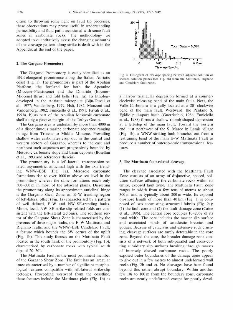
Fig. 4. Histogram of cleavage spacing between adjacent solution or
sheared solution planes (see Fig. 5b) from the Mattinata, Rignano
and Candelaro fault zones.
F. Salvini et al. / Journal of Structural Geology 21 (1999) 1731±17491736

oped systematic intrabed joints. This spatial contrast is
best observed at several quarries located between the
Mattinata and Rignano faults south of S. Marco in
Lamis and S. Giovanni Rotondo (Fig. 2).
The cleavage surfaces investigated within the
Mattinata Fault Zone have nearly vertical dips and a
general NW±SE strike (Fig. 3). Their spacing ranges
from 0.001 to 0.3 m and from 0.01 to 0.03 m on aver-
age (Fig. 4). The spacing of the cleavage surfaces
within the carbonate rocks is found to decrease slightly
in approaching the fault planes. Stylolites (Fig. 3c) as
well as slight truncation of fossils along the cleavage
surfaces reveal their dissolution nature. Strike-slip
slickolites and/or slickensides along some of the clea-
vage planes testify to shear displacement along them.
Locally on bedding surface exposures, dilation frac-
tures with 0.001±0.03 m opening, emanate from and
connect with the tips of closely spaced sheared clea-
vage planes (Fig. 3c). Some lateral o�set of the styloli-
tic teeth or of serrate pro®les observed on bedding
surfaces (Fig. 3c) from cleavage intersections suggests
that shear processes along the cleavage planes post-
date the dissolution. The magnitude of these shear dis-
placements, estimated through the lateral o�set of
markers or through the aperture of the dilation frac-
tures opening at the cleavage termination, is in the
order of 0.001±0.03 m. Adjacent, parallel surfaces can
show di�ering evolutionary development: formation of
the plane by simple solution with some planes showing
later shearing along the solution surfaces (Fig. 3).
Solution surfaces are typically intrabed structures
whose development halts top and bottom at bedding
planes (Fig. 3b). On the other hand, sheared solution
surfaces commonly cut across bedding planes (interbed
surfaces in Fig. 3a). Evidence of younger shear displa-
cement is found along a more limited number of the
cleavage surfaces with typical spacing of 0.1±1 m. The
typical pattern is of 0.001±0.1-m-spaced solution sur-
faces lying within 0.1±1-m-wide lithons which are
Fig. 5. (a) Three-dimensional sketch illustrating geometrical and kin-
ematic relationships between fault and cleavage planes. The intersec-
tion line between the cleavage and the fault planes lies parallel to the
fault rotational axis. (b) Map view of (a). Cleavage planes form an
acute angle with the fault plane (cleavage±fault, CF angle). In
approaching the fault plane this angle decreases with progressive
bending of the cleavage planes into closer parallelism with the fault
surface. Development of fault breccia along the fault plane generates
free boundaries between the fault and the cleavage surfaces.
Fig. 6. Contoured stereograms (Schmidt projections, lower hemisphere) of the structural data sampled within the Mattinata Fault Zone.
F. Salvini et al. / Journal of Structural Geology 21 (1999) 1731±1749 1737

Fig. 7. (a) Rose diagrams showing cleavage azimuths from speci®c segments of the Mattinata Fault. Arrows indicate areas (shaded in b) of data
sampling. (b) Trace of the Mattinata Fault and area (A±A ') along the structural transect swath. (c) Structural transect diagrams representing
cleavage azimuth frequency versus distance along the transect swath (A±A '). The top diagram represents the raw data, the middle diagram is a
bimodal Gaussian ®t, and the bottom one is a unimodal Gaussian ®t.
F. Salvini et al. / Journal of Structural Geology 21 (1999) 1731±17491738

Fig. 8. Cleavage azimuths rotated to conform to an idealised Mattinata Fault having perfect E±W strike. (a) Trace of the Mattinata Fault and
location (A±A ') of the structural transect swath. (b) Frequency of rotated cleavage azimuths with distance along the transect swath (A±A '). Thelocal fault azimuth was determined for each sample location and the data azimuths were then rotated to conform to a ®ctitious E±W striking
fault. (c) Lines representing the highest gaussian peaks from (b) showing the nearly constant mean trend of the rotated cleavage azimuths along
the transect. (d) Original unrotated data repeating diagram from the bottom of Fig. 7(c). Note the decrease in scatter of (b) and (c) with respect
to (d). (e) Rose diagram for the unrotated azimuthal cleavage data represented in (d). In grey is the histogram, in black is the curve resulting
from the unimodal Gaussian ®t. (f) Rose diagram for the rotated azimuthal data represented in (b). Histogram in grey, the curve resulting from
the unimodal Gaussian ®t is shown in black.

bounded by an interconnecting network of sheared sol-ution surfaces and associated tip structures (Fig. 3e).
The sense of the shear displacement on the faultsand on the associated sheared cleavage planes is syn-thetic. As a rule, the fault±cleavage intersection linesare normal to the strike-slip slickenlines (sensu Davisand Reynolds, 1996) on the fault surfaces as well asnormal to the slickenside and/or slickolite lineationsdeveloped on the sheared solution cleavages, i.e. ro-tational axes (Wise and Vincent, 1965; Salvini andVittori, 1982) of faults and of sheared solution surfacesare nearly parallel (Figs. 5 and 6).
Despite the observed shear displacement, the clea-vage planes are never found to cross-cut or displacethe related fault plane. The fault±cleavage intersectionzone is normally a site of cataclastic, silt-sized carbon-ate grains forming a free boundary for fault slippage(Fig. 5b). Here, cleaved rocks show progressive com-minutation into fault breccia or microbreccia. Inapproaching such a free boundary, the cleavage planesmay be slightly convex in the direction of the relativefault slip (Fig. 5b).
4. Analysis of structural data
The total dataset from 42 sample sites within theMattinata Fault Zone includes geometric and kin-ematic observations on a total of 2230 cleavage sur-faces and 195 fault surfaces (Fig. 6).
Meso-scale faults within the Mattinata Fault Zoneare strike-slip sub-vertical planes, which may begrouped into four main populations (Fig. 6): (1) E±Wleft lateral; (2) N558W left-lateral; (3) N708E left-lat-eral; and (4) N208E right-lateral. Cleavages in theMattinata Fault Zone are sub-vertical planes rangingin strike from nearly E±W to N108W. A small clusteron the ®gure indicates a few cleavages striking N508Wwith south dips.
Plotting cleavage data as separate rose diagrams(Fig. 7a) from the various segments of the MattinataFault (Fig. 7b) illustrates the heterogeneous patternalong strike of the fault. A more continuous spatialoverview of details of changing cleavage azimuthsalong strike appears in the structural transect plots(Fig. 7c) in which cleavage azimuths are plotted by fre-quency versus the along-transect distance (seeAppendix). Data plotted in these diagrams are clea-vage azimuths from stations along the A±A ' transectswath of Fig. 7(b). The histogram diagram (above Fig.7c) displays the frequency of the raw dataset, whereasin the bi- and unimodal Gaussian ®t diagrams (lowerin Fig. 7b) the dataset is ®ltered by bi- and unimodalGaussian distributions, respectively, to show the maintrends (see Appendix). In these diagrams, it is observedthat the azimuths of the sampled cleavages tend to
rotate clockwise or counter-clockwise from the overallN508W trend (Fig. 6), respectively, in concert with theclockwise or counter-clockwise deviations of the faulttrace from its average E±W orientation. The cleavagetrend becomes nearly E±W along the N508E fault seg-ments in the two pull-apart basins and N208W alongthe N608W fault segments northwest of S. Marco inLamis and west of Monte S. Angelo (Fig. 7a and c).On the other hand, where the fault trace is E±Woriented, cleavages tend to cluster along the N508Wdirection. The comparison between the bi- and theunimodal Gaussian ®ts (Fig. 7c) shows that the twoGaussian curves identi®ed in the bimodal distributionare close enough to ®t into a unimodal Gaussian dis-tribution.
5. The cleavage±fault angle
The cleavage±fault (CF) angle is here de®ned as thedihedral angle between the cleavage and the faultplane (Fig. 5). As seen in the previous section, thevariations in azimuth of the Mattinata Fault seem tocorrespond to equivalent variations in strike of the as-sociated cleavage surfaces. Therefore, a rather constantCF angle can be seen to occur along the entire lengthof the fault. As a test of this hypothesis, variations inthe CF angle were statistically assessed along a speci®cstructural transect. In that both the Mattinata Faultand its associated cleavages are sub-vertical, the clea-vage±fault angle can be designated as their di�erencein azimuth. To plot local measurements of the CFangle, the local strike of the fault at each station wasdetermined from our ®eld data and/or from maps afterprevious papers (Funiciello et al., 1988 and referencestherein). The cleavage azimuthal data for each localstation were then rotated to correspond to a theoreti-cal E±W fault strike. In this way, the relative con-stancy of the CF angle can be seen as straight lines inFig. 8(b) and (c).
The modi®ed cleavage azimuth dataset was georefer-enced like the original one and then plotted using thesame A±A ' transect swath of Fig. 7(b). From the com-parison between the original cleavage azimuth domain(Fig. 8d and e) and the modi®ed one (Fig. 8b and f),the dependence of the cleavage pattern upon the faultorientation can be inferred. The scattering of the azi-muth population in terms of standard deviation isreduced by 108, from 228 to 128, around a mean azi-muth of about N508W (Fig. 8e and f). The nearly con-stant line of Gaussian peaks at about N508W (Fig. 8c)re¯ects the constancy of the CF angle through thechanges in azimuth of the Mattinata Fault (Fig. 8a).The CF angle slightly increases in the two pull-aparts,whereas the minimum value is reached in the trans-pressional fault segment near Monte S. Angelo.
F. Salvini et al. / Journal of Structural Geology 21 (1999) 1731±17491740

The rose-diagram of Fig. 8(f) represents the cumu-lative histogram and unimodal Gaussian ®t of themodi®ed cleavage population. The mean CF angle ofabout 408, with a standard deviation of 128, can beread as the distance from the mean azimuth value ofthe Gaussian curve (i.e. N508W) to the E±W direction.The mean 408 CF angle value accounts for the normalscattering of the CF angle (i.e. related to fault anasto-mosing, fault branching, and local rheological vari-ations) as well as the opposite variations of the CFangle in the transtensional and the transpressionalfault segments.
6. Comparison with the Rignano Fault
The E±W Rignano Fault is located in the same car-bonate formations about 4 km south of the MattinataFault (Fig. 9a) with an on-shore length of about40 km. The most obvious deformation features along itare sub-vertical minor strike-slip faults and cleavagesurfaces analogous to those along the Mattinata Fault.
Within the Rignano Fault Zone, horizontal slickenlinesalong the fault surfaces and NW±SE solution clea-vages indicate its left-lateral strike-slip kinematics.However, about 400 m of vertical topographic o�setalong this fault as well as vertical slickenlines over-printing horizontal ones suggest a younger verticallymoving reactivation. Exposures along the fault show amean azimuth of cleavage at about N468W with astandard deviation of about 128 (Fig. 9b). Assumingan overall E±W trend of the fault, the resulting aver-age CF angle is equal to 448 (Fig. 9b). Assessments ofthe CF angle in three major exposures along the faultyield values of 468, 398 and 468 (plots of Fig. 9c, d ande) based on the di�erence between the local fault azi-muth and the best Gaussian ®t of cleavage azimuths ateach station (Fig. 9a).
The polar diagram of Fig. 9(f) shows the contoursof the fault rotational axes together with the projectionof the overall E±W vertical fault plane and the averageplane of cleavage (i.e. N468W-striking, 858NE-dip-ping). Plotted fault rotational axes are only those as-sociated with the strike-slip indicators. The plot
Fig. 9. (a) Geological map of the area surrounding the Rignano Fault. For the Legend see Fig. 1. (b) Cumulative rose diagrams for the entire set
of cleavage azimuths sampled along the fault. (c), (d) and (e) Rose diagrams showing cleavage azimuths from speci®c segments of the Rignano
Fault indicated by the connecting lines. In grey is the histogram, in black is the curve resulting from the unimodal Gaussian ®t. Each diagram
also shows the local azimuth of the Rignano Fault as a dashed line to illustrate the relative constancy of the cleavage±fault angle at each site. (f)
Contoured stereogram (Schmidt projections, lower hemisphere) with a single maximum showing the overall parallelism among fault rotational
axes (data no.=45) and the fault±cleavage intersection line.
F. Salvini et al. / Journal of Structural Geology 21 (1999) 1731±1749 1741

Fig. 10. Model for the cleavage nucleation and growth. (a) Stress trajectories for a mode II crack loaded by pure remote shear (modi®ed after
Pollard and Segall, 1987). Longer tics are parallel to the maximum compression stress and shorter tics are parallel to the maximum tensile stress.
Lengths of tics do not indicate stress magnitude. Stresses are normal or parallel to the crack walls that are shear strength free. Shading at the
crack tips schematically indicates the regions of stress concentration in the prolongations of the fault (after Chinnery, 1961, 1963 and Pollard
and Segall, 1987). The scale is not indicated because the model is scale-invariant. In this case, the mode II crack of the ®gure represents an ana-
logue of the Mattinata Fault whose associated zone of deformation is approximately 200 m wide. (b) With fault propagation, the enhanced stress
at the fault tip nucleates solution cleavages in the distal part of the region of stress concentration. As the fault advances some of the nascent clea-
vage planes are reactivated in a dominantly shear mode that includes some slickolite redeposition. Finally, the master fault cuts through all the
tip zone structures producing gouge, breccia and local minor drag of the truncated cleavages.
F. Salvini et al. / Journal of Structural Geology 21 (1999) 1731±17491742

demonstrates the overall parallelism among the sub-vertical lines of fault-cleavage intersection, fault ro-tational axes and rotation axes from the sheared sol-ution surfaces.
7. Model for development of the fault-related cleavage
Key geometric and kinematic features of theMattinata Fault Zone are: (a) a set of parallel, adjoin-ing surfaces form two types of fault-related cleavage,simple solution surfaces and shear reactivated surfaces;(b) the cleavage is restricted to 200±300-m-wide faultzones; (c) the intersection lines between the fault andassociated cleavage surfaces are parallel to the rotationaxes derived from motion indicators on both the faultand the sheared solution surfaces; (d) sense of motionindicators are synthetic for both faults and sheared sol-ution surfaces; and (e) even though the fault azimuthmay change locally, the cleavage±fault angle remainsrelatively constant at about 408.
These features can be synthesised into the followingmodel for the cleavage development (Fig. 10).Cleavage surfaces form during the fault propagationby pressure solution within carbonate rocks strainedby the stress concentration in the region ahead of theadvancing fault tip. Rock strength and relative motionof fault blocks produce a local stress regime (i.e. kin-ematic stress) within this region (Fig. 10b). For relativemovements parallel to the fault plane, maximum andminimum stress axes lie at 458 from the fault plane(e.g. Sanderson and Marchini, 1984). With these con-ditions, the pressure solution planes would develop atan angle of 458 to the fault plane. The average 408cleavage±fault angle found along the Mattinata Faultsuggests a slight rotation of the maximum axis of thelocal stress away from the fault plane. McKinnon andGarrido de la Barra (1998), in numerical experimentsreproducing simple shear-related fracturing and stress®elds, achieved analogous results in which a progress-ive rotation away from the applied shear of the majorprincipal stress arose before fracturing took place.
This model, together with the observations on thespatial distribution of cleavage and its displacementscan be integrated into a fault propagation cleavagemodel for temporal evolution of the Mattinata Fault(Fig. 10). Fault propagation started with the formationof an array of solution surfaces oriented at 408 fromthe fault plane in front of its tip region, where stressconcentration occurs (Chinnery, 1963). The shear dis-placements, synthetic with the fault motion (i.e. leftlateral), of the re-activated cleavage planes suggest thatthe rotation of the stress away from the fault involvedonly the cleavage development regime in the near-tipregion. As the fault zone propagated, the former tipregion was integrated into the fault zone and the sol-
ution cleavages were cut and o�set by the advancingarray of slip planes. With continued slip in the faultzone, where the kinematic stress recovers to its theor-etical orientation (i.e. with the maximum axis at 458from the fault plane), part of the cleavage surfaces wasreactivated according to synthetic strike-slip motions.Once formed, the solution cleavages became signi®cantplanes of anisotropy ready to be reactivated duringsubsequent fault growth. Commonly, dilation wingfractures emanated from the tips of the sheared clea-vage planes to interconnect into a fracture network.For the most part, the shear deformation along thecleavage planes was slow enough to allow some calcitesolution and redeposition as slickolite ®bres.Eventually, with continued slip, the fault core pro-duced gouge and cataclasite as overprints on theslightly older, cleaved damage zone. Minor, local faultdrag of the cleavage planes just beside the slip surfaceoccurred in this phase, resulting in a slight decrease inthe cleavage±fault (CF) angle near the fault plane.This model is analogous to that of Petit and Barquins(1988) in which, properly oriented, e chelon, mode Ifractures rather than solution cleavages, are the pre-cursory structures propagating ahead of the fault tip.
In the absence of appropriate key outcrops, directobservation of tip structures was not possible.Nevertheless, three principal features justify the in-terpretation of the Mattinata Fault cleavage as fault-propagation structures: (1) rock faulting is always an-ticipated by some degree of stress/strain concentrationin front of the growing fault (Chinnery, 1961, 1963;Pollard and Segall, 1987); (2) fault strength weakening(Mandl, 1988) is likely to prevent the development ofnew cleavage surfaces in the fault damage zone oncethe fault core has developed; (3) no cleavages werefound to be associated with the dip-slip reactivation ofthe Rignano Fault.
Several authors (Willemse and Pollard, 1998 andreferences therein) have discussed wing fractures andsolution seams emanating from the termination ofsmall shear fractures (e.g. deformations associatedwith the small faults exposed in carbonates from theLanguedoc region, France; Rispoli, 1981). Theyobserved that veins and pressure solution surfacesemanate from near the ends of small, left lateral faultsand hypothesised that the tensile/compressive stressconcentrations at the fault tip sides, resulting from slipon the faults, caused the veins and solution surfaces toform and propagate away from these structures.Pollard and Segall (1987) numerically demonstratedthat these features have a theoretical kink angle (sensuWillemse and Pollard, 1998) of 70.58 from the faultplane. Willemse and Pollard (1998) presented analyti-cal solutions for the case of a zone of high strength orfriction at a shear crack termination (Ida, 1972;Palmer and Rice, 1973; Cowie and Scholz, 1992). They
F. Salvini et al. / Journal of Structural Geology 21 (1999) 1731±1749 1743

Fig. 11. Structural transect methodology applied to (®ctitious) cleavage azimuth data along the Mattinata Fault. (a) Example of a transect swath
including the Mattinata Fault zone in the Gargano area. The white rectangular box is the area of the A±A ' transect swath. The white-®lled dots
represent (®ctitious) sample stations in the Gargano area. Two boxes within the transect swath are examples of sequential analysis boxes. Data
contained in each of these boxes are those extracted to form the raw dataset of each single histogram in (b). The analysis box is advanced by the
analyis step. The analytical process is then repeated at each step to complete the A±A ' transect swath. Some overlap of the extraction boxes is
used to smooth the data along the structural transect plots. (b) Construction of the structural transects by adding in sequence, along the length
of the transect, the single histograms (or Gaussian ®ts/peaks). Each histogram refers to a single extraction box and occupies along the transect
plot, a width equal to the analysis step along the transect swath. (c) Stages in azimuth±frequency Gaussian ®tting analysis. From left to right:
raw data histogram; raw data histogram (grey) and smoothed histogram (black); raw data histogram (grey) and unimodal Gaussian ®t curve
(black); raw data histogram (grey) and bimodal Gaussian ®t curves (black); raw data histogram (grey) and polymodal Gaussian ®t curves
(black).

showed that instead of emanating from the tip sides,the tip structures can develop straight through thecrack plane slightly ahead of the tips, with drastic re-duction in the theoretical kink angle. In addition tothe size of the structures, at least two important issuesdistinguish the solution cleavage within the MattinataFault Zone from that of fault-related wing surfaces.(1) Solution (wing) seams associated with small faultsare spatially distributed as isolated or discrete smallarrays of surfaces along the fault plane, typically atthe fault tips. Cleavage within the Mattinata FaultZone is made of closely spaced planes continuousthroughout the entire fault length. (2) Solution seamsassociated with small faults are restricted to the twonear-tip contractional quadrants and are hypothesisedto develop mostly by the local increase in the meannormal component of the stress ®eld (Pollard andSegall, 1987). Cleavage within the Mattinata Faultdevelops by the stress concentration in the pro-longation of the advancing fault.
8. Conclusions
1. Solution cleavages that characterise the MattinataFault Zone developed in carbonate rocks of theGargano Promontory. The cleavage is con®nedwithin the about 200-m-wide fault zone.
2. Within the framework of the Mattinata Fault Zone,cleavage formation can be related to rock dissol-ution processes associated with the stress concen-tration ahead of the advancing tip. As the cleavagesystem developed in the propagating fault zone,further growth of several cleavage surfaces occurredby both pressure solution and enhancement byshear mechanisms.
3. Within the Mattinata Fault Zone, solution cleavagedeveloped according to geometrical rules relatingcleavage spacing and the cleavage±fault angle tofault slip and fault sense of motion.
4. The average cleavage±fault angle of 408 along theMattinata Fault also seems to apply to the RignanoFault. This angle may be useful in determining geo-metry and kinematics of poorly exposed faults.
5. The mechanisms of cleavage development and reac-tivation along propagating fault zones of theGargano area bear signi®cant implications for sec-ondary permeability in hydrocarbon and other ¯uidreservoirs. Closely spaced solution cleavages,although originally generated as tight solutionseams, may be opened by ¯uid overpressure as dis-junctive cleavages to increase rock permeability inselected directions within fault zones, as observed inthe well cores from oil producing carbonates in the
Southern Apennines. The dilation fractures devel-oped at the tip of the sheared solution surfacesimprove the fracture network connectivity. Mappingof variations in orientation of the studied cleavagemay provide indications for the potential migrationpaths for ¯uids as well as locate zones of increasedpermeability along a major fault system network.
Acknowledgements
Thanks are due to R. Funiciello for encouraging ourwork and to F. Storti for useful discussions. Digital el-evation data of Fig. 11(a) is courtesy of N.D'Agostino, Roma Tre University. A. Billi is gratefulto A. Aydin for helpful advice on fracture mechanicsduring a ®eld trip to Southern Apennines. Financialsupport was from Italian MURST (grants 60% to F.Salvini). A. Billi's work was partly funded by theCommission of European Communities (Contract No.ENV4-CT96-0291) through the Istituto Nazionale diGeo®sica of Rome. The paper greatly bene®ted fromreviews by D. Peacock and an anonymous reviewer,and from suggestions by the associate editor T.Blenkinsop.
Appendix
A.1. Structural transect plot methodology
In this Appendix we illustrate the methodology andprocedures for the construction of the structural trans-ect plots, which were used in this paper to derive thespatial organisation of the cleavage surfaces along theMattinta Fault (Figs. 7 and 8).
The term structural transect describes a three-dimen-sional plot (Fig. 7c) in which a property (i.e. a vari-able) characterising a particular geological entity overthe study area (e.g. the strike, dip, spacing, aperture orlength of structural surfaces) is graphed by its fre-quency along the transect distance. The analysedmeasurements of the variable are those falling within aselected map transect swath whose distance representsthe plot abscissa (i.e. the along-transect distance; Fig.11a).
The structural transect method combines the azi-muth-versus-transect-distance (AVTD) philosophy(Wise and McCrory, 1982) with data ®ltering and stat-istical analysis by uni- to polymodal Gaussian ®ttingautomated techniques (Funiciello et al., 1977; Wise etal., 1985; Salvini, 1991a, b). Namely, structuralmeasurements from scattered stations are integratedwithin a transect swath into running averages of the
F. Salvini et al. / Journal of Structural Geology 21 (1999) 1731±1749 1745

variable along the selected map transect swath. Theadvantages of employing the structural transect tech-nique with spatially referenced structural data is two-fold: (1) the merging of scattered data into a spatiallycontinuous diagram aids the detection and evaluationof their spatial relationships; and (2) structural pat-terns at non-sampled locations can be partially pre-dicted from sampled locations. In addition, theapplication of the Gaussian best ®t to the raw dataallows the statistical characterisation of the maintrends in the sampled populations and the identi®-cation of mean and standard deviation values. Theentire process is integrated into the DAISY 2.1 pack-age (Structural Data Integrated System Analyser;Salvini, 1998).
The procedure is illustrated in the sketch of Fig.11(a), where ®ctitious measurement stations in theGargano area are represented by white-®lled dots. Thestructural transect relative to the A±A ' transect swathis prepared using selected, referenced data from thescattered measure stations falling within the transectswath (Fig. 11a). Width and length of the swath arechosen according to the purpose of the analysis.
The procedure steps may be summarised as follows.
1. Data gathered in the stations is ®led in the softwaredatabase with geographical references, e.g. latitudeand longitude of cleavage azimuth measurementstations in the example of Fig. 11.
2. An appropriate transect swath axis is chosen acrossthe map (the segment A±A ' in Fig. 11a) and theproper half-width across the segment is chosen toderive the extraction swath; that is the area fromwhich data are selected for the analysis. In theexample (Fig. 11a), this width is 2500 m, for weintend to analyse the azimuth pattern of cleavagewithin a swath 5000 m wide.
3. A set of frequency analyses are performed in spatialsequence along the A±A ' segment. An analysis stepis selected, depending upon the needed spatial resol-ution of the analysis along the transect (Fig. 11a).At each step, data falling within a rectangular area(extraction box in Fig. 11a), which has one side co-inciding with the transect swath width and the otherarbitrarily chosen, are processed and the relative fre-quency histograms carried out (Fig. 11b). The boxand the analysis step lengths are properly chosen inorder to guarantee some overlap between the data-sets of adjacent analyses, i.e. the box length is nor-mally greater than the analysis step (Fig. 11a).
The overlap between adjacent analyses producesan along-swath running average which allows oneboth to ®ll gaps produced by the station scatteringand to enhance the continuity (and therefore thevisibility) of spatial, along-swath trends (Fig. 11b).This implies that data from each measurement
station are usually extracted for more than oneanalysis, depending upon the overlap between adja-cent analyses (Fig. 11a).
The statistical processing can be handled by aseries of options according to the purpose of theanalysis. Histograms can be smoothed to reducenoise component of the raw data (Fig. 11c). Thesmoothing procedure consists of a selected numberof moving weighted averages which reduce noise indiscontinuous data (Davis, 1973; Funiciello et al.,1977; Wise and McCrory, 1982; Wise et al., 1985;Salvini, 1991b). At each i interval, the smoothedvalue Y 0i is computed by:
Y 0i �
Xi�k=2j�iÿk=2
Yj
k�A1�
where k is the width of the smoothing interval.The appropriate number and values of weighted
smoothing is chosen by the analyst on the basis ofthe data density and on the purpose of the struc-tural analysis (i.e. regional versus local trendenhancement).
The frequency of each histogram may be usefullynormalised within the 0±100 range to allow thecomparison among frequency analysis with di�eringnumbers of data.
4. Each histogram is then ®tted to one or moreGaussian curves through a best-®t algorithm(Salvini, 1991a, 1998), in order to detect and charac-terise each meaningful trend within the dataset (Fig.11b and c). The ®tting Gaussian distribution cen-tered around the preferential smoothed values is ofthe type (Fraser and Suzuki, 1966)
f�x� �XNi�1
hi exp
�ÿ 4 ln 2
�xÿmi
Di
��2�A2�
where x is the variable (cleavage azimuths in thispaper), h is the peak height, m is the mean value ofx, N the number of signi®cant distributions and:
Di � si����2i
p�A3�
where si is the standard deviation of the i Gaussian.The given dataset to be ®tted by the Gaussian
distribution may be dealt with by the analyst asunimodal or polymodal. When the unimodalGaussian ®t is progressed, the best ®tting Gaussiancurve within the smoothed dataset will be identi®ed(Fig. 11c). The curve will ®t the entire dataset or aportion of it depending upon its real distribution.On the other hand, polymodal Gaussian ®ts tounimodally-distributed datasets will always identifyonly a single, major Gaussian curve. This process is
F. Salvini et al. / Journal of Structural Geology 21 (1999) 1731±17491746

partly controlled by the analyst who decides theminimum value of relative height for a peak to bemeaningful and the shape of the initial ®ttingGaussian curve (Eq. A2). Progressing the bimodalor polymodal ®t will allow for identi®cation of thetwo or more best ®tting Gaussian curves within thesmoothed dataset (Fig. 11c).
5. Histograms or Gaussian ®ts are used to prepare the®nal output, the structural transects (Fig. 11b).Each histogram or Gaussian ®t relative to a single(box) analysis is projected on a diagram where thex-axis represents the distance along the A±A ' seg-ment and the y-axis is the range of values of theanalysed variable (Fig. 11b). The frequency of thevariable, plotted along the z-axis, either as histo-gram or as Gaussian ®t, is graphed through shading(Fig. 11b). The peak value of the Gaussian ®ttingcurves can be isolated and plotted versus the trans-ect length as a series of points to yield a line of datapoints showing variations in the average azimuth ofthat particular peak feature along the line of trans-ect (Fig. 11b).
6. Usual histogram (Fig. 11c) or a rose plot may alsoindividually represent results from each histogram.In these cases, the plot of single Gaussians as inde-pendent curves in the same plot results in a particu-larly e�cient way to visualise the found trends. Inthis paper, speci®c rose diagrams relative to fre-quency of cleavage azimuths have been coupled tothe structural transects (Figs. 7 and 8), in order toease their ®rst examination.
The transect preparation software is included inthe structural data analyser software DAISY 2.1(Salvini, 1998). This package is available as freewareto scienti®c institutions and academics via e-mail([email protected]).
References
Alvarez, W., Engelder, T., Lowrie, W., 1976. Formation of spaced
cleavage and folds in brittle limestone by dissolution. Geology 4,
698±701.
Andrews, L.A., Railsback, L.B., 1997. Controls on stylolite develop-
ment: morphologic, lithologic and temporal evidence from bed-
ding-parallel and transverse stylolites from the U.S.
Appalachians. Journal of Geology 105, 59±73.
Arthaud, F., Mattauer, M., 1969. Exemples de stylolites d'origine
tectonique dans le Languedoc, leurs relations avec la tectonique
cassante. Bulletin de la Societe Ge ologique de France 11, 738±
744.
Ashby, M.F., Hallam, S.D., 1986. The failure of brittle solids con-
taining small cracks under compressive stress states. Acta
Metallurgica 34, 497±510.
Aydin, A., Schultz, R.A., 1990. E�ect of mechanical interaction on
the development of strike-slip faults with en-e chelon patterns.
Journal of Structural Geology 12, 123±129.
Aydin, A., 1988. Discontinuities along thrust faults and the cleavage
duplexes. In: Mitra, G., Woytal, S. (Eds.), Geometries and
Mechanics of Thrusting. Geological Society of America, Special
Publication 222, pp. 223±232.
Bell, T.H., 1978. The development of slaty cleavage across the
Nackara Arc of the Adelaide geosyncline. Tectonophysics 51,
171±201.
Berthe , D., Chokroune, P., Jegouzo, P., 1979. Orthogneiss, mylonite
and noncoaxial deformation of granites: the example of the
South Armorican shear zone. Journal of Structural Geology 1,
127±133.
Biju-Duval, B., Dercourt, J., Le Pichon, X., 1977. From the Tethys
Ocean to the Mediterranean Seas: a plate tectonic model of the
evolution of the western Alpine system. In: Biji-Duval, B.,
Montadert, L. (Eds.), The Structural History of the
Mediterranean Basins. Technip, Paris, pp. 143±167.
Bosellini, A., Neri, C., Luciani, V., 1993. Platform margin collapses
and sequence stratigraphic organization of carbonate slopes:
Cretaceous±Eocene, Gargano Promontory, Southern Italy. Terra
Nova 5, 282±297.
Brace, W.F., Bambolakis, E.G., 1963. A note on brittle crack growth
in compression. Journal of Geophysical Research 68, 3709±3713.
Brace, W.F., Paulding, B.W., Scholz, C.H., 1966. Dilatancy in the
fracture of crystalline rocks. Journal of Geophysical Research 71,
3939±3942.
Caine, J.S., Evans, J.P., Forster, C.B., 1996. Fault zone architecture
and permeability structure. Geology 24, 1025±1028.
Carannante, G., Guzzetta, G., 1972. Stiloliti e sliccoliti come mecca-
nismo di deformazione delle masse rocciose. Bollettino della
SocietaÁ dei Naturalisti in Napoli 81, 157±170.
Chernyshev, S.N., Deanman, W.R., 1991. Rock Fractures.
Butterworth-Heinemann, London.
Chinnery, M.A., 1961. The deformation of the ground around sur-
face faults. Bulletin of the Seismological Society of America 51,
355±372.
Chinnery, M.A., 1963. The stress changes that accompany strike-slip
faulting. Bulletin of the Seismological Society of America 53,
921±932.
Choukroune, P., 1969. Un exemple d'analyse microtectonique d'une
se rie calcaire a�ecte e de plis isopaques. Tectonophysics 7, 57±70.
Cooke, M.L., Pollard, D.D., 1996. Fracture propagation paths under
mixed mode loading within rectangular blocks of polymethyl
methacrylate. Journal of Geophysical Research 101, 3387±3400.
Cooke, M.L., 1997. Fracture localization along faults with spatially
varying friction. Journal of Geophysical Research 102, 22425±
22434.
Cotterell, B., Rice, J.R., 1980. Slightly curved or kinked cracks.
International Journal of Fracture 16, 155±169.
Cowie, P.A., Scholz, C.H., 1992. Physical explanation for the displa-
cement±length relationship of faults, using a post-yield fracture
mechanics model. Journal of Structural Geology 14, 1133±1148.
Cox, S.J.D., Scholz, C.H., 1988. Rupture initiation in shear fracture
of rocks: an experimental study. Journal of Geophysical Research
93, 3307±3320.
Cruikshank, K.M., Zhao, G., Johnson, A.M., 1991. Analysis of
minor fractures associated with joints and faulted joints. Journal
of Structural Geology 13, 865±886.
Davis, G.H., Reynolds, S.J., 1996. Structural Geology of Rocks and
Regions. John Wiley, New York.
Davis, J.C., 1973. Statistics and Data Analysis in Geology. John
Wiley, New York.
Dieterich, J.H., 1969. Origin of cleavage in folded rocks. American
Journal of Science 267, 155±165.
Dunnington, H.V., 1954. Stylolite development post-dates rock
induration. Journal of Sedimentary Petrology 24, 27±49.
Engelder, T., Geiser, P., 1979. The relationship between pencil clea-
F. Salvini et al. / Journal of Structural Geology 21 (1999) 1731±1749 1747

vage and lateral shortening within the Devonian section of the
Appalachian Plateau, New York. Geology 7, 460±464.
Erdogan, F., Sih, G.C., 1963. On the crack extension in plates under
plane loading and transverse shear. Journal of Basic Engineering
85, 519±527.
Favali, P., Funiciello, R., Salvini, F., 1993b. Geological and seismo-
logical evidence of strike-slip displacement along the E±W
Adriatic±Central Apennine belt. In: Boschi, E. (Ed.), Recent
Evolution and Seismicity of the Mediterranean Region.
Publication of the Istituto Nazionale di Geo®sica, Rome, pp.
333±346.
Favali, P., Funiciello, R., Mattietti, G., Mele, G., Salvini, F., 1993a.
An active margin across the Adriatic Sea (central Mediterranean
Sea). Tectonophysics 219, 109±117.
Fraser, R.D.B., Suzuki, E., 1966. Resolution of overlapping absorp-
tion bands by least squares procedures. Analytical Chemistry 38,
1770±1773.
Funiciello, R., Parotto, M., Salvini, F., Locardi, E., Wise, D.U.,
1977. Correlazioni tra lineazioni rilevate con il metodo ``Shadow''
e assetto tettonico nell'area vulcanica del Lazio. Bollettino di
Geodesia e Scienze A�ni 4, 451±470.
Funiciello, R., Montone, P., Salvini, F., Tozzi, M., 1988. Caratteri
strutturali del Promontorio del Gargano. Memorie della SocietaÁ
Geologica Italiana 41, 1235±1243.
Funiciello, R., Montone, P., Parotto, M., Salvini, F., Tozzi, M.,
1991. Geodynamical evolution of an intra-orogenic foreland: the
Apulia case history (Italy). Bollettino della SocietaÁ Geologica
Italiana 110, 419±425.
Gaviglio, P., 1986. Crack±seal mechanisms in limestone: a factor of
deformation in strike-slip faulting. Tectonophysics 131, 247±253.
Gratier, J.P., Gamond, J.F., 1990. Transition between seismic and
aseismic deformation in the upper crust. In: Knipe, R.J., Rutter,
E.H. (Eds.), Deformation Mechanisms, Rheology and Tectonics.
Geological Society, London, Special Publication 54, pp. 461±473.
Gri�th, A.A., 1924. Theory of rupture. In: Biezeno, C.B., Burgers,
J.M., Waltman, J. (Eds.), Proceedings of the First International
Congress on Applied Mechanics, Delft, pp. 55±63.
Groshong Jr., R.H., 1975. ``Slip'' cleavage caused by pressure sol-
ution in a buckle fold. Geology 3, 411±413.
Groshong Jr., R.H., 1988. Low-temperature deformation mechan-
isms and their interpretation. Geological Society of America
Bulletin 100, 1329±1360.
Guerricchio, A., 1986. Esempi di bacini di pull-apart nel Gargano
(Puglia settentrionale). Geologia Applicata e Idrogeologia 21, 25±
36.
Guzzetta, G., 1984. Kinematics of stylolite formation and physics of
the pressure-solution process. Tectonophysics 101, 383±394.
Henderson, J.R., Wright, T.O., Henderson, M.N., 1986. A history of
cleavage and folding: an example from the Goldenville
Formation, Nova Scotia. Geological Society of America Bulletin
97, 1354±1366.
Hoek, E., Beniawski, Z.T., 1965. Brittle fracture propagation in rock
under compression. International Journal of Fracture 1, 137.
Homberg, C., Hu, J.C., Angelier, J., Bergerat, F., Lacombe, O.,
1997. Characterization of stress perturbations near major fault
zones: insights from 2-D modelling and ®eld studies (Jura
Mountains). Journal of Structural Geology 19, 703±718.
Horii, H., Nemat-Nasser, S., 1985. Compression-induced microcrack
growth in brittle solids: axial splitting and shear failure. Journal
of Geophysical Research 90, 3105±3125.
Horii, H., Nemat-Nasser, S., 1986. Brittle failure in compression:
splitting, faulting and brittle±ductile transition. Philosophical
Transactions of the Royal Society of London A319, 337±374.
HsuÈ , K.J., 1982. Alpine±Mediterranean geodynamics: past, present
and future. In: Berckhemer, H., HsuÈ , K.J. (Eds.), Alpine±
Mediterranean Geodynamics. American Geophysical Union±
Geological Society of America, Geodynamic Series 7, pp. 7±14.
Hyett, A.J., 1990. Deformation around a thrust tip in Carboniferous
limestone at Tutt Head, near Swansea, South Wales. Journal of
Structural Geology 12, 47±58.
Ida, Y., 1972. Cohesive force across the tip of longitudinal shear
crack and Gri�th speci®c surface energy. Journal of Geophysical
Research 77, 3796±3805.
Illies, H., Greinier, G., 1978. Rhinegraben and the Alpine system.
Geological Society of America Bulletin 89, 770±782.
Illies, H., Greinier, G., 1979. Holocene movements and the state of
stress in the Rhinegraben rift system. Tectonophysics 52, 349±
359.
Illies, H., 1975. Intraplate tectonics in stable Europe as related to
plate tectonics in the Alpine system. Geologische Rundschau 64,
677±699.
Irwin, G.R., 1957. Analyses of stresses and strains near the end of a
crack traversing a plate. Journal of Applied Mechanics 24, 361±
364.
Kelly, P.G., Sanderson, D.J., Peacock, D.C.P., 1998. Linkage and
evolution of conjugate strike-slip fault zones in limestones of
Somerset and Northumbria. Journal of Structural Geology 20,
1477±1493.
King, G.C.P., Stein, R.S., Lin, J., 1994. Static stress changes and the
triggering of Earthquakes. Bulletin of the Seismological Society
of America 84, 935±953.
Lyakhovsky, V., Yehuda, B.Z., Amotz, A., 1997. Distributed
damage, faulting, and friction. Journal of Geophysical Research
102, 27635±27649.
Mandl, G., 1988. Mechanics of Tectonic Faulting. Elsevier,
Amsterdam.
Manzoni, M., Vandenberg, J., 1982. Perityrrhenian paleomagnetic
data and the setting of the Calabria arc. In: Mantovani, E.,
Sartori, R. (Eds.), Structure, Evolution and Present Dynamics of
the Calabrian Arc, Earth Evolutive Science 3, pp. 181±186.
Marshak, S., Engelder, T., 1985. Development of cleavage in lime-
stones of a fold±thrust belt in Eastern New York. Journal of
Structural Geology 7, 345±359.
Martel, S.J., 1997. E�ects of cohesive zones on small faults and im-
plications for secondary fracturing and fault trace geometry.
Journal of Structural Geology 19, 735±747.
McGrath, A.G., Davison, I., 1995. Damage zone geometry around
fault tips. Journal of Structrual Geology 17, 1011±1024.
McKinnon, S.D., Garrido de la Barra, I., 1998. Fracture initiation,
growth and e�ect on stress ®eld: a numerical investigation.
Journal of Structural Geology 20, 1673±1689.
Mitra, G., Yonkee, W.A., 1985. Relationship of spaced cleavage to
folds and thrusts in the Idaho±Utah±Wyoming thrust belt.
Journal of Structural Geology 7, 361±373.
Mitra, G., Yonkee, W.A., Gentry, D.J., 1984. Solution cleavage and
its relationship to major structures in the Idaho±Utah±Wyoming
thrust belt. Geology 12, 354±358.
Nemat-Nasser, S., Horii, H., 1982. Compression-induced nonplanar
crack extension with application to splitting, exfoliation and rock-
burst. Journal of Geophysical Research 87, 6805±6821.
Nickelsen, R.P., 1972. Attributes of rock cleavage in some mud-
stones and limestones of the Valley and Ridge province,
Pennsylvania. Pennsylvania Academy of Science 46, 107±112.
Nickelsen, R.P., 1986. Cleavage duplexes in the Marcellus Shale of
the Appalachian foreland. Journal of Structural Geology 8, 361±
371.
Odom, A.L., Dunn, D.E., Engelder, J.T., Geiser, P.A., Kish, S.A.,
Hatcher, R.D., Schamel, S., Wise, D.U., 1980. A characterization
of faults in the Appalachian foldbelt. Nuclear Regulatory
Commission, Publication NUREG/CR-1621, Washington, DC.
Ohlmacher, G.C., Aydin, A., 1995. Progressive deformation and
fracture patterns during foreland thrusting in the southern
Appalachians. American Journal of Science 295, 943±987.
Ohlmacher, G.C., Aydin, A., 1997. Mechanics of vein, fault and sol-
F. Salvini et al. / Journal of Structural Geology 21 (1999) 1731±17491748

ution surface formation in the Appalachian Valley and Ridge,
northeastern Tennessee, U.S.A.: implications for fault friction,
state of stress and ¯uid pressure. Journal of Structural Geology
19, 927±944.
Palmer, A.C., Rice, J.R., 1973. The growth of slip surfaces in the
progressive failure of overconsolidated clay. Proceedings of the
Royal Society of London A332, 527±548.
Park, W.C., Schot, E.H., 1968. Stylolites: their origin and nature.
Journal of Sedimentary Petrology 38, 175±191.
Peacock, D.C.P., Sanderson, D.J., 1995a. Pull-aparts, shear fractures
and pressure solution. Tectonophysics 241, 1±13.
Peacock, D.C.P., Sanderson, D.J., 1995b. Strike-slip relay ramps.
Journal of Structural Geology 17, 1351±1360.
Peacock, D.C.P., Fisher, Q.J., Willemse, E.M.J., Aydin, A., 1999.
The relationship between faults and pressure solution seams in
carbonate rocks and the implications for ¯uid ¯ow. In: Jones, G.,
Fisher, Q.J., Knipe, R.J. (Eds.), Faulting, Fault Sealing and
Fluid Flow in Hydrocarbon Reservoirs. Geological Society,
London, Special Publication 147, pp. 105±115.
Petit, J.P., Barquins, M., 1988. Can natural faults propagate under
mode-II conditions? Tectonics 7, 1243±1256.
Petit, J.P., Mattauer, M., 1995. Paleostress superposition deduced
from mesoscale structures in limestones: the Matelles exposure,
Languedoc, France. Journal of Structural Geology 17, 245±256.
Pollard, D.D., Segall, R.H., 1987. Theoretical displacements and
stresses near fractures in rock: with application to faults, joints,
veins, dikes, and solution surfaces. In: Atkinson, B.K. (Ed.),
Fracture Mechanics of Rock. Academic Press, New York, pp.
227±349.
Reches, Z., Lockner, D.A., 1994. Nucleation and growth of faults in
brittle rocks. Journal of Geophysical Research 99, 18159±18173.
Rispoli, R., 1981. Stress ®elds around strike-slip faults inferred from
stylolites and tension gashes. Tectonophysics 75, T29±T36.
Rutter, E.H., 1976. The kinetics of rock deformation by pressure sol-
ution. Philosophical Transactions of the Royal Society of
London 283, 203±219.
Rutter, E.H., 1983. Pressure solution in nature, theory and exper-
iment. Journal of the Geological Society 140, 725±740.
Salvini, F., Vittori, E., 1982. Analisi strutturale della linea Olevano±
Antrodoco±Posta (Ancona±Anzio Auct.): metodologia di studio
delle deformazioni fragili e presentazione del tratto meridionale.
Memorie della SocietaÁ Geologica Italiana 24, 337±356.
Salvini, F., 1991a. Considerazioni sull'assetto tettonico crostale
lungo il pro®lo CROP 03 da analisi dei lineamenti telerilevati.
Studi Geologici Camerti, volume speciale 1991/1, 99±107.
Salvini, F., 1991b. Tettonica a blocchi in settori crostali super®ciali:
modellizzazione ed esempi da dati strutturali in Appennino
Centrale. Studi Geologici Camerti, volume speciale 1991/2, 237±
247.
Salvini, F., 1998. DAISY 2.1 software. Rome.
Sanderson, D.J., Marchini, W.R.D., 1984. Transpression. Journal of
Structural Geology 6, 449±458.
Scholz, C.H., Dawers, N.H., Yu, J.-J., Anders, M.H., Cowie, P.A.,
1993. Fault growth and fault scaling laws: preliminary results.
Journal of Geophysical Research 98, 21951±21961.
Sharpe, D., 1847. On slaty cleavage. Quarterly Journal of the
Geological Society 3, 74±105.
Sheldon, P., 1912. Some observations and experiments on joint
planes. Journal of Geology 20, 164±183.
Siddans, A.W.B., 1972. Slaty cleavageÐA review of research since
1815. Earth Science Review 8, 205±232.
Sorby, H.C., 1853. On the origin of slaty cleavage. Edinburgh New
Philosophical Journal 55, 137±148.
Sorby, H.C., 1856. On slaty cleavage as exhibited in the Devonian
limestones of Devonshire. Philosophical Magazine 11, 20±37.
Stockdale, P.B., 1922. Stylolites; their nature and origin. Indiana
University Studies 9, 1±97.
Vandenberg, J., 1979. Reconstruction of the Western Mediterranean
area for the Mesozoic and Tertiary timespan. Geologie en
Mijnbouw 58, 153±160.
Weyl, P.K., 1959. Pressure solution and the force of crystallizationÐ
A phenomenological theory. Journal of Geophysical Research 64,
2001±2025.
Willemse, E.J.M., Pollard, D.D., 1998. On the orientation and pat-
terns of wing cracks and solution surfaces at the tips of a sliding
¯aw or fault. Journal of Geophysical Research 103, 2427±2438.
Willemse, E.J.M., Peacock, D.C.P., Aydin, A., 1997. Nucleation and
growth of strike-slip faults in limestones from Somerset, UK.
Journal of Structural Geology 19, 1461±1477.
Willemse, E.J.M., 1997. Segmented normal faults: correspondence
between 3D mechanical models and ®eld data. Journal of
Geophysical Research 102, 675±692.
Wise, D.U., McCrory, T.A., 1982. A new method of fracture analy-
sis: azimuth versus traverse distance plots. Geological Society of
America Bulletin 93, 889±897.
Wise, D.U., Vincent, R.J., 1965. Rotation axis method for detecting
conjugate planes in calcite petrofabric. American Journal of
Science 263, 289±301.
Wise, D.U., Funiciello, R., Parotto, M., Salvini, F., 1985.
Topographic lineament swarms: Clues to their origin from
domain analysis of Italy. Geological Society of America Bulletin
96, 952±967.
F. Salvini et al. / Journal of Structural Geology 21 (1999) 1731±1749 1749