rohr2 pipe stress calculation rohr2 ... cad-systems to create isometrics like autodesk autocad...
TRANSCRIPT
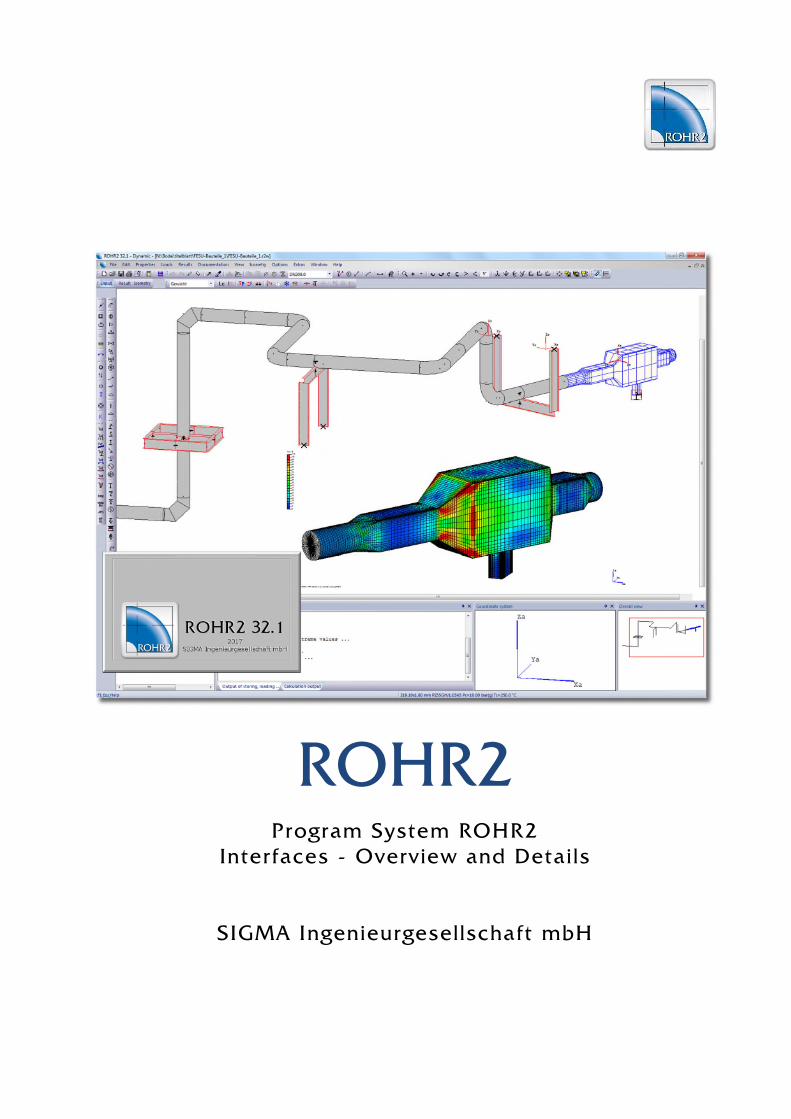
ROHR2Program System ROHR2
Interfaces - Overview and Details
SIGMA Ingenieurgesellschaft mbH


ROHR2 Interfaces Feature List
ROHR2_InterfacesSIGMA Ingenieurgesellschaft mbH www.rohr2.com
Content
ROHR2 Introduction.................................................................................................................................... 1
1 ROHR2 interfaces........................................................................................................................................ 1
1.1 ROHR2 Interfaces overview.......................................................................................................................... 2
1.2 Licenses and system requirements............................................................................................................... 3
2 Interfaces to CAD-Systems ........................................................................................................................ 4
2.1 Neutral CAD Interface ROHR2...................................................................................................................... 5
2.2 Alternative Data formats................................................................................................................................ 6
2.2.1 Interfaces to CAD-Systems........................................................................................................................... 6
2.2.2 Interfaces for the conversion of piping structures.......................................................................................... 8
3 CAE Interfaces............................................................................................................................................. 9
3.1 Pipe stress analysis software interfaces ....................................................................................................... 9
3.1.1 ROHR2 Import .............................................................................................................................................. 9
3.1.2 ROHR2 Export .............................................................................................................................................. 9
3.2 Fluid dynamics interfaces.............................................................................................................................. 9
3.2.1 Pressure loss ................................................................................................................................................ 9
3.2.2 Fluid dynamics ............................................................................................................................................ 10
4 ROHR2 Results Export ............................................................................................................................. 11
4.1 Support data................................................................................................................................................ 11
4.1.1 Export of general support data .................................................................................................................... 11
4.1.2 Manufacturer specific software formats....................................................................................................... 11
4.2 CAD Export ................................................................................................................................................. 12
4.2.1 Export to PDMS/E3D................................................................................................................................... 12
4.2.2 NTR and PCF-Export .................................................................................................................................. 12
4.3 Export of graphics ....................................................................................................................................... 13
5 Third party interfaces................................................................................................................................ 13
Rel.18.04

ROHR2 interfaces Feature listPage 1 - ROHR2 interfaces
ROHR2_InterfacesSIGMA Ingenieurgesellschaft mbH www.rohr2.com
1 ROHR2 interfaces
A comprehensive number of interface modules is part of the ROHR2 standard package.Optional interfaces are available to integrate ROHR2 into your workflow.
This document shows an overview on the interfaces, available with ROHR2 and their application.Please contact us concerning the optimization of your workflow with ROHR2. Our support team would bepleased to provide you with detailed parameter listings and the integration of third party products.
ROHR2 Interfaces, Standard equipment and optional modules
CAD/CAEROHR2 connecting with
Calculation

ROHR2 interfaces Feature listPage 2 - ROHR2 interfaces
ROHR2_InterfacesSIGMA Ingenieurgesellschaft mbH www.rohr2.com
1.1 ROHR2 Interfaces overview
ROHR2 available interfaces - Overview Import /Export
Standard
package
Optionalavailableinterfaces
Neutral Interface ROHR2 with PDMS/E3D dataexchange
IMP X
EXP X
DXF data import IMP X
CSV Geometry data import IMP X
Support data Interface EXP X
LICAD, CASCADE, FLEXPERTE EXP X
PDMS/E3DIMP X
EXP X
ROHR2 - Druckverlust /Fluiddynamik
SINETZ Pressure loss EXP X
Fluid flow calculation, CFD(PIPENET, FLOWNEX, etc.)
IMP X
EXP X
*.FRC Import of Load-time courses, e.g. Flowmaster,AFT Impulse
IMP X
*.CSV Import of Load-time functions, IMP X
ROHR2 – CAE systems transfer
CAEPIPE IMP X
PIPESTRESS IMP X
CAESAR IIIMP X
EXP X
KWUROHR (Siemens) IMP X
ROHR2 CAD interface package, includes
PCF pipe component file (*.pcf) IMP X
EXP X
PDS IMP X
PASCE IMP X
AUTOPLANT/AUTOPIPE PXF IMP X
SDNF (structural steel) IMP X
PLANT3D data IMP X

ROHR2 interfaces Feature listPage 3 - ROHR2 interfaces
ROHR2_InterfacesSIGMA Ingenieurgesellschaft mbH www.rohr2.com
Interfaces in the ROHR2 standard package
The interfaces are part of the standard delivery of ROHR2 Static/Static and Dynamic to be integrated intoROHR2.
Optional Interfaces
Optional interfaces are not part of the standard delivery of ROHR2 Static/Static and Dynamic.
1.2 Licenses and system requirements
Program version, network license
The interfaces are included or optional available modules in the program system ROHR2.They can be part of the ROHR2 single user license and ROHR2 network license. In the ROHR2 networklicense the number of the users of an interface module is always similar to the number of ROHR2 networkseats.The system requirements are similar to those of the ROHR2 program (see ROHR2 Specification).Interfaces are part of the ROHR2 user interface.

ROHR2 interfaces Feature listPage 4 - Interfaces to CAD-Systems
ROHR2_InterfacesSIGMA Ingenieurgesellschaft mbH www.rohr2.com
2 Interfaces to CAD-Systems
The data for generating a pipe model in ROHR2 is done by importing files from 3D Plant engineeringsystems by integrated interfaces (some of them optionally available).
The import process is not working on the basis of simple graphic data but onintegrated component databases or database reports. This enables to getmore information than a simple piping structure, like assignment of materials,dimensions or support positions, required for the modeling in the ROHR2pipe stress calculation ROHR2
The ROHR2 Neutral Interface is the main program module for the integrationof CAD-programs.The import is made by two steps:- transfer into the neutral file format- conversion into the ROHR2 input format.
The neutral interface is part of the current ROHR2 standard package oravailable as an upgrade.
Use the command FILE| OPEN to select one or more files of the same type. A project is generatedcontaining the imported data of all selected files.
Scope of transferred data
Automatic generation of the ROHR2 input data from CAD-systems, in detail (if available): Geometry data Diameter, Wall thickness` Materials Support points and support conditions Tees Instruments, flanges Expansion joints Reducers Design data, operation data
The conversion volume depends on the quantity and quality of the imported data.The quantity and quality of the imported data depends on the capability of the exporting CAD/CAEsoftware. In many times there are opportunities to configure the export capabilities at the source.
Enables automatic generation ofthe load cases dead weight,medium weight and operation.
Stresses and loads can bedetermined according to thecalculation standard.

ROHR2 interfaces Feature listPage 5 - Interfaces to CAD-Systems
ROHR2_InterfacesSIGMA Ingenieurgesellschaft mbH www.rohr2.com
2.1 Neutral CAD Interface ROHR2
To simplify the data interchange with CAD systems, the format of the neutral interface was defined. Beingbased on the listing of all elements in the system (pipe, bend, instruments, supports, ...) it can be createde.g. by a report from a database.For each element parameters required by ROHR2 have to be indicated.Only a part of the parameters must be entered by the user, not indicated parameters are filled withstandard values or calculated from other parameters. The elements are written into an ASCII file as datasets with defined record label and correspondingparameters.
These CAD-Systems are creating data in the format ofthe Neutral interface enabling the direct data import intoROHR2:
AVEVA PDMS/E3D, CADISON (ITF) RC-Planet (Planet GmbH), MPDS4 (CAD Schroer), HICADnext (ISD GmbH), u.a.
The ROHR2 standard package includes the import ofdata in NTR format from AVEVA PDMS/E3D using theROHR2 neutral interface.
On the part of the CAD/CAE system optional modulesmay be required for the generation of an export file inNeutral file format
ROHR2 interfaces Feature listPage 6 - Interfaces to CAD-Systems
ROHR2_InterfacesSIGMA Ingenieurgesellschaft mbH www.rohr2.com
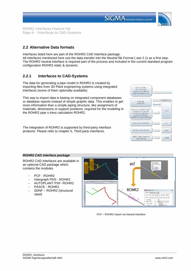
2.2 Alternative Data formats
Interfaces listed here are part of the ROHR2 CAD Interface package.All interfaces mentioned here use the data transfer into the Neutral file Format ( see 2.1) as a first step.The ROHR2 neutral interface is required part of the process and included in the current standard programconfiguration ROHR2 static & dynamic.
2.2.1 Interfaces to CAD-Systems
The data for generating a pipe model in ROHR2 is created byimporting files from 3D Plant engineering systems using integratedinterfaces (some of them optionally available).
This way to import data is basing on integrated component databasesor database reports instead of simple graphic data. This enables to getmore information than a simple piping structure, like assignment ofmaterials, dimensions or support positions, required for the modeling inthe ROHR2 pipe s tress calculation ROHR2.
The integration of ROHR2 is supported by third-party interfaceproducts. Please refer to chapter 5, Third party interfaces.
ROHR2 CAD interface package
ROHR2 CAD interfaces are available inan optional CAD package whichcontains the modules
- PCF - ROHR2- Intergraph PDS - ROHR2- AUTOPLANT PXF- ROHR2- PASCE - ROHR2- SDNF – ROHR2 (structural
steel)
PCF – ROHR2 Import via Neutral Interface
ROHR2 interfaces Feature listPage 7 - Interfaces to CAD-Systems
ROHR2_InterfacesSIGMA Ingenieurgesellschaft mbH www.rohr2.com
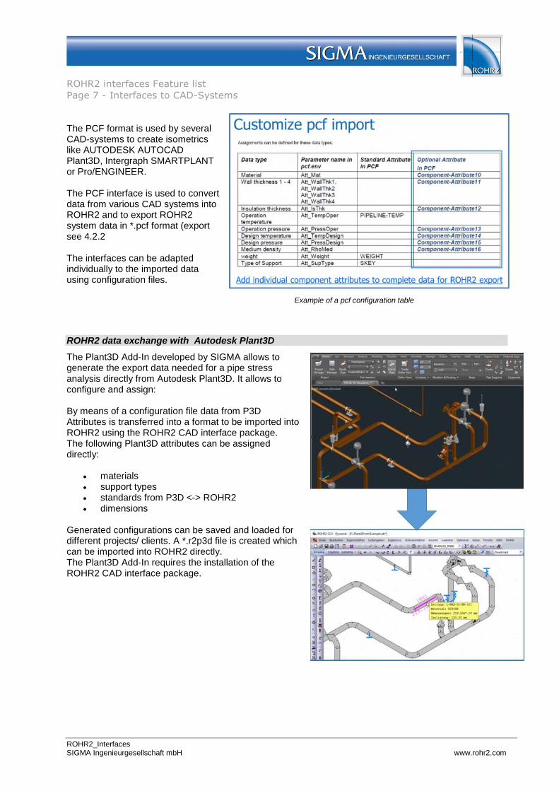
The PCF format is used by severalCAD-systems to create isometricslike AUTODESK AUTOCADPlant3D, Intergraph SMARTPLANTor Pro/ENGINEER.
The PCF interface is used to convertdata from various CAD systems intoROHR2 and to export ROHR2system data in *.pcf format (exportsee 4.2.2
The interfaces can be adaptedindividually to the imported datausing configuration files.
Example of a pcf configuration table
ROHR2 data exchange with Autodesk Plant3D
The Plant3D Add-In developed by SIGMA allows togenerate the export data needed for a pipe stressanalysis directly from Autodesk Plant3D. It allows toconfigure and assign:
By means of a configuration file data from P3DAttributes is transferred into a format to be imported intoROHR2 using the ROHR2 CAD interface package.The following Plant3D attributes can be assigneddirectly:
materials support types standards from P3D <-> ROHR2 dimensions
Generated configurations can be saved and loaded fordifferent projects/ clients. A *.r2p3d file is created whichcan be imported into ROHR2 directly.The Plant3D Add-In requires the installation of theROHR2 CAD interface package.

ROHR2 interfaces Feature listPage 8 - Interfaces to CAD-Systems
ROHR2_InterfacesSIGMA Ingenieurgesellschaft mbH www.rohr2.com
2.2.2 Interfaces for the conversion of piping structures
The creation of a piping model by means of graphics data information (e. g. AUTOCAD *.dwg) allows togenerate a geometry model in best case. ROHR2 does not support this working method, becausemodeling in ROHR2win is the more efficient way to get a piping model.
3D DXF data import
Generate a ROHR2 model from 3D isometrics in in DXF format (*.dxf)All types of lines („LINE“, "POYLINE“, „LWPOLYLINE“) are used to generate ROHR2 segments.Select the layers which need to be considered.
CSV import interface – Reading geometry data from text files
The interface CSV is used to convert data in text format (*.csv - comma separated value) into a formatreadable by ROHR2.
This way piping structures can be generated to get a ROHR2 project piping model. Parameters relevantfor the calculation need to be added in the ROHR2 project.
ROHR2 piping model basing on node coordinates

ROHR2 interfaces Feature listPage 9 - CAE Interfaces
ROHR2_InterfacesSIGMA Ingenieurgesellschaft mbH www.rohr2.com
3 CAE Interfaces
3.1 Pipe stress analysis software interfaces
3.1.1 ROHR2 Import
CAESAR II Interface Import of data from Neutral File Format (*.cii).from Caesar II (Intergraph Corporation)
CAEPIPE Interface Import of data from model batch files (*.mbf) fromCAEPIPE (SST Systems INC.)
PIPESTRESS Interface Import of data from model batch files (*.fre).from PIPESTRESS (DST Computer Services S.A.).
KWUROHR Interface Import of data in format *.kwu data from KWUROHR(SIEMENS)
The interface is used for the data import from pipe stress analysis software.Part of the imported data are the piping model as well as load case parameters.The range of the imported data is documented comprehensively in the interface manuals.
3.1.2 ROHR2 Export
CAESAR II Export interface Export of data into the Caesar II Neutral File Format to beused in Caesar II (Intergraph Corporation)
The interfaces are used for the data export to Caesar II. Part of the imported data is the piping model aswell as load case parameters.For details please refer to the separate manual, which is part of the interface software.
3.2 Fluid dynamics interfaces
3.2.1 Pressure loss
SINETZ Interface Export of calculation models into SINETZ(Product of SIGMA Ingenieurgesellschaft mbH)
The SINETZ program includes a neutral interface to import data from CAD/CAE programs. It enables toimport geometry data, dimensions, insulation, components like bends, instruments, pumps, reducers andorifices as well as boundary conditions (pressure, temperature and quantities).
ROHR2 interfaces Feature listPage 10 - CAE Interfaces
ROHR2_InterfacesSIGMA Ingenieurgesellschaft mbH www.rohr2.com
3.2.2 Fluid dynamics
General Fluid dynamic data exchange
Interface Fluid dynamic programsImport of load - time-functions
Import of fluid hammer forces into ROHR2For the conversion of load-time functions from various fluiddynamic software ROHR2 provides an import capability.ROHR2 converts *.frc and *.csv-files or ASCII files into aproprietary ROHR2 binary format.
The interface is used for the data transfer from software products like PIPENET Flownex DRAKO INROS FLOWMASTER AFT Impulse
Additional program systems upon request
Fluid dynamic systems PIPENET and FLOWNEX
PIPENET and FLOWNEXimport and export interfaces
Interface for the exchange of databetween ROHR2 and fluid dynamicsoftwares
PIPENET (Sunrise Systems Ltd,www.sunrise-sys.com).
FLOWNEX (www.flownex.com).
File transfer and calculation process
The entire ROHR2 model is converted into the format ofthe fluid dynamic system.
At deflections, branches and reductions in the ROHR2model force vectors will be generated, assigned andexported.
The calculation of the time-dependent forces is carriedout in the fluid hammer software.
Load -time functions (dynamic fluid hammer forces) canbe transferred to ROHR2 and assigned automatically
The fluid hammer analysis of the piping framework canbe carried out nearly without additional manual inputs,because the fluid hammer forces have been created bythe fluid analysis programs.
The data exchange uses the file formats*.sdf for PIPENET*.nts for FLOWNEX

ROHR2 interfaces Feature listPage 11 - ROHR2 Results Export
ROHR2_InterfacesSIGMA Ingenieurgesellschaft mbH www.rohr2.com
4 ROHR2 Results Export
ROHR2 offers various data formats for the export of calculation resultsThe number of generated results contains general data as well as particular parameters to be transferredby manufacturer software tools.
4.1 Support data
4.1.1 Export of general support data
Data of all supports may be exported for further treatment. The export file is a fixed-format text fileincluding calculated results. The file extension is *.sup.The interface CSV is used to convert data in text format (*.csv) by ROHR2.
ROHR2 Export Supports
4.1.2 Manufacturer specific software formats
ROHR2 generates individually adapted export files to be used in the CAE systems:: LICAD (LISEGA GmbH) CASCADE und FLEXPERTE (Witzenmann GmbH)
For details of the data conversion please refer to the software documentation
ROHR2 interfaces Feature listPage 12 - ROHR2 Results Export
ROHR2_InterfacesSIGMA Ingenieurgesellschaft mbH www.rohr2.com
4.2 CAD Export
4.2.1 Export to PDMS/E3D
PDMS Interface ROHR2
In addition to the import of PDMS/E3D data (see 2.1, Neutral interface) ROHR2 results can be exportedinto PDMS/E3D.
The data export from ROHR2 to PDMS/E3D includes load case dependent support results anddeformations.Deformed structures may be represented in PDMS this way. Beyond that, in PDMS calculation results arestored for further treatment, e.g. LICAD hanger design software.
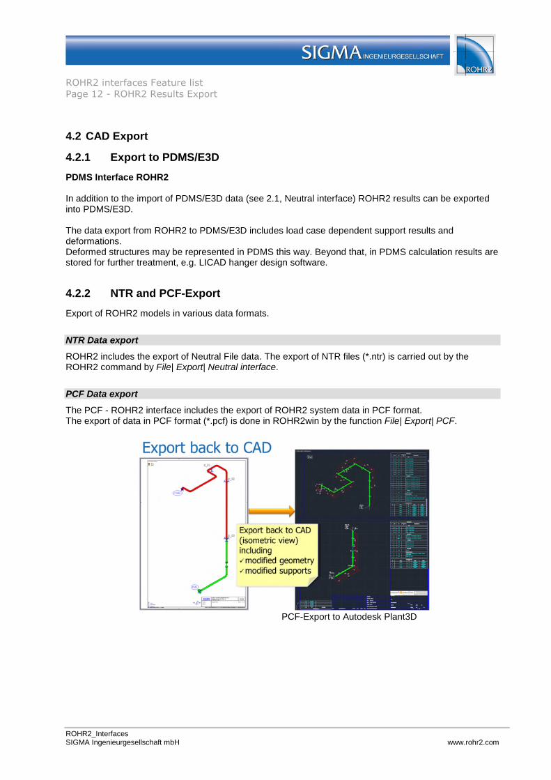
4.2.2 NTR and PCF-Export
Export of ROHR2 models in various data formats.
NTR Data export
ROHR2 includes the export of Neutral File data. The export of NTR files (*.ntr) is carried out by theROHR2 command by File| Export| Neutral interface.
PCF Data export
The PCF - ROHR2 interface includes the export of ROHR2 system data in PCF format.The export of data in PCF format (*.pcf) is done in ROHR2win by the function File| Export| PCF.
PCF-Export to Autodesk Plant3D
ROHR2 interfaces Feature listPage 13 - Third party interfaces
ROHR2_InterfacesSIGMA Ingenieurgesellschaft mbH www.rohr2.com
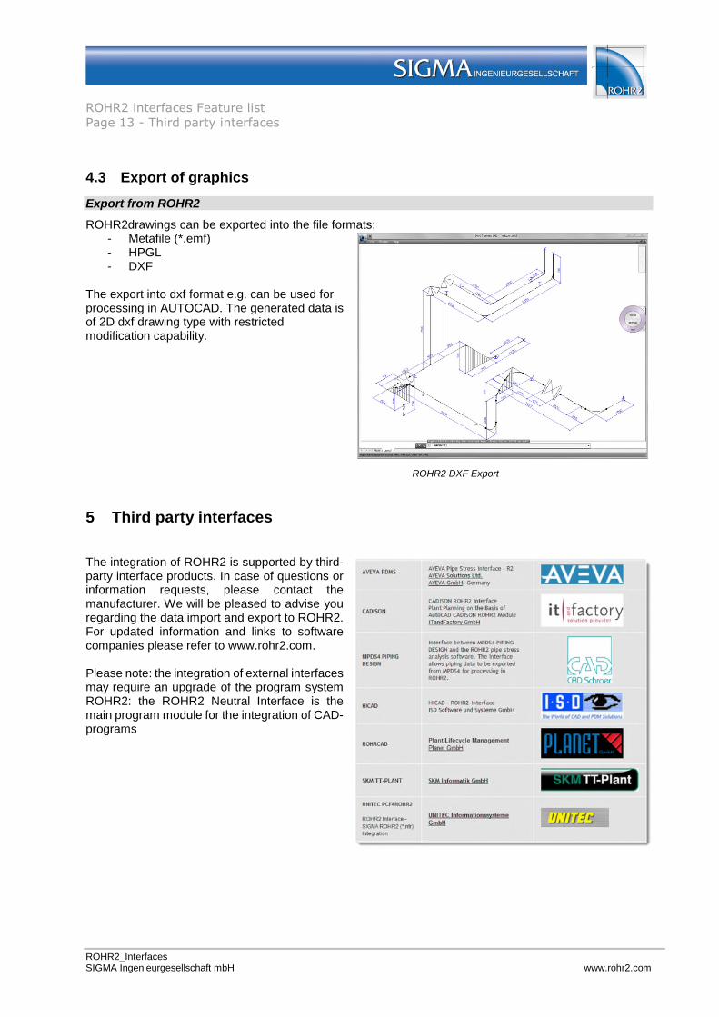
4.3 Export of graphics
Export from ROHR2
ROHR2drawings can be exported into the file formats:- Metafile (*.emf)- HPGL- DXF
The export into dxf format e.g. can be used forprocessing in AUTOCAD. The generated data isof 2D dxf drawing type with restrictedmodification capability.
ROHR2 DXF Export
5 Third party interfaces
The integration of ROHR2 is supported by third-party interface products. In case of questions orinformation requests, please contact themanufacturer. We will be pleased to advise youregarding the data import and export to ROHR2.For updated information and links to softwarecompanies please refer to www.rohr2.com.
Please note: the integration of external interfacesmay require an upgrade of the program systemROHR2: the ROHR2 Neutral Interface is themain program module for the integration of CAD-programs