strength criteria
DESCRIPTION
rock Strength CriteriaTRANSCRIPT

Strength Criteria: Mohr- Coulomb and Hoek- Brown
Introduction to Numerical Modelling Exam Preparation Course (c) OHMS 2011
Describe the difference between
Rock Engineering design
parameters and failure criteria
Design parameters are used by rock engineers as guidelines to
design support, mining layouts etc. These will typically quote a
number or an envelope to be achieved or not to be exceeded.
The design process will typically involve testing various layouts
etc. against the design parameter.
A failure criterion is a methodology that is used to determine
when a rock or an excavation will fail.
Introduction to Numerical Modelling Exam Preparation Course (c) OHMS 2011

Strength (Failure criterion)
• Empirical and attempts to describe the stress environment at failure without necessarily explaining why failure takes place.
Introduction to Numerical Modelling Exam Preparation Course (c) OHMS 2011

Failure Parameters and derivation Failure criterion How it is derived
Hoek Brown Failure Criterion
From tri-axial lab tests or empirical observations
Mohr Coulomb Failure Criterion
From tri-axial lab tests
Coulomb’s Shear Strength Criteria
From lab tests
Barton Brandis
From lab tests and discontinuity surface observations.
Griffiths Failure Criterion
Empirically with formulae
Introduction to Numerical Modelling Exam Preparation Course (c) OHMS 2011

Failure Parameters and application
Failure criterion Application
Hoek Brown Failure Criterion To determine under what stress conditions will failure occur
Mohr Coulomb Failure Criterion To determine under what stress conditions will failure occur
Coulombs Shear Strength Criteria To determine under what stress conditions will shear failure occur
Introduction to Numerical Modelling Exam Preparation Course (c) OHMS 2011

Failure Parameters and application
Failure criterion Application
Barton Brandis Shear Strength Criteria To determine under what stress conditions will shear failure occur
Griffiths Failure Criterion To determine when failure of a solid will occur
Introduction to Numerical Modelling Exam Preparation Course (c) OHMS 2011

Failure parameters and what is derived from it?
Failure criterion What is derived from it
Hoek Brown Failure Criterion Rock mass failure
Mohr Coulomb Failure Criterion Rock mass failure
Coulomb’s Shear Strength Criteria Shear Failure
Barton Brandis Shear Failure
Griffiths Failure Criterion Crack initiation
Introduction to Numerical Modelling Exam Preparation Course (c) OHMS 2011

Mohr Coulomb Criterion
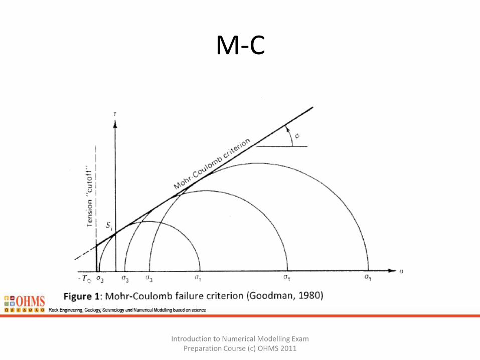
Figure 1 shows tri-axial test results plotted in the form of a Mohr diagram . The Mohr circle is a very convenient way of plotting the principal stresses - the two principal stresses are plotted on the x-axis, and the radius of the circle is the maximum shear
stress (1 - 3)/2. The plot is therefore one of shear stress against normal stress. The Mohr circle plot can be used to determine stress magnitudes at different orientations. As shown in Figure 1, the Mohr-Coulomb shear strength failure criterion is a linear envelope to the Mohr circles. The equation of the line is given by:
Ʈ=Si + tan Since rock is weak in tension, the criterion is incorrect to the left of the ordinate axis, and a tension cut off is usually used, as shown in Figure 1.
Introduction to Numerical Modelling Exam Preparation Course (c) OHMS 2011
M-C
Introduction to Numerical Modelling Exam Preparation Course (c) OHMS 2011
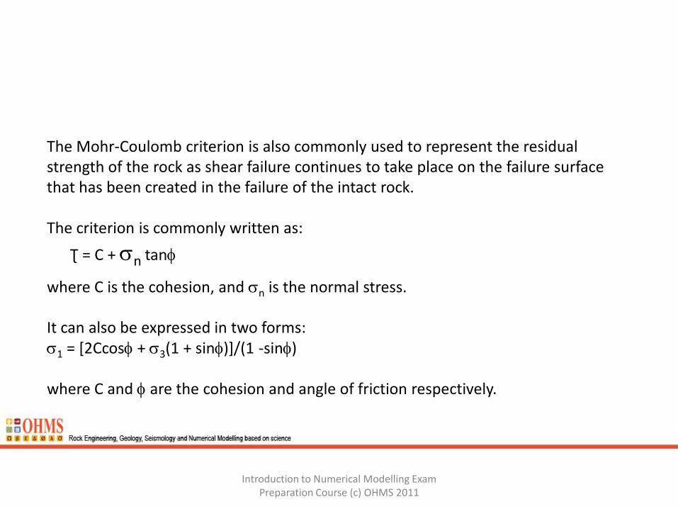
The Mohr-Coulomb criterion is also commonly used to represent the residual strength of the rock as shear failure continues to take place on the failure surface that has been created in the failure of the intact rock. The criterion is commonly written as:
Ʈ = C + n tan
where C is the cohesion, and n is the normal stress. It can also be expressed in two forms: 1 = [2Ccos + 3(1 + sin)]/(1 -sin) where C and are the cohesion and angle of friction respectively.
Introduction to Numerical Modelling Exam Preparation Course (c) OHMS 2011

Since:
c = 2Ccos/(1-sin)
then first equation can be rewritten as:
1 / c = 1 + C. 3/ c.
where C = (1 + sin)/(1 -sin) and c is the UCS.
The orientation of the predicted shear failure plane is (45 + /2) degrees, where this angle is measured in the 1-3 space from the 3 axis.
Introduction to Numerical Modelling Exam Preparation Course (c) OHMS 2011

It is difficult to judge the appropriate location of an tangent line (envelope) to Mohr circles especially when it does not clearly define a straight line envelope.
It is easier to plot the results in the form of an apex point plot, as shown in Figure 2, or a 1 vs 3 graph, as shown in Figure 3.
The cohesion and friction values can also be obtained from these graphs.
Introduction to Numerical Modelling Exam Preparation Course (c) OHMS 2011

Figure 2
Introduction to Numerical Modelling Exam Preparation Course (c) OHMS 2011
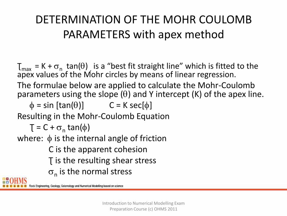
DETERMINATION OF THE MOHR COULOMB PARAMETERS with apex method
Ʈmax = K + n tan() , is a “best fit straight line” which is fitted to the apex values of the Mohr circles by means of linear regression. The formulae below are applied to calculate the Mohr-Coulomb parameters using the slope () and Y intercept (K) of the apex line. = sin [tan()] C = K sec[] Resulting in the Mohr-Coulomb Equation Ʈ = C + n tan() where: is the internal angle of friction C is the apparent cohesion Ʈ is the resulting shear stress n is the normal stress
Introduction to Numerical Modelling Exam Preparation Course (c) OHMS 2011

Figure 3 : 1 vs 3 plot for norite
Introduction to Numerical Modelling Exam Preparation Course (c) OHMS 2011

M-C Limitations
The Mohr-Coulomb criterion is not a particularly satisfactory criterion for rock, since : • it implies that a major shear fracture occurs at peak strength. The criterion is likely to give incorrect results if the failure mechanism is not shear. • it implies a direction of shear failure which often does not agree with observations, particularly in brittle rock; • it is linear and peak strength envelopes determined experimentally are usually non-linear, as shown in Figure 4 below. •It assumes that friction and cohesion are acting in unison •It will be noticed that only or 1 and 3 are used and that 2 is ignored in this criterion.
Introduction to Numerical Modelling Exam
Preparation Course (c) OHMS 2011

Introduction to Numerical Modelling Exam Preparation Course (c) OHMS 2011

Hoek-Brown failure criterion Hoek and Brown developed an empirical criterion for rock and rock mass failure based on tests on intact rock and on rock mass models (Hoek et al, 2002). The generalised form of the Hoek-Brown failure criterion is:
where
mb is the Hoek-Brown constant m for the rock mass, s and a are constants which depend on the rock mass characteristics . ci is the UCS of the intact rock
Introduction to Numerical Modelling Exam Preparation Course (c) OHMS 2011

For intact rock, the above equation simplifies to
To use the Hoek-Brown criterion for intact rock it is necessary to know values for m, and ci . Laboratory determined values of m, for a range of rock types are shown in Figure 5 (in this figure, the whiskers show the range of test results, the box the upper and lower quartiles, and the bar the median value). For rock masses, rock mass classification values are required as well, from which mb, s and a can be calculated from the equations below (Hoek et ai, 2002).
mb = mi exp{(GSI - 100)/(28 - 14D)}
s = exp{(GSI - 100)/(9 - 3D)}
a = ½ + {exp(-GSI/15) - exp(-20/3)}/6
Introduction to Numerical Modelling Exam
Preparation Course (c) OHMS 2011

Introduction to Numerical Modelling Exam Preparation Course (c) OHMS 2011

H-B Limitations
•The Hoek-Brown criterion is also a shear based criterion and therefore has similar limitations to the Mohr-Coulomb criterion. •Only 1 and 3 are used and 2 is ignored. •It also only applies to the "central" range of rock masses, ie well-jointed rock masses in which the joints control behaviour rather than the rock material or individual significant planes of weakness. •In brittle rock failure will initially develop as damage of the rock, followed by spalling failure and then ultimately transition to shear failure. The criterion has recently been modified to cater for both high strength brittle rock conditions and low strength weak ground conditions. The modified relationships are shown below.
Introduction to Numerical Modelling Exam Preparation Course (c) OHMS 2011

Introduction to Numerical Modelling Exam Preparation Course (c) OHMS 2011

Extension strain criterion
The extension strain criterion (Stacey, 1981) is a simple criterion which appears to work quite well for brittle massive rocks. It automatically takes into account the three dimensional stresses. The minimum principal strain may be negative (extension) as a result of the stresses acting, and the criterion simply states that fracture of the rock will initiate when the extension strain exceeds a certain value characteristic of the rock.
The minimum principal strain is calculated from the three dimensional strain-stress relationship:
3 = [3 – v(1 +2)]/E
For failure, the criterion is:
3 cr , where cr is the critical value of extension strain.
Introduction to Numerical Modelling Exam Preparation Course (c) OHMS 2011

End Session 1.4
Strength Criteria
Introduction to Numerical Modelling Exam Preparation Course (c) OHMS 2011