street lighting specification - home - durham … · 25 cable laying 25 26 ... street lighting...
TRANSCRIPT
Revised Specification 22nd December 2014
Final
Neighbourhood Services
Technical Services, Strategic Highways - Assets Street Lighting
STREET LIGHTING INSTALLATIONS
For Lighting on New Residential Roads and Industrial Estates
STREET LIGHTING SPECIFICATION
Terry Collins Director of Neighbourhood Services
County Hall Durham DH1 5UQ December 2014
Specification for Street Lighting
Section 38/278 Agreements
Index
Page 1. General Requirements 1 2 Planning & Programming 5 3 Prospective Residents Liaison 5 4 Siting of Equipment 6 5 Adoption of Lighting 6 6 Design Standards 7 9 Energy Conservation 9 10 Legislation, Regulations, Codes and Specifications 10 11 Obtrusive Light 11 13 Equipment (General) 12 14 PECU’s 12 15 Luminaires 13 16 LED’s & LED Drivers 15 17 General Specification 16 18 Columns & Brackets 19 19 Corrosion Protection for Steel Columns and Brackets 22 20 Light Sources 22 21 Clear Cut-Outs 23 22 Fuses 24 23 Cables 24 24 Cable Ducts 25

25 Cable Laying 25 26 Erection of Columns & Brackets 25 27 Internal Wiring 26 28 Illuminated Traffic Signs 26 29 Electricity Supply Services 27 30 Earthing 28 31 Painting 28 32 Electric Testing & Commissioning 86 Appendices 1,2,3,4 Typical Wiring Arrangements 30 to 33 5 Lighting Column Standard Foundation 34 6 Pedestrian Refuge Signs Standard Detail 35 7 Electrical Test Report Forms 36 & 37 8 DCC Scheme Approval Check List 38

Page | 1revision-23-12-2014
Street Lighting Specification for Street Lighting
Residential and Industrial Estates
1. General Requirements 1.1 This specification is intended as a guide and it must be borne in mind by the
developer that any and all proposals put forward are subject to approval by the Street Lighting Manager for Durham County Council, Neighbourhood Services, and Strategic Highways Assets. All proposals must conform to this specification.
1.2 Prior to site works of any kind the developer must contact the Director of Neighbourhood Services, Strategic Highways Assets Street Lighting Section to determine if any works are required to maintain electrical supplies to existing street lighting or illuminated street furniture within or in the vicinity of the site.
1.3 The developer shall provide an approved form of street lighting as an integral part of the estate development. Proposals for street lighting must be included with the drawings and specifications and be submitted for approval to the Director of Regeneration and Economic Development. The proposals shall include the positions of lighting columns, type of columns, lanterns, cables, cable routes and proposed Electricity Company Northern Power Grid or Independent Distribution Network Operator service connections;. Two copies of each drawing shall be provided. In addition an Auto-cad (DWG) drawing shall be e-mailed to the Director of Neighbourhood Services, Strategic Highways Assets Street Lighting Manager at [email protected] or the appropriate officer, together with a copy of the design data showing proposed illumination levels. On the roads and footpaths/ footways to be lit including the cable design calculations where appropriate. “Fees for checking standard of lighting design are taken from the supervision fees included in the Section 38 agreement. However, where designs are complex or involve major changes to the existing lighting system, additional fees may be required and this will be identified to the developer/consultant at the time. Additional fees may be required if a single submission is submitted without the required changes on more than two occasions, again these will be identified to the developer/consultant the time.”
1.4 Consultation
1.5 It is important for the consultant or developer to consult with the local authority advising that the unmetered supply connections will be fed from and IDNO network. Any questions, technical queries and advice needed can be addressed at the design stage and before the site works commence.
1.6 Highway Electrical Equipment and Connections Design
1.7 Early exchange of information can help reduce delays, variations and hence costs.
Page | 2revision-23-12-2014
1.8 Highway Electrical designs - eg street lighting designs should be approved by
Durham County Council and information exchanged between the developer, adopting authority and distribution network operator that will provide the electricity connections.
1.9 Where possible the design of street lighting installations should be included with the developer’s plot layout. Electricity mains can be designed a routed in such a way that the positioning of street lighting columns can be optimised to reduce costs at the outset.
1.10 Connection Arrangements
1.11 Street lighting connections will normally be via single connections to each column or where specified by the local authority, a single point of connections will be provided to a control point.
1.12 IDNO’s will tend to work at national level across the UK and therefore, there will be a requirement to maintain a consistent connection arrangement for each point of supply.
1.13 IDNO’s will utilise ‘Waveform’ CNE mains cables with a CNE service cable terminated into a street lighting clear cut-out offering a PME earth terminal where possible. IDNOs will endeavour to meet the requirements of adopting local authority regarding their requirements for looped services, agreement should from the IDNO prior to the installation of such services.
1.14 Secondary double pole isolation should be provided above the distribution network operator’s clear cut-out and the owner of the street lighting equipment in accordance with the local authority’s specification.
1.15 The IDNO/DNO will terminate the cable into the IDNO/DNO clear cut-out and energise the short tails to the column by insertion of a fuse into the clear cut-out after completing the necessary insulation resistance, polarity and earth loop impedance checks, but will leave the fuse withdrawn from the secondary isolation.
1.16 Where a competent person is on site and can provide certificates of satisfactory tests then the columns can be energised by that competent person.
1.17 Street Lighting Inventory
1.18 Details of the street lighting equipment should be supplied by the developer with the street lighting connections application.
1.19 Details of the street lighting equipment should be submitted to the IDNO to establish the unmetered supplies certificate (UMS) by either the developer.
1.20 The Local Authority will need to include the adopted street lighting equipment in their inventory system. The LA inventory will be capable of clearly identifying items
Page | 3revision-23-12-2014
connected to different DNO networks (where there is more than one DNO in a given authority area) as well as multiple INDN networks. This will enable the LA to contact the IDNO or DNO to report faults (eg loss of supply or damage to the asset).
1.21 The LA will need to submit a separate detailed inventory of equipment to the Unmetered Supplies Operator (UMSO) for each IDN and DNO operating in the LA area at the frequency agreed in the respective connection agreements. The format of the detailed inventory would be as defined in section 4 of the Unmetered Supplies Operational Information document produced by Elexon.
1.22 Unmetered Supply Operator (UMSO)
1.23 Each UMSO will prepare a summary of the inventory and send it to the LA’s Meter Administrator who will then calculate the half hourly and non-half hourly consumptions for the LA who has chosen to purchase their energy. The Meter Administrator will run separate equivalent meters for each DNO/IDNO network.
1.24 Meter Point Administration Number (MPAN)
1.25 The distribution network operator provides a Meter Point Administration Number (MPAN) which represents a reference point for billing purposes. There will be a different MPAN issued to the LA for each distribution network operator.
1.26 The LA will be required to submit each Mpan to the energy provider for registration and they will receive separate bills for each MPAN. The LA may choose to treat lighting units on IDNO networks as non-half hourly or half hourly.
1.27 The Energy Supplier
1.28 The developer or LA cannot purchase energy from the distribution network operator. The developer or LA can continue to purchase energy independently in a competitive mark and use the distribution network operator to transport that the energy. A supplier must be nominated before connection is made. The developer or LA nominated supplier would bill the customer as normal.
1.29 Section 38 Agreements should not discriminate between and incumbent host DNO and an IDNO.
1.30 The Meter Administrator
1.31 The Meter Administrator (MA can remain the same; the only change is that there is an alternative name to the incumbent DNO on the inventory cross referenced to a different MAPAN. The appropriate approach will depend on the commercial arrangement between the LA and their MA.
1.32 Duos Charges
1.33 Distribution Use of System (Duos) charges are published in the individual IDNO/DNO Duos Charging Statement which is approved by OFGEM. Duos charges
Page | 4revision-23-12-2014
are charged to the supplier and remain unchanged between the DNO and embedded IDNO network.
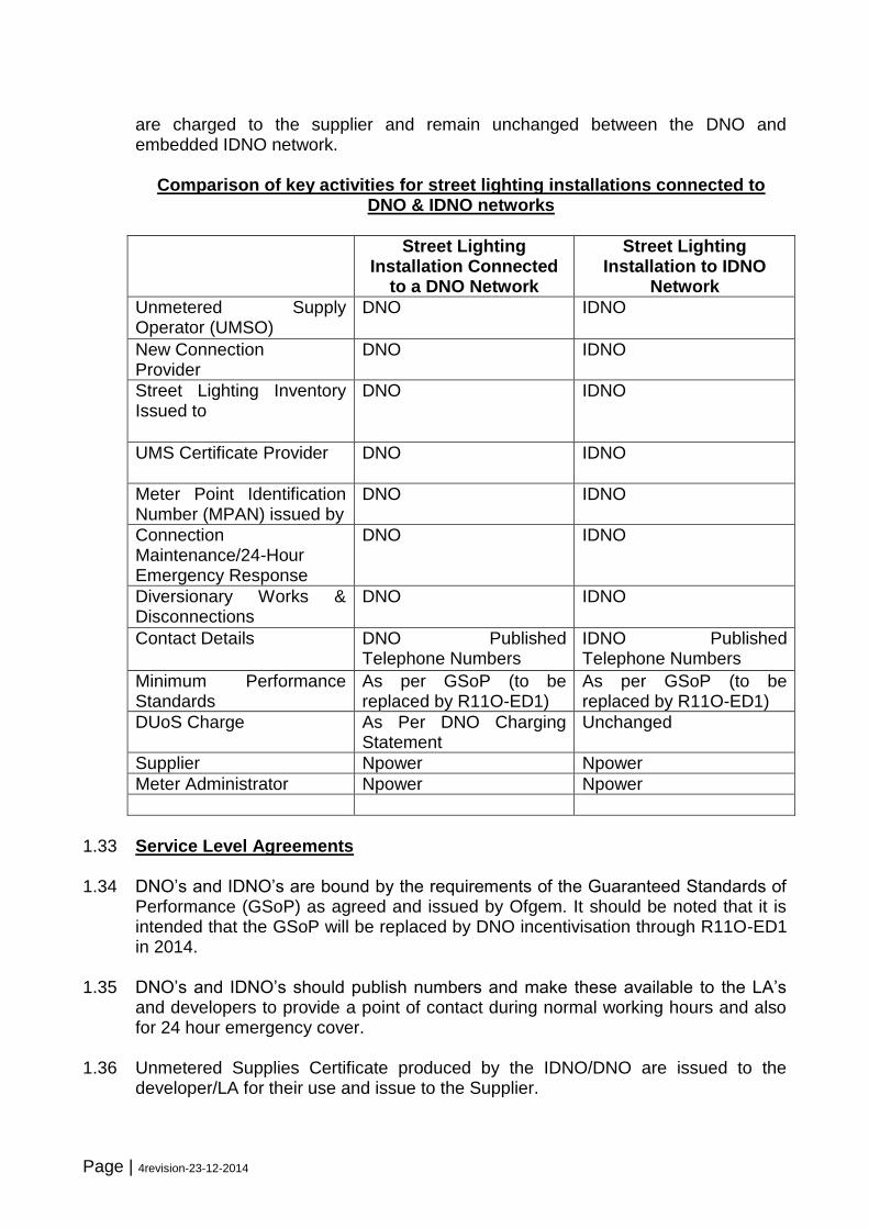
Comparison of key activities for street lighting installations connected to DNO & IDNO networks
Street Lighting Installation Connected
to a DNO Network
Street Lighting Installation to IDNO
Network
Unmetered Supply Operator (UMSO)
DNO IDNO
New Connection Provider
DNO IDNO
Street Lighting Inventory Issued to
DNO IDNO
UMS Certificate Provider DNO IDNO
Meter Point Identification Number (MPAN) issued by
DNO IDNO
Connection Maintenance/24-Hour Emergency Response
DNO IDNO
Diversionary Works & Disconnections
DNO IDNO
Contact Details DNO Published Telephone Numbers
IDNO Published Telephone Numbers
Minimum Performance Standards
As per GSoP (to be replaced by R11O-ED1)
As per GSoP (to be replaced by R11O-ED1)
DUoS Charge As Per DNO Charging Statement
Unchanged
Supplier Npower Npower
Meter Administrator Npower Npower
1.33 Service Level Agreements
1.34 DNO’s and IDNO’s are bound by the requirements of the Guaranteed Standards of
Performance (GSoP) as agreed and issued by Ofgem. It should be noted that it is intended that the GSoP will be replaced by DNO incentivisation through R11O-ED1 in 2014.
1.35 DNO’s and IDNO’s should publish numbers and make these available to the LA’s and developers to provide a point of contact during normal working hours and also for 24 hour emergency cover.
1.36 Unmetered Supplies Certificate produced by the IDNO/DNO are issued to the developer/LA for their use and issue to the Supplier.

Page | 5revision-23-12-2014
1.37 Emergency Response
1.38 DNO’s and IDNO’s have a duty to respond to emergencies, provide maintenance
services and to provide new connections/disconnections whilst recovering its reasonable charges in doing so.
1.39 The approved drawings will be used on any subsequent adoption inspections, therefore, any changes made to road or lighting layout should be re-submitted for approval.
1.40 The drawing indicating the proposed lighting and electrical layout should indicate a clear concise boundary line to identify the limit of adoption (footpaths/ footway and roadway).
1.41 Where new accesses are formed onto existing highways/ footways, or alterations to existing accesses, a conflict area is created. The developer shall be responsible for the provision of new lighting or alterations to existing lighting to the relevant standards.
1.42 Cabling and Servicing – Generally Electricity Company low voltage electrical service connections from their mains system (type Ref: TS/57 manufactured by Tofco/Lucy) double pole clear cut-outs but in the absence of such mains an underground loop in/out system of cabling.
2.00 Planning and Programming 2.1 The developer shall plan all lighting works in conjunction with Durham County
Council’s Street Lighting Policies (available on DCC website at http://www.durham.gov.uk/article/2380/Street-lighting) and standards relating to developments. The developer shall provide Durham County Council a copy of the working programme indicating installation works including any revisions thereto.
3.00 Prospective Residents Liaison 3.1 The developer shall show all lighting units and other illuminated equipment (signs
and bollards) on all construction/layout plans (including sales and legal/ conveyancing literature) in order that prospective residents are aware that there may be equipment placed adjacent to any given plot or property. Durham County Council will not involve itself in any dispute between the developer and prospective resident. Neither will Durham County Council entertain any request to move or alter any equipment arising from any such dispute arising from the developer not appraising the prospective resident of the proximity of any equipment in relation to a plot or property.
Page | 6revision-23-12-2014
3.2 Not Adopted’ Signs to be erected 3.3 On all lighting units and lit signs erected as part of the development (whether On-
site or Off-site), the developer shall attach, via non-metallic cable ties, one ‘Not Adopted’ sign. These signs shall be attached to the lamp columns on erection and remain until such time that the County Council adopts the equipment. The signs shall generally face the carriageway. The pattern and legend of this sign shall be approved by Durham County Council but the purpose is to advise residents to whom they should refer any lighting defect or any other enquiry. On a large development (consisting of more than one new road) Durham County Council would advise the developer to erect an informative sign at the entrance to the site advising residents of contact details for all maintenance purposes. It is essential that the sign shall have accurate contact information for the developer or his agent.
4.00 Siting of Equipment 4.1 All street lighting and associated cable works and ancillary equipment shall only be
installed within the area of the estate which it is proposed will be adopted as highway. In exceptional circumstances, and with the prior approval of the Director of Neighbourhood Services, the developer may be permitted to site apparatus outside the highway if appropriate easements are granted to the County Council at the developer’s expense.
4.2 Columns must not obstruct footpaths or vehicular accesses. They shall be sited in
accordance with BS5489-1:2013 + A2:2008, Code of Practice for the design of road lighting part 1: Lighting of roads and public amenity areas and generally be planted in the footpath at the rear or in the absence of a footpath, a minimum of 0.8 metres from the kerb edge to the face of the column and within the highway to be adopted. No obstruction or planting shall hinder access to the column base compartment or the light distribution from the lantern
5.00 Adoption of Lighting 5.1 Every lighting unit and underground cable, on completion and before being
energised shall be inspected and tested to verify that the requirements of BS 7671 (Current Edition of the IEE Wiring Regulations) have been met. The inspection and the test results shall be submitted to the Director of Neighbourhood Services no later than the time of requesting a Part 2 adoption inspection
. 5.2 It is the developer’s responsibility to obtain an Meter Point Administration
Number (Mpan) from Northern Power Grid or Independent Distribution Network Operator. When requesting underground services for the lighting installation from the electricity company. The developer will then be charged for the energy consumed by the street lighting installation from the date of connection up to and including the date of the final adoption certificate.
5.3 Durham County Council Application for Electrical Supply Methodology shall be applied when applying for electrical connection.

Page | 7revision-23-12-2014
5.4 The developer shall be responsible for the maintenance (including replacement of damaged columns and the like) of the new equipment and any existing equipment affected by the works from the date of commencement of works up to and including the date of the final adoption certificate.
5.5 Upon completion of the installation ‘as constructed’ drawings shall be forwarded to the Director of Neighbourhood Services showing column positions, cable routes, depths, sizes and positions, and service positions and centrally managed systems.
5.6 On request from the developer for formal adoption of the development the lighting
installation will be inspected and any remedial works shall be highlighted. The developer shall be responsible for any remedial repairs together with a bulk lamp change and clean prior to a final adoption certificate being issued. In addition, dependent upon the age of the installation, the developer may be required to re-test/ re-paint the installation at his own expense.
5.7 As soon as possible after the date of the final adoption certificate the developer shall remove ‘Not Adopted’ signs.
6.00 Design Standards 6.1 All public lighting provided on the adopted highway shall be designed and installed
in accordance with BS5489-1:2013 + A2:2008,Code of Practice for the design of road lighting part 1: Lighting of roads and public amenity areas and BSEN 13201-2:2003, BS5489-2-2003, part 2 Lighting of Tunnels, PD CEN/TR 13201-1-1:2004 Selection of Lighting Classes, BS EN 13201-3:2003 Calculation of Performance, BS EN 13201-4:2003 Methods of Measuring Lighting Performance and BS 5489 Guide to General Principals.,
6.2 The actual level of public lighting to be provided shall be in accordance with BS5489 2013 P6, however, P4 shall be provided in areas considered of high crime.
6.3 Deviation from Standards shall only be allowed with prior approval by the Director of Neighbourhood Services.
6.4 In some areas of County Durham the provision of public lighting shall comply with Local Strategies that have been developed, for example Durham City Vision, Bishop Auckland Town Centre Lighting Strategy, and Barnard Castle Vision.
6.5 The Institution of Lighting Professionals ‘Guidance Notes for the Reduction of Obtrusive Light’ recommendation for zoning of areas shall be used when assessing lighting requirements.
6.6 Zone E1 – National Parks, Areas of Outstanding Natural Beauty, Sites of Special Scientific Importance and other Dark Area.
6.7 Villages and settlements within a Zone E1 area shall only be provided with lighting when requested by the Parish Council or residents and then limited to strategic
Page | 8revision-23-12-2014
locations such as telephone boxes, bus stops etc. Lighting shall be restricted to CEN Luminous Intensity Class G4/5 if possible otherwise Class G2/3, as specified in Table A1 of luminous intensity classes in EN 13201-2:2003 Annex A.
6.8 In Zone E1 areas outside villages and settlements shall only be provided with lighting where there is a known night time safety problem which cannot be controlled by other methods such as reflective studs, signing etc. New lighting installations shall be provided to the minimum level proposed by the Standard and be full cut off, CEN Luminous Intensity Class G6. Consideration shall be given to dimming or switching to reduce or vary lighting levels.
6.9 Zone E2 - Areas of Low District Brightness (Rural Location outside Zone E1)
7.0 Villages and settlements within a Zone E2 area shall generally be provided with lighting in accordance with the relevant standard applicable to the type and use of the highway. Consideration shall also be given to the lighting of footpaths and cycle tracks with high night time use. Further details on the lighting of cycle tracks are available in the Institution of Lighting Professionals Technical Report No 23, Lighting of Cycle Tracks, 1998. However, where a cycle track or footpath is remote from a highway or properties and an existing alternative lit route exists, regard should be given to whether it is safe to attract people on to isolated areas by the provision of lighting. Lighting shall be CEN Luminous Intensity Class G4/5 if possible otherwise Class G2/3.
7.1 On roads between villages and settlements in Zone E2 areas lighting shall only be
provided where there is a known night time safety problem which cannot be controlled by other methods. New lighting installations shall be provided to the minimum level recommended by the Standard and be CEN Luminous Intensity Class G6.
7.2 Roundabouts are areas of high traffic conflict and are therefore generally provided with a system of lighting. Rural roundabouts in Zone E2 areas shall be provided with a system of lighting to the minimum level recommended by the Standard and be CEN Luminous Intensity Class G6.
7.3 It may be possible to provide adequate lighting for the safety of the motorist in such locations by means of a single centrally mounted lighting column instead of a proliferation of lighting columns around the perimeter of the roundabout. The height of the column shall be kept to the minimum but adequate to ensure that the whole of the carriageway around the island is correctly illuminated.
7.4 Complex junctions in Zone E2 areas shall only be lit when it can be shown that there is a significant night time traffic flow and no alternative remedial safety actions are effective. New lighting shall be provided to the minimum level recommended by the Standard and be limited to the minimum area necessary for road safety. Careful consideration shall be given to the height and number of columns and to the wattage of the lamp used. New lighting shall be CEN Luminous Intensity Class G6.
Page | 9revision-23-12-2014
7.5 Care shall be taken where there is a cycle track or footpath adjacent to a lit roundabout, lit complex junction or lit rural road to ensure that any conflict points where cyclists, pedestrians and motorists meet or cross are adequately illuminated.
7.6 Areas of special environmental interest in Zone E2 areas shall be subject to an individual assessment to determine the benefits or otherwise of providing a system of street lighting.
7.7 Consideration shall be given to dimming or switching to reduce or vary lighting levels
7.8 Zone E3 - Areas of Medium District Brightness (Urban Location)
7.9 Within an urban location all highways shall be lit in accordance with the relevant standard applicable to the type and category of the highway. (a) Primary Routes (b) District Distributors (c) Local Distributors (d) Access Roads (e) Shared Access Roads (f) Secondary Access Roads
8.0 Category a) b) and c) roads will mainly be classified as traffic routes and shall be lit accordingly. Glare shall be restricted to CEN Luminous Intensity Class G2/3 but Class G4 used if possible.
8.1 Category d) e) and f) roads will generally be considered as residential and lit accordingly. Glare shall be restricted to CEN Luminous Intensity Class G2/3.
8.2 Consideration will also be given to the lighting of footpaths and cycle tracks with high night time use. However, where a cycle track or footpath is remote from an adjacent highway or properties and an existing alternative lit route exists, regard shall be given to whether it is safe to attract people on to isolated areas by the provision of lighting. Glare shall be restricted to CEN Luminous Intensity Class G2/3.
8.3 Areas of special environmental interest in an urban area would normally be lit subject to an individual assessment to determine the benefits or otherwise of providing a system of street lighting at such locations and to assess any environmental restrictions on the type and level of lighting to be provided.
9.0 Energy Conservation
9.1 At the 1992 Earth Summit in Rio, the developed Countries agreed to voluntarily
reduce emissions of greenhouse gases to 1990 levels by the year 2000.
9.2 At the Climate Change Convention in Kyoto in 1997, the developed Countries were legally committed to reduce greenhouse gases affecting the environment.
Page | 10revision-23-12-2014
9.3 The UK Government set a target of reducing carbon dioxide emissions by 12.5% on
1990 levels by the year 2010, however, the corporate target is 40% by 2015
9.4 Lighting systems shall be capable of dimming to allow the Strategic Highways Authority to control such systems to reduce C02 and energy and therefore, meet the corporate requirements as detailed above.
9.5 The County Council has an obligation to comply with the Carbon Management Act and reduction of the baseline of 18% for street lighting and the Carbon Reduction Commitment.
9.6 Energy efficient equipment shall be used at every opportunity and investigations and monitoring of technological developments undertaken.
9.7 The advent of electronic ballasts with reduced energy consumption, near unity
power factor, and ability to be used in a lamp dimming mode shall be specified when appropriate.
9.8 The use of lower wattage white light sources such as CDM-T, PL compact
fluorescent, CPO, and LED (Light Emitting Diodes) shall be considered as research is being conducted to show that lower levels of lighting can be provided using white light to achieve the same visual appearance and reduction of energy and maintenance.
10.0 Legislation Regulations, Codes and Specifications 10.1 All materials used and work done shall comply with all relevant Acts and current
Statutory and other Regulations (including those of the Department for Transport), Codes of Practice, British Standards Specifications and European Standard Specifications and particularly the Institution of Electrical Engineers “Regulations for Electrical Installations”, The New Roads and Street Works Act 1991, The Traffic Signs Regulations and Directions 1994, the Traffic Safety Code for Roadwork’s, Chapter 8 of the Traffic Signs Manual and all successive or amending legislation or regulation.
10.2 All public lighting systems installed and maintained should fully comply with the
following Legislation and Regulations:
Highways Act 1980
Goods and Services Act
The Local Government Contract Act
The Management of Health and Safety at Work Regulations 1982
Electricity at Work Regulations 1989 (in force 1990)
Traffic Signs Regulations and General Directions 1991
Disabled Persons Act 1981
Road Humps Regulations 1990
New Roads and Street Works Act 1991
Page | 11revision-23-12-2014
BS 7671: Regulations for Electrical Installations 1992
BS 5489: Parts 1 – 10 ‘Code of Practice for Road Lighting’
BS EN 60529: ‘Specification for Clarification of Degrees of Protection provided by Enclosures’
BS EN 60598 – 2-3: 1994, Luminaires for Road and Street Lighting
BS5649: ‘Lighting Columns’
BS EN 40-1;1992 Lighting Columns. Definitions and Terms
BS EN.40-2: 2004 Lighting Columns. General Requirements
BS EN 40-1:191, EN 1990, EN 1991-1-4-2005 & 40-3-1-2000 Design and Verification for characteristic loads.
BS.EN 40-3-2:2013 Lighting Columns. Designs and Verification. Verification by Testing
BS 40-3-3:2013 Lighting Columns. Design by Verification. Verification by Calculation
BS 40-5-2002 Lighting Columns. Requirements for Steel Columns
BS 40-6:2002 Lighting Columns. Requirements for Aluminium lighting columns
BS 5469-5:1982, EN 40-5:1982 Lighting Columns. Specification for base compartments and cableways
BS.6547:2004+A1:2009 Guidance for the use of BS 40-3-1 and BS EN 4-3-3
BS EN 12697-40:2012 Bitumous Mixtures. Test methods for hot mix asphalt. In situ drain ability
BS EN 12767 Passively Safe Street Lighting and Sign Posts
Department of Environment, Transport and the Regions Departmental Standard BS26/99 – ‘Design of Lighting Columns’
The Wildlife & Countryside Act (1981) (as amended)
the Conservation (Natural Habitats, etc) Regulations 1994 (as amended)
Department of Environment, Transport and the Regions Advice Note TA 49/07 – ‘Appraisal of New and Replacement Lighting on Trunk Roads and Trunk Road Motorways’
Passively Safe Road BS EN12767 and Institution of Lighting Professionals Technical Report TR30, and Durham County Council Street Lighting Policy.
11.0 Obtrusive Lighting
11.1 Obtrusive light is lighting, which falls outside the area to be illuminated, which can
cause discomfort, annoyance, distraction, or reduces the ability to see. Obtrusive light is referred to as light pollution which can be divided into three main categories:
a) Sky Glow Glare
b) Light trespass
The obtrusive light should be restricted by:
a) The control of the type of light source
Page | 12revision-23-12-2014
b) Restricting the level of light emitted at high angles between 70 and 90 degrees
c) The use of full horizontal cut off (flat glass) luminaries where appropriate 11.2 Attention is drawn to the ILP Guidance Notes for the reduction of Light Pollution,
which includes the recommendation that for road lighting installations, light near to and above the horizontal should be minimised. The use of full horizontal cut off
luminaries at 0uplift will minimise visual intrusion within the landscape as well as upward light. In urban situations luminaries fitted with shallow bowls provide good control of light near to and above the horizontal.
11.3 Within urban locations in areas of medium district brightness glare should be
rectified by the use of lanterns with a CEN luminous intensity class of 2 or 3
12.0 Equipment (General) 12.1 Urban Traffic Routes, Main Distributor Roads – Generally 10 metre mounting height
column supporting LED luminaires as appropriate to meet the requirements for the appropriate ME lighting class.
12.2 Industrial Estate, Local Distributor and Access Roads – Generally 8-10 metre
mounting height column supporting LED luminaires to meet the requirements for the appropriate lighting class.
12.3 Residential Roads Access Roads and Footpaths – Generally 6 metre mounting
height column supporting LED/ as appropriate to meet the requirements for the appropriate S lighting class.
13.0 Photo Electric Cell Units (PECUs) 13.1 All Photo Electric Cell Units (PECUs) shall:
Conform to BS 5972 and be. Manufactured under the QA System and Procedures of BS5750, ISO9002 or EN29002
Be suitable for mounting at 5 and/or 6 metre and be of the miniature type fitted to the lantern with conduit thread fixing
Be guaranteed for a minimum life of 6 years from the date of manufacture and this date shall be clearly marked on the unit
Provide Class 2 protection against electric shock and have a minimum protection rating of IP67 to BS EN 60529
Operate on 220 to 270 volts 50Hz AC and shall be capable of switching discharge lighting load of 2 no. 250 watt high pressure sodium lamps with a pre-set switch on/off level of 35/18 lux and a negative switching differential of 1:0.5
Page | 13revision-23-12-2014
Incorporate a time delay circuit to ensure lamps are not switched on by transient changes of illuminance; the delay shall be between 15 and 30 seconds
Be designed to fail in the ON position, such that in the event of a fault in the cell, the controlled lights will switch on
Be switched be relay assisted triac or a synchronous switch method and be fully solid state with switching activated by a filtered silicon photo diode to match the CIE photopic response.
Have zero drift over its guaranteed life, have a power consumption not exceeding 0.5 watts under load conditions and be capable of operating within a temperature range of -20°C to +80°C, comply with European EMC Emission Directives and conform to BS2011 in respect to vibration
14.0 Luminaires 14.1 All luminaires shall be constructed from LM5 marine grade aluminium or equivalent
with a polyester powder coating, grey, silver or black, over a ROHS compliant chrome passivation substrate; the polyester powder coat finish shall withstand the standard cut tests as defined in BS EN 2409 and BS3900.
14.2 The luminaires should be manufactured to BS EN 60598-2-3 1994 (BS4533) and
incorporate an efficient optical system to direct the light onto the highway. To ensure minimum environmental pollution of the night sky the upward light emitted. Luminiares will be specified with due consideration of the Institution of Lighting Professionals Guidance Notes for the Reduction of Obtrusive Light and shall be of the side entry type unless otherwise agreed by the Director of Neighbourhood Services.
14.3 Luminaires shall have and integral flexible mounting system and be capable of
being mounted 42mm to 60mm diameter side entry and 60 to 76 post top mounted without the need for separate spigot adaptors.12.4 Luminaires shall be environmentally friendly and all component parts shall 98% recyclable at the end of life.
14.4 Bowls/protectors shall be vandal resistant and stabilised to minimise loss of
transparency due to weathering and exposure to ultra violet light. 14.5 Fully assembled luminaires shall weigh 10kg max with a maximum windage of
0.15sq m and impact rating shall be IK08 minimum in accordance with BS EN 62262:2002.
14.6 Luminiares shall comply with BS EN 60598-1, BS EN 60598-2-3 and the luminaire
optical system and the control gear compartment have a minimum protection rating of IP66 to BS EN 60529.
14.7 Luminiares shall provide a light output ratio in excess of 90% with an upward light
output ratio of no more than 0.5%.
Page | 14revision-23-12-2014
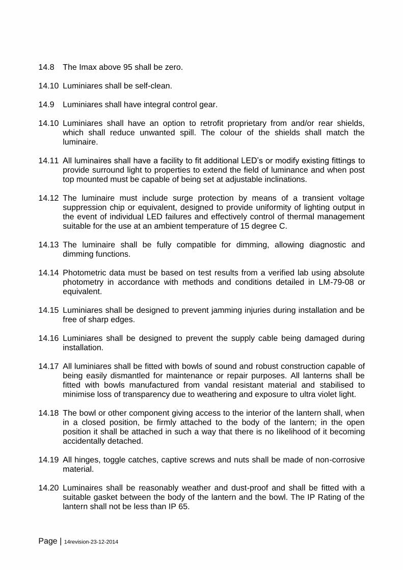
14.8 The Imax above 95 shall be zero. 14.10 Luminiares shall be self-clean. 14.9 Luminiares shall have integral control gear. 14.10 Luminiares shall have an option to retrofit proprietary from and/or rear shields,
which shall reduce unwanted spill. The colour of the shields shall match the luminaire.
14.11 All luminaires shall have a facility to fit additional LED’s or modify existing fittings to
provide surround light to properties to extend the field of luminance and when post top mounted must be capable of being set at adjustable inclinations.
14.12 The luminaire must include surge protection by means of a transient voltage
suppression chip or equivalent, designed to provide uniformity of lighting output in the event of individual LED failures and effectively control of thermal management suitable for the use at an ambient temperature of 15 degree C.
14.13 The luminaire shall be fully compatible for dimming, allowing diagnostic and
dimming functions. 14.14 Photometric data must be based on test results from a verified lab using absolute
photometry in accordance with methods and conditions detailed in LM-79-08 or equivalent.
14.15 Luminiares shall be designed to prevent jamming injuries during installation and be
free of sharp edges. 14.16 Luminiares shall be designed to prevent the supply cable being damaged during
installation. 14.17 All luminiares shall be fitted with bowls of sound and robust construction capable of
being easily dismantled for maintenance or repair purposes. All lanterns shall be fitted with bowls manufactured from vandal resistant material and stabilised to minimise loss of transparency due to weathering and exposure to ultra violet light.
14.18 The bowl or other component giving access to the interior of the lantern shall, when
in a closed position, be firmly attached to the body of the lantern; in the open position it shall be attached in such a way that there is no likelihood of it becoming accidentally detached.
14.19 All hinges, toggle catches, captive screws and nuts shall be made of non-corrosive
material. 14.20 Luminaires shall be reasonably weather and dust-proof and shall be fitted with a
suitable gasket between the body of the lantern and the bowl. The IP Rating of the lantern shall not be less than IP 65.
Page | 15revision-23-12-2014
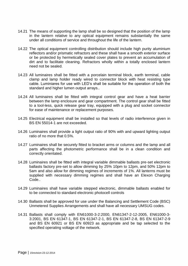
14.21 The means of supporting the lamp shall be so designed that the position of the lamp
in the lantern relative to any optical equipment remains substantially the same under all conditions of service and throughout the life of the lantern.
14.22 The optical equipment controlling distribution should include high purity aluminium
reflectors and/or prismatic refractors and these shall have a smooth exterior surface or be protected by hermetically sealed cover plates to prevent an accumulation of dirt and to facilitate cleaning. Refractors wholly within a totally enclosed lantern need not be sealed.
14.23 All luminaires shall be fitted with a porcelain terminal block, earth terminal, cable
clamp and lamp holder ready wired to connector block with heat resisting type cable. Luminiares for use with LED’s shall be suitable for the operation of both the standard and higher lumen output arrays..
14.24 All luminaires shall be fitted with integral control gear and have a heat barrier
between the lamp enclosure and gear compartment. The control gear shall be fitted to a tool-less, quick release gear tray, equipped with a plug and socket connector for ease of maintenance or replacement purposes.
14.25 Electrical equipment shall be installed so that levels of radio interference given in
BS EN 55014-1 are not exceeded. 14.26 Luminaires shall provide a light output ratio of 90% with and upward lighting output
ratio of no more that 0.5%. 14.27 Luminaires shall be securely fitted to bracket arms or columns and the lamp and all
parts affecting the photometric performance shall be in a clean condition and correctly orientated.
14.28 Luminaires shall be fitted with integral variable dimmable ballasts pre-set electronic
ballasts factory pre-set to allow dimming by 25% 10pm to 12pm, and 50% 12pm to 5am and also allow for dimming regimes of increments of 1%. All lanterns must be supplied with necessary dimming regimes and shall have an Elexon Charging Code..
14.29 Luminaires shall have variable stepped electronic, dimmable ballasts enabled for
to be connected to standard electronic photocell controls 14.30 Ballasts shall be approved for use under the Balancing and Settlement Code (BSC)
Unmetered Supplies Arrangements and shall have all necessary UMSUG codes. 14.31 Ballasts shall comply with EN61000-3-2:2000, EN61347-2-12-2005, EN61000-3-
3:2001, BS EN 61347-1, BS EN 61347-2-1, BS EN 61347-2-8, BS EN 61347-2-9 and BS EN 60921 or BS EN 60923 as appropriate and be tap selected to the specified operating voltage of the network.
Page | 16revision-23-12-2014
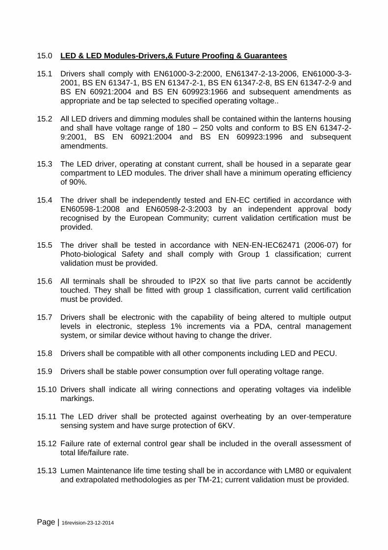
15.0 LED & LED Modules-Drivers,& Future Proofing & Guarantees 15.1 Drivers shall comply with EN61000-3-2:2000, EN61347-2-13-2006, EN61000-3-3-
2001, BS EN 61347-1, BS EN 61347-2-1, BS EN 61347-2-8, BS EN 61347-2-9 and BS EN 60921:2004 and BS EN 609923:1966 and subsequent amendments as appropriate and be tap selected to specified operating voltage..
15.2 All LED drivers and dimming modules shall be contained within the lanterns housing
and shall have voltage range of 180 – 250 volts and conform to BS EN 61347-2-9:2001, BS EN 60921:2004 and BS EN 609923:1996 and subsequent amendments.
15.3 The LED driver, operating at constant current, shall be housed in a separate gear
compartment to LED modules. The driver shall have a minimum operating efficiency of 90%.
15.4 The driver shall be independently tested and EN-EC certified in accordance with
EN60598-1:2008 and EN60598-2-3:2003 by an independent approval body recognised by the European Community; current validation certification must be provided.
15.5 The driver shall be tested in accordance with NEN-EN-IEC62471 (2006-07) for
Photo-biological Safety and shall comply with Group 1 classification; current validation must be provided.
15.6 All terminals shall be shrouded to IP2X so that live parts cannot be accidently
touched. They shall be fitted with group 1 classification, current valid certification must be provided.
15.7 Drivers shall be electronic with the capability of being altered to multiple output
levels in electronic, stepless 1% increments via a PDA, central management system, or similar device without having to change the driver.
15.8 Drivers shall be compatible with all other components including LED and PECU. 15.9 Drivers shall be stable power consumption over full operating voltage range. 15.10 Drivers shall indicate all wiring connections and operating voltages via indelible
markings. 15.11 The LED driver shall be protected against overheating by an over-temperature
sensing system and have surge protection of 6KV. 15.12 Failure rate of external control gear shall be included in the overall assessment of
total life/failure rate. 15.13 Lumen Maintenance life time testing shall be in accordance with LM80 or equivalent
and extrapolated methodologies as per TM-21; current validation must be provided.
Page | 17revision-23-12-2014
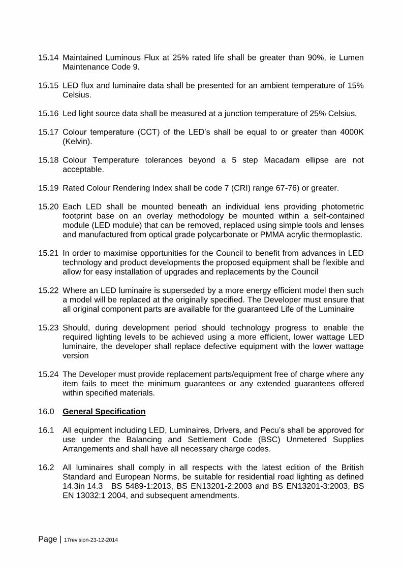
15.14 Maintained Luminous Flux at 25% rated life shall be greater than 90%, ie Lumen Maintenance Code 9.
15.15 LED flux and luminaire data shall be presented for an ambient temperature of 15%
Celsius. 15.16 Led light source data shall be measured at a junction temperature of 25% Celsius. 15.17 Colour temperature (CCT) of the LED’s shall be equal to or greater than 4000K
(Kelvin). 15.18 Colour Temperature tolerances beyond a 5 step Macadam ellipse are not
acceptable. 15.19 Rated Colour Rendering Index shall be code 7 (CRI) range 67-76) or greater. 15.20 Each LED shall be mounted beneath an individual lens providing photometric
footprint base on an overlay methodology be mounted within a self-contained module (LED module) that can be removed, replaced using simple tools and lenses and manufactured from optical grade polycarbonate or PMMA acrylic thermoplastic.
15.21 In order to maximise opportunities for the Council to benefit from advances in LED
technology and product developments the proposed equipment shall be flexible and allow for easy installation of upgrades and replacements by the Council
15.22 Where an LED luminaire is superseded by a more energy efficient model then such
a model will be replaced at the originally specified. The Developer must ensure that all original component parts are available for the guaranteed Life of the Luminaire
15.23 Should, during development period should technology progress to enable the
required lighting levels to be achieved using a more efficient, lower wattage LED luminaire, the developer shall replace defective equipment with the lower wattage version
15.24 The Developer must provide replacement parts/equipment free of charge where any
item fails to meet the minimum guarantees or any extended guarantees offered within specified materials.
16.0 General Specification 16.1 All equipment including LED, Luminaires, Drivers, and Pecu’s shall be approved for
use under the Balancing and Settlement Code (BSC) Unmetered Supplies Arrangements and shall have all necessary charge codes.
16.2 All luminaires shall comply in all respects with the latest edition of the British
Standard and European Norms, be suitable for residential road lighting as defined 14.3in 14.3 BS 5489-1:2013, BS EN13201-2:2003 and BS EN13201-3:2003, BS EN 13032:1 2004, and subsequent amendments.

Page | 18revision-23-12-2014
16.4 All Electrical Equipment shall be installed to that levels of radio interference given in BS EN 55014-1 or equivalent are not exceeded.
16.5 The system power factor shall be greater than 0.85 at full power and when dimmed. 16.6 Drivers shall be pre-set to dim by 25% between 10pm and midnight and by 50%
between midnight and 5am. 16.6 The successful bidders shall apply for the required Multi-level Switch Regime for
their equipment in accordance with Balancing and Settlement Code (BSC) procedures.
16.7 The Contractor will be responsible for making all necessary arrangements for the
collection and disposal of all luminaires replaced during the contract period in accordance with WEEE directive; any WEEE charges shall be included in the Luminaire price.
16.8 The Contractor may be required to provide technical support with the design of
luminaires to meet the requirements of the British and European Standards and subsequent amendments, following contract award. This must be provided throughout the period of the contract.
16.9 All luminaires shall be supplied fully assembled in all respects with LED, dimmable
driver and photo electric control unit at 70/35 lux. 16.10 Details the standard range of street lighting luminiares to which all persons
providing new lighting will be expected to adhere wherever possible. Any departures from these standards are to be agreed in writing with the Street Lighting Engineer prior to work commencing. Where no such prior agreement has been made the County Council reserves the right not to adopt the equipment.
16.11 Consideration shall generally be given to non-standard columns/ lanterns in
conservation areas only based upon individual assessment and future revenue implications.
16.12 Where non-standard equipment is approved the developer shall supply to Durham
County Council, at no cost, spare equipment eg lantern, bracket, column etc. The quantity to be supplied shall be 10% (rounded up) of that installed or 1no if fewer than 10 are installed.
16.13 Ballasts, Lamps, Controls etc shall be approved for use under the Balancing and
Settlement Code (BSC) Unmetered Supplies Arrangements and shall have all necessary UMSUG codes.
16.14 The luminaire life in hours shall be 80,000 hours/20year minimum 16.15 All luminaires shall be delivered pre-wired with 8 metres of 1.5 mm2 3 core arctic
flex:
Page | 19revision-23-12-2014
16.16 Standards: BS7919 Table 44, VDE281 16.17 Conductor: Class 5 flexible plain copper conductors to BS EN 60228:2005 (previously BS6360) 3 x 1.5mm2 16.18 Insulation: Arctic grade PVC (Polyvinyl Chloride) 16.19 Sheath: Arctic grade PVC (Polyvinyl Chloride) 16.20 Sheath Colour: Blue 16.21 Voltage Rating: 300/500V 16.22 Temperature Rating: -40ºC to +70ºC 17.0 Columns and Brackets 17.1 Columns shall be manufactured from galvanised tubular/ sheet steel, or aluminium
and shall conform to the following: 17.2 The column and bracket manufacturer shall be registered with and accredited under
the Quality Assurance Scheme ISO9002 for the manufacture, supply and verification of lighting columns. A copy of the accreditation document shall be supplied to the Engineer on request.
17.2 All columns and brackets shall be manufactured, supplied and installed in
accordance with the requirements of BS5649 or revision of such. Columns shall be manufactured in accordance with the requirements of BSEN40 and amendments by BD 26/04. The design of all columns shall include for the mounting of a sign plate 5kg x 0.3m2 x 1.8 shape co-efficient mounted 2.5 metres above ground and with 300mm eccentricity.
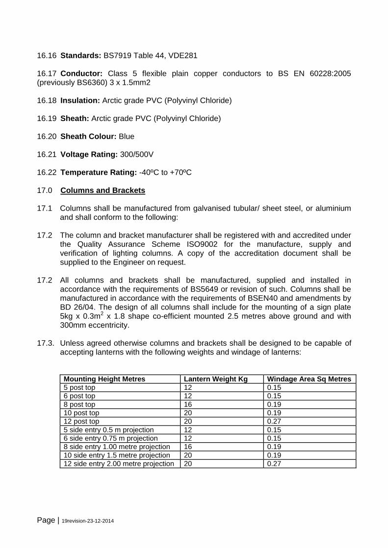
17.3. Unless agreed otherwise columns and brackets shall be designed to be capable of
accepting lanterns with the following weights and windage of lanterns:
Mounting Height Metres Lantern Weight Kg Windage Area Sq Metres
5 post top 12 0.15
6 post top 12 0.15
8 post top 16 0.19
10 post top 20 0.19
12 post top 20 0.27
5 side entry 0.5 m projection 12 0.15
6 side entry 0.75 m projection 12 0.15
8 side entry 1.00 metre projection 16 0.19
10 side entry 1.5 metre projection 20 0.19
12 side entry 2.00 metre projection 20 0.27
Page | 20revision-23-12-2014
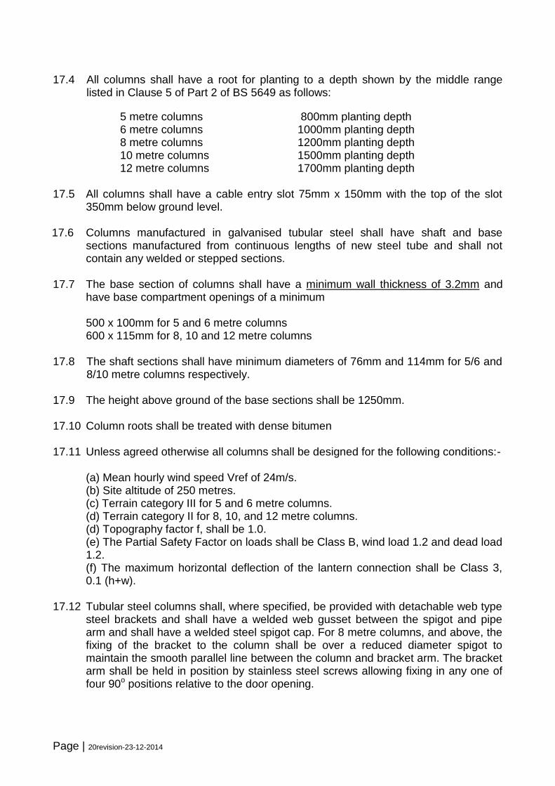
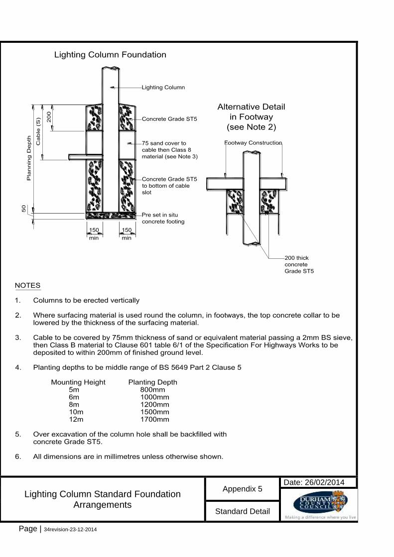
17.4 All columns shall have a root for planting to a depth shown by the middle range listed in Clause 5 of Part 2 of BS 5649 as follows:
5 metre columns 800mm planting depth 6 metre columns 1000mm planting depth 8 metre columns 1200mm planting depth 10 metre columns 1500mm planting depth 12 metre columns 1700mm planting depth 17.5 All columns shall have a cable entry slot 75mm x 150mm with the top of the slot
350mm below ground level.
17.6 Columns manufactured in galvanised tubular steel shall have shaft and base sections manufactured from continuous lengths of new steel tube and shall not contain any welded or stepped sections.
17.7 The base section of columns shall have a minimum wall thickness of 3.2mm and have base compartment openings of a minimum
500 x 100mm for 5 and 6 metre columns 600 x 115mm for 8, 10 and 12 metre columns 17.8 The shaft sections shall have minimum diameters of 76mm and 114mm for 5/6 and
8/10 metre columns respectively. 17.9 The height above ground of the base sections shall be 1250mm.
17.10 Column roots shall be treated with dense bitumen
17.11 Unless agreed otherwise all columns shall be designed for the following conditions:- (a) Mean hourly wind speed Vref of 24m/s. (b) Site altitude of 250 metres. (c) Terrain category III for 5 and 6 metre columns. (d) Terrain category II for 8, 10, and 12 metre columns. (d) Topography factor f, shall be 1.0. (e) The Partial Safety Factor on loads shall be Class B, wind load 1.2 and dead load
1.2. (f) The maximum horizontal deflection of the lantern connection shall be Class 3,
0.1 (h+w). 17.12 Tubular steel columns shall, where specified, be provided with detachable web type
steel brackets and shall have a welded web gusset between the spigot and pipe arm and shall have a welded steel spigot cap. For 8 metre columns, and above, the fixing of the bracket to the column shall be over a reduced diameter spigot to maintain the smooth parallel line between the column and bracket arm. The bracket arm shall be held in position by stainless steel screws allowing fixing in any one of four 90o positions relative to the door opening.
Page | 21revision-23-12-2014
17 13 A means of preventing undesired rotational movement of the bracket, once fixed in position, to the column shaft shall be incorporated in the column design.
17.14 Bracket arms shall, , provide an incline of lantern of 5° , or 0° in Environmental Zone
E1 or specified otherwise, when fitted to spigots of: (a) 42mm OD x 110mm long for 5 and 6 metre columns (b) 42mm OD x 127mm long for 8,10 and 12 metre columns.
17.15 The method of joining the base section and the shaft shall be by a swage joint with an internal centralising washer. All welding procedures shall be in accordance with the requirements of BS EN288 and all welders approved to the requirements of BS EN287 with welding carried out in accordance with BS 5135.
17.16 The same pattern of door lock shall be used throughout all columns. Keys shall be
supplied for 10% of all columns supplied. The door fixing bolt shall have a tapered end to facilitate self centering when closing.
17.17 An internal full length base board, equivalent to the door size, substantially non-
hygroscopic, shall be fitted in each compartment for mounting control gear. Base board fixing studs or bolts shall not protrude beyond the front face of the base board. The base board shall be firmly bolted in position. On delivery, the column door shall come assembled on the column.
17.18 All columns shall be fitted with M8 x 30mm brass earth studs, threaded the
whole length, with two plain washers and two nuts within the base compartment and that are easily accessible. Column doors shall be provided with an internal lug to enable earthling of the column door with an M8 brass earth stud.
17.19 There shall be no sharp edges within columns or bracket arms to damage electrical
cables during installation or service. An anti-chafe ring shall be fitted where cable routes change direction from horizontal to vertical within the bracket.
17.20 Raise and Lower columns: 17.21 shall be installed at such locations where vehicular access is severely limited, for
example, remote footpaths or where the presence of a maintenance vehicle may impede the free flow of traffic. Refuge Island beacon posts may fall within this latter category.
17.22 shall generally comply with the Clauses above and shall be erected in accordance
with manufacturer’s instructions and recommendations. The oiling point, provided for the lubrication of the hinged cam, shall be attended to during Routine Maintenance visits.
17.23 shall be supplied with: 17.24 No door - access to electrical equipment only in lowered position, or,
Columns shall be either mid or base hinged
Page | 22revision-23-12-2014
17.25 All new roads above 50mph shall be designed to include passively safe street lighting columns and sign posts in accordance with the British/CEN standards EN12767 and reference shall be made to the County Surveyors, Transport for London research document SL04/07, the Institution of Lighting Professionals Technical Report TR30, and the passive revolution shall be considered and DCC Street Lighting Policy.
18.00 Corrosion Protection for Steel Columns and Brackets 18.1 All columns and bracket arms shall be galvanised unpainted. Additional protection
shall be used for columns and bracket arms within a conservation area or as agreed with the Director of Neighbourhood Services. Additional protection, as per the treatment below, shall be applied before leaving the factory.
i) Hot dipped galvanised in accordance with BS EN 150 1461 1999. ii)The galvanised surface shall then be degreased and left with a smooth
finish to prepare for painting. 18.2 The paint system shall comprise:
1st Coat - On the internal root section, to 250mm above ground level and on the overall external surfaces, one coat of Mordant Solution, T wash.
2nd Coat - On the internal root section, to 250mm above ground level, one coat of modified vinyl micaceous iron oxide with high solids to give a high build coating colour grey to provide a minimum dry film thickness of 60 microns.
3rd Coat - On the external surface overall, one coat of two pack high build epoxy zinc phosphate primer, light grey to provide a minimum dry film thickness of 75 microns.
4th Coat - On the external root section to 250mm above ground level, one coat of modified vinyl micaceous iron oxide with high solids to give a high build coating, coloured grey to provide a minimum dry film thickness of 75 microns.
5th Coat - On the external surface overall, one coat of modified vinyl with high solids to give a sheen finish to the dried film colour grey from BS 4800 shade 18B25 to provide a minimum dry film thickness of 60 microns.
A line on the circumference of the base section shall denote ground level.
The minimum dry film thickness shall be:
Root - 60μm (internal) 210μm (external to 250mm)
External - 135μm (from 250mm)
19 Light Sources 19.1 The type of light source, its colour and colour appearance can have a significant
effect on the night scene. The attributes of the various light sources that shall be considered for public lighting are:-
Page | 23revision-23-12-2014
LED.-Light Emitting Diode
Low maintenance implications
Low energy usage
Extensive Lamp Life
White light source
Luminaires still under development . 19.2 Where. British Standards allow the lowering of lighting classes for light sources with
good colour rendering, in compliance with local strategies, or where dictated by environmental/ safety factors, LED’s shall be used in all circumstances.
19.3 LED’s must comply with the latest revision of all ruling legislation at the time of
supply including:
EC Declaration of Conformity (CE Mark)
Full compliance RoHS Directive 2002/95/EC and all related UK legislation
Full compliance WEEE Directive 2002/96/EC and all related UK legislation
EuP Directive 2005/32/EC and all related UK legislation 19.4 All lamps supplied shall carry markings in conformity with the above legislation and
any other mandatory markings ruling at the time of supply.
a) shock and vibration.
19.5 Light Emitting Diode (LED) lamps Typical LED’s.
a) EC Declaration of conformity certificate shall be provided.
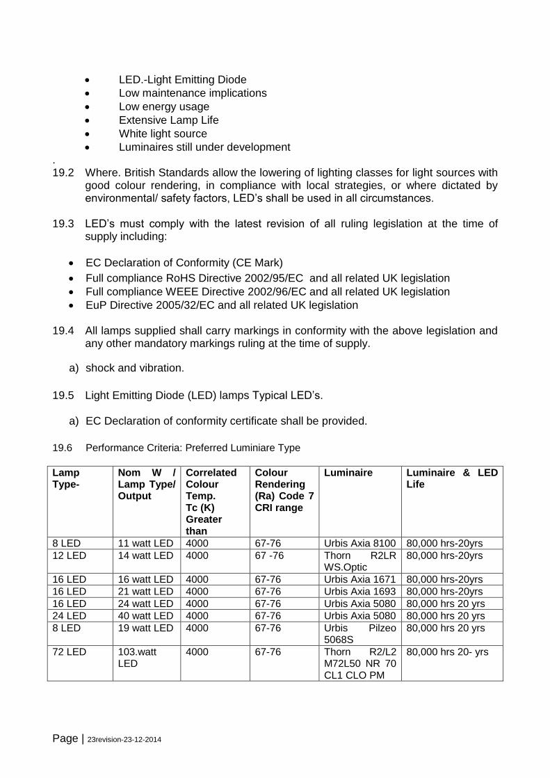
19.6 Performance Criteria: Preferred Luminiare Type
Lamp Type-
Nom W / Lamp Type/ Output
Correlated Colour Temp. Tc (K) Greater than
Colour Rendering (Ra) Code 7 CRI range
Luminaire Luminaire & LED Life
8 LED 11 watt LED 4000 67-76 Urbis Axia 8100 80,000 hrs-20yrs
12 LED 14 watt LED 4000 67 -76 Thorn R2LR WS.Optic
80,000 hrs-20yrs
16 LED 16 watt LED 4000 67-76 Urbis Axia 1671 80,000 hrs-20yrs
16 LED 21 watt LED 4000 67-76 Urbis Axia 1693 80,000 hrs-20yrs
16 LED 24 watt LED 4000 67-76 Urbis Axia 5080 80,000 hrs 20 yrs
24 LED 40 watt LED 4000 67-76 Urbis Axia 5080 80,000 hrs 20 yrs
8 LED 19 watt LED 4000 67-76 Urbis Pilzeo 5068S
80,000 hrs 20 yrs
72 LED 103.watt LED
4000 67-76 Thorn R2/L2 M72L50 NR 70 CL1 CLO PM
80,000 hrs 20- yrs
Page | 24revision-23-12-2014
20.0 Clear Cut Outs and Isolators 20.1 All cut-outs shall be clear and incorporate a double pole isolation switch complying
with BS5419 having a rating of 32 amps and of adequate short circuit withstand for the position in the circuit in which it is installed. The isolation switch shall be capable of being positively and visibly locked off by means of a padlock or locking bar and it shall not be possible to remove the outgoing fuse(s) unless the isolation switch is in the off position.
20.2 The cut-outs shall be of the all insulated type with drip proof enclosure affording a
minimum degree of protection to IP22 and have a high mechanical and dielectric strength. The terminals shall be capable of accepting conductors with crimped lug connectors.
20.3 The incoming phase terminals shall be shrouded when all connections have been
made, the shroud shall be capable of removal for inspection or disconnection of cable ends, but shall not be capable of accidental detachment or be of a push fit type. Movement of cables shall be prevented by the use of bushes or inserts. Fuse carriers shall utilise HRC fuse links to BS 88.
20.4 The units shall be provided with separate terminals for phase and neutral
conductors manufactured from solid brass and electro-tinned and are entirely suitable for connecting the requisite cables.
20.5 Where connection is made into any cut-out for supplying a sub-circuit the cut-out
shall incorporate a second fuse link to protect the sub-circuit. 20.6 Electricity Service Connections cut-outs shall be manufactured by Tofco or and be
double pole or similar approved by DCC. 20.7 The cut-outs shall be securely fitted to the baseboard with non-corrodible screw
fixings. 21 Fuses 21.1 No rewirable fuses shall be used. All fuses to be HRC to BS88 Part 2 operating on
240 volts 50Hz supply. Fuse ratings shall be 6 amps for lamps up to and including 100watt and 10 amps for lamps greater than 100 watts.
22 Cables 22.1 Underground cables shall be laid in duct except where they leave the duct to enter
the cable slot of the apparatus, and consist of stranded copper conductors, XLPE insulated, PVC extruded bedding, a concentric layer of steel wire armour, overall PVC sheathing suitable for operation in an earthed system and of rated voltage 600/1000 volts at 50HZ, all in accordance with BS 6346 for metric cable, have BASEC approval under the product certification scheme and produced by a manufacturer who has been awarded a Certificate of Assessed Quality Management, to BS 5750, by BASEC.
Page | 25revision-23-12-2014
22.2 All cores shall be of equal cross sectional area of 6sq mm minimum and be of such
a size that the requirements of the current IEE Wiring Regulation, BS 7671, are met and allow for a disconnection time not exceeding 5 seconds.
22.3 Internal wiring between the terminal block in the lantern and the components in the
base of the column shall be PVC insulated and sheathed cable of 300/500 volt grade, have a copper conductor size of not less than 2.5 sq mm.
22.4 Where approved, cable to a two part photo electric cell detector unit shall be 1.5 sq mm two core flat with white sheath.
22.5 All cores shall be correctly colour coded and cables for continuous earth bonding shall be green/yellow PVC insulated single core copper cable of minimum cross section 6 sq mm 600 volt grade conforming to BS 6004.
22.6 All underground cables (except Regional Electricity Company cables) shall be identified as to their origin and destination by permanent markers located over the sheath at the cable ends. An example is shown in Appendix 5.
23 Cable Ducts
23.1. Cable ducts across roadways shall have internal diameters of 100 mm and average
wall thickness of 5.0 mm. Cable ducts in footpaths and verges shall have internal diameters of 50 mm and average wall thickness of 3.5 mm.
23.2 Ducts shall be manufactured from low, medium or high density polyethylene and coloured orange with white, 9 mm high lettering “STREET LIGHTING” at intervals of not more than 1m along its length.
23.3 Ducts for street lighting cables under carriageways shall be laid with 750 mm minimum cover and laid on 100 mm bed of Acceptable Material Class 8 (Specification of Highway Works) and covered with Acceptable Material Class 8 but containing no material greater than 20 mm within 100 mm of the duct.
23.0 Cable Laying
23.1 Joints in underground cables are not permitted and continuous lengths of cable shall be laid and looped in and out of the terminations.
23.2 Cables shall not be laid in a frozen state or when the ambient temperature is below
0c.
23.3 The internal radius of a cable bend shall be such as not to cause damage to the cable.
23.4 For cables not accommodated in 50 mm duct, the trench shall be excavated to 525 mm minimum depth and the cable laid on and surrounded by a 75 mm thickness of sand or equivalent material. The trench to be back filled with acceptable material to
Page | 26revision-23-12-2014
within 150 mm of finished level before laying the cable marker tape and completing the backfill and finished surface.
24.00 Erection of Columns and Brackets
24.1 The columns shall be erected in the locations shown on the approved drawings. Columns shall be set on a 450 x 450 x 50 mm paving slab at the level necessary to obtain the required planting depth. The column shall be correctly aligned in the vertical position with the door opening facing away from oncoming traffic.
24.2 The columns shall be placed in a hole allowing a minimum of 150 mm clearance all-round the base of the column for the full excavation depth. The column foundation shall be formed as shown in Appendix 6 or as otherwise directed by the Director of Neighbourhood Services.
24.3 Concrete used in the backfill shall be grade ST5 as specified in the Specification for Highway Works.
24.4 Bracket arms shall be fixed to the columns at the site of installation. The method of securing the bracket arm must be positive such that the arm cannot rotate. The arm and lantern shall be at right angles to the highway to be illuminated.
25 Internal Wiring and Distribution Cables
26.1 Columns not directly supplied from Electricity Company supplies shall be supplied on a sub-circuit from the serviced column by means of the public lighting underground cable and looped from column to column. All looped connections shall be made in the bottom terminals of the fused isolator cut-out. The armouring of the underground cables shall be secured onto the gland plate of the cut-out or have a nonferrous sleeve fitted below the armouring and earthing clamps fitted to make a positive grip on the armour wires. The earthing clamps and gland plate shall be bonded to the main column earthing terminal with 10 sq mm single core PVC cable.
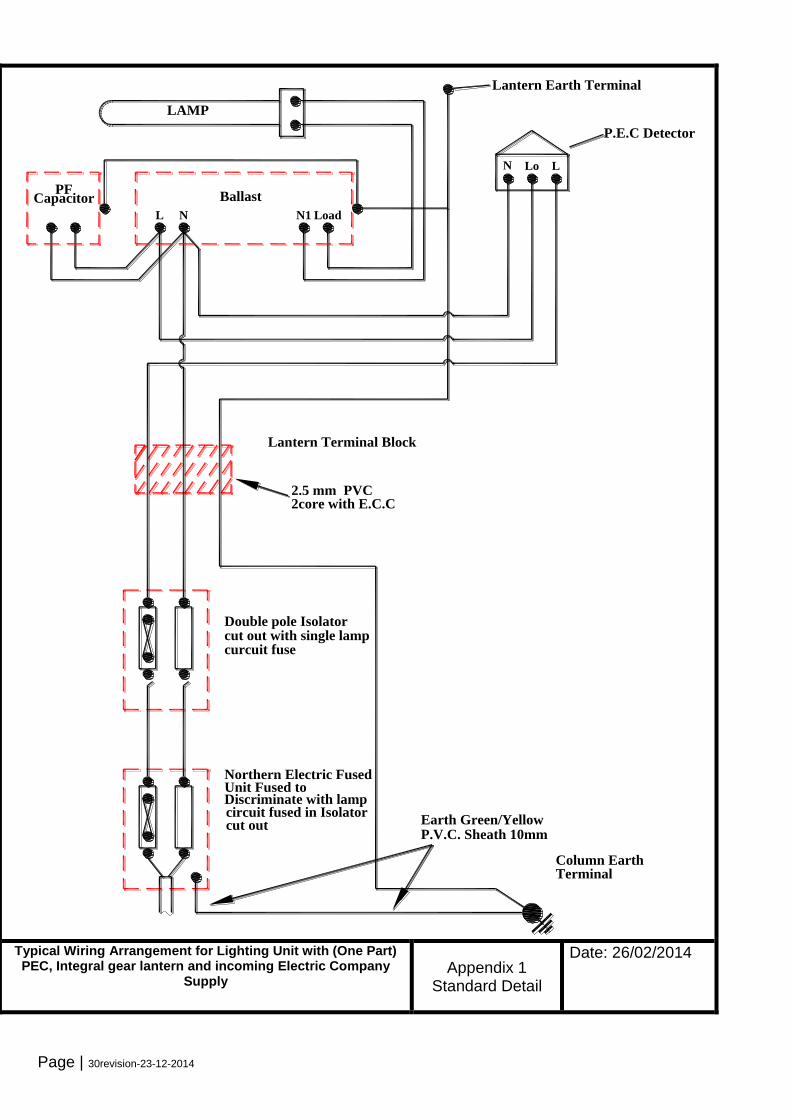
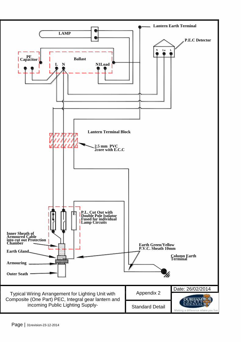
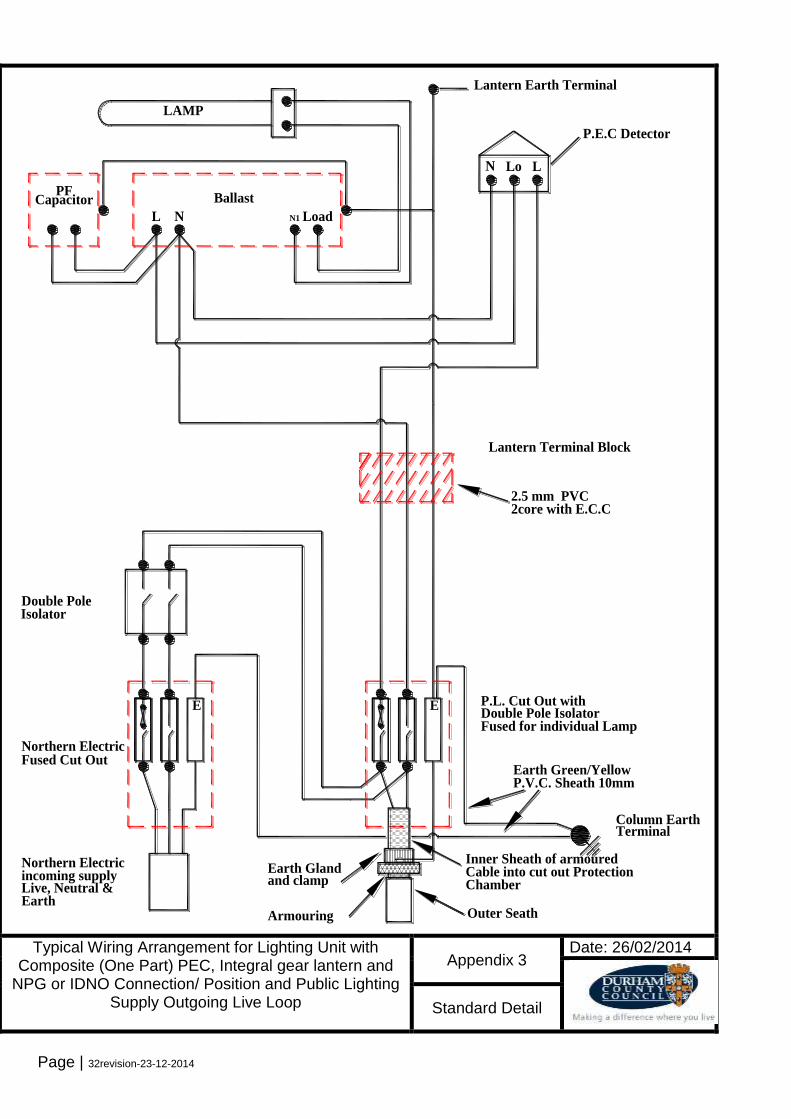
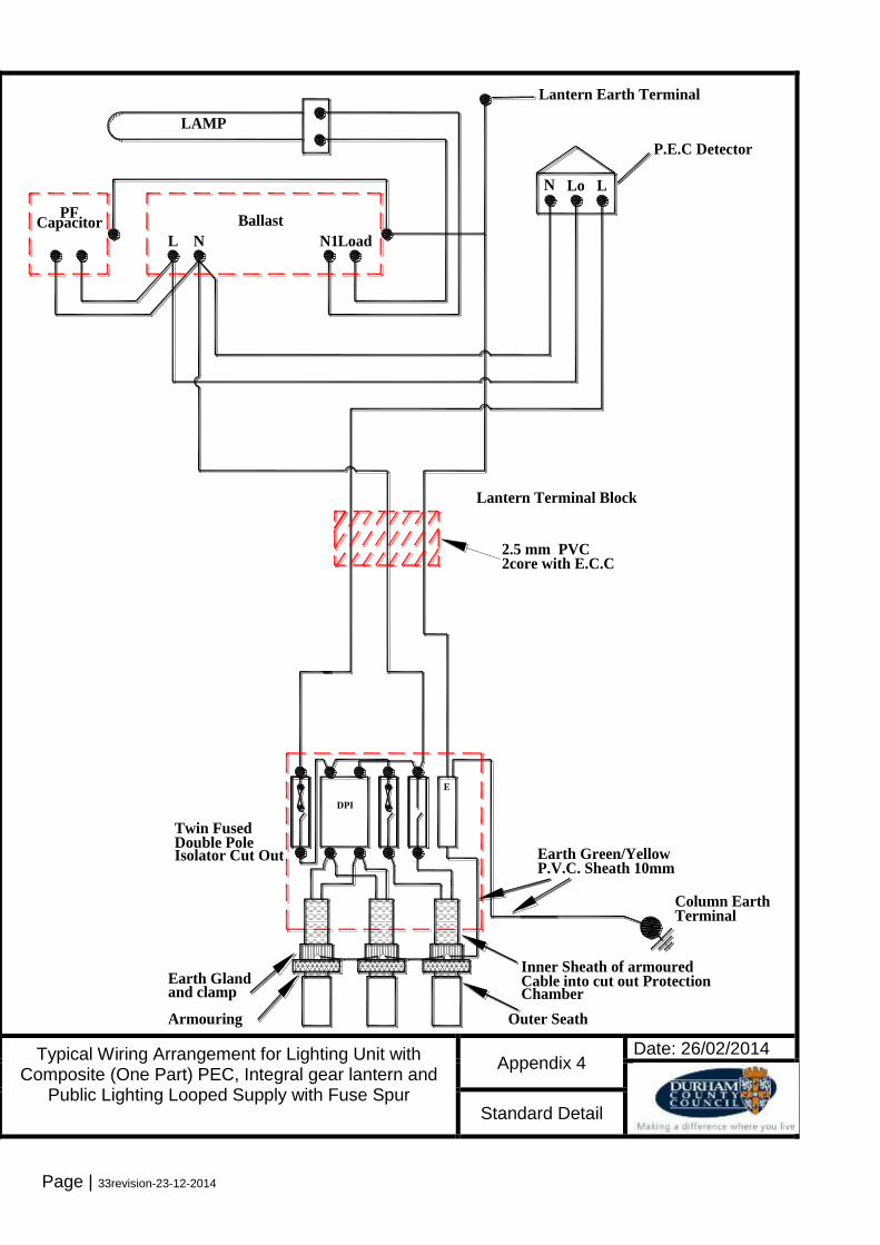
25.2 Typical wiring diagrams are shown in Appendices 1 to 4.
26 Illuminated Road Traffic Signs 26.1 Where it is necessary, all illuminated road traffic signs shall be provided by the
developer and shall be as prescribed in the Traffic Signs Regulations and General Directions 1994, the Traffic Signs (Speed Limits) Regulations and any amendments. They shall be provided where directed by the Director of Environment and Technical Services to whom details of any proposals must be submitted for approval.
26.2 Posts for Illuminated Traffic Signs
Page | 27revision-23-12-2014
26.3 A post with base housing shall be provided for each overhead sign lighting unit and cut out and service connections made in the base housing. All metal posts shall be tubular steel section and supplied in accordance with BS 873 and BSEN 10210.
26.4 The corrosion protection for sign posts shall be as that specified for street lighting columns in Clause 11 of this specification.
26.5 Sign Plates
All plates shall be of a size, colour and type prescribed by the Secretary of State as indicated in the Traffic Sign Regulations. All parts of the sign assemblies shall be designed and manufactured to withstand a minimum wind pressure of 1.5 KN/square metres. Plates shall be manufactured from aluminium or plastic coated steel which shall have a ten year guarantee applicable to the reflective material and substrate. All signs shall have class one reflective material (encapsulated lens) fully reflectorised.
26.6 Sign Lanterns
Sign lanterns shall comply in all respects with the requirement of Section 4, BS873 and BS1788 where applicable. The lantern for overhead illumination of plates up to 750mm diameter shall house one LED The unit shall be manufactured from LM6-M cast aluminium and incorporate a fully detachable gear try and alloy frame supported polycarbonate lens that pivots or hinges downwards leaving the sign light canopy intact and providing weatherproof protection to the electrics and lighting unit during maintenance operations. The sign lantern and bracket shall be as manufactured by Simmonsigns type LUA or similar approved.
26.7 Illuminated Signs on Pedestrian Refuge Islands
Unless otherwise agreed the signs used at such locations shall be of the demountable type with the installation incorporating cable chambers and post sheaths as depicted on standard detail drawing, Appendix 7.
26.8 Shall be SELV 24 low voltage-in the lighting column or waterproof IP 67 pit or box. 27.00 Electricity Supply Services
27.1 The developer shall liaise with the Regional Electricity Company (Northern Power
Grid, or Independent Distribution Operator) with regard to provision of electricity supply services to the lighting installation and this information shall be provided together with the Mpan number and Lighting level on all drawings.
27.2 Northern Power Grid or Independent Distributor shall be advised that where a significant number of services are required, the developer should contact the
Page | 28revision-23-12-2014
appropriate NPG or IDNO office eight weeks prior to the supply being required, and provide the following:-
(a) A schedule of lamps requiring a new supply or transfer of supply.
(b) Two plans of the approved lighting scheme.
(c) An indication of when the work will be required.
NPG or IDNO will return one of the plans, a written quotation and a schedule of the columns that are to receive a new or transferred supply. The developer will be required to confirm acceptance of terms and to give at least four weeks’ notice of a “site ready date” when work on site can commence. Northern Electric will require payment in advance of work commencing and also require the developer to install all service and cross road ducts to their specification.
27.3 Where public lighting underground supplies are to be drawn from the Electricity
Company fuse unit, the developer shall provide and fix a public lighting cut-out at that service position. UNDER NO CIRCUMSTANCES SHALL CONNECTIONS BE MADE TO THE LIVE SIDE OF THE ELECTRICITY COMPANY CUT-OUT.
28.0 Earthing
28.1 The whole of the installation shall be earthed in accordance with the requirements of the current BS 7671, IEE Wiring Regulations, and with the recommendations contained in BS 7430, Earthing. Earthing shall be carried out in PVC insulated copper cable green/yellow in colour. All metallic parts of the ancillary equipment, column, lantern and gear shall be bonded together to form a continuous earth path to the earth stud of the column.
29.0. Painting
29.1 After erection, any areas of damage to the paint protection system shall be made
good by abrading the edges of the damaged areas and coating the damaged areas with M.I.O. modified vinyl, applied by spray, to give a sheen finish coloured grey 18B25.
29.2 No further site painting of new columns shall be required unless a finish in a colour
other than grey is required. Any further finish paint shall be applied to the overall column and bracket in one continuous flow free coat. All painting shall be carried out in accordance with the paint manufacturer’s instructions and no painting shall be carried out during extremes of temperature or when the surface is damp or wet.
30.0. Electrical Testing of Equipment and Commissioning
30.1 Prior to being energised, all equipment wiring and cabling of every completed
installation shall be tested in accordance with Part 7 of BS7671.
Page | 29revision-23-12-2014
30.2 Testing shall be carried out in compliance with the Electricity at Work Regulations
1989 and such that no danger to persons or property or damage to equipment can occur even if the tested circuit is defective.
30.3 The columns and underground cables should be tested in the following sequence.
1. Visual Inspection – to verify that the electrical equipment has been correctly installed in accordance with the design with correctly rated protection devices and bonding and that no visible damage exists.
2. Continuity – every protective conductor, including bonding, shall be tested to
verify that it is electrically sound. 3. Insulation Resistance – the insulation resistance should be measured
between all the conductors and the conductors to earth with a test voltage of 500 volts. The insulation resistance should not be less than 0.5 megohm.
4. Polarity – a polarity test should be made and a check to verify that protective
devices are connected correctly and fuses in the phase conductor only. 5. Earth Fault Loop Impedance – measurements should be taken at the point of
supply and, where underground cables have been installed, at the most distant point of each circuit. The values should accord with those shown in BS 7671 to ensure the circuit protective device will function within five seconds.
6. Earth Electrode Resistance – tested in accordance with BS 7430 and BS
7671. 7. Operation of Residual Current Device – verify by a test simulating an
appropriate fault condition independent of any test facility incorporated in the device. The device shall be tested at 50% and 100% of its rated trip current.
8. Voltage Drop – measured at the most remote point from the supply under full
load conditions.
30.4 All results shall be recorded and submitted to the Director of Neighbourhood Services prior to a Part 2 adoption inspection. The results, for each unit, shall be recorded on the forms shown in appendix 10 or such similar in accordance with BS 7671 subject to approval.
Page | 30revision-23-12-2014
cut out
INCOMING ELECTRC COMPANY SUPPLY
WITH (ONE PART) PEC, INTEGRAL GEAR LANTERN
TYPICAL WIRING ARRANGEMENT FOR LIGHTING UNIT
APPENDIX 1
P.E.C Detector
TerminalColumn Earth
P.V.C. Sheath 10mmEarth Green/Yellow
circuit fused in IsolatorDiscriminate with lamp Unit Fused to Northern Electric Fused
curcuit fusecut out with single lampDouble pole Isolator
LN Lo
Lantern Earth Terminal
LAMP
CapacitorPF
Ballast
LoadN1NL
2.5 mm PVC
Lantern Terminal Block
2core with E.C.C
Typical Wiring Arrangement for Lighting Unit with (One Part) PEC, Integral gear lantern and incoming Electric Company
Supply
Appendix 1 Standard Detail
Date: 26/02/2014
Page | 31revision-23-12-2014
Lamp Circuits
Outer Seath
Armouring
Earth Gland
into cut out Protection Armoured Cable Inner Sheath of
Fused for individualDouble Pole IsolatorP.L. Cut Out withE
WITH COMPOSITE (ONE PART) P.E.C.
TYPICAL WIRING ARRANGEMENT FOR LIGHTING UNIT
APPENDIX 2
P.E.C Detector
TerminalColumn Earth
P.V.C. Sheath 10mmEarth Green/Yellow
LN Lo
Lantern Earth Terminal
LAMP
CapacitorPF
Ballast
LoadN1NL
2core with E.C.C2.5 mm PVC
Lantern Terminal Block
Chamber
Typical Wiring Arrangement for Lighting Unit with Composite (One Part) PEC, Integral gear lantern and
incoming Public Lighting Supply-
Appendix 2 Date: 26/02/2014
Standard Detail
Page | 32revision-23-12-2014
PUBLIC LIGHTING OUTGOING LIVE LOOP
NORTHERN ELECTRIC SERVICE POSITION AND
WITH COMPOSITE (ONE PART) P.E.C.
TYPICAL WIRING ARRANGEMENT FOR LIGHTING UNIT
EarthLive, Neutral &incoming supplyNorthern Electric
IsolatorDouble Pole
Fused Cut OutNorthern Electric
and clamp
E
Outer SeathArmouring
Earth Gland Cable into cut out ProtectionInner Sheath of armoured
Fused for individual LampDouble Pole IsolatorP.L. Cut Out withE
APPENDIX 3
P.E.C Detector
TerminalColumn Earth
P.V.C. Sheath 10mmEarth Green/Yellow
LN Lo
Lantern Earth Terminal
LAMP
CapacitorPF
Ballast
LoadN1NL
2core with E.C.C2.5 mm PVC
Lantern Terminal Block
Chamber
Typical Wiring Arrangement for Lighting Unit with Composite (One Part) PEC, Integral gear lantern and
NPG or IDNO Connection/ Position and Public Lighting Supply Outgoing Live Loop
Appendix 3 Date: 26/02/2014
Standard Detail
Page | 33revision-23-12-2014
Isolator Cut OutDouble Pole Twin Fused
DPI
LOOPS CABLE WITH FUSED SPUR
WITH COMPOSITE (ONE PART) P.E.C. AND PUBLIC LIGHTING
TYPICAL WIRING ARRANGEMENT FOR LIGHTING UNIT
and clamp
Outer SeathArmouring
Earth Gland Cable into cut out ProtectionInner Sheath of armoured
E
APPENDIX 4
P.E.C Detector
TerminalColumn Earth
P.V.C. Sheath 10mmEarth Green/Yellow
LN Lo
Lantern Earth Terminal
LAMP
CapacitorPF
Ballast
LoadN1NL
2.5 mm PVC
Lantern Terminal Block
2core with E.C.C
Chamber
Typical Wiring Arrangement for Lighting Unit with Composite (One Part) PEC, Integral gear lantern and
Public Lighting Looped Supply with Fuse Spur
Appendix 4 Date: 26/02/2014
Standard Detail
Page | 34revision-23-12-2014
Lighting Column Standard Foundation Arrangements
Appendix 5 Date: 26/02/2014
Standard Detail
Page | 35revision-23-12-2014
1250mm
90
0m
m
Min
imu
m W
idth
18
00m
m
39
0m
m(m
in)
IP67 uderground
waterproof GRP
junction box
Inspection chamber lid 275 x 285mm,
with stainless steel fixings. (Must be
installed flush with the surface)
Pedestrian island to consist of 125 x 255mm
half-batter kerbing with 125mm upstand.
Kerb upstand to be painted white.
0.75mm² 3 core TRS flexible cable
& 6m ² Green/Yellow earth bond
100mm Cross C/way duct
100mm cross carriageway duct to be installed to
Drawing No. HMS/05/28 to terminate in extension box.
NOTES
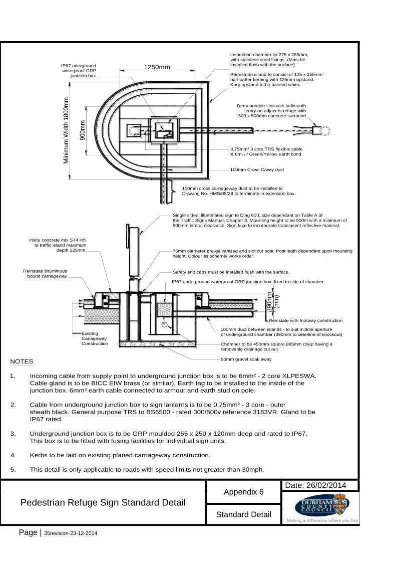
1. Incoming cable from supply point to underground junction box is to be 6mm² - 2 core XLPESWA.
Cable gland is to be BICC EIW brass (or similar). Earth tag to be installed to the inside of the
junction box. 6mm² earth cable connected to armour and earth stud on pole.
2. Cable from underground junction box to sign lanterns is to be 0.75mm² - 3 core - outer
sheath black. General purpose TRS to BS6500 - rated 300/500v reference 3183VR. Gland to be
IP67 rated.
3. Underground junction box is to be GRP moulded 255 x 250 x 120mm deep and rated to IP67.
This box is to be fitted with fusing facilities for individual sign units.
4. Kerbs to be laid on existing planed carriageway construction.
5. This detail is only applicable to roads with speed limits not greater than 30mph.
Existing
Cariageway
Construction
Single sided, illuminated sign to Diag 610, size dependant on Table A of
the Traffic Signs Manual, Chapter 3. Mounting height to be 900m with a minimum of
500mm lateral clearance. Sign face to incorporate translucent reflective material.
76mm diameter pre-galvanised and slot cut post. Post legth dependant upon mounting
height. Colour as scheme/ works order.
Safety end caps must be installed flush with the surface.
IP67 underground waterproof GRP junction box, fixed to side of chamber.
Reinstate bituminous
bound carriageway
Insitu concrete mix ST4 infil
to traffic island maximum
depth 125mm.
Reinstate with footway construction.
100mm duct between islands - to suit middle aperture
of underground chamber (390mm to ceterline of knockout)
Chamber to be 450mm square 885mm deep having a
removable drainage cut out.
50mm gravel soak away
Demountable Unit with bellmouth
entry on adjacent refuge with
500 x 500mm concrete surround
Pedestrian Refuge Sign Standard Detail
Appendix 6 Date: 26/02/2014
Standard Detail

Page | 36revision-23-12-2014
Appendix 7: Standard Range of Street Lighting Lanterns
Appendix 7: ELECTRICAL TEST SHEET (page 1 of 2) SITE NAME: ___________________________________ DEVELOPER: ___________________________________ DISTRICT: _____________________ PARISH: ________________________ UNIT No: ___________ TOWN: ________________________________ STREET: __________________________________________ LOCATION: ______________________________________________________________________________ TYPE (eg Ltg Col, Illuminated Sign etc): ________________________________________________________ POST HEIGHT: ___________ MATERIAL: ______________________________________________ POSITION: ON A BRIDGE/ CENTRAL RESERVE/ FRONT OF PATH/ REAR OF PATH/ IN GARDEN/ ON ROUNDABOUT/ ON SIDE OF ROAD/ ON SLIP ROAD/ ON SPLITTER ISLAND/ IN VERGE MANUFACTURER: ____________________________ COATING: ______________________________ FLANGED: YES/ NO RAISE & LOWER: YES/ NO CONDITION: GOOD/ AVERAGE/ POOR BRACKET TYPE: ____________________________________ PROJECTION: __________ No OF BKTS: _______ BRACKET CONDITION: GOOD/ AVERAGE/ POOR
LANTERN 1 LANTERN 2 LANTERN 3
LANTERN MANUF
LANTERN MODEL
MATRIX/ OPTIC POS
PROFILE
BALLAST MANUF
BALLAST REF
CAPACITOR MANUF
CAPACITOR REF
PEC MANUF
PEC REF
LAMP TYPE
LAMP WATTAGE
No OF LAMPS
VISUAL INSPECTION SATISFACTORY YES/ NO
COMMENTS INCLUDING REPAIRS MADE
SYSTEM & EARTHING TYPE: ______________________ SUPPLY VOLTAGE: _________ TRIP LAMP/ FEEDER PILLAR No.: ____________ P.S.C.C.: _________________ kA
INTERNAL WIRING CONTINUITY INSULATION RESISTANCE
L - N L - E N – E
CABLE 1 LANTERN
CABLE 2 PEC

Page | 37revision-23-12-2014
CABLE 3
Appendix 10: ELECTRICAL TEST SHEET (page 2 of 2)
CUT OUT 1 TYPE CUT OUT 2 TYPE
E.L.I. AT CUT OUT E.L.I. AT CUT OUT
LAMP FUSE TYPE RATING LAMP FUSE TYPE RATING
OUTGOING FUSE TYPE RATING OUTGOING FUSE TYPE RATING
CABLE A (incoming) B (outgoing) C (outgoing) D (outgoing) E (outgoing)
FROM
TO
LENGTH (m)
CABLE REF
CABLE OWNER
CABLE TYPE, MATERIAL, CSA, No of CORES
CONTINUITY (OHMS)
INS RES (MOHMS) POLARITY
E L N L - N L - E N - E E L N
A
B
C
D
E
R.C.D. INSTALLED: YES/ NO LOAD RATING (A) ________ TRIP RATING (Ma): __________ MANUFACTURER: _____________________________ MODEL REF: ___________________________ OPERATION: ½ = _________________ ms 1 = _____________________ ms EARTH ELECTRODE RESISTANCE (IF INSTALLED): _____________ OHMS
COMMENTS
I CERTIFY THAT THE ABOVE INSTALLATION HAS BEEN INSPECTED IN ACCORDANCE WITH THE CURRENT IEE REGULATIONS SIGNED: _________________________________________ DATE: _____________________ PRINT NAME: ________________________________________

Page 38
Appendix 8-DCC Scheme Approval Checklist
Submitted/Information Provided
Yes No Approved Rejected
Name of Developer
Name of consultant/architect
Contact details of developer
Contact details of consultant
Name of builder if different from above
Contact details of builder if different from above
Name of street sighting electrical Contractor
Contact details of electrical contractor
AutoCAD (dwg) & PDF formats for street lighting layout complete with unique drawing number, including modifications through the development.
Lighting Calculations (Reality)
Proposed luminaire and reference including manufacturer
Details of electrical equipment used and manufacturer
Proposed low voltage distribution network
Electrical test Results.
Electrical supplies to individual units
NPG/IDNO/ICP details
Scheme detailed inventory