strategic environmental research and development … · dr. polina snugovsky, celestica; dr....
TRANSCRIPT
©2015 BAE Systems, All rights reserved
Strategic Environmental Research and Development Program (SERDP) Nanoparticle enhanced conformal coating project: Coating
modeling for tin whisker mitigation
S. McKeown, S. Meschter; BAE SystemsP. Snugovsky, J. Kennedy, Z. Bagheri, J. Keeping;
CelesticaJ. Cho; Binghamton University
D. Edwards; Henkel LLCK. Elsken; Covestro LLC
1
Originally published in the Proceedings of SMTA International,Rosemont, IL, September 27-October 1, 2015.
DoD/EPA/DOE SERDP WP-2213: Novel Whisker Mitigating Composite Conformal Coat Assessment
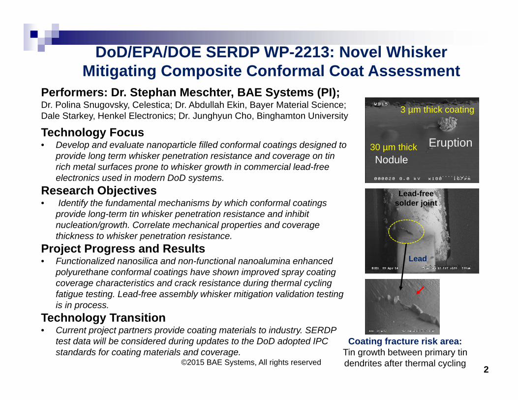
Performers: Dr. Stephan Meschter, BAE Systems (PI); Dr. Polina Snugovsky, Celestica; Dr. Abdullah Ekin, Bayer Material Science; Dale Starkey, Henkel Electronics; Dr. Junghyun Cho, Binghamton University
Technology Focus• Develop and evaluate nanoparticle filled conformal coatings designed to
provide long term whisker penetration resistance and coverage on tin rich metal surfaces prone to whisker growth in commercial lead-free electronics used in modern DoD systems.
Research Objectives• Identify the fundamental mechanisms by which conformal coatings
provide long-term tin whisker penetration resistance and inhibit nucleation/growth. Correlate mechanical properties and coverage thickness to whisker penetration resistance.
Project Progress and Results• Functionalized nanosilica and non-functional nanoalumina enhanced
polyurethane conformal coatings have shown improved spray coating coverage characteristics and crack resistance during thermal cycling fatigue testing. Lead-free assembly whisker mitigation validation testing is in process.
Technology Transition• Current project partners provide coating materials to industry. SERDP
test data will be considered during updates to the DoD adopted IPC standards for coating materials and coverage.
EruptionNodule
3 µm thick coating
30 µm thick
Lead
Lead-free solder joint
Coating fracture risk area: Tin growth between primary tin dendrites after thermal cycling 2
©2015 BAE Systems, All rights reserved
©2015 BAE Systems, All rights reserved
Outline/Agenda IntroductionWhiskers Coating mitigation
Analysis A simple experiment ConclusionsQ & A
3
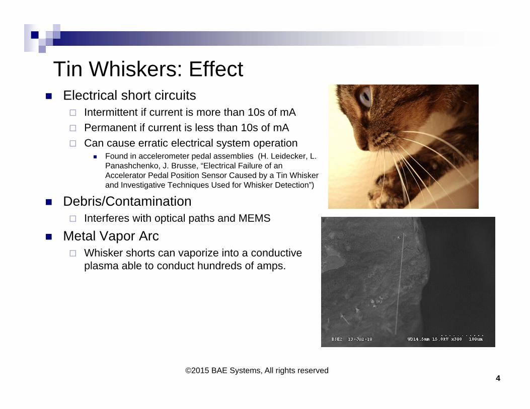
Tin Whiskers: Effect Electrical short circuits
Intermittent if current is more than 10s of mA Permanent if current is less than 10s of mA Can cause erratic electrical system operation
Found in accelerometer pedal assemblies (H. Leidecker, L. Panashchenko, J. Brusse, “Electrical Failure of an Accelerator Pedal Position Sensor Caused by a Tin Whisker and Investigative Techniques Used for Whisker Detection”)
Debris/Contamination Interferes with optical paths and MEMS
Metal Vapor Arc Whisker shorts can vaporize into a conductive
plasma able to conduct hundreds of amps.
4©2015 BAE Systems, All rights reserved
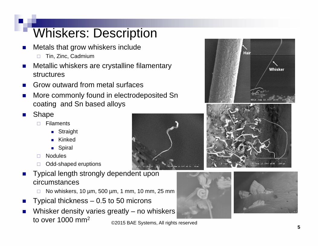
Whiskers: Description Metals that grow whiskers include
Tin, Zinc, Cadmium
Metallic whiskers are crystalline filamentary structures
Grow outward from metal surfaces More commonly found in electrodeposited Sn
coating and Sn based alloys Shape
Filaments Straight Kinked Spiral
Nodules Odd-shaped eruptions
Typical length strongly dependent upon circumstances No whiskers, 10 µm, 500 µm, 1 mm, 10 mm, 25 mm
Typical thickness – 0.5 to 50 microns Whisker density varies greatly – no whiskers
to over 1000 mm2
5©2015 BAE Systems, All rights reserved
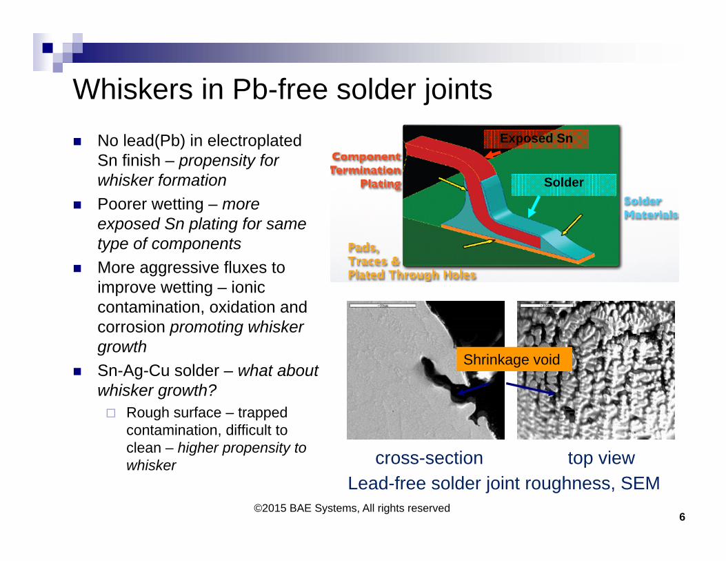
Whiskers in Pb-free solder joints No lead(Pb) in electroplated
Sn finish – propensity for whisker formation
Poorer wetting – more exposed Sn plating for same type of components
More aggressive fluxes to improve wetting – ionic contamination, oxidation and corrosion promoting whisker growth
Sn-Ag-Cu solder – what about whisker growth? Rough surface – trapped
contamination, difficult to clean – higher propensity to whisker
6
top viewLead-free solder joint roughness, SEM
cross-section
Shrinkage void
Exposed Sn
Solder
©2015 BAE Systems, All rights reserved

Whiskers in Pb-free solder joints
64 pin thin quad flat pack, 0.4 mm pitch Cleaned part before assembly and cleaned after soldering
4,000 hours at 85ºC/85%RH©2015 BAE Systems, All rights reserved
7
If assembly was coated, this region would be
well covered
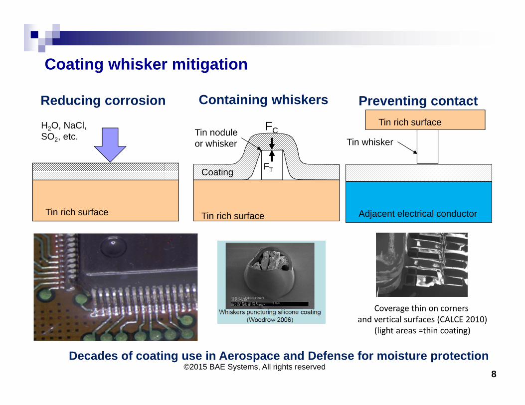
Coating whisker mitigation
8
Tin noduleor whisker
FTCoating
FC
Tin rich surface
Tin whisker
Adjacent electrical conductor
Tin rich surface
Containing whiskers Preventing contactReducing corrosion
H2O, NaCl, SO2, etc.
Tin rich surface
Decades of coating use in Aerospace and Defense for moisture protection
Coverage thin on corners and vertical surfaces (CALCE 2010)
(light areas =thin coating)
©2015 BAE Systems, All rights reserved
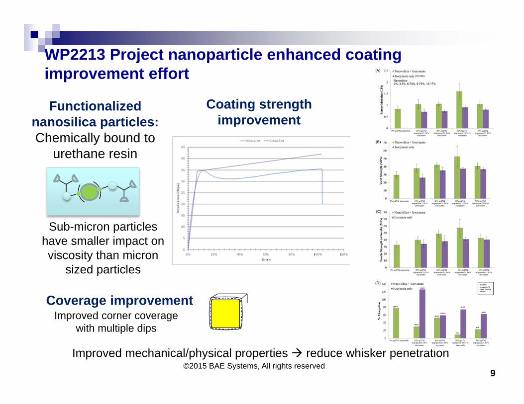
WP2213 Project nanoparticle enhanced coating improvement effort
9
Improved mechanical/physical properties reduce whisker penetration
Improved corner coverage with multiple dips
Coverage improvement
Coating strength improvement
Functionalized nanosilica particles:Chemically bound to
urethane resin
Sub-micron particles have smaller impact on viscosity than micron
sized particles
©2015 BAE Systems, All rights reserved
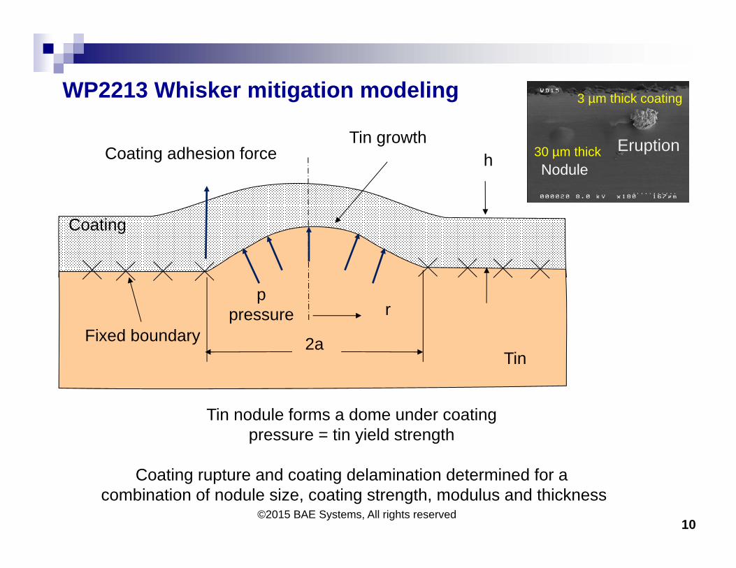
WP2213 Whisker mitigation modeling
10©2015 BAE Systems, All rights reserved
Coating
h
Tin2a
Tin growth
r
Coating adhesion force
Fixed boundary
ppressure
Tin nodule forms a dome under coatingpressure = tin yield strength
Coating rupture and coating delamination determined for acombination of nodule size, coating strength, modulus and thickness
EruptionNodule
3 µm thick coating
30 µm thick
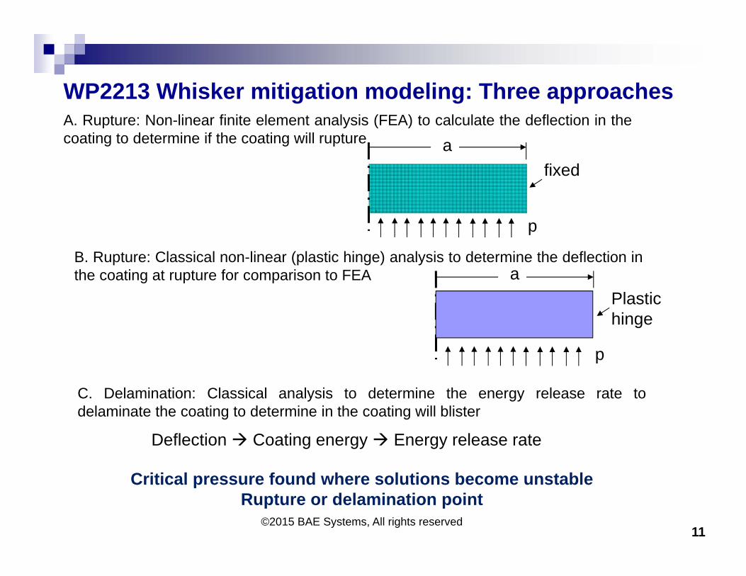
WP2213 Whisker mitigation modeling: Three approaches
11©2015 BAE Systems, All rights reserved
Critical pressure found where solutions become unstable Rupture or delamination point
A. Rupture: Non-linear finite element analysis (FEA) to calculate the deflection in thecoating to determine if the coating will rupture
B. Rupture: Classical non-linear (plastic hinge) analysis to determine the deflection inthe coating at rupture for comparison to FEA
C. Delamination: Classical analysis to determine the energy release rate todelaminate the coating to determine in the coating will blister
p
afixed
p
aPlastichinge
Deflection Coating energy Energy release rate
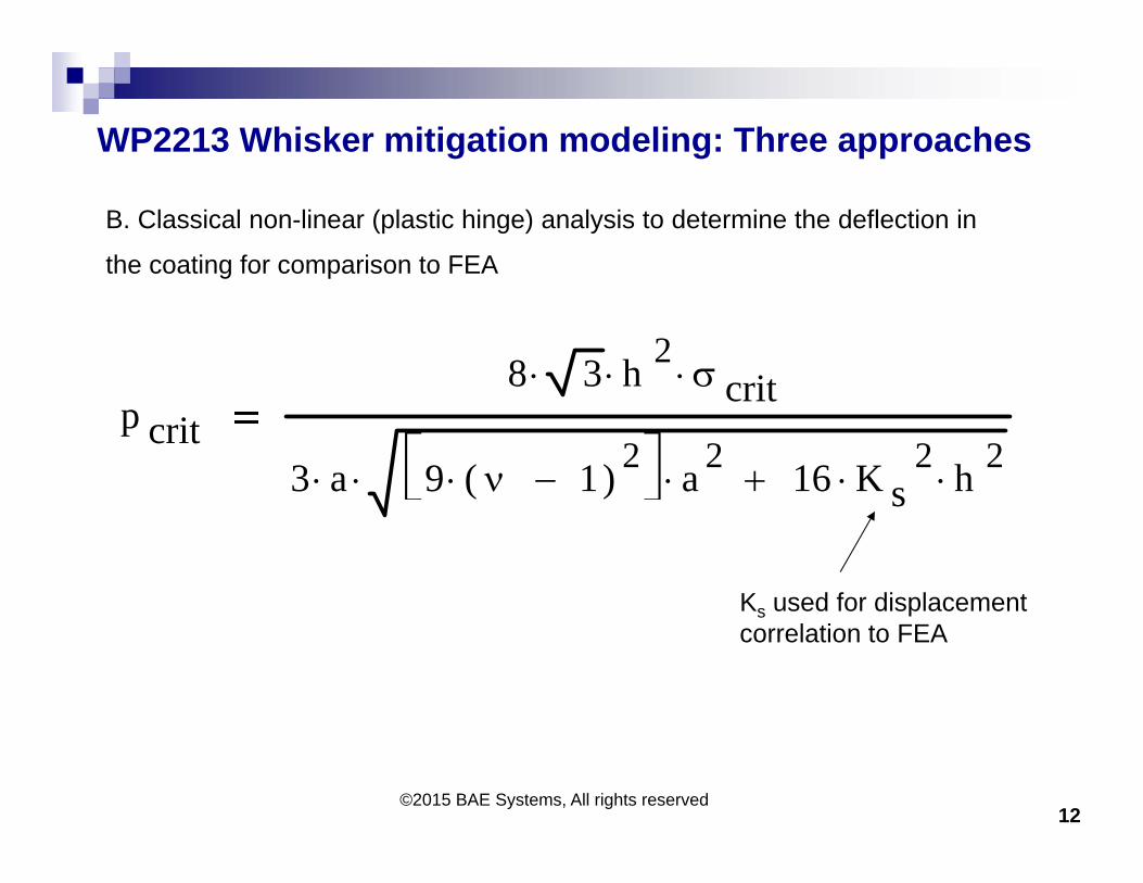
WP2213 Whisker mitigation modeling: Three approaches
12©2015 BAE Systems, All rights reserved
p crit8 3 h 2
crit
3 a 9 1( ) 2 a 2
16 K s2
h 2
B. Classical non-linear (plastic hinge) analysis to determine the deflection in
the coating for comparison to FEA
Ks used for displacementcorrelation to FEA
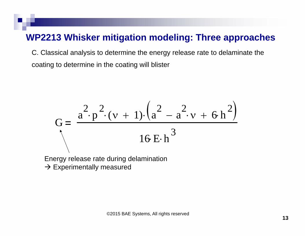
WP2213 Whisker mitigation modeling: Three approaches
13©2015 BAE Systems, All rights reserved
C. Classical analysis to determine the energy release rate to delaminate the
coating to determine in the coating will blister
Ga2 p 2 1( ) a2 a2
6 h 2
16 E h 3
Energy release rate during delamination Experimentally measured
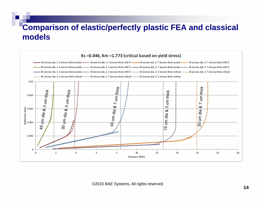
Comparison of elastic/perfectly plastic FEA and classical models
14©2015 BAE Systems, All rights reserved
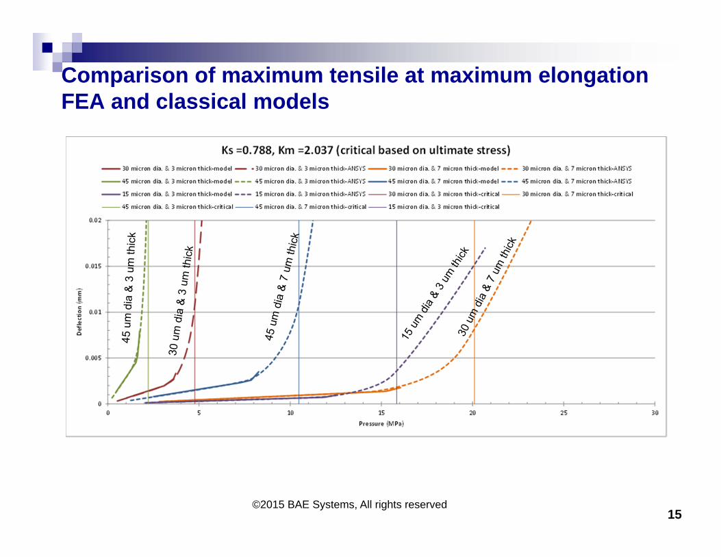
Comparison of maximum tensile at maximum elongation FEA and classical models
15©2015 BAE Systems, All rights reserved
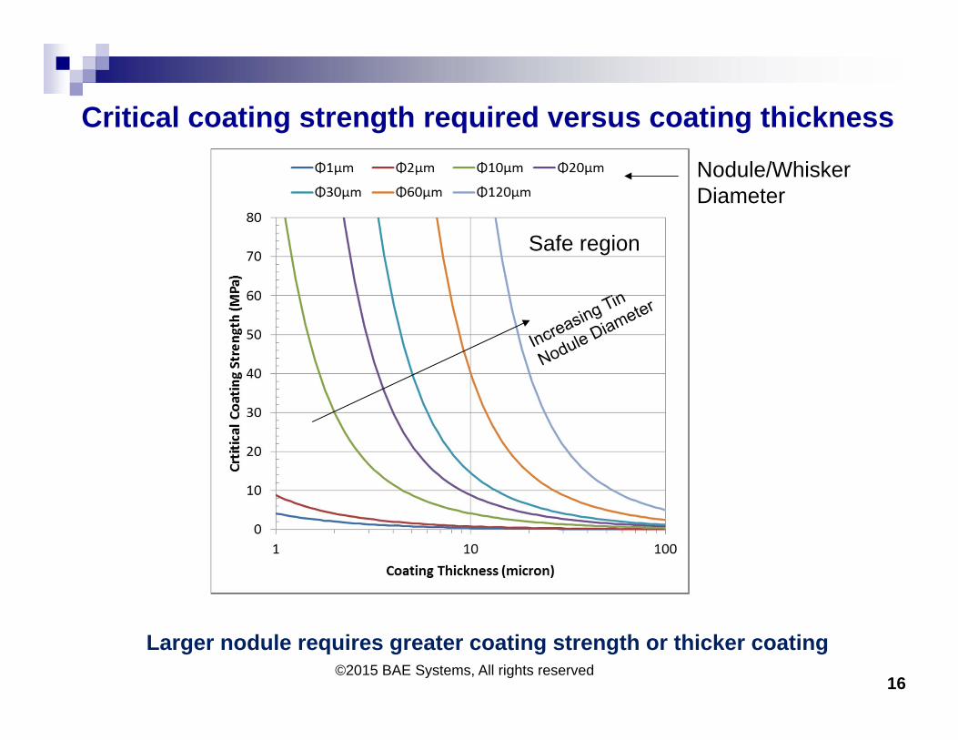
Critical coating strength required versus coating thickness
16©2015 BAE Systems, All rights reserved
Larger nodule requires greater coating strength or thicker coating
Safe region
Nodule/Whisker Diameter
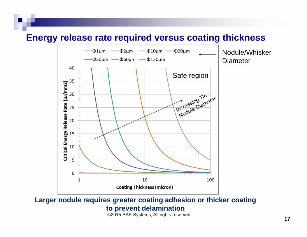
Energy release rate required versus coating thickness
17©2015 BAE Systems, All rights reserved
Larger nodule requires greater coating adhesion or thicker coating to prevent delamination
Safe region
Nodule/Whisker Diameter
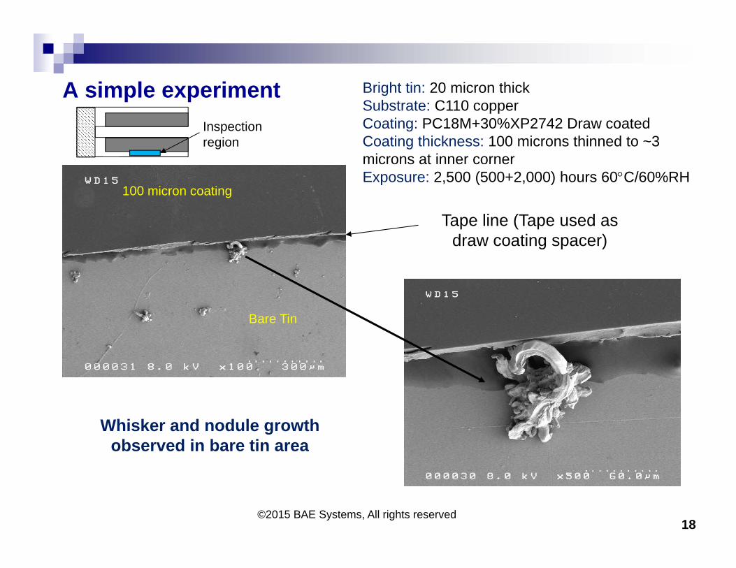
A simple experiment
18©2015 BAE Systems, All rights reserved
Inspection region
100 micron coating
Bare Tin
Whisker and nodule growth observed in bare tin area
Bright tin: 20 micron thick Substrate: C110 copperCoating: PC18M+30%XP2742 Draw coatedCoating thickness: 100 microns thinned to ~3 microns at inner cornerExposure: 2,500 (500+2,000) hours 60C/60%RH
Tape line (Tape used as draw coating spacer)
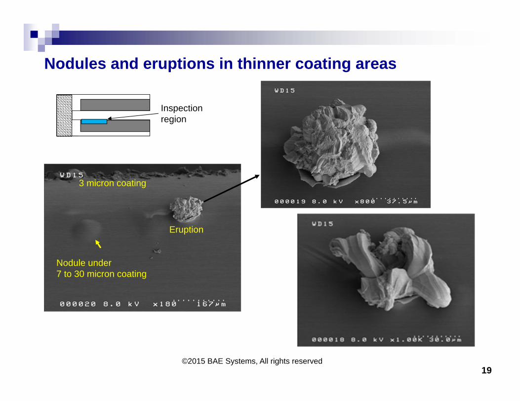
Nodules and eruptions in thinner coating areas
19©2015 BAE Systems, All rights reserved
Inspection region
Nodule under 7 to 30 micron coating
3 micron coating
Eruption
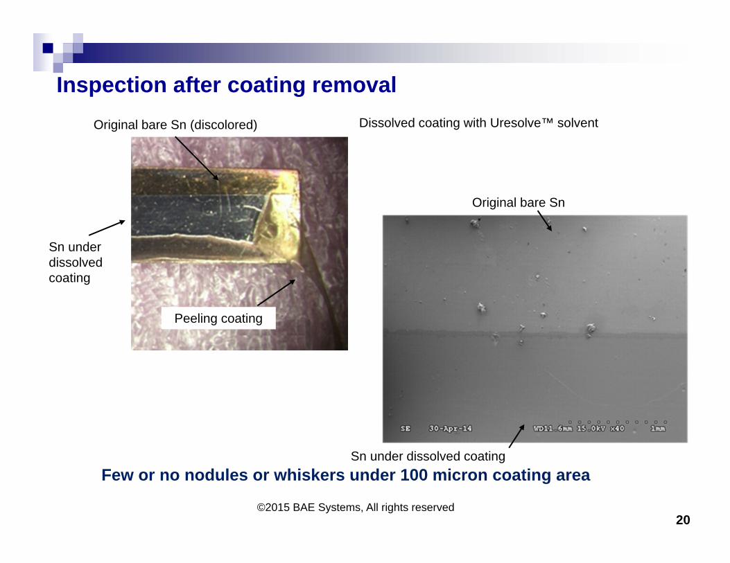
Inspection after coating removal
20©2015 BAE Systems, All rights reserved
Original bare Sn (discolored)
Sn under dissolved coating
Peeling coating
Original bare Sn
Sn under dissolved coatingFew or no nodules or whiskers under 100 micron coating area
Dissolved coating with Uresolve™ solvent
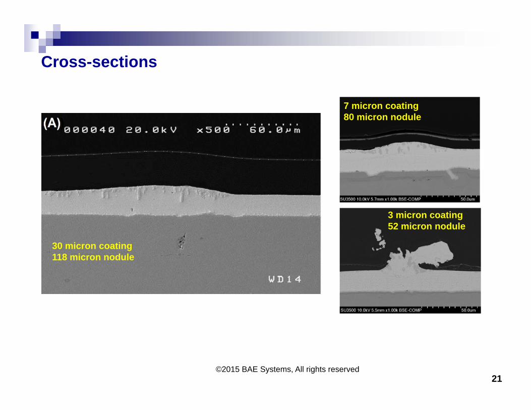
Cross-sections
21©2015 BAE Systems, All rights reserved
30 micron coating118 micron nodule
7 micron coating80 micron nodule
3 micron coating52 micron nodule
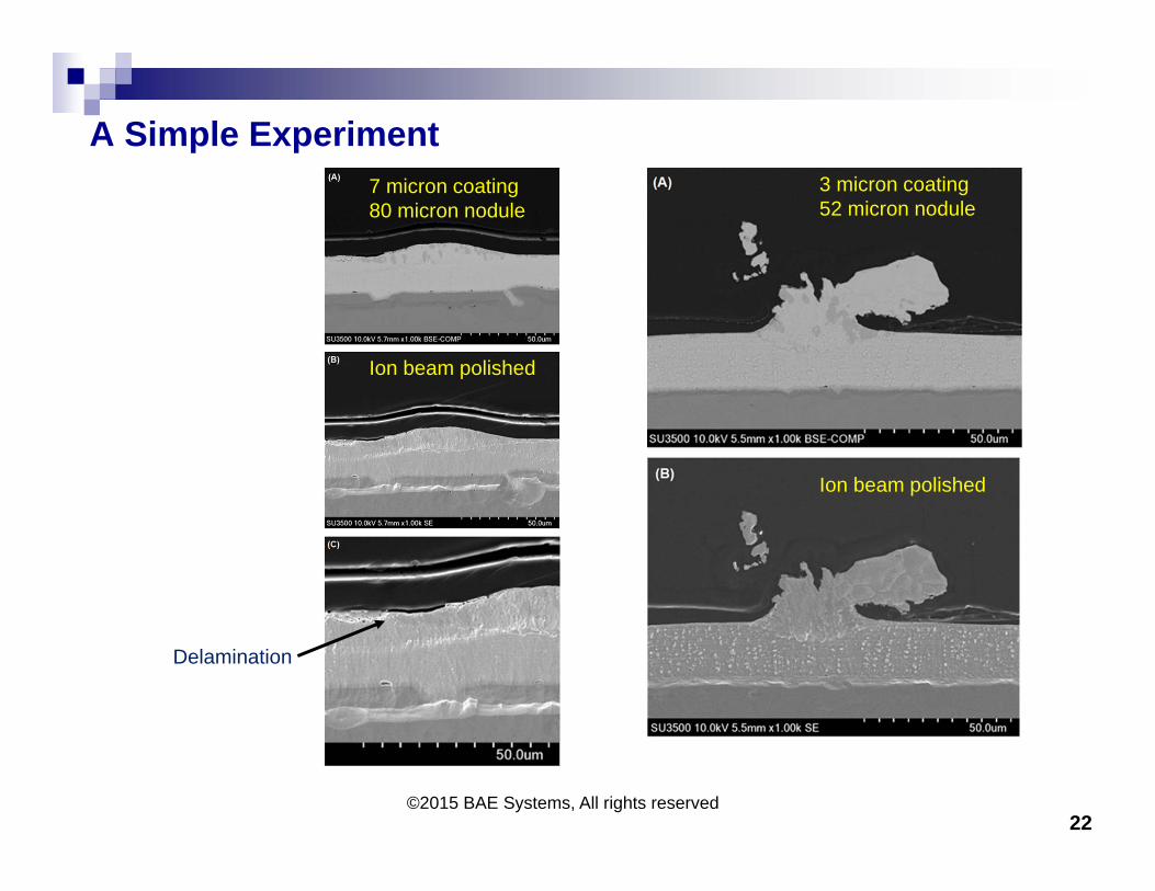
A Simple Experiment
22©2015 BAE Systems, All rights reserved
7 micron coating80 micron nodule
3 micron coating52 micron nodule
Ion beam polished
Ion beam polished
Delamination
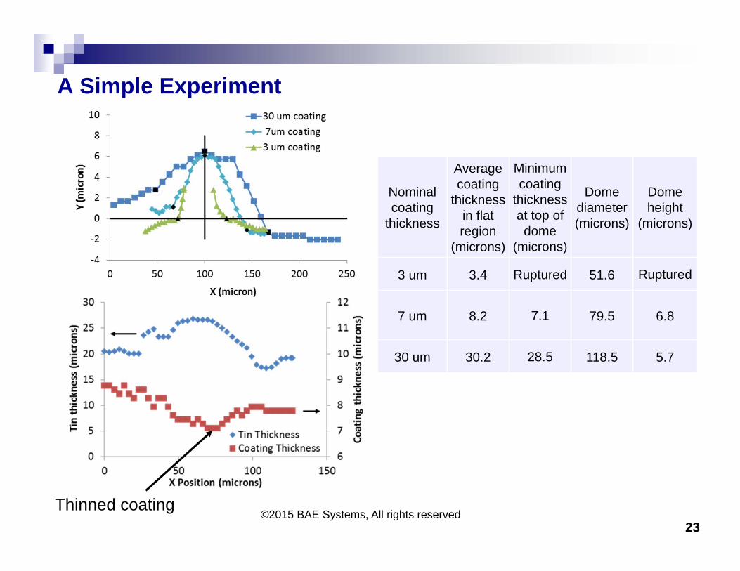
A Simple Experiment
23©2015 BAE Systems, All rights reserved
Thinned coating
Nominalcoating
thickness
Average coating
thickness in flat region
(microns)
Minimum coating
thickness at top of dome
(microns)
Dome diameter (microns)
Dome height
(microns)
3 um 3.4 Ruptured 51.6 Ruptured
7 um 8.2 7.1 79.5 6.8
30 um 30.2 28.5 118.5 5.7

Critical coating strength required versus coating thickness
24©2015 BAE Systems, All rights reserved
Larger nodule requires greater coating strength or thicker coating
No nodules under 100 micron coating
30 micron coating118 micron nodule
3 micron coating52 micron nodule
7 micron coating80 micron nodule
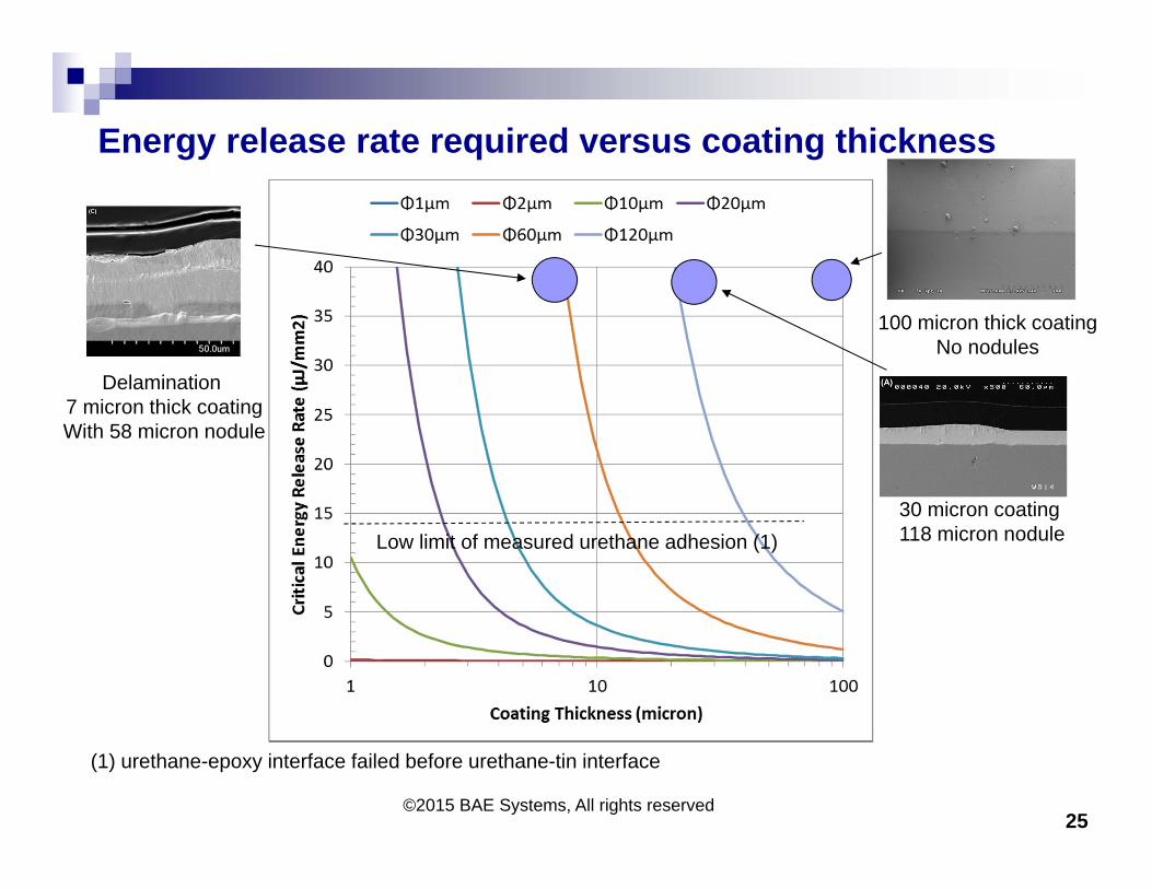
Energy release rate required versus coating thickness
25©2015 BAE Systems, All rights reserved
Delamination 7 micron thick coatingWith 58 micron nodule
Low limit of measured urethane adhesion (1)
(1) urethane-epoxy interface failed before urethane-tin interface
100 micron thick coatingNo nodules
30 micron coating118 micron nodule
Conclusions The FEA modeling predicted rupture of a three micron thick coating
which was consistent with the rigid coating experimental observations.
Energy release rate results also indicate that delamination of a 100 micron coating thickness is unlikely for typical whisker diameters.
There is a combination of coating thickness, strength and adhesion that can provide whisker mitigation
In contrast to smaller diameter whiskers, larger diameter tin nodule formations have greater potential to rupture the coating
The whisker growth surface stress relaxation phenomena causing formation of the tin filament structure is altered in the presence of a coating having high adhesion, high strength, and sufficient thickness
Note: Although rigid coatings can inhibit tin nodule/whisker formation they need to be evaluated for potential impacts to solder joint thermal cycling fatigue reliability
©2015 BAE Systems, All rights reserved 26
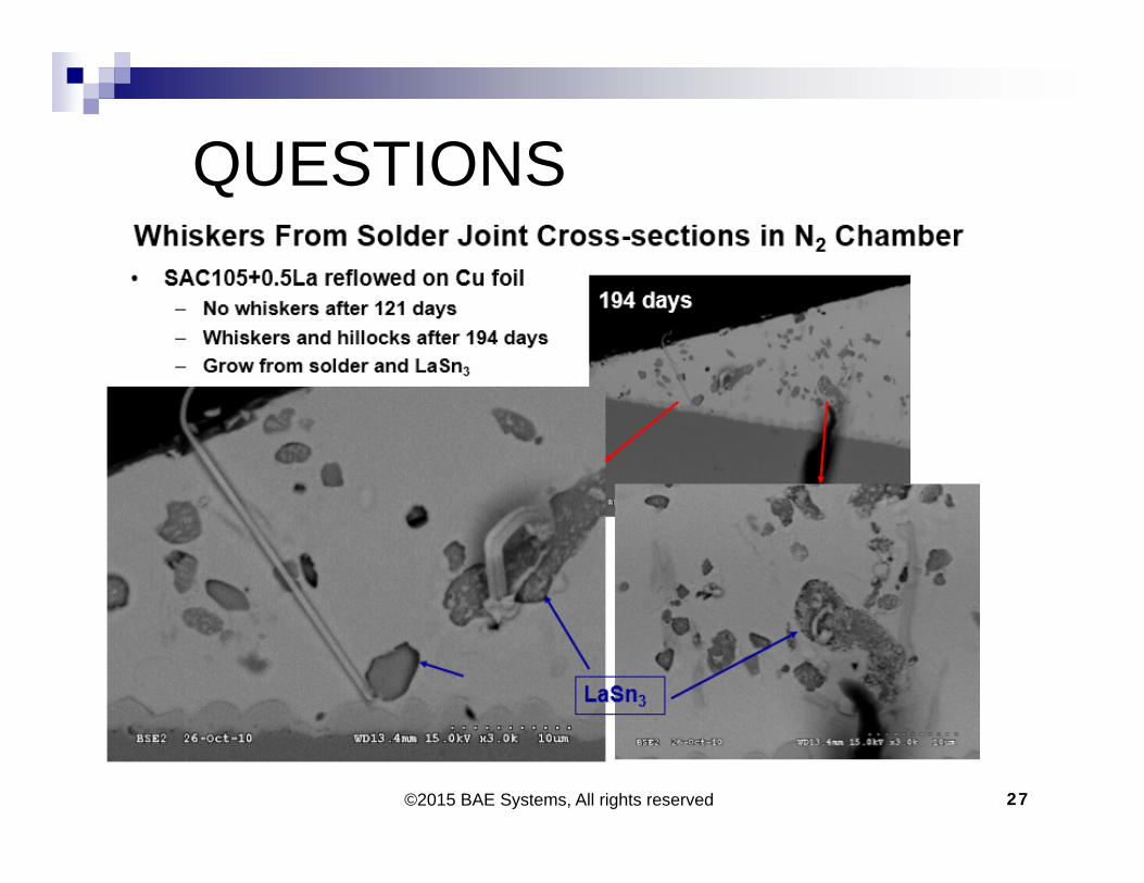
©2015 BAE Systems, All rights reserved 27
QUESTIONS
©2015 BAE Systems, All rights reserved
For more information contact
Dr. Stephan MeschterBAE Systems, Endicott, NY
(607) 770-2332 [email protected]
28
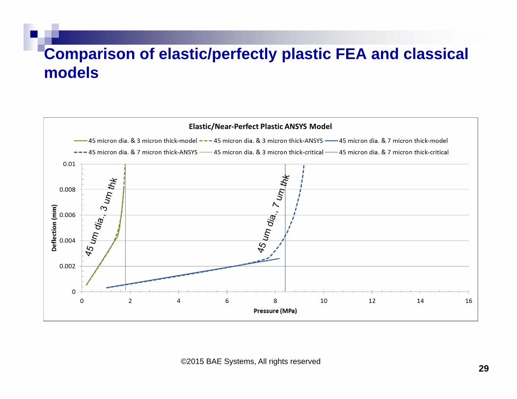
Comparison of elastic/perfectly plastic FEA and classical models
29©2015 BAE Systems, All rights reserved
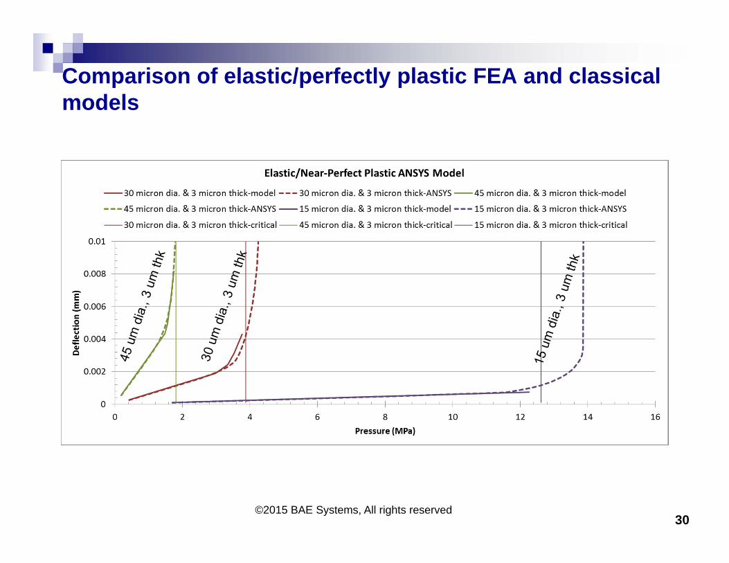
Comparison of elastic/perfectly plastic FEA and classical models
30©2015 BAE Systems, All rights reserved