strain analysis · · 2009-03-30ii strain dept. of geology strain analysis ... ii strain dept. of...
TRANSCRIPT
II Strain
Dept. of Geology
STRAIN ANALYSIS
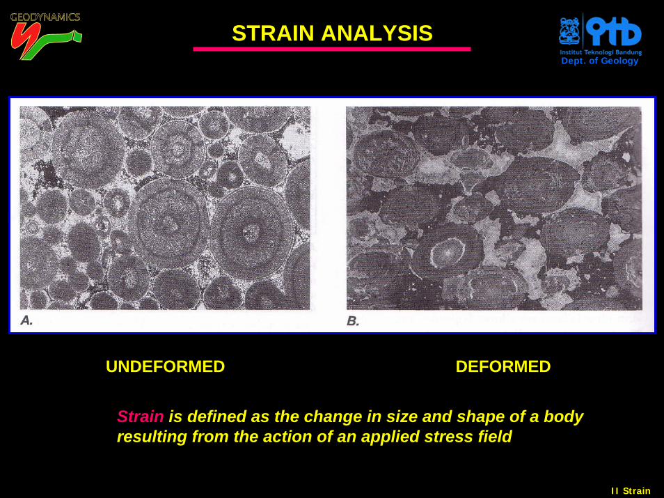
UNDEFORMED DEFORMED
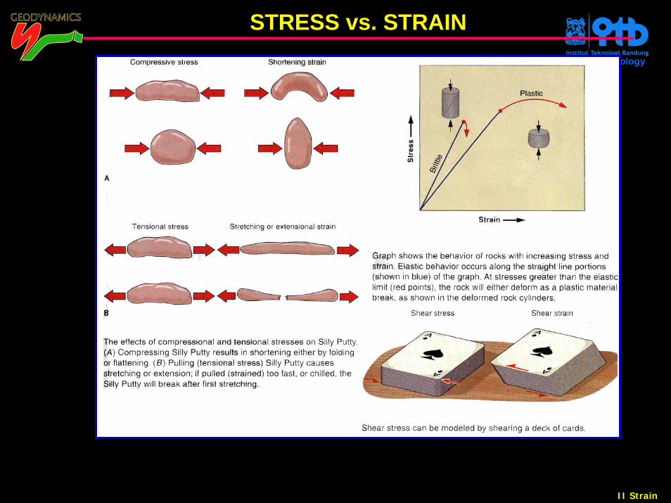
Strain is defined as the change in size and shape of a body resulting from the action of an applied stress field
II Strain
Dept. of Geology
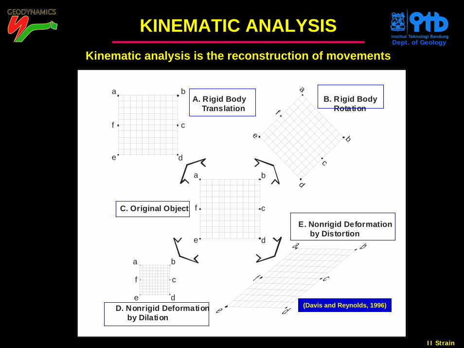
KINEMATIC ANALYSISKinematic analysis is the reconstruction of movements
cf
a
cde
ba
cf
A. Rigid Body Translation
ba
f
d
e b
a
B. Rigid Body Rotation
E. Nonrigid Deformation by Distortion
C. Original Object
c
e
b
e d
f c
d ad
f
e
b
D. Nonrigid Deformation by Dilation
(Davis and Reynolds, 1996)
II Strain
Dept. of Geology
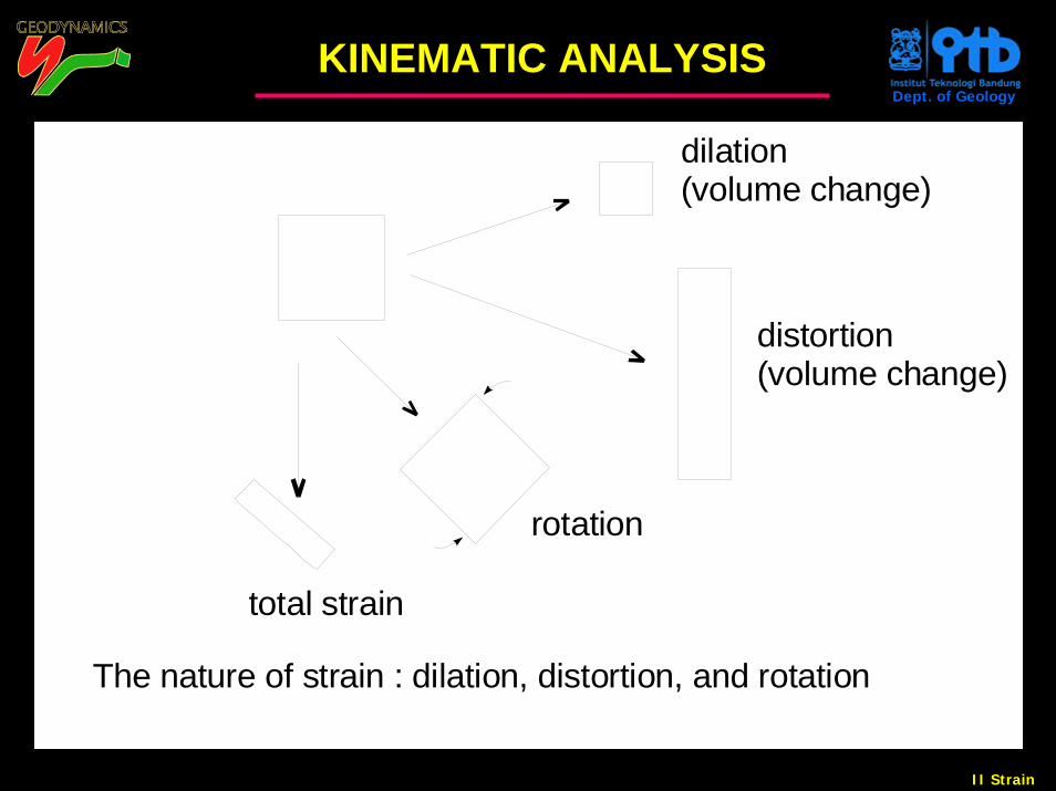
(volume change)
The nature of strain : dilation, distortion, and rotation
(volume change)dilation
distortion
total strain
rotation
KINEMATIC ANALYSIS
II Strain
Dept. of Geology
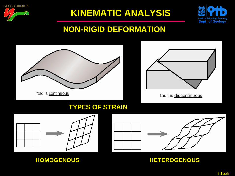
NON-RIGID DEFORMATION
HOMOGENOUS HETEROGENOUS
TYPES OF STRAIN
KINEMATIC ANALYSIS
II Strain
Dept. of Geology
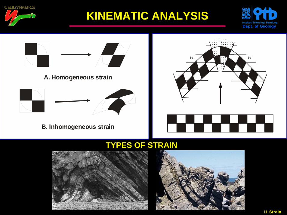
B. Inhomogeneous strain
A. Homogeneous strain
H
I
H
TYPES OF STRAIN
KINEMATIC ANALYSIS
II Strain
Dept. of Geology
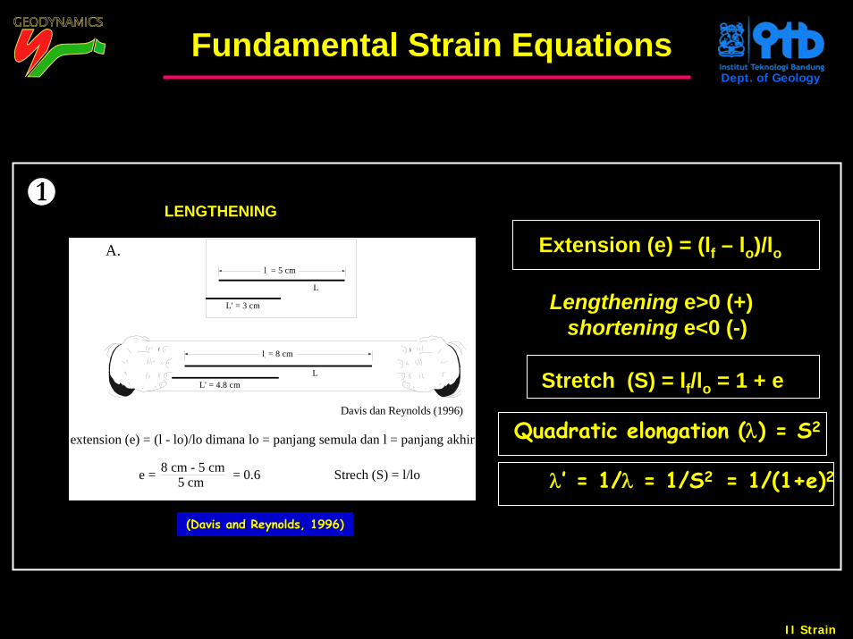
A.
L
l = 5 cmo
L' = 3 cm
L
l = 8 cmf
Davis dan Reynolds (1996)
L' = 4.8 cm
8 cm - 5 cm 5 cm Strech (S) = l/lo e = = 0.6
extension (e) = (l - lo)/lo dimana lo = panjang semula dan l = panjang akhir
Extension (e) = (lf – lo)/lo
Stretch (S) = lf/lo = 1 + e
Lengthening e>0 (+) shortening e<0 (-)
LENGTHENING1
Fundamental Strain Equations
(Davis and Reynolds, 1996)(Davis and Reynolds, 1996)
Quadratic elongation (λ) = S2
λ’ = 1/λ = 1/S2 = 1/(1+e)2
II Strain
Dept. of Geology
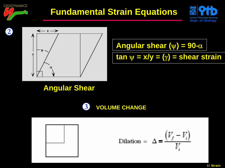
Angular shear (ψ) = 90-αtan ψ = x/y = (γ) = shear strain
VOLUME CHANGE
Angular Shear
2
3
Fundamental Strain Equations
II Strain
Dept. of Geology
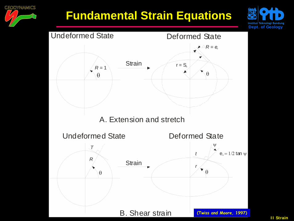
Strain
B. Shear strain
Deformed State
Strain
R e = n
Deformed State
Undeformed State
A. Extension and stretch
Undeformed State
R = 1θ
θr
θ
θ
r = Sn
T
Re tans = 1/2 ψt
ψ
((TwissTwiss and Moore, 1997)and Moore, 1997)
Fundamental Strain Equations
II Strain
Dept. of Geology
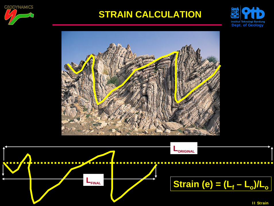
STRAIN CALCULATION
LLORIGINALORIGINAL
LLFINALFINAL Strain (e) = (Lf – Lo)/Lo
II Strain
Dept. of Geology
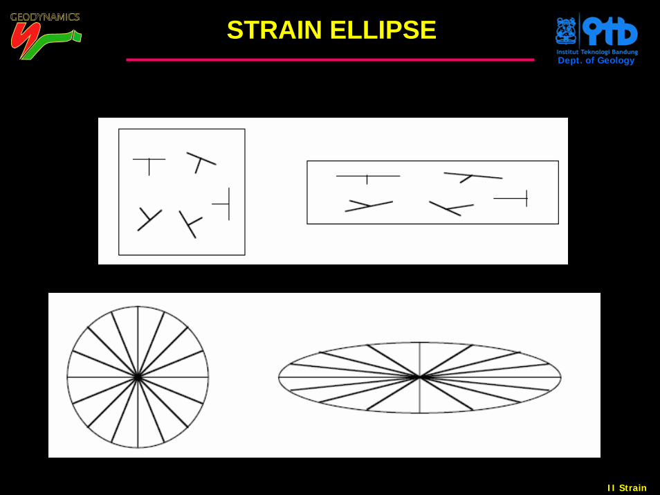
STRAIN ELLIPSE
II Strain
Dept. of Geology
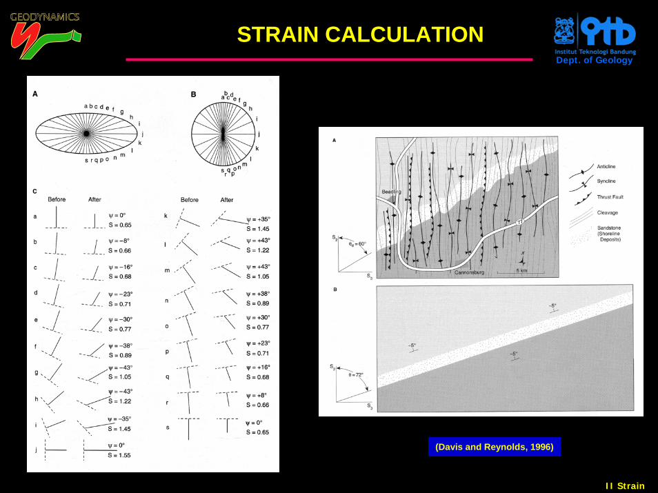
(Davis and Reynolds, 1996)
STRAIN CALCULATION
II Strain
Dept. of Geology
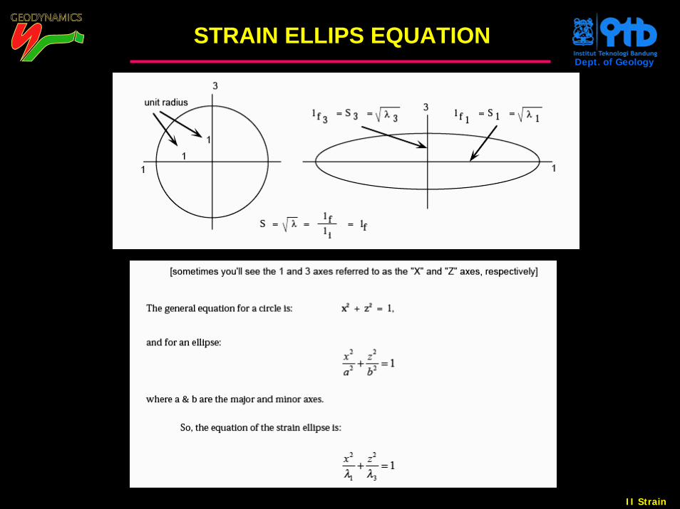
STRAIN ELLIPS EQUATION
II Strain
Dept. of Geology
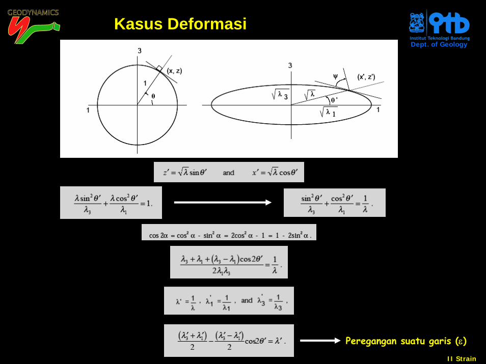
Kasus Deformasi
Peregangan suatu garis (ε)
II Strain
Dept. of Geology
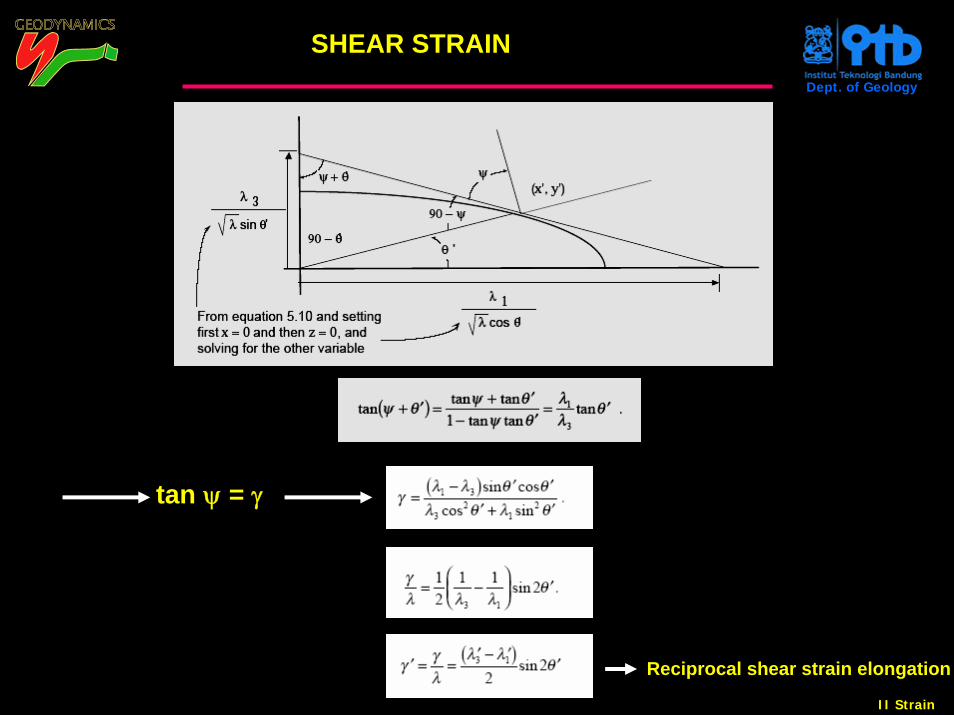
SHEAR STRAIN
tan ψ = γ
Reciprocal shear strain elongation
II Strain
Dept. of Geology
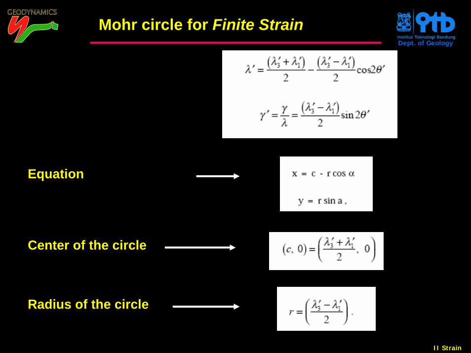
Mohr circle for Finite Strain
Equation
Center of the circle
Radius of the circle
II Strain
Dept. of Geology
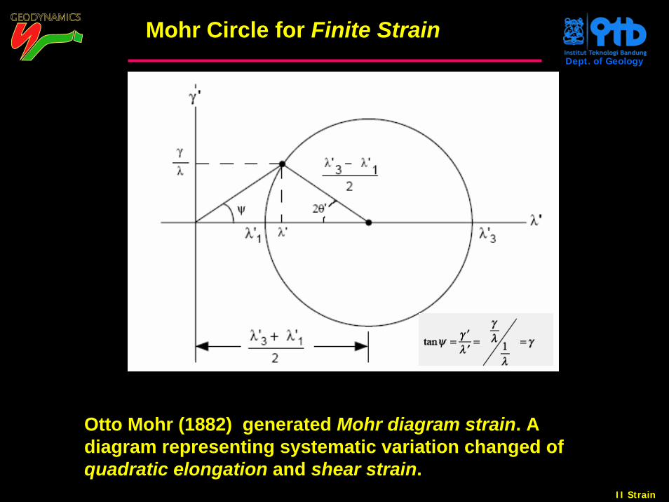
Mohr Circle for Finite Strain
Otto Mohr (1882) generated Mohr diagram strain. A diagram representing systematic variation changed of quadratic elongation and shear strain.
II Strain
Dept. of Geology
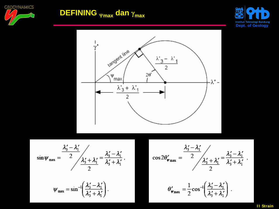
DEFINING Ψmax dan γmax
II Strain
Dept. of Geology
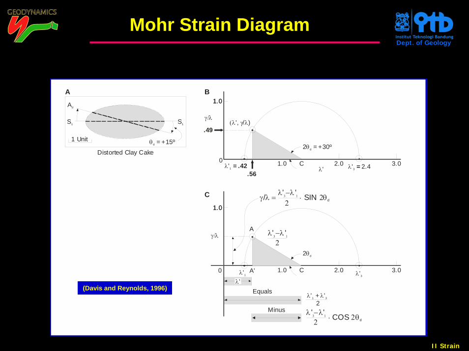
Mohr Strain Diagram
Ad
θd = +15º
C
λ'3
Distorted Clay Cake
S1
1 Unit
A
S1
3.0
γ/λ
Minus
1.01.0
C
2 θd
λ −λ
2' '3 1
λ λ' + ' 2
1 3
2.01.0
B
λ'3.0
.56
γ/λ
.49
0
1.01.0
C
2 = +30ºθd
(λ γ λ', / )
λ' 2.43 = λ'1 = .42 2.01.0
λ −λ . 2θ2
' ' COS 3 1 d
0
A
A'λ'1
Equals
γ λ = λ −λ . 2θ
2/ ' ' SIN 3 1
d
λ'(Davis and Reynolds, 1996)
II Strain
Dept. of Geology
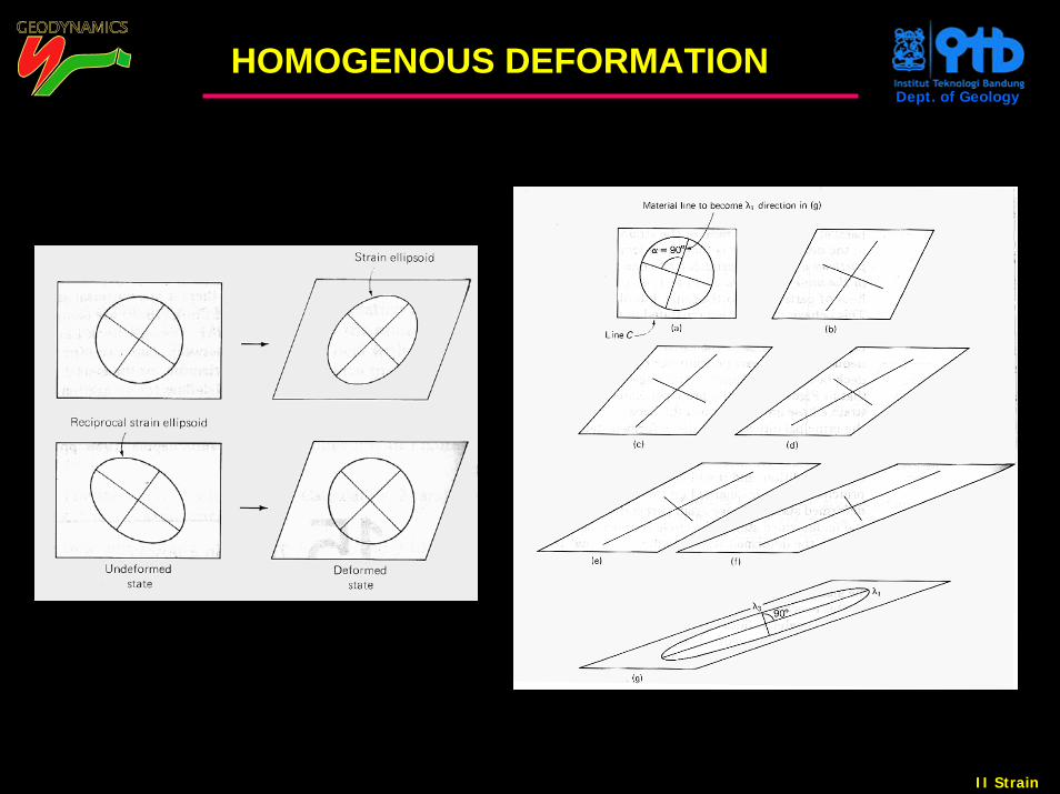
HOMOGENOUS DEFORMATION
II Strain
Dept. of Geology
O
N
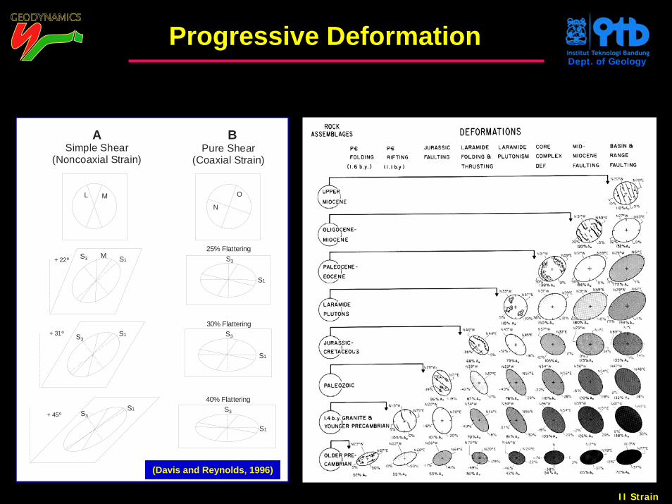
Simple Shear(Noncoaxial Strain)
A B
M
S1
ML
Pure Shear(Coaxial Strain)
S3S3
S1
25% FlatteringS3
S1
S3 S1+ 22º
+ 31º S3S1
S1
S3
30% Flattering
+ 45º
40% Flattering
Progressive Deformation
(Davis and Reynolds, 1996)
II Strain
Dept. of Geology
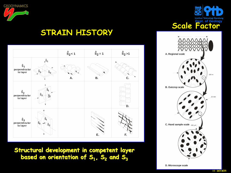
D. Microscope scale
100 mμ
A. Regional scale
100 m
B. Outcrop scale
10 mm
C. Hand sample scale
D.
A.
perpendicu larto layer
perpendicu larto layer
perpendicu larto layer
E.
C.
F.
B.
^^
S1
S2S3
S1^
^
^ ^ ^
^
S1^
S1^
S2^
S2^
S2S3^
S3^
S3
S2 < 1 S2 = 1 S2 >1
STRAIN HISTORY
Structural development in competent layerStructural development in competent layerbased on orientation of Sbased on orientation of S11, S, S22 and Sand S33
Scale Factor
II Strain
Dept. of Geology
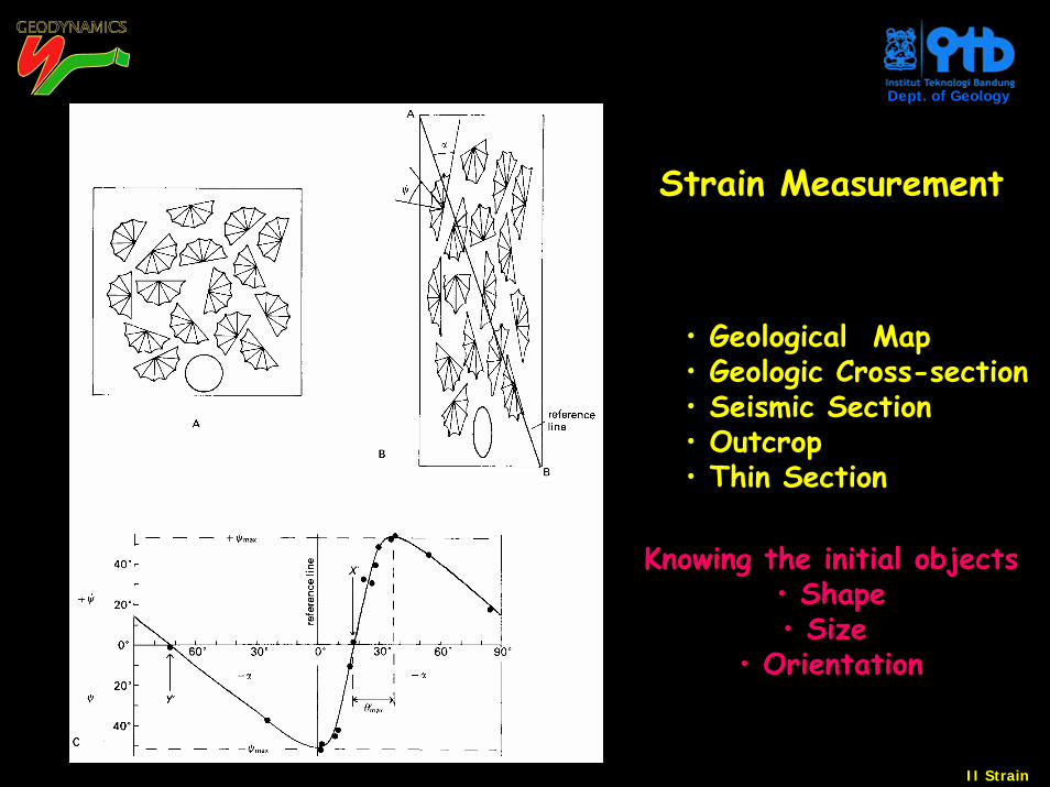
Strain Measurement
• Geological Map • Geologic Cross-section• Seismic Section• Outcrop• Thin Section
Knowing the initial objects• Shape• Size
• Orientation
II Strain
Dept. of Geology
S2
S2S3
S3
S3
S1
S1
S1
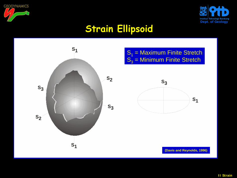
Strain Ellipsoid
S1 = Maximum Finite StretchS3 = Minimum Finite Stretch
(Davis and Reynolds, 1996)
II Strain
Dept. of Geology
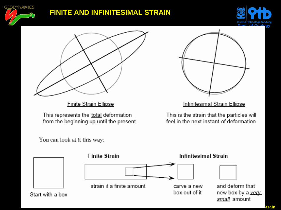
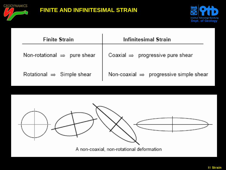
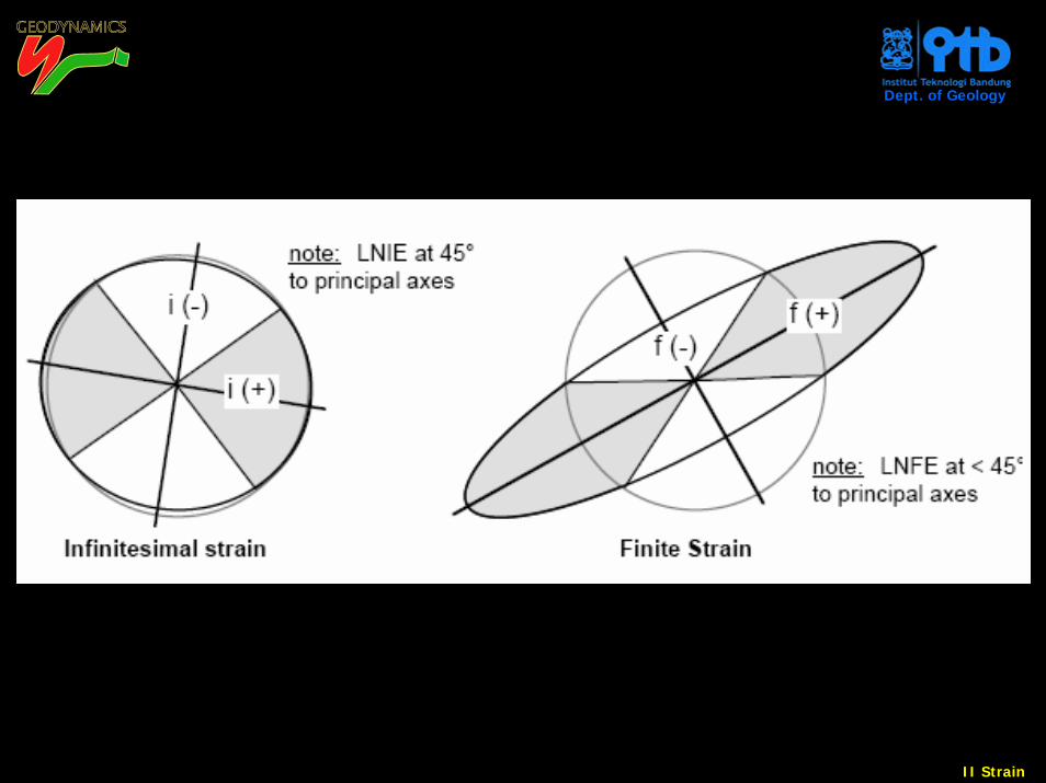
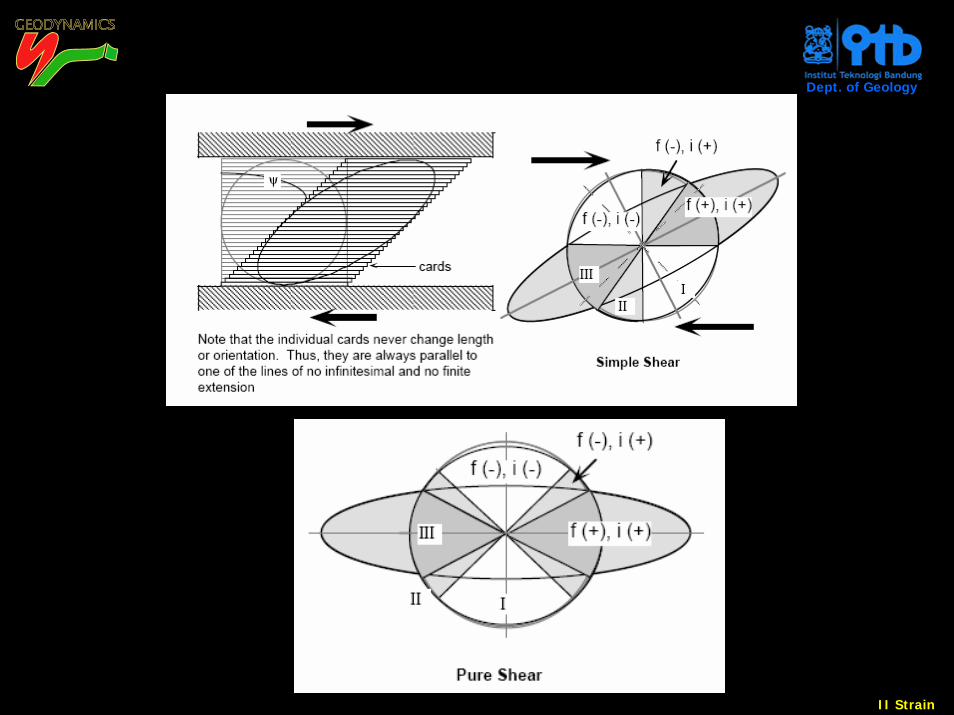
FINITE AND INFINITESIMAL STRAIN
II Strain
Dept. of Geology
FINITE AND INFINITESIMAL STRAIN
II Strain
Dept. of Geology
II Strain
Dept. of Geology
II Strain
Dept. of Geology
II Strain
Dept. of Geology
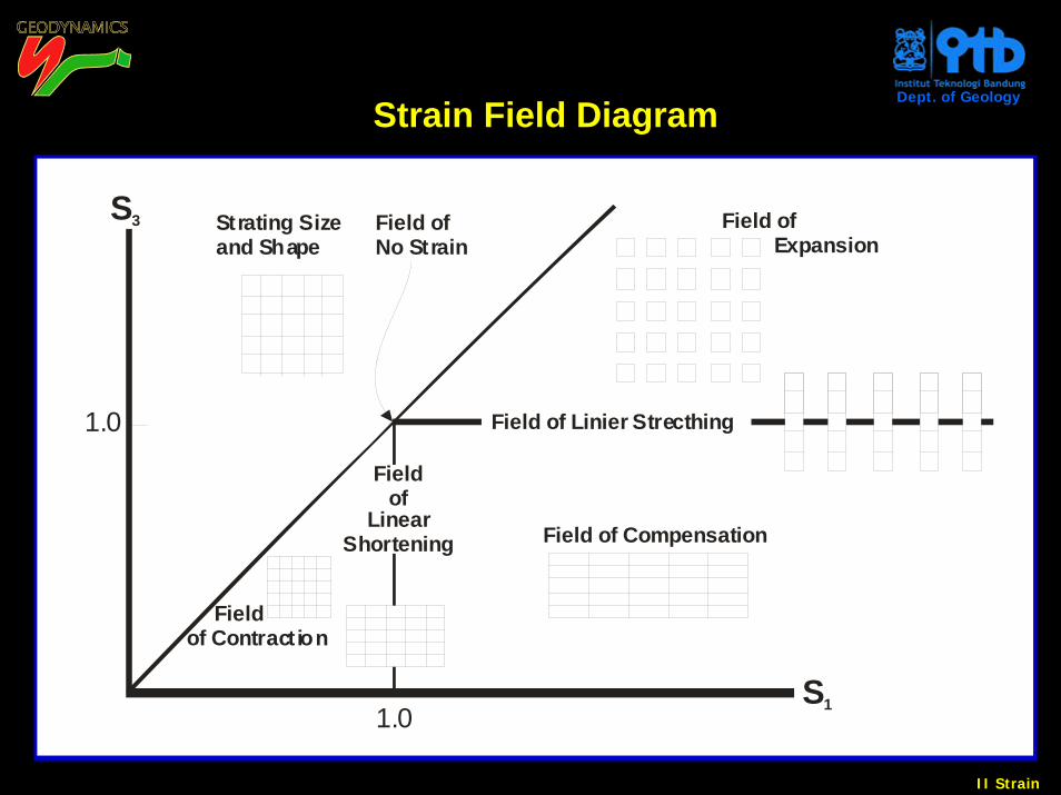
Field of Compensation
Field of Expansion
1.0
Field ofNo Strain
Strating Sizeand Shape
Fieldof
LinearShortening
Field of Contraction
S1
1.0
S3
Field of Linier Strecthing
Strain Field Diagram
II Strain
Dept. of Geology
X
Z
Y
Z
X
Y
A
Z
Y
X
B
^1
b = S
S2
3^
^a =
SS
1
2^
K = 1
K = 0
ConstrictionalStrain
FlatteringStrain
Plane S
train
Sim
ple
Ext
ensi
on
Simple Flattering1
k = χ
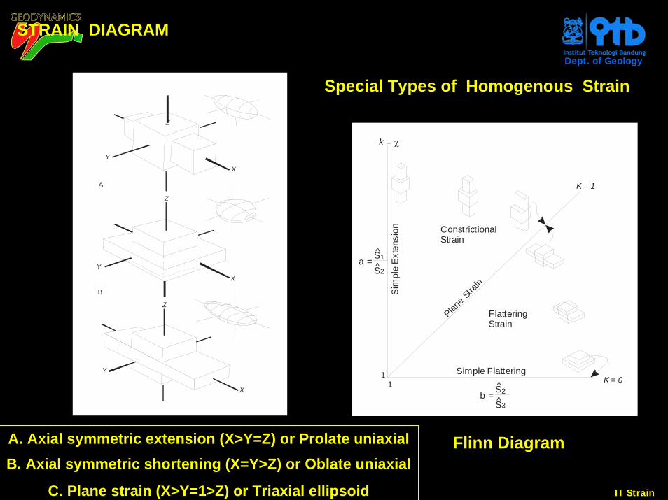
Special Types of Homogenous Strain
A. Axial symmetric extension (X>Y=Z) or Prolate uniaxialB. Axial symmetric shortening (X=Y>Z) or Oblate uniaxial
C. Plane strain (X>Y=1>Z) or Triaxial ellipsoid
Flinn Diagram
STRAIN DIAGRAM
II Strain
Dept. of Geology
S2
S2S3
S3
S3
S1
S1
S1
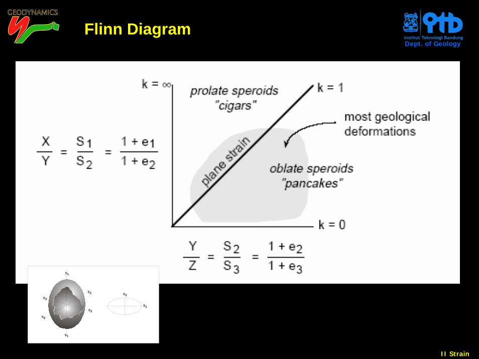
Flinn Diagram
II Strain
Dept. of Geology
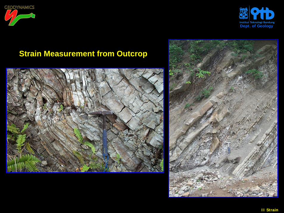
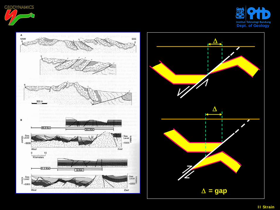
Strain Measurement from Outcrop
II Strain
Dept. of Geology
Δ = gap
Δ
Δ
II Strain
Dept. of Geology
STRESS vs. STRAIN
II Strain
Dept. of Geology
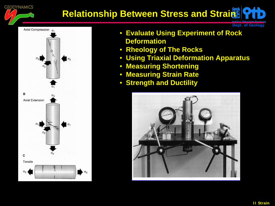
Relationship Between Stress and Strain
• Evaluate Using Experiment of Rock Deformation
• Rheology of The Rocks• Using Triaxial Deformation Apparatus• Measuring Shortening• Measuring Strain Rate • Strength and Ductility
II Strain
Dept. of Geology
2 3 4 61
C
Strain (in %)
Diffe
rent
ial S
tress
(in
MP
a)
ReptureStrength
400
5
100
200
300Yield
Strength
UltimateStrength
Yield StrengthAfter StrainHardening D
A
EB
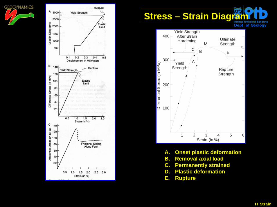
Stress – Strain Diagram
A. Onset plastic deformationB. Removal axial loadC. Permanently strained D. Plastic deformationE. Rupture
II Strain
Dept. of Geology
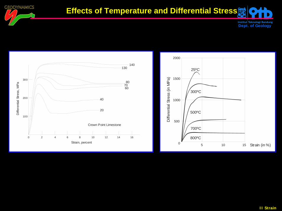
0 2 4 6 8 10 12 14 16
Diff
eren
tial S
tress
, MPa
Strain, percent
300
200
100
70
20
Crown Point Limestone
40
140130
60
80
5 10 15
2000
1500
1000
0 Strain (in %)
800ºC
700ºC
500ºC
300ºC
500Diff
eren
tial S
tress
(in
MP
a)
25ºC
Effects of Temperature and Differential Stress
II Strain
Dept. of Geology
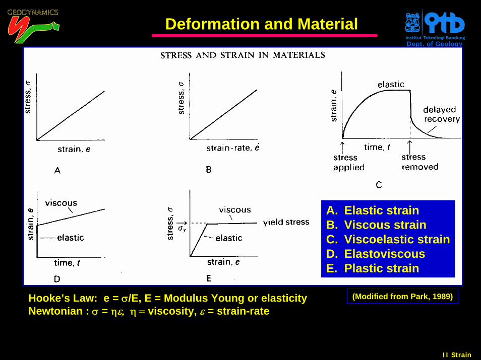
(Modified from Park, 1989)
Deformation and Material
A. Elastic strainB. Viscous strainC. Viscoelastic strainD. ElastoviscousE. Plastic strain
Hooke’s Law: e = σ/E, E = Modulus Young or elasticityNewtonian : σ = ηε, η = viscosity, ε = strain-rate
II Strain
Dept. of Geology
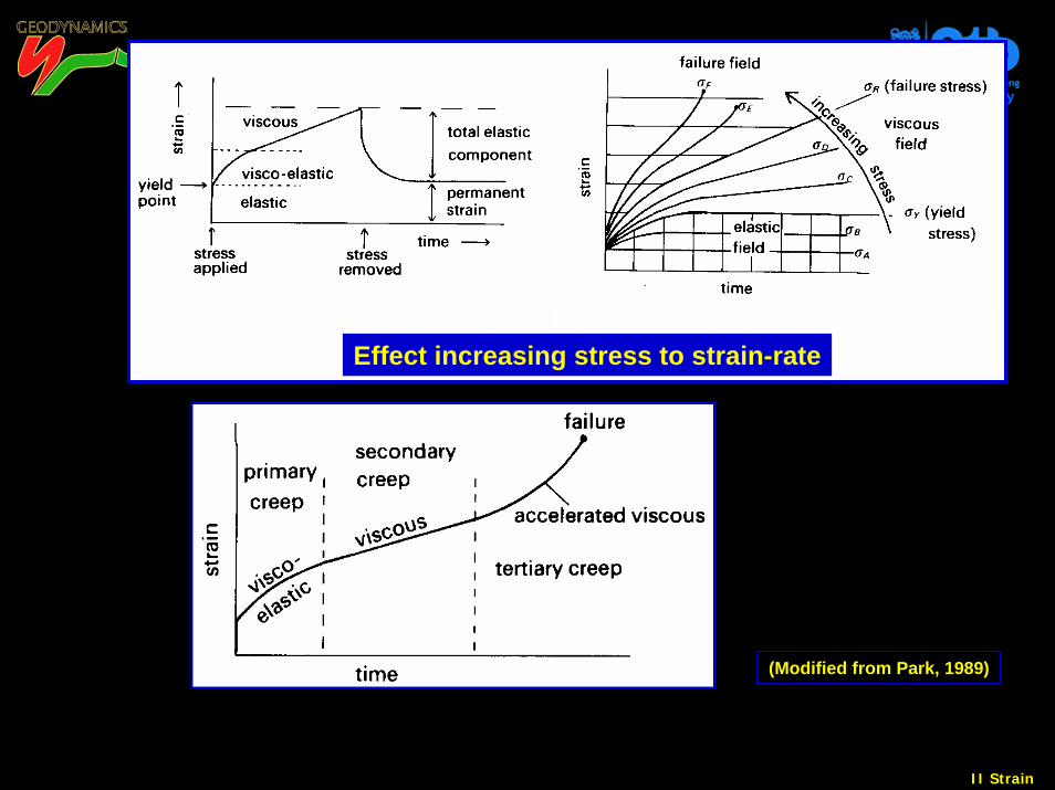
(Modified from Park, 1989)
Effect increasing stress to strain-rate
II Strain
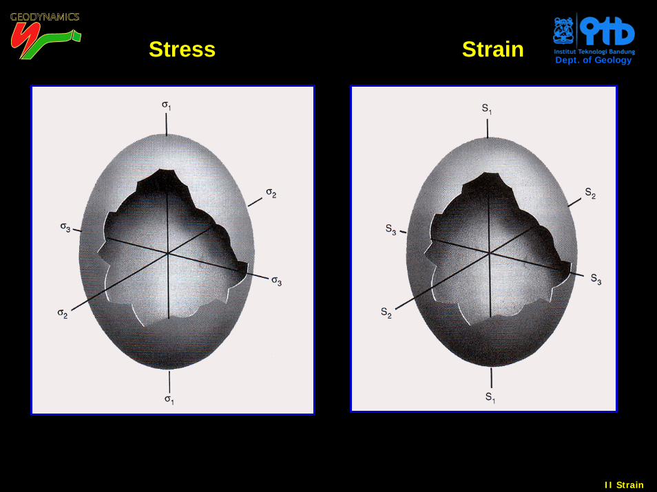
Dept. of GeologyStress Strain
II Strain
Dept. of Geology
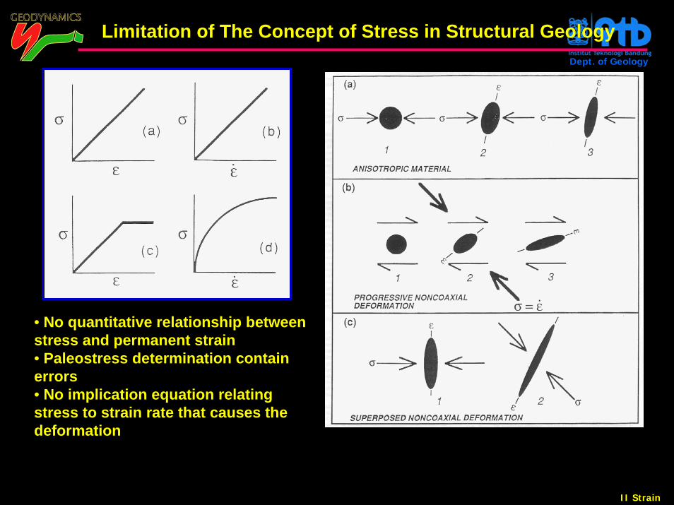
Limitation of The Concept of Stress in Structural Geology
• No quantitative relationship between stress and permanent strain• Paleostress determination contain errors• No implication equation relating stress to strain rate that causes the deformation