storage networking interfaces
TRANSCRIPT
VERSION UPDATED: 11/2014

Demartek
ABOUT THIS REPORT
LEGENDINFOHover over this symbol to view additionalinformation about a specific topic
SEARCHAllows you to search for a specificword within the document
ACRONYM SHORTCUTProvides definitions to technical abreviationslisted on the page upon hover
NEXTAdvances to the next page
LASTReturns to the previous page
PRINTProvides print options for the document
CLOSECloses the window containing this icon
Because of the number of storage interface types and relatedtechnologies that are used for storage devices, we havecompiled this summary document providing some basicinformation for each of the interfaces. This document will beupdated periodically. This document may become larger over time. Contact us if you’d like to see additional information in this document.
The interface types listed here are known as “block” interfaces, meaning that they provide an interface for “block” reads and writes. They simply provide a conduit for blocks of data to be read and written, without regard to file systems, file names or any other knowledge of the data in the blocks. The host requesting the block access provides a starting address and number of blocks to read or write.
We are producing deployment guides for some of thetechnologies described in this document.
This version of the Demartek Storage Interface Comparison report is provided inan active PDF format. With this format you are capable of viewing and interacting with the information in ways not available with standard PDF readers. To get themost out of this guide we encourage you to upgrade to the latest version of theAdobe Acrobat Reader.
Demartek provides real-world, hands-on research and analysis by focusing onindustry analysis and lab validation testing of server, network, storage andsecurity technologies.
Demartek provides a few handy reference documents based on workperformed in the Demartek Lab. These documents are updated periodically.To get more information visit:
Demartek
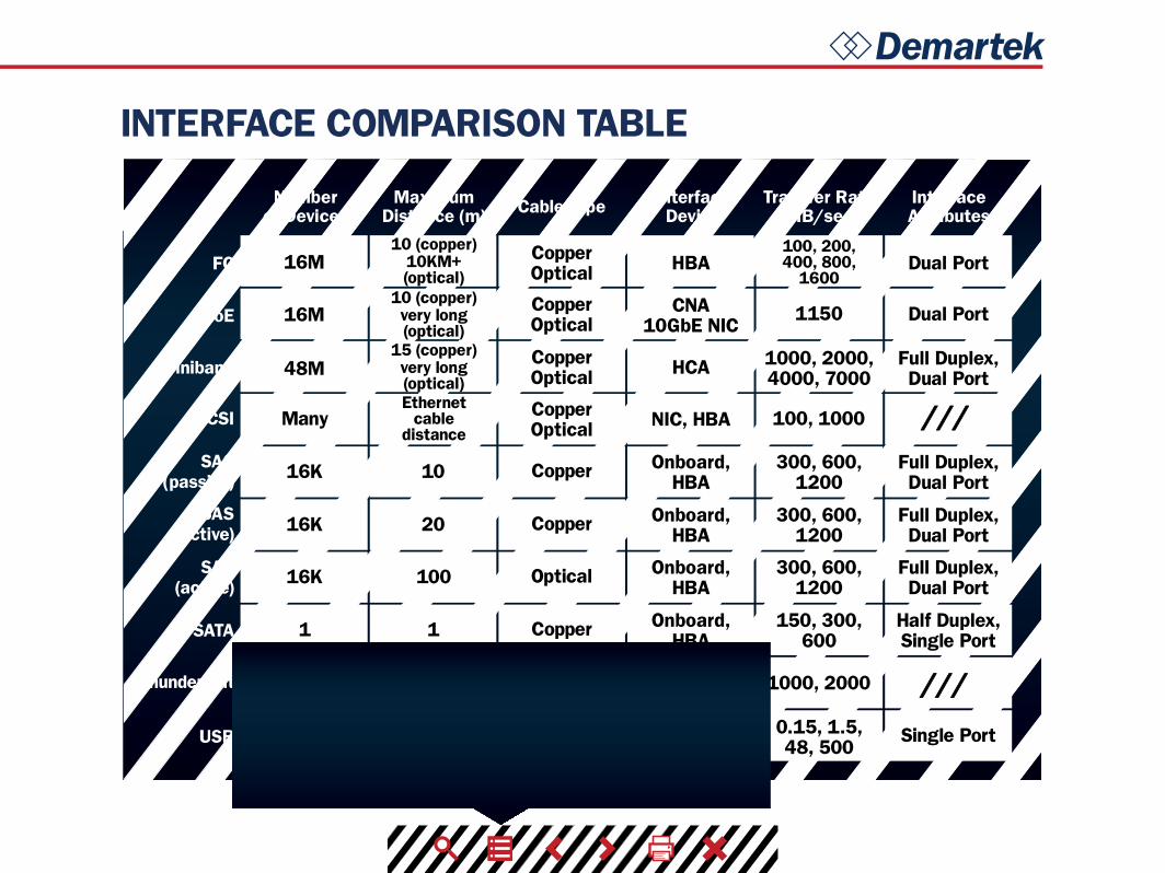
INTERFACE COMPARISON TABLE
Numberof Devices
MaximumDistance (m)
InterfaceDevice
Transfer Rate(MB/sec)
InterfaceAttributesCable Type
FC
FCoE
Infiniband
iSCSI
SAS(passive)
SAS(active)
SAS(active)
SATA
USB
16M
1150
100, 1000
CopperOptical HBA Dual Port
Dual PortCNA10GbE NIC
HCA
NIC, HBA
Onboard,HBA
Onboard,HBA
Onboard,HBA
Onboard,HBA
CopperOptical
CopperOpticalCopperOptical
1000, 2000,4000, 7000
Full Duplex,Dual Port
Full Duplex,Dual Port
Full Duplex,Dual Port
Full Duplex,Dual Port
Half Duplex,Single Port
300, 600,1200
300, 600,1200
300, 600,1200
150, 300,600
Copper
Copper
Optical
Copper
10 (copper)10KM+(optical)
10 (copper)very long(optical)
15 (copper)very long(optical)Ethernet
cabledistance
100, 200,400, 800,
1600
16M
16K 10
20
100
1
16K
16K
1
Single Port0.15, 1.5,48, 500
Copper,Wireless
Onboard,Adapter
card5127
48M
Many
Thunderbolt 6 4 Copper Onboard 1000, 2000FC - Fibre ChannelFCoE - Fibre Channel over EthernetIB - InfinibandiSCSI - Internet Small Computer System InterfaceNVMe - NVM ExpressPCIe - PCI ExpressSAS - Serial Attached SCSISATA - Serial ATAUSB - Universal Serial Bus
10GbE - 10 Gigabit EthernetCNA - Converged Network AdapterHBA - Host Bus AdapterHCA - Host Channel AdapterNIC - Network Interfaced Controller
MB/s - Megabytes per second
///
///
Demartek
TRANSFER RATE
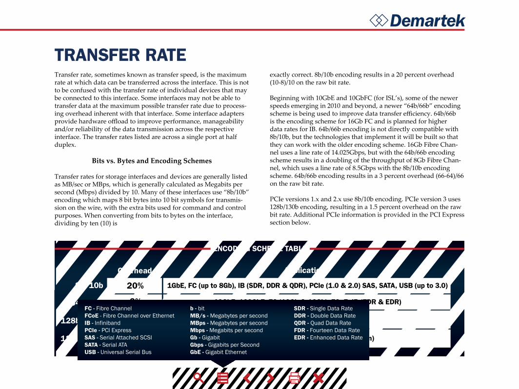
ENCODING SCHEME TABLE
Transfer rate, sometimes known as transfer speed, is the maximum rate at which data can be transferred across the interface. This is not to be confused with the transfer rate of individual devices that may be connected to this interface. Some interfaces may not be able to transfer data at the maximum possible transfer rate due to process-ing overhead inherent with that interface. Some interface adapters provide hardware offload to improve performance, manageability and/or reliability of the data transmission across the respective interface. The transfer rates listed are across a single port at half duplex.
Bits vs. Bytes and Encoding Schemes
Transfer rates for storage interfaces and devices are generally listed as MB/sec or MBps, which is generally calculated as Megabits per second (Mbps) divided by 10. Many of these interfaces use “8b/10b” encoding which maps 8 bit bytes into 10 bit symbols for transmis-sion on the wire, with the extra bits used for command and control purposes. When converting from bits to bytes on the interface, dividing by ten (10) is
exactly correct. 8b/10b encoding results in a 20 percent overhead (10-8)/10 on the raw bit rate.
Beginning with 10GbE and 10GbFC (for ISL’s), some of the newer speeds emerging in 2010 and beyond, a newer “64b/66b” encoding scheme is being used to improve data transfer efficiency. 64b/66b is the encoding scheme for 16Gb FC and is planned for higher data rates for IB. 64b/66b encoding is not directly compatible with 8b/10b, but the technologies that implement it will be built so that they can work with the older encoding scheme. 16Gb Fibre Chan-nel uses a line rate of 14.025Gbps, but with the 64b/66b encoding scheme results in a doubling of the throughput of 8Gb Fibre Chan-nel, which uses a line rate of 8.5Gbps with the 8b/10b encoding scheme. 64b/66b encoding results in a 3 percent overhead (66-64)/66 on the raw bit rate.
PCIe versions 1.x and 2.x use 8b/10b encoding. PCIe version 3 uses 128b/130b encoding, resulting in a 1.5 percent overhead on the raw bit rate. Additional PCIe information is provided in the PCI Express section below.
8b/10b
64b/66b
128b/130b
128b/132b
Overhead Applications
20% 1GbE, FC (up to 8Gb), IB (SDR, DDR & QDR), PCIe (1.0 & 2.0) SAS, SATA, USB (up to 3.0)
10GbE, 100GbE, FC (10Gb & 16Gb), FCoE, IB (FDR & EDR)
PCIe 3.0, 24Gb SAS (likely)
USB 3.1 (10Gbps, see Roadmaps section)
1.5%
3%
3%
FC - Fibre ChannelFCoE - Fibre Channel over EthernetIB - InfinibandPCIe - PCI ExpressSAS - Serial Attached SCSISATA - Serial ATAUSB - Universal Serial Bus
SDR - Single Data RateDDR - Double Data Rate QDR - Quad Data RateFDR - Fourteen Data RateEDR - Enhanced Data Rate
b - bitMB/s - Megabytes per secondMBps - Megabytes per secondMbps - Megabits per secondGb - GigabitGbps - Gigabits per SecondGbE - Gigabit Ethernet

DemartekTRANSFER RATE (cont.)
FIBER CHANNEL SPEED TABLE
INFINIBAND SPEED TABLE
PCI-X
PCI-X
PCIe 3.0 x8
PCI-X 2.0 orPCIe 1.0 x4
PCI-X 1.0 x8 orPCIe 2.0 x4
PCI-X 2.0 x8 orPCIe 3.0 x4
8b/10b
8b/10b
8b/10b
8b/10b
64b/66b
64b/66b
1.0625
2.125
4.25
8.5
14.025
28.05
100
2Gbps
4Gbps
8Gbps
8Gbps 24Gbps 8b/10b PCIe 1.0 x8PCIe 1.0 x16 or
PCIe 2.0 x8
PCIe 2.0 x8
PCIe 3.0 x8
PCIe 3.0 x8
PCIe 3.0 x16
8b/10b
8b/10b
64b/66b
64b/66b
64b/66b
48Gbps
96Gbps
123.75Gbps
163.64Gbps
300Gbps
16Gbps
32Gbps
41.25Gbps
54.55Gbps
100Gbps
10.31Gbps
13.64Gbps
25Gbps
200
400
800
1600
3200
1GFC
2GFC
4GFC
8GFC
16GFC
32GFC
Throughput(MBps)
1X data rate 4X data rate 12X data rate
Line Rate(GBaud)
Host Adapter req.(dual-port cards)
Host Adapter req.(dual-port cards)
Encoding
Encoding
SDR
DDR
QDR
FDR
EDR
FDR-10*
Mellanox only*
GFC - Gigabit Fibre ChannelGBaud - One Billion Bits of Data/SecondPCIe - PCI ExpressPCI-X - PCI eXtended
SDR - Single Data RateDDR - Double Data Rate QDR - Quad Data RateFDR - Fourteen Data RateEDR - Enhanced Data Rate
b - bitMBps - Megabytes per secondGbps - Gigabits per second
Demartek
HISTORY
Click interface above to view history
*for more detailed information refer to the “Roadmaps” page
Fibre ChannelFibre Channel (ISL only)
1Gbps 2Gbps 4Gbps
10Gbps
8Gbps 16Gbps
16GFC HBAsannounced
16GFC storageexpected 32GFC specs
expected
‘97 ‘98 ‘99 ‘00 ‘01 ‘02 ‘03 ‘04 ‘05 ‘06 ‘07 ‘08 ‘09 ‘10 ‘11 ‘12 ‘13 ‘14 ‘15
*for more detailed information refer to the “Roadmaps” page
FC: 4Gbps and Ethernet 10GbpsFCoE 10Gbps
‘97 ‘98 ‘99 ‘00 ‘01 ‘02 ‘03 ‘04 ‘05 ‘06 ‘07 ‘08 ‘09 ‘10 ‘11 ‘12 ‘13 ‘14 ‘15
*for more detailed information refer to the “Roadmaps” page
Infiniband
10Gbps 20Gbps 40Gbps 56Gbps‘97 ‘98 ‘99 ‘00 ‘01 ‘02 ‘03 ‘04 ‘05 ‘06 ‘07 ‘08 ‘09 ‘10 ‘11 ‘12 ‘13 ‘14 ‘15
iSCSIBasic 10GbEintroduced
1Gbps 10Gbps
*for more detailed information refer to the “Roadmaps” page
‘97 ‘98 ‘99 ‘00 ‘01 ‘02 ‘03 ‘04 ‘05 ‘06 ‘07 ‘08 ‘09 ‘10 ‘11 ‘12 ‘13 ‘14 ‘15
*for more detailed information refer to the “Roadmaps” page
NVMeVersion 1.0 spec published
Version 1.1 spec finalized
Version 1.2spec released
‘97 ‘98 ‘99 ‘00 ‘01 ‘02 ‘03 ‘04 ‘05 ‘06 ‘07 ‘08 ‘09 ‘10 ‘11 ‘12 ‘13 ‘14 ‘15
*for more detailed information refer to the “Roadmaps” page
SAS
3Gbps‘97 ‘98 ‘99 ‘00 ‘01 ‘02 ‘03 ‘04 ‘05 ‘06 ‘07 ‘08 ‘09 ‘10 ‘11 ‘12 ‘13 ‘14 ‘15
6Gbps 12Gbps
*for more detailed information refer to the “Roadmaps” page
SATA*traditional SATA is not expected to extend beyond 6Gbps
‘97 ‘98 ‘99 ‘00 ‘01 ‘02 ‘03 ‘04 ‘05 ‘06 ‘07 ‘08 ‘09 ‘10 ‘11 ‘12 ‘13 ‘14 ‘15
1.5Gbps 3Gbps
SATA SSD introduced
SATA Revisions 3.2
6Gbps
*for more detailed information refer to the “Roadmaps” page
USB
5Gbps480Mbps1.5Mbps 12Mbps
‘97 ‘98 ‘99 ‘00 ‘01 ‘02 ‘03 ‘04 ‘05 ‘06 ‘07 ‘08 ‘09 ‘10 ‘11 ‘12 ‘13 ‘14 ‘15
*for more detailed information refer to the “Roadmaps” page
‘97 ‘98 ‘99 ‘00 ‘01 ‘02 ‘03 ‘04 ‘05 ‘06 ‘07 ‘08 ‘09 ‘10 ‘11 ‘12 ‘13 ‘14 ‘15
Thunderbolt
10 Gbps 20 Gbps
The computing and storage industry is one that is moving at a rate that is often times is hard to keep up with. Every year, it seems, a new technology is released that often outshines the previous model many times over. Newer interface speeds are often available in switches and adapters long before they are available in storage devices and storage systems for public use.
We have created an interactive way to experience the rate of change for many different technologies. To view a timeline history and additional details of each type of interface, click on the inter-face name on the top of the graphic.
The graphics below are intended to show the interface history, not revenue, units shipped, or any other statistics.
FC - Fibre ChannelFCoE - Fibre Channel over EthernetIB - InfinibandiSCSI - Internet Small ComputerSystems InterfaceNVMe - Non-Volatile Memory ExpressPCIe - PCI ExpressSAS - Serial Attached SCSISATA - Serial ATAUSB - Universal Serial Bus
GFC - Gigabyte Fibre ChannelGbps - Gigabits per secondGbE - Gigabit EthernetMbps - Megabits per Second
ISL - Inter-Switch LinkHBA - Host Bus Adapter

Demartek
ROADMAPS
Click interface above to view roadmap
1 2 3 4 1 2 3 41 2 1 2 3
In July 2014, two different industry groups announced new work on Ethernet specifications to take advantage of 25Gb PHYs in a single-lane configuration. This would result in a single-lane 25GbE connection similar to the existing 10GbE technology, running 2.5x faster. This has obvious implications for storage applications such as FCoE and iSCSI block protocols as well as other file and object protocols. End-user products using these technologies may become available in late 2015 or 2016. The two industry groups are the 25G/50G Ethernet Consortium and the IEEE 802.3 25Gb/s Ethernet Study Group. The 25G/50G Ethernet Consortium is working on single-lane 25GbE and dual-lane 50GbE solutions. See the Connector Types page for additional comments on single-lane and multi-lane connection technology.
Ethernet
These roadmaps include the estimated calendar years that higher speeds may become available and are based on our industry research, which are subject to change. Past history indicates that several of these interfaces are on a three or four year development cycle for the next improvement in speed. It is reasonable to expect that pace to continue.
It should be noted that it typically takes several months after the specification is complete before products are generally
available in the marketplace. Widespread adoption of those newproducts takes additional time, sometimes years.
Some of the standards groups are now working on “Energy Ef-ficient” versions of these interfaces to indicate additions to their standards to reduce power consumption. Additional information on NVMe is located on the Demartek NVMe Commentary page. For additional comments on Thunderbolt and USB, visit our CES2014 Commentary page or our Demartek IDF2014 Commentary page.
FC - Fibre ChannelFCoE - Fibre Channel over EthernetIB - InfinibandiSCSI - Internet Small ComputerSystems InterfaceNVMe - Non-Volatile Memory ExpressPCIe - PCI ExpressSAS - Serial Attached SCSISATA - Serial ATAUSB - Universal Serial Bus
SAN - Storage Area NetworkVN - Virtual Network EDR - Enhanced Data RateINCITS - International Committee forInformation Technology StandardsFCIA - Fibre Channel Industry Asso.
GFC - Gigabyte Fibre ChannelGbps - Gigabits per secondGbE - Gigabit EthernetMbps - Megabits per Second
1
Work on the 32Gbps FC (32GFC) standard, FC-PI-6, began in early 2010. In December 2013, the Fibre Channel Industry Association (FCIA) announced the completion of the PC-PI-6 specifica-tion. 32GFC products are expected to become available by 2015 or 2016. 32GFC is expected to use the 25/28G SFP+ connector technology as described in the connector section.
A multi-lane 128GFC interface, known as 128GFCp (parallel, four-lane), is based on the 32GFC work and has been added to the official Fibre Channel roadmap. The T11 committee has accepted this as a project known as FC-PI-6P. This specification is expected to be completed in late 2014 or early 2015, with products possibly available 2015 or 2016. 128GFCp will probably use QSFP+ connectors and may support CFP2 or CFP4 connectors.
Some vendors refer to 32GFC and 128GFC as “Gen 6” Fibre Channel since this version of Fibre Channel supports two different speeds, in two different configurations (serial and parallel).
32Gbps FC (32GFC)
2
Work has not yet begun in the T11 committee for developing the single-lane 64GFC specifica-tions, but 64GFC is on the FCIA speed roadmap. Each FC revision is expected to be backwards compatible with at least two previous generations.
64Gbps FC (64GFC)
3
FC has a future as a SAN interface in the foreseeable future. There has been a huge investment (US$ Billions) in FC infrastructure over the years, primarily in enterprise datacenters, which is likely to remain deployed for many years.
SAN Interface
4
FC is at end-of-life as a disk drive interface, as the disk drive and SSD manufacturers have moved to 6Gbps and 12Gbps SAS as the interface for enterprise drives. We expect to see the FC interface on 3.5-inch disk drives to live a while to maintain spare parts, due to the relatively large number of 3.5-inch FC disk drives in enterprise disk subsystems. We expect to see relatively few 2.5-inch enterprise disk drives with an FC interface.
Disk Drive Interface
1
In August 2014, work was completed on the FC-BB-6 standard in the T11 committee. FC-BB-6 includes two enhancements that support Virtual N_Port to Virtual N_Port (VN2VN) connectivity and Domain_ID Scalability. VN2VN enables the establishment of direct point-to-point virtual links between nodes in an FCoE network. This enables simpler configurations for smaller envi-ronments. Zoning may be not be needed in these network designs, resulting in lower complexity and cost. Domain_ID Scalability helps FCoE fabrics scale to larger SANs.
FC-BB-6
2
40Gbps is a year or two away, possibly in the same time period as 32Gb FC. The IEEE 802.3ba 40Gbps and 100Gbps Ethernet standards were ratified in June 2010. Products are expected to follow over time. It is expected that 40Gb FCoE and 100Gb FCoE based on the 2010 standards will be used initially for Inter-Switch Link (ISL) cores, thereby maintaining 10Gb FCoE as the predominant FCoE edge connection through at least 2013. It is expected that future versions of 100GFCoE cables and connectors will be available in 10x10 configurations and later in 4x25 configurations. See the connector types slide for discussions on 40Gb and 100Gc connectors.
40Gbps and 100Gbps100Gbps (Enhanced Data Rate or EDR) is expected to become available by the end of 2014. EDR will use the same 25/28G technology that will be used by other interfaces such as Ethernet and Fibre Channel. See the connector slide for more Infiniband information.
InfinibandFollows the Ethernet roadmap (see FCoE roadmap slide)
iSCSIThe first few enterprise NVMe SSDs became available during 2014 and this will continue into 2015. Client NVMe SSDs are expected to become available in 2015. The UEFI 2.4 specification contains updates for NVMe, and full BIOS support of NVMe devices is expected to appear in products beginning in 2014. NVMe is working on a management interface specification that is expected to be available approximately Q1 2015. Work on a new specification known as NVM Express over Fabrics was announced in September 2014. This specification will extend the benefits on NVMe onto fabrics such as Ethernet, Fibre Channel, Infiniband and Intel Omni Scale. The first fabric definition will be the RDMA protocol family used with Ethernet (iWARP and RoCE) and Infiniband, and this addition to the NVMe specification is expected to be completed in 2H 2015. In September 2014, the Fibre Channel Industry Association also announced a new workgroup to align the Fibre Channel technology with NVMe over Fabrics.
NVMe
1
The SAS 3 specification, that includes 12Gbps SAS, was submitted to INCITS in Q4 2013. End-user 12Gbps SAS products began to appear in the second half of 2013, including SAS-interface SSDs, SAS HBAs and RAID controllers. 12Gbps SAS is required to take full advantage of a PCIe 3.0 bus.
12Gbps SAS
3
SCSI Express provides the well-known SCSI Protocol over the PCI Express (PCIe) interface, taking advantage of the low latency of PCIe. SCSI Express is designed to meet the increased performance of SSDs. SCSI Express uses SCSI over PCIe (SOP) and the PCIe Queueing Interface (PQI) to form the SOP-PQI protocol. SCSI Express controllers connect to devices via the Express Bay SFF-8639 multifunction connector, which supports multiple protocols and interfaces, such as PCIe, SAS and SATA. SCSI Express handles PCIe devices that use up to x4 lanes. The first version of the SCSI Express specification was published in February 2014. SCSI Express devices and controllers are estimated to become available in 2H 2014.
SCSI Express
2
Development is currently underway on the 24Gbps SAS specification. Early estimates suggest that 24Gbps SAS components may begin to appear in late 2016 or 2017, but these are estimates and are subject to change. The first end-user products are projected to become available in 2018. 24Gbps SAS is expected to be backward compatible with 12Gbps and 6Gbps SAS. 24Gbps SAS may use a different encoding scheme than previous versions. Drive connectors are expected in Q1 2014. The development and prototypes for 24Gbps SAS will use PCIe 3.x technology, but it is likely that the 24Gbps SAS final products will be aligned with the server platforms that use PCIe 4.0 technology. See the PCI Express tab for more information on PCIe 4.0.
24Gbps SAS
4
New SAS cabling options are offering longer distances by using active copper (powered signal) and optical cables. The Mini SAS HD connector can be used for 6Gbps SAS and will be used for 12Gbps SAS connections. See the connector types slide for discussion of Mini SAS and Mini SAS HD connectors.
SAS Advanced ConnectivitySATA Express is included in SATA Revision 3.2 (see the History slide). SATA Express enables client SATA and PCI Express (PCIe) solutions to coexist. SATA Express will support increased interface speeds up to 2 lanes of PCIe (2GBps for PCIe 3.0, 1GBps for PCIe 2.0), compared with current 0.6GBps (6Gbps) SATA technology. These increased speeds are suitable for SSD and SSHD technology, while traditional HDD technology can continue to use today’s SATA interface. The SATA Express devices connector pins are multiplexed, meaning that only PCIe or SATA (but not both) can be active for that device at one time. A separate signal, driven by the device, tells the host if the device is SATA or PCIe. SATA Express products may become available in 2014 or 2015. See the SATA Express Connector Mating Matrix for further details.
SATA Express
1
The USB 3.0 Promoter Group announced at the end of July 2013 that the USB 3.1 specification had been completed. USB 3.1 enables USB to operate at 10Gbps and is backward compatible with existing USB 3.0 and 2.0 hubs and devices. USB 3.1 uses a 128b/132b encoding scheme, with four bits used for command and control for the protocol and the cable management. The first public prototype demonstration of USB running at 10Gbps was made in September 2013. USB 3.1 is expected to support USB Power Delivery. A new “type C” connector is expected for USB 3.1 that will be similar in size to the “micro-USB” connectors. USB 3.1 products are expected to become available by the end of 2014.
USB Data RatesUSB is becoming a power delivery interface, with an increasing number of devices charging or receiving power via USB ports in computers or wall sockets and power strips. The USB Power Delivery (PD) Specification, wersion 1.0, was introduced in July 2012 to allow an increased amount of power to be carried via USB. This specification proposes to raise the limit from 7.5 watts up to 100 watts of power, depending on cable and connector types. Devices negotiate with each other to determine voltage and current levels for the power transmission, and power can flow in either direction. Devices can adjust their power charging rates while transmitting data. Prototypes began to appear in late 2013. USB PD is expected to be included with the USB 3.1 specification.
USB Power Delievery
2
The specification for the new Type-C cable and connector was completed in August 2014. This USB cable has an entirely new design with a smaller connector size that can be easily used with a variety of device types. With this new specification, the connector and cable are reversible with respect to the plug orientation and the direction of the cable. Type-C USB cables will have the same type of connector on each end of the cable, so it will not matter which end of the cable is plugged into a computer, hub, charger or other device. The Type-C USB cables are electronically marked so that cable information can be passed to the device. Initial cable lengths will be up to 1m in length and will use passive copper technology. Active copper and optical cables could be produced in the future.
USB Type-C Cable
3
Thunderbolt 2 was introduced in late 2013, and is expected to become available on a wide variety of computer motherboards, display, storage and other peripheral devices throughout 2014 and 2015. In spring 2014, Intel publicly demonstrated the use of Thunderbolt 2 to carry 10Gb Ethernet traffic between two different brands of computers, copying files from one to the other. Thunder-bolt 2 controllers currently use PCIe 2.0. Future Thunderbolt controllers are expected to support PCIe 3.0.
Thunderbolt

Demartek
CONNECTOR COMPATIBILITY
Click the connector above to view capability
Different connectors and connection technologies are used for the various storage interfaces.
SAS and SATA connectors were designed to be as compatible with each other as possible. On devices, the SATA connector has a gap between the data portion of the connector and the power portion of the connector, as shown in the illustration. The SAS device connec-tor does not have a gap. This is because SAS devices need to carry more information regarding dual-port, wide-port, etc. A SAS back-plane connector can accept SAS or SATA devices.
Two different connectors are now available with the Express Bay Connector Backplane. The SFF-8680 connector is the traditional connector for devices that use the existing SAS and SATA interfaces. The SFF-8639 connector is used for newer technologies such as NVMe, SCSI Express, etc., that connect to the PCIe bus and do not use the traditional interfaces.
The SATA Express Connector Mating Matrix indicates which type of SATA, SATA Express and SAS cables and receptacles can be used together.
iSCSI - Internet Small ComputerSystem InterfaceSAS - Serial Attached SCSISATA - Serial ATAPCIe - PCI ExpressNVMe - Non-Volatile Memory Express
source: SCSI Trade Associationsource: SCSI Trade Association
SATA Signal Pins (SAS Port B)
Signal Pins(SATA and SAS Port A)
Power and Control PinsKey
(Precludes non-SATA drive insertion)
SATA Signal Pins Power and Control Pins
Signal Pins(SATA and SAS Port A)
RefClk 0 &Lane 0
Lanes 1-3,SMBus, & Dual Port Enable
Refclk 1,3.3 Aux,& Resets
Power and Control Pins
Yellow: PCIe data, reference clock, and side band
SAS
SFF-8639(PCIe/NVMe)
source: SATA-IO
source: SATA-IOsource: SCSI Trade Association

Demartek
Typically with an optical core of approximately 9(microns), has lower modal dispersion than multi-mode fiber and can support distances up to 80-100 kilometers or more, depending on transmission speed, transceivers and the buffer credits allocated in the switches.
SINGLE-MODE FIBER (SMF)
Has an optical core of either 50 or 62.5 and supports distances up to 600 meters, depending on transmission speeds and transceivers.
MULTI-MODE FIBER (MMF)
CABLES: FIBER OPTIC & COPPERAs interface speeds increase, expect increased usage of fiber optic cables and connectors for most interfaces. At higher Gigabit speeds (10Gb+), copper cables and interconnects generally have too much amplitude loss except for short distances, such as within a rack or to a nearby rack. This amplitude loss is sometimes called a poor signal-to-noise ratio or simply “too noisy.”
Single-mode fiber vs. Multi-mode fiber
Meter-for-meter, single-mode and multi-mode cables are similarly priced. However, some of the other components used in single-mode links are more expensive than their multi-mode equivalents.
When planning datacenter cabling requirements, be sure to consid-er that a service life of 15 to 20 years can be expected for fiber optic cabling, so the choices made today need to support legacy, current and emerging data rates. Also note that deploying large amounts of new cable in a datacenter can be labor-intensive, especially in exist-ing environments.
There are different designations for fiber optic cables depending on the bandwidth supported.
Multi-mode: OM1, OM2, OM3, OM4 Single-mode: OS1 (there is a proposed OS2 standard)
OM3 and OM4 are newer multi-mode cables that are “laser opti-mized” (LOMMF) and support 10 Gigabit Ethernet applications. OM3 and OM4 cables are also the only multi-mode fibers included in the IEEE 802.3ba 40G/100G Ethernet standard that was ratified in June 2010. The 40G and 100G speeds are currently achieved by bundling multiple channels together in parallel with special multi-channel (or multi-lane) connector types. This standard defines an expected operating range of up to 100m for OM3 and up to 150m for OM4 for 40 Gigabit Ethernet and 100 Gigabit Ethernet. These are estimates of distance only and supported distances may differ when 40GbE and 100GbE products become available in the coming years. See the Connector Types section below for additional detail. OM4 cabling is expected to support 32GFC up to 100 meters.
Newer multi-mode OM2, OM3 and OM4 (50 µm) and single-mode OS1 (9 µm) fiber optic cables have been introduced that can handle tight corners and turns. These are known as “bend optimized,” “bend insensitive,” or have “enhanced bend performance.” These fiber optic cables can have a very small turn or bend radius with minimal signal loss or “bending loss.” The term “bend optimized” multi-mode fiber (BOMMF) is sometimes used.
OS1 and OS2 single-mode fiber optics are used for long distances, up to 10,000m (6.2 miles) with the standard transceivers and have been known to work at much longer distances with special trans-ceivers and switching infrastructure.
Gb - GigabitGbE - Gigabit EthernetOM - Optical Multi-modeOS - Optical Single-modeOSP - Outside Plant
Demartek
CABLES: FIBER OPTIC & COPPER (cont.)
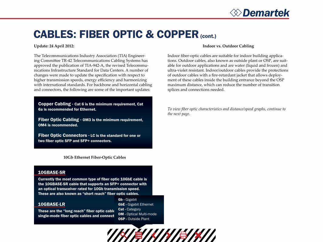
Copper Cabling - Cat 6 is the minimum requirement, Cat 6a is recommended for Ethernet.
Fiber Optic Cabling - OM3 is the minimum requirement, OM4 is recommended.
Fiber Optic Connectors - LC is the standard for one or two fiber optic SFP and SFP+ connectors.
Currently the most common type of fiber optic 10GbE cable is the 10GBASE-SR cable that supports an SFP+ connector with an optical transceiver rated for 10Gb transmission speed. These are also known as “short reach” fiber optic cables.
10GBASE-SR
These are the “long reach” fiber optic cables that support single-mode fiber optic cables and connectors.
10GBASE-LR
Update: 24 April 2012:
The Telecommunications Industry Association (TIA) Engineer-ing Committee TR-42 Telecommunications Cabling Systems has approved the publication of TIA-942-A, the revised Telecommu-nications Infrastructure Standard for Data Centers. A number of changes were made to update the specification with respect to higher transmission speeds, energy efficiency and harmonizing with international standards. For backbone and horizontal cabling and connectors, the following are some of the important updates:
10Gb Ethernet Fiber-Optic Cables
Indoor vs. Outdoor Cabling
Indoor fiber-optic cables are suitable for indoor building applica-tions. Outdoor cables, also known as outside plant or OSP, are suit-able for outdoor applications and are water (liquid and frozen) and ultra-violet resistant. Indoor/outdoor cables provide the protections of outdoor cables with a fire-retardant jacket that allows deploy-ment of these cables inside the building entrance beyond the OSP maximum distance, which can reduce the number of transition splices and connections needed.
To view fiber optic characteristics and distance/speed graphs, continue to the next page.
Gb - GigabitGbE - Gigabit EthernetCat - CategoryOM - Optical Multi-modeOSP - Outside Plant

Demartek
CABLES: FIBER OPTIC & COPPER (cont.)
FIBER OPTIC CABLE BY DISTANCE & SPEED
FIBER OPTIC CABLE CHARACTERISTICS
Mode
OM1 OM2 OM3 OM4
Core Diameter Wavelength Modal BandwidthCable Jacket
Color
OM1
1 Gbps
2 Gbps
4 Gbps
8 Gbps
10 Gbps
16 Gbps
OM2
OM3
OS1
OM4
multi-mode
300m
300m
500m
500m
400m
190m
125m
380m
860m
150m
150m
150m
100m
Up to 300m Up to 400m
50m
82m
35m
70m
21m
33m
15m1 1 1 1
200 MHz Orange
Orange
Aqua
Aqua
Yellow
500 MHz
2000 MHz
4700 MHz
62.5 µm
50 µm
50 µm
50 µm
9 µm
multi-mode
850nm1300nm850nm
1300nm850nm
1300nm850nm
1300nm1310nm1550nm
multi-mode
multi-mode
single-mode
OM1 cable is not recommended for 16Gbps FC, but is expected to operate up to 15m
Distances supported in actual configurations are generally less than the distance supported by the raw fiber optic cable. The distances shown here are for 850 nm wavelength multi-mode cables. The 1300 nm wavelength multi-mode cables can support longer distances.
1
µm - MicrometerMHz - Megahertznm - nanometerm - meterOM - Optical Multi-modeGbps - Gigabits per second FC - Fibre Channel
///
///
///
Demartek
CABLES: FIBER OPTIC & COPPER (cont.)
Active Copper vs. Passive Copper
Passive copper connections are common with many interfaces. The industry is finding that as the transfer rates increase, passive copper does not provide the distance needed and takes up too much physi-cal space. The industry is moving towards an active copper type of interface for higher speed connections, such as 6Gbps SAS. Ac-tive copper connections include components that boost the signal, reduce the noise and work with smaller-gauge cables, improving signal distance, cable flexibility and airflow. These active copper components are expected to be less expensive and consume less electric power than the equivalent components used with fiber optic cables.
Copper: 10GBASE-T and 1000BASE-T
1000BASE-T cabling is commonly used for 1Gb Ethernet traffic in general, and 1Gb iSCSI for storage connections. This is the familiar four pair copper cable with the RJ45 connectors. Cables used for 1000BASE-T are known as Cat5e (Category 5 enhanced) or Cat6 (Category 6) cables.
10BASE-T cabling supports 10Gb Ethernet traffic, including 10Gb iSCSI storage traffic. The cables and connectors are similar to, but not the same as the cables used for 1000BASE-T. 10GBASE-T cables are Cat6a (Category 6 augmented), also known as Class EA cables. These support the higher frequencies required for 10Gb transmission up to 100 meters (330 feet). Cables must be certified for 10GBASE-T compliance, and is typically deployed in Europe. Cat6 cables may work in 10GBASE-T deployments up to 55m, but should be tested first. 10GBASE-T cabling is not expected to be de-ployed for FCoE applications in the near future. Some newer 10GbE switches support 10GBASE-T (RJ45) connectors.
10GBASE-CR - Currently, the most common type of copper 10GbE cable is the 10GBASE-CR cable that uses an attached SFP+ connec-tor, also known as a Direct Attach Copper (DAC). This fits into the same for factor connector and housing as the fiber optic cables with SFP+ connectors. Many 10GbE switches accept cables with SFP+ connectors, which support both copper and fiber optic cables. These cables are available in 1m, 3m, 5m, 7m, 8.5m, and longer distances. The most commonly deployed distances are 3m and 5m.
10GBASE-CX4 - These cables are older and not very common. This type of cable and connector is similar to cables used for InfiniBand technology.
Continue reading for information on connector types.
iSCSI - Internet Small ComputerSystems InterfaceSAS - Serial Attached SCSIFC - Fiber ChannelGbE - Gigabit EthernetGbps - Gigabits per second SFP+ - Small Form-Factor Pluggable m - Meter
iSCSI - Internet Small ComputerSystems InterfaceSAS - Serial Attached SCSIFC - Fiber ChannelGbE - Gigabit EthernetGbps - Gigabits per second SFP+ - Small Form-Factor Pluggable m - Meter
Demartek
CONNECTOR TYPES
SFP+ QSFP+ CONNECTOR/INTERFACE
Several types of connectors are available with cables used for stor-age interfaces. This is not an exhaustive list but is intended to show the more common types. Each of the connector types includes the number of lanes (or channels) and the rated speed.
As of early 2011, the fastest generally available connector speeds supported were 10Gbps per lane. Significantly higher speeds are currently achieved by bundling multiple lanes in parallel, such as 4x10 (40Gbps), 10x10 (100Gbps), 12x10 (120Gbps), etc. Most of the current implementations of 40GbE and 100GbE use multiple lanes of 10GbE and are considered “channel bonded” solutions.
14Gbps per lane connectors appeared in the last half of 2011. These connectors support 16Gb Fibre Channel (single-lane) and 56Gb (FDR) InfiniBand (multi-lane).
25Gbps per lane connectors may become available in 2012 or 2013 as prototypes. When 25Gbps per lane connectors are available, then higher speeds, such as 100Gbps can be achieved by bundling four of these lanes together. Other variations of bundling multiple lanes of 25Gbps may be possible, such as 10x25 (250Gbps), 12x25 (300Gbps) or 16x25 (400Gbps). It is expected that the 25Gbps (actu-ally 28 Gbps) connectors will support 32Gb Fibre Channel in single-lane configurations and higher speeds for Ethernet and InfiniBand in multi-lane configurations.
In calendar Q1 2012, several fiber-optic connector manufacturers demonstrated working prototypes of the “25/28G” connectors. These connectors support speeds up to 28Gbps per lane and will be used for 100Gbps Ethernet (100GbE) in a 4x25 configuration. These connector technologies will also be used for other high-speed ap-plications such as the next higher speeds of Fibre Channel (32GFC) and InfiniBand. End-user products with these higher speed tech-nologies were originally estimated to become available in 2013 or 2014, but more work remains before 25Gb products become gener-ally available.
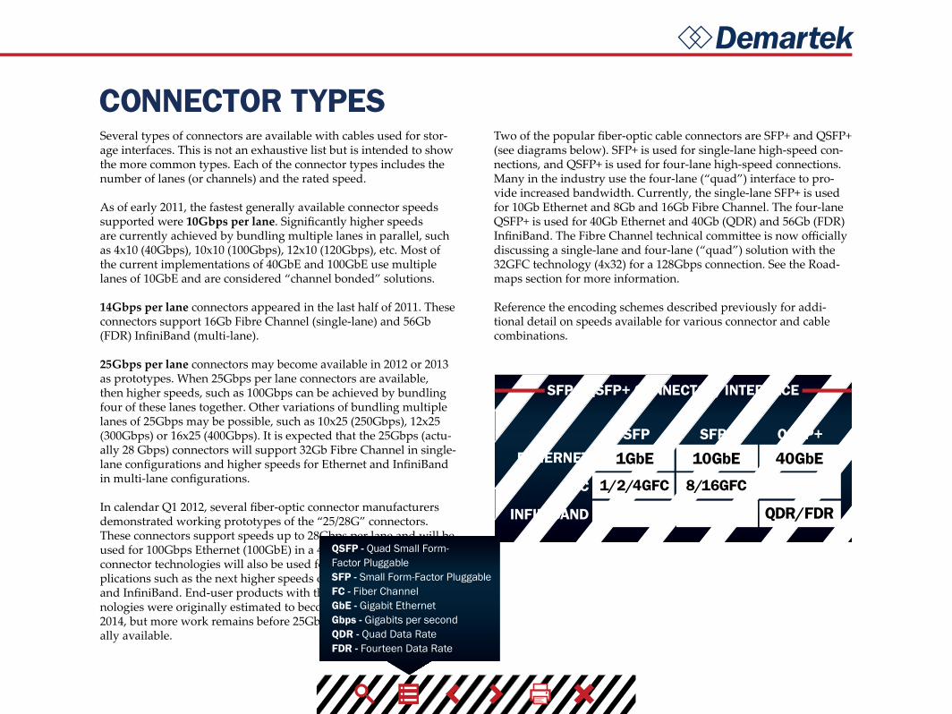
Two of the popular fiber-optic cable connectors are SFP+ and QSFP+ (see diagrams below). SFP+ is used for single-lane high-speed con-nections, and QSFP+ is used for four-lane high-speed connections. Many in the industry use the four-lane (“quad”) interface to pro-vide increased bandwidth. Currently, the single-lane SFP+ is used for 10Gb Ethernet and 8Gb and 16Gb Fibre Channel. The four-lane QSFP+ is used for 40Gb Ethernet and 40Gb (QDR) and 56Gb (FDR) InfiniBand. The Fibre Channel technical committee is now officially discussing a single-lane and four-lane (“quad”) solution with the 32GFC technology (4x32) for a 128Gbps connection. See the Road-maps section for more information.
Reference the encoding schemes described previously for addi-tional detail on speeds available for various connector and cable combinations.
SFP SFP+ QSFP+ETHERNET
FC
INFINIBAND
1GbE 10GbE 40GbE
QDR/FDR
1/2/4GFC 8/16GFC
QSFP - Quad Small Form-Factor PluggableSFP - Small Form-Factor PluggableFC - Fiber ChannelGbE - Gigabit EthernetGbps - Gigabits per second QDR - Quad Data Rate FDR - Fourteen Data Rate

Demartek
CONNECTOR TABLE
MINI SAS
CXP
CFP
MINI SAS HD
COPPER CX4
SMALL FORM-FACTOR PLUGGABLE
SMALL FORM-FACTOR PLUGGABLE ENHANCED
QUAD SMALL FORM-FACTOR PLUGGABLE
QUAD SMALL FORM-FACTOR PLUGGABLE
ENHANCED
TYPE LANESMAX. SPEED
PER LANE(Gbps)
MAX. SPEEDTOTAL (Gbps) CABLE TYPE USAGE
SAS 4
4
16
16
10
10
5
6 24 Copper 3Gb, 6Gb SAS
Various
6Gb, 12Gb SAS
10Gb Ethernet,SDR & DDRInfiniBand
10Gb Ethernet,8 & 16Gb FC, 10Gb FCoE
40Gb Ethernet,DDR, QDR & FDR
InfiniBand,64Gb FC
1Gb Ethernet,FC: 1, 2, 4Gb
100Gb Ethernet,120Gb other
100Gb Ethernet
Copper
Copper
Copper
Copper,Optical
Copper,Optical
Copper,Optical
Copper,Optical
Optical
20
20
64
16
4
48, 96
100, 120
100
5
12
4
1
1
4
4
10, 12
10
4, 8SAS
CX4
SFP
SFP+
QSFP
QSFP+
CXP
CFP
QSFP - Quad Small Form-Factor PluggableSFP - Small Form-Factor PluggableFC - Fibre ChannelFCoE - Fibre Channel over EthernetSAS - Serial Attached SCSIGb - GigabitGbE - Gigabit EthernetGbps - Gigabits per second SDR - Single Data RateDDR - Double Data RateQDR - Quad Data Rate FDR - Fourteen Data Rate
Demartek
CONNECTOR DIAGRAMS
Mini SAS Copper CX4 SFP/SFP+ QSFP/QSFP+Mini SAS HD
Click the connector above to view diagrams
source: Molexsource: Molexsource: Molexsource: Molexsource: Molex
QSFP - Quad Small Form-Factor PluggableSFP - Small Form-Factor PluggableSAS - Serial Attached SCSI
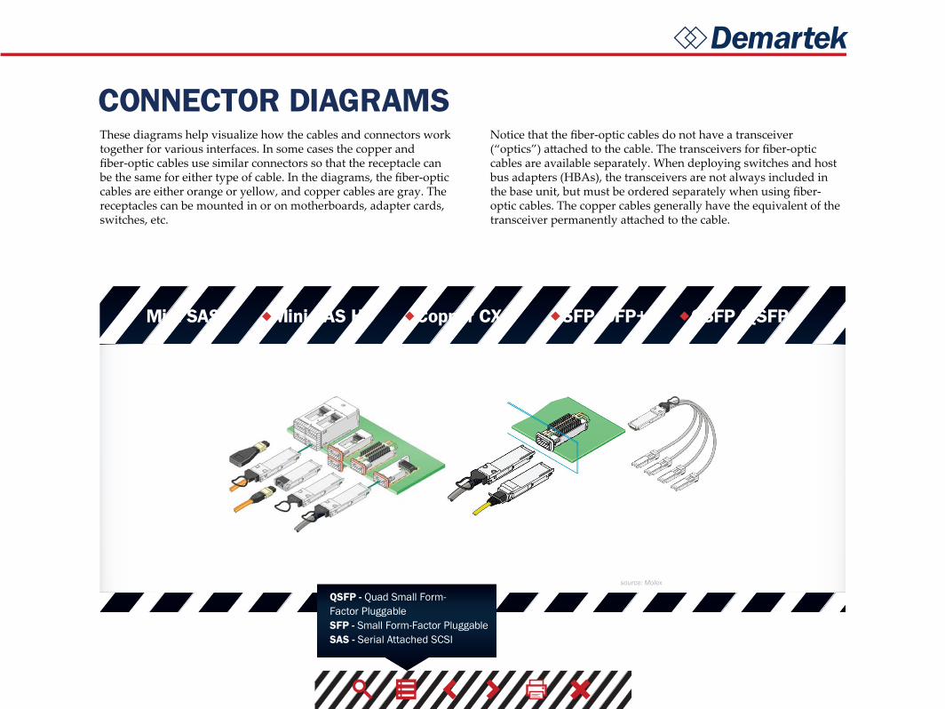
These diagrams help visualize how the cables and connectors work together for various interfaces. In some cases the copper and fiber-optic cables use similar connectors so that the receptacle can be the same for either type of cable. In the diagrams, the fiber-optic cables are either orange or yellow, and copper cables are gray. The receptacles can be mounted in or on motherboards, adapter cards, switches, etc.
Notice that the fiber-optic cables do not have a transceiver (“optics”) attached to the cable. The transceivers for fiber-optic cables are available separately. When deploying switches and host bus adapters (HBAs), the transceivers are not always included in the base unit, but must be ordered separately when using fiber-optic cables. The copper cables generally have the equivalent of the transceiver permanently attached to the cable.

Demartek
CONNECTOR TYPES (cont.)Mini SFP
In the second half of 2010, a new variant of the SFP/SFP+ connector was introduced to accommodate the Fibre Channel backbone with 64-port blades and the planned increased density Ethernet core switches. This new connector, known as mSFP, mini-SFP or mini-LC SFP, narrows the optical centerline of a conventional SFP/SFP+ connector from 6.25 mm to 5.25 mm. Although this connector looks very much like a standard SFP style connector, it is narrower and is required for the higher-density devices. The photo provided here shows the difference between mini-SFP and the standard size.
CXP and CFP
The CXP (copper) and CFP (optical) connectors are expected to be used initially for switch-to-switch connections. These are expected for Ethernet and may also be used for InfiniBand. CFP connectors currently support 10 lanes of 10 Gbps connections (10x10) that consume approximately 35-40 watts. CFP2 is a single board, smaller version of CFP that also supports 10x10 but uses less power than CFP. During 2013, quite a bit of development activity is focused on CFP2. A future CFP4 connector is in the planning stages that is expected to use the 25/28G connectors and support 4x25. CFP4 is expected to handle long range fiber optic distances.
Mini SAS and Mini SAS HD
The Mini SAS connector is the familiar 4-lane connector available on most SAS cables today. The Mini SAS HD connector provides twice the density as the Mini SAS connector, and is available in 4-lane and 8-lane configurations. The Mini SAS HD connector is the same connector for passive copper, active copper and optical SAS cables. The diagrams below compare these two types of SAS connectors.
SFP - Small Form-Factor PluggableSAS - Serial Attached SCSI

Demartek
PCI EXPRESS (PCIe)
PCIe DATA RATES
PCI Express, also known as PCIe, stands for Peripheral Component Interconnect Express and is the computer industry standard for the I/O bus for computers introduced in the last few years. The first ver-sion of the PCIe specification, 1.0a, was introduced in 2003. Version 2.0 was introduced in 2007 and version 3.0 was introduced in 2010. These versions are often identified by their generation (“gen 1,” “gen 2,” etc.). It can take a year or two between the time the speci-fication is introduced and general availability of computer systems and devices using those specification versions. The PCIe specifica-tions are developed and maintained by the PCI-SIG (PCI Special Interest Group). PCI Express and PCIe are registered trademarks of the PCI-SIG.
Data rates for different versions of PCIe are shown in the table below. PCIe data rates are expressed in Gigatransfers per second (GT/s) and are a function of the number of lanes in the connection. The number of lanes is expressed with an “x” before the number of lanes, and is often spoken as “by 1,” “by 4,” etc. PCIe supports full-duplex (traffic in both directions). The data rates shown below are in each direction. Note the explanation of encoding schemes previously described.
Efforts are underway to enable SATA and SAS to be carried over PCIe connections. See the roadmaps section above.
GT/s
PCIe 1.x
PCIe 2.x
PCIe 3.x
Encoding x1 x2 x4 x8 x16
2.5 250MBps
500MBps
500MBps
1GBps
1GBps
1GBps
2GBps
2GBps
2GBps
4GBps
4GBps
4GBps
8GBps
8GBps
16GBps
5
8
8b/10b
8b/10b
128b/130bGBps - Gigabytes per secondMBps - Megabytes per secondGT/s - Gigatransfers per secondI/O - Input/OutputSATA - Serial ATASAS - Serial Attached SCSI

Demartek
PCI EXPRESS (PCIe) (cont.)Mini-PCIe - PCI Express cards are also available in a mini PCIe form factor. This is a special form factor for PCIe that is approxi-mately 30mm x 51mm or 30mm x 26.5mm, designed for laptop and notebook computers, and equivalent to a single-lane (x1) PCIe slot. A variety of devices including WiFi modules, WAN modules, video/audio decoders, SSDs and other devices are available in this form factor.
SFF-8639 - SFF-8639 is the I/O backplane connector designed for high-density SSD storage devices and is backward compatible with existing storage interfaces. SFF-8639 supports PCIe/NVMe, SAS and SATA devices and enables hot plug and hot swap of devices while the system is running. Revision 0.7 of the SFF-8639 specification was released in March 2014, with Revision 1.0 expected by year-end 2014. The SFF-8639 connector is expected to meet similar electrical requirements as a standard PCIe CEM connector.
M-PCIe™ - M-PCIe is the specification that maps PCIe over the MIPI ® Alliance M-PHY® technology used in low-power mobile and handheld devices. M-PCIe is optimized for RFI/EMI require-ments and supports M-PHY gears 1, 2 and 3 and will be extended to support gear 4.
M.2 - M.2 is the next generation PCIe connector for ultra-thin tablets and other mobile platforms. It’s multiple socket definitions support WWAN, SSD and other applications. M.2 can support PCIe protocols or SATA protocol, but not both at the same time on the same device. M.2 supports a variety of board width and length options. M.2 is available in single-sided modules that can be soldered down, or single-single-sided and dual-sided modules used with a connector.
PCIe 2.0 - Servers that have PCIe 2.0 x8 slots can support two ports of 10GbE or two ports of 16GFC on one adapter.
PCIe 3.0 - On 6 March 2012, the major server vendors announced their next generation servers that support PCIe 3.0, which, among other things, doubles the I/O throughput rate from the previous generation. These servers also provide up to 40 PCIe 3.0 lanes per processor socket, which is also at least double from the previous server generation. Workstation and desktop computer mother-boards that support PCIe 3.0 first appeared in late 2011. PCIe 3.0 graphics cards appeared in late 2011. Other types of adapters sup-porting PCIe 3.0 were announced in 2012 and 2013. The PCIe3.0 specification was completed in November 2010.
PCIe 3.1 - The PCIe 3.1 specification was released in October 2014. It incorporates M-PCIe and consolidates numerous protocol exten-sions and functionality for ease of access.
PCIe 4.0 - In November 2011, the PCI-SIG announced the approval of 16 gigatransfers per second as the bit rate for the next generation of PCIe architecture, known as PCIe 4.0. After technical analysis, it was determined that 16 GT/s can be manufactured and deployed with known technologies, while maintaining backward compat-ibility with previous generations of PCIe architecture such as PCIe 1.x, 2.x and 3.x. Revision 0.5 of the PCIe 4.0 specification is expected by year-end 2014, while Revision 0.9 is expected to be available in 1H 2016. It may take up to a year or more for products that support PCIe4.0 technology to become generally available after the final PCIe 4.0 specification is complete.
OCuLINK - OCuLINK is intended to be a low-cost, small cable form factor for PCIe internal and external devices, offering bit rates starting at 8Gbps, with headroom to scale, and new independent cable lock integration. OCuLINK supports x1, x2, and x4 lanes of PCIe 3.0 connectivity. OCuLINK supports passive cables capable of reaching up to 3 meters and active copper and optical cables.
PCI-SIG - PCI Special Interest GroupNVMe - Non Volatile Memory ExpressSSD - Solid State DriveCEM - Card ElectroMechanicalsI/O - Input/OutputGT/s - Gigatransfers per second GbE - Gigabit EthernetGFC - Gigabit Fibre Channel
Demartek
PCI EXPRESS (PCIe) (cont.)
Active copper cables can reach up to 10 meters while active optical cables can reach up to 300 meters in length. The OCuLINK specifi-cation will be completed in the first calendar quarter of 2015 with products expected shortly thereafter.
I/O Virtualization - In 2008, the PCI-SIG announced the completion of its I/O Virtualization (IOV) suite of specifications including sin-gle-root IOV (SR-IOV) and multi-root IOV (MR-IOV). These tech-nologies can work with system virtualization technologies and can allow multiple operating systems to natively share PCIe devices.SR-IOV is currently supported with several 10GbE NICs and hyper-visors. See the recent Demartek I/O Virtualization presentation for additional detail.
The concept of sharing PCIe devices or providing access to PCIe devices that may be physically larger than some smaller form-factor systems can accommodate has led to the development of external connections to some PCIe devices. Cables have been developed for extending the PCIe bus outside of the chassis holding the PCIe slots. These cables are specified by indicating the number of PCIe lanes (x4, x8, etc.) supported. Cables are typically available for x4, x8 and x16 lane configurations. Common cable lengths are 1m and 3m.
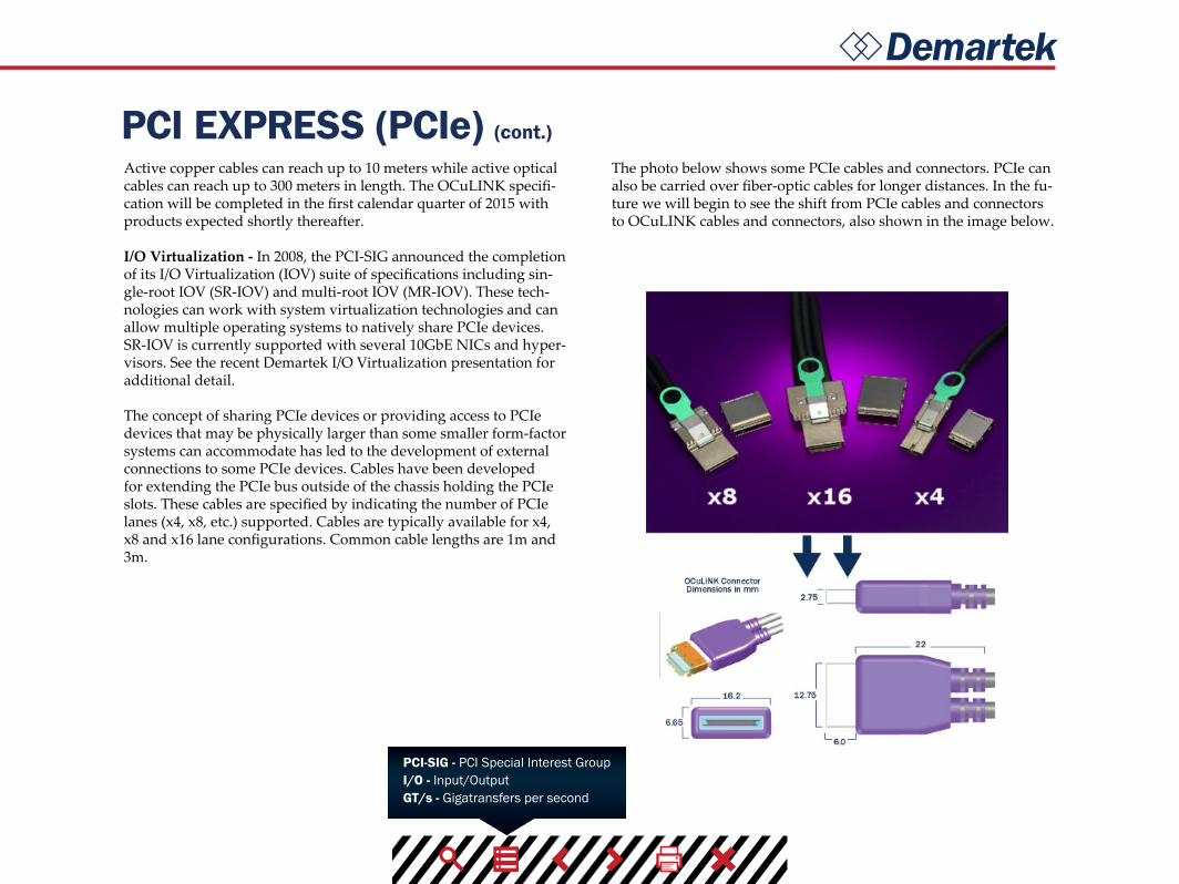
The photo below shows some PCIe cables and connectors. PCIe can also be carried over fiber-optic cables for longer distances. In the fu-ture we will begin to see the shift from PCIe cables and connectors to OCuLINK cables and connectors, also shown in the image below.
PCI-SIG - PCI Special Interest GroupI/O - Input/OutputGT/s - Gigatransfers per second