stop - inter-lux.com · 16 118 ft (36 m) 14 150 ft (46 m) 12 200 ft (61 m) *actual distance must be...
TRANSCRIPT
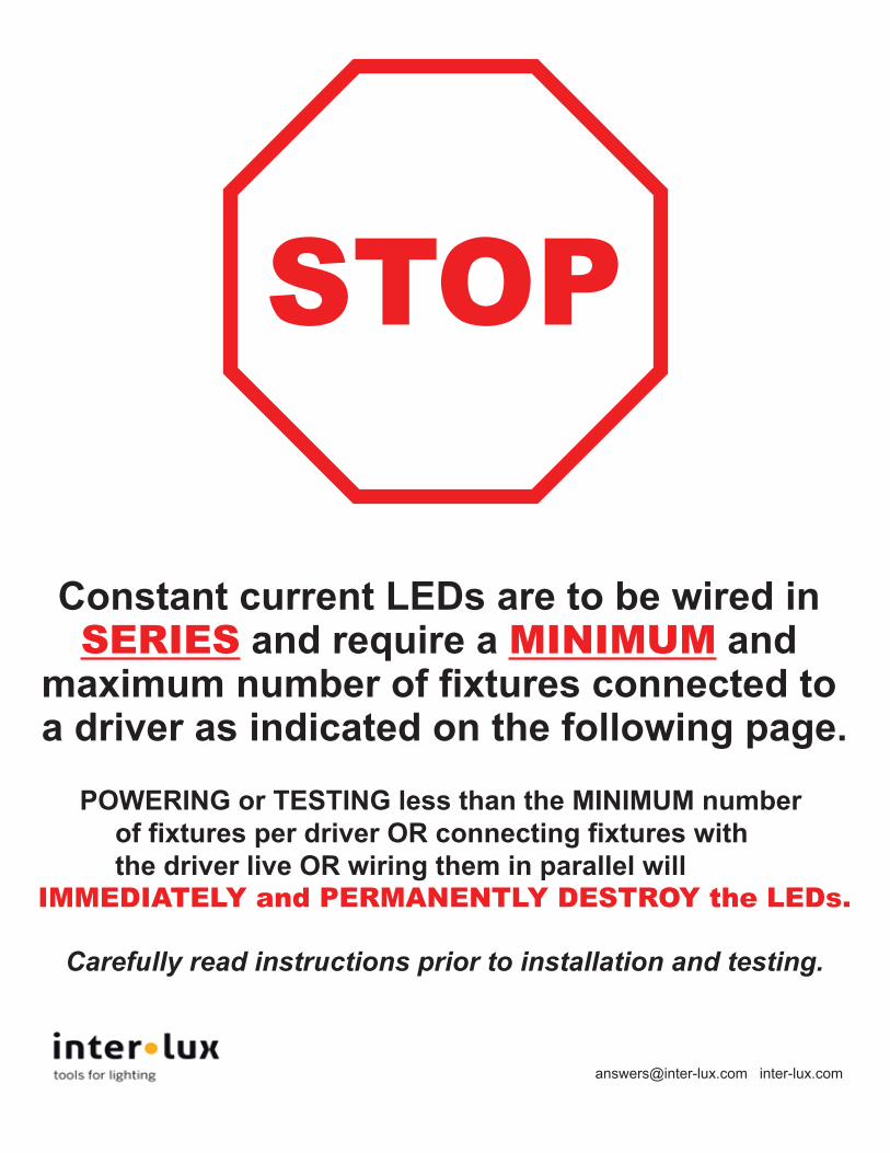
Constant current LEDs are to be wired in SERIES and require a MINIMUM and
maximum number of fixtures connected to a driver as indicated on the following page.
POWERING or TESTING less than the MINIMUM number of fixtures per driver OR connecting fixtures with the driver live OR wiring them in parallel will
IMMEDIATELY and PERMANENTLY DESTROY the LEDs.
Carefully read instructions prior to installation and testing.
[email protected] inter-lux.com
STOP
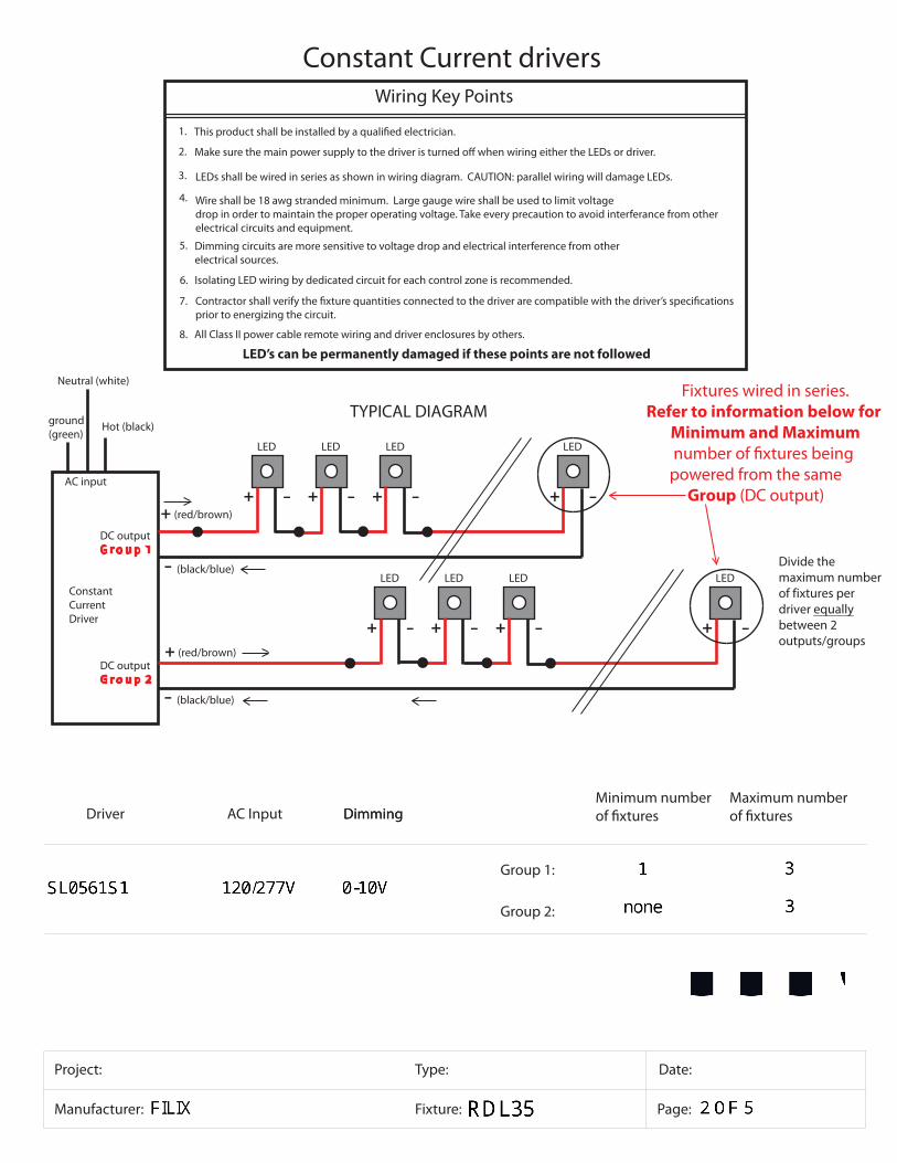
Wire shall be 18 awg stranded minimum. Large gauge wire shall be used to limit voltagedrop in order to maintain the proper operating voltage. Take every precaution to avoid interferance from other electrical circuits and equipment.
LEDs shall be wired in series as shown in wiring diagram. CAUTION: parallel wiring will damage LEDs.
Wiring Key Points
Dimming circuits are more sensitive to voltage drop and electrical interference from otherelectrical sources.
Isolating LED wiring by dedicated circuit for each control zone is recommended.
1.
6.
5.
4.
3.
2.
LED’s can be permanently damaged if these points are not followed
Fixtures wired in series.Refer to information below for
Minimum and Maximum
Dimming
powered from the same Group (DC output)
Project: Type:
Manufacturer: Fixture:
Date:
Page:
Driver DimmingMinimum number Maximum number
AC Input
Constant Current drivers
7.prior to energizing the circuit.
All Class II power cable remote wiring and driver enclosures by others.8.
Constant CurrentDriver
Hot (black)
Neutral (white)
AC input
ground(green)
+ -
LED
+ -
LED
+ -
LED
+ -
LED
+ (red/brown)
+ -
LED
+ -
LED
+ -
LED
+ -
LED
-
+ (red/brown)
(black/blue)
DC outputG r o u p 2
- (black/blue)
DC outputG r o u p 1
Group 1:
Group 2:
TYPICAL DIAGRAM
Divide the maximum number of fixtures per driver equally between 2 outputs/groups
2.0”
3.5”4.5”
9.0”
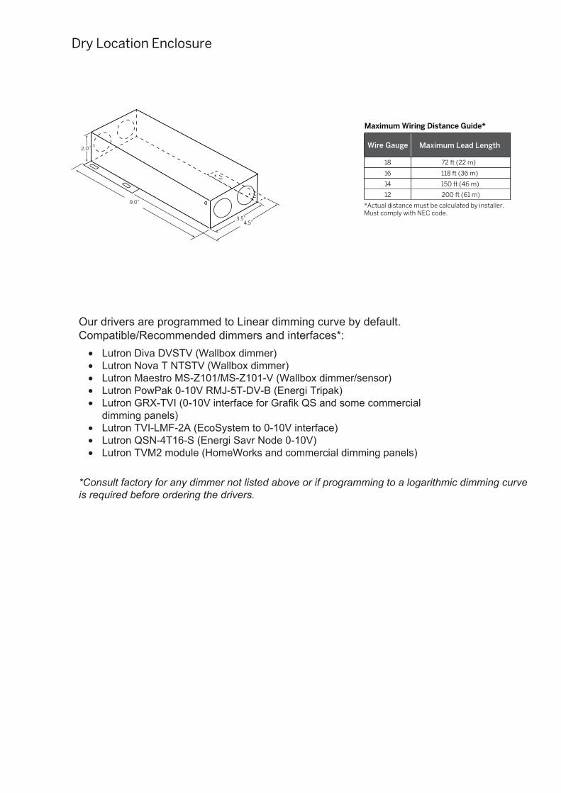
Wire Gauge Maximum Lead Length
18 72 ft (22 m)
16 118 ft (36 m)
14 150 ft (46 m)
12 200 ft (61 m)
*Actual distance must be calculated by installer. Must comply with NEC code.
Our drivers are programmed to Linear dimming curve by default. Compatible/Recommended dimmers and interfaces*:
• Lutron Diva DVSTV (Wallbox dimmer)• Lutron Nova T NTSTV (Wallbox dimmer)• Lutron Maestro MS-Z101/MS-Z101-V (Wallbox dimmer/sensor)• Lutron PowPak 0-10V RMJ-5T-DV-B (Energi Tripak)• Lutron GRX-TVI (0-10V interface for Grafik QS and some commercial
dimming panels)• Lutron TVI-LMF-2A (EcoSystem to 0-10V interface)• Lutron QSN-4T16-S (Energi Savr Node 0-10V)• Lutron TVM2 module (HomeWorks and commercial dimming panels)
*Consult factory for any dimmer not listed above or if programming to a logarithmic dimming curveis required before ordering the drivers.
Dry Location Enclosure
Maximum Wiring Distance Guide*
© 2012 eldoLED. All rights reserved. V3.4 More product documentation and eldoLED’s terms and conditions are available at www.eldoled.com.
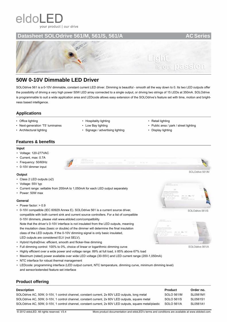
Datasheet SOLOdrive 561/M, 561/S, 561/A AC Series
50W 0-10V Dimmable LED DriverSOLOdrive 561 is a 0-10V dimmable, constant current LED driver. Dimming is beautiful - smooth all the way down to 0. Its two LED outputs offer
the possibility of driving a very high power 50W LED array connected to a single output, or driving two strings of 15 LEDs at 350mA. SOLOdrive
is programmable to suit a wide application area and LEDcode allows easy extension of the SOLOdrive’s feature set with time, motion and bright-
ness based intelligence.
Applications
• Office lighting
• Next-generation ‘T5’ luminaires
• Architectural lighting
• Hospitality lighting
• Low Bay lighting
• Signage / advertising lighting
• Retail lighting
• Public area / park / street lighting
• Display lighting
Features & benefits
Input
• Voltage: 120-277VAC
• Current, max: 0.7A
• Frequency: 50/60Hz
• 0-10V dimmer input
Output
• Class 2 LED outputs (x2)
• Voltage: 55V typ
• Current range: settable from 200mA to 1,050mA for each LED output separately
• Power: 50W max
General
• Power factor: > 0.9
• 0-10V compatible (IEC 60929 Annex E). SOLOdrive 561 is a current source driver,
compatible with both current sink and current source controllers. For a list of compatible
0-10V dimmers, please visit www.eldoled.com/compatibility
Note that the driver’s 0-10V interface is not insulated from the LED outputs, meaning
the insulation class (basic or double) of the dimmer will determine the final insulation
class of the LED outputs. If the 0-10V dimming signal is only basic insulated,
LED outputs are considered ELV (not SELV).
• Hybrid HydraDrive: efficient, smooth and flicker-free dimming
• Full dimming control: 100% to 0%, choice of linear or logarithmic dimming curve
• Highly efficient over a wide power and voltage range: 89% at full load, ≥ 85% above 67% load
• Maximum (rated) power available over wide LED voltage (30-55V) and LED current range (200-1,050mA)
• NTC interface for robust thermal management
• LEDcode: programming interface (LED output current, NTC temperature, dimming curve, minimum dimming level)
and sensor/extended feature set interface
Product offering
Description Product Order no.
SOLOdrive AC, 50W, 0-10V, 1 control channel, constant current, 2x 60V LED outputs, long metal SOLO 561/M SL0561M1
SOLOdrive AC, 50W, 0-10V, 1 control channel, constant current, 2x 60V LED outputs, square metal SOLO 561/S SL0561S1
SOLOdrive AC, 50W, 0-10V, 1 control channel, constant current, 2x 60V LED outputs, square metal/plastic SOLO 561/A SL0561A1
© 2012 eldoLED. All rights reserved. V3.4 More product documentation and eldoLED’s terms and conditions are available at www.eldoled.com.
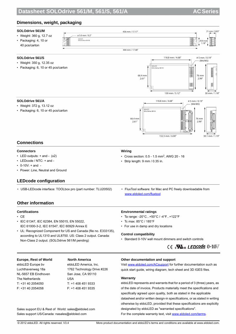
444 mm / 17.48”
29.9 mm1.18”
21 mm / 0.83”436 mm / 17.17”
ø 5.0 mm / 0.2”
SOLOLdrive 561/M
76 mm2.99”
66.4 mm2.61”
130 mm / 5.12”
118.8 mm / 4.68”
30 mm / 1.18”
ø 5 mm / 0.19”(M4/M5)
76 mm2.99”
66.4 mm2.61”
152.5 mm / 6.00”
118.8 mm / 4.68”
30.1 mm / 1.19”
ø 5 mm / 0.19”(M4/M5)
SOLOdrive 561/A
Datasheet SOLOdrive 561/M, 561/S, 561/A AC Series
Dimensions, weight, packaging
SOLOdrive 561/M
• Weight: 360 g, 12.7 oz
• Packaging: 4, 10 or
40 pcs/carton
SOLOdrive 561/S
• Weight: 350 g, 12.35 oz
• Packaging: 6, 10 or 45 pcs/carton
SOLOdrive 561/A
• Weight: 372 g, 13.12 oz
• Packaging: 6, 10 or 45 pcs/carton
Connections
Connectors
• LED outputs: + and - (x2)
• LEDcode / NTC: + and -
• 0-10V: + and -
• Power: Line, Neutral and Ground
Wiring
• Cross section: 0.5 - 1.5 mm2, AWG 20 - 16
• Strip length: 9 mm / 0.35 in.
LEDcode configuration
• USB-LEDcode interface: TOOLbox pro (part number: TLU20502) • FluxTool software: for Mac and PC freely downloadable from
www.eldoled.com/fluxtool
Other information
Certifications
• CE
• IEC 61347, IEC 62384, EN 55015, EN 55022,
IEC 61000-3-2, IEC 61547, IEC 60929 Annex E
• UL: Recognized Component for US and Canada (file no. E333135),
according to UL1310 and UL8750. US: Class 2 output. Canada:
Non-Class 2 output. (SOLOdrive 561/M pending)
Environmental ratings
• Ta range: -20°C...+50°C / -4°F...+122°F
• Tc max: 85°C / 185°F
• For use in damp and dry locations
Control compatibility
• Standard 0-10V wall mount dimmers and switch controls
Europe, Rest of World North America
eldoLED Europe bv eldoLED America, Inc.
Luchthavenweg 18a 1762 Technology Drive #226
NL-5657 EB Eindhoven San Jose, CA 95110
The Netherlands USA
T: +31 40 2054050 T: +1 408 451 9333
F: +31 40 2054058 F: +1 408 451 9335
Sales support EU & Rest of World: [email protected]
Sales support US/Canada: [email protected]
Other documentation and support
Visit www.eldoled.com/ACsupport for further documentation such as
quick start guide, wiring diagram, tech sheet and 3D IGES files.
Warranty
eldoLED represents and warrants that for a period of 3 (three) years, as
of the date of invoice, Products materially meet the specifications and
specifically agreed upon quality, both as stated in the applicable
datasheet and/or written design-in specifications, or as stated in writing
otherwise by eldoLED, provided that these specifications are explicitly
designated by eldoLED as "warranted specifications".
For the complete warranty text, visit www.eldoled.com/terms.
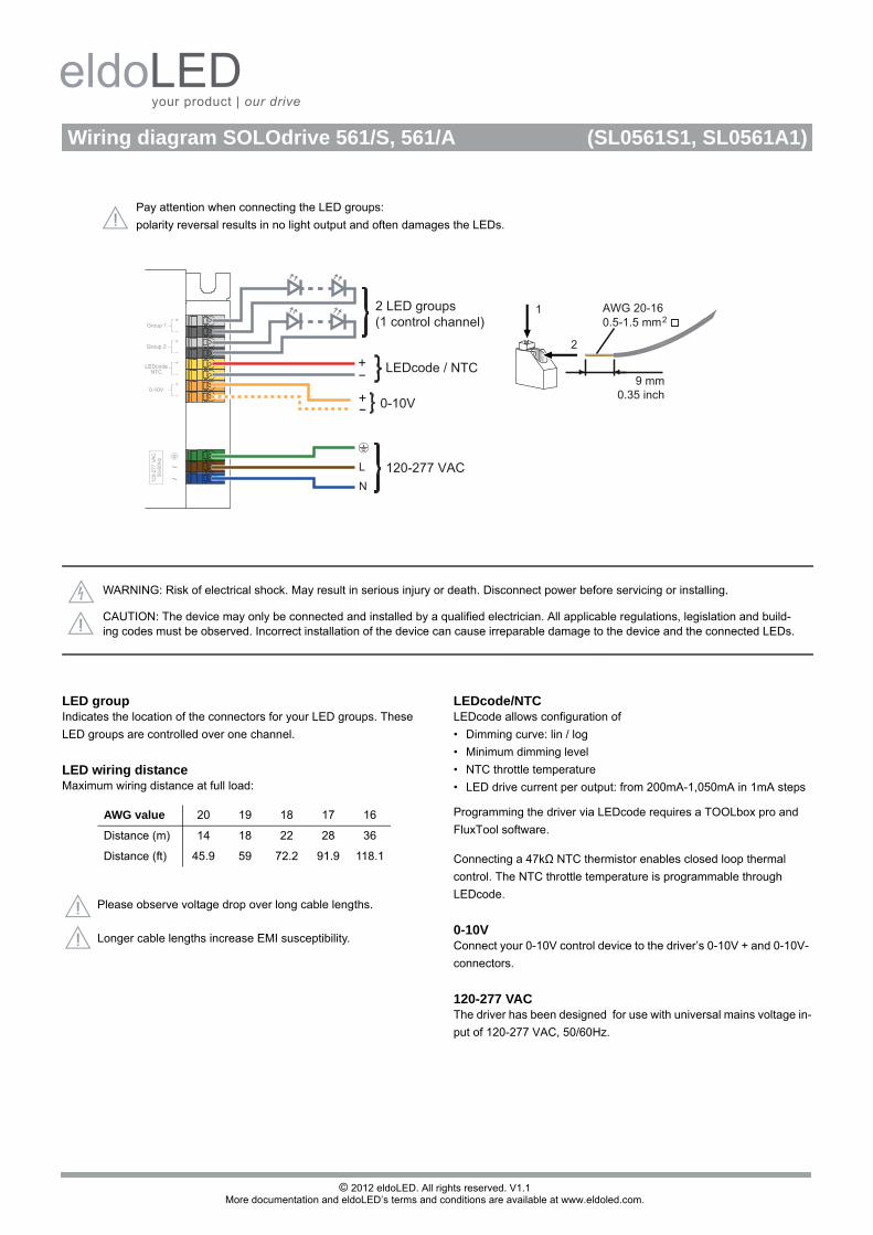
Pay attention when connecting the LED groups:
polarity reversal results in no light output and often damages the LEDs.
© 2012 eldoLED. All rights reserved. V1.1More documentation and eldoLED’s terms and conditions are available at www.eldoled.com.
120-277 VAC
2
1
9 mm0.35 inch
0.5-1.5 mm2AWG 20-16
0-10V+-
L
N
+- LEDcode / NTC
2 LED groups(1 control channel)
Wiring diagram SOLOdrive 561/S, 561/A (SL0561S1, SL0561A1)
WARNING: Risk of electrical shock. May result in serious injury or death. Disconnect power before servicing or installing.
CAUTION: The device may only be connected and installed by a qualified electrician. All applicable regulations, legislation and build-ing codes must be observed. Incorrect installation of the device can cause irreparable damage to the device and the connected LEDs.
LED groupIndicates the location of the connectors for your LED groups. These
LED groups are controlled over one channel.
LED wiring distanceMaximum wiring distance at full load:
LEDcode/NTCLEDcode allows configuration of
• Dimming curve: lin / log
• Minimum dimming level
• NTC throttle temperature
• LED drive current per output: from 200mA-1,050mA in 1mA steps
Programming the driver via LEDcode requires a TOOLbox pro and
FluxTool software.
Connecting a 47kΩ NTC thermistor enables closed loop thermal
control. The NTC throttle temperature is programmable through
LEDcode.
0-10VConnect your 0-10V control device to the driver’s 0-10V + and 0-10V-
connectors.
120-277 VACThe driver has been designed for use with universal mains voltage in-
put of 120-277 VAC, 50/60Hz.
AWG value 20 19 18 17 16
Distance (m) 14 18 22 28 36
Distance (ft) 45.9 59 72.2 91.9 118.1
Please observe voltage drop over long cable lengths.
Longer cable lengths increase EMI susceptibility.