stock suppliers of steel decking profiles guidance notes€¦ · slab (basis of design in...
TRANSCRIPT

stockyards limitedStock Suppliers of Steel Decking Profiles
Guidance Notes

Guidance NotesDesignGeneralSMD’s metal decking products are commonly used as part of a composite floor slab, where the decking acts as both permanent formwork and tensile reinforcement (sagging) in the bottom of the slab (basis of design in accordance with BS5950: Parts 4 & 6 or Eurocodes 3 and 4).
Alternatively, our decking profiles may be used as permanent formwork only. In this situation any reinforcement required to support the specified imposed loads is to be designed by the project structural engineer, ignoring any contribution from the metal decking.
All our profiles use steel strip in compliance with BS EN 10143 & BS EN 10346 with guaranteed minimum yield strengths of 350 and 450 N/mm2 and a minimum coating mass of 275g/m2.
Construction StageAt Construction Stage the decking is designed to support the weight of the wet concrete, reinforcement and an allowance for temporary construction load in accordance with BS5950 Part 4 or Eurocode 1. Where this load is likely to be exceeded, SMD Technical Department should be consulted.
The best practice guidance for concrete placement outlined in this manual should be adopted to avoid overloading of the decking.
Where necessary to position materials directly on to the metal decking for short periods, the following recommendations should be followed:
a. Any load applied to the metal decking during its temporary construction stage should be restricted to 1.5kN/m2. Special attention is required regarding this load if the decking requires propping during construction. Temporary propping must be in place before any construction traffic is allowed over the deck.
b. Materials should always be positioned directly over a supporting steel member.
c. Materials should be positioned in a workmanlike manner.
d. Materials should be placed onto timbers or pallets etc. to spread any load. These should be positioned directly over supporting steel members.
e. Timbers or pallets should be positioned with the main support running at right angles to the ribs of the decking.
NOTE: Metal decking is not designed to accommodate the storage of materials during its construction stage, therefore until the structural concrete topping is placed, any such storage undertaken is to be carried out with due regard to the above notes.
Deflection (Construction Stage)Metal decking is designed to deflect under the weight of wet concrete as it is placed, in accordance with BS5950 Parts 4 & 6 or Eurocodes 3 and 4. The decking is designed for the slab thickness
specified, based on constant thickness. No allowance is made for any additional loading due to excessive concrete thickness as a consequence of deflection of the structural steel frame during construction. This must be considered by the designer when specifying the slab surface tolerance required, to avoid experiencing deflections far greater than that designed.
The best practice guidance for concreting outlined in this manual (and more comprehensively given in The Concrete Society – Good Concrete Guide 5: Composite concrete slabs on steel decking) should be followed to avoid excessive deflection. Refer page 07 – Design Table Notes for further information on deflection limits.
Temporary ProppingDecking is usually designed un-propped, however for longer or single span locations (i.e. temporary crane void infills) temporary propping may be required during construction to support the wet weight of the concrete and any construction imposed loads. When supplied, SMD decking layout drawings will indicate all areas where temporary propping is required with a chain-dotted line and the notation 'TP'. If in doubt ASK.
Should a project require tighter control of decking deflection at construction stage, the structural engineer may specify temporary propping to spans within the limits of the un-propped tables provided in this document.
Where temporary props are required to spans exceeding 4.0m for R51 and TR60+ and 5.0m for TR80+ (and at any unsupported or large edges – Refer Fig 1.0), the propping arrangement is to be in position, levelled and adequately braced prior to installation of the decking. Consideration should be given to the method of fall arrest used in this situation.
Temporary Propped Edge Trim Detail Fig 1.0
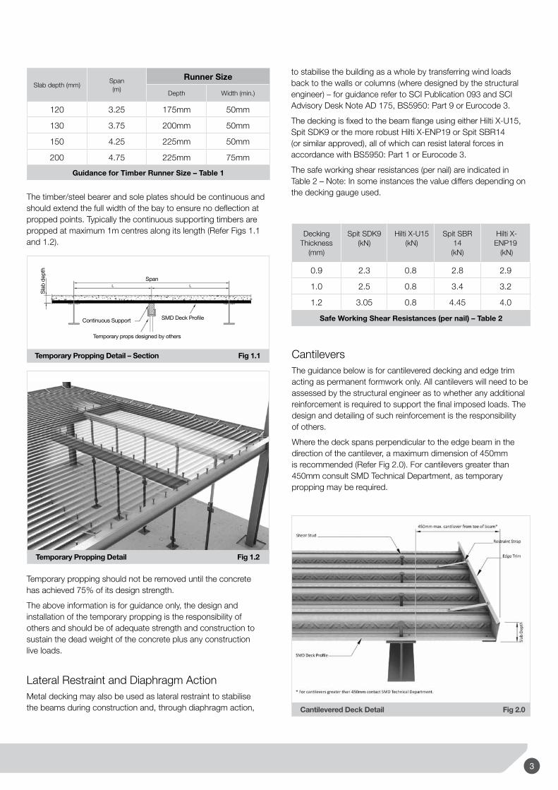
Props normally consist of a length of timber and/or steel plate supported by adjustable steel props. The minimum bearing length of the timber and/or plate depends upon the thickness of the slab, these are typically in the range of 75-100mm (Refer Table 1 on page 20).
2
Cantilevered Deck Detail Fig 2.0
The timber/steel bearer and sole plates should be continuous and should extend the full width of the bay to ensure no deflection at propped points. Typically the continuous supporting timbers are propped at maximum 1m centres along its length (Refer Figs 1.1 and 1.2).
Decking Thickness
(mm)
Spit SDK9(kN)
Hilti X-U15 (kN)
Spit SBR 14
(kN)
Hilti X-ENP19 (kN)
0.9 2.3 0.8 2.8 2.9
1.0 2.5 0.8 3.4 3.2
1.2 3.05 0.8 4.45 4.0
Safe Working Shear Resistances (per nail) – Table 2
Temporary Propping Detail – Section Fig 1.1
Sla
b de
pth
Span
SMD Deck ProfileContinuous Support
Temporary props designed by others
L L
Temporary Propping Detail Fig 1.2
Slab depth (mm)Span(m)
Runner Size
Depth Width (min.)
120 3.25 175mm 50mm
130 3.75 200mm 50mm
150 4.25 225mm 50mm
200 4.75 225mm 75mm
Guidance for Timber Runner Size – Table 1
to stabilise the building as a whole by transferring wind loads back to the walls or columns (where designed by the structural engineer) – for guidance refer to SCI Publication 093 and SCI Advisory Desk Note AD 175, BS5950: Part 9 or Eurocode 3.
The decking is fixed to the beam flange using either Hilti X-U15, Spit SDK9 or the more robust Hilti X-ENP19 or Spit SBR14 (or similar approved), all of which can resist lateral forces in accordance with BS5950: Part 1 or Eurocode 3.
The safe working shear resistances (per nail) are indicated in Table 2 – Note: In some instances the value differs depending on the decking gauge used.
Temporary propping should not be removed until the concrete has achieved 75% of its design strength.
The above information is for guidance only, the design and installation of the temporary propping is the responsibility of others and should be of adequate strength and construction to sustain the dead weight of the concrete plus any construction live loads.
Lateral Restraint and Diaphragm ActionMetal decking may also be used as lateral restraint to stabilise the beams during construction and, through diaphragm action,
CantileversThe guidance below is for cantilevered decking and edge trim acting as permanent formwork only. All cantilevers will need to be assessed by the structural engineer as to whether any additional reinforcement is required to support the final imposed loads. The design and detailing of such reinforcement is the responsibility of others.
Where the deck spans perpendicular to the edge beam in the direction of the cantilever, a maximum dimension of 450mm is recommended (Refer Fig 2.0). For cantilevers greater than 450mm consult SMD Technical Department, as temporary propping may be required.
3
Guidance Notes
Overall Slab
Depth
Edge Trim
Dimension from toe of Beam
1.0mm 1.2mm 1.6mm 2.0mm
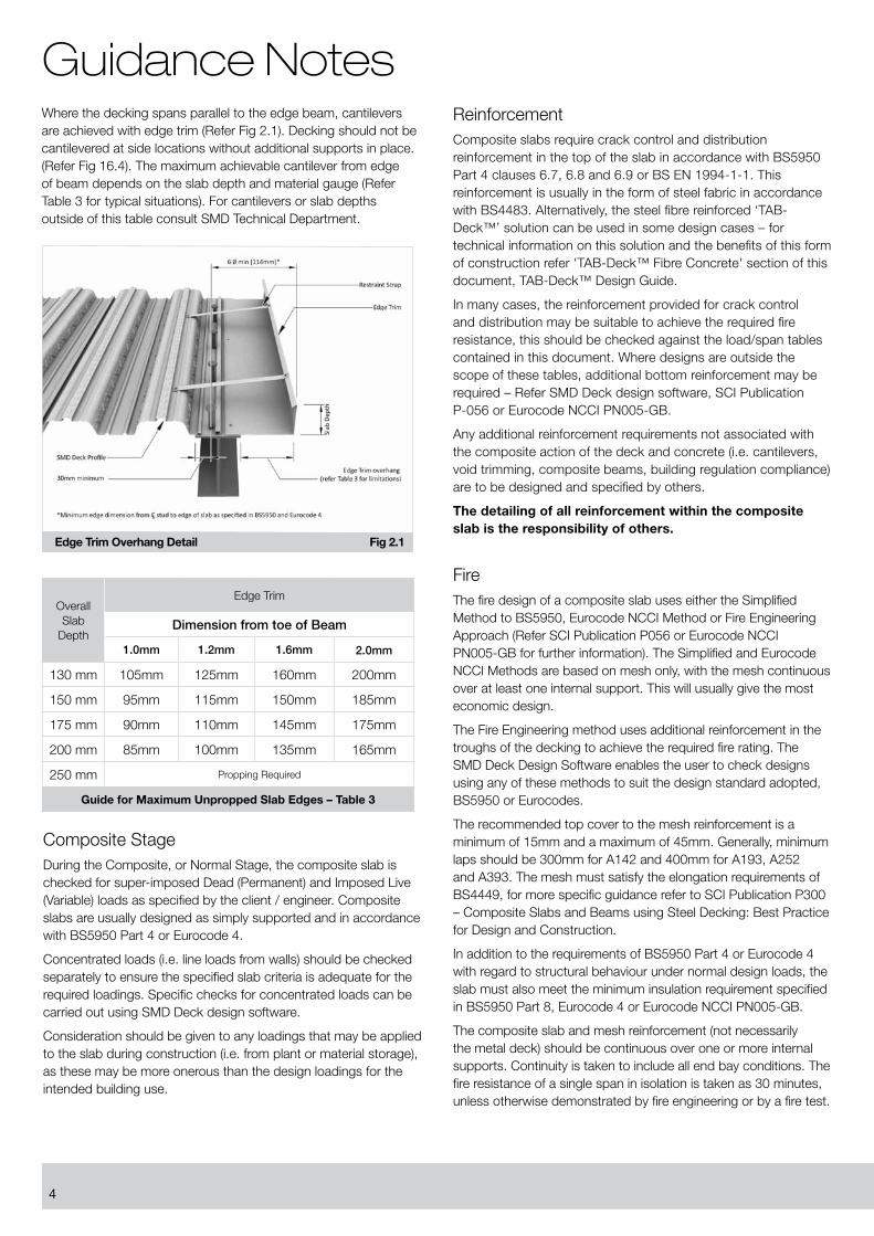
130 mm 105mm 125mm 160mm 200mm
150 mm 95mm 115mm 150mm 185mm
175 mm 90mm 110mm 145mm 175mm
200 mm 85mm 100mm 135mm 165mm
250 mm Propping Required
Guide for Maximum Unpropped Slab Edges – Table 3
Where the decking spans parallel to the edge beam, cantilevers are achieved with edge trim (Refer Fig 2.1). Decking should not be cantilevered at side locations without additional supports in place. (Refer Fig 16.4). The maximum achievable cantilever from edge of beam depends on the slab depth and material gauge (Refer Table 3 for typical situations). For cantilevers or slab depths outside of this table consult SMD Technical Department.
ReinforcementComposite slabs require crack control and distribution reinforcement in the top of the slab in accordance with BS5950 Part 4 clauses 6.7, 6.8 and 6.9 or BS EN 1994-1-1. This reinforcement is usually in the form of steel fabric in accordance with BS4483. Alternatively, the steel fibre reinforced ‘TAB-Deck™’ solution can be used in some design cases – for technical information on this solution and the benefits of this form of construction refer 'TAB-Deck™ Fibre Concrete' section of this document, TAB-Deck™ Design Guide.
In many cases, the reinforcement provided for crack control and distribution may be suitable to achieve the required fire resistance, this should be checked against the load/span tables contained in this document. Where designs are outside the scope of these tables, additional bottom reinforcement may be required – Refer SMD Deck design software, SCI Publication P-056 or Eurocode NCCI PN005-GB.
Any additional reinforcement requirements not associated with the composite action of the deck and concrete (i.e. cantilevers, void trimming, composite beams, building regulation compliance) are to be designed and specified by others.
The detailing of all reinforcement within the composite slab is the responsibility of others.
FireThe fire design of a composite slab uses either the Simplified Method to BS5950, Eurocode NCCI Method or Fire Engineering Approach (Refer SCI Publication P056 or Eurocode NCCI PN005-GB for further information). The Simplified and Eurocode NCCI Methods are based on mesh only, with the mesh continuous over at least one internal support. This will usually give the most economic design.
The Fire Engineering method uses additional reinforcement in the troughs of the decking to achieve the required fire rating. The SMD Deck Design Software enables the user to check designs using any of these methods to suit the design standard adopted, BS5950 or Eurocodes.
The recommended top cover to the mesh reinforcement is a minimum of 15mm and a maximum of 45mm. Generally, minimum laps should be 300mm for A142 and 400mm for A193, A252 and A393. The mesh must satisfy the elongation requirements of BS4449, for more specific guidance refer to SCI Publication P300 – Composite Slabs and Beams using Steel Decking: Best Practice for Design and Construction.
In addition to the requirements of BS5950 Part 4 or Eurocode 4 with regard to structural behaviour under normal design loads, the slab must also meet the minimum insulation requirement specified in BS5950 Part 8, Eurocode 4 or Eurocode NCCI PN005-GB.
The composite slab and mesh reinforcement (not necessarily the metal deck) should be continuous over one or more internal supports. Continuity is taken to include all end bay conditions. The fire resistance of a single span in isolation is taken as 30 minutes, unless otherwise demonstrated by fire engineering or by a fire test.
Edge Trim Overhang Detail Fig 2.1
Composite StageDuring the Composite, or Normal Stage, the composite slab is checked for super-imposed Dead (Permanent) and Imposed Live (Variable) loads as specified by the client / engineer. Composite slabs are usually designed as simply supported and in accordance with BS5950 Part 4 or Eurocode 4.
Concentrated loads (i.e. line loads from walls) should be checked separately to ensure the specified slab criteria is adequate for the required loadings. Specific checks for concentrated loads can be carried out using SMD Deck design software.
Consideration should be given to any loadings that may be applied to the slab during construction (i.e. from plant or material storage), as these may be more onerous than the design loadings for the intended building use.
4

SupplyDelivery and AccessDecking and edge trim are delivered on 25 tonne capacity articulated vehicles with trailers up to 13.50m long. On supply and fix contracts, SMD's site manager will contact the client to arrange deliveries allowing seven days notice. Where site access restrictions apply, deliveries can be arranged on alternative vehicles (i.e. 10 tonne rigid or hi-ab).
Upon arrival at site, the driver will allow a maximum 2 hour off-loading period – unless agreed otherwise with the SMD contracts team. It is normal for the offloading to be undertaken by the steelwork contractor in conjunction with the erection of the steel frame. SMD do not undertake any offloading of delivery vehicles.
Maximum Pack Size for R51
24 No Sheets with a max weight of approx. 2.5 tonnes
Maximum Pack Size for TR60+
18 No sheets with a max weight of approx. 2.5 tonnes
Maximum Pack Size for TR80+
15 No Sheets with a max weight of approx. 2.5 tonnes
Sheet lengths are determined on the SMD layout drawing to suit the requirements of the building footprint. Normally they will be designed to give the most effective use of the decking, reducing any propping requirements and with Health & Safety for unloading and installation in mind. Where possible, sheet lengths are restricted to 7.5m for R51, 8.0m for TR60+ and 10.0m for TR80+ due to manual handling restrictions.
Pack Labels and LocationsDecking bundles are identified on SMD’s layout drawings and will have a unique identification tag (Refer Fig 3.0 showing a typical pack label with all relevant information). The packs are also marked with a spray stripe down one side to indicate how they should be loaded onto the steel frame. The spray line should face in the direction of the setting out point as indicated on the relevant SMD drawing.
For site control, the colour of the spray line on the pack differs to indicate the decking gauge:
Green – 0.9mm gauge Blue – 1.0mm gauge Red – 1.2mm gauge
The loading out positions for decking packs are clearly detailed on SMD decking layout drawings. It is essential that all packs are loaded out in the correct position and orientation to avoid any H&S issues and to minimise manual handling required.
VibrationThe recommended minimum natural frequency of a composite slab is 5Hz when used in office or domestic type applications. This limit may need to be increased in areas such as gyms, dance studios or plant areas supporting machinery, where rhythmic loading is expected. For further guidance refer SCI Publications P076: Design guide on the vibration of floors and P354: Design of floors for vibration – A New Approach.
DurabilityAll SMD decks are manufactured from galvanised steel coil to BS EN 10346 with a standard 275g/m2 coating. The design life to first maintenance that can be expected for different environments is:
Internal, Dry & Unpolluted: 20 – 50 years (Typical for most common applications – offices, warehouses, hospitals, airports)
Suburban & Rural: 5 – 10 years
Coastal: 2 – 5 years
Industrial and Urban: 2 – 5 years
Should greater periods be required, additional site applied protection to the underside of the profile may be required. Refer SMD Technical Department for further guidance.
Composite Beam DesignComposite beams with steel decking should be designed in accordance with BS5950 Part 3: Section 3.1 or Eurocode 4. Thru' deck welded shear studs are commonly used to transfer horizontal shear forces between the steel beam and concrete slab, as required in the relevant design standard. These studs are welded to the supporting beams through the troughs in the decking, therefore it is essential that the decking and beam geometries are considered by the structural engineer when specifying stud quantities on beams running perpendicular to the decking span (Refer pages 27-28 for limitations).
The resistance of shear studs in solid concrete is outlined in BS5950 Part 3: Section 3.1 and Eurocode 4. When used in composite decked slabs, these stud resistances may need to be reduced due to the decking geometry and/or orientation. For calculation of shear stud reduction factors, refer to BS5950 Part 3: Section 3.1 or Eurocode 4.
Transverse reinforcement is required in the concrete flange of composite beams to resist splitting forces. This will usually be in the form of mesh and/or additional bars running perpendicular to the beam centre line. In locations where the decking spans perpendicular to the beam centre line, the deck can also be considered, providing it is either continuous across the beam flange or securely anchored to the beam flange with thru' deck welded studs at butt joints. Where perimeter beams are designed as composite, additional 'U' bars may be required depending on edge dimensions, refer SCI Publication P300: Composite slabs and beams using steel decking: Best practice for design and construction.
5

Guidance Notes
SMD Pack Labels Fig 3.0
stockyards limitedStock Suppliers of Steel Decking Profiles
Offloading, Hoisting and StorageDuring offloading and hoisting, care should be taken to avoid damage to the decking sheets caused by excessive pressure from slings or chains. Decking bundles should NEVER be dropped (in any way) from delivery vehicles.
It is normal for the packs to be loaded directly from the delivery vehicle onto the steel frame. Whilst loading packs onto the steel frame consideration should be given to pack positions to avoid overloading.
When necessary to store decking packs at ground level for prolonged periods of time, the packs should be sat on timber bearers to avoid direct contact with the ground.
InstallationSMD ServiceSMD provide a highly professional installation service. All operatives are fully trained and competent, with directly employed installation teams based throughout the UK.
Where decking is supplied on a 'Supply Only' basis it is the clients responsibility to ensure the works are executed in a safe manner. Any person/s contracted to either install or work in the proximity of decking should be made aware of the guidance and recommendations contained in this Technical Manual.
Method of InstallationSMD products should only be installed by those competent and trained to do so. Specific reference should also be given to the BCSA Code of Practice for Metal Decking and Stud Welding, but as a minimum the following procedure should be followed.
• Pre Start: Prior to commencement of deck installation, a system of fall protection and safe access must be in place.
• Weather conditions: Decking bundles should not be opened if all the sheets in the bundle cannot be fixed or left in a safe condition at the end of the shift. Consideration must be given during periods of bad weather and any unfixed sheets should be secured at the end of each day by using a temporary strap secured to the frame or decking.
• Supporting structure: Refer to Fixings section (page 24) for guidance on minimum bearings.
• Access to Level: Wherever possible the decking installation should be planned to commence from the corner of a building or phase, so that the number of leading edges are limited.
• Laying decking sheets: Using the access provided, the installer should straddle the first bundle of decking to remove the banding. The first decking sheet will then be pushed out onto the steelwork to be used as a working platform from which to lay the remaining sheets in that bay. Decking sheets should then be lapped together, lined up and fixed into place once the adjacent bay has been laid and the troughs of the decking have been lined through.
• Cutting / Notching: Decking sheets are detailed to be delivered to site at the correct square cut length. Where decking ribs sit over beams that are to receive welded shear studs, around columns and other protrusions, notching is required. This should be carried out by trained operatives using petrol driven disc cutters with appropriate blade or plasma cutters.
• Decking fixings: Fixing of the deck and edge trim to the supporting steelwork will be carried out using low velocity powder actuated cartridge tools ('shot firing') or in certain circumstances using self tapping screws. Refer to Fixings section (page 24) for fixing type and spacing centres.
• Side Laps: The side laps of decking sheets are stitched together using self tapping screws, installed with 110v screw guns, provided to side laps at maximum 1.00m centres.
• Sealing and finishing off: Gaps up to 5mm are acceptable as they are not sufficient to allow concrete aggregate to escape. Note: The decking is not intended to provide a watertight finish and a degree of fines and water seepage can be expected from the panel ends and joints.
• Edge trims: Generally supplied in 3.00m standard lengths, each length should be fixed at the perimeter and straps fixed at centres as indicated in Edge Trim & Flashings section (page 25) with self-tapping screws.
6

• Forming holes and openings: Where trimming steels are provided, the decking sheets may be cut to suit the size of the opening and edge trim installed. Where there is no supporting steelwork the voids will need to be decked over. The opening should then be formed by the concreting contractor who will box out the opening prior to pouring the concrete. For further information refer to page 30 of this manual or SCI Publication P300.
It is the Steelwork Contractors responsibility to ensure the supporting structure is in a stable condition and adequately restrained prior to proceeding with the decking installation. Any additional support plates or angles required around columns, penetrations or splices should also be provided by the Steelwork Contractor – For advice on locations where additional support may be required, contact SMD Technical Department.
FixingsThe minimum bearing requirements for the decking are 50mm on steelwork (this is increased to 60mm where sheets are to receive thru' deck welded shear studs) and 70mm on masonry or concrete.
Recommended fixing types as follows:
• Wherebeamsaretoreceivethru'deckweldedshearstudsHiltiX-U 15 (DAK) or Spit SDK9 shot-fired nails or similar approved
• Wherenoshearstudsarespecified,HiltiX-ENP19orSpitSBR14 shot-fired nails or similar approved
• FixingstomasonryshouldbeDrill&HammerAnchors,SpitP370 or P560, or similar approved. Hilti X-SW or Spit CR9 shot-fired nails or similar approved (Refer Fig 4.1)
• Whereshot-firedfixingsarenotpermitted,self-drillingscrewsFixfast DF12 5.5 x 38, Hilti S-MD55Z 5.5 x 40 or similar approved, can be used. Beam flanges will require pre-drilling where thickness exceeds 12mm.
• Atsidestitchingofsheetsand/orrestraintstrappingofedgetrim, Hilti S-MD01Z 4.8 x 19 , Fixfast DF3 HEX 4.8 x 20 or similar approved.
Decking must be fixed at 300mm centres at each end and at 600mm centres over intermediate supports, or closest multiples to suit trough centres (for TR60+ 333mm and 666mm respectively).
Side stitching for R51, TR60+ and TR80+ deck is to be provided at maximum 1.0m centres from mid-span using self-tapping screws.
Where decking is required to provide lateral restraint and no thru' deck welded shear studs are specified, the fixing type should be checked by the engineer. (Refer to BS5950: Part 3 or Eurocode 4 and Table 2 on page 20).
CoverWidth
Support
Support
Support
Supp
ort
Supp
ort
R51
TR60+
TR80+
A B C D
Spacings
Mid-span
A
A
B
C
B
D D
1000
1000
1000
300
333
300
600
666
600
750
750
750
EndcapsProduct
1000
mm
cen
tres
(2)
(3)
(2) (1)
(2)
(1)
B D Straps
Spacings
Edge trim <200mm high 750 750 750Edge trim 201mm - 300mm 750 750 500
Product
Edge trim 301mm - 450mm 750 750 250*
(No.per sheet width)
A = Side laps of decking sheetsB = End of deck sheetC = Intermediate supportsD = Side stitching
*Two sets of restraint straps are necessary (Refer Fig 16.8).
X
Span
B
A
D
C
A
B
D
A = Stitching at side lapsB = End of deck sheetC = Intermediate supports D = Side supports
Spacings(No. per sheet width)
Product A B C D Endcaps
R51 1000 300 (2) 600 (1) 750 r
TR60+ 1000 333 (3) 666 (2) 750 ✓
TR80+ 1000 300 (2) 600 (1) 750 ✓
Spacings
Product B D Straps
Edge trim <200mm high 750 750 750
Edge trim 201 - 300mm 750 750 500
Edge trim 301 - 450mm 750 750 250*
*Two sets of restraint straps are necessary (Refer Fig 16.8).
Fixing Layout – Quick Reference Fig 4.0
7

Guidance Notes
Decking to Blockwork Perimeter Fixing Detail Fig 4.1
Cartridge ToolsFixing of decking and edge trim is typically carried out using low velocity powder actuated cartridge tools ('shot firing'). This provides a fast and efficient method of securing the decking sheets. The tools used are generally Hilti DX460 or DX76, Spit P370 or P560, or similar approved. All operators must be fully trained, competent to use these tools and at least 18 years of age.
Decking on Shelf Angles (or bottom flanges)Where decking sheets are supported on shelf angles or bottom flanges between beam webs, the shelf angles /bottom flanges should be designed to extend a minimum of 50mm beyond the toe of the beam top flange. This minimum dimension of 50mm is essential to enable the sheets to be physically positioned between toes of top flanges and a cartridge tool to be used to secure the decking into place (Refer Fig 5.0).
Sla
b de
pth
Decking Bearing on Shelf Angles Detail Fig 5.0
SMD Deck Profile Desired position of deck
Example of deck being placedonto shelf angles50 min.
Typical50 min.Typical
Concrete Encased BeamsIn some instances concrete encased perimeter beams may be specified as part of the fire design. It is recommended that the beam is encased to the top flange level off site, therefore enabling the decking to be installed to the beam top flange as normal.
Where it is not possible to carry out the concrete encasement off site, the following procedure is possible using our R51 profile only:
- Decking installed to top flange of perimeter beam as normal.
- The shuttering is then provided by others, this must be designed by the structural engineer to sustain the weight of
the decking, wet concrete and construction imposed loads to avoid the temporary propping requirement indicated in Fig 6.0.
- Decking is then cut back to the line of the shuttering, with temporary propping in place (if required).
- In this detail the decking will not contribute to the shear resistance of the finished slab. Hairpin/tie bar reinforcement in the troughs of the decking profile will need to be designed/ specified by the engineer.
Concrete Encased Beam Detail Fig 6.0
R51 Deck Profile
Temporary propping by others
Reinforcementby others
Timber formworkby others
If propping not in place prior to fixing, decking to bear onto steelbeam & cut back once props are in place
Hairpin tie bar reinforcement – designed and supplied by othersMesh or TAB-DeckTM system
Sla
b de
pth
Decking Around ColumnsDecking around columns is achieved by notching the deck into the web and sealing with tape/foam/flashing to minimise grout loss. Where columns are not framed by incoming beams, angle brackets (provided by the steel contractor) may be required to the relevant column face to support the free end of the decking.
Edge Trim and FlashingsGalvanised edge trim is provided where requested around perimeter and void edges. This edge trim acts as permanent formwork only, to support the wet weight of concrete during construction.
Typically edge trim is supplied to site in lengths of 3.0m where it is then cut to suit. Edge trims are available in varying gauges; 1.0mm, 1.2mm, 1.6mm and 2.0mm. The material gauge is determined by the depth of the concrete slab and the extent of the slab overhang (Refer Table 3 on page 21).
Edge trim can be either fixed to the end of the decking with self tapping screws (Refer Fig 2.0) or to the main supporting structure using similar fixings as used to secure the decking (Refer Fig 2.1).
Edge trim is to be fixed with a bearing of 50mm on steelwork or 70mm on masonry or concrete It should be fixed at both ends and at 750mm centres along its length, with restraint straps fixed to the top edge at 750mm centres, or 500mm centres for slab depths of 200-300mm – (Refer Fig 7.0). For slab depths greater than 300mm consult SMD Technical Department.
8

R51 Slab Edge and Flashings Fig 7.0
Sla
b de
pth
Sla
b de
pth
SMD R51 Deck Profile
SMD R51 Deck Profile
Restraint strap
Restraint strap
SMD flashing (Type 02)utilised when deck sheetfalls short of side bearing beam
Edge trim
Edge trim6 Ø min.(114 min)
30 min.
Where edge trim is required to form a curve, straight lengths are provided to site and the edge trim is faceted on site to form the desired radius (Refer Fig 8.0).
Faceted edge trim detail to form a radius edge Fig 8.0
At perimeter beams and intermediate beams parallel to the deck span (where shear studs are required), should the deck fall short or be positioned such that a trough is not located over the beam flange, galvanised mild steel flashings are provided to form a closure to the profile (Refer Figs 8.1 and 8.2). Flashings are available in 1.2mm, 1.6mm and 2.0mm gauges and are supplied to site in standard 3m lengths. The exact geometry and requirement for these flashings is detailed on SMD decking layout drawings where provided.
Rib flashing detail at perimeter beam Fig 8.1
Edge flashing detail at perimeter beam Fig 8.2
StudweldingGeneralShear studs are manufactured from low carbon steel with a minimum yield strength of 350 N/mm2 and a minimum ultimate tensile strength of 450 N/mm2 in accordance with BS EN ISO 13918. Standard 19mm diameter studs are available to achieve the following length after weld (LAW) 70mm, 95mm, 120mm, 145mm and 170mm. At the present time thru' deck welding of shear studs is restricted to 19mm dia studs or less.
Shear studs are welded through the decking trough onto the beam flange. Where possible, the shear studs should be placed on the centre line of the beam directly over the web to avoid burn through.
For a beam to be studwelded the flange thickness must be a minimum of 0.4 x the stud diameter = 7.6mm for standard 19mm diameter studs.
9

Guidance NotesIn some instances site welding may not be possible (i.e. due to fire hazard or galvanised beams). One alternative is the Hilti HVB shear connector, fixed to the beam with shot-fired fixings using a DX750 or DX76 cartridge tool. The technical properties of the Hilti HVB differ greatly from the standard welded shear stud and therefore, should not be used in place of traditional welded shear studs without approval from the structural engineer. With Hilti HVB shear connectors, for the same degree of shear connection far greater quantities are required when compared to that of welded shear studs.
For further information on Hilti HVB Shear Connectors contact Hilti (UK) on 0800 886 100.
Shear Stud SpacingTo ensure the most effective use of shear studs, the dimensions and configurations shown in Figs 9.0-9.5 should be used (In accordance with BS5950 Part 3 Section 3.1 or BS EN 1994-1-1).
R51 Layout Details – Single Studs Fig 9.0
Note: The minimum flange width is increased for butt joint positions (See Fig 9.1 below)
R51 Layout Details – Staggered Studs @ butt joint Fig 9.1
R51 Layout Details – Studs in pairs Fig 9.2
TR+ Layout Details – Single Studs Fig 9.3
Note: The minimum flange width is increased for butt joint positions (See Fig 9.5)
TR+ Layout Detail – Studs in Pairs Fig 9.4
10

TR+ Layout Detail – Staggered Studs @ Butt Joint Fig 9.5
Unpainted Top FlangesWhere beams are to receive thru' deck welded shear studs, the top flanges are to be free from any type of paint, grease, loose rust or any other coating, as this prevents effective welding and will subsequently reduce the final weld strength. Refer SMD Best Practice Sheet DATA/13 available at www.smdstockyards.co.uk for further information.
Studwelding EquipmentStudwelding is undertaken using purpose built mobile studwelding plant, operating Nelson rectifiers and diesel generators of up to 250 KVa. The plant measuring 7.0m long, 2.5m wide and 4.0m high, requires access to within 6.5m of the steel frame to enable it to be safely earthed. The distance between the generator and the stud welding tool is restricted to a maximum of 80 metres. Where site logistics prevent access to within 6.5m of the frame, additional steel angle (approx. 50mm x 50mm) will be required to achieve earthing.
Static generators approximately 3.0m long, 2.0m wide and 2.0m high, weighing 6 tonnes can also be provided as an alternative. Where a static generator is required, it should be positioned in a well ventilated area and consideration should be given by the Structural Engineer to its location to avoid overloading of the steel frame.
However, in many locations the more preferable option due to its low environmental impact is a 415 volt 3 phase (150 amp per phase) mains supply. Refer SMD Best Practice Sheet DATA/05 available at www.smdstockyards.co.uk for further information.
Length After WeldWhen installing shear studs the length after weld should extend at least 35mm above the top of the main ribs in the decking, therefore the minimum stud height after weld should be 95mm for TR60+ & R51 and 115mm for TR80+. The recommended minimum concrete cover to the top of the stud is 15mm, this should be increased to 20mm if the shear stud is to be protected against corrosion.
TestingAt the start of a new shift a bend test should be carried out on at least the first two shear studs welded, this is to ensure that the welding procedure and current are correct. These studs need to be bent to an angle of 30 degrees from their original axis by placing a pipe over the stud and manually bending the stud in the direction of the span of the beam towards the nearest column. If any failure occurs, the equipment should be reset, replacement studs welded and tests repeated to ensure acceptable quality.
After welding, the ferrules will be broken away from the base of the stud to allow a visual inspection. The broken ferrules will be left on the deck to be absorbed into the concrete and treated as inert aggregate. Bend testing will then be carried out as described above, but to an inclination of 15 degrees (1 in 4). This bend test should be carried out on two studs per beam or 5% (whichever is greater). If a shear stud fails in any location, the studs on either side should also be tested. Any failing studs will need to be replaced.
When testing shear studs reference should be made to the manufacturers instructions, BS5950: Part 3: Section 3.1 or Eurocode 4, BCSA Code of Practice for Metal Decking and Stud Welding and National Structural Steelwork Specification.
Health and SafetyThe design, installation and completion of metal decking projects must be arranged so that the Health & Safety of the operatives undertaking the work, of other trades on site, and of members of the public is ensured.
A number of key factors are paramount in achieving this goal:
Management & SupervisionEnsure supervision is experienced in metal decking and that a suitable qualification such as SMSTS is held. Pre-start visits allow agreement of programme, sequence and co-ordination with other trades. The planning and arrangement of deliveries to allow effective positioning on the steel frame (usually by the erectors) is essential in minimising issues with manual handling. Robust management of the workforce in relation to Safety, Quality and Production ensures safe completion. Handover procedures should be used to ensure works are complete for following trades.
Documentation All companies should have a framework of Policies & Procedures relating to the management of Health & Safety. SMD have developed a specific on site Health & Safety guide to assist operatives with trade specific guidance notes, available to download from www.smdltd.co.uk
Contract specific safety documentation, including Method Statements, Risk Assessments and COSHH data sheets are available for all hazards / activities associated with the handling and fixing of metal decking and associated accessories. The communication of this to the work force, ensures that all operatives understand the risks and preventative measures that have been
11

Guidance Notesagreed. An initial toolbox talk on the method statement, followed by further weekly talks ensures procedures on site are appropriate to the ever changing construction environment. Records of inductions and all toolbox talks should be maintained.
Typical hazards associated with metal decking and associated preventative measures are:
• FallsfromHeight–handrails,safetynets,suitableaccess to level
• HotWorks–exclusionzones,removalofflammablematerials, fire extinguishers
• UseofCartridgeTools–competencyandtraining,PPE
• HandArmVibration–managementprocedures
• Noise–PPE,managementprocedures,suitablework equipment
• CutstoHands–PPE
• ElectricalEquipment–maintenanceand110vtools
• FallingMaterialsfromHeight–trimandtooltethers, loading out procedures
• RemovalofWaste–skips,loadingbaysetc.
• AdverseWeather–managementcontrol
Personal Protective Equipment (PPE)Task Specific PPE will be detailed in Risk Assessments, however the minimum requirements are:
• HardHattoBSEN397
• SafetyBootswithheavydutysteeltoecapandsteelmidsole
• HiVisclothingtoBSEN471Class1
• CutResistantGlovestoBSEN388–ReflexK+ Kevlar Coated
• HearingprotectiontoBSEN352-1
• TintedWeldingGoggles
• EyeProtectiontoBSEN166class1–clearlensesforcutting/ shot firing, smoked lenses for stud welding
Protection of Falls from HeightIn accordance with the Work at Height Regulations 2005 and given that for metal deck installation 'avoid work at height' and 'use work equipment to prevent falls' is not reasonably practicable, all contracts need to adopt a system of work that 'minimises the distance and consequence of a fall'. Methods of fall arrest used are safety netting for steel frame structures and airbags or similar for all other situations. Where safety netting is provided by SMD, this will be undertaken by FASET trained personnel. The contract specific method statement and risk assessment will detail the preferred methods for both fall arrest and installation.
Trained and Competent WorkforceEnsure that all operatives have received manufacturers training in the use of cartridge tools and together with that for abrasive
wheels, stud welding equipment, fire safety training and have achieved the appropriate level of CSCS qualification. Safety netters will be FASET trained and hold IPAF certificates and using MEWPs.
Information and Guidance for Other TradesDON’T land packs on the frame in the incorrect position – It is essential that the decking packs are loaded out in the position indicated on SMD’s decking layout drawings.
DON’T leave any decking sheet unfixed – Unfixed decking sheets pose a danger to others on site, ensure that as areas are being laid that they are not left unattended until fixed. Also at the end of each day, any unfixed sheets in decking packs should be secured down.
DON’T put heavy loads on unprotected deck – Other trades must be made aware of the storage capacity of decking prior to concrete and the appropriate procedures for locating heavy loads on timbers laid on beam lines.
DON’T cut holes/voids in the deck before concreting – If additional holes are required to be cut into the decking before concreting, contact SMD Technical Department for guidance.
DON’T heap concrete or drop from any height – Following concrete trades must be aware of good practice principles when pouring on suspended metal decks, so that overloading is avoided and any propping requirements are in place.
For additional guidance on installation methods and safe working systems, refer to Further Reading section on page 38.
Guidance for Following TradesCleaning the DeckingPrior to the concrete being placed, the decking should be cleared by others of any debris, grease and/or dirt which could adversely affect the bond between the concrete and the decking. Typically, ceramic ferrules left over from the shear studding process can be left distributed over the decking surface and lost within the concrete pour. Final clarification should be sought from the project structural engineer (Refer Concrete Society – Good Concrete Guide 5 for further guidance).
Damaged DeckingCare should be taken when utilising the decking as a working platform, or storing materials for following trades. As any damage resulting from this will require a site inspection and the damaged sheets may require replacement.
12

Forming Service HolesWhen it is necessary to form service holes in a composite slab, following general rules are recommended. For openings at right angles to the deck span:
1. Up to 250mm (for R51) or 300mm (for TR+ profiles): Openings such as these require no special treatment. Prior to placing of concrete the opening is boxed out. When the slab has cured the deck is cut by others, using a non-percussive tool. (Refer Fig 10.0).
Options for Forming Voids Fig 10.0
2. Greater than 250mm (for R51) or 300mm (for TR+ profiles), but less than 700mm: Additional reinforcement is required around the opening, SMD recommend the design be generally in accordance with BS8110 or Eurocode 2. The forming of the hole is as item 1 (Refer Fig 10.0).
Items 1 and 2 relate to holes in isolation and not to a series of holes transverse to the direction of span, which should be considered as one large void. In these cases the metal decking should only be cut after the slab has cured.
3. Greater than 700mm: Structural trimming steelwork designed by others and supplied by the steelwork fabricator, will be required.
These are guidelines only and particular requirements should be checked by the project structural engineer. SMD’s responsibility excludes the design of any additional framing or slab reinforcement for holes or openings.
When forming holes in the decking, consideration needs to be given to Health & Safety. Due consideration should be given to protect against falling through holes. If possible, handrail should be erected around the void. Alternatively, SMD can provide a temporary cover to the opening by decking over the void (unconcreted) for removal by others at a later date. For further guidance regarding service voids, including limitations for positioning and trimming reinforcement design, refer to SCI Publication P300: Composite Slabs and Beams using Steel Decking: Best Practice for Design and Construction.
Construction JointsWith composite floor slabs, it is possible to achieve continuous concrete pours in excess of 1,000m2.
Where construction joints are required, these should always be formed as close as possible to the deck support over which the decking sheets are butt-jointed. The distance from the centre of the end support to the stop end should never exceed one-third of the span between the supports (Refer Fig 11.0).
Construction Joint Detail Fig 11.0
Concrete – ‘The Complete Composite Floor Package’Combining both the composite metal decking and associated concrete topping works as a ‘Complete Composite Floor Package’ can provide significant and tangible benefits.
SMD have an experienced management structure and specialist placing / finishing teams solely responsible for integrating the concrete topping element into the decking package ensuring that these benefits become reality.
Benefits include:
• Economicsolution
• Singlepointresponsibility
• Greaterprogrammecertainty
• Reducedconflictbetweentwosub-contracttrades
• Minimisessiteco-ordination
• Lesscontractadministration
• Competence(concreteundertakenbypeoplewho understand decking)
Associated concrete toppings are co-ordinated in conjunction with the decking and shear stud installation operations, which not only maintains continuity of service for the client but also ensures a quick, seamless process for delivering ‘The Complete Composite Floor Package’.
13

Guidance Notesbe given to this aspect by the Project Team when considering what effects this may have on supplementary trades / finishes (i.e. level to datum specifications are unachievable and therefore subsequent levelling screeds may be necessary to attain such requirements)
Surface FinishThe required concrete finish should relate to the floor finishes being applied so as to provide a key, where required, or compatibility with any curing membranes being applied.
Normally a ‘trowel’ finish is applied to suspended upper floor concrete using a skip float (defined as U1 in 3rd edition of the National Structural Concrete Specification for building construction). Project Teams should note that this type of surface finish will leave fat ridges / trowel marks and occasionally reinforcement ripple visible in the final surface appearance and areas may require some minor remedial attention prior to receiving subsequent floor finishes.
Where a ‘pan’ or ‘power float’ finish is required, this can be provided although it must be specified in the context of the previous deflection section i.e. power floating will make the surface appear smoother and flatter but not level to datum.
Surface RegularityGenerally, the surface regularity achievable for concrete toppings on metal decking is SR3 (+/-10mm under a 2m straight edge as outlined in BS8204-01). In some instances, depending on pour size, concrete volume and only when a full powerfloat finish is carried out, it may be possible to achieve a surface regularity of SR2 (+/-5mm under a 2m straight edge as outlined in BS8204-01). SR1 (+/-3mm under a 2m straight edge as outlined in BS8204-01) is not achievable.
Concrete and ReinforcementConcrete should be specified by the structural engineer so that it is suitable for the intended method of installation (e.g. pumpable) and finishing. Concrete with a minimum consistence class of S3 should be utilised. Mesh fabric and loose bar reinforcement (i.e. ‘U’ bars or straight bars in troughs) should be detailed by the structural engineer and in sufficient time to allow for procurement, delivery and installation. Mesh fabric reinforcement is intended as a method of crack control however, it will not eliminate cracking.
PlacementSMD’s recommendation, which is further explained in MCRMA Technical Paper 13 – Composite Slabs & Beams Using Steel Decking: Best Practice For Design & Construction, is to pour concrete toppings on metal decking to a constant thickness rather than to a datum as this…
• Reducestheriskofoverloadingthedeckandpossiblecollapse
• Eliminatesadditionalcostforoverconsumptionofconcrete
Concrete – Key ConsiderationsTemporary ProppingTemporary propping will be identified on SMD drawings where required. It is the responsibility of the Principal Contractor to obtain a temporary works design approval for any propping that is required and ensure the props are installed prior to concreting. Refer to page 19 for further guidance notes on this subject.
Datum / DeflectionConcrete toppings installed on suspended upper floors cannot be laid to a defined datum due to deck and steel deflections. It is vitally important to understand when installing concrete on metal decking that the supporting structure (both deck and steelwork) will deflect under load during the construction process and this generally occurs for several hours following installation as the structure creeps under the weight of the concrete – Refer to Figs 12.0 and 12.1.
Mid-Bay Slab Deflection Fig 12.0
Section Through Slab Deflection Fig 12.1
Thought must also be given to rolling deflection during the concrete topping installation process. As the pour progresses and the metal decking is loaded in accordance with our recommendations, the decking deflects in the loaded section, which as a consequence alters adjacent decking panels to some degree. It is impossible to then go back into these sections and try and re-level again, as more concrete results in more deflection.
It should be understood that deflection in the structure is beyond the control of a flooring contractor and due consideration should
14
• Enablescommitmenttoachievingarecognisedfinished surface regularity.
The recommended means of pouring concrete onto metal decking is by pumping. Where the concrete is being transferred into position using barrows or by lines of pipe for pumping, boards should be used to provide a load-spreading platform across the deck, thus reducing the risk of accidental damage to the profile.
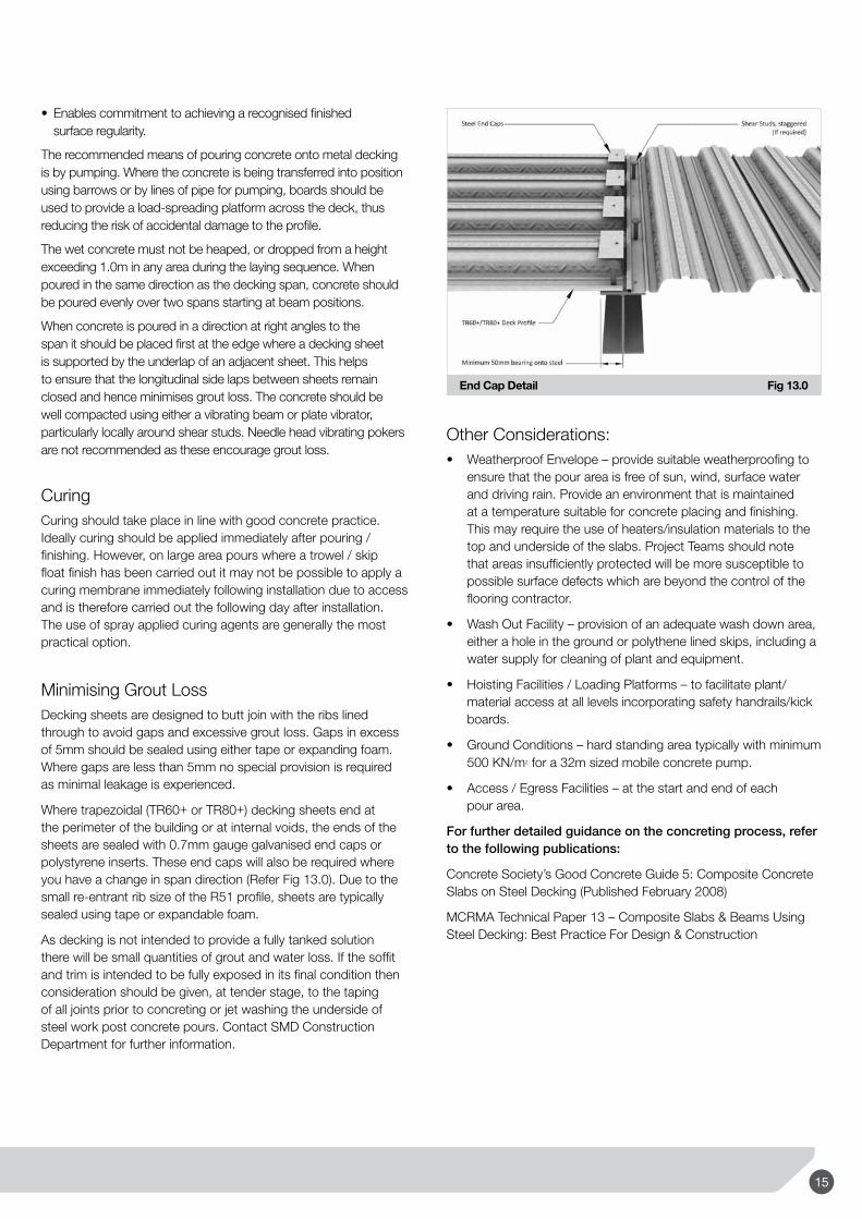
The wet concrete must not be heaped, or dropped from a height exceeding 1.0m in any area during the laying sequence. When poured in the same direction as the decking span, concrete should be poured evenly over two spans starting at beam positions.
When concrete is poured in a direction at right angles to the span it should be placed first at the edge where a decking sheet is supported by the underlap of an adjacent sheet. This helps to ensure that the longitudinal side laps between sheets remain closed and hence minimises grout loss. The concrete should be well compacted using either a vibrating beam or plate vibrator, particularly locally around shear studs. Needle head vibrating pokers are not recommended as these encourage grout loss.
CuringCuring should take place in line with good concrete practice. Ideally curing should be applied immediately after pouring / finishing. However, on large area pours where a trowel / skip float finish has been carried out it may not be possible to apply a curing membrane immediately following installation due to access and is therefore carried out the following day after installation. The use of spray applied curing agents are generally the most practical option.
Minimising Grout LossDecking sheets are designed to butt join with the ribs lined through to avoid gaps and excessive grout loss. Gaps in excess of 5mm should be sealed using either tape or expanding foam. Where gaps are less than 5mm no special provision is required as minimal leakage is experienced.
Where trapezoidal (TR60+ or TR80+) decking sheets end at the perimeter of the building or at internal voids, the ends of the sheets are sealed with 0.7mm gauge galvanised end caps or polystyrene inserts. These end caps will also be required where you have a change in span direction (Refer Fig 13.0). Due to the small re-entrant rib size of the R51 profile, sheets are typically sealed using tape or expandable foam.
As decking is not intended to provide a fully tanked solution there will be small quantities of grout and water loss. If the soffit and trim is intended to be fully exposed in its final condition then consideration should be given, at tender stage, to the taping of all joints prior to concreting or jet washing the underside of steel work post concrete pours. Contact SMD Construction Department for further information.
End Cap Detail Fig 13.0
Other Considerations:• WeatherproofEnvelope–providesuitableweatherproofingto
ensure that the pour area is free of sun, wind, surface water and driving rain. Provide an environment that is maintained at a temperature suitable for concrete placing and finishing. This may require the use of heaters/insulation materials to the top and underside of the slabs. Project Teams should note that areas insufficiently protected will be more susceptible to possible surface defects which are beyond the control of the flooring contractor.
• WashOutFacility–provisionofanadequatewashdownarea,either a hole in the ground or polythene lined skips, including a water supply for cleaning of plant and equipment.
• HoistingFacilities/LoadingPlatforms–tofacilitateplant/material access at all levels incorporating safety handrails/kick boards.
• GroundConditions–hardstandingareatypicallywithminimum500 KN/m2 for a 32m sized mobile concrete pump.
• Access/EgressFacilities–atthestartandendofeach pour area.
For further detailed guidance on the concreting process, refer to the following publications:
Concrete Society’s Good Concrete Guide 5: Composite Concrete Slabs on Steel Decking (Published February 2008)
MCRMA Technical Paper 13 – Composite Slabs & Beams Using Steel Decking: Best Practice For Design & Construction
15

Guidance Notes
TAB-DeckTM – Fibre Concrete Developed in partnership with ArcelorMittal Sheffield LtdTAB-Deck™ fibre reinforced concrete should be installed, cured and finished in exactly the same way as non-fibre reinforced concrete. The only fibre that has been extensively tested for use on TAB-Deck™ projects is Arcelor Mittal Sheffield Ltd. HE 1/50 steel fibre (Refer Fig 14.0) at a dosage of 30kg/m3.
1.8mm
2mm50mm
TAB-DeckTM HE 1/50 Fibre by ArcelorMittal Fig 14.0
Concrete DesignThe specific mix design will always depend on the local materials available but should follow these basic guidelines:
Cement – minimum 350kg/m3 of CEM I or CEM IIIA Aggregates – maximum 20mm Fines Content – minimum 450kg/m3 of smaller than 200μ including cementitious content Water/Cement Ratio ≤ 0.50 Minimum Slump – 70mm (before the addition of steel fibres and super-plasticizer)
ArcelorMittal Sheffield Ltd can provide advice on individual mix designs and check suitability for specific projects.
MixingThe best method for integrating the HE 1/50 steel fibre into the fresh concrete is by blast machines, available on request from ArcelorMittal Wire Solutions. This is a self sufficient operation where the steel fibres are blown into the preloaded ready mix truck allowing for easy homogenisation of the steel fibres into the concrete mix.
Alternatively, the steel fibres may be loaded via mobile conveyor belts or placed on the aggregate belt at the ready mix plant.
FinishingWhere a power float finish is specified when using steel fibres, consideration should be given by the Project Team for an application of a fibre suppressant dry shake topping which would significantly reduce the likelihood of exposed/protruding fibres becoming apparent in the final surface finish.
HE 1/50 Technical SpecificationWire dimension 1.0mm (+/- 0.04mm)Fibre Length 50mm (+/- 2-3mm)Number of Fibres per kg 3100 NoTotal fibre length per 10kg 1575mTensile strength of drawn wire 1100 N/mm2
Rod wire C4D or C7D according to EN 10016-2
For further information and design guidance contact ArcelorMittal Sheffield Ltd or SMD for a copy of the TAB-Deck™ Design Guide. Alternatively, this can be downloaded at www.smdstockyards.co.uk.
Service FixingsSpecificationPlease note: Soffit fixings are only to be installed/loaded after the concrete slab has gained specified design strength.
SMD profiles offer the opportunity of utilising soffit fixings for services, ceilings etc. to suit drop rod thread sizes of 6mm, 8mm and 10mm for loads up to 2.0kN. To avoid possible localised overloading of the slab, fixings should not be locally grouped. As a general guide it is recommended that fixings be on a nominal 600mm grid. Design advice for closer groupings should be sought from SMD Technical Department as this depends on slab depths, loadings etc.
Refer Figs 15.0 and 15.1 for details.
R51 'Wedge Nut' Detail Fig 15.0
16
TR+ 'Wedge Nut' Detail Fig 15.1
Installation of Service Fixing1 Ensure you have selected the correct wedge nut.
2 Thread wedge onto the required rod.
3 Insert wedge into the dovetail rib from below and rotate through 90 degrees so that the sloped face of the wedge bears on the decking rib.
4 The rod should then be finger tightened up to the roof of the dovetail or a washer set against the soffit of the decking.
5 Use mechanical tightening to finish, refer Figs 15.2 and 15.3.
R51 'Wedge Nut' Installation Fig 15.2
TR+ 'Wedge Nut' Installation Fig 15.3
AvailabilityThese fixings are available from Lindapter International Ltd on 01274 521444. The ‘V’ Nut is to be used on the SMD R51 profile and the ‘TR60’ Nut is to be used for both the TR60+ and TR80+ profiles. Guidance on the use of these fixings is available from Lindapter International Ltd – www.lindapter.com
Other fixings and proprietary anchors are also available. These should be used in accordance with fixing manufacturers guidance. The approval of such fixings should be sought from the project structural engineer.
Further Construction DetailsThis section covers further standard details that are often used to meet specific requirements and are not already covered in this document.
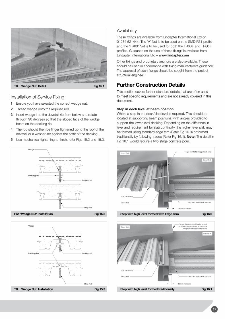
Step in deck level at beam positionWhere a step in the deck/slab level is required. This should be located at supporting beam positions, with angles provided to support the lower level decking. Depending on the difference in level and requirement for slab continuity, the higher level slab may be formed using standard edge trim (Refer Fig 16.0) or formed traditionally by following trades (Refer Fig 16.1). Note: The detail in Fig 16.1 would require a two stage concrete pour.
Step with high level formed with Edge Trim Fig 16.0
Step with high level formed traditionally Fig 16.1
17

Guidance NotesDecking on angles to beam websTo reduce the structural zone it is sometimes necessary to install the decking onto angles fixed to the beam webs (Refer page 25 and Fig 16.2). Where the decking spans parallel to the beam web, it may be possible depending on spacing of secondary beams to utilise a 2.0mm gauge flashing to avoid the requirement for a structural angle.
Decking on angle fixed to web of beam Fig 16.2
3D Stud Detail at Butt JointsPages 27-28 of this document shows the 2D standard details for shear stud configurations in accordance with BS5950 and Eurocode 4. Fig 16.3 is a 3D detail of the typical staggered stud configuration used at butt joints.
Shear Stud Detail at Butt Joints (TR+ profiles) Fig 16.3
Alternative detail for large overhangsWhere overhangs are required on edges parallel with the deck span, these are typically formed with standard edge trim (Refer pages 20 and 21). Where edge dimensions are in excess of figures shown in Table 3, temporary propping is required to the edge prior to installation. Alternatively, additional stub beams in line with secondary steels can be provided by the steelwork contractor. These large edges can then be formed in decking with trim stitched to the side (Refer Fig 16.4).
Large side cantilever with stub beams Fig 16.4
Support detail at Existing Concrete / Core WallsShelf angles are required where decking spans up against existing concrete or core walls (Refer Fig 16.5)
Decking on RSA fixed to Concrete Core Fig 16.5
18

Perimeter ToeboardPerimeter toeboard is usually provided as part of the edge protection system. However, in some instances it is necessary for this to be provided as an addition to the perimeter edge trim. When required, there are two common options:
Fig 16.6 – the toeboard consists of a flat trim fixed flush to the outer vertical face of the edge trim, for removal by others.
Perimeter Toeboard fixed to vertical face of trim Fig 16.6
Fig 16.7 – the toeboard is a secondary trim fixed to a horizontal leg provided along the top of the standard trim. This has limitations due to the access required to fix the edge trim to supporting steelwork, but is easier to remove upon completion.
Perimeter toeboard fixed to top leg of trim Fig 16.7
Edge trim to form outer face of upstandAlthough not a recommended detail, as it is easier for the outer and inner faces of perimeter upstands to be formed traditionally. In some instances where this is not practical, it is possible to provide extended height trim to form the outer face of the upstand (Refer Fig 16.8). The internal face of the upstand will still require traditional formwork by others. There are limitations on trim height and gauge, for further advice contact SMD Technical Department.
Edge trim to form outer face of upstand Fig 16.8
19

www.smdstockyards.co.uk(Ashbourne Site)Tel: +44 (0) 1335 300999 Tel: +44 (0) 1335 658548 Email: [email protected]
(Brentwood Site)Tel: +44 (0) 1277 812490 Tel: +44 (0) 1277 508778 Email: [email protected]
(Motherwell Site)Tel: +44 (0) 1698 622202 Email: [email protected]
Standard SMD Deck Drawing Layout Fig 17.0
A B
1
2
3000 3000
3000
427
100
100
1191
COB30
0
NS
B
B
TP TP
D3915
EOB
TP
TP
A
K
100B CA
Floor / Phase NoPack No
Pack weight
Floor / Phase NoTrim Pack No
Deck pack reference symbol Trim pack reference symbol
Z3 Z3 Z3
F1
Deck reference blockNo. of deck sheets Sheet length
Stud reference blockNo. of studs Pitch / c/c's of studs
Chain dotted line labelled TPindicates extent of temporary
propping required
Propped slab edge
Dimension from C beamto slab edge
Edge trim referenceRefer to trim legend
Cantilevered deck to formlarge slab edge
Flashing referenceRefer to trim legend
Hatching indicates pack loadingout location
Diagonal line with 'DeckReference Block' indicates thearea/coverage of deck assigned
Stud reference
B
'P' indicates studs in pairs'S' indicates staggered studs'R' Remainder studs to bedistributed starting at beam ends
L
Abbreviated terms found on SMD drawings:-
EOB = Edge of beamCOB = Centre of beamecc = Eccentric (distance from grid or other)
(This will indicate beam or SOP, not slab)
FLASHINGBUNDLE
X/F1
Floor / Phase NoFlashing Pack No
C
SOP = Setting out pointTOS = Top of steelSSL = Structural slab levelTP = Temporary Propping
Up
0.40t
1/01
50
Up
0.40t
1/01
50
SMD Site managers Ref
Typical Drawing Layout
(Head Office)Tel: +44 (0) 1202 714990Fax: +44 (0) 1202 714980 Email: [email protected]