steel vessels 2013 - ww2.eagle.orgww2.eagle.org/content/dam/eagle/rules-and-guides/archives/... ·...
TRANSCRIPT
P a r t 3 : H u l l C o n s t r u c t i o n a n d E q u i p m e n t
RULES FOR BUILDING AND CLASSING
STEEL VESSELS 2013
PART 3 HULL CONSTRUCTION AND EQUIPMENT
American Bureau of Shipping Incorporated by Act of Legislature of the State of New York 1862
Copyright 2012 American Bureau of Shipping ABS Plaza 16855 Northchase Drive Houston, TX 77060 USA

ii ABS RULES FOR BUILDING AND CLASSING STEEL VESSELS . 2013
R u l e C h a n g e N o t i c e ( 2 0 1 2 )
Rule Change Notice (2013) The effective date of each technical change since 1993 is shown in parenthesis at the end of the subsection/paragraph titles within the text of each Part. Unless a particular date and month are shown, the years in parentheses refer to the following effective dates:
(2000) and after 1 January 2000 (and subsequent years) (1996) 9 May 1996 (1999) 12 May 1999 (1995) 15 May 1995 (1998) 13 May 1998 (1994) 9 May 1994 (1997) 19 May 1997 (1993) 11 May 1993
Listing by Effective Dates of Changes from the 2012 Rules
Notice No. 1 (effective on 1 July 2012) to the 2012 rules, which is incorporated in the 2013 Rules, is summarized below.
EFFECTIVE DATE 1 July 2012 – shown as (1 July 2012) (based on the contract date for new construction between builder and Owner)
Part/Para. No. Title/Subject Status/Remarks 3-2-15/3.3 Vertical Design Pressures To align the Rules with IACS S21A “Evaluations and Scantlings of
Hatch Covers and Hatch Coamings and Closing Arrangements of Cargo Holds of Ships”. (Incorporates Notice No. 1)
3-2-15/Figure 1 (New)
Positions 1 and 2 To align the Rules with IACS S21A “Evaluations and Scantlings of Hatch Covers and Hatch Coamings and Closing Arrangements of Cargo Holds of Ships”. (Incorporates Notice No. 1)
3-2-15/Figure 2 (New)
Positions 1 and 2 for an Increased Freeboard
To align the Rules with IACS S21A “Evaluations and Scantlings of Hatch Covers and Hatch Coamings and Closing Arrangements of Cargo Holds of Ships”. (Incorporates Notice No. 1)
3-2-15/3.5 (New)
Horizontal Design Pressures To align the Rules with IACS S21A “Evaluations and Scantlings of Hatch Covers and Hatch Coamings and Closing Arrangements of Cargo Holds of Ships”. (Incorporates Notice No. 1)
3-2-15/Table 1 (New)
Minimum Design Load pHmin To align the Rules with IACS S21A “Evaluations and Scantlings of Hatch Covers and Hatch Coamings and Closing Arrangements of Cargo Holds of Ships”. (Incorporates Notice No. 1)
3-2-15/9 Hatchways Closed by Covers of Steel Fitted with Gaskets and Clamping Devices
To align the Rules with IACS S21A “Evaluations and Scantlings of Hatch Covers and Hatch Coamings and Closing Arrangements of Cargo Holds of Ships”. (Incorporates Notice No. 1)
3-2-15/Figure 3 (New)
Determination of Normal Stress of the Hatch Cover Plating
To align the Rules with IACS S21A “Evaluations and Scantlings of Hatch Covers and Hatch Coamings and Closing Arrangements of Cargo Holds of Ships”. (Incorporates Notice No. 1)
3-2-15/Figure 4 (New)
Forces due to Container Loads To align the Rules with IACS S21A “Evaluations and Scantlings of Hatch Covers and Hatch Coamings and Closing Arrangements of Cargo Holds of Ships”. (Incorporates Notice No. 1)
3-2-15/Figure 5 (New)
Partial Loading of a Container Hatch Cover
To align the Rules with IACS S21A “Evaluations and Scantlings of Hatch Covers and Hatch Coamings and Closing Arrangements of Cargo Holds of Ships”. (Incorporates Notice No. 1)
3-2-15/Table 2 (New)
Effective Breadth em of Plating of Primary Supporting Members
To align the Rules with IACS S21A “Evaluations and Scantlings of Hatch Covers and Hatch Coamings and Closing Arrangements of Cargo Holds of Ships”. (Incorporates Notice No. 1)
3-2-15/Figure 6 (New)
General Arrangement of Panel To align the Rules with IACS S21A “Evaluations and Scantlings of Hatch Covers and Hatch Coamings and Closing Arrangements of Cargo Holds of Ships”. (Incorporates Notice No. 1)

ABS RULES FOR BUILDING AND CLASSING STEEL VESSELS . 2013 iii
Part/Para. No. Title/Subject Status/Remarks 3-2-15/Table 3 (New)
Correction Factor F1 To align the Rules with IACS S21A “Evaluations and Scantlings of Hatch Covers and Hatch Coamings and Closing Arrangements of Cargo Holds of Ships”. (Incorporates Notice No. 1)
3-2-15/Table 4 (New)
Coefficients e1, e2, e3 and Factor B To align the Rules with IACS S21A “Evaluations and Scantlings of Hatch Covers and Hatch Coamings and Closing Arrangements of Cargo Holds of Ships”. (Incorporates Notice No. 1)
3-2-15/Table 5 (New)
Buckling and Reduction Factors for Plane Elementary Plate Panels
To align the Rules with IACS S21A “Evaluations and Scantlings of Hatch Covers and Hatch Coamings and Closing Arrangements of Cargo Holds of Ships”. (Incorporates Notice No. 1)
3-2-15/Figure 7 (New)
Stiffening Parallel to Web of Primary Supporting Member
To align the Rules with IACS S21A “Evaluations and Scantlings of Hatch Covers and Hatch Coamings and Closing Arrangements of Cargo Holds of Ships”. (Incorporates Notice No. 1)
3-2-15/Figure 8 (New)
Stiffening Perpendicular to Web of Primary Supporting Member
To align the Rules with IACS S21A “Evaluations and Scantlings of Hatch Covers and Hatch Coamings and Closing Arrangements of Cargo Holds of Ships”. (Incorporates Notice No. 1)
3-2-15/Figure 9 (New)
Dimensions of Stiffeners To align the Rules with IACS S21A “Evaluations and Scantlings of Hatch Covers and Hatch Coamings and Closing Arrangements of Cargo Holds of Ships”. (Incorporates Notice No. 1)
3-2-15/Table 6 (New)
Moments of Inertia To align the Rules with IACS S21A “Evaluations and Scantlings of Hatch Covers and Hatch Coamings and Closing Arrangements of Cargo Holds of Ships”. (Incorporates Notice No. 1)
3-2-15/Figure 10 (New)
Example for Arrangement of Coaming Plates
To align the Rules with IACS S21A “Evaluations and Scantlings of Hatch Covers and Hatch Coamings and Closing Arrangements of Cargo Holds of Ships”. (Incorporates Notice No. 1)
3-2-15/Figure 11 (New)
Lifting Forces at a Hatch Cover To align the Rules with IACS S21A “Evaluations and Scantlings of Hatch Covers and Hatch Coamings and Closing Arrangements of Cargo Holds of Ships”. (Incorporates Notice No. 1)
3-2-15/Table 7 (New)
Permissible Nominal Surface Pressure pn
To align the Rules with IACS S21A “Evaluations and Scantlings of Hatch Covers and Hatch Coamings and Closing Arrangements of Cargo Holds of Ships”. (Incorporates Notice No. 1)
3-2-15/Table 8 (New)
Corrosion Additions tS for Hatch Covers and Hatch Coamings
To align the Rules with IACS S21A “Evaluations and Scantlings of Hatch Covers and Hatch Coamings and Closing Arrangements of Cargo Holds of Ships”. (Incorporates Notice No. 1)
3-2-15/21.5 Escape Openings To align the requirements for escape openings with IACS UI SC 247, “Emergency Exit Hatches to Open Deck”. (Incorporates Notice No. 1)
3-2-15/21.11 Chain Pipe Opening To align the Rules with recent revisions to IACS UR L4 Rev 3 Corr 1, revised August 2011, that provides examples of acceptable arrangements of closing chain pipe openings. (Incorporates Notice No. 1)
3-2-18/5 Corrosion Protection of Steel To remove requirements pertaining to corrosion protection of "Salt Water Ballast Tanks and Double-side Skin Spaces" (section 5.3), "Cargo Oil Tanks of Crude Oil Tankers" (section 5.5) and "Void Spaces" (section 5.9) which are addressed by specific and more detailed SOLAS regulations (SOLAS II-1/3-2 & SOLAS II-1/3-11), so as to avoid confusion and conflict with respect to the application of the SOLAS regulations. (Incorporates Notice No. 1)
3-3-A3/11.1 Conditions of Approval of the Onboard Software for Stability Calculations
To ensure the stability software is available if the primary computer crashes. (Incorporates Notice No. 1)

iv ABS RULES FOR BUILDING AND CLASSING STEEL VESSELS . 2013
EFFECTIVE DATE 1 January 2013 – shown as (2013) (based on the contract date for new construction between builder and Owner)
Part/Para. No. Title/Subject Status/Remarks 3-1-2/5.3 Reduced Scantlings with Protective
Coatings The incorporation of Performance Standards for Protective Coatings (PSPC) requirements in modern shipbuilding has removed the need for special consideration of protective coatings.
3-2-11/3.1 General To clarify that requirements for openings and closing appliances in deckhouses are the same as those for superstructures.
3-2-11/5 Enclosed Superstructures and Deckhouses
To clarify that requirements for openings and closing appliances in deckhouses are the same as those for superstructures.
3-3-A2/1.3 Applicability To align the requirements with IMO Resolution MSC.170 (79), which adds information about Double Side Skin Bulk carriers.

ABS RULES FOR BUILDING AND CLASSING STEEL VESSELS . 2013 v
P A R T T a b l e o f C o n t e n t s
3 Hull Construction and Equipment
CONTENTS CHAPTER 1 General .................................................................................................... 1
Section 1 Definitions .............................................................................. 3 Section 2 General Requirements ........................................................... 6
CHAPTER 2 Hull Structures and Arrangements ..................................................... 12
Section 1 Longitudinal Strength ........................................................... 31 Section 2 Shell Plating ......................................................................... 61 Section 3 Decks ................................................................................... 70 Section 4 Bottom Structures ................................................................ 77 Section 5 Frames ................................................................................. 87 Section 6 Web Frames and Side Stringers .......................................... 94 Section 7 Beams .................................................................................. 98 Section 8 Pillars, Deck Girders and Transverses .............................. 104 Section 9 Watertight Bulkheads and Doors ....................................... 111 Section 10 Deep Tanks ........................................................................ 123 Section 11 Superstructures, Deckhouses and Helicopter Decks ........ 127 Section 12 Machinery Space and Tunnel ............................................ 134 Section 13 Stems, Stern Frames and Rudder Horns .......................... 136 Section 14 Rudders and Steering Equipment ...................................... 147 Section 15 Protection of Deck Openings ............................................. 181 Section 16 Protection of Shell Openings ............................................. 229 Section 17 Bulwarks, Rails, Freeing Ports, Portlights and
Ventilators .......................................................................... 242 Section 18 Ceiling, Sparring and Protection of Steel ........................... 251 Section 19 Weld Design ....................................................................... 253 Appendix 1 Calculation of Shear Stresses for Vessels Having
Longitudinal Bulkheads ........................................................ 44 Appendix 2 Loading Manuals and Loading Instruments ......................... 46 Appendix 3 Loading Manuals and Loading Instruments: Additional
Requirements for Bulk Carriers, Ore Carriers and Combination Carriers 150 meters (492 feet) and Above in Length (Lf) ............................................................. 50
Appendix 4 Buckling Strength of Longitudinal Strength Members ......... 55 Appendix 5 Guidelines for Calculating Bending Moment and Shear
Force in Rudders and Rudder Stocks ................................ 176 Appendix 6 Portable Beams and Hatch Cover Stiffeners of Variable
Cross Section ..................................................................... 227

vi ABS RULES FOR BUILDING AND CLASSING STEEL VESSELS . 2013
CHAPTER 3 Subdivision and Stability ................................................................... 261
Section 1 General Requirements ....................................................... 263
Appendix 1 Intact Stability of Tankers During Liquid Transfer Operations ......................................................................... 265
Appendix 2 Subdivision and Damage Stability Requirements for Bulk Carriers ...................................................................... 268
Appendix 3 Onboard Computers for Stability Calculations ................... 269
CHAPTER 4 Fire Safety Measures .......................................................................... 276
Section 1 Structural Fire Protection ................................................... 277
CHAPTER 5 Equipment ........................................................................................... 279
Section 1 Anchoring, Mooring and Towing Equipment ...................... 281
Section 2 Mooring of Oil Carriers at Single Point Moorings .............. 298
CHAPTER 6 Navigation ........................................................................................... 301
Section 1 Visibility .............................................................................. 302
CHAPTER 7 Testing, Trials and Surveys During Construction – Hull ................ 306
Section 1 Tank, Bulkhead and Rudder Tightness Testing ................ 308
Section 2 Trials .................................................................................. 315
Section 3 Surveys .............................................................................. 316

ABS RULES FOR BUILDING AND CLASSING STEEL VESSELS . 2013 1
P A R T C h a p t e r 1 : G e n e r a l
3 C H A P T E R 1 General
CONTENTS SECTION 1 Definitions ............................................................................................... 3
1 Application .......................................................................................... 3 3 Length ................................................................................................. 3
3.1 Scantling Length (L) ........................................................................ 3 3.3 Freeboard Length (Lf) ...................................................................... 3
5 Breadth (B) .......................................................................................... 3 7 Depth ................................................................................................... 4
7.1 Molded Depth (D) ............................................................................ 4 7.3 Scantling Depth (Ds) ........................................................................ 4
9 Draft (d) ............................................................................................... 4 11 Molded Displacement and Block Coefficient ...................................... 4
11.1 Molded Displacement (∆) ................................................................ 4 11.3 Block Coefficient (Cb) ....................................................................... 4
13 Decks .................................................................................................. 4 13.1 Freeboard Deck ............................................................................... 4 13.3 Bulkhead Deck ................................................................................ 4 13.5 Strength Deck .................................................................................. 4 13.7 Superstructure Deck ........................................................................ 5
15 Deadweight (DWT) and Lightship Weight ........................................... 5 17 Units .................................................................................................... 5 FIGURE 1 ......................................................................................................... 3
SECTION 2 General Requirements ........................................................................... 6
1 Material and Fabrication ..................................................................... 6 1.1 Material ............................................................................................ 6 1.3 Application ....................................................................................... 6
3 Application of Steel Materials 51.0 mm (2.00 in.) and Under in Thickness ............................................................................................ 7 3.1 Selection of Material Grade ............................................................. 7 3.3 Note for Users ................................................................................. 7
5 Scantlings ........................................................................................... 9 5.1 General............................................................................................ 9 5.3 Dynamic Loading Approach ............................................................ 9
7 Proportions ........................................................................................ 10 9 Workmanship .................................................................................... 10 11 Drydocking ........................................................................................ 10

2 ABS RULES FOR BUILDING AND CLASSING STEEL VESSELS . 2013
13 Structural Sections ............................................................................ 10 13.1 General .......................................................................................... 10 13.3 Deep Supporting Members ............................................................ 10 13.5 Frames, Beams and Stiffeners ...................................................... 10
15 Structural Design Details .................................................................. 11 15.1 General .......................................................................................... 11 15.3 Termination of Structural Members ................................................ 11 15.5 Fabrication ..................................................................................... 11
TABLE 1 Material Grades ......................................................................... 7 TABLE 2 Material Class or Grade of Structural Members ....................... 8

ABS RULES FOR BUILDING AND CLASSING STEEL VESSELS . 2013 3
P A R T S e c t i o n 1 : D e f i n i t i o n s
3 C H A P T E R 1 General
S E C T I O N 1 Definitions
1 Application The following definitions of symbols and terms are to be understood (in the absence of other specifications) where they appear in the Rules.
3 Length
3.1 Scantling Length (L) (1997) L is the distance in meters (feet) on the summer load line from the fore side of the stem to the centerline of the rudder stock. For use with the Rules, L is not to be less than 96% and need not be greater than 97% of the length on the summer load line. The forward end of L is to coincide with the fore side of the stem on the waterline on which L is measured.
3.3 Freeboard Length (Lf) (2002) Lf is the distance in meters (feet) on a waterline at 85% of the least molded depth measured from the top of the keel from the fore side of the stem to the centerline of the rudder stock or 96% of the length on that waterline, whichever is greater. Where the stem is a fair concave curve above the waterline at 85% of the least molded depth and where the aftermost point of the stem is above the waterline, the forward end of the length, Lf, is to be taken at the aftermost point of the stem above that waterline. See 3-1-1/Figure 1.
FIGURE 1
0.85DD
Lf
FBD Deck
F.P.
∆
5 Breadth (B) B is the greatest molded breadth in meters (feet).

Part 3 Hull Construction and Equipment Chapter 1 General Section 1 Definitions 3-1-1
4 ABS RULES FOR BUILDING AND CLASSING STEEL VESSELS . 2013
7 Depth
7.1 Molded Depth (D) (1997) D is the molded depth at side in meters (feet) measured at the middle of L from the molded base line to the top of the freeboard-deck beams. In vessels having rounded gunwales, D is to be measured to the point of intersection of the molded lines of the deck and side shell plating. In cases where watertight bulkheads extend to a deck above the freeboard deck and are to be recorded in the Record as effective to that deck, D is to be measured to the bulkhead deck.
7.3 Scantling Depth (Ds) (1997) The depth Ds for use with scantling requirements is the distance in meters (feet) from the molded base line to the strength deck as defined in 3-1-1/13.5.
9 Draft (d) d is the molded draft, and is the distance in meters (feet) from the molded base line to the summer load line.
11 Molded Displacement and Block Coefficient (1997)
11.1 Molded Displacement (∆) ∆ is the molded displacement of the vessel in metric tons (long tons), excluding appendages, taken at the summer load line.
11.3 Block Coefficient (Cb) Cb is the block coefficient obtained from the following equation:
Cb = ∆/1.025LBwl d (SI & MKS units)
Cb = 35∆/LBwl d (US units)
where
∆ = molded displacement, as defined in 3-1-1/11.1.
L = scantling length, as defined in 3-1-1/3.1
d = draft, as defined in 3-1-1/9
Bwl = the greatest molded breadth at summer load line
13 Decks
13.1 Freeboard Deck The freeboard deck normally is the uppermost continuous deck having permanent means for closing all openings. Where a vessel is designed for a special draft, considerably less than that corresponding to the least freeboard obtainable under the International Load Line Regulations, the freeboard deck, for the purpose of the Rules, may be taken as the actual lowest deck from which the draft can be obtained under those regulations.
13.3 Bulkhead Deck The bulkhead deck is the highest deck to which the watertight bulkheads extend and are made effective.
13.5 Strength Deck The strength deck is the deck that forms the top of the effective hull girder at any part of its length. See 3-2-1/11.1.

Part 3 Hull Construction and Equipment Chapter 1 General Section 1 Definitions 3-1-1
ABS RULES FOR BUILDING AND CLASSING STEEL VESSELS . 2013 5
13.7 Superstructure Deck A superstructure deck is a deck above the freeboard deck to which the side shell plating extends. Except where otherwise specified, the term “superstructure deck” where used in the Rules refers to the first such deck above the freeboard deck.
15 Deadweight (DWT) and Lightship Weight (1997) For the purpose of these Rules, deadweight, DWT, is the difference in metric tons (long tons) between the displacement of the vessel at its summer load line in water having a specific gravity of 1.025 and the lightship weight. For the purpose of these Rules, lightship weight is the displacement of the vessel in metric tons (long tons) with no cargo, fuel, lubricating oil, ballast water, fresh water nor feed water in tanks, no consumable stores, and no passengers or crew nor their effects.
17 Units These Rules are written in three systems of units, viz., SI units, MKS units and US customary units. Each system is to be used independently of any other system.
Unless indicated otherwise, the format of presentation in the Rules of the three systems of units is as follows:
SI units (MKS units, US customary units)

6 ABS RULES FOR BUILDING AND CLASSING STEEL VESSELS . 2013
P A R T S e c t i o n 2 : G e n e r a l R e q u i r e m e n t s
3 C H A P T E R 1 General
S E C T I O N 2 General Requirements
1 Material and Fabrication
1.1 Material 1.1.1 Steel
These Rules are intended for vessels of welded construction using steels complying with the requirements of Part 2, Chapter 1. Use of steels other than those in Part 2, Chapter 1 and the vessels’ corresponding scantlings will be specially considered.
1.1.2 Aluminum Alloys The use of aluminum alloys in hull structures will be considered upon submission of a specification of the proposed alloys and their proposed method of fabrication.
1.1.3 Design Consideration Where scantlings are reduced in association with the use of higher-strength steel or where aluminum alloys are used, adequate buckling strength is to be provided. Where it is intended to use material of cold flanging quality for important longitudinal strength members, this steel is to be indicated on the plans.
1.1.4 Guidance for Repair Where a special welding procedure is required for special steels used in the construction, including any low temperature steel and those materials not encompassed in Part 2, Chapter 1, a set of plans showing the following information for each steel is to be placed aboard the vessel:
• Material Specification
• Welding procedure
• Location and extent of application
These plans are in addition to those normally placed aboard the vessel, and are to show all material applications.
1.3 Application The requirements of the Rules apply to steel vessels of all welded construction. Riveted hull construction, where used, is to comply with the applicable parts dealing with riveting in the 1969 edition of the Rules.

Part 3 Hull Construction and Equipment Chapter 1 General Section 2 General Requirements 3-1-2
ABS RULES FOR BUILDING AND CLASSING STEEL VESSELS . 2013 7
3 Application of Steel Materials 51.0 mm (2.00 in.) and Under in Thickness
3.1 Selection of Material Grade Steel materials for particular locations are not to be of lower grades than those required by 3-1-2/Table 1 for the material class given in 3-1-2/Table 2.
3.3 Note for Users The attention of users is drawn to the fact that when fatigue loading is present, the effective strength of higher-strength steel in welded construction may not be greater than that of ordinary-strength steel.
Precautions against corrosion fatigue may also be necessary.
TABLE 1 Material Grades (2000)
Thickness t mm (in.)
Material Class
I II III
t ≤ 15 (t ≤ 0.60) A(2), AH A, AH A, AH
15 < t ≤ 20 (0.60 < t ≤ 0.79) A, AH A, AH B, AH
20 < t ≤ 25 (0.79 < t ≤ 0.98) A, AH B, AH D, DH
25 < t ≤ 30 (0.98 < t ≤ 1.18) A, AH D, DH D (1), DH
30 < t ≤ 35 (1.18 < t ≤ 1.38) B, AH D, DH E, EH
35 < t ≤ 40 (1.38 < t ≤ 1.57) B, AH D, DH E, EH
40 < t ≤ 51 (1.57 < t ≤ 2.00) D, DH E, EH E, EH
Notes 1 Grade D, of these thicknesses, is to be normalized.
2 ASTM A36 steel otherwise tested and certified to the satisfaction of ABS may be used in lieu of Grade A for a thickness up to and including 12.5 mm (0.5 in.) for plate and up to and including 40 mm (1.57 in.) for sections.

Part 3 Hull Construction and Equipment Chapter 1 General Section 2 General Requirements 3-1-2
8 ABS RULES FOR BUILDING AND CLASSING STEEL VESSELS . 2013
TABLE 2 Material Class or Grade of Structural Members (1 July 2009)
Line No. Structural Members
Within 0.4L Amidships Outside 0.4L amidships Material Class(8) or Grade Material Class or Grade
A Secondary A1 Longitudinal bulkhead strakes, other than those belonging to the
Primary category I A(10)/AH A2 Deck plating exposed to weather, other than that belonging to
the Primary or Special category A3 Side plating (12) B Primary B1 Bottom plating, including keel plate
II A(10)/AH
B2 Strength deck plating, excluding that belonging to the Special category (13)
B3 Continuous longitudinal members above strength deck, excluding hatch coamings (13)
B4 Uppermost strake in longitudinal bulkhead B5 Vertical strake (hatch side girder) and uppermost sloped strake
in top wing tank C Special C1 Sheer strake at strength deck (1, 9, 13)
III II
(I outside 0.6L amidships)
C2 Stringer plate in strength deck (1, 9, 13) C3 Deck strake at longitudinal bulkhead (2, 9, 13) C4 Strength deck plating at outboard corners of cargo hatch openings
in container carriers and other ships with similar hatch opening configurations (3, 13)
C5 Strength deck plating at corners of cargo hatch openings in bulk carriers, ore carriers, combination carriers and other ships with similar hatch opening configurations (4, 13)
C6 Bilge strake (5, 6, 9) C7 Longitudinal hatch coamings of length greater than 0.15L (7)
C8 End brackets and deck house transition of longitudinal cargo hatch coamings (7)
D Other Categories D1 Stern frames, rudder horns, rudders and shaft brackets - II(11)
D2 Strength members not referred to in A to C and D1 A(10)/AH A(10)/AH

Part 3 Hull Construction and Equipment Chapter 1 General Section 2 General Requirements 3-1-2
ABS RULES FOR BUILDING AND CLASSING STEEL VESSELS . 2013 9
TABLE 2 (continued) Material Class or Grade of Structural Members (1 July 2009)
Notes: 1 Not to be less than grade E/EH(9) within 0.4L amidships in ships with length exceeding 250 m (820 ft).
2 Excluding deck plating in way of inner-skin bulkhead of double hull ships.
3 Not to be less than class III within the length of the cargo region.
4 Not to be less than class III within 0.6L amidships and class II within the remaining length of the cargo region.
5 May be of class II in ships with a double bottom over the full breadth and with length less than 150 m (492 ft).
6 Not to be less than grade D/DH within 0.4L amidships in ships with length exceeding 250 m (820 ft).
7 Not to be less than grade D/DH.
8 Special consideration will be given to vessels of restricted class.
9 Single strake required to be class III or E/EH are to have breadths not less than 800 + 5L mm (31.5 + 0.06L in.), but need not exceed 1800 mm (71 in.), unless limited by the geometry of the vessel’s design.
10 ASTM A36 steel otherwise tested and certified to the satisfaction of ABS may be used in lieu of Grade A for a thickness up to and including 12.5 mm (0.5 in.) for plates and up to and including 40 mm (1.57 in.) for sections.
11 For rudder and rudder body plates subjected to stress concentrations (e.g., in way of lower support or at upper part of spade rudders), class III is to be applied.
12 (1 July 2009) Single side strakes for ships exceeding 150 m (492 feet) without inner continuous longitudinal; bulkheads between bottom and the single strength deck are not to be less than grade B/AH within cargo region in ships.
13 (1 July 2009) Not to be less than grade B/AH within 0.4L amidships in ships with length exceeding 150 m (492 feet) and single strength deck.
5 Scantlings (2013)
5.1 General The midship scantlings specified in the Rules are to apply throughout the midship 0.4L. End scantlings are not to extend for more than 0.1L from each end of the vessel. Reduction in scantlings from the midship to the end scantlings is to be effected in as gradual a manner as practicable. Sections having appropriate section moduli or areas, in accordance with their functions in the structure as stiffeners, columns or combinations of both, are to be adopted, due regard being given to the thickness of all parts of the sections to provide a proper margin for corrosion. It may be required that calculations be submitted in support of resistance to buckling for any part of the vessel’s structure.
5.3 Dynamic Loading Approach The symbols SH-DLA are assigned to vessels which have been reviewed based upon an acceptable load and structural analysis procedure, taking into consideration the dynamic load components acting on the vessel.
The dynamic load components considered are to include the external hydrodynamic pressure loads, dynamic loads from cargoes and inertial loads of the hull structure. The magnitude of the load components and their combinations are to be determined from appropriate ship motion response calculations for loading conditions which represent the envelope of maximum dynamically induced stresses in the vessel.
The adequacy of the hull structure for all combinations of the dynamic loadings is to be evaluated using an acceptable finite element analysis method.
In no case are the structural scantlings to be less than those obtained from other requirements in the Rules.

Part 3 Hull Construction and Equipment Chapter 1 General Section 2 General Requirements 3-1-2
10 ABS RULES FOR BUILDING AND CLASSING STEEL VESSELS . 2013
7 Proportions In general, these Rules are valid for all vessels not exceeding 500 m (1640 ft) in length, L, and having a breadth, B, not exceeding one-fifth of the length, L, nor 2.5 times the depth, Ds, to the strength deck. Vessels beyond these proportions will be specially considered.
9 Workmanship (2008) All workmanship is to be of commercial marine quality and acceptable to the Surveyor. Welding is to be in accordance with the requirements of Part 2, Chapter 4. See also 3-7-3/1.
11 Drydocking Consideration is to be given to drydocking the vessel within twelve months after delivery. For vessels 228.5 m (750 ft) in length, L, and over, information indicating docking arrangements is to be prepared and furnished onboard the vessel for guidance.
13 Structural Sections (1993)
13.1 General The scantling requirements of these Rules are applicable to structural angles, channels, bars, and rolled or built-up sections.
13.3 Deep Supporting Members (1993) The required section modulus of members such as girders, webs, etc., supporting frames, beams and stiffeners, is to be obtained on an effective width of plating basis in accordance with this subsection. The section is to include the structural member in association with an effective width of plating not exceeding one-half of the sum of the spacing on each side of the member or 33% of the unsupported span , whichever is less. For girders and webs along hatch openings, an effective breadth of plating not exceeding one-half of the spacing or 16.5% of the unsupported span , whichever is less, is to be used.
13.5 Frames, Beams and Stiffeners (1993) 13.5.1 Section Modulus
The required section modulus is to be provided by the stiffener and a maximum of one frame space of the plating to which it is attached.
13.5.2 Web Thickness The depth to thickness ratio of the web portion of members is not to exceed the following:
Members with flange 50C1C2 Members without flange 15C1C2
where
C1 = 0.95 (horizontal web within a tank)
= 1.0 (all other cases)
C2 = 1.0 (ordinary strength steel)
= 0.92 (HT32)
= 0.90 (HT36)

Part 3 Hull Construction and Equipment Chapter 1 General Section 2 General Requirements 3-1-2
ABS RULES FOR BUILDING AND CLASSING STEEL VESSELS . 2013 11
15 Structural Design Details
15.1 General The designer is to give consideration to the following:
i) The thickness of internals in locations susceptible to rapid corrosion.
ii) The proportions of built-up members for compliance with established standards for structural stability. See 3-1-2/13.5.2 and Appendix 3-2-A4.
iii) The design of structural details, such as noted below, against the harmful effects of stress concentrations and notches:
Details of the ends, at the intersections of members and associated brackets.
Shape and location of air, drainage, and/or lightening holes.
Shape and reinforcement of slots or cut-outs for internals.
Elimination or closing of weld scallops in way of butts, “softening” of bracket toes, reducing abrupt changes of section or structural discontinuities.
iv) Proportions and thickness of structural members to reduce fatigue response due to engine, propeller or wave-induced cyclic stresses, particularly for higher-strength steels.
A booklet of standard construction details based on the above considerations is to be submitted for review and comment.
15.3 Termination of Structural Members (1998) Unless permitted elsewhere in the Rules, structural members are to be effectively connected to adjacent structures in such a manner as to avoid hard spots, notches and other harmful stress concentrations.
Where load-bearing members are not required to be attached at their ends, special attention is to be given to the end taper, by using a sniped end of not more than 30°.
Where the member has a face bar or flange, it is to be sniped and tapered not more than 30°.
The end brackets of large primary load-bearing members are to be soft-toed. Where any end bracket has a face bar it is to be sniped and tapered not more than 30°.
Bracket toes and sniped end members are to be kept within 25 mm (1.0 in.) of the adjacent member, unless the bracket or member is supported by another member on the opposite side of the plating. The depth of toe or sniped end is generally not to exceed 15 mm (0.60 in.).
Where a strength deck or shell longitudinal terminates without an end attachment, the longitudinal is to extend into the adjacent transversely framed structure, or stop at a local transverse member fitted at about one transverse frame space (see 3-2-5/1.5) beyond the last floor or web that supports the longitudinal.
The end attachments of non-load bearing members may, in general, be snipe ended. The sniped end is to be not more than 30° and is to be kept generally within 40 mm (1.57 in.) of the adjacent member unless it is supported by a member on the opposite side of the plating. The depth of the toe is generally not to exceed 15 mm (0.6 in.).
15.5 Fabrication (1 July 2011) Structural fabrication is to be carried out in accordance with a recognized standard to the satisfaction of the attending Surveyor. If a recognized national standard or an appropriate shipbuilding and repair standard is not available, the latest version of IACS Recommendation No. 47 “Shipbuilding and Repair Quality Standard”, may be used. See Part 5C, Appendix 1 “SafeHull Construction Monitoring Program”.
12 ABS RULES FOR BUILDING AND CLASSING STEEL VESSELS . 2013
P A R T C h a p t e r 2 : H u l l S t r u c t u r e s a n d A r r a n g e m e n t s
3 C H A P T E R 2 Hull Structures and Arrangements
CONTENTS SECTION 1 Longitudinal Strength .......................................................................... 31
1 Application ......................................................................................... 31 3 Longitudinal Hull Girder Strength ...................................................... 31
3.1 Sign Convention of Bending Moment and Shear Force ................. 31 3.3 Still-water Bending Moment and Shear Force ............................... 31 3.5 Wave Loads ................................................................................... 33 3.7 Bending Strength Standard ............................................................ 36 3.9 Shearing Strength .......................................................................... 37
5 Longitudinal Strength with Higher-Strength Materials ...................... 39 5.1 General .......................................................................................... 39 5.3 Hull Girder Moment of Inertia ......................................................... 39 5.5 Hull Girder Section Modulus .......................................................... 39 5.7 Hull girder Shearing Force ............................................................. 39
7 Loading Guidance ............................................................................. 39 7.1 Loading Manual and Loading Instrument ....................................... 39 7.3 Allowable Stresses ........................................................................ 39
9 Section Modulus Calculation ............................................................. 40 9.1 Items Included in the Calculation ................................................... 40 9.3 Effective Areas Included in the Calculation .................................... 40 9.5 Section Modulus to the Deck or Bottom ......................................... 40 9.7 Section Modulus to the Top of Hatch Coamings ............................ 40
11 Strength Decks.................................................................................. 41 11.1 Definition ........................................................................................ 41 11.3 Tapering of Deck Sectional Areas ................................................. 41
13 Continuous Longitudinal Hatch Coamings and Above Deck Girders .............................................................................................. 41
15 Effective Lower Decks ...................................................................... 41 17 Longitudinal Deck Structures Inboard of Lines of Openings ............ 41
17.1 General .......................................................................................... 41 17.3 Effectiveness ................................................................................. 42
19 Buckling Strength .............................................................................. 42 FIGURE 1 Sign Convention ...................................................................... 34 FIGURE 2 Distribution Factor M ............................................................... 34 FIGURE 3 Distribution Factor F1 ............................................................... 35 FIGURE 4 Distribution Factor F2 ............................................................... 35 FIGURE 5 Shear Force Distribution ......................................................... 38 FIGURE 6 Effective Area of Hull Girder Members ................................... 43

ABS RULES FOR BUILDING AND CLASSING STEEL VESSELS . 2013 13
SECTION 2 Shell Plating .......................................................................................... 61 1 Application ........................................................................................ 61 3 Shell Plating Amidships .................................................................... 61
3.1 Vessels with No Partial Superstructures Above Uppermost Continuous Deck ........................................................................... 61
3.3 Superstructures Fitted Above Uppermost Continuous Deck (Side Plating Extended) ................................................................. 61
3.5 Superstructures Fitted Above Uppermost Continuous Deck (Side Plating Not Extended) ........................................................... 61
3.7 In Way of Comparatively Short Superstructures ............................ 61 3.9 Side Shell Plating .......................................................................... 62 3.11 Sheer Strake ................................................................................. 62 3.13 Bottom Shell Plating Amidships ..................................................... 62 3.15 Flat Plate Keel ............................................................................... 64 3.17 Minimum Thickness ....................................................................... 64
5 Shell Plating at Ends ......................................................................... 65 5.1 Minimum Shell Plating Thickness .................................................. 65 5.3 Immersed Bow Plating................................................................... 65 5.5 Bottom Forward ............................................................................. 66 5.7 Forecastle Side Plating ................................................................. 66 5.9 Poop Side Plating .......................................................................... 66 5.11 Bow and Stern Thruster Tunnels ................................................... 67 5.13 Special Heavy Plates .................................................................... 67
7 Bottom Shell Plating for Special Docking Arrangement ................... 67 9 Compensation ................................................................................... 68 11 Breaks ............................................................................................... 68 13 Bilge Keels ........................................................................................ 68 15 Higher-strength Materials .................................................................. 68
15.1 General.......................................................................................... 68 15.3 Bottom Plating of Higher-strength Material .................................... 69 15.5 Side Plating of Higher-strength Material ........................................ 69 15.7 End Plating .................................................................................... 69
SECTION 3 Decks..................................................................................................... 70
1 General ............................................................................................. 70 1.1 Extent of Plating ............................................................................ 70
3 Hull Girder Strength .......................................................................... 70 3.1 Longitudinal Section Modulus Amidships ...................................... 70 3.3 Strength Deck ................................................................................ 70 3.5 Longitudinally Framed Decks ........................................................ 70 3.7 Superstructure Decks .................................................................... 70 3.9 Deck Transitions ............................................................................ 70 3.11 Deck Plating .................................................................................. 71
5 Deck Plating ...................................................................................... 71 5.1 Thickness ...................................................................................... 71 5.3 Effective Lower Decks ................................................................... 71 5.5 Reinforcement at Openings ........................................................... 71 5.7 Platform Decks .............................................................................. 71

14 ABS RULES FOR BUILDING AND CLASSING STEEL VESSELS . 2013
5.9 Superstructure Decks .................................................................... 71 5.11 Decks Over Tanks ......................................................................... 71 5.13 Watertight Flats .............................................................................. 72 5.15 Retractable Tween Decks .............................................................. 72 5.17 Wheel Loading ............................................................................... 72
7 Higher-strength Material ................................................................... 75 7.1 Thickness ....................................................................................... 75 7.3 Wheel Loading ............................................................................... 76
9 Deck Covering Compositions ............................................................ 76 TABLE 1 Applicable Thickness Equations ............................................. 73 TABLE 2 Minimum Thickness Equations ............................................... 74 FIGURE 1 Wheel Loading Curves of “K” .................................................. 75
SECTION 4 Bottom Structures ................................................................................ 77
1 Double Bottoms................................................................................. 77 1.1 General .......................................................................................... 77 1.3 Testing ........................................................................................... 77
3 Center and Side Girders ................................................................... 77 3.1 Center Girders ............................................................................... 77 3.3 Pipe Tunnels (Note: An alternative arrangement of center
girders) ........................................................................................... 78 3.5 Docking Brackets (Note: Not only for center girder but also for
side girders) ................................................................................... 78 3.7 Side Girders ................................................................................... 78
5 Solid Floors ....................................................................................... 79 5.1 General .......................................................................................... 79 5.3 Tank-end Floors ............................................................................. 79 5.5 Floor Stiffeners .............................................................................. 79
7 Open Floors ...................................................................................... 80 7.1 General .......................................................................................... 80 7.3 Frames and Reverse Frames ........................................................ 80 7.5 Center and Side Brackets .............................................................. 80 7.7 Struts ............................................................................................. 80
9 Inner-bottom Plating .......................................................................... 81 9.1 Inner-bottom Plating Thickness ..................................................... 81 9.3 Center Strakes ............................................................................... 81 9.5 Under Boilers ................................................................................. 81 9.7 In Way of Engine Bed Plates or Thrust Blocks .............................. 81 9.9 Margin Plates ................................................................................. 82 9.11 Recommendations Where Cargo is Handled by Grabs ................. 82 9.13 Wheel Loading ............................................................................... 82
11 Bottom and Inner-bottom Longitudinals ............................................ 82 11.1 General .......................................................................................... 82 11.3 Bottom Longitudinals ..................................................................... 82 11.5 Inner-bottom Longitudinals ............................................................ 83
ABS RULES FOR BUILDING AND CLASSING STEEL VESSELS . 2013 15
13 Fore-end Strengthening .................................................................... 83 13.1 General.......................................................................................... 83 13.3 Extent of Strengthening ................................................................. 83 13.5 Longitudinal Framing ..................................................................... 83 13.7 Transverse Framing ...................................................................... 84
15 Higher-strength Materials .................................................................. 84 15.1 General.......................................................................................... 84 15.3 Inner-bottom Plating ...................................................................... 85 15.5 Bottom and Inner-bottom Longitudinals ......................................... 85 15.7 Center Girders, Side Girders, and Floors ...................................... 85
17 Structural Arrangements and Details ................................................ 85 17.1 Structural Sea Chests ................................................................... 85 17.3 Drainage ........................................................................................ 85 17.5 Manholes and Lightening Holes .................................................... 86 17.7 Air and Drainage Holes ................................................................. 86 17.9 Fixed Ballast .................................................................................. 86
TABLE 1 ......................................................................................................... 84 TABLE 2 Spacing of Floors .................................................................... 84 FIGURE 1 Double-bottom Solid Floors .................................................... 79 FIGURE 2 Double-bottom Open Floors .................................................... 81
SECTION 5 Frames .................................................................................................. 87
1 General ............................................................................................. 87 1.1 Basic Considerations ..................................................................... 87 1.3 Holes in Frames ............................................................................ 87 1.5 End Connections ........................................................................... 87 1.7 Standard and Cant Frame Spacing ............................................... 87
3 Hold Frames ..................................................................................... 88 3.1 Transverse Frames ....................................................................... 88 3.3 Raised Quarter Decks ................................................................... 90 3.5 Fore-end Frames ........................................................................... 90 3.7 Panting Frames ............................................................................. 90 3.9 Side Stringers ................................................................................ 90 3.11 Frames with Web Frames and Side Stringers ............................... 90 3.13 Panting Webs and Stringers .......................................................... 90 3.15 Hold Frame Brackets ..................................................................... 90 3.17 Longitudinal Frames ...................................................................... 91 3.19 Machinery Space ........................................................................... 91
5 Tween-deck Frames ......................................................................... 91 5.1 General.......................................................................................... 91 5.3 Transverse Tween-deck Frames ................................................... 91 5.5 Longitudinal Tween-deck Frames ................................................. 92
7 Forepeak Frames .............................................................................. 92 7.1 General.......................................................................................... 92 7.3 Frame Scantlings .......................................................................... 92

16 ABS RULES FOR BUILDING AND CLASSING STEEL VESSELS . 2013
9 After-peak Frames ............................................................................ 93 9.1 General .......................................................................................... 93 9.3 Frame Scantlings ........................................................................... 93 9.5 Vessels of High Power or Fine Form ............................................. 93
FIGURE 1 Zones of Framing .................................................................... 88 FIGURE 2 Hold Frames ............................................................................ 89 FIGURE 3 Hold Frames ............................................................................ 89 FIGURE 4 Hold Frames ............................................................................ 89
SECTION 6 Web Frames and Side Stringers ......................................................... 94
1 General ............................................................................................. 94 3 Web Frames ...................................................................................... 94
3.1 Hold Web Frames Amidships and Aft ............................................ 94 3.3 Hold Web Frames Forward ............................................................ 95 3.5 Proportions .................................................................................... 95 3.7 Stiffeners ........................................................................................ 95 3.9 Tripping Bracket ............................................................................. 96 3.11 Tween-deck Webs ......................................................................... 96
5 Side Stringers .................................................................................... 96 5.1 Hold Stringers ................................................................................ 96 5.3 Proportions .................................................................................... 96 5.5 Stiffeners ........................................................................................ 96 5.7 Tripping Brackets ........................................................................... 96
7 Structural Arrangements and Details ................................................ 96 7.1 Brackets of Girders, Webs, and Stringers ...................................... 96 7.3 End Connections ........................................................................... 97
9 Peak Stringers ................................................................................... 97 9.1 Peak Stringer-plate Thickness ....................................................... 97 9.3 Peak Stringer-plate Breadth ........................................................... 97
FIGURE 1 Hold Web-frame Arrangements .............................................. 95
SECTION 7 Beams .................................................................................................... 98
1 General ............................................................................................. 98 1.1 Arrangement .................................................................................. 98 1.3 Design Head .................................................................................. 98
3 Beams ............................................................................................... 98 3.1 Strength Requirement .................................................................... 98 3.3 Special Heavy Beams .................................................................. 100 3.5 Beams at the Head of Web Frames ............................................. 100 3.7 End Connections ......................................................................... 100
4 Deck Fittings ................................................................................... 100 4.1 General ........................................................................................ 100 4.3 Design Loads ............................................................................... 101 4.5 Supporting Structures .................................................................. 102 4.7 Scantlings .................................................................................... 102
ABS RULES FOR BUILDING AND CLASSING STEEL VESSELS . 2013 17
5 Container Loading ........................................................................... 103 5.1 General........................................................................................ 103 5.3 Strength Requirements ............................................................... 103
7 Higher-strength Materials ................................................................ 103 7.1 General........................................................................................ 103 7.3 Beams of Higher-strength Materials ............................................ 103
TABLE 1 Values of h for Beams ........................................................... 100 TABLE 2 Values of f (Ordinary-strength Steel) .................................... 103 FIGURE 1 Application of Design Loads ................................................. 102
SECTION 8 Pillars, Deck Girders and Transverses ............................................. 104
1 General ........................................................................................... 104 1.1 Arrangements – General ............................................................. 104 1.3 Container Loading ....................................................................... 104
3 Pillars .............................................................................................. 104 3.1 Permissible Load ......................................................................... 104 3.3 Calculated Load .......................................................................... 105 3.5 Special Pillars .............................................................................. 105 3.7 Pillars Under the Tops of Deep Tanks ......................................... 105 3.9 Bulkhead Stiffening ..................................................................... 106 3.11 Attachments ................................................................................ 106
5 Deck Girders and Transverses ....................................................... 106 5.1 General........................................................................................ 106 5.3 Deck Girders Clear of Tanks ....................................................... 106 5.5 Deck Transverses Clear of Tanks ............................................... 107 5.7 Proportions .................................................................................. 107 5.9 Tripping Brackets ........................................................................ 108 5.11 End Attachments ......................................................................... 108 5.13 Deck Girders and Transverses in Tanks ..................................... 108 5.15 Hatch Side Girders ...................................................................... 108
7 Hatch-end Beams ........................................................................... 108 7.1 Hatch-end Beam Supports .......................................................... 108 7.3 Weather Deck Hatch-end Beams ................................................ 109 7.5 Depth and Thickness ................................................................... 109 7.7 Tripping Brackets ........................................................................ 109 7.9 Brackets ...................................................................................... 109
9 Higher-strength Materials ................................................................ 110 9.1 General........................................................................................ 110 9.3 Girders and Deck Transverses .................................................... 110
FIGURE 1 Deck Girders and Pillars ....................................................... 107 FIGURE 2 Hatch-end Beams ................................................................. 110

18 ABS RULES FOR BUILDING AND CLASSING STEEL VESSELS . 2013
SECTION 9 Watertight Bulkheads and Doors ...................................................... 111 1 General ........................................................................................... 111
1.1 Application ................................................................................... 111 1.3 Openings and Penetrations ......................................................... 111 1.5 Sluice Valves and Cocks ............................................................. 111 1.7 Strength Bulkheads ..................................................................... 111 1.9 Testing ......................................................................................... 111
3 Arrangement of Watertight Bulkheads ............................................ 112 3.1 Collision Bulkhead ....................................................................... 112 3.3 After-peak Bulkhead .................................................................... 112 3.5 Machinery Spaces ....................................................................... 113 3.7 Hold Bulkheads ............................................................................ 114 3.9 Chain Lockers .............................................................................. 114
5 Construction of Watertight Bulkheads ............................................ 115 5.1 Plating .......................................................................................... 115 5.3 Stiffeners ...................................................................................... 115 5.5 Attachments ................................................................................. 116 5.7 Girders and Webs ........................................................................ 118
7 Construction of Corrugated Bulkheads ........................................... 119 7.1 Plating .......................................................................................... 119 7.3 Stiffeners ...................................................................................... 119 7.5 End Connections ......................................................................... 119
9 Watertight Doors ............................................................................. 121 9.1 Doors Used While at Sea ............................................................. 121 9.3 Access Doors Normally Closed at Sea ........................................ 121 9.5 Doors or Ramps Dividing Large Cargo Spaces ........................... 121 9.7 Other Openings Closed at Sea .................................................... 121 9.9 Construction ................................................................................. 121 9.11 Testing at Sliding Door Manufacturer .......................................... 122
TABLE 1 Thickness and Flanges of Brackets and Knees .................... 117 FIGURE 1 Collision Bulkhead in Vessels with Bow Door ....................... 113 FIGURE 2 Reference Point for Vessels with Bulbous Bow .................... 113 FIGURE 2A .................................................................................................. 114 FIGURE 2B .................................................................................................. 114 FIGURE 3 Corrugated Bulkhead ............................................................ 119 FIGURE 4 Corrugated Bulkhead End Connections ................................ 120 FIGURE 5 Corrugated Bulkhead Upper Stool Credit ............................. 120
SECTION 10 Deep Tanks ......................................................................................... 123
1 General ........................................................................................... 123 1.1 Application ................................................................................... 123 1.3 Arrangement ................................................................................ 123 1.5 Construction ................................................................................. 123 1.7 Drainage and Air Escape ............................................................. 123 1.9 Testing ......................................................................................... 123

ABS RULES FOR BUILDING AND CLASSING STEEL VESSELS . 2013 19
3 Construction of Deep Tank Bulkheads ........................................... 123 3.1 Plating ......................................................................................... 123 3.3 Stiffeners ..................................................................................... 124 3.5 Tank-top Plating .......................................................................... 125 3.7 Girders and Webs ....................................................................... 125 3.9 Corrugated Bulkheads ................................................................. 125
5 Higher-strength Materials ................................................................ 126 5.1 General........................................................................................ 126 5.3 Plating ......................................................................................... 126 5.5 Stiffeners ..................................................................................... 126
SECTION 11 Superstructures, Deckhouses and Helicopter Decks ..................... 127
1 General Scantlings of Superstructures and Deckhouses ............... 127 1.1 Side Plating ................................................................................. 127 1.3 Decks .......................................................................................... 127 1.5 Frames ........................................................................................ 127 1.7 Breaks in Continuity .................................................................... 127
3 Exposed Bulkheads ........................................................................ 127 3.1 General........................................................................................ 127 3.3 Plating ......................................................................................... 128 3.5 Stiffeners ..................................................................................... 128 3.7 End Attachments ......................................................................... 129 3.9 Raised Quarter Deck Bulkheads ................................................. 129
5 Enclosed Superstructures and Deckhouses ................................... 131 5.1 Openings in Bulkheads................................................................ 131 5.3 Doors for Access Openings ......................................................... 131 5.5 Sills of Access Openings ............................................................. 131 5.7 Portlights ..................................................................................... 131 5.9 Bridges and Poops ...................................................................... 131
7 Open Superstructures ..................................................................... 131 9 Forecastle Structures ...................................................................... 131 11 Helicopter Decks ............................................................................. 132
11.1 General........................................................................................ 132 11.3 Structure ...................................................................................... 132 11.5 Safety Net .................................................................................... 133 11.7 Material ........................................................................................ 133 11.9 Means of Escape and Access ..................................................... 133
TABLE 1 Values of a ............................................................................ 130 TABLE 2 Values of f ............................................................................. 130 TABLE 3 Allowable Factors of Safety Based on Y for Helicopter
Decks .................................................................................... 133 SECTION 12 Machinery Space and Tunnel ............................................................ 134
1 General ........................................................................................... 134 1.1 Arrangement ................................................................................ 134 1.3 Testing of Tunnels ....................................................................... 134

20 ABS RULES FOR BUILDING AND CLASSING STEEL VESSELS . 2013
3 Engine Foundations ........................................................................ 134 3.1 Engine Foundations in Double-bottom Vessels ........................... 134 3.3 Boiler Foundations ....................................................................... 134 3.5 Thrust Foundations ...................................................................... 134 3.7 Shaft Stools and Auxiliary Foundations ....................................... 135
5 Tunnels and Tunnel Recesses ....................................................... 135 5.1 Plating .......................................................................................... 135 5.3 Stiffeners ...................................................................................... 135 5.5 Beams, Pillars and Girders .......................................................... 135 5.7 Tunnels Through Deep Tanks ..................................................... 135
SECTION 13 Stems, Stern Frames, Rudder Horns, and Propeller Nozzles ......... 136
1 Stems .............................................................................................. 136 1.1 Plate Stems ................................................................................. 136 1.3 Cast-steel Stems ......................................................................... 136
3 Stern Frames .................................................................................. 136 3.1 General ........................................................................................ 136 3.3 Rudder Gudgeons ....................................................................... 136 3.5 Scantlings Below the Propeller Boss ........................................... 136 3.7 Stern Frames with Shoe Piece .................................................... 138 3.9 Scantlings Above the Propeller Boss ........................................... 138 3.11 Secondary Members .................................................................... 138 3.13 Shoe Pieces ................................................................................. 138
5 Rudder Horns .................................................................................. 140 5.1 Scantlings – Single Pintle Rudders .............................................. 140 5.3 Scantlings – Two Pintle Rudders ................................................. 141 5.5 Floors ........................................................................................... 141 5.7 Shell Plating ................................................................................. 141 5.9 Water Exclusion ........................................................................... 141
7 Propeller Nozzles ............................................................................ 143 7.1 Application ................................................................................... 143 7.3 Design Pressure .......................................................................... 143 7.5 Nozzle Cylinder ............................................................................ 144 7.7 Nozzle Section Modulus .............................................................. 144 7.9 Welding Requirement .................................................................. 145
9 Inspection of Castings ..................................................................... 146 TABLE 1 Coefficient c ........................................................................... 143 TABLE 2 Coefficient ε ........................................................................... 143 TABLE 3 Coefficient cn ......................................................................... 144 TABLE 4 Corrosion Allowance tc .......................................................... 144 FIGURE 1 Stern Frame .......................................................................... 137 FIGURE 2 Shoe Piece ............................................................................ 139 FIGURE 3 Rudder Horn .......................................................................... 142 FIGURE 4 Propeller Nozzle Section View .............................................. 145

ABS RULES FOR BUILDING AND CLASSING STEEL VESSELS . 2013 21
SECTION 14 Rudders and Steering Equipment .................................................... 147 1 General ........................................................................................... 147
1.1 Application ................................................................................... 147 1.3 Rudder and Rudder Stock Materials ........................................... 147 1.5 Expected Torque ......................................................................... 147 1.7 Rudder Stops .............................................................................. 147
3 Rudder Design Force ...................................................................... 148 3.1 Rudder Blades without Cutouts ................................................... 148 3.3 Rudders Blades with Cutouts ...................................................... 148
5 Rudder Design Torque .................................................................... 151 5.1 General........................................................................................ 151 5.3 Rudders without Cutouts ............................................................. 151 5.5 Rudders Blades with Cutouts ...................................................... 152 5.7 Trial Conditions ........................................................................... 152
7 Rudder Stocks ................................................................................ 152 7.1 Upper Rudder Stocks .................................................................. 152 7.3 Lower Rudder Stocks .................................................................. 152 7.5 Rudder Stock Sealing .................................................................. 153
9 Flange Couplings ............................................................................ 153 9.1 General........................................................................................ 153 9.3 Horizontal Couplings ................................................................... 153 9.5 Vertical Couplings ....................................................................... 154
11 Tapered Stock Couplings................................................................ 154 11.1 Coupling Taper ............................................................................ 154 11.3 Keyed Fitting ............................................................................... 155 11.5 Keyless Fitting ............................................................................. 156 11.7 Locking Nut ................................................................................. 156
13 Pintles ............................................................................................. 156 13.1 General........................................................................................ 156
15 Supporting and Anti-Lifting Arrangements ...................................... 157 15.1 Bearings ...................................................................................... 157 15.3 Rudder Carrier ............................................................................. 158 15.5 Anti-lifting Devices ....................................................................... 158
17 Double Plate Rudder ....................................................................... 159 17.1 Strength ....................................................................................... 159 17.3 Side, Top and Bottom Plating ...................................................... 161 17.5 Diaphragm Plates ........................................................................ 161 17.7 Watertightness ............................................................................ 161
19 Single Plate Rudders ...................................................................... 161 19.1 Mainpiece Diameter .................................................................... 161 19.3 Blade Thickness .......................................................................... 162 19.5 Arms ............................................................................................ 162
21 Steering Nozzles ............................................................................. 162 21.1 Application Scope ........................................................................ 162 21.3 Design Force ............................................................................... 163 21.5 Design Torque ............................................................................. 164 21.7 Nozzle Stock ............................................................................... 164

22 ABS RULES FOR BUILDING AND CLASSING STEEL VESSELS . 2013
21.9 Design Pressure .......................................................................... 165
21.11 Plate Thickness ........................................................................... 165
21.13 Section Modulus .......................................................................... 165
21.15 Locking Device ............................................................................ 165
21.17 Welding Requirement .................................................................. 165
23 Azimuthal Thruster .......................................................................... 166
23.1 Plans and Documents .................................................................. 166
23.3 Application Scope ........................................................................ 166
23.5 Locking Device ............................................................................ 166
23.7 Design Force ............................................................................... 167
23.9 Design Torque ............................................................................. 168
23.11 Design Pressure .......................................................................... 168
23.13 Nozzle Scantlings ........................................................................ 168
23.15 Steering Tube .............................................................................. 168
23.17 Section Modulus .......................................................................... 169
23.19 Welding Requirement .................................................................. 169
25 Azimuthing Pod ............................................................................... 169
25.1 General Remarks ......................................................................... 169
25.3 Application Scope ........................................................................ 170
25.5 Plans and Documents .................................................................. 170
25.7 Material Requirements ................................................................. 171
25.9 Locking Device ............................................................................ 171
25.11 Direct Analysis ............................................................................. 171
25.13 Strength Criteria ........................................................................... 172
25.15 Additional Requirements .............................................................. 172
25.17 Structural Transition ..................................................................... 174
25.19 Service Accessibility .................................................................... 174
25.21 Air and Drainage Escape ............................................................. 174
25.23 Watertightness ............................................................................. 175
25.25 Welding Requirements ................................................................. 175
TABLE 1A Coefficient kc for Ordinary Rudders ....................................... 149
TABLE 1B Coefficient kc for High-Lift/Performance Rudders ................. 149
TABLE 2 Coefficient k .......................................................................... 151
TABLE 3 Coefficient .......................................................................... 151
TABLE 4 Minimum Bearing Force Bmin ................................................. 157
TABLE 5 Bearing Reaction Force ........................................................ 158
TABLE 6 Allowable Bearing Surface Pressure .................................... 159
TABLE 7 Permissible Stress Values .................................................... 172
FIGURE 1 Rudder Blade without Cutouts .............................................. 150
FIGURE 2 Rudder Blade with Cutouts ................................................... 150
FIGURE 3 Tapered Couplings ................................................................ 155
FIGURE 4 ..................................................................................................... 160
FIGURE 5 Nozzle Geometry .................................................................. 163
FIGURE 6 Azimuthal Thruster ................................................................ 167

ABS RULES FOR BUILDING AND CLASSING STEEL VESSELS . 2013 23
FIGURE 7 Pod Propulsion Unit .............................................................. 169 FIGURE 8 Hull Supporting Structure ...................................................... 174
SECTION 15 Protection of Deck Openings ............................................................ 181
1 General ........................................................................................... 181 3 Positions and Design Pressures ..................................................... 181
3.1 Positions of Deck Openings ........................................................ 181 3.3 Vertical Weather Design Pressures ............................................. 181 3.5 Horizontal Weather Design Pressures ........................................ 184
5 Hatchway Coamings ....................................................................... 185 5.1 Height of Coamings ..................................................................... 185 5.3 Coaming Plates ........................................................................... 186 5.5 Coaming Stiffening ...................................................................... 186 5.7 Protection of Coaming Edges ...................................................... 186 5.9 Continuous Longitudinal Hatch Coamings ................................... 186
7 Hatchways Closed by Portable Covers and Secured Weathertight by Tarpaulins and Battening Devices ........................ 186 7.1 Pontoon Covers ........................................................................... 186 7.3 Wood Hatch Covers .................................................................... 187 7.5 Steel Hatch Covers ..................................................................... 188 7.7 Bearing Surface ........................................................................... 188 7.9 Materials Other Than Steel .......................................................... 188
9 Hatchways Closed by Covers of Steel Fitted with Gaskets and Clamping Devices ........................................................................... 188 9.1 Strength of Covers ...................................................................... 188 9.3 Local Net Plate Thickness ........................................................... 190 9.5 Net Scantlings of Secondary Stiffeners ....................................... 191 9.7 Net Scantlings of Primary Supporting Members .......................... 192 9.9 Cargo Loads ................................................................................ 193 9.11 Container Loads .......................................................................... 194 9.13 Loads due to Elastic Deformations of the Vessel’s Hull .............. 195 9.15 Strength Calculations .................................................................. 195 9.17 Buckling Strength of Hatch Cover Structures .............................. 196 9.19 Details of Hatch Covers ............................................................... 210 9.21 Hatch Coaming Strength Criteria ................................................. 211 9.23 Closing Arrangements ................................................................. 214 9.25 Corrosion Addition and Steel Renewal ........................................ 218
11 Hatchways in Decks at Higher Levels ............................................ 218 11.1 Gasketless Covers ...................................................................... 218
13 Hatchways in Lower Decks or within Fully Enclosed Superstructures ............................................................................... 219 13.1 General........................................................................................ 219 13.3 Beams and Wood Covers ............................................................ 219 13.5 Steel Covers ................................................................................ 219 13.7 Wheel Loading ............................................................................ 219

24 ABS RULES FOR BUILDING AND CLASSING STEEL VESSELS . 2013
14 Small Hatches on the Exposed Fore Deck ..................................... 220 14.1 Application ................................................................................... 220 14.3 Strength ....................................................................................... 220 14.5 Primary Securing Devices ............................................................ 220 14.7 Requirements for Primary Securing ............................................. 220 14.9 Secondary Devices ...................................................................... 221
15 Other Hatchways............................................................................. 223 15.1 Hatchways within Open Superstructures ..................................... 223 15.3 Hatchways within Deckhouses .................................................... 223
17 Additional Requirements for Subdivision ........................................ 224 17.1 External Opening below Damage Waterline ................................ 224 17.3 Internal Openings ........................................................................ 224
19 Machinery Casings ......................................................................... 224 19.1 Arrangement ................................................................................ 224 19.3 Fiddleys, Funnels, and Ventilators ............................................... 224 19.5 Casings within Open Superstructures .......................................... 224 19.7 Casings within Enclosed Superstructures .................................... 224 19.9 Casings within Deckhouses ......................................................... 225
21 Miscellaneous Openings in Freeboard and Superstructure Decks .............................................................................................. 225 21.1 Manholes and Scuttles................................................................. 225 21.3 Other Openings ........................................................................... 225 21.5 Escape Openings ........................................................................ 225 21.7 Companionway Sills .................................................................... 225 21.9 Mast Openings ............................................................................. 226 21.11 Chain Pipe Opening ..................................................................... 226
TABLE 1 Minimum Design Load pHmin .................................................. 185 TABLE 2 Effective Breadth em of Plating of Primary Supporting
Members ............................................................................... 196 TABLE 3 Correction Factor F1 .............................................................. 197 TABLE 4 Coefficients e1, e2, e3 and Factor B......................................... 199 TABLE 5 Buckling and Reduction Factors for Plane Elementary
Plate Panels .......................................................................... 200 TABLE 6 Moments of Inertia ................................................................ 210 TABLE 7 Permissible Nominal Surface Pressure pn ............................ 217 TABLE 8 Corrosion Additions tS for Hatch Covers and Hatch
Coamings .............................................................................. 218 TABLE 9 Scantlings for Small Steel Hatch Covers on the Fore
Deck ...................................................................................... 221 FIGURE 1 Positions 1 and 2 ................................................................... 183 FIGURE 2 Positions 1 and 2 for an Increased Freeboard ...................... 183 FIGURE 3 Determination of Normal Stress of the Hatch Cover
Plating ................................................................................... 190 FIGURE 4 Forces due to Container Loads ............................................. 194 FIGURE 5 Partial Loading of a Container Hatch Cover ......................... 195

ABS RULES FOR BUILDING AND CLASSING STEEL VESSELS . 2013 25
FIGURE 6 General Arrangement of Panel ............................................. 197 FIGURE 7 Stiffening Parallel to Web of Primary Supporting
Member ................................................................................. 202 FIGURE 8 Stiffening Perpendicular to Web of Primary Supporting
Member ................................................................................. 203 FIGURE 9 Dimensions of Stiffeners ....................................................... 209 FIGURE 10 Example for Arrangement of Coaming Plates ...................... 214 FIGURE 11 Lifting Forces at a Hatch Cover ............................................ 216 FIGURE 12 Arrangement of Stiffeners ..................................................... 222 FIGURE 13 Example of Primary Securing Method .................................. 223
SECTION 16 Protection of Shell Openings ............................................................ 229
1 Cargo, Gangway, or Fueling Ports ................................................. 229 1.1 Construction ................................................................................ 229 1.3 Location ....................................................................................... 229 1.5 Subdivision Requirements ........................................................... 229
3 Bow Doors, Inner Doors, Side Shell Doors and Stern Doors ......... 230 3.1 General........................................................................................ 230 3.3 Arrangement ................................................................................ 230
5 Securing, Locking and Supporting of Doors ................................... 230 5.1 Definitions .................................................................................... 230
7 Securing and Supporting Devices .................................................. 231 7.1 General........................................................................................ 231 7.3 Bow Doors ................................................................................... 231 7.5 Side Shell and Stern Doors ......................................................... 231
9 Securing and Locking Arrangement ............................................... 231 9.1 General........................................................................................ 231 9.3 Operation ..................................................................................... 231
11 Tightness ........................................................................................ 232 11.1 Bow Doors ................................................................................... 232 11.3 Inner Doors .................................................................................. 232 11.5 Side Shell and Stern Doors ......................................................... 232
13 Bow Door Scantlings ....................................................................... 232 13.1 General........................................................................................ 232 13.3 Primary Structure ........................................................................ 232 13.5 Secondary Stiffeners ................................................................... 232 13.7 Plating ......................................................................................... 232 13.9 Securing and Supporting Devices ............................................... 232 13.11 Visor Door Lifting Arms and Supports ......................................... 233
15 Inner Door Scantlings ..................................................................... 233 15.1 General........................................................................................ 233 15.3 Primary Structure ........................................................................ 233 15.5 Securing and Supporting Devices ............................................... 233
17 Side Shell Door and Stern Door Scantlings .................................... 234 17.1 General........................................................................................ 234 17.3 Primary Structure ........................................................................ 234 17.5 Secondary Stiffeners ................................................................... 234

26 ABS RULES FOR BUILDING AND CLASSING STEEL VESSELS . 2013
17.7 Plating .......................................................................................... 234 17.9 Securing and Supporting Devices ................................................ 234
19 Bow Door Design Loads ................................................................. 235 19.1 External Pressure ........................................................................ 235 19.3 External Forces ............................................................................ 236 19.5 Visor Door Forces, Moments and Load Cases ............................ 237 19.7 Side-Opening Door Load Cases .................................................. 239
21 Inner Door Design Loads ................................................................ 239 21.1 External Pressure ........................................................................ 239 21.3 Internal Pressure ......................................................................... 239
23 Side Shell and Stern Doors ............................................................. 239 23.1 Design Forces for Primary Members ........................................... 239 23.3 Design Forces for Securing or Supporting Devices of Doors
Opening Inwards .......................................................................... 239 23.5 Design Forces for Securing or Supporting Devices of Doors
Opening Outwards ....................................................................... 239 25 Allowable Stresses .......................................................................... 240
25.1 Primary Structure and Securing and Supporting Devices ............ 240 25.3 Steel Securing and Supporting Devices Bearing Stress .............. 240 25.5 Tensile Stress on Threaded Bolts ................................................ 240
27 Operating and Maintenance Manual ............................................... 241 27.1 Manual ......................................................................................... 241 27.3 Operating Procedures .................................................................. 241
FIGURE 1 Entry and Flare Angles .......................................................... 235 FIGURE 2 Definition of αm and βm........................................................... 237 FIGURE 3 Visor Type Bow Door ............................................................ 238
SECTION 17 Bulwarks, Rails, Freeing Ports, Portlights, Ventilators, Tank
Vents and Overflows .......................................................................... 242 1 Bulwarks and Guard Rails .............................................................. 242
1.1 Height on Manned Vessels .......................................................... 242 1.3 Strength of Bulwarks .................................................................... 242 1.5 Guard Rails .................................................................................. 242
3 Access and Crew Protection ........................................................... 243 3.1 General ........................................................................................ 243 3.3 Access to Bow on Tankers .......................................................... 243
5 Freeing Ports ................................................................................... 246 5.1 Basic Area ................................................................................... 246 5.3 Vessels with Less than Standard Sheer ...................................... 246 5.5 Trunks .......................................................................................... 246 5.7 Open Superstructures .................................................................. 246 5.9 Details of Freeing Ports ............................................................... 246
7 Portlights ......................................................................................... 247 7.1 Application ................................................................................... 247 7.3 Location ....................................................................................... 247 7.5 Construction ................................................................................. 247

ABS RULES FOR BUILDING AND CLASSING STEEL VESSELS . 2013 27
9 Ventilators, Tank Vents and Overflows ........................................... 248 9.1 General........................................................................................ 248 9.3 Ventilators ................................................................................... 248 9.5 Tank Vents and Overflows .......................................................... 248 9.7 Ventilators, Tank Vents and Overflows on the Fore Deck ........... 248
TABLE 1 Acceptable Arrangement for Access .................................... 244 TABLE 2 760 mm (30 in.) High Tank Vents and Overflows Thickness
and Bracket Standards ......................................................... 250 TABLE 3 900 mm (35.4 in.) High Ventilator Thickness and Bracket
Standards .............................................................................. 250 FIGURE 1 Guardrail Stanchion.................................................................... 243
SECTION 18 Ceiling, Sparring and Protection of Steel ......................................... 251
1 Close Ceiling ................................................................................... 251 3 Sparring........................................................................................... 251 5 Corrosion Protection of Steel .......................................................... 251
5.1 All Spaces ................................................................................... 251 5.3 Cargo Holds on Bulk Carriers (including Combination
Carriers) ...................................................................................... 251 5.5 Fuel Oil Tanks ............................................................................. 252
FIGURE 1 Extent of Coatings ................................................................. 252
SECTION 19 Weld Design ........................................................................................ 253
1 Fillet Welds ..................................................................................... 253 1.1 General........................................................................................ 253
3 Tee Connections ............................................................................. 253 3.1 Size of Fillet Welds ...................................................................... 253 3.3 Length and Arrangement of Fillet ................................................ 254 3.5 Intermittent Welding at Intersection ............................................. 254 3.7 Welding of Longitudinal to Plating ............................................... 254 3.9 Stiffeners and Webs to Hatch Covers ......................................... 254 3.11 Thin Plating ................................................................................. 254
5 Tee-Type End Connections ............................................................ 259 7 Ends of Unbracketed Stiffeners ...................................................... 259 9 Reduced Weld Size ........................................................................ 259
9.1 General........................................................................................ 259 9.3 Controlled Gaps .......................................................................... 259 9.5 Deep Penetration Welds.............................................................. 259
11 Lapped Joints .................................................................................. 259 11.1 General........................................................................................ 259 11.3 Overlapped End Connections ...................................................... 259 11.5 Overlapped Seams ...................................................................... 259
13 Plug Welds or Slot Welds ............................................................... 260

28 ABS RULES FOR BUILDING AND CLASSING STEEL VESSELS . 2013
15 Full or Partial Penetration Corner or Tee Joints ............................. 260 17 Alternatives ..................................................................................... 260 TABLE 1 Weld Factors ......................................................................... 255
APPENDIX 1 Calculation of Shear Stresses for Vessels Having Longitudinal
Bulkheads ............................................................................................. 44 1 Methods of Calculation ..................................................................... 44 3 Calculation of the Shear Flow Around Closed Sections ................... 44 5 Calculation of m ................................................................................. 44 7 Determination of Ni ............................................................................ 45
APPENDIX 2 Loading Manuals and Loading Instruments ...................................... 46
1 General ............................................................................................. 46 1.1 Application ..................................................................................... 46
3 Definitions ......................................................................................... 46 3.1 Loading Guidance .......................................................................... 46 3.3 Category I Vessels ......................................................................... 46 3.5 Category II Vessels ........................................................................ 47
5 Required Loading Guidance ............................................................. 47 5.1 Loading Manual ............................................................................. 47 5.3 Loading Instrument ........................................................................ 47 5.5 Modifications .................................................................................. 47
7 Loading Manual................................................................................. 47 7.1 Required Information ..................................................................... 47 7.3 Loading Conditions ........................................................................ 48 7.5 Language ....................................................................................... 48
9 Loading Instrument ........................................................................... 48 9.1 Type ............................................................................................... 48 9.3 Required Verifications .................................................................... 48 9.5 Language ....................................................................................... 48
11 Annual Surveys ................................................................................. 48 TABLE 1 Loading Conditions in the Loading Manual ............................. 49
APPENDIX 3 Loading Manuals and Loading Instruments: Additional
Requirements for Bulk Carriers, Ore Carriers and Combination Carriers 150 meters (492 feet) and above in Length (Lf) .............................................................................. 50 1 General ............................................................................................. 50
1.1 Application ..................................................................................... 50 1.3 Definitions ...................................................................................... 50
3 Required Loading Guidance ............................................................. 50 3.1 Loading Manual ............................................................................. 50 3.3 Loading Instrument ........................................................................ 50 3.5 Modifications .................................................................................. 50
ABS RULES FOR BUILDING AND CLASSING STEEL VESSELS . 2013 29
5 Loading Manual ................................................................................ 51 5.1 Required Information ..................................................................... 51 5.3 Loading Conditions ........................................................................ 51
7 Loading Instrument ........................................................................... 51 7.1 Required Verifications ................................................................... 51
TABLE 1 Loading Conditions in the Loading Manual for Bulk
Carriers, Ore Carriers and Combination Carriers 150 Meters (492 Feet) and above in Length (Lf)..................... 52
TABLE 2 Guidance on Loading/Unloading Sequences ......................... 53 ANNEX Guidance on Loading Summary Sequence Form ................... 54
APPENDIX 4 Buckling Strength of Longitudinal Strength Members ..................... 55
1 Application ........................................................................................ 55 3 Elastic Buckling Stresses .................................................................. 55
3.1 Elastic Buckling of Plates .............................................................. 55 3.3 Elastic Buckling of Longitudinals ................................................... 56
5 Critical Buckling Stresses ................................................................. 58 5.1 Compression ................................................................................. 58 5.3 Shear ............................................................................................. 59
7 Working Stress .................................................................................. 59 7.1 Longitudinal Compressive Stress .................................................. 59 7.3 Shear Stresses .............................................................................. 59
9 Scantling Criteria ............................................................................... 60 9.1 Buckling Stress .............................................................................. 60
TABLE 1 Standard Deduction ................................................................ 58 TABLE 2 Number of Half Waves ............................................................ 58
APPENDIX 5 Guidelines for Calculating Bending Moment and Shear Force in
Rudders and Rudder Stocks ............................................................. 176 1 Application ...................................................................................... 176 3 Spade Rudders ............................................................................... 176
3.1 Rudder......................................................................................... 176 3.3 Lower Stock ................................................................................. 177 3.5 Moment at Top of Upper Stock Taper ......................................... 177 3.7 Bearing Reaction Forces ............................................................. 177
5 Rudders Supported by Shoe Piece ................................................ 178 5.1 Shear Force, Bending Moment and Reaction Forces .................. 178
7 Rudders Supported by a Horn with One Pintle ............................... 179 7.1 Shear Force, Bending Moment and Reaction Forces .................. 179
FIGURE 1 Spade Rudder ....................................................................... 178 FIGURE 2 Rudder Supported by Shoe Piece ........................................ 179 FIGURE 3 Rudder Supported by a Horn with One Pintle ....................... 180

30 ABS RULES FOR BUILDING AND CLASSING STEEL VESSELS . 2013
APPENDIX 6 Portable Beams and Hatch Cover Stiffeners of Variable Cross Section ................................................................................................ 227 1 Application ....................................................................................... 227 FIGURE 1 SM and I of Construction Elements ....................................... 228

ABS RULES FOR BUILDING AND CLASSING STEEL VESSELS . 2013 31
P A R T S e c t i o n 1 : L o n g i t u d i n a l S t r e n g t h
3 C H A P T E R 2 Hull Structures and Arrangements
S E C T I O N 1 Longitudinal Strength
1 Application Vessels to be classed for unrestricted service, are to have longitudinal strength in accordance with the requirements of this section. Vessels, however, having one or more of the following characteristics will be subject to special consideration:
i) Proportions: L/B < 5, B/D > 2.5
ii) Length: L > 500 m (1640 ft)
iii) Block Coefficient: Cb < 0.6
iv) Large deck opening
v) Vessels with large flare
vi) Carriage of heated cargoes
vii) Unusual type or design
3 Longitudinal Hull Girder Strength
3.1 Sign Convention of Bending Moment and Shear Force The sign convention for bending moment and shear force is shown in 3-2-1/Figure 1.
3.3 Still-water Bending Moment and Shear Force (1 July 2006) 3.3.1 General (1 July 2006)
Still-water bending moment and shear force calculations, determining the bending moment and hull girder shear force values along the vessel’s entire length, are to be submitted together with the distribution of lightship weights.
For bulk carriers with notation BC-A, BC-B or BC-C and length as defined in 3-1-1/3.1 of 150 m (492 ft) or more, see also 5C-3-A6/5, 5C-3-3/3.1 and Appendix 5C-3-A5a for hold flooded conditions.
3.3.2 Design Cargo and Ballast Loading Conditions (1 July 2003) The calculations are to consider the effect of bunker, fresh water and consumable stores at departure and arrival. Where their amount and disposition at any stage of the voyage are considered more severe, calculations for such intermediate conditions are to be submitted in addition to those for departure and arrival conditions.
Also, where any ballasting/deballasting is intended during a voyage, calculations for the intermediate condition just before and just after ballasting and/or deballasting any ballast tanks are to be submitted and, where approved, included in the loading manual for guidance.
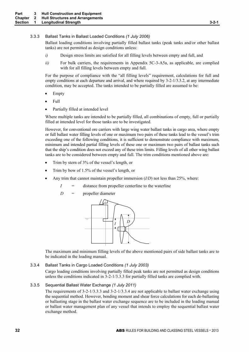
Part 3 Hull Construction and Equipment Chapter 2 Hull Structures and Arrangements Section 1 Longitudinal Strength 3-2-1
32 ABS RULES FOR BUILDING AND CLASSING STEEL VESSELS . 2013
3.3.3 Ballast Tanks in Ballast Loaded Conditions (1 July 2006) Ballast loading conditions involving partially filled ballast tanks (peak tanks and/or other ballast tanks) are not permitted as design conditions unless:
i) Design stress limits are satisfied for all filling levels between empty and full, and
ii) For bulk carriers, the requirements in Appendix 5C-3-A5a, as applicable, are complied with for all filling levels between empty and full.
For the purpose of compliance with the “all filling levels” requirement, calculations for full and empty conditions at each departure and arrival, and where required by 3-2-1/3.3.2, at any intermediate condition, may be accepted. The tanks intended to be partially filled are assumed to be:
• Empty
• Full
• Partially filled at intended level
Where multiple tanks are intended to be partially filled, all combinations of empty, full or partially filled at intended level for those tanks are to be investigated.
However, for conventional ore carriers with large wing water ballast tanks in cargo area, where empty or full ballast water filling levels of one or maximum two pairs of these tanks lead to the vessel’s trim exceeding one of the following conditions, it is sufficient to demonstrate compliance with maximum, minimum and intended partial filling levels of these one or maximum two pairs of ballast tanks such that the ship’s condition does not exceed any of these trim limits. Filling levels of all other wing ballast tanks are to be considered between empty and full. The trim conditions mentioned above are:
• Trim by stern of 3% of the vessel’s length, or
• Trim by bow of 1.5% of the vessel’s length, or
• Any trim that cannot maintain propeller immersion (I/D) not less than 25%, where:
I = distance from propeller centerline to the waterline
D = propeller diameter
I D
The maximum and minimum filling levels of the above mentioned pairs of side ballast tanks are to be indicated in the loading manual.
3.3.4 Ballast Tanks in Cargo Loaded Conditions (1 July 2003) Cargo loading conditions involving partially filled peak tanks are not permitted as design conditions unless the conditions indicated in 3-2-1/3.3.3 for partially filled tanks are complied with.
3.3.5 Sequential Ballast Water Exchange (1 July 2011) The requirements of 3-2-1/3.3.3 and 3-2-1/3.3.4 are not applicable to ballast water exchange using the sequential method. However, bending moment and shear force calculations for each de-ballasting or ballasting stage in the ballast water exchange sequence are to be included in the loading manual or ballast water management plan of any vessel that intends to employ the sequential ballast water exchange method.

Part 3 Hull Construction and Equipment Chapter 2 Hull Structures and Arrangements Section 1 Longitudinal Strength 3-2-1
ABS RULES FOR BUILDING AND CLASSING STEEL VESSELS . 2013 33
3.5 Wave Loads 3.5.1 Wave Bending Moment Amidships
The wave bending moment, expressed in kN-m (tf-m, Ltf-ft), may be obtained from the following equations:
Mws = − k1C1L2B(Cb + 0.7 ) × 10-3 Sagging Moment
Mwh = + k2C1L2BCb × 10-3 Hogging Moment
where
k1 = 110 (11.22, 1.026)
k2 = 190 (19.37, 1.772)
C1 = 10.75 5.1
100300
−
−L 90 ≤ L ≤ 300 m
= 10.75 300 < L < 350 m
= 10.75 5.1
150350
−
−L 350 ≤ L ≤ 500 m
C1 = 10.75 5.1
328984
−
−L 295 ≤ L ≤ 984 ft
= 10.75 984 < L < 1148 ft
= 10.75 5.1
4921148
−
−L 1148 ≤ L ≤ 1640 ft
L = length of vessel, as defined in 3-1-1/3.1, in m (ft)
B = breadth of vessel, as defined in 3-1-1/5, in m (ft)
Cb = block coefficient, as defined in 3-1-1/11.3, but is not to be taken less than 0.6
3.5.2 Envelope Curve of Wave Bending Moment The wave bending moment along the length, L, of the vessel may be obtained by multiplying the midship value by the distribution factor M, given by 3-2-1/Figure 2.
3.5.3 Wave Shear Force The envelopes of maximum shearing forces induced by waves, Fw, as shown in 3-2-1/Figure 3 and 3-2-1/Figure 4, may be obtained from the following equations.
Fwp = + kF1C1L B (Cb + 0.7) × 10-2 For positive shear force
Fwn = − kF2C1L B (Cb + 0.7) × 10-2 For negative shear force
where
Fwp, Fwn = maximum shearing force induced by wave, in kN (tf, Ltf)
C1 = as defined in 3-2-1/3.5.1
L = length of vessel, as defined in 3-1-1/3.1, in m (ft)
B = breadth of vessel, as defined in 3-1-1/5, in m (ft)
Cb = block coefficient, as defined in 3-1-1/11.3, but not to be taken less than 0.6
k = 30 (3.059, 0.2797)
F1 = distribution factor, as shown in 3-2-1/Figure 3
F2 = distribution factor, as shown in 3-2-1/Figure 4

Part 3 Hull Construction and Equipment Chapter 2 Hull Structures and Arrangements Section 1 Longitudinal Strength 3-2-1
34 ABS RULES FOR BUILDING AND CLASSING STEEL VESSELS . 2013
FIGURE 1 Sign Convention
(+)
(+)
FSW, FW
MSW, MW
Aft Fore
FIGURE 2 Distribution Factor M
0
M
Aftend of L
Forwardend of L
0.4 0.65 1.00.0
1.0
Distance from the aft end of L in terms of L

Part 3 Hull Construction and Equipment Chapter 2 Hull Structures and Arrangements Section 1 Longitudinal Strength 3-2-1
ABS RULES FOR BUILDING AND CLASSING STEEL VESSELS . 2013 35
FIGURE 3 Distribution Factor F1
0
Aftend of L
Forwardend of L
0.92 X 190 Cb
110 (Cb + 0.7)
1.0
0.7F1
0.0 0.2 0.3 0.4 0.6 0.7 0.85 1.0
Distance from the aft end of L in terms of L
FIGURE 4 Distribution Factor F2
0
Aftend of L
Forwardend of L
190 Cb
110 (Cb + 0.7)
0.92
F2
Distance from the aft end of L in terms of L
0.7
0.0 0.2 0.3 0.4 0.6 0.7 0.85 1.0

Part 3 Hull Construction and Equipment Chapter 2 Hull Structures and Arrangements Section 1 Longitudinal Strength 3-2-1
36 ABS RULES FOR BUILDING AND CLASSING STEEL VESSELS . 2013
3.7 Bending Strength Standard 3.7.1 Hull Girder Section Modulus
3.7.1(a) Section Modulus. The required hull girder section modulus for 0.4L amidships is to be the greater of the values obtained from the following equation or 3-2-1/3.7.1(b):
SM = Mt / fp cm2-m (in2-ft)
where
Mt = total bending moment, as obtained below
fp = nominal permissible bending stress
= 17.5 kN/cm2 (1.784 tf/cm2, 11.33 Ltf/in2)
The total bending moment, Mt, is to be considered as the maximum algebraic sum (see sign convention in 3-2-1/3.1) of still-water bending moment and wave-induced bending moment, as follows:
Mt = Msw + Mw
where
Msw = still-water bending moment in accordance with 3-2-1/3.3, in kN-m (tf-m, Ltf-ft).
Mw = maximum wave-induced bending moment in accordance with 3-2-1/3.5.1
3.7.1(b) Minimum Section Modulus. The minimum hull girder section modulus amidships is not to be less than obtained from the following equation:
SM = C1C2L2B (Cb + 0.7) cm2-m (in2-ft)
where
C1 = as defined in 3-2-1/3.5
C2 = 0.01 (0.01, 1.44 × 10⁻⁴)
L = length of vessel, as defined in 3-1-1/3.1, in m (ft)
B = breadth of vessel, as defined in 3-1-1/5, in m (ft)
Cb = block coefficient, as defined in 3-1-1/11.3, but is not to be taken less than 0.6
3.7.1(c) Extension of Midship Section Modulus. In general, where the still-water bending moment envelope curve is not submitted or where 3-2-1/3.7.1(b) governs, scantlings of all continuous longitudinal members of the hull girder are to be maintained throughout 0.4L amidships and then may be gradually tapered beyond.
Where the scantlings are based on the still-water bending moment envelope curves, items included in the hull girder section modulus amidships are to be extended as necessary to meet the hull girder section modulus required at the location being considered.
3.7.2 Hull Girder Moment of Inertia The hull girder moment of inertia, I, amidships, is to be not less than:
I = L ⋅ SM/33.3 cm2-m2 (in2-ft2)
where
L = length of vessel, as defined in 3-1-1/3.1, in m (ft)
SM = required hull girder section modulus, in cm2-m (in2-ft). See 3-2-1/3.7.1.

Part 3 Hull Construction and Equipment Chapter 2 Hull Structures and Arrangements Section 1 Longitudinal Strength 3-2-1
ABS RULES FOR BUILDING AND CLASSING STEEL VESSELS . 2013 37
3.7.3 Hull Girder Strength Outside of 0.4L Amidships (1 July 2011) The strength of the hull girder is to be checked at sections outside of 0.4L amidships. The required section modulus for the regions outside 0.4L amidships is to be obtained based on the total bending moment at the section considered and applying the permissible bending stress as given in 3-2-1/3.7.1(a). As a minimum hull girder bending strength checks are to be carried out at the following locations:
• In way of the forward end of the engine room.
• In way of the forward end of the foremost cargo hold.
• At any locations where there are significant changes in the hull cross-section.
• At any locations where there are changes in the framing system.
Continuity of structure is to be maintained throughout the length of the ship. Where significant changes in the structural arrangement occur adequate transitional structure is to be provided.
For ships with large deck openings, such as containerships, sections at or near to the aft and forward quarter length positions are to be checked. For such ships with cargo holds aft of the superstructure, deckhouse or engine room, strength checks of sections in way of the aft end of the aft-most holds, and the aft end of the deckhouse or engine room are to be performed.
Buckling strength of members contributing to longitudinal strength and subjected to compressive and shear stresses is to be checked in accordance with 3-2-1/19, in particular in regions where changes in the framing system or significant changes in the hull cross-section occur.
3.9 Shearing Strength 3.9.1 General
In calculating the nominal total shear stress, fs, due to still-water and wave-induced loads, the maximum algebraic sum of the shearing force in still-water Fsw and that induced by wave Fw at the station examined is to be used. The thickness of the side shell, and where fitted, the longitudinal bulkhead, is to be such that the nominal total shear stress fs, as obtained from 3-2-1/3.9.2 or 3-2-1/3.9.4, are not greater than 11.0 kN/cm2 (1.122 tf/cm2, 7.122 Ltf/in2).
3.9.2 Shearing Strength for Vessels without Effective Longitudinal Bulkheads For vessels without continuous longitudinal bulkheads, the nominal total shear stress fs in the side shell plating may be obtained from the following equation:
fs = (Fsw + Fw) m/2tsI
where
I = moment of inertia of the hull girder at the section under consideration, in cm4 (in4)
m = first moment, in cm3 (in3), about the neutral axis, of the area of the effective longitudinal material between the horizontal level at which the shear stress is being determined and the vertical extremity of effective longitudinal material, taken at the section under consideration.
ts = thickness of the side shell plating at the position under consideration, in cm (in.)
Fsw = hull girder shearing force in still-water, in kN (tf, Ltf)
Fw = Fwp or Fwn, as specified by 3-2-1/3.5.3, in kN (tf, Ltf), depending upon loading
3.9.3 Modification of Hull girder Shearing Force Peaks (1997) The hull girder shearing force in still water, Fsw, to be used for calculating shear stresses in the side shell plating may be modified to account for the loads transmitted through the double bottom structure to the side shell through the transverse bulkhead. For this modification, unless a detailed calculation is performed, the following equation may be used as guidance to determine the shear force carried by the side shell at the transverse bulkhead (see 3-2-1/Figure 5), provided that the girders in the double bottom are arranged in accordance with 5C-3-4/7.1.1 or 5C-4-2/9.1, as appropriate.

Part 3 Hull Construction and Equipment Chapter 2 Hull Structures and Arrangements Section 1 Longitudinal Strength 3-2-1
38 ABS RULES FOR BUILDING AND CLASSING STEEL VESSELS . 2013
Fs = Fsw – FB kN (tf, Ltf) where
Fsw = hull girder shearing force in still water as obtained by the conventional direct integration method, in kN (tf, Ltf).
FB = FBA or FBF , whichever is the lesser
FBA = (0.45 – 0.2A/bA)WAbA/B
FBF = (0.45 – 0.2F/bF)WFbF/B
WA, WF = total load (net weight or net buoyancy) in the hold immediately abaft or forward of the bulkhead in question, in kN (tf, Ltf)
A, F = length of the adjacent holds, respectively, containing WA and WF, in m (ft)
bA, bF = breadth of the double bottom structure in the holds immediately abaft and forward of the bulkhead in question, respectively, in m (ft). For vessels having lower wing tanks with sloping tops, making an angle of about 45 degrees with the horizontal, the breadth may be measured between the midpoints of the sloping plating. For vessels having double skins with flat inner bottom, it may be measured to the inner skins.
B = breadth of vessel, as defined in 3-1-1/5, in m (ft)
3.9.4 Shearing Strength for Vessels with Two or Three Longitudinal Bulkheads For vessels having continuous longitudinal bulkheads, the total shear stresses in the side shell and the longitudinal bulkheads are to be calculated by an acceptable method. In determining the still-water shear force, consideration is to be given to the effects of non-uniform athwartship distribution of loads. The method described in Appendix 3-2-A1 may be used as a guide in calculating the nominal total shear stress fs related to the shear flow in the side shell or longitudinal bulkhead plating.
Alternative methods of calculation will also be considered. Some acceptable methods are shown in 5C-1-4/5 and Appendix 5C-2-A1.
FIGURE 5 Shear Force Distribution (1997)
WF
WA
FSW curve
A F
FBAFBF
FS curve WF
WA
Inner Bottom
Bhd Bhd BhdWeight WA < Weight WF

Part 3 Hull Construction and Equipment Chapter 2 Hull Structures and Arrangements Section 1 Longitudinal Strength 3-2-1
ABS RULES FOR BUILDING AND CLASSING STEEL VESSELS . 2013 39
5 Longitudinal Strength with Higher-Strength Materials
5.1 General Vessels where the effective longitudinal material of either the upper or lower flanges of the main hull girder, or both, are constructed of materials having mechanical properties greater than those of ordinary-strength hull structural steel (see Section 2-1-2), are to have longitudinal strength generally in accordance with the preceding paragraphs of this section, but the value of the hull girder section modulus and permissible shear stress may be modified as permitted by 3-2-1/5.5 and 3-2-1/5.7. Application of higher-strength material is to be continuous over the length of the vessel to locations where the stress levels will be suitable for the adjacent mild-steel structure. Higher-strength steel is to be extended to suitable locations below the strength deck and above the bottom, so that the stress levels will be satisfactory for the remaining mild steel structure. Longitudinal framing members are to be continuous throughout the required extent of higher-strength steel.
5.3 Hull Girder Moment of Inertia (2012) The hull girder moment of inertia is to be not less than required by 3-2-1/3.7.2 using the mild steel section modulus obtained from 3-2-1/3.7.1.
5.5 Hull Girder Section Modulus When either the top or bottom flange of the hull girder, or both, is constructed of higher-strength material, the section modulus, as obtained from 3-2-1/3.7, may be reduced by the factor Q.
SMhts = Q (SM)
where
SM = section modulus as obtained from 3-2-1/3.7
Q = 0.78 for H32 strength steel
Q = 0.72 for H36 strength steel
Q = 0.68 for H40 strength steel
H32, H36, H40 = as specified in Section 2-1-3.
Q factor for steels having other yield points or yield strengths will be specially considered.
5.7 Hull girder Shearing Force Where the side shell or longitudinal bulkhead is constructed of higher strength material, the permissible shear stresses indicated in 3-2-1/3.9 may be increased by the factor 1/Q. For plate panel stability, see 3-2-1/19.
7 Loading Guidance
7.1 Loading Manual and Loading Instrument (1 July 1998) All vessels contracted for construction on or after 1 July 1998, are to be provided with a loading manual and, where required, a loading instrument in accordance with Appendix 3-2-A2.
In addition, bulk carriers, ore carriers and combination carriers 150 m (492 ft) or more in length (Lf) are to comply with the requirements in Appendix 3-2-A3.
7.3 Allowable Stresses (1 July 1998) 7.3.1 At Sea
See 3-2-1/3.7.1 for bending stress and 3-2-1/3.9.1 for shear stress for vessels with ordinary strength steel material. For higher-strength steel, the allowable stress may be increased by a factor of 1/Q where Q is as defined in 3-2-1/5.5.
7.3.2 In Port The allowable still water in-port stress is 13.13 kN/cm2 (1.34 tf/cm2, 8.5 Ltf/in2) for bending and 10 kN/cm2 (1.025 tf/cm2, 6.5 Ltf/in2) for shear. For higher-strength steel, the allowable stress may be increased by a factor of 1/Q where Q is as defined in 3-2-1/5.5.

Part 3 Hull Construction and Equipment Chapter 2 Hull Structures and Arrangements Section 1 Longitudinal Strength 3-2-1
40 ABS RULES FOR BUILDING AND CLASSING STEEL VESSELS . 2013
9 Section Modulus Calculation
9.1 Items Included in the Calculation In general, the following items may be included in the calculation of the hull girder section modulus, provided that they are continuous or effectively developed:
• Deck plating (strength deck and other effective decks)
• Shell and inner bottom plating
• Deck and bottom girders
• Plating and longitudinal stiffeners of longitudinal bulkheads
• All longitudinals of deck, side, bottom and inner bottom
• Continuous longitudinal hatch coamings. See 3-2-1/13.
9.3 Effective Areas Included in the Calculation In general, all openings are to be deducted from the sectional areas of longitudinal strength members to be used in the hull girder section modulus calculation, except that small isolated openings need not be deducted, provided that these openings and the shadow area breadths of other openings in any one transverse section do not reduce the hull girder section modulus by more than 3%. The breadth or depth of such openings is not to be greater than 1200 mm (47 in.) or 25% of the breadth or depth of the member in which it is located, whichever is less, with a maximum of 75 mm (3 in.) for scallops. The length of small isolated openings, which are not required to be deducted, is generally not to be greater than 2500 mm (100 in.). The shadow area of an opening is the area forward and aft of the opening enclosed by lines drawn tangential to the corners of the opening and intersecting each other to form an included angle of 30 degrees. See 3-2-1/Figure 6.
9.5 Section Modulus to the Deck or Bottom The section modulus to the deck, or bottom, is obtained by dividing the moment of inertia I by the distance from the neutral axis to the molded deck line at side or to the base line, respectively.
9.7 Section Modulus to the Top of Hatch Coamings For continuous longitudinal hatch coamings, in accordance with 3-2-1/13, the section modulus to the top of the coaming is to be obtained by dividing the moment of inertia I by the distance from the neutral axis to the deck at side plus the coaming height. This distance need not exceed yt as given by the following equation, provided that yt is not less than the distance to the molded deck line at side.
yt = y(0.9 + 0.2x/B) m (ft)
where y = distance, in m (ft), from the neutral axis to the top of the continuous coaming.
x = distance, in m (ft), at the top of the hatch coaming from the outboard edge of the continuous coaming web plate to the centerline of the vessel
B = breadth of vessel, as defined in 3-1-1/5, in m (ft)
x and y are to be measured to the point giving the largest value of yt
Section modulus to the top of longitudinal hatch coamings between multi-hatchways will be subject to special considerations.

Part 3 Hull Construction and Equipment Chapter 2 Hull Structures and Arrangements Section 1 Longitudinal Strength 3-2-1
ABS RULES FOR BUILDING AND CLASSING STEEL VESSELS . 2013 41
11 Strength Decks
11.1 Definition The uppermost deck to which the side shell plating extends is to be considered the strength deck for that portion of the length, except in way of short superstructures, wherein the modified requirements for the side shell (see 3-2-2/3) and superstructure deck (see 3-2-11/1.3) are adopted. In way of such superstructures, the deck on which the superstructures are located is to be considered the strength deck.
11.3 Tapering of Deck Sectional Areas In general, the tapering of deck sectional areas beyond the amidship 0.4L is to be in accordance with 3-2-1/3.7.1(c). The deck sectional area at 0.15L from the ends may be one-half of the amidships deck area. In way of a superstructure beyond the amidship 0.4L, the strength deck area may be reduced to approximately 70% of the deck area required at that location if there were no superstructure.
13 Continuous Longitudinal Hatch Coamings and Above Deck Girders Where strength deck longitudinal hatch coamings of length greater than 0.14L are effectively supported under by longitudinal bulkheads or deep longitudinal girders, the coamings are to be longitudinally stiffened in accordance with 3-2-15/5.9. The hull girder section modulus amidships to the top of the coamings is to be as required by 3-2-1/3.7.1, 3-2-1/3.7.2 and 3-2-1/9.7, but the section modulus to the deck at side, excluding the coamings, need not be determined in way of such coamings.
Continuous longitudinal girders on top of the strength deck are to be considered similarly. Their scantlings are also to be in accordance with Section 3-2-8.
15 Effective Lower Decks
To be considered effective, and in order to be included in calculating the hull girder section modulus, the thickness of the stringer plate and the deck plating is to comply with the requirements of 3-2-3/5. The sectional areas of lower decks used in calculating the section modulus are to be obtained as described in 3-2-1/9.3, but should exclude the cutout in the stringer plate in way of through frames. In general, where the still-water bending moment envelope curve is not submitted, or where 3-2-1/3.7.1(b) governs, these areas are to be maintained throughout the midship 0.4L and may be gradually reduced to one-half their midship value at 0.15L from the ends. Where bending moment envelope curves are used, the deck sectional areas are to be adequate to meet the hull girder section modulus requirements at the location being considered.
17 Longitudinal Deck Structures Inboard of Lines of Openings
17.1 General Where deck structures are arranged with two or more large openings abreast, the degree of effectiveness of that portion of the longitudinal structure located between the openings is to be determined in accordance with the following:
Plating and stiffening members forming these structures may be included in the hull girder section modulus calculation, provided they are substantially constructed, well supported both vertically and laterally, and developed at their ends to be effectively continuous with other longitudinal structure located forward and abaft that point.

Part 3 Hull Construction and Equipment Chapter 2 Hull Structures and Arrangements Section 1 Longitudinal Strength 3-2-1
42 ABS RULES FOR BUILDING AND CLASSING STEEL VESSELS . 2013
17.3 Effectiveness The plating and longitudinal stiffening members of longitudinal deck structures complying with the basic requirements of the foregoing paragraph, supported by longitudinal bulkheads, in which the transverse slenderness ratio /r is not greater than 60, may be considered as fully effective in the hull girder section modulus. Longitudinal deck structures, not supported by longitudinal bulkheads, but of substantial construction having a slenderness ratio /r about any axis not greater than 60, based on the span between transverse bulkheads, or other major supports, may be considered as partially effective. The effective area, obtained as the product of the net sectional area of the longitudinal deck structure inboard of lines of hatch openings and the factor Ho, as given below, may be used in the hull girder section modulus calculations.
++
=
IAZ
AA
Hoo
o 2
38.01
62.0
where
A = cross sectional area of hull girder amidships, port and starboard, excluding longitudinal deck structures inside the lines of outermost hatch openings, in cm2 (in2)
I = moment of inertia of hull girder amidships, port and starboard, about the horizontal neutral axis, excluding longitudinal deck structures inside the lines of outermost hatch openings, in cm2-m2 (in2-ft2)
Z = distance between the horizontal neutral axis of area A, and the centroid of area Ao , in m (ft)
Ao = total cross sectional area of the longitudinal deck structures inside the lines of outermost hatch openings, including plating, longitudinal stiffeners, and girders, port and starboard, in cm2 (in2)
An efficiency factor obtained by other methods of engineering analysis will be subject to special consideration.
19 Buckling Strength (1995) Where the various strength members are subjected to compressive or shear stresses due to longitudinal bending, the stability of the local plate panels and the supporting members is to be checked against buckling. Calculations, in accordance with Appendix 3-2-A4, are to be submitted for review.
Where still water bending moments are positive (hogging) in all operating conditions, the total bending moment, Mt , is to be taken as not less than 0.9Mws for the purpose of evaluating the structural stability of the hull girder upper flange. Where it can be shown that all possible conditions of loading between lightship and full load draft result in positive (hogging) still water bending moments, such as with passenger vessels, the above specified minimum total bending moment may be specially considered. A statistical analysis of wave induced bending moment is to be carried out in such instances, taking into account the effect of the hull form including bow flare.

Part 3 Hull Construction and Equipment Chapter 2 Hull Structures and Arrangements Section 1 Longitudinal Strength 3-2-1
ABS RULES FOR BUILDING AND CLASSING STEEL VESSELS . 2013 43
FIGURE 6 Effective Area of Hull Girder Members
NON-EFFECTIVE AREA
HORIZONTAL PLAN - DECK
VERTICAL ELEVATION - BOTTOM
30º
30º
30º
15º
15º
44 ABS RULES FOR BUILDING AND CLASSING STEEL VESSELS . 2013
P A R T Appendix 1: Calculation of Shear Stresses for Vessels Having Longitudinal Bulkheads
3 C H A P T E R 2 Hull Structures and Arrangements
A P P E N D I X 1 Calculation of Shear Stresses for Vessels Having Longitudinal Bulkheads
1 Methods of Calculation The nominal total shear stress fs in the side shell or longitudinal bulkhead plating is related to the shear flow N at that point, by the following equation:
fs = N/t, kN/cm2 (tf/cm2, Ltf/in2)
N = shear flow, kN/cm (tf/cm, Ltf/in)
t = thickness of the plating, cm (in.)
3 Calculation of the Shear Flow Around Closed Sections The shear flow of a closed and prismatic structure is expressed by the following equation.
N = (F m/I) + Ni, kN/cm (tf/cm, Ltf/in)
F = total shear force at the section under consideration, in kN (tf, Ltf)
m = first moment about the neutral axis of the section, in cm3 (in3), of the area of the longitudinal material between the zero shear level and the vertical level, at which the shear stress is being calculated
m = ∫ ∑=
+p
o
n
oiii zadstZ cm3 (in3)
I = moment of inertia of the section, in cm4 (in4)
Ni = constant shear flow around the cell regarded as an integration constant of unknown value arising from substituting the statically indeterminate structure by statically determinate one, in kN/cm (tf/cm, Ltf/in)
Z = distance from section neutral axis to a point in the girth, positive downward, in cm (in.)
a = equivalent sectional area of the stiffener or girder attached to the deck, shell and bulkhead plating, in cm2 (in2)
s = length along girth and longitudinal bulkhead, in cm (in.)
5 Calculation of m To calculate the value of m requires the knowledge or assumption of a zero shear point in the closed cell. As an example, in the case of a simplified tanker section, the deck point at the centerline is a known point of zero shear in the absence of the centerline girder. An arbitrary point may be chosen in the wing tank cell. Superposition of the constant Ni to the shear flow resulting from the assumption of zero shear point will yield to the correct shear flow around the wing cell.

Part 3 Hull Construction and Equipment Chapter 2 Hull Structures and Arrangements Appendix 1 Calculation of Shear Stresses for Vessels Having Longitudinal Bulkheads 3-2-A1
ABS RULES FOR BUILDING AND CLASSING STEEL VESSELS . 2013 45
7 Determination of Ni Ni is determined by using Bredt’s torsion formula, making use of the assumption that there is no twist in the cell section, i.e., the twist moment resulting from the shear flow around a closed cell should equal zero,
or 0=∫ tdsN . In a multicell structure of n number of cells, the formula can be written for the ith cell as
follows.
∫∫∫∫ ++= − tdsN
tdsN
tdsm
IF
tdsN iDivii ii 1 01 =+ ∫+ Divi t
dsN
Div = common division between cell i and the adjacent cells i − 1 and i + 1.
The first term represents twist moment around cell i at the assumed statically determined status. The m values are calculated upon arbitrary zero shear points in the cell i and the adjacent cells. The remaining terms in the equations represent the balancing twist moments around cell i and of those carried out by the common divisions in the adjacent cells i − 1 and i + 1.
To determine the constant shear flow in the cells N1, N2, . . . Ni, Nn, n number of similar equations are formed for each cell and are solved simultaneously.

46 ABS RULES FOR BUILDING AND CLASSING STEEL VESSELS . 2013
P A R T A p p e n d i x 2 : L o a d i n g M a n u a l s a n d L o a d i n g I n s t r u m e n t s
3 C H A P T E R 2 Hull Structures and Arrangements
A P P E N D I X 2 Loading Manuals and Loading Instruments (1 July 1998)
Note: These requirements are intended to satisfy Regulation 10(1) of the International Convention on Load Lines, 1966.
1 General
1.1 Application The requirements in this Appendix apply to all classed cargo vessels that are contracted for construction on or after 1 July 1998.
For bulk carriers, ore carriers and combination carriers having a freeboard length (Lf ), as defined in 3-1-1/3.3, of 150 m (492 ft) and above, additional requirements in Appendix 3-2-A3 will also apply.
3 Definitions
3.1 Loading Guidance Loading guidance is a generic term covering both loading manual and loading instrument, as defined below.
3.1.1 Loading Manual A loading manual is a document containing sufficient information to enable the master of the vessel to arrange for the loading and ballasting of the vessel in such a way as to avoid the creation of any unacceptable stresses in the vessel’s structure.
3.1.2 Loading Instrument A loading instrument is an instrument by means of which it can be easily and quickly ascertained that the still-water bending moments, shear forces, and, where applicable, the still-water torsional moments and lateral loads at specified points along the length of the vessel will not exceed the specified values in any load or ballast condition.
3.3 Category I Vessels Category I vessels are any of the following:
3.3.1
Vessels, such as container carriers, with large deck openings where combined stresses due to vertical and horizontal hull girder bending, torsional and lateral loads need be considered
3.3.2
Vessels, such as bulk carriers, ore carriers and combination carriers, designed for non-homogeneous loading, where the cargo and/or ballast may be unevenly distributed, except those belonging to 3-2-A2/3.5.3.

Part 3 Hull Construction and Equipment Chapter 2 Hull Structures and Arrangements Appendix 2 Loading Manuals and Loading Instruments 3-2-A2
ABS RULES FOR BUILDING AND CLASSING STEEL VESSELS . 2013 47
3.3.3
Tank vessels, such as oil carrier and fuel carriers, except those belonging to 3-2-A2/3.5.3.
3.3.4
Chemical carriers and gas carriers
3.5 Category II Vessels Category II vessels are any of the following:
3.5.1
Vessels, such as passenger vessels and others, with such arrangements that would allow only a small possibility for variation in the distribution of cargo and ballast
3.5.2
Vessels, such as ro-ro ferries, on regular and fixed trading patterns where the loading manual gives sufficient guidance
3.5.3
Vessels less than 120 m (394 ft) in length, L, when their design takes into account the uneven distribution of cargo or ballast.
5 Required Loading Guidance
5.1 Loading Manual All vessels are to be provided with a loading manual reviewed and stamped by ABS in accordance with 3-2-A2/7.
5.3 Loading Instrument (2003) In addition to the loading manual, vessels of Category 1 of 100 m (328 ft) or more in length are to be provided with a loading instrument verified in accordance with 3-2-A2/9.
5.5 Modifications Where modifications to the vessel or to the loading/trading pattern result in changes to the input information, a revised or new loading manual is to be submitted and a stamped copy is to be placed aboard the vessel to replace the existing manual. The loading instrument is to be verified in accordance with 3-2-A2/9.3 or newly installed and verified in such cases.
Where changes due to modification of the vessel are such that the still water bending moments and shear forces corresponding to the new loading conditions are within ±2% of the existing allowable values, the existing allowable values need not be modified.
7 Loading Manual
7.1 Required Information The loading manual is to be based on the final data of the vessel and is to include at least the following information:
i) The loading conditions upon which the design of this vessel is approved.
ii) The results of the calculations of still water bending moments and shear forces.
iii) Permissible limits of still water bending moments and shear forces and, where applicable, limitations due to torsional and lateral loads.
iv) Maximum allowable local double bottom loading.

Part 3 Hull Construction and Equipment Chapter 2 Hull Structures and Arrangements Appendix 2 Loading Manuals and Loading Instruments 3-2-A2
48 ABS RULES FOR BUILDING AND CLASSING STEEL VESSELS . 2013
v) If cargoes other than bulk cargoes are contemplated, such cargoes are to be listed together with any specific instructions for loading.
vi) Maximum allowable load on deck and hatch covers. If the vessel is not approved to carry load on deck or hatch covers, that fact is to be clearly stated in the loading manual.
7.3 Loading Conditions The above information is to be based on the intended service conditions. See 3-2-A2/Table 1 for the selection of loading conditions.
7.5 Language The loading manual is to be prepared in, or is to include, a language understood by the user. English may be considered to be a language understood by the user.
9 Loading Instrument
9.1 Type A loading instrument is to be digital. A single point loading instrument is not acceptable.
9.3 Required Verifications Before a loading instrument is accepted for the vessel, all relevant aspects of the instrument, including but not limited to, the following, are to be demonstrated to the Surveyor for his/her personal verification:
• That the instrument is type approved, where applicable
• That the instrument is based on the final data of the vessel
• That the number and position of read-out points are satisfactory
• That the relevant limits for all read-out points are satisfactory
• That the operation of the instrument after installation onboard, in accordance with the approved test conditions has been found satisfactory
• That approved test conditions are available onboard
• That an operational manual, which does not require approval, is available onboard for the instrument
9.5 Language The operation manual and the instrument output are to be prepared in, or are to include, a language understood by the user. English may be considered to be a language understood by the user.
11 Annual Surveys The requirements in 7-3-2/1.1.5 are to be complied with as follows:
At each Annual Survey, it is to be verified that the loading manual is onboard and, where applicable, a loading instrument is to be verified in working order. The operation manual for the loading instrument is also to be verified as being onboard.

Part 3 Hull Construction and Equipment Chapter 2 Hull Structures and Arrangements Appendix 2 Loading Manuals and Loading Instruments 3-2-A2
ABS RULES FOR BUILDING AND CLASSING STEEL VESSELS . 2013 49
TABLE 1 Loading Conditions in the Loading Manual
1. The loading manual is to include at least
1.1 full load conditions, for both departure and arrival conditions,
1.2 ballast conditions, for both departure and arrival conditions (see also 1.5)
1.3 any other critical loading conditions on which the design of the vessel is based.
1.4 in-port conditions (see also 1.5.3)
1.5 Intermediate conditions, including but not limited to
1.5.1 before and after any ballasting/deballasting during the voyage.
1.5.2 ballast exchange and its sequence, where intended,
1.5.3 during loading/unloading (for vessels in 2.1, 2.2 where applicable, and 2.5)
2. The following conditions are to be considered for the particular type of vessel. The list does not preclude any loading conditions that are necessary for the particular service intended:
2.1 Oil Carriers:
2.1.1 homogeneous cargo if consistent with the service of the vessel
2.1.2 cargoes of typical densities within the expected range
2.1.3 part loaded conditions
2.1.4 short voyages (e.g. half bunker)
2.1.5 tank cleaning conditions
2.1.6 docking conditions afloat
2.2 Bulk Carriers, Ore Carriers, Container Carriers, Dry Cargo Vessels, Other Specialized Carriers:
2.2.1 homogeneous cargo if consistent with the service of the vessel
2.2.2 cargoes of typical densities within the expected range
2.2.3 heavy cargo with empty holds or non-homogeneous conditions
2.2.4 short voyages (e.g. half bunker)
2.2.5 deck cargoes
2.2.6 docking conditions afloat
2.3 Liquefied Gas Carriers:
2.3.1 homogeneous loading for all approved cargoes
2.3.2 with empty or partially filled tank(s)
2.3.3 docking conditions afloat
2.4 Chemical Carriers:
2.4.1 conditions for oil carriers
2.4.2 all approved high density cargoes
2.5 Combination Carriers
2.5.1 conditions as specified in 2.1 and 2.2 above.

50 ABS RULES FOR BUILDING AND CLASSING STEEL VESSELS . 2013
P A R T Appendix 3: Loading Manuals and Loading Instruments: Additional Requirements for Bulk Carriers, Ore Carriers and Combination Carriers 150 meters (492 feet) and above in Length (Lf)
3 C H A P T E R 2 Hull Structures and Arrangements
A P P E N D I X 3 Loading Manuals and Loading Instruments: Additional Requirements for Bulk Carriers, Ore Carriers and Combination Carriers 150 meters (492 feet) and above in Length (Lf) (1 July 1998)
1 General
1.1 Application The requirements in this Appendix apply to bulk carriers, ore carriers and combination carriers having a freeboard length (Lf ), as defined in 3-1-1/3.3, of 150 m (492 ft) and above. Unless otherwise stated, these requirements are additional to those in Appendix 3-2-A2.
1.3 Definitions For the purpose of this Appendix, the definitions in 3-2-A2/3 will apply.
3 Required Loading Guidance
3.1 Loading Manual All vessels are to be provided with a Loading Manual, reviewed and stamped by ABS in accordance with 3-2-A3/5.
3.3 Loading Instrument In addition to the loading manual, all vessels of Category I are to be provided with a loading instrument calibrated in accordance with 3-2-A3/7.
3.5 Modifications Where modifications to the vessel or to the loading/trading pattern affect the required information, a revised or new loading manual is to be submitted and a stamped copy is to be placed aboard the vessel, replacing where applicable the invalidated manual. The loading instrument is to be re-calibrated or newly installed and calibrated in such cases.
Where the difference in the calculated still-water bending moments or shear forces is within ±2% of the allowable value, those values may be considered as not being affected.
Part 3 Hull Construction and Equipment Chapter 2 Hull Structures and Arrangements Appendix 3 Loading Manuals and Loading Instruments: Additional Requirements for Bulk Carriers,
Ore Carriers and Combination Carriers L ≥ 150 m (492 ft) 3-2-A3
ABS RULES FOR BUILDING AND CLASSING STEEL VESSELS . 2013 51
5 Loading Manual
5.1 Required Information 5.1.1 Permissible Limits
In addition to 3-2-A2/7.1, the loading manual is to include the following information:
5.1.1(a) For single side skin bulk carriers,
i) The permissible limits of still water bending moments and shear forces in the hold flooded condition in accordance with 5C-3-3/3.1 and 5C-3-A5a/1.
ii) The still water bending moment limits are to be presented in the form of an envelope curve for all combinations of loading conditions and flooded holds.
5.1.1(b) The cargo hold(s) or combination of cargo holds that might be empty at full draft. If it is not permitted to have an empty cargo hold at full draft, this is to be clearly stated in the loading manual.
5.1.1(c) Maximum allowable and minimum required mass of contents of each cargo hold and double bottom space in way thereof, as a function of the draft at the mid length of the hold.
5.1.1(d) (1 July 1999) Maximum allowable and minimum required mass of contents of two cargo holds and double bottom spaces forward and aft of any cargo hold bulkhead, as a function of the mean draft. This mean draft may be taken as the average of the drafts at the mid-length of two holds.
5.1.2 Loading Rate and Sequence 5.1.2(a) The maximum rate of ballast change
5.1.2(b) An instruction that a loading plan is to be agreed with the terminal on the basis of the achievable rates of change of ballast.
5.1.2(c) (2000) Typical sequence of loading from commencement to full deadweight or any contemplated part load conditions. Where applicable, homogeneous conditions and alternate loading conditions are to be included. The typical loading sequences shall be developed with due attention being paid to the loading rate, the deballasting capacity and applicable strength limitations. The Annex to this Appendix and 3-2-A3/Table 2 contain, as guidance only, an example of a Loading Sequence Summary Form and aspects that may be considered in developing the sequence.
5.1.2(d) Typical sequences for change of ballast at sea, where applicable.
5.3 Loading Conditions (2003) The above information is to be based on the intended service conditions. See 3-2-A3/Table 1 for the selection of loading conditions, which replaces 3-2-A2/Table 1 for the vessels covered by this Appendix.
7 Loading Instrument
7.1 Required Verifications In addition to 3-2-A2/9.3, at least the following aspects are to be demonstrated to the Surveyor for his/her verification:
7.1.1 That the instrument can easily and quickly perform calculations to determine that the permissible values at the specified points along the vessel will not be exceeded in any loaded or ballast condition;
7.1.2 That the relevant limits for the mass of contents of each cargo hold and double bottom spaces in way thereof, as a function of the draft at the mid-hold position, are satisfactory;

Part 3 Hull Construction and Equipment Chapter 2 Hull Structures and Arrangements Appendix 3 Loading Manuals and Loading Instruments: Additional Requirements for Bulk Carriers,
Ore Carriers and Combination Carriers L ≥ 150 m (492 ft) 3-2-A3
52 ABS RULES FOR BUILDING AND CLASSING STEEL VESSELS . 2013
7.1.3 (1 July 1999) That the relevant limits for the mass of contents of two cargo holds and double bottom spaces forward and aft of any cargo hold bulkhead, as a function of the mean draft in way of these holds, are satisfactory;
7.1.4 Where applicable for single side skin bulk carriers, that the relevant limits for the still water bending moments and shear forces in any one hold flooded conditions in accordance with 5C-3-3/3.1 and 5C-3-A5a/1 are satisfactory.
TABLE 1 Loading Conditions in the Loading Manual for Bulk Carriers, Ore Carriers and
Combination Carriers 150 Meters (492 Feet) and above in Length (Lf) 1. The loading manual is to include at least the following loading conditions, upon which the design of the vessel is based.
1.1 full load conditions, subdivided into departure and arrival conditions
1.1.1 cargoes of typical densities within the expected range
1.1.2 alternate heavy cargo loading condition (see notes 1 & 5 below)
1.1.3 alternate light cargo loading condition (see notes 2 & 5 below)
1.1.4 homogeneous heavy cargo loading (see notes 3 & 5 below)
1.1.5 homogeneous light cargo loading (see notes 4 & 5 below)
1.1.6 short voyages (e.g. half bunker)
1.1.7 deck cargoes
1.2 multiple port loading/unloading conditions, subdivided into departure and arrival conditions (see note 5 below)
1.3 ballast conditions, subdivided into departure and arrival conditions
1.4 critical loading conditions
1.5 intermediate conditions, including but not limited to
1.5.1 before and after any ballasting/deballasting during the voyage
1.5.2 ballast exchange and its sequence {see 3-2-A3/5.1.2(a), (b) and (d)}
1.6 in-port conditions
1.7 docking conditions afloat
2. The following conditions are to be considered for combination carriers, in addition to the conditions as specified above. The list does not preclude any loading conditions that are necessary for the particular service intended:
2.1 part loaded conditions (see note 5 below)
Notes: 1 Heaviest cargo can be carried and the draft is corresponding to the summer load water line. Loaded holds may not
be filled completely with cargo.
2 Lightest cargo can be carried at the summer load water line. Loaded holds may or may not be filled completely with cargo.
3 (1 July 2003) Heaviest cargo loaded in all cargo holds at the same filling ratio (cargo volume/hold cubic capacity) and at the draft corresponding to the summer load water line. All loaded holds may not be filled up with cargo.
4 Homogeneous loading condition. All cargo holds are filled completely with cargo and the draft is corresponding to the summer load water line.
5 Conditions during loading/unloading are also to be included.

Part 3 Hull Construction and Equipment Chapter 2 Hull Structures and Arrangements Appendix 3 Loading Manuals and Loading Instruments: Additional Requirements for Bulk Carriers,
Ore Carriers and Combination Carriers L ≥ 150 m (492 ft) 3-2-A3
ABS RULES FOR BUILDING AND CLASSING STEEL VESSELS . 2013 53
TABLE 2 Guidance on Loading/Unloading Sequences (2000)
1. In addition to 3-2-A3/5.1.2(c), due attention is to be paid to the following items in the development of typical loading/unloading sequences being submitted for review.
2. The typical sequences are to include, but not limited to, the following:
- alternate hold light and heavy cargo condition
- homogeneous light and heavy cargo condition
- short voyage (full load with less than full fuel)
- multiple port loading/unloading
- deck cargo condition
- block loading
3. The sequences may be port specific if so desired.
4. The sequence should include each and every stage from commencement to full deadweight or vise versa. Whenever the loading/unloading equipment moves to the next location, it constitutes the end of that stage. For each stage, longitudinal as well as local strength of double bottom are to be considered.
5. for each stage, a summary highlighting the essential information such as the following is to be prepared:
- the amount of cargo loaded/unloaded during that stage
- the amount of ballast discharged/ballasted during that stage
- the still-water bending moment and shearing forces at the end of the stage
- trim and draft at the end of the stage

Part 3 Hull Construction and Equipment Chapter 2 Hull Structures and Arrangements Appendix 3 Loading Manuals and Loading Instruments: Additional Requirements for Bulk Carriers,
Ore Carriers and Combination Carriers L ≥ 150 m (492 ft) 3-2-A3
54 ABS RULES FOR BUILDING AND CLASSING STEEL VESSELS . 2013
AN
NEX
G
uida
nce
on L
oadi
ng S
umm
ary
Sequ
ence
For
m [s
ee 3
-2-A
3/5.
1.2(
c)]

ABS RULES FOR BUILDING AND CLASSING STEEL VESSELS . 2013 55
P A R T A p p e n d i x 4 : B u c k l i n g S t r e n g t h o f L o n g i t u d i n a l S t r e n g t h M e m b e r s
3 C H A P T E R 2 Hull Structures and Arrangements
A P P E N D I X 4 Buckling Strength of Longitudinal Strength Members (1995)
1 Application These requirements apply to plate panels and longitudinals subject to hull girder bending and shear stresses.
3 Elastic Buckling Stresses
3.1 Elastic Buckling of Plates 3.1.1 Compression
The ideal elastic buckling stress is given by:
σE = 0.9mE
stb 2
N/mm2 (kgf/mm2, psi)
For plating with longitudinal stiffeners (parallel to compressive stress):
m = 1.1
8.4+Ψ
for (0 ≤ Ψ ≤ 1)
For plating with transverse stiffeners (perpendicular to compressive stress):
m = c 1.1
2.1122
+Ψ
+
s for (0 ≤ Ψ ≤ 1)
where
E = 2.06 × 10⁵ N/mm2 (21,000 kgf/mm2, 30 × 106 psi)
tb = net thickness of plating, in mm (in.), after making standard deductions as given in 3-2-A4/Table 1
s = shorter side of plate panel, in mm (in.)
= longer side of plate panel, in mm (in.)
c = 1.3 when plating stiffened by floors or deep girders
= 1.21 when stiffeners are angles or T-sections
= 1.10 when stiffeners are bulb flats
= 1.05 when stiffeners are flat bars
Ψ = ratio of smallest to largest compressive stress, σa (see 3-2-A4/7.1), varying linearly across panel.

Part 3 Hull Construction and Equipment Chapter 2 Hull Structures and Arrangements Appendix 4 Buckling Strength of Longitudinal Strength Members 3-2-A4
56 ABS RULES FOR BUILDING AND CLASSING STEEL VESSELS . 2013
3.1.2 Shear The ideal elastic buckling stress is given by:
τE = 0.9kt E
stb 2
N/mm2 (kgf/mm2, psi)
where
kt = 5.34 + 4
s 2
E, tb, s and are as defined in 3-2-A4/3.1.1.
3.3 Elastic Buckling of Longitudinals 3.3.1 Column Buckling without Rotation of the Cross Section
For the column buckling mode (perpendicular to plane of plating), the ideal elastic buckling stress is given by:
σE = 2
1 AcEI a N/mm2 (kgf/mm2, psi)
where
Ia = moment of inertia, in cm4 (in4), of longitudinal, including plate flange and calculated with thickness, as specified in 3-2-A4/3.1.1
A = cross-sectional area, in cm2 (in2), of longitudinal, including plate flange and calculated with thickness, as specified in 3-2-A4/3.1.1
= span, in m (ft), of longitudinal
c1 = 1000 (1000, 14.4)
E = as defined in 3-2-A4/3.1.1
3.3.2 Torsional Buckling Mode The ideal elastic buckling stress for the torsional mode is given by:
σE = +
+ 2
22
1
2
10 mKm
IcEI
p
w
π0.385E
p
t
II
N/mm2 (kgf/mm2, psi)
where
K = wEI
Cc 4
4
2 π
m = number of half waves given by 3-2-A4/Table 2
E = as defined in 3-2-A4/3.1.1
c2 = 106 (106, 20736)
It = St. Venant’s moment of inertia, in cm4 (in4), of profile (without plate flange)
= 3
3
3wwth
c for flat bars (slabs)
=
−+
f
fffww b
ttbthc 0.631
31 33
3 for flanged profiles

Part 3 Hull Construction and Equipment Chapter 2 Hull Structures and Arrangements Appendix 4 Buckling Strength of Longitudinal Strength Members 3-2-A4
ABS RULES FOR BUILDING AND CLASSING STEEL VESSELS . 2013 57
c3 = 10-4 (10-4, 1.0)
Ip = polar moment of inertia, in cm4 (in4), of profile about connection of stiffener to plate
= 3
3
3wwth
c for flat bars (slabs)
=
+ ffw
ww tbhth
c 23
3 3 for flanged profiles
Iw = warping constant, in cm6 (in6), of profile about connection of stiffener to plate
= 36
33
4wwth
c for flat bars (slabs)
=
12
23
4wff hbt
c for “Tee” profiles
= ( )2
23
4 12 wf
wf
hb
hbc
+[tf ( bf
2 + 2bf hw + 4hw2) + 3twbf hw] for angles and bulb
profiles
c4 = 10-6 (10-6, 1.0)
hw = web height, in mm (in.)
tw = web thickness, in mm (in.), after making standard deductions, as specified in 3-2-A4/3.1.1
bf = flange width, in mm (in.)
tf = flange thickness, in mm (in.), after making standard deductions, as specified in 3-2-A4/3.1.1. For bulb profiles the mean thickness of the bulb may be used.
= span of profile, in m (ft)
s = spacing of profiles, in mm (in.)
C = spring stiffness exerted by supporting plate panel
=
+ 3
3
3
1.3313
w
pwp
pp
st
thks
tEkN (kgf, lbf)
kp = 1−ηp, not to be taken less than zero
tp = plate thickness, in mm (in.), after making standard deductions, as specified in 3-2-A4/3.1.1
ηp = Ep
a
σσ
σa = calculated compressive stress. For longitudinals, see 3-2-A4/7.1
σEp = elastic buckling stress of supporting plate, as calculated in 3-2-A4/3.1
For flanged profiles, kp need not be taken less than 0.1.

Part 3 Hull Construction and Equipment Chapter 2 Hull Structures and Arrangements Appendix 4 Buckling Strength of Longitudinal Strength Members 3-2-A4
58 ABS RULES FOR BUILDING AND CLASSING STEEL VESSELS . 2013
3.3.3 Web and Flange Buckling For web plate of longitudinals the ideal buckling stress is given by:
σE = 3.8E2
w
w
ht
N/mm2 (kgf/mm2, psi)
For flanges on angles and T-sections of longitudinals, the following requirements will apply:
15≤f
f
tb
bf = flange width, in mm (in.), for angles, half the flange width for T-sections.
tf = as built flange thickness, in mm (in.)
TABLE 1 Standard Deduction
Structure Standard Deduction
Limit Values min.-max. in mm (in.)
— Compartments carrying dry bulk cargoes 0.05t 0.5–1.0 — One side exposure to ballast and/or liquid cargo
Vertical surfaces and surfaces sloped at an angle greater than 25° to the horizontal line
(0.02–0.04)
— One side exposure to ballast and/or liquid cargo Horizontal surfaces and surfaces sloped at an angle less than 25° to the horizontal line
0.10t 2.0–3.0 (0.08–0.12)
— Two side exposure to ballast and/or liquid cargo Vertical surfaces and surfaces sloped at an angle greater than 25° to the horizontal line
— Two side exposure to ballast and/or liquid cargo Horizontal surfaces and surfaces sloped at an angle less than 25° to the horizontal line
0.15t 2.0–4.0 (0.08–0.16)
TABLE 2 Number of Half Waves
0 < K ≤ 4 4 < K ≤ 36 36 < K ≤ 144 144 < K ≤ 400 (m − 1)2 m2 < K ≤ m2 (m + 1) 2 m 1 2 3 4 m
5 Critical Buckling Stresses
5.1 Compression The critical buckling stress in compression, σc, is determined as follows:
σc = σE when σE ≤ 2Fσ
= σF
−
E
F
σσ4
1 when σE > 2Fσ

Part 3 Hull Construction and Equipment Chapter 2 Hull Structures and Arrangements Appendix 4 Buckling Strength of Longitudinal Strength Members 3-2-A4
ABS RULES FOR BUILDING AND CLASSING STEEL VESSELS . 2013 59
where
σF = yield stress of material, in N/mm2 (kgf/mm2, psi). σF may be taken as 235 N/mm2 (24 kgf/mm2, 34,000 psi) for mild steel.
σE = ideal elastic buckling stress calculated according to 3-2-A4/3
5.3 Shear The critical buckling stress in shear, τc, is determined as follows:
τc = τE when τE ≤ 2Fτ
= τF
−
E
F
ττ4
1 when τE > 2Fτ
where
τF = 3Fσ
σF = as given in 3-2-A4/5.1
τE = ideal elastic buckling stress in shear calculated according to 3-2-A4/3.1.2
7 Working Stress
7.1 Longitudinal Compressive Stress The compressive stresses are given in the following formula:
σa = c5 yI
MM
n
sww + N/mm2 (kgf/mm2, psi)
= minimum 30/Q N/mm2 (3.1/Q kgf/mm2, 4400/Q psi)
where
Msw = still water bending moment, as given in 3-2-1/3.7.1(a), in kN-m (tf-m, Ltf-ft)
Mw = wave bending moment, as given in 3-2-1/3.7.1(a), in kN-m (tf-m, Ltf-ft)
In = moment of inertia, in cm4 (in4), of the hull girder
y = vertical distance, in m (ft), from the neutral axis to the considered point
Q = as defined in 3-2-1/5.5 (1.0 for ordinary strength steel)
c5 = 105 (105, 322,560)
Mw and Msw are to be taken as sagging or hogging bending moments, respectively, for members above or below the neutral axis.
7.3 Shear Stresses 7.3.1 Vessels without Effective Longitudinal Bulkheads
The working shear stress, τa, in the side shell of vessels without effective longitudinal bulkheads is given by the following formula:
τa = c6 ( )
ItmFF
s
swsw
2+
N/mm2 (kgf/mm2, psi)

Part 3 Hull Construction and Equipment Chapter 2 Hull Structures and Arrangements Appendix 4 Buckling Strength of Longitudinal Strength Members 3-2-A4
60 ABS RULES FOR BUILDING AND CLASSING STEEL VESSELS . 2013
where
I = moment of inertia of the hull girder section, in cm4 (in4), at the section under consideration.
ms = first moment, in cm3 (in3), about the neutral axis of the area of the effective longitudinal material between the horizontal level at which the shear stress is being determined and the vertical extremity of effective longitudinal material, taken at the position under consideration.
ts = thickness of the side shell plating, in cm (in.), at the position under consideration.
Fsw = hull girder shearing force in still water, in kN (tf, Ltf). See 3-2-1/3.3.
Fw = Fwp or Fwn, in kN (tf, Ltf), as specified by 3-2-1/3.5.3, depending upon loading
c6 = 10 (10, 2240)
7.3.2 Vessels with Two or More Effective Longitudinal Bulkheads The working shear stress, τa, in the side shell or longitudinal bulkhead plating is to be calculated by an acceptable method and in accordance with 3-2-1/3.9.4.
9 Scantling Criteria
9.1 Buckling Stress The design buckling stress, σc, of plate panels and longitudinals (as calculated in 3-2-A4/5.1) is to be such that:
σc ≥ βσa
where
β = 1 for plating and for web plating of stiffeners (local buckling)
= 1.1 for stiffeners
The critical buckling stress, τc, of plate panels (as calculated in 3-2-A4/5.3) is to be such that:
τc ≥ τa
where
τa = working shear stress in the plate panel under consideration, in N/mm2 (kgf/mm2, lbf/in2), as determined by 3-2-A4/7.3.

ABS RULES FOR BUILDING AND CLASSING STEEL VESSELS . 2013 61
P A R T S e c t i o n 2 : S h e l l P l a t i n g
3 C H A P T E R 2 Hull Structures and Arrangements
S E C T I O N 2 Shell Plating
1 Application Shell plating is to be of not less thickness than is required for purposes of longitudinal hull girder strength; nor is it to be less than is required by this section. In general, the shell plating is not to be less in thickness than required by 3-2-10/3.1 for deep tanks. For bottom shell plating bounding tanks having normal tank/air vent configurations in order to avoid accidental overpressure, the head “h” need not be greater than the distance from the plate under consideration to the deck at side. In the case of unusual configurations, or where the tanks are intended to carry liquids having a specific gravity equal to or greater than 1.05, “h” should be in accordance with 3-2-10/3.1.
3 Shell Plating Amidships
3.1 Vessels with No Partial Superstructures Above Uppermost Continuous Deck In vessels that have no partial superstructures above the uppermost continuous deck, the thickness of the bottom and side plating is to be obtained from the appropriate equations where Ds is the molded depth, in m (ft), measured to the uppermost continuous deck.
3.3 Superstructures Fitted Above Uppermost Continuous Deck (Side Plating Extended) Where superstructures are fitted above the uppermost continuous deck to which the side plating extends throughout the amidship 0.4L, the thickness of the bottom and side plating is to be obtained from the appropriate equations where Ds is the molded depth, in m (ft), measured to the superstructure deck. In such cases, the sheer strake beyond the superstructure is to be proportioned from the thickness as required for the sheer strake amidships, where Ds is measured to the uppermost continuous deck.
3.5 Superstructures Fitted Above Uppermost Continuous Deck (Side Plating Not Extended) Where superstructures are fitted above the uppermost continuous deck, to which the side plating does not extend throughout the amidship 0.4L, the thickness of the bottom and side plating is to be obtained from the appropriate equations where Ds is the molded depth, in m (ft), measured to the uppermost continuous deck.
3.7 In Way of Comparatively Short Superstructures In way of comparatively short superstructure decks, or where the superstructure deck is not designed as the strength deck, the thickness of the bottom and side plating is to be obtained from the appropriate equations where Ds is the molded depth, in m (ft), measured to the uppermost continuous deck. In such cases, the thickness of the side plating above the uppermost continuous deck is to be specially considered, but in no case is the thickness to be less than that obtained from equations 1a and 1b in 3-2-3/Table 2, but substituting the frame spacing, in mm (in.), for sb in lieu of the deck beam spacing.

Part 3 Hull Construction and Equipment Chapter 2 Hull Structures and Arrangements Section 2 Shell Plating 3-2-2
62 ABS RULES FOR BUILDING AND CLASSING STEEL VESSELS . 2013
3.9 Side Shell Plating The minimum thickness, t, of the side shell plating throughout the amidship 0.4L, for vessels having lengths not exceeding 427 m (1400 ft), is to be obtained from the following equations:
t = ( s/645 ) )/)(15.2( sDdL − + 2.5 mm for L ≤ 305 m
t = ( s/828 ) )/)(175( sDdL + + 2.5 mm for 305 < L ≤ 427 m
t = ( s/1170 ) )/)(50( sDdL − + 0.1 in. for L ≤ 1000 ft
t = ( s/1500 ) )/)(574( sDdL + + 0.1 in. for 1000 < L ≤ 1400 ft
where
s = spacing of transverse frames or longitudinals, in mm (in.)
L = length of vessel, as defined in 3-1-1/3.1, in m (ft)
d = molded draft, as defined in 3-1-1/9, in m (ft)
Ds = molded depth, in m (ft), as defined in 3-2-2/3.1 through 3-2-2/3.7
The actual ratio of d/Ds is to be used in the above equations, except that the ratio is not to be taken less than 0.0433 L/Ds.
The side shell thickness amidships is to be not less than the thickness obtained by 3-2-2/5.1 using 610 mm (24 in.) as the frame spacing.
3.11 Sheer Strake The minimum width, b, of the sheer strake throughout the amidship 0.4L is to be obtained from the following equations:
b = 5L + 800 mm for L < 200 m
b = 1800 mm for 200 ≤ L ≤ 427 m
b = 0.06L + 31.5 in. for L < 656 ft
b = 71 in. for 656 ≤ L ≤ 1400 ft
where
L = length of vessel, as defined in 3-1-1/3.1, in m (ft)
b = width of sheer strake, in mm (in.)
In general, the thickness of the sheer strake is not to be less than the thickness of the adjacent side shell plating, nor is it to be less than required by equation 1b or 2b in 3-2-3/Table 2, as appropriate, from Decks-A of 3-2-3/Table 1. The thickness of the sheer strake is to be increased 25% in way of breaks of superstructures, but this increase need not exceed 6.5 mm (0.25 in.). Where breaks in way of the forecastle or poop are appreciably beyond the amidship 0.5L, this requirement may be modified.
The top edge of the sheer strake is to be smooth and free of notches. Fittings and bulwarks are not to be welded to the top of the sheer strake within the amidships 0.8L, nor in way of superstructure breaks throughout.
3.13 Bottom Shell Plating Amidships 3.13.1 Extent of Bottom Plating Amidships
The term “bottom plating amidships” refers to the bottom shell plating from the keel to the upper turn of the bilge, extending over the amidships 0.4L.

Part 3 Hull Construction and Equipment Chapter 2 Hull Structures and Arrangements Section 2 Shell Plating 3-2-2
ABS RULES FOR BUILDING AND CLASSING STEEL VESSELS . 2013 63
3.13.2 Bottom Shell Plating The thickness, t, of the bottom plating amidships is not to be less than obtained from the following equations or the thickness determined by 3-2-2/3.17, whichever is greater.
3.13.2(a) For Vessels with Transversely-framed Bottoms
t = (s/519) )/)(19.8 sDdL − + 2.5 mm for L ≤ 183 m
t = (s/940) )/)(65( sDdL − + 0.1 in. for L ≤ 600 ft
3.13.2(b) For Vessels with Longitudinally-framed Bottoms
t = (s/671) )/)(18.3( sDdL − + 2.5 mm for L ≤ 122 m
t = (s/508) )/)(62.5( sDdL − + 2.5 mm for 122 ≤ L ≤ 305 m
t = (s/661) )/)(105( sDdL + + 2.5 mm for 305 < L ≤ 427 m
t = (s/1215) )/)(60( sDdL − + 0.1 in. for L < 400 ft
t = (s/920) )/)(205( sDdL − + 0.1 in. for 400 ≤ L ≤ 1000 ft
t = (s/1197) )/)(344.5( sDdL + + 0.1 in. for 1000 < L ≤ 1400 ft
where L, d, s, and Ds are as defined in 3-2-2/3.9.
The actual ratio of d/Ds is to be used in the above equations, but the ratio is not to be taken less than 0.0433 L/Ds.
After all corrections have been made, the bottom shell thickness amidships is not to be less than the thickness obtained by 3-2-2/5.1 using 610 mm (24 in.) as the frame spacing.
Where the actual bottom hull girder section modulus SMA is greater than required by 3-2-1/3.7.1, and still-water bending moment calculations are submitted, the thickness of the bottom shell may be obtained from the above equations multiplied by the factor Rn defined as follows:
Rn = 1)/1)(/(
1+− ARtp SMSMf σ
but is not to be taken less than 0.85 (d/Ds ≥ 0.65)
= 1.0 (d/Ds ≤ 0.0433L/Ds)
= by linear interpolation (0.0433L/Ds < d/Ds < 0.65)
where
fp = nominal permissible bending stress, in kN/cm2 (tf/cm2, Ltf/in2), as given in 3-2-1/3.7.1
σt = KPt (s/t)2, in kN/cm2 (tf/cm2, Ltf/in2)
K = 0.5 for transverse framing and 0.34 for longitudinal framing
Pt = (0.638H + d)a kN/cm2 (tf/cm2, Ltf/in2)
a = 1.005 × 10⁻³ (1.025 × 10⁻⁴, 1.984 × 10⁻⁴)
SMR = hull girder section modulus required by 3-2-1/3.7.1, in cm2-m (in2-ft)
SMA = bottom hull girder section modulus, in cm2-m (in2-ft), of the vessel with the greater of the bottom shell plating thickness obtained when applying Rn or Rb

Part 3 Hull Construction and Equipment Chapter 2 Hull Structures and Arrangements Section 2 Shell Plating 3-2-2
64 ABS RULES FOR BUILDING AND CLASSING STEEL VESSELS . 2013
t = bottom shell plating thickness required by 3-2-2/3.13.2(a) or 3-2-2/3.13.2(b), in mm (in.)
H = wave parameter, in m (ft)
= 0.0172L + 3.653 m 90 ≤ L ≤ 150 m
= 0.0181L + 3.516 m 150 < L ≤ 220 m
= [4.50L − 0.0071L2+ 103]10-2 m 220 < L ≤ 305 m
= 8.151 m 305 < L ≤ 427 m
= 0.0172L + 11.98 ft 295 < L ≤ 490 ft
= 0.0181L + 11.535 ft 490 ≤ L ≤ 720 ft
= [4.50L − 0.00216L2 + 335]10-2 ft 720 < L ≤ 1000 ft
= 26.750 ft 1000 < L ≤ 1400 ft
L, d and Ds are as defined in 3-2-2/3.9.
Rb is defined in 3-2-2/3.17.2.
SMR/SMA is not to be taken as less than 0.70
Special consideration will be given to vessels constructed of higher-strength steel.
3.15 Flat Plate Keel (1997) The thickness of the flat plate keel is to be 1.5 mm (0.06 in.) greater than that required for the bottom shell plating at the location under consideration. This 1.5 mm (0.06 in.) increase in thickness is not required where the submitted docking plan specifies that all docking blocks are to be arranged clear of the flat plate keel. See 3-1-2/11 and 3-2-2/7.
3.17 Minimum Thickness After all other requirements are met, the thickness, tmin, of the shell plating amidships below the upper turn of bilge is not to be less than obtained from the following equations:
3.17.1 Transverse Framing tmin = s(L + 45.73)/(25L + 6082) mm for L ≤ 183 m
tmin = s(L + 150)/(25L + 19950) in. for L ≤ 600 ft
where
s = frame spacing, in mm (in.), but is not to be less than that given in 3-2-5/1.7
L = length of vessel, as defined in 3-1-1/3.1, in m (ft)
3.17.2 Longitudinal Framing tmin = s(L – 18.3)/(42L + 1070) mm for L ≤ 427 m
tmin = s(L − 60)/(42L + 3510) in. for L ≤ 1400 ft
where
s = frame spacing, in mm (in.), but is not to be less than 88% of that given in 3-2-5/1.7 or 813 mm (32 in.), whichever is less
L = length of vessel, as defined in 3-1-1/3.1, in m (ft)
Where the bottom hull girder section modulus SMA is greater than required by 3-2-1/3.7.1, and still-water bending moment calculations are submitted, the thickness of bottom shell plating amidships, obtained from the above equations, may be multiplied by the factor, Rb.

Part 3 Hull Construction and Equipment Chapter 2 Hull Structures and Arrangements Section 2 Shell Plating 3-2-2
ABS RULES FOR BUILDING AND CLASSING STEEL VESSELS . 2013 65
Rb = AR SMSM / but is not to be taken less than 0.85 (d/Ds ≥ 0.65)
= 1.0 (d/Ds ≤ 0.0433L/Ds)
= by linear interpolation (0.0433L/Ds < d/Ds < 0.65)
where SMR and SMA are as defined in 3-2-2/3.13.2.
For transverse framing, Rb is to be not less than 1.2285 − L/533.55 for SI or MKS units (1.2285 − L/1750 for US units), where L is as defined above, but is not to be taken as less than 122 m (400 ft).
Special consideration will be given to vessels constructed of higher-strength steel.
5 Shell Plating at Ends
5.1 Minimum Shell Plating Thickness The minimum shell plating thickness t at the ends is to be obtained from the following equations and is not to extend for more than 0.1L at the ends. Between the amidship 0.4L and the end 0.1L, the thickness of the plating may be gradually tapered.
t = 0.035 (L + 29) + 0.009 s mm for 90 ≤ L ≤ 305 m
t = (11.70 + 0.009s) 35/D mm for 305 < L ≤ 427 m
t = 0.00042(L + 95) + 0.009s in. for 295 ≤ L ≤ 1000 ft
t = (0.46 + 0.009s) 114.8/D in. for 1000 < L ≤ 1400 ft
where
s = fore or aft peak frame spacing, in mm (in.)
L = length of vessel, as defined in 3-1-1/3.1, in m (ft)
D = molded depth, in m (ft), as defined in 3-1-1/7.1 or 35 m (114.8 ft), whichever is greater
Where the strength deck at the ends is above the freeboard deck, the thickness of the side plating above the freeboard deck may be reduced to the thickness given for forecastle and poop sides at the forward and after ends respectively.
5.3 Immersed Bow Plating The thickness t of the plating below the load waterline forward of 0.16L from the stem is not to be less than is given by the following equation, but need not be greater than the thickness of the side shell plating amidships.
t = 0.05(L + 20) + 0.009s mm for 90 ≤ L ≤ 305 m
t = (16.25 + 0.009s) 35/D mm for 305 < L ≤ 427 m
t = 0.0006(L + 66) + 0.009s in. for 295 ≤ L ≤ 1000 ft
t = (0.64 + 0.009s) 114.8/D in. for 1000 < L ≤ 1400 ft
where
s = fore peak frame spacing, in mm (in.)
L = length of vessel, as defined in 3-1-1/3.1, in m (ft)
D = molded depth, in m (ft), as defined in 3-1-1/7.1 or 35 m (114.8 ft), whichever is greater

Part 3 Hull Construction and Equipment Chapter 2 Hull Structures and Arrangements Section 2 Shell Plating 3-2-2
66 ABS RULES FOR BUILDING AND CLASSING STEEL VESSELS . 2013
5.5 Bottom Forward Where the forward draft of the vessel in the ballast loading condition to be used while the vessel is in heavy weather (heavy ballast draft forward) is less than 0.04L m (ft), the plating on the flat of bottom forward, forward of the location given in 3-2-4/Table 1 is to be not less than required by the following equation:
t = 0.0046s ( ) ff ddL /3.1005.0 221 − mm
t = 0.0026s ( ) ff ddL /3.1005.0 221 − in.
where
s = frame spacing, in mm (in.)
L1 = length of vessel, as defined in 3-1-1/3.1, in m (ft), but need not be taken greater than 214 m (702 ft)
L = length of vessel, as defined in 3-1-1/3.1, in m (ft)
df = heavy ballast draft at the forward perpendicular, in m (ft)
= df × 214/L m (df × 702/L ft), where L > 214 m (702 ft)
The required thickness of the flat of bottom forward plating is also to be in accordance with the requirements given by 3-2-2/3.13, 3-2-2/5.1 and 3-2-2/5.3, as appropriate.
5.7 Forecastle Side Plating The thickness, t, of the plating is to be not less than obtained from the following equations.
t = 0.05(L + 76) + 0.006(s − S) mm L < 106.5 m
t = 0.035(L + 154) + 0.006(s − S) mm L ≥ 106.5 m
t = 0.0006(L + 250) + 0.006(s − S) in. L < 350 ft
t = 0.00042(L + 505) + 0.006(s − S) in. L ≥ 350 ft
where
s = spacing of longitudinal or transverse frames, in mm (in.)
S = standard frame spacing, in mm (in.), given by the equation in 3-2-5/1.7 with an upper limit of 1070 mm (42.5 in.), except that in way of the fore peak, the standard frame spacing is not to exceed 610 mm (24 in.)
L = length of vessel, as defined in 3-1-1/3.1, in m (ft), but need not be taken more than 305 m (1000 ft.)
5.9 Poop Side Plating The thickness, t, of the plating is to be not less than obtained from the following equation:
t = 0.0315(L + 150) + 0.006(s − S) mm. L ≥ 90 m
t = 0.00038(L + 493) + 0.006(s − S) in. L ≥ 295 ft
where
s = spacing of longitudinal or transverse frames, in mm (in.)
S = standard frame spacing, in mm (in.), given by the equation in 3-2-5/1.7 with an upper limit of 1070 mm (42.5 in.), except that in way of the aft peak, the standard frame spacing is not to exceed 610 mm (24 in.)
L = length of vessel, as defined in 3-1-1/3.1, in m (ft), but need not be taken more than 305 m (1000 ft)

Part 3 Hull Construction and Equipment Chapter 2 Hull Structures and Arrangements Section 2 Shell Plating 3-2-2
ABS RULES FOR BUILDING AND CLASSING STEEL VESSELS . 2013 67
5.11 Bow and Stern Thruster Tunnels The thickness of the tunnel plating is not to be less than required by 3-2-2/5.1, where s is to be taken as the standard frame spacing given by the equation in 3-2-5/1.7, nor is the thickness to be less than obtained from the following equation:
t = 0.008d + 3.3 mm
t = 0.008d + 0.13 in.
where
d = inside diameter of the tunnel, in mm (in.), or 968 mm (38 in.), whichever is greater
Where the outboard ends of the tunnel are provided with bars or grids, the bars or grids are to be effectively secured.
5.13 Special Heavy Plates Special heavy plates of the thickness, t, given in the following equations, are to be introduced at the attachments to the stern frame for heel and boss plates, and in way of spectacle bossing. Heavy plates may also be required to provide increased lateral support in the vicinity of the stern tube in vessels of fine form and high power. Thick or double plating is to be fitted around hawse pipes, of sufficient breadth to prevent damage from the flukes of stockless anchors.
5.13.1 Spectacle Bossing t = 0.088(L − 23) + 0.009s mm for 90 < L ≤ 427 m
t = 0.00106(L − 75) + 0.009s in. for 295 < L ≤ 1400 ft
where
L = length of vessel, as defined in 3-1-1/3.1, in m (ft)
s = frame spacing, in mm (in.)
5.13.2 Other Plates on Stern Frame t = 0.094(L − 16) + 0.009s mm for 90 < L ≤ 427 m
t = 0.00113(L − 53) + 0.009s in. for 295 < L ≤ 1400 ft
where
L = length of vessel, as defined in 3-1-1/3.1, in m (ft)
s = frame spacing, in mm (in.)
5.13.3 Boss and Heel Plates The thickness of the boss and heel plating is to be at least 20% greater than the thickness of spectacle bossing obtained in 3-2-2/5.13.1.
7 Bottom Shell Plating for Special Docking Arrangement (1997) Where it is not intended to use keel blocks when drydocking the vessel, the increase to the keel plate thickness in 3-2-2/3.15 will not be required. However, the thickness of the bottom shell plating strakes in way of the docking blocks to be used in lieu of keel blocks when drydocking the vessel is to be increased by 1.5 mm (0.06 in.). In such instances, the recommended docking arrangement is to be indicated on the structural plans submitted for approval and also on the docking plan to be furnished to the vessel.

Part 3 Hull Construction and Equipment Chapter 2 Hull Structures and Arrangements Section 2 Shell Plating 3-2-2
68 ABS RULES FOR BUILDING AND CLASSING STEEL VESSELS . 2013
9 Compensation Compensation is to be made where necessary for openings in the shell. All openings are to have well-rounded corners. Those for cargo, gangway, fueling ports, etc. are to be kept well clear of discontinuities in the hull girder. Local provision is to be made to maintain the longitudinal and transverse strength of the hull. Where it is proposed to fit port-lights in the shell plating, the locations and sizes are to be clearly indicated on the midship-section drawing when first submitted for approval.
11 Breaks Vessels having partial superstructures are to be specially strengthened in way of breaks to limit the local increase in stresses at these locations. The stringer plate thickness and the sheer strake thickness at the lower level is to be doubled or increased in thickness well beyond the break in both directions. The thickness increase is to be 25% in way of breaks in the superstructures, but the increase need not exceed 6.5 mm (0.25 in.). The side plating of the superstructure is to be increased in thickness in way of the break. The side shell plating below the sheer strake and in way of the break is to be increased appropriately and is to extend well beyond the end of the superstructure in such a fashion as to provide a long gradual taper. Where the breaks of the forecastle or poop are appreciably beyond the amidship 0.5L, these requirements may be modified. Gangways, large freeing ports and other openings in the shell or bulwarks are to be kept well clear of breaks, and any holes which must unavoidably be cut in the plating are to be kept as small as possible and are to be circular or oval in form.
13 Bilge Keels Bilge keels where fitted, are to be attached to the shell by a doubler. In general, both the bilge keel and the doubler are to be continuous. The connections of the bilge keel to the doubler and the doubler to the shell, are to be by double continuous fillet welds.
Butt welds in the bilge keel and doubler are to be full penetration and are to be kept clear of master erection butts. In general, shell butts are to be flush in way of the doubler, and doubler butts are to be flush in way of the bilge keel. In general, scallops and cutouts are not to be used. Where desired, a drilled crack arresting hole, at least 25 mm (1 in.) in diameter, may be provided in the bilge keel butt weld as close as practicable to the doubler.
The ends of the bilge keel are to be suitably tapered and are to terminate on an internal stiffening member. The material tensile properties for bilge keels and doublers are to be as required for the bottom shell plating.
15 Higher-strength Materials
15.1 General In general, applications of higher-strength materials for shell plating are to take into consideration the suitable extension of the higher-strength material above and below the bottom and deck, respectively, as required by 3-2-1/5.1. Calculations to show adequate provision against buckling are to be submitted. Care is to be exercised against the adoption of reduced thickness of material that might be subject to damage during normal operation. The thickness of the bottom and side shell plating, where constructed of higher-strength materials, is to be not less than required for the purpose of longitudinal hull girder strength; nor is the thickness to be less than required by the foregoing paragraphs of this section when modified as indicated in 3-2-2/15.3 and 3-2-2/15.5.

Part 3 Hull Construction and Equipment Chapter 2 Hull Structures and Arrangements Section 2 Shell Plating 3-2-2
ABS RULES FOR BUILDING AND CLASSING STEEL VESSELS . 2013 69
15.3 Bottom Plating of Higher-strength Material Bottom shell plating where constructed of higher-strength material is to be not less in thickness than obtained from the following equation:
thts = (tms − C)Q + C
where
thts = thickness of higher-strength material, in mm (in.)
tms = thickness, in mm (in.), of ordinary-strength steel, as required by the preceding paragraphs of this section.
The requirements tmin or t given, respectively, in 3-2-2/3.17 and 5C-2-2/3.1.1(a) are to be used in the above equation with the factor 0.92/ Q substituted for Q. The value of 0.92/ Q is not to be less than 1.00.
C = 4.3 mm (0.17 in.)
Q = as defined in 3-2-1/5.5
Where the bottom shell plating is transversely framed, the thickness will be specially considered.
15.5 Side Plating of Higher-strength Material Side-shell plating where constructed of higher-strength material is to be not less in thickness than obtained from the following equation:
thts = [tms − C] [(Q + 2 Q )/3] + C
thts, tms, C and Q are as defined in 3-2-2/15.3
Where the side-shell plating is transversely framed, the thickness will be specially considered.
15.7 End Plating End-plating thickness, including immersed bow plating and plating on the flat of bottom forward, where constructed of higher-strength materials, will be subject to special consideration.

70 ABS RULES FOR BUILDING AND CLASSING STEEL VESSELS . 2013
P A R T S e c t i o n 3 : D e c k s
3 C H A P T E R 2 Hull Structures and Arrangements
S E C T I O N 3 Decks
1 General (1997)
1.1 Extent of Plating All exposed decks, portions of decks forming the crowns of machinery spaces, and the boundaries of tanks or steps in bulkheads are to be plated. Decks in other locations are to be plated, as necessary, for strength or watertightness.
3 Hull Girder Strength
3.1 Longitudinal Section Modulus Amidships The required longitudinal hull girder section modulus amidships is obtained from the equations given in 3-2-1/3.7.1 and 3-2-1/5.5
3.3 Strength Deck For the definition of the strength deck for calculation purposes, see 3-2-1/11.1.
3.5 Longitudinally Framed Decks Where the beams of the strength deck and other decks are fitted longitudinally in accordance with Section 3-2-7, the sectional area of effectively developed deck longitudinals may be included in the hull girder section-modulus calculation.
3.7 Superstructure Decks Superstructure decks which are comparatively short or which are not designed as the strength deck (see 3-2-2/3.7 and 3-2-3/3.3) are to comply with the requirements of 3-2-11/1.3.
3.9 Deck Transitions Where the effective areas in the same deck change, as in way of partial superstructures or over discontinuous decks, care is to be taken to extend the heavier plating well into the section of the vessel in which the lesser requirements apply, to obtain a good transition from one arrangement to the other. Partial decks within the hull are to be tapered off to the shell by means of long brackets. Where effective decks change in level, the change is to be accomplished by a gradually sloping section or the deck material at each level is to be effectively overlapped and thoroughly tied together by diaphragms, webs, brackets, etc., in such manner as will compensate for the discontinuity of the structure. At the ends of partial superstructures, the arrangements are to be as described in 3-2-2/11.

Part 3 Hull Construction and Equipment Chapter 2 Hull Structures and Arrangements Section 3 Decks 3-2-3
ABS RULES FOR BUILDING AND CLASSING STEEL VESSELS . 2013 71
3.11 Deck Plating Deck plating is to be of not less thickness than is required for purposes of longitudinal hull girder strength. The thickness of the stringer plate is to be increased 25% in way of breaks of superstructures, but this increase need not exceed 6.5 mm (0.25 in.). This requirement may be modified where the breaks of poop or forecastle are appreciably beyond the midship 0.5L. The required deck area is to be maintained throughout the amidship 0.4L of the vessel and is to be suitably extended into superstructures located at or near the amidship 0.4L. From these locations to the ends of the vessel, the deck area contributing to the hull girder strength may be gradually reduced in accordance with 3-2-1/11.3. Where bending moment envelope curves are used to determine the required hull girder section modulus, the foregoing requirements for deck area may be modified in accordance with 3-2-1/11.3. Where so modified, the strength deck area is to be maintained a suitable distance from superstructure breaks and is to be extended into the superstructure to provide adequate structural continuity. The thickness of the deck plating is also not to be less than given in 3-2-3/5.1.
5 Deck Plating (1997)
5.1 Thickness (1997) The thickness of deck plating is to be not less than obtained from the equations specified in 3-2-3/Table 1.
5.3 Effective Lower Decks For use as an effective lower deck in calculating the hull girder section modulus, the thickness of the plating is to be not less than obtained from 3-2-3/5.1, appropriate to the depth DS, according to 3-2-3/Table 1. In no case is the plating to be less than obtained from I or J in 3-2-3/Table 1, as appropriate. Stringer plates of effective decks are to be connected to the shell.
5.5 Reinforcement at Openings (1997) 5.5.1 Openings in Strength Decks
Unless otherwise specifically required, openings in the strength deck are, in general, to have a minimum corner radius of 0.125 times the width of the opening, but need not exceed a radius of 600 mm (24 in.). In other decks, the radius is to be 0.09375 times the width of the opening, but need not exceed a radius of 450 mm (18 in.). Additionally, the minimum radius in way of narrow deck transverse ligaments between adjacent hatch openings having the same width is not to be less than 150 mm (6 in.).
5.5.2 Openings in Effective Decks At the corners of hatchways or other openings in effective decks, generous radii are to be provided.
5.5.3 In Way of Machinery Space In way of the machinery spaces, special attention is to be paid to the maintenance of lateral stiffness by means of webs and heavy pillars in way of deck opening and casings.
5.7 Platform Decks Lower decks, which are not considered to be effective decks for longitudinal strength, are termed platform decks. The plating thickness is not to be less than obtained from Decks I or J of 3-2-3/Table 1, as appropriate.
5.9 Superstructure Decks See 3-2-11/1.3.
5.11 Decks Over Tanks For decks over tanks see 3-2-10/3.5.

Part 3 Hull Construction and Equipment Chapter 2 Hull Structures and Arrangements Section 3 Decks 3-2-3
72 ABS RULES FOR BUILDING AND CLASSING STEEL VESSELS . 2013
5.13 Watertight Flats The thickness of watertight flats over tunnels, or watertight flats forming recesses or steps in bulkheads, is to be not less than the thickness required for the plating of ordinary bulkheads at the same level, plus 1 mm (0.04 in.).
5.15 Retractable Tween Decks The thickness of retractable tween deck plating is not to be less than required by equation 6 of 3-2-3/Table 2. The edges of the deck panels are to be stiffened to provide the necessary rigidity.
The beams and girders, in association with the plating to which they are attached, are to have section modulus, SM, not less than obtained from the following equation.
SM = kchs2 cm3 (in3)
where
k = 7.8 (0.0041)
c = 0.81 for the section modulus to the flange or face bar
= 1.00 for the section modulus to the deck plating
h = p/7.04 m (p/715 m, p/45 ft)
p = uniform loading, in kN/m2 (kgf/m2, lbf/ft2)
s = spacing of the beam or girder, in m (ft)
= unsupported length of the beam or girder, in m (ft)
In general, the depth of beams and girders is not to be less than 4% of the unsupported length.
When retractable decks are intended for the operation or stowage of vehicles having rubber tires, the thickness of the deck plating is to be not less than required by 3-2-15/13.7. The retractable decks are to be secured against movement and effectively supported by the hull structure.
5.17 Wheel Loading Where provision is to be made for the operation or stowage of vehicles having rubber tires, and after all other requirements are met, the thickness of the plating of an effective lower deck (see 3-2-3/5.3) is not to be less than obtained from the following equation:
t = kKn CW mm (in.)
where
k = 8.05 (25.2, 1.0)
K = as obtained from 3-2-3/Figure 1
n = 1.0 where /s ≥ 2.0 and 0.85 where /s = 1.0, for intermediate values of /s, n is to be obtained by interpolation
C = 1.5 for wheel loads of vehicles stowed at sea and 1.1 for vehicles operating in port
W = static wheel load, in kN (tf, Ltf)
a = the wheel imprint dimension, in mm (in.), parallel to the longer edge, , of the plate panel
b = the wheel imprint dimension, in mm (in.), perpendicular to the longer edge, , of the plate panel
s = the spacing of deck beams or deck longitudinals, in mm (in.)
= the length of the plate panel, in mm (in.)

Part 3 Hull Construction and Equipment Chapter 2 Hull Structures and Arrangements Section 3 Decks 3-2-3
ABS RULES FOR BUILDING AND CLASSING STEEL VESSELS . 2013 73
For wheel loading, the strength deck plating thickness is not to be less than 110% of that required by the above equation, and platform deck plating thickness is not to be less than 90% of that required by the above equation.
Where the wheels are close together, special consideration will be given to the use of a combined imprint and load. Where the intended operation is such that only the larger dimension of the wheel imprint is perpendicular to the longer edge of the plate panel, then b above may be taken as the larger wheel imprint dimension, in which case a is to be the lesser dimension.
TABLE 1 Applicable Thickness Equations (1997)
Decks Minimum Thickness Equation in Table 2 A. Strength Deck Outside Line of Openings
1. With Transverse Beams 1a and 1b (note 1) 2. With Longitudinal Beams 2a and 2b (note 1)
B. Exposed Strength Deck within Line of Openings 3 (note 2)
C. Enclosed Strength Deck within Line of Openings 5
D. Effective Lower Decks 1. Second Deck: a. DS > 15.2 m (50 ft) 1a
b. 15.2 m (50 ft) ≥ DS ≥ 12.8 m (42 ft) 2a
c. DS < 12.8 m (42 ft) 3 2. Third Deck: a. DS > 17.7 m (58 ft) 1a
b. 17.7 m (58 ft) ≥ DS ≥ 13.4 m (44 ft) 2a
c. 13.4 m (44 ft) ≥ DS ≥ 9.8 m (32 ft) 3
d. DS < 9.8 m (32 ft) 4
E. Exposed Forecastle Decks 1. L > 122 m (400 ft) 2a
2. L ≤ 122 m (400 ft) 3
F. Exposed Poop Decks 1. L > 100 m (330 ft) 3
2. L ≤ 100 m (330 ft) 5
G. Exposed Bridge Deck 4
H. Long Deckhouse Top 5
I. Platform Decks in Enclosed Cargo Spaces 6 (note 3)
J. Platform Decks in Enclosed Accommodation Spaces 7 (note 3)
Notes: 1 In small vessels where the required area is relatively small, it may be disposed in the stringer
and alongside openings in plating of not less thickness than obtained from the equations in 1a and 1b; in such cases the remainder of the plating may be obtained from the equation in 5.
2 Equation 3 applies amidships. At the forward and aft ends, plating is to be as required for exposed forecastle and poop deck.
3 Where the platform decks are subjected to hull girder bending, special consideration is to be given to the structural stability of deck supporting members.

Part 3 Hull Construction and Equipment Chapter 2 Hull Structures and Arrangements Section 3 Decks 3-2-3
74 ABS RULES FOR BUILDING AND CLASSING STEEL VESSELS . 2013
TABLE 2 Minimum Thickness Equations (1977)
Equation Number Equation
1a (notes 1,2)
t = 0.01sb + 2.3 mm for sb ≤ 760 mm t = 0.0066sb + 4.9 mm for sb > 760 mm t = 0.01sb + 0.09 in. for sb ≤ 30 in. t = 0.0066sb + 0.192 in. for sb > 30 in.
1b (notes 1,3)
t = 608225
)45.73(++
LLsb mm
t = 1995025
)150(+
+L
Lsb in.
2a (notes 1,2)
t = 0.009sb + 2.4 mm for sb ≤ 760 mm t = 0.006sb + 4.7 mm for sb > 760 mm t = 0.009sb + 0.095 in. for sb ≤ 30 in. t = 0.006sb + 0.185 in. for sb > 30 in.
2b (notes 1,3)
t = 868126
)48.76(++
LLsb mm
for L ≤ 183 m
t = L
sb1.11615.4
24.38−
mm
for 183 < L ≤ 427 m
t = 2848226
)160(+
+L
Lsb in.
for L ≤ 600 ft
t = L
sb1.15300
80−
in.
for 600 < L ≤ 1400 ft
3
t = 0.01sb + 0.9 mm for sb ≤ 760 mm t = 0.0067sb + 3.4 mm for sb > 760 mm t = 0.01sb + 0.035 in. for sb ≤ 30 in. t = 0.0067sb + 0.134 in. for sb > 30 in.
4
t = 0.01sb + 0.25 mm for sb ≤ 760 mm t = 0.0043sb + 4.6 mm for sb > 760 mm t = 0.01sb + 0.01 in. for sb ≤ 30 in. t = 0.0043sb + 0.181 in. for sb > 30 in.
5
t = 0.009sb + 0.8 mm for sb ≤ 760 mm
t = 0.0039sb + 4.3 mm for sb > 760 mm
t = 0.009sb + 0.032 in. for sb ≤ 30 in.
t = 0.0039sb + 0.17 in. for sb > 30 in.
6
t = Ksb h + a mm (in.)
but not less than 5.0 mm (0.20 in.) K = 0.00394 (0.00218) a = 1.5 mm (0.06 in.) h = tween deck height in m (ft) When a design load is specified, h is to be taken as p/n where p is the specified design load in kN/m2 (kgf/m2, lbf/ft2) and n is defined as 7.05 (715, 45)
7 t = 0.0058sb + 1.0 mm t = 0.0058sb + 0.04 in. but not less than 4.5 mm (0.18 in.)
L = scantling length of the vessel as defined in 3-1-1/3.1 in m (ft) sb = spacing of deck beams, in mm (in.)

Part 3 Hull Construction and Equipment Chapter 2 Hull Structures and Arrangements Section 3 Decks 3-2-3
ABS RULES FOR BUILDING AND CLASSING STEEL VESSELS . 2013 75
TABLE 2 (continued) Minimum Thickness Equations (1977)
Notes: 1 Within steel superstructures or deckhouse, the plating thickness may be reduced by 1 mm
(0.04 in.). 2 To extend over 0.8L amidships, beyond which the thickness forward and aft is not to be less
than required for forecastle and poop deck plating respectively. 3 To extend over 0.4L amidships and tapered beyond in a manner the same as in 3-2-1/11.3.
Vessels designed on still water bending moment envelope curves will be specially considered.
FIGURE 1 Wheel Loading Curves of “K”
7 Higher-strength Material
7.1 Thickness In general, proposed applications of higher-strength material for decks are to be accompanied by submission of calculations in support of adequate strength against buckling. Care is to be exercised to avoid the adoption of reduced thickness of material such as might be subject to damage during normal operation. The thickness of deck plating for longitudinally framed decks, where constructed of higher-strength material, is to be not less than required for longitudinal strength, nor is it to be less than obtained from the following equation.
thts = (tms − C)Q + C mm (in.)
where
tms = thickness of ordinary-strength steel, in mm (in.), as required by the Rules
C = 4.3 mm (0.17 in.) for exposed deck plating
Q = is as defined in 3-2-1/5.5

Part 3 Hull Construction and Equipment Chapter 2 Hull Structures and Arrangements Section 3 Decks 3-2-3
76 ABS RULES FOR BUILDING AND CLASSING STEEL VESSELS . 2013
The thickness thts is also to be determined from the above equation using the tms as obtained from 3-2-3/Table 2, equation 2b, or 5C-2-2/5.1.2, with a factor of 0.92/ Q in lieu of Q. The factor 0.92/ Q is not to be less than 1.00.
Where the deck plating is transversely framed, or where the Rules do not provide a specific thickness for the deck plating, the thickness of the higher-strength material will be specially considered, taking into consideration the size of the vessel, intended service and the foregoing Rule requirements.
7.3 Wheel Loading Where decks or flats are constructed of higher-strength material and provision is made for the operation or stowage of vehicles having rubber tires, the thickness of plating is to be not less than obtained from the following equation:
thts = tms YM / mm (in.)
where
tms = thickness of ordinary-strength steel, as obtained from 3-2-3/5.15
Y = as defined in 3-2-9/5.1
M = 235 (24, 34000)
9 Deck Covering Compositions Deck covering compositions are to be of materials which are not destructive to steel, or they are to be effectively insulated from the steel by a noncorrosive protective covering. Samples may be taken by the Surveyor from the composition while it is being laid, in which case the samples are to be subject to independent analysis at the manufacturer’s expense. The steel plating is to be thoroughly cleaned with alkaline solution before the composition is laid. Large areas of deck are to be divided by cabin sills, angles, etc., and unless otherwise approved, holdfasts are to be fitted not more than 915 mm (3 ft) apart. Deck coverings within accommodation spaces on the decks forming the crown of machinery and cargo spaces are to be of a type that will not ignite readily.

ABS RULES FOR BUILDING AND CLASSING STEEL VESSELS . 2013 77
P A R T S e c t i o n 4 : B o t t o m S t r u c t u r e s
3 C H A P T E R 2 Hull Structures and Arrangements
S E C T I O N 4 Bottom Structures
1 Double Bottoms
1.1 General Double bottoms are to be fitted fore and aft between the peaks, or as near thereto as practicable, in vessels of ordinary design other than tankers. Where, for special reasons, it may be desired to omit the inner bottom, the arrangements are to be clearly indicated on the plans when first submitted for approval. A double bottom need not be fitted in way of deep tanks, provided the safety of the vessel in the event of bottom damage is not thereby impaired. It is recommended that the double bottom be arranged to protect the bilges as much as possible and that it be extended to the sides of the vessel.
Shell longitudinals and frames in way of deep tanks are to have not less strength than is required by 3-2-10/3.3 for stiffeners on deep tank bulkheads. For bottom shell longitudinals bounding tanks having normal tank/air vent configurations in order to avoid accidental overpressure, the head “h” need not be greater than the distance from the longitudinal under consideration to the deck at side. In the case of unusual configurations or where the tanks are intended to carry liquids having a specific gravity equal to or greater than 1.05, “h” should be in accordance with 3-2-10/3.3.
1.3 Testing Requirements for testing are contained in Part 3, Chapter 7.
3 Center and Side Girders
3.1 Center Girders (1997) A center girder is to extend as far forward and aft as practicable. The plates are to be continuous within the amidship 0.75L; elsewhere, they may be intercostal between the floors. Manholes may be cut in every frame space outside the amidship 0.75L. Elsewhere, the minimum practical number of manholes for adequate access and ventilation may be provided, but the depth of the manholes is not to exceed one-third the depth of the center girder. Compensation for the manholes within the amidship 0.75L is to be provided.
3.1.1 General (1999) Center girder plates are to be of the thickness and depths given by the following equations, between the peak bulkheads. In peaks, the center girder plates are to be of the thickness of the peak floors. Where longitudinal framing is adopted, the center girder plate is to be suitably stiffened between floors, and docking brackets are to be provided in accordance with 3-2-4/3.7.
Where special arrangements, such as double skins or lower wing tanks, effectively reduce the unsupported breadth of the double bottom, the depth of the center girder may be reduced by substituting for B, the distance between the sloping plating of wing tanks at the inner bottom plating level, or the distance between the inner skins. Where the distance is less than 0.9B, an engineering analysis of the double bottom structure may be required. Where the length of the cargo hold is greater than 1.2B, or where the vessel is intended to carry heavy cargoes, particularly in alternate holds, the thickness and depth of center girder plates are to be specially considered.

Part 3 Hull Construction and Equipment Chapter 2 Hull Structures and Arrangements Section 4 Bottom Structures 3-2-4
78 ABS RULES FOR BUILDING AND CLASSING STEEL VESSELS . 2013
3.1.1(a) Thickness Amidships
t = 56L·10-3 + 5.5 mm for L ≤ 427 m
t = 67L·10-5 + 0.22 in. for L ≤ 1400 ft
3.1.1(b) Thickness at Ends
85% of the thickness required amidships
3.1.1(c) Depth
dDB = 32B + 190 d mm for L ≤ 427 m
dDB = 0.384B + 4.13 d in. for L ≤ 1400 ft
where
t = thickness of plating, in mm (in.)
L = length of vessel, as defined in 3-1-1/3.1, in m (ft)
dDB = depth of double bottom, in mm (in.)
d = molded draft of vessel, as defined in 3-1-1/9, in m (ft)
B = breadth of vessel, as defined in 3-1-1/5, in m (ft)
3.3 Pipe Tunnels (Note: An alternative arrangement of center girders) A pipe tunnel, or tunnels, may be substituted for the center girder provided that the thickness of the sides of the pipe tunnel(s) is not less than is required for tank-end floors. The construction arrangement and details of pipe tunnels are to be clearly shown on the plans submitted for approval.
3.5 Docking Brackets (Note: Not only for center girder but also for side girders) (1999) Docking brackets are to be provided on the center girder where the spacing of the floors exceeds 2.28 m (7.5 ft), unless calculations are submitted to verify that the girder provides sufficient stiffness and strength for docking loads. Where the docking arrangement is such that the side girders or bulkheads are subject to docking loads, such arrangement is to be indicated on the submitted structural plan, and docking brackets are to be fitted on those members where the spacing of floors exceeds the foregoing limit.
3.7 Side Girders Amidships and aft, side girders of the thickness obtained from the equation of 3-2-4/5 are to be so arranged that the distance from the center girder to the first side girder, the distance between the girders, and the distance from the outboard girder to the center of the margin plate does not exceed 4.57 m (15 ft). At the fore end, they are to be arranged as required by 3-2-4/13.5 or 3-2-4/13.7, as appropriate. Additional full or half-depth girders are to be fitted beneath the inner bottom as required in way of machinery and thrust seatings and beneath wide-spaced pillars. Where the bottom and inner bottom are longitudinally framed, this requirement may be modified.

Part 3 Hull Construction and Equipment Chapter 2 Hull Structures and Arrangements Section 4 Bottom Structures 3-2-4
ABS RULES FOR BUILDING AND CLASSING STEEL VESSELS . 2013 79
5 Solid Floors (1997)
5.1 General (2001) Solid floors (see 3-2-4/Figure 1) of the thickness obtained from the following equations (and 3-2-4/5.5, where applicable), are to be fitted on every frame under machinery and transverse boiler bearers, under the outer ends of bulkhead stiffener brackets and at the forward end (see 3-2-4/13.5 or 3-2-4/13.7, as appropriate). Elsewhere, they may have a maximum spacing of 3.66 m (12 ft) in association with intermediate open floors (see 3-2-4/7), or longitudinal framing of the bottom or inner bottom plating. With the latter, the floors are to have stiffeners at each longitudinal, or an equivalent arrangement is to be provided. Where floors are fitted on every frame, the thickness need not exceed 14.0 mm (0.55 in.), provided the buckling strength is proven adequate (see 5C-1-A2/3, 5C-3-A2/3 or 5C-5-A2/3, as appropriate, where tn = 12.5 mm (0.49 in.) in FOT or 12.0 mm (0.47 in.) for others). Where boilers are mounted on the tank top, the floors and intercostals in way of the boilers are to have an additional 1.5 mm (0.06 in.) added to their thickness after all other requirements have been satisfied.
t = 0.036L + 4.7 + c mm for L ≤ 427 m
t = 0.00043L + 0.185 + c in. for L ≤ 1400 ft
where
t = thickness, in mm (in.)
L = length of vessel, as defined in 3-1-1/3.1, in m (ft)
c = 1.5 mm (0.06 in.) for floors where the bottom shell and inner bottom are longitudinally framed
= 0 mm (0 in.) for side girders and brackets, and for floors where the bottom shell and inner bottom are transversely framed
5.3 Tank-end Floors (1997) Tank-end floor thickness is to be not less than required for deep tank bulkhead plating or 3-2-4/5.1, whichever is greater.
5.5 Floor Stiffeners Stiffeners spaced not more than 1.53 m (5 ft) apart are to be fitted on every solid floor. Where the depth of the double bottom exceeds 0.915 m (3 ft), stiffeners on tank-end floors are to be of the sizes required for stiffeners on deep-tank bulkheads, and the spacing is not to exceed 915 mm (36 in.). Stiffeners may be omitted on non-tight floors with transverse framing, provided the thickness of the floor plate is increased 10% above the thickness obtained from 3-2-4/5.1.
FIGURE 1 Double-bottom Solid Floors
LC
LB

Part 3 Hull Construction and Equipment Chapter 2 Hull Structures and Arrangements Section 4 Bottom Structures 3-2-4
80 ABS RULES FOR BUILDING AND CLASSING STEEL VESSELS . 2013
7 Open Floors
7.1 General Where solid floors are not fitted on every frame, as permitted 3-2-4/5.1, open floors are to be fitted at each frame between the solid floors.
7.3 Frames and Reverse Frames Each frame and reverse frame similar to that shown in 3-2-4/Figure 2, in association with the plating to which it is attached, is to have a section modulus SM as obtained from the following equation:
SM = 7.8chs2 cm3
SM = 0.0041chs2 in3
where
s = spacing of frames, in m (ft)
c = 1.0 without struts
= 0.5 with struts in accordance with 3-2-4/7.7
h = distance, in m (ft), from the keel to the summer load line (d as defined in 3-1-1/9), or two-thirds of the distance from the keel to the bulkhead or freeboard deck (0.66D), whichever is greater. In the case of reverse frames without struts, the distance may be measured from the top of the double bottom.
= the greatest distance, in m (ft), between the connecting brackets or intercostals, as shown in 3-2-4/Figure 2. Where effective struts are fitted and the tank top is intended to be uniformly loaded with cargo, may be taken as 85% of the distance between supports, as determined above.
7.5 Center and Side Brackets Center and side brackets are to overlap the frames and reverse frames for a distance equal to 0.05B (see 3-2-4/Figure 2); they are to be of the thickness required for solid floors in the same location and are to be flanged or stiffened on their outer edges.
7.7 Struts The permissible load Wa for struts is to be determined in accordance with 3-2-8/3.1. The calculated load W is to be determined by:
W = nphs kN (tf, Ltf)
where
n = 10.5 (1.07, 0.03)
p = distance, in m (ft), between center of the struts.
s, h are as defined in 3-2-4/7.3.
Struts are to be positioned so as to divide the span into approximately equal intervals.

Part 3 Hull Construction and Equipment Chapter 2 Hull Structures and Arrangements Section 4 Bottom Structures 3-2-4
ABS RULES FOR BUILDING AND CLASSING STEEL VESSELS . 2013 81
FIGURE 2 Double-bottom Open Floors
d or 0.66D
LC
0.05B
h for reverse barswithout struts
h for bottom frame andreverse bars with struts
p forstruts
LB
0.05B
9 Inner-bottom Plating
9.1 Inner-bottom Plating Thickness (1997) Inner-bottom plating thickness is not to be less than obtained from the following equation or as required by 3-2-10/3.5, or by 3-2-1/19, whichever is the greatest:
t = 37.0L·10-3 + 0.009s − c mm for L ≤ 427 m
t = 44.4L·10-5 + 0.009s − c in. for L ≤ 1400 ft
where
L = scantling length of vessel, as defined in 3-1-1/3.1, in m (ft)
s = frame spacing, in mm (in.)
c = 0.5 mm (0.02 in.) with transverse framing
= 1.5 mm (0.06 in.) with longitudinal framing
Where close ceiling, as defined in 3-2-18/1, is not fitted on the inner bottom in way of hatchways, the thickness t, as determined above, is to be increased by 2.0 mm (0.08 in.), except in holds designated exclusively for the carriage of containers on the inner bottom.
9.3 Center Strakes Center strakes are to have a thickness determined from 3-2-4/9.1; in way of pipe tunnels, the thickness may require to be suitably increased.
9.5 Under Boilers Under boilers, there is to be a clear space of at least 460 mm (18 in.). Where the clear space is necessarily less, the thickness of the plating is to be increased as may be required.
9.7 In Way of Engine Bed Plates or Thrust Blocks In way of engine bed plates or thrust blocks which are bolted directly to the inner bottom, the thickness of the inner bottom plating is to be at least 19.0 mm (0.75 in.). This thickness may be required to be increased according to the size and power of the engine(s). Holding-down bolts are to pass through angle flanges of sufficient breadth to take the nuts.

Part 3 Hull Construction and Equipment Chapter 2 Hull Structures and Arrangements Section 4 Bottom Structures 3-2-4
82 ABS RULES FOR BUILDING AND CLASSING STEEL VESSELS . 2013
9.9 Margin Plates (1997) Where margin plates are approximately vertical, the plates amidships are to extend for the full depth of the double bottom with a thickness not less than obtained from the equation in 3-2-4/9.1 plus 2.0 mm (0.08 in.). Where approximately horizontal, margin plates may be of the thickness required for tank-top plating at that location.
9.11 Recommendations Where Cargo is Handled by Grabs For vessels regularly engaged in trades where the cargo is handled by grabs, or similar mechanical appliances, it is recommended that flush inner-bottom plating be adopted throughout the cargo space, and that the plating requirements of 3-2-4/9.1 be suitably increased, but the increase need not exceed 5.0 mm (0.20 in.) It is also recommended that the minimum thickness be not less than 12.5 mm with 610 mm (0.50 in. with 24 in.) frame spacing and 19.0 mm with 915 mm (0.74 in. with 36 in.) frame spacing, and the thickness for intermediate frame spacing is to be obtained by linear interpolation.
9.13 Wheel Loading Where provision is to be made for the operation or stowage of vehicles having rubber tires, and after all other requirements are met, the thickness of the inner bottom plating is to be not less than obtained from 3-2-3/5.15.
11 Bottom and Inner-bottom Longitudinals
11.1 General Bottom and inner-bottom longitudinals are to be continuous or attached at their ends to effectively develop their sectional area and their resistance to bending.
11.3 Bottom Longitudinals Each bottom longitudinal frame similar to that shown in 3-2-4/Figure 1, in association with the plating to which it is attached, is to have a section modulus SM not less than that obtained from the following equation:
SM = 7.8chs2 cm3
SM = 0.0041chs2 in3
where
c = 1.3 without struts
= 0.715 with effective struts
h = distance, in m (ft), from the keel to the load line, or two-thirds of the distance to the bulkhead or freeboard deck, whichever is the greater.
s = spacing of longitudinals, in m (ft)
= distance, in m (ft), between the supports, but is not to be taken as less than 1.83 m (6 ft) without struts or 2.44 m (8 ft) with struts. Where effective struts are fitted and the tank top is intended to be uniformly loaded with cargo, may be taken as 81% of the distance between supports subject to above minimum.
distance between supports

Part 3 Hull Construction and Equipment Chapter 2 Hull Structures and Arrangements Section 4 Bottom Structures 3-2-4
ABS RULES FOR BUILDING AND CLASSING STEEL VESSELS . 2013 83
The section modulus SM of the bottom longitudinals may be obtained from the above equations multiplied by the factor R where,
i) The bottom hull girder section modulus SMA is greater than required by 3-2-1/3.7.1, at least throughout 0.4L amidships,
ii) Still-water bending moment calculations are submitted, and
iii) Adequate buckling strength is maintained.
R = n/[n + fp(1 – SMR/SMA)] but is not to be taken less than 0.69
where
n = 8.278 (0.852, 5.36)
fp = nominal permissible bending stress, as given in 3-2-1/3.7.1
SMR = hull girder section modulus required by 3-2-1/3.7.1, in cm2-m (in2-ft)
SMA = bottom hull girder section modulus, in cm2-m (in2-ft), with the longitudinals modified as permitted above.
Bottom longitudinals, with this modified section modulus are to meet all other Rule requirements including side longitudinals in 3-2-5/3.17.
11.5 Inner-bottom Longitudinals Inner-bottom longitudinals are to have values of SM at least 85% of that required for the bottom longitudinals.
13 Fore-end Strengthening
13.1 General Where forward draft of the vessel in the ballast condition to be used while the vessel is in heavy weather (heavy ballast draft forward) is less than 0.04L m (ft), strengthening of the flat of bottom forward is to be in accordance with 3-2-4/13.3, 3-2-4/13.5, 3-2-4/13.7 and 3-2-2/5.5. Information on the heavy ballast draft forward used for the required fore-end strengthening is to be furnished to the master for guidance. The heavy ballast draft is also to be indicated on the shell expansion plan.
13.3 Extent of Strengthening The flat of bottom forward is forward of the locations indicated in 3-2-4/Table 1. For intermediate values of Cb, the locations are to be obtained by interpolation. Aft of these locations, a suitable transition is to be obtained between the increased scantlings and structural arrangements of the flat of bottom forward and the structure aft of the locations given in 3-2-4/Table 1.
13.5 Longitudinal Framing When longitudinal framing is used for the bottom and inner bottom, longitudinals and side girders are to be continued as far forward as practicable at not more than their amidship spacing. The section modulus of flat of bottom longitudinals forward of the location indicated in 3-2-4/Table 1 is to be not less than required by the following equation, nor less than required by 3-2-4/11.3.
SM = 8.47(0.005 21L – 1.3 2
fd )s2/df cm3
SM = 0.0044(0.005 21L – 1.3 2
fd )s2/df in3
where
df = heavy ballast draft at the forward perpendicular, in m (ft)
= df × 214/L m (df × 702/L ft), where L > 214 m (702 ft)

Part 3 Hull Construction and Equipment Chapter 2 Hull Structures and Arrangements Section 4 Bottom Structures 3-2-4
84 ABS RULES FOR BUILDING AND CLASSING STEEL VESSELS . 2013
L1 = length of vessel, as defined in 3-1-1/3.1, in m (ft), but need not be taken as greater than 214 m (702 ft)
L = length of vessel, as defined in 3-1-1/3.1, in m (ft)
s = spacing of longitudinals, in m (ft)
= distance between floors, in m (ft)
The spacing of floors in the forward 0.25L is not to be greater than that given in 3-2-4/Table 2 nor greater than the spacing amidships.
13.7 Transverse Framing Where the heavy ballast draft forward is less than 0.04L m (ft), solid floors are to be fitted on every frame, and additional full-depth and half-depth side girders are to be introduced so that the spacing of full-depth girders forward of the location in 3-2-4/Table 1 does not exceed 2.13 m (7 ft) and that the spacing of alternating half and full-depth girders forward of the location in 3-2-4/Table 1 does not exceed 1.07 m (3.5 ft). Where the heavy ballast draft forward is 0.04L m (ft) or more, the arrangement of solid floors and side girders may be in accordance with 3-2-4/3.7 and 3-2-4/5.
TABLE 1 Cb Location Forward of Amidships
0.6 or less 0.25L 0.8 or more 0.30L
Cb is the block coefficient as defined in 3-1-1/11.3.
TABLE 2 Spacing of Floors
df (1, 3) Cb From 0.25L to 0.3L from amidships Forward of 0.3L from amidships
0.02L and less 0.60 or less 3s (2) 2s (2) greater than 0.60 3s (2) 3s (2) 0.035L all values 3s (2) 3s (2) 0.04L and more all values As required elsewhere in the Rules
1 df is the heavy ballast draft, in m (ft), at the forward perpendicular and Cb is the block coefficient at the summer load waterline, based on L, as defined in 3-1-1/3.1.
2 s is the spacing of transverse side frames, in m (ft), or S in 3-2-5/1.7, where side shell is longitudinally framed.
3 For values of df between 0.02L, 0.035L and 0.04L m (ft), the floor spacing may be obtained by interpolation.
15 Higher-strength Materials
15.1 General In general, applications of higher-strength materials for bottom structures are to meet the requirements of this section, but may be modified as permitted by the following paragraphs. Care is to be exercised to avoid the adoption of a reduced thickness of material such as might be subject to damage during normal operation, and calculations are to be submitted to show adequate provision against buckling. Longitudinal framing members are to be of essentially the same material as the plating they support.

Part 3 Hull Construction and Equipment Chapter 2 Hull Structures and Arrangements Section 4 Bottom Structures 3-2-4
ABS RULES FOR BUILDING AND CLASSING STEEL VESSELS . 2013 85
15.3 Inner-bottom Plating Inner-bottom plating, where constructed of higher-strength material and where longitudinally framed, is to be not less in thickness than required by 3-2-4/9.1 or 3-2-10/3.5, as modified by the following equation.
thts = [tms − C] [(Q + 2 Q )/3] + C
where
thts = thickness of higher-strength material, in mm (in.)
tms = thickness of mild steel, as required by 3-2-4/9.1 or 3-2-10/3.5, in mm (in.), increased where required by 3-2-4/9.1 for no ceiling
C = 3 mm (0.12 in.)
= 5 mm (0.20 in.) where the plating is required by 3-2-4/9.1 to be increased for no ceiling
Q = as defined in 3-2-1/5.5
The thickness of inner-bottom plating, where transversely framed, will be specially considered.
Where cargo is handled by grabs, or similar mechanical appliances, the recommendations of 3-2-4/9.11 are applicable to thts.
15.5 Bottom and Inner-bottom Longitudinals The section modulus of bottom and inner-bottom longitudinals, where constructed of higher-strength material and in association with the higher-strength plating to which they are attached, is to be determined as indicated in 3-2-4/11.3 and 3-2-4/11.5, except that the value may be reduced by the factor Q, as defined in 3-2-1/5.5.
15.7 Center Girders, Side Girders, and Floors Center girders, side girders, and floors, where constructed of higher-strength materials, generally are to comply with the requirements of 3-2-4/3 or 3-2-4/5, but may be modified, as permitted, by the following equation.
thts = [tms − C] [(Q + 2 Q )/3] + C
where thts,tms, and C are as defined in 3-2-4/15.3.
Q is as defined in 3-2-1/5.5.
17 Structural Arrangements and Details
17.1 Structural Sea Chests In addition to the requirements of 3-2-4/1 and 3-2-4/9, where the inner-bottom or the double-bottom structure form part of a sea chest, the thickness of the plating is to be not less than required by 3-2-2/5.1 for the shell at 0.1L, where s is the maximum unsupported width of plating. The thickness need not exceed that required in 3-2-2/3 for side or bottom shell, as appropriate.
17.3 Drainage Efficient arrangements are to be provided for draining water that may gather on the inner bottom. Where wells are fitted for such purpose, it is recommended that, with the exception of the after tunnel well, such wells are not to extend for more than one-half the depth of the double bottom nor to less than 460 mm (18 in.) from the shell or from the inner edge of the margin plate and are to be so arranged as to comply with 4-6-4/5. Plating forming drain wells is to be at least 2.5 mm (0.10 in.) greater than is otherwise required at that location. This requirement may be modified where corrosion-resistant material is used or special protective coatings are applied. Thick steel plates or other approved arrangements are to be provided in way of sounding pipes to prevent damage by the sounding rods.

Part 3 Hull Construction and Equipment Chapter 2 Hull Structures and Arrangements Section 4 Bottom Structures 3-2-4
86 ABS RULES FOR BUILDING AND CLASSING STEEL VESSELS . 2013
17.5 Manholes and Lightening Holes Manholes and lightening holes are to be cut in all non-tight members, except in way of widely spaced pillars, to provide accessibility and ventilation; the proposed locations and sizes of holes are to be indicated on the plans submitted for approval. Manholes in tank tops are to be sufficient in number to secure free ventilation and ready access to all parts of the double bottom. Care is to be taken in locating the manholes to avoid the possibility of interconnection of the main subdivision compartments through the double bottom, insofar as practicable. Covers are to be of steel or equivalent material, and where no ceiling is fitted in the cargo holds, they are to be effectively protected from damage by the cargo.
17.7 Air and Drainage Holes Air and drainage holes are to be cut in all parts of the structure to ensure free escape of air to the vents and free drainage to the suction pipes.
17.9 Fixed Ballast (2010) See 7-A-4/25 for requirements for fixed ballast.

ABS RULES FOR BUILDING AND CLASSING STEEL VESSELS . 2013 87
P A R T S e c t i o n 5 : F r a m e s
3 C H A P T E R 2 Hull Structures and Arrangements
S E C T I O N 5 Frames
1 General
1.1 Basic Considerations The required sizes and arrangements of frames are to be in accordance with this section and as shown in 3-2-5/Figure 1. The equations apply to vessels which have well-rounded lines, normal sheer and bulkhead support not less effective than that specified in Section 3-2-9. Additional stiffness will be required where bulkhead support is less effective, where sheer is excessive or where flat surface areas are abnormally large. Frames are not to have less strength than is required for bulkhead stiffeners in the same location in association with heads to the bulkhead deck, and in way of deep tanks they are not to have less strength than is required for stiffeners on deep-tank bulkheads. Framing sections are to have sufficient thickness and depth in relation to the spans between supports.
1.3 Holes in Frames The calculated section modulus for frames is based upon the intact section being used. Where it is proposed to cut holes in the outstanding flanges or large openings in the webs of any frame, the net section is to be used in determining the section modulus for the frame, in association with the plating to which it is attached.
1.5 End Connections At the ends of unbracketed frames, both the web and the flange are to be welded to the supporting member. At bracketed end connections, continuity of strength is to be maintained at the connection to the bracket and at the connection of the bracket to the supporting member. Welding is to be in accordance with 3-2-19/Table 1. Where longitudinal frames are not continuous at bulkheads, end connections are to effectively develop their sectional area and resistance to bending. Where a structural member is terminated, structural continuity is to be maintained by a suitable back-up structure, fitted in way of the end connection of frames, or the end connection is to be effectively extended by a bracket or flat bar to an adjacent beam, stiffener, etc.
1.7 Standard and Cant Frame Spacing (1997) The standard frame spacing, S, amidships for vessels with transverse framing, may be obtained from the following equations. In vessels of fine form or high power, a closer spacing is to be considered within and adjacent to the peaks. The spacing of cant frames is not to exceed the standard frame spacing.
S = 2.08L + 438 mm for L ≤ 270 m
S = 1000 mm for 270 < L ≤ 427 m
S = 0.025L + 17.25 in. for L ≤ 890 ft
S = 39.5 in. for 890 < L ≤ 1400 ft
where
S = standard frame spacing, in mm (ft)
L = scantling length of vessel, as defined in 3-1-1/3.1, in m (ft)

Part 3 Hull Construction and Equipment Chapter 2 Hull Structures and Arrangements Section 5 Frames 3-2-5
88 ABS RULES FOR BUILDING AND CLASSING STEEL VESSELS . 2013
FIGURE 1 Zones of Framing
Foreend
frames
Pantingframes
0.25L
0.125L
F PMidship framesA P
Aft peak Lowest deckFore peak
3 Hold Frames
3.1 Transverse Frames (1997) 3.1.1 Strength Requirement
The section modulus SM of each transverse frame amidships and aft below the lowest deck is to be obtained from the following equation, where is the span in m (ft) as shown in 3-2-5/Figure 2, 3-2-5/Figure 3, and 3-2-5/Figure 4 between the toes of brackets. The value of for use with the equation is not to be less than 2.10 m (7 ft).
SM = s2(h + bh1/30) (7 + 45/3) cm3
SM = s2(h + bh1/100) (0.0037 + 0.8/3) in3
where
s = frame spacing, in m (ft)
h = vertical distance, in m (ft), from the middle of to the load line or 0.4, whichever is the greater.
b = horizontal distance, in m (ft), from the outside of the frames to the first row of deck supports
h1 = vertical distance, in m (ft), from the deck at the top of the frame to the bulkhead or freeboard deck plus the height of all cargo tween-deck spaces and one-half the height of all passenger spaces above the bulkhead or freeboard deck, or plus 2.44 m (8 ft), if that be greater. Where the cargo load differs from 7.04 kN/m3 (715 kgf/m3, 45 lbf/ft3) multiplied by the tween-deck height in m (ft), the height of that tween-deck is to be proportionately adjusted in calculating h1.
3.1.2 Deck Longitudinals with Deep Beams Where the decks are supported by longitudinal beams in association with wide-spaced deep transverse beams, the value of h1 for the normal frames between the deep beams may be taken as equal to zero; for the frames in way of the deep beams, the value of h1 is to be multiplied by the number of frame spaces between the deep beams.
3.1.3 Sizes Increased for Heavy Load Where a frame may be subject to special heavy loads, such as may occur at the ends of deep transverse girders which in turn carry longitudinal deck girders, the section modulus is to be suitably increased in proportion to the extra load carried.

Part 3 Hull Construction and Equipment Chapter 2 Hull Structures and Arrangements Section 5 Frames 3-2-5
ABS RULES FOR BUILDING AND CLASSING STEEL VESSELS . 2013 89
FIGURE 2 Hold Frames
FIGURE 3 Hold Frames
Bhd deck
Type A
Type Bh1
b
h
Minimum2.10m(7 ft.)
0.5
Minimum2.44m(8 ft.)
h
b
Minimum2.44m(8 ft.)
Minimum2.10m(7 ft.)
Bhd deck
Type A
Type B
Type C
0.5
Type D
h1
FIGURE 4 Hold Frames
hType A
Bhd deck
1
b
Minimum2.44m(8 ft.)
Minimum2.10m(7 ft.)
h Minimum0.4...
0.5
h Where bhddeck is crownof deep tank

Part 3 Hull Construction and Equipment Chapter 2 Hull Structures and Arrangements Section 5 Frames 3-2-5
90 ABS RULES FOR BUILDING AND CLASSING STEEL VESSELS . 2013
3.3 Raised Quarter Decks In way of raised quarter decks, is to be the corresponding midship span in way of the freeboard deck plus one-half the height of the raised quarter deck, and the other factors are to be those obtained for midship frames in way of the freeboard deck.
3.5 Fore-end Frames Each fore-end frame between the amidship 0.5L and the amidship 0.75L is to have a section modulus obtained from 3-2-5/3.1, where is to be the corresponding midship span plus one-half the sheer at 0.125L from the stem; the other factors are to be those obtained for midship frames adjusted for spacing if required. Where there is no sheer, no increase in length is required. In deep tanks, the unsupported span of frames is not to exceed 3.66 m (12 ft).
3.7 Panting Frames Each panting frame between the midship three-quarters length and the forepeak bulkhead in vessels which have effective panting arrangements as per 3-2-5/3.13 is to have a section modulus as obtained from 3-2-5/3.1, where is to be the corresponding midship span plus the sheer in m (ft) at 0.125L from the stem. In vessels having normal sheer, the other factors in 3-2-5/3.1 are to be the same as those used for midship frames, adjusted for spacing if required. Where there is no sheer, the value of SM in 3-2-5/3.1 is to be at least 25% greater than obtained for corresponding midship frames, adjusted for spacing; where the sheer is less than normal, the increase is to be proportionate. Panting frames are to have depths not less than 1/20th of the actual span.
3.9 Side Stringers Where stringers are fitted in accordance with this paragraph, the SM in 3-2-5/3.1, 3-2-5/3.3, and 3-2-5/3.5 above may be reduced 20%, where exceeds 2.74 m (9 ft) and the stringers are arranged so that there is not more than 2.10 m (7 ft) of unbroken span at any part of the girth of the hold framing. Stringers are to be at least as deep as the frames and are to have continuous face plates.
3.11 Frames with Web Frames and Side Stringers Where frames are supported by a system of web frames and side stringers of the sizes and arrangement obtained from Section 3-2-6, the section modulus is to be determined in accordance with 3-2-5/3.1, 3-2-5/3.5, and 3-2-5/3.7, but the length may be taken as the distance from the toe of the bracket to the lowest stringer plus 0.15 m (0.5 ft). The value of for use with the equations is not to be less than 2.10 m (7 ft).
3.13 Panting Webs and Stringers Abaft the forepeak and forward of the after peak, panting arrangements are to be provided as may be required to meet the effects of sheer and flatness of form. Web frames are to be fitted at a gradually increasing spacing aft of the forepeak bulkhead and it is recommended that the first frame abaft the forepeak bulkhead be increased in size. Narrow stringers, similar to those described in 3-2-5/3.9, are to be fitted in this area in line with the stringers in the forepeak. At the after end, where owing to the shape of the vessel, the frames have longer unsupported spans than the normal midship frames, stringers or frames of increased size may be required.
3.15 Hold Frame Brackets (1997) Brackets connecting hold frames to margin plates are to be flanged (edge stiffened) and of not less thickness than the frame web thickness plus 2 mm (0.08 in.) The thickness is also not to be less than required by 3-2-9/Table 1. Where the double bottom is longitudinally framed, flanged brackets are to be fitted inside the double bottom in line with the hold frame brackets and extending to the outboard inner bottom and shell longitudinals.

Part 3 Hull Construction and Equipment Chapter 2 Hull Structures and Arrangements Section 5 Frames 3-2-5
ABS RULES FOR BUILDING AND CLASSING STEEL VESSELS . 2013 91
3.17 Longitudinal Frames (1995) The section modulus SM of each longitudinal side frame is to be not less than obtained from the following equation:
SM = 7.8 chs2 cm3
SM = 0.004l chs2 in3
where
s = spacing of longitudinal frames, in m (ft)
c = 0.95
h = above 0.5D from the keel, the vertical distance, in m (ft), from the longitudinal frame to the bulkhead or freeboard deck, but is not to be taken as less than 2.13 m (7.0 ft).
= at and below 0.5D from the keel, 0.75 times the vertical distance, in m (ft), from the longitudinal frame to the bulkhead or freeboard deck, but not less than 0.5D.
= the unsupported span, in m (ft)
3.19 Machinery Space (1997) Care is to be taken to provide sufficient transverse strength and stiffness in the machinery space by means of webs and heavy pillars in way of deck openings and casings.
5 Tween-deck Frames
5.1 General The size of tween-deck framing is dependent upon the standard of main framing, arrangement of bulkhead support, requirements of special loading, etc. In the design of the framing, consideration is to be given to the provision of continuity in the framing from the bottom to the top of the hull; the standard is also contingent upon the maintenance of general transverse stiffness by means of efficient partial bulkheads in line with the main hold bulkheads, or by the extension of deep frames at regular intervals to the tops of superstructures. Care is to be taken that the strength and stiffness of the framing at the ends of the vessel are proportioned to the actual unsupported length of the frame. Panting arrangements, comprised of webs and stringers, may be required in way of the forecastle side plating to meet the effects of flare.
5.3 Transverse Tween-deck Frames The section modulus SM of each transverse tween-deck frame is to be obtained from the following equation:
SM = (7 + 45/3)s2K cm3
SM = (0.0037 + 0.8 /3)s2K in3
where
= tween deck height or unsupported span along the frame length, whichever is greater, in m (ft)
s = spacing of the frames, in m (ft)
K = factor appropriate to the length of vessel and type of tween decks, A, B, C, or D, as shown in 3-2-5/Figure 2, 3-2-5/Figure 3, and 3-2-5/Figure 4
L = length of vessel, as defined in 3-1-1/3.1, but need not be taken as greater than 305 m (1000 ft)

Part 3 Hull Construction and Equipment Chapter 2 Hull Structures and Arrangements Section 5 Frames 3-2-5
92 ABS RULES FOR BUILDING AND CLASSING STEEL VESSELS . 2013
Type A K = 0.022L − 0.47 for L ≤ 427 m
K = 0.022L − 1.54 for L ≤ 1400 ft
Type B K = 0.034L − 0.56 for L ≤ 427 m
K = 0.034L − 1.84 for L ≤ 1400 ft
Type C K = 0.036L − 0.09 for L ≤ 180 m
K = 0.031L + 0.83 for 180 < L ≤ 427 m
K = 0.036L − 0.29 for L ≤ 590 ft
K = 0.031L + 2.8 for 590 < L ≤ 1400 ft
Type D K = 0.029L + 1.78 for L ≤ 427 m
K = 0.029L + 5.84 for L ≤ 1400 ft
Tween-deck frames above the bulkhead deck forward of 0.125L from the stem are to be based on type B. Below the bulkhead deck, they are to be not less than required by the foregoing equations. In general, below the bulkhead deck and forward of the forepeak bulkhead, tween-deck frames are also to be not less than required by 3-2-5/7.1.
5.5 Longitudinal Tween-deck Frames (1995) Longitudinal tween-deck frames are to be in accordance with 3-2-5/3.17. The section modulus of each longitudinal tween-deck frame forward of 0.125L from the stem is to be not less than required by 3-2-5/5.3 for transverse frames in the same location, taking as the unsupported span along the frame length. Particular attention is to be given to the buckling strength of the longitudinal tween-deck frames adjacent to the strength deck where scantling reductions are being considered for the use of higher-strength steel. See also 3-2-1/19 and Appendix 3-2-A4.
7 Forepeak Frames
7.1 General Forepeak frames are to be efficiently connected to deep floors of not less thickness than that obtained from 3-2-4/5.1 for floors with transverse framing, but the thickness need not exceed 14.0 mm (0.56 in.), provided the stiffeners are not spaced more than 1.22 m (4 ft). The floors are to extend as high as necessary to give lateral stiffness to the structure and are to be properly stiffened on their upper edges. Care is to be taken in arranging the framing and floors to assure no wide areas of unsupported plating adjacent to the stem. Angle ties are to be fitted, as required, across the tops of the floors and across all tiers of beams or struts to prevent vertical or lateral movement. Breast hooks are to be arranged at regular intervals at and between the stringers above and below the waterline. In general, the frames above the lowest deck are to be as required by 3-2-5/7.3, but in vessels having large flare or varying sheers on the different decks, with unusually long frames, stringers and webs above the lowest deck or suitably increased frames may be required.
7.3 Frame Scantlings The section modulus SM of frames is to be obtained, as follows, for three different systems of construction.
7.3.1 Beams on Alternate Frames In vessels where beams are fitted on alternate frames, in conjunction with flanged stringer plates of the sizes given in 3-2-6/9, are fitted in tiers at intervals of not more than 2.10 m (7 ft) apart, and the distance from the lowest tier to the top of the floor is not more than 1.83 m (6 ft), the section modulus SM of the peak frames are to be obtained from the following equation.
SM = 3.7sL − 9.0 cm3 for L ≤ 427 m
SM = 0.021sL − 0.55 in3 for L ≤ 1400 ft
where
s = frame spacing, in m (ft)
L = length of vessel, as defined in 3-1-1/3.1, in m (ft)

Part 3 Hull Construction and Equipment Chapter 2 Hull Structures and Arrangements Section 5 Frames 3-2-5
ABS RULES FOR BUILDING AND CLASSING STEEL VESSELS . 2013 93
7.3.2 Beams or Struts on Every Frame Where beams or struts are fitted on every frame (but without stringer plates) in tiers 1.52 m (5 ft) apart, the section modulus SM of the frames is not to be less than determined by the above equation, nor is the section modulus to be less than obtained from the following equation, where is the length, in m (ft), of the longest actual span of the peak frame from the toe of the lowest deck beam knee to the top of the floor.
SM = (0.025L − 0.44)(7 + 45/3)2 cm3 for L ≤ 427 m
SM = (0.085L − 5)(0.0037 + 0.8 /3)2 in3 for L ≤ 1400 ft
where
L = length of vessel, as defined in 3-1-1/3.1, in m (ft)
7.3.3 No Beams or Struts Fitted Where no beams or struts are fitted, the section modulus of frames is not to be less than that determined by the equation in 3-2-5/7.3.1, nor is the section modulus to be less than twice that obtained from the equation in 3-2-5/7.3.2 in association with a length , as defined in 3-2-5/7.3.2.
7.3.4 Struts and Beams Struts and beams, where fitted, are generally to be equivalent to channels having an area approximately the same as the forepeak frames.
9 After-peak Frames
9.1 General After-peak frames are to be efficiently connected to deep floors of not less thickness than obtained from 3-2-4/5.1 for floors with transverse framing, but need not exceed 14.0 mm (0.56 in.), provided the floors are suitably stiffened. The floors are to extend as high as necessary to give lateral stiffness to the structure and are to be properly stiffened with flanges. Angle ties are to be fitted across the floors and tiers of beams or struts as required to prevent vertical or lateral movement.
9.3 Frame Scantlings The section modulus SM of each after-peak frame is to be obtained from the following equation, in association with deep floors, tiers of beams, stringers, or struts arranged so that there are not more than 2.44 m (8 ft) between supports at any part of the girth of the frame.
SM = 2.79sL − 36 cm3 for L ≤ 427 m
SM = 0.016sL − 2.2 in3 for L ≤ 1400 ft
where
s = frame spacing, in m (ft)
L = length of vessel, as defined in 3-1-1/3.1, in m (ft)
9.5 Vessels of High Power or Fine Form For vessels of high power or fine form, a number of plate floors extending to the lowest deck or flat and suitably supported longitudinally, web frames in the tween decks or other stiffening arrangements may be required in addition to the requirements of 3-2-5/9.1 and 3-2-5/9.3.
94 ABS RULES FOR BUILDING AND CLASSING STEEL VESSELS . 2013
P A R T S e c t i o n 6 : W e b F r a m e s a n d S i d e S t r i n g e r s
3 C H A P T E R 2 Hull Structures and Arrangements
S E C T I O N 6 Web Frames and Side Stringers
1 General (1994) Web frames and, in the case of transverse framing, side stringers, similar to those shown in 3-2-6/Figure 1, where fitted in association with transverse or longitudinal frames of the sizes specified in 3-2-5/3.11 or 3-2-5/3.17, are to be of the sizes as required by this section. It is recommended that webs and stringers be spaced not more than approximately 3 m (10 ft) apart. Webs and stringers are not to have less strength than would be required for similar members on watertight bulkheads, and in way of deep tanks, they are to be at least as effective as would be required for similar members on deep-tank bulkheads. For webs in machinery spaces, see also 3-2-5/3.19.
3 Web Frames
3.1 Hold Web Frames Amidships and Aft Each hold web frame amidships and aft is to have a section modulus SM not less than obtained from the following equation:
SM = 4.74cs2(h + bh1/45K) cm3
SM = 0.0025cs2(h + bh1/150K) in3
where
c = 1.5
s = spacing of the web frames, in m (ft)
= span, in m (ft), at amidships measured from the line of the inner bottom (extended to the side of the vessel) to the deck at the top of the web frames. Where effective brackets are fitted, the length may be modified as outlined in 3-2-6/7.1
h = vertical distance, in m (ft), from the middle of to the load line; the value of h is not to be less than 0.5
h1 = vertical distance, in m (ft), from the deck at the top of the web frame to the bulkhead or freeboard deck plus the height of all cargo tween-deck spaces and one-half the height of all passenger spaces above the bulkhead or freeboard deck or plus 2.44 m (8 ft), if that be greater. Where the cargo load differs from 7.04 kN/m3 (715 kgf/m3, 45 lbf/ft3) multiplied by the tween-deck height in m (ft), the height of that tween-deck is to be proportionately adjusted in calculating h1
b = horizontal distance, in m (ft), from the outside of the frame to the first row of deck supports
K = 1.0, where the deck is longitudinally framed and a deck transverse is fitted in way of each web frame
= number of transverse frame spaces between web frames where the deck is transversely framed
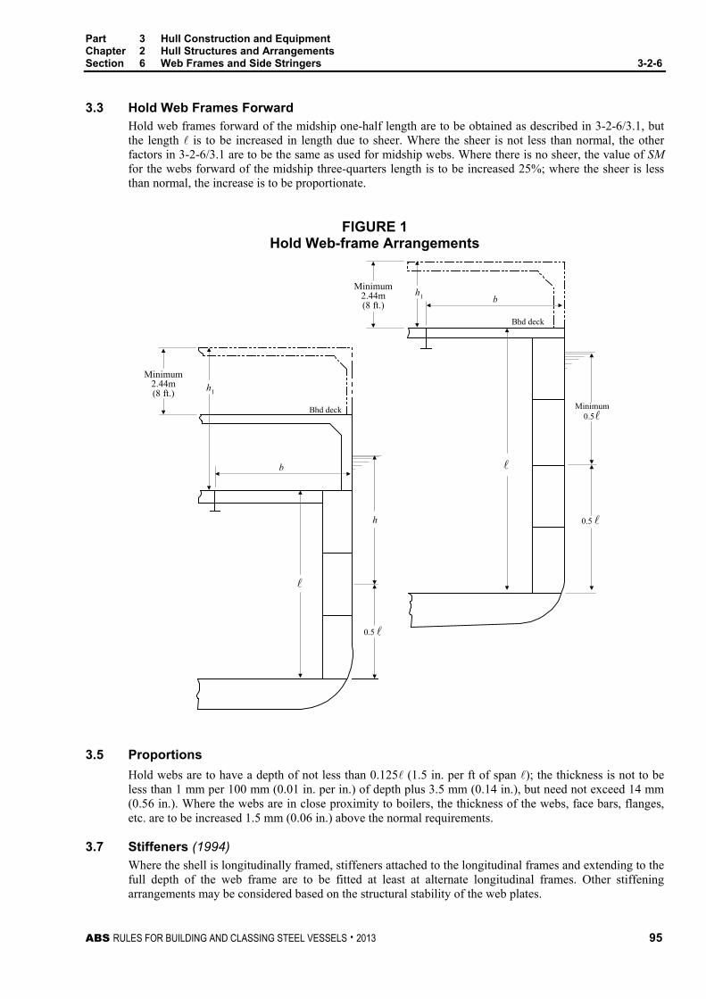
Part 3 Hull Construction and Equipment Chapter 2 Hull Structures and Arrangements Section 6 Web Frames and Side Stringers 3-2-6
ABS RULES FOR BUILDING AND CLASSING STEEL VESSELS . 2013 95
3.3 Hold Web Frames Forward Hold web frames forward of the midship one-half length are to be obtained as described in 3-2-6/3.1, but the length is to be increased in length due to sheer. Where the sheer is not less than normal, the other factors in 3-2-6/3.1 are to be the same as used for midship webs. Where there is no sheer, the value of SM for the webs forward of the midship three-quarters length is to be increased 25%; where the sheer is less than normal, the increase is to be proportionate.
FIGURE 1 Hold Web-frame Arrangements
0.5
Minimum2.44m(8 ft.)
Minimum0.5...
Minimum2.44m(8 ft.)
0.5
Bhd deck
Bhd deck
h1
b
h
bh1
3.5 Proportions Hold webs are to have a depth of not less than 0.125 (1.5 in. per ft of span ); the thickness is not to be less than 1 mm per 100 mm (0.01 in. per in.) of depth plus 3.5 mm (0.14 in.), but need not exceed 14 mm (0.56 in.). Where the webs are in close proximity to boilers, the thickness of the webs, face bars, flanges, etc. are to be increased 1.5 mm (0.06 in.) above the normal requirements.
3.7 Stiffeners (1994) Where the shell is longitudinally framed, stiffeners attached to the longitudinal frames and extending to the full depth of the web frame are to be fitted at least at alternate longitudinal frames. Other stiffening arrangements may be considered based on the structural stability of the web plates.

Part 3 Hull Construction and Equipment Chapter 2 Hull Structures and Arrangements Section 6 Web Frames and Side Stringers 3-2-6
96 ABS RULES FOR BUILDING AND CLASSING STEEL VESSELS . 2013
3.9 Tripping Bracket (1994) Tripping brackets are to be fitted at intervals of about 3 m (10 ft) and near the change of section. Where the breadth of the flanges on either side of the web exceeds 200 mm (8 in.), tripping brackets are to be arranged to support the flange.
3.11 Tween-deck Webs Tween-deck webs are to be fitted below the bulkhead deck over the hold webs, as may be required to provide continuity of transverse strength above the main webs in the holds and machinery space.
5 Side Stringers
5.1 Hold Stringers Each hold stringer, in association with web frames and transverse frames, is to have a section modulus SM not less than obtained from the following equation:
SM = 4.74chs2 cm3
SM = 0.0025chs2 in3
where
c = 1.50
h = vertical distance, in m (ft), from the middle of s to the load line, or to two-thirds of the distance from the keel to the bulkhead deck, or 1.8 m (6 ft), whichever is greatest
s = sum of the half lengths, in m (ft), (on each side of the stringer) of the frames supported
= span, in m (ft), between web frames, or between web frame and bulkhead; where brackets are fitted, the length may be modified
5.3 Proportions Hold stringers are to have a depth of not less than 0.125 (1.5 in. per ft of span ) plus one-quarter of the depth of the slot for the frames, but need not exceed the depth of the web frames to which they are attached; in general, the depth is not to be less than 3 times the depth of the slots or the slots are to be fitted with filler plates; the thickness is not to be less than that determined by the equation in 3-2-6/9.1. Where the stringers are in close proximity to boilers, the thickness of the stringer plates, face bars, flanges, etc. are to be increased 1.5 mm (0.06 in.) above the normal requirements.
5.5 Stiffeners (1994) Stiffeners attached to the frame and extending to the full depth of the stringer are to be fitted on alternate transverse frames. Other stiffening arrangement may be considered based on the structural stability of the web plates.
5.7 Tripping Brackets (1994) The arrangement of tripping brackets is to be in accordance with 3-2-6/3.9.
7 Structural Arrangements and Details
7.1 Brackets of Girders, Webs, and Stringers Where brackets are fitted having thickness not less than the girder or web plates, the value for , as defined in this Section, Section 3-2-8, Section 3-2-9, and Section 3-2-10, may be modified in accordance with the following.

Part 3 Hull Construction and Equipment Chapter 2 Hull Structures and Arrangements Section 6 Web Frames and Side Stringers 3-2-6
ABS RULES FOR BUILDING AND CLASSING STEEL VESSELS . 2013 97
i) Where the face area on the bracket is not less than one-half that on the girder or web and the face plate or flange on the girder or web is carried to the bulkhead or base, the length may be measured to a point 150 mm (6 in.) on to the bracket.
ii) Where the face area on the bracket is less than one-half that on the girder or web and the face plate or flange on the girder or web is carried to the bulkhead or base, may be measured to a point where the area of the bracket and its flange, outside the line of the girder or web, is equal to the flange area on the girder.
iii) Where the face plate or flange area of the girder or web is carried along the face of the bracket, which may be curved for the purpose, may be measured to the point of the bracket.
iv) Brackets are not to be considered effective beyond the point where the arm on the girder or web is 1.5 times the length of the arm on the bulkhead or base; in no case is the allowance in at either end to exceed one-quarter of the overall length of the girder or web.
7.3 End Connections End connections of all girders, webs and stringers should be balanced by effective supporting members on the opposite side of bulkheads, tank tops, etc., and their attachments are to be effectively welded.
End connections of side stringers are to be for the full depth of the web plate. Where the stringers are the same depth as the web frame, the standing flanges of the side stringers are to be attached.
9 Peak Stringers
9.1 Peak Stringer-plate Thickness The peak stringer-plate thickness is not to be less than that obtained from the following equation.
t = 0.014L + 7.2 mm for L ≤ 200 m
t = 0.007L + 8.6 mm for 200 < L ≤ 427 m
t = 0.00017L + 0.28 in. for L ≤ 655 ft
t = 0.00008L + 0.34 in. for 655 < L ≤ 1400 ft
where
t = plate thickness, in mm (in.).
L = length of vessel, as defined in 3-1-1/3.1, in m (ft)
9.3 Peak Stringer-plate Breadth The peak stringer-plate breadth is not to be less than that obtained from the following equation.
b = 8.15L + 6 mm for L ≤ 100 m
b = 2.22L + 600 mm for 100 < L ≤ 427 m
b = 0.098L + 0.25 in. for L ≤ 330 ft
b = 0.027L + 23.5 in. for 330 < L ≤ 1400 ft
where
b = breadth of peak stringer-plate, in mm (in.)
L = length of vessel, as defined in 3-1-1/3.1, in m (ft)
Where beams or struts are not fitted on every frame, the edge of the stringer is to be adequately stiffened by a flange or face bar.

98 ABS RULES FOR BUILDING AND CLASSING STEEL VESSELS . 2013
P A R T S e c t i o n 7 : B e a m s
3 C H A P T E R 2 Hull Structures and Arrangements
S E C T I O N 7 Beams
1 General
1.1 Arrangement Transverse beams are to be fitted on every frame. Beams, transverses and girders are to have adequate structural stability.
1.3 Design Head Where decks are designed to scantling heads less than those specified in this Section, a notation indicating the restricted deck loading will be entered in the Record.
3 Beams
3.1 Strength Requirement Each beam, in association with the plating to which it is attached, is to have a section modulus SM as obtained from the following equation:
SM = 7.8chs2 cm3
SM = 0.0041chs2 in3
where
c = 0.540 for half beams, for beams with centerline support only, for beams between longitudinal bulkheads, and for beams over tunnels or tunnel recesses
= 0.585 for beams between longitudinal deck girders. For longitudinal beams of platform decks and between hatches at all decks
= 0.90 for beams at deep-tank tops supported at one or both ends at the shell or on longitudinal bulkheads
= 1.00 for beams at deep-tank tops between longitudinal girders
= 1/(1.709 − 0.651k) for longitudinal beams of strength decks and of effective lower decks
k = SMRY/IA
SMR = required hull girder section modulus amidships in 3-2-1/3.7.1 or 3-2-1/5.5, whichever is applicable, in cm2-m (in2-ft)
Y = distance, in m (ft), from the neutral axis to the deck being considered, always to be taken positive
IA = hull girder moment of inertia of the vessel amidships, in cm2-m2 (in2-ft2)
The values of IA and Y are to be those obtained using the area of the longitudinal beams given by the above equation.
s = spacing of beams, in m (ft)

Part 3 Hull Construction and Equipment Chapter 2 Hull Structures and Arrangements Section 7 Beams 3-2-7
ABS RULES FOR BUILDING AND CLASSING STEEL VESSELS . 2013 99
= distance, in m (ft), from the inner edge of the beam knee to the nearest line of girder support or between girder supports, whichever is greater. Normally is not to be less than 0.2B. Under the top of deep tanks and in way of bulkhead recesses, the supports are to be arranged to limit the span to not over 4.57 m (15 ft)
h = height, in m (ft), as follows
= is normally to be the height measured at the side of the vessel, of the cargo space wherever stores or cargo may be carried. Where the cargo load differs from 7.04 kN/m3 (718 kgf/m3, 44.8 lbf/ft3) multiplied by the tween-deck height, in m (ft), the height is to be proportionately adjusted.
= for bulkhead recesses and tunnel flats is the height, in m (ft), to the bulkhead deck at the centerline; where that height is less than 6.10 m (20 ft), the value of h is to be taken as 0.8 times the actual height plus 1.22 m (4 ft).
= for deep-tank tops is not to be less than two-thirds of the distance from the top of the tank to the top of the overflow; it is not to be less than given in column (e) of 3-2-7/Table 1, appropriate to the length of the vessel, the height to the load line or two-thirds of the height to the bulkhead or freeboard deck, whichever is greatest. The section modulus is not to be less than would be required for cargo beams.
Elsewhere, the value of h may be taken from the appropriate column of 3-2-7/Table 1, as follows.
Weather deck and decks covered only by houses: Column Freeboard decks having no decks below a Freeboard decks having decks below b Forecastle decks (first above freeboard deck) See Note 1 c Bridge decks (first above freeboard deck) c Short bridges, not over 0.1L (first above freeboard deck) d Poop decks (first above freeboard deck) d Long superstructures (first above freeboard deck) forward of midship half-length b Long superstructures (first above freeboard deck) abaft midship half-length forward and forward of midship 3/5 length aft
c
Long superstructures (first above freeboard deck) abaft midship 3/5 length d Superstructure decks (second above freeboard deck) See Note 2 d Superstructure decks (third and higher above freeboard deck) which contain only accommodation spaces f
Lower decks and decks within superstructures: Decks below freeboard decks c Freeboard decks c Superstructure decks d Accommodation decks f
Decks to which side shell plating does not extend, tops of houses, etc.: First tier above freeboard deck d Second tier above freeboard deck See Note 3 e Third and higher tiers above freeboard deck See Note 3 f
Notes 1 See also 3-2-11/9.
2 Where superstructures above the first superstructure extend forward of the amidship 0.5L, the value of h may be required to be increased.
3 Where decks to which the side shell does not extend and are generally used only as weather covering, the value of h may be reduced, but in no case is it to be less than in column (g).
4 Buckling strength of the plating and framing of all decks is to be considered where they are part of the hull girder.

Part 3 Hull Construction and Equipment Chapter 2 Hull Structures and Arrangements Section 7 Beams 3-2-7
100 ABS RULES FOR BUILDING AND CLASSING STEEL VESSELS . 2013
TABLE 1 Values of h for Beams
Meters L a b c d e f g 90 2.56 2.26 1.51 1.20 1.05 0.90 0.46 100 2.76 2.29 1.69 1.30 1.15 0.91 0.46 110 2.90 2.29 1.90 1.44 1.15 0.91 0.46 120 2.90 2.29 1.98 1.64 1.27 0.91 0.46 122 and above 2.90 2.29 1.98 1.68 1.30 0.91 0.46 Feet L a b c d e f g 300 8.50 7.50 5.00 4.00 3.50 3.00 1.50 325 9.00 7.50 5.50 4.25 3.75 3.00 1.50 350 9.50 7.50 6.00 4.50 3.75 3.00 1.50 375 9.50 7.50 6.50 5.00 4.00 3.00 1.50 400 and above 9.50 7.50 6.50 5.50 4.25 3.00 1.50
Values of h for an intermediate length of vessel are to be obtained by interpolation.
3.3 Special Heavy Beams Special heavy beams are to be arranged where the beams may be required to carry special heavy concentrated loads such as at the ends of deckhouses, in way of masts, winches, auxiliary machinery, etc.
3.5 Beams at the Head of Web Frames Beams at the head of web frames are to be suitably increased in strength and stiffness.
3.7 End Connections At the ends of unbracketed longitudinals, inside the line of openings or on platform decks, or at the ends of unbracketed beams, both the web and flange are to be welded to the supporting member. At beam knees or at other bracketed end connections, continuity of strength of the beam or longitudinal is to be maintained at the connection to the bracket and at the connection of the bracket to the supporting member. Welding is to be in accordance with 3-2-19/Table 1.
Deck longitudinals outside the line of openings are to be continuous or, at bulkheads, they are to have end connections that effectively develop their sectional area and resistance to bending.
Where beams or longitudinals are on, or terminate on, the boundaries of tanks or watertight compartments, structural continuity is to be maintained by a suitable back-up structure in way of the end connection, or the end connection is to be effectively extended by bracket or flat bar to an adjacent stiffener, etc.
4 Deck Fittings (2007)
4.1 General The strength of supporting hull structures used for mooring operations and/or normal towing operations at bow, sides and stern are to comply with the requirements of this section.
Deck fittings for mooring and/or towing are to be located on longitudinals, beams and/or girders, which are part of the deck construction so as to facilitate efficient distribution of the mooring and/or towing load. The same attention is to be paid to recessed bitts, if fitted, of their structural arrangements and strength of supporting structures.

Part 3 Hull Construction and Equipment Chapter 2 Hull Structures and Arrangements Section 7 Beams 3-2-7
ABS RULES FOR BUILDING AND CLASSING STEEL VESSELS . 2013 101
4.3 Design Loads Unless greater safe working load (SWL) of deck fittings is specified by the applicant, the minimum design load to be used is the greater values obtained from 3-2-7/4.3.1 or 3-2-7/4.3.2, whichever is applicable:
4.3.1 Mooring Operations The minimum design load for deck fittings for mooring operations is the applicable value obtained from 3-2-7/4.3.1(a) or 3-2-7/4.3.1(b):
4.3.1(a) Mooring Line Force. 1.25 times the breaking strength of the mooring line according to 3-5-1/Table 2 for each equipment number (EN). EN is the corresponding value used for determination of the vessel’s equipment. (See Note) Notes:
1 Side projected area including maximum stacks of deck cargoes is to be taken into account for assessment of lateral wind forces, arrangements of tug boats and selection of mooring lines.
2 (2008) Where the tabular breaking strength exceeds 490 kN (50,000 kgf, 110,200 lbf), the breaking strength of individual mooring line may be reduced with corresponding increase of number of the mooring lines, provided that the total breaking load of all lines aboard the vessel is not less than the total loads as specified in 3-5-1/Table 2. The number of mooring lines is not less than 6 and no one line is to have a strength less than 490 kN. (See also 3-5-1/9.1 and 3-5-1/15.7)
4.3.1(b) Mooring Winch Force. The design load applied to supporting hull structures for winches, etc. is to be 1.25 times the intended maximum brake holding load and, for capstans, 1.25 times the maximum hauling-in force.
4.3.2 Towing Operations The minimum design load for deck fittings for towing operations is the applicable value obtained from 3-2-7/4.3.2(a) or 3-2-7/4.3.2(b):
4.3.2(a) Normal towing operations (e.g., harbor/maneuvering). 1.25 times the intended maximum towing load (e.g., static bollard pull) as indicated on the towing and mooring arrangements plan.
4.3.2(b) Other towing service (e.g., escort). The nominal breaking strength of the tow line according to the 3-5-1/Table 2 for each equipment number (EN). EN is the corresponding value used for determination of the vessel’s equipment. (See Note) Note: Side projected area including maximum stacks of deck cargoes is to be taken into account for assessment
of lateral wind forces, arrangements of tug boats and selection of mooring lines.
4.3.3 Application of Design Loads The design load is to be applied through the mooring line or tow line, whichever is applicable, according to the arrangement shown on the mooring and towing arrangements plan.
The method of application of the design load to the supporting hull structures is to be taken into account such that the total load need not be more than twice the design load specified in 3-2-7/4.3.2 above, i.e., no more than one turn of one line (see 3-2-7/Figure 1 below).

Part 3 Hull Construction and Equipment Chapter 2 Hull Structures and Arrangements Section 7 Beams 3-2-7
102 ABS RULES FOR BUILDING AND CLASSING STEEL VESSELS . 2013
FIGURE 1 Application of Design Loads (2007)
Fitting
Design Load on LineD
esig
n Lo
ad o
n Li
ne
Design Load on Fitting
(Not more than 2 tim
es
design load on lin
e)
When a specific SWL is applied for a deck fitting at the request of the applicant, by which the design load will be greater than the above minimum values, the strength of the supporting hull structures is to be designed using this specific design load.
4.5 Supporting Structures 4.5.1 Arrangement
The reinforced structural members (e.g., carling) are to be arranged beneath the deck where deck fittings are located and effectively distribute the loads from deck fittings for any variation of direction (horizontally and vertically).
4.5.2 Line Forces The acting point of the mooring and/or towing force on deck fittings is to be taken at the attachment point of a mooring line or a towing line, as applicable.
4.5.3 Allowable stresses Allowable stresses under the design load conditions as specified in 3-2-7/4.3 are as follows:
• Normal stress: 100% of the specified minimum yield point of the material;
• Shearing stress: 60% of the specified minimum yield point of the material;
No stress concentration factors being taken into account. Normal stress is the sum of bending stress and axial stress with the corresponding shearing stress acting perpendicular to the normal stress.
4.7 Scantlings 4.7.1 Net Scantlings
The net minimum scantlings of the supporting hull structure are to comply with the requirements given in 3-2-7/4.5. The net thicknesses, tnet, are the member thicknesses necessary to obtain the above required minimum net scantlings. The required gross thicknesses are obtained by adding the total corrosion additions, tc, given in 3-2-7/4.7.2, to tnet.
4.7.2 Corrosion Addition The total corrosion addition, tc, in mm (in.), for both sides of the hull supporting structure is not to be less than the following values:
• Ships covered by Common Structural Rules (CSR) for bulk carriers and CSR for double hull oil tankers: Total corrosion additions defined in these rules
• Other ships: 2.0 (0.08)

Part 3 Hull Construction and Equipment Chapter 2 Hull Structures and Arrangements Section 7 Beams 3-2-7
ABS RULES FOR BUILDING AND CLASSING STEEL VESSELS . 2013 103
5 Container Loading
5.1 General Where it is intended to carry containers, the exact locations of the container pads and the maximum total static load on the pads are to be indicated on the plans. Where the pads are not in line with the supporting structures, headers are to be provided to transmit the loads to these members.
5.3 Strength Requirements Each member intended to support containers is to have a section modulus, SM, in cm3 (in3), not less than obtained from the following equation.
SM = M/f
where
M = maximum bending moment due to maximum static container loading, in kN-cm, (tf-cm, Ltf-in)
f = permissible maximum bending stress, as given in 3-2-7/Table 2
In determining the maximum bending moment, members may be considered fixed-ended, provided that the member is continuous over the adjacent spans or is effectively attached to a bulkhead stiffener or frame or has end connections in accordance with 3-2-7/3.7. Where this is not the case, the member is to be considered simply-supported. Where weather deck containers are supported by pedestals, the section modulus required by 3-2-7/3, with h equal to the distance between the deck and the underside of the container, but not greater than 50% of the value given in 3-2-7/Table 1, is to be added to the above required section modulus.
7 Higher-strength Materials
7.1 General In general, applications of higher-strength materials for deck beams are to meet the requirements of this section, but may be modified as permitted by the following paragraph. Calculations are to be submitted to show adequate provision against buckling.
7.3 Beams of Higher-strength Materials Each beam of higher-strength material, in association with the higher-strength plating to which it is attached, is to have a section modulus SMhts not less than obtained from the following equation.
SMhts = 7.8chs2Q cm3
SMhts = 0.0041chs2Q in3
where c, h, s and are as defined in 3-2-7/3 and Q is as defined in 3-2-1/5.5.
TABLE 2 Values of f (Ordinary-strength Steel)
kN/cm2 tf/cm2 Ltf/in2 Effective longitudinal members 12.36 1.26 8
Transverse members and longitudinal members inside the line of openings 13.90 1.42 9
The net sectional area of the web of the member, in cm2 (in2), including effective brackets where applicable, is to be not less than obtained from the following equation:
A = F/q F = shearing force at the point under consideration, in kN, (tf, Ltf)
q = allowable average shear stress in the web, not to exceed 10.35 kN/cm2 (1.055 tf/cm2, 6.7 Ltf/in2)

104 ABS RULES FOR BUILDING AND CLASSING STEEL VESSELS . 2013
P A R T S e c t i o n 8 : P i l l a r s , D e c k G i r d e r s a n d T r a n s v e r s e s
3 C H A P T E R 2 Hull Structures and Arrangements
S E C T I O N 8 Pillars, Deck Girders and Transverses
1 General (1997)
1.1 Arrangements – General Tween-deck pillars are to be arranged directly above those in the holds, or effective means are to be provided for transmitting their loads to the supports below. Pillars are to be fitted in line with a double-bottom girder or floor, or as close thereto as practicable. The seating under them is to be of ample strength and is to provide effective distribution of the load. Lightening holes are to be omitted in floors and girders directly under hold pillars.
Where longitudinal beams are used on more than one deck, transverses on the uppermost continuous deck and decks below, and on long superstructures and deck houses are to be fitted at the same vertical plane.
Special support is to be arranged at the ends and corners of deckhouses, in machinery spaces, at ends of partial superstructures and under heavy concentrated weights. For forecastle decks, see also 3-2-11/9.
1.3 Container Loading Where it is intended to carry containers, the structure is to comply with 3-2-7/5.
3 Pillars
3.1 Permissible Load (1994) The permissible load Wa of a pillar or strut is to be obtained from the following equation which will, in all cases, be equal to or greater than the calculated load W as determined in accordance with 3-2-4/7.7, 3-2-8/3.3, 3-2-8/3.5 or 3-2-8/3.7, as appropriate.
Wa = (k − n/r)A kN (tf, Ltf)
where
k = 12.09 (1.232, 7.83) ordinary strength steel
= 16.11 (1.643, 10.43) HT32 strength steel
= 18.12 (1.848, 11.73) HT36 strength steel
= unsupported span of the pillar or strut, in m (ft), measured from the top of the inner bottom, deck or other structure on which the pillar is based to the underside of the beam or girder supported.
r = least radius of gyration, in cm (in.)
A = cross sectional area of strut, in cm2 (in2)
n = 4.44 (0.452, 0.345) ordinary strength steel
= 7.47 (0.762, 0.581) HT32 strength steel
= 9.00 (0.918, 0.699) HT36 strength steel

Part 3 Hull Construction and Equipment Chapter 2 Hull Structures and Arrangements Section 8 Pillars, Deck Girders and Transverses 3-2-8
ABS RULES FOR BUILDING AND CLASSING STEEL VESSELS . 2013 105
3.3 Calculated Load The calculated load W for a specific pillar is to be obtained from the following equation:
W = nbhs kN (tf, Ltf)
where
n = 7.04 (0.715, 0.02)
b = mean breadth of the area supported, in m (ft)
h = height above the area supported as defined below, in m (ft)
s = mean length of the area supported, in m (ft)
For pillars spaced not more than two frame spaces, the height h is to be taken as the distance from the deck supported to a point 3.80 m (12.5 ft) above the freeboard deck.
For widely-spaced pillars, the height h is to be taken as the distance from the deck supported to a point 2.44 m (8 ft) above the freeboard deck, except in the case of such pillars immediately below the freeboard deck, in which case the value of h is not to be less than given in 3-2-7/Table 1, Column a. In measuring the distance from the deck supported to the specified height above the freeboard deck, the height for any tween decks devoted to passenger or crew accommodation may be taken as the height given in 3-2-7/3 for bridge-deck beams.
The height h for any pillar under the first superstructure above the freeboard deck is not to be less than 2.44 m (8 ft). The height h for any pillar is not to be less than the height given in 3-2-7/3 for the beams at the top of the pillar plus the sum of the heights given in the same paragraph for the beams of all complete decks and one-half the heights given for all partial superstructures above.
The height h for pillars under bulkhead recesses or the tops of tunnels is not to be less than the distance from the recess or tunnel top to the bulkhead deck at the centerline.
3.5 Special Pillars Special pillars which are not directly in line with those above, or which are not on the lines of the girders, but which support the loads from above or the deck girders through a system of supplementary fore and aft or transverse girders, such as at hatch ends where the pillars are fitted only on the centerline, are to have the load W, for use with the equation proportionate to the actual loads transmitted to the pillars through the system of girders with modifications to the design value of h as described in 3-2-8/3.3.
3.7 Pillars Under the Tops of Deep Tanks (1994) Pillars under the tops of deep tanks are not to be less than required by the foregoing. They are to be of solid sections and to have not less area than cW cm2 (in2) where W and c are obtained as follows:
W = nbhs kN (tf, Ltf)
where
n = 10.5 (1.07, 0.03)
b = breadth of the area of the top of the tank supported by the pillar, in m (ft)
s = length of the area of the top of the tank supported by the pillar, in m (ft)
h = height, as required by 3-2-7/3.1, for beams at the top of tanks, in m (ft)
c = 0.1035 (1.015, 0.16) ordinary strength steel
= 0.0776 (0.761, 0.12) HT32 strength steel
= 0.069 (0.677, 0.107) HT36 strength steel

Part 3 Hull Construction and Equipment Chapter 2 Hull Structures and Arrangements Section 8 Pillars, Deck Girders and Transverses 3-2-8
106 ABS RULES FOR BUILDING AND CLASSING STEEL VESSELS . 2013
3.9 Bulkhead Stiffening Bulkheads which support girders, or pillars and longitudinal bulkheads which are fitted in lieu of girders, are to be specially stiffened in such manner as to provide supports not less effective than required for stanchions or pillars.
3.11 Attachments Widely-spaced tubular or solid pillars are to bear solidly at head and heel and are to be attached by welding, properly proportioned on the size of the pillar. The attachments of stanchions or pillars under bulkhead recesses, tunnel tops or deep-tank tops which may be subjected to tension loads are to be specially developed to provide sufficient welding to withstand the tension load.
5 Deck Girders and Transverses
5.1 General Girders and transverses of the sizes required by 3-2-8/5.3 through 3-2-8/5.15 are to be fitted, as required to support the beams. In way of bulkhead recesses and the tops of tanks, they are to be arranged so that the unsupported spans of the beams do not exceed 4.57 m (15 ft). Additional girders are to be fitted, as required under masts, king posts, deck machinery or other heavy concentrated loads. In way of deck girders or special deep beams, the deck plating is to be of sufficient thickness and suitably stiffened to provide an effective part of the girder.
5.3 Deck Girders Clear of Tanks Each deck girder clear of tanks, similar to that shown in 3-2-8/Figure 1, is to have a section modulus SM as obtained from the following equation:
SM = 4.74cbh2 cm3
SM = 0.0025cbh2 in3
where
c = 1.0
b = mean breadth of the area of deck supported, in m (ft)
h = height, as required by 3-2-7/3.1, for the beams supported, in m (ft)
= span between centers of supporting pillars, or between pillar and bulkhead, in m (ft). Where an effective bracket, in accordance with 3-2-6/7.1, is fitted at the bulkhead, the length may be modified.

Part 3 Hull Construction and Equipment Chapter 2 Hull Structures and Arrangements Section 8 Pillars, Deck Girders and Transverses 3-2-8
ABS RULES FOR BUILDING AND CLASSING STEEL VESSELS . 2013 107
FIGURE 1 Deck Girders and Pillars
CL
Bhd
see 3-2-6/3.3
b
b
For girders
Superstructuredeck
Freeboarddeck
Mid distance fromgirder to beam knee
s For pillars
For girders
Freeboard deck
Superstructure deck
Forpillars
5.5 Deck Transverses Clear of Tanks Each deck transverse supporting longitudinal deck beams is to have a section modulus SM, as obtained from the equations in 3-2-8/5.3, where:
c = 1.0
b = spacing of deck transverses, in m (ft)
h = height, as required by 3-2-7/3.1, for the beams supported, in m (ft)
= span between supporting girders or bulkheads, or between girder and side frame, in m (ft). Where an effective bracket is fitted at the side frame or bulkhead, the length may be modified. See 3-2-6/7.1.
5.7 Proportions Girders and transverses are to have a depth of not less than 0.0583 (0.7 in. per ft of span ), the thickness is not to be less than 1 mm per 100 mm (0.01 in. per in.) of depth plus 4 mm (0.16 in.), but is not to be less than 8.5 mm (0.34 in.) where the face area is 38 cm2 (6 in2) or less, 10 mm with 63 cm2 (0.40 in. with 10 in2), 12.5 mm with 127 cm2 (0.50 in. with 20 in2) and 15 mm with 190 cm2 (0.60 in. with 30 in2) or over. The thickness for intermediate area may be obtained by interpolation.

Part 3 Hull Construction and Equipment Chapter 2 Hull Structures and Arrangements Section 8 Pillars, Deck Girders and Transverses 3-2-8
108 ABS RULES FOR BUILDING AND CLASSING STEEL VESSELS . 2013
5.9 Tripping Brackets (1994) Tripping brackets are to be fitted at intervals of about 3 m (10 ft.) and near the change of section. Where the breadth of the flanges on either side of the web exceeds 200 mm (8 in.), tripping brackets are to be arranged to support the flange. Additional supports are to be provided for the flanges where their breadth exceeds 400 mm (16 in.).
5.11 End Attachments The ends of deck girders and transverses are to be effectively attached by welding.
5.13 Deck Girders and Transverses in Tanks Deck girders and transverses in tanks are to be obtained in the same manner as given in 3-2-8/5.3, except that the value of c is to be equal to 1.50 and the minimum depth of the girder is to be 0.0833 (1 in. per ft of span ). The minimum thickness, sizes and arrangements of the stiffeners, tripping brackets and end connections are to be the same as given in 3-2-8/5.7, 3-2-8/5.9, and 3-2-8/5.11.
5.15 Hatch Side Girders (1997) Scantlings for hatch side girders supporting athwartship shifting beams or supporting hatch covers are to be obtained in the same manner as deck girders (3-2-8/5.3 through 3-2-8/5.13). Such girders along lower deck hatches under trunks in which covers are omitted are to be increased in proportion to the extra load which may be required to be carried, due to loading up into the trunks. The structure on which the hatch covers are seated is to be effectively supported.
Where deep coamings are fitted above decks, such as at weather decks, the girder below deck may be modified so as to obtain a section modulus, when taken in conjunction with the coaming up to and including the horizontal coaming stiffener, of not less than 35% more than required by 3-2-8/5.3.
Where hatch side girders are not continuous under deck beyond the hatchways to the bulkheads, brackets extending for at least two frame spaces beyond the ends of the hatchways are to be fitted. Where hatch side girders are continuous beyond the hatchways, care is to be taken in proportioning their scantlings beyond the hatchway. Where the hatch side coaming is extended beyond the hatchway, it is not to be connected to the end bulkheads of superstructures or deckhouses, except where it is shown to be appropriate by detailed analysis.
Gusset plates are to be fitted at hatchway corners, arranged so as to effectively tie the flanges of the side coamings and extension pieces or continuous girders and the hatch-end beam flanges both beyond and in the hatchway.
7 Hatch-end Beams
7.1 Hatch-end Beam Supports Each hatch-end beam, similar to that shown in 3-2-8/Figure 2, which is supported by a centerline pillar without a pillar at the corner of the hatchway, is to have a section modulus SM not less than obtained from the following equations:
7.1.1 Where Deck Hatch-side Girders are Fitted Fore and Aft Beyond the Hatchways SM = K (AB + CD) h cm3
SM = 5.267K (AB + CD) h 10-4 in3
7.1.2 Where Girders are not Fitted on the Line of the Hatch Side Beyond the Hatchway SM = KABh cm3
SM = 5.267KABh 10-4 in3
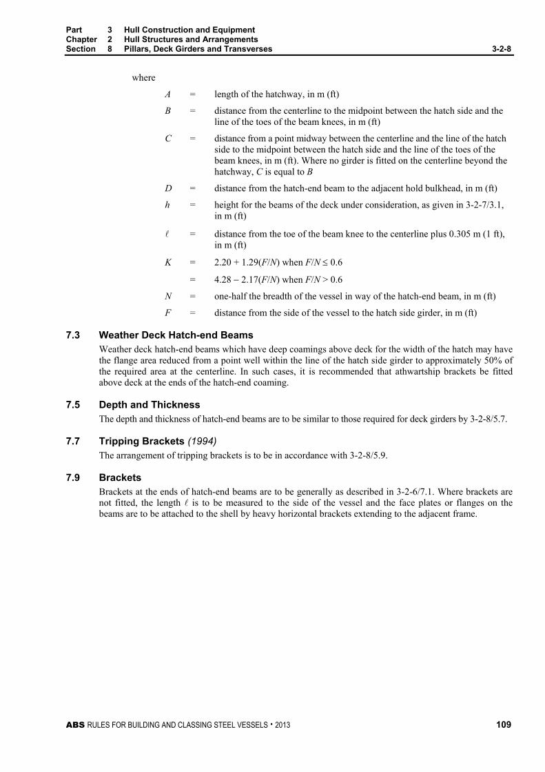
Part 3 Hull Construction and Equipment Chapter 2 Hull Structures and Arrangements Section 8 Pillars, Deck Girders and Transverses 3-2-8
ABS RULES FOR BUILDING AND CLASSING STEEL VESSELS . 2013 109
where
A = length of the hatchway, in m (ft)
B = distance from the centerline to the midpoint between the hatch side and the line of the toes of the beam knees, in m (ft)
C = distance from a point midway between the centerline and the line of the hatch side to the midpoint between the hatch side and the line of the toes of the beam knees, in m (ft). Where no girder is fitted on the centerline beyond the hatchway, C is equal to B
D = distance from the hatch-end beam to the adjacent hold bulkhead, in m (ft)
h = height for the beams of the deck under consideration, as given in 3-2-7/3.1, in m (ft)
= distance from the toe of the beam knee to the centerline plus 0.305 m (1 ft), in m (ft)
K = 2.20 + 1.29(F/N) when F/N ≤ 0.6
= 4.28 − 2.17(F/N) when F/N > 0.6
N = one-half the breadth of the vessel in way of the hatch-end beam, in m (ft)
F = distance from the side of the vessel to the hatch side girder, in m (ft)
7.3 Weather Deck Hatch-end Beams Weather deck hatch-end beams which have deep coamings above deck for the width of the hatch may have the flange area reduced from a point well within the line of the hatch side girder to approximately 50% of the required area at the centerline. In such cases, it is recommended that athwartship brackets be fitted above deck at the ends of the hatch-end coaming.
7.5 Depth and Thickness The depth and thickness of hatch-end beams are to be similar to those required for deck girders by 3-2-8/5.7.
7.7 Tripping Brackets (1994) The arrangement of tripping brackets is to be in accordance with 3-2-8/5.9.
7.9 Brackets Brackets at the ends of hatch-end beams are to be generally as described in 3-2-6/7.1. Where brackets are not fitted, the length is to be measured to the side of the vessel and the face plates or flanges on the beams are to be attached to the shell by heavy horizontal brackets extending to the adjacent frame.

Part 3 Hull Construction and Equipment Chapter 2 Hull Structures and Arrangements Section 8 Pillars, Deck Girders and Transverses 3-2-8
110 ABS RULES FOR BUILDING AND CLASSING STEEL VESSELS . 2013
FIGURE 2 Hatch-end Beams
A
D
B N C
F
305 mm (1 ft)
305 mm (1 ft)
CL
Center Support
Girder
Mid-distance betweengirder and knee
Mid-distance betweensupports
CL
9 Higher-strength Materials
9.1 General In general, applications of higher-strength materials for deck girders and deck transverses are to meet the requirements of this section, but may be modified as permitted by the following paragraphs. Calculations are to be submitted to show adequate provision to resist buckling.
9.3 Girders and Deck Transverses Each girder and deck transverse of higher-strength material, in association with the higher-strength plating to which they are attached, are generally to comply with the requirements of the appropriate preceding paragraphs of this section and is to have a section modulus SMhts not less than obtained from the following equation:
SMhts = SM(Q)
where
SM = required section modulus in ordinary-strength material as determined elsewhere in this section
Q = as defined in 3-2-1/5.5

ABS RULES FOR BUILDING AND CLASSING STEEL VESSELS . 2013 111
P A R T S e c t i o n 9 : W a t e r t i g h t B u l k h e a d s a n d D o o r s
3 C H A P T E R 2 Hull Structures and Arrangements
S E C T I O N 9 Watertight Bulkheads and Doors
1 General
1.1 Application All vessels are to be provided with strength and watertight bulkheads in accordance with this section. In vessels of special type, alternative arrangements are to be specially approved. For passenger vessels, see Part 5C, Chapter 7. In all cases, the plans submitted are to clearly show the location and extent of the bulkheads. Watertight bulkheads constructed in accordance with the Rules will be recorded in the Record as WT (watertight), the symbols being prefixed in each case by the number of such bulkheads.
1.3 Openings and Penetrations (2006) The number of openings in watertight subdivisions is to be kept to a minimum, compatible with the design and proper working of the vessel. Where penetrations of watertight bulkheads and internal decks (see 3-2-15/17.3) are necessary for access, piping, ventilation, electrical cables, etc., arrangements are to be made to maintain the watertight integrity. Relaxation in the watertightness of openings above the freeboard deck may be considered, provided it is demonstrated that any progressive flooding can be easily controlled and that the safety of the vessel is not impaired.
Ventilation penetrations through watertight subdivision bulkheads are to be avoided. Where penetrations are unavoidable, the ventilation ducting is to satisfy watertight bulkhead requirements or watertight closing appliances are to be installed at the bulkhead penetrations. For ventilation penetrations below the bulkhead deck or below damage equilibrium waterlines, the closing appliances are to be operable from the bridge. Where the penetration is located above the bulkhead deck and damage waterline, local manual controls may be provided at the closing appliances, on one or both sides of the bulkhead, so that the controls will be accessible in the prescribed flooded conditions.
1.5 Sluice Valves and Cocks (1997) No valve or cock for sluicing purposes is to be fitted on a collision bulkhead. Where fitted on other watertight bulkheads, sluice valves or cocks are to comply with the requirements of 4-6-2/9.7.4.
1.7 Strength Bulkheads All vessels are to have suitable arrangements to provide effective transverse strength and stiffness of the hull. This may be accomplished by fitting transverse bulkheads extending to the strength deck. In vessels of special type, equivalent transverse strength may be obtained by fitting substantial partial bulkheads, deep webs or combinations of these, so as to maintain effective transverse continuity of structure.
1.9 Testing Requirements for testing are contained in Part 3, Chapter 7.

Part 3 Hull Construction and Equipment Chapter 2 Hull Structures and Arrangements Section 9 Watertight Bulkheads and Doors 3-2-9
112 ABS RULES FOR BUILDING AND CLASSING STEEL VESSELS . 2013
3 Arrangement of Watertight Bulkheads
3.1 Collision Bulkhead 3.1.1 General
A collision bulkhead is to be fitted on all vessels. It is to be intact, that is, without openings except as permitted in 4-6-2/9.7.3. It is to extend, preferably in one plane, to the freeboard deck. In the case of vessels having long superstructures at the fore end, it is to be extended weathertight to the superstructure deck. The extension need not be fitted directly over the bulkhead below, provided that the location of the extension meets the following requirements and the part of the deck which forms the step is made effectively weathertight.
On vessels with bow-doors, that part of their sloping loading ramps that form part of the extension of a collision bulkhead, and are more than 2.3 m (7.5 ft) above the freeboard deck, may extend forward of the limit below. See 3-2-9/Figure 1.
3.1.2 Location (1 July 2010) The collision bulkhead is to be located at any point not less than 0.05Lr or 10 m (32.8 ft), whichever is less, abaft the reference point. At no point on any vessel, except as specially permitted, is it to be further than 0.08Lr or 0.05Lr + 3 m (9.84 ft), whichever is greater, from the reference point.
3.1.3 Definitions The reference point in determining the location of the collision bulkhead is the forward end of Lr except that in the case of vessels having any part of the underwater body, such as bulbous bow, extending forward of the forward end of Lr, the required distances are to be measured from a reference point located a distance forward of the forward end of Lr. This distance x is the least of the following:
i) Half the distance between the forward end of Lr and the extreme forward end of the extension, p/2
ii) 0.015Lr or
iii) 3 m (9.84 ft). See 3-2-9/Figure 2.
Lr = (for passenger vessels) length between perpendiculars at the deepest subdivision load line. The forward end of Lr is to coincide with the fore side of stem on the waterline on which Lr is measured.
Lr = (for other vessels) Lf as defined in 3-1-1/3.3.
3.3 After-peak Bulkhead An after-peak bulkhead is to be fitted in all screw vessels arranged to enclose the shaft tubes in a watertight compartment. The bulkhead is to extend to the strength deck, or efficient partial bulkheads are to extend thereto. The requirements of enclosing the shaft tube in a watertight compartment may be specially considered where such an arrangement is impracticable.

Part 3 Hull Construction and Equipment Chapter 2 Hull Structures and Arrangements Section 9 Watertight Bulkheads and Doors 3-2-9
ABS RULES FOR BUILDING AND CLASSING STEEL VESSELS . 2013 113
FIGURE 1 Collision Bulkhead in Vessels with Bow Door (1 July 2010)
y1 = 0.05Lr or 10m (32.8 ft) whichever is lessy2 = 0.08Lr or 0.05Lr + 3m (9.84 ft)
whichever is greater
Loading Ramp
BHD orFBD Dk
2.3m(7.5 ft)
y1
y2
R.P. orFP
FIGURE 2 Reference Point for Vessels with Bulbous Bow
FP
p
x
R.P.
x = p/2 0.015Lr or 3m (9.84 ft) whichever is least
3.5 Machinery Spaces Machinery spaces are to be enclosed by watertight bulkheads which extend to the freeboard deck. In those cases where the length of the machinery space is unusually large in association with a small freeboard, the attention of designers is called to the desirability of extending the bulkheads to a deck above the freeboard deck, the fitting of an intermediate bulkhead, or the inclusion of a watertight deck over the machinery space which, in association with tight casings, might confine the amount of flooding in the event of damage in way of the machinery space. See 3-3-1/3.3.

Part 3 Hull Construction and Equipment Chapter 2 Hull Structures and Arrangements Section 9 Watertight Bulkheads and Doors 3-2-9
114 ABS RULES FOR BUILDING AND CLASSING STEEL VESSELS . 2013
3.7 Hold Bulkheads 3.7.1 General (1997)
In addition to the foregoing required watertight bulkheads, the number and arrangement of hold bulkheads are to satisfy the subdivision and damage stability requirements in 3-3-1/3.3. Review procedures for this requirement are indicated in 3-3-1/5.
3.7.2 Carriage of Water Ballast in Cargo Holds Where a cargo hold is intended to be used for the carriage of water ballast or liquid cargoes, the hold is in general to be completely filled and the scantlings of the inner bottom, side structure, transverse bulkheads, deck and hatch covers are also to be in accordance with Section 3-2-10. The hatch cover and securing devices are to be suitable for the internal loading. See 3-2-15/9.
Special consideration may be given to the scantlings of cargo holds partially filled with water ballast or liquid cargoes. Full particulars are to be submitted.
3.9 Chain Lockers (2012) Chain lockers and chain pipes are to be made watertight up to the weather deck. The arrangements are to be such that accidental flooding of the chain locker cannot result in damage to auxiliaries or equipment necessary for the proper operation of the vessel nor in successive flooding into other spaces. Bulkheads between separate chain lockers not forming a part of subdivision bulkhead (see 3-2-9/Figure 2A below), or bulkheads which form a common boundary of chain lockers (see 3-2-9/Figure 2B below), need not be watertight.
Where means of access into chain lockers are provided, they are to be closed by a substantial cover secured by closely spaced bolts. Doors are not permitted.
Where a means of access to chain lockers is located below the weather deck, the access cover and its securing arrangements are to be in accordance with recognized standards (such as ISO 5894-1999), or equivalent for watertight manhole covers. Butterfly nuts and/or hinged bolts are prohibited as the securing mechanism for the access cover.
For closure of chain pipes, see 3-2-15/21.11.
The arrangements on vessels that are not subject to the International Convention on Load Lines or its Protocol may be specially considered.
FIGURE 2A (2007) FIGURE 2B (2007)

Part 3 Hull Construction and Equipment Chapter 2 Hull Structures and Arrangements Section 9 Watertight Bulkheads and Doors 3-2-9
ABS RULES FOR BUILDING AND CLASSING STEEL VESSELS . 2013 115
5 Construction of Watertight Bulkheads
5.1 Plating Plating is to be of the thickness obtained from the following equation:
t = sk qh /c + 1.5 mm but not less than 6 mm or s/200 + 2.5 mm, whichever is greater
t = sk qh /c + 0.06 in. but not less than 0.24 in. or s/200 + 0.10 in., whichever is greater
where
t = thickness, in mm (in).
s = spacing of stiffeners, in mm (in.)
k = (3.075 α − 2.077)/(α + 0.272) where 1 ≤ α ≤ 2
= 1.0 where α > 2
α = aspect ratio of the panel (longer edge/shorter edge)
q = 235/Y N/mm2 (24/Y kgf/mm2, 34,000/Y psi)
Y = specified minimum yield point or yield strength, in N/mm2 (kgf/mm2, psi), as defined in 2-1-1/13, for the higher-strength material or 72% of the specified minimum tensile strength, whichever is the lesser
h = (1998) distance from the lower edge of the plate to the deepest equilibrium waterline in the one compartment damaged condition, in m (ft).
• For passenger vessels, h is to be taken as not less than the distance to the margin line.
• For cargo vessels, h is to be not less than the distance to the bulkhead deck at center unless a deck lower than the uppermost continuous deck is designated as the freeboard deck, as allowed in 3-1-1/13.1. In such case, h is to be not less than the distance to the designated freeboard deck at center.
c = 254 (254, 460) for collision bulkhead
= 290 (290, 525) for other watertight bulkhead
The plating of afterpeak bulkheads below the lowest flat is not to be less than required for solid floors in the after peak space. See 3-2-5/9.
5.3 Stiffeners Each stiffener, in association with the plating to which it is attached, is to have a section modulus SM not less than obtained from the following equation:
SM = 7.8chs2 cm3
SM = 0.0041chs2 in3
where
c = 0.30 for stiffeners having effective bracket attachments at both ends of their spans
= 0.43 for stiffeners having effective brackets at one end and supported by clip connections or by horizontal girders at the other end
= 0.56 for stiffeners having clip connections at both ends, or clip connections at one end and supported by horizontal girders at the other end, and for stiffeners in the uppermost tween decks having no end attachments
= 0.60 for other stiffeners having no end attachments and for stiffeners between horizontal girders

Part 3 Hull Construction and Equipment Chapter 2 Hull Structures and Arrangements Section 9 Watertight Bulkheads and Doors 3-2-9
116 ABS RULES FOR BUILDING AND CLASSING STEEL VESSELS . 2013
s = spacing of the stiffeners, in m (ft)
h = (1998) distance, in m (ft), from the middle of to the deepest equilibrium waterline in the one compartment damaged condition.
• For passenger vessels, h is to be taken as not less than the distance to the margin line.
• For cargo vessels, h is to be not less than the distance to the bulkhead deck at center unless a deck lower than the uppermost continuous deck is designated as the freeboard deck, as allowed in 3-1-1/13.1. In such case, h is to be not less than the distance to the designated freeboard deck at center.
• For all vessels, where the distance indicated above is less than 6.10 m (20 ft), h is to be taken as 0.8 times the distance plus 1.22 m (4 ft).
= distance between the heels of the end attachments; where horizontal girders are fitted, is the distance from the heel of the end attachment to the first girder, or the distance between the horizontal girders, in m (ft)
The value of SM for stiffeners on collision bulkheads is to be at least 25% greater than required above for stiffeners on watertight bulkheads.
An effective bracket, for the application of the above values of c, is to have the scantlings not less effective than shown in 3-2-9/Table 1 and is to extend onto the stiffener for a distance at least one-eighth of the length of the stiffener.
5.5 Attachments Lower brackets to inner bottoms are to extend over the floor adjacent to the bulkhead. Where stiffeners cross horizontal girders, they are to be effectively attached.
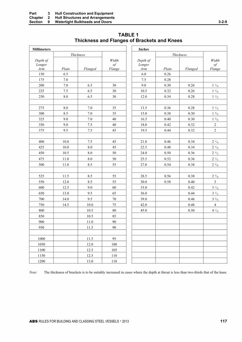
Part 3 Hull Construction and Equipment Chapter 2 Hull Structures and Arrangements Section 9 Watertight Bulkheads and Doors 3-2-9
ABS RULES FOR BUILDING AND CLASSING STEEL VESSELS . 2013 117
TABLE 1 Thickness and Flanges of Brackets and Knees
Millimeters Inches
Depth of Longer
Arm
Thickness Depth of Longer
Arm
Thickness
Plain
Flanged
Width of
Flange
Plain
Flanged
Width of
Flange
150 6.5 6.0 0.26
175 7.0 7.5 0.28
200 7.0 6.5 30 9.0 0.30 0.26 1 1/4
225 7.5 6.5 30 10.5 0.32 0.26 1 1/4
250 8.0 6.5 30 12.0 0.34 0.28 1 1/2
275 8.0 7.0 35 13.5 0.36 0.28 1 1/2
300 8.5 7.0 35 15.0 0.38 0.30 1 3/4
325 9.0 7.0 40 16.5 0.40 0.30 1 3/4
350 9.0 7.5 40 18.0 0.42 0.32 2
375 9.5 7.5 45 19.5 0.44 0.32 2
400 10.0 7.5 45 21.0 0.46 0.34 2 1/4
425 10.0 8.0 45 22.5 0.48 0.34 2 1/4
450 10.5 8.0 50 24.0 0.50 0.36 2 1/2
475 11.0 8.0 50 25.5 0.52 0.36 2 1/2
500 11.0 8.5 55 27.0 0.54 0.38 2 3/4
525 11.5 8.5 55 28.5 0.56 0.38 2 3/4
550 12.0 8.5 55 30.0 0.58 0.40 3
600 12.5 9.0 60 33.0 0.42 3 1/4
650 13.0 9.5 65 36.0 0.44 3 1/2
700 14.0 9.5 70 39.0 0.46 3 3/4
750 14.5 10.0 75 42.0 0.48 4
800 10.5 80 45.0 0.50 4 1/4
850 10.5 85
900 11.0 90
950 11.5 90
1000 11.5 95
1050 12.0 100
1100 12.5 105
1150 12.5 110
1200 13.0 110
Note: The thickness of brackets is to be suitably increased in cases where the depth at throat is less than two-thirds that of the knee.

Part 3 Hull Construction and Equipment Chapter 2 Hull Structures and Arrangements Section 9 Watertight Bulkheads and Doors 3-2-9
118 ABS RULES FOR BUILDING AND CLASSING STEEL VESSELS . 2013
5.7 Girders and Webs 5.7.1 Strength Requirements
Each girder and web which supports bulkhead stiffeners is to have section modulus SM not less than obtained from the following equation:
SM = 4.74chs2 cm3
SM = 0.0025chs2 in3
where
c = 1.0
h = (1998) vertical distance, in m (ft), to the deepest equilibrium waterline in the one compartment damaged condition from the middle of s in the case of girders and from the middle of in the case of webs.
• For passenger vessels, h is to be taken as not less than the distance to the margin line.
• For cargo vessels, h is to be not less than the distance to the bulkhead deck at center unless a deck lower than the uppermost continuous deck is designated as the freeboard deck, as allowed in 3-1-1/13.1, in which case h is to be not less than the distance to the designated freeboard deck at center.
• For all vessels, where the distance indicated above is less than 6.10 m (20 ft), the value of h is to be 0.8 times the distance plus 1.22 m (4 ft).
s = sum of half lengths (on each side of girder or web) of the stiffeners supported, in m (ft)
= span measured between the heels of the end attachments, in m (ft).Where brackets are fitted, the length may be modified as indicated in 3-2-6/7.1.
The section modulus SM of each girder and web on the collision bulkheads is to be at least 25% greater than required for similar supporting members on watertight bulkheads.
5.7.2 Proportions Girders and webs are to have depths not less than 0.0832 (1 in. per ft of span ) plus one-quarter of the depth of the slots for the stiffeners; the thickness is not to be less than 1 mm per 100 mm (0.01 in. per in.) of depth plus 3 mm (0.12 in.) but need not exceed 11.5 mm (0.46 in.).
5.7.3 Tripping Brackets (1994) Tripping brackets are to be fitted at intervals of about 3 m (10 ft), and near the change of section. Where the width of the face flange exceeds 200 mm (8 in.) on either side of the girder or web, tripping brackets are to be arranged to support the flange.
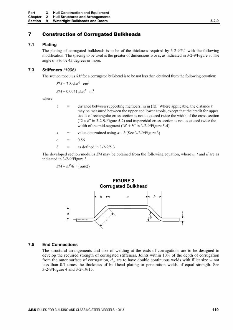
Part 3 Hull Construction and Equipment Chapter 2 Hull Structures and Arrangements Section 9 Watertight Bulkheads and Doors 3-2-9
ABS RULES FOR BUILDING AND CLASSING STEEL VESSELS . 2013 119
7 Construction of Corrugated Bulkheads
7.1 Plating The plating of corrugated bulkheads is to be of the thickness required by 3-2-9/5.1 with the following modification. The spacing to be used is the greater of dimensions a or c, as indicated in 3-2-9/Figure 3. The angle φ is to be 45 degrees or more.
7.3 Stiffeners (1996) The section modulus SM for a corrugated bulkhead is to be not less than obtained from the following equation:
SM = 7.8chs2 cm3
SM = 0.0041chs2 in3
where
= distance between supporting members, in m (ft). Where applicable, the distance may be measured between the upper and lower stools, except that the credit for upper stools of rectangular cross section is not to exceed twice the width of the cross section (“2 × b” in 3-2-9/Figure 5-2) and trapezoidal cross section is not to exceed twice the width of the mid-segment (“b′ + b” in 3-2-9/Figure 5-4)
s = value determined using a + b (See 3-2-9/Figure 3)
c = 0.56
h = as defined in 3-2-9/5.3
The developed section modulus SM may be obtained from the following equation, where a, t and d are as indicated in 3-2-9/Figure 3.
SM = td2/6 + (adt/2)
FIGURE 3 Corrugated Bulkhead
tφ
dc
b a b
7.5 End Connections The structural arrangements and size of welding at the ends of corrugations are to be designed to develop the required strength of corrugated stiffeners. Joints within 10% of the depth of corrugation from the outer surface of corrugation, d1, are to have double continuous welds with fillet size w not less than 0.7 times the thickness of bulkhead plating or penetration welds of equal strength. See 3-2-9/Figure 4 and 3-2-19/15.

Part 3 Hull Construction and Equipment Chapter 2 Hull Structures and Arrangements Section 9 Watertight Bulkheads and Doors 3-2-9
120 ABS RULES FOR BUILDING AND CLASSING STEEL VESSELS . 2013
FIGURE 4 Corrugated Bulkhead End Connections
0.7t
0.1d1
t
d1
FIGURE 5 Corrugated Bulkhead Upper Stool Credit (1996)
b
1) h < 2 × b 2) h ≥ 2 × b
4) h ≥ b' + b3) h < b' + b
b
h
h 2 × b
b
h
b'
b
b'
b
h b' + b

Part 3 Hull Construction and Equipment Chapter 2 Hull Structures and Arrangements Section 9 Watertight Bulkheads and Doors 3-2-9
ABS RULES FOR BUILDING AND CLASSING STEEL VESSELS . 2013 121
9 Watertight Doors
9.1 Doors Used While at Sea (2001) Doors that are used while at sea are to be sliding watertight doors capable of being remotely closed from the bridge and are also to be operable locally from each side of the bulkhead. Indicators are to be provided at the control position showing whether the doors are open or closed, and an audible alarm is to be provided which is to sound whenever the door is closed remotely by power. See also 4-10-1/3.5. The power operated doors, control systems and indicators are to be functional in the event of main power failure. Particular attention is to be paid to minimize the effect of control system failure. Each power-operated sliding watertight door is to be provided with an individual hand-operated mechanism. It is to be possible to open and close the door by hand at the door itself from each side. See also Section 4-10-1.
9.3 Access Doors Normally Closed at Sea (2002) Access doors and access hatch covers (see 3-2-15/17.3) normally closed at sea may be substantially constructed hinged type fitted with gaskets and dogs spaced and designed to ensure that the opening may be closed thoroughly watertight. These closing appliances are to be provided with means of indicating locally and on the bridge whether they are open or closed. A notice is to be affixed to each closing appliance to the effect that it is not to be left open.
Additionally, where a vessel is a Type A ship over 150 m (492 ft) in length or a Type B ship over 100 m (328 ft) in length, with a freeboard less than that based on Table B in Regulation 28 of the International Convention on Load Lines, 1966, the final waterline after flooding, taking into account sinkage, heel and trim, is to be below the lower edge of openings of those doors through which progressive downflooding may take place, unless the doors are remotely operated. Doors separating a main machinery space from the steering gear compartment may be hinged, quick acting type (e.g., all door dogs are in closed/opened position simultaneously by a manually-operated single handle or equivalent), provided that the sill of such doors is above the summer load waterline.
9.5 Doors or Ramps Dividing Large Cargo Spaces Watertight doors or ramps (see 3-2-15/17.3) of satisfactory construction may be fitted to internally subdivide large cargo spaces, provided it is demonstrated to ABS that such doors or ramps are essential.
These doors or ramps may be hinged, rolling or sliding doors or ramps, but are not to be remotely controlled.
Such doors or ramps may be approved on condition that the shipboard personnel close them before the voyage commences and are kept closed during navigation. The time of opening such doors or ramps in port and of closing them before the vessel leaves port is to be recorded and entered in the logbook.
Doors or ramps accessible during the voyage are to be fitted with a device, which prevents unauthorized opening.
9.7 Other Openings Closed at Sea Closing appliances which are to be kept permanently closed at sea, to ensure the watertight integrity of internal openings in watertight bulkheads and decks (see 3-2-15/17.3), that are not fitted with a device which prevents unauthorized opening are to be provided with a notice affixed to each such closing appliance to the effect that it is to be kept closed while the vessel is at sea. Manholes fitted with closely bolted covers need not be so marked.
9.9 Construction Watertight doors are to be of ample strength for the water pressure to which they may be subjected. Doorframes are to be carefully fitted to the bulkheads; where liners are required, the material is to be not readily injured by heat or by deterioration. Sliding doors are to be carefully fitted to the frames.
Where stiffeners are cut in way of watertight doors, the openings are to be framed and bracketed to maintain the full strength of the bulkheads without taking the strength of the doorframes into consideration.

Part 3 Hull Construction and Equipment Chapter 2 Hull Structures and Arrangements Section 9 Watertight Bulkheads and Doors 3-2-9
122 ABS RULES FOR BUILDING AND CLASSING STEEL VESSELS . 2013
9.11 Testing at Sliding Door Manufacturer (1996) Sliding doors are to be tested for operation at the manufacturer’s plant. Hydrostatic testing of sliding doors is also to be carried out at the manufacturer’s plant, with a head of water equivalent to the height to the bulkhead deck or freeboard deck at center.

ABS RULES FOR BUILDING AND CLASSING STEEL VESSELS . 2013 123
P A R T S e c t i o n 1 0 : D e e p T a n k s
3 C H A P T E R 2 Hull Structures and Arrangements
S E C T I O N 10 Deep Tanks
1 General
1.1 Application This Section applies to all deep tanks where the requirements in this Section exceed those of Section 3-2-9.
1.3 Arrangement The arrangement of all deep tanks, together with their intended service and the height of the overflow pipes, is to be clearly indicated on the plans submitted for approval.
Tanks for fresh water or fuel oil or those that are not intended to be kept entirely filled in service, are to have divisions or deep swashes as may be required to minimize the dynamic stress on the structure. Oil or other liquid substances that are flammable are not to be carried in tanks forward of the collision bulkhead.
1.5 Construction The boundary bulkheads of all deep tanks are to be constructed in accordance with the requirements of this Section.
Longitudinal tight divisions, which are fitted for reasons of stability in tanks which are to be entirely filled or empty in service, may be of the scantlings required for watertight bulkheads by Section 3-2-9. In such cases, the tanks are to be provided with feed tanks or deep hatches, fitted with inspection plugs in order to ensure that the tanks on both sides of the bulkhead so designed are kept full when in service.
1.7 Drainage and Air Escape Limber and air holes are to be cut in all parts of the structure, as required, to ensure the free flow to the suction pipes and the escape of air to the vents. Efficient arrangements are to be made for draining the spaces above deep tanks.
1.9 Testing Requirements for testing are contained in Part 3, Chapter 7.
3 Construction of Deep Tank Bulkheads
Where the specific gravity of the liquid exceeds 1.05, the design head, h, in this section is to be increased by the ratio of the specific gravity of the liquid to be carried, to 1.05.
3.1 Plating Plating is to be of thickness obtained from the following equation:
t = (sk qh /254) + 2.5 mm but not less than 6.5 mm or s/150 + 2.5 mm, whichever is greater.
t = (sk qh /460) + 0.10 in. but not less than 0.25 in. or s/150 + 0.10 in., whichever is greater.

Part 3 Hull Construction and Equipment Chapter 2 Hull Structures and Arrangements Section 10 Deep Tanks 3-2-10
124 ABS RULES FOR BUILDING AND CLASSING STEEL VESSELS . 2013
where
t = thickness, in mm (in.)
s = stiffener spacing, in mm (in.)
k = (3.075 α − 2.077)/(α + 0.272) where 1 ≤ α ≤ 2
= 1.0 where α > 2
α = aspect ratio of the panel (longer edge/shorter edge)
q = 235/Y N/mm2 (24/Y kgf/mm2, 34,000/Y psi)
Y = specified minimum yield point or yield strength, in N/mm2 (kgf/mm2, psi), as defined in 2-1-1/13, for the higher-strength material or 72% of the specified minimum tensile strength, whichever is the lesser
h = the greatest of the following distances, in m (ft), from the lower edge of the plate to:
• a point located two-thirds of the distance from the top of the tank to the top of the overflow
• a point located above the top of the tank at a distance not less than given in column (e) of 3-2-7/Table 1, appropriate to the vessel’s length
• the load line
• a point located at two-thirds of the distance to the bulkhead or freeboard deck
3.3 Stiffeners Each stiffener, in association with the plating to which it is attached, is to have section modulus SM not less than obtained from the following equation:
SM = 7.8chs2 cm3
SM = 0.0041chs2 in3
where
c = 0.594 for stiffeners having effective bracket attachments at both ends
= 0.747 for stiffeners having effective bracket attachment at one end and supported by clip connections or by horizontal girders at the other end
c = 0.900 for stiffeners having clip attachments to decks or flats at both ends or having such attachments at one end with the other end supported by horizontal girders
= 1.00 for stiffeners supported at both ends by horizontal girders
s = spacing of the stiffeners, in m (ft)
h = greatest of the following distances, in m (ft), from the middle of to:
• a point located at two-thirds of the distance from the top of the tank to the top of the overflow
• a point located above the top of the tank a distance not less than given in column (e) of 3-2-7/Table 1, appropriate to the vessel’s length
• the load line
• a point located at two-thirds of the distance to the bulkhead or freeboard deck
= distance, in m (ft), between the heels of the end attachments; where horizontal girders are fitted, is the distance from the heel of the end attachment to the first girder or the distance between the horizontal girders.
An effective bracket for the application of these values of c is to have the scantlings not less effective than shown in 3-2-9/Table 1 and is to extend onto the stiffener for a distance at least one-eighth of the length of the stiffener.

Part 3 Hull Construction and Equipment Chapter 2 Hull Structures and Arrangements Section 10 Deep Tanks 3-2-10
ABS RULES FOR BUILDING AND CLASSING STEEL VESSELS . 2013 125
3.5 Tank-top Plating Tops of tanks are to have plating 1 mm (0.04 in.) thicker than would be required for vertical plating at the same level; the thickness is not to be less than required for deck plating. Beams, girders and pillars are to be as required by Section 3-2-7 and Section 3-2-8.
3.7 Girders and Webs 3.7.1 Strength Requirements
Each girder and web which support frames or beams in deep tanks is to have section modulus SM as required by Section 3-2-6 and Section 3-2-8 or as required by this paragraph, whichever is the greater; those which support bulkhead stiffeners are to be as required by this paragraph. The section modulus SM is to be not less than obtained from the following equation.
SM = 4.74chs2 cm3
SM = 0.0025chs2 in3
where
c = 1.50
h = vertical distance, in m (ft), from the middle of s in the case of girders and from the middle of in the case of webs to the same heights to which h for the stiffeners is measured (see 3-2-10/3.3)
s = sum of half lengths (on each side of girder or web) of the frames or stiffeners supported, in m (ft)
= span measured between the heels of the end of the attachments, in m (ft). Where effective brackets are fitted, may be modified as indicated in 3-2-6/7.1.
Where efficient struts are fitted across tanks connecting girders on each side of the tanks and spaced not more than four times the depth of the girder, the value for the section modulus SM for each girder may be one-half that given above.
3.7.2 Proportions Girders, except deck girders (see 3-2-8/5.13), and webs are to have depths not less than 0.145 where no struts or ties are fitted, and 0.0833 where struts are fitted, plus one-quarter of the depth of the slots for the frames or stiffeners. In general, the depth is not to be less than 3 times the depth of the slots; the thickness is not to be less than 1% of the depth plus 3 mm (0.12 in.) but need not exceed 11.5 mm (0.46 in.).
3.7.3 Tripping Brackets (1994) Tripping brackets are to be fitted at intervals of about 3 m (10 ft) and near the change of section. Where the width of the face flange exceeds 200 mm (8 in.) on either side of the girder or web, tripping brackets are to be arranged to support the flange.
3.9 Corrugated Bulkheads Where corrugated bulkheads are used as deep-tank boundaries, the scantlings may be developed from 3-2-9/7. The plating thickness t and value of SM are to be as required by 3-2-10/3.1 and 3-2-10/3.3, respectively, with c = 0.90.

Part 3 Hull Construction and Equipment Chapter 2 Hull Structures and Arrangements Section 10 Deep Tanks 3-2-10
126 ABS RULES FOR BUILDING AND CLASSING STEEL VESSELS . 2013
5 Higher-strength Materials
5.1 General In general, applications of higher-strength materials for deep-tank plating are to meet the requirements of this section, but may be modified as permitted by the following paragraphs. Calculations are to be submitted to show adequate provision to resist buckling.
5.3 Plating Deep-tank plating of higher-strength material is to be of not less thickness than obtained by 3-2-10/3.1.
5.5 Stiffeners Each stiffener of higher-strength material, in association with the higher-strength plating to which it is attached, is to have section modulus SMhts not less than obtained from the following equation:
SMhts = 7.8chs2Q cm3
SMhts = 0.0041chs2Q in3
where c, h, s and are as defined in 3-2-10/3.3 and Q is as defined in 3-2-1/5.5.

ABS RULES FOR BUILDING AND CLASSING STEEL VESSELS . 2013 127
P A R T S e c t i o n 1 1 : S u p e r s t r u c t u r e s , D e c k h o u s e s a n d H e l i c o p t e r D e c k s
3 C H A P T E R 2 Hull Structures and Arrangements
S E C T I O N 11 Superstructures, Deckhouses and Helicopter Decks
1 General Scantlings of Superstructures and Deckhouses
1.1 Side Plating Side plating of superstructures within the amidship 0.4L of the vessel is to be obtained from 3-2-2/3. At the forward and after ends, the plating for 0.1L from each end may be of the thickness obtained from 3-2-2/5.7 and 3-2-2/5.9 for forecastle and poop side plating respectively; beyond 0.1L from each end, the thickness of the plating is to be gradually increased to that required within the amidship 0.4L length.
1.3 Decks (1997)
1.3.1 Superstructures
Decks of superstructures having lengths greater than 0.1L are to be considered as strength decks and are to comply with the requirements of 3-2-3/5. Where 0.1L or less in length, the stringer plate may be the thickness of the side plating and the remainder of the deck plating is to meet the hull girder section modulus requirements of Section 3-2-1 if located within the 0.4L amidships. The thickness of the plating at the forward and aft ends is to be obtained from 3-2-3/Table 1 for forecastle and poop deck plating.
1.3.2 Deckhouses
The top plating of long deckhouses is to be as required by 3-2-3/Table 1 line H. In addition, deckhouses located within 0.4L amidships and having lengths over 0.1L are to have plating meeting the hull girder requirements of Section 3-2-1.
1.5 Frames Frames are to be of the sizes obtained from 3-2-5/5. Web frames or partial bulkheads are to be fitted over main bulkheads and elsewhere as may be required to give effective transverse rigidity to the structure.
1.7 Breaks in Continuity Breaks in the continuity of superstructures are to be specially strengthened (see 3-2-2/11). The arrangements in this area are to be clearly shown on the plans submitted for approval.
3 Exposed Bulkheads
3.1 General (2013) The scantlings of the exposed bulkheads of superstructures and deckhouses are to be in accordance with the following paragraphs, except that the requirements for house side stiffeners need not exceed the requirements of Section 3-2-5 for the side frames directly below the deck on which the house is located. In general, the lowest tier is that on the freeboard deck.
Special consideration may be given to the bulkhead scantlings and sills of access openings of deckhouses which do not protect openings in the freeboard deck, superstructure deck or in the top of a lowest tier deckhouse, or which do not protect machinery casings, provided they do not contain accommodation, or do not protect equipment essential to the operation of the vessel.

Part 3 Hull Construction and Equipment Chapter 2 Hull Structures and Arrangements Section 11 Superstructures, Deckhouses and Helicopter Decks 3-2-11
128 ABS RULES FOR BUILDING AND CLASSING STEEL VESSELS . 2013
Superstructures or deckhouses located within the amidship 0.4L and having lengths greater than 0.1L are to have effective longitudinal scantlings to give a hull girder section modulus through the superstructure or deckhouse equal to that of the main hull girder. The superstructure scantlings are to be in accordance with 3-2-11/1 and the house top and side plating of long deckhouses is to be not less than obtained from equation 5 in 3-2-3/Table 2.
Partial bulkheads, deep webs, etc. are to be fitted at the ends and sides of large superstructures or deckhouses to provide resistance to racking.
3.3 Plating The plating is to be not less in thickness than obtained from the following equation:
t = 3s h mm
t = s h /50 in.
where s and h are as defined in 3-2-11/3.5; when determining h, y is to be measured to the middle of the plate.
In no case is the thickness for the lowest tier bulkheads to be less than
5.0 + L2 /100 mm
0.20 + L2 /8331 in.
For other tier bulkheads, the thickness is not to be less than
4.0 + L2 /100 mm or 5.0 mm, whichever is greater
0.16 + L2 /8331 in. or 0.20 in., whichever is greater
where L2 is defined in 3-2-11/3.5.
3.5 Stiffeners Each stiffener, in association with the plating to which it is attached, is to have section modulus SM not less than obtained from the following equation:
SM = 3.5s2h cm3
SM = 0.00185s2h in3
where
s = spacing of stiffeners, in m (ft)
= tween deck height, in m (ft)
h = a [(bf) − y]c, the design head, in m (ft).
• For unprotected front bulkheads on the lowest tier, h is not to be taken less than 2.5 + L/100 m (8.2 + L/100 ft), in which L need not be taken as greater than 250 m (820 ft).
• For all other bulkheads, the minimum value of h is to be not less than one-half the minimum required for unprotected front bulkheads on the lowest tier.
a = coefficient given in 3-2-11/Table 1
b = 1.0 + ( ) 2
0.20.45/
+−
bCLx where x/L ≤ 0.45
= 1.0 + 1.5 ( ) 2
0.20.45/
+−
bCLx where x/L > 0.45

Part 3 Hull Construction and Equipment Chapter 2 Hull Structures and Arrangements Section 11 Superstructures, Deckhouses and Helicopter Decks 3-2-11
ABS RULES FOR BUILDING AND CLASSING STEEL VESSELS . 2013 129
Cb = block coefficient, as defined in 3-1-1/11.3, not to be taken as less than 0.60 nor greater than 0.80. For aft end bulkheads forward of amidships, Cb may be taken as 0.80.
x = distance, in m (ft), between the after perpendicular and the bulkhead being considered. Deckhouse side bulkheads are to be divided into equal parts not exceeding 0.15L in length and x is to be measured from the after perpendicular to the center of each part considered.
L, L2 = length of vessel, in m (ft), but L2 need not be taken as greater than 300 m (984 ft)
f = value determined from 3-2-11/Table 2, in m (ft).
y = vertical distance, in m (ft), from the summer load waterline to the midpoint of the stiffener span
c = (0.3 + 0.7 b1/B1) but is not to be taken as less than 1.0 for exposed machinery casing bulkheads. In no case is b1/B1 to be taken as less than 0.25.
b1 = breadth of deckhouse at the position being considered, in m (ft)
B1 = actual breadth of the vessel at the freeboard deck at the position being considered, in m (ft)
3.7 End Attachments Both ends of the webs of lowest tier bulkhead stiffeners are to be effectively attached. The scantlings of stiffeners having other types of end connection are to be specially considered.
3.9 Raised Quarter Deck Bulkheads Raised quarter deck bulkheads are to have plating of not less thickness than required for bridge-front bulkheads. The sizes of stiffeners are to be specially considered on the basis of the length of the vessel, the actual height of the raised quarter deck and the arrangement of the structure.

Part 3 Hull Construction and Equipment Chapter 2 Hull Structures and Arrangements Section 11 Superstructures, Deckhouses and Helicopter Decks 3-2-11
130 ABS RULES FOR BUILDING AND CLASSING STEEL VESSELS . 2013
TABLE 1 Values of a
Bulkhead Location SI Units and MKS Units US Units
Unprotected front, lowest tier 2.0 + L2/120 2.0 + L2/393.6 Unprotected front, 2nd tier 1.0 + L2/120 1.0 + L2/393.6 Unprotected front, 3rd tier 0.5 + L2/150 0.5 + L2/492 Protected front, all tiers 0.5 + L2/150 0.5 + L2/492 Sides, all tiers 0.5 + L2/150 0.5 + L2/492 Aft ends, aft of amidships, all tiers 0.7 + (L2/1000) − 0.8x/L 0.7 + (L2/3280) − 0.8x/L Aft ends, forward of amidships, all tiers 0.5 + (L2/1000) − 0.4x/L 0.5 + (L2/3280) − 0.4x/L
TABLE 2 Values of f
Intermediate values of f may be obtained by interpolation
SI and MKS Units US Units
L, m f, m L, ft f, ft
90 6.00 295 19.8 100 6.61 300 20.1 120 7.68 350 22.9 140 8.65 400 25.5 160 9.39 450 27.9 180 9.88 500 30.1 200 10.27 550 31.5 220 10.57 600 32.6 240 10.78 650 33.6 260 10.93 700 34.4 280 11.01 750 35.0
300 and greater 11.03 800 35.5 850 35.8 900 36.1 950 and greater 36.2
Note The above table is based on the following equations:
L f SI Units and MKS Units L ≤ 150 m (L/10)(e-L/300) − [1 − (L/150)2] 150 < L < 300 m (L/10)(e-L/300) L ≥ 300 m 11.03 US Units L ≤ 492 ft (L/10)(e-L/984) − [3.28 − (L/272)2] 492 < L < 984 ft (L/10)(e-L/984) L ≥ 984 ft 36.2

Part 3 Hull Construction and Equipment Chapter 2 Hull Structures and Arrangements Section 11 Superstructures, Deckhouses and Helicopter Decks 3-2-11
ABS RULES FOR BUILDING AND CLASSING STEEL VESSELS . 2013 131
5 Enclosed Superstructures and Deckhouses (2013)
5.1 Openings in Bulkheads All openings in the bulkheads of enclosed superstructures and deckhouses are to be provided with efficient means of closing so that in any sea condition water will not penetrate the vessel. Opening and closing appliances are to be framed and stiffened so that the whole structure is equivalent to the unpierced bulkhead when closed.
5.3 Doors for Access Openings Doors for access openings into enclosed superstructures and deckhouses are to be of steel or other equivalent material, permanently and strongly attached to the bulkhead. The doors are to be provided with gaskets and clamping devices, or other equivalent arrangements, permanently attached to the bulkhead or to the doors themselves, and the doors are to be so arranged that they can be operated from both sides of the bulkhead.
5.5 Sills of Access Openings Except as otherwise provided in these Rules, the height of the sills of access openings in bulkheads at the ends of enclosed superstructures and deckhouses is to be at least 380 mm (15 in.) above the deck.
For companionway sills, see 3-2-15/21.7.
5.7 Portlights Portlights in the end bulkheads of enclosed superstructures and deckhouses are to be of substantial construction and provided with efficient inside deadlights. Also see 3-2-17/7.
5.9 Bridges and Poops A bridge or poop is not regarded as enclosed unless an alternate means of access is provided for the crew from any point on the exposed portion of the uppermost continuous deck to reach the machinery space or other working spaces within these superstructures when the bulkhead openings are closed.
7 Open Superstructures Superstructures with openings which do not fully comply with 3-2-11/5 are to be considered as open superstructures.
9 Forecastle Structures (2002) Forecastle structures on vessels with minimum freeboard are to be supported by girders in association with deep beams and web frames, preferably arranged in complete transverse belts and supported by lines of pillars extending continuously down into the structure below. Beams and girders are to be arranged, where practicable, to limit the spans to about 3 m (10 ft). Pillars are to be provided as required by 3-2-8/3.1, except that generally the diameter of pillars is not to be less than 200 mm (8 in.) for vessels possibly subjected to green water on the deck. Main structural intersections are to be carefully developed with special attention given to pillar head and heel connections, and to the avoidance of stress concentrations.

Part 3 Hull Construction and Equipment Chapter 2 Hull Structures and Arrangements Section 11 Superstructures, Deckhouses and Helicopter Decks 3-2-11
132 ABS RULES FOR BUILDING AND CLASSING STEEL VESSELS . 2013
11 Helicopter Decks
11.1 General Helicopter decks, where provided, are to meet the following structural and safety requirements. The attention of Owners, builders and designers is directed to various international and governmental regulations and guides regarding the operational and other design requirements for helicopters landing on ships. See also Section 1-1-5, 4-6-4/3.9.2 and 4-6-7/9.
Plans showing the arrangement, scantlings and details of the helicopter deck are to be submitted. The arrangement plan is to show the overall size of the helicopter deck and the designated landing area. If the arrangement provides for the securing of a helicopter or helicopters to the deck, the predetermined position(s) selected to accommodate the secured helicopter, in addition to the locations of deck fittings for securing the helicopter, are to be shown. The type of helicopter to be considered is to be specified and calculations for appropriate loading conditions are to be submitted.
11.3 Structure Scantlings of helicopter decks and supporting structure are to be determined on the basis of the following loading conditions, whichever is greater, in association with the allowable factors of safety shown in 3-2-11/Table 3. Plastic design considerations may be applied for deck plating and stiffeners.
11.3.1 Overall Distributed Loading A minimum distributed loading of 2.01 kN/m2 (205 kgf/m2, 42 lbf/ft2) is to be taken over the entire helicopter deck.
11.3.2 Helicopter Landing Impact Loading A load of not less than 75% of the helicopter maximum take-off weight is to be taken on each of two square areas, 0.3 m × 0.3 m (1 ft × 1 ft). Alternatively, the manufacturer’s recommended wheel impact loading will be considered. The deck is to be considered for helicopter landings at any location within the designated landing area. The structural weight of the helicopter deck is to be added to the helicopter impact loading when considering girders, stanchions, truss supports, etc. Where the upper deck of a superstructure or deckhouse is used as a helicopter deck and the spaces below are normally manned (quarters, bridge, control room, etc.), the impact loading is to be multiplied by a factor of 1.15.
11.3.3 Stowed Helicopter Loading If provisions are made to accommodate helicopters secured to the deck in a predetermined position, the structure is to be considered for a local loading equal to the manufacturer’s recommended wheel loading at maximum take-off weight, multiplied by a dynamic amplification factor based on the predicted motions of the vessel for this condition, as may be applicable for the vessel under consideration.
In addition to the helicopter load, a uniformly distributed loading of 490 N/m2 (50 kgf/m2, 10.5 lbf/ft2), representing wet snow or ice, is to be considered, if applicable. For the girders, stanchions, truss supports, etc., the structural weight of the helicopter deck is also to be considered.
11.3.4 Loading due to Motions of Vessel The structure supporting helicopter decks is to withstand the loads resulting from the motions of the vessel.
11.3.5 Special Landing Gear Helicopters fitted with landing gear other than wheels will be specially considered.
11.3.6 Environmental Loading Calculations are to consider anticipated wind and wave impact loading on helicopter decks and their supporting structures.

Part 3 Hull Construction and Equipment Chapter 2 Hull Structures and Arrangements Section 11 Superstructures, Deckhouses and Helicopter Decks 3-2-11
ABS RULES FOR BUILDING AND CLASSING STEEL VESSELS . 2013 133
TABLE 3 Allowable Factors of Safety Based on Y for Helicopter Decks
Y = specified minimum yield point or yield strength of the material as defined in 2-1-1/13
Plating
Beams
Girders, Stanchions, Truss Supports, etc.
(See Note 3) Overall Distributed Loading 1.67 1.67 1.67 Helicopter Landing Impact (See Note 1) Loading (See Note 2) 1.00 1.10 Stowed Helicopter Loading 1.00 1.10 1.25
Notes: 1 (1999) The minimum plate thickness t is generally not to be less than obtained from the following:
Beam spacing t Beam spacing t 460 mm 4.0 mm 18 in. 0.16 in. 610 mm 5.0 mm 24 in. 0.20 in. 760 mm 6.0 mm 30 in. 0.24 in.
2 An allowable stress that exceeds Y may be considered provided the rationale of the submitted analysis is sufficiently conservative.
3 For members subjected to axial compression, the factor of safety is to be based on the yield stress or critical buckling stress, whichever is less.
4 (1999) The minimum plate thickness for materials other than steel will be specially considered.
11.5 Safety Net The unprotected perimeter of the helicopter landing deck is to be provided with safety netting or equivalent.
11.7 Material (1999) In general, the construction of helicopter decks is to be of steel or other material with equivalent ability to retain structural capacity in a fire. If the helicopter deck forms the deckhead of a deckhouse or superstructure, it is to be insulated to A-60 class standard.
Aluminum alloys may be used for helicopter decks above deckhouses, provided the following conditions are complied with:
i) There are to be no openings in the exterior bulkheads directly below the helicopter deck
ii) All windows in the lower exterior bulkheads are to be fitted with steel shutters.
11.9 Means of Escape and Access (1999) The helicopter deck is to be provided with both a main and an emergency means of escape and access for fire fighting and rescue personnel. These means are to be located as far apart from each other as is practicable and preferably on opposite sides of the helicopter deck.

134 ABS RULES FOR BUILDING AND CLASSING STEEL VESSELS . 2013
P A R T S e c t i o n 1 2 : M a c h i n e r y S p a c e a n d T u n n e l
3 C H A P T E R 2 Hull Structures and Arrangements
S E C T I O N 12 Machinery Space and Tunnel
1 General
1.1 Arrangement In view of the effect upon the structure of the necessary openings in the machinery space, the difficulty of securing adequate support for the decks, of maintaining the stiffness of sides and bottom and of distributing the weight of the machinery, special attention is directed to the need for arranging, in the early stages of design, for the provision of plated through beams and such casing and pillar supports as are required to secure structural efficiency. Careful attention to these features in design and construction is to be regarded as of the utmost importance. All parts of the machinery, shafting, etc., are to be efficiently supported and the adjacent structure is to be adequately stiffened. In twin-screw vessels, and in other vessels of high power, it will be necessary to make additions to the strength of the structure and the area of attachments, which are proportional to the weight, power and proportions of the machinery, more especially where the engines are relatively high in proportion to the width of the bed plate. The height and approximate weight of engines are to be stated upon the bolting plan, which is to be approved before the bottom construction is commenced. A determination is to be made to assure that the foundations for main propulsion units, reduction gears, shaft and thrust bearings, and the structure supporting those foundations are adequate to maintain required alignment and rigidity under all anticipated conditions of loading. Consideration is to be given to the submittal of plans of the foundations for main propulsion units, reduction gears, and thrust bearings and of the structure supporting those foundations to the machinery manufacturer for review. (See 4-3-2/7).
1.3 Testing of Tunnels Requirements for testing are contained in Part 3, Chapter 7.
3 Engine Foundations
3.1 Engine Foundations in Double-bottom Vessels In vessels with double bottoms, the engines are to be seated directly upon thick inner-bottom plating or upon thick seat plates on top of heavy foundations arranged to distribute the weight effectively. Additional intercostal girders are to be fitted within the double bottom to ensure the satisfactory distribution of the weight and the rigidity of the structure.
3.3 Boiler Foundations Boilers are to be supported by deep saddle-type floors or by transverse or fore-and-aft girders arranged to distribute the weight effectively. Where they are supported by transverse saddles or girders, the floors in way of boilers are to be suitably increased in thickness and specially stiffened. Boilers are to be placed to ensure accessibility and proper ventilation. They are to be at least 460 mm (18 in.) clear of tank tops, bunker walls, etc. The thickness of adjacent material is to be increased as may be required where the clear space is unavoidably less. The available clearance is to be indicated on the plans submitted for approval.
3.5 Thrust Foundations Thrust blocks are to be bolted to efficient foundations extending well beyond the thrust blocks and arranged to distribute the loads effectively into the adjacent structure. Extra intercostal girders, effectively attached, are to be fitted in way of the foundations, as may be required.

Part 3 Hull Construction and Equipment Chapter 2 Hull Structures and Arrangements Section 12 Machinery Space and Tunnel 3-2-12
ABS RULES FOR BUILDING AND CLASSING STEEL VESSELS . 2013 135
3.7 Shaft Stools and Auxiliary Foundations Shaft stools and auxiliary foundations are to be of ample strength and stiffness in proportion to the weight supported.
5 Tunnels and Tunnel Recesses
5.1 Plating The plating of flat sides of shaft or other watertight tunnels is to be of the thickness as obtained from 3-2-9/5.1 for watertight bulkheads; but the lowest strake of the plating is to be increased 1 mm (0.04 in.). Flat plating on the tops of tunnels or tunnel recesses is to be of the thickness required for watertight bulkhead plating at the same level, where unsheathed in way of hatches, the thickness is to be increased 2 mm (0.08 in.). Where the top of the tunnel or recess forms a part of a deck, the thickness is not to be less than required for the plating of watertight bulkheads at the same level plus 1 mm (0.04 in.), nor than would be required for the deck plating. Curved plating may be of the thickness required for watertight bulkhead plating at the same level in association with a stiffener spacing 150 mm (6 in.) less than that actually adopted. Crown plating in way of hatches is to be increased at least 2.5 mm (0.10 in.) or is to be protected by wood sheathing not less than 50 mm (2 in.) thick.
5.3 Stiffeners Stiffeners are not to be spaced more than 915 mm (36 in.) apart, and each stiffener, in association with the plating to which it is attached, is to have a section modulus SM not less than obtained from the following equation:
SM = 4.42 hs2 cm3
SM = 0.0023 hs2 in3
where
h = distance, in m (ft), from the middle of to the bulkhead deck
s = spacing of stiffeners, in m (ft)
= distance, in m (ft), between the top and bottom supporting members without brackets
The ends of stiffeners are to be welded to the top and bottom supporting members. Where masts, stanchions, etc., are stepped upon tunnels, local strengthening is to be provided proportional to the weight carried.
5.5 Beams, Pillars and Girders Beams, pillars and girders under the tops of tunnels, or tunnel recesses are to be as required for similar members on bulkhead recesses.
5.7 Tunnels Through Deep Tanks Where tunnels pass through deep tanks, the thickness of the plating and the size of the stiffeners in way of the tanks is not to be less than required for deep-tank bulkheads. Tunnels of circular form are to have plating of not less thickness t than obtained from the following equation:
t = 0.1345 dh + 9 mm
t = 0.000492 dh + 0.36 in.
where
d = diameter of the tunnel, in m (ft)
h = distance, in m (ft), from the bottom of the tunnel to the highest point of the following:
• the load line
• the highest level to which the tank contents may rise in service conditions
• a point located at a distance two-thirds D, as defined in 3-1-1/7.1, above the baseline
• a point located two-thirds of the test head above the top of the tank
136 ABS RULES FOR BUILDING AND CLASSING STEEL VESSELS . 2013
P A R T S e c t i o n 1 3 : S t e m s , S t e r n F r a m e s a n d R u d d e r H o r n s
3 C H A P T E R 2 Hull Structures and Arrangements
S E C T I O N 13 Stems, Stern Frames, Rudder Horns, and Propeller Nozzles
1 Stems
1.1 Plate Stems Plate stems, where used, are not to be less in thickness at the design load waterline than required by the following equations.
t = 1.46 + L/12 mm L ≤ 245 m
t = 22 mm 245 < L ≤ 427 m
t = 0.06 + L/1000 in. L ≤ 800 ft
t = 0.86 in. 800 < L ≤ 1400 ft
Above and below the design load waterline, the thickness may taper to the thickness of the shell at ends at the freeboard deck and to the thickness of the flat-plate keel at the forefoot, respectively.
1.3 Cast-steel Stems Cast-steel stems of special shape are to be proportioned to provide a strength at least equivalent to that of a plate stem, and all joints and connections are to be at least that effective.
3 Stern Frames
3.1 General Stern frames may be fabricated from steel plates or made of cast steel. For applicable material specifications and steel grades, see 3-1-2/1.1.1 and 3-1-2/Table 2. The scantlings are to comply with 3-2-13/3.5 and 3-2-13/3.7. Stern frames of other material or construction will be specially considered.
3.3 Rudder Gudgeons (1993) Rudder gudgeons are to be an integral part of the stern frame. The bearing length of the pintle is to be between 1.0 and 1.2 times the pintle diameter. The thickness of the pintle housing is not to be less than 25% of the pintle diameter.
3.5 Scantlings Below the Propeller Boss Except as modified in 3-2-13/3.7, the scantlings of stern frames of single screw vessels are to be in accordance with the following, as applicable:
3.5.1 Fabricated Stern Frame The thickness t, width w and tw2 2)/2(1 w+ for fabricated stern frames are to be not less than those given by the following equations:
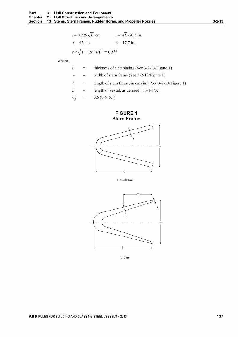
Part 3 Hull Construction and Equipment Chapter 2 Hull Structures and Arrangements Section 13 Stems, Stern Frames, Rudder Horns, and Propeller Nozzles 3-2-13
ABS RULES FOR BUILDING AND CLASSING STEEL VESSELS . 2013 137
t = 0.225 L cm t = L /20.5 in.
w = 45 cm w = 17.7 in.
tw2 2)/2(1 w+ = CfL1.5
where
t = thickness of side plating (See 3-2-13/Figure 1)
w = width of stern frame (See 3-2-13/Figure 1)
= length of stern frame, in cm (in.) (See 3-2-13/Figure 1)
L = length of vessel, as defined in 3-1-1/3.1
Cf = 9.6 (9.6, 0.1)
FIGURE 1 Stern Frame
a Fabricated
b Cast
t
w
w
t2
t1
/2
Part 3 Hull Construction and Equipment Chapter 2 Hull Structures and Arrangements Section 13 Stems, Stern Frames, Rudder Horns, and Propeller Nozzles 3-2-13
138 ABS RULES FOR BUILDING AND CLASSING STEEL VESSELS . 2013
3.5.2 Cast Stern Frame
The thicknesses t1, t2 and ( ) ( )2221 /21
2ww
tt+
+ for cast stern frames are to be not less than
given by the following equations:
t1 = 0.3 L cm but not less than 2.5 cm
t1 = L /15.3 in. but not less than 1.0 in.
t2 = 1.25t1
( ) ( ) 5.12221 /212
LCwwtt
c=++
where
w, , L = as defined in 3-2-13/3.5.1.
t1 = thickness of casting at end. (See 3-2-13/Figure 1)
t2 = thickness of casting at mid-length (See 3-2-13/Figure 1)
Cc = 8.4 (8.4, 0.086)
The thickness in way of butt welding to shell plating may be tapered below t1. The length of taper is to be at least three times the offset.
The castings are to be cored out to avoid large masses of thick material likely to contain defects and to maintain a relatively uniform section throughout. Suitable radii are to be provided in way of changes in section.
3.7 Stern Frames with Shoe Piece The scantlings below the boss of stern frames with shoe pieces are to be gradually increased to provide strength and stiffness in proportion to those of shoe pieces.
3.9 Scantlings Above the Propeller Boss Above the propeller boss, the scantlings are to be in accordance with 3-2-13/3.5, except that in the upper part of the propeller aperture, where the hull form is full and centerline supports are provided, the thickness may be reduced to 80% of the requirements in 3-2-13/3.5, subject to the same minimum for a cast steel stern frame.
3.11 Secondary Members Where round bars are used at the after edge of stern frames, their scantlings and connection details are to be such as will accomplish acceptable welding.
Ribs or horizontal brackets of thickness not less than 0.8t or 0.8t1 are to be provided at suitable intervals. Where t or t1 is reduced in accordance with 3-2-13/3.9, a proportionate reduction in the thickness of ribs or horizontal brackets may be made.
3.13 Shoe Pieces (1993) The equivalent stress σe in the shoe piece at any section is not to exceed 115/Kg N/mm2 (11.7/Kg kgf/mm2, 16700/Kg psi) and is to be obtained from the following equation:
22 3τσσ += be n N/mm2 (kgf/mm2, psi)
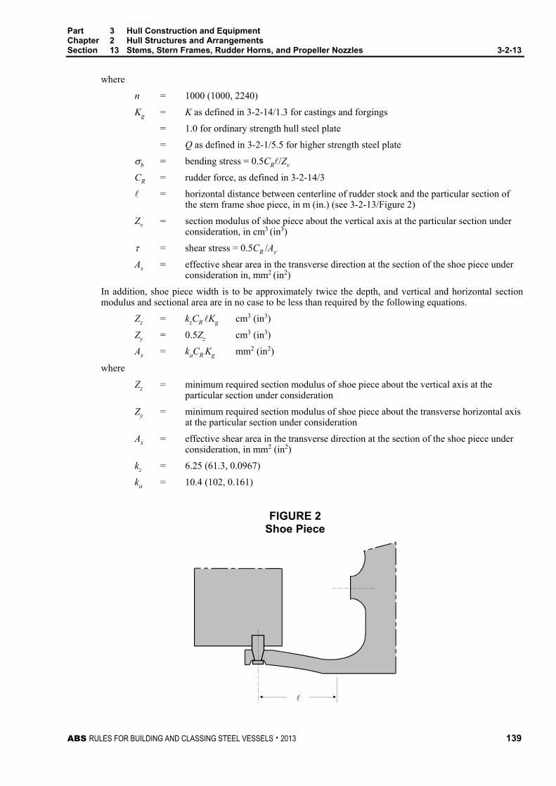
Part 3 Hull Construction and Equipment Chapter 2 Hull Structures and Arrangements Section 13 Stems, Stern Frames, Rudder Horns, and Propeller Nozzles 3-2-13
ABS RULES FOR BUILDING AND CLASSING STEEL VESSELS . 2013 139
where
n = 1000 (1000, 2240)
Kg = K as defined in 3-2-14/1.3 for castings and forgings
= 1.0 for ordinary strength hull steel plate
= Q as defined in 3-2-1/5.5 for higher strength steel plate
b = bending stress = 0.5CR/Zv
CR = rudder force, as defined in 3-2-14/3
= horizontal distance between centerline of rudder stock and the particular section of the stern frame shoe piece, in m (in.) (see 3-2-13/Figure 2)
Zv = section modulus of shoe piece about the vertical axis at the particular section under consideration, in cm3 (in3)
= shear stress = 0.5CR /As.
As = effective shear area in the transverse direction at the section of the shoe piece under consideration in, mm2 (in2)
In addition, shoe piece width is to be approximately twice the depth, and vertical and horizontal section modulus and sectional area are in no case to be less than required by the following equations.
Zz = kzCR Kg cm3 (in3)
Zy = 0.5Zz cm3 (in3)
As = kaCR Kg mm2 (in2)
where
Zz = minimum required section modulus of shoe piece about the vertical axis at the particular section under consideration
Zy = minimum required section modulus of shoe piece about the transverse horizontal axis at the particular section under consideration
As = effective shear area in the transverse direction at the section of the shoe piece under consideration, in mm2 (in2)
kz = 6.25 (61.3, 0.0967)
ka = 10.4 (102, 0.161)
FIGURE 2 Shoe Piece

Part 3 Hull Construction and Equipment Chapter 2 Hull Structures and Arrangements Section 13 Stems, Stern Frames, Rudder Horns, and Propeller Nozzles 3-2-13
140 ABS RULES FOR BUILDING AND CLASSING STEEL VESSELS . 2013
5 Rudder Horns
5.1 Scantlings – Single Pintle Rudders (1993) The strength of the rudder horn is to be based on the most critical location at any point up to and in way of the connection into the hull. At no section is the equivalent stress σe in the rudder horn to exceed 120/Kh N/mm2 (12.2/Kh kgf/mm2, 17400/Kh psi) where σe is obtained from the following equation:
σe = n )(3 222Tb ττσ ++ N/mm2 (kgf/mm2, psi)
where
n = 1000 (1000, 2240)
σb = bending stress = CR av/(pSM)
τ = shear stress due to bending = CR a/(pAh)
τT = shear stress due to torque = 0.5CR ah/(pat)
CR = rudder force, as defined in 3-2-14/3
a = vertical distance, in m (ft), from the center of the neck bearing to the centroid of A (see 3-2-13/Figure 3a)
p = vertical distance, in m (ft), from the center of the neck bearing to the center of the pintle bearing (see 3-2-13/Figure 3a)
v = vertical distance, in m (in.), from the center of the pintle bearing to the section of the rudder horn being considered (see 3-2-13/Figure 3a)
h = horizontal distance in, mm (in.), from the center of the pintle bearing to the center of area of the horizontal plane of the rudder horn at the section of the rudder horn being considered (see 3-2-13/Figure 3a)
SM = section modulus of the rudder horn about the longitudinal axis, in cm3 (in3), at the section of the rudder horn being considered
Ah = effective shear area of the rudder horn in the transverse direction at the section being considered, in mm2 (in2)
a = area, in mm2 (in2), enclosed by the outside lines of the rudder horn at the section of the rudder horn being considered
t = minimum wall thickness of the rudder horn, in mm (in.), at the section being considered
Kh = K as defined in 3-2-14/1.3 for castings and forgings
= 1.0 for ordinary strength hull steel plate
= Q as defined in 3-2-1/5.5 for higher strength steel plate
In addition to meeting the above maximum equivalent stress criteria, the shear stress is not to be greater than τ indicated in the following equation.
τ = 48/Kh N/mm2 (4.9/Kh kgf/mm2, 6960/Kh psi)
Also, the section modulus about the longitudinal horizontal axis is not to be less than given in the following equation:
SM = nzCR (a /p)vKh cm3 (in3)
nz = 14.9 (146.4, 0.230)
Webs extending down into the horn as far as practicable are to be fitted and effectively connected to the plate floors in the after peak. At the shell, the change in section of the horn is to be as gradual as possible. Generous radii are to be provided at abrupt changes of section where there are stress concentrations.

Part 3 Hull Construction and Equipment Chapter 2 Hull Structures and Arrangements Section 13 Stems, Stern Frames, Rudder Horns, and Propeller Nozzles 3-2-13
ABS RULES FOR BUILDING AND CLASSING STEEL VESSELS . 2013 141
5.3 Scantlings – Two Pintle Rudders (1993) The strength of the rudder horn is to meet the requirements for single pintle horns given in 3-2-13/5.1 above, with the following modified definitions of lever arm and component stresses.
a = vertical distance, in m (ft), from the center of the upper pintle to the centroid of A (see 3-2-13/Figure 3b)
p = vertical distance, in m (ft), from the center of the upper pintle bearing to the center of the lower pintle bearing (see 3-2-13/Figure 3b)
v = vertical distance, in m (in.), from the center of the lower pintle bearing to the section of the rudder horn being considered up to the entry of the horn into the shell plating (see 3-2-13/Figure 3b)
h = horizontal distance, in mm (in.), from the center of the lower gudgeon to the center of area of the horizontal plane of the rudder horn at the section of the rudder horn being considered (see 3-2-13/Figure 3b)
σb = bending stress
= CR av /(pSM) between the upper and lower pintle gudgeons
= CR (v + a − p)/SM in SI or MKS units, above the upper pintle gudgeon
= CR [v + 12(a − p)]/SM in U.S. units, above the upper pintle gudgeon
τ = shear stress due to bending = CRa /(pAh) between the upper and lower pintle gudgeons
= CR /Ah above the upper gudgeon
τT = shear stress due to torque = 0.5CRah /(p a t) between the upper and lower pintle gudgeons
= 0.5CRh/(a t) above the upper gudgeon
5.5 Floors Heavy plate floors are to be fitted in way of the after face of the horn and in line with the webs required by 3-2-13/5.1 and 3-2-13/5.3. They may be required to be carried up to the first deck or flat.
5.7 Shell Plating Heavy shell plates are to be fitted in way of the heavy plate floors required by 3-2-13/5.5. Above the heavy floors, the heavy shell plates may be reduced in thickness in as gradual a manner as practicable.
5.9 Water Exclusion Rudder horns are to be provided with means for draining water, except where rudder horns are filled with an approved waterproof material, or equivalent.

Part 3 Hull Construction and Equipment Chapter 2 Hull Structures and Arrangements Section 13 Stems, Stern Frames, Rudder Horns, and Propeller Nozzles 3-2-13
142 ABS RULES FOR BUILDING AND CLASSING STEEL VESSELS . 2013
FIGURE 3 Rudder Horn (1993)
Longitudinal axis
X-X
A
AX
Neck bearing
A-A
t
a p
h
X
Line of centers ofarea of horizonal
sectionsCentroid of A
v
Centers of area ofhorizonal section
Section of rudder hornbeing considered
a) Single Pintle
a p v
h
b) Two Pintles
Centroid of A
Part 3 Hull Construction and Equipment Chapter 2 Hull Structures and Arrangements Section 13 Stems, Stern Frames, Rudder Horns, and Propeller Nozzles 3-2-13
ABS RULES FOR BUILDING AND CLASSING STEEL VESSELS . 2013 143
7 Propeller Nozzles (2009)
7.1 Application The requirements in this section are applicable for propeller nozzles with inner diameter d of 5 meters (16.4 feet) or less. Nozzles of larger inner diameter are subject to special consideration with all supporting documents and calculations submitted for review.
7.3 Design Pressure The design pressure of the nozzle is to be obtained from the following:
pd = 10-6 ⋅ c ⋅ ε ⋅
pAN N/mm2 (kgf/mm2, psi)
where
c = coefficient as indicated in 3-2-13/Table 1
ε = coefficient as indicated in 3-2-13/Table 2, but not to be taken less than 10
N = maximum shaft power, in kW (hp)
Ap = propeller disc area
= D2
4π , in m2 (ft2)
D = propeller diameter, in m (ft)
TABLE 1 Coefficient c (2009)
Propeller Zone (see 3-2-13/Figure 4)
c pd in N/mm2 pd in kgf/mm2 pd in psi
2 10.0 1.02 11.62 × 10³ 1 & 3 5.0 0.51 5.81 × 10³
4 3.5 0.36 4.067 × 10³
TABLE 2 Coefficient ε (2009)
pd in N/mm2 pd in kgf/mm2 pd in psi
ε 21 – 2 × 10⁻²
pAN 21 – 2 × 10⁻²
pAN 21 – 16 × 10-2
pAN
Part 3 Hull Construction and Equipment Chapter 2 Hull Structures and Arrangements Section 13 Stems, Stern Frames, Rudder Horns, and Propeller Nozzles 3-2-13
144 ABS RULES FOR BUILDING AND CLASSING STEEL VESSELS . 2013
7.5 Nozzle Cylinder
7.5.1 Shell Plate Thickness
The thickness of the nozzle shell plating, in mm (in.), is not to be less than:
t = to + tc, but not to be taken less than 7.5 (0.3) mm (in.)
where
to = thickness obtained from the following formula:
= cn Sp nd Kp mm (in.)
cn = coefficient as indicated in 3-2-13/Table 3
Sp = spacing of ring webs, in mm (in.)
pd = nozzle design pressure, in N/mm2 (kgf/mm2, psi), as defined in 3-2-13/7.3
tc = corrosion allowance determined by 3-2-13/Table 4
Kn = nozzle material factor as defined in 3-2-14/1.3
TABLE 3 Coefficient cn (2009)
pd in N/mm2 pd in kgf/mm2 pd in psi
cn 1.58 10-1 4.95 10-1 1.32 10-2
TABLE 4 Corrosion Allowance tc (2009)
Value of to tc mm (in.)
If to 10.0 (0.4) 1.5 (0.06)
If to > 10.0 (0.4) the lesser of b1, b2
where
b1 = 3.0 (0.12) mm (in.)
b2 =
5
/1 n
o
K
t 10-1 mm or b2 =
2.0
/1 n
o
K
t 10-1 in.
7.5.2 Internal Diaphragm Thickness
Thickness of nozzle internal ring web is not to be less than the required nozzle shell plating for Zone 3.
7.7 Nozzle Section Modulus The minimum requirement for nozzle section modulus is obtained from the following formula:
SM = d2 b Vd2 Q n cm3 (in3)
where
d = nozzle inner diameter, in m (ft)
b = nozzle length, in m (ft)

Part 3 Hull Construction and Equipment Chapter 2 Hull Structures and Arrangements Section 13 Stems, Stern Frames, Rudder Horns, and Propeller Nozzles 3-2-13
ABS RULES FOR BUILDING AND CLASSING STEEL VESSELS . 2013 145
Vd = design speed in ahead condition, in knots, as defined in 3-2-14/3.1
Q = reduction factor conditional on material type
= 1.0 for ordinary strength steel
= 0.78 for H32 strength steel
= 0.72 for H36 strength steel
= 0.68 for H40 strength steel
Q factor for steel having yield strength other than above is to be specially considered.
n = nozzle type coefficient taken equal to 0.7 (0.0012) for fixed nozzles
FIGURE 4 Propeller Nozzle Section View (2012)
b
d
Zone 1Zone 2Zone 3
Zone 4
min. (b/8)
Propeller disccenter plane
b = nozzle length
d = nozzle inner diameter
Zone 1 zone of nozzle inner skin from nozzle leading edge to the fore end of Zone 2
Zone 2 zone of nozzle inner skin in way of propeller tips with two ring webs within the zone; the length on each side of the propeller center plane is not to be less than 1/8 of the nozzle length b
Zone 3 zone of nozzle inner and outer skin covering the tail vicinity, from aft end of Zones 2 to the aft end of Zone 4
Zone 4 zone of nozzle outer skin from the leading edge to the fore end of Zone 3
7.9 Welding Requirement The inner and outer nozzle shell plating is to be welded to the internal stiffening ring webs with double continuous welds as far as practicable. Plug/slot welding is prohibited for the inner shell, but may be accepted for the outer shell plating, provided that the nozzle ring web spacing is not greater than 350 mm (13.8 in.).

Part 3 Hull Construction and Equipment Chapter 2 Hull Structures and Arrangements Section 13 Stems, Stern Frames, Rudder Horns, and Propeller Nozzles 3-2-13
146 ABS RULES FOR BUILDING AND CLASSING STEEL VESSELS . 2013
9 Inspection of Castings The location of radiographic or other subsurface inspections of large stern-frame and rudder-horn castings is to be indicated on the approved plans. See applicable parts of Part 2, Chapter 1.

ABS RULES FOR BUILDING AND CLASSING STEEL VESSELS . 2013 147
P A R T S e c t i o n 1 4 : R u d d e r s
3 C H A P T E R 2 Hull Structures and Arrangements
S E C T I O N 14 Rudders and Steering Equipment (2009)
1 General
1.1 Application Requirements specified in this Section are applicable to:
i) Ordinary profile rudders described in 3-2-14/Table 1A with rudder operating angle range from -35° to +35°.
ii) High-lift rudders described in 3-2-14/Table 1B, the rudder operating angle of which might be exceeding 35° on each side at maximum design speed.
Rudders not covered in 3-2-14/Table 1A nor in 3-2-14/Table 1B are subject to special consideration, provided that all the required calculations are prepared and submitted for review in full compliance with the requirements in this section. Rudders provided on Ice Classed vessels are subject to additional requirements specified in 6-1-4/31 or 6-1-5/41, as applicable.
1.3 Rudder and Rudder Stock Materials Rudder stocks, pintles, coupling bolts, and keys are to be of steel, in accordance with the requirements of Part 2, Chapter 1. The Surveyor need not witness material tests for coupling bolts and keys. The surfaces of rudder stocks in way of exposed bearings are to be of noncorrosive material. Material factors of castings and forgings used for the shoe piece (Kg), horn (Kh), stock (Ks), bolts (Kb), coupling flange (Kf), pintles (Kp), and nozzles (Kn) are to be obtained for their respective material from the following equation:
K = (ny/Y)e
where
ny = 235 N/mm2 (24 kgf/mm2, 34000 psi)
Y = specified minimum yield strength of the material, in N/mm2 (kgf/mm2, psi), but is not to be taken as greater than 0.7U or 450 N/mm2 (46 kgf/mm2, 65000 psi), whichever is less
U = minimum tensile strength of material used, in N/mm2 (kgf/mm2, psi)
e = 1.0 for Y ≤ 235 N/mm2 (24 kgf/mm2, 34000 psi)
= 0.75 for Y > 235 N/mm2 (24 kgf/mm2, 34000 psi)
1.5 Expected Torque The torque considered necessary to operate the rudder, in accordance with 4-3-4/21.7.1i), is to be indicated on the submitted rudder or steering gear plan. See 3-2-14/5.7 and 4-3-4/1.11.
Note that this expected torque is not the design torque for rudder scantlings.
1.7 Rudder Stops Strong and effective structural rudder stops are to be fitted. Where adequate positive mechanical stops are provided within the steering gear in accordance with 4-3-4/5.11, structural stops will not be required.

Part 3 Hull Construction and Equipment Chapter 2 Hull Structures and Arrangements Section 14 Rudders and Steering Equipment 3-2-14
148 ABS RULES FOR BUILDING AND CLASSING STEEL VESSELS . 2013
3 Rudder Design Force
3.1 Rudder Blades without Cutouts The rudder force, CR, upon which rudder scantlings are to be based is to be obtained from the following equation:
CR = nkRkckAVR2 kN (tf, Ltf)
where
n = 0.132 (0.0135, 0.00123)
kR = (b2/At + 2)/3 but not taken more than 1.33
b = mean height of rudder area, in m (ft), as determined from 3-2-14/Figure 1
At = sum of rudder blade area, A, and the area of rudder post or rudder horn within the extension of rudder profile, in m2 (ft2)
A = total projected area of rudder blade, as illustrated in 3-2-14/Figure 1 in m2 (ft2)
For steering nozzles, A is not to be taken less than 1.35 times the projected area of the nozzle.
kc = coefficient depending on rudder cross section as indicated in 3-2-14/Table 1A and 1B. For cross section differing from those in 3-2-14/Table 1A and 1B, kc is subject to special consideration.
k = coefficient as specified in 3-2-14/Table 2
VR = vessel speed, in knots
= for ahead condition VR equals Vd or Vmin, whichever is greater
= for astern condition VR equals Va, or 0.5Vd, or 0.5Vmin, whichever is greater
Vd = design speed, in knots, with vessel running ahead at the maximum continuous rated shaft rpm and at the summer load waterline
Va = maximum astern speed, in knots
Vmin = (Vd + 20)/3
3.3 Rudders Blades with Cutouts This paragraph applies to rudders with cutouts (semi-spade rudders), such that the whole blade area cannot be adequately defined by a single quadrilateral. See 3-2-14/Figure 2. Equations derived in this paragraph are based on a cutout blade with two quadrilaterals. Where more quadrilaterals are needed to define the rudder shape, similar rules apply.
The total rudder force described in 3-2-14/3.1 is applicable for rudders with cutout(s), with A being the summation of sub-quadrilaterals that make up the whole area of the rudder blade. Rudder force distribution over each quadrilateral is to be obtained from the following equations:
CR1 = CRA1 /A kN (tf, Ltf)
CR2 = CRA2 /A kN (tf, Ltf)
where
CR and A are as defined in 3-2-14/3.1.
A1 and A2 are as described in 3-2-14/Figure 2.

Part 3 Hull Construction and Equipment Chapter 2 Hull Structures and Arrangements Section 14 Rudders and Steering Equipment 3-2-14
ABS RULES FOR BUILDING AND CLASSING STEEL VESSELS . 2013 149
TABLE 1A Coefficient kc for Ordinary Rudders (2009)
Profile Type kc Ahead Condition Astern Condition
1 Single plate
1.0 1.0
2 NACA-OO GÖttingen
1.1 0.80
3 Flat side
1.1 0.90
4
Mixed (e.g., HSVA)
1.21 0.90
5 Hollow
1.35 0.90
TABLE 1B Coefficient kc for High-Lift/Performance Rudders (2009)
Profile Type kc Ahead Condition Astern Condition
1 Fish tail
(e.g., Schilling high-lift rudder)
1.4 0.8
2 Flap rudder
1.7 1.3
3
Rudder with steering nozzle
1.9 1.5

Part 3 Hull Construction and Equipment Chapter 2 Hull Structures and Arrangements Section 14 Rudders and Steering Equipment 3-2-14
150 ABS RULES FOR BUILDING AND CLASSING STEEL VESSELS . 2013
FIGURE 1 Rudder Blade without Cutouts (2009)
4
3
21
bAf
c
A
Rudder StockCenterline
z (vert)
x (fwd)
b
x3 + x2 - x1 - x42
z3 + z4 - z2 - z12b=
c=
A (see 3-2-14/3.1)
Af (see 3-2-14/5.3)
FIGURE 2 Rudder Blade with Cutouts (2009)
x6 + x3 - x4 - x72
z3 + z4 - z2 - z12b=
c1=x2 + x5 - x1 - x7
2c2=
z (vert)
x (fwd)
4
3
21
7 5
6
A1f
A2f
Rudder StockCenterline
C1
b
A1
A1f, A2f (see 3-2-14/5.5)
C2
A2
A2 (see 3-2-14/3.3)
A1 (see 3-2-14/3.3)

Part 3 Hull Construction and Equipment Chapter 2 Hull Structures and Arrangements Section 14 Rudders and Steering Equipment 3-2-14
ABS RULES FOR BUILDING AND CLASSING STEEL VESSELS . 2013 151
5 Rudder Design Torque
5.1 General The rudder design torque, QR, for rudder scantling calculations, is to be in accordance with 3-2-14/5.3 or 3-2-14/5.5 as applicable.
5.3 Rudders without Cutouts Rudder torque, QR, is to be determined from the following equation for both ahead and astern conditions:
QR = CR r kN-m (tf-m, Ltf-ft)
where
CR = rudder force as calculated in 3-2-14/3.1
r = c(α − k) but not less than 0.1c for ahead condition
c = mean breadth of rudder area as shown in 3-2-14/Figure 1, in m (ft)
α = coefficient as indicated in 3-2-14/Table 3
k = Af /A
Af = area of rudder blade situated forward of the rudder stock centerline, in m2 (ft2), as shown in 3-2-14/Figure 1
A = whole rudder area as described in 3-2-14/3.1
TABLE 2 Coefficient k (2012)
Rudder/Propeller Layout k Rudders outside propeller jet 0.8 Rudders behind a fixed propeller nozzle 1.15 Steering nozzles and azimuthing thrusters 1.15 All others 1.0
TABLE 3 Coefficient α (2009)
Rudder Position or High-lift
α Ahead Condition Astern Condition
Located behind a fixed structure, such as a rudder horn
0.25 0.55
Located where no fixed structure forward of it 0.33 0.66
High-Lift Rudders (see 3-2-14/Table 1B)
Special consideration (0.40 if unknown) Special consideration

Part 3 Hull Construction and Equipment Chapter 2 Hull Structures and Arrangements Section 14 Rudders and Steering Equipment 3-2-14
152 ABS RULES FOR BUILDING AND CLASSING STEEL VESSELS . 2013
5.5 Rudders Blades with Cutouts This paragraph refers to rudder blades with cutouts (semi-spade rudders) as defined in 3-2-14/3.3. Equations derived in this paragraph are based on a cutout blade with two quadrilaterals. Where more quadrilaterals are needed to define the rudder shape, similar rules apply.
Total rudder torque, QR, in ahead and astern conditions is to be obtained from the following equation:
QR = CR1 r1 + CR2 r2 kN-m (tf-m, Ltf-ft)
but not to be taken less than QRmin in the ahead condition
where
QRmin = 0.1CR (A1c1 + A2c2)/A
r1 = c1(α – k1 ) m (ft)
r2 = c2(α – k2 ) m (ft)
c1, c2 = mean breadth of partial area A1, A2, from 3-2-14/Figure 2
α = coefficient as indicated in 3-2-14/Table 3
k1, k2 = A1f /A1, A2f /A2 where A1f, A2f = area of rudder blade situated forward of the centerline of the rudder stock for each part of the rudder, as shown in 3-2-14/Figure 2
CR, CR1, CR2, A1, A2 are as defined in 3-2-14/3.3.
5.7 Trial Conditions Above equations for QR are intended for the design of rudders and should not be directly compared with the torque expected during the trial (see 3-2-14/1.5) or the rated torque of steering gear (see 4-3-4/1.11).
7 Rudder Stocks (2012)
7.1 Upper Rudder Stocks The upper stock is that part of the rudder stock above the neck bearing or above the top pintle, as applicable. At the upper bearing or tiller, the upper stock diameter is not to be less than obtained from the following equation:
S = Nu3
sR KQ mm (in.)
where
Nu = 42.0 (89.9, 2.39)
QR = total rudder torque, as defined in 3-2-14/5, in kN-m (tf-m, Ltf-ft)
Ks = material factor for upper rudder stock, as defined in 3-2-14/1.3
7.3 Lower Rudder Stocks In determining lower rudder stock scantlings, values of rudder design force and torque calculated in 3-2-14/3 and 3-2-14/5 are to be used. Bending moments and shear forces, as well as the reaction forces are to be determined by direct calculation and are to be submitted for review. For rudders supported by shoe pieces or rudder horns, these structures are to be included in the calculation model to account for support of the rudder body. Guidance for calculation of these values is given in Appendix 3-2-A5.
The lower rudder stock diameter is not to be less than obtained from the following equation:
S = S ( ) ( )6 2/3/41 RQM+ mm (in.)
where

Part 3 Hull Construction and Equipment Chapter 2 Hull Structures and Arrangements Section 14 Rudders and Steering Equipment 3-2-14
ABS RULES FOR BUILDING AND CLASSING STEEL VESSELS . 2013 153
S = upper stock required diameter from 3-2-14/7.1, in mm (in.)
M = bending moment at the section of the rudder stock considered, in kN-m (tf-m, Ltf-ft)
QR = rudder torque from 3-2-14/5, in kN-m (tf-m, Ltf-ft)
Above the neck bearing, a gradual transition is to be provided where there is a change in the diameter of the rudder stock.
The equivalent stress of bending and torsion, σc to be assessed from the aforementioned direct calculation in the transition is not to exceed 118 /K N/mm2 (12.0/K kgf/mm2, 17100/K lbs/in2).
σc = 22 3τσ +bK
where
K = material factor as defined in 3-2-14/1.3.
σb = 10.2M/ 3S
τt = 5.1QR/ 3S
7.5 Rudder Stock Sealing i) In rudder trunks which are open to the sea, a seal or stuffing box is to be fitted above the deepest
load waterline, to prevent water from entering the steering gear compartment and the lubricant from being washed away from the rudder carrier.
ii) Where the top of the rudder trunk is below the deepest waterline two separate stuffing boxes are to be provided.
9 Flange Couplings
9.1 General Rudder flange couplings are to comply with the following requirements:
i) Couplings are to be supported by an ample body of metal worked out from the rudder stock.
ii) The smallest distance from the edge of the bolt holes to the edge of the flange is not to be less than two-thirds of the bolt diameter.
iii) Coupling bolts are to be fitted bolts.
iv) Suitable means are to be provided for locking the nuts in place.
In addition to the above, rudder flange couplings are to meet the type-specific requirements in 3-2-14/9.3 (horizontal couplings) or 3-2-14/9.5 (vertical couplings) as applicable.
9.3 Horizontal Couplings 9.3.1 Coupling Bolts
There are to be at least six coupling bolts in horizontal couplings, and the diameter, db, of each bolt is not to be less than obtained by the following equation:
db = 0.62 ( )sbs nrKKd /3 mm (in.)
where
ds = required rudder stock diameter, S (3-2-14/7.1 ) or S (3-2-14/7.3) as applicable, in way of the coupling
n = total number of bolts in the horizontal coupling
r = mean distance, in mm (in.), of the bolt axes from the center of the bolt system
Part 3 Hull Construction and Equipment Chapter 2 Hull Structures and Arrangements Section 14 Rudders and Steering Equipment 3-2-14
154 ABS RULES FOR BUILDING AND CLASSING STEEL VESSELS . 2013
Kb = material factor for bolts, as defined in 3-2-14/1.3
Ks = material factor for stock, as defined in 3-2-14/1.3
9.3.2 Coupling Flange Coupling flange thickness is not to be less than the greater of the following equations:
tf = dbt bf KK / mm (in.)
tf = 0.9dbt mm (in.)
where
dbt = calculated bolt diameter as per 3-2-14/9.3.1 based on a number of bolts not exceeding 8
Kf = material factor for flange, as defined in 3-2-14/1.3
Kb = material factor of bolts, as defined in 3-2-14/1.3
9.5 Vertical Couplings 9.5.1 Coupling Bolts
There are to be at least eight coupling bolts in vertical couplings and the diameter of each bolt is not to be less than obtained from the following equation:
db = 0.81ds ( )sb nKK / mm (in.)
where
n = total number of bolts in the vertical coupling
ds, Kb, Ks as defined in 3-2-14/9.3.
In addition, the first moment of area, m, of the bolts about the center of the coupling is not to be less than given by the following equation:
m = 0.00043ds3 mm3 (in3)
where
ds = diameter, in mm (in.), as defined in 3-2-14/9.3
9.5.2 Coupling Flange Coupling flange thickness, tf, is not to be less than db as defined in 3-2-14/9.5.1.
11 Tapered Stock Couplings
11.1 Coupling Taper (2011) Tapered stock couplings are to comply with the following general requirements in addition to type-specific requirements given in 3-2-14/11.3 or 3-2-14/11.5 as applicable:
i) Tapered stocks, as shown in 3-2-14/Figure 3, are to be effectively secured to the rudder casting by a nut on the end.
ii) Taper length () in the casting is generally not to be less than 1.5 times the stock diameter (do) at the top of the rudder.
iii) The taper on diameter (c) is to be 1/12 to 1/8 for keyed taper couplings and 1/20 to 1/12 for couplings with hydraulic mounting/dismounting arrangements, as shown in the following table.

Part 3 Hull Construction and Equipment Chapter 2 Hull Structures and Arrangements Section 14 Rudders and Steering Equipment 3-2-14
ABS RULES FOR BUILDING AND CLASSING STEEL VESSELS . 2013 155
iv) Where mounting with an oil injection and hydraulic nut, the push-up oil pressure and the push-up length are to be specially considered upon submission of calculations.
v) Means of effective sealing are to be provided to protect against sea water ingress.
Type of Coupling Assembly c =
uo dd −
Without hydraulic mounting/dismounting 1/12 ≤ c ≤ 1/8
With hydraulic mounting/dismounting 1/20 ≤ c ≤ 1/12
FIGURE 3 Tapered Couplings (2009)
do
du
dg
dn
hn
≥
d o × 1
.5
LockingNut
a) Keyed Fitting
do
du
dg
d1
SecuringFlat Bar
b) Keyless Fitting
≥
d o × 1
.5
11.3 Keyed Fitting (2010) Where the stock is keyed, the key is to be fitted in accordance with the following:
i) The top of the keyway is to be located well below the top of the rudder.
ii) Torsional strength of the key equivalent to that of the required upper stock is to be provided.
iii) The effective shear area* of the key is not to be less than Ak, given below.
K
S
mdk Y
Yr
SA ⋅=1.5
3
where
Ak = shear area of key; mm2 (in2)
S = required upper stock diameter; mm (in.); as determined by 3-2-14/7.1
rmd = offered radius of tapered stock at mid length of the bearing surface of the key; mm (in.)

Part 3 Hull Construction and Equipment Chapter 2 Hull Structures and Arrangements Section 14 Rudders and Steering Equipment 3-2-14
156 ABS RULES FOR BUILDING AND CLASSING STEEL VESSELS . 2013
YS = specified minimum yield strength of keyway material; N/mm2 (kgf/mm2, psi)
YK = specified minimum yield strength of key material; N/mm2 (kgf/mm2, psi)
iv) In general, the key material is to be at least of equal strength to the keyway material. For keys of higher strength materials, shear and bearing areas of keys and keyways may be based on the respective material properties of the keys and the keyways, provided that compatibilities in mechanical properties of both components are fully considered. In no case, is the bearing stress of the key on the keyway to exceed 90% of the specified minimum yield strength of the keyway material.
* Note: The effective area is to be the gross area reduced by any area removed by saw cuts, set screw holes, chamfer, etc., and is to exclude the portion of the key in way of spooning of the key way.
11.5 Keyless Fitting Hydraulic and shrink fit keyless couplings are to be fitted in accordance with the following:
i) Hydraulic pressure is to be specially considered upon submittal of detailed preloading stress calculations and fitting instructions;
ii) The calculated torsional holding capacity is to be at least 2.0 times the transmitted torque based on the steering gear relief valve setting;
iii) Preload stress is not to exceed 70% of the minimum yield strength of either the stock or the bore;
iv) Prior to applying hydraulic pressure, at least 75% of theoretical contact area of rudder stock and rudder bore is to be achieved in an evenly distributed manner;
v) The upper edge of the upper main piece bore is to have a slight radius;
vi) The locking nut is to be fitted in accordance with 3-2-14/11.7.
11.7 Locking Nut Dimensions of the securing nut, as shown in 3-2-14/Figure 3, are to be proportioned in accordance with the following and the nut is to be fitted with an effective locking device.
Height hn ≥ 0.6dg
Outer diameter of nut dn ≥ 1.2du or 1.5dg whichever is greater
External thread diameter dg ≥ 0.65do
In the case of a hydraulic pressure secured nut, a securing device such as a securing flat bar is to be provided. Calculations proving the effectiveness of the securing device are to be submitted.
13 Pintles
13.1 General Pintles are to have a conical attachment to the gudgeons with a taper on diameter of:
1/12 to 1/8 for keyed and other manually assembled pintles with locking nut.
1/20 to 1/12 for pintle mounted with oil injection and hydraulic nut.
The diameter of the pintles is not to be less than obtained from the following equation.
dp = k1 pBK mm (in.)
where
k1 = 11.1 (34.7, 1.38)
B = bearing force, in kN (tf, Ltf), from submitted direct calculation but not to be taken less than Bmin as specified in 3-2-14/Table 4

Part 3 Hull Construction and Equipment Chapter 2 Hull Structures and Arrangements Section 14 Rudders and Steering Equipment 3-2-14
ABS RULES FOR BUILDING AND CLASSING STEEL VESSELS . 2013 157
TABLE 4 Minimum Bearing Force Bmin (2009)
Pintle Type Bmin
Conventional two pintle rudder 0.5 CR
3-2-A5/Figure 2 lower pintle 0.5 CR
3-2-A5/Figure 3 main pintle CRa/p*
3-2-13/Figure 3 main pintle CRa/p*
upper pintle 0.25 CR * Bmin = CR where a/p ≥ 1
a, p as described in 3-2-13/Figure 3
Kp = material factor for the pintle, as defined in 3-2-14/1.3
Threads and nuts are to be in accordance with 3-2-14/11.7.
The depth of the pintle boss is not to be less than dp. In addition, the bearing length of the pintle is to be between 1.0 and 1.2 times the pintle diameter. The bearing pressure is to be in accordance with 3-2-14/15.1.
For rudders on horns with two pintles, as shown in 3-2-13/Figure 3b, calculations are to include pintle bearing forces with the vessel running ahead at the maximum continuous rated shaft rpm and at the lightest operating draft.
15 Supporting and Anti-Lifting Arrangements
15.1 Bearings (2012) 15.1.1 Bearing Surfaces
Bearing surfaces for rudder stocks, shafts and pintles are to meet the following requirements:
i) The length/diameter ratio (b/d) of the bearing surface is not to be greater than 1.2*
ii) The projected area of the bearing surface (Ab = d b) is not to be less than Abmin,
where
d = outer diameter of the liner, in mm (in.)
b = bearing length, in mm (in.)
Abmin = k1ap
P mm2 (in2)
k1 = 1000 (2240)
P = bearing reaction force, in kN (tf, Ltf), as specified in 3-2-14/Table 5
pa = allowable surface pressure, as indicated in 3-2-14/Table 6 depending on bearing material, in N/mm2 (kgf/mm2, psi)
* Request for bearing arrangement of length/diameter ratio greater than 1.2 is subject to special consideration provided that calculations are submitted to show acceptable clearance at both ends of the bearing.
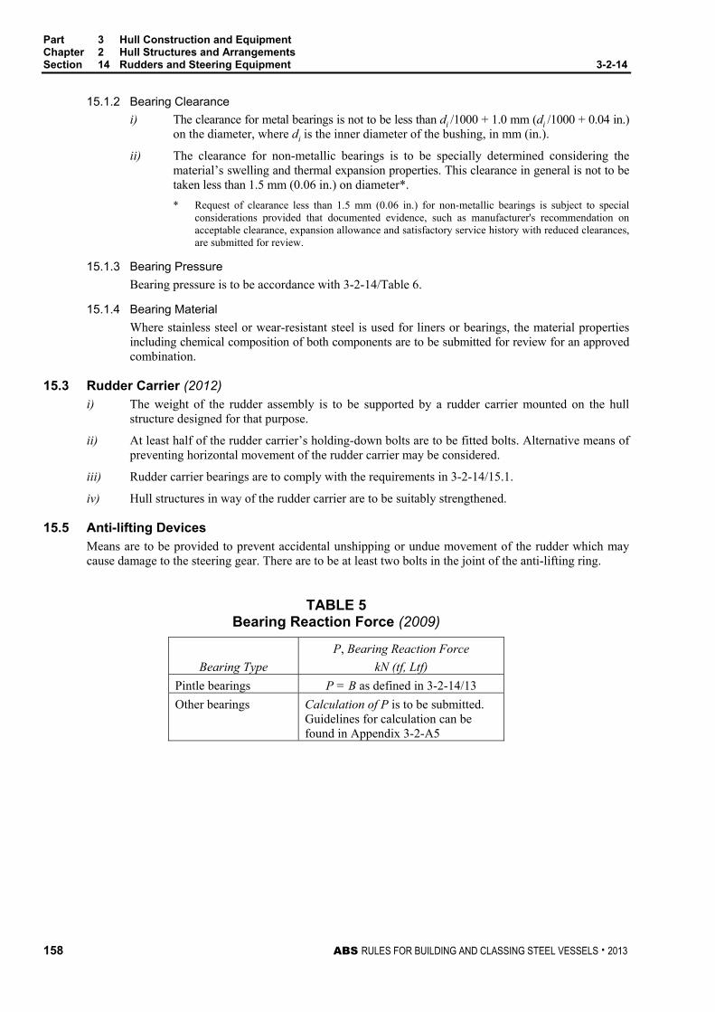
Part 3 Hull Construction and Equipment Chapter 2 Hull Structures and Arrangements Section 14 Rudders and Steering Equipment 3-2-14
158 ABS RULES FOR BUILDING AND CLASSING STEEL VESSELS . 2013
15.1.2 Bearing Clearance
i) The clearance for metal bearings is not to be less than di /1000 + 1.0 mm (di /1000 + 0.04 in.) on the diameter, where di is the inner diameter of the bushing, in mm (in.).
ii) The clearance for non-metallic bearings is to be specially determined considering the material’s swelling and thermal expansion properties. This clearance in general is not to be taken less than 1.5 mm (0.06 in.) on diameter*.
* Request of clearance less than 1.5 mm (0.06 in.) for non-metallic bearings is subject to special considerations provided that documented evidence, such as manufacturer's recommendation on acceptable clearance, expansion allowance and satisfactory service history with reduced clearances, are submitted for review.
15.1.3 Bearing Pressure
Bearing pressure is to be accordance with 3-2-14/Table 6.
15.1.4 Bearing Material
Where stainless steel or wear-resistant steel is used for liners or bearings, the material properties including chemical composition of both components are to be submitted for review for an approved combination.
15.3 Rudder Carrier (2012) i) The weight of the rudder assembly is to be supported by a rudder carrier mounted on the hull
structure designed for that purpose.
ii) At least half of the rudder carrier’s holding-down bolts are to be fitted bolts. Alternative means of preventing horizontal movement of the rudder carrier may be considered.
iii) Rudder carrier bearings are to comply with the requirements in 3-2-14/15.1.
iv) Hull structures in way of the rudder carrier are to be suitably strengthened.
15.5 Anti-lifting Devices Means are to be provided to prevent accidental unshipping or undue movement of the rudder which may cause damage to the steering gear. There are to be at least two bolts in the joint of the anti-lifting ring.
TABLE 5 Bearing Reaction Force (2009)
P, Bearing Reaction Force
Bearing Type kN (tf, Ltf)
Pintle bearings P = B as defined in 3-2-14/13
Other bearings Calculation of P is to be submitted. Guidelines for calculation can be found in Appendix 3-2-A5

Part 3 Hull Construction and Equipment Chapter 2 Hull Structures and Arrangements Section 14 Rudders and Steering Equipment 3-2-14
ABS RULES FOR BUILDING AND CLASSING STEEL VESSELS . 2013 159
TABLE 6 Allowable Bearing Surface Pressure (2012)
pa † Bearing Material N/mm2 kgf/mm2 psi lignum vitae 2.5 0.25 360 white metal, oil lubricated 4.5 0.46 650 synthetic material with hardness between 60 and 70 Shore D *
5.5 0.56 800
steel § and bronze and hot-pressed 7.0 0.71 1000 bronze-graphite materials § Stainless and wear-resistant steel in an approved combination with stock liner. † Higher values than given in the table may be taken if they are verified by tests. * Indentation hardness test at 23°C and with 50% moisture, according to a
recognized standard. Synthetic bearing materials to be of approved type.
17 Double Plate Rudder
17.1 Strength Rudder section modulus and web area are to be such that stresses indicated in the following Subparagraphs are not exceeded.
In calculating the section modulus of the rudder, the effective width of side plating is to be taken as not greater than twice the athwartship dimension of the rudder. Welded or bolted cover plates on access openings to pintles are not to be considered effective in determining the section modulus of the rudder. Generous radii are to be provided at abrupt changes in section where there are stress concentrations, including in way of openings and cover plates.
Moments, shear forces and reaction forces are to be obtained by direct calculation, which is to be submitted. Guidance for calculation of these values is given in Appendix 3-2-A5.
17.1.1 Clear of Cutouts Allowable stresses for determining the rudder strength clear of cutouts are as follows:
Bending stress σb = Kσ/Q N/mm2 (kgf /mm2, psi)
Shear stress τ = Kτ/Q N/mm2 (kgf /mm2, psi)
Equivalent stress σe = 22 3τσ +b = Ke/Q N/mm2 (kgf/mm2, psi)
where
SI units MKS units US units Kσ 110 11.2 15,900
Kτ 50 5.1 7,300
Ke 120 12.2 17,400
Q = 1.0 for ordinary strength hull steel
= as defined in 3-2-1/5.5 for higher strength steel plate

Part 3 Hull Construction and Equipment Chapter 2 Hull Structures and Arrangements Section 14 Rudders and Steering Equipment 3-2-14
160 ABS RULES FOR BUILDING AND CLASSING STEEL VESSELS . 2013
17.1.2 In way of Cutouts Allowable stresses for determining the rudder strength in way of cutouts (see 3-2-14/Figure 4) are as follows:
Bending stress σb = Kσ/Q N/mm2 (kgf/mm2, psi)
Shear stress τ = Kτ/Q N/mm2 (kgf/mm2, psi)
Equivalent stress σe = 22 3τσ +b = Ke/Q N/mm2 (kgf/mm2, psi)
where
SI units MKS units US units Kσ 75 7.65 10,900
Kτ 50 5.1 7,300
Ke 100 10.2 14,500
Q = 1.0 for ordinary strength hull steel
= as defined in 3-2-1/5.5 for higher strength steel plate
FIGURE 4
Z
6r2
6r1
6r1
r26r2
XNote:r1 = corner radius of rudder plate in way of portable bolted inspection holer2 = corner radius of rudder plate
In w
ay o
f cut
outs
r1
For spade rudders and rudders with horns, the section modulus at the bottom of the rudder is not to be less than one-third the required section modulus of the rudder at the top of the rudder or at the center of the lowest pintle.
Where rudders have an unsymmetrical foil section (e.g., reaction rudder) details of the rudder are to be submitted.
Special attention is to be paid in design and construction of rudders with slender foil sections in the vicinity of their trailing edge (e.g., hollow foil sections, fishtail foil sections). Where the width of the rudder blade at the aftermost vertical diaphragm is equal or less than 1/6 of the trailing edge length measured between the diaphragm and the trailing edge, vibration analysis of the rudder blade is also to be submitted for review.

Part 3 Hull Construction and Equipment Chapter 2 Hull Structures and Arrangements Section 14 Rudders and Steering Equipment 3-2-14
ABS RULES FOR BUILDING AND CLASSING STEEL VESSELS . 2013 161
17.3 Side, Top and Bottom Plating The plating thickness is not to be less than obtained from the following equation:
t = 0.0055sβ ( )ACkdk R /21 + × Q + k3 mm (in.)
where
Q = 1.0 for ordinary strength hull steel
= as defined in 3-2-1/5.5 for higher strength steel plate
k1 = 1.0 (1.0, 0.305)
k2 = 0.1 (0.981, 10.7)
k3 = 2.5 (2.5, 0.1)
d = summer loadline draft of the vessel, in m (ft)
CR = rudder force according to 3-2-14/3, in kN (tf, Ltf)
A = rudder area, in m2 (ft2)
β = ( )2/5.01.1 bs− maximum 1.0 for b/s ≥ 2.5
s = smaller unsupported dimension of plating, in mm (in.)
b = greater unsupported dimension of plating, in mm (in.)
The thickness of the rudder side or bottom plating is to be at least 2 mm (0.08 in.) greater than that required by 3-2-10/3.1 for deep tank plating in association with a head h measured to the summer load line.
17.5 Diaphragm Plates Vertical and horizontal diaphragms are to be fitted within the rudder, effectively attached to each other and to the side plating. Vertical diaphragms are to be spaced approximately 1.5 times the spacing of horizontal diaphragms.
The thickness of diaphragm plates is not to be less than 70% of the required rudder side plate thickness or 8 mm (0.31 in.), whichever is greater. Openings in diaphragms are not to exceed one half their depth.
Welding is to be in accordance with Section 2-4-1 and Section 3-2-19. Where inaccessible for welding inside the rudder, it is recommended that diaphragms be fitted with flat bars and the side plating be connected to these flat bars by continuous welds or by 75 mm (3 in.) slot welds spaced at 150 mm (6 in.) centers. The slots are to be fillet welded around the edges and filled with a suitable compound.
17.7 Watertightness The rudder is to be watertight and is to be tested in accordance with 3-7-1/Table 1.
19 Single Plate Rudders
19.1 Mainpiece Diameter The mainpiece diameter is calculated according to 3-2-14/7.3. For spade rudders, the lower third may be tapered down to 0.75 times stock diameter at the bottom of the rudder.

Part 3 Hull Construction and Equipment Chapter 2 Hull Structures and Arrangements Section 14 Rudders and Steering Equipment 3-2-14
162 ABS RULES FOR BUILDING AND CLASSING STEEL VESSELS . 2013
19.3 Blade Thickness The blade thickness is not to be less than obtained from the following equation:
tb = 0.0015sVR + 2.5 mm
tb = 0.0015sVR + 0.1 in.
where
s = spacing of stiffening arms, in mm (in.), not to exceed 1000 mm (39 in.)
VR = speed, as defined in 3-2-14/3
19.5 Arms The thickness of the arms is not to be less than the blade thickness obtained in 3-2-14/19.3. The section modulus of each set of arms about the axis of the rudder stock is not to be less than obtained from the following equation:
SM = 0.0005sC12VR
2Q cm3
SM = 0.0000719sC12VR
2Q in3
where
Cl = horizontal distance from the aft edge of the rudder to the centerline of the rudder stock, in m (ft)
Q = 1.0 for ordinary strength hull steel
= as defined in 3-2-1/5.5 for higher strength steel plate
s, VR are as defined in section 3-2-14/21.3.
21 Steering Nozzles (2012)
21.1 Application Scope Requirements in this Subsection are applicable to conventional steering nozzles, as illustrated in 3-2-14/Figure 5, with the following restrictions:
i) The inner diameter of 5 meters (16.4 feet) or less, and
ii) The operating angle ranging not more than –35° to +35° port and starboard
iii) Nozzles of above features but provided on the vessels for Ice Class are subject to additional requirements specified in Part 6, as applicable
Steering nozzles outside of the application scope are subject to special consideration with all supporting documents and calculations submitted to ABS for review. The submitted documents and calculations are to include, but not limited to, the items listed in the following:
i) The drawings and plans of steering nozzle with indications of design operating angles and the torque considered necessary to operate the steering nozzle at the design operating angle
ii) The calculated steering nozzle section modulus
iii) The calculated maximum water induced pressure of the nozzle under design speed (both ahead and astern conditions) and at the design operating angle, and
iv) The calculated maximum shear and bending of nozzle support structure under design speed (both ahead and astern conditions) and at the design operating angle

Part 3 Hull Construction and Equipment Chapter 2 Hull Structures and Arrangements Section 14 Rudders and Steering Equipment 3-2-14
ABS RULES FOR BUILDING AND CLASSING STEEL VESSELS . 2013 163
21.3 Design Force The design force, CR, for steering nozzles is to be obtained from the following equation:
CR = nkRkck AVR2 kN (tf, Ltf)
where
kR = (dm2/At + 2)/3 but not taken more than 2
dm = mean external diameter of the nozzle, in m (ft)
= 0.5(df + da)
df , da = fore and aft nozzle external diameters as shown in 3-2-14/Figure 5, in m (ft)
At = Aeq+Apo+Amf, in m2 (ft2)
Aeq = nominal projected area of nozzle cylinder, not to be taken less than 1.35dmb
b = nozzle length in m (ft)
Apo = projected area of nozzle post or horn within the extension of nozzle profile as applicable
Amf = projected area of movable flap if present
= da bmf
A = Aeq+ Amf, in m2 (ft2)
kc = 1.9 for ahead condition
= 1.5 for astern condition
k = 1.15, as specified in 3-2-14/Table 2
n, VR are as defined in 3-2-14/3.1.
FIGURE 5 Nozzle Geometry (2012)
da dfdc
bmf ba bf
b

Part 3 Hull Construction and Equipment Chapter 2 Hull Structures and Arrangements Section 14 Rudders and Steering Equipment 3-2-14
164 ABS RULES FOR BUILDING AND CLASSING STEEL VESSELS . 2013
21.5 Design Torque Design torque, QR, for steering nozzle is to be determined from the following equation for both ahead and astern conditions:
QR = CR r kN-m (tf-m, Ltf-ft)
where
r = (α − k), but not less than 0.1 for ahead condition
= b without flap, in m (ft)
= b + bmf if flap present
k = Af /A
Af = Aeq bf /, in m2 (ft2)
dc = nozzle diameter at the section intersecting with nozzle stock axis;
α is as defined in 3-2-14/Table 3.
A, CR are as defined in 3-2-14/21.3.
21.7 Nozzle Stock 21.7.1 Upper Stock
The upper stock is that part of the nozzle stock above the neck bearing.
At the upper bearing or tiller, the upper stock diameter is not to be less than obtained from the following equation:
S = Nu3
sR KQ mm (in.)
where
Nu = 42.0 (823.9, 2.39)
QR = as defined in 3-2-14/21.5
Ks = material factor for nozzle stock, as defined in 3-2-14/1.3
21.7.2 Lower Stock In determining lower stock diameters, values of nozzle design force and torque calculated in 3-2-14/21.3 and 3-2-14/21.5 are to be used. Bending moments and shear forces, as well as the reaction forces are to be determined by direct calculation and are to be submitted for review. For nozzles supported by shoe pieces, these structures are to be included in the calculation. Calculation guidance for these values is given in Appendix 3-2-A5.
The lower nozzle stock diameter is not to be less than obtained from the following equation:
S = S ( )6 2/3/41 RQM+ mm (in.)
where
S = required upper stock diameter from 3-2-14/21.7.1, in mm (in.)
M = bending moment at the cross section of the nozzle stock considered, in kN-m (tf-m, Ltf-ft)
QR = design torque obtained from 3-2-14/21.5, in kN-m (tf-m, Ltf-ft)
Where there is a change in stock diameter above the neck bearing, a gradual transition is to be provided.

Part 3 Hull Construction and Equipment Chapter 2 Hull Structures and Arrangements Section 14 Rudders and Steering Equipment 3-2-14
ABS RULES FOR BUILDING AND CLASSING STEEL VESSELS . 2013 165
21.9 Design Pressure The design pressure of the nozzle is to be obtained from the following:
p = pd + ps N/mm2 (kgf/mm2, psi)
where
ps = cs CR/A
cs = 0.001 (0.0001, 0.145)
CR, A as defined in 3-2-14/21.3
pd as defined in 3-2-13/7.3
21.11 Plate Thickness 21.11.1 Nozzle Shell
The thickness of the nozzle shell plating, in mm (in.), is not to be less than:
t = to + tc mm (in.), but not to be taken less than 7.5 mm (0.3 in.)
where
to = thickness obtained from the following formula:
= cn⋅Sp⋅ npK mm (in.)
cn = coefficient as indicated in 3-2-13/Table 3
Sp = spacing of ring webs, in mm (in.)
p = design pressure, in N/mm2 (kgf/mm2, psi), as defined in 3-2-14/21.9
tc = corrosion allowance determined by 3-2-13/Table 4
Kn = nozzle material factor as defined in 3-2-14/1.3
21.11.2 Internal Diaphragm Thickness of nozzle internal ring web is not to be less than the required nozzle shell plating for Zone 3 as illustrated in 3-2-13/Figure 4.
21.11.3 Movable Flap Nozzle movable flap plate thickness, if present, is to comply with the following:
i) For double-plate movable flap, requirements in 3-2-14/17 are to be satisfied as applicable;
ii) For single-plate movable flap, requirements in 3-2-14/19 are to be satisfied as applicable;
21.13 Section Modulus Steering nozzle is to have a section modulus at least equal to that specified in 3-2-13/7.7, where n is replaced by 1.0 (0.0017).
21.15 Locking Device A mechanical locking device is to be provided:
i) To prevent the steering nozzle from rotating beyond the maximum operating angle at design speed
ii) To prevent steering nozzle from rotating toward undesired directions in the event of accident or damage
21.17 Welding Requirement Steering nozzle welding procedures are to comply with 3-2-13/7.9.

Part 3 Hull Construction and Equipment Chapter 2 Hull Structures and Arrangements Section 14 Rudders and Steering Equipment 3-2-14
166 ABS RULES FOR BUILDING AND CLASSING STEEL VESSELS . 2013
23 Azimuthal Thruster (2012)
23.1 Plans and Documents The following plans and documents are to be submitted to ABS as applicable:
i) General arrangement of the thruster
ii) Structural items (nozzle, bracing, etc.)
iii) Structural connection to hull
iv) Propeller drawings
v) Bearing details
vi) Propeller and intermediate shafts
vii) Gears
viii) Rotating mechanism of the thruster
ix) Thruster control system
x) Piping systems connected to thruster
xi) Manufacturer specified/calculated maximum load on the unit for crash stop condition Note For specific requirements of machinery components, see Part 4 as applicable
23.3 Application Scope Requirements in this Subsection are applicable to Azimuthal Thrusters (also referred as integrated nozzle propellers), as illustrated in 3-2-14/Figure 6, with the following restrictions:
i) The inner diameter of thruster’s nozzle is of 5 meters (16.5 feet) or less, and
ii) Azimuthal thrusters of above features but provided on the vessels for Ice Class are subject to additional requirements specified in Part 6, as applicable
Azimuthal thrusters outside of the above application scope are subject to special consideration with all supporting documents and calculations submitted to ABS for review. The submitted documents and calculations include, but are not limited to, the following items:
i) The drawings and plans of the thruster with indications of design operating angles and the torque considered necessary to operate the thruster at the design operating angle
ii) The calculated thruster section modulus
iii) The calculated maximum water induced pressure of the thruster under design speed (both ahead and astern conditions) and at the design operating angle, and
iv) The calculated maximum shear and bending of thruster support structure under design speed (both ahead and astern conditions) and at the design operating angle
23.5 Locking Device A locking device is to be provided to prevent the azimuthal thruster from rotating toward undesired directions in the event of accident or damage.

Part 3 Hull Construction and Equipment Chapter 2 Hull Structures and Arrangements Section 14 Rudders and Steering Equipment 3-2-14
ABS RULES FOR BUILDING AND CLASSING STEEL VESSELS . 2013 167
23.7 Design Force The design force, CR, for azimuthal thrusters is the maximum load for crash stop condition (3-2-14/23.1) or as obtained from the following equation, whichever is greater:
CR = nkRkck AVR2 kN (tf, Ltf)
where
kR = (dm2/A + 2)/3 but not taken more than 1.33
dm = mean external diameter of the nozzle, in m (ft)
= 0.5(df + da)
df , da = fore and aft nozzle external diameters as shown in 3-2-14/Figure 6, in m (ft)
b = nozzle length in m (ft)
A = Aeq+Atb, in m2 (ft2)
Aeq = equivalent nominal area of nozzle cylinder, not to be taken less than 1.35dmb, in m2 (ft2)
Atb = effective projected areas of the azimuthal thruster forward of the nozzle, not to be taken less than 0.707dfdo, in m2 (ft2)
do = outer diameter of steering tube, in m (ft)
kc = 1.9 for ahead condition
= 1.5 for astern condition.
k = 1.15, as specified in 3-2-14/Table 2
n, VR are as defined in 3-2-14/3.1.
FIGURE 6 Azimuthal Thruster (2012)
da df
b
a f
do
SteeringTube
SupportStrut
Nozzle
PropellerHousing
c

Part 3 Hull Construction and Equipment Chapter 2 Hull Structures and Arrangements Section 14 Rudders and Steering Equipment 3-2-14
168 ABS RULES FOR BUILDING AND CLASSING STEEL VESSELS . 2013
23.9 Design Torque Design torque, QR, for azimuthal thruster is to be determined from the following equation for both ahead and astern conditions:
QR = CR r kN-m (tf-m, Ltf-ft)
where
r = (α − k), but not less than 0.1 for ahead condition
= length of azimuthal thruster, in m (ft)
k = Af /A
Af = effective projected area of azimuthal thrust unit forward of steering centerline (within the extent length of f), not to be taken less than 0.5 Atb, in m2 (ft2)
α is as defined in 3-2-14/Table 3.
CR and A are as defined in 3-2-14/23.7.
23.11 Design Pressure The design pressure of the nozzle is to be obtained from the following:
p = pd + ps N/mm2 (kgf/mm2, psi)
where
ps = cs CR/A N/mm2 (kgf/mm2, psi)
pd, cs are as defined in 3-2-14/21.9.
CR, A are as defined in 3-2-14/23.7.
23.13 Nozzle Scantlings 23.13.1 Nozzle Shell
The thickness of the nozzle shell plating, in mm (in.), is not to be less than the following:
t = to + tc mm (in.), but not to be taken less than 7.5 mm (0.3 in.)
where
to = cn Sp⋅ npK mm (in.)
cn = coefficient as indicated in 3-2-13/Table 3
Sp = nozzle ring web spacing, in mm (in.)
p = design pressure as defined in 3-2-14/23.11
tc = corrosion allowance determined by 3-2-13/Table 4
Kn = material factor of the nozzle, as defined in 3-2-14/1.3
23.13.2 Internal Diaphragm Thickness of nozzle internal ring webs and diaphragms are not to be less than that required by 3-2-13/7.5.2.
23.15 Steering Tube The steering tube of the azimuthal thruster is to have scantlings of at least the same strength against bending moment and shear force as an equivalent stock with diameter calculated in accordance with 3-2-14/7.
where
QR is replaced by the design torque as defined in 3-2-14/23.9
Ks is replaced by material factor of the steering tube
M is the bending moment calculated at the section of the steering tube under consideration

Part 3 Hull Construction and Equipment Chapter 2 Hull Structures and Arrangements Section 14 Rudders and Steering Equipment 3-2-14
ABS RULES FOR BUILDING AND CLASSING STEEL VESSELS . 2013 169
23.17 Section Modulus Azimuthal thruster nozzle is to have a section modulus at least equal to that specified in 3-2-13/7.7, where n is replaced by 1.1 (0.00187).
23.19 Welding Requirement Integrated nozzle welding procedures are to comply with 3-2-13/7.9 as applicable.
25 Azimuthing Pod (2012)
25.1 General Remarks The requirements presented in 3-2-14/25 apply to the scantlings of the hull supports, strut, pod body, and pod fin if present. The requirements for steering unit, bearings, and other mechanical and electrical parts are offered in Part 4.
A general illustration of azimuthing pod unit is given in 3-2-14/Figure 7, which consists of the following parts:
i) Slewing ring
ii) Hull supporting structure
iii) Strut
iv) Pod body
v) Fin (if present)
FIGURE 7 Pod Propulsion Unit (2012)
Slewing Ring
Strut
Pod Body
hD
Fin
Hull Structure

Part 3 Hull Construction and Equipment Chapter 2 Hull Structures and Arrangements Section 14 Rudders and Steering Equipment 3-2-14
170 ABS RULES FOR BUILDING AND CLASSING STEEL VESSELS . 2013
25.3 Application Scope Requirements hereafter apply to the azimuthing pod units with restrictions indicated below: i) Units powered by electric propulsion motors
ii) Maximum operating angle at the design speed not to be greater than 35° on each side
iii) Units provided on Ice Classed vessels subject to additional requirements in Part 6, Chapter 1, as applicable
iv) Units of features and specifications outside the above scope are subject to special considerations provided plans and documents specified in 3-2-14/25.5 are submitted to ABS in early design stage
25.5 Plans and Documents The following plans and documents are to be submitted to ABS:
i) System description including a block diagram showing how the various components are functionally related
ii) Ship’s maneuvering capability in the specified operating conditions
iii) Material grades, properties and welding specifications
iv) Non-destructive Testing (NDE) procedures for propulsion shaft, slewing ring bearings, gears, and couplings
v) Arrangement and scantlings in way of the pod unit and the hull supporting structure integration with the maximum loads on the structure marked
vi) Arrangements and scantlings of strut, pod body, fin (if present), and bearing mounting, also showing internal structures and assembly
vii) Drawings of detailed structural connection between structural components (i.e., bolted connections)
viii) Design loads for azimuthing pod, hull supporting structure, and propeller under all the specified design operating conditions
ix) Rated power, revolutions, and thrust
x) Power transmitted at the maximum torque condition
xi) Vibration analysis covering all operating speeds as specified in 4-3-7/1.7.3
xii) Maximum transient thrust, torque and other forces and moments experienced during all foreseeable operating modes permitted by the steering and propulsor drive control systems
xiii) Details of steering securing/locking (as specified in 3-2-14/25.9) and details of propeller shaft
xiv) Drawings of bearing arrangements with calculations of maximum bearing pressure and bearing lifetime calculation
xv) Manufacturer’s limits on the seating flatness of the slewing ring
xvi) Thruster force calculations and predicted polar plots
xvii) Calculations of maximum hydrodynamic response to ship motions and accelerations, slamming, and pod/hull interaction for all the anticipated seagoing and operating conditions
xviii) Design loads for both the pod structure and propeller together with podded propulsion unit design operating modes
xix) Failure Modes and Effects Analysis (FMEA) or other equivalent risk analysis to demonstrate a single failure does not lead to total loss of all propulsion and/or steering capability
xx) The maximum anticipated loads calculated according to 3-2-14/25.11
xxi) Fatigue analysis for local structure connections may be required

Part 3 Hull Construction and Equipment Chapter 2 Hull Structures and Arrangements Section 14 Rudders and Steering Equipment 3-2-14
ABS RULES FOR BUILDING AND CLASSING STEEL VESSELS . 2013 171
xxii) Cooling system’s piping system schematic
xxiii) Details of installed condition monitoring equipment
xxiv) Detailed list of hazardous atmospheric conditions including the maximum air temperature of inside the pod
xxv) Drawings of access and closing arrangements for pod unit inspection and maintenance
Note For specific requirements of machinery components, refer to Part 4 as applicable
25.7 Material Requirements i) Azimuthing pod units are to be of steels manufactured, tested, and certificated in accordance with
ABS Rules for Materials and Welding (Part 2).
ii) Steels of specified tensile strength greater than 950 N/mm2 (98.9 kgf/mm2, 137,786 psi) or hardness of greater than 30 HRC are not to be used for pod fasteners at risk of coming in contacting with seawater.
iii) Material factors for local structure/component are to be obtained according to 3-2-14/1.3.
25.9 Locking Device A mechanical locking device is to be provided for the azimuthing pod:
i) To prevent azimuthing pod from rotating beyond the maximum operating angle at design speed to limit the maximum torque the system is subjected to
ii) To prevent azimuthing pod from rotating toward undesired directions in the event of accident or damage
iii) To keep each pod unit’s slewing mechanism in its center (neutral) position in the event of steering system failure where more than one pod units are installed
iv) To keep the pod in position at the vessel’s maneuvering speed of not less than 7 knots
25.11 Direct Analysis The scantlings of the azimuth propulsion system and the associated hull supports are to be determined by the maximum pressure and loads obtained through direct calculations. The maximum anticipated service loads are to be determined by recognized acceptable methods, which include at least the following:
i) Gravity and buoyancy
ii) Forces of lift, drag, and thrust
iii) Maximum combined heave and pitch motions in way of hull and azimuthing pod interface
iv) Pod operates at maximum angle on each side while the ship travels at design speed
v) Maximum loads calculated for the crash stop obtained through a 180° rotation of the pod.
vi) Maximum loads calculated for the possible orientations of the system greater than the maximum angle at the relevant speed
vii) Any maneuvering conditions that are likely to give rise to high mean or vibratory loadings induced by the podded propulsion unit.
viii) Stern slamming pressure at speeds of 0 and 5 knots for all wave heights, following sea to beam sea.
ix) Rapid acceleration and deceleration maneuvers demands per the ship's operating manual.
x) The condition where the vessel travels ahead in a steady course under design oceangoing conditions while the azimuthing pod at its the maximum rated output.
Hydrodynamic analysis is to be carried out such that the structural response under the most severe load combination is not to exceed the normal operational requirements of the propulsion or steering system.
Finite element analysis is to be carried out to evaluate the structural design. The FE model developed for use with the stress criteria in 3-2-14/Table 7 should be discussed and agreed with ABS before analysis is commenced.

Part 3 Hull Construction and Equipment Chapter 2 Hull Structures and Arrangements Section 14 Rudders and Steering Equipment 3-2-14
172 ABS RULES FOR BUILDING AND CLASSING STEEL VESSELS . 2013
25.13 Strength Criteria The maximum stress on the strut, pod body, and hull structure obtained from the direct analysis according to 3-2-14/25.11 is to satisfy the strength checking criteria described in 3-2-14/Table 7.
Structure components showing localized stress concentration that is greater than the allowable stress indicated in 3-2-14/Table 7 may be accepted on a case by case basis, depending on the location and the scale of the localized stress, as well as the type of analysis or modeling criteria is used.
TABLE 7 Permissible Stress Values (2012)
Location Pod Structure Hull Structure and Pod/Hull Interface
Shear stress 0.21σF 0.44σF Bending stress 0.47σF 0.59σF Von Mises stress 0.51σF 0.85σF Localized Von Mises stresses (peak stresses) σF σF
Note: σF = yield stress of local material
25.15 Additional Requirements Azimuthing pod and hull support primary structure having the calculated maximum stress not exceeding the values given in 3-2-14/Table 7 are subject to additional scantling requirements in the following sections.
25.15.1 Pod Strut The pod strut is to have scantlings that meet the following requirements. Similar requirements also apply to the scantlings for pod fin, as applicable.
25.15.1(a) Strut Shell Plating. The plating thickness is not to be less than obtained from the following:
t = 0.0055sβ max2max1 pkdk + × K + k3 mm (in.)
where
s = smaller unsupported dimension of plating, in mm (in.)
β = ( )2/5.01.1 bs− maximum 1.0 for b/s ≥ 2.5
b = greater unsupported dimension of plating, in mm (in.)
k1 = 1.0 (1.0, 0.305)
k2 = 0.1 (0.981, 10.7)
k3 = 2.5 (2.5, 0.1)
dmax = vessel’s maximum permissible draft in m (ft), but not be taken less than 6.1 m (20 ft)
pmax = maximum pressure obtained from direct calculation
K = plating material factor as defined in 3-2-14/1.3, as applicable
= 1.0 for ordinary strength steel plate
25.15.1(b) Strut Strength. Strut section modulus and web area are to be such that stresses indicated in 3-2-14/25.13, as applicable, are not exceeded.

Part 3 Hull Construction and Equipment Chapter 2 Hull Structures and Arrangements Section 14 Rudders and Steering Equipment 3-2-14
ABS RULES FOR BUILDING AND CLASSING STEEL VESSELS . 2013 173
25.15.1(c) Strut Diaphragm. Strut internal diaphragms are to be fitted such that:
i) Vertical and horizontal diaphragms of strut are to be effectively attached to each other and to the shell plating. In addition, the vertical diaphragms are to be spaced approximately 1.5 times the spacing of horizontal diaphragms.
ii) The thickness of strut internal diaphragm is not to be less than 70% of the required shell plate thickness or 8 mm (0.31 in.), whichever is greater.
iii) Openings in strut diaphragms are not to exceed one half their depths.
iv) Where diaphragms are inaccessible for welding, they are to be fitted with flat bars connecting to the side plating by continuous welds or by 75 mm (3 in.) slot welds spaced at 150 mm (6 in.) centers. The slots are to be fillet welded around the edges and filled with a suitable compound.
25.15.2 Pod Body The minimum scantlings of the pod structure are not to be less than obtained from the following.
25.15.2(a) Pod Shell Plating. The shell plate thickness of the pod body is not to be less than the greatest t indicated below:
t1 = 2.7r max2max1 pkdk + × K + k3 mm (in.), or
t2= sk0fc
Kh)( + to mm (in.), or
t3 = 6.5 (0.25) mm (in.), or
t4 = s/150 + to mm (in.)
where
r = mean radius of pod body
k0 = (3.075 α – 2.077)/(α + 0.272) for 1 ≤ α ≤ 2
= 1.0 for α > 2
α = aspect ratio of the panel (longer edge/shorter edge)
h = distances, in m (ft), from the lower edge of the plate to the summer load line;
cf = 254 (460)
to = 2.5 (0.1)
k1, k2, k3, d, pmax, K as defined in 3-2-14/25.15.1(a).
25.15.2(b) Pod Webs. The thickness of primary webs is not to be less than 70% of the adjacent shell plating or 10 mm, whichever is the greater.
25.15.2(c) Pod Stiffeners. The properties of the secondary stiffening are not to be less than obtained from 3-2-5/3.17 or 3-2-10/3.3, whichever is the greater.
25.15.3 Hull Support Hull supporting structure, as illustrated in 3-2-14/Figure 8, in way of azimuthing pod unit is to comply with the following:
i) Hull girders connecting the slewing ring and the ordinary hull girders and floors are, in general, to be radially arranged for even transmission of loads and moments from the pod to the rest of the hull structure without unwarranted deflection.
ii) Hull seating for the slew ring is to be sufficiently stiffened so that the flexure is within the manufacturer’s specifications for the bearing.

Part 3 Hull Construction and Equipment Chapter 2 Hull Structures and Arrangements Section 14 Rudders and Steering Equipment 3-2-14
174 ABS RULES FOR BUILDING AND CLASSING STEEL VESSELS . 2013
iii) The minimum thickness for the girders of hull support is to be in accordance with 3-2-4/3.1, as applicable.
iv) Plate buckling of hull primary support members is to be below the ideal elastic deformation limit of the material.
v) Shell plating thickness in way of hull primary support structure is to be at least 50% thicker than as required for the adjacent shell plating.
FIGURE 8 Hull Supporting Structure (2012)
Floors Slewing Ring Seating Radial Girders Longitudinal Girders
x
y
25.15.4 Slewing Bearing Calculations of bearing stress are to be submitted for review and the equivalent stresses are to be lower than 80% of the yield strength of the bearing ring seating.
25.17 Structural Transition The structural transitions of azimuthing pods are to avoid abrupt changes as much as practical. Structural transitions are to be smooth and gradual in way of the:
i) Strut from upper mounting with steering unit to the lower section
ii) Connection of strut and pod body with fillet radius not less than 75 mm (3 in.), in general
25.19 Service Accessibility Azimuthing pod internal structures and parts including webs, frames, shafts, bearings, and seal arrangements are to be accessible for surveys and examinations in accordance with Section 3-7-1 as applicable.
25.21 Air and Drainage Escape Limber and air holes are to be cut in all parts of pod internal structure as required for drainage, free flow to the section pipes and the escape of air to vents.

Part 3 Hull Construction and Equipment Chapter 2 Hull Structures and Arrangements Section 14 Rudders and Steering Equipment 3-2-14
ABS RULES FOR BUILDING AND CLASSING STEEL VESSELS . 2013 175
25.23 Watertightness Azimuthing pods are to be of watertight and are to be tested in accordance with 3-7-1/Table 1, as applicable.
25.25 Welding Requirements Welding is to be in accordance with Section 2-4-1 of the ABS Rules for Materials and Welding (Part 2) and Section 3-2-19. Where inaccessible for welding inside the pod, it is recommended that webs, frames, and diaphragms be fitted with flat bars and the side plating be connected to these flat bars by continuous welds or by 75 mm (3 in.) slot welds spaced at 150 mm (6 in.) centers. The slots are to be fillet welded around the edges and filled with a suitable compound.

176 ABS RULES FOR BUILDING AND CLASSING STEEL VESSELS . 2013
P A R T Appendix 5: Guidelines for Calculating Bending Moment and Shear Force in Rudders and Rudder Stocks
3 C H A P T E R 2 Hull Structures and Arrangements
A P P E N D I X 5 Guidelines for Calculating Bending Moment and Shear Force in Rudders and Rudder Stocks (1993)
1 Application Bending moments, shear forces and reaction forces of rudders, stocks and bearings may be calculated according to this Appendix for the types of rudders indicated. Moments and forces on rudders of different types or shapes than those shown are to be calculated using alternative methods and will be specially considered.
3 Spade Rudders
3.1 Rudder 3.1.1 Shear Force
Lateral shear force, V(z), at a horizontal section of the rudder z meters (feet) above the bottom of R is given by the following equation:
V(z) = ( )
−+
cczc
AzC
uR
R
2 kN (tf, Ltf )
where
z = distance from the bottom of R to the horizontal section under consideration, in m (ft)
CR = rudder force, as defined in 3-2-14/3, in kN (tf, Ltf)
A = rudder blade area, in m2 (ft2)
c, cu and R are dimensions as indicated in 3-2-A5/Figure 1, in m (ft).
3.1.2 Bending Moment Bending moment, M(z), at a horizontal section z meters (feet) above the baseline of the rudder is given by the following equation:
M(z) = ( )
−+
cczc
ACz
uR
R
32
2
kN-m, (tf-m, Ltf-ft)
where z, CR, A, c, cu and R are as defined in 3-2-A5/3.1.1.

Part 3 Hull Construction and Equipment Chapter 2 Hull Structures and Arrangements Appendix 5 Guidelines for Calculating Bending Moment & Shear Force in Rudders & Rudder Stocks 3-2-A5
ABS RULES FOR BUILDING AND CLASSING STEEL VESSELS . 2013 177
3.3 Lower Stock 3.3.1 Shear Force
Lateral shear force at any section of the lower stock between the top of the rudder and the neck bearing, V, is given by the following equation:
V = CR kN (tf, Ltf)
where CR is as defined in 3-2-A5/3.1.1
3.3.2 Bending Moment at Neck Bearing The bending moment in the rudder stock at the neck bearing, Mn, is given by the following equation:
Mn =
+
++
)(3)2(
u
uRR cc
ccC
kN-m (tf-m, Ltf-ft)
where
CR = rudder force as defined in 3-2-A5/3.1.1
c, cu, and R are dimensions as indicated in 3-2-A5/Figure 1, in m (ft).
3.5 Moment at Top of Upper Stock Taper The bending moment in the upper rudder stock at the top of the taper, Mt, is given by the following equation:
Mt =
−++×
+
++
u
tRu
u
uRR
zcc
ccC
)()(3
)2( kN-m (tf-m, Ltf-ft )
where
zt = distance from the rudder baseline to the top of the upper rudder stock taper in m (ft)
CR = rudder force, as defined in 3-2-A5/3.1.1
c, cu, , u and R are dimensions as indicated in 3-2-A5/Figure 1, in m (ft).
3.7 Bearing Reaction Forces Reaction forces at the bearings are given by the following equations:
Pu = reaction force at the upper bearing
= − u
nM
kN (tf, Ltf)
Pn = reaction force at the neck bearing
= CR + u
nM
kN (tf, Ltf)
where
Mn = bending moment at the neck bearing, as defined in 3-2-A5/3.3.2
CR = rudder force, as defined in 3-2-14/3
u is as indicated in 3-2-A5/Figure 1, in m (ft).

Part 3 Hull Construction and Equipment Chapter 2 Hull Structures and Arrangements Appendix 5 Guidelines for Calculating Bending Moment & Shear Force in Rudders & Rudder Stocks 3-2-A5
178 ABS RULES FOR BUILDING AND CLASSING STEEL VESSELS . 2013
FIGURE 1 Spade Rudder
Z
u
u
R
c
c
5 Rudders Supported by Shoe Piece
5.1 Shear Force, Bending Moment and Reaction Forces Shear force, bending moment and reaction forces are to be assessed by the simplified beam model given in 3-2-A5/Figure 2.
wR = rudder load per unit length
= R
RC
kN/m (tf/m, Ltf/ft)
where
CR = rudder force, as defined in 3-2-14/3
ks = spring constant reflecting support of the shoe piece
= 3s
ss In
kN/m (tf/m, Ltf/ft)
ns = 6.18 (0.630, 279)
Is = moment of inertia of shoe piece about the vertical axis, in cm4 (in4)
s, R and p are dimensions as indicated in 3-2-A5/Figure 2, in m (ft).

Part 3 Hull Construction and Equipment Chapter 2 Hull Structures and Arrangements Appendix 5 Guidelines for Calculating Bending Moment & Shear Force in Rudders & Rudder Stocks 3-2-A5
ABS RULES FOR BUILDING AND CLASSING STEEL VESSELS . 2013 179
FIGURE 2 Rudder Supported by Shoe Piece
u
R
Rw
p
s
ks
7 Rudders Supported by a Horn with One Pintle
7.1 Shear Force, Bending Moment and Reaction Forces Shear force, bending moment and reaction forces are to be assessed by the simplified beam model shown in 3-2-A5/Figure 3.
wR1 = rudder load per unit length above pintle
= 1
1
R
RC
kN/m (tf/m, Ltf/ft)
wR2 = rudder load per unit length below pintle
= 2
2
R
RC
kN/m (tf/m, Ltf/ft)
where
CR1 = rudder force, as defined in 3-2-14/3.3
CR2 = rudder force, as defined in 3-2-14/3.3
kh = spring constant reflecting support of the horn
=
2
23
1
an
ets
In t
hi
i
hb
h
Σ
+
kN/m (tf/m, Ltf/ft)

Part 3 Hull Construction and Equipment Chapter 2 Hull Structures and Arrangements Appendix 5 Guidelines for Calculating Bending Moment & Shear Force in Rudders & Rudder Stocks 3-2-A5
180 ABS RULES FOR BUILDING AND CLASSING STEEL VESSELS . 2013
nb = 4.75 (0.485, 215)
nt = 3.17 (0.323, 143)
a = mean area enclosed by the outside lines of the rudder horn, in cm2 (in2)
si = the girth length of each segment of the horn of thickness ti, in cm (in.)
ti = the thickness of each segment of horn outer shell of length si, in cm (in.)
Ih = moment of inertia of horn section at h about the longitudinal axis, in cm4 (in4)
e, h, R1 and R2 are dimensions as indicated in 3-2-A5/Figure 3, in m (ft).
FIGURE 3 Rudder Supported by a Horn with One Pintle
u
R1 Rwh
R2
1
Rw 2
hkeh
2

ABS RULES FOR BUILDING AND CLASSING STEEL VESSELS . 2013 181
P A R T S e c t i o n 1 5 : P r o t e c t i o n o f D e c k O p e n i n g s
3 C H A P T E R 2 Hull Structures and Arrangements
S E C T I O N 15 Protection of Deck Openings
1 General
All openings in decks are to be framed to provide efficient support and attachment to the ends of the half beams. The following Rules relate to vessels having minimum freeboards. Where the draft is less than that corresponding to the minimum freeboard, or for decks above the first deck above the freeboard deck, the heights of the coamings and the effectiveness of the closing arrangements may be modified. The proposed arrangements and details for all hatchways are to be submitted for approval.
3 Positions and Design Pressures (1 January 2005)
3.1 Positions of Deck Openings (1 January 2005) For the purpose of the Rules, two positions of deck openings are defined as follows.
Position 1 Upon exposed freeboard and raised quarter decks, and upon exposed superstructure decks situated forward of a point located Lf /4 from the forward end of Lf.
Position 2 Upon exposed superstructure decks situated abaft Lf /4 from the forward end of Lf and located at least one standard height of superstructure above the freeboard deck. Upon exposed superstructures decks situated forward of a point located Lf /4 from the forward end of Lf and located at least two standards heights of superstructure above the freeboard deck.
3.3 Vertical Weather Design Pressures (1 July 2012) The design pressures are not to be taken as less than the following. Values at intermediate lengths are to be determined by interpolation. The design vertical weather pressures need not be combined with cargo loads specified in 3-2-15/9.9 and 3-2-15/9.11.
3.3.1 Cargo Hatch Covers in Position 1 For ships of 100 m (328 ft) in length and above:
pV = p0 + (pFP – p0)(0.25 – x/Lf)/0.25 kN/m2 (tf/m2, Ltf/ft2)
For a position 1 hatchway located at least one superstructure standard height higher than the freeboard deck:
pV = 34.3 kN/m2
= 3.5 tf/m2
= 0.32 Ltf/ft2
For ships less than 100 m (328 ft) in length:
pV = R{15.8 + (Lf/N)[1 – (5/3)(x/Lf)] – 3.6x/Lf} kN/m2 (tf/m2, Ltf/ft2)

Part 3 Hull Construction and Equipment Chapter 2 Hull Structures and Arrangements Section 15 Protection of Deck Openings 3-2-15
182 ABS RULES FOR BUILDING AND CLASSING STEEL VESSELS . 2013
For a position 1 hatchway located at least one superstructure standard height higher than the freeboard deck:
pV = 1.3(0.15 Lf + 11.6) kN/m2
= 0.1316(0.15 Lf + 11.6) tf/m2
= 0.0121(0.0457 Lf + 11.6) Ltf/ft2
where
p0 = 34.3 (3.5, 0.32) kN/m2 (tf/m2, Ltf/ft2)
pFP = pressure at the forward perpendicular
= 49.0 + aV(Lf – 100) kN/m2 for Lf in meters
= 5 + aV(Lf – 100) tf/m2 for Lf in meters
= 0.457 + aV(Lf – 328) Ltf/ft2 for Lf in feet
aV = 0.0726 (0.0074, 0.000206) kN/m3 (tf/m3, Ltf/ft3) for type B freeboard ships
= 0.356 (0.0363, 0.00101) kN/m3 (tf/m3, Ltf/ft3) for ships with reduced freeboard
Lf = freeboard length, in m (ft), as defined in 3-1-1/3.3, but is not to be taken as greater than 340 m (1115 ft)
x = distance, in m (ft), from the mid length of the hatch cover under examination to the forward end of Lf, or 0.25Lf, whichever is less.
R = 1.0 (0.102, 0.00932)
N = 3 (3, 9.84)
3.3.2 Cargo Hatch Covers in Position 2 Where vessel’s Lf is 100 m (328 ft) and greater the design pressures are as follows:
pV = 25.51 kN/m2
= 2.6 tf/m2
= 0.24 Ltf/ft2
Upon exposed superstructure deck located at least one superstructure standard height higher than the lowest Position 2 deck:
pV = 20.60 kN/m2
= 2.1 tf/m2
= 0.19 Ltf/ft2
Where vessel’s Lf is less than 100 m the design pressures are as follows:
pV = 25.5 – 0.142(100 – Lf) kN/m2
= 2.6 – 0.0145(100 – Lf) tf/m2
= 0.238 – 0.00041(328 – Lf) Ltf/ft2
In 3-2-15/Figure 1, the positions 1 and 2 are illustrated for an example ship. Where an increased freeboard is assigned, the design pressures for hatch covers on the actual freeboard deck may be as required for a superstructure deck, provided the summer freeboard is such that the resulting draft will not be greater than that corresponding to the minimum freeboard calculated from an assumed freeboard deck situated at a distance at least equal to the standard superstructure height hN below the actual freeboard deck, see 3-2-15/Figure 2.

Part 3 Hull Construction and Equipment Chapter 2 Hull Structures and Arrangements Section 15 Protection of Deck Openings 3-2-15
ABS RULES FOR BUILDING AND CLASSING STEEL VESSELS . 2013 183
hN = (1.05+ 0.01Lf) m
where 1.8 m ≤ hN ≤ 2.3 m
hN = 3.281 (1.05+ 0.0031Lf) ft
where 5.91 ft ≤ hN ≤ 7.55 ft
FIGURE 1 Positions 1 and 2 (1 July 2012)
1 12 1*
22**2**
2**
1*1
0.25 Lf
Lf
d
Freeboard Deck
* reduced load upon exposed superstructure decks located at least one superstructure standard height above the freeboard deck** reduced load upon exposed superstructure decks of vessels with Lf > 100m (328 ft) located at least one superstructure standard height above the lowest Position 2 deck
FIGURE 2 Positions 1 and 2 for an Increased Freeboard (1 July 2012)
1*2
0.25 Lf
Lf
d
Actual Freeboard Deck
* reduced load upon exposed superstructure decks located at least one superstructure standard height above the freeboard deck** reduced load upon exposed superstructure decks of vessels with Lf > 100m (328 ft) located at least one superstructure standard height above the lowest Position 2 deck
22** 2
2**2**2**
2**
2
Assumed Freeboard Deck≥ hN

Part 3 Hull Construction and Equipment Chapter 2 Hull Structures and Arrangements Section 15 Protection of Deck Openings 3-2-15
184 ABS RULES FOR BUILDING AND CLASSING STEEL VESSELS . 2013
3.5 Horizontal Weather Design Pressures (1 July 2012) The horizontal weather design pressure for determining the scantlings of outer edge girders (skirt plates) of weather deck hatch covers and of hatch coamings is:
pH = aHcHR(bHcLf – z) kN/m2 (tf/m2, Ltf/ft2)
where
f = 0.04L + 4.1 for L < 90 m
= 10.75 – 5.1
100300
− L for 90 m ≤ L < 300 m
= 10.75 for 300 m ≤ L < 350 m
= 10.75 – 5.1
150350
−L for 350 m ≤ L ≤ 500 m
= 0.0122L + 4.1 for L < 295 ft
= 10.75 – 5.1
1003048.0300
− L for 295 ft ≤ L < 984 ft
= 10.75 for 984 ft ≤ L < 1148 ft
= 10.75 – 5.1
1503503048.0
−L for 1148 ft ≤ L ≤ 1640 ft
cL = L011.0 for L < 90 m
= 1 for L ≥ 90 m
= L00336.0 for L < 295 ft
= 1 for L ≥ 295 ft
bH = 1.0 +
2
2.0
45.0'
+
−
bCLx
for Lx′
< 0.45
= 1.0 + 1.5
2
2.0
45.0'
+
−
bCLx
for Lx′
≥ 0.45
aH = 20 + 12
1LeH for unprotected front coamings and hatch cover skirt plates
= 10 + 12
1LeH for unprotected front coamings and hatch cover skirt plates, where the distance from the actual freeboard deck to the summer load line exceeds the minimum non-corrected tabular freeboard by at least one standard superstructure height hN
= 5 + 15
1LeH for side and protected front coamings and hatch cover skirt plates
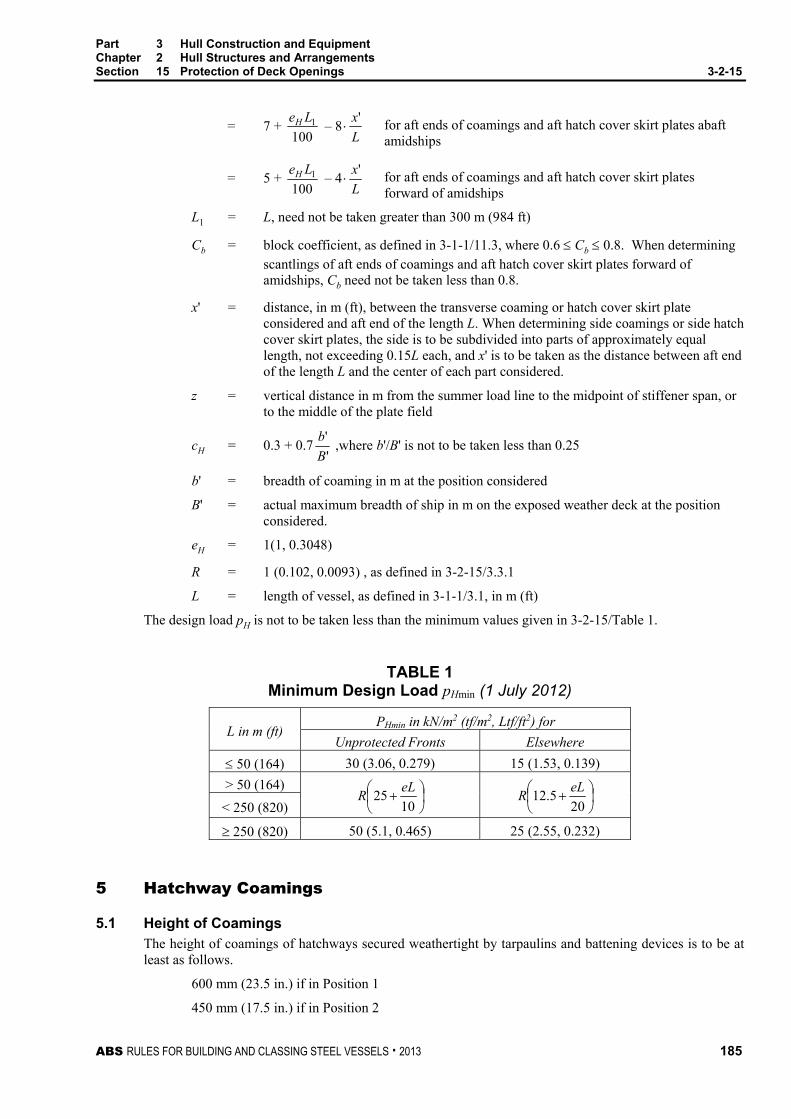
Part 3 Hull Construction and Equipment Chapter 2 Hull Structures and Arrangements Section 15 Protection of Deck Openings 3-2-15
ABS RULES FOR BUILDING AND CLASSING STEEL VESSELS . 2013 185
= 7 + 100
1LeH – 8L
x' for aft ends of coamings and aft hatch cover skirt plates abaft
amidships
= 5 + 100
1LeH – 4L
x' for aft ends of coamings and aft hatch cover skirt plates
forward of amidships
L1 = L, need not be taken greater than 300 m (984 ft)
Cb = block coefficient, as defined in 3-1-1/11.3, where 0.6 Cb 0.8. When determining scantlings of aft ends of coamings and aft hatch cover skirt plates forward of amidships, Cb need not be taken less than 0.8.
x' = distance, in m (ft), between the transverse coaming or hatch cover skirt plate considered and aft end of the length L. When determining side coamings or side hatch cover skirt plates, the side is to be subdivided into parts of approximately equal length, not exceeding 0.15L each, and x' is to be taken as the distance between aft end of the length L and the center of each part considered.
z = vertical distance in m from the summer load line to the midpoint of stiffener span, or to the middle of the plate field
cH = 0.3 + 0.7'
'
B
b ,where b'/B' is not to be taken less than 0.25
b' = breadth of coaming in m at the position considered
B' = actual maximum breadth of ship in m on the exposed weather deck at the position considered.
eH = 1(1, 0.3048)
R = 1 (0.102, 0.0093) , as defined in 3-2-15/3.3.1
L = length of vessel, as defined in 3-1-1/3.1, in m (ft)
The design load pH is not to be taken less than the minimum values given in 3-2-15/Table 1.
TABLE 1 Minimum Design Load pHmin (1 July 2012)
L in m (ft) PHmin in kN/m2 (tf/m2, Ltf/ft2) for
Unprotected Fronts Elsewhere
50 (164) 30 (3.06, 0.279) 15 (1.53, 0.139)
> 50 (164)
1025
eLR
205.12
eLR
< 250 (820)
250 (820) 50 (5.1, 0.465) 25 (2.55, 0.232)
5 Hatchway Coamings
5.1 Height of Coamings The height of coamings of hatchways secured weathertight by tarpaulins and battening devices is to be at least as follows.
600 mm (23.5 in.) if in Position 1
450 mm (17.5 in.) if in Position 2
Part 3 Hull Construction and Equipment Chapter 2 Hull Structures and Arrangements Section 15 Protection of Deck Openings 3-2-15
186 ABS RULES FOR BUILDING AND CLASSING STEEL VESSELS . 2013
Where hatch covers are made of steel or other equivalent material and made tight by means of gaskets and clamping devices, these heights may be reduced, or the coamings omitted entirely, provided that the safety of the vessel is not thereby impaired in any sea condition.
5.3 Coaming Plates Coaming plates are not to be less than 11 mm (0.44 in.) thick.
5.5 Coaming Stiffening Horizontal stiffeners are to be fitted on coamings in Position 1; they are to be not more than 254 mm (10 in.) below the upper edge of the coaming. The breadth of the stiffeners is not to be less than 175 mm (7 in.). Effective brackets or stays are to be fitted from the stiffeners to the deck at intervals of not more than 3 m (10 ft). All exposed coamings other than Position 1 which are 760 mm (30 in.) or more in height are to be similarly supported. Where the height of any exposed coaming exceeds 915 mm (36 in.), the arrangement of the stiffeners and brackets or stays is to be such as to provide equivalent support. Where end coamings are protected, the arrangement of the stiffeners and brackets or stays may be modified.
Where chocks are provided on the coaming to limit the horizontal movement of the hatch cover, the strength of the coaming and deck structure is to be adequate to withstand the load on these chocks. Similar consideration is to be given to pads supporting the weight from hatch covers.
5.7 Protection of Coaming Edges Heavy convex moldings are to be fitted at the upper edges of all exposed coamings of hatches sealed by tarpaulins and battens, as protection against chafing as well as damage to the coaming. The lower edge of the coaming is to be flanged or provided with other suitable protection against damage unless the spaces served by the hatchway are intended exclusively for specialized cargoes such as containers.
5.9 Continuous Longitudinal Hatch Coamings Where strength deck longitudinal hatch coamings of length greater than 0.14L are effectively supported by longitudinal bulkheads or deep girders, as indicated in 3-2-1/13, they are in general to be longitudinally stiffened. The coaming thickness is to be not less than required by 3-2-3/Table 2, equation 2b, and the longitudinal stiffeners not less than required by 3-2-7/3.1 for strength deck longitudinal beams; where s is the spacing of the stiffeners, is the distance between coaming brackets and h is as given in column b of 3-2-7/Table 1. Special consideration will be given to the coaming scantlings where adequate buckling strength is shown to be otherwise provided.
7 Hatchways Closed by Portable Covers and Secured Weathertight by Tarpaulins and Battening Devices (1997)
7.1 Pontoon Covers
7.1.1 Scantlings (1 January 2005)
Where steel pontoon covers are used in place of portable beams and covers, the maximum allowable stress and deflection under the design pressures in 3-2-15/3.3, and the minimum required top plate thickness are as follows.
Maximum allowable stress 0.68Y
Maximum allowable deflection 0.0044 times the span
Top plate thickness 0.01s, but not less than 6 mm (0.24 in.)
where
Y = specified minimum upper yield point strength of the materials, in N/mm2 (kgf/mm2, psi)
s = stiffener spacing
Covers are to be assumed to be simply supported.

Part 3 Hull Construction and Equipment Chapter 2 Hull Structures and Arrangements Section 15 Protection of Deck Openings 3-2-15
ABS RULES FOR BUILDING AND CLASSING STEEL VESSELS . 2013 187
Where the cross section of hatch cover stiffeners is not constant along the span, Appendix 3-2-A6 may be used to determine required scantlings.
7.1.2 Cleats Cleats are to be set to fit the taper of the wedges. They are to be at least 65 mm (2.5 in.) wide and spaced not more than 600 mm (23.5 in.) center to center. The cleats along each side or end are to be not more than 150 mm (6 in.) from the hatch corners.
7.1.3 Wedges Wedges are to be of tough wood; they are to have a taper of not more than 1 in 6 and are to be not less than 13.0 mm (0.50 in.) thick at the toes.
7.1.4 Battening Bars Battening bars are to be provided for properly securing the tarpaulins; they are to have a width of 64 mm (2.5 in.) and a thickness of not less than 9.5 mm (0.375 in.).
7.1.5 Tarpaulins At least two tarpaulins thoroughly waterproofed and of ample strength are to be provided for each exposed hatchway. The material is to be guaranteed free from jute and is to be of an approved type. Synthetic fabrics which have been demonstrated to be equivalent will be specially approved
7.1.6 Security of Hatch Covers For all hatchways in Position 1 or 2, steel bars or other equivalent means are to be provided in order to efficiently and independently secure each section of hatch covers after the tarpaulins are battened down. Hatch covers of more than 1.5 m (4.9 ft) in length are to be secured by at least two such securing appliances.
7.3 Wood Hatch Covers 7.3.1 Hatch Boards
Wood hatch covers on exposed hatchways are to have a finished thickness not less than 60 mm (2.375 in.), where the span is not more than 1.5 m (4.9 ft). The wood is to be of satisfactory quality, straight-grained, reasonably free from knots, sap and shakes, and is to be examined before being coated. Hatch rests are to be beveled where necessary, so as to provide a solid bearing surface.
7.3.2 Portable Beams (1 January 2005) Where portable beams for supporting wood hatch boards are made of steel, the maximum allowable stress and deflection under the design loads in 3-2-15/3.3 are as follows.
Maximum allowable stress 0.68Y
Maximum allowable deflection 0.0044 times the span
where Y is as defined in 3-2-15/7.1.1.
Where the cross section of portable beams is not constant along the span, Appendix 3-2-A6 may be used to determine required beam scantlings.
7.3.3 Closing/Securing Arrangements Closing arrangements are to be in accordance with 3-2-15/7.1.2 through 3-2-15/7.1.6.
7.3.4 Carriers and Sockets Carriers or sockets for portable beams are to be of substantial construction, and are to provide means for the efficient fitting and securing of the beams. Where rolling types of beams are used, the arrangements are to ensure that the beams remain properly in position when the hatchway is closed. The bearing surface is not to be less than 75 mm (3 in.) in width measured along the axis of the beam unless the carriers are of an interlocking type with the beam ends. Carriers for beams are to extend to the deck level or the coamings are to be fitted with stiffeners or external brackets in way of each beam.
Part 3 Hull Construction and Equipment Chapter 2 Hull Structures and Arrangements Section 15 Protection of Deck Openings 3-2-15
188 ABS RULES FOR BUILDING AND CLASSING STEEL VESSELS . 2013
7.5 Steel Hatch Covers 7.5.1 Scantlings (1 January 2005)
Where steel hatch covers are fitted on portable beams in place of wooden hatch boards, the maximum allowable stress and deflection under the design loads in 3-2-15/3.3 are as follows.
Maximum allowable stress 0.8Y, and not exceed the critical buckling strength in compression
Maximum allowable deflection 0.0056 times the span
Top plate thickness 0.01s, but not less than 6 mm (0.24 in.)
where Y is as defined in 3-2-15/7.1.1.
Covers are to be assumed to be simply supported.
Portable beams are to be in accordance with 3-2-15/7.3.2.
7.5.2 Closing Arrangements Closing arrangements are to be in accordance with 3-2-15/7.1.2 through 3-2-15/7.1.6.
7.7 Bearing Surface The width of each bearing surface for hatchway covers is to be at least 65 mm (2.5 in.).
7.9 Materials Other Than Steel The strength and stiffness of covers made of materials other than steel are to be equivalent to those of steel and will be subject to special consideration.
9 Hatchways Closed by Covers of Steel Fitted with Gaskets and Clamping Devices (1 July 2012) These requirements apply to all ships except bulk carriers, ore carriers and combination carriers and are for all cargo hatch covers and coamings on exposed decks. Bulk carriers, ore carriers and combination carriers are to comply with the requirements of 5C-3-4/19.
9.1 Strength of Covers 9.1.1 Stresses
The equivalent stress σe in steel hatch cover structures related to the net thickness shall not exceed 0.8Y, where Y is specified minimum upper yield point strength of the material in N/mm2 (kgf/mm2, psi). For design loads according to 3-2-15/3.5 and 3-2-15/9.9 to 3-2-15/9.13, the equivalent stress σe related to the net thickness shall not exceed 0.9Y when the stresses are assessed by means of FEM using plane stress or shell element
For beam element calculations and grillage analysis, the equivalent stress may be taken as follows:
σe = 22 3τσ + N/mm2 (kgf/mm2, psi)
where
σ = normal stress, in N/mm2 (kgf/mm2, psi)
τ = shear stress, in N/mm2 (kgf/mm2, psi)
For FEM calculations, the equivalent stress may be taken as follows:
σe = 222 3τσσσσ ++⋅− yyxx N/mm2 (kgf/mm2, psi)
Part 3 Hull Construction and Equipment Chapter 2 Hull Structures and Arrangements Section 15 Protection of Deck Openings 3-2-15
ABS RULES FOR BUILDING AND CLASSING STEEL VESSELS . 2013 189
where
σx = normal stress in x-direction, in N/mm2 (kgf/mm2, psi)
σy = normal stress in y-direction, in N/mm2 (kgf/mm2, psi)
τ = shear stress in the x-y plane, in N/mm2 (kgf/mm2, psi)
Indices x and y are coordinates of a two-dimensional Cartesian system in the plane of the considered structural element.
In case of FEM calculations using shell or plane strain elements, the stresses are to be read from the center of the individual element. Where shell elements are used, the stresses are to be evaluated at the mid plane of the element.
The value for cargo hatch covers for bulk carriers, ore carriers and combination carriers is given in 5C-3-4/19.3.1(a).
9.1.2 Deflection The maximum vertical deflection of primary supporting members due to the vertical design load according to 3-2-15/3.3 is:
δvmax = 0.0056g
where
g = greatest span of primary supporting members
Where hatch covers are arranged for carrying containers and mixed stowage is allowed (i.e., a 40-foot container stowed on top of two 20-foot containers, particular attention should be paid to the deflections of hatch covers. Further the possible contact of deflected hatch covers with in hold cargo has to be observed.
9.1.3 Material Hatch covers and coamings are to be made of material in accordance with 3-1-2/Table 1 applying Class I requirements.
The strength and stiffness of covers made of materials other than steel is to be equivalent to those of steel and is to be subject to special consideration.
9.1.4 General Requirements Primary supporting members and secondary stiffeners of hatch covers are to be continuous over the breadth and length of hatch covers, as far as practical. When this is impractical, sniped end connections are not to be used and appropriate arrangements are to be adopted to ensure sufficient load carrying capacity.
The spacing of primary supporting members parallel to the direction of secondary stiffeners is not to exceed 1/3 of the span of primary supporting members. When strength calculation is carried out by FE analysis using plane strain or shell elements, this requirement can be waived.
Secondary stiffeners of hatch coamings are to be continuous over the breadth and length of hatch coamings.
9.1.5 Net Scantling Approach Unless otherwise quoted, the thicknesses t of the following sections are net thicknesses.
The net thicknesses are the member thicknesses necessary to obtain the minimum net scantlings required by 3-2-15/9.1 through 3-2-15/9.17 and 3-2.15/9.21.
The required gross thicknesses are obtained by adding corrosion additions, tS, given in 3-2-15/Table 8.
Strength calculations using beam theory, grillage analysis or FEM are to be performed with net scantlings.

Part 3 Hull Construction and Equipment Chapter 2 Hull Structures and Arrangements Section 15 Protection of Deck Openings 3-2-15
190 ABS RULES FOR BUILDING AND CLASSING STEEL VESSELS . 2013
9.3 Local Net Plate Thickness The minimum local net plate thickness t of the hatch cover top plating is:
t = 15.8Fps Yp95.0
mm
t = 23.64Fps Yp95.0
in.
but not less than 1% of the spacing of the stiffener or 6 mm (0.24 in.) if that be greater.
where
Fp = factor for combined membrane and bending response
= 1.5 in general
= 2.375Yσ for
Y8.0σ ≥ 0.8 for the attached plate flange of primary supporting members
s = stiffener spacing, in m (ft)
p = pressure pV and pL, as defined in 3-2-15/3.5 and 3-2-15/9.9.1, in kN/m2 (tf/m2, Ltf/ft2)
σ = normal stress of hatch cover top plating, in N/mm2 (kgf/mm2, psi)
Y is as defined in 3-2-15/9.1
For flange plates under compression sufficient buckling strength according to 3-2-15/9.17 is to be demonstrated.
The normal stress σ of the hatch cover plating may be determined in a distance s from webs of adjacent primary supporting members perpendicular to secondary stiffeners and in a distance s/2 from the web of an adjacent primary supporting member parallel to secondary stiffeners, refer to 3-2-15/Figure 3. The greater of both stresses is to be taken. For the distribution of normal stress σ between two parallel girders, refer to 3-2-15/9.17.3(b).
FIGURE 3 Determination of Normal Stress of the Hatch Cover Plating (1 July 2012)
s
y
x
s
21
s/2σx1σy2
σ = max[σx1 (y = s/2); σy2 (x = s)]

Part 3 Hull Construction and Equipment Chapter 2 Hull Structures and Arrangements Section 15 Protection of Deck Openings 3-2-15
ABS RULES FOR BUILDING AND CLASSING STEEL VESSELS . 2013 191
9.3.1 Local Gross Plate Thickness of Hatch Covers for Wheel Loading The local gross plate thickness of hatch covers subject to wheel loading is to be as given in, refer to 3-2-3/5.7.
Where the hatch cover is subject to other load as well, the hatch cover is to coupling with the applicable requirement in 3-2-15/9.
9.3.2 Lower Plating of Double Skin Hatch Covers and Box Girders The thickness to fulfill the strength requirements is to be obtained from the calculation according to 3-2-15/9.15 under consideration of permissible stresses according to 3-2-15/9.1.1.
The net thickness must not be less than the value when the lower plating is taken into account as a strength member of the hatch cover
t = 6.5s mm
= 0.078s in.
but not less than 5 mm (0.20 in.)
where s is as defined in 3-2-15/9.3
When the lower plating is not considered as a strength member of the hatch cover, the thickness of the lower plating will be specially considered.
9.5 Net Scantlings of Secondary Stiffeners The net section modulus Z and net shear area As of uniformly loaded hatch cover stiffeners constrained at both ends must not be less than:
Z = Y
104 ss2s p cm3
= Y
2793 ss2s p in3
As = Y
ps ss10 cm2
= Y
ps ss882 in2
where
s = secondary stiffener span, to be taken as the spacing of primary supporting members or the distance between a primary supporting member and the edge support, in m (ft)
ss = secondary stiffener spacing in m (ft)
Y is as defined in 3-2-15/9.1
p is as defined in 3-2-15/9.3
The net section modulus of the secondary stiffeners is to be determined based on an attached plate width assumed equal to the stiffener spacing.
For flat bar secondary stiffeners and buckling stiffeners, the ratio h/tw is to be not greater than following equation:
wth ≤ 15k0.5

Part 3 Hull Construction and Equipment Chapter 2 Hull Structures and Arrangements Section 15 Protection of Deck Openings 3-2-15
192 ABS RULES FOR BUILDING AND CLASSING STEEL VESSELS . 2013
where
h = height of the stiffener, in m (ft)
tw = net thickness of the stiffener, in m (ft)
k = 235/Y (23.963/Y, 34084/Y)
Y is as defined in 3-2-15/9.1
Stiffeners parallel to primary supporting members and arranged within the effective breadth according to 3-2-15/9.15.1 must be continuous at crossing primary supporting member and may be regarded for calculating the cross sectional properties of primary supporting members. It is to be verified that the combined stress of those stiffeners induced by the bending of primary supporting members and lateral pressures does not exceed the permissible stresses according to 3-2-15/9.1.1.
For hatch cover stiffeners under compression sufficient safety against lateral and torsional buckling according to 3-2-15/9.17.3 is to be verified.
For hatch covers subject to wheel loading stiffener scantlings are to be determined by direct calculations under consideration of the permissible stresses according to 3-2-15/9.1.1.
9.7 Net Scantlings of Primary Supporting Members 9.7.1 Primary Supporting Members
Scantlings of primary supporting members are obtained from calculations according to 3-2-15/9.15 under consideration of permissible stresses according to 3-2-15/9.1.1.
For all components of primary supporting members sufficient safety against buckling must be verified according to 3-2-15/9.17. For biaxial compressed flange plates this is to be verified within the effective widths according to 3-2-15/9.17.3(b).
The net thickness of webs of primary supporting members shall not be less than:
t = 6.5s mm
= 0.078s in.
but not less than 5 mm (0.20 in.)
where s is as defined in 3-2-15/9.3
9.7.2 Edge Girders (Skirt Plates) Scantlings of edge girders are obtained from the calculations according to 3-2-15/9.15 under consideration of permissible stresses according to 3-2-15/9.1.1.
The net thickness of the outer edge girders exposed to wash of sea shall not be less than the largest of the following values:
t = 15.8sY
pH
95.0 mm
= 8.5s mm
t = 23.652sY
pH
95.0 in.
= 0.102s in.
but not less than 5 mm (0.20 in.)
where
pH is as defined in 3-2-15/3.5.
Y is as defined in 3-2-15/9.1.
s is as defined in 3-2-15/9.3.

Part 3 Hull Construction and Equipment Chapter 2 Hull Structures and Arrangements Section 15 Protection of Deck Openings 3-2-15
ABS RULES FOR BUILDING AND CLASSING STEEL VESSELS . 2013 193
The stiffness of edge girders is to be sufficient to maintain adequate sealing pressure between securing devices. The moment of inertia of edge girders is not to be less than:
I = uq 4SDs cm4 (in4)
where
u = 6 (58.842, 7.693·10-3)
q = packing line pressure, in N/mm (kgf/mm, lbf/in). Minimum 5 N/mm (0.51 kgf/mm, 28.55 lbf/in)
sSD = spacing of securing devices, in m (ft)
9.9 Cargo Loads 9.9.1 Distributed Loads
The load on hatch covers due to cargo loads pL resulting from heave and pitch is to be determined according to the following formula:
pL = pC(1 + aa) kN/m2 (tf/m2, Ltf/ft2)
where
pC = uniform cargo load, in kN/m2 (tf/m2, Ltf/ft2)
aa = acceleration addition
= FDmD
FD = 0.11Le
v
H
0
mD = m0 – 5(m0 – 1) Lx′
for 0 ≤ Lx′
≤ 0.2
= 1.0 for 0.2 < Lx′
≤ 0.7
=
−
′++ 7.0
3.01
1 0
Lxm
for 0.7 < Lx′
≤ 1.0
m0 = 1.5 + F
v0 = maximum speed at summer load line draft, in knots. v0 is not to be taken less than LeH
eH = 1 (1,0.3048)
x' = distance between the transverse coaming or hatch cover skirt plate considered and aft end of the length L, in m (ft)
L is as defined in 3-1-1/3.1.
9.9.2 Point Loads The loads due to single forces PP resulting from heave and pitch (e.g., in case of containers) are to be determined as follows:
PP = PS(1 + aa) kN (tf, Ltf)
where
PS = single force, in kN (tf, Ltf)
aa is as defined in 3-2-15/9.9.1.

Part 3 Hull Construction and Equipment Chapter 2 Hull Structures and Arrangements Section 15 Protection of Deck Openings 3-2-15
194 ABS RULES FOR BUILDING AND CLASSING STEEL VESSELS . 2013
9.11 Container Loads Where containers are stowed on hatch covers, the following loads due to heave, pitch, and the vessel’s rolling motion are to be considered, see also 3-2-15/Figure 4:
Az = ( )
−⋅+⋅
P
ma f
haM 42.045.01
2 kN (tf, Ltf)
Bz = ( )
+⋅+⋅
P
ma f
haM 42.045.01
2 kN (tf, Ltf)
By = 0.24465M kN (tf, Ltf)
where
Az, Bz = support forces in z-direction at the forward and aft stack corners
By = support force in y-direction at the forward and aft stack corners
M = maximum designed mass of container stack, in kN (tf, Ltf)
hm = designed height of center of gravity of stack above hatch cover supports, in m (ft)
fP = distance between foot points, in m (ft)
aa is as defined in 3-2-15/9.9.1.
For M and hm it is recommended to apply those values, which are used for the calculations of cargo securing (container lashing). If different assumptions are made for M and hm, the designer has to ensure that, in the calculation model, the hatch cover structure is not loaded less than by those values recommended.
When strength of the hatch cover structure is assessed by FE analysis according to 3-2-15/9.15.2 using shell or plane strain elements, hm may be taken as the designed height of center of gravity of stack above the hatch cover top plate.
Values of M and hm applied for the assessment of hatch cover strength are to be shown in the drawings of the hatch covers.
FIGURE 4 Forces due to Container Loads (1 July 2012)
hm
fP
Az
Bz
By
M
In case of container stacks secured to lashing bridges or carried in cell guides the forces acting on the hatch cover may be specially considered.
Alternatively, container loads may be applied based on accelerations calculated by an individual acceleration analysis for the used lashing (See 6/3.7 of the ABS Guide for Certification of Container Securing Systems)

Part 3 Hull Construction and Equipment Chapter 2 Hull Structures and Arrangements Section 15 Protection of Deck Openings 3-2-15
ABS RULES FOR BUILDING AND CLASSING STEEL VESSELS . 2013 195
9.11.1 Load Cases with Partial Loading The load cases 3-2-15/9.9 and 3-2-15/9.11 are also to be considered for partial non homogeneous loading which may occur in practice (e.g., where specified container stack places are empty). The load case “partial loading of container hatch covers” can be evaluated using a simplified approach, where the hatch cover is loaded without the outermost stacks, see 3-2-15/Figure 5.
FIGURE 5 Partial Loading of a Container Hatch Cover (1 July 2012)
9.13 Loads due to Elastic Deformations of the Vessel’s Hull Hatch covers, which in addition to the loads according to 3-2-15/3.3 to 3-2-15/3.5 and 3-2-15/9.9 to 3-2-15/9.11 are loaded in the vessel’s transverse direction by forces due to elastic deformations of the vessel’s hull, are to be designed such that the sum of stresses does not exceed the permissible values given in 3-2-15/9.1.1.
9.15 Strength Calculations Strength calculation for hatch covers may be carried out by either, using beam theory, grillage analysis or FEM.
9.15.1 Effective Cross-sectional Properties for Calculation by Beam Theory or Grillage Analysis Cross-sectional properties are to be determined considering the effective breadth. Cross sectional areas of secondary stiffeners parallel to the primary supporting member under consideration within the effective breadth can be included, see 3-2-15/Figure 7.
The effective breadth of plating em of primary supporting members is to be determined according to 3-2-15/Table 2, considering the type of loading. Special calculations may be required for determining the effective breadth of one-sided or non-symmetrical flanges.
The effective cross sectional area of plates is not to be less than the cross sectional area of the face plate.
For flange plates under compression with secondary stiffeners perpendicular to the web of the primary supporting member, the effective width is to be determined according to 3-2-15/9.17.3(b).

Part 3 Hull Construction and Equipment Chapter 2 Hull Structures and Arrangements Section 15 Protection of Deck Openings 3-2-15
196 ABS RULES FOR BUILDING AND CLASSING STEEL VESSELS . 2013
TABLE 2 Effective Breadth em of Plating of Primary Supporting Members (1 July 2012)
/e 0 1 2 3 4 5 6 7 ≥ 8 em1/e 0 0.36 0.64 0.82 0.91 0.96 0.98 1.00 1.00 em2/e 0 0.20 0.37 0.52 0.65 0.75 0.84 0.89 0.90
em1 is to be applied where primary supporting members are loaded by uniformly distributed loads or else by not less than 6 equally spaced single loads
em2 is to be applied where primary supporting members are loaded by 3 or less single loads
Intermediate values may be obtained by direct interpolation.
length of zero-points of bending moment curve:
= 0 for simply supported primary supporting members
= 0.6 0 for primary supporting members with both ends constraint,
where 0 is the unsupported length of the primary supporting member
e width of plating supported, measured from center to center of the adjacent unsupported fields
9.15.2 General Requirements for FEM Calculations For strength calculations of hatch covers by means of finite elements, the cover geometry shall be idealized as realistically as possible. Element size must be appropriate to account for effective breadth. In no case element width shall be larger than stiffener spacing. In way of force transfer points and cutouts the mesh has to be refined where applicable. The ratio of element length to width shall not exceed 4.
The element height of webs of primary supporting member must not exceed one-third of the web height. Stiffeners, supporting plates against pressure loads, have to be included in the idealization. Buckling stiffeners may be disregarded for the stress calculation.
9.17 Buckling Strength of Hatch Cover Structures For hatch cover structures sufficient buckling strength is to be demonstrated.
Definitions
a = length of the longer side of a single plate field (x-direction), in mm (in.)
b = breadth of the shorter side of a single plate field (y-direction), in mm (in.)
αr = aspect ratio of single plate field
= a/b
n = number of single plate field breadths within the partial or total plate field
t = net plate thickness in mm (in.)
σmx = membrane stress in x-direction, in N/mm2 (kgf/mm2, psi)
σmy = membrane stress in y-direction, in N/mm2 (kgf/mm2, psi)
τ = shear stress in the x-y plane, in N/mm2 (kgf/mm2, psi)
Compressive and shear stresses are to be taken positive; tension stresses are to be taken negative.

Part 3 Hull Construction and Equipment Chapter 2 Hull Structures and Arrangements Section 15 Protection of Deck Openings 3-2-15
ABS RULES FOR BUILDING AND CLASSING STEEL VESSELS . 2013 197
FIGURE 6 General Arrangement of Panel (1 July 2012)
b
a
xy
nbbmam
single field partial fieldlong. stiffener
transverse stiffener
longitudinal: stiffener in the direction of the length atransverse: stiffener in the direction of the breadth b
If stresses in the x- and y-direction already contain the Poisson-effect (calculated using FEM), the following modified stress values may be used. Both stresses *
xσ and *yσ are to be compressive stresses, in order to
apply the stress reduction according to the following formulae:
σmx = ( *xσ – 0.3 *
yσ )/0.91
σmy = ( *yσ – 0.3 *
xσ )/0.91
where *xσ , *
yσ = stresses containing the Poisson-effect
Where compressive stress fulfills the condition *yσ < 0.3 *
xσ , then σmy = 0 and σmx = *xσ
Where compressive stress fulfills the condition *xσ < 0.3 *
yσ , then σmx = 0 and σmy = *yσ
The correction factor (F1) for boundary condition at the longitudinal stiffeners is defined in 3-2-15/Table 3.
TABLE 3 Correction Factor F1 (1 July 2012)
Stiffeners sniped at both ends 1.00
Guidance values(1) where both ends are effectively connected to adjacent structures
1.05 1.10 1.20 1.30
for flat bars for bulb sections for angle and tee-sections for u-type sections(2) and girders of high rigidity
An average value of F1 is to be used for plate panels having different edge stiffeners.
Notes: 1 Exact values may be determined by direct calculations.
2 Higher value may be taken if it is verified by a buckling strength check of the partial plate field using non-linear FEA but not greater than 2.0.

Part 3 Hull Construction and Equipment Chapter 2 Hull Structures and Arrangements Section 15 Protection of Deck Openings 3-2-15
198 ABS RULES FOR BUILDING AND CLASSING STEEL VESSELS . 2013
σr = reference stress
= 0.9E2
bt , in N/mm2 (kgf/mm2, psi)
ψ = edge stress ratio taken equal to:
= σ2/σ1
σ1 = maximum compressive stress, in N/mm2 (kgf/mm2, psi)
σ2 = minimum compressive stress or tension stress, in N/mm2 (kgf/mm2, psi)
SF = safety factor (based on net scantling approach), taken equal to:
= 1.25 for hatch covers when subjected to the vertical design load according to 3-2-15/3.3
= 1.10 for hatch covers when subjected to loads according to 3-2-15/3.5 and 3-2-15/9.9 to 3-2-15/9.13
λ = reference degree of slenderness, taken equal to:
= rK
Yσ
K = buckling factor according to 3-2-15/Table 5
Y is as defined in 3-2-15/9.1.1.
E is as defined in 3-2-A4/3.1.1.
9.17.1 Strength of Hatch Cover Plating Each single plate field of the top and bottom plating of the hatch cover are to satisfy the following condition:
3
2
221 3e
mymx
e
y
mye
x
mx
YSF
YSF
BY
SF
YSF
+
−
+
τκτσσ
κ
σ
κσ
≤ 1.0
The first two terms and the last term of the above condition shall not exceed 1.0.
The reduction factors κx, κy and κτ are given in 3-2-15/Table 4.
Where σmx ≤ 0 (tension stress), κx = 1.0.
Where σmy ≤ 0 (tension stress), κy = 1.0.
The exponents e1, e2, and e3 as well as the factor B are to be taken as given in 3-2-15/Table 4.

Part 3 Hull Construction and Equipment Chapter 2 Hull Structures and Arrangements Section 15 Protection of Deck Openings 3-2-15
ABS RULES FOR BUILDING AND CLASSING STEEL VESSELS . 2013 199
TABLE 4 Coefficients e1, e2, e3 and Factor B (1 July 2012)
Exponents e1 - e3 and Factor B
Plate Panel
e1 1 + 4xκ
e2 1 + 4yκ
e3 1 +κx κy 2τκ
B σmx and σmy positive (compression stress)
( )5yxκκ
B σmx or σmy negative
(tension stress) 1

Part 3 Hull Construction and Equipment Chapter 2 Hull Structures and Arrangements Section 15 Protection of Deck Openings 3-2-15
200 ABS RULES FOR BUILDING AND CLASSING STEEL VESSELS . 2013
TABLE 5 Buckling and Reduction Factors for Plane Elementary Plate Panels (1 July 2012)
Buckling Load Case
Edge Stress Ratio ψ
Aspect Ratio
αr = a/b Buckling Factor K Reduction Factor κ
1 σmx σmx
αr · bψ · σmx ψ · σmx
t b
1 ≥ ψ ≥ 0
αr ≥ 1
K = 1.1
4.8+ψ
κx = 1 for λ ≤ λc
κx = c
λ−
λ 222.01 for λ > λc
c = (1.25 – 0.12ψ) ≤ 1.25
λc =
−+
cc 88.0112
0 ≥ ψ ≥ –1 K = 7.63 – ψ(6.26 – 10ψ)
ψ ≤ –1 K = 5.975(1 – ψ)2
2
αr · b
ψ · σmy
t b
ψ · σmy
σmy
1 ≥ ψ ≥ 0 αr ≥ 1 K = F1 ( )1.11.211
2
2 +⋅
+
ψα r
κy = c ( )
λ−+
−λ 2
21 RHFR
c = (1.25 – 0.12ψ) ≤ 1.25
R = λ
λ
−c
1 for λ < λc
R = 0.22 for λ ≥ λc
λc =
−+
cc 88.0112
F = 01
91.01 12 ≥⋅
λ
−− c
K
p
2pλ = λ2 – 0.5 for 1 ≤ 2
pλ ≤ 3
c1 =
−
r
Fα
11 ≥ 0
H = λ –
−+
λ
4
22TTc
≥ R
T = λ + 31
1514
+λ
0 ≥ ψ ≥ –1
1 ≤ αr ≤ 1.5
K = F1( )
+⋅
+
1.111.211
2
2ψ
α r
( )
−− ψ
αψ 109.132
r
αr > 1.5
K = F1( )
+⋅
+
1.111.211
2
2ψ
α r
( 22 87.187.5 rr
ααψ
−−
)
−+ ψ
α106.8
2r
ψ ≤ –1
1 ≤ αr ≤ ( )
413 ψ− K = 5.975F1
21
−
rαψ
αr > ( )
413 ψ−
K = F1
−2
19675.3rαψ
+
−+ 87.115375.0
4
rαψ
Explanations for boundary conditions - - - - - plate edge free ──── plate edge simply supported

Part 3 Hull Construction and Equipment Chapter 2 Hull Structures and Arrangements Section 15 Protection of Deck Openings 3-2-15
ABS RULES FOR BUILDING AND CLASSING STEEL VESSELS . 2013 201
TABLE 5 (continued) Buckling and Reduction Factors for Plane Elementary Plate Panels (1 July 2012)
Buckling Load Case
Edge Stress Ratio ψ
Aspect Ratio
αr = a/b Buckling Factor K Reduction Factor κ
3 σmx σmx
αr · bψ · σmx ψ · σmx
t b
1 ≥ ψ ≥ 0
αr > 0 K =
13
1425.04 2
+
+
ψα r
κx = 1 for λ ≤ 0.7
κx = 51.0
12 +λ
for λ > 0.7 0 ≥ ψ ≥ –1
K = 4
+
21425.0rα
(1 + ψ)
– 5ψ (1 – 3.42ψ) 4
αr · bσmx σmx
ψ · σmx ψ · σmx
t b
1 ≥ ψ ≥ –1 αr > 0 K =
+
21425.0rα 2
3 ψ−
5
αr · b
t bτ τ
τ
τ
-----
----- K = Kτ · 3
κτ = 1 for λ ≤ 0.84
κτ = λ84.0 for λ > 0.84
αr ≥ 1 Kτ =
+ 2
434.5rα
0 < αr < 1 Kτ =
+ 2
34.54rα
Explanations for boundary conditions - - - - - plate edge free ──── plate edge simply supported
9.17.2 Webs and Flanges of Primary Supporting Members For non-stiffened webs and flanges of primary supporting members sufficient buckling strength as for the hatch cover top and bottom plating is to be demonstrated according to 3-2-15/9.17.1.
9.17.3 Strength of Partial and Total Fields of Hatch Covers 9.17.3(a) Longitudinal and Transverse Secondary Stiffeners. It is to be demonstrated that the continuous longitudinal and transverse stiffeners of partial and total plate fields comply with the conditions set out in 3-2-15/9.17.3(c) through 3-2-15/9.17.3(d).
9.17.3(b) Effective Width of Hatch Cover Top and Bottom Plating. For demonstration of buckling strength according to 3-2-15/19.17.3(c) through 3-2-15/19.17.3(d) the effective width of plating may be determined by the following formulae:
bm = κx · b for longitudinal stiffeners, in mm (in.)
am = κy · a for transverse stiffeners, in mm (in.)
where
a and b are as defined in 3-2-15/9.17.
κx, κy are as defined in 3-2-15/9.17.1.
See also 3-2-15/Figure 6.
The effective width of plating is not to be taken greater than the value obtained from 3-2-15/9.15.1.

Part 3 Hull Construction and Equipment Chapter 2 Hull Structures and Arrangements Section 15 Protection of Deck Openings 3-2-15
202 ABS RULES FOR BUILDING AND CLASSING STEEL VESSELS . 2013
The effective width me of stiffened flange plates of primary supporting members may be determined as follows:
FIGURE 7 Stiffening Parallel to Web of Primary Supporting Member (1 July 2012)
bm
bbbb
bm
y
em'
em
e
i) Stiffening Parallel to Web of Primary Supporting Member
b < em
me = nbm
n =
b
em
where
bm = effective width of plating for transverse stiffeners, in mm (in.)
e and em are as defined in 3-2-15/9.15.
b and n are as defined in 3-2-15/9.17.

Part 3 Hull Construction and Equipment Chapter 2 Hull Structures and Arrangements Section 15 Protection of Deck Openings 3-2-15
ABS RULES FOR BUILDING AND CLASSING STEEL VESSELS . 2013 203
FIGURE 8 Stiffening Perpendicular to Web of Primary Supporting Member (1 July 2012)
x1
x2x(y)
ii) Stiffening Perpendicular to Web of Primary Supporting Member
a em
me = nam < em
n = 2.7a
em 1
where
am = effective width of plating for longitudinal stiffeners, in mm (in.)
e and em are as defined in 3-2-15/9.15.
a and n are as defined in 3-2-15/9.17.
For b em or a < em, respectively, b and a have to be exchanged. am and bm for flange plates are in general to be determined for = 1.
Scantlings of plates and stiffeners are in general to be determined according to the maximum stresses mx(y) at webs of primary supporting member and stiffeners, respectively. For stiffeners with spacing b under compression arranged parallel to primary supporting members no value less than 0.25Y shall be inserted for mx(y = b).
The stress distribution between two primary supporting members can be obtained by the following formula:
mx(y) = x1
)21(2431 2121 cc
e
ycc
e
y
where
c1 = 1
2
x
x
0 c1 1
c2 = 5.05.1
21 mm eee

Part 3 Hull Construction and Equipment Chapter 2 Hull Structures and Arrangements Section 15 Protection of Deck Openings 3-2-15
204 ABS RULES FOR BUILDING AND CLASSING STEEL VESSELS . 2013
1me ′′ = proportionate effective breadth em1 or proportionate effective width 1me′ of primary supporting member 1 within the distance e, as appropriate, in mm (in.)
2me ′′ = proportionate effective breadth em2 or proportionate effective width 2me′ of primary supporting member 2 within the distance e, as appropriate, in mm (in.)
σx1, σx2 = normal stresses in flange plates of adjacent primary supporting member 1 and 2 with spacing e, based on cross-sectional properties considering the effective breadth or effective width, as appropriate, in N/mm2 (kgf/mm2, psi)
y = distance of considered location from primary supporting member 1, in mm (in.)
e is as defined in 3-2-15/9.15.
Shear stress distribution in the flange plates may be assumed linearly.
9.17.3(c) Lateral Buckling of Secondary Stiffeners.
Yba σσ +
SF ≤ 1
where
σa = uniformly distributed compressive stress in the direction of the stiffener axis
= σmx for longitudinal stiffeners, in N/mm2 (kgf/mm2, psi)
= σmy for transverse stiffeners, in N/mm2 (kgf/mm2, psi)
σb = bending stress in the stiffener
= 310
10⋅+
stZMM
, in N/mm2 (kgf/mm2)
= 998
⋅
+310
10stZMM
, in psi
M0 = bending moment due to the deformation w of stiffener, taken equal to:
= FKizf
z
pcwp
− with (cf – pz) > 0, in N-mm (kgf-mm, lbf-in)
M1 = bending moment due to the lateral load pl equal to:
= 3
2
1024 ⋅bap for longitudinal stiffeners, in N-mm (kgf/mm)
= 3
2
102415593
⋅bap for longitudinal stiffeners, in lbf-in
= 3
2
108)(
⋅scnbap for transverse stiffeners, in N-mm (kgf/mm)
= 3
2
108)(15593
⋅scnbap for transverse stiffeners, in lbf-in
n is as defined in 3-2-15/9.17, to be taken equal to 1 for ordinary transverse stiffeners.
p = lateral load, in kN/m2 (tf/m2, Ltf/ft2)
FKi = ideal buckling force of the stiffener

Part 3 Hull Construction and Equipment Chapter 2 Hull Structures and Arrangements Section 15 Protection of Deck Openings 3-2-15
ABS RULES FOR BUILDING AND CLASSING STEEL VESSELS . 2013 205
FKix = 2
2
aπ EIx · 104 for longitudinal stiffeners, in N (kgf)
= 2
2
aπ EIx for longitudinal stiffeners, in lbf
FKiy = ( )2
2
nbπ EIy · 104 for transverse stiffeners, in N (kgf)
FKiy = ( )2
2
nbπ EIy for transverse stiffeners, in lbf
Ix, Iy = net moments of inertia of the longitudinal or transverse stiffener including effective width of attached plating according to 3-2-15/9.17.3(b). Ix and Iy are to comply with the following criteria:
= Ix ≥ 4
3
1012 ⋅bt cm4
= Ix ≥ 12
3bt in4
= Iy ≥ 4
3
1012 ⋅at cm4
= Iy ≥ 12
3at in4
pz = nominal lateral load of the stiffener due to σx, σy and τ
pzx =
++
1
2
22 τσπσ myyxl cab
bt for longitudinal stiffeners, in N/mm2
(kgf/mm2, psi)
pzy =
+
+
+ 1
2
212 τπσσatA
nbac
at y
myxlx for transverse stiffeners, in
N/mm2 (kgf/mm2, psi)
σxl = σmx
+
btAx1 , in N/mm2 (kgf/mm2, psi)
cx, cy = factor taking into account the stresses perpendicular to the stiffener's axis and distributed variable along the stiffener's length
= 0.5(1 + Ψ) for 0 ≤ Ψ ≤ 1
= Ψ−15.0 for Ψ ≤ 0
Ax, Ay = net sectional area of the longitudinal or transverse stiffener, respectively, without attached plating, in mm2 (in2)
τ1 =
+− 2
221
bm
amYEtτ ≥ 0, in N/mm2 (kgf/mm2, psi)

Part 3 Hull Construction and Equipment Chapter 2 Hull Structures and Arrangements Section 15 Protection of Deck Openings 3-2-15
206 ABS RULES FOR BUILDING AND CLASSING STEEL VESSELS . 2013
for longitudinal stiffeners:
37.096.1:0.2
49.047.1:0.2
21
21
==<
==≥
mmba
mmba
for transverse stiffeners:
221
221
47.149.0:5.0
96.137.0:5.0
nmm
nba
nmm
nba
==<
==≥
w = w0 + w1, in mm (in.)
w0 = assumed imperfection. For stiffeners sniped at both ends, w0 must not be taken less than the distance from the midpoint of plating to the neutral axis of the profile including effective width of plating.
w0x ≤ min
10,
250,
250ba for longitudinal stiffeners, in mm
w0x ≤ min
394.0,
843.9,
843.9ba for longitudinal stiffeners, in inches
w0y ≤ min
10,
250,
250nba for transverse stiffeners, in mm
w0y ≤ min
394.0,
843.9,
843.9nba for transverse stiffeners, in inches
w1 = deformation of stiffener at midpoint of stiffener span due to lateral load p. In case of uniformly distributed load the following values for w1 may be used:
= xEI
bap⋅⋅ 7
4
10384 for longitudinal stiffeners, in mm
= xEI
bap⋅⋅ 2
4
103841550 for longitudinal stiffeners, in inches
= ( )27
4
103845
sycEInbap⋅⋅
for transverse stiffeners, in mm
= ( )2
4
3840775
sycEInbap
⋅ for transverse stiffeners, in inches
cf = elastic support provided by the stiffener

Part 3 Hull Construction and Equipment Chapter 2 Hull Structures and Arrangements Section 15 Protection of Deck Openings 3-2-15
ABS RULES FOR BUILDING AND CLASSING STEEL VESSELS . 2013 207
i) For longitudinal stiffeners:
cfx = FKix 2
2
aπ (1 + cpx), in N/mm2 (kgf/mm2, psi)
cpx =
xa
x
cbt
I
−
⋅
+
1101291.01
1
3
4, in N/mm2 (kgf/mm2)
cpx =
xa
x
cbtI
−
⋅
+11291.0
1
1
3
, in psi
cxa = 22
2
+
ab
ba for a ≥ 2b
= 22
21
+
ba for a < 2b
ii) For transverse stiffeners:
cfy = cSFKiy ( )2
2
nbπ (1 + cpy), in N/mm2 (kgf/mm2, psi)
cpy =
ya
y
cat
I
−
⋅
+
11012
91.0
1
1
3
4, in N/mm2 (kgf/mm2)
cpy =
ya
y
catI
−
+1
1291.0
1
1
3
, in psi
cya = 22
2
+
nba
anb for nb ≥ 2a
=
22
21
+
anb for nb < 2a
cs = factor accounting for the boundary conditions of the transverse stiffener
= 1.0 for simply supported stiffeners
= 2.0 for partially constraint stiffeners
Zst = net section modulus of stiffener (long. or transverse) including effective width of plating according to 3-2-15/9.17.3(b), in cm3 (in3)
Ψ, σmx, σmy, τ, SF, t, a, and b are as defined in 3-2-15/9.17,
Y is as defined in 3-2-15/9.1.1,
Part 3 Hull Construction and Equipment Chapter 2 Hull Structures and Arrangements Section 15 Protection of Deck Openings 3-2-15
208 ABS RULES FOR BUILDING AND CLASSING STEEL VESSELS . 2013
E is as defined in 3-2-A4/3.1.1.
If no lateral load p is acting, the bending stress σb is to be calculated at the midpoint of the stiffener span for the flange which results in the largest stress value. If a lateral load p is acting, the stress calculation is to be carried out for both flanges of the stiffener’s cross sectional area (if necessary for the biaxial stress field at the plating side).
9.17.3(d) Torsional Buckling of Secondary Stiffeners.
i) Longitudinal Secondary Stiffeners. The longitudinal ordinary stiffeners are to comply with the following criteria:
YSF
T
mx
κσ ≤ 1.0
where
κT = coefficient taken equal to:
= 1.0 for λT ≤ 0.2
= 22
1
Tλ−Φ+Φ for λT > 0.2
Φ = 0.5[1 + 0.21(λT – 0.2) + 2Tλ ]
λT = reference degree of slenderness taken equal to:
= KiT
Yσ
σKiT =
+ T
PI
aI
IE 385.010
2
22επ ω , in N/mm2 (kgf/mm2)
=
+ T
PI
aI
IE 385.010
100 2
22επ ω , in psi
For Ip, IT, Iω see 3-2-15/Figure 9 and 3-2-15/Table 6.
Ip = net polar moment of inertia of the stiffener related to the point C, in cm4 (in4)
IT = net St. Venant’s moment of inertia of the stiffener, in cm4 (in4)
Iω = net sectional moment of inertia of the stiffener related to the point C, in cm6 (in6)
ε = degree of fixation taken equal to:
= 1 + 10-3
+ 33
4
4
34
43
w
w
th
tbI
a
ωπ
where Iω in cm6 and b, t, hw, and tw in mm
= 1 +
+ 33
4
4
34
43
w
w
th
tbI
a
ωπ
where Iω in in6 and b, t, hw, and tw in inches

Part 3 Hull Construction and Equipment Chapter 2 Hull Structures and Arrangements Section 15 Protection of Deck Openings 3-2-15
ABS RULES FOR BUILDING AND CLASSING STEEL VESSELS . 2013 209
hw = web height, in mm (in.)
tw = net web thickness, in mm (in.)
bf = flange breadth, in mm (in.)
tf = net flange thickness, in mm (in.)
Aw = net web area
= hwtw, in mm2 (in2)
Af = net flange area
= bftf, in mm2 (in2)
ef = hw + 2ft
, in mm (in.)
SF, σmx, a, and b are as defined in 3-2-15/9.17.
Y is as defined in 3-2-15/9.1.1.
E is as defined in 3-2-A4/3.1.1.
ii) Transverse Secondary Stiffeners. For transverse secondary stiffeners loaded by compressive stresses and which are not supported by longitudinal stiffeners, sufficient torsional buckling strength is to be demonstrated in accordance with 3-2-15/9.17.3(d)i).
FIGURE 9 Dimensions of Stiffeners (1 July 2012)
bf
hw ef
bf bf
tw tw tw tw
C C C C
tf
ta
b1 b1 b2
ef = hw + tf /2

Part 3 Hull Construction and Equipment Chapter 2 Hull Structures and Arrangements Section 15 Protection of Deck Openings 3-2-15
210 ABS RULES FOR BUILDING AND CLASSING STEEL VESSELS . 2013
TABLE 6 Moments of Inertia (1 July 2012)
Section IP IT Iω
Flat bar m
ww
ith
⋅⋅
3
3
−
⋅⋅
w
w
m
ww
ht
ith 63.01
3
3
m
ww
jth
⋅⋅
36
33
Sections with bulb or flange
⋅+
⋅ 22
31
ffww
meAhA
i
−
⋅⋅
w
w
m
ww
ht
ith 63.01
3
3
+
−
⋅
⋅
f
f
m
ff
bt
itb
63.013
3
for bulb and angle sections:
+
+
⋅
⋅⋅
Wf
Wf
m
fff
AAAA
jbeA 6.2
12
22
for tee-sections:
m
fff
jetb
⋅
⋅⋅
12
23
im is 104 for cm4 and 1 for in4
jm is 106 for cm6 and 1 for in6
9.19 Details of Hatch Covers 9.19.1 Container Foundations on Hatch Covers
The substructures of container foundations are to be designed for cargo and container loads according to 3-2-15/3.3 through 3-2-15/3.5 and 3-2-15/9.9 through 3-2-15/9.11 applying the permissible stresses according to 3-2-15/9.1.1.
9.19.2 Weathertightness 9.19.2(a) Packing Material (General). The packing material is to be suitable for all expected service conditions of the ship and is to be compatible with the cargoes to be transported. The packing material is to be selected with regard to dimensions and elasticity in such a way that expected deformations can be carried. Forces are to be carried by the steel structure only.
The packing is to be compressed so as to give the necessary tightness effect for all expected operating conditions. Special consideration shall be given to the packing arrangement in ships with large relative movements between hatch covers and coamings or between hatch cover sections.
9.19.2(b) Dispensation of Weathertight Gaskets. For hatch covers of cargo holds solely for the transport of containers, upon request by the owners and subject to compliance with the following conditions the fitting of weathertight gaskets according to 3-2-15/9.19.2(a) may be dispensed with:
• The hatchway coamings shall be not less than 600 mm (23.622 in.) in height.
• The exposed deck on which the hatch covers are located is situated above a depth H(x). H(x) is to be shown to comply with the following criteria:
H(x) ≥ d + fb + h m (ft)
where
fb = minimum required freeboard for the vessel, in m (ft)
h = 4.6 m (15.09 ft) for fL
x ≤ 0.75
= 6.9 m (22.64 ft) for fL
x > 0.75

Part 3 Hull Construction and Equipment Chapter 2 Hull Structures and Arrangements Section 15 Protection of Deck Openings 3-2-15
ABS RULES FOR BUILDING AND CLASSING STEEL VESSELS . 2013 211
L is as defined in 3-1-1/3.1.
Lf is as defined in 3-1-1/3.3.
d is as defined in 3-1-1/9.
• Labyrinths, gutter bars or equivalents are to be fitted proximate to the edges of each panel in way of the coamings. The clear profile of these openings is to be kept as small as possible.
• Where a hatch is covered by several hatch cover panels the clear opening of the gap in between the panels shall be not wider than 50 mm. (2.0 in.)
• The labyrinths and gaps between hatch cover panels shall be considered as unprotected openings with respect to the requirements of intact and damage stability calculations.
• Cargo holds and fire-fighting systems are to be provided with an efficient bilge pumping system (see 4-6-4/5.5 and 4-7-2/7.3.5).
• Bilge alarms are to be provided in each hold fitted with non-weathertight covers (see 4-6-4/5.5.13).
• Furthermore, Section 3, Stowage and Segregation of Cargo Transport Units Containers Containing Dangerous Goods, of IMO MSC/Circ.1087 Guidelines for Partially Weathertight Hatchway Covers On Board Containerships is recommended concerning the stowage and segregation of containers containing dangerous goods.
9.19.2(c) Drainage Arrangements. Cross-joints of multi-panel covers are to be provided with efficient drainage arrangements.
9.21 Hatch Coaming Strength Criteria 9.21.1 Local Net Plate Thickness of Coamings
The net thickness of weather deck hatch coamings shall not be less than the larger of the following values:
t = 14.2sY
pH
95.0 mm
= 21.26sY
pH
95.0 in.
but not less than 6 + 100
1L mm (0.236 +
100002.1 1L in.)
where
L1 = L, need not be taken greater than 300 m (958 ft)
s is as defined in 3-2-15/9.3.
pH is as defined in 3-2-15/3.5.
Y is as defined in 3-2-15/9.1.1.
Longitudinal strength aspects are to be observed.
9.21.2 Net Scantlings of Secondary Stiffeners of Coamings The stiffeners must be continuous at the coaming stays. For stiffeners with both ends constraint the elastic net section modulus Z and net shear area AS calculated on the basis of net thickness, must not be less than:

Part 3 Hull Construction and Equipment Chapter 2 Hull Structures and Arrangements Section 15 Protection of Deck Openings 3-2-15
212 ABS RULES FOR BUILDING AND CLASSING STEEL VESSELS . 2013
Z = Hs psY
283 cm3
= Hs psY
22230 in3
As = Y
ps Hs10 cm2
= Y
ps Hs2240 in2
where
s = secondary stiffener span to be taken as the spacing of coaming stays, in m (ft)
s is as defined in 3-2-15/9.3.
pH is as defined in 3-2-15/3.5.
Y is as defined in 3-2-15/9.1.1.
For sniped stiffeners at coaming corners section modulus and shear area at the fixed support have to be increased by 35%. The gross thickness of the coaming plate at the sniped stiffener end shall not be less than:
t = 19.6 ( )Y
sspH 5.0− mm
=29.32 ( )Y
sspH 5.0− in.
where
s is as defined in 3-2-15/9.3.
pH is as defined in 3-2-15/3.5.
Y is as defined in 3-2-15/9.1.1.
9.21.3 Coaming Stays Coaming stays are to be designed for the loads transmitted through them and permissible stresses according to 3-2-15/9.1.1.
9.21.3(a) Coaming Stay Section Modulus. The net section modulus Z of coaming shall not be less than:
Z = Y
526 es2sh pH cm3
= Y
14138 es2sh pH in3
where
es = spacing of coaming stays, in m (ft)
hs = height of coaming stays of coamings where hs < 1.6 m (5.25 ft), in m (ft)
pH is as defined in 3-2-15/3.5.
Y is as defined in 3-2-15/9.1.1.

Part 3 Hull Construction and Equipment Chapter 2 Hull Structures and Arrangements Section 15 Protection of Deck Openings 3-2-15
ABS RULES FOR BUILDING AND CLASSING STEEL VESSELS . 2013 213
Coaming stays of coamings having a height of 1.6 m (5.25 ft) or more are to be designed using direct calculations under consideration of the permissible stresses according to 3-2-15/9.1.1. The effective breadth of the coaming plate shall not be larger than the effective plate breadth according to 3-2-15/9.15.1.
Coaming stays are to be supported by appropriate substructures. Face plates may only be included in the calculation if an appropriate substructure is provided and welding ensures an adequate joint.
9.21.3(b) Web Thickness of Coaming Stays. Web gross thickness at the root point shall not be less than:
tw = sw
Hss th
pheY
+⋅2 mm
= sw
Hss th
pheY
+⋅34.373 in.
where
hw = web height of coaming stay at its lower end, in m (ft)
ts = corrosion addition according to 3-2-15/9.25, in mm (in.)
es and hs are as defined in 3-2-15/9.21.3(a).
pH is as defined in 3-2-15/3.5.
Y is as defined in 3-2-15/9.1.1.
Webs are to be connected to the deck by fillet welds on both sides with a fillet weld throat thickness of at least 0.44tw.
9.21.3(c) Coaming Stays Under Friction Load. For coaming stays, which transfer friction forces at hatch cover supports, sufficient fatigue strength is to be verified
9.21.4 Further Requirements for Hatch Coamings 9.21.4(a) Longitudinal Strength. Hatch coamings which are part of the longitudinal hull structure are to be designed according to the requirements for longitudinal strength (see also 3-2-15/5.9).
For structural members welded to coamings and for cutouts in the top of coamings sufficient fatigue strength is to be verified.
Longitudinal hatch coamings with a length exceeding 0.1L m (ft) are to be provided with tapered brackets or equivalent transitions and a corresponding substructure at both ends. At the end of the brackets they are to be connected to the deck by full penetration welds of minimum 300 mm (11.81 in.) in length.
9.21.4(b) Local Details. Local details are to be adequate for the purpose of transferring the loads on the hatch covers to the hatch coamings and, through them, to the deck structures below. Hatch coamings and supporting structures are to be adequately stiffened to accommodate the loading from hatch covers, in longitudinal, transverse and vertical directions.
Structures under deck are to be checked against the load transmitted by the stays.
9.21.4(c) Stays. On ships carrying cargo on deck, such as timber, coal or coke, the stays are to be spaced not more than 1.5 m (5 ft) apart.
9.21.4(d) Extend of Coaming Plates. Coaming plates are to extend to the lower edge of the deck beams; they are to be flanged or fitted with face bars or half-round bars. 3-2-15/Figure 10 gives an example.

Part 3 Hull Construction and Equipment Chapter 2 Hull Structures and Arrangements Section 15 Protection of Deck Openings 3-2-15
214 ABS RULES FOR BUILDING AND CLASSING STEEL VESSELS . 2013
FIGURE 10 Example for Arrangement of Coaming Plates (1 July 2012)
9.21.4(e) Drainage Arrangement at the Coaming. If drain channels are provided inside the line of gasket by means of a gutter bar or vertical extension of the hatch side and end coaming, drain openings are to be provided at appropriate positions of the drain channels.
Drain openings in hatch coamings are to be arranged with sufficient distance to areas of stress concentration (e.g., hatch corners, transitions to crane posts).
Drain openings are to be arranged at the ends of drain channels and are to be provided with non-return valves to prevent ingress of water from outside. It is unacceptable to connect fire hoses to the drain openings for this purpose.
If a continuous outer steel contact between cover and ship structure is arranged, drainage from the space between the steel contact and the gasket is also to be provided for.
9.23 Closing Arrangements 9.23.1 Securing Devices
9.23.1(a) General. Securing devices between cover and coaming and at cross-joints are to be provided to ensure weathertightness. Sufficient packing line pressure is to be maintained.
Securing devices must be appropriate to bridge displacements between cover and coaming due to hull deformations.
Securing devices are to be of reliable construction and effectively attached to the hatchway coamings, decks or covers. Individual securing devices on each cover are to have approximately the same stiffness characteristics.
Sufficient number of securing devices is to be provided at each side of the hatch cover considering the requirements of 3-2-15/9.7.2. This applies also to hatch covers consisting of several parts.
Specifications of the materials are to be shown in the drawings of the hatch covers.
9.23.1(b) Rod Cleats. Where rod cleats are fitted, resilient washers or cushions are to be incorporated.
9.23.1(c) Hydraulic Cleats. Where hydraulic cleating is adopted, a positive means is to be provided to ensure that it remains mechanically locked in the closed position in the event of failure of the hydraulic system.

Part 3 Hull Construction and Equipment Chapter 2 Hull Structures and Arrangements Section 15 Protection of Deck Openings 3-2-15
ABS RULES FOR BUILDING AND CLASSING STEEL VESSELS . 2013 215
9.23.1(d) Cross-sectional Area of the Securing Devices. The gross cross-sectional area of the securing devices is not to be less than:
A = qsSDk cm2 (in2)
where
sSD = spacing between securing devices as defined in 3-2-15/9.7.2, in m (ft), not to be taken less than 2 m (6.5 ft)
k = 0.28e
Y
235 where Y in N/mm2
= 2.75e
Y
963.23 where Y in kgf/mm2
= 2.317 · 10-3e
Y
34084 where Y in psi
Y = minimum yield strength of the material as defined in 3-2-15/9.1.1, in N/mm2 (kgf/mm2, psi), but is not to be taken greater than 0.7σm
σm = tensile strength of the material, in N/mm2 (kgf/mm2, psi)
e = 0.75 for Y > 235 N/mm2 (23.963 kgf/mm2, 34084 psi) 235/Y (23.963/Y, 34084/Y)
= 1.00 for Y ≤ 235 N/mm² (23.963 kgf/mm2, 34084 psi)
q is as defined in 3-2-15/9.7.2.
Rods or bolts are to have a gross diameter not less than 19 mm (0.75 in.) for hatchways exceeding 5 m2 (54 ft2 ) in area.
Securing devices of special design in which significant bending or shear stresses occur may be designed as anti-lifting devices according to 3-2-15/9.23.1(e). As load the packing line pressure q multiplied by the spacing between securing devices sSD is to be applied.
9.23.1(e) Anti Lifting Devices. The securing devices of hatch covers, on which cargo is to be lashed, are to be designed for the lifting forces resulting from loads according to 3-2.15/9.11, see 3-2-15/Figure 11. Unsymmetrical loadings, which may occur in practice, are to be considered. Under these loadings the equivalent stress in the securing devices is not to exceed:
σV = k
42 N/mm2
= k08.42 kgf/mm2
= k41.50 psi
where k is as defined in 3-2-15/9.23.1(d).

Part 3 Hull Construction and Equipment Chapter 2 Hull Structures and Arrangements Section 15 Protection of Deck Openings 3-2-15
216 ABS RULES FOR BUILDING AND CLASSING STEEL VESSELS . 2013
FIGURE 11 Lifting Forces at a Hatch Cover (1 July 2012)
BZ
AZBZ
AZBZ
AZBZ
AZBZ
AZ
Lifting Force
9.23.2 Hatch Cover Supports, Stoppers and Supporting Structures 9.23.2(a) Horizontal Mass Forces. For the design of the securing devices against shifting the horizontal mass force is to be calculated:
Fh = mhah N
= 0.102mhah kgf
= 0.031mhah lbf
where
ahX = 0.2g in longitudinal direction, in m/s2 (ft/s2)
ahY = 0.5g in transverse direction, in m/s2 (ft/s2)
mh = sum of mass of cargo lashed on the hatch cover and mass of hatch cover, in kg (lb)
g as defined in 3-5-1/11.3.2.
9.23.2(b) Hatch Cover Supports. For the transmission of the support forces resulting from the load cases specified in 3-2-15/3.3 through 3-2-15/3.5 and 3-2-15/9.9, and of the horizontal mass forces specified in 3-2-15/9.23.2(a), supports are to be provided which are to be designed such that the nominal surface pressures in general do not exceed the following values:
pnmax = dh pn N/mm2 (kgf/mm2, psi)
where
dh = 3.75 – 0.015L where L in m
= 3.75 – 0.004572L where L in ft
dhmax = 3.0
dhmin = 1.0 in general
= 2.0 for partial loading conditions, see 3-2-15/9.11.1
pn = see 3-2-15/Table 7
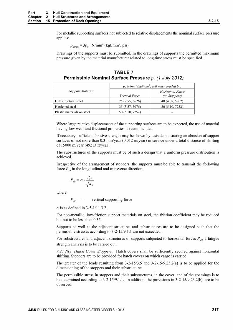
Part 3 Hull Construction and Equipment Chapter 2 Hull Structures and Arrangements Section 15 Protection of Deck Openings 3-2-15
ABS RULES FOR BUILDING AND CLASSING STEEL VESSELS . 2013 217
For metallic supporting surfaces not subjected to relative displacements the nominal surface pressure applies:
pnmax = 3pn N/mm2 (kgf/mm2, psi)
Drawings of the supports must be submitted. In the drawings of supports the permitted maximum pressure given by the material manufacturer related to long time stress must be specified.
TABLE 7 Permissible Nominal Surface Pressure pn (1 July 2012)
Support Material pn N/mm² (kgf/mm2, psi) when loaded by:
Vertical Force Horizontal Force
(on Stoppers) Hull structural steel 25 (2.55, 3626) 40 (4.08, 5802) Hardened steel 35 (3.57, 5076) 50 (5.10, 7252) Plastic materials on steel 50 (5.10, 7252) –
Where large relative displacements of the supporting surfaces are to be expected, the use of material having low wear and frictional properties is recommended.
If necessary, sufficient abrasive strength may be shown by tests demonstrating an abrasion of support surfaces of not more than 0.3 mm/year (0.012 in/year) in service under a total distance of shifting of 15000 m/year (49213 ft/year).
The substructures of the supports must be of such a design that a uniform pressure distribution is achieved.
Irrespective of the arrangement of stoppers, the supports must be able to transmit the following force Psh in the longitudinal and transverse direction:
Psh = h
sV
dP
⋅α
where
PsV = vertical supporting force
α is as defined in 3-5-1/11.3.2.
For non-metallic, low-friction support materials on steel, the friction coefficient may be reduced but not to be less than 0.35.
Supports as well as the adjacent structures and substructures are to be designed such that the permissible stresses according to 3-2-15/9.1.1 are not exceeded.
For substructures and adjacent structures of supports subjected to horizontal forces Psh, a fatigue strength analysis is to be carried out.
9.23.2(c) Hatch Cover Stoppers. Hatch covers shall be sufficiently secured against horizontal shifting. Stoppers are to be provided for hatch covers on which cargo is carried.
The greater of the loads resulting from 3-2-15/3.5 and 3-2-15/9.23.2(a) is to be applied for the dimensioning of the stoppers and their substructures.
The permissible stress in stoppers and their substructures, in the cover, and of the coamings is to be determined according to 3-2-15/9.1.1. In addition, the provisions in 3-2-15/9.23.2(b) are to be observed.
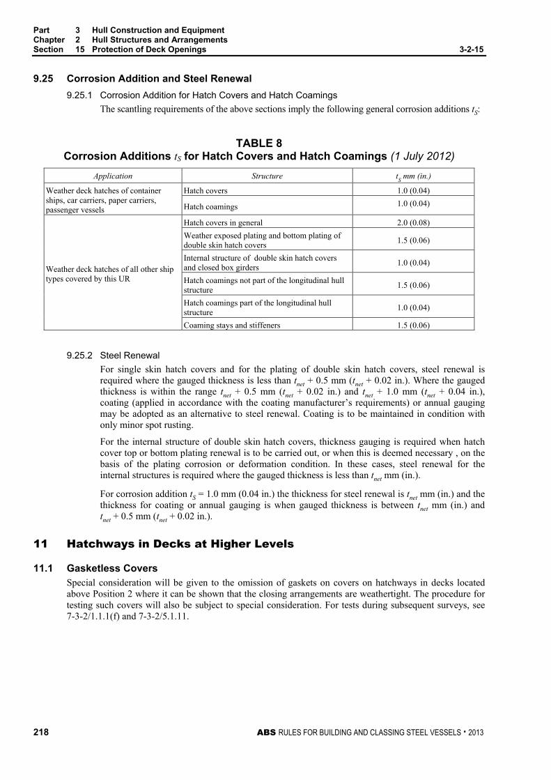
Part 3 Hull Construction and Equipment Chapter 2 Hull Structures and Arrangements Section 15 Protection of Deck Openings 3-2-15
218 ABS RULES FOR BUILDING AND CLASSING STEEL VESSELS . 2013
9.25 Corrosion Addition and Steel Renewal 9.25.1 Corrosion Addition for Hatch Covers and Hatch Coamings
The scantling requirements of the above sections imply the following general corrosion additions tS:
TABLE 8 Corrosion Additions tS for Hatch Covers and Hatch Coamings (1 July 2012)
Application Structure tS mm (in.)
Weather deck hatches of container ships, car carriers, paper carriers, passenger vessels
Hatch covers 1.0 (0.04)
Hatch coamings 1.0 (0.04)
Weather deck hatches of all other ship types covered by this UR
Hatch covers in general 2.0 (0.08) Weather exposed plating and bottom plating of double skin hatch covers 1.5 (0.06)
Internal structure of double skin hatch covers and closed box girders 1.0 (0.04)
Hatch coamings not part of the longitudinal hull structure 1.5 (0.06)
Hatch coamings part of the longitudinal hull structure 1.0 (0.04)
Coaming stays and stiffeners 1.5 (0.06)
9.25.2 Steel Renewal For single skin hatch covers and for the plating of double skin hatch covers, steel renewal is required where the gauged thickness is less than tnet + 0.5 mm (tnet + 0.02 in.). Where the gauged thickness is within the range tnet + 0.5 mm (tnet + 0.02 in.) and tnet + 1.0 mm (tnet + 0.04 in.), coating (applied in accordance with the coating manufacturer’s requirements) or annual gauging may be adopted as an alternative to steel renewal. Coating is to be maintained in condition with only minor spot rusting.
For the internal structure of double skin hatch covers, thickness gauging is required when hatch cover top or bottom plating renewal is to be carried out, or when this is deemed necessary , on the basis of the plating corrosion or deformation condition. In these cases, steel renewal for the internal structures is required where the gauged thickness is less than tnet mm (in.).
For corrosion addition tS = 1.0 mm (0.04 in.) the thickness for steel renewal is tnet mm (in.) and the thickness for coating or annual gauging is when gauged thickness is between tnet mm (in.) and tnet + 0.5 mm (tnet + 0.02 in.).
11 Hatchways in Decks at Higher Levels
11.1 Gasketless Covers Special consideration will be given to the omission of gaskets on covers on hatchways in decks located above Position 2 where it can be shown that the closing arrangements are weathertight. The procedure for testing such covers will also be subject to special consideration. For tests during subsequent surveys, see 7-3-2/1.1.1(f) and 7-3-2/5.1.11.

Part 3 Hull Construction and Equipment Chapter 2 Hull Structures and Arrangements Section 15 Protection of Deck Openings 3-2-15
ABS RULES FOR BUILDING AND CLASSING STEEL VESSELS . 2013 219
13 Hatchways in Lower Decks or within Fully Enclosed Superstructures
13.1 General The following scantlings are intended for ocean-going vessels and conventional type covers. Those scantlings for covers of special types or for vessels of restricted service are to be specially considered.
13.3 Beams and Wood Covers (1997) Hatchways in lower decks or within fully enclosed superstructures are to be framed with beams of sufficient strength. Where such hatches are intended to carry a load of cargo, the hatch beams are to have a section modulus SM not less than that obtained from the following equation:
SM = 7.8chs2 cm3
SM = 0.0041chs2 in3
where
c = 1.18
h = tween-deck height, in m (ft). When a design load is specified, h is to be taken as p/n where p is the specified design pressure, in kN/m2 (kgf/m2, lbf/ft2), and n is defined as 7.04 (715, 45).
s = spacing of hatch beams, in m (ft)
= length of hatch beams, in m (ft)
The wood covers are not to be less than 63.5 mm (2.50 in.) thick where the spacing of the beams does not exceed 1.52 m (5 ft). Where the height to which the cargo may be loaded on top of a hatch exceeds about 2.6 m (8.5 ft), or where the spacing of the beams exceeds 1.52 m (5 ft), the thickness of the wood covers is to be suitably increased.
13.5 Steel Covers Where steel covers are fitted, the thickness of the plating is to be not less than required for platform decks in enclosed cargo spaces as obtained from 3-2-3/5.1. A stiffening bar is to be fitted around the edges, as required, to provide the necessary rigidity to permit the covers being handled without deformation. The effective depth of the framework is normally to be not less than 4% of its unsupported length. Each stiffener in association with the plating to which it is attached is to have section modulus SM not less than that obtained from the following equation:
SM = 7.8hs2 cm3
SM = 0.0041hs2 in3
where
h = tween-deck height, in m (ft). When a design load is specified, h is to be taken as p/n where p is the specified design pressure, in kN/m2 (kgf/m2, lbf/ft2), and n is defined as 7.04 (715, 45).
s = spacing of the stiffeners, in m (ft)
= length of the stiffener, in m (ft)
13.7 Wheel Loading Where provision is to be made for the operation or stowage of vehicles having rubber tires, the thickness of the hatch cover plating is to be not less than obtained from 3-2-3/5.17, for platform deck plating, except that the thickness of plate panels adjacent to the edges of the covers is to be at least 15% greater than obtained from 3-2-3/5.17.

Part 3 Hull Construction and Equipment Chapter 2 Hull Structures and Arrangements Section 15 Protection of Deck Openings 3-2-15
220 ABS RULES FOR BUILDING AND CLASSING STEEL VESSELS . 2013
14 Small Hatches on the Exposed Fore Deck (2004)
14.1 Application
The requirements of this subsection apply to all small hatches [opening normally 2.5 m2 (27 ft2) or less] located on the exposed fore deck within the forward 0.25L, where the deck in way of the hatch is less than 0.1L or 22 m (72.2 ft) above the summer load line, whichever is less.
Hatches designed for emergency escape need not comply with 3-2-15/14.5i), 3-2-15/14.5ii), the third paragraph of 3-2-15/14.7 and 3-2-15/14.9.
14.3 Strength For small rectangular steel hatch covers, the plate thickness, stiffener arrangement and scantlings are to be in accordance with 3-2-15/Table 9 and 3-2-15/Figure 12. Stiffeners, where fitted, are to be aligned with the metal-to-metal contact points required in 3-2-15/14.7 (see also 3-2-15/Figure 12). Primary stiffeners are to be continuous. All stiffeners are to be welded to the inner edge stiffener (see 3-2-15/ Figure 13).
The upper edge of the hatchway coaming is to be suitably reinforced by a horizontal section, normally not more than 170 to 190 mm (6.9 to 7.5 in.) from the upper edge of the coaming.
For small hatch covers of circular or similar shape, the cover plate thickness and reinforcement is to provide strength and stiffness equivalent to the requirements for small rectangular hatches.
For small hatch covers constructed of materials other than steel, the required scantlings are to provide strength and stiffness equivalent to 235 N/mm2 (24 kgf/mm2, 34,000 psi) yield strength steel.
14.5 Primary Securing Devices The primary securing devices are to be such that their hatch covers can be secured in place and made weathertight by means of a mechanism employing any one of the following methods:
i) Butterfly nuts tightening onto forks (clamps), or
ii) Quick acting cleats, or
iii) A central locking device.
Dogs (twist tightening handles) with wedges are not acceptable.
14.7 Requirements for Primary Securing The hatch cover is to be fitted with a gasket of elastic material. This is to be designed to allow a metal-to-metal contact at a designed compression and to prevent over compression of the gasket by green sea forces that may cause the securing devices to be loosened or dislodged. The metal-to-metal contacts are to be arranged close to each securing device, in accordance with 3-2-15/Figure 12, and of sufficient capacity to withstand the bearing force.
The primary securing method is to be designed and manufactured such that the designed compression pressure is achieved by one person without the need of any tools.
For a primary securing method using butterfly nuts, the forks (clamps) are to be of robust design. They are to be designed to minimize the risk of butterfly nuts being dislodged while in use, by means of curving the forks upward and a raised surface on the free end, or a similar method. The plate thickness of unstiffened steel forks is not to be less than 16 mm (5/8 in.). An example arrangement is shown in 3-2-15/Figure 13.
For small hatch covers located on the exposed deck forward of the fore-most cargo hatch, the hinges are to be fitted such that the predominant direction of green sea will cause the cover to close, which means that the hinges are normally to be located on the fore edge.
On small hatches located between the main hatches, for example, between Nos. 1 and 2, the hinges are to be placed on the fore edge or outboard edge, whichever is practicable for protection from green water in beam sea and bow quartering conditions.

Part 3 Hull Construction and Equipment Chapter 2 Hull Structures and Arrangements Section 15 Protection of Deck Openings 3-2-15
ABS RULES FOR BUILDING AND CLASSING STEEL VESSELS . 2013 221
14.9 Secondary Devices Small hatches on the fore deck are to be fitted with an independent secondary securing device, e.g., by means of a sliding bolt, a hasp or a backing bar of slack fit, which is capable of keeping the hatch cover in place even in the event that the primary securing device became loosened or dislodged. It is to be fitted on the side opposite to the hatch cover hinges.
TABLE 9 Scantlings for Small Steel Hatch Covers on the Fore Deck
Nominal Size (mm × mm)
Cover Plate Thickness (mm)
Primary Stiffeners Secondary Stiffeners Flat Bar (mm × mm); number
630 × 630 8 --- ---
630 × 830 8 100 × 8; 1 ---
830 × 630 8 100 × 8; 1 ---
830 × 830 8 100 × 10; 1 ---
1030 × 1030 8 120 × 12; 1 80 × 8; 2 1330 × 1330 8 150 × 12; 2 100 × 10; 2

Part 3 Hull Construction and Equipment Chapter 2 Hull Structures and Arrangements Section 15 Protection of Deck Openings 3-2-15
222 ABS RULES FOR BUILDING AND CLASSING STEEL VESSELS . 2013
FIGURE 12 Arrangement of Stiffeners (2004)
Nominal size 630 × 630 Nominal size 630 × 830
Nominal size 830 × 830 Nominal size 830 × 630
Nominal size 1030 × 1030 Nominal size 1330 × 1330
Hinge
Securing device/metal to metal contact
Primary stiffener
Secondary stiffener

Part 3 Hull Construction and Equipment Chapter 2 Hull Structures and Arrangements Section 15 Protection of Deck Openings 3-2-15
ABS RULES FOR BUILDING AND CLASSING STEEL VESSELS . 2013 223
FIGURE 13 Example of Primary Securing Method (2004)
M20
1
5 (min. 16 mm)
6
29
3
4
φ20
11
810
7
1: butterfly nut2: bolt3: pin4: center of pin5: fork (clamp) plate6: hatch cover7: gasket8: hatch coaming9: bearing pad welded on the bracket of a toggle bolt for metal to metal contact10: stiffener11: inner edge stiffener
(Note: Dimensions in millimeters)
15 Other Hatchways
15.1 Hatchways within Open Superstructures Hatchways within open superstructures are to be considered as exposed.
15.3 Hatchways within Deckhouses Hatchways within deckhouses are to have coamings and closing arrangements as required in relation to the protection afforded by the deckhouse from the standpoint of its construction and the means provided for the closing of all openings into the house.

Part 3 Hull Construction and Equipment Chapter 2 Hull Structures and Arrangements Section 15 Protection of Deck Openings 3-2-15
224 ABS RULES FOR BUILDING AND CLASSING STEEL VESSELS . 2013
17 Additional Requirements for Subdivision
17.1 External Opening below Damage Waterline All external openings leading to compartments assumed intact in the damage analysis, which are permitted by 3-3-1/3.3 to be below the final damage waterline, are to be watertight. Except for hatch covers, these openings are to be fitted with indicators on the bridge showing whether the closing appliances are open or closed.
17.3 Internal Openings The openings and penetrations in internal decks required to be watertight for subdivision are to meet the corresponding requirements for watertight doors in 3-2-9/1.3 and 3-2-9/9.
19 Machinery Casings
19.1 Arrangement (2002) Machinery-space openings in Position 1 or 2 are to be framed and efficiently enclosed by steel casings of ample strength, and, wherever practicable, those in freeboard decks are to be within superstructures or deckhouses. Where the machinery casings are exposed, plating and stiffeners are to be in accordance with the requirements in 3-2-11/3. Access openings in exposed casings are to be fitted with doors complying with the requirements of 3-2-11/5.3, the sills of which are to be at least 600 mm (23.5 in.) above the deck if in Position 1, and at least 380 mm (15 in.) above the deck if in Position 2. Where the vessel is assigned a freeboard less than that based on Table B as allowed by the International Convention on Load Lines, 1966, there are generally to be no openings giving direct access from the freeboard deck to the machinery space. A door, complying with the requirements of 3-2-11/5.3, may however be permitted in the exposed machinery casing, provided that it leads to a space or passageway that is as strongly constructed as the casing and is separated from the engine room by a second door complying with 3-2-11/5.3. The sill of the exterior door is not to be less than 600 mm (23.5 in.), and the sill of the second/interior door is to be not less than 230 mm (9 in.). Other openings in such casings are to be fitted with equivalent covers, permanently attached in their proper positions. See also 4-7-2/1.9.5 and 4-7-2/1.9.6.
19.3 Fiddleys, Funnels, and Ventilators Coamings of any fiddley, funnel or machinery-space ventilator in an exposed position on the freeboard or superstructure deck are to be as high above the deck as is reasonable and practicable. Fiddley openings are to be fitted with strong covers of steel or other equivalent material, permanently attached in their proper positions and capable of being secured weathertight.
19.5 Casings within Open Superstructures (2002) Casings within open superstructures are to be of similar scantlings to those obtained from 3-2-11/3 for exposed casings on superstructure decks. Where there are no end bulkheads to the superstructures, the arrangements and scantlings are to be in compliance with 3-2-11/3 for an exposed casing on the freeboard deck.
19.7 Casings within Enclosed Superstructures (2002) The thickness of casings within enclosed superstructures is to be not less than obtained from the following equation:
t = 4.6 + L/64 + (s – 760)/150 mm but not less than 6.0 mm
t = 0.146 + L/3500 + (s – 30)/150 in. but not less than 0.23 in.
The thickness of casing sides in accommodation spaces above the crown of the machinery space is not to be less than obtained from the following equation:
t = 4.5 + (s – 760)/150 mm
t = 0.18 + (s – 30)/150 in.
Part 3 Hull Construction and Equipment Chapter 2 Hull Structures and Arrangements Section 15 Protection of Deck Openings 3-2-15
ABS RULES FOR BUILDING AND CLASSING STEEL VESSELS . 2013 225
where
L = length of vessel, as defined in 3-1-1/3.1, in m (ft) but need not be taken greater than 122 m (400 ft)
s = the stiffener spacing, in mm (in.), but is not to be taken less than 760 mm (30 in.)
Where accelerated corrosion is expected, such as in way of wet spaces, the thickness of coaming plates may need to be increased. Where casings are used in lieu of girders or deep beams, the plating in way is to be suitably increased. Stiffeners are to be fitted in line with the beams and are to have a section modulus SM not less than obtained from the following equation:
SM = 7.8chs2 cm3
SM = 0.0041chs2 in3
where
c = 0.14
s = spacing of stiffeners, in m (ft)
h = tween-deck height, in m (ft)
= length, between support, of the stiffeners, in m (ft)
Casings which support girders or pillars are to be suitably stiffened in such manner as to provide supports not less effective than required for stanchions or pillars.
19.9 Casings within Deckhouses Casings within deckhouses are to have scantlings, sill heights and closing arrangements to entrances as required in relation to the protection offered by the deckhouse from the standpoint of its construction and the means for closing all openings into the house.
21 Miscellaneous Openings in Freeboard and Superstructure Decks
21.1 Manholes and Scuttles Manholes and flush scuttles in Position 1 or 2 or within superstructures other than enclosed superstructures are to be closed by substantial covers capable of being made watertight. Unless secured by closely spaced bolts, the covers are to be permanently attached.
21.3 Other Openings Openings in freeboard decks other than hatchways, machinery-space openings, manholes and flush scuttles are to be protected by an enclosed superstructure, or by a deckhouse or companionway of equivalent strength and weathertightness. Any such opening in an exposed superstructure deck or in the top of a deckhouse on the freeboard deck which gives access to a space below the freeboard deck or a space within an enclosed superstructure is to be protected by an efficient deckhouse or companionway. Doorways in such deckhouses or companionways are to be fitted with doors complying with the requirements of 3-2-11/5.3.
21.5 Escape Openings (1 July 2012) i) The closing appliances of escape openings are to be of a type that is operable from each side.
ii) The maximum force needed to open the hatch cover is not to exceed 150 N (15.3 kgf, 33.7 lbf).
iii) The use of a spring equalizing, counterbalance or other suitable device on the hinge side to reduce the force needed for opening is acceptable.
21.7 Companionway Sills In Position 1, the height above the deck of sills to the doorways in companionways is to be at least 600 mm (23.5 in.). In Position 2, they are to be at least 380 mm (15 in.).

Part 3 Hull Construction and Equipment Chapter 2 Hull Structures and Arrangements Section 15 Protection of Deck Openings 3-2-15
226 ABS RULES FOR BUILDING AND CLASSING STEEL VESSELS . 2013
21.9 Mast Openings Openings penetrating decks and other structures to accommodate masts, kingposts and similar members are to be reinforced by fitting doublings or plating of increased thickness.
21.11 Chain Pipe Opening (1 July 2012) Chain pipes through which anchor cables are led are to be provided with permanently attached closing appliances to minimize the ingress of water. A canvas cover with appropriate lashing arrangement will be acceptable(1) for this purpose. A cement and wire mesh arrangement is not permitted.
The arrangement on vessels that are not subject to the International Convention on Load Lines or its Protocol may be specially considered. Note(1)
:
Examples of acceptable arrangements are such as:
i) Steel plates with cutouts to accommodate chain links or
ii) Canvas hoods with a lashing arrangement that maintains the cover in the secured position.

ABS RULES FOR BUILDING AND CLASSING STEEL VESSELS . 2013 227
P A R T Appendix 6: Portable Beams and Hatch Cover Stiffeners of Variable Cross Section
3 C H A P T E R 2 Hull Structures and Arrangements
A P P E N D I X 6 Portable Beams and Hatch Cover Stiffeners of Variable Cross Section (1997)
1 Application For portable beams and hatch cover stiffeners with free ends and varying cross section along their span, the section modulus SM and inertia I at the midspan required by 3-2-15/7.1.1, 3-2-15/7.3.2, 3-2-15/7.5.1 and 3-2-15/9.1 may be obtained from the following equations.
SM = a
psKCσ
211
cm3 (in3)
I = C2K2 ps3 cm4 (in4)
where
C1 = 125 (125, 1.5)
C2 = 2.87 (28.2, 2.85 × 10⁻⁵) for 3-2-15/7.1.1 and 3-2-15/7.3.2
= 2.26 (22.1, 2.24 × 10⁻⁵) for 3-2-15/7.5.1 and 3-2-15/9.1
K1 = 0.47
0.83.21
+−−
+γ
γα , but not less than 1.0
α = length ratio
= 1/
γ = SM ratio
= SM1 /SM
1, , SM1 and SM are as indicated in 3-2-A6/Figure 1.
σa = allowable stress given in 3-2-15/7.1.1, 3-2-15/7.3.2, 3-2-15/7.5.1 and 3-2-15/9.1, in kN/mm2 (kgf/mm2, psi)
K2 = 1 + 8α3
)30.2()1(β
β+
− , but not less than 1.0
β = ratio of the moments of inertia, I1 and I, at the locations indicated in 3-2-A6/Figure 1
= I1/I
p = design load given in 3-2-15/3.3, in kN/m2 (tf/m2, psi)
s = spacing of beams or stiffeners, in m (ft).
= span of free ended constructional elements, in m (ft).

Part 3 Hull Construction and Equipment Chapter 2 Hull Structures and Arrangements Appendix 6 Portable Beams and Hatch Cover Stiffeners of Variable Cross Section 3-2-A6
228 ABS RULES FOR BUILDING AND CLASSING STEEL VESSELS . 2013
FIGURE 1 SM and I of Construction Elements
1
SM ISM1 I1

ABS RULES FOR BUILDING AND CLASSING STEEL VESSELS . 2013 229
P A R T S e c t i o n 1 6 : P r o t e c t i o n o f S h e l l O p e n i n g s
3 C H A P T E R 2 Hull Structures and Arrangements
S E C T I O N 16 Protection of Shell Openings
1 Cargo, Gangway, or Fueling Ports
1.1 Construction (1997) Cargo, gangway, or fueling ports in the sides of vessels are to be strongly constructed and capable of being made thoroughly watertight. Where frames are cut in way of such ports, web frames are to be fitted on each side of the opening and suitable arrangements are to be provided for the support of the beams over the opening. Shell doublings are to be fitted, as required, to compensate for the openings, and the corners of the openings are to be well rounded. Waterway angles and scuppers are to be provided on the deck in way of openings in cargo spaces below the freeboard deck or in cargo spaces within enclosed superstructures to prevent the spread of any leakage water over the deck.
Indicators showing whether the ports in the side shell below the freeboard or superstructure deck are secured closed or open are to be provided on the navigation bridge.
Where allowed by 3-2-16/1.3, cargo ports or similar openings located with their lower edge below the line defined in 3-2-16/1.3 are to be fitted with a second door of equivalent strength and watertightness with a leakage detection device for the compartment between the doors. The drain from this compartment is to be led to the bilge with a screwdown valve operable from an accessible location.
In general, all outer doors are to open outwards.
1.3 Location (1997) Unless especially approved, the lower edge of cargo, gangway, or fueling port openings is not to be below a line drawn parallel to the freeboard deck at side, which has at its lowest point the upper edge of the uppermost load line.
Cargo ports or similar openings may be located with their lower edge below the above defined line, provided they meet the additional construction requirements of 3-2-16/1.1.
1.5 Subdivision Requirements Openings in the shell plating below the deck, limiting the vertical extent of damage, are to be kept permanently closed while at sea. Should any of these openings be accessible during the voyage, their closing appliances are to be fitted with a device which prevents unauthorized opening.
Closing appliances which are kept permanently closed at sea to ensure the watertight integrity of external openings but are not fitted with a device which prevents unauthorized opening, due to their inaccessibility during the voyage, are to be provided with a notice affixed to each such closing appliance to the effect that it is to be kept closed.
Part 3 Hull Construction and Equipment Chapter 2 Hull Structures and Arrangements Section 16 Protection of Shell Openings 3-2-16
230 ABS RULES FOR BUILDING AND CLASSING STEEL VESSELS . 2013
3 Bow Doors, Inner Doors, Side Shell Doors and Stern Doors (1998)
3.1 General (2005) Where bow doors of the visor or side-opening type are fitted leading to complete or long forward enclosed superstructures, or to long superstructures with closing appliances to the satisfaction of the Administration, bow doors and inner doors are to meet the requirements of this section. Hull supporting structure in way of the bow doors is to be able to withstand the loads imposed by the bow door securing and supporting devices without exceeding the allowable stresses for those devices, both given in this section.
Side shell doors fitted abaft of the collision bulkhead and stern doors leading into enclosed spaces are to meet the requirements of this section.
3.3 Arrangement 3.3.1 General
As far as practicable, bow doors and inner doors are to be arranged so as to preclude the possibility of the bow door causing structural damage to the inner door or to the collision bulkhead in the case of damage to or detachment of the bow door.
3.3.2 Bow Doors Bow doors are to be situated above the freeboard deck, except that where a watertight recess fitted for arrangement of ramps or other related mechanical devices is located forward of the collision bulkhead and above the deepest waterline, the bow doors may be situated above the recess.
3.3.3 Inner Doors An inner door is to be fitted in the extension of the collision bulkhead required by 3-2-9/3.1.1. A vehicle ramp made watertight and conforming to 3-2-9/Figure 1 in the closed position may be accepted for this purpose.
3.3.4 Side Shell and Stern Doors (1998) Stern doors for passenger vessels are to be situated above the freeboard deck. Stern doors for ro-ro cargo vessels and all side shell doors need not be situated above the freeboard deck.
5 Securing, Locking and Supporting of Doors
5.1 Definitions 5.1.1 Securing Device
A device used to keep the door closed by preventing it from rotating about its hinges or its pivoted attachments to the vessel.
5.1.2 Supporting Device A device used to transmit external or internal loads from the door to a securing device and from the securing device to the vessel’s structure, or a device other than a securing device, such as a hinge, stopper or other fixed device, that transmits loads from the door to the vessel’s structure.
5.1.3 Locking Device A device that locks a securing device in the closed position.

Part 3 Hull Construction and Equipment Chapter 2 Hull Structures and Arrangements Section 16 Protection of Shell Openings 3-2-16
ABS RULES FOR BUILDING AND CLASSING STEEL VESSELS . 2013 231
7 Securing and Supporting Devices (1998)
7.1 General Securing and supporting devices are to be arranged in accordance with this subsection, and are to have scantlings as required by 3-2-16/13.9, 3-2-16/15.5 or 3-2-16/17.9, as appropriate.
7.3 Bow Doors Means are to be provided to prevent lateral or vertical movement of the bow doors when closed. Means are also to be provided for mechanically fixing the door in the open position.
Means of securing and supporting the door are to maintain equivalent strength and stiffness of the adjacent structure.
7.3.1 Clearance and Packing The maximum design clearance between the door and securing/supporting devices is not to exceed 3 mm (0.12 in.). Where packing is fitted, it is to be of a comparatively soft type and the supporting forces are to be carried by the steel structure only.
7.3.2 Visor Door Arrangement The pivot arrangement is to be such that the visor is self-closing under external loads. The closing moment, My, as defined in 3-2-16/19.5.1, is not to be less than Myo, as given by the following equation:
Myo = Wc + 0.1 2222zx FFba ++
where W, a, b, c, Fx and Fz are as defined in 3-2-16/17.
In addition, the arrangement of the door is to be such that the reaction forces of pin or wedge supports at the base of the door does not act in the forward direction when the door is loaded in accordance with 3-2-16/19.5.4.
7.5 Side Shell and Stern Doors (1998) Means are to be provided to prevent lateral or vertical movement of the side shell or stern doors when closed. Means are also to be provided for mechanically fixing the doors in the open position.
The means of securing and supporting the doors are to have strength and stiffness equivalent to the adjacent structure.
Clearance and packing for side shell and stern doors are to be in accordance with 3-2-16/7.3.1.
9 Securing and Locking Arrangement
9.1 General Securing devices are to be provided with a mechanical locking arrangement (self-locking or separate arrangement), or are to be of the gravity type.
9.3 Operation Securing devices are to be simple to operate and readily accessible. The opening and closing systems as well as the securing and locking devices are to be interlocked in such a way that they can only operate in the proper sequence.

Part 3 Hull Construction and Equipment Chapter 2 Hull Structures and Arrangements Section 16 Protection of Shell Openings 3-2-16
232 ABS RULES FOR BUILDING AND CLASSING STEEL VESSELS . 2013
11 Tightness
11.1 Bow Doors Bow doors are to be so fitted as to ensure tightness consistent with operational conditions and to give effective protection to the inner doors.
11.3 Inner Doors Inner doors forming part of the extension of the collision bulkhead are to be weathertight over the full height of the cargo space and arranged with fixed sealing supports on the aft side of the doors.
11.5 Side Shell and Stern Doors (1998) Side shell doors and stern doors are to be so fitted as to ensure water tightness.
13 Bow Door Scantlings
13.1 General Bow doors are to be framed and stiffened so that the whole structure is equivalent to the intact bow structure when closed.
13.3 Primary Structure (2005) Scantlings of primary members are to be designed so that the allowable stresses indicated in 3-2-16/25.1 are not exceeded when the structure is subjected to the design loads indicated in 3-2-16/19.1. Normally, simple beam theory may be applied to determine the bending stresses. Members are to be considered to have simply supported end connections.
13.5 Secondary Stiffeners Secondary stiffeners are to be supported by primary members constituting the main stiffening of the door. The section modulus, SM, of secondary stiffeners is to be as required in 3-2-5/1.1 and 3-2-5/5. Consideration is to be given, where necessary, to differences in fixity between the requirements in 3-2-5/1.1, 3-2-5/5, and bow door stiffeners.
In addition, stiffener webs are to have a net sectional area not less than that obtained from the following equation:
A = VQ /10 cm2 (A = VQ cm2, A = VQ /6.5 in2 )
where
V = shear force, in kN (tf, Ltf), in the stiffener calculated using the uniformly distributed external pressure, Peb, given in 3-2-16/19.1
Q = as defined in 3-2-1/5.5
13.7 Plating The thickness of bow door plating is to be not less than that required for side shell plating at the same location.
13.9 Securing and Supporting Devices (2005) Scantlings of securing and supporting devices are to be designed so that the allowable stresses indicated in 3-2-16/25.1 are not exceeded when the structure is subjected to the design loads indicated in 3-2-16/19.3. All load-transmitting elements in the design load path from the door through securing and supporting devices into the vessel structure, including welded connections, are to meet the strength standards required for securing and supporting devices. These elements include pins, support brackets and back-up brackets. Where fitted, threaded bolts are not to carry support forces, and the maximum tensile stress in way of the threads is not to exceed the allowable stress given in 3-2-16/25.5.

Part 3 Hull Construction and Equipment Chapter 2 Hull Structures and Arrangements Section 16 Protection of Shell Openings 3-2-16
ABS RULES FOR BUILDING AND CLASSING STEEL VESSELS . 2013 233
In determining the required scantlings, the door is to be assumed to be a rigid body. Only those active supporting and securing devices having an effective stiffness in the relevant direction are to be included and considered when calculating the reaction forces on the devices. Small or flexible devices such as cleats intended to provide compression load on the packing material are not to be included in the calculations.
13.9.1 Bearing Pressure The bearing pressure on steel to steel bearings is to be calculated by dividing the design force by the projected bearing area, and is not to exceed the allowable stress given in 3-2-16/25.3.
13.9.2 Redundancy In addition to the above requirements, the arrangement of the securing and supporting devices is to be designed with redundancy such that in the event of failure of any single securing or supporting device, the stresses in the remaining devices do not exceed the allowable stresses indicated in 3-2-16/25.1 by more than 20% under the above loads.
13.9.3 Visor Door Securing and Supporting Devices Securing and supporting devices, excluding the hinges, are to be capable of resisting the vertical design force given in 3-2-16/19.5.3 without exceeding the allowable stresses in 3-2-16/25.1.
Two securing devices are to be provided at the lower part of the door, each capable of providing the full reaction force required to prevent opening of the door without stresses exceeding the allowable stresses indicated in 3-2-16/25.1. The opening moment, Mo, to be balanced by this force is as given in 3-2-16/19.5.2.
13.9.4 Side-opening Door Thrust Bearing A thrust bearing is to be provided in way of girder ends at the closing of the two doors, and is to prevent one door from shifting towards the other one under the effect of unsymmetrical pressure. Securing devices are to be fitted to secure sections thrust bearing to one another.
13.11 Visor Door Lifting Arms and Supports Where visor type bow doors are fitted, calculations are to be submitted verifying that lifting arms and their connections to the door and vessel structure are adequate to withstand the static and dynamic forces applied during the lifting and lowering operations under a wind pressure of at least 1.5 kN/m2 (0.15 tf/m2, 0.014 Ltf/ft2 ).
15 Inner Door Scantlings
15.1 General Scantlings of inner doors are to meet the requirements of this subsection. In addition, where inner doors are used as vehicle ramps, scantlings are not to be less than required for vehicle decks in Section 3-2-3, Section 3-2-7 and Section 3-2-8.
15.3 Primary Structure Scantlings of primary members are to be designed so that the allowable stresses indicated in 3-2-16/25.1 are not exceeded when the structure is subjected to the design loads indicated in 3-2-16/21.1.
15.5 Securing and Supporting Devices Scantlings of securing and supporting devices are to be designed so that the allowable stresses indicated in 3-2-16/25.1 are not exceeded when the structure is subjected to the design loads indicated in 3-2-16/21. Where fitted, threaded bolts are not to carry support forces, and the maximum tensile stress in way of the threads is not to exceed the allowable stress given in 3-2-16/25.5.
The bearing pressure on steel to steel bearings is to be calculated by dividing the design force by the projected bearing area, and is not to exceed the allowable stress given in 3-2-16/25.3.

Part 3 Hull Construction and Equipment Chapter 2 Hull Structures and Arrangements Section 16 Protection of Shell Openings 3-2-16
234 ABS RULES FOR BUILDING AND CLASSING STEEL VESSELS . 2013
17 Side Shell Door and Stern Door Scantlings (1998)
17.1 General Scantlings of side shell doors or stern doors are to meet the requirements of this subsection. In addition, where the doors are used as vehicle ramps, scantlings are not to be less than required for vehicle decks in Section 3-2-3, Section 3-2-7 and Section 3-2-8.
17.3 Primary Structure (2005) Scantlings of primary members are to be designed so that the allowable stresses indicated in 3-2-16/25.1 are not exceeded when the structure is subjected to the design loads indicated in 3-2-16/23. Normally, simple beam theory may be applied to determine the bending stresses. Members are considered to have simply supported end connections.
17.5 Secondary Stiffeners Secondary stiffeners are to be supported by primary members constituting the main stiffening of the door. The section modulus, SM, of secondary stiffeners is to be not less than required by Section 3-2-5 for frames in the same location. In addition, the net sectional area of stiffener webs is to be in accordance with 3-2-16/13.5, using the external pressure, pe, given in 3-2-16/23.
17.7 Plating The thickness of side or stern door plating is to be not less than that required for side shell plating at the same location.
17.9 Securing and Supporting Devices Scantlings of securing and supporting devices are to be designed so that the allowable stresses indicated in 3-2-16/25.1 are not exceeded when the structure is subjected to the design loads indicated in 3-2-16/23. All load-transmitting elements in the design load path from the door through securing and supporting devices into the vessel structure, including welded connections, are to meet the strength standards required for securing and supporting devices. Where fitted, threaded bolts are not to carry support forces, and the maximum tensile stress in way of the threads is not to exceed the allowable stress given in 3-2-16/25.5.
In determining the required scantlings, the door is to be assumed to be a rigid body. Only those active supporting and securing devices having an effective stiffness in the relevant direction are to be included and considered when calculating the reaction forces on the devices. Small or flexible devices such as cleats intended to provide compression load on the packing material are not to be included in the calculations.
17.9.1 Bearing Pressure The bearing pressure on steel-to-steel bearings is to be calculated by dividing the design force by the projected bearing area, and is not to exceed the allowable stress given in 3-2-16/25.3.
17.9.2 Redundancy In addition to the above requirements, the arrangement of the securing and supporting devices is to be designed with redundancy such that in the event of a failure of any single securing or supporting device, the stresses in the remaining devices do not exceed the allowable stresses indicated in 3-2-16/25.1 by more than 20% under the above loads.

Part 3 Hull Construction and Equipment Chapter 2 Hull Structures and Arrangements Section 16 Protection of Shell Openings 3-2-16
ABS RULES FOR BUILDING AND CLASSING STEEL VESSELS . 2013 235
19 Bow Door Design Loads
19.1 External Pressure The design external pressure, Peb , is to be taken as indicated by the following equation:
Peb = nc (0.22 + 0.15 tan β) (0.4Vd sin α + 0.6 1kL )2 kN/m2 (tf/m2, Ltf/ft2)
where
n = 2.75 (0.280, 0.0256)
c = 1.0
L = length of vessel, as defined in 3-1-1/3.1, in m (ft).
L1 = length of vessel, in m (ft), as defined in 3-1-1/3.1, but need not be taken as greater than 200 m (656 ft.)
β = flare angle at the point to be considered, defined as the angle between a vertical line and the tangent to the side shell plating measured in a vertical plane normal to the horizontal tangent to the shell plating. See 3-2-16/Figure 1.
α = entry angle at the point to be considered, defined as the angle between a longitudinal line parallel to the centerline and the tangent to the shell plating in a horizontal plane. See 3-2-16/Figure 1.
k = 1.0 (1.0, 0.305)
Vd = vessel design speed, as defined in 3-2-14/3.1.
FIGURE 1 Entry and Flare Angles
Section A - A
Section B - B
A A
B
B
ß
α

Part 3 Hull Construction and Equipment Chapter 2 Hull Structures and Arrangements Section 16 Protection of Shell Openings 3-2-16
236 ABS RULES FOR BUILDING AND CLASSING STEEL VESSELS . 2013
19.3 External Forces (2005) The design external forces considered in determining scantlings of securing and supporting devices of bow doors are not to be taken less than those given by the following equations:
Fx = PemAx
Fy = PemAy
Fz = PemAz
where
Fx = the design external force in the longitudinal direction, in kN (tf, Ltf)
Fy = the design external force in the horizontal direction, in kN (tf, Ltf)
Fz = the design external force in the vertical direction, in kN (tf, Ltf)
Ax = area, in m2 (ft2), of the transverse projection of the door between the levels of the bottom of the door and the top of the upper deck bulwark or between the bottom of the door and the top of the door, whichever is the lesser. Where the flare angle of the bulwark is at least 15° less than the flare of the adjacent shell plating, the bulwark may be excluded and the distance may be measured from the bottom of the door to the upper deck or to the top of the door, whichever is the lesser.
Ay = area, in m2 (ft2), of the longitudinal projection of the door between the levels of the bottom of the door and the top of the upper deck bulwark or between the bottom of the door and the top of the door, whichever is the lesser. Where the flare angle of the bulwark is at least 15º less than the flare of the adjacent shell plating, the bulwark may be excluded and the distance may be measured from the bottom of the door to the upper deck or to the top of the door, whichever is the lesser.
Az = area, in m2 (ft2), of the horizontal projection of the door between the levels of the bottom of the door and the top of the upper deck bulwark or between the bottom of the door and the top of the door, whichever is the lesser. Where the flare angle of the bulwark is at least 15º less than the flare of the adjacent shell plating, the bulwark may be excluded and the distance may be measured from the bottom of the door to the upper deck or to the top of the door, whichever is the lesser.
Pem = bow door pressure, Peb, determined using αm and βm in place of α and β
βm = flare angle measured at a point on the bow door /2 aft of the stem line on a plane h/2 above the bottom of the door as shown in 3-2-16/Figure 2
αm = entry angle measured at the same point as βm. See 3-2-16/Figure 2
h = height, in m (ft), of the door between the levels of the bottom of the door and the upper deck or between the bottom of the door and the top of the door, whichever is less
= fore and aft length, in m (ft), of the door at a height h/2 above the bottom of the door

Part 3 Hull Construction and Equipment Chapter 2 Hull Structures and Arrangements Section 16 Protection of Shell Openings 3-2-16
ABS RULES FOR BUILDING AND CLASSING STEEL VESSELS . 2013 237
FIGURE 2 Definition of αm and βm
AA
Section B - B
Section A - A
B
B
α m
ßm
/2 /2
h/2
h/2
19.5 Visor Door Forces, Moments and Load Cases 19.5.1 Closing Moment
For visor doors, the closing moment, My, is to be taken as indicated by the following equation:
My = Fx a + Wc − Fz b kN-m (tf-m, Ltf-ft)
where
W = weight of the visor door, in kN (tf, Ltf)
a = vertical distance, in m (ft), from the visor pivot to the centroid of the transverse vertical projected area of the visor door. See 3-2-16/Figure 3.
b = horizontal distance, in m (ft.), from visor pivot to the centroid of the horizontal projected area of the visor door. See 3-2-16/Figure 3.
c = horizontal distance, in m (ft.), from the visor pivot to the center of gravity of the visor. See 3-2-16/Figure 3.
Fx and Fz are as defined in 3-2-16/19.3.

Part 3 Hull Construction and Equipment Chapter 2 Hull Structures and Arrangements Section 16 Protection of Shell Openings 3-2-16
238 ABS RULES FOR BUILDING AND CLASSING STEEL VESSELS . 2013
FIGURE 3 Visor Type Bow Door
Elevation Front View
Plan View
AxAy
Z
Az
XCL
LC
W d
b
c
a
CG
19.5.2 Opening Moment The opening moment, Mo, is to be taken as indicated by the following equation:
Mo = Wd + 5Ax a kN-m (Wd + 0.5Ax a tf-m, Wd + 0.047Ax a Ltf-ft)
where
d = vertical distance, in m (ft), from the hinge axis to the center of gravity of the door
W, Ax and a are as indicated above.
19.5.3 Vertical Design Force The vertical design force is to be taken as Fz − W where Fz is as defined in 3-2-16/19.3 and W is as defined in 3-2-16/19.5.1.
19.5.4 Combined Load Case 1 The visor doors are to be evaluated under a load of Fx, Fz and W acting simultaneously with Fx and Fz acting at the centroid of their respective projected areas.
19.5.5 Combined Load Case 2 The visor doors are to be evaluated under a load of 0.7Fy acting on each side separately, together with 0.7Fx, 0.7Fz and W. Fx, Fy and Fz are to be taken as acting at the centroid of their of their respective projected areas.

Part 3 Hull Construction and Equipment Chapter 2 Hull Structures and Arrangements Section 16 Protection of Shell Openings 3-2-16
ABS RULES FOR BUILDING AND CLASSING STEEL VESSELS . 2013 239
19.7 Side-Opening Door Load Cases 19.7.1 Combined Load Case 1
Side opening doors are to be evaluated under a load of Fx, Fy, Fz and W acting simultaneously with Fx, Fy and Fz acting at the centroid of their respective projected areas.
19.7.2 Combined Load Case 2 Side opening doors are to be evaluated under a load of 0.7Fx, 0.7Fx and W acting on both doors simultaneously and 0.7Fy acting on each door separately.
21 Inner Door Design Loads
21.1 External Pressure The design external pressure is to be taken as the greater of Pei or Ph, as given by the following equations:
Pei = 0.45L1 kN/m2 ( 0.046L1 tf/m2 , 0.00128L1 Ltf/ft2)
Ph = 10h kN/m2 ( 1.0h tf/m2, 0.029h Ltf/ft2 )
where
L1 is as defined in 3-2-16/19.1.
h = the distance, in m (ft), from the load point to the top of the cargo space.
21.3 Internal Pressure The design internal pressure, Pi, is to be taken as not less than 25 kN/m2 (2.5 tf/m2, 0.23 Ltf/ft2).
23 Side Shell and Stern Doors (1998)
23.1 Design Forces for Primary Members The design force, in kN (tf, Ltf), for primary members is to be the greater of the following:
External force: Fe = A pe
Internal force: Fi = Fo + W
23.3 Design Forces for Securing or Supporting Devices of Doors Opening Inwards The design force, in kN (tf, Ltf), for securing or supporting devices of doors opening inwards is to be the greater of the following:
External force: Fe = A pe + Fp
Internal force: Fi = Fo + W
23.5 Design Forces for Securing or Supporting Devices of Doors Opening Outwards The design force, in kN (tf, Ltf), for securing or supporting devices of doors opening outwards is to be the greater of the following:
External force: Fe = A pe
Internal force: Fi = Fo + W + Fp
where
A = area, in m2 (ft2), of the door opening
W = weight of the door, in kN (tf, Ltf)
Fp = total packing force, in kN (tf, Ltf). Packing line pressure is normally not to be taken less than 5.0 N/mm (0.51 kg/mm, 28.6 lbf/in).

Part 3 Hull Construction and Equipment Chapter 2 Hull Structures and Arrangements Section 16 Protection of Shell Openings 3-2-16
240 ABS RULES FOR BUILDING AND CLASSING STEEL VESSELS . 2013
Fo = the greater of Fc and kA, in kN (tf, Ltf)
k = 5 (0.51, 0.047)
Fc = accidental force, in kN (tf, Ltf), due to loose cargo, etc., to be uniformly distributed over the area A and not to be taken less than 300 kN (30.6 tf, 30.1 Ltf). For small doors such as bunker doors and pilot doors, the value of Fc may be appropriately reduced. However, the value of Fc may be taken as zero, provided an additional structure such as an inner ramp is fitted which is capable of protecting the door from accidental forces due to loose cargoes.
pe = external design pressure, in kN/m2 (tf/m2, Ltf/ft2), determined at the center of gravity of the door opening and not taken less than:
pe = k1 for ZG d
pe = k2(d ZG) + k1 for ZG < d
Moreover, for vessels fitted with bow doors, pe for stern doors is not to be taken less than:
pe = nc(0.8 + 0.6(k3L)0.5)2
For vessels fitted with bow doors and operating in restricted service, the value of pe for stern doors will be specially considered.
k1 = 25.0 (2.55, 0.233)
k2 = 10.0 (1.02, 0.0284)
d = draft, in m (ft), as defined in 3-1-1/9
ZG = height of the center of area of the door, in m (ft), above the baseline.
n = 0.605 (0.0616, 0.00563)
c = 1
k3 = 1.0 (1.0, 0.305)
L = length of vessel, in m (ft), as defined in 3-1-1/3.1, but need not be taken as greater than 200 m (656 ft).
25 Allowable Stresses
25.1 Primary Structure and Securing and Supporting Devices The following stresses are not to be exceeded under the loads indicated above.
Shear Stress: = 80/Q N/mm2 ( 8.2/Q kgf/mm2, 11600/Q psi)
Bending Stress: = 120/Q N/mm2 (12.2/Q kgf/mm2, 17400/Q psi)
Equivalent Stress: ( 22 3 ): e = 150/Q N/mm2 (15.3/Q kgf/mm2, 21770/Q psi)
where Q is as defined in 3-2-1/5.5.
25.3 Steel Securing and Supporting Devices Bearing Stress For steel-to-steel bearings in securing and supporting devices, the nominal bearing pressure is not to exceed 0.8f, where f is the yield stress of the bearing material.
25.5 Tensile Stress on Threaded Bolts
The tensile stress in threaded bolts is not to exceed 125/Q N/mm2 (12.7/Q kgf/mm2, 18000/Q psi).

Part 3 Hull Construction and Equipment Chapter 2 Hull Structures and Arrangements Section 16 Protection of Shell Openings 3-2-16
ABS RULES FOR BUILDING AND CLASSING STEEL VESSELS . 2013 241
27 Operating and Maintenance Manual The following information is to be submitted for review.
27.1 Manual (1998) An operating and maintenance manual for the doors is to be provided onboard and is to contain at least the following:
• Main particulars and design drawings
• Service conditions, e.g., service area restrictions, emergency operations, acceptable clearances for supports
• Maintenance and function testing
• Register of inspections and repairs
27.3 Operating Procedures (1998) Documented operating procedures for closing and securing the doors are to be kept onboard and posted at an appropriate location.

242 ABS RULES FOR BUILDING AND CLASSING STEEL VESSELS . 2013
P A R T Section 17: Bulwarks, Rails, Freeing Ports, Portlights, Ventilators, Tank Vents and Overflows
3 C H A P T E R 2 Hull Structures and Arrangements
S E C T I O N 17 Bulwarks, Rails, Freeing Ports, Portlights, Ventilators, Tank Vents and Overflows
1 Bulwarks and Guard Rails
1.1 Height on Manned Vessels The height of bulwarks and guard rails on exposed parts of freeboard and superstructure decks is to be at least 1 m (39.5 in.) from the deck. Where this height would interfere with the normal operation of the vessel, a lesser height may be approved if adequate protection is provided. Where approval of a lower height is requested, justifying information is to be submitted.
1.3 Strength of Bulwarks Bulwarks are to be of ample strength in proportion to their height and are to be efficiently stiffened at the upper edge. Bulwark plating on freeboard decks is not to be less than 6.5 mm (0.25 in.) in thickness. The bulwark plating is to be kept clear of the sheer strake and the lower edge effectively stiffened. Bulwarks are to be supported by efficient stays; those on freeboard decks are to have stays spaced not more than 1.83 m (6 ft) apart. The stays are to be formed of plate and angle or built-up tee sections and are to be efficiently attached to the bulwark and deck plating. Where it is intended to carry timber deck cargoes, the bulwark stays are to be not over 1.52 m (5 ft) apart and have increased attachment to deck and bulwark. Gangways and other openings in bulwarks are to be kept well away from breaks of superstructures, and heavy plates are to be fitted in way of mooring pipes.
1.5 Guard Rails 1.5.1 (1998)
Fixed, removable or hinged stanchions are to be fitted at approximately 1.5 m (5 ft) apart. Removable or hinged stanchions are to be capable of being locked in the upright position.
1.5.2 (2007) At least every third stanchion is to be supported by a bracket or stay. Where the arrangements would interfere with the safe traffic of persons on board, the following alternative arrangements of stanchions may be acceptable:
i) At least every third stanchion is to be of increased breadth, kbs = 2.9bs at the attachment of stanchion to the deck, or,
ii) At least every second stanchion is to be of increased breadth, kbs = 2.4bs at the attachment of stanchion to the deck, or,
iii) Every stanchion is to be of increased breadth, kbs = 1.9bs at the attachment of stanchion to the deck.
where, bs is the breadth of normal stanchion according to the recognized design standard. (see 3-2-17/Figure 1)

Part 3 Hull Construction and Equipment Chapter 2 Hull Structures and Arrangements Section 17 Bulwarks, Rails, Freeing Ports, Portlights, Ventilators, Tank Vents and Overflows 3-2-17
ABS RULES FOR BUILDING AND CLASSING STEEL VESSELS . 2013 243
In any arrangement of i), ii) or iii) above, the following details are to be complied with:
iv) Flat steel stanchion required by i), ii) or iii) above is to be aligned with member below deck unless the deck plating thickness exceeds 20 mm (0.79 in.)
v) The supporting member of the stanchion is to be of 100 × 12 mm (4.0 × 0.5 in.) flat bar welded to deck by double continuous fillet weld with minimum leg size of 7.0 mm (5/16 in.) or specified by the recognized design standard.
FIGURE 1 Guardrail Stanchion (2007)
kbs
bs
500 (Min.)
1.5.3 The opening below the lowest course is not to exceed 230 mm (9 in.). The distance between the remaining courses is not to be more than 380 mm (15 in.).
1.5.4 For vessels with rounded gunwales, stanchions are to be placed on the flat of the deck.
3 Access and Crew Protection (1 July 1998)
3.1 General Vessels with the keel laid or in similar stage of construction on or after 1 July 1998 are to meet the following requirements. Satisfactory means in the form of guard rails, lifelines, gangways or underdeck passages, etc., are to be provided for the protection of the crew in getting to and from their quarters, the machinery space, and all other parts used in the necessary work of the vessel. See 3-2-17/Table 1
3.3 Access to Bow on Tankers Tankers, including oil carriers, fuel oil carriers, gas carriers and chemical carriers, are to be provided with means to enable the crew to gain safe access to the bow even in severe weather conditions.
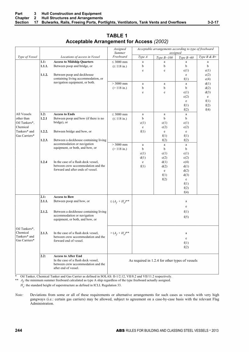
Part 3 Hull Construction and Equipment Chapter 2 Hull Structures and Arrangements Section 17 Bulwarks, Rails, Freeing Ports, Portlights, Ventilators, Tank Vents and Overflows 3-2-17
244 ABS RULES FOR BUILDING AND CLASSING STEEL VESSELS . 2013
TABLE 1 Acceptable Arrangement for Access (2002)
Assigned Summer
Freeboard
Acceptable arrangements according to type of freeboard assigned
Type of Vessel Locations of access in Vessel Type A Type B−100 Type B−60 Type B & B+ 1.1: Access to Midship Quarters ≤ 3000 mm a a a a 1.1.1. Between poop and bridge, or (≤ 118 in.) b b b b e e c(1) c(1) 1.1.2. Between poop and deckhouse
containing living accommodation, or navigation equipment, or both.
e c(2) f(1) c(4) > 3000 mm a a a d(1) (> 118 in.) b b b d(2) e e c(1) d(3) c(2) e e f(1) f(1) f(2) f(2) f(4) All Vessels 1.2: Access to Ends ≤ 3000 mm a a a other than 1.2.1 Between poop and bow (if there is no
bridge), or (≤ 118 in.) b b b
Oil Tankers*, c(1) c(1) c(1) Chemical e c(2) c(2) Tankers* and 1.2.2. Between bridge and bow, or f(1) e e Gas Carriers* f(1) f(1) 1.2.3. Between a deckhouse containing living
accommodation or navigation equipment, or both, and bow, or
f(2) f(2) > 3000 mm a a a (> 118 in.) b b b c(1) c(1) c(1) d(1) c(2) c(2) 1.2.4 In the case of a flush deck vessel,
between crew accommodation and the forward and after ends of vessel.
e d(1) c(4) f(1) d(2) d(1) e d(2) f(1) d(3) f(2) e f(1) f(2) f(4)
Oil Tankers*, Chemical Tankers* and Gas Carriers*
2.1: Access to Bow 2.1.1. Between poop and bow, or ≤ (Af + Hs)** a e 2.1.2. Between a deckhouse containing living
accommodation or navigation equipment, or both, and bow, or
f(1) f(5) 2.1.3. In the case of a flush deck vessel,
between crew accommodation and the forward end of vessel.
> (Af + Hs)** a e f(1) f(2) 2.2: Access to After End In the case of a flush deck vessel,
between crew accommodation and the after end of vessel.
As required in 1.2.4 for other types of vessels
* Oil Tanker, Chemical Tanker and Gas Carrier as defined in SOLAS: II-1/2.12, VII/8.2 and VII/11.2 respectively. ** Af: the minimum summer freeboard calculated as type A ship regardless of the type freeboard actually assigned.
Hs: the standard height of superstructure as defined in ICLL Regulation 33. Note: Deviations from some or all of these requirements or alternative arrangements for such cases as vessels with very high
gangways (i.e.: certain gas carriers) may be allowed, subject to agreement on a case-by-case basis with the relevant Flag Administration.
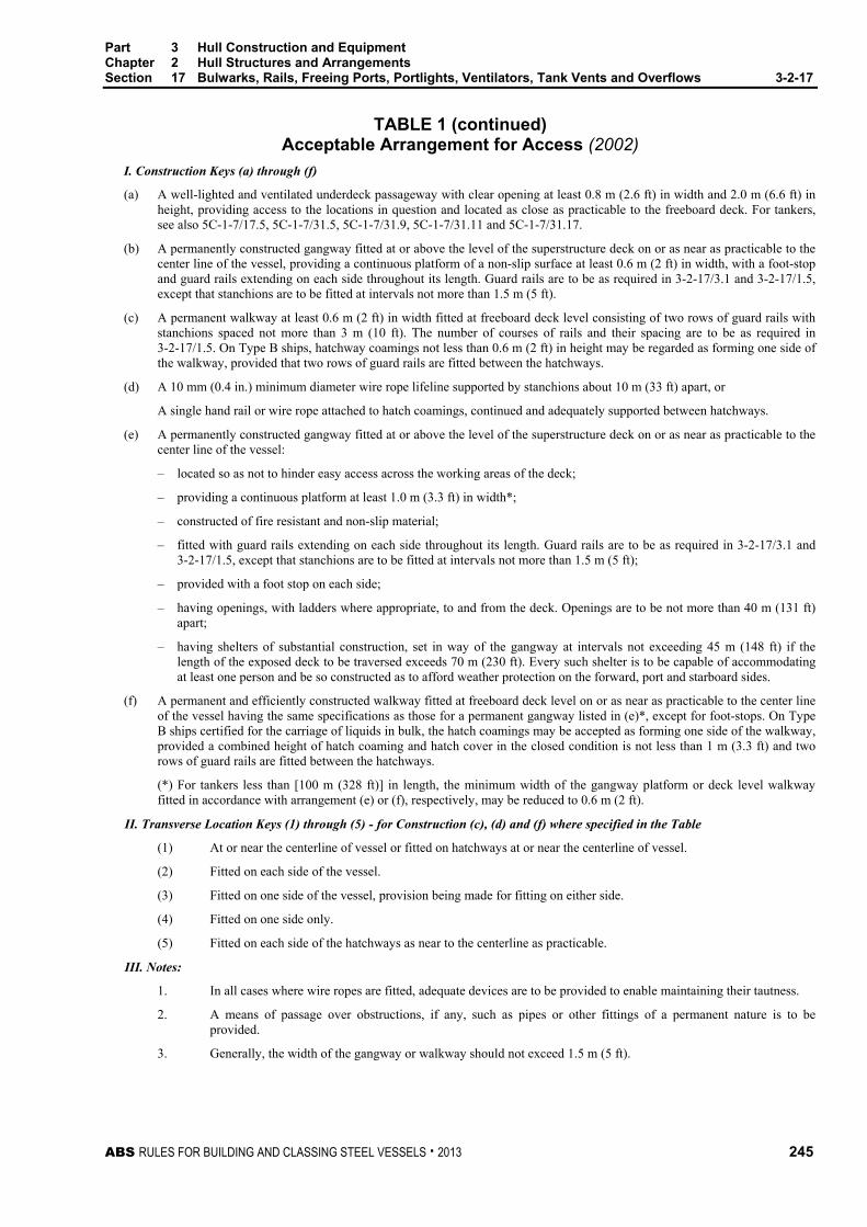
Part 3 Hull Construction and Equipment Chapter 2 Hull Structures and Arrangements Section 17 Bulwarks, Rails, Freeing Ports, Portlights, Ventilators, Tank Vents and Overflows 3-2-17
ABS RULES FOR BUILDING AND CLASSING STEEL VESSELS . 2013 245
TABLE 1 (continued) Acceptable Arrangement for Access (2002)
I. Construction Keys (a) through (f)
(a) A well-lighted and ventilated underdeck passageway with clear opening at least 0.8 m (2.6 ft) in width and 2.0 m (6.6 ft) in height, providing access to the locations in question and located as close as practicable to the freeboard deck. For tankers, see also 5C-1-7/17.5, 5C-1-7/31.5, 5C-1-7/31.9, 5C-1-7/31.11 and 5C-1-7/31.17.
(b) A permanently constructed gangway fitted at or above the level of the superstructure deck on or as near as practicable to the center line of the vessel, providing a continuous platform of a non-slip surface at least 0.6 m (2 ft) in width, with a foot-stop and guard rails extending on each side throughout its length. Guard rails are to be as required in 3-2-17/3.1 and 3-2-17/1.5, except that stanchions are to be fitted at intervals not more than 1.5 m (5 ft).
(c) A permanent walkway at least 0.6 m (2 ft) in width fitted at freeboard deck level consisting of two rows of guard rails with stanchions spaced not more than 3 m (10 ft). The number of courses of rails and their spacing are to be as required in 3-2-17/1.5. On Type B ships, hatchway coamings not less than 0.6 m (2 ft) in height may be regarded as forming one side of the walkway, provided that two rows of guard rails are fitted between the hatchways.
(d) A 10 mm (0.4 in.) minimum diameter wire rope lifeline supported by stanchions about 10 m (33 ft) apart, or
A single hand rail or wire rope attached to hatch coamings, continued and adequately supported between hatchways.
(e) A permanently constructed gangway fitted at or above the level of the superstructure deck on or as near as practicable to the center line of the vessel:
– located so as not to hinder easy access across the working areas of the deck;
– providing a continuous platform at least 1.0 m (3.3 ft) in width*;
– constructed of fire resistant and non-slip material;
– fitted with guard rails extending on each side throughout its length. Guard rails are to be as required in 3-2-17/3.1 and 3-2-17/1.5, except that stanchions are to be fitted at intervals not more than 1.5 m (5 ft);
– provided with a foot stop on each side;
– having openings, with ladders where appropriate, to and from the deck. Openings are to be not more than 40 m (131 ft) apart;
– having shelters of substantial construction, set in way of the gangway at intervals not exceeding 45 m (148 ft) if the length of the exposed deck to be traversed exceeds 70 m (230 ft). Every such shelter is to be capable of accommodating at least one person and be so constructed as to afford weather protection on the forward, port and starboard sides.
(f) A permanent and efficiently constructed walkway fitted at freeboard deck level on or as near as practicable to the center line of the vessel having the same specifications as those for a permanent gangway listed in (e)*, except for foot-stops. On Type B ships certified for the carriage of liquids in bulk, the hatch coamings may be accepted as forming one side of the walkway, provided a combined height of hatch coaming and hatch cover in the closed condition is not less than 1 m (3.3 ft) and two rows of guard rails are fitted between the hatchways.
(*) For tankers less than [100 m (328 ft)] in length, the minimum width of the gangway platform or deck level walkway fitted in accordance with arrangement (e) or (f), respectively, may be reduced to 0.6 m (2 ft).
II. Transverse Location Keys (1) through (5) - for Construction (c), (d) and (f) where specified in the Table
(1) At or near the centerline of vessel or fitted on hatchways at or near the centerline of vessel.
(2) Fitted on each side of the vessel.
(3) Fitted on one side of the vessel, provision being made for fitting on either side.
(4) Fitted on one side only.
(5) Fitted on each side of the hatchways as near to the centerline as practicable.
III. Notes:
1. In all cases where wire ropes are fitted, adequate devices are to be provided to enable maintaining their tautness.
2. A means of passage over obstructions, if any, such as pipes or other fittings of a permanent nature is to be provided.
3. Generally, the width of the gangway or walkway should not exceed 1.5 m (5 ft).
Part 3 Hull Construction and Equipment Chapter 2 Hull Structures and Arrangements Section 17 Bulwarks, Rails, Freeing Ports, Portlights, Ventilators, Tank Vents and Overflows 3-2-17
246 ABS RULES FOR BUILDING AND CLASSING STEEL VESSELS . 2013
5 Freeing Ports
5.1 Basic Area Where bulwarks on the weather portions of freeboard or superstructure decks form wells, ample provision is to be made for rapidly freeing the decks of water and for draining them. Except as provided in 3-2-17/5.3 and 3-2-17/5.5, the minimum freeing-port area A on each side of the vessel for each well on the freeboard deck is to be obtained from the following equations in cases where the sheer in way of the well is standard or greater than standard (Standard sheer as defined in the International Convention on Load Lines, 1966). The minimum area for each well on superstructure decks is to be one-half of the area obtained from the following equation:
Where the length of bulwark in the well is 20 m (66 ft) or less:
A = 0.7 + 0.035 m2 A = 7.6 + 0.115 ft2
Where exceeds 20 m (66 ft):
A = 0.07 m2 A = 0.23 ft2
In no case need be taken as greater than 0.7Lf where Lf is as defined in 3-1-1/3.3. If the bulwark is more than 1.2 m (3.9 ft) in average height, the required area is to be increased by 0.004 m2 per m (0.04 ft2 per ft) of length of well for each 0.1 m (1 ft) difference in height. If the bulwark is less than 0.9 m (3 ft) in average height, the required area may be decreased by 0.004 m2 per m (0.04 ft2 per ft) of length of well for each 0.1 m (1 ft) difference in height.
5.3 Vessels with Less than Standard Sheer In vessels with no sheer, the calculated area is to be increased by 50%. Where the sheer is less than the standard, the percentage is to be obtained by interpolation.
5.5 Trunks Where a vessel is fitted with a trunk, and open rails are not fitted on weather parts of the freeboard deck in way of the trunk for at least half their length, or where continuous or substantially continuous hatchway side coamings are fitted between detached superstructures, the minimum area of the freeing-port openings is to be calculated from the following table.
Breadth of hatchway or trunk in relation to the breadth of vessel
Area of freeing ports in relation to the total area of the bulwarks
40% or less 20% 75% or more 10%
The area of freeing ports at intermediate breadths is to be obtained by linear interpolation.
5.7 Open Superstructures In vessels having superstructures which are open at either or both ends, adequate provision for freeing the space within such superstructures is to be provided, and the arrangements are to be subject to special approval.
5.9 Details of Freeing Ports The lower edges of the freeing ports are to be as near the deck as practicable. Two-thirds of the freeing-port area required is to be provided in the half of the well nearest the lowest point of the sheer curve. All such openings in the bulwarks are to be protected by rails or bars spaced approximately 230 mm (9 in.) apart. If shutters are fitted to freeing ports, ample clearance is to be provided to prevent jamming. Hinges are to have pins or bearings of noncorrodible material and in general are to be located at or near the top of the shutters. If shutters are fitted with securing appliances, these are to be of approved construction.
Part 3 Hull Construction and Equipment Chapter 2 Hull Structures and Arrangements Section 17 Bulwarks, Rails, Freeing Ports, Portlights, Ventilators, Tank Vents and Overflows 3-2-17
ABS RULES FOR BUILDING AND CLASSING STEEL VESSELS . 2013 247
7 Portlights
7.1 Application (1 July 1998) This subsection applies to passenger vessels and cargo vessels. See 5C-7-2/7.13. As such, any reference to bulkhead/freeboard deck means bulkhead deck in the case of passenger vessels and freeboard deck in the case of cargo vessels.
7.3 Location (1 July 1998) No portlight is to be fitted in a position with its sill below a line drawn parallel to the bulkhead/ freeboard deck at side and having its lowest point 2.5% of the breadth of the vessel above the load waterline (or summer timber load waterline, if assigned), or 500 mm (19.5 in.), whichever is the greater distance.
In addition, portlights are not to be fitted in spaces which are used exclusively for the carriage of cargo.
7.5 Construction (1 July 1998) 7.5.1 General
Portlights to spaces below the bulkhead/freeboard deck or to spaces within enclosed superstructures are to be fitted with efficient hinged, inside deadlights arranged so that they can be effectively closed and secured watertight. The portlights, together with their glasses and deadlights, are to comply with a recognized standard. They are to have strong frames (other than cast iron) and opening-type portlights are to have noncorrosive hinge pins.
7.5.2 Non-opening Type Where vessels are subject to damage stability requirements of 3-3-1/3.3, portlights found to be situated below a final damage equilibrium waterline are to be of non-opening type.
7.5.3 Locked Type Portlights where permitted in 3-2-17/7.5.2 to be of opening type are to be of such construction as will prevent unauthorized opening where:
7.5.3(a) the sills of which are below the bulkhead/freeboard deck as permitted in 3-2-17/7.3, or
7.5.3(b) fitted in spaces used alternatively for the carriage of cargo or passengers.
7.5.4 Automatic Ventilating Type Automatic ventilating portlights are not to be fitted in the shell plating below the bulkhead/freeboard deck without special approval.

Part 3 Hull Construction and Equipment Chapter 2 Hull Structures and Arrangements Section 17 Bulwarks, Rails, Freeing Ports, Portlights, Ventilators, Tank Vents and Overflows 3-2-17
248 ABS RULES FOR BUILDING AND CLASSING STEEL VESSELS . 2013
9 Ventilators, Tank Vents and Overflows (2004)
9.1 General (2004) Ventilators are to comply with the requirements of 3-2-17/9.3. Tank vents and overflows are to comply with the requirements in 3-2-17/9.5. In addition, for those located on the fore deck, the requirements given in 3-2-17/9.7 are to be complied with.
9.3 Ventilators (2004)
9.3.1 Construction of Coamings (2002)
Ventilators on exposed freeboard or superstructure decks to spaces below the freeboard deck or decks of enclosed superstructures are to have coamings of steel or other equivalent material. Coaming-plate thickness is not to be less than 7.5 mm (0.30 in.) for ventilators up to 200 mm (8 in.) in diameter, and 10 mm (0.40 in.) for diameters of 457 mm (18 in.) and above; the thicknesses for intermediate diameters may be obtained by interpolation. Coamings are to be effectively and properly secured to properly stiffened deck plating of sufficient thickness. Coamings which are more than 900 mm (35.5 in.) high and which are not supported by adjacent structures are to have additional strength and attachment. Ventilators passing through superstructures, other than enclosed superstructures, are to have substantially constructed coamings of steel at the freeboard deck. Where a fire damper is located within a ventilation coaming, an inspection port or opening at least 150 mm (6 in.) in diameter is to be provided in the coaming to facilitate survey of the damper without disassembling the coaming or the ventilator. The closure provided for the inspection port or opening is to maintain the watertight integrity of the coaming and, if appropriate, the fire integrity of the coaming.
9.3.2 Height of Coamings
Ventilators in Position 1 are to have coamings at least 900 mm (35.5 in.) above the deck. Ventilators in Position 2 are to have coamings at least 760 mm (30 in.) above the deck. (See 3-2-15/3 for definition of Positions 1 and 2.) In exposed positions, the height of coamings may be required to be increased.
9.3.3 Means for Closing Openings
Except as provided below, ventilator openings are to be provided with efficient, permanently attached closing appliances. Ventilators in Position 1, the coamings of which extend to more than 4.5 m (14.8 ft) above the deck, and in Position 2, the coamings of which extend to more than 2.3 m (7.5 ft) above the deck, need not be fitted with closing arrangements unless unusual features of the design make it necessary. See also 4-7-2/1.9.5 and 4-7-2/1.9.6.
9.5 Tank Vents and Overflows (2004) Tank vents and overflows are to be in accordance with the requirements of 4-6-4/9.3 and 4-6-4/9.5 of these Rules. In addition, where applicable, the requirements given below in 3-2-17/9.7 are to be complied with.
9.7 Ventilators, Tank Vents and Overflows on the Fore Deck (2004)
9.7.1 Application
The requirements of this paragraph apply to all ventilators, tank vents and overflows located on the exposed fore deck within the forward 0.25L and where the height of the exposed deck in way of the item is less than 0.1L or 22 meters (72 ft) above the summer load waterline, whichever is the lesser.
9.7.2 Applied Loading to the Air Pipes and Ventilators
9.7.2(a) Pressure. The pressures p, in kN/m2 (tf/m2, Ltf/ft2), acting on air pipes, ventilator pipes and their closing devices, may be calculated from:
p = f V2 Cd Cs Cp kN/m2 (tf/m2, Ltf/ft2)

Part 3 Hull Construction and Equipment Chapter 2 Hull Structures and Arrangements Section 17 Bulwarks, Rails, Freeing Ports, Portlights, Ventilators, Tank Vents and Overflows 3-2-17
ABS RULES FOR BUILDING AND CLASSING STEEL VESSELS . 2013 249
where:
f = 0.5 (0.05, 0.0156)
= density of sea water, 1.025 t/m3 (1.025 t/m3, 0.0286 Lt/ft3)
V = velocity of water over the fore deck, 13.5 m/sec (44.3 ft/sec)
Cd = shape coefficient
= 0.5 for pipes
= 1.3 for pipes or ventilator heads in general
= 0.8 for pipes or ventilator heads of cylindrical form with their axis in the vertical direction
Cs = slamming coefficient, 3.2
Cp = protection coefficient:
= 0.7 for pipes and ventilator heads located immediately behind a breakwater or forecastle
= 1.0 elsewhere, including immediately behind a bulwark
9.7.2(b) Force. Forces acting in the horizontal direction on the pipe and its closing device may be calculated from the above pressure using the largest projected area of each component.
9.7.3 Strength Requirements for Ventilators, Tank Vents and Overflows and their Closing Devices
9.7.3(a) Bending Moment and Stress. Bending moments and stresses in air pipes and ventilator pipes are to be calculated at critical positions: at penetration pieces, at weld or flange connections, at toes of supporting brackets. Bending stresses in the net section are not to exceed 0.8Y, where Y is the specified minimum yield stress or 0.2% proof stress of the steel at room temperature. Irrespective of corrosion protection, a corrosion addition to the net section of 2.0 mm (0.08 in.) is then to be applied.
9.7.3(b) Tank Vents and Overflows
i) For standard tank vents and overflows of 760 mm (30 in.) height closed by heads of not more than the tabulated projected area, pipe thicknesses and bracket heights are specified in 3-2-17/Table 2. Where brackets are required, three or more radial brackets are to be fitted.
ii) Brackets are to be of gross thickness of 8 mm (0.32 in.) or more, of minimum length of 100 mm (4.0 in.), and height according to 3-2-17/Table 2, but need not extend over the joint flange for the head. Bracket toes at the deck are to be suitably supported.
iii) For other configurations, loads according to 3-2-17/9.7.2 are to be applied, and means of support determined in order to comply with the requirements above. Brackets, where fitted, are to be of suitable thickness and length according to their height.
iv) Final (gross) pipe thickness is not to be taken less than as indicated in 4-6-4/9.3.2 and 4-6-4/9.5.6.
v) The minimum internal diameter of the air pipe or overflow is not to be less than 65 mm.
9.7.3(c) Ventilators
i) For standard ventilators of 900 mm (35.4 in.) height closed by heads of not more than the tabulated projected area, pipe thicknesses and bracket heights are specified in 3-2-17/Table 3. Brackets, where required, are to be as specified in 3-2-17/9.7.3(b)iii).
ii) For ventilators of height greater than 900 mm (35.4 in.), brackets or alternative means of support are to be provided. Coamings are not to be taken less than as indicated in 3-2-17/9.3 nor in 3-2-17/Table 2.
9.7.3(d) Components and Connections. All component parts and connections of the tank vents and overflows or ventilators are to be capable of withstanding the loads defined in 3-2-17/9.7.2.
9.7.3(e) Rotary Heads. Rotating type mushroom ventilator heads are not to be used for applications in this location

Part 3 Hull Construction and Equipment Chapter 2 Hull Structures and Arrangements Section 17 Bulwarks, Rails, Freeing Ports, Portlights, Ventilators, Tank Vents and Overflows 3-2-17
250 ABS RULES FOR BUILDING AND CLASSING STEEL VESSELS . 2013
TABLE 2 760 mm (30 in.) High Tank Vents and Overflows
Thickness and Bracket Standards (2004)
Nominal Pipe Size Minimum Fitted Gross Thickness
Maximum Projected Area of Head
Height (1) of Brackets A B
mm in. mm in. cm2 in2 mm in. 65 21/2 6.0 --- --- --- 480 18.9 80 3 6.3 0.25 --- --- 460 18.1
100 4 7.0 0.28 --- --- 380 15.0 125 5 7.8 0.31 --- --- 300 11.8 150 6 8.5 0.33 --- --- 300 11.8 175 7 8.5 0.33 --- --- 300 11.8 200 8 8.5 (2) 0.33 (2) 1900 295 300 11.8 250 10 8.5 (2) 0.33 (2) 2500 388 300 (2) 11.8 (2)
300 12 8.5 (2) 0.33 (2) 3200 496 300 (2) 11.8 (2) 350 14 8.5 (2) 0.33 (2) 3800 589 300 (2) 11.8 (2) 400 16 8.5 (2) 0.33 (2) 4500 698 300 (2) 11.8 (2)
Notes: 1 Brackets [see 3-2-17/9.7.3(b)] need not extend over the joint flange for the head.
2 Brackets are required where the as fitted (gross) thickness is less than 10.5 mm (0.41 in.) or where the tabulated projected head area is exceeded.
Note: For other air pipe heights, the relevant requirements of 3-2-17/9.7.3 are to be applied.
TABLE 3 900 mm (35.4 in.) High Ventilator
Thickness and Bracket Standards (2004) Nominal Pipe Size Minimum Fitted
Gross Thickness Maximum Projected
Area of Head Height (1)
of Brackets A B mm in. mm in. cm2 in2 mm in. 80 3 6.3 0.25 - - 460 18.1
100 4 7.0 0.28 - - 380 15.0 150 6 8.5 0.33 - - 300 11.8 200 8 8.5 0.33 550 85 - - 250 10 8.5 0.33 880 136 - -
300 12 8.5 0.33 1200 186 - - 350 14 8.5 0.33 2000 310 - - 400 16 8.5 0.33 2700 419 - - 450 18 8.5 0.33 3300 511 - - 500 20 8.5 0.33 4000 620 - -
Note: For other ventilator heights, the relevant requirements of 3-2-17/9.7.3 are to be applied.

ABS RULES FOR BUILDING AND CLASSING STEEL VESSELS . 2013 251
P A R T S e c t i o n 1 8 : C e i l i n g , S p a r r i n g a n d P r o t e c t i o n o f S t e e l
3 C H A P T E R 2 Hull Structures and Arrangements
S E C T I O N 18 Ceiling, Sparring and Protection of Steel
1 Close Ceiling (1997) Ceiling, where fitted, is to be laid either directly on a tightening and preserving compound or on battens. On vessels with sloping margin plate, the ceiling from the margin plate to the upper part of the bilge is to be arranged so as to be readily removable for inspection. Except for holds intended exclusively for the carriage of containers on the inner bottom, ceiling is to be fitted under all hatchways unless the inner bottom plating is increased by at least 2 mm (0.08 in.).
3 Sparring Sparring is to be fitted to the sides above the bilge ceiling, if any, in all cargo spaces where it is intended to carry general cargo. The sparring is not to be less than 40 mm (1.625 in.) thick, finished, nor is it to provide less protection to the framing than is obtained from battens at least 140 mm (5.5 in.) wide, finished, and spaced 380 mm (15 in.) center to center. Sparring is to be bolted, fitted in cleats, or in portable frames for convenience in removal. Sparring may be omitted in vessels engaged in the carriage of coal, bulk cargoes, containers and similar cargoes. In such cases, the notation NS will be entered in the Record, indicating no sparring.
5 Corrosion Protection of Steel (1 July 2012)
5.1 All Spaces (2012) Unless otherwise approved, all steel work is to be suitably protected by an efficient corrosion prevention system, such as hard protective coatings or equivalent.
5.3 Cargo Holds on Bulk Carriers (including Combination Carriers) (1998) All internal and external surfaces of hatch coamings and hatch covers, and all internal surfaces of cargo holds, excluding the flat tank top areas and the hopper tank sloping plating up to approximately 300 mm (12 in.) below the side shell frame end brackets, are to have an epoxy or equivalent coating applied in accordance with the manufacturer’s recommendations. The internal surface of the cargo hold includes those surfaces of stiffening members of the top wing tank bottom, where fitted on the hold side, and deck plating and associated beams, girders, etc. facing holds such as those between the main hatchways. See 3-2-18/Figure 1.
In the selection of coatings, due consideration is to be given by the Owner to the intended cargoes and conditions expected in service.

Part 3 Hull Construction and Equipment Chapter 2 Hull Structures and Arrangements Section 18 Ceiling, Sparring and Protection of Steel 3-2-18
252 ABS RULES FOR BUILDING AND CLASSING STEEL VESSELS . 2013
FIGURE 1 Extent of Coatings (1998)
Minimum300 mm(12 in)
Coating
b) HOLD, HATCH COAMINGSAND HATCH COVER
Coating
a) TRANSVERSEBULKHEAD
5.5 Fuel Oil Tanks (2012) Corrosion protective coating is not required for internal surfaces of spaces intended for the carriage of fuel oil.
ABS RULES FOR BUILDING AND CLASSING STEEL VESSELS . 2013 253
P A R T S e c t i o n 1 9 : W e l d D e s i g n
3 C H A P T E R 2 Hull Structures and Arrangements
S E C T I O N 19 Weld Design
1 Fillet Welds
1.1 General 1.1.1 Plans and Specifications
The actual sizes of fillet welds are to be indicated on detail drawings or on a separate welding schedule and submitted for approval in each individual case. In determining weld sizes based on the equations in this Section, the nearest 1/2 mm (1/32 in.) may be used.
1.1.2 Workmanship Completed welds are to be to the satisfaction of the attending Surveyor. The gaps between the faying surfaces of members being joined should be kept to a minimum. Where the opening between members being joined exceeds 2.0 mm (0.08 in.) and is not greater than 5 mm (3/16 in.), the weld leg size is to be increased by the amount of the opening in excess of 2.0 mm (0.08 in.). Where the opening between members is greater than 5 mm (3/16 in.), corrective procedures are to be specially approved by the Surveyor.
1.1.3 Special Precautions Special precautions, such as the use of preheat or low-hydrogen electrodes or low-hydrogen welding processes, may be required where small fillets are used to attach heavy plates or sections. When heavy sections are attached to relatively light plating, the weld size may be required to be modified.
3 Tee Connections
3.1 Size of Fillet Welds Tee connections are generally to be formed by continuous or intermittent fillet welds on each side, as required by 3-2-19/Table 1. The leg size, w, of fillet welds (see figure in 3-2-19/Table 1) is obtained from the following equations:
w = tp × C ×
s + 2.0 mm
or
w = tp × C ×
s + 0.08 in.
wmin = 0.3tp or 4.5 mm (0.18 in.) [4.0 mm (0.16 in.) where 3-2-19/9 is applicable], whichever is greater.
where
= the actual length of weld fillet, clear of crater, in mm (in.)
s = the distance between successive weld fillets, from center to center, in mm (in.)

Part 3 Hull Construction and Equipment Chapter 2 Hull Structures and Arrangements Section 19 Weld Design 3-2-19
254 ABS RULES FOR BUILDING AND CLASSING STEEL VESSELS . 2013
s/ = 1.0 for continuous fillet welding
tp = thickness of the thinner of the two members being joined, in mm (in.)
C = weld factors given in 3-2-19/Table 1
In selecting the leg size and spacing of matched fillet welds, the leg size for the intermittent welds is to be taken as not greater than the designed leg size w or 0.7tp + 2.00 mm (0.7tp + 0.08 in.), whichever is less.
The throat size, t, is to be not less than 0.70 w.
For the weld size for tp 6.5 mm (0.25 in.) or less, see 3-2-19/3.11.
3.3 Length and Arrangement of Fillet Where an intermittent weld is permitted by 3-2-19/Table 1, the length of each fillet weld is to be not less than 75 mm (3 in.) for tp of 7 mm (0.28 in.) or more, nor less than 65 mm (2.5 in.) for lesser tp. The unwelded length on one side is to be not more than 32tp.
3.5 Intermittent Welding at Intersection Where beams, stiffeners, frames, etc., are intermittently welded and pass through slotted girders, shelves or stringers, there is to be a pair of matched intermittent welds on each side of each such intersection, and the beams, stiffeners and frames are to be efficiently attached to the girders, shelves and stringers.
3.7 Welding of Longitudinal to Plating Welding of longitudinals to plating is to have double continuous welds at the ends and in way of transverses equal in length to depth of the longitudinal. For deck longitudinals only, a matched pair of welds is required at the transverses.
3.9 Stiffeners and Webs to Hatch Covers Unbracketed stiffeners and webs of hatch covers are to be welded continuously to the plating and to the face plate for a length at ends equal to the end depth of the member.
3.11 Thin Plating For plating of 6.5 mm (0.25 in.) or less, the requirements of 3-2-19/3.1 may be modified as follows:
w = tpC
s + 2.0
−
s25.1 mm
w = tp C
s + 0.08
−
s25.1 in.
wmin = 3.5 mm (0.14 in.)
The use of the above equations for plating in excess of 6.5 mm (0.25 in.) may be specially considered depending upon the location and the quality control procedure.

Part 3 Hull Construction and Equipment Chapter 2 Hull Structures and Arrangements Section 19 Weld Design 3-2-19
ABS RULES FOR BUILDING AND CLASSING STEEL VESSELS . 2013 255
TABLE 1 Weld Factors
Staggered Chained
S
w
wt
SS
w = leg size in mm (in.) t = throat size in mm (in.)
I. Periphery Connections Factor C C = Continuous DC = Double Continuous
A. Tight Joints 1. Strength deck to sheer strake (See 3-2-19/15) 0.42 DC 2. Main longitudinal bulkhead to deck, bottom or inner bottom (See 3-2-19/15) 0.42 DC 3. All other tight joints except X.B. (See 3-2-9/7.5) a. watertight bulkhead, tp ≤ 12.5 mm (0.50 in.) where one side intermittent and the
other side continuous 0.12 & 0.58 C
where double continuous 0.35 DC b. all other joints 0.35 DC B. Non-tight Joints 1. Platform decks 0.28 DC 2. Swash bulkheads in deep tanks 0.20 3. Non-tight bulkheads other than B2 0.15
II. Bottom Floors 1. To Shell (1993) a. in aft peak below waterline 0.25 DC b. in machinery space 0.20 DC c. flat of bottom forward 0.15 d. in aft peak above waterline and in forward peak 0.15 e. elsewhere (See note 5) 0.12 2. To Inner Bottom a. in machinery space 0.20 DC b. at forward end (fore end strengthening) 0.15 c. elsewhere (See note 5) 0.12 3. To Center or Side Girder a. in way of engine 0.30 DC b. with longitudinal framing 0.30 DC c. with transverse framing 0.17 4. To Margin Plate, Side Shell, Longitudinal Bulkhead or Bilge 0.35 DC 5. Open Floor Bracket a. to center girder 0.15 b. to margin plate 0.30 DC

Part 3 Hull Construction and Equipment Chapter 2 Hull Structures and Arrangements Section 19 Weld Design 3-2-19
256 ABS RULES FOR BUILDING AND CLASSING STEEL VESSELS . 2013
TABLE 1 (continued) Weld Factors
III. Bottom Girder 1. Center Girder a. to inner bottom in way of engine 0.30 DC b. to inner bottom clear of engine, non-tight 0.23 c. to shell, non-tight 0.25 DC 2. Side Girder a. to floors in way of transverse bulkheads 0.35 DC b. to shell—flat of bottom forward 0.23 —elsewhere 0.15 c. to inner bottom—in way of engine 0.23 —elsewhere 0.15
IV. Web Frames, Stringers, Deck Girders and Deck Transverses 1. To Plating a. in tanks 0.20 b. elsewhere 0.15 2. To Face Plates a. face area ≤ 64.5 cm2 (10 in2) 0.12 b. face area > 64.5 cm2 (10 in2) 0.15 3. End Attachment a. unbracketed (see note 1) 0.55 DC b. bracketed 0.40 DC
V. Frames, Beams and Stiffeners 1. To Shell (1993) a. in aft peak below waterline 0.25 DC b. flat of bottom forward 0.25 DC c. 0.125L forward 0.15 d. in aft peak above waterline and in forward peak 0.15 2. Slab longitudinals (1998) (see note 2) 3. To plating elsewhere 0.12 4. End attachment a. unbracketed (see note 1) 0.45 DC b. bracketed 0.35 DC
VI. Hatch Covers 1. Oiltight Joints 0.40 DC 2. Watertight Joints Outside 0.40 C Inside 0.15 3. Stiffeners and Webs to Plating and to Face Plate (see note 4) 0.12 4. Stiffeners and Web to Side Plating or other stiffeners —unbracketed (see note 1) 0.45 DC —bracketed 0.35 DC
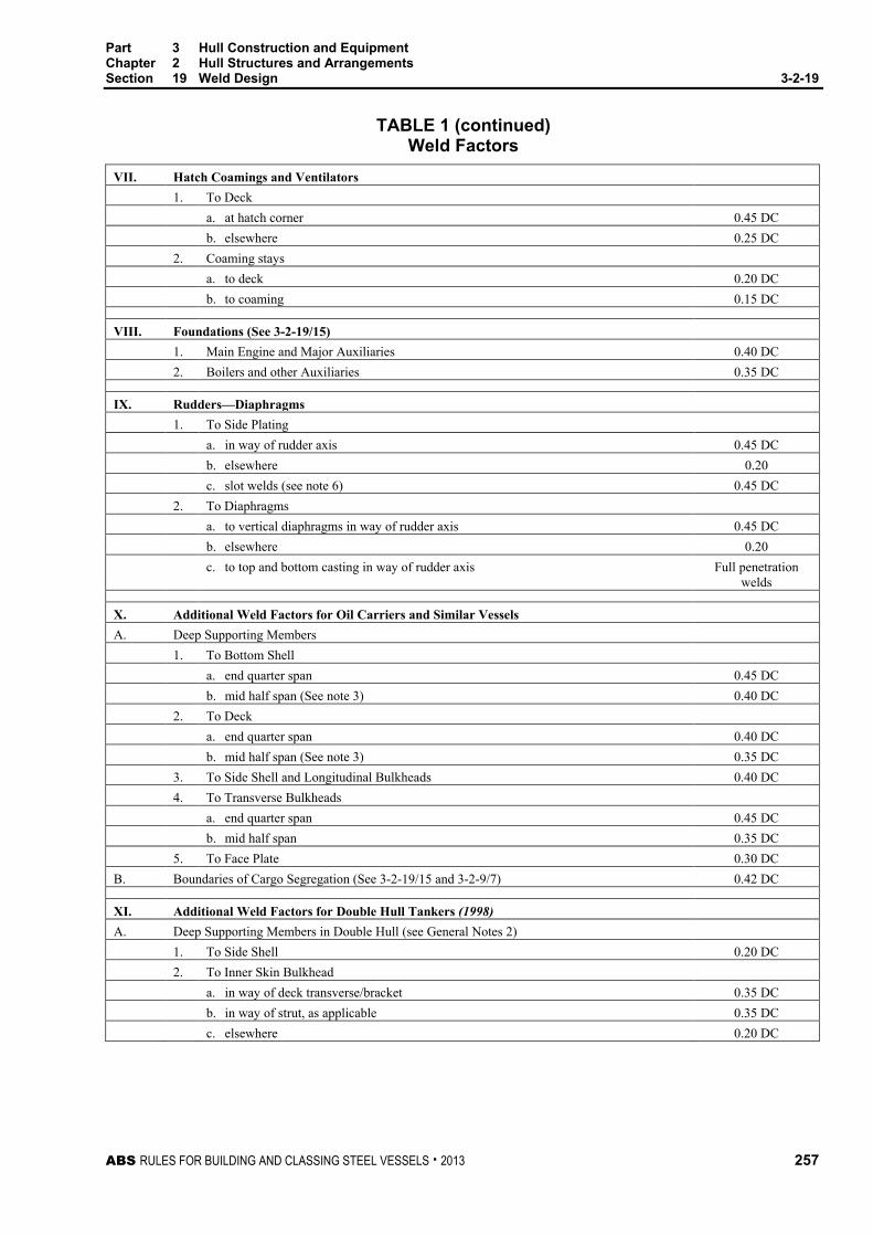
Part 3 Hull Construction and Equipment Chapter 2 Hull Structures and Arrangements Section 19 Weld Design 3-2-19
ABS RULES FOR BUILDING AND CLASSING STEEL VESSELS . 2013 257
TABLE 1 (continued) Weld Factors
VII. Hatch Coamings and Ventilators 1. To Deck a. at hatch corner 0.45 DC b. elsewhere 0.25 DC 2. Coaming stays a. to deck 0.20 DC b. to coaming 0.15 DC
VIII. Foundations (See 3-2-19/15) 1. Main Engine and Major Auxiliaries 0.40 DC 2. Boilers and other Auxiliaries 0.35 DC
IX. Rudders—Diaphragms 1. To Side Plating a. in way of rudder axis 0.45 DC b. elsewhere 0.20 c. slot welds (see note 6) 0.45 DC 2. To Diaphragms a. to vertical diaphragms in way of rudder axis 0.45 DC b. elsewhere 0.20 c. to top and bottom casting in way of rudder axis Full penetration
welds
X. Additional Weld Factors for Oil Carriers and Similar Vessels A. Deep Supporting Members 1. To Bottom Shell a. end quarter span 0.45 DC b. mid half span (See note 3) 0.40 DC 2. To Deck a. end quarter span 0.40 DC b. mid half span (See note 3) 0.35 DC 3. To Side Shell and Longitudinal Bulkheads 0.40 DC 4. To Transverse Bulkheads a. end quarter span 0.45 DC b. mid half span 0.35 DC 5. To Face Plate 0.30 DC B. Boundaries of Cargo Segregation (See 3-2-19/15 and 3-2-9/7) 0.42 DC
XI. Additional Weld Factors for Double Hull Tankers (1998) A. Deep Supporting Members in Double Hull (see General Notes 2) 1. To Side Shell 0.20 DC 2. To Inner Skin Bulkhead a. in way of deck transverse/bracket 0.35 DC b. in way of strut, as applicable 0.35 DC c. elsewhere 0.20 DC

Part 3 Hull Construction and Equipment Chapter 2 Hull Structures and Arrangements Section 19 Weld Design 3-2-19
258 ABS RULES FOR BUILDING AND CLASSING STEEL VESSELS . 2013
TABLE 1 (continued) Weld Factors
XI. Additional Weld Factors for Double Hull Tankers (Continued) (1998) 3. To Inner Bottom (floor) a. in way of longitudinal bulkhead web/bracket 0.45 DC b. elsewhere 0.12 DC 4. To bottom side girder in way of bilge 0.35 DC 5. To horizontal shelf plate in way of bilge 0.35 DC
XII. Additional Weld Factors for Single Side Skin Bulk Carriers (1998) Factor C A. Transverse Hold Frames (see notes 1 and 7) 1. To Side Shell a. End Quarter Span (0.63 − Cp /tp )DC b. Remainder (0.57 − Cp /tp )DC 2. End Attachment (to sloping wing tank plating) a. bracketed (0.63 − Cp /tp )DC Cp = 2.00 (0.08) mm (in)
,
Notes 1 The weld size is to be determined from the thickness of the member being attached.
2 (1998) Slab longitudinals within Ds/4 from strength deck – For these slab longitudinals, the leg size w and wmin in 3-2-19/3.1 may both be taken as 0.23tp + 1.0 mm (0.23tp + 0.04 in.) with a minimum of 4.5 mm (0.18 in.), but need not be greater than 8 mm. Where the slab longitudinal is located more than Ds/4 from the strength deck, special consideration will be given to the weld size.
3 This may be applied only where the shearing forces over the mid-half span are no greater than one-half the maximum shearing-force on the member and where the web is of the same depth, clear of end brackets and of the same thickness throughout the length of the member. The weld size is to be determined from the thickness of member being attached.
4 Unbracketed stiffeners and webs of hatch covers are to be welded continuously to the plating and to the face plate for a length at ends equal to the end depth of the member.
5 With longitudinal framing, the weld size is to be increased to give an equivalent weld area to that obtained without cut-outs for longitudinals.
6 (1995) The weld size is to be determined from the thickness of the side plating.
7 (1998) Where the hull form is such that an effective fillet weld cannot be produced, edge preparation of the frame web and bracket may be required to provide the same efficiency of the connection.
General Notes 1 For oil carriers and similar vessels, the leg size in cargo tanks and in ballast tanks in the cargo area is not to be less
than 6 mm (0.25 in.), except where approval has been given in accordance with 3-2-19/9
2 (1998) The weld size is to be increased for high stress areas which are to be confirmed by “Calculation of Structural Responses,” as specified in 5C-1-5/9.

Part 3 Hull Construction and Equipment Chapter 2 Hull Structures and Arrangements Section 19 Weld Design 3-2-19
ABS RULES FOR BUILDING AND CLASSING STEEL VESSELS . 2013 259
5 Tee-Type End Connections Tee-type end connections where fillet welds are used are to have continuous welds on each side. In general, the leg sizes of the welds are to be in accordance with 3-2-19/Table 1 for unbracketed end attachment, but in special cases where heavy members are attached to relatively light plating, the sizes may be modified. Where only the webs of girders, beams and stiffeners are required to be attached to plating, it is recommended that the unattached face plate or flanges be cut back.
7 Ends of Unbracketed Stiffeners Unbracketed stiffeners of shell, watertight and oiltight bulkheads and house fronts are to have double continuous welds for one-tenth of their length at each end.
Unbracketed stiffeners of non-tight structural bulkheads, deckhouse sides and after ends are to have a pair of matched intermittent welds at each end.
9 Reduced Weld Size
9.1 General Reduction in fillet weld sizes, except for slab longitudinals of thickness greater than 25 mm (1.0 in.), may be specially approved by the Surveyor in accordance with either 3-2-19/9.3 or 3-2-19/9.5, provided that the requirements of 3-2-19/3 are satisfied.
9.3 Controlled Gaps Where quality control facilitates working to a gap between members being attached of 1 mm (0.04 in.) or less, a reduction in fillet weld leg size w of 0.5 mm (0.02 in.) may be permitted.
9.5 Deep Penetration Welds Where automatic double continuous fillet welding is used and quality control facilitates working to a gap between members being attached of 1 mm (0.04 in.) or less, a reduction in fillet weld leg size of 1.5 mm (0.06 in.) may be permitted, provided that the penetration at the root is at least 1.5 mm (0.06 in.) into the members being attached.
11 Lapped Joints
11.1 General Lapped joints are generally to have overlaps of not less width than twice the thinner plate thickness plus 25 mm (1.0 in.).
11.3 Overlapped End Connections Overlapped end connections of longitudinal strength members within the midship 0.4L are to have continuous fillet welds on both edges each equal in size w to the thickness of the thinner of the two plates joined. All other overlapped end connections are to have continuous welds on each edge of size w such that the sum of the two is not less than 1.5 times the thickness of the thinner plate.
11.5 Overlapped Seams Overlapped seams are to have continuous welds on both edges of the sizes required by 3-2-19/Table 1 for the boundaries of deep tank or watertight bulkheads, except that for seams of plates 12.5 mm (1/2 in.) or less clear of tanks one edge may have intermittent welds in accordance with 3-2-19/Table 1 for watertight bulkhead boundaries.

Part 3 Hull Construction and Equipment Chapter 2 Hull Structures and Arrangements Section 19 Weld Design 3-2-19
260 ABS RULES FOR BUILDING AND CLASSING STEEL VESSELS . 2013
13 Plug Welds or Slot Welds Plug welds or slot welds may be specially approved for particular applications. Where used in the body of doublers and similar locations, such welds may be spaced about 305 mm (12 in.) between centers in both directions.
15 Full or Partial Penetration Corner or Tee Joints (1994) A full or partial penetration weld may be required for highly stressed (75% or more of the yield) or critical (e.g., oil/water boundary) joints.
Measures taken to achieve full or partial penetration corner or tee joints, where specified, are to be to the satisfaction of the attending Surveyor. The designer is to give consideration to minimize the possibility of lamellar tearing in such joints.
17 Alternatives The foregoing are considered minimum requirements for electric-arc welding in hull construction, but alternative methods, arrangements and details will be considered for approval. See 2-4-3/5. Fillet weld sizes may be determined from structural analyses based on sound engineering principles, provided that they meet the overall strength standards of the Rules.

ABS RULES FOR BUILDING AND CLASSING STEEL VESSELS . 2013 261
P A R T C h a p t e r 3 : S u b d i v i s i o n a n d S t a b i l i t y
3 C H A P T E R 3 Subdivision and Stability
CONTENTS SECTION 1 General Requirements ....................................................................... 263
1 General ........................................................................................... 263 3 Criteria ............................................................................................. 263
3.1 Intact Stability .............................................................................. 263 3.3 Subdivision and Damage Stability ............................................... 263
5 Review Procedures ......................................................................... 264 5.1 Administration Review ................................................................. 264 5.3 ABS Review ................................................................................ 264
7 Damage Control Plan for Dry Cargo Vessels ................................. 264 9 Onboard Computers for Stability Calculations ................................ 264
APPENDIX 1 Intact Stability of Tankers During Liquid Transfer Operations ...... 265
1 General ........................................................................................... 265 1.1 Note ............................................................................................. 265 1.3 Operations to be Addressed ........................................................ 265
APPENDIX 2 Subdivision and Damage Stability Requirements for Bulk
Carriers ............................................................................................... 268 1 General ........................................................................................... 268
1.1 Note ............................................................................................. 268 1.3 Applicability ................................................................................. 268
3 Damage Stability Criteria ................................................................ 268 5 Bulk Carriers with a Reduced Freeboard ........................................ 268
APPENDIX 3 Onboard Computers for Stability Calculations ............................... 269
1 General ........................................................................................... 269 1.1 Scope .......................................................................................... 269 1.3 Design ......................................................................................... 269
3 Calculation Systems ....................................................................... 269 5 Types of Stability Software ............................................................. 270 7 Functional Requirements ................................................................ 270
7.1 Calculation Program .................................................................... 270 7.3 Direct Damage Stability Calculations .......................................... 270 7.5 Warning ....................................................................................... 270 7.7 Data Printout ............................................................................... 270 7.9 Date and Time ............................................................................. 270 7.11 Information of Program ................................................................ 270 7.13 Units ............................................................................................ 270

262 ABS RULES FOR BUILDING AND CLASSING STEEL VESSELS . 2013
9 Acceptable Tolerances ................................................................... 271 9.1 Calculation Program of the Approved Stability Information .......... 271 9.3 Independent Program for Assessment of Stability ....................... 271
11 Approval Procedure ........................................................................ 272 11.1 Conditions of Approval of the Onboard Software for Stability
Calculations ................................................................................. 272 11.3 General Approval (optional) ......................................................... 273 11.5 Specific Approval ......................................................................... 273
13 Operation Manual ........................................................................... 274 15 Installation Testing .......................................................................... 274 17 Periodical Testing ........................................................................... 275 19 Other Requirements ........................................................................ 275 TABLE 1 Acceptable Tolerances ......................................................... 272

ABS RULES FOR BUILDING AND CLASSING STEEL VESSELS . 2013 263
P A R T S e c t i o n 1 : G e n e r a l R e q u i r e m e n t s
3 C H A P T E R 3 Subdivision and Stability
S E C T I O N 1 General Requirements
1 General Vessels of the following categories are to have subdivision and stability in accordance with the criteria as shown.
Attained subdivision index “A” calculated by ABS in accordance with Regulation II-1/7 of SOLAS 1974 as amended (see 3-3-1/3.3 for cargo vessels) will be published in the Record.
3 Criteria
3.1 Intact Stability (2002) Vessels of applicable size, type and service are to have intact stability guidance as required by Regulation 10 of the International Convention on Load Lines. The following criteria may be used for the purpose of classification:
Cargo vessels of all sizes with or without deck cargo: Part A, Chapters 2 and 3.3 of IMO Code on Intact Stability
Offshore supply vessels of all sizes: Part A Chapter 2 and Part B Chapter 2.4 of IMO Code on Intact Stability
Tankers of applicable size, type and service for which the building contract is placed on or after 1 February 1999 or, in the absence of a building contract, the keels of which are laid or which are in a similar stage of construction on or after 1 August 1999 are to have intact stability as required by Regulation 27 in Annex I of the International Convention for Prevention of Pollution from Ships, 1973/1978. Tankers for which that Regulation is not applicable are to meet the requirements in Appendix 3-3-A1, “Intact Stability of Tankers During Liquid Transfer Operations.”
3.3 Subdivision and Damage Stability Vessels of applicable size, type and service are to have subdivision and damage stability as required by the International Convention for the Safety of Life as Sea, 1974, as amended, as follows:
Passenger vessel — Regulation II-1/4 through 8-1 (ABS Rules Section 5C-7-3)
Cargo vessel — Regulation II-1/4 through 7-3
Gas carrier — IGC Code (ABS Rules Section 5C-8-2)
Chemical carrier — IBC Code (ABS Rules Section 5C-9-2)
Bulk carriers for which the request for class for new construction is received on or after 1 July 1998 are to meet the requirements in Appendix 3-3-A2, “Subdivision and Damage Stability Requirements for Bulk Carriers”.

Part 3 Hull Construction and Equipment Chapter 3 Subdivision and Stability Section 1 General Requirements 3-3-1
264 ABS RULES FOR BUILDING AND CLASSING STEEL VESSELS . 2013
5 Review Procedures
5.1 Administration Review (1 February 1999) When the vessel is issued an International Load Line Certificate, Passenger Ship Safety Certificate, Cargo Ship Safety Construction Certificate, International Certificate for Fitness for the Carriage of Liquefied Gas in Bulk, International Certificate for Fitness for the Carriage of Dangerous Chemicals in Bulk or International Oil Pollution Prevention Certificate by the flag Administration or its agent other than ABS, such Certificate will be accepted as evidence that the vessel has subdivision and stability in accordance with the criteria in the respective Convention.
Where the Administration undertakes the review of subdivision and stability and ABS is issuing the above certificate, the acceptance of subdivision and stability by the Administration will be required before the certificate is issued.
5.3 ABS Review In all other cases, the information and calculations for subdivision and stability are to be submitted to ABS for review. Where the intact stability criteria are not applicable to a particular vessel, the review will be in accordance with other recognized criteria acceptable to ABS.
7 Damage Control Plan for Dry Cargo Vessels A plan showing clearly for each deck and hold and boundaries of the watertight compartments, the openings therein with the means of closure and position of any controls thereof, and the arrangements for the correction of any list due to flooding, is to be permanently exhibited or readily available on the navigation bridge. In addition, booklets containing the aforementioned information are to be made available to the officers of the vessel.
9 Onboard Computers for Stability Calculations (1 July 2007) The use of onboard computers for stability calculations is not a requirement of class. However, if stability software is installed onboard vessels contracted on or after 1 July 2005, it should cover all stability requirements applicable to the vessel and is to be approved by ABS for compliance with the requirements of Appendix 3-3-A3, “Onboard Computers for Stability Calculations”.

ABS RULES FOR BUILDING AND CLASSING STEEL VESSELS . 2013 265
P A R T Appendix 1: Intact Stability of Tankers During Liquid Transfer Operations
3 C H A P T E R 3 Subdivision and Stability
A P P E N D I X 1 Intact Stability of Tankers During Liquid Transfer Operations
1 General
1.1 Note The following requirements as specified in 3-3-1/3.1 for tankers (i.e., vessels designed to carry liquid in bulk) are developed from MSC/Circ. 706 (MEPC/Circ. 304), which contains recommendations for existing oil tankers. The phenomenon of lolling is considered to be a safety issue for double hull tankers, as well as for other tankers having exceptionally wide cargo tanks (i.e., having cargo tank breadths greater than 60% of the vessel’s maximum beam), which should be solved for every vulnerable tanker. The solution should not be limited only to tankers subject to MARPOL.
1.3 Operations to be Addressed (1 February 1999) The Appendix applies to any tanker that is not subject to MARPOL Convention Annex I Regulation 27. Alternatively, such tankers may comply with MARPOL Convention Annex I Regulation 27.
3 (1999) Every tanker is to comply with the intact stability criteria specified in 3-3-A1/3.1 and 3-3-A1/3.3 for any operating draught reflecting actual, partial or full load conditions, including the intermediate stages of liquid transfer operations.
Liquid transfer operations include cargo loading and unloading, ballasting and deballasting, ballast water exchange and tank cleaning operations.
3.1 In port, the initial metacentric height GMo is not to be less than 0.15 m. Positive intact stability is to extend from the initial equilibrium position at which GMo is calculated over a range of at least 20 degrees to port and to starboard.
3.3 At sea, the intact stability criteria contained in Part A paragraphs 2.2.1 to 2.2.4 of the IMO Code on Intact Stability, are applicable, or the criteria contained in the national requirements of the flag administration if the national stability requirements provide at least an equivalent degree of safety.
5 (1999) For all loading conditions in port and at sea, including intermediate stages of liquid transfer operations, the initial metacentric height and the righting lever curve are to be corrected for the effect of free surfaces of liquids in tanks. Reference may be made to the Unified Interpretation LL61 Method of Correction for the Effect of Free Surface of Liquids in Tanks, set out by the International Association of Classification Societies.

Part 3 Hull Construction and Equipment Chapter 3 Subdivision and Stability Appendix 1 Intact Stability of Tankers During Liquid Transfer Operations 3-3-A1
266 ABS RULES FOR BUILDING AND CLASSING STEEL VESSELS . 2013
7 The intact stability criteria specified in 3-3-A1/3 preferably is to be met by design of the vessel, i.e., the design should allow for maximum free surface effects in all cargo, ballast and consumables tanks during liquid transfer operations.
9 If the intact stability criteria specified in 3-3-A1/3 are not met through design of the vessel alone, the Master is to be provided with clear instructions covering the operational restrictions and methods necessary to ensure compliance with these criteria during liquid transfer operations. These instructions should be simple and concise, and:
9.1 In a language understood by the officer-in-charge of transfer operations;
9.3 Require no more than minimal mathematical calculations by the officer-in-charge;
9.5 Indicate the maximum number of cargo and ballast tanks which may be slack under any possible condition of liquid transfer;
9.7 Provide pre-planned sequences of cargo/ballast transfer operations, which indicate the cargo and ballast tanks which may be slack to satisfy the stability criteria under any specific condition of liquid transfer, including possible range of cargo densities. The slack tanks may vary during stages of the transfer operations and be any combination which satisfies the stability criteria;
9.9 Provide instructions for pre-planning other sequences of cargo/ballast transfer operations, including use of stability performance criteria in graphical or tabular form which enable comparisons of required and attained stability. These instructions for pre-planning other sequences, in relation to individual vessels, should take account of:
i) The degree of criticality with respect to the number of tanks which can simultaneously have maximum free surface effects at any stage of liquid transfer operations;
ii) The means provided to the officer-in-charge to monitor and assess the effects on stability and hull strength throughout the transfer operations;
iii) The need to give sufficient warning of an impending critical condition by reference to suitable margins (and the rate and direction of change) of the appropriate stability and hull strength parameters. If appropriate, the instructions should include safe procedures for suspending transfer operations until a suitable plan of remedial action has been evaluated.
iv) The use of on-line shipboard computer systems, where fitted, during all liquid transfer operations, processing cargo and ballast tank ullage data and cargo densities to continuously monitor the vessel’s stability and hull strength and, when necessary, to provide effective warning of an impending critical situation, possibly automatic shut-down, and evaluation of possible remedial actions.
9.11 Provide for corrective actions to be taken by the officer-in-charge in case of unexpected technical difficulties with the recommended pre-planned transfer operations and in case of emergency situations. A general reference to the vessel’s shipboard oil pollution emergency plan may be included; and

Part 3 Hull Construction and Equipment Chapter 3 Subdivision and Stability Appendix 1 Intact Stability of Tankers During Liquid Transfer Operations 3-3-A1
ABS RULES FOR BUILDING AND CLASSING STEEL VESSELS . 2013 267
9.13 The instructions required above be prominently displayed:
i) In the approved trim and stability booklets;
ii) At the cargo/ballast transfer control station;
iii) In any computer software by which intact stability is monitored or calculations performed;
iv) In any computer software by which hull strength is monitored or calculations performed.

268 ABS RULES FOR BUILDING AND CLASSING STEEL VESSELS . 2013
P A R T Appendix 2: Subdivision and Damage Stability Requirements for Bulk Carriers
3 C H A P T E R 3 Subdivision and Stability
A P P E N D I X 2 Subdivision and Damage Stability Requirements for Bulk Carriers (1 July 1998)
1 General
1.1 Note The following requirements, as specified in 3-3-1/3.3 for certain bulk carriers with 150 meters (492 feet) in length (Lf ) and above of single side skin construction intended to carry solid bulk cargoes with specific density of 1.0 t/m3 (62.4 lb/ft3) and above, are developed based on the new Regulation XII/4 of SOLAS 1974, as amended, ‘Damage Stability Requirements Applicable to Bulk Carriers’ which will be implemented on 1 July 1999 for new bulk carriers. The application of the requirements from the Regulation is extended as a condition of classification for consistency with the new strength/structural requirements under flooded conditions specified in 5C-3-A5a/1 (Longitudinal Strength), 5C-3-A5b/1 (Corrugated Transverse Watertight Bulkheads) and 5C-3-A5c/1 (Permissible Cargo Loads in Holds).
1.3 Applicability (2013) Single side skin bulk carriers of 150 m (492 ft) in length (Lf ) and greater, designed to carry solid bulk cargoes having a density of 1.0 t/m3 (62.4 lb/ft3) and above are, when loaded to the summer load line, to be able to withstand flooding of any one cargo hold of single side skin construction in all loading conditions and remain afloat in a satisfactory condition of equilibrium, as specified in 3-3-A2/3.
Double side Bulk carriers of 150 m (492 ft) in length (Lf) and upwards in which any part of longitudinal bulkhead is located within B/5 or 11.5 m (37.73 ft), whichever is less, inboard from ship’s side at right angle to the centerline at the assigned Summer Load Line, designed to carry solid bulk cargoes having a density of 1,000 kg/m3 (62.4 lb/ft3) and above, shall, when loaded to the Summer Load Line, be able to withstand flooding of any one cargo hold in all loading conditions and remain afloat in a satisfactory condition of equilibrium, as specified in 3-3-A2/3.
3 Damage Stability Criteria The condition of equilibrium after flooding is to satisfy the condition of equilibrium laid down in Regulation 27 as per the 1988 Protocol to the International Convention on Load Lines, 1966, as amended.
The assumed flooding need only take into account flooding of the cargo hold space. The permeability of a loaded hold is to be assumed as 0.9 and the permeability of an empty hold is to be assumed as 0.95, unless permeability relevant to a particular cargo is assumed for the volume of a flooded hold occupied by cargo and permeability of 0.95 is assumed for the remaining empty volume of the hold.
5 Bulk Carriers with a Reduced Freeboard Alternatively, bulk carriers which have been assigned a reduced freeboard in compliance with the provisions of paragraph (8) of the Regulation Equivalent to Regulation 27 of the International Convention on Load Lines, 1966, adopted by Resolution A.320(IX), as amended by Resolution A.514(13), may be considered as complying with 3-3-A2/1.3.
On bulk carriers which have been assigned a reduced freeboard in compliance with the provisions of Regulation 27(8) set out in Annex B of the Protocol of 1988 relating to the International Convention on Load Lines, 1966, the condition of equilibrium after flooding shall satisfy the relevant provisions of that Protocol.

ABS RULES FOR BUILDING AND CLASSING STEEL VESSELS . 2013 269
P A R T A p p e n d i x 3 : O n b o a r d C o m p u t e r s f o r S t a b i l i t y C a l c u l a t i o n s
3 C H A P T E R 3 Subdivision and Stability
A P P E N D I X 3 Onboard Computers for Stability Calculations (1 July 2007)
1 General
1.1 Scope The scope of stability calculation software is to be in accordance with the stability information as approved by the flag Administration or ABS on behalf of the flag Administration. The software is at least to include all information and perform all calculations or checks as necessary to ensure compliance with the applicable stability requirements.
Approved stability software is not a substitute for the approved stability information, and is used as a supplement to the approved stability information to facilitate stability calculations.
1.3 Design The input/output information is to be easily comparable with approved stability information so as to avoid confusion and possible misinterpretation by the operator relative to the approved stability information.
An operation manual is to be provided for the onboard computer stability software.
The language in which the stability information is displayed and printed out as well as the operation manual is written is to be the same as used in the vessel’s approved stability information. The primary language is to be English.
The onboard computer for stability calculations is vessel specific equipment and the results of the calculations are only applicable to the vessel for which it has been approved.
In case of modifications implying changes in the main data or internal arrangement of the vessel, the specific approval of any original stability calculation software is no longer valid. The software is to be modified accordingly and reapproved.
3 Calculation Systems This Appendix covers either system, a passive system that requires manual data entry or an active system, which replaces the manual with the automatic entry with sensors reading and entering the contents of tanks, etc., provided the active system is in the off-line operation mode. However, an integrated system, which controls or initiates actions based on the sensor-supplied inputs is not within the scope of this Appendix.

Part 3 Hull Construction and Equipment Chapter 3 Subdivision and Stability Appendix 3 Onboard Computers for Stability Calculations 3-3-A3
270 ABS RULES FOR BUILDING AND CLASSING STEEL VESSELS . 2013
5 Types of Stability Software
Three types of calculations performed by stability software are acceptable depending upon a vessel’s stability requirements:
• Type 1 Software calculating intact stability only (for vessels not required to meet a damage stability criterion)
• Type 2 Software calculating intact stability and checking damage stability on basis of a limit curve (for vessels applicable to SOLAS Part B-1 damage stability calculations, etc.) or previously approved loading conditions
• Type 3 Software calculating intact stability and damage stability by direct application of preprogrammed damage cases for each loading condition (for some tankers etc.)
7 Functional Requirements
7.1 Calculation Program The calculation program is to present relevant parameters of each loading condition in order to assist the Master in his judgment on whether the vessel is loaded within the approval limits. The following parameters are to be presented for a given loading condition:
• Deadweight data
• Lightship data
• Trim
• Draft at the draft marks and perpendiculars
• Summary of loading condition displacement, VCG, LCG and, if applicable, TCG
• Downflooding angle and corresponding downflooding opening
• Compliance with stability criteria: Listing of all calculated stability criteria, the limit values, the obtained values and the conclusions (criteria fulfilled or not fulfilled)
7.3 Direct Damage Stability Calculations If direct damage stability calculations are performed, the relevant damage cases according to the applicable rules are to be pre-defined for automatic check of a given loading condition.
7.5 Warning A clear warning is to be given on screen and in hard copy printout if any of the loading limitations are not complied with.
7.7 Data Printout The data are to be presented on screen and in hard copy printout in a clear unambiguous manner.
7.9 Date and Time The date and time of a saved calculation are to be part of the screen display and hard copy printout.
7.11 Information of Program Each hard copy printout is to include identification of the calculation program with version number.
7.13 Units Units of measurement are to be clearly identified and used consistently within a loading calculation.

Part 3 Hull Construction and Equipment Chapter 3 Subdivision and Stability Appendix 3 Onboard Computers for Stability Calculations 3-3-A3
ABS RULES FOR BUILDING AND CLASSING STEEL VESSELS . 2013 271
9 Acceptable Tolerances Depending on the type and scope of programs, the acceptable tolerances are to be determined differently, according to 3-3-A3/9.1 or 3-3-A3/9.3. In general, deviation from these tolerances is not to be accepted unless a satisfactory explanation for the difference is submitted for review and the same is satisfactorily confirmed by ABS that there would be no adverse effect on the safety of the vessel.
Examples of pre-programmed input data include the following:
• Hydrostatic data: Displacement, LCB, LCF, VCB, KMt and MCT vs. draft
• Stability data: KN or MS values at appropriate heel/trim angles vs. displacement, stability limits.
• Compartment data: Volume, LCG, VCG, TCG and FSM/Grain heeling moments vs. level of the compartment’s contents.
Examples of output data include the following:
• Hydrostatic data: Displacement, LCB, LCF, VCB, KMt and MCT versus draft, as well as actual drafts, trim.
• Stability data: FSC (free surface correction), GZ-values, KG, GM, KG/GM limits, allowable grain heeling moments, derived stability criteria (e.g., areas under the GZ curve), weather criteria.
• Compartment data: Calculated Volume, LCG, VCG, TCG and FSM/Grain heeling moments vs. level of the compartment’s contents
The computational accuracy of the calculation program results is to be within the acceptable tolerances specified in 3-3-A3/9.1 or 3-3-A3/9.3, of the results using an independent program or the approved stability information with identical input.
9.1 Calculation Program of the Approved Stability Information Programs which use only pre-programmed data from the approved stability information as the basis for stability calculations are to have zero tolerances for the printouts of input data.
Output data tolerances are to be close to zero. However, small differences associated with calculation rounding or abridged input data are acceptable. Additionally differences associated with the use of hydrostatic and stability data for trims that differ from those in the approved stability information are acceptable subject to review by ABS.
9.3 Independent Program for Assessment of Stability Programs which use hull form models as their basis for stability calculations are to have tolerances for the printouts of basic calculated data established against either data from the approved stability information or data obtained using the approval authority’s model. Acceptable tolerances shall be in accordance with 3-3-A3/Table 1.

Part 3 Hull Construction and Equipment Chapter 3 Subdivision and Stability Appendix 3 Onboard Computers for Stability Calculations 3-3-A3
272 ABS RULES FOR BUILDING AND CLASSING STEEL VESSELS . 2013
TABLE 1 Acceptable Tolerances
Hull Form Dependent Acceptable Tolerance (1)
Displacement 2%
Longitudinal center of buoyancy, from AP 1%/50 cm max
Vertical center of buoyancy 1%/5 cm max
Transverse center of buoyancy 0.5% of B/5 cm max
Longitudinal center of flotation, from AP 1%/50 cm max
Moment to trim 1 cm 2%
Transverse metacentric height 1%/5 cm max
Longitudinal metacentric height 1%/50cm max
Cross curves of stability 5 cm
Compartment Dependent Acceptable Tolerance (1)
Volume or deadweight 2%
Longitudinal center of gravity, from AP 1%/50 cm max
Vertical center of gravity 1%/5 cm max
Transverse center of gravity 0.5% of B/5 cm max
Free surface moment 2%
Shifting moment 5%
Level of contents 2%
Trim and Stability Acceptable Tolerance (1)
Drafts (forward, aft, mean) 1%/5 cm max
GMt 1%/5 cm max
GZ values 5%/5 cm max
FS correction 2%
Downflooding angle 2°
Equilibrium angles 1°
Distance to unprotected openings or margin line from WL, if applicable
5%/5 cm max
Areas under righting arm curve 5% or 0.0012 mrad
Notes: 1 Deviation in % = [(base value – applicant’s value)/base value] 100.
where the “base value” may be from the approved stability information or the results of master computer using an independent program.
11 Approval Procedure
11.1 Conditions of Approval of the Onboard Software for Stability Calculations (1 July 2012) The onboard software used for stability calculations is subject to approval, which is to include:
Verification of type approval, if any,
Verification that the data used is consistent with the current condition of the vessel (see 3-3-A3/11.5),
Verification and approval of the test conditions, and
Verification that the software is appropriate for the type of vessel and stability calculations required.
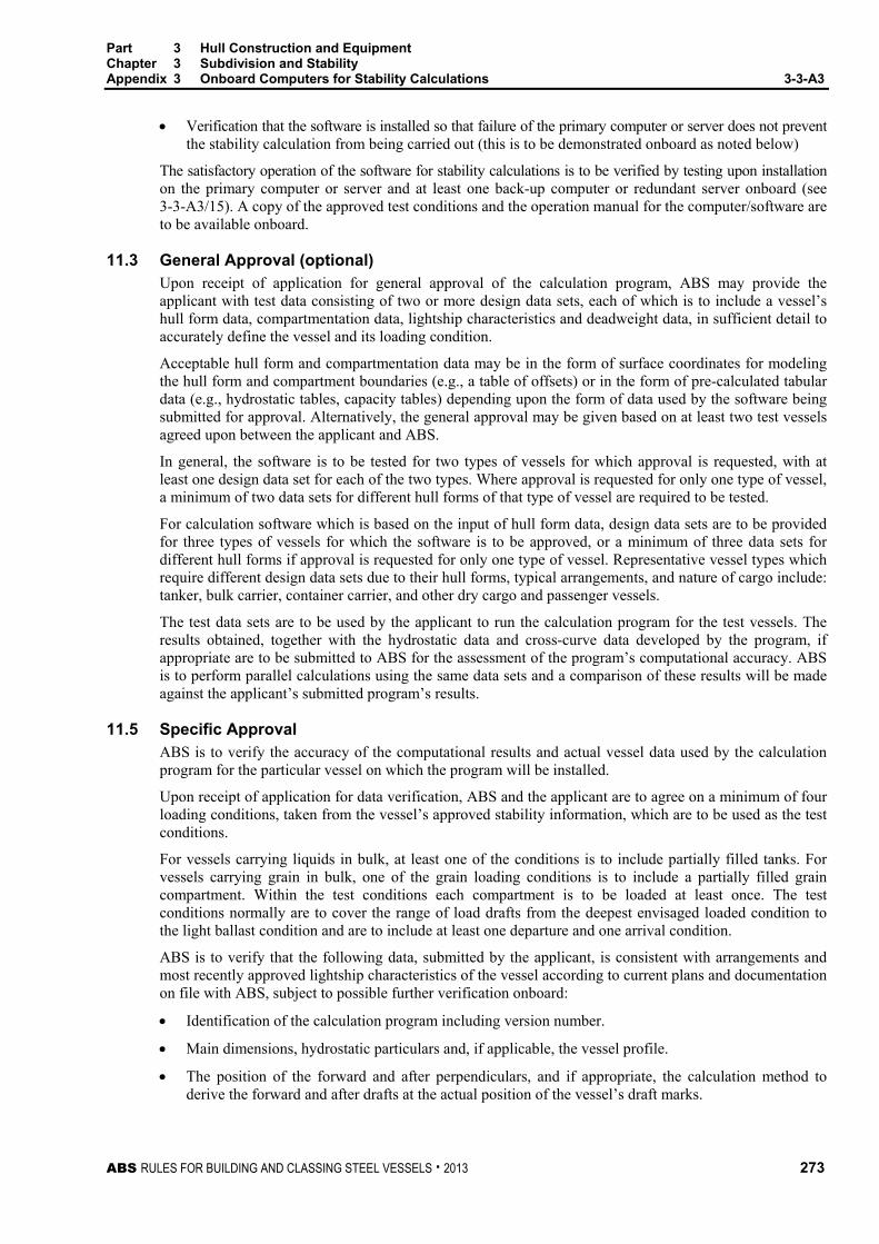
Part 3 Hull Construction and Equipment Chapter 3 Subdivision and Stability Appendix 3 Onboard Computers for Stability Calculations 3-3-A3
ABS RULES FOR BUILDING AND CLASSING STEEL VESSELS . 2013 273
• Verification that the software is installed so that failure of the primary computer or server does not prevent the stability calculation from being carried out (this is to be demonstrated onboard as noted below)
The satisfactory operation of the software for stability calculations is to be verified by testing upon installation on the primary computer or server and at least one back-up computer or redundant server onboard (see 3-3-A3/15). A copy of the approved test conditions and the operation manual for the computer/software are to be available onboard.
11.3 General Approval (optional) Upon receipt of application for general approval of the calculation program, ABS may provide the applicant with test data consisting of two or more design data sets, each of which is to include a vessel’s hull form data, compartmentation data, lightship characteristics and deadweight data, in sufficient detail to accurately define the vessel and its loading condition.
Acceptable hull form and compartmentation data may be in the form of surface coordinates for modeling the hull form and compartment boundaries (e.g., a table of offsets) or in the form of pre-calculated tabular data (e.g., hydrostatic tables, capacity tables) depending upon the form of data used by the software being submitted for approval. Alternatively, the general approval may be given based on at least two test vessels agreed upon between the applicant and ABS.
In general, the software is to be tested for two types of vessels for which approval is requested, with at least one design data set for each of the two types. Where approval is requested for only one type of vessel, a minimum of two data sets for different hull forms of that type of vessel are required to be tested.
For calculation software which is based on the input of hull form data, design data sets are to be provided for three types of vessels for which the software is to be approved, or a minimum of three data sets for different hull forms if approval is requested for only one type of vessel. Representative vessel types which require different design data sets due to their hull forms, typical arrangements, and nature of cargo include: tanker, bulk carrier, container carrier, and other dry cargo and passenger vessels.
The test data sets are to be used by the applicant to run the calculation program for the test vessels. The results obtained, together with the hydrostatic data and cross-curve data developed by the program, if appropriate are to be submitted to ABS for the assessment of the program’s computational accuracy. ABS is to perform parallel calculations using the same data sets and a comparison of these results will be made against the applicant’s submitted program’s results.
11.5 Specific Approval ABS is to verify the accuracy of the computational results and actual vessel data used by the calculation program for the particular vessel on which the program will be installed.
Upon receipt of application for data verification, ABS and the applicant are to agree on a minimum of four loading conditions, taken from the vessel’s approved stability information, which are to be used as the test conditions.
For vessels carrying liquids in bulk, at least one of the conditions is to include partially filled tanks. For vessels carrying grain in bulk, one of the grain loading conditions is to include a partially filled grain compartment. Within the test conditions each compartment is to be loaded at least once. The test conditions normally are to cover the range of load drafts from the deepest envisaged loaded condition to the light ballast condition and are to include at least one departure and one arrival condition.
ABS is to verify that the following data, submitted by the applicant, is consistent with arrangements and most recently approved lightship characteristics of the vessel according to current plans and documentation on file with ABS, subject to possible further verification onboard:
• Identification of the calculation program including version number.
• Main dimensions, hydrostatic particulars and, if applicable, the vessel profile.
• The position of the forward and after perpendiculars, and if appropriate, the calculation method to derive the forward and after drafts at the actual position of the vessel’s draft marks.

Part 3 Hull Construction and Equipment Chapter 3 Subdivision and Stability Appendix 3 Onboard Computers for Stability Calculations 3-3-A3
274 ABS RULES FOR BUILDING AND CLASSING STEEL VESSELS . 2013
• Vessel lightweight and center of gravity derived from the most recently approved inclining experiment or light weight check.
• Lines plan, offset tables or other suitable presentation of hull form data if necessary for ABS to model the vessel.
• Compartment definitions, including frame spacing, and centers of volume, together with capacity tables (sounding/ullage tables), free surface corrections, if appropriate
• Cargo and Consumables distribution for each loading condition.
Verification by ABS does not absolve the applicant and shipowner of responsibility for ensuring that the information programmed into the onboard computer software is consistent with the current condition of the vessel.
13 Operation Manual A simple and straightforward operation manual is to be provided, containing descriptions and instructions, as appropriate, for at least the following:
• Installation
• Function keys
• Menu displays
• Input and output data
• Required minimum hardware to operate the software
• Use of the test loading conditions
• Computer-guided dialogue steps
• List of warnings
15 Installation Testing To ensure correct working of the computer after the final or updated software has been installed, it is the responsibility of the vessel’s master to have test calculations carried out according to the following pattern in the presence of the Surveyor:
• From the approved test conditions at least one load case (other than lightship) is to be calculated. Note: Actual loading condition results are not suitable for checking the correct working of the computer.
• Normally, the test conditions are permanently stored in the computer.
Steps to be performed:
• Retrieve the test load case and start a calculation run; compare the stability results with those in the documentation.
• Change several items of deadweight (tank weights and the cargo weight) sufficiently to change the draft or displacement by at least 10%. The results are to be reviewed to ensure that they differ in a logical way from those of the approved test condition.
• Revise the above modified load condition to restore the initial test condition and compare the results. The relevant input and output data of the approved test condition are to been replicated.
• Alternatively, one or more test conditions shall be selected and the test calculation performed by entering all deadweight data for each selected test condition into the program as if it were a proposed loading. The results shall be verified as identical to the results in the approved copy of the test conditions.

Part 3 Hull Construction and Equipment Chapter 3 Subdivision and Stability Appendix 3 Onboard Computers for Stability Calculations 3-3-A3
ABS RULES FOR BUILDING AND CLASSING STEEL VESSELS . 2013 275
17 Periodical Testing It is the responsibility of the vessel’s master to check the accuracy of the onboard computer for stability calculations at each Annual Survey by applying at least one approved test condition.
If the Surveyor is not present for the computer check, a copy of the test condition results obtained by the computer check is to be retained onboard as documentation of satisfactory testing for the Surveyor’s verification.
At each Special Periodical Survey, this checking for all approved test loading conditions is to be done in presence of the surveyor.
The testing procedure is to be carried out in accordance with 3-3-A3/15.
19 Other Requirements The following features are to be provided to the software:
• Protection against unintentional or unauthorized modification of programs and data is to be provided.
• The program is to monitor operations and activate an alarm when the program is incorrectly or abnormally used.
• The program and any data stored in the system are to be protected from corruption by loss of power.
• Error messages with regard to limitations such as filling a compartment beyond capacity, or exceeding the assigned load line, etc. are to be included.

276 ABS RULES FOR BUILDING AND CLASSING STEEL VESSELS . 2013
P A R T C h a p t e r 4 : F i r e S a f e t y M e a s u r e s
3 C H A P T E R 4 Fire Safety Measures
CONTENTS SECTION 1 Structural Fire Protection .................................................................. 277
1 General ........................................................................................... 277 1.1 SOLAS Application ...................................................................... 277 1.3 Regulation ................................................................................... 277 1.5 Definitions .................................................................................... 277 1.7 Materials Containing Asbestos .................................................... 277
3 Passenger Vessels ......................................................................... 277 5 Cargo Vessel................................................................................... 277
5.1 All Vessels ................................................................................... 277 5.3 Tankers ........................................................................................ 277
7 Review Procedures ......................................................................... 278 7.1 Administration Review ................................................................. 278 7.3 ABS Review ................................................................................. 278

ABS RULES FOR BUILDING AND CLASSING STEEL VESSELS . 2013 277
P A R T S e c t i o n 1 : S t r u c t u r a l F i r e P r o t e c t i o n
3 C H A P T E R 4 Fire Safety Measures
S E C T I O N 1 Structural Fire Protection
1 General
1.1 SOLAS Application For classification purposes, the fire safety measures contained in the International Convention for the Safety of Life at Sea, 1974 (1974 SOLAS) as amended, are applicable to vessels of type, size and service coming under that Convention.
This Chapter does not relax the requirements in other Chapters of these Rules.
1.3 Regulation Regulation means the regulation contained in 1974 SOLAS, as amended. An abbreviated notation is used, e.g., Regulation II-2/5.2 means Regulation 5.2 of Chapter II-2.
1.5 Definitions See Regulation II-2/3.
1.7 Materials Containing Asbestos (1 July 2011) Installation of materials which contain asbestos is prohibited.
3 Passenger Vessels For Passenger vessels, the requirements in Part 5C, Chapter 7 are applicable.
5 Cargo Vessel
5.1 All Vessels For all cargo vessels as defined in Regulation 3.7, the relevant requirements in Part B: Regulation 4, 5, 6; Part C: Regulations 7, 8, 9, 10, 11; Part D: Regulation 13; and Part G: Regulations 19 and 20, Chapter II-2 of 1974 SOLAS, as amended, are applicable.
5.3 Tankers For tankers as defined in Regulations 3.48, Chapter II-2 of 1974 SOLAS, as amended, the following requirements are additional to 3-4-1/5.1.
5.3.1 Low Flash Point Cargoes (2010) For tankers intended for the carriage of cargoes having a flash point of 60°C (140°F) or less, the relevant requirements in Part A: Regulation 1; Part B: Regulation 4; Part C: Regulations 9, 10, 11; and Part E: Regulations 16, Chapter II-2 of 1974 SOLAS, as amended, are applicable. Furthermore, the requirements of Chapters 2, 14 and 15 of the Fire Safety Systems Code are also applicable.

Part 3 Hull Construction and Equipment Chapter 4 Fire Safety Measures Section 1 Structural Fire Protection 3-4-1
278 ABS RULES FOR BUILDING AND CLASSING STEEL VESSELS . 2013
For tankers with bow or stern loading and unloading connections, the provisions of SOLAS Regulations II-2/4.5.1.6, II-2/4.5.2.1 to II-2/4.5.2.3 inclusive and II-2/9.2.4.2.5 are to apply, unless alternative arrangements are acceptable to the Administration. This applies to the exterior boundaries of superstructures and deckhouses enclosing accommodation spaces which face the cargo shore connection, the overhanging decks which support such accommodation, the outboard sides of the superstructures and deckhouses for the specific distances from the boundaries which face the cargo shore connection.
5.3.2 High Flash Point Cargoes For tankers intended for the carriage of cargoes having a flash point above 60°C (140°F), the requirements in 3-4-1/5.1 are applicable, except that in lieu of the fixed fire extinguishing system required by Regulation II-2/10.7.1.3 they are to be fitted with a fixed deck foam system which is to comply with Chapter 14 of the Fire Safety Systems Code.
7 Review Procedures
7.1 Administration Review When the vessel is issued a Passenger Ship Safety Certificate, Cargo Ship Safety Equipment Certificate or Cargo Ship Safety Construction Certificate by the flag Administration or its agent other than ABS, such Certificate will be accepted as evidence that the vessel is in accordance with the applicable criteria in 1974 SOLAS as amended.
Where the Administration undertakes any part of the review and ABS is issuing the above certificate, the acceptance by the Administration will be required before the certificate is issued.
Compliance with the Rule requirements in addition to those in 1974 SOLAS, as amended, is to be verified by ABS.
7.3 ABS Review In all other cases, the required information and plan are to be submitted to ABS for review.

ABS RULES FOR BUILDING AND CLASSING STEEL VESSELS . 2013 279
P A R T C h a p t e r 5 : E q u i p m e n t
3 C H A P T E R 5 Equipment
CONTENTS SECTION 1 Anchoring, Mooring and Towing Equipment ................................... 281
1 General ........................................................................................... 281 3 Equipment Mass and Size .............................................................. 281 5 Tests ............................................................................................... 283 7 Anchor Types .................................................................................. 283 9 Hawsers and Towlines .................................................................... 283
9.1 All Vessels ................................................................................... 283 11 Windlass Support Structure and Cable Stopper ............................. 283
11.1 General........................................................................................ 283 11.3 Support Structure ........................................................................ 284 11.5 Trial ............................................................................................. 285
13 Hawse Pipes ................................................................................... 287 15 Bollard, Fairlead and Chocks .......................................................... 287
15.1 General........................................................................................ 287 15.3 Deck Fittings ................................................................................ 287 15.5 Safe Working Load (SWL) ........................................................... 287 15.7 Towing and Mooring Arrangements Plan .................................... 287 15.9 Emergency Towing Arrangements .............................................. 288
17 Chafing Chain for Emergency Towing Arrangements .................... 288 17.1 Scope .......................................................................................... 288 17.3 Qualification of Manufacturers ..................................................... 288 17.5 Materials ...................................................................................... 288 17.7 Design, Manufacture, Testing and Certification of Chafing
Chain ........................................................................................... 288 TABLE 1 Equipment for Self-propelled Ocean-going Vessels ............. 290 TABLE 2 Towline and Hawsers for Self-propelled Ocean-going
Vessels .................................................................................. 294 FIGURE 1 Effective Heights of Deck Houses......................................... 282 FIGURE 2 Direction of Forces and Weight ............................................. 286 FIGURE 3 Sign Convention .................................................................... 286 FIGURE 4 Typical Outboard Chafing Chain End ................................... 289

280 ABS RULES FOR BUILDING AND CLASSING STEEL VESSELS . 2013
SECTION 2 Mooring of Oil Carriers at Single Point Moorings ............................ 298 1 Application ....................................................................................... 298 3 Notation ........................................................................................... 298 5 Submission of Design Plans and Data ........................................... 298 7 Arrangements.................................................................................. 298
7.1 General ........................................................................................ 298 7.3 Bow Chain Stoppers .................................................................... 299 7.5 Bow Fairleads .............................................................................. 300 7.7 Pedestal Rollers........................................................................... 300 7.9 Winches or Capstans ................................................................... 300 7.11 Winch Storage Drum ................................................................... 300
9 Materials .......................................................................................... 300 TABLE 1 Required Arrangements by Vessel Deadweight ................... 299
ABS RULES FOR BUILDING AND CLASSING STEEL VESSELS . 2013 281
P A R T S e c t i o n 1 : A n c h o r i n g , M o o r i n g a n d T o w i n g E q u i p m e n t
3 C H A P T E R 5 Equipment
S E C T I O N 1 Anchoring, Mooring and Towing Equipment
1 General (2012) All vessels are to have a complete equipment of anchors and chains. The letter Á placed after the symbols of classification in the Record, thus: À A1 Á, will signify that the equipment of the vessel is in compliance with the requirements of the Rules, or with requirements corresponding to the service limitation noted in the vessel’s classification, which have been specially approved for the particular service. The mass per anchor of bower anchors, given in 3-5-1/Table 1, is for anchors of equal mass. The mass of individual anchors may vary 7% plus or minus from the tabular mass, provided that the combined mass of all anchors is not less than that required for anchors of equal mass. The total length of chain required to be carried onboard, as given in 3-5-1/Table 1, is to be reasonably divided between the two bower anchors.
Cables which are intended to form part of the equipment are not to be used as check chains when the vessel is launched. The inboard ends of the cables of the bower anchors are to be secured by efficient means. Two bower anchors and their cables are to be connected and positioned, ready for use. Where three anchors are given in 3-5-1/Table 1, the third anchor is intended as a spare bower anchor and is listed for guidance only; it is not required as a condition of classification. Means are to be provided for stopping each cable as it is paid out, and the windlass should be capable of heaving in either cable. The length of chain cable required by Table 3-5-1/Table 1 can be equally distributed between the two bower anchors connected and ready for use. Where the chain is arranged so that one anchor has a longer length for mooring it is to be verified that the windlass has sufficient capability for heaving in the longer length of chain. Suitable arrangements are to be provided for securing the anchors and stowing the cables.
Equipment Number calculations for unconventional vessels with unique topside arrangements or operational profiles may be specially considered. Such consideration may include accounting for additional wind areas of widely separated deckhouses or superstructures in the equipment number calculations or equipment sizing based on direct calculations. However, in no case may direct calculations be used to reduce the equipment size to be less than that required by 3-5-1/3.
3 Equipment Mass and Size (2012) The requirements herein are intended for temporary mooring of a vessel within a harbor or other areas of sheltered water. The “Equipment Number” equation is based on 2.5 m/s (8.2 ft/s) current, 25 m/s (49 knots) wind and a scope of 6 through 10, the scope being the ratio of length of chain paid out to the water depth. Anchors and chains are to be in accordance with 3-5-1/Table 1 and the numbers, mass and sizes of these are to be regulated by the equipment number (EN) obtained from the following equation:
Equipment Number = k∆2/3 + mBh + nA
where
k = 1.0 (1.0, 1.012)
m = 2 (2, 0.186)
n = 0.1 (0.1, 0.00929)
∆ = molded displacement, as defined in 3-1-1/11.1
B = molded breadth, as defined in 3-1-1/5, in m (ft)

Part 3 Hull Construction and Equipment Chapter 5 Equipment Section 1 Anchoring, Mooring and Towing Equipment 3-5-1
282 ABS RULES FOR BUILDING AND CLASSING STEEL VESSELS . 2013
h = a + h1 + h2 + h3 + . . ., as shown in 3-5-1/Figure 1. In the calculation of h, sheer, camber and trim may be neglected
a = freeboard, in m (ft), from the summer load waterline amidships
h1, h2, h3 … = height, in m (ft), on the centerline of each tier of houses having a breadth greater than B/4
A = profile area, in m2 (ft2), of the hull, superstructure and houses above the summer load waterline which are within the Rule length. Superstructures or deck houses having a breadth at any point no greater than 0.25B may be excluded. Screens and bulwarks more than 1.5 m (4.9 ft) in height are to be regarded as parts of houses when calculating h and A. The height of the hatch coamings and that of any deck cargo, such as containers, may be disregarded when determining h and A. With regard to determining A, when a bulwark is more than 1.5 m (4.9 ft) high, the area shown below as A2 should be included in A.
A2
F.P.
1.5
m (4
.9 ft
)
FIGURE 1 Effective Heights of Deck Houses
A B
3
2
1
a
h
h
h
B/8

Part 3 Hull Construction and Equipment Chapter 5 Equipment Section 1 Anchoring, Mooring and Towing Equipment 3-5-1
ABS RULES FOR BUILDING AND CLASSING STEEL VESSELS . 2013 283
5 Tests Tests are to be in accordance with the requirements of Part 2, Chapter 2 for the respective sizes of anchors and chains. See Section 2-2-1 and Section 2-2-2.
7 Anchor Types Anchors are to be of the stockless type. The mass of the head of a stockless anchor, including pins and fittings, is not to be less than three-fifths of the total mass of the anchor. Where specifically requested by the Owners, ABS is prepared to give consideration to the use of special types of anchors and where these are of proven superior holding ability, consideration may also be given to some reduction in the mass, up to a maximum of 25% from the mass specified in 3-5-1/Table 1. In such cases, the notation RW will be made in the Record.
9 Hawsers and Towlines
9.1 All Vessels (1995) Except as indicated in 3-5-1/15.7, hawsers and towlines are not required as a condition of classification. The hawsers and towlines listed in 3-5-1/Table 2 are intended as a guide. Where the tabular breaking strength exceeds 490 kN (50,000 kgf, 110,200 lbf), the breaking strength and the number of individual hawsers given in the Table may be modified, provided their product is not less than that of the breaking strength and the number of hawsers given in the Table. For vessels having an A/EN ratio greater than 0.9 for SI or MKS units (9.7 for US units), the number of hawsers given in 3-5-1/Table 2 is to be increased by the number given below.
A/EN Ratio Increase
number of hawsers by
SI Units MKS Units U.S. Units
Above 0.9 up to 1.1 above 9.7 up to 11.8 1 Above 1.1 up to 1.2 above 11.8 up to 12.9 2
above 1.2 above 12.9 3
where
A = defined in 3-5-1/3
EN = determined by the equation in 3-5-1/3
11 Windlass Support Structure and Cable Stopper
11.1 General (2004) Construction and installation of all windlasses used for anchoring are to be carried out in accordance with 4-1-1/5 and Section 4-5-1. Where fitted, an independent cable stopper and its components are to be adequate for the load imposed. The arrangements and details of the cable stopper are to be submitted for review.
The windlass supporting structures are to meet the requirements in 3-5-1/11.3. Where the mooring winch is integral with the windlass, it is to be considered as a part of the windlass for the purpose of said paragraph.

Part 3 Hull Construction and Equipment Chapter 5 Equipment Section 1 Anchoring, Mooring and Towing Equipment 3-5-1
284 ABS RULES FOR BUILDING AND CLASSING STEEL VESSELS . 2013
11.3 Support Structure (2004) The windlass is to be bolted down to a substantial foundation, which is to meet the following load cases and associated criteria.
11.3.1 Operating Loads 11.3.1(a) Load on Windlass Support Structure (2006). The following load is to be applied in the direction of the chain.
With cable stopper not attached to windlass: 45% of B.S.
With cable stopper attached to windlass: 80% of B.S.
Without cable stopper: 80% of B.S.
B.S. = minimum breaking strength of the chain, as indicated in 2-2-2/Tables 2 and 3 of the Rules for Materials and Welding (Part 2).
11.3.1(b) Load on Cable Stopper and Support Structure (2006). A load of 80% of B.S. is to be applied in the direction of the chain.
11.3.1(c) Allowable Stress (2006). The stresses in the structures supporting the windlass and cable stopper are not to exceed the yield point.
11.3.2 Sea Loads 11.3.2(a) Pressures. The following pressures and associated areas are to be applied (see 3-5-1/Figure 2):
- 200 kN/m2 (20.4 tf/m2, 4178 lbf/ft2) normal to the shaft axis and away from the forward perpendicular, over the projected area in this direction,
- 150 kN/m2 (15.3 tf/m2, 3133 lbf/ft2) parallel to the shaft axis and acting both inboard and outboard separately, over the multiple of f times the projected area in this direction,
where f is defined as:
f = 1 + B/H, f need not be taken as greater than 2.5
B = width of windlass measured parallel to the shaft axis
H = overall height of windlass.
11.3.2(b) Forces. Forces in the bolts, chocks and stoppers securing the windlass to the deck are to be calculated. The windlass is supported by N groups of bolts, each containing one or more bolts, see 3-5-1/Figure 2.
i) Axial Forces. The aggregate axial force Ri in respective group of bolts (or bolt) i, positive in tension, may be calculated from the following equations:
Rxi = Px hxi Ai/Ix
Ryi = Py hyi Ai/Iy
and
Ri = Rxi + Ryi – Rsi
where
Px = force, kN (tf, lbf), acting normal to the shaft axis
Py = force, kN (tf, lbf), acting parallel to the shaft axis, either inboard or outboard, whichever gives the greater force in bolt group i
h = shaft height above the windlass mounting, cm (in.)

Part 3 Hull Construction and Equipment Chapter 5 Equipment Section 1 Anchoring, Mooring and Towing Equipment 3-5-1
ABS RULES FOR BUILDING AND CLASSING STEEL VESSELS . 2013 285
xi, yi = x and y coordinates of bolt group i from the centroid of all N bolt groups, positive in the direction opposite to that of the applied force, cm (in.)
Ai = cross-sectional area of all bolts in group i, cm2 (in2)
Ix = Ai xi2 for N bolt groups
Iy = Ai yi2 for N bolt groups
Rsi = static reaction at bolt group i, due to weight of windlass.
ii) Shear forces. Aggregated shear forces, Fxi, Fyi, applied to the respective bolt group, i, of bolts, and the resultant combined force, Fi, may be calculated from:
Fxi = (Px – gM)/N
Fyi = (Py – gM)/N
and
Fi = ( 2xiF + 2
yiF )0.5
where:
= coefficient of friction (0.5)
M = mass of windlass, in tonnes (Ltons)
g = gravity: 9.81 m/sec2 (32.2 ft/sec2)
N = number of groups of bolts
The axial tensile/compressive and lateral forces from the above equations are also to be considered in the design of the supporting structure.
11.3.2(c) Stresses in Bolts. Tensile axial stresses in the individual bolts in each group of bolts i are to be calculated. The horizontal forces, Fxi and Fyi, are normally to be reacted by shear chocks. Where “fitted” bolts are designed to support these shear forces in one or both directions, the von Mises equivalent stresses in the individual “fitted” bolts are to be calculated and compared to the stress under proof load. Where pourable resins are incorporated in the holding down arrangements, due account is to be taken in the calculations.
11.3.2(d) Allowable Stress
i) Bolts. The safety factor against bolt proof strength is to be not less than 2.0.
ii) Supporting Structures. The stresses in the above deck framing and the hull structure supporting the windlass are not to exceed the following values.
Bending Stress 85% of the yield strength of the material
Shearing Stress 60% of the yield strength of the material
11.5 Trial See 3-7-2/1.

Part 3 Hull Construction and Equipment Chapter 5 Equipment Section 1 Anchoring, Mooring and Towing Equipment 3-5-1
286 ABS RULES FOR BUILDING AND CLASSING STEEL VESSELS . 2013
FIGURE 2 Direction of Forces and Weight (2004)
Py
H
h
W
Px
Fore
Px
PyCenterline of Vessel
Centerline ofWindlass
Note:Py to be examined from both inboard and outboarddirections separately - see 3-5-1/11.3.2(a). Thesign convention for yi is reversed when Py is fromthe opposite direction as shown.
B
FIGURE 3
Sign Convention (2004)
Centerline ofWindlass
Centroid of Bolt Groups
Px
Py
y3 (+ve)
y4 (+ve)
y2 (+ve)
y1 (+ve)
x1 (+ve)x2 (+ve)x4 (-ve)
x3 (-ve)
Coordinates xi and yi are shown as eitherpositive (+ve) or negative (-ve).

Part 3 Hull Construction and Equipment Chapter 5 Equipment Section 1 Anchoring, Mooring and Towing Equipment 3-5-1
ABS RULES FOR BUILDING AND CLASSING STEEL VESSELS . 2013 287
13 Hawse Pipes Hawse pipes are to be of ample size and strength. They are to have full rounded flanges and the least possible lead, in order to minimize the nip on the cables. They are to be securely attached to thick doubling or insert plates by continuous welds the size of which are to be in accordance with Section 3-2-19 for the plating thickness and type of joint selected. When in position, they are to be thoroughly tested for watertightness by means of a hose in which the water pressure is not to be less than 2.06 bar (2.1 kgf/cm2, 30 psi). Hawse pipes for stockless anchors are to provide ample clearances. The anchors are to be shipped and unshipped so that the Surveyor may be satisfied that there is no risk of the anchor jamming in the hawse pipe. Care is to be taken to ensure a fair lead for the chain from the windlass to the hawse pipes and to the chain pipes.
15 Bollard, Fairlead and Chocks (2007)
15.1 General The arrangements and details of deck fittings used for mooring operations and/or towing operations at bow, sides and stern are to comply with the requirements of this section. The requirements for the supporting structures of these deck fittings are specified in 3-2-7/4.
15.3 Deck Fittings The size of deck fittings is to be in accordance with recognized standards (e.g. ISO3913 Shipbuilding Welded Steel Bollards). The design load used to assess deck fittings and their attachments to the hull are to be in accordance with the requirements as specified in 3-2-7/4.
15.5 Safe Working Load (SWL) The requirements on SWL apply for a single post basis (no more than one turn of one cable).
15.5.1 Mooring Operations The SWL is not to exceed 80% of the design load per 3-2-7/4.3.1.
15.5.2 Towing Operations The SWL used for normal towing operations (e.g., harbor/maneuvering) is not to exceed 80% of the design load per 3-2-7/4.3.2(a) and the SWL used for other towing operations (e.g., escort) is not to exceed the design load per 3-2-7/4.3.2(b). For deck fittings used for both normal and other towing operations, the design load of 3-2-7/4.3.2 is to be used.
15.5.3 Marking and Plan 15.5.3(a) Marking. The SWL of each deck fitting is to be marked (by weld bead or equivalent) on the deck fittings used for towing/mooring.
15.5.3(b) Plan. The towing and mooring arrangements plan mentioned in 3-5-1/15.7 is to define the method of use of mooring lines and/or towing lines.
15.7 Towing and Mooring Arrangements Plan The SWL for the intended use for each deck fitting is to be noted in the towing and mooring arrangements plan available on board for the guidance of the Master.
Information provided on the plan is to include in respect of each deck fitting:
• Location on the ship;
• Fitting type;
• SWL;
• Purpose (mooring/harbor towing/escort towing); and
• Manner of applying towing or mooring line load including limiting fleet angles.

Part 3 Hull Construction and Equipment Chapter 5 Equipment Section 1 Anchoring, Mooring and Towing Equipment 3-5-1
288 ABS RULES FOR BUILDING AND CLASSING STEEL VESSELS . 2013
Note: Where the arrangements and details of deck fittings and their supporting structures are designed based on the mooring arrangements as permitted in Note 2 of 3-2-7/4.3.1(a), the arrangement of mooring lines showing number of lines together with the breaking strength of each mooring line are to be clearly indicated on the plan.
This information is to be incorporated into the pilot card in order to provide the pilot proper information on harbor/escorting operations.
15.9 Emergency Towing Arrangements (1 January 1996) Tankers of 20,000 tonnes deadweight and above, including oil tankers, chemical tankers and gas carriers, are to be fitted with an emergency towing arrangement at both ends complying with Maritime Safety Committee Resolution MSC 35(63). Written approval by the flag Administration of the emergency towing arrangements will be accepted as evidence of compliance with this paragraph.
17 Chafing Chain for Emergency Towing Arrangements (2005)
17.1 Scope These requirements apply to the chafing chain for chafing gear of two types of Emergency Towing Arrangement (ETA), those with a specified safe working load (SWL) of 1000 kN (ETA1000) and those with a specified safe working load of 2000 kN (ETA2000). Chafing chains other than those specified can be used subject to special agreement with ABS.
17.3 Qualification of Manufacturers Chafing chain is to be manufactured by works approved by ABS, in accordance with 2-2-2/7.1 or in accordance with the ABS Guide for Certification of Offshore Mooring Chain.
17.5 Materials Materials used for the manufacture of chafing chain are to meet the requirements of 2-2-2/7.11 or in accordance with the ABS Guide for Certification of Offshore Mooring Chain.
17.7 Design, Manufacture, Testing and Certification of Chafing Chain 17.7.1
Chafing chain is to be designed, manufactured, tested and certified in accordance with the requirements of Section 2-2-2 or in accordance with the ABS Guide for Certification of Offshore Mooring Chain.
17.7.2 The common link is to be of stud link type grade 2a, 2b or 3a, 3b Anchor Chain, or grade RQ3, RQ3S, RQ4 Mooring Chain.
17.7.3 The arrangement at the end connected to the strongpoint and the dimensions of the chafing chain are determined by the type of ETA. The other end of the chafing chain is to be fitted with a pear-shaped open link allowing connection to a shackle corresponding to the type of ETA and chain cable grade. A typical arrangement of this chain end is shown in 3-5-1/Figure 4.
17.7.4 The chafing chain is to be able to withstand a breaking load not less than twice the SWL. For each type of ETA, the nominal diameter of common link for chafing chains is to comply with the value indicated below.
Type of ETA Nominal Diameter of Common Link, d, min.
Grade 2 Grade 3 ETA1000 62 mm 52 mm ETA2000 90 mm 76 mm

Part 3 Hull Construction and Equipment Chapter 5 Equipment Section 1 Anchoring, Mooring and Towing Equipment 3-5-1
ABS RULES FOR BUILDING AND CLASSING STEEL VESSELS . 2013 289
FIGURE 4 Typical Outboard Chafing Chain End (2005)
Pear shapedopen link
Studlessend link
Enlargedlink
Common links(diameter = d)
1.1d 1.2d
d
1.2d
2.2d2d
Towardstowing pennant
5.75dapprox.

Part 3 Hull Construction and Equipment Chapter 5 Equipment Section 1 Anchoring, Mooring and Towing Equipment 3-5-1
290 ABS RULES FOR BUILDING AND CLASSING STEEL VESSELS . 2013
TABLE 1 Equipment for Self-propelled Ocean-going Vessels
SI, MKS Units Stockless Bower Anchors Chain Cable Stud Link Bower Chain Diameter
Equipment Numeral
Equipment Number* Number
Mass per Anchor,
kg Length,
m
Normal- Strength Steel
(Grade 1), mm
High- Strength Steel
(Grade 2), mm
Extra High-Strength Steel
(Grade 3), mm
U6 150 2 480 275 22 19 U7 175 2 570 302.5 24 20.5 U8 205 3 660 302.5 26 22 20.5 U9 240 3 780 330 28 24 22 U10 280 3 900 357.5 30 26 24
U11 320 3 1020 357.5 32 28 24 U12 360 3 1140 385 34 30 26 U13 400 3 1290 385 36 32 28 U14 450 3 1440 412.5 38 34 30 U15 500 3 1590 412.5 40 34 30
U16 550 3 1740 440 42 36 32 U17 600 3 1920 440 44 38 34 U18 660 3 2100 440 46 40 36 U19 720 3 2280 467.5 48 42 36 U20 780 3 2460 467.5 50 44 38
U21 840 3 2640 467.5 52 46 40 U22 910 3 2850 495 54 48 42 U23 980 3 3060 495 56 50 44 U24 1060 3 3300 495 58 50 46 U25 1140 3 3540 522.5 60 52 46
U26 1220 3 3780 522.5 62 54 48 U27 1300 3 4050 522.5 64 56 50 U28 1390 3 4320 550 66 58 50 U29 1480 3 4590 550 68 60 52 U30 1570 3 4890 550 70 62 54
U31 1670 3 5250 577.5 73 64 56 U32 1790 3 5610 577.5 76 66 58 U33 1930 3 6000 577.5 78 68 60 U34 2080 3 6450 605 81 70 62 U35 2230 3 6900 605 84 73 64
U36 2380 3 7350 605 87 76 66 U37 2530 3 7800 632.5 90 78 68 U38 2700 3 8300 632.5 92 81 70 U39 2870 3 8700 632.5 95 84 73 U40 3040 3 9300 660 97 84 76

Part 3 Hull Construction and Equipment Chapter 5 Equipment Section 1 Anchoring, Mooring and Towing Equipment 3-5-1
ABS RULES FOR BUILDING AND CLASSING STEEL VESSELS . 2013 291
TABLE 1 (continued) Equipment for Self-propelled Ocean-going Vessels
SI, MKS Units Stockless Bower Anchors Chain Cable Stud Link Bower Chain Diameter
Equipment Numeral
Equipment Number* Number
Mass per Anchor,
kg Length,
m
Normal- Strength Steel
(Grade 1), mm
High- Strength Steel
(Grade 2), mm
Extra High-Strength Steel
(Grade 3), mm
U41 3210 3 9900 660 100 87 78 U42 3400 3 10500 660 102 90 78 U43 3600 3 11100 687.5 105 92 81 U44 3800 3 11700 687.5 107 95 84 U45 4000 3 12300 687.5 111 97 87
U46 4200 3 12900 715 114 100 87 U47 4400 3 13500 715 117 102 90 U48 4600 3 14100 715 120 105 92 U49 4800 3 14700 742.5 122 107 95 U50 5000 3 15400 742.5 124 111 97
U51 5200 3 16100 742.5 127 111 97 U52 5500 3 16900 742.5 130 114 100 U53 5800 3 17800 742.5 132 117 102 U54 6100 3 18800 742.5 — 120 107 U55 6500 3 20000 770 — 124 111
U56 6900 3 21500 770 — 127 114 U57 7400 3 23000 770 — 132 117 U58 7900 3 24500 770 — 137 122 U59 8400 3 26000 770 — 142 127 U60 8900 3 27500 770 — 147 132 U61 9400 3 29000 770 — 152 132
U62 10000 3 31000 770 — — 137 U63 10700 3 33000 770 — — 142 U64 11500 3 35500 770 — — 147 U65 12400 3 38500 770 — — 152 U66 13400 3 42000 770 — — 157 U67 14600 3 46000 770 — — 162
* For intermediate values of equipment number, use equipment complement in sizes and weights given for the lower equipment
number in the table.

Part 3 Hull Construction and Equipment Chapter 5 Equipment Section 1 Anchoring, Mooring and Towing Equipment 3-5-1
292 ABS RULES FOR BUILDING AND CLASSING STEEL VESSELS . 2013
TABLE 1 Equipment for Self-propelled Ocean-going Vessels
US Units Stockless Bower Anchors Chain Cable Stud Link Bower Chain Diameter
Equipment Numeral
Equipment Number* Number
Mass per Anchor, pounds
Length, fathoms
Normal- Strength Steel
(Grade 1), inches
High- Strength Steel
(Grade 2), inches
Extra High-Strength Steel
(Grade 3), inches
U6 150 2 1060 150 7/8 3/4 U7 175 2 1255 165 15/16 13/16 U8 205 3 1455 165 1 7/8 13/16 U9 240 3 1720 180 1 1/8 15/16 7/8 U10 280 3 1985 195 1 3/16 1 15/16
U11 320 3 2250 195 1 1/4 1 1/8 15/16 U12 360 3 2510 210 1 5/16 1 3/16 1 U13 400 3 2840 210 1 7/16 1 1/4 1 1/8 U14 450 3 3170 225 1 1/2 1 5/16 1 3/16 U15 500 3 3500 225 1 9/16 1 5/16 1 3/16
U16 550 3 3830 240 1 5/8 1 7/16 1 1/4 U17 600 3 4230 240 1 3/4 1 1/2 1 5/16 U18 660 3 4630 240 1 13/16 1 9/16 1 7/16 U19 720 3 5020 255 1 7/8 1 5/8 1 7/16 U20 780 3 5420 255 2 1 3/4 1 1/2
U21 840 3 5820 255 2 1/16 1 13/16 1 9/16 U22 910 3 6280 270 2 1/8 1 7/8 1 5/8 U23 980 3 6740 270 2 3/16 1 15/16 1 3/4 U24 1060 3 7270 270 2 5/16 2 1 13/16 U25 1140 3 7800 285 2 3/8 2 1/16 1 13/16
U26 1220 3 8330 285 2 7/16 2 1/8 1 7/8 U27 1300 3 8930 285 2 1/2 2 3/16 2 U28 1390 3 9520 300 2 5/8 2 5/16 2 U29 1480 3 10120 300 2 11/16 2 3/8 2 1/16 U30 1570 3 10800 300 2 3/4 2 7/16 2 1/8
U31 1670 3 11600 315 2 7/8 2 1/2 2 3/16 U32 1790 3 12400 315 3 2 5/8 2 5/16 U33 1930 3 13200 315 3 1/16 2 11/16 2 3/8 U34 2080 3 14200 330 3 3/16 2 3/4 2 7/16 U35 2230 3 15200 330 3 5/16 2 7/8 2 1/2
U36 2380 3 16200 330 3 7/16 3 2 5/8 U37 2530 3 17200 345 3 9/16 3 1/16 2 11/16 U38 2700 3 18300 345 3 5/8 3 3/16 2 3/4 U39 2870 3 19200 345 3 3/4 3 5/16 2 7/8 U40 3040 3 20500 360 3 7/8 3 5/16 3
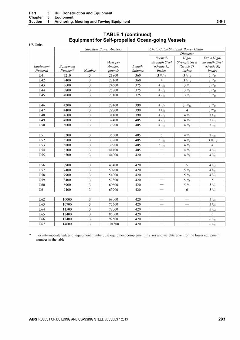
Part 3 Hull Construction and Equipment Chapter 5 Equipment Section 1 Anchoring, Mooring and Towing Equipment 3-5-1
ABS RULES FOR BUILDING AND CLASSING STEEL VESSELS . 2013 293
TABLE 1 (continued) Equipment for Self-propelled Ocean-going Vessels
US Units Stockless Bower Anchors Chain Cable Stud Link Bower Chain Diameter
Equipment Numeral
Equipment Number* Number
Mass per Anchor, pounds
Length, fathoms
Normal- Strength Steel
(Grade 1), inches
High- Strength Steel
(Grade 2), inches
Extra High-Strength Steel
(Grade 3), inches
U41 3210 3 21800 360 3 15/16 3 7/16 3 1/16 U42 3400 3 23100 360 4 3 9/16 3 1/16 U43 3600 3 24500 375 4 1/8 3 5/8 3 3/16 U44 3800 3 25800 375 4 1/4 3 3/4 3 5/16 U45 4000 3 27100 375 4 3/8 3 7/8 3 7/16
U46 4200 3 28400 390 4 1/2 3 15/16 3 7/16 U47 4400 3 29800 390 4 5/8 4 3 9/16 U48 4600 3 31100 390 4 3/4 4 1/8 3 5/8 U49 4800 3 32400 405 4 3/4 4 1/4 3 3/4 U50 5000 3 33900 405 4 7/8 4 3/8 3 7/8
U51 5200 3 35500 405 5 4 3/8 3 7/8 U52 5500 3 37200 405 5 1/8 4 1/2 3 15/16 U53 5800 3 39200 405 5 1/8 4 5/8 4 U54 6100 3 41400 405 — 4 3/4 4 1/4 U55 6500 3 44000 420 — 4 7/8 4 3/8
U56 6900 3 47400 420 — 5 4 1/2 U57 7400 3 50700 420 — 5 1/8 4 5/8 U58 7900 3 54000 420 — 5 3/8 4 3/4 U59 8400 3 57300 420 — 5 5/8 5 U60 8900 3 60600 420 — 5 3/4 5 1/8 U61 9400 3 63900 420 — 6 5 1/8
U62 10000 3 68000 420 — — 5 3/8 U63 10700 3 72500 420 — — 5 5/8 U64 11500 3 78000 420 — — 5 3/4 U65 12400 3 85000 420 — — 6 U66 13400 3 92500 420 — — 6 1/8 U67 14600 3 101500 420 — — 6 3/8
* For intermediate values of equipment number, use equipment complement in sizes and weights given for the lower equipment
number in the table.

Part 3 Hull Construction and Equipment Chapter 5 Equipment Section 1 Anchoring, Mooring and Towing Equipment 3-5-1
294 ABS RULES FOR BUILDING AND CLASSING STEEL VESSELS . 2013
TABLE 2 Towline and Hawsers for Self-propelled Ocean-going Vessels
SI & MKS Units
Equipment Numeral
Equipment Number*
Towline Wire or Rope Hawsers
Length, m
Breaking Strength,
Number
Length of Each,
m
Breaking Strength,
KN kgf kN kgf U6 150 180 98.0 10000 3 120 54.0 5500 U7 175 180 112.0 11400 3 120 59.0 6000 U8 205 180 129.0 13200 4 120 64.0 6500 U9 240 180 150.0 15300 4 120 69.0 7000 U10 280 180 174.0 17700 4 140 74.0 7500
U11 320 180 207.0 21100 4 140 78.0 8000 U12 360 180 224.0 22800 4 140 88.0 9000 U13 400 180 250.0 25500 4 140 98.0 10000 U14 450 180 277.0 28200 4 140 108.0 11000 U15 500 190 306.0 31200 4 160 123.0 12500
U16 550 190 338.0 34500 4 160 132.0 13500 U17 600 190 370.0 37800 4 160 147.0 15000 U18 660 190 406.0 41400 4 160 157.0 16000 U19 720 190 441.0 45000 4 170 172.0 17500 U20 780 190 479.0 48900 4 170 186.0 19000
U21 840 190 518.0 52800 4 170 201.0 20500 U22 910 190 559.0 57000 4 170 216.0 22000 U23 980 200 603.0 61500 4 180 230.0 23500 U24 1060 200 647.0 66000 4 180 250.0 25500 U25 1140 200 691.0 70500 4 180 270.0 27500
U26 1220 200 738.0 75300 4 180 284.0 29000 U27 1300 200 786.0 80100 4 180 309.0 31500 U28 1390 200 836.0 85200 4 180 324.0 33000 U29 1480 220 888.0 90600 5 190 324.0 33000 U30 1570 220 941.0 96000 5 190 333.0 34000
U31 1670 220 1024.0 104400 5 190 353.0 36000 U32 1790 220 1109.0 113100 5 190 378.0 38500 U33 1930 220 1168.0 119100 5 190 402.0 41000 U34 2080 240 1259.0 128400 5 200 422.0 43000 U35 2230 240 1356.0 138300 5 200 451.0 46000
U36 2380 240 1453.0 148200 5 200 480.0 49000 U37 2530 260 1471.0 150000 6 200 480.0 49000 U38 2700 260 1471.0 150000 6 200 490.0 50000 U39 2870 260 1471.0 150000 6 200 500.0 51000 U40 3040 280 1471.0 150000 6 200 520.0 53000

Part 3 Hull Construction and Equipment Chapter 5 Equipment Section 1 Anchoring, Mooring and Towing Equipment 3-5-1
ABS RULES FOR BUILDING AND CLASSING STEEL VESSELS . 2013 295
TABLE 2 (continued) Towline and Hawsers for Self-propelled Ocean-going Vessels
SI & MKS Units
Equipment Numeral
Equipment Number*
Towline Wire or Rope Hawsers
Length, m
Breaking Strength,
Number
Length of Each,
m
Breaking Strength,
KN kgf kN kgf U41 3210 280 1471.0 150000 6 200 554.0 56500 U42 3400 280 1471.0 150000 6 200 588.0 60000 U43 3600 300 1471.0 150000 6 200 618.0 63000 U44 3800 300 1471.0 150000 6 200 647.0 66000 U45 4000 300 1471.0 150000 7 200 647.0 66000
U46 4200 300 1471.0 150000 7 200 657.0 67000 U47 4400 300 1471.0 150000 7 200 667.0 68000 U48 4600 300 1471.0 150000 7 200 677.0 69000 U49 4800 300 1471.0 150000 7 200 686.0 70000 U50 5000 300 1471.0 150000 8 200 686.0 70000 U51 5200 300 1471.0 150000 8 200 696.0 71000 U52 5500 300 1471.0 150000 8 200 706.0 72000 U53 5800 300 1471.0 150000 9 200 706.0 72000 U54 6100 300 1471.0 150000 9 200 716.0 73000 U55 6500 300 1471.0 150000 9 200 726.0 74000
U56 6900 300 1471.0 150000 10 200 726.0 74000 U57 7400 300 1471.0 150000 11 200 726.0 74000 U58 7900 — — — 12 200 736.0 75000 U59 8400 — — — 12 200 736.0 75000 U60 8900 — — — 13 200 736.0 75000 U61 9400 — — — 14 200 736.0 75000
U62 10000 — — — 15 200 736.0 75000 U63 10700 — — — 16 200 736.0 75000 U64 11500 — — — 17 200 736.0 75000 U65 12400 — — — 18 200 736.0 75000 U66 13400 — — — 19 200 736.0 75000 U67 14600 — — — 21 200 736.0 75000
* For intermediate values of equipment number, use equipment complement in sizes and weights given for the lower equipment
number in the table.

Part 3 Hull Construction and Equipment Chapter 5 Equipment Section 1 Anchoring, Mooring and Towing Equipment 3-5-1
296 ABS RULES FOR BUILDING AND CLASSING STEEL VESSELS . 2013
TABLE 2 Towline and Hawsers for Self-propelled Ocean-going Vessels
US Units
Equipment Numeral
Equipment Number*
Towline Wire or Rope Hawsers
Length, Fathoms
Breaking Strength, Pounds Number
Length of Each
Fathoms
Breaking Strength, Pounds
U6 150 98 22000 3 66 12100 U7 175 98 25100 3 66 13200 U8 205 98 29100 4 66 14300 U9 240 98 33700 4 66 15400
U10 280 98 39000 4 77 16500
U11 320 98 46500 4 77 17600 U12 360 98 50300 4 77 19800 U13 400 98 56200 4 77 22000 U14 450 98 62200 4 77 24200 U15 500 104 68800 4 88 27600
U16 550 104 76000 4 88 29800 U17 600 104 83300 4 88 33100 U18 660 104 91200 4 88 35300 U19 720 104 99200 4 93 38600 U20 780 104 107800 4 93 41900
U21 840 104 116400 4 93 45200 U22 910 104 125600 4 93 48500 U23 980 109 135500 4 98 51800 U24 1060 109 145500 4 98 56200 U25 1140 109 155400 4 98 60600
U26 1220 109 166000 4 98 63900 U27 1300 109 176500 4 98 69400 U28 1390 109 187800 4 98 72800 U29 1480 120 199700 5 104 72800 U30 1570 120 211500 5 104 75000
U31 1670 120 230000 5 104 79400 U32 1790 120 249500 5 104 84900 U33 1930 120 262500 5 104 90400 U34 2080 131 283000 5 109 94800 U35 2230 131 305000 5 109 101400
U36 2380 131 326500 5 109 108000 U37 2530 142 330500 6 109 108000 U38 2700 142 330500 6 109 110200 U39 2870 142 330500 6 109 112400 U40 3040 153 330500 6 109 116800

Part 3 Hull Construction and Equipment Chapter 5 Equipment Section 1 Anchoring, Mooring and Towing Equipment 3-5-1
ABS RULES FOR BUILDING AND CLASSING STEEL VESSELS . 2013 297
TABLE 2 (continued) Towline and Hawsers for Self-propelled Ocean-going Vessels
US Units Towline Wire or Rope Hawsers
Equipment Numeral
Equipment Number*
Length, Fathoms
Breaking Strength, Pounds Number
Length of Each
Fathoms
Breaking Strength, Pounds
U41 3210 153 330500 6 109 124600 U42 3400 153 330500 6 109 132300 U43 3600 164 330500 6 109 138900 U44 3800 164 330500 6 109 145500 U45 4000 164 330500 7 109 145500
U46 4200 164 330500 7 109 147700 U47 4400 164 330500 7 109 149900 U48 4600 164 330500 7 109 152100 U49 4800 164 330500 7 109 154300 U50 5000 164 330500 8 109 154300
U51 5200 164 330500 8 109 156500 U52 5500 164 330500 8 109 158700 U53 5800 164 330500 9 109 158700 U54 6100 164 330500 9 109 160900 U55 6500 164 330500 9 109 163100
U56 6900 164 330500 10 109 163100 U57 7400 164 330500 11 109 163100 U58 7900 — — 11 109 165300 U59 8400 — — 12 109 165300 U60 8900 — — 13 109 165300 U61 9400 — — 14 109 165300
U62 10000 — — 15 109 165300 U63 10700 — — 16 109 165300 U64 11500 — — 17 109 165300 U65 12400 — — 18 109 165300 U66 13400 — — 19 109 165300 U67 14600 — — 21 109 165300
* For intermediate values of equipment number, use equipment complement in sizes and weights given for the lower equipment
number in the table.

298 ABS RULES FOR BUILDING AND CLASSING STEEL VESSELS . 2013
P A R T S e c t i o n 2 : M o o r i n g o f O i l C a r r i e r s a t S i n g l e P o i n t M o o r i n g s
3 C H A P T E R 5 Equipment
S E C T I O N 2 Mooring of Oil Carriers at Single Point Moorings (1 July 2011)
1 Application This Section is applicable to conventional Oil Carriers fitted with equipment enabling them to be moored by the bow to single point moorings or moored in tandem to FPSO/FSO terminals. Application to other types of tankers will be subject to special consideration.
3 Notation An Oil Carrier provided with mooring arrangements in accordance with the requirements of this Section will be eligible to be assigned the Class Notation SPMA.
5 Submission of Design Plans and Data The following design plans and data are to be submitted:
• Plan showing the mooring arrangement with position of bow fairleads, bow chain stoppers, winches and capstans and pedestal rollers and winch storage drums, if applicable
• Details of bow chain stoppers
• Details of bow fairleads and their attachment to the bulwark
• Details of attachment to deck and supporting structure of the bow chain stoppers, winch or capstans and pedestal rollers and winch storage drums, if applicable.
7 Arrangements
7.1 General The vessel is to be fitted with bow chain stoppers and bow fairleads as per 3-5-2/Table 1. Additional pedestal roller fairleads may be required for alignment purposes and a winch or capstan for the pick-up rope. The requirements for the supporting deck structure in way of all equipment are to be in accordance with 3-2-7/4, 3-5-1/11, and 3-5-1/15.

Part 3 Hull Construction and Equipment Chapter 5 Equipment Section 2 Mooring of Oil Carriers at Single Point Moorings 3-5-2
ABS RULES FOR BUILDING AND CLASSING STEEL VESSELS . 2013 299
TABLE 1 Required Arrangements by Vessel Deadweight
Ship Size (tonnes DWT at maximum summer draught)
Chafing Chain Size
Number of Bow Chain Stoppers
Minimum SWL (Tonnes)
Number of Bow Fairleads
(recommended) 100,000 or less (See Note)
76 mm (3 in.)
1 200 tonnes (440405 lbs)
1
Over 100,000 but not greater than 150,000 (See Note)
76 mm (3 in.)
1 250 (550505 lbs)
1
Over 150,000
76 mm (3 in.)
2 350 (770707 lbs)
2
Note: Ships in this size range may elect to fit two stoppers / fairleads to ensure full range terminal acceptance
7.3 Bow Chain Stoppers 7.3.1 Number, Chain Cable Size, and Minimum SWL
The number, chain cable size, and minimum SWL of bow chain stoppers are to be in accordance with 3-5-2/Table 1. The chain stoppers are to be permanently marked with the SWL to which they have been designed and tested.
7.3.2 Location Bow chain stoppers are to be located between 2.7 m (8 ft 10 in.) and 3.7 m (12 ft 2 in.) aft of the bow fairlead.
7.3.3 Alignment Stoppers are to be positioned to give correct alignment with the bow fairlead and the pedestal fairlead or storage drum of the winch.
7.3.4 Securing A standard 76 mm (3 in.) stud-link chain is to be secured when the chain engaging pawl or bar is in the closed position. When in open position, the chain and associated fittings are to be allowed to pass freely.
7.3.5 Structural Strength The structural strength of the stopper and supporting structure is to be based on a safety factor of 2.0 against the yield criterion when applying a load equal to SWL given in 3-5-2/Table 1.
7.3.6 Relation to Deck Structure Stoppers are to be fitted as close as possible to the deck structure, taking due consideration to possible obstacles in order to obtain a free lead through the fairleads.
7.3.7 Fairing of Leading Edge The leading edge of the bow chain stopper base is to be faired to allow for the unimpeded entry of the chafing chain.
7.3.8 Testing Upon installation, bow stoppers are to be load tested to the equivalent SWL in the presence of our surveyor and a test certificate is to be issued. The test certificate is to be available for inspection onboard the ship. Alternative testing arrangements will be considered that can be shown to be equivalent to the above load test requirements.
Applicable strength of the supporting structure is to be documented by adequate analyses and submitted for review to a technical office. A copy of the approval letter is to be available onboard.

Part 3 Hull Construction and Equipment Chapter 5 Equipment Section 2 Mooring of Oil Carriers at Single Point Moorings 3-5-2
300 ABS RULES FOR BUILDING AND CLASSING STEEL VESSELS . 2013
7.5 Bow Fairleads 7.5.1 Openings
Bow fairlead openings are to measure at least 600 mm × 450 mm. (231/2 in. × 173/4 in.)
7.5.2 Ships with Two Fairleads For ships fitted with two fairleads, they are to be spaced, from center to center, at least 2.0 m (6 ft 63/4 in.) apart. In any event, the fairleads are not to be spaced more than 3.0 m (9 ft 10 in.) apart.
7.5.3 Ships with One Fairlead For ships fitted with one fairlead, it is to be positioned on the centerline.
7.5.4 Shape Fairleads are to be oval or round in shape and adequately faired when fitted in order to prevent chafing chains from fouling on the lower lip when heaving inboard. Square fairleads are not suitable.
7.5.5 Number of Fairleads When two bow chain stoppers are fitted, then two bow fairleads are required.
7.5.6 Structural Strength The structural strength of the bow fairlead is to be based on a safety factor of 2.0 against the yield criterion when applying a load equal to SWL given in 3-5-2/Table 1.
7.7 Pedestal Rollers 7.7.1 Position
Winches or capstans are to be positioned to enable a direct pull to be achieved on the continuation of the direct lead line between the bow fairleads and bow stoppers. Alternatively, a pedestal roller may be positioned between the stopper and the winch or the capstan, in order to achieve direct pull.
7.7.2 Distance between the Bow Stoppers and Pedestal Roller The distance between the bow stoppers and pedestal roller is to be considered so that an unrestricted line pull is achieved from the bow fairlead and through the bow stopper.
7.7.3 Number and Angle The number of pedestal rollers used for each bow chain stopper is not to exceed two and the angle of change of direction of the pick-up rope lead is to be minimal.
7.7.4 Structural Strength The structural strength of the pedestal rollers and supporting structure is to be in accordance with 3-5-1/15 when applying a load equal to the SWL given in 3-5-2/Table 1.
7.9 Winches or Capstans Winches or capstans are to be capable of exerting a continuous duty pull of not less than 15 tonnes (33030 lbs).
7.11 Winch Storage Drum If a winch storage drum is used to stow the pick-up rope, it is to be of sufficient size to accommodate 150 m (492 ft) of 80 mm (33/16 in.) diameter rope.
9 Materials Material for the hull structure is to be in accordance with Chapter 1 of the ABS Rules for Materials and Welding (Part 2). Material for the deck fittings will be accepted on the basis of the manufacturer’s certified mill test reports.
ABS RULES FOR BUILDING AND CLASSING STEEL VESSELS . 2013 301
P A R T C h a p t e r 6 : N a v i g a t i o n
3 C H A P T E R 6 Navigation
CONTENTS SECTION 1 Visibility .............................................................................................. 302
1 Navigation Bridge Visibility .............................................................. 302 1.1 Field of Vision .............................................................................. 302 1.3 Windows and Their Arrangements .............................................. 304 1.5 Unconventional Design ............................................................... 305
FIGURE 1 ..................................................................................................... 302 FIGURE 2 ..................................................................................................... 303 FIGURE 3 ..................................................................................................... 304 FIGURE 4 ..................................................................................................... 304 FIGURE 5 ..................................................................................................... 304 FIGURE 6 ..................................................................................................... 304

302 ABS RULES FOR BUILDING AND CLASSING STEEL VESSELS . 2013
P A R T S e c t i o n 1 : V i s i b i l i t y
3 C H A P T E R 6 Navigation
S E C T I O N 1 Visibility (1 July 1998)
1 Navigation Bridge Visibility Vessels with the keel laid or in similar stage of construction on or after 1 July 1998, are to meet the following requirements with regard to the visibility from the navigation bridge, unless they are navigating solely the Great Lakes of North America and their connecting and tributary waters as far east as the lower exit of the St. Lambert Lock at Montreal in the Province of Quebec, Canada. Special consideration will be given to vessels that operate only on domestic or on short, limited, international voyages.
1.1 Field of Vision 1.1.1 Conning Position
1.1.1(a) (1 July 2006) The view of the sea surface from the conning position is not to be obscured by more than 2LOA (Length Overall) or 500 m (1640 ft), whichever is less, forward of the bow to 10° on either side for all conditions of draft, trim and deck cargo under which the particular vessel is expected to operate. See 3-6-1/Figure 1.
FIGURE 1 (1 July 2006)
2 Ship's lengths or 500 mwhichever is less
Sea surfaceConning position
Notes:
1 A conning position is a place on the bridge with a commanding view and which is used by navigators when commanding, maneuvering and controlling a vessel.
2 (1 July 2006) Attention is drawn to flag Administrations requiring lengths of less than 2LOA.
1.1.1(b) No blind sector caused by cargo, cargo gear or other obstructions outside of the wheelhouse forward of the beam which obstructs the view of the sea surface as seen from the conning position is to exceed 10°. The total arc of blind sectors is not to exceed 20°. The clear sectors between blind sectors are to be at least 5°. However, in the view described in 3-6-1/1.1.1(a), each individual blind sector is not to exceed 5°.
1.1.1(c) The horizontal field of vision from the conning position is to extend over an arc of not less than 225°, that is, from right ahead to not less than 22.5° abaft the beam on either side of the vessel. See 3-6-1/Figure 3.

Part 3 Hull Construction and Equipment Chapter 6 Navigation Section 1 Visibility 3-6-1
ABS RULES FOR BUILDING AND CLASSING STEEL VESSELS . 2013 303
1.1.2 Bridge Wing 1.1.2(a) From each bridge wing, the horizontal field of vision is to extend over an arc of at least 225°, that is, from at least 45° on the opposite bow to right ahead and then from right ahead to right astern through 180° on the same side of the vessel. See 3-6-1/Figure 4.
1.1.2(b) (1 July 2011) The vessel’s side is to be visible from the bridge wing.
i) The requirements of 3-6-1/1.1.2(b) are accomplished when:
• A view from the bridge wing plus a distance corresponding to a reasonable and safe distance of a seafarer leaning over the side of the bridge wing, which needs not to be more than 400 mm (16 in.), to the location vertically right under the maximum beam of the ship at the lowest seagoing draft is not obscured; or
• The sea surface at the lowest seagoing draft and with a transverse distance of 500 mm (19.5 in.) and more from the maximum beam throughout the ship’s length is visible from the side of the bridge wing.
See 3-6-1/Figure 2.
ii) For particular ship types, such as tug/tow boat, offshore supply vessel (OSV), rescue ship, work ship (e.g., floating crane ships), etc., that are designed such that, in normal operations, they come along side, or operate in close proximity to, other vessels or offshore structures at sea, 3-6-1/1.1.2(b) is met provided the bridge wings extend at least to a location from which the sea surface, at the lowest seagoing draft and at a transverse distance of 1500 mm (59 in.) from the maximum beam throughout the ship’s length, is visible. If this ship type is changed to a type other than those addressed in this paragraph, then the interpretation in this paragraph would no longer apply.
FIGURE 2 (1 July 2011)
Max.500 mm(19.5 in.)
Max.400 mm(16.0 in.)
Max. 400 mm (16.0 in.) Max. 500 mm (19.5 in.)
Minimumdraft
Minimumdraft

Part 3 Hull Construction and Equipment Chapter 6 Navigation Section 1 Visibility 3-6-1
304 ABS RULES FOR BUILDING AND CLASSING STEEL VESSELS . 2013
1.1.3 Main Steering Position From the main steering position, the horizontal field of vision is to extend over an arc from right ahead to at least 60° on each side of the vessel. See 3-6-1/Figure 5.
FIGURE 3
22.5º
Conningposition
FIGURE 4
45º22
5º225º
45º
FIGURE 5
60º 60º
Conningposition
1.3 Windows and Their Arrangements Windows and their arrangements are to meet the following requirements:
1.3.1 Framing Framing between navigation bridge windows is to be kept to a minimum to meet the structural strength and stiffness requirements, and is not to be installed immediately in front of any workstations.
1.3.2 Inclination Angle The bridge front windows are to be inclined from a vertical plane top out, at an angle of not less than 10° and not more than 25°, see 3-6-1/Figure 6.
FIGURE 6
1800
10º
750 10º-25º
2000
Deck surface
Bulkhead
Window

Part 3 Hull Construction and Equipment Chapter 6 Navigation Section 1 Visibility 3-6-1
ABS RULES FOR BUILDING AND CLASSING STEEL VESSELS . 2013 305
1.3.3 Glass Polarized and tinted windows are not to be fitted.
1.3.4 Clear View At all times, regardless of the weather conditions, at least two of the navigation bridge front windows are to provide a clear view, and in addition, depending on the bridge configuration, an additional number of windows are to provide a clear view. To this end, the following, or equivalent, is to be provided:
1.3.4(a) Sun Screens. Sunscreens with minimum color distortion. These sunscreens are to be readily removable and not permanently installed.
1.3.4(b) Wipers and Fresh Water Wash Systems. Heavy-duty wipers, preferably provided with an interval function, and fresh water wash systems. These wipers are to be capable of operating independently of each other.
1.3.4(c) De-icing and De-misting Systems. De-icing and de-misting systems to be provided.
1.3.4(d) Fixed Catwalk. A fixed catwalk with guardrails, fitted forward of the bridge windows, to enable manual cleaning of windows in the event of failure of the above systems.
1.3.5 Lower Edge The height of the lower edge of the navigation bridge front windows above the bridge deck is to be kept as low as possible. In no case is the lower edge to present an obstruction to the forward view as described in this Section.
1.3.6 Upper Edge The upper edge of the navigation bridge front windows is to allow a forward view of the horizon, for a person with a height of eye of 1800 mm (5 ft 11 in.) above the bridge deck at the conning position, when the vessel is pitching in heavy seas. ABS, if satisfied that an 1800 mm (5 ft 11 in.) height of eye is unreasonable and impractical, may allow reduction of the height of eye but not to less than 1600 mm (5 ft 3 in.). See 3-6-1/Figure 5.
1.5 Unconventional Design For vessels of unconventional design which cannot comply with the above requirements, arrangements are to be provided to the satisfaction of ABS to achieve a level of visibility that is as near as practical to those prescribed in this Section.
306 ABS RULES FOR BUILDING AND CLASSING STEEL VESSELS . 2013
P A R T Chapter 7: Testing, Trials and Surveys During Construction – Hull
3 C H A P T E R 7 Testing, Trials and Surveys During
Construction – Hull
CONTENTS SECTION 1 Tank, Bulkhead and Rudder Tightness Testing............................... 308
1 General ........................................................................................... 308 1.1 Application ................................................................................... 308 1.3 Types and Definitions of Test ...................................................... 308
3 Test Procedures .............................................................................. 309 3.1 General ........................................................................................ 309 3.3 Structural Testing......................................................................... 309 3.5 Leak Testing ................................................................................ 310
5 Details of Testing ............................................................................ 310 5.1 Hydrostatic Testing ...................................................................... 310 5.3 Hydropneumatic Testing .............................................................. 310 5.5 Air Testing ................................................................................... 310 5.7 Hose Testing ............................................................................... 310 5.9 Compressed Air Fillet Weld Testing ............................................. 311 5.11 Vacuum Box Testing .................................................................... 311 5.13 Ultrasonic Testing ........................................................................ 311 5.15 Penetration Testing ...................................................................... 311 5.17 Other Methods of Testing ............................................................ 311
7 Application of Coating ..................................................................... 311 7.1 Final Coating (1 July 2013) .......................................................... 311 7.3 Temporary Coating ...................................................................... 311 7.5 Safe Access to Joints .................................................................. 311
TABLE 1 Testing Requirements for Tanks and Boundaries ................ 312 TABLE 2 Additional Testing Requirements for Vessels or Tanks of
Special Service ..................................................................... 314 TABLE 3 Application of Leak Testing, Coating and Provision of
Safe Access for Type of Welded Joints ................................ 314 SECTION 2 Trials .................................................................................................... 315
1 Anchor Windlass Trials ................................................................... 315 3 Bilge System Trials ......................................................................... 315 5 Steering Trials ................................................................................. 315

ABS RULES FOR BUILDING AND CLASSING STEEL VESSELS . 2013 307
SECTION 3 Surveys ............................................................................................... 316 1 Construction Welding and Fabrication ............................................ 316 3 Hull Castings and Forgings ............................................................. 316 5 Hull Piping ....................................................................................... 316

308 ABS RULES FOR BUILDING AND CLASSING STEEL VESSELS . 2013
P A R T S e c t i o n 1 : T a n k , B u l k h e a d a n d R u d d e r T i g h t n e s s T e s t i n g
3 C H A P T E R 7 Testing, Trials and Surveys During
Construction – Hull
S E C T I O N 1 Tank, Bulkhead and Rudder Tightness Testing
1 General (1 July 2013) Test procedures are to confirm the watertightness of tanks and watertight boundaries, the structural adequacy of tanks and the weathertightness of structures/shipboard outfitting. The tightness of tanks and tight boundaries is to be confirmed by test procedures for:
New ships, prior to delivery, and
Structures involved in or affected by major conversions or repairs affecting structural integrity
1.1 Application
All gravity tanks which are subjected to vapor pressure not greater than 0.7 bars (0.7 kgf/cm2, 10 psi) and other boundaries required to be watertight or weathertight are to be tested in accordance with this Subsection and proven tight or structurally adequate as follows:
1.1.1
Gravity Tanks for their structural adequacy and tightness,
1.1.2
Watertight Boundaries Other Than Tank Boundaries for their watertightness, and
1.1.3
Weathertight Boundaries for their weathertightness.
For the testing of cargo containment systems of liquefied gas carriers, the requirements in 5C-8-4/10 will apply.
Testing of structures not listed in 3-7-1/Table 1 and 3-7-1/Table 2 is to be specially considered.
1.3 Types and Definitions of Test The following two types of testing are specified in this requirement.
1.3.1
Structural Testing is a test to verify the structural adequacy of the construction of the tank. This may be hydropneumatic testing or hydrostatic testing as specified in 3-7-1/5.1 and 3-7-1/5.3.
1.3.2
Leak Testing is a test to verify the tightness of the boundary. Unless specific testing is indicated, this may be hydrostatic/hydropneumatic testing or air testing as specified in 3-7-1/5.1, 3-7-1/5.3 and 3-7-1/5.5. Leak testing in items 14 to 17 as specified in 3-7-1/Table 1 includes hose test as an acceptable medium of the test.

Part 3 Hull Construction and Equipment Chapter 7 Testing, Trials and Surveys During Construction - Hull Section 1 Tank, Bulkhead and Rudder Tightness Testing 3-7-1
ABS RULES FOR BUILDING AND CLASSING STEEL VESSELS . 2013 309
3 Test Procedures (1998)
3.1 General Tests are to be carried out in the presence of the Surveyor at a stage sufficiently close to completion, after all attachments, outfittings or penetrations which may affect the strength or tightness of the structure have been completed, and before any ceiling and cement work is applied over joints.
Specific test requirements are given in 3-7-1/5 and 3-7-1/Table 1. For vessels or tanks of special service, additional requirements are given in 3-7-1/Table 2.
For the timing of application of coating in relation to testing, see 3-7-1/7.
3.3 Structural Testing (1 July 2013) 3.3.1 Test Type and Time
Where structural testing is specified by 3-7-1/Table 1 or 3-7-1/Table 2, hydrostatic testing in accordance with 3-7-1/5.1 will be acceptable, except where practical limitations (strength of building berth, density of liquid, etc.) prevent it or where air testing is permitted by Note 1 to 3-7-1/Table 1. Hydropneumatic testing, in accordance with 3-7-1/5.3, may be approved in lieu of hydrostatic testing. Structural testing may be carried out after the vessel is launched.
Tank boundaries are to be tested at least from one side. Tanks to be tested for structural adequacy (see Note 1 to 3-7-1/Table 1) are to be selected so that all representative structural members are tested for the expected tension and compression.
3.3.2 Number of Structural Testing i) Structural testing is to be carried out for at least one tank of the same construction (i.e.
tanks of the same structural design and configuration and same general workmanship as determined by the attending Surveyor) on each vessel provided all subsequent tanks are tested for leaks by an air test. The relaxation to accept leak testing using an air test instead of a structural test does not apply to cargo space boundaries in tankers and combination carriers and tanks for segregated cargoes or pollutants.
However, where structural adequacy of a tank was verified by structural testing required in 3-7-1/Table 1, the subsequent vessels in the series (i.e. sister ships built in the same shipyard) may be exempted from such testing for other tanks which have the structural similarity to the tested tank, provided that the water-tightness in all boundaries of exempted tanks are verified by leak tests and thorough inspection. For sister ships built several years after the last ship of the series, such exemption may be reconsidered. In any case, structural testing is to be carried out for at least one tank for each vessel in order to verify structural fabrication adequacy. The relaxation to accept leak testing and thorough inspections instead of a structural test on subsequent vessels in the series does not apply to cargo space boundaries in tankers and combination carriers and tanks for segregated cargoes or pollutants.
ii) For watertight boundaries of spaces other than tanks (excluding chain lockers), structural testing may be exempted, provided that the watertightness in all boundaries of exempted spaces are verified by leak tests and thorough inspection.
iii) These subsequent tanks may require structural testing if found necessary after the structural testing of the first tank.
iv) Tanks for structural test are to be selected so that all representative structural members are tested for the expected tension and compression.

Part 3 Hull Construction and Equipment Chapter 7 Testing, Trials and Surveys During Construction - Hull Section 1 Tank, Bulkhead and Rudder Tightness Testing 3-7-1
310 ABS RULES FOR BUILDING AND CLASSING STEEL VESSELS . 2013
3.5 Leak Testing (1 July 2013) For leak testing specified in 3-7-1/Table 1, air testing, compressed air fillet weld testing, vacuum box testing in accordance with 3-7-1/5.5, 3-7-1/5.9, and 3-7-1/5.11, or their combination will be acceptable. Hydrostatic or hydropneumatic testing may also be accepted as leak testing provided 3-7-1/5.1 and 3-7-1/5.3 are complied with.
Hose testing is applied to structures not subjected to structural or air testing but required to be watertight or weathertight as specified in 3-7-1/Table 1. For the details of hose testing, see 3-7-1/5.7. Air testing or structural testing may be accepted in lieu of hose testing.
Joint air testing may be carried out in the block stage provided all work on the block that may affect the tightness of the joint is completed before the test. See also 3-7-1/7.1 for the application of final coating and 3-7-1/7.5 for safe access to the joint and their summary in 3-7-1/Table 3.
5 Details of Testing (1 July 2013)
5.1 Hydrostatic Testing Hydrostatic Testing is a test to verify the structural adequacy of the design and the tightness of the tank’s structure by means of water pressure. Hydrostatic testing is the normal means for structural testing with exception as per 3-7-1/3.3. Hydrostatic testing is to consist of a head of water to the level specified in 3-7-1/Table 1 or 3-7-1/Table 2.
5.3 Hydropneumatic Testing Hydropneumatic Testing is a combined hydrostatic and air testing wherein a tank is filled by water with air pressure applied on top. When approved, the combined water level and air pressure used for hydropneumatic testing is to simulate the actual loading as far as practicable. The requirements and recommendations in 3-7-1/5.5 relative to air pressure will also apply.
5.5 Air Testing Air Testing is a test to verify the tightness of the structure by means of air pressure difference. All boundary welds, erection joints, and penetrations including pipe connections are to be examined in accordance with the approved procedure and under a pressure differential not less than 0.15 bar (0.15 kgf/cm2, 2.2 psi) with a leak indicating solution.
It is recommended that the air pressure in the tank be raised to and maintained at 0.20 bar (0.20 kgf/cm2, 2.9 psi) for approximately one hour, with a minimum number of personnel around the tank, before being lowered to the test pressure.
A U-tube with a height sufficient to hold a head of water corresponding to the required test pressure is to be arranged. The cross sectional area of the U-tube is to be not less than that of the pipe supplying air. In addition to the U-tube, a master gauge or other approved means is to be provided to verify the pressure.
Other effective methods of air testing, including compressed air fillet weld testing or vacuum testing, may be considered in accordance with 3-7-1/5.9.
5.7 Hose Testing Hose Testing is a test to verify the tightness of the joint by a jet of water. Hose testing is to be carried out with the pressure in the hose of at least 2 bar (2 kgf/cm2, 30 psi) during test. The nozzle is to have minimum inside diameter of 12 mm (0.5 in.) and is to be located at a distance to the joint not exceeding 1.5 m (5 ft).
For structural welds, where hose testing is not practical because of possible damage to machinery, electrical equipment insulation or outfitting items, it may be replaced by a careful visual examination of welded connections, supported where necessary by means such as penetration testing, ultrasonic testing, or an equivalent.
For cable penetrations, where hose testing is not practical because of possible damage to machinery, electrical equipment insulation or outfitting items, other methods of testing may be considered upon submission of full particulars to the attending Surveyor.

Part 3 Hull Construction and Equipment Chapter 7 Testing, Trials and Surveys During Construction - Hull Section 1 Tank, Bulkhead and Rudder Tightness Testing 3-7-1
ABS RULES FOR BUILDING AND CLASSING STEEL VESSELS . 2013 311
5.9 Compressed Air Fillet Weld Testing Compressed Air Fillet Weld Testing is an air test of a fillet welded tee joint with a leak indicating solution applied on the fillet welds. In this air testing, compressed air is injected from one end of fillet welded joint and the pressure verified at the other end of the joint by a pressure gauge on the opposite side. Pressure gauges are to be arranged so that an air pressure of at least 0.15 bar (0.15 kgf/cm2, 2.2 psi) can be verified at each end of all passages within the portion being tested.
Where a leaking test of partial penetration welding is required and the root face is sufficiently large such as 6-8 mm (0.24-0.32 inch), the compressed air test is to be applied in the same manner as for a fillet weld.
5.11 Vacuum Box Testing Vacuum Box Testing is a test to detect any leaks on the structure. A box over a joint with leak indicating solution applied on the fillet or full penetration welds. A vacuum is created inside the box to detect any leaks. A box (vacuum tester) with air connections, gauges and inspection window is placed over the joint with leak indicator applied. The air within the box is removed by an ejector to create a vacuum of 0.20 bar (0.20 kgf/cm2, 2.9 psi) – 0.26 bar (0.27 kgf/cm2, 3.8 psi) inside the box.
5.13 Ultrasonic Testing Ultrasonic Testing is a test to verify the tightness of a sealing by means of ultrasound. An arrangement of an ultrasonic echoes transmitter placed inside a compartment and a receiver outside. A location where the sound is detectable by the receiver displays a leakage in the sealing of the compartment.
5.15 Penetration Testing Penetration Testing is a test to verify that no leakage exist in the boundaries of a compartment by the application of low surface tension liquids. A test of butt welds by applying a low surface tension liquid to one side of a compartment boundary. When no liquid is detected on the opposite side of the boundary after expiration of a definite time, verification of the tightness of the compartment boundary can be assumed.
5.17 Other Methods of Testing Other methods of testing may be considered upon submission of full particulars.
7 Application of Coating (1998)
7.1 Final Coating (1 July 2013)
7.1.1 Structural Testing
For all weld joint types excluding butt joints by automatic process, final coating may be applied prior to the structural testing. See 3-7-1/Table 3.
7.1.2 Leak Testing
For all manual or semi-automatic erection welds and all fillet weld tank boundary connections including penetrations, the final coating is to be applied after leak testing. For other welds, the final coating may be applied prior to leak testing provided the Surveyor, after examination prior to the application of the coating, is satisfied with the weld. The Surveyor reserves a right to require leak testing prior to the final coating of automatic erection welds and manual or automatic pre-erection welds. See 3-7-1/Table 3.
7.3 Temporary Coating (2012) Any temporary coating which may conceal defects or leaks is to be applied as specified for the final coating. This requirement applies to shop primers, other than silicate based shop primers, such as epoxy based shop primers.
7.5 Safe Access to Joints (1 July 2013) For leak testing, a safe access to all joints under examination is to be provided. See 3-7-1/Table 3.

Part 3 Hull Construction and Equipment Chapter 7 Testing, Trials and Surveys During Construction - Hull Section 1 Tank, Bulkhead and Rudder Tightness Testing 3-7-1
312 ABS RULES FOR BUILDING AND CLASSING STEEL VESSELS . 2013
TABLE 1 Testing Requirements for Tanks and Boundaries (1 July 2013)
Tank or Boundary to be Tested Test Type Test Head or Pressure Remarks
1 Double bottom tanks(4) Leak & Structural (1)
The greater of
- top of the overflow,
- to 2.4 m (8 ft) above top of tank (2), or
- to bulkhead deck
2 Double bottom voids(5) Leak See 3-7-1/5.5, 3-7-1/.5.9, and 3-7-1/ 5.11, as applicable
3 Double side tanks Leak & Structural (1)
The greater of
- top of the overflow,
- to 2.4 m (8 ft) above top of tank (2), or
- to bulkhead deck
4 Double side voids Leak See 3-7-1/5.5, 3-7-1/.5.9, and 3-7-1/ 5.11, as applicable
5 Deep tanks other than those listed elsewhere in this table
Leak & Structural (1)
The greater of
- top of the overflow, or
- to 2.4 m (8 ft) above top of tank (2)
6 Cargo oil tanks Leak & Structural (1)
The greater of
- top of the overflow,
- to 2.4 m (8 ft) above top of tank (2), or
- to top of tank (2) plus setting of any pressure relief valve
7 Ballast hold of bulk carriers Leak & Structural (1)
The greater of
- top of the overflow, or
- top of cargo hatch coaming
See item 16 for hatch covers.
8 Peak tanks Leak & Structural (1)
The greater of
- top of the overflow, or
- to 2.4 m (8 ft) above top of tank (2)
After peak to be tested after installation of stern tube
9
a. Fore peak voids Leak See 3-7-1/5.5, 3-7-1/.5.9, and 3-7-1/ 5.11, as applicable
b. Aft peak voids Leak See 3-7-1/5.5, 3-7-1/.5.9, and 3-7-1/ 5.11, as applicable
After peak to be tested after installation of stern tube
10 Cofferdams Leak See 3-7-1/5.5, 3-7-1/.5.9, and 3-7-1/ 5.11, as applicable
11
a. Watertight bulkheads Leak See 3-7-1/5.5 through 3-7-1/5.11 as applicable (7)
b. Superstructure end bulkhead Leak See 3-7-1/5.5 through 3-7-1/5.11 as applicable
c. Cable penetrations in watertight bulkheads Hose See 3-7-1/5.7
12 Watertight doors below freeboard or bulkhead deck
Leak (6, 8) See 3-7-1/5.5 through 3-7-1/5.11 as applicable
See 3-2-9/9.11 for additional test at the manufacturer.
13 Double plate rudder blade Leak See 3-7-1/5.5 through 3-7-1/5.11 as applicable
14 Shaft tunnel clear of deep tanks Leak (3) See 3-7-1/5.5 through 3-7-1/5.11 as applicable

Part 3 Hull Construction and Equipment Chapter 7 Testing, Trials and Surveys During Construction - Hull Section 1 Tank, Bulkhead and Rudder Tightness Testing 3-7-1
ABS RULES FOR BUILDING AND CLASSING STEEL VESSELS . 2013 313
TABLE 1 (continued) Testing Requirements for Tanks and Boundaries (1 July 2013)
Tank or Boundary to be Tested Test Type Test Head or Pressure Remarks
15 Shell doors Leak (3) See 3-7-1/5.5 through 3-7-1/5.11 as applicable
16 Weathertight hatch covers and closing appliances
Leak (3, 8) See 3-7-1/5.5 through 3-7-1/5.11 as applicable
Hatch covers closed by tarpaulins and battens excluded
17 Dual purpose tank/dry cargo hatch cover Leak (3, 8) See 3-7-1/5.5 through 3-7-1/5.11 as applicable
In addition to structural test in item 6 or 7
18 Chain locker Leak & Structural
Top of chain pipe
19 Independent tanks Leak & Structural (1)
The greater of
- top of the overflow, or
- to 0.9 m (3 ft) above top of tank
20 Ballast ducts Leak & Structural (1)
The greater of
- ballast pump maximum pressure, or
- setting of any pressure relief valve
Notes: 1 Provided the structural similarity of a group of tanks is recognized by ABS and a representative tank as selected by
ABS is structurally tested based on the design approval, all subsequent tanks on each vessel are tested for leaks by an air testing in accordance with 3-7-1/5.5. However, where structural adequacy of a tank was verified by structural testing, the subsequent vessels of a series of identical new buildings may be exempted from such testing for other tanks which have the structural similarity to the tested tank, provided that the water-tightness in all boundaries of exempted tanks are verified by leak tests and thorough inspection are to be carried out. In any case, structural testing is to be carried out for at least one tank for each vessel in order to assure structural fabrication adequacy. These relaxations do not apply to cargo space boundaries in tankers and combination carriers and tanks for segregated cargoes or pollutants. (See 3-7-1/3.3.2i).)
2 Top of tank is deck forming the top of the tank, excluding any hatchways.
3 Hose Testing may also be considered as a medium of the test. See 3-7-1/5.7.
4 Including tanks arranged in accordance with the provisions of SOLAS regulation II-1/9.4
5 Including duct keels and dry compartments arranged in accordance with the provisions of SOLAS regulation II-1/9.4
6 Where water tightness of watertight door has not confirmed by prototype test, testing by filling watertight spaces with water is to be carried out. See SOLAS regulation II-1/16.2 and MSC/Circ.1176.
7 Where a hose test is not practicable, other testing methods listed in 3-7-1/5.13 through 3-7-1/5.17 may be applicable subject to adequacy of such testing methods being verified. See SOLAS regulation II-1/11.1.
8 As an alternative to the hose testing, other testing methods listed in 3-7-1/5.13 through 3-7-1/5.17 may be applicable subject to adequacy of such testing methods being verified. See SOLAS regulation II-1/11.1.

Part 3 Hull Construction and Equipment Chapter 7 Testing, Trials and Surveys During Construction - Hull Section 1 Tank, Bulkhead and Rudder Tightness Testing 3-7-1
314 ABS RULES FOR BUILDING AND CLASSING STEEL VESSELS . 2013
TABLE 2 Additional Testing Requirements for Vessels
or Tanks of Special Service (1 July 2013)
Type of Vessels or Tanks
Structures to be Tested Type of Testing
Hydrostatic Testing Head Remarks
1 Liquefied Gas Carriers
Ballast or Fuel Oil Tanks adjacent to or between Cargo Tank Hold Spaces
Structural & Leak
The greater of water head - to the top of overflow, or - to 2.4 m (8 ft) above top of tank (1)
2 Edible Liquid Tanks
Independent Tanks Structural & Leak
The greater of water head - to the top of overflow, or - to 0.9 m (3 ft) above top of tank (1)
3 Chemical Carriers
Integral or Independent Tanks Structural & Leak
The greater of water head - to 2.4 m (8 ft) above top of tank (1), or - to top of tank (1) plus setting of any pressure relief valve
Notes: 1 (1 July 2013) Top of tank is deck forming the top of the tank, excluding any hatchways.
TABLE 3 Application of Leak Testing, Coating and Provision of Safe Access
for Type of Welded Joints (1 July 2013)
Type of Welded Joints Leak Testing
Coating (1) Safe Access (2)
Before Leak Testing
After Leak Testing
& Before Structural Test
Leak Testing Structural Test
Butt Automatic Not required Allowed(3) N/A Not required Not required
Manual or Semi-automatic(4)
Required Not allowed Allowed Required Not required
Fillet Boundary including
penetrations Required Not allowed Allowed Required Not required
Notes: 1 Coating refers to internal (tank/hold coating), where applied, and external (shell/deck) painting. It does not refer to
shop primer.
2 Temporary means of access for verification of the leak testing.
3 The condition applies provided that the welds have been carefully inspected visually to the satisfaction of the Surveyor.
4 Flux Core Arc Welding (FCAW) semiautomatic butt welds need not be tested provided that careful visual inspections show continuous uniform weld profile shape, free from repairs, and the results of NDE testing show no significant defects.

ABS RULES FOR BUILDING AND CLASSING STEEL VESSELS . 2013 315
P A R T S e c t i o n 2 : T r i a l s
3 C H A P T E R 7 Testing, Trials and Surveys During
Construction – Hull
S E C T I O N 2 Trials
1 Anchor Windlass Trials (1 July 2008) Each windlass is to be tested under working conditions after installation onboard to demonstrate satisfactory operation. Each unit is to be independently tested for braking, clutch functioning, lowering and hoisting of chain cable and anchor, proper riding of the chain over the chain lifter, proper transit of the chain through the hawse pipe and the chain pipe, and effecting proper stowage of the chain and the anchor. It is to be confirmed that anchors properly seat in the stored position and that chain stoppers function as designed if fitted. The mean hoisting speed, as specified in 4-5-1/5.1.4, is to be measured and verified, with each anchor and at least 82.5 m (45 fathoms) length of chain submerged and hanging free. The braking capacity is to be tested by intermittently paying out and holding the chain cable by means of the application of the brake. Where the available water depth is insufficient, the proposed test method will be specially considered.
3 Bilge System Trials All elements of the bilge system are to be tested to demonstrate satisfactory pumping operation, including emergency suctions and all controls. Upon completion of the trials, the bilge strainers are to be opened, cleaned and closed up in good order.
5 Steering Trials Refer to 4-3-4/21.7, 4-3-4/23.3 and 4-3-4/25.7, as applicable, for technical details of the steering trials.

316 ABS RULES FOR BUILDING AND CLASSING STEEL VESSELS . 2012
P A R T S e c t i o n 3 : S u r v e y s
3 C H A P T E R 7 Testing, Trials and Surveys During
Construction – Hull
S E C T I O N 3 Surveys
1 Construction Welding and Fabrication (2008) For surveys of hull construction, refer to the ABS Guide for Hull Survey for New Construction.
For surveys of hull construction welding and fabrication, refer to Part 2, Chapter 4 and the ABS Guide for Nondestructive Inspection of Hull Welds.
3 Hull Castings and Forgings For surveys in connection with the manufacture and testing of hull castings and forgings, refer to Part 2, Chapter 1.
5 Hull Piping For surveys in connection with the manufacture and testing of hull piping, refer to Section 4-6-1.