steel concrete (sc) wall fabrication, construction and ... · structure fabrication plan, sc steel...
TRANSCRIPT
Steel Concrete (SC) Wall Fabrication, Construction and Inspection MUAP-12006 (R0)
Mitsubishi Heavy Industries, LTD.
Steel Concrete (SC) Wall Fabrication, Construction and Inspection
Non-proprietary Version
February 2013 Ⓒ2013 Mitsubishi Heavy Industries, Ltd.
All Rights Reserved
Steel Concrete (SC) Wall Fabrication, Construction and Inspection MUAP-12006 (R0)
Mitsubishi Heavy Industries, LTD.
REVISION HISTORY Revision Page Description
0 All Initial Issue
Steel Concrete (SC) Wall Fabrication, Construction and Inspection MUAP-12006 (R0)
Mitsubishi Heavy Industries, LTD.
Ⓒ 2013 MITSUBISHI HEAVY INDUSTRIES, LTD.
All Rights Reserved This document has been prepared by Mitsubishi Heavy Industries, Ltd. (“MHI”) in connection with the U.S. Nuclear Regulatory Commission's (“NRC”) licensing review of MHI's US-APWR nuclear power plant design. No right to disclose, use or copy any of the information in this document, other than by the NRC and its contractors in support of the licensing review of the US-APWR, is authorized without the express written permission of MHI. This document contains technology information and intellectual property relating to the US-APWR and it is delivered to the NRC on the express condition that it not be disclosed, copied or reproduced in whole or in part, or used for the benefit of anyone other than MHI without the express written permission of MHI, except as set forth in the previous paragraph. This document is protected by the laws of Japan, U.S. copyright law, international treaties and conventions, and the applicable laws of any country where it is being used.
Mitsubishi Heavy Industries, Ltd. 16-5, Konan 2-chome, Minato-ku
Tokyo 108-8215 Japan
Steel Concrete (SC) Wall Fabrication, Construction and Inspection MUAP-12006 (R0)
Mitsubishi Heavy Industries, LTD.
ABSTRACT Fabrication and construction methodologies and other information for steel concrete (SC) structures has been provided to the NRC as responses to request additional information. This technical report (TeR) consolidates that information into a single document. The purpose of this TeR is to present the outline of fabrication, transportation, construction and inspection activities for SC structures used in the US-APWR standard plant. Details of these activities are developed during detailed design and reference documents defined as the SC Structure Fabrication Plan, SC Steel Transport Plan, SC Structure Construction Plan, and SC Structure Inspection Plan. This TeR describes: Outline of overall SC construction (fabrication, handling, shipping, storage, erection,
concrete placement, inspection/testing, Quality Assurance (QA) / Quality Control , and maintenance)
Example of fabrication sequence of a SC structure module Example for calculating lateral pressure and concrete pour lift height
Steel Concrete (SC) Wall Fabrication, Construction and Inspection MUAP-12006 (R0)
Mitsubishi Heavy Industries, LTD. i
TABLE OF CONTENTS TABLE OF CONTENTS .............................................................................................................. i LIST OF ACRONYMS ................................................................................................................. ii LIST OF FIGURES ..................................................................................................................... iii
LIST OF TABLES ....................................................................................................................... iv
1.0 INTRODUCTION .......................................................................................................... 1-1
2.0 STRUCTURE REQUIREMENTS .................................................................................. 2-1
2.1 SC Structure Use ....................................................................................................... 2-1
2.2 Applicable Codes and Standards .............................................................................. 2-3
2.3 Material Requirements .............................................................................................. 2-5
3.0 FABRICATION AND CONSTRUCTION PROCEDURES .............................................. 3-1
3.1 Shop Fabrication ....................................................................................................... 3-1
3.2 Handling and Shipping .............................................................................................. 3-7
3.3 Storage ...................................................................................................................... 3-8
3.4 Erection ..................................................................................................................... 3-8
3.5 Concrete Placement ................................................................................................ 3-14
3.5.1 Concrete Mixing ................................................................................................ 3-14
3.5.2 Production of Concrete ..................................................................................... 3-15
3.5.3 Transportation of Concrete ............................................................................... 3-16
3.5.4 Concrete Placement ......................................................................................... 3-16
3.5.5 Construction Joint Surface Preparation ............................................................ 3-36
3.5.6 Curing ............................................................................................................... 3-37
3.6 Use of Mockups ....................................................................................................... 3-37
4.0 INSPECTION/TESTING ............................................................................................... 4-1
4.1 SC Structure Steel Modules ...................................................................................... 4-1
4.1.1 SC Structure Steel Modules Fabrication ............................................................. 4-1
4.1.2 SC Structure Steel Modules Release and Shipment .......................................... 4-2
4.1.3 SC Structure Steel Modules Erection, Installation and Inspection ...................... 4-2
4.2 Concrete .................................................................................................................... 4-3
4.2.1 Inspection of Concrete Materials at Acceptance (Before Use)
and During Use ................................................................................................... 4-3
4.2.2 Inspection of Material Properties During the Production
and Placement of Concrete ................................................................................ 4-3
4.2.3 Finish Inspection of the SC Structures After Concrete Placement ..................... 4-3
5.0 QA PROGRAM ............................................................................................................. 5-1
6.0 MAINTENANCE ............................................................................................................ 6-1
7.0 CONCLUSIONS ............................................................................................................ 7-1
8.0 REFERENCES ............................................................................................................. 8-1
Steel Concrete (SC) Wall Fabrication, Construction and Inspection MUAP-12006 (R0)
Mitsubishi Heavy Industries, LTD. ii
LIST OF ACRONYMS ACI American Concrete Institute
AISC American Institute of Steel Construction
ANSI American National Standards Institute
ASME American Society of Mechanical Engineers
ASTM American Society for Testing and Materials
AWS American Welding Society
CIS containment internal structure
LT leak testing
NDE nondestructive examination
NRC U.S. Nuclear Regulatory Commission
PCCV prestressed concrete containment vessel
PWHT post weld heat treatment
QA quality assurance
RC reinforced concrete
RT radiographic testing
RWSP refueling water storage pit
SC steel concrete
SCC self-consolidating concrete
TeR technical report
UT ultrasonic testing
VT visual testing (visual inspection)
Steel Concrete (SC) Wall Fabrication, Construction and Inspection MUAP-12006 (R0)
Mitsubishi Heavy Industries, LTD. iii
LIST OF FIGURES
Figure 2.1-1 SC Structure Use in the US-APWR ........................................................... 2-2
Figure 3.1-1 Typical Fabrication Sequence of a SC Structure Module .......................... 3-2
Figure 3.1-2 Typical SC Structure Steel Module Fabrication (Practice in Japan) .......... 3-3
Figure 3.1-3 Conceptual Basemat Anchorage for SC Structure Wall ............................ 3-4
Figure 3.1-4 Typical Clad Steel Face Plates Welding .................................................... 3-5
Figure 3.2-1 Shipping of SC Module Structure Steel (Typical Practice in Japan) .......... 3-7
Figure 3.4-1 Typical Erection Sequence of SC Structure Steel Modules ................... 3-10
Figure 3.4-2 Typical SC Structure Anchorage to Basemat .......................................... 3-12
Figure 3.4-3 Overview of SC Structure Steel Module Construction (Practice in Japan) .................................................................................. 3-13
Figure 3.5-1 Flow Chart for Concrete Placement ........................................................ 3-17
Figure 3.5-2 Horizontal Concrete Placement (Example) ............................................. 3-18
Figure 3.5-3 Example of Placement of Fresh Concrete on Hardened Concrete ......... 3-18
Figure 3.5-4 Hopper Chute .......................................................................................... 3-19
Figure 3.5-5 Example of Concrete Placement in the SC Structure: General Section .. 3-20
Figure 3.5-6 Sample of Lift Division Plan ..................................................................... 3-21
Figure 3.5-7 Example for Placement of Fresh Concrete.............................................. 3-26
Figure 3.5-8 Checking Concrete Placement in Typical SC Structure Wall ................... 3-28
Figure 3.5-9 Concept for Placing Concrete in the Area Around a Horizontal Structural Member Section ..................................................................... 3-29
Figure 3.5-10 Concept for Placing Concrete at the Top of the SC Structure Wall ....... 3-30
Figure 3.5-11 Concept for Placing Concrete in the Closed Section (Top Plate of SC Structure) ................................................................... 3-31
Figure 3.5-12 Concept for Placing Concrete in a Closed Section (Other Cases) ........ 3-32
Figure 3.5-13 Placing Concrete Around a Sleeve ........................................................ 3-33
Figure 3.5-14 Example Steps to be Taken for Elimination of Voids ............................. 3-34
Figure 3.5-15 Tools for Construction Joint Surface Preparation .................................. 3-37
Figure 4.2-1 Flow of Tests and Inspections During Concrete Placement ...................... 4-4
Steel Concrete (SC) Wall Fabrication, Construction and Inspection MUAP-12006 (R0)
Mitsubishi Heavy Industries, LTD. iv
LIST OF TABLES
Table 2.3-1 Typical Material Requirements .................................................................... 2-5
Table 3.5-1 Calculation Conditions (Assumptions) ...................................................... 3-22
Table 3.5-2 Excerpts from ACI 347 .............................................................................. 3-24
Steel Concrete (SC) Wall Fabrication, Construction and Inspection MUAP-12006 (R0)
Mitsubishi Heavy Industries, LTD. 1-1
1.0 INTRODUCTION
This TeR presents the applicable codes and standards, fabrication, transportation, erection, concrete placement, construction tolerances, and inspection before, during and after fabrication and construction for SC structures. The activities presented in this document are based upon successful application of SC structures in Japan, but, in general, are not mandatory requirements. The term SC wall is also used for SC structures. The term SC modules is used to identify the prefabricated blocks (SC structure steel modules) used to construct the SC structures. Due to their modular nature, the steel portion of SC structures may be shop fabricated, transported to the site, and assembled in place. The walls are completed by pouring concrete between the steel face plates. The steel face plates act as forms for the concrete and provide the permanent exterior face of the SC structure. Tie bars and studs are welded on the inner surface of the face plate assembly and become embedded in the concrete to tie the concrete and face plate together. The base plates for the SC structure form part of prestressed concrete containment vessel (PCCV) liner plate and are anchored to the basemat. This SC structure approach is used in the construction of containment internal structure (CIS) walls in Japanese nuclear power plants. The SC structure construction methods offer improvement in first time quality and a reduction in rework due to fabrication and assembly in the shop environment. This results in a significant schedule advantage when compared with conventional reinforced concrete (RC) structure construction. The structural integrity of SC structure is ensured by conservative design methods that have been verified by experimental approaches. Refer to TeRs MUAP-11013, MUAP-11018, MUAP-11019 and MUAP-11020 (References 1, 2, 3, and 4) for additional information on the design of the SC structures. This TeR establishes MHI guidance and expectations for the fabrication, transportation, erection and concrete placement of SC structures. Combined License Applicants shall prepare detailed construction and inspection documents based upon this TeR. This TeR identifies four reference documents to be created: a SC Structure Fabrication Plan, SC Steel Transport Plan, SC Structure Construction Plan, and SC Structure Inspection Plan. These documents are developed during detailed design.
Steel Concrete (SC) Wall Fabrication, Construction and Inspection MUAP-12006 (R0)
Mitsubishi Heavy Industries, LTD. 2-1
2.0 STRUCTURE REQUIREMENTS
2.1 SC Structure Use
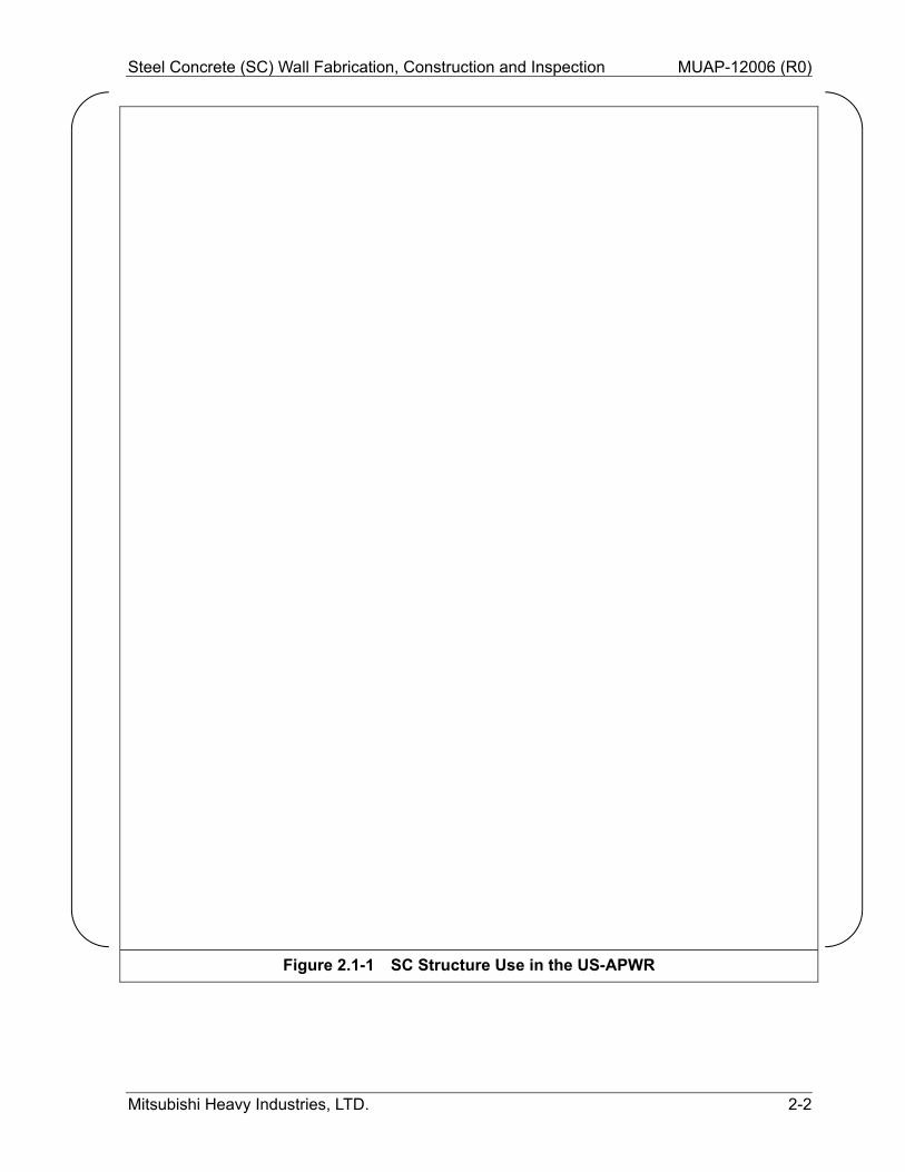
SC structures are used for walls of the US-APWR CIS. Typical applications are for major wall segments such as:
The primary shield wall which surrounds the reactor vessel The secondary shield walls surrounding the primary loops from the steam generator
compartments The steam generator compartment walls The pressurizer compartment walls The refueling cavity walls The refueling water storage pit (RWSP) walls
Figure 2.1-1 shows examples of SC structure use in the US-APWR.
The SC walls are separated into three categories, as follows:
Steel Concrete (SC) Wall Fabrication, Construction and Inspection MUAP-12006 (R0)
Mitsubishi Heavy Industries, LTD. 2-2
Figure 2.1-1 SC Structure Use in the US-APWR
Steel Concrete (SC) Wall Fabrication, Construction and Inspection MUAP-12006 (R0)
Mitsubishi Heavy Industries, LTD. 2-3
2.2 Applicable Codes and Standards
Construction of SC structures shall comply with ACI 349 and ANSI/AISC N690. Construction of the SC structure steel base plate, which is a part of PCCV liner plate, and attachments to the steel base plate shall comply with ASME Section III, Division 2. (1) American Concrete Institute (ACI)
ACI 349-06, Code Requirements for Nuclear Safety-Related Concrete Structures
ACI 117-10, Specification for Tolerances for Concrete Construction and Materials
ACI 304R-00, Guide for Measuring, Mixing, Transporting, and Placing Concrete (Reapproved 2009)
ACI 311.4R-05, Guide for Concrete Inspection
ACI 311.5-04, Guide for Concrete Plant Inspection and Testing of Ready-Mixed Concrete
ACI 347-04, Guide to Formwork for Concrete
ACI 207.1R-05, Guide to Mass Concrete (Reapproved 2012)
ACI 237R-07, Self-Consolidating Concrete
(2) American National Standards Institute/American Institute of Steel Construction(ANSI/AISC)
ANSI/AISC N690-1994, Specification for the Design, Fabrication and Erection of Steel Safety-Related Structures for Nuclear Facilities, Including Supplement 2 (2004), American National Standards Institute/American Institute of Steel Construction, 1994 & 2004
(3) American Society of Mechanical Engineers (ASME)
ASME Section III, Division 2, Subsection CC, Concrete Containments (Prestressed or Reinforced), American Society of Mechanical Engineers, 2001 Edition through the 2003 Addenda
ASME NQA-1-1994, Quality Assurance Requirements for Nuclear Power Plants
ASME Section II, SA-516 Pressure Vessel Plates, Carbon Steel, for Moderate- and Lower-Temperature Service, 2001 Edition through the 2003 Addenda
ASME Section IX Welding and Brazing Qualifications, 2001 Edition through the 2003 Addenda
ASME Section XI, Rules for Inservice Inspection of Nuclear Power Plant Components, 2001 Edition through the 2003 Addenda
(4) American Welding Society (AWS)
AWS D1.1 Structural Welding Code - Steel, D1.1, American Welding Society, 2006.
AWS D1.6 Structural Welding Code - Stainless Steel, D1.6, American Welding Society, 1999
(5) American Society for Testing and Materials (ASTM)
ASTM A572-00a, Standard Specification for High-Strength, Low-Alloy Columbium-Vanadium Structural Steel
Steel Concrete (SC) Wall Fabrication, Construction and Inspection MUAP-12006 (R0)
Mitsubishi Heavy Industries, LTD. 2-4
ASTM A108-07, Standard Specification for Steel Bar, Carbon and Alloy, Cold-Finished
ASTM A240-04, Standard Specification for Chromium-Nickel Stainless Steel Plate, Sheet and Strip for Pressure Vessel and for General Applications
ASTM A264-03, Standard Specification for Stainless Chromium-Nickel Steel-Clad Plate
ASTM A513-90, Standard Specification for Electric-Resistance-Welded Carbon and Alloy Steel Mechanical Tubing
ASTM A615-04b, Standard Specification for Deformed and Plain Carbon-Steel Bars for Concrete Reinforcement
ASTM A706-04b, Standard Specification for Low-Alloy Steel Deformed and Plain Bars for Concrete Reinforcement
(6) 10 CFR 50 Appendix B, Quality Assurance Criteria for Nuclear Power Plants and Fuel
Reprocessing Plants
(7) NUREG/CR-6486, Assessment of Modular Construction for Safety-Related Structures at
Advanced Nuclear Power Plants
Steel Concrete (SC) Wall Fabrication, Construction and Inspection MUAP-12006 (R0)
Mitsubishi Heavy Industries, LTD. 2-5
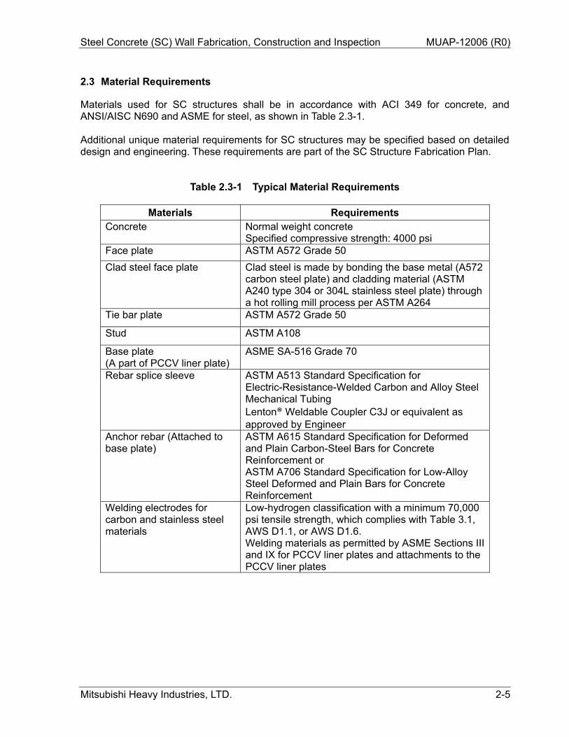
2.3 Material Requirements
Materials used for SC structures shall be in accordance with ACI 349 for concrete, and ANSI/AISC N690 and ASME for steel, as shown in Table 2.3-1. Additional unique material requirements for SC structures may be specified based on detailed design and engineering. These requirements are part of the SC Structure Fabrication Plan.
Table 2.3-1 Typical Material Requirements
Materials Requirements Concrete Normal weight concrete
Specified compressive strength: 4000 psi Face plate ASTM A572 Grade 50
Clad steel face plate Clad steel is made by bonding the base metal (A572 carbon steel plate) and cladding material (ASTM A240 type 304 or 304L stainless steel plate) through a hot rolling mill process per ASTM A264
Tie bar plate ASTM A572 Grade 50
Stud ASTM A108
Base plate (A part of PCCV liner plate)
ASME SA-516 Grade 70
Rebar splice sleeve ASTM A513 Standard Specification for Electric-Resistance-Welded Carbon and Alloy Steel Mechanical Tubing Lenton® Weldable Coupler C3J or equivalent as approved by Engineer
Anchor rebar (Attached to base plate)
ASTM A615 Standard Specification for Deformed and Plain Carbon-Steel Bars for Concrete Reinforcement or ASTM A706 Standard Specification for Low-Alloy Steel Deformed and Plain Bars for Concrete Reinforcement
Welding electrodes for carbon and stainless steel materials
Low-hydrogen classification with a minimum 70,000 psi tensile strength, which complies with Table 3.1, AWS D1.1, or AWS D1.6. Welding materials as permitted by ASME Sections III and IX for PCCV liner plates and attachments to the PCCV liner plates
Steel Concrete (SC) Wall Fabrication, Construction and Inspection MUAP-12006 (R0)
Mitsubishi Heavy Industries, LTD. 3-1
3.0 FABRICATION AND CONSTRUCTION PROCEDURES
Typically, the steel portion of SC structures is pre-fabricated as modules in a shop and shipped to the construction site. At the site, SC structure steel modules are placed and joined as necessary. After erection of the SC modules, concrete is poured into the inside of the SC modules. The face plates act as formwork in placing concrete. The final fabrication and construction requirements and sequences for the SC structure steel and concrete are specified in the SC Structure Fabrication Plan and SC Structure Construction Plan which is developed as part of detailed design and construction planning.
3.1 Shop Fabrication
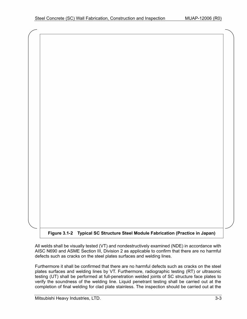
Shop fabrication of SC structure steel modules shall be in accordance with ANSI/AISC N690 (Section Q1.23, FABRICATION, and Section Q1.17, WELDS) and ASME Section III, Division 2 (Article CC-4000 FABRICATION AND CONSTRUCTION) for base plate of SC structure. The SC modules are fabricated based on following basic concept activities and sequences. Figure 3.1-1 and Figure 3.1-2 show the typical fabrication process. As can be seen in Figure 3.1-1, inspection and examination occurs throughout the fabrication process.
a. Layout the requisite patterns on steel plates b. Cutting, grooving, drilling c. Welding face plates d. Welding of studs and tie bars e. Installation of penetration sleeves and attachments, etc. f. SC modules assembly
Ste
el C
oncr
ete
(SC
) W
all
Fab
ricat
ion,
Con
stru
ctio
n an
d In
spec
tion
MU
AP
-120
06 (
R0)
Mits
ubis
hi H
eavy
Indu
strie
s, L
TD
.
3-
2
Fig
ure
3.1
-1
Typ
ical
Fab
rica
tio
n S
equ
ence
of
a S
C S
tru
ctu
re M
od
ule
Steel Concrete (SC) Wall Fabrication, Construction and Inspection MUAP-12006 (R0)
Mitsubishi Heavy Industries, LTD. 3-3
Figure 3.1-2 Typical SC Structure Steel Module Fabrication (Practice in Japan)
All welds shall be visually tested (VT) and nondestructively examined (NDE) in accordance with AISC N690 and ASME Section III, Division 2 as applicable to confirm that there are no harmful defects such as cracks on the steel plates surfaces and welding lines. Furthermore it shall be confirmed that there are no harmful defects such as cracks on the steel plates surfaces and welding lines by VT. Furthermore, radiographic testing (RT) or ultrasonic testing (UT) shall be performed at full-penetration welded joints of SC structure face plates to verify the soundness of the welding line. Liquid penetrant testing shall be carried out at the completion of final welding for clad plate stainless. The inspection should be carried out at the
Steel Concrete (SC) Wall Fabrication, Construction and Inspection MUAP-12006 (R0)
Mitsubishi Heavy Industries, LTD. 3-4
fabrication shop. When modules are joined at the construction site, the same inspections should be performed. The welded configurations not suitable for UT or RT shall be identified in the SC Structure Fabrication Plan and alternate NDE techniques established. In addition to above, NDE must also be specified for:
Welds at SC structure wall connection to basemat base plate Rebar splice sleeve welds
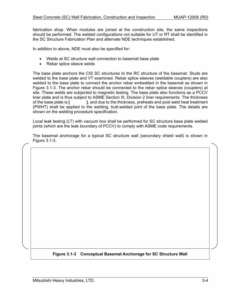
The base plate anchors the CIS SC structures to the RC structure of the basemat. Studs are welded to the base plate and VT examined. Rebar splice sleeves (weldable couplers) are also welded to the base plate to connect the anchor rebar embedded in the basemat as shown in Figure 3.1-3. The anchor rebar should be connected to the rebar splice sleeves (couplers) at site. These welds are subjected to magnetic testing. The base plate also functions as a PCCV liner plate and is thus subject to ASME Section III, Division 2 liner requirements. The thickness of the base plate is [ ], and due to the thickness, preheats and post weld heat treatment (PWHT) shall be applied to the welding, butt-welded joint of the base plate. The details are shown on the welding procedure specification. Local leak testing (LT) with vacuum box shall be performed for SC structure base plate welded joints (which are the leak boundary of PCCV) to comply with ASME code requirements.
The basemat anchorage for a typical SC structure wall (secondary shield wall) is shown in Figure 3.1-3.
Figure 3.1-3 Conceptual Basemat Anchorage for SC Structure Wall
Steel Concrete (SC) Wall Fabrication, Construction and Inspection MUAP-12006 (R0)
Mitsubishi Heavy Industries, LTD. 3-5
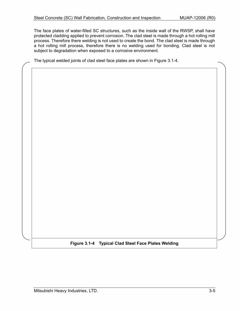
The face plates of water-filled SC structures, such as the inside wall of the RWSP, shall have protected cladding applied to prevent corrosion. The clad steel is made through a hot rolling mill process. Therefore there welding is not used to create the bond. The clad steel is made through a hot rolling mill process, therefore there is no welding used for bonding. Clad steel is not subject to degradation when exposed to a corrosive environment. The typical welded joints of clad steel face plates are shown in Figure 3.1-4.
Figure 3.1-4 Typical Clad Steel Face Plates Welding
Steel Concrete (SC) Wall Fabrication, Construction and Inspection MUAP-12006 (R0)
Mitsubishi Heavy Industries, LTD. 3-6
Fabrication tolerances shall be based on the requirements of ACI 117 Section 4, CAST-IN-PLACE CONCRETE FOR BUILDINGS, and ANSI/AISC N690 Q1.23.11, TOLERANCES, as applicable including the following requirements;
The thickness of the SC structure wall complies with the biological shield wall requirements, i.e. the minus side tolerance for thickness tolerances of the shield walls are limited.
The tolerances required for components installation shall be met. The fabricated SC structure steel module has sufficient length or width to adjust and
meets the final erection tolerances. The specific fabrication details, welding requirements and tolerances are defined in the SC Structure Fabrication Plan. Inspection details are contained in the SC Structure Inspection Plan. These documents are created as part of detailed design. In addition to normal fabrication tolerances such as length and width of steel components; tolerances for SC structures must also be specified for:
Dimension of SC structure steel modules (width, length and height) Dimensions of studs (length, spacing and alignment) Dimensions of tie bars (length, spacing and alignment) Distances between the face plates and the flatness of face plates Location of penetrations, attachments and component supports Location of weldable couplers under the base plate Welding joint dimension
These tolerances shall be specified in the SC Structure Fabrication Plan and shown on the design drawings used by the fabricator. After fabrication at the shop, protective coatings as required are applied on exposed steel surfaces. Protective coatings that become part of the final installed SC structure shall be applied in accordance with approved procedures for “inside containment” service.
Steel Concrete (SC) Wall Fabrication, Construction and Inspection MUAP-12006 (R0)
Mitsubishi Heavy Industries, LTD. 3-7
3.2 Handling and Shipping
Handling, packing and shipping of SC structure steel modules shall be in accordance with ANSI/AISC N690 (Section Q1.28, PACKING, SHIPPING, RECEIVING, STORAGE, AND HANDLING) and Basic Requirement 13 and Supplement 13S-1 of ASME NQA-1. The SC structure modules are shipped via rail, truck or barge/ship, depending on the fabrication shop location and site access restrictions. The SC structure module sizes are designed based on the available access to the site. An example of the SC module in shipment is shown in Figure 3.2-1:
Figure 3.2-1 Shipping of SC Module Structure Steel (Typical Practice in Japan)
After fabrication of the SC modules, the modules are shipped to the construction site. Necessary precautions, such as wiring, shipping jig installation, transport speed, etc. should be considered to avoid damage to SC structure during handling and shipment. The center of gravity and assembly weight for heavy modules should be clearly identified for shipping. The hoist points required for handling and shipping should be designed, fabricated, and placed on the SC modules. The SC modules shall be subject to a detailed release inspection at point of shipment. Shipping precautions shall be established prior to release for shipping. The SC modules shall be again inspected at receipt. Note that if SC modules are transported by ocean-going ship, additionally cleaning methods to remove sea salt should be established. The final handling and shipping requirements are specified in a site specific SC Steel Transport Plan.
Steel Concrete (SC) Wall Fabrication, Construction and Inspection MUAP-12006 (R0)
Mitsubishi Heavy Industries, LTD. 3-8
3.3 Storage
Storage of SC structure steel modules shall be in accordance with ANSI/AISC N690 (Section Q1.28, PACKING, SHIPPING, RECEIVING, STORAGE, AND HANDLING) and Basic Requirement 13 and Supplement 13S-1 of ASME NQA-1. The SC modules are kept in a temporary storage area at the construction site in preparation of the installation sequence.
3.4 Erection
Erection of SC structure steel modules shall be in accordance with ANSI/AISC N690 (Section Q1.25, ERECTION) and ASME Section III, Division 2 (Article CC-4000 FABRICATION AND CONSTRUCTION) for base plate. The SC modules are delivered to the site in shippable sub-assemblies. These sub-assemblies may be further assembled in temporary fabrication facilities or storage areas on site as necessary, into larger modules. The SC structures are transported to the crane for installation. The SC modules installation typically starts with the lower sections and proceeds to the upper sections. During the installation process and at the completion of an SC structure, measurements are made to verify the accuracy for the position and orientation. The installation tolerance values are determined based on the ACI code requirements for RC structures. If the mechanical and electrical systems require tighter tolerance values, those system requirements take precedence over concrete tolerances. The welding codes and procedures at the construction site are specified based on those of the fabrication shop. The SC structure base plate, the leak boundary of PCCV, is welded with preheat and PWHT and LT in accordance with the requirements of ASME code. Where the PCCV base liner plate mates with the base plate, it is connected to the base plate by butt-welding and LT shall be conducted. The SC modules meet the requirements of concrete formwork which should be the similar requirement of RC structures in accordance with ACI 347 and ACI 117 so that the final SC structure satisfies the equivalent tolerances of RC structure, and ANSI/AISC N690. The SC Structure Construction Plan specifies the construction loads, lateral pressure of concrete, and other conditions such as rate of placement and temperature. Except as specified, the stress due to the lateral pressure of concrete is checked. For the assembly and joining of SC modules, tolerances must be specified for:
Horizontal and vertical spacing between SC structure steel plates Vertical alignment of SC structure steel modules Dimensions (width, length and height) of SC structure steel modules after installation Welding joint dimension Location of tie bars, studs, penetrations, attachments, and component supports after
installation, as required These tolerances shall be specified in the SC Structure Construction Plan.
Steel Concrete (SC) Wall Fabrication, Construction and Inspection MUAP-12006 (R0)
Mitsubishi Heavy Industries, LTD. 3-9
For erection of the SC modules and final assemblies, the center of gravity shall be clearly identified for installation. The hoist points required for erection at site should be designed, fabricated, and placed on the SC modules to prevent distortion. During and/or after erection of SC modules, coatings are applied on steel surfaces as required. The coating locations and procedures are specified in the SC Structure Construction Plan. A typical erection sequence for SC modules is shown in Figure 3.4-1. The concept of installation sequence and anchorage of the SC structure to basemat are shown in Figure 3.4-2.
Ste
el C
oncr
etes
(S
C)
Wal
l Fab
ricat
ion,
Con
stru
ctio
n an
d In
spec
tion
MU
AP
-120
06 (
R0)
Mits
ubis
hi H
eavy
Indu
strie
s, L
TD
. 3-
10
Fig
ure
3.4
-1
Typ
ical
Ere
ctio
n S
eq
uen
ce o
f S
C S
tru
ctu
re S
teel
Mo
du
les
(Sh
eet
1 o
f 2)
Ste
el C
oncr
etes
(S
C)
Wal
l Fab
ricat
ion,
Con
stru
ctio
n an
d In
spec
tion
MU
AP
-120
06 (
R0)
Mits
ubis
hi H
eavy
Indu
strie
s, L
TD
. 3-
11
Fig
ure
3.4
-1
Typ
ical
Ere
ctio
n S
eq
uen
ce o
f S
C S
tru
ctu
re S
teel
Mo
du
les
(Sh
eet
2 o
f 2)
Ste
el C
oncr
etes
(S
C)
Wal
l Fab
ricat
ion,
Con
stru
ctio
n an
d In
spec
tion
MU
AP
-120
06 (
R0)
Mits
ubis
hi H
eavy
Indu
strie
s, L
TD
. 3-
12
Fig
ure
3.4
-2
Typ
ical
SC
Str
uct
ure
An
cho
rag
e to
Bas
emat
Steel Concrete (SC) Wall Fabrication, Construction and Inspection MUAP-12006 (R0)
Mitsubishi Heavy Industries, LTD. 3-13
Overview photos of SC structure steel module construction of an actual plant are shown in Figure 3.4-3 as a reference.
Figure 3.4-3 Overview of SC Structure Steel Module Construction (Practice in Japan)
Steel Concrete (SC) Wall Fabrication, Construction and Inspection MUAP-12006 (R0)
Mitsubishi Heavy Industries, LTD. 3-14
3.5 Concrete Placement
Concrete mix and placement are specified in the SC Structure Construction Plan which is developed as part of construction planning. 3.5.1 Concrete Mixing
Concrete mix plan shall be in accordance with ACI 304R-00 (Guide for Measuring, Mixing, Transporting, and Placing Concrete (Reapproved 2009)) and ACI 311.4R (Guide for Concrete Inspection). Normal weight concrete should be placed in the SC structure wall. The quality of the concrete should meet the performance requirements for the concrete (workability, compressive strength, dry weight per unit volume, etc.) which is established in the SC Structure Construction Plan.
3.5.1.1 Concrete Mix Plan
Prior to concrete work, mix design should be performed in accordance with ACI 304R-00 (Guide for Measuring, Mixing, Transporting, and Placing Concrete (Reapproved 2009)). After confirming that the required concrete performance has been achieved, concrete mix proportion setting should be performed unless otherwise specified. Of the target properties of the concrete, the specified compressive strength of concrete shall be 4000 psi. Concrete compressive strength test age should be decided in design phase and included in the construction plan. The following concrete properties should be specified for the concrete mix.
- Dry weight per unit volume - Salt content - Maximum water-cement ratio - Slump - Air content - Aggregate size
3.5.1.2 Control and Change of the Concrete Mix Proportion
Verification of concrete materials and mixed concrete should be performed in accordance with ACI 311.4R (Guide for Concrete Inspection) to ensure that the concrete meets the design performance requirements.
If any change has been identified in the quality of the materials used in the concrete or if the required performance for the concrete to be used is not achieved, the mix proportion should be adjusted or changed as needed. 3.5.1.3 Grout Mix Plan
The compressive strength of grout shall not be less than 4,000 psi, the same as the concrete strength. A zero shrinkage type of grout shall be used.
Steel Concrete (SC) Wall Fabrication, Construction and Inspection MUAP-12006 (R0)
Mitsubishi Heavy Industries, LTD. 3-15
3.5.2 Production of Concrete
Production of concrete shall be in accordance with ACI 304R-00 (Guide for Measuring, Mixing, Transporting, and Placing Concrete (Reapproved 2009)), ACI 311.4R (Guide for Concrete Inspection) and ACI 237R-07 (Self-Consolidating Concrete). 3.5.2.1 Specifications for the Concrete Plant
The concrete batch plant generates concrete which meets specification. However, the transport time of the concrete should be monitored to ensure that the concrete maintains specification. 3.5.2.2 Production of Concrete
When determining the method for mixing concrete, trial mixes should be performed in the production plant prior to actual production to ensure that a uniform mix is produced. To efficiently produce uniform concrete, the procedures for feeding materials into the mixer and the mixing time are developed and determined in advance.
3.5.2.3 Production of Flowing Concrete
In installations where there is a concern for rate of concrete flow, plasticizers may be used to improve fluidity of the concrete. The plasticizer should be tested through a trial mix.
Plasticizer can be used in the following ways. The timing of adding the plasticizer and the mixing method should be pre-determined so that the required plasticity can be obtained. Possible methods for adding the plasticizer include:
Add and mix the plasticizer at the unloading location.
Add the plasticizer in the concrete plant and mix it into the concrete at the unloading location.
Add the plasticizer in the concrete plant and mix it into the concrete.
The methodology is prescribed in the site specific SC Structure Construction Plan.
Steel Concrete (SC) Wall Fabrication, Construction and Inspection MUAP-12006 (R0)
Mitsubishi Heavy Industries, LTD. 3-16
3.5.2.4 Production of Self-Consolidating Concrete
Self-consolidating concrete (SCC) improves the fluidity without spoiling segregation resistance, and SCC can be placed without vibration and consolidation. Therefore, SCC is used for placing concrete in pour regions where consolidation is difficult such as under the base plate or the steel plate at the top of the SC structure wall. (For production and placement of SCC, refer to ACI 237R “Self-Consolidating Concrete”).
The production of SCC involves many materials, making it complex to weigh the materials, feed them into the mixer and mix them compared to the production of normal concrete. Continuous production is desirable for a stable supply of SCC with the required plasticity and stability (segregation resistance). The production of SCC should not be interrupted by alternate delivery of different types of concretes. If SCC using a segregation-controlling agent is left in the mixer, the other type of concrete to be mixed is affected. Therefore, when the production is switched from SCC to normal concrete, the mixer should be cleaned so that the new mix has the proper proportions.
3.5.2.5 Control and Inspection of Production Equipment
The inspection of the concrete production equipment should be performed in accordance with ACI 311.5 (Guide for Concrete Plant Inspection and Testing of Ready-Mixed Concrete) to ensure that the equipment can achieve the quality specified for the production of concrete.
3.5.3 Transportation of Concrete
Transportation of concrete should be in accordance with ACI 304R-00 (Guide for Measuring, Mixing, Transporting, and Placing Concrete (Reapproved 2009)). The preparation for concrete transportation follows a prescribed concrete placement plan prior to concrete placement. 3.5.4 Concrete Placement
Concrete placement for SC structures shall be in accordance with ACI 304R-00 (Guide for Measuring, Mixing, Transporting, and Placing Concrete (Reapproved 2009)), ACI 347-04 (Guide to Formwork for Concrete), ACI 207.1R-05 (Guide to Mass Concrete (Reapproved 2012)) and ACI 237R-07 (Self-Consolidating Concrete). Construction tolerances shall be based on the requirements of ACI 117 Section 4, CAST-IN-PLACE CONCRETE FOR BUILDINGS, as applicable. 3.5.4.1 Overall Process
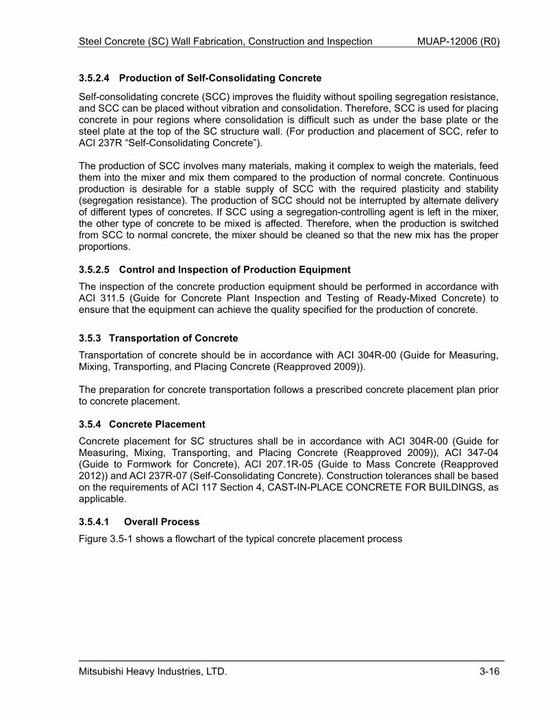
Figure 3.5-1 shows a flowchart of the typical concrete placement process
Steel Concrete (SC) Wall Fabrication, Construction and Inspection MUAP-12006 (R0)
Mitsubishi Heavy Industries, LTD. 3-17
Figure 3.5-1 Flow Chart for Concrete Placement
3.5.4.2 Preparation for concrete placement
The preparation for concrete placement follows a prescribed concrete placement plan and foreign material exclusion plan prior to concrete placement. 3.5.4.3 Concrete Placement
3.5.4.3.1 Standard Practice
Concrete should be pumped into the SC structure wall through the concrete pipeline using a concrete pump source. Concrete placement should start at the point farthest from the pump source using a boom or a separately installed concrete pipeline. When the concrete is placed using a concrete pipeline, the piping which is furthest away from the concrete pump should be removed as placement gets closer to the concrete pump source. When placing on consolidated fresh concrete, concrete should be placed horizontally to prevent excessive lateral pressure from being applied to both the face and web plates of the SC structure wall as shown in Figure 3.5-2. [
] The next concrete layer should be placed to avoid aggregates not filling under the tie bars, as shown in Figure 3.5-3.
Steel Concrete (SC) Wall Fabrication, Construction and Inspection MUAP-12006 (R0)
Mitsubishi Heavy Industries, LTD. 3-18
Figure 3.5-2 Horizontal Concrete Placement (Example)
Figure 3.5-3 Example of Placement of Fresh Concrete on Hardened Concrete
Steel Concrete (SC) Wall Fabrication, Construction and Inspection MUAP-12006 (R0)
Mitsubishi Heavy Industries, LTD. 3-19
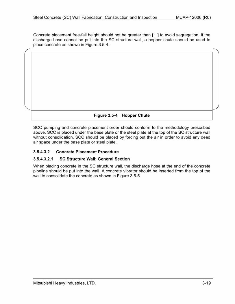
Concrete placement free-fall height should not be greater than [ ] to avoid segregation. If the discharge hose cannot be put into the SC structure wall, a hopper chute should be used to place concrete as shown in Figure 3.5-4.
Figure 3.5-4 Hopper Chute
SCC pumping and concrete placement order should conform to the methodology prescribed above. SCC is placed under the base plate or the steel plate at the top of the SC structure wall without consolidation. SCC should be placed by forcing out the air in order to avoid any dead air space under the base plate or steel plate. 3.5.4.3.2 Concrete Placement Procedure
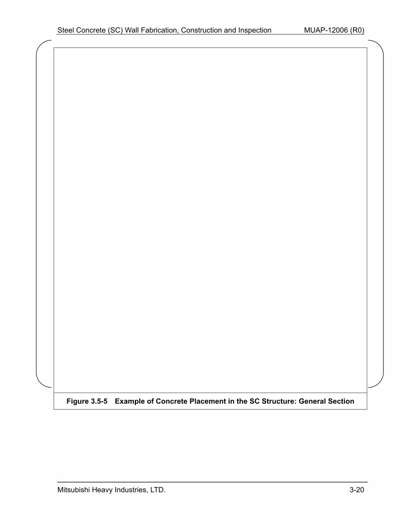
3.5.4.3.2.1 SC Structure Wall: General Section
When placing concrete in the SC structure wall, the discharge hose at the end of the concrete pipeline should be put into the wall. A concrete vibrator should be inserted from the top of the wall to consolidate the concrete as shown in Figure 3.5-5.
Steel Concrete (SC) Wall Fabrication, Construction and Inspection MUAP-12006 (R0)
Mitsubishi Heavy Industries, LTD. 3-20
Figure 3.5-5 Example of Concrete Placement in the SC Structure: General Section
Steel Concrete (SC) Wall Fabrication, Construction and Inspection MUAP-12006 (R0)
Mitsubishi Heavy Industries, LTD. 3-21
3.5.4.3.2.2 SC Structure Wall: Underside of the Base Plate
SCC should be placed under the base plate without vibration and consolidation. To avoid any dead air space under the base plate, the concrete placement should be poured in one direction to allow air to vent though opposite side. In addition, concrete may be pumped under pressure to fill voids. 3.5.4.3.3 Concrete Placement Procedure Taking Concrete Lateral Pressure into
Account
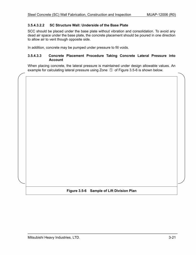
When placing concrete, the lateral pressure is maintained under design allowable values. An example for calculating lateral pressure using Zone ① of Figure 3.5-6 is shown below.
Figure 3.5-6 Sample of Lift Division Plan
Steel Concrete (SC) Wall Fabrication, Construction and Inspection MUAP-12006 (R0)
Mitsubishi Heavy Industries, LTD. 3-22
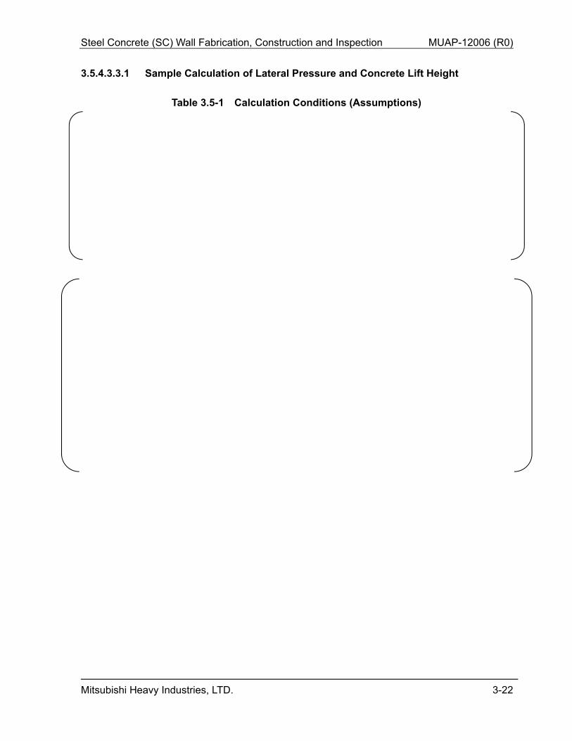
3.5.4.3.3.1 Sample Calculation of Lateral Pressure and Concrete Lift Height
Table 3.5-1 Calculation Conditions (Assumptions)
Steel Concrete (SC) Wall Fabrication, Construction and Inspection MUAP-12006 (R0)
Mitsubishi Heavy Industries, LTD. 3-23
Steel Concrete (SC) Wall Fabrication, Construction and Inspection MUAP-12006 (R0)
Mitsubishi Heavy Industries, LTD. 3-24
Table 3.5-2 Excerpts from ACI 347 (Sheet 1 of 2)
Steel Concrete (SC) Wall Fabrication, Construction and Inspection MUAP-12006 (R0)
Mitsubishi Heavy Industries, LTD. 3-25
Table 3.5-2 Excerpts from ACI 347 (Sheet 2 of 2)
Steel Concrete (SC) Wall Fabrication, Construction and Inspection MUAP-12006 (R0)
Mitsubishi Heavy Industries, LTD. 3-26
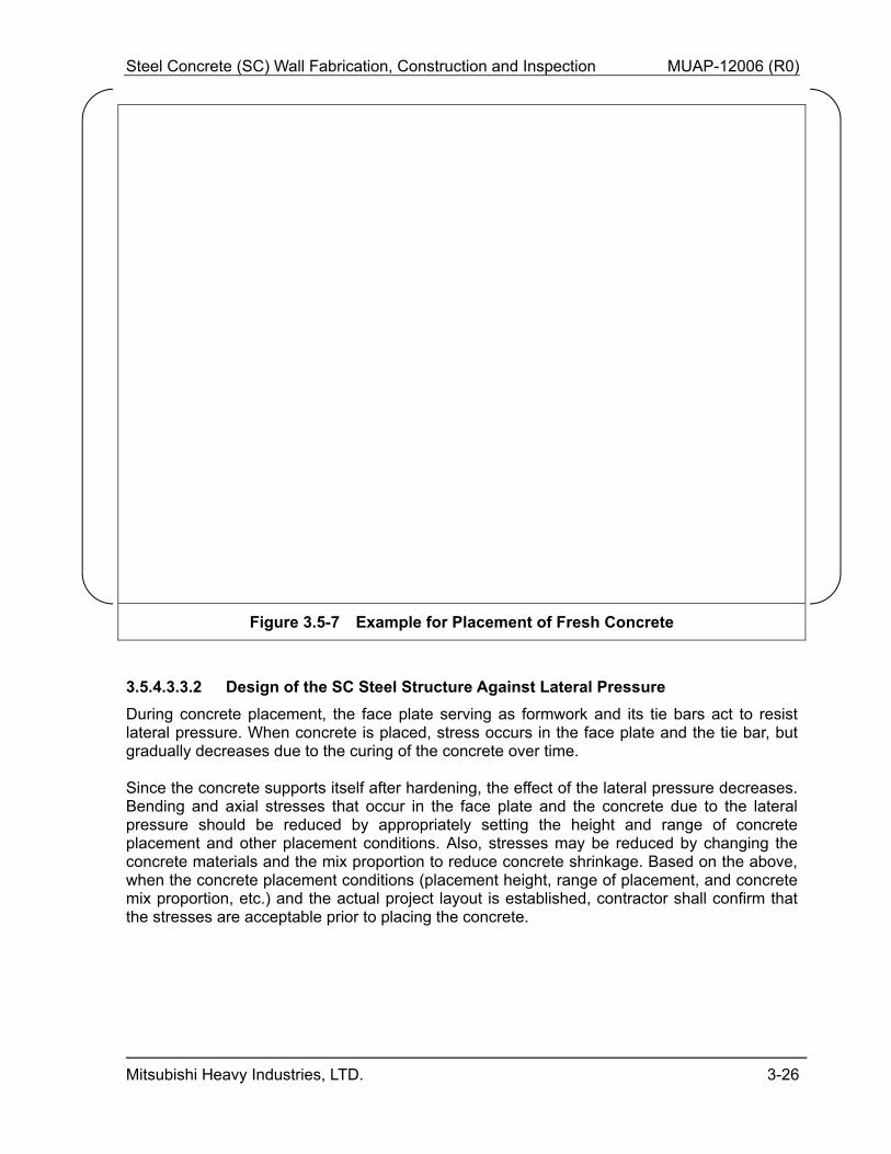
Figure 3.5-7 Example for Placement of Fresh Concrete
3.5.4.3.3.2 Design of the SC Steel Structure Against Lateral Pressure
During concrete placement, the face plate serving as formwork and its tie bars act to resist lateral pressure. When concrete is placed, stress occurs in the face plate and the tie bar, but gradually decreases due to the curing of the concrete over time. Since the concrete supports itself after hardening, the effect of the lateral pressure decreases. Bending and axial stresses that occur in the face plate and the concrete due to the lateral pressure should be reduced by appropriately setting the height and range of concrete placement and other placement conditions. Also, stresses may be reduced by changing the concrete materials and the mix proportion to reduce concrete shrinkage. Based on the above, when the concrete placement conditions (placement height, range of placement, and concrete mix proportion, etc.) and the actual project layout is established, contractor shall confirm that the stresses are acceptable prior to placing the concrete.
Steel Concrete (SC) Wall Fabrication, Construction and Inspection MUAP-12006 (R0)
Mitsubishi Heavy Industries, LTD. 3-27
3.5.4.3.4 Consolidation
The concrete is typically consolidated with 2-1/2″ diameter rod-type concrete vibrators. A 1-3/4″ diameter concrete vibrator can be used for narrow spaces. The concrete vibrator shall be used in each concrete placement. A vibrator shall be inserted into the previously placed layer to ensure good bonding. The concrete vibrator should be inserted at a spacing of [ ] that allows overlapping of effective consolidation areas. The concrete vibrator should be used for about [ ] in each location or until the mortar paste comes up to surface. 3.5.4.3.5 Ensuring the SC Structure Filled with Concrete
The following sections describe the methods for ensuring the SC Structures are completely filled with concrete and describes methods for dealing with configurations where void formation is possible.
3.5.4.3.5.1 Typical Section
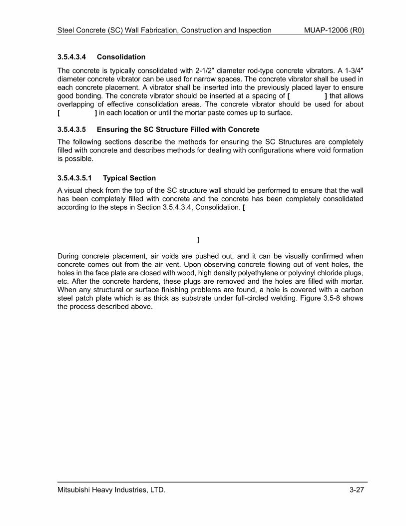
A visual check from the top of the SC structure wall should be performed to ensure that the wall has been completely filled with concrete and the concrete has been completely consolidated according to the steps in Section 3.5.4.3.4, Consolidation. [
] During concrete placement, air voids are pushed out, and it can be visually confirmed when concrete comes out from the air vent. Upon observing concrete flowing out of vent holes, the holes in the face plate are closed with wood, high density polyethylene or polyvinyl chloride plugs, etc. After the concrete hardens, these plugs are removed and the holes are filled with mortar. When any structural or surface finishing problems are found, a hole is covered with a carbon steel patch plate which is as thick as substrate under full-circled welding. Figure 3.5-8 shows the process described above.
Steel Concrete (SC) Wall Fabrication, Construction and Inspection MUAP-12006 (R0)
Mitsubishi Heavy Industries, LTD. 3-28
Figure 3.5-8 Checking Concrete Placement in Typical SC Structure Wall
Steel Concrete (SC) Wall Fabrication, Construction and Inspection MUAP-12006 (R0)
Mitsubishi Heavy Industries, LTD. 3-29
3.5.4.3.5.2 Horizontal Structural Member Section at the Intermediate SC Structure Wall
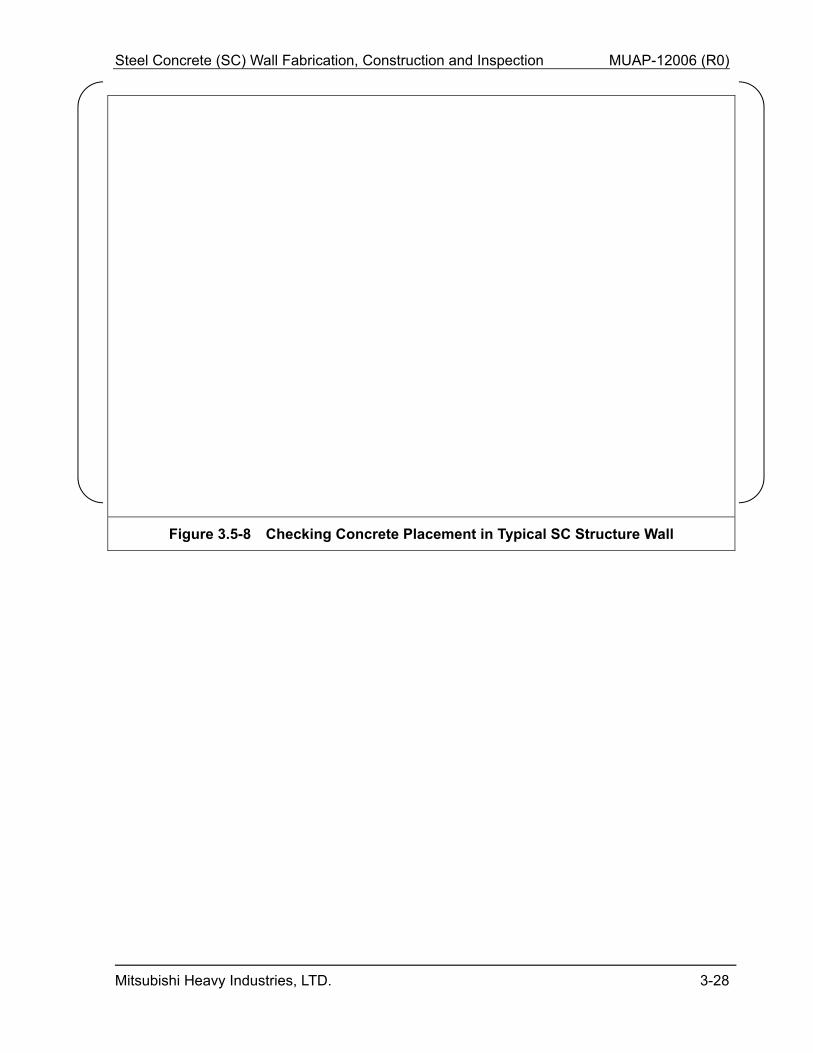
If horizontal structural members are inside of an SC structure steel modules (e.g., a stiffener to maintain SC structure modules during transportation), air vent holes should be placed in the horizontal structural member. The vent hole is used to vent air and confirm that concrete is filling the space beneath the horizontal member by ensuring that concrete comes out of the air vent hole holes during placement. If the member is located near the concrete overlay height, concrete is placed up to approximately 8″ below the member. The concrete is left to stand until the top surface of the concrete settles sufficiently. Free water that bleeds to the top surface is absorbed with sponge or a Hydro-Sweeper. After free water is removed, the process of concrete placement proceeds to the next pour elevation or top of SC module, whichever is applicable. Figure 3.5-9 shows the process described above.
Figure 3.5-9 Concept for Placing Concrete in the Area Around a Horizontal Structural Member Section
Steel Concrete (SC) Wall Fabrication, Construction and Inspection MUAP-12006 (R0)
Mitsubishi Heavy Industries, LTD. 3-30
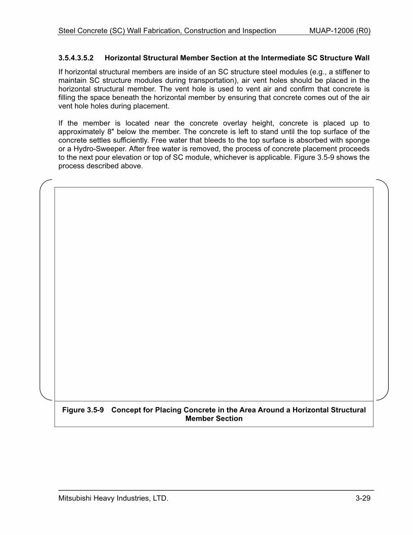
3.5.4.3.5.3 Top of the SC Structure Wall
An approximately 8″ high supplemental formwork is temporarily installed on the top of the SC structure wall to allow concrete under pressure to fill voids under the top plate. Concrete is poured up to the top surface of the formwork to push out the air trapped under the top plate using the head pressure of the concrete inside the formwork. After confirmation that free water has bled to the surface and the top surface of the concrete has sufficiently settled, the temporary formwork and the concrete (in a semi-hardened state) inside the formwork is removed, and the concrete on the top plate is finished. Figure 3.5-10 shows the process described above.
Figure 3.5-10 Concept for Placing Concrete at the Top of the SC Structure Wall
Steel Concrete (SC) Wall Fabrication, Construction and Inspection MUAP-12006 (R0)
Mitsubishi Heavy Industries, LTD. 3-31
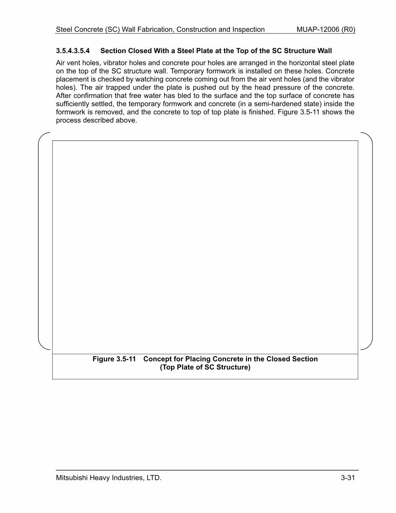
3.5.4.3.5.4 Section Closed With a Steel Plate at the Top of the SC Structure Wall
Air vent holes, vibrator holes and concrete pour holes are arranged in the horizontal steel plate on the top of the SC structure wall. Temporary formwork is installed on these holes. Concrete placement is checked by watching concrete coming out from the air vent holes (and the vibrator holes). The air trapped under the plate is pushed out by the head pressure of the concrete. After confirmation that free water has bled to the surface and the top surface of concrete has sufficiently settled, the temporary formwork and concrete (in a semi-hardened state) inside the formwork is removed, and the concrete to top of top plate is finished. Figure 3.5-11 shows the process described above.
Figure 3.5-11 Concept for Placing Concrete in the Closed Section (Top Plate of SC Structure)
Steel Concrete (SC) Wall Fabrication, Construction and Inspection MUAP-12006 (R0)
Mitsubishi Heavy Industries, LTD. 3-32
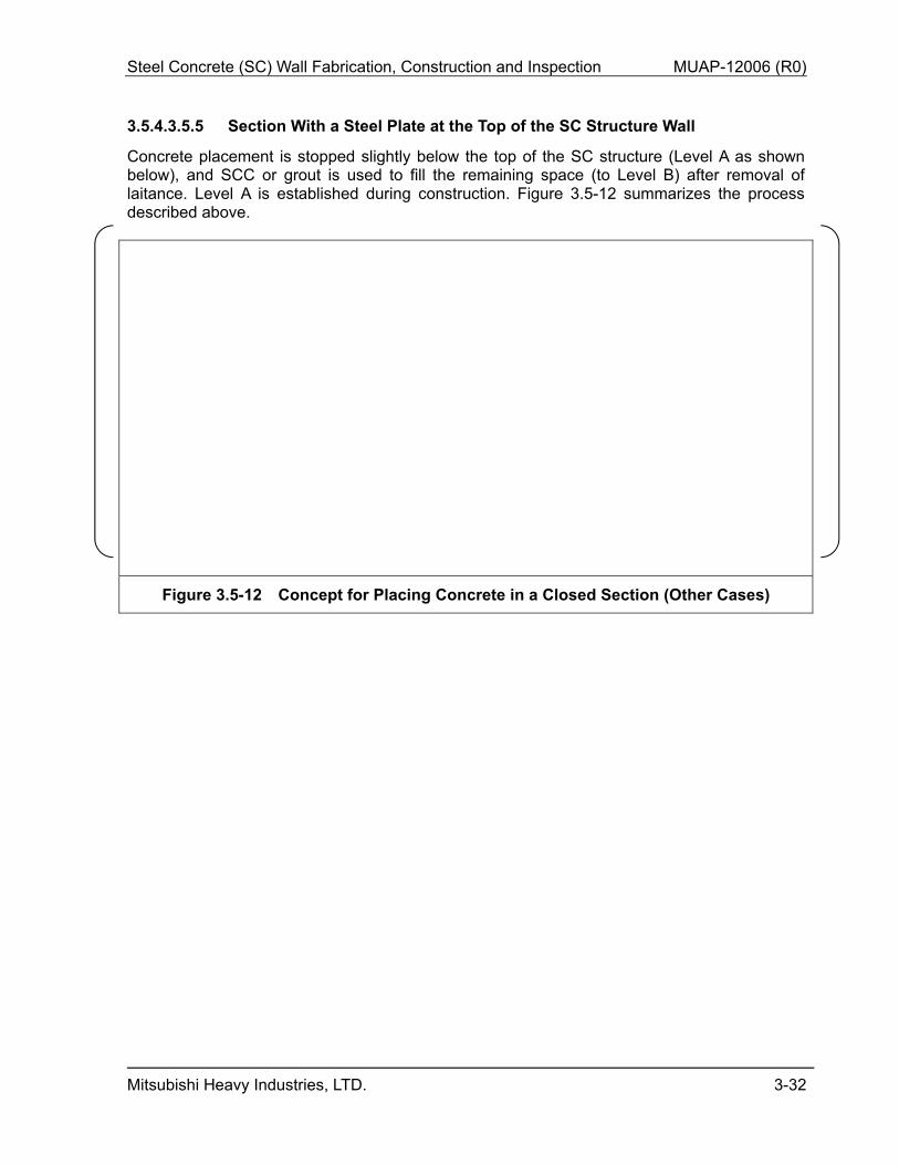
3.5.4.3.5.5 Section With a Steel Plate at the Top of the SC Structure Wall
Concrete placement is stopped slightly below the top of the SC structure (Level A as shown below), and SCC or grout is used to fill the remaining space (to Level B) after removal of laitance. Level A is established during construction. Figure 3.5-12 summarizes the process described above.
Figure 3.5-12 Concept for Placing Concrete in a Closed Section (Other Cases)
Steel Concrete (SC) Wall Fabrication, Construction and Inspection MUAP-12006 (R0)
Mitsubishi Heavy Industries, LTD. 3-33
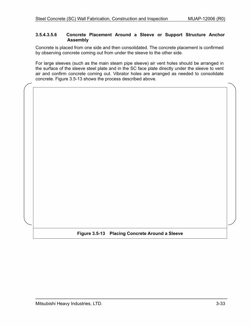
3.5.4.3.5.6 Concrete Placement Around a Sleeve or Support Structure Anchor Assembly
Concrete is placed from one side and then consolidated. The concrete placement is confirmed by observing concrete coming out from under the sleeve to the other side. For large sleeves (such as the main steam pipe sleeve) air vent holes should be arranged in the surface of the sleeve steel plate and in the SC face plate directly under the sleeve to vent air and confirm concrete coming out. Vibrator holes are arranged as needed to consolidate concrete. Figure 3.5-13 shows the process described above.
Figure 3.5-13 Placing Concrete Around a Sleeve
Steel Concrete (SC) Wall Fabrication, Construction and Inspection MUAP-12006 (R0)
Mitsubishi Heavy Industries, LTD. 3-34
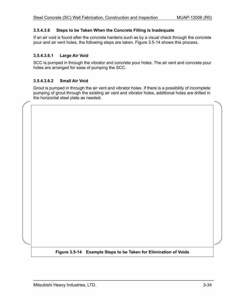
3.5.4.3.6 Steps to be Taken When the Concrete Filling is Inadequate
If an air void is found after the concrete hardens such as by a visual check through the concrete pour and air vent holes, the following steps are taken. Figure 3.5-14 shows this process.
3.5.4.3.6.1 Large Air Void
SCC is pumped in through the vibrator and concrete pour holes. The air vent and concrete pour holes are arranged for ease of pumping the SCC.
3.5.4.3.6.2 Small Air Void
Grout is pumped in through the air vent and vibrator holes. If there is a possibility of incomplete pumping of grout through the existing air vent and vibrator holes, additional holes are drilled in the horizontal steel plate as needed.
Figure 3.5-14 Example Steps to be Taken for Elimination of Voids
Steel Concrete (SC) Wall Fabrication, Construction and Inspection MUAP-12006 (R0)
Mitsubishi Heavy Industries, LTD. 3-35
3.5.4.4 Volume Change of Mass Concrete and Measures to Prevent Shrinkage
Mass concrete volume changes include drying shrinkage, autogenous shrinkage and thermal volume change.
3.5.4.4.1 Drying Shrinkage
Drying shrinkage is deformation resulting from the decrease in the water content in concrete caused by drying. This shrinkage tends to increase with increasing unit cement content, unit water content and water-cement ratio. Therefore, in the detailed mix design stage, the mix proportion is adjusted to minimize these values. In the concrete placement stage, the face plate of the SC structure wall prevents drying of the concrete vertical surface. In addition, the top surface of finished concrete should be cured by spraying water and covering with a mat.
3.5.4.4.2 Autogenous Shrinkage
Autogenous shrinkage is consumed in the concrete mix during the hydration of the cement. After the concrete mix solidifies and will no longer absorb water from an external source, a negative pressure is generated and the concrete shrinks. This shrinkage tends to increase with increasing cement content and decreasing water-cement ratio. During the detailed mix design stage, the mix proportion should be adjusted to an appropriate value to avoid this occurrence.
3.5.4.4.3 Thermal Volume Change
Thermal volume change occurs as follows. As a result of the hydration of the cement paste, hydration heat is generated and accumulated during the initial setting and hardening of the concrete, causing the inside temperature of the concrete to rise and the concrete to expand. Subsequently, as the concrete temperature drops, the concrete shrinks. Due to the rise of the concrete temperature in the initial stage of concrete placement, a non-uniform temperature distribution occurs in the concrete. Due to the subsequent temperature drop, the concrete shrinkage is restrained. As a result, thermal cracking may occur. The following measures to prevent thermal cracking are available in the mix design stage and in the concrete placement stage.
3.5.4.4.3.1 Measures That May be Taken in the Mix Design Stage
In the mix design stage, the temperature rise of concrete should be reduced as much as possible. The following ways are available for this purpose.
Use low heat-generating cement with low hydration heat and slow hydration. Use a concrete mix with reduced unit cement content. Increase the control material age of strength for mix proportion. Reduce the unit water content by adding an admixture or using a concrete mix with a
low slump.
Steel Concrete (SC) Wall Fabrication, Construction and Inspection MUAP-12006 (R0)
Mitsubishi Heavy Industries, LTD. 3-36
3.5.4.4.3.2 Measures That May be Taken in the Concrete Placement Stage
There are two ways available in the concrete placement stage. (1) Reduce the temperature rise of concrete as much as possible.
Pre-cooling the concrete with liquid nitrogen to reduce the concrete temperature during placement.
Replace part of the mixing water with ice flakes. Divide the placement lift. Perform thermal stress analysis to determine the height of concrete to be placed at a
time that prevents thermal cracking. (2) Reduce the temperature difference between the inside and outside of concrete as much as
possible. Slow as much as possible the temperature drop of the concrete after the inside temperature reaches the maximum.
Cover the members with insulation and a sheet to keep them warm.
The thermal cracking mechanism of mass concrete is complex. Therefore, in the detailed mix design and concrete placement planning stages, materials used in the concrete should be selected; the mix proportion and the procedure for concrete placement in the SC structure wall should be determined; thermal stress analysis and evaluation of thermal cracking should be performed; and the combination of measures to prevent thermal cracking should be determined.
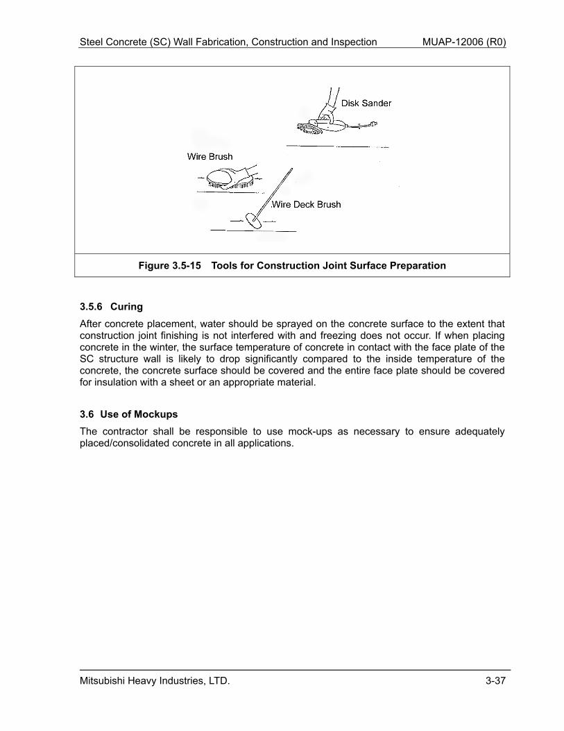
3.5.5 Construction Joint Surface Preparation
Laitance and other weak layers on the surface of the construction joint should be removed with a wire brush or a disc sander until the aggregate surface is exposed. After the construction joint surface preparation, the water used to clean the concrete surface should be collected with a sponge or HYDRO-SWEEPER. As a general rule, no concrete joints should be located in zones not accessible by workers. When it is necessary, after concrete setting, weak layers on the concrete surface should be removed with 6000 psi high-pressure water and the residue should be collected with HYDRO-SWEEPER.
Steel Concrete (SC) Wall Fabrication, Construction and Inspection MUAP-12006 (R0)
Mitsubishi Heavy Industries, LTD. 3-37
Figure 3.5-15 Tools for Construction Joint Surface Preparation
3.5.6 Curing
After concrete placement, water should be sprayed on the concrete surface to the extent that construction joint finishing is not interfered with and freezing does not occur. If when placing concrete in the winter, the surface temperature of concrete in contact with the face plate of the SC structure wall is likely to drop significantly compared to the inside temperature of the concrete, the concrete surface should be covered and the entire face plate should be covered for insulation with a sheet or an appropriate material.
3.6 Use of Mockups
The contractor shall be responsible to use mock-ups as necessary to ensure adequately placed/consolidated concrete in all applications.
Steel Concrete (SC) Wall Fabrication, Construction and Inspection MUAP-12006 (R0)
Mitsubishi Heavy Industries, LTD. 4-1
4.0 INSPECTION/TESTING
Detailed inspection and testing requirement is documented in a SC Structure Inspection Plan which is developed during detailed design based upon information in the SC Structure Fabrication Plan and SC Structure Construction Plan
4.1 SC Structure Steel Modules
Inspection and testing of SC structure steel modules shall be conducted in accordance with ANSI/AISC N690 (Section Q1.26, NONDESTRUCTIVE EXAMINATION, and Section Q1.29, QUALITY CONTROL) and ASME Section III, Division 2 (Article CC-5000, CONSTRUCTION TESTING AND EXAMINATION) for base plate. Inspections, tests, analyses, and acceptance criteria requirements for SC Walls are identified in Design Control Document Tier 1, Section 2.2, ”Structural and Systems Engineering” (as-builts) and Section 2.11, ”Containment Systems” (as-builts and code compliance requirements, structural integrity test/integrated leak rate test).
4.1.1 SC Structure Steel Modules Fabrication
Inspection shall be initiated with the receipt of materials at the fabrication shop. Inspections, including VT of steel plate surfaces shall be performed to confirm that the condition and specifications of materials, such as steel plates, studs, etc., comply with the design documents and drawings. In addition, the Certified Material Test Report shall be reviewed and maintained as part of the project records. Materials that are resistant to lamellar tearing shall be used where necessary.
Steel Concrete (SC) Wall Fabrication, Construction and Inspection MUAP-12006 (R0)
Mitsubishi Heavy Industries, LTD. 4-2
4.1.2 SC Structure Steel Modules Release and Shipment
Prior to release for shipment, the following items are inspected for compliance.
4.1.3 SC Structure Steel Modules Erection, Installation and Inspection
Inspection and testing of the SC structure steel modules performed during the installation phase of construction is conducted with the requirements as specified for fabrication. The SC structure shall be installed on the RC basemat foundation before the final concrete placement for the top layer of the basemat. All necessary inspections for the SC modules have been completed and confirmed, and applicable quality verified and documented before each concrete placement.
Typical inspection program for SC structure erection is included in Figure 3.4-1.
Steel Concrete (SC) Wall Fabrication, Construction and Inspection MUAP-12006 (R0)
Mitsubishi Heavy Industries, LTD. 4-3
4.2 Concrete
Inspection and testing of concrete used within the SC structure shall be in accordance with ACI 349-06 Section 1.3, ACI 311.4R-05 and ACI 311.5-04. Concrete shall be inspected prior to, during and after placement activities to differing criteria appropriate to each respective phase. Major inspection items are shown below. Figure 4.2-1 shows typical tests and inspections during concrete placement.
4.2.1 Inspection of Concrete Materials at Acceptance (Before Use) and During Use
(a) Scope of inspection Inspection should be performed on cement, aggregate, water and admixture.
(b) Inspection The materials used and their quality should be checked at the specified frequency, including acceptance and during use, to ensure that the quality requirements are met.
4.2.2 Inspection of Material Properties During the Production and Placement of
Concrete
(a) Scope of inspection Inspection should be performed on mixed concrete before placement in the SC structure wall or under the base plate and hardened concrete after placement.
(b) Inspection Immediately before placement, concrete should be measured and checked with an appropriate instrument that the quality requirements are met and the measurements are within the acceptable range. Test cylinder specimens shall be taken during concrete placement and compressive strength shall be tested at specified test age.
4.2.3 Finish Inspection of the SC Structures After Concrete Placement
(a) Scope of inspection Inspection should be performed on the SC structure wall filled with concrete.
(b) Inspection The cross-sectional dimensions of the members of the SC structure wall filled with concrete should be measured with an appropriate instrument, such as a scale and a plummet, to ensure that the measurements are within the acceptable range for the cross-sectional dimensions in the design drawings.
Ste
el C
oncr
etes
(S
C)
Wal
l Fab
ricat
ion,
Con
stru
ctio
n an
d In
spec
tion
M
UA
P-1
2006
(R
0)
Mits
ubis
hi H
eavy
Indu
strie
s, L
TD
.
4-
4
Fig
ure
4.2
-1
Flo
w o
f Te
sts
and
Insp
ecti
on
s D
uri
ng
Co
ncr
ete
Pla
cem
ent
Steel Concretes (SC) Wall Fabrication, Construction and Inspection MUAP-12006 (R0)
Mitsubishi Heavy Industries, LTD. 5-1
5.0 QA PROGRAM
The QA Program shall meet the requirements of ASME NQA-1 and 10 CFR 50 Appendix B, and shall address all relevant aspects of SC structure fabrication, construction, erection and installation. ASME Code work shall be performed in accordance with ASME Section III, NCA and Division II requirements. The QA program will be implemented in accordance with the QA Manual and requirements that have been approved in the Combined License application for the site. Compared to normal RC construction, additional quality control hold/ inspection points are anticipated for the fabrication and construction of SC structures. During fabrication, quality control inspections should be performed following stud and tie bar placement. During construction, quality control inspections should be performed following placement of SC structure steel modules and after welding the modules together. During concrete placement, quality control inspections should be performed as modules are filled, and following complex pours such as into closed modules or into the modules containing large sleeves. The frequency and timing of the quality control inspections are established in the SC Structure Inspection Plan.
Steel Concretes (SC) Wall Fabrication, Construction and Inspection MUAP-12006 (R0)
Mitsubishi Heavy Industries, LTD. 6-1
6.0 MAINTENANCE
SC structure base plate (which forms a portion of the PCCV liner plate) and inaccessible surface areas of SC structures shall be in compliance with ASME Section XI, Subsection IWE, Requirements for Class MC and Metallic Liners of Class CC Components of Light Water Cooled Plants.
Accessible surfaces of SC structures should be visually inspected periodically to find corrosion, deficient coating surfaces, or other signs of degradation.
The final maintenance requirements are specified in procedures based on the detail engineering.
Steel Concretes (SC) Wall Fabrication, Construction and Inspection MUAP-12006 (R0)
Mitsubishi Heavy Industries, LTD. 7-1
7.0 CONCLUSIONS
This TeR presents the applicable codes and standards, and an overview of SC structure fabrication, transportation, erection (erection of SC structure module), concrete placement, and inspection before, during, and after construction. The SC structure fabrication, transport and construction shall be conducted in accordance with the detailed SC Structure Fabrication Plan, SC Steel Transport Plan, SC Structure Construction Plan and SC Structure Inspection Plan that will be prepared as part of detailed design based upon the guidance established in this TeR and accepted QA and process control programs.
Steel Concretes (SC) Wall Fabrication, Construction and Inspection MUAP-12006 (R0)
Mitsubishi Heavy Industries, LTD. 8-1
8.0 REFERENCES
Note: Codes and Standards identified in this document are not included as references 1. Containment Internal Structure Design and Validation Methodology, MUAP-11013, Rev. 2,
Mitsubishi Heavy Industries, Ltd., February 2013. 2. Containment Internal Structure: Stiffness and Damping for Analysis, MUAP-11018, Rev. 1,
Mitsubishi Heavy Industries, Ltd., February 2013. 3. Containment Internal Structure: Design Criteria for SC Walls, MUAP-11019, Rev. 1,
Mitsubishi Heavy Industries, Ltd., January 2013. 4. Containment Internal Structure: Anchorage and Connection Design and Detailing,
MUAP-11020, Rev. 1, Mitsubishi Heavy Industries, Ltd., February 2013.