steam jet ejector cooling powered by low … · steam jet ejector cooling powered by low grade...
TRANSCRIPT
STEAM JET EJECTOR COOLING POWERED BY LOW GRADE WASTE OR SOLAR HEAT
by
Adriaan Jacobus Meyer
Thesis presented in partial fulfilment of the requirements for the degree of MscEng in Mechanical Engineering
Stellenbosch University
Thesis supervisor: Professor TM Harms
Thesis co-supervisor:
Mr RT Dobson
December 2006

ii
DECLARATION I , t he unders igned, hereby dec la re tha t the work conta ined i n th i s t hes i s i s m y own or i g ina l work and tha t I have no t p rev ious l y, i n i ts en t i re t y o r i n pa r t , submi t ted i t a t any un i vers i t y fo r a degree S igna tu re :________________________ Da te :___________________ Adr iaan Jacobus Meyer
iii
ABSTRACT A smal l sca le s team je t e jec to r exper imenta l se tup was des igned and manu fac tured . Th i s e jec to r se tup i s o f an open loop con f igu ra t i on and the bo i l e r can opera te i n the tempera ture range o f Tb = 85 °C to 140 °C . The t yp i ca l evaporator l i qu id t emperatu res range f rom T e = 5 °C to 10 °C wh i l e the t yp i ca l wa te r coo led condenser p ressu re ranges f rom Pc = 1 .70 kPa to 5 .63 kPa (Tc = 15 °C to 35 °C) . The bo i le r i s powered b y two 4 kW e lec t r i c e lemen ts wh i l e a 3 kW e lec -t r i c e lemen t s imu la tes the coo l i ng load in the evaporato r . The e lec -t r i c e lements are cont ro l l ed by means o f va r i acs . The func t ion and f l u i d dynamics o f a s team je t e jec to r i s exp la ined b y means o f a theore t i ca l model found i n l i t e ra tu re . The de ta i l ed ope-ra t i on o f t he s team e jec to r i s fu r the r rep resented i n the fo rm o f a l i -t e ra tu re s tudy. The p roper funct ion ing o f a s team je t e jec to r i s depen-dant on the fo l l owing parameters : t he bo i l e r t emperatu re , the evapo-ra to r t empera tu re , t he c r i t i ca l condenser p ressu re , t he pr imary nozz le ex i t pos i t i on and the e jec to r t h roat ra t i o AR . A condenser p ressure h igher t han the c r i t i ca l condenser p ressu re and the super - hea t ing o f t he pr imary s team has a neg l i g ib le e f fec t on the sys tem ’s opera t ion .
Ex per imen ta l resu l t s conduc ted a t a bo i l e r t emperatu re o f Tb = 130 °C compare we l l t o pub l i shed exper imen ta l da ta conducted a t s im i l a r opera t i ng cond i t ions . Th is ver i f i es the genera l opera t i on o f the expe-r imenta l se tup . Pr imary nozz les w i th t h roat d iamete rs o f 2 .5 mm, 3 .0 mm and 3 .5 mm are tes ted wh i l e the secondary e jec to r t h roat d iamete r remains un -changed a t 18 mm. These p r imary nozz les a l low the bo i le r to opera te i n the temperatu re range o f 85 °C to 110 °C. When the nozz le th roat d iamete r i s inc reased , t he min imum bo i l e r t empera tu re dec reases . A p r imary nozz le w i th a 3 .5 mm th roat d iamete r was tes ted a t a bo i l e r t emperatu re o f Tb = 95 °C, an evapora tor t emperatu re o f Te = 10 °C and a c r i t i ca l condenser p ressure o f Pc r i t = 2 .67 kPa (22 .6 °C) . The s ys tem ’s e lec t r i c COP is 0 .253 . In a case s tudy, t he ex per imen ta l data o f a so la r powered s team je t e jec to r a i r cond i t ioner i s i nves t i ga ted . So la r powered s team e jec tor a i r cond i t i on ing sys tems a re techn ica l l y and economica l l y v i ab le when compared to convent i ona l vapour compress ion a i r cond i t i oners . Such a s ys tem can e i t he r u t i l i se f l a t p la te o r evacua ted tube co l l ec-to rs , depend ing on the t ype o f so la r energy ava i l ab le . A s team e jec to r can be used fo r rap id subzero vacuum coo l i ng . Th i s was demons t ra ted th rough exper iments i n wh ich 7 L o f wa te r cou ld be coo led down f rom room temperatu re to 2 .4 °C i n l ess than 10 min . Dur ing th i s t es t , t he evapora to r vapour t emperatu re reached temperatu res as l ow as –8 .5 °C .
iv
OPSOMMING ‘ n K le inskaa lse eksper imente le s toom e jek to r ops te l l i ng i s on twerp en ve rvaard ig . H ierd ie e jek to r ops te l l i ng gebru ik ‘n oop lus kon f i -gu ras ie en kan funks ioneer met ke te l temperature i n d ie geb ied van T b = 85 °C to 140 °C. D ie t i p i ese ve rdamper tempera tuu r geb ied i s Te = 5 °C to 10 °C te rwyl d ie t ip i ese d ruk geb ied van d ie wate rver -koe lde konden-ser Pc = 1 .70 kPa to 5 .63 kPa (Tc = 15 °C to 35 °C) i s . S toom in d ie ke te l word geproduseer deu r twee 4 kW e lek t r i ese e lemente . D ie ve rdamper se ve rkoe l ings las word ges imu leer deu r ‘n enke le 3 kW e lek t r i ese e lement . Be ide d ie e lek t r i ese e lemente word beheer deu r vers te lba re t rans fo r -mato rs . ‘ n Teore t iese mode l vanu i t d ie l i te ra tuu r besk ryf d ie funks ie en v loe id inamika van d ie s toom e jek to r . D ie b reedvoer ige werk ing van ‘n s toom e jek tor word ve rder ve rdu ide l i k aan d ie hand van ‘n l i t e ra-tuu rs tud ie . D ie kor rek te werk ing van ‘n s toom e jek to r word bepaa l deu r d ie vo lgende paramete rs : d ie ke te l t emperatuu r , d ie ve rdamper -temperatuu r , d ie k r i t i ese kondensor d ruk , d ie p r imêre spu i ts tuku i t l aa t pos is ie en d ie e jek to r keë lve rhoud ing AR . ‘ n Kondensord ruk hoër as d ie k r i t i ese kondensord ruk en d ie superverh i t t ing van d ie p r imêre s toom het ‘ n weg laa tbare e f fek op d ie s is teem. Eksper imente le resu l t a te wa t ve rk ry i s b y ‘n ke te l t empera tuu r van Tb = 130 °C verge l yk goed met gepub l i seerde data u i t gevoer b y soo r t -ge l yke bed ien ings toes tande. H ierd ie ve r i f iee r d ie a lgemene funks io -neer ing van d ie eksper imente le ops te l l i ng . Te rw yl d ie sekondêre spu i ts tuk se keë ld iamete r onveranderd gehou i s b y 18 mm, i s p r imêre spu i t s tukke met keë ld iamete rs van 2 .5 mm, 3 .0 mm en 3 .5 mm ge toets . D ie versk i l l ende spu i ts tukke l aa t d ie ke te l t oe om in d ie t empera tuu r geb ied van 85 °C to 110 °C te funks ioneer. Ind ien d ie p r imêre spu i ts tuk d iamete r ve rgroo t word , ve r l aag d ie m in imum kete l t empera tuur . ‘ n P r imêre spu i ts tuk met ‘n 3 .5 mm keë ld iameter i s ge toets by ‘n ke te l tempera tuur van Tb = 95 °C, ‘ n ve rdamper t emperatuu r van 10 °C en ‘n k r i t i ese kondensord ruk van Pc r i t = 2 .67 kPa (22 .6 °C) . D ie s i s teem se e lek t r i ese “COP” i s 0 .253 . In ‘ n geva l l es tud ie i s d ie eksper imente le data van ‘n sonaangedrewe s toom e jek to r l ugverkoe le r ondersoek . Sonaangedrewe s toom e jek to r l ugverkoe l ing i s t egn iese en ekonomiese haa lbaar wanneer d i t ve rge l yk word met konvens ione le lugverkoe l ing . D ie s i s teem kan p la tp laat o f ge -evakueerde bu i s sonverh i t t e rs geb ru ik a fhangende van d ie t ipe son l i g wa t besk ikbaar i s . ‘ n S toom e jek to r kan toegepas word op sne l subzero vakuum ver -koe l i ng . H ie rd ie metode i s gedemonst reer deu r eksper imente waar in 7 L wa te r a fgekoe l kon word vana f kamer tempera tuu r to t 2 .4 °C in m inder as 10 minu te . T ydens h ie rd ie eksper iment het d ie ve rdamper damptemperatuu r ‘n m in imum –8.5 °C bere ik .

v
ACKNOWLEDGEMENTS I wou ld l i ke to t hank the fo l lowing peop le :
• Pro fesso r Thomas Harms , as thes is superv iso r , fo r h is gu idance, encouragement and suppor t dur ing th is p ro jec t
• Mr Rober t Dobson, as thes is co -superv iso r , fo r h i s en thus iasm
and adv ice f rom p rev ious exper ience w i th s team je t e jec to rs
• Mr Cobus Zie tsman and the team f rom SMD fo r the i r techn i ca l adv i ce and suppor t w i th cons t ruc t ing the exper imen ta l se tup
• Johann S tander , fo r be ing such a pa t i en t and d i l i gen t p roo f
reader
• To my fam i l y and f r i ends fo r suppor t , i n te res t and p rayers
It is the glory of God to conceal a matter, but the glory of kings is to search out a matter
King Solomon
vi
TABLE OF CONTENTS
DECLARATION i i
ABSTRACT i i i
OPSOMMING i v
ACKNOWLEDGEMENTS v
TABLE OF CONTENTS v i
LIST OF F IGURES v i i i
LIST OF TABLES v i i i
NOMENCLATURE ix
ABBREVIAT IONS x
CHAPTER 1 INTRODUCTION p 1
CHAPTER 2 THE STEAM JET SYSTEM p 3 2 .1 S ys tem Layou t and Operat i on p 3 2 .2 The Exper imenta l Setup p 6 2 .2 .1 The bo i l e r (A) p 8 2 .2 .2 The evapora to r (B) p 9 2 .2 .3 The condenser (C ) p 10 2 .2 .4 The e jec to r (D) p 11 2 .2 .5 Other components p 14 2 .3 The Exper imenta l Tes t P rocedure p 14
CHAPTER 3 EJ ECTOR THEORY p 15 3 .1 E jec to r Theory p 15 3 .2 E jec to r Per fo rmance p 19
CHAPTER 4 L ITERATURE REVIEW p 22 4 .1 Genera l p 22 4 .2 E f fec t o f Condenser P ressu re p 24 4 .3 E f fec t o f Bo i l e r Tempera tu re p 26 4 .4 E f fec t o f Evapora to r Temperatu re p 27 4 .5 E f fec t o f P r imary Nozz le Ex i t Pos i t ion p 28 4 .6 P r imary Nozz le Out le t A rea Ef fec t p 32 4 .7 P r imary Nozz le Throat A rea p 33 4 .8 Superheat ing o f P r imary S team p 33 4 .9 Operat i ng Cond i t i ons p 33
CHAPTER 5 EXPERIMENTAL RESULTS p 36 5 .1 Fami l i a r Bo i l e r Tempera tu res p 36
5 .2 Bo i l e r Tempera tu re and P r imary Nozz le p 37 Th roa t D iamete r 5 .3 P r imary Nozz le Ex i t Pos i t ion p 40
5 .4 Subzero Temperatures p 42 5 .5 Compar ing Theory and Exper imenta l Resu l ts p 46
vii
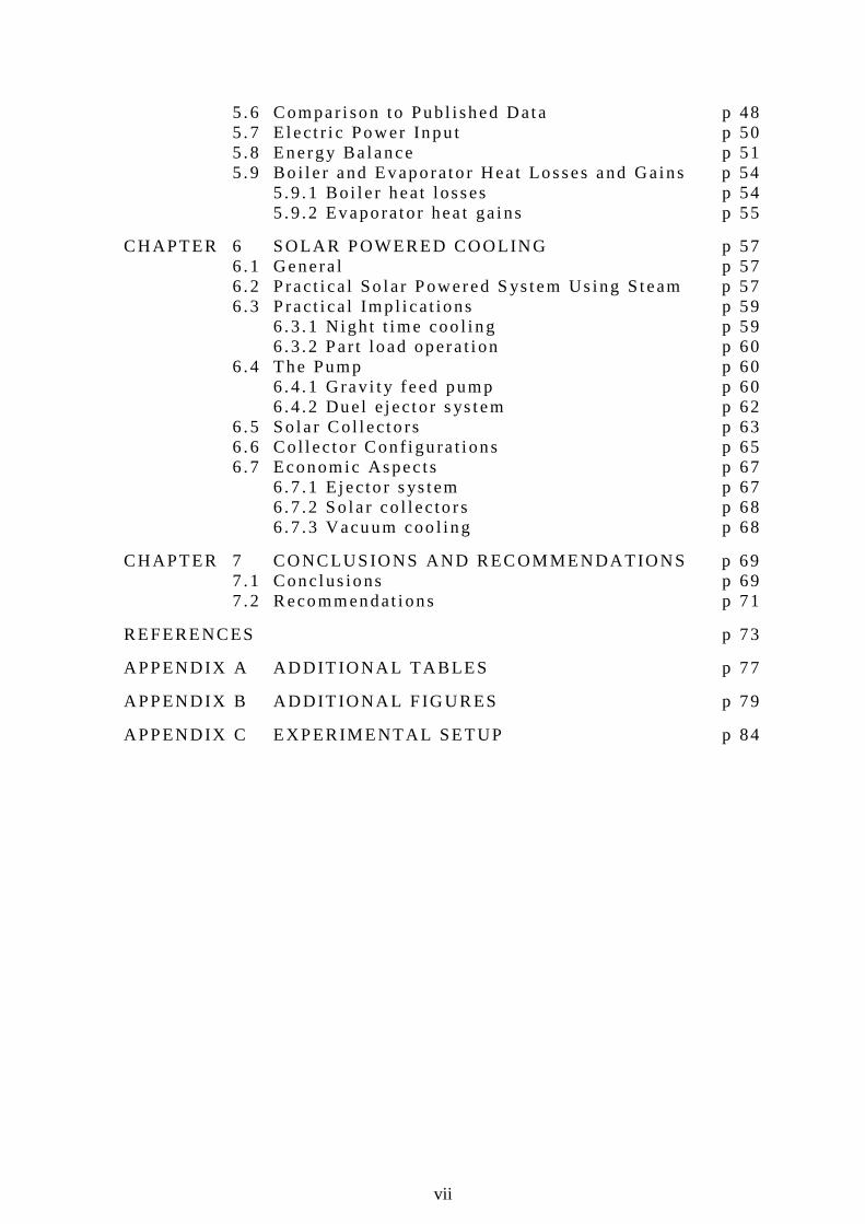
5 .6 Compar i son to Pub l i shed Data p 48 5 .7 E lec t r i c Power Inpu t p 50 5 .8 Energy Ba lance p 51 5 .9 Bo i l e r and Evaporato r Heat Losses and Gains p 54 5 .9 .1 Bo i l e r heat losses p 54 5 .9 .2 Evaporator hea t ga ins p 55
CHAPTER 6 SOLAR POWERED COOLING p 57 6 .1 Genera l p 57 6 .2 P rac t i ca l So lar Powered S ys tem Us ing S team p 57 6 .3 P rac t i ca l Imp l i ca t ions p 59 6 .3 .1 N igh t t ime coo l i ng p 59 6 .3 .2 Par t load opera t i on p 60 6 .4 The Pump p 60 6 .4 .1 Grav i t y feed pump p 60 6 .4 .2 Duel e jec to r s ys tem p 62 6 .5 So la r Co l l ec to rs p 63 6 .6 Co l l ec to r Con f i gu ra t i ons p 65 6 .7 Economic Aspec ts p 67 6 .7 .1 E jec to r s ys tem p 67 6 .7 .2 So la r co l l ec to rs p 68 6 .7 .3 Vacuum coo l ing p 68
CHAPTER 7 CONCLUSIONS AND RECOMMENDATIONS p 69 7 .1 Conc lus ions p 69 7 .2 Recommendat i ons p 71
REFERENCES p 73
APPENDIX A ADDIT IONA L TABLES p 77
APPENDIX B ADDIT IONA L F IG URES p 79
APPENDIX C EXPERIMENTAL SETUP p 84
viii
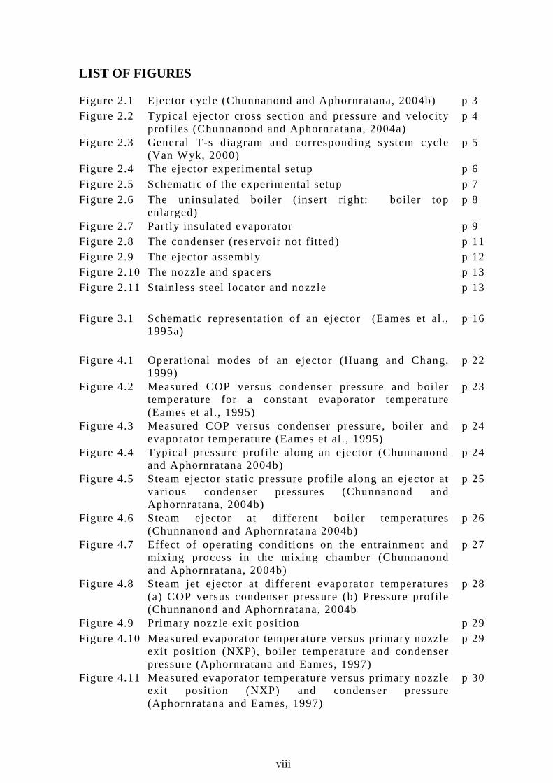
LIST OF FIGURES Figure 2.1 Ejector cycle (Chunnanond and Aphornratana, 2004b) p 3 Figure 2.2 Typical ejector cross section and pressure and velocity
profi les (Chunnanond and Aphornratana, 2004a) p 4
Figure 2.3 General T-s diagram and corresponding system cycle (Van Wyk, 2000)
p 5
Figure 2.4 The ejector experimental setup p 6 Figure 2.5 Schematic of the experimental setup p 7 Figure 2.6 The uninsulated boiler ( insert right: boiler top
enlarged) p 8
Figure 2.7 Part ly insulated evaporator p 9 Figure 2.8 The condenser (reservoir not fi tted) p 11 Figure 2.9 The ejector assembly p 12 Figure 2.10 The nozzle and spacers p 13 Figure 2.11 Stainless steel locator and nozzle p 13 Figure 3.1 Schematic representation of an ejector (Eames et al .,
1995a) p 16
Figure 4.1 Operational modes of an ejector (Huang and Chang,
1999) p 22
Figure 4.2 Measured COP versus condenser pressure and boiler temperature for a constant evaporator temperature (Eames et al ., 1995)
p 23
Figure 4.3 Measured COP versus condenser pressure, boiler and evaporator temperature (Eames et al. , 1995)
p 24
Figure 4.4 Typical pressure profi le along an ejector (Chunnanond and Aphornratana 2004b)
p 24
Figure 4.5 Steam ejector static pressure profi le along an ejector at various condenser pressures (Chunnanond and Aphornratana, 2004b)
p 25
Figure 4.6 Steam ejector at different boiler temperatures (Chunnanond and Aphornratana 2004b)
p 26
Figure 4.7 Effect of operat ing conditions on the entrainment and mixing process in the mixing chamber (Chunnanond and Aphornratana, 2004b)
p 27
Figure 4.8 Steam jet ejector at different evaporator temperatures (a) COP versus condenser pressure (b) Pressure profi le (Chunnanond and Aphornratana, 2004b
p 28
Figure 4.9 Primary nozzle exit posit ion p 29 Figure 4.10 Measured evaporator temperature versus primary nozzle
exit posit ion (NXP), boiler temperature and condenser pressure (Aphornratana and Eames, 1997)
p 29
Figure 4.11 Measured evaporator temperature versus primary nozzle exit posit ion (NXP) and condenser pressure (Aphornratana and Eames, 1997)
p 30
ix
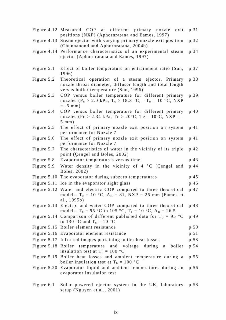
Figure 4.12 Measured COP at different primary nozzle exit posit ions (NXP) (Aphornratana and Eames, 1997)
p 31
Figure 4.13 Steam ejector with varying primary nozzle exit posit ion (Chunnanond and Aphornratana, 2004b)
p 32
Figure 4.14 Performance characteristics of an experimental steam ejector (Aphornratana and Eames, 1997)
p 34
Figure 5.1 Effect of boiler temperature on entrainment ratio (Sun,
1996) p 37
Figure 5.2 Theoretical operation of a steam ejector. Primary nozzle throat diameter, di ffuser length and total length versus boiler temperature (Sun, 1996)
p 38
Figure 5.3 COP versus boiler temperature for di fferent primary nozzles (Pc > 2.0 kPa, Tc > 18.3 °C, Te = 10 °C, NXP = -5 mm)
p 39
Figure 5.4 COP versus boiler temperature for di fferent primary nozzles (Pc > 2.34 kPa, Tc > 20°C, Te = 10°C, NXP = -5 mm)
p 40
Figure 5.5 The effect of primary nozzle exit posit ion on system performance for Nozzle 7
p 41
Figure 5.6 The effect of primary nozzle exit posit ion on system performance for Nozzle 7
p 41
Figure 5.7 The characteristics of water in the vicini ty of i ts tr iple point (Çengel and Boles, 2002)
p 42
Figure 5.8 Evaporator temperatures versus time p 43 Figure 5.9 Water density in the vicinity of 4 °C (Çengel and
Boles, 2002) p 44
Figure 5.10 The evaporator during subzero temperatures p 45 Figure 5.11 Ice in the evaporator sight glass p 46 Figure 5.12 Water and electric COP compared to three theoretical
models. Te = 10 °C, AR = 81, NXP = 26 mm (Eames et al. , 1995b)
p 47
Figure 5.13 Electric and water COP compared to three theoretical models. Tb = 95 °C to 105 °C, Te = 10 °C, AR = 26.5
p 48
Figure 5.14 Comparison of different publ ished data for Tb = 95 °C to 130 °C and Tc = 10 °C
p 49
Figure 5.15 Boi ler element resistance p 50 Figure 5.16 Evaporator element resistance p 51 Figure 5.17 Infra red images pertaining boiler heat losses p 53 Figure 5.18 Boi ler temperature and voltage during a boiler
insulation test at Tb = 100 °C p 54
Figure 5.19 Boi ler heat losses and ambient temperature during a boiler insulation test at Tb = 100 °C
p 55
Figure 5.20 Evaporator l iquid and ambient temperatures during an evaporator insulation test
p 56
Figure 6.1 Solar powered ejector system in the UK, laboratory
setup (Nguyen et al., 2001) p 58

x
Figure 6.2 Experimental data from a steam jet ejector cooling system installed in the UK (Tony, 2005)
p 59
Figure 6.3 Solar powered steam jet ejector system in the UK, installation layout (Nguyen et al. , 2001)
p 61
Figure 6.4 Dual ejector system, general layout (Shen et al ., 2005) p 62 Figure 6.5 Entrainment ratio for vapour-l iquid ejector for different
working fluids (Shen et al ., 2005) p 63
Figure 6.6 Efficiency comparison of three types of solar collectors with Tambien t = 25 °C and G = 900 W/m2 (Huang et al ., 2001) p 64
Figure 6.7 Solar thermal col lectors p 65 Figure 6.8 Solar powered ejector configurations (Sun and Eames,
1995) p 66
Figure B.1 Previous ejector setup at Stellenbosch University p 79 Figure B.2 Experimental setups from other authors (Aphornratana
and Eames, 1997, Left), (Chunnanond and Aphornratana, 2004, Right)
p 79
Figure B.3 IR and normal images of the condenser p 80 Figure B.4 IR and normal images of the evaporator p 80 Figure B.5 IR and normal images of the evaporator p 81 Figure B.6 Water and electric COP compared to three theoretical
models. Te = 10 °C, AR = 81, NXP = 26 mm (Eames et al. , 1995)
p 82
Figure B.7 Electric and water COP compared to three theoretical models. Tb = 95 °C to 105 °C, Te = 10 °C, AR = 26.5
p 82
Figure B.8 Comparison of different publ ished data for Tb = 95 °C to 130 °C and Tc = 10 °C
p 83
xi
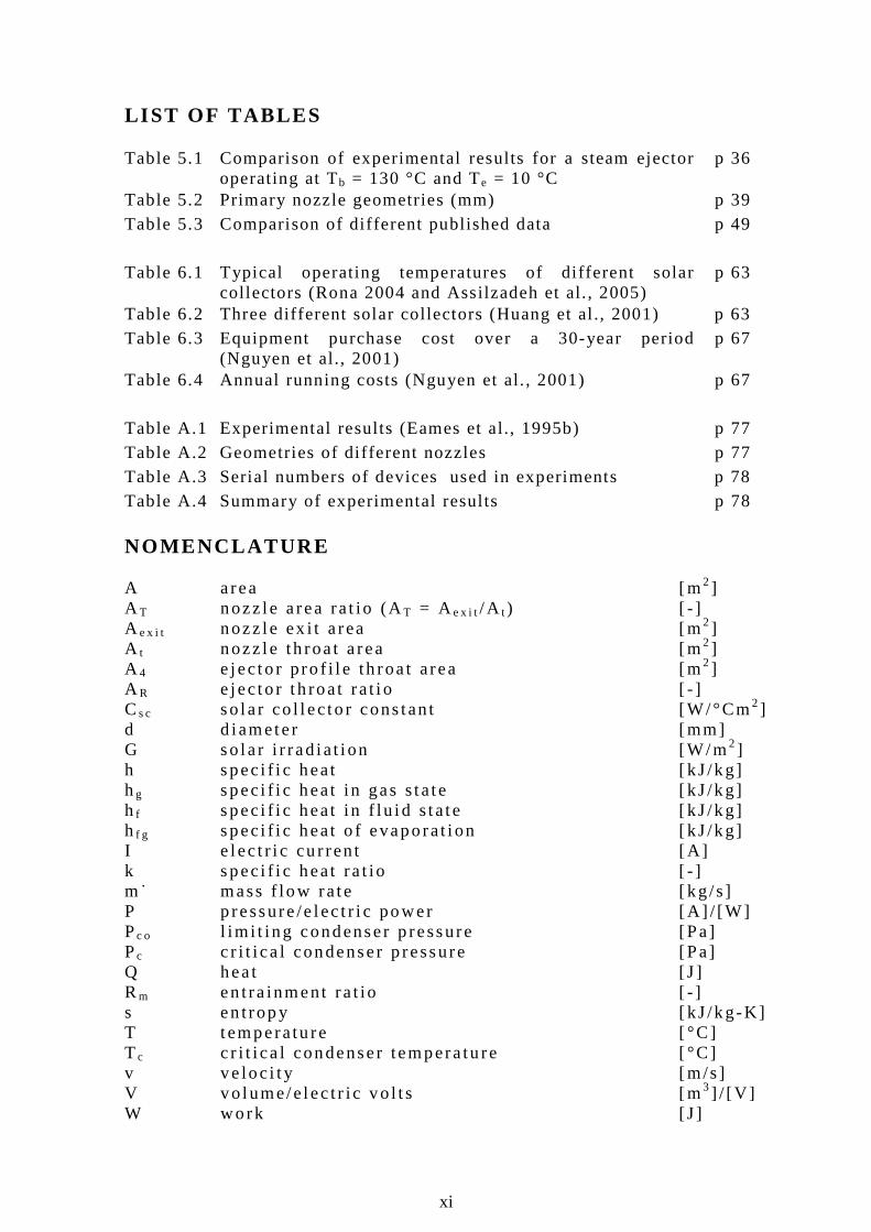
LIST OF TABLES Table 5.1 Comparison of experimental results for a steam ejector
operating at Tb = 130 °C and Te = 10 °C p 36
Table 5.2 Primary nozzle geometries (mm) p 39 Table 5.3 Comparison of di fferent published data p 49 Table 6.1 Typical operating temperatures of di fferent solar
collectors (Rona 2004 and Assilzadeh et al. , 2005) p 63
Table 6.2 Three different solar collectors (Huang et al ., 2001) p 63 Table 6.3 Equipment purchase cost over a 30-year period
(Nguyen et al., 2001) p 67
Table 6.4 Annual running costs (Nguyen et al. , 2001) p 67 Table A.1 Experimental results (Eames et al., 1995b) p 77 Table A.2 Geometries of di fferent nozzles p 77 Table A.3 Serial numbers of devices used in experiments p 78 Table A.4 Summary of experimental results p 78 NOMENCLATURE A a rea [m2 ] A T nozz le a rea ra t io (AT = Ae x i t /A t ) [ - ] A e x i t nozz le ex i t a rea [m2 ] A t nozz le th roa t a rea [m2 ] A 4 e j ec to r p ro f i l e th roa t area [m2 ] A R e jec to r t h roat ra t i o [ - ] Cs c so la r co l l ec to r cons tan t [W/ °Cm2 ] d d iamete r [mm] G so la r i r rad ia t i on [W/m2 ] h spec i f i c heat [ kJ /kg] hg spec i f i c heat in gas s ta te [ kJ /kg] h f spec i f i c heat in f lu i d s ta te [ kJ /kg] h f g spec i f i c heat o f evaporat i on [ kJ /kg] I e l ec t r i c cu r ren t [A ] k spec i f i c heat ra t io [ - ] m˙ mass f low ra te [ kg /s ] P pressure /e lec t r i c power [A ] / [W] Pc o l im i t ing condenser p ressure [Pa] Pc c r i t i ca l condenser p ressure [Pa] Q hea t [ J ] Rm en t ra inment ra t io [ - ] s en t rop y [ kJ /kg-K] T t emperatu re [ °C ] T c c r i t i ca l condenser tempera tu re [ °C ] v ve loc i t y [m/s ] V vo lume/e lec t r i c vo l t s [m3 ] / [V ] W work [ J ]

xii
NOMENCLATURE, (cont inue) Greek symbo ls η e f f i c i ency [%] ρ dens i t y [ kg /m3 ] Ω e l ec t r i c res i s tance [ ohms] Subscr ip t s a ambien t b bo i le r c condenser d d i f fuser e evaporato r / ex i t f f l u id e lec e lec t r i ca l g gas (vapour ) i i n l e t m m ix ing chamber / mean o ou t le t sc so la r co l l ec to r 1 cons tan t p ressu re m ix ing sect ion 2 secondary nozz le th roat 3 pos i t i on be fore shock wave 4 pos i t i on a f ter shock wave / secondary nozz le t h roat 1 ’ p r imary nozz le ex i t 1 ” secondary f l ow in le t P p r imary nozz le t t h roat t heo theo re t i ca l ABBREVIATIONS AC a l t e rnat i ng cu r ren t CD compact d isk CFC ch lo ro f luorocarbon COP coe f f i c i en t o f pe r fo rmance HCFC h yd roch lo ro f l uo rocarbons HFC h yd ro f luo rocarbons ID i nner d iameter IR i n f ra red OD oute r d iameter PC persona l compute r PCM phase change mate r i a l PVC po l yv in yl ch lo r ide UK Un i ted K ingdom

1
1. INTRODUCTION H igh o i l p r i ces can be good news – i t d r i ves the research in to renewab le energy a l te rnat i ves . I t f u r the r p romotes the e f f i c i en t use o f energy and i t encourages peop le to seek ways o f u t i l i s i ng was te heat o r energy.
Waste p rocess heat and waste s team is common in indus t ry and i t can be app l i ed fo r hea t i ng , c l ean ing and abso rp t i on coo l ing cyc les a long w i th o ther uses . The app l i ca t ion o f was te heat i s dete rm ined b y the temperatu re o f the hea t o r s team. Waste hea t has more uses a t h igher t emperatu res . Waste s team and p rocess heat be low 100 °C is o f t en te rmed l ow grade was te hea t . The need fo r coo l ing i s common in many i ndus t r i es and ranges f rom p roduct re f r i ge ra t ion to space coo l i ng . The main a im o f t h i s thes is is t o i nves t i ga te the use o f low grade hea t to d r i ve a s team je t e jec to r coo l i ng cyc le . A s team je t e jec to r tha t can opera te a t a bo i l e r t empera ture o f 100 °C o r be low can eas i l y be powered b y convent i ona l f l a t p la te so lar wate r hea te rs . S ince the coo l ing l oad i s common ly s ynch ron ised w i th the ava i l ab i l i t y o f so lar energy, t h i s becomes an a t t rac t i ve app l i ca t ion o f so la r energy.
The ob jec t i ves o f th is p ro jec t a re :
1 ) Des ign and bu i l d a smal l sca le exper imenta l s team je t e jec to r
se tup. Chapte r 2 w i l l exp la in t he though t p rocess beh ind the des ign o f such a sys tem. I t w i l l f u r the r exp la in how such a setup was cons t ruc ted as wel l as the exper imen ta l method that was fo l lowed.
2 ) Exp la in t he f l u i d dynamic theory re levant to t he s team jet
e jec to r. Chapte r 3 w i l l exp la in t he f l u i d dynamic theory based on p resent l i t e ra tu re . Th is w i l l i nc lude the e f f i c i ency o f t he p r imary nozz le , t he mix ing chamber and the d i f fuser . Th i s t heo re t i ca l model i s compared to exper imenta l resu l ts i n chapte r 5 .
3 ) Exp la in the funct i on and f lu id dynamics o f a s team je t e jec tor
i n the con tex t o f a l i t e ra tu re s tudy.
The work o f va r i ous au tho rs on sma l l sca le s team e jec to rs w i l l be p resented i n chapte r 4 in the fo rm o f a l i t e ra tu re s tud y. The
2
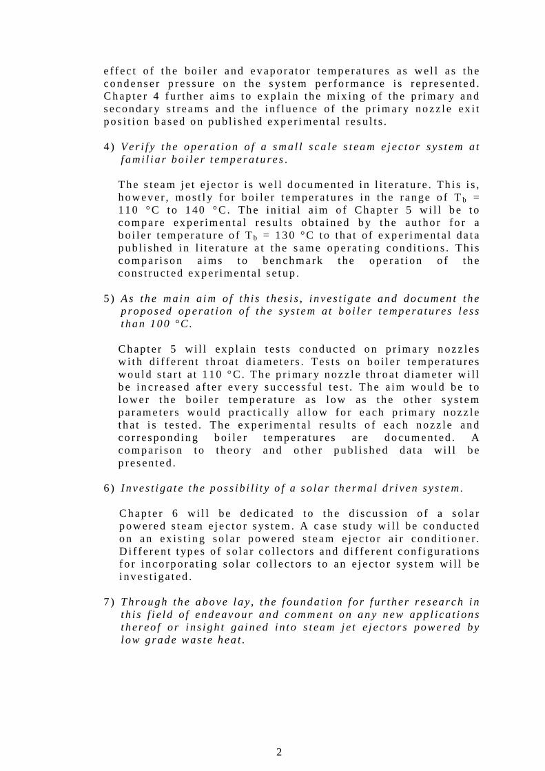
e f fec t o f t he bo i l e r and evaporato r tempera tu res as wel l as the condenser p ressu re on the s ys tem per fo rmance is rep resented . Chapte r 4 fu r the r a ims to exp la in the m ix ing o f the p r imary and secondary s t reams and the i n f luence o f t he p r imary nozz le ex i t pos i t i on based on pub l i shed exper imenta l resu l t s . 4 ) Ver i f y t he opera t i on o f a smal l sca le s team e jec tor sys tem a t
f ami l i a r bo i l e r t empera tu res.
The s team je t e jec to r i s we l l documented in l i t e ra tu re . Th is i s , however , most l y f o r bo i le r t empera tu res in the range o f Tb = 110 °C to 140 °C. The in i t i a l a im o f Chapte r 5 w i l l be to compare exper imen ta l resu l ts ob ta ined b y the au tho r fo r a bo i le r t empera tu re o f Tb = 130 °C to tha t o f ex per imenta l da ta pub l i shed i n l i t e ra tu re a t the same operat ing cond i t i ons . Th i s compar i son a ims to benchmark the opera t i on o f t he cons t ruc ted exper imenta l se tup .
5 ) As the main a im o f t h is t hes i s , inves t iga te and documen t the
p roposed opera t ion o f the sys tem a t bo i le r t empera tures l ess than 100 °C .
Chapte r 5 w i l l exp la in t es t s conducted on p r imary n ozz les w i th d i f fe ren t t h roa t d iamete rs . Tes ts on bo i l e r t emperatu res wou ld s ta r t a t 110 °C. The p r imary nozz le th roat d iameter w i l l be i nc reased a f te r every success fu l t es t . The a im wou ld be to l ower t he bo i l e r t emperatu re as low as the o ther sys tem paramete rs wou ld p rac t i ca l l y a l low fo r each p r imary n ozz le t hat i s t es ted . The ex per imen ta l resu l ts o f each nozz le and co r respond ing bo i le r t emperatures a re documented . A compar i son to t heo ry and o ther pub l i shed data w i l l be p resented .
6 ) I nves t i ga te the poss ib i l i t y o f a so la r the rmal d r i ven sys tem.
Chapte r 6 w i l l be ded i ca ted to the d i scuss ion o f a so la r powered s team e jec to r sys tem. A case s tudy w i l l be conduc ted on an ex is t i ng so la r powered s team e jec to r a i r cond i t ioner . D i f fe ren t t ypes o f so la r co l lec to rs and d i f fe ren t con f i gura t i ons fo r inco rpora t ing so lar co l l ec to rs to an e jec to r sys tem wi l l be i nves t i ga ted .
7 ) Through the above l ay , the foundat i on fo r f u r ther research i n
t h is f i e l d o f endeavour and comment on any new app l i ca t i ons thereo f o r i ns igh t ga ined i n to s team je t e jec to rs powered by l ow grade waste hea t .
3
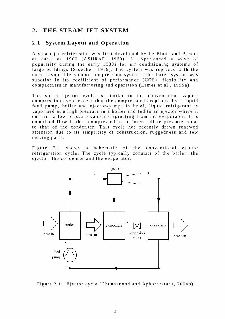
2. THE STEAM JET SYSTEM 2 .1 System Layout and Operat ion A s team je t re f r i gera to r was f i r s t deve loped b y Le B lanc and Parson as ear l y as 1900 (ASHRAE, 1969) . I t ex per ienced a wave o f popu la r i t y du r ing the ear l y 1930s fo r a i r cond i t i on ing s ys tems o f l a rge bu i ld ings (S toecker , 1959) . The s ys tem was rep laced wi th the more favourab le vapour compress ion s ys tem. The l a t t e r s ys tem was super io r i n i t s coe f f i c i en t o f pe r fo rmance (COP) , f lex ib i l i t y and compactness i n manu fac tu r i ng and opera t i on (Eames e t a l . , 1995a) . The s team e jec tor cyc le i s s im i la r t o the convent iona l vapour compress ion cyc le ex cept tha t the compresso r i s rep laced b y a l i qu id feed pump, bo i l e r and e jec to r -pump. In b r i e f , l i qu id re f r i ge ran t i s vapor i sed a t a h igh p ressure in a bo i l e r and fed to an e jec to r where i t en t ra ins a l ow p ressu re vapour o r i g ina t i ng f rom the evaporato r . Th i s combined f l ow i s then compressed to an i n te rmed ia te p ressu re equa l t o t hat o f t he condenser . Th is cyc le has recent l y d rawn renewed a t ten t i on due to i t s s imp l i c i t y o f cons t ruc t ion , ruggedness and few mov ing par ts . F igu re 2 .1 shows a schemat ic o f the convent i ona l e jec to r re f r i ge ra t i on cyc le . The cyc le t yp i ca l l y cons is ts o f t he bo i l e r , the e jec to r , the condenser and the evaporato r .
F igu re 2 .1 : E jec to r cyc le (Chunnanond and Aphorn ra tana, 2004b)
4
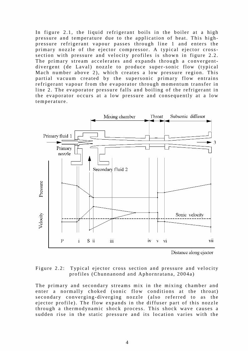
In f i gu re 2 .1 , the l i qu id re f r i ge ran t bo i l s i n the bo i le r a t a h igh p ressure and tempera tu re due to t he app l i ca t ion o f hea t . Th i s h igh-p ressure re f r i ge ran t vapour passes th rough l ine 1 and en te rs t he p r imary nozz le o f t he e jec to r compresso r . A t yp i ca l e jec to r c ross -sect ion w i th p ressu re and ve loc i t y p ro f i l es i s shown in f i gu re 2 .2 . The p r imary s t ream acce le ra tes and ex pands th rough a convergent -d ive rgent (de Lava l ) nozz le t o p roduce super -son i c f l ow ( t yp i ca l Mach number above 2 ) , wh i ch c reates a low p ressu re reg ion . Th is pa r t i a l vacuum c rea ted b y the superson i c p r imary f l ow en t ra ins re f r i ge ran t vapour f rom the evaporator t h rough momentum t rans fe r in l i ne 2 . The evapora tor p ressu re fa l l s and bo i l i ng o f t he re f r i ge ran t i n t he evaporato r occu rs a t a low pressu re and consequent l y a t a l ow temperatu re . F igu re 2 .2 : T yp i ca l e jec to r c ross sec t i on and p ressu re and ve loc i t y p ro f i les (Chunnanond and Aphornra tana, 2004a) The p r imary and secondary s t reams m ix in the mix ing chamber and en ter a no rmal l y choked (son i c f l ow cond i t i ons a t t he th roat ) secondary converg ing-d ive rg ing nozz le (a l so re fe r red to as the e jec to r p ro f i l e ) . The f l ow expands i n t he d i f fuser pa r t o f t h is nozz le t h rough a the rmodynamic shock p rocess . Th i s shock wave causes a sudden r i se i n the s ta t i c p ressu re and i t s locat ion var i es w i th the
5
condenser backp ressu re . The f low emerges f rom the shock wave wi th subson ic ve loc i t y and i s compressed in t he d i f fuser t o the satu ra t i on p ressure o f the condenser . F rom the d i f fuser ex i t , the m ixed f l ow i s fed d i rec t l y t o the condenser th rough l i ne 3 where i t i s coo led and condensed. The condensate i s re tu rned to t he evapora tor v i a an expans ion va l ve i n l i ne 6 and to t he bo i l e r th rough a feed pump in l i ne 4 . A fu l l desc r ip t ion o f e jec to r p r i nc ip les and per fo rmance and i ndus t r i a l app l i ca t ions can be found i n add i t iona l t ex t s (e .g . Eng ineer ing Sc iences Data Un i t , 1986) .
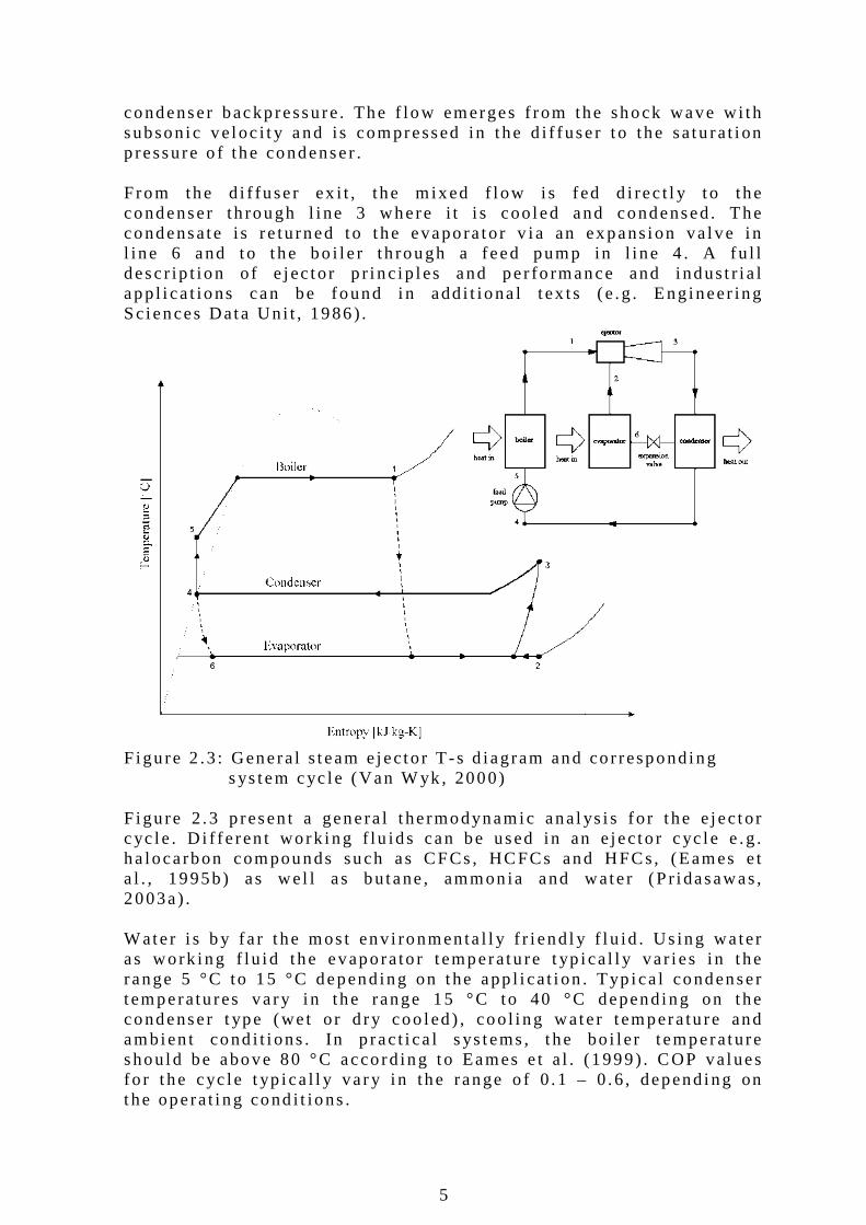
F igu re 2 .3 : Genera l s team e jec tor T -s d iagram and co r respond ing s ys tem cyc le (Van W yk , 2000) F igu re 2 .3 p resen t a genera l t he rmodynamic ana l ys i s fo r t he e jec to r cyc le . D i f fe ren t work ing f lu ids can be used in an e jec to r cyc le e .g . ha locarbon compounds such as CFCs , HCFCs and HFCs, (Eames e t a l . , 1995b) as wel l as bu tane , ammon ia and wate r (P r i dasawas, 2003a) . Wate r i s b y fa r t he mos t env i ronmen ta l l y f r i end l y f l u id . Us ing wa ter as work ing f lu i d the evaporato r t emperatu re t yp i ca l l y va r i es i n t he range 5 °C to 15 °C depend ing on the app l i ca t i on . Typ i ca l condenser t emperatu res va ry i n the range 15 °C to 40 °C depend ing on the condenser t ype (we t o r d ry coo led ) , coo l i ng wate r t empera tu re and ambien t cond i t i ons . In p rac t i ca l s ys tems , t he bo i l e r t emperature shou ld be above 80 °C acco rd ing to Eames e t a l . (1999) . COP va lues fo r t he cyc le t yp i ca l l y va r y i n the range o f 0 .1 – 0 .6 , depend ing on the opera t i ng cond i t ions .
6
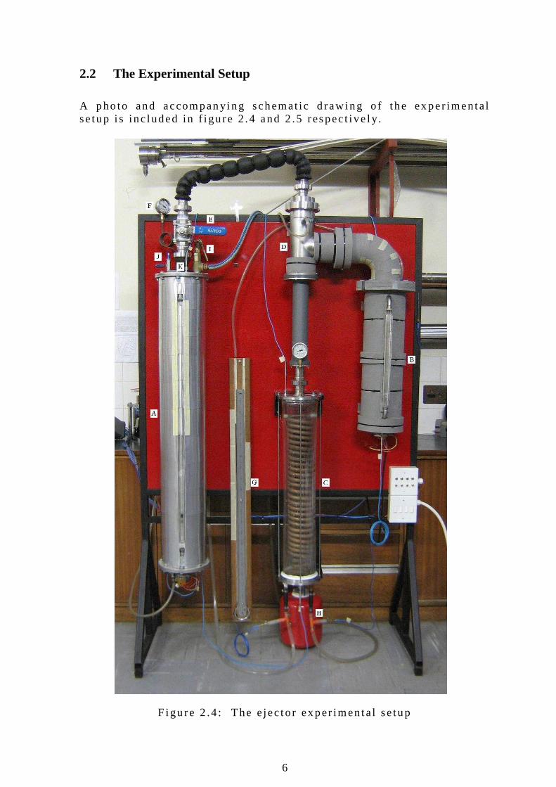
2.2 The Experimental Setup A pho to and accompan ying schemat ic d rawing o f the ex per imenta l se tup i s inc luded in f i gu re 2 .4 and 2 .5 respec t i ve l y.
F igu re 2 .4 : The e jec to r exper imen ta l se tup
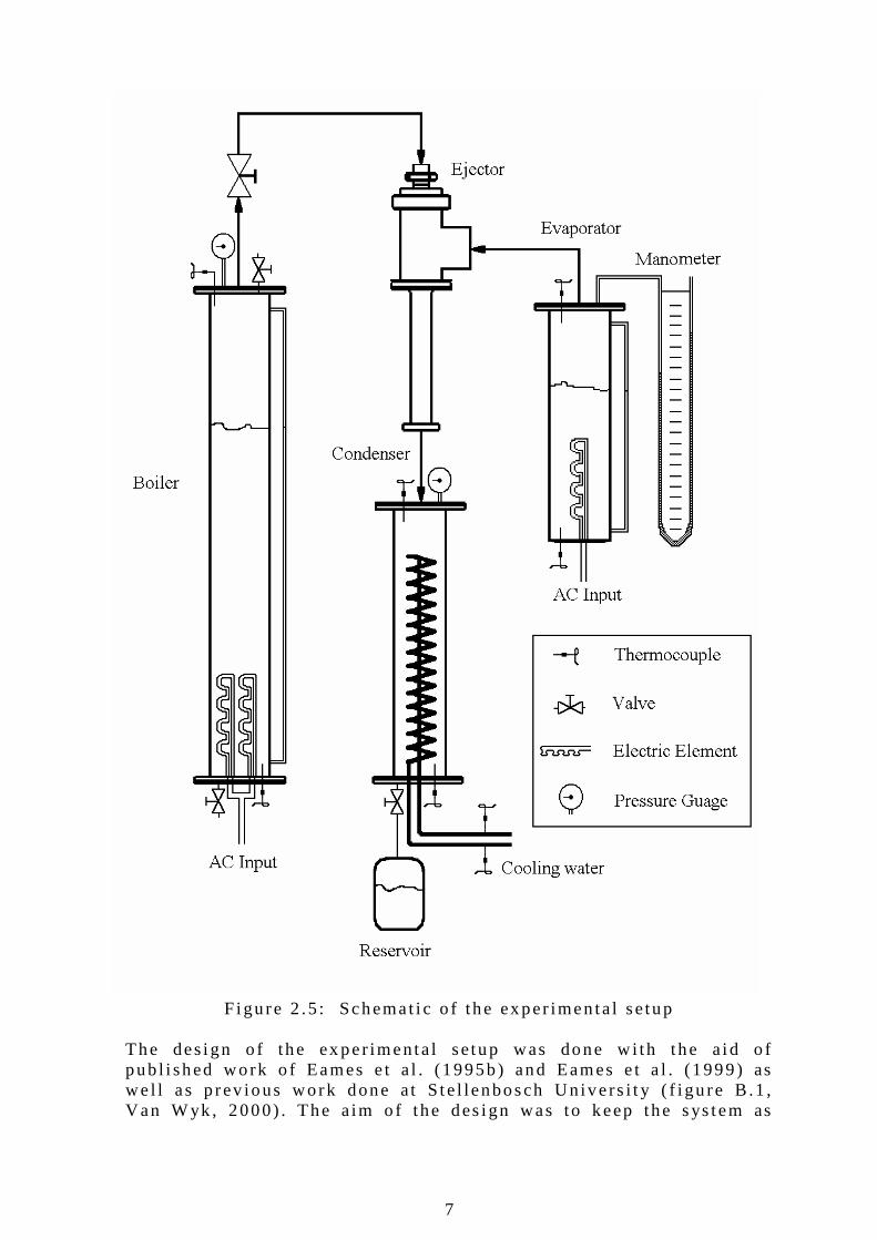
7
F igu re 2 .5 : Schemat i c o f the exper imen ta l se tup The des ign o f the ex per imenta l se tup was done w i th t he a id o f pub l i shed work o f Eames e t a l . (1995b) and Eames e t a l . (1999) as we l l as p rev ious work done a t S te l lenbosch Un ive rs i t y ( f i gu re B .1 , Van Wyk , 2000) . The a im o f the des ign was to keep the sys tem as
8
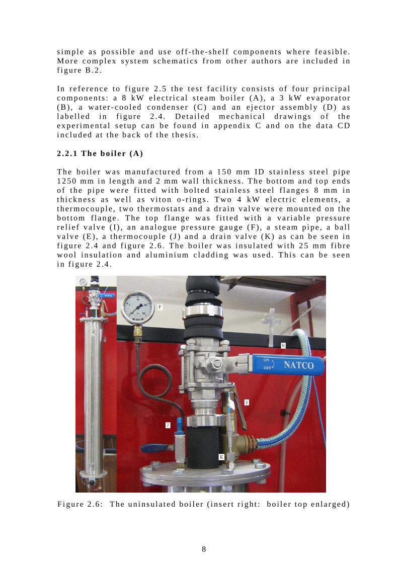
s imp le as poss ib le and use o f f - the -she l f components where feas ib le . More comp lex sys tem schemat i cs f rom o ther au tho rs a re i nc luded in f i gu re B .2 . In re fe rence to f i gu re 2 .5 the tes t fac i l i t y cons is ts o f fou r p r i nc ipa l components : a 8 kW e lec t r i ca l s team bo i l e r (A ) , a 3 kW evaporato r (B) , a wa ter -coo led condenser (C ) and an e jec to r assembl y (D) as l abe l l ed i n f i gu re 2 .4 . Deta i l ed mechan ica l d raw ings o f the ex per imenta l se tup can be found i n append ix C and on the da ta CD inc luded a t the back o f t he thes i s . 2 .2 .1 The bo i l e r (A ) The bo i l e r was manu fac tu red f rom a 150 mm ID s ta in less s tee l p ipe 1250 mm in length and 2 mm wa l l th i ckness . The bo t tom and top ends o f t he p ipe were f i t t ed w i th bo l t ed s ta in less s tee l f l anges 8 mm in t h i ckness as we l l as v i ton o - r ings . Two 4 kW e lec t r i c e lements , a t hermocoup le , two thermosta ts and a dra in va lve were mounted on the bo t tom f l ange . The top f l ange was f i t t ed w i th a va r iab le p ressu re re l i e f va lve ( I ) , an ana logue pressure gauge (F ) , a s team p ipe , a ba l l va lve (E ) , a the rmocoup le (J ) and a dra in va l ve (K) as can be seen in f i gu re 2 .4 and f i gure 2 .6 . The bo i le r was i nsu la ted w i th 25 mm f ib re woo l insu la t ion and a lumin ium c ladd ing was used. Th is can be seen i n f i gu re 2 .4 . F igu re 2 .6 : The un insu la ted bo i l e r ( inser t r i gh t : bo i l e r top en la rged)

9
The bo i l e r wate r leve l i s measured b y means o f a s igh t g lass . The s igh t g lass was manu fac tu red f rom a 12 mm OD and 2 mm wal l t h i ckness g lass tube . The bo i l e r has a to ta l vo lume o f 22 .1 L and the useab le vo lume ava i lab le between the top o f t he e lec t r i c e lements and the top o f t he s igh t g lass i s 15 .2 L . The bo i l e r was des igned to opera te a t Tb = 80 °C to 140 °C and the co r respond ing pressu re span o f Pb ≈ 45 kPa to 360 kPa . A t t he max imum s team f low o f 13 .5 kg /h (8 kW bo i l e r e lec t r i c energy i nput and Tb = 140 °C) the bo i l e r can p roduce s team fo r more than an hour . S team leaves the bo i l e r t h rough a 40 mm ID , 2 mm wa l l t h i ckness p ipe and ba l l va lve (E) . The bo i l e r was h yd ros ta t i ca l l y t es ted up to 400 kPa be fo re i t was f i t t ed . 2 .2 .2 The evapora to r (B ) The evaporato r ( f igu re 2 .7 ) was manu fac tu red f rom a 150 mm ID s ta in less s tee l p ipe 600 mm in l ength and 2 mm wa l l th i ckness . The bo t tom end was welded c losed and f i t ted w i th a 3 kW e lec t r i c e lemen t and a the rmocoup le . The top end o f t he evaporato r has bo l t ed s ta in -l ess s tee l f l anges and an o - r ing and i s f i t t ed w i th a t hermocoup le and mercu ry manometer (G) . The wate r conten t i s measured w i th a s ight g lass s im i l a r t o that o f t he bo i l e r . The to ta l vo lume o f the evaporato r i s 10 .6 L and the useab le vo lume be tween the top o f t he e lec t r i c e lement and the top o f the s igh t g lass i s 4 .1 L.
F igu re 2 .7 : Par t l y i nsu la ted evaporator
10
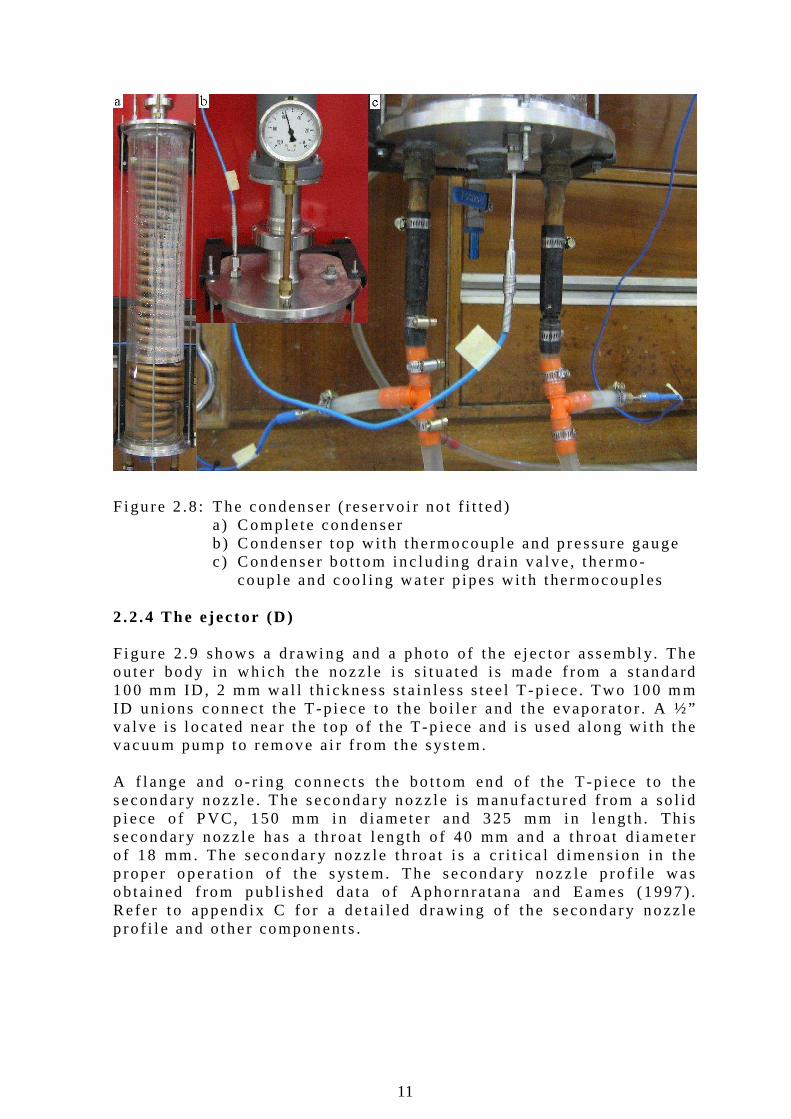
Wate r vapour f l ows f rom the evaporato r t o t he e jec to r t h rough a s ta in less s tee l p ipe and e lbow, bo th 100 mm ID . The connect i on be tween the evapora to r p ipe and e jec to r i s done wi th a 100 mm ID s ta in less s tee l un ion . A connect i on p ipe w i th a l a rge d iamete r was chosen due to the h igh spec i f i c vo lume o f s team a t low temperatu res (147 .1 m3 / kg a t 5 °C and 77 .9 m3 / kg a t 15 °C versus 1 .67 m3 / kg a t 100 °C) . A l a rge d iameter p ipe i s necessary to ensu re a l ow vapour ve loc i t y. W i th t he evaporato r opera t ing a t max imum e lec t r i c inpu t o f 3 kW and a t an evaporato r t empera ture o f 5 °C the s team ve loc i t y i n t he 100 mm ID p ipe i s 22 .6 m /s . The evaporato r vapour and l iqu id t empera tu res a re measured w i th separa te the rmocoup les ( f i gu re 2 .5 ) . The p ressu re w i th in t he evaporato r i s de term ined b y means o f t he s team tab les as we l l as w i th t he mercu ry manomete r (G) . A d i f fe rence between these two p ressures ment i oned i nd i ca tes the p resence o f a i r in the evaporato r . The evapora to r i s insu la ted w i th 10 mm th i ck A rmaf lex insu la t i on . The e lec t r i c e lemen t s imu la tes the evaporato r coo l ing l oad . Th i s e lement i s con t ro l led w i th a va r i ac . 2 .2 .3 The condenser (C) A bo i l e r un i t f rom a p rev ious exper imenta l se tup ( f i gure B .1 ) was mod i f i ed to a condenser ( f i gu re 2 .8 ) . A 150 mm d iamete r Perspex p ipe 800 mm long and w i th 3 mm wa l l th i ckness i s f i t t ed w i th s ta in less s tee l f l anges . S i l i cone was used to ensu re an a i r t i gh t j o i n t be tween the Perspex and endp la tes . The top p la te i s f i t t ed w i th a t hermocoup le and an ana logue p ressu re gauge . Th i s p la te a lso connects t o t he bo t tom o f the e jec to r t h rough a 40 mm s ta in less s tee l p ipe and un ion as can be seen i n f i gu re 2 .8 . The bo t tom p la te has a d ra in va l ve , the rmocoup le and a coo l i ng wa te r i n l e t and ou t l e t . Ins ide the condenser i s a copper coo l ing co i l . Th is co i l was manu fac tured f rom 15 mm OD p la in copper p ipe and wound i n two sp i ra l s . The ou te r sp i ra l has an OD o f 120 mm and the i nner sp i ra l has an OD o f 85 mm. 15 m o f copper p ipe was used and the wounded co i l i s approx imate l y 700 mm long. The temperatu re ins ide the condenser i s con t ro l l ed by the coo l ing wa te r f low ra te . The min imum temperatu re in t he condenser i s l im i ted b y the temperatu re o f t he coo l i ng wa te r . The to ta l vo lume o f the condenser i s 14 .1 L w i thout the coo l i ng co i l . The vo lume o f the condenser w i th t he coo l i ng co i l f i t t ed i s 11 .5 L. The coo l ing wate r i n l e t and ou t l e t p ipes a re bo th f i t t ed w i th the rmocoup les ( f i gu re 2 .8c) . A rece ive r t ank (H) w i th a capac i t y o f 8 L i s connected to t he ou t le t o f t he condenser . Th is t ank se rves as a reservo i r fo r the condensa te .
11
F igu re 2 .8 : The condenser ( reservo i r no t f i t t ed )
a ) Comple te condenser b ) Condenser t op w i th the rmocoup le and p ressure gauge c ) Condenser bo t tom inc lud ing d ra in va lve , t hermo- coup le and coo l ing wa te r p ipes w i th the rmocoup les
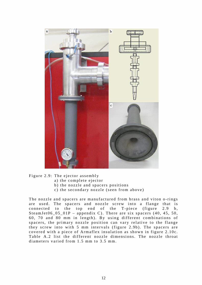
2 .2 .4 The e jec to r (D) F igu re 2 .9 shows a d rawing and a photo o f the e jec to r assembl y. The ou te r body i n wh ich the nozz le i s s i t ua ted i s made f rom a s tandard 100 mm ID , 2 mm wa l l th ickness s ta in less s tee l T -p iece. Two 100 mm ID un ions connect t he T -p iece to t he bo i le r and the evaporato r . A ½” va lve i s l ocated near the top o f the T-p iece and is used a long w i th t he vacuum pump to remove a i r f rom the sys tem. A f l ange and o - r i ng connects the bo t tom end o f the T -p iece to t he secondary nozz le . The secondary nozz le i s manu fac tu red f rom a so l id p iece o f PVC, 150 mm in d iameter and 325 mm in l ength . Th i s secondary nozz le has a th roat l eng th o f 40 mm and a th roat d iamete r o f 18 mm. The secondary nozz le t h roa t i s a c r i t i ca l d imens ion i n the p roper opera t ion o f the s ys tem. The secondary nozz le p ro f i l e was ob ta ined f rom pub l i shed data o f Aphorn ra tana and Eames (1997) . Re fe r t o append ix C fo r a de ta i l ed d raw ing o f t he secondary nozz le p ro f i l e and o ther components .
12
F igu re 2 .9 : The e jec to r assembl y a ) t he comple te e jec to r b ) t he nozz le and spacers pos i t i ons c ) t he secondary nozz le (seen f rom above) The nozz le and spacers are manu fac tured f rom b rass and v i t on o - r i ngs a re used. The spacers and nozz le sc rew in to a f lange that i s connected to t he top end o f t he T -p iece ( f i gu re 2 .9 b , S teamJ et06_05_01P – append ix C ) . There are s ix spacers (40 , 45 , 50 , 60 , 70 and 80 mm in l ength ) . By us ing d i f fe ren t combina t i ons o f spacers , the p r imary nozz le pos i t i on can va ry re la t i ve to the f l ange they sc rew in to w i th 5 mm in terva l s ( f i gu re 2 .9b ) . The spacers a re covered w i th a p iece o f A rmaf lex i nsu la t i on as shown in f i gu re 2 .10c . Tab le A .2 l i s t the d i f fe ren t nozz le d imens ions . The nozz le t h roat d iamete rs va r i ed f rom 1 .5 mm to 3 .5 mm.
13
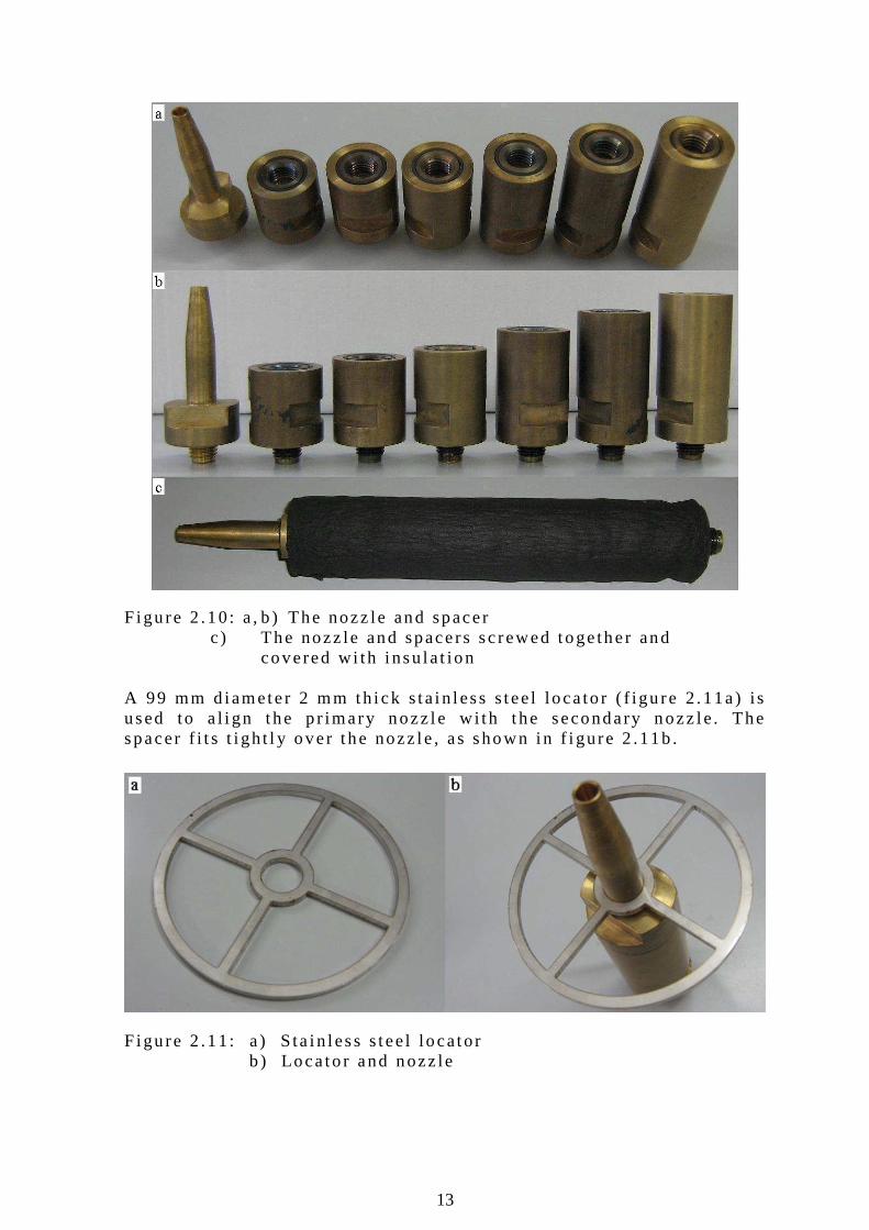
F igu re 2 .10 : a , b ) The nozz le and spacer
c ) The nozz le and spacers sc rewed toge ther and covered w i th i nsu la t ion
A 99 mm d iamete r 2 mm th i ck s ta in less s tee l loca to r ( f igu re 2 .11a) i s used to a l i gn the p r imary nozz le w i th t he secondary nozz le . The spacer f i t s t i gh t l y over t he nozz le , as shown in f i gure 2 .11b . F igu re 2 .11 : a ) S ta in less s tee l locator
b ) Loca to r and nozz le
14
2 .2 .5 O ther componen ts A 40 mm ID , 2 mm wal l th ickness s ta in less s tee l p ipe connects t he bo i le r and e jec to r assemb ly. Th is p ipe i s t i l t ed a t an ang le o f 15 ° f rom the ho r izon . Condensa te that fo rms i ns ide the p ipe can run back to the bo i l e r ( f i gure 2 .4 ) . The p ipe i s covered w i th 10 mm th i ck A rmaf lex insu la t i on . A data logger connec ted to a PC i s used to log the tempera tu res f rom the T- t ype the rmocoup les . The vo l t age to each e lec t r i c e lement i s a l so reco rded . The se r i a l numbers o f the equ ipment used can be found i n tab le A .3 . The tes t fac i l i t y has no pump between the condenser and bo i l e r and no expans ion va lve be tween the condenser and evapora tor . Such a s ys tem is t e rmed an open l oop sys tem. 2.3 The Exper imenta l Test Procedure Ex per imen ts are execu ted i n batches . Be fo re each tes t run the bo i l e r and evaporato r are f i l l ed w i th mun ic ipa l t ap water up to a p redete rmined l eve l near the top o f the s igh t g lass . The bo i l e r va l ve i s c losed and a i r i s evacuated f rom the bo i l e r by us ing a wate r - j e t vacuum pump connec ted to the top o f t he bo i l e r . The nex t s tep i s t o swi t ch the bo i l e r e lec t r i c e lemen ts on . Wh i l e the bo i l e r hea ts up to i t s opera t i ng temperatu re , t he vacuum pump is used to evacuate a i r f rom the res t o f the sys tem. The s team p ipe , e jec to r assemb ly, evaporato r and condenser a re a l l connected to each o ther w i thout an y va l ves . The vacuum pump is connec ted to the top o f t he e jec to r T -p iece. When the bo i l e r i s a t i t s opera t i ng temperatu re the bo i le r va lve i s opened . Th is a l lows the connect i on p ipe between the bo i le r and e jec to r t o be hea ted . I t a lso serves to d r i ves ou t the a i r s t i l l t rapped in the connect ion p ipe . The bo i l e r va lve i s on l y opened fo r about f i ve seconds a t a t ime . The bo i l e r va lve i s opened and c losed fo r a few t imes wh i l e the vacuum pump i s runn ing . Th is i s done un t i l t he a i r i s removed f rom the connect ion p ipe and the res t o f the s ys tem. Nex t , t he bo i l e r va l ve i s c l osed and the bo i l e r wate r l eve l i s re f i l l ed to the predete rmined l eve l . The bo i le r i s reheated to i t s opera t ing temperatu re . The coo l ing wa te r supp ly t o t he condenser i s tu rned on and the da ta l ogger i s swi t ched on . To s ta r t a t es t run , the bo i l er va lve i s opened. An immed ia te r i se in condenser p ressu re i s observed wh i l e t he evapora tor t empera tu re fa l l s rap id l y. The bo i l e r and evaporato r t emperatu res a re cont ro l l ed w i th a var i ac . The the rmos ta t on each bo i l e r e lement ac t s as an over - temperatu re and thus an over -p ressure p ro tec t ion . The bo i l e r and evaporato r mass f l ow ra te i s de termined by m easur ing the to ta l amount o f l i qu id t hat was conver ted in to s team over t he en t i re t ime in terva l o f the tes t run .
15
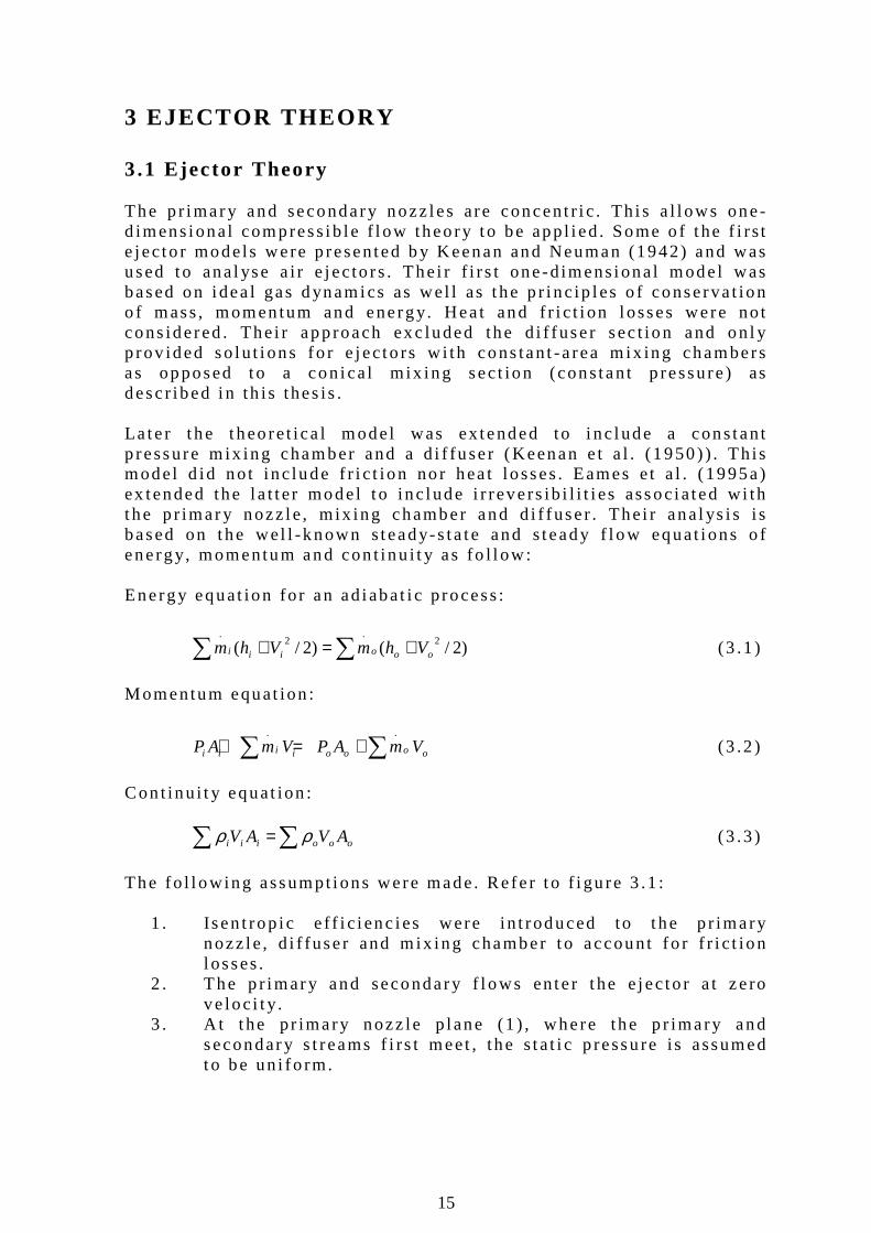
3 EJECTOR THEORY 3.1 Ejector Theory The p r imary and secondary nozz les are concent r i c . Th i s a l l ows one-d imens iona l compress ib le f l ow theo ry to be app l i ed . Some o f t he f i rs t e jec to r models were p resented b y Keenan and Neuman (1942) and was used to ana l yse a i r e jec to rs . The i r f i r s t one-d imens iona l mode l was based on i dea l gas d ynamics as wel l as the p r i nc ip les o f conserva t ion o f mass , momentum and energy. Hea t and f r i c t i on l osses were no t cons idered . The i r app roach exc luded the d i f fuser sec t ion and on l y p rov ided so lu t i ons fo r e jec to rs w i th cons tan t -a rea m ix ing chambers as opposed to a con i ca l m ix ing sect ion (cons tan t p ressure ) as desc r ibed i n th is thes is . La te r t he theo re t i ca l model was ex tended to i nc lude a cons tan t p ressure m ix ing chamber and a d i f fuser (Keenan e t a l . (1950) ) . Th is model d id no t inc lude f r i c t ion no r hea t losses . Eames e t a l . (1995a) ex tended the l a t t e r model t o inc lude i r revers ib i l i t i es assoc ia ted w i th t he p r imary nozz le , m ix ing chamber and d i f fuser . The i r ana l ys i s i s based on the wel l -known s teady-s ta te and s teady f l ow equat i ons o f energy, momentum and con t inu i t y as fo l l ow : Energy equat ion fo r an ad iabat i c p rocess :
∑ ∑ +=+ )2/()2/( 2.
2.
oooiii VhmVhm (3 .1 )
Momentum equat ion :
∑ ∑+=+ ooooiiii VmAPVmAP..
(3 .2 )
Con t inu i t y equat ion : ∑ ∑= oooiii AVAV ρρ (3 .3 )
The fo l l owing assumpt ions were made. Re fe r t o f i gu re 3 .1 :
1 . Isen t rop i c e f f i c i enc ies were in t roduced to t he p r imary nozz le , d i f fuser and m ix ing chamber t o account fo r f r i c t ion l osses .
2 . The p r imary and secondary f l ows en te r t he e jec to r a t ze ro ve loc i t y.
3 . At the pr imary nozz le p lane (1 ) , where the p r imary and secondary s t reams f i rs t meet , the s ta t i c p ressu re i s assumed to be un i fo rm.
16
4 . Mix ing o f the p r imary and secondary f l ows i s comple te be fo re a normal shock wave occu rs a t t he end o f the mix ing chamber .
The en t ra inmen t ra t io o f an e jec to r i s de f i ned as the ra t i o between the e jec to r (secondary) and bo i l e r (p r imary) f l u id mass f low ra tes :
b
e
m
m
mR
.
.
= (3 .4 )
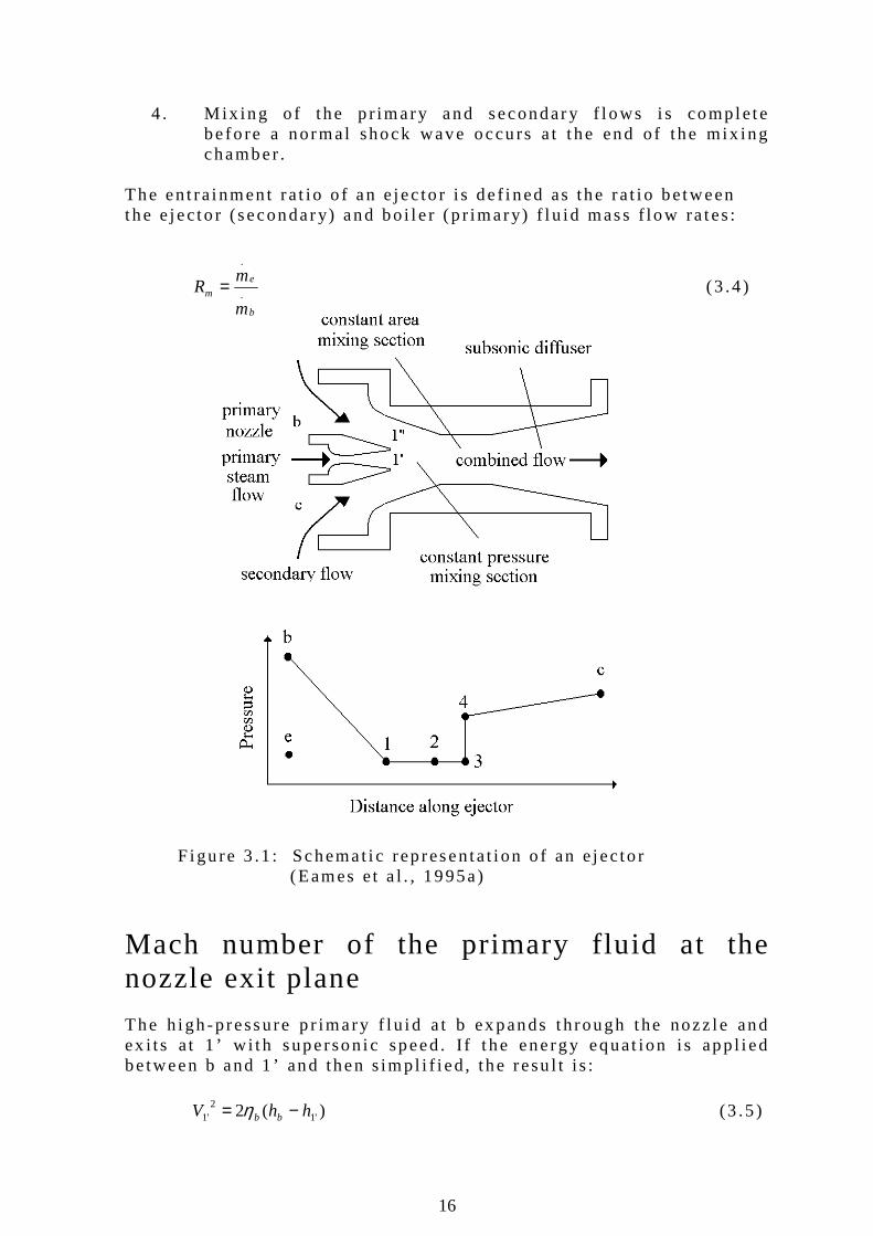
F igu re 3 .1 : Schemat i c rep resenta t i on o f an e jec to r (Eames e t a l . , 1995a)
Mach number of the primary fluid at the nozzle exit plane The h igh -pressure p r imary f l u i d a t b ex pands th rough the nozz le and ex i ts a t 1 ’ w i t h superson i c speed. I f t he energy equat ion i s app l i ed be tween b and 1 ’ and then s imp l i f i ed , the resu l t i s :
)(2 '12
'1 hhV bb −= η (3 .5 )
17
where Pη i s an i sen t rop i c e f f i c i ency o f the p r imary nozz le . The re la t ion between the p ressu re ra t i o ac ross the nozz le and Mach number a t the ex i t o f t he nozz le i s g i ven as :
−
−=
−
11
21
1'1
k
k
bp
P
P
kM
η (3 .6 )
Mach number of the secondary fluid at the nozzle exit plane The secondary f l ow ex pands f rom e to 1 ” . The Mach number fo r t he secondary f l ow a t t he nozz le ex i t p lane i s de r ived i n a s im i l a r fash ion :
−
−=
−
11
21
1''1
k
k
e
P
P
kM (3 .7 )
The mixing process The momentum equa t i on fo r idea l m ix ing i s app l i ed be tween 1 and 3 :
3
..
33"1
.
'1
.
11 )( VmmAPVmVmAP ebeb ++=++ (3 .8 )
Two assumpt ions a re made. The en t i re m ix ing p rocess be tween p r imary and secondary f l ows occu r between 1 and 3 a t cons tan t s ta t i c p ressure (P1 = P3) . The c ross -sec t i ona l a reas a t the i n l e t and ex i t o f t he m ix ing chamber a re equa l (A1 = A3) . There fo re :
3
..
"1
.
'1
.
)( VmmVmVm ebeb +=+ (3 .9 )
The above re la t i on desc r i bes fu l l y i dea l i zed m ix ing and mη i s
i nc luded as an e f f i c i ency fo r t he en t i re m ix ing chamber :
3
..
"1
.
'1
.
)()( VmmVmVm ebebm +=+η (3 .10 )
18
The ve loc i t y o f t he mixed f lu i d a t 3 can be exp l i c i t l y exp ressed as :
+
+=
eb
eb
m
mm
VmVmV
.."1
.
'1
.
3 η (3 .11 )
Equa t i on (3 .11 ) can be rewr i t t en i n t e rms o f t he Mach number :
)/1)(1(
/*"1
*'1*
3
bemm
bem
TTRR
TTMRMM
+++
= (3 .12 )
where the re la t ionsh ip between M and M* i s g i ven as :
2/)1(1
2/)1(2
2*
Mk
MkM
−++= (3 .13 )
Pressure ratio across a normal shock wave A no rma l shock wave occu rs w i th in the cons tan t -a rea mix ing sec t i on i f t he ve loc i t y o f the mixed f low en ter i ng th i s sec t i on i s superson i c . Du r i ng the shock process the f l ow exper i ences a sudden change in t he f l ow ve loc i t y and p ressu re . Theore t i ca l l y t he shock wave has an i n f in i t es imal th i ckness . The shock occu r r i ng be tween 3 and 4 wou ld t here fo re be an i r reve rs ib le compress ion process in wh ich the Mach number sudden ly f a l l s to l ess t han un i t y. The Mach number o f the m ixed f l ow a f te r t he shock i s :
( )[ ] 1)1/2
)1/(22
3
23
4 −−−+
=Mkk
kMM (3 .14 )
The p ressu re l i f t ra t ion ac ross the shock wave i s :
2
4
23
3
4
1
1
kM
kM
P
P
++
= (3 .15 )
Pressure lift ratio across the subsonic diffuser The mix ed f low is fu r the r compressed as i t passes th rough the subson i c d i f f use r . In an add i t iona l assumpt ion , t he mix ed f l ow ve loc i t y reduces to zero a t t he d i f fuse r ex i t ( c ) . The p ressu re l i f t ra t i o ac ross the d i f f user i s :
19
12
44
12
)1( −
+−=k
k
dc Mk
P
P η (3 .16 )
Solu t i on o f Equa t ions (3 .5 ) – (3 .16 ) The temperatu re , p ressure and mass f l ow ra te o f t he p r imary and secondary f l u ids a re a l l known. Tempera tu res and p ressures a re taken f rom the thermocoup les and p ressure gauges . Mass f l ow ra te i s ca l cu la ted f rom the vo lume f l ow over a cer ta in t ime per iod . The fo l lowing p rocedure was used to ob ta in t he e jec to r exhaus t p ressu re .
1 The p ressu re a t t he nozz le ex i t p lane i s unknown and de termined b y an i t e ra t i ve p rocess . An in i t i a l va lue fo r ePP /1
i s guessed . 2 From equat i ons (3 .6 ) and (3 .7 ) t he Mach numbers o f t he
p r imary and secondary f l u ids a t the nozz le ex i t p lane ('1M
and "1M ) a re ca l cu la ted . 3 Equat i on (3 .12 ) i s used to ca l cu la te the Mach number o f t he
m ixed f l u id 3M .
4 Equat i on (3 .14 ) i s used to ca l cu la te the Mach number o f t he m ixed f l u id a f t e r the shock wave 4M .
5 Equat i on (3 .15 ) i s used the ca l cu la te t he p ressu re l i f t ra t i o ac ross the shock wave 34 / PP .
6 Equa t i on (3 .16 ) i s used to ca l cu la te t he p ressure l i f t ra t i o ac ross the d i f f use r 4/ PPc .
7 34 / PP , 4/ PPc and ePP /1 a re a l l known and the exhaus t p ressu re
cP can be ca l cu la ted .
8 Steps 1 to 7 a re repea ted w i th new va lues o f ePP /1 un t i l the
max imum cP i s ob ta ined .
Eames e t a l . (1995a) sugges ted va lues o f 0 .85 , 0 .85 and 0 .95 fo r t he p r imary nozz le , d i f fuse r and mix ing chamber e f f i c i enc ies respec -t i ve l y. Acco rd ing to t hese au tho rs , t hese va lues were found to g ive acceptab le co r re la t ion w i th exper imen ta l da ta p rov ided by ESDU (1986 ) . 3.2 Ejector Performance The thermodynamic pe r fo rmance o f a s team e jec to r i s eva luated by t he coe f f i c i en t o f pe r fo rmance. Th is i s the ra t i o o f t he evapora to r hea t l oad and the sum o f t he bo i l e r energy i npu t and pump work . The COP is ca l cu la ted as fo l lows :
20
boiler
evap
elecboiler
elecevap
pumpboiler
evap
VI
VI
P
P
WQ
QCOP
)(
)(
)(
)(
..
.
=≈+
= (3 .17 )
The pump work can be om i t t ed s ince i t i s t yp i ca l l y l ess t han 1% o f t he bo i l e r heat i npu t (Aphorn ra tana and Eames, 1997) . No te that Pe v a p ( e l e c ) and Pb o i l e r ( e l e c ) rep resent e lec t r i c power inpu t and no t p ressure and V represents e lec t r i c vo l t s and no t vo lume. The COP can a lso be ca l cu la ted as :
condfboilerg
condfevapgm hh
hhRCOP
−−
−−
−−
= (3 .18 )
where Rm was de f ined ear l ie r as :
b
e
m
m
mR
.
.
= (3 .19 )
Cer ta in au tho rs , however , use the te rms e lec t r i c and water COP when re fe r r i ng to t he COP and en t ra inment ra t i o . These te rms are def ined as fo l low:
condfboilerg
condfevapgwaterelec hh
hhCOPCOPCOP
−−
−−
−−
== (3 .20 )
and :
b
e
mwater
m
mRCOP
.
.
== (3 .21 )
F rom equat ions 3 .18 and 3 .19 i t can be observed that COPe l e c and COPw a t e r d i f fe r w i th a va lue o f :
condfboilerg
condfevapg
hh
hh
−−
−−
−−
(3 .22 )
The magn i tude o f t e rm (3 .20 ) i s t yp i ca l l y 0 .931 to 0 .946 fo r t he temperatu re ranges o f Te = 5 °C to 10 °C, Tc = 15 °C to 25 °C and T b = 90 °C to 110 °C. Th is resu l t s i n a COPw a t e r va lue wh ich i s 5 .7 % t o 7 .4 % h igher than the COPe l e c va lue. The COPw a t e r va lue i s usua l l y ca l cu la ted b y measur ing the change i n t he wa ter l eve l in t he bo i l e r and evapora to r s i gh t g lass . The dens i t y o f wa ter i n the evapora to r and bo i l e r d i f f e r be tween 95 .2 % to 96 .5 % (T e = 5 °C to 10 °C and Tb = 90 °C to 110 °C) . The e f fec t o f th i s
21
phenomenon i s tha t t he measured COPw a t e r i s 3 .5 % to 4 .8 % lower t han the ac tua l COPw a t e r va lue . The combined e f fec t o f t he two cases above resu l t s in t he measured COPw a t e r va lue be ing 2 .0 % to 2 .1 % h igher t hat the COPe l e c va lue. I f an ex per imen ta l se tup has no condensate re tu rn sys tem and batches a re run du r ing exper iments , the s ys tem becomes an open loop s ys tem. The open loop COPe l e c i s :
boilerfg
evapfgm
elecboiler
elecevapolelec h
hR
P
PCOP
−
−==_
_)( (3 .23 )
where, as be fo re , the c losed l oop COP is :
condfboilerg
condfevapgm
elecboiler
elecevapclelec hh
hhR
P
PCOP
−−
−−
−−
==_
_)(
condfboilerfboilerfg
condfevapfevapfgm hhh
hhhR
−−−
−−−
−+−+
= (3 .24 )
The COPe l e c ( o l ) and COPe l e c ( c l ) d i f fe r f rom each o ther w i th l ess than 0 .5 % in the fo l low ing temperatu re ranges Te = 5 °C to 10 °C, Tc = 15 °C to 25 °C and Tb = 95 °C to 105 °C . The exper imenta l se tup used i n th i s p ro jec t i s an open l oop sys tem s im i l a r to t hat o f Eames e t a l . (1999) . The pub l i shed exper imenta l data , however , i s re levant to a c losed l oop sys tem un less o therwise s ta ted . In t h i s t hes i s , when a graph o f exper imenta l data i s p lo t ted , t he te rms COPw a t e r and COPe l e c a re used. The term COP is used as a co l l ec t i ve te rm when re fe r r ing to t he sys tem per fo rmance i n genera l . Th is t e rm i s fu r the r used on the ax is o f a g raph when bo th COPe l e c and COPw a t e r a re p lo t t ed . The terms COP and Rm a re used on graphs taken f rom pub l i shed da ta and rep resent COPe l e c and COPw a t e r.
22
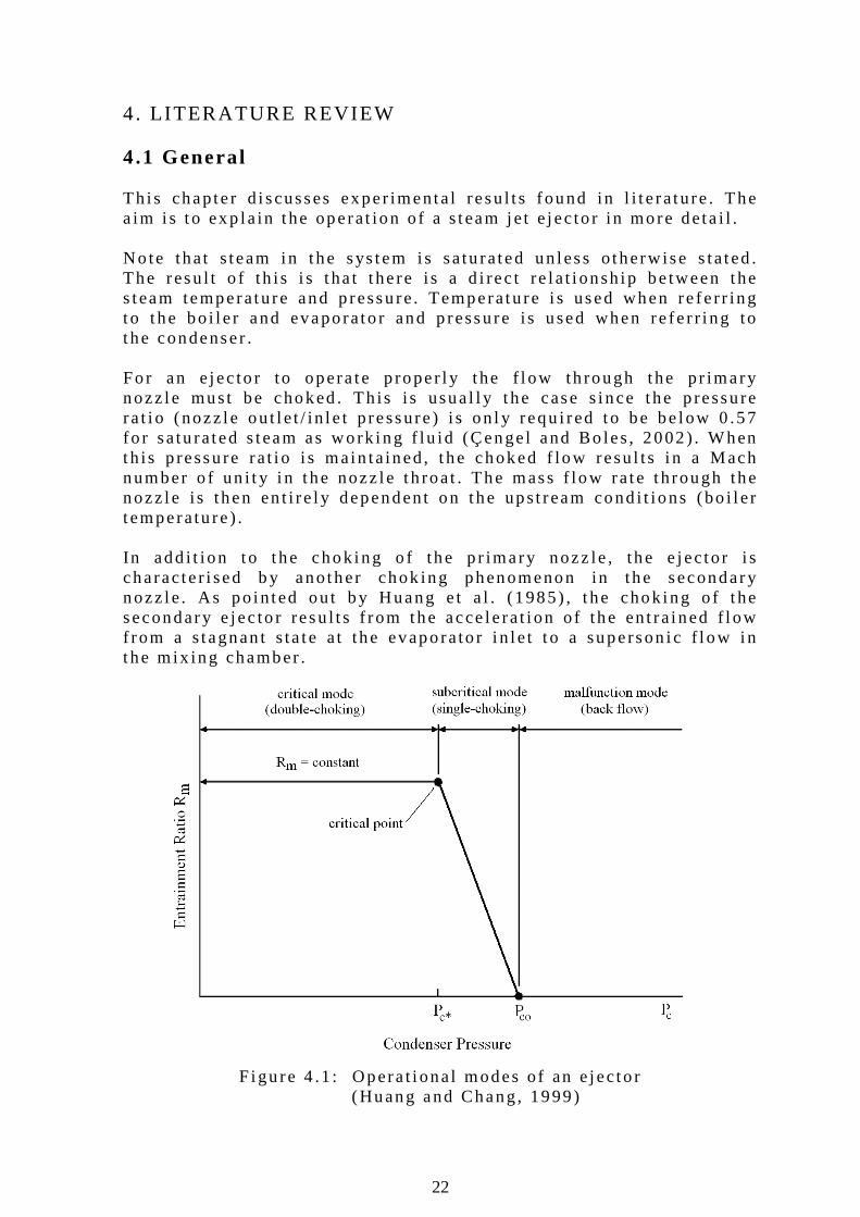
4. LITERATURE REVIEW 4.1 General Th i s chapte r d i scusses exper imenta l resu l t s found in l i t e ra tu re . The a im i s t o exp la in t he opera t ion o f a s team je t e jec to r in more deta i l . No te that s team in t he sys tem i s sa tu ra ted un less o therw ise s ta ted . The resu l t o f th is i s t ha t t he re i s a d i rec t re la t i onsh ip be tween the s team temperature and p ressu re . Temperatu re i s used when re fe r r ing to t he bo i l e r and evaporato r and p ressu re i s used when re fe r r i ng to t he condenser . Fo r an e jec to r to opera te p roper l y t he f l ow th rough the pr imary nozz le must be choked . Th is i s usua l l y t he case s ince the p ressu re ra t i o (nozz le ou t l e t / in l e t p ressure ) i s on l y requ i red to be be low 0 .57 fo r sa tu ra ted s team as work ing f lu id (Çengel and Bo les , 2002) . When th is p ressu re ra t i o i s main ta ined, t he choked f low resu l ts i n a Mach number o f un i t y i n t he nozz le t h roat . The mass f low ra te th rough the nozz le i s then en t i re l y dependent on the ups t ream cond i t ions (bo i l e r t emperatu re ) . In add i t ion to t he chok ing o f the p r imary nozz le , the e jec to r i s characte r i sed b y another chok ing phenomenon in the secondary nozz le . As po in ted ou t by Huang e t a l . (1985) , t he chok ing o f t he secondary e jec to r resu l t s f rom the acce le ra t i on o f the en t ra ined f l ow f rom a s tagnan t s ta te a t the evaporato r i n l e t t o a superson i c f l ow i n t he m ix ing chamber .
F igu re 4 .1 : Opera t i ona l modes o f an e jec to r (Huang and Chang, 1999)
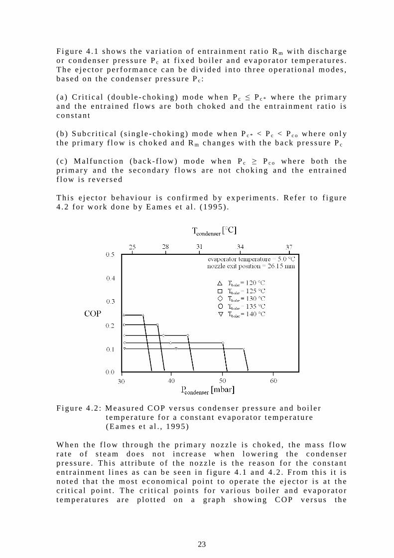
23
F igu re 4 .1 shows the va r ia t ion o f en t ra inmen t ra t io Rm w i th d ischarge o r condenser p ressu re Pc a t f i x ed bo i le r and evaporato r tempera tu res . The e jec to r pe r fo rmance can be d i v ided i n to th ree opera t iona l modes , based on the condenser p ressure Pc : (a ) C r i t i ca l (doub le -chok ing) mode when Pc ≤ Pc * where the p r imary and the en t ra ined f l ows a re bo th choked and the en t ra inment ra t i o is cons tan t
(b ) Subcr i t i ca l (s ing le -chok ing) mode when Pc * < Pc < Pc o where on l y t he pr imary f l ow is choked and Rm changes w i th t he back p ressure Pc ( c ) Ma l func t ion (back - f low) mode when Pc ≥ Pc o where bo th the p r imary and the secondary f l ows a re no t chok ing and the en t ra ined f l ow i s reversed Th i s e jec to r behav iou r i s con f i rmed b y ex per imen ts . Re fe r t o f i gu re 4 .2 fo r work done b y Eames e t a l . (1995) . F igu re 4 .2 : Measured COP versus condenser p ressu re and bo i le r t emperatu re fo r a cons tan t evaporator t emperatu re (Eames e t a l . , 1995) When the f low th rough the p r imary nozz le i s choked, the mass f low ra te o f s team does no t inc rease when l ower ing the condenser p ressure . Th is a t t r i bu te o f t he nozz le i s t he reason fo r the cons tan t en t ra inment l i nes as can be seen in f igu re 4 .1 and 4 .2 . From th i s i t is no ted that t he most economica l po in t t o opera te the e jec to r i s a t t he c r i t i ca l po in t . The c r i t i ca l po in ts fo r va r i ous bo i l e r and evaporato r t emperatu res a re p lo t t ed on a g raph showing COP versus the
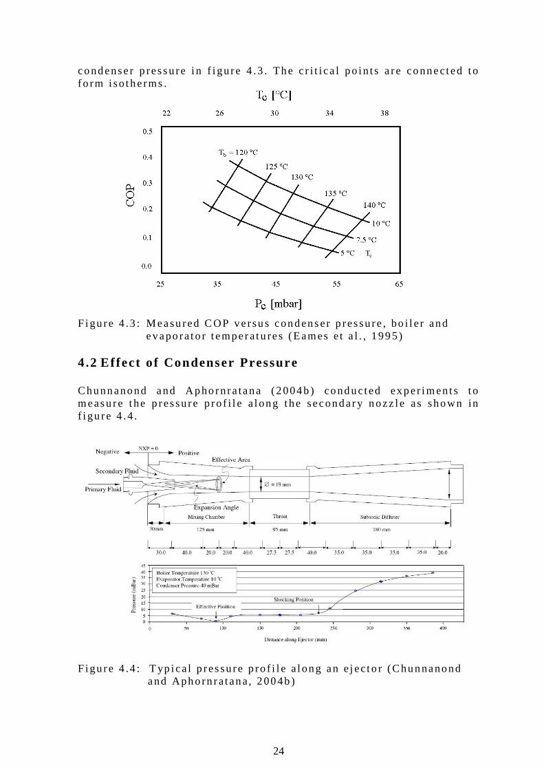
24
condenser p ressu re i n f i gure 4 .3 . The c r i t i ca l po in ts a re connected to fo rm i so therms . F igu re 4 .3 : Measured COP versus condenser p ressu re , bo i l e r and evaporato r t emperatu res (Eames e t a l . , 1995) 4.2 Effect of Condenser Pressure Chunnanond and Aphornra tana (2004b) conducted exper iments t o measure the p ressure p ro f i l e a long the secondary nozz le as shown in f i gu re 4 .4 . F igu re 4 .4 : T yp i ca l p ressu re p ro f i l e a long an e jec to r (Chunnanond and Aphorn ra tana, 2004b)
25
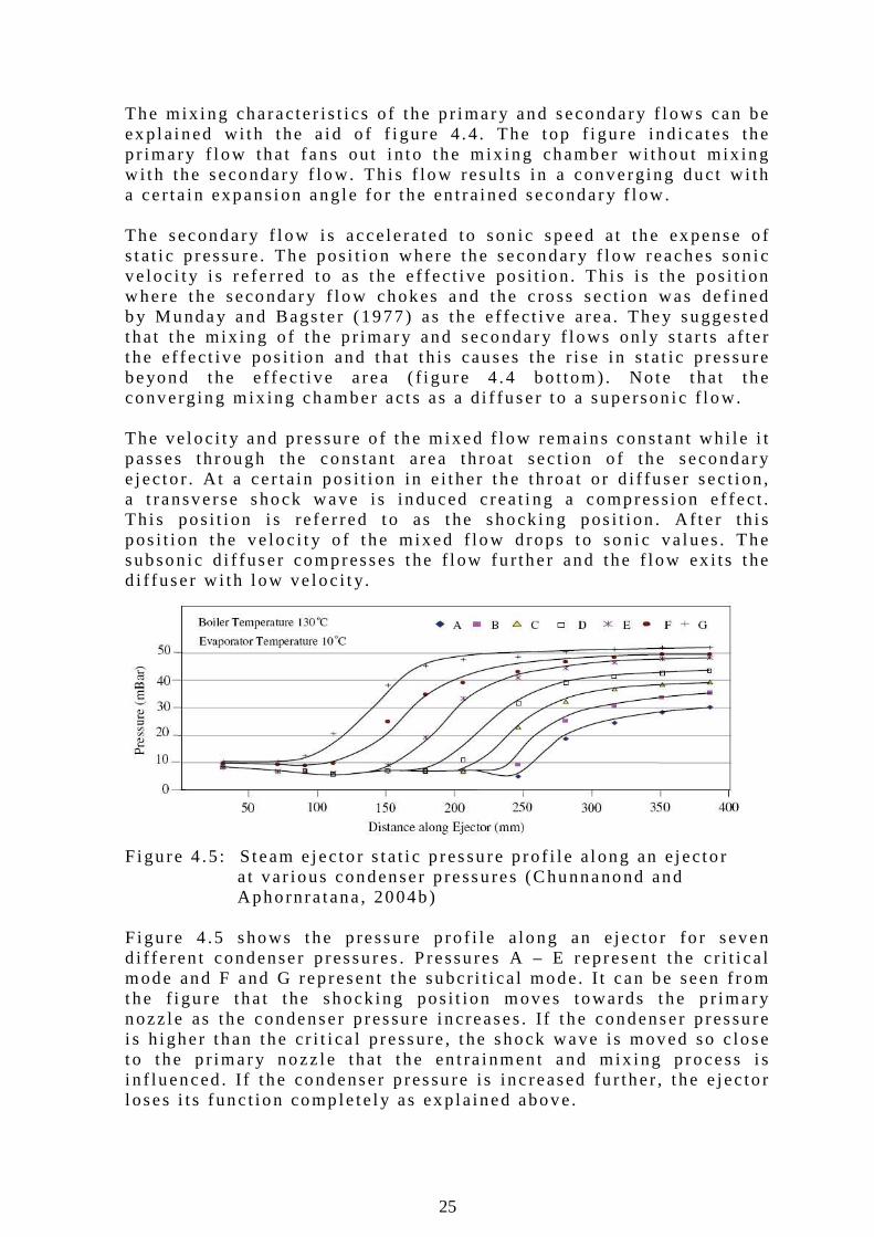
The mix ing characte r i s t i cs o f the p r imary and secondary f l ows can be ex p la ined w i th t he a id o f f i gure 4 .4 . The top f i gu re ind i ca tes the p r imary f l ow that fans ou t i n to t he m ix ing chamber w i thout m ix ing w i th the secondary f low. Th i s f low resu l t s in a converg ing duct w i th a ce r ta in expans ion ang le fo r the en t ra ined secondary f l ow . The secondary f l ow i s acce le ra ted to son ic speed a t the ex pense o f s ta t i c p ressu re . The pos i t ion where the secondary f l ow reaches son i c ve loc i t y i s re fe r red to as the e f fec t i ve pos i t i on . Th i s i s the pos i t i on where the secondary f l ow chokes and the c ross sect i on was de f ined b y Munday and Bags te r (1977) as the e f fec t i ve a rea. They sugges ted that t he mix ing o f t he p r imary and secondary f l ows on l y s tar ts a f t e r t he e f fec t i ve pos i t ion and that t h i s causes the r i se in s ta t i c p ressu re beyond the e f fec t i ve a rea ( f i gu re 4 .4 bo t tom) . No te that the converg ing mix ing chamber ac t s as a d i f fuser t o a superson i c f l ow. The ve loc i t y and pressu re o f the m ixed f low remains cons tan t wh i l e i t passes th rough the cons tan t a rea th roat sec t ion o f the secondary e jec to r . A t a ce r ta in pos i t i on in e i t her t he th roa t o r d i f fuser sec t ion , a t ransverse shock wave is induced c rea t i ng a compress ion e f fec t . Th i s pos i t i on i s re fe r red to as the shock ing pos i t i on . A f te r th i s pos i t i on the ve loc i t y o f t he mixed f low d rops to son i c va lues . The subson ic d i f fuser compresses the f l ow fu r the r and the f low ex i ts t he d i f fuser w i th l ow ve loc i t y.
F igu re 4 .5 : S team e jec to r s ta t i c p ressu re p ro f i l e a long an e jec to r
a t var ious condenser p ressu res (Chunnanond and Aphornra tana , 2004b) F igu re 4 .5 shows the p ressu re p ro f i l e a long an e jec to r fo r seven d i f fe ren t condenser p ressu res . P ressu res A – E represent the c r i t i ca l mode and F and G rep resent t he subcr i t i ca l mode. I t can be seen f rom the f i gu re tha t the shock ing pos i t ion moves towards the p r imary nozz le as the condenser p ressu re i ncreases . I f t he condenser p ressu re i s h igher t han the cr i t i ca l p ressure , t he shock wave is moved so c lose to the p r imary nozz le that t he en t ra inmen t and mix ing p rocess i s i n f luenced . I f t he condenser p ressu re i s inc reased fu r the r , t he e jec to r l oses i t s func t ion comp le te l y as ex p la ined above.
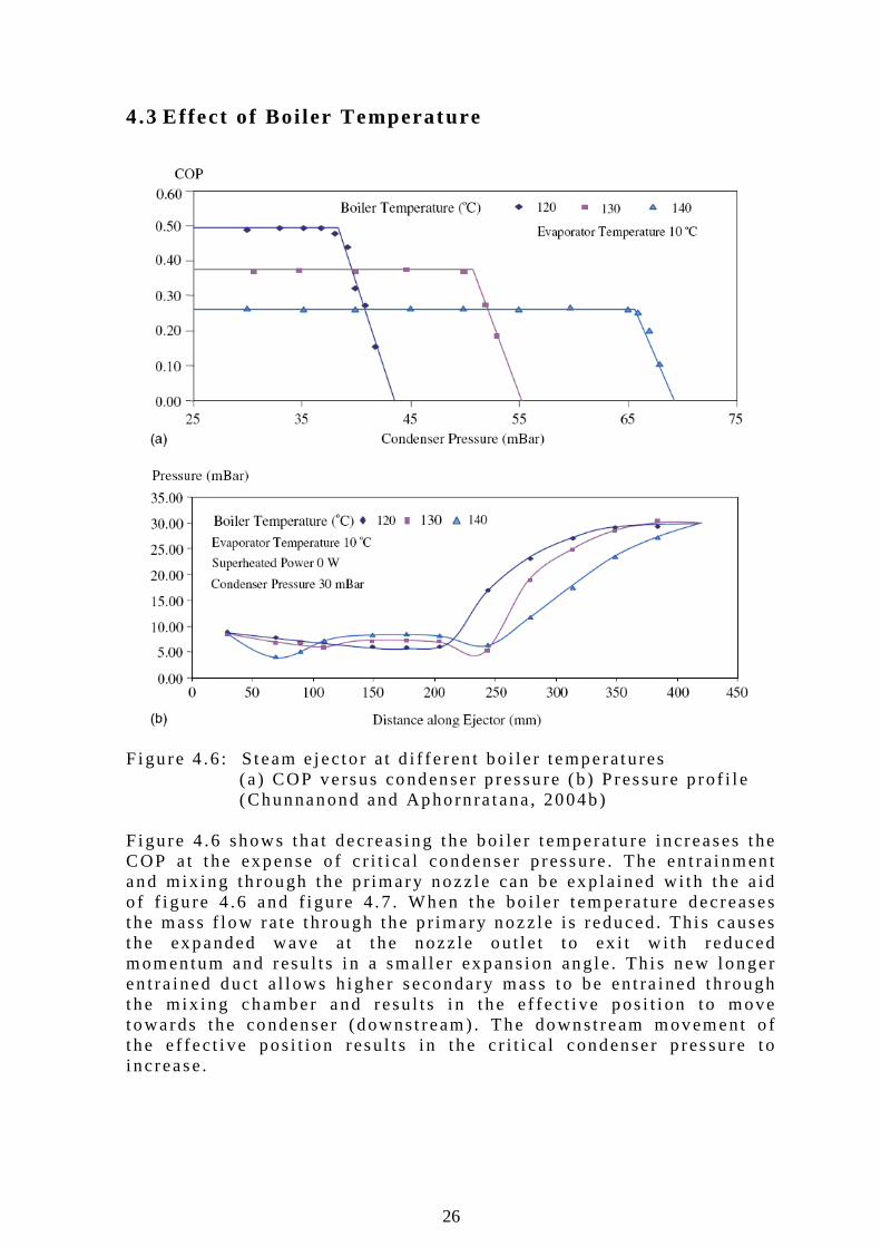
26
4.3 Effect of Boi ler Temperature F igu re 4 .6 : S team e jec to r a t d i f fe ren t bo i l e r temperatures (a ) COP versus condenser p ressu re (b ) P ressu re p ro f i l e (Chunnanond and Aphorn ra tana , 2004b) F igu re 4 .6 shows tha t dec reas ing the bo i le r t emperatu re i ncreases the COP a t t he expense o f c r i t i ca l condenser p ressure . The en t ra inmen t and mix ing th rough the p r imary nozz le can be exp la ined w i th the a id o f f i gu re 4 .6 and f i gu re 4 .7 . When the bo i l e r t empera ture dec reases the mass f low ra te th rough the p r imary nozz le i s reduced. Th i s causes the expanded wave a t t he nozz le ou t l e t to ex i t w i t h reduced momentum and resu l ts i n a smal l e r expans ion ang le . Th i s new longer en t ra ined duct a l l ows h igher secondary mass to be en t ra ined th rough the mix ing chamber and resu l ts i n t he e f fec t i ve pos i t i on to move towards the condenser (downst ream) . The downst ream movement o f t he e f fec t i ve pos i t i on resu l t s in the c r i t i ca l condenser p ressu re to i ncrease.
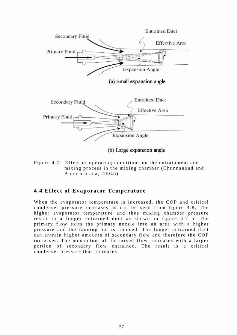
27
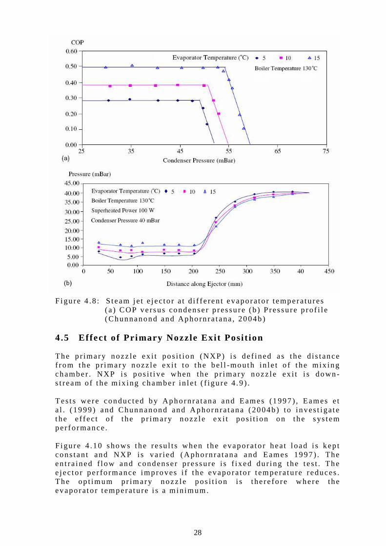
F igu re 4 .7 : E f fec t o f opera t ing cond i t i ons on the en t ra inment and m ix ing p rocess in t he mix ing chamber (Chunnanond and Aphornra tana , 2004b) 4.4 Ef fect of Evaporator Temperature When the evaporato r t emperatu re i s inc reased, t he COP and c r i t i ca l condenser p ressu re i ncreases as can be seen f rom f i gure 4 .8 . The h igher evaporator t emperature and thus mix ing chamber p ressu re resu l t in a l onger en t ra ined duc t as shown in f i gu re 4 .7 a . The p r imary f l ow ex i ts t he p r imary nozz le in to an a rea w i th a h igher p ressure and the fann ing ou t i s reduced . The l onger en t ra ined duct can en t ra in h igher amounts o f secondary f l ow and the re fo re the COP increases . The momentum o f the m ixed f low i ncreases w i th a l a rger po r t i on o f secondary f l ow ent ra ined . The resu l t i s a c r i t i ca l condenser p ressu re that i ncreases .
28
F igu re 4 .8 : S team je t e jec to r a t d i f fe ren t evaporato r temperatu res (a ) COP versus condenser p ressu re (b ) P ressu re p ro f i l e (Chunnanond and Aphorn ra tana , 2004b) 4.5 Effect of Pr imary Nozzle Exi t Posi t ion The p r imary nozz le ex i t pos i t ion (NXP) i s de f i ned as the d is tance f rom the p r imary nozz le ex i t to t he be l l -mouth in le t o f t he mix ing chamber . NXP i s pos i t i ve when the p r imary nozz le ex i t i s down-s t ream o f t he m ix ing chamber in le t ( f igu re 4 .9 ) . Tes ts were conducted b y Aphornra tana and Eames (1997) , Eames e t a l . (1999) and Chunnanond and Aphorn ra tana (2004b) to inves t i ga te the e f fec t o f t he p r imary nozz le ex i t pos i t i on on the s ys tem per fo rmance. F igu re 4 .10 shows the resu l ts when the evaporato r heat l oad i s kep t cons tan t and NXP is va r ied (Aphorn ra tana and Eames 1997) . The en t ra ined f l ow and condenser p ressure i s f i xed du r i ng the tes t . The e jec to r pe r fo rmance improves i f the evaporato r t emperatu re reduces . The op t imum pr imary nozz le pos i t ion i s t he re fo re where the evaporato r t emperatu re i s a min imum.
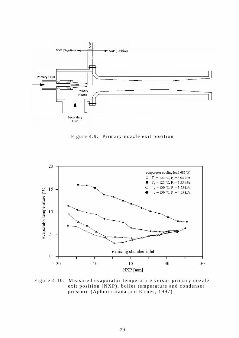
29
F igu re 4 .9 : P r imary nozz le ex i t pos i t ion F igu re 4 .10 : Measured evaporato r tempera tu re ve rsus pr imary nozz le
ex i t pos i t ion (NXP) , bo i l e r t emperature and condenser p ressure (Aphorn ra tana and Eames, 1997)
30
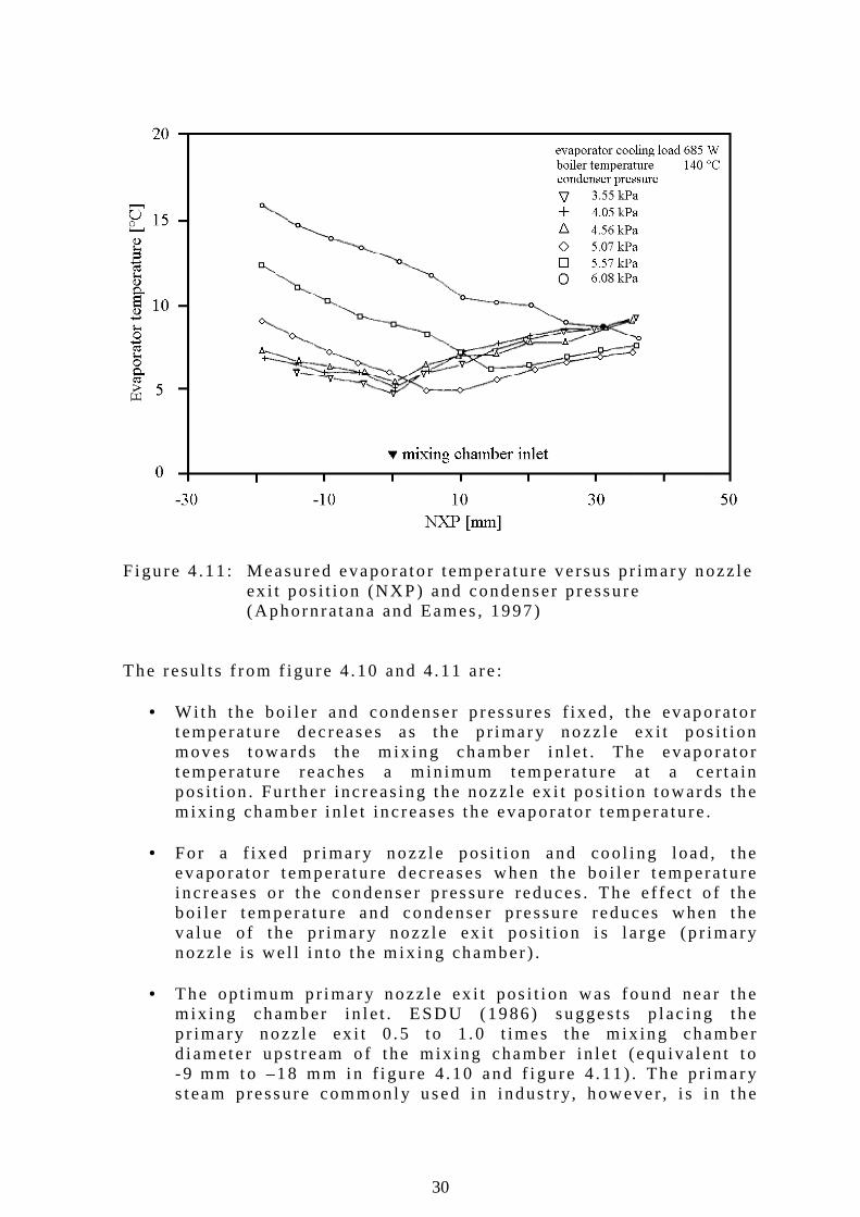
F igu re 4 .11 : Measured evaporato r tempera tu re ve rsus pr imary nozz le
ex i t pos i t i on (NXP) and condenser p ressure (Aphorn ra tana and Eames , 1997)
The resu l ts f rom f igu re 4 .10 and 4 .11 a re :
• With the bo i le r and condenser p ressures f i x ed , t he evaporato r t emperatu re dec reases as the p r imary nozz le ex i t pos i t i on moves towards the m ix ing chamber i n le t . The evaporato r t emperatu re reaches a min imum tempera tu re a t a ce r ta in pos i t i on . Fu r ther inc reas ing the nozz le ex i t pos i t ion towards the m ix ing chamber i n le t inc reases the evaporato r t empera ture .
• For a f i xed p r imary nozz le pos i t i on and coo l i ng load , the
evaporato r t emperatu re dec reases when the bo i l e r t empera tu re i ncreases or the condenser p ressu re reduces . The e f fec t o f the bo i le r t empera tu re and condenser p ressu re reduces when the va lue o f the pr imary nozz le ex i t pos i t ion i s l a rge (p r imary nozz le i s we l l i n to t he m ix ing chamber ) .
• The opt imum p r imary nozz le ex i t pos i t i on was found near the
m ix ing chamber in le t . ESDU (1986) sugges ts p lac ing the p r imary nozz le ex i t 0 .5 to 1 .0 t imes the m ix ing chamber d iamete r ups t ream o f the m ix ing chamber in le t (equ iva len t t o -9 mm to –18 mm in f i gu re 4 .10 and f i gu re 4 .11 ) . The pr imary s team pressure commonly used in indus t ry, however , i s i n t he
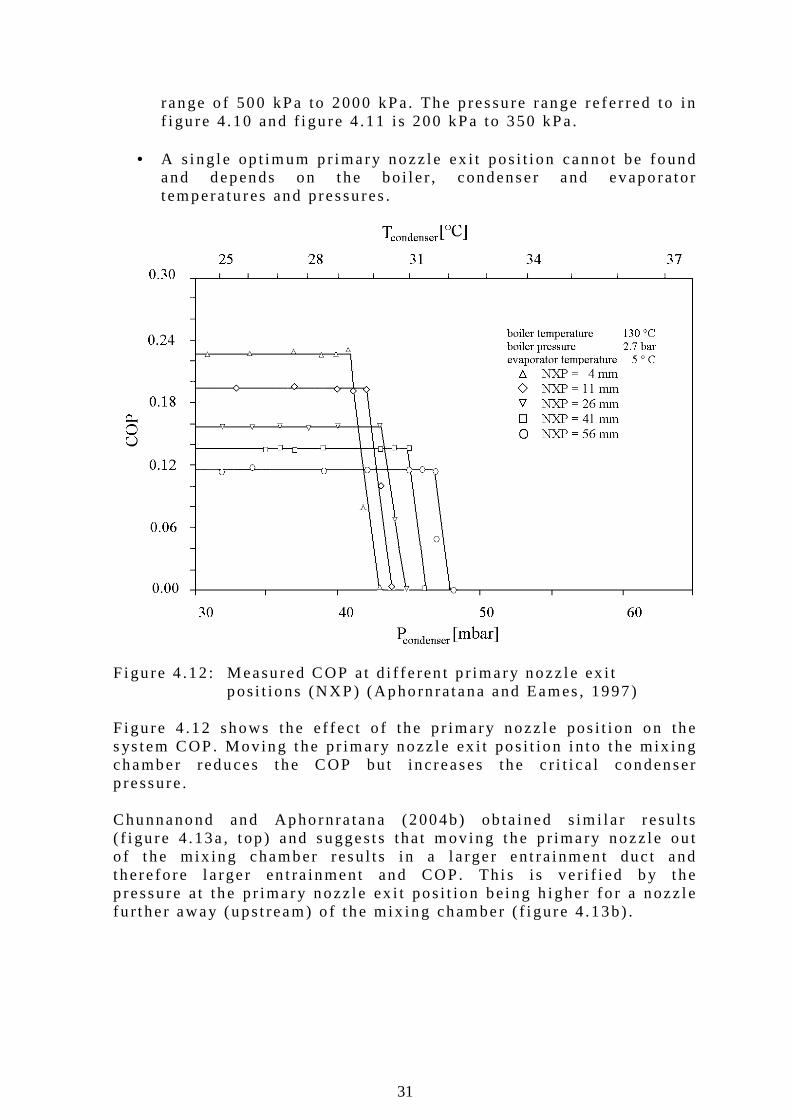
31
range o f 500 kPa to 2000 kPa. The p ressu re range re fe r red to in f i gu re 4 .10 and f i gu re 4 .11 i s 200 kPa to 350 kPa .
• A s ing le op t imum p r imary nozz le ex i t pos i t i on cannot be found
and depends on the bo i l e r , condenser and evaporator t emperatu res and pressu res .
F igu re 4 .12 : Measured COP at d i f fe ren t p r imary nozz le ex i t
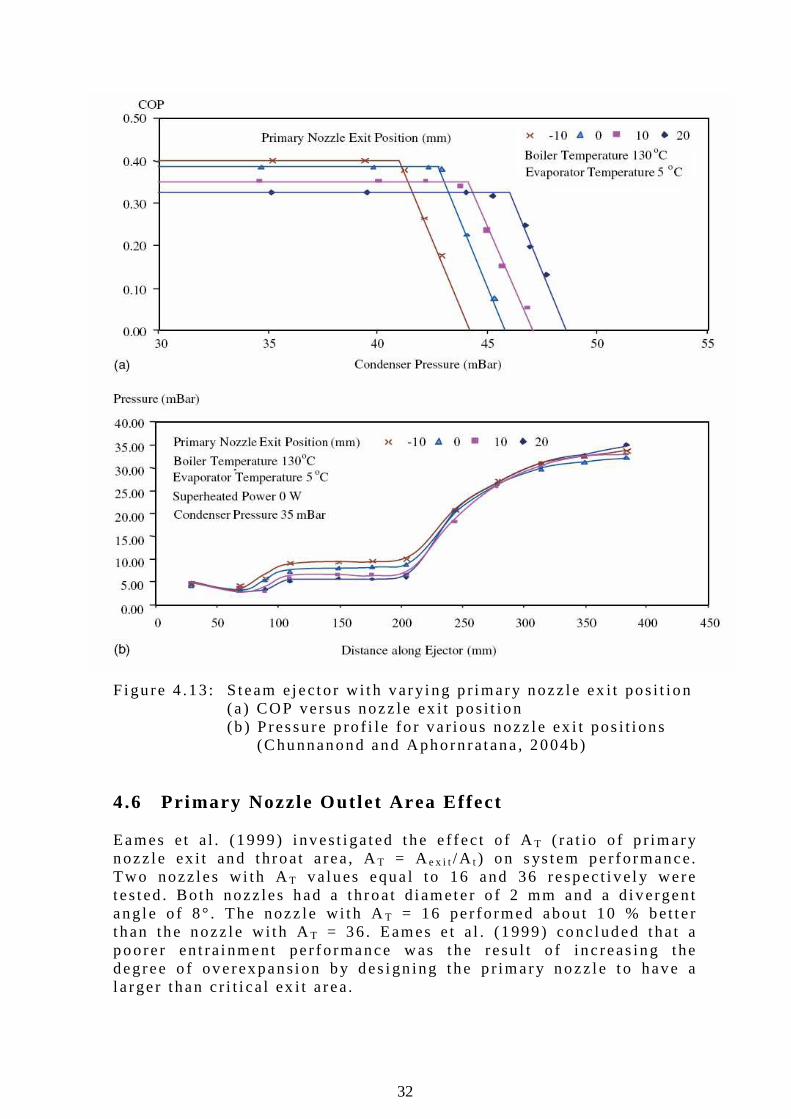
pos i t ions (NXP) (Aphorn ra tana and Eames , 1997) F igu re 4 .12 shows the e f fec t o f the p r imary nozz le pos i t i on on the s ys tem COP. Mov ing the pr imary nozz le ex i t pos i t ion i n to t he mix ing chamber reduces the COP but increases the c r i t i ca l condenser p ressure . Chunnanond and Aphornra tana (2004b) ob ta ined s im i l a r resu l ts ( f i gu re 4 .13a , t op ) and sugges ts that mov ing the p r imary nozz le ou t o f t he mix ing chamber resu l t s in a l a rger en t ra inmen t duc t and there fore l a rger en t ra inment and COP. Th i s i s ve r i f i ed by the p ressure a t the pr imary nozz le ex i t pos i t ion be ing h igher fo r a nozz le fu r the r away (ups t ream) o f t he mix ing chamber ( f i gure 4 .13b) .
32
F igu re 4 .13 : S team e jec tor w i th var y ing p r imary nozz le ex i t pos i t ion
(a ) COP versus nozz le ex i t pos i t ion (b ) P ressu re p ro f i le fo r va r i ous nozz le ex i t pos i t i ons (Chunnanond and Aphorn ra tana , 2004b)
4.6 Primary Nozzle Out le t Area Ef fect Eames e t a l . (1999) i nves t i ga ted the e f fec t o f AT ( ra t io o f p r imary nozz le ex i t and th roat a rea, AT = Ae x i t /A t ) on s ys tem per fo rmance. Two nozz les w i th AT va lues equa l to 16 and 36 respec t i ve l y were tes ted . Both nozz les had a th roat d iamete r o f 2 mm and a d i vergen t ang le o f 8° . The nozz le w i th AT = 16 per fo rmed about 10 % bet te r t han the nozz le w i th AT = 36 . Eames e t a l . (1999) conc luded tha t a poore r en t ra inment pe r fo rmance was the resu l t o f inc reas ing the degree o f overexpans ion by des ign ing the p r imary nozz le t o have a l a rger than c r i t i ca l ex i t a rea.
33
4.7 Primary Nozzle Throat Area A R i s de f ined as the p r imary nozz le t h roat a rea d iv ided b y the secondary nozz le th roat a rea. AR = A t /A 4 . Chunnanond and Aphornra tana (2004b) found that reduc ing AR ( reduc ing At and keep ing A4 cons tan t ) inc reases the COP a t t he expense o f t he c r i t i ca l condenser p ressure . A smal l e r p r imary nozz le th roat resu l t s i n a smal l e r mass o f p r imary s team that expands . Th i s resu l t s in h igher s ta t i c p ressu res a t the p r imary nozz le ou t l e t and the downs t ream movement o f the e f fec t i ve pos i t i on . Eames e t a l . (1999) ob ta ined s im i l a r resu l t s . In t he i r exper iments t he p r imary nozz le th roa t area was kep t cons tan t wh i l e the secondary nozz le t h roat a rea was va r ied . Lower ing AR , t he bo i l e r p ressu re cou ld be reduced w i thout chang ing the evaporato r t emperatu re o r c r i t i ca l condenser p ressure . A l t e rnat i ve l y l ower ing AR resu l t ed in inc reas ing the c r i t i ca l condenser p ressure w i thout a l t e r i ng the evaporato r t emperatu re o r bo i l e r p ressu re . In bo th cases the decreas ing o f AR were a t the expense o f the en t ra inmen t ra t io and the re fo re COP. 4.8 Superheat ing of Pr imary Steam Chunnanond and Aphornra tana (2004b) inves t i ga ted the e f fec t o f superhea t ing the pr imary s team. The s team f rom an 8 kW bo i l e r cou ld be superheated by add ing up to 180 W o f add i t iona l hea t to the p r imary s team in t he i r exper imenta l se tup . The i r resu l ts ind i ca ted that the superhea ted l eve l had ve ry l i t t l e impact on e i ther the COP o r c r i t i ca l condenser p ressure . Thus , acco rd ing to the recommendat i on o f ESDU (1986) , the superhea t i ng o f s team has no advan tage o ther t han to p revent t he damage o f the e jec to r caused by we t s team. 4.9 Operat ing Condi t ions In summary, when des ign ing a s team je t e jec to r , the c r i t i ca l conden-ser p ressu re can be inc reased by:
• i ncreas ing the p r imary nozz le t h roat o r decreas ing the secondary e jec to r th roat
• i ncreas ing the bo i le r t emperature • advanc ing the pr imary nozz le ex i t pos i t ion towards the mix ing
chamber in le t (up to a op t imum po in t where a f te r i t has the oppos i te e f fec t )
• i ncreas ing the evaporato r temperature The COP can be i nc reased b y:
• decreas ing the bo i l e r temperature and p ressure (up to a op t imum po in t fo r a spec i f i ed c r i t i ca l condenser p ressu re a f ter wh ich the COP fa l l s rap id l y)
• decreas ing the p r imary nozz le th roa t a rea
34
• advanc ing the p r imary nozz le ex i t pos i t i on towards the m ix ing chamber in le t
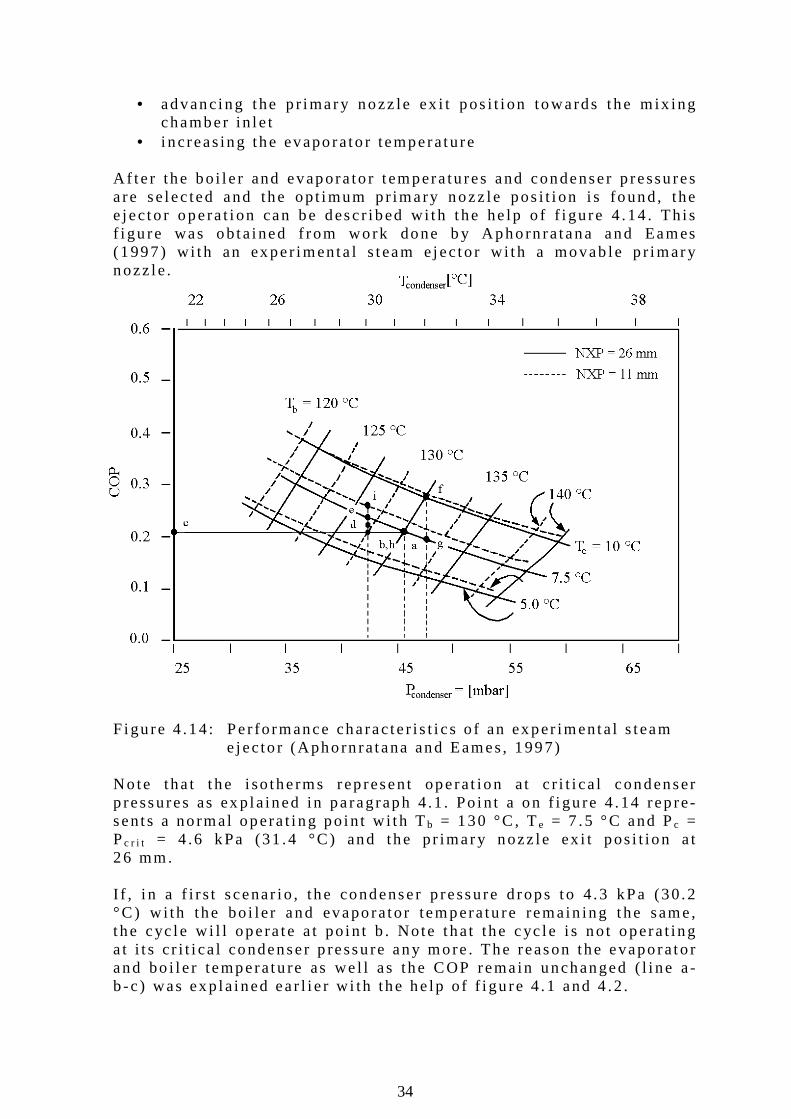
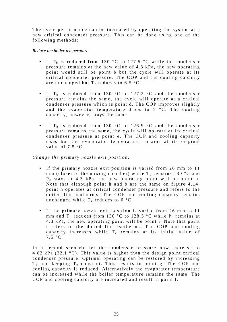
• i ncreas ing the evaporato r temperature A f te r the bo i l e r and evapora to r t empera tu res and condenser p ressu res a re se lec ted and the op t imum p r imary nozz le pos i t i on i s found, the e jec to r opera t i on can be desc r i bed w i th t he he lp o f f i gure 4 .14 . Th i s f i gu re was ob ta ined f rom work done b y Aphorn ra tana and Eames (1997) w i th an exper imenta l s team e jec to r w i th a movab le p r imary nozz le . F igu re 4 .14 : Per fo rmance characte r i s t i cs o f an exper imenta l s team e j ec to r (Aphorn ra tana and Eames, 1997) No te tha t t he i so therms rep resent opera t ion a t c r i t i ca l condenser p ressures as ex p la ined in pa ragraph 4 .1 . Po in t a on f i gu re 4 .14 rep re-sents a no rmal opera t i ng po in t w i th Tb = 130 °C , Te = 7 .5 °C and Pc = Pc r i t = 4 .6 kPa (31 .4 °C) and the pr imary nozz le ex i t pos i t ion a t 26 mm. I f , i n a f i r s t scenar io , the condenser p ressure d rops to 4 .3 kPa (30 .2 °C) w i th the bo i le r and evaporator tempera tu re remain ing the same, t he cyc le w i l l opera te a t po in t b . Note that the cyc le i s no t opera t ing a t i t s c r i t i ca l condenser p ressu re any more . The reason the evaporato r and bo i l e r temperatu re as we l l as the COP rema in unchanged ( l i ne a -b -c ) was exp la ined ear l i e r w i th the he lp o f f i gu re 4 .1 and 4 .2 .
35
The cyc le per fo rmance can be i nc reased by opera t ing the s ys tem at a new c r i t i ca l condenser p ressu re . Th is can be done us ing one o f t he fo l lowing methods : Reduce the boiler temperature
• I f T b i s reduced f rom 130 °C to 127.5 °C wh i l e the condenser
p ressure remains a t t he new va lue o f 4 .3 kPa , t he new opera t i ng po in t wou ld s t i l l be po in t b bu t t he cyc le w i l l opera te a t i t s c r i t i ca l condenser p ressure . The COP and the coo l i ng capac i t y a re unchanged bu t Te reduces to 6 .5 °C .
• I f T b i s reduced f rom 130 °C to 127 .2 °C and the condenser
p ressure remains the same, the cyc le w i l l opera te a t a c r i t i ca l condenser p ressu re wh ich i s po in t d . The COP improves s l i gh t l y and the evaporator temperature d rops to 7 °C . The coo l i ng capac i t y, however , s tays the same.
• I f T b i s reduced f rom 130 °C to 126 .9 °C and the condenser
p ressure remains the same, the cyc le w i l l opera te a t i t s c r i t i ca l condenser p ressure a t po in t e . The COP and coo l i ng capac i t y r i ses bu t t he evaporato r t emperatu re remains a t i t s o r i g inal va lue o f 7 .5 °C .
Change the p r imary nozz le ex i t pos i t ion .
• I f t he p r imary nozz le ex i t pos i t ion i s va r i ed f rom 26 mm to 11 mm (c loser to t he m ix ing chamber ) wh i l e Tb rema ins 130 °C and Pc s tays a t 4 .3 kPa , t he new operat ing po in t w i l l be po in t h . No te tha t a l though po in t h and b a re the same on f i gure 4 .14 , po in t h opera tes a t c r i t i ca l condenser p ressure and re fe rs t o t he do t ted l ine i so therms. The COP and coo l i ng capac i t y r emains unchanged wh i l e Te reduces to 6 °C.
• I f t he p r imary nozz le ex i t pos i t ion i s va r i ed f rom 26 mm to 11
mm and Tb reduces f rom 130 °C to 128 .5 °C wh i l e Pc remains a t 4 .3 kPa , the new operat ing po in t w i l l be po in t i . Note tha t po in t i re fe rs to t he do t ted l i ne i so therms . The COP and coo l i ng capac i t y i nc reases wh i l e Te remains a t i t s in i t i a l va lue o f 7 .5 °C.
In a second scenar io l e t the condenser p ressu re now inc rease to 4 .82 kPa (32 .1 °C) . Th is va lue i s h igher t han the des ign po in t c r i t i ca l condenser p ressu re . Op t imal opera t i ng can be res to red b y i nc reas ing T b and keep ing Te cons tan t . Th i s resu l t s in po in t g . The COP and coo l i ng capac i t y i s reduced . A l t e rnat i ve l y t he evaporator t emperatu re can be inc reased wh i l e t he bo i l e r t emperatu re rema ins the same. The COP and coo l i ng capac i t y a re i ncreased and resu l t i n po in t f .
36
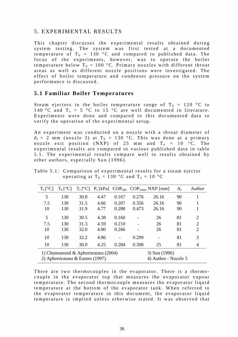
5. EXPERIMENTAL RESULTS Th i s chap te r d iscusses the exper imen ta l resu l ts ob ta ined du r ing s ys tem tes t ing . The s ys tem was f i r s t t es ted a t a documented temperatu re o f Tb = 130 °C and compared to pub l i shed data . The focus o f t he exper iments , however , was to opera te the bo i l e r t emperatu re be low Tb = 100 °C. P r imary nozz les w i th d i f fe ren t th roat a reas as wel l as d i f fe ren t nozz le pos i t ions were inves t i ga ted . The e f fec t o f bo i l e r t empera tu re and condenser p ressu re on the sys tem per fo rmance is d i scussed. 5.1 Fami l iar Boi ler Temperatures S team e jec tors in t he bo i l e r t emperatu re range o f Tb = 120 °C to 140 °C and Te = 5 °C to 15 °C are we l l documented in l i t e ra tu re . Ex per imen ts were done and compared to th is documen ted data to ve r i f y t he opera t ion o f t he exper imenta l se tup . An exper iment was conducted on a nozz le w i th a th roa t d iamete r o f d t = 2 mm (nozz le 3 ) a t Tb = 130 °C . Th is was done a t a p r imary nozz le ex i t pos i t ion (NXP) o f 25 mm and Te = 10 °C. The ex per imenta l resu l ts a re compared to va r i ous pub l i shed da ta i n t ab le 5 .1 . The exper imen ta l resu l ts compare wel l to resu l ts ob ta ined b y o ther au tho rs , espec ia l l y Sun (1996) . Tab le 5 .1 : Compar i son o f exper imenta l resu l ts fo r a s team e jec tor
opera t i ng a t Tb = 130 °C and Te = 10 °C
Te [°C] Tb [°C] Tc [°C] Pc [kPa] COPelec COPwater NXP [mm] At Author
5 130 30.8 4.47 0.167 0.276 26.16 90 1 7.5 130 31.5 4.66 0.207 0.356 26.16 90 1
10 130 31.9 4.77 0.288 0.473 26.16 90 1
5 130 30.5 4.38 0.160 - 26 81 2 7.5 130 31.3 4.59 0.210 - 26 81 2
10 130 32.0 4.80 0.266 - 26 81 2
10 130 32.2 4.86 - 0.299 - 81 3
10 130 30.0 4.25 0.284 0.308 25 81 4
1) Chunnanond & Aphornratana (2004) 3) Sun (1996)
2) Aphornratana & Eames (1997) 4) Author - Nozzle 3
There a re two the rmocoup les in t he evaporato r . There i s a t hermo-coup le in the evaporato r top that measures the evaporato r vapour t emperatu re . The second thermocoup le measures the evaporato r l i qu id t emperatu re a t t he bo t tom o f the evaporato r t ank . When re fe r red to t he evapora to r t emperatu re i n th is document , t he evaporato r l i qu id t emperatu re i s imp l ied un less o therwise s ta ted . I t was observed that
37
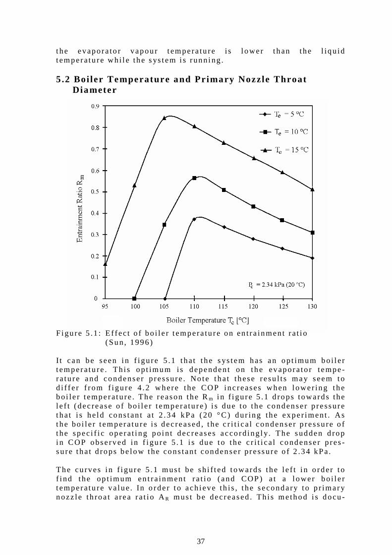
the evapora to r vapour t empera tu re i s l ower t han the l iqu id t emperatu re wh i l e the s ys tem i s runn ing . 5.2 Boi ler Temperature and Pr imary Nozzle Throat Diameter Figu re 5 .1 : E f fec t o f bo i l e r t empera tu re on en t ra inment ra t i o (Sun, 1996) I t can be seen i n f i gu re 5 .1 that t he s ys tem has an op t imum bo i l e r t emperatu re . Th is op t imum is dependent on the evapora to r tempe- ra tu re and condenser p ressure . No te that these resu l ts may seem to d i f fe r f rom f i gu re 4 .2 where the COP inc reases when l ower ing the bo i le r t emperatu re . The reason the Rm i n f i gu re 5 .1 d rops towards the l e f t (dec rease o f bo i l e r t emperatu re ) i s due to the condenser p ressure that i s he ld cons tan t a t 2 .34 kPa (20 °C) dur ing the exper iment . As the bo i l e r t empera tu re i s dec reased , the c r i t i ca l condenser p ressu re o f t he spec i f i c opera t i ng po in t dec reases acco rd ing l y. The sudden d rop i n COP observed in f i gu re 5 .1 i s due to the c r i t i ca l condenser p res -su re that d rops be low the cons tan t condenser p ressure o f 2 .34 kPa. The cu rves i n f i gure 5 .1 mus t be sh i f t ed towards the l e f t i n o rder t o f i nd the op t imum en t ra inment ra t i o (and COP) a t a l ower bo i l e r t emperatu re va lue. In o rder t o ach ieve th is , t he secondary to p r imary nozz le th roa t a rea ra t i o AR mus t be decreased . Th i s method i s docu -
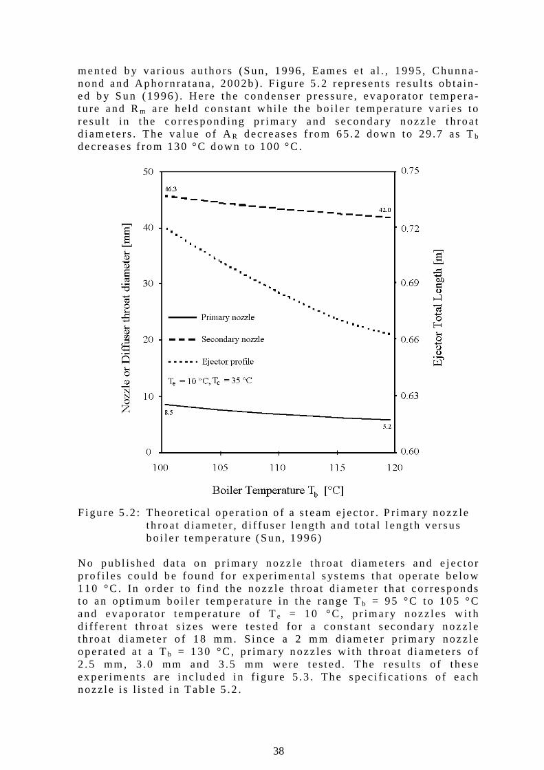
38
mented b y va r i ous au tho rs (Sun , 1996 , Eames e t a l . , 1995, Chunna-nond and Aphorn ra tana, 2002b) . F igu re 5 .2 represents resu l t s ob ta in -ed b y Sun (1996) . Here the condenser p ressu re , evapora to r t empera -tu re and Rm a re he ld cons tan t wh i l e the bo i l e r temperatu re va r i es to resu l t in t he co r respond ing p r imary and secondary nozz le t h roat d iamete rs . The va lue o f AR decreases f rom 65.2 down to 29 .7 as Tb dec reases f rom 130 °C down to 100 °C. F igu re 5 .2 : Theoret i ca l opera t ion o f a s team e jec to r . P r imary nozz le t h roat d iamete r , d i f f user l ength and to ta l l ength ve rsus bo i le r t empera tu re (Sun, 1996) No pub l i shed data on p r imary nozz le t h roa t d iamete rs and e jec to r p ro f i l es cou ld be found fo r exper imen ta l sys tems that opera te be low 110 °C. In o rder to f i nd the nozz le th roat d iameter t ha t co r responds to an op t imum bo i le r t emperatu re i n the range Tb = 95 °C to 105 °C and evapora to r t empera tu re o f Te = 10 °C, p r imary nozz les w i th d i f fe ren t t h roat s izes were tes ted fo r a cons tan t secondary nozz le t h roat d iamete r o f 18 mm. S ince a 2 mm d iamete r p r imary nozz le opera ted a t a Tb = 130 °C , p r imary n ozz les w i th th roat d iamete rs o f 2 .5 mm, 3 .0 mm and 3 .5 mm were tes ted . The resu l ts o f these ex per iments a re inc luded in f i gu re 5 .3 . The spec i f i ca t ions o f each nozz le i s l i s ted i n Tab le 5 .2 .
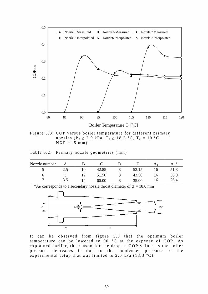
39
0.0
0.1
0.2
0.3
0.4
0.5
80 85 90 95 100 105 110 115 120
Boiler Temperature Tb [°C]
CO
Pele
cNozzle 5 Measured Nozzle 6 Measured Nozzle 7 Measured
Nozzle 5 Interpolated Nozzle6 Interpolated Nozzle 7 Interpolated
F igu re 5 .3 : COP versus bo i l e r t emperatu re fo r d i f fe ren t p r imary
nozz les (Pc ≥ 2 .0 kPa , Tc ≥ 18 .3 °C , Te = 10 °C , NXP = -5 mm)
Tab le 5 .2 : P r imary nozz le geomet r ies (mm)
Nozzle number A B C D E AT AR* 5 2.5 10 42.85 8 52.15 16 51.8 6 3 12 51.50 8 43.50 16 36.0 7 3.5 14 60.00 8 35.00 16 26.4
*AR corresponds to a secondary nozzle throat diameter of dt = 18.0 mm I t can be observed f rom f i gu re 5 .3 tha t t he op t imum bo i l e r t emperatu re can be lowered to 90 °C a t t he expense o f COP. As ex p la ined ear l i e r , the reason fo r the drop i n COP va lues as the bo i l e r p ressure dec reases i s due to the condenser p ressu re o f t he ex per imenta l se tup that was l im i ted to 2 .0 kPa (18 .3 °C) .
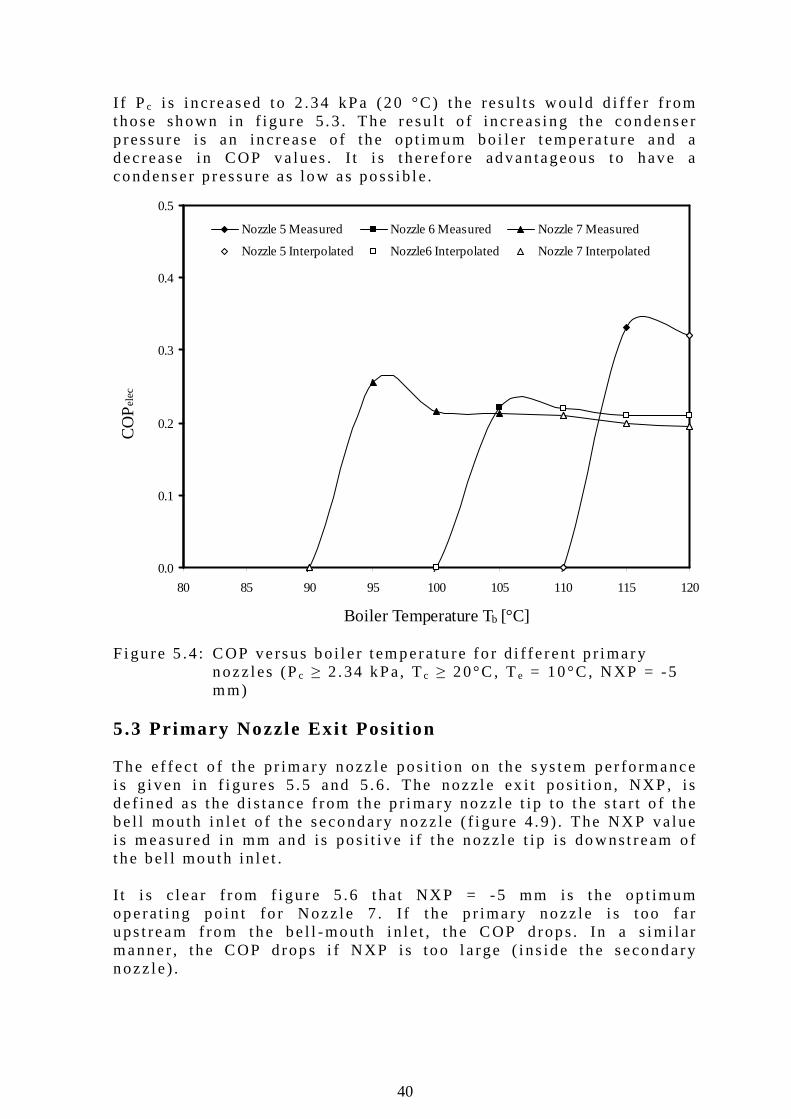
40
0.0
0.1
0.2
0.3
0.4
0.5
80 85 90 95 100 105 110 115 120
Boiler Temperature Tb [°C]
CO
Pele
c
Nozzle 5 Measured Nozzle 6 Measured Nozzle 7 Measured
Nozzle 5 Interpolated Nozzle6 Interpolated Nozzle 7 Interpolated
I f P c i s i ncreased to 2 .34 kPa (20 °C) t he resu l ts wou ld d i f fe r f rom those shown in f igu re 5 .3 . The resu l t o f inc reas ing the condenser p ressure i s an increase o f the op t imum bo i l e r t empera tu re and a dec rease in COP va lues . I t i s t here fo re advan tageous to have a condenser p ressu re as low as poss ib le . F igu re 5 .4 : COP versus bo i l e r t emperatu re fo r d i f fe ren t p r imary nozz les (Pc ≥ 2 .34 kPa, Tc ≥ 20°C , Te = 10°C , NXP = -5 mm) 5.3 Pr imary Nozzle Exi t Posi t ion The e f fec t o f the pr imary nozz le pos i t ion on the s ys tem per fo rmance i s g i ven i n f i gures 5 .5 and 5 .6 . The nozz le ex i t pos i t ion , NXP, i s de f i ned as the d is tance f rom the p r imary nozz le t ip to t he s ta r t o f the be l l mouth i n le t o f t he secondary nozz le ( f i gu re 4 .9 ) . The NXP va lue i s measured in mm and is pos i t i ve i f t he nozz le t ip i s downst ream o f t he be l l mouth in le t . I t i s c l ea r f rom f i gu re 5 .6 that NXP = -5 mm is t he op t imum operat i ng po in t fo r Nozz le 7 . I f t he p r imary nozz le i s t oo fa r ups t ream f rom the be l l -mouth i n le t , t he COP drops . In a s im i l ar manner , the COP d rops i f NXP is too l a rge ( i ns ide the secondary nozz le ) .
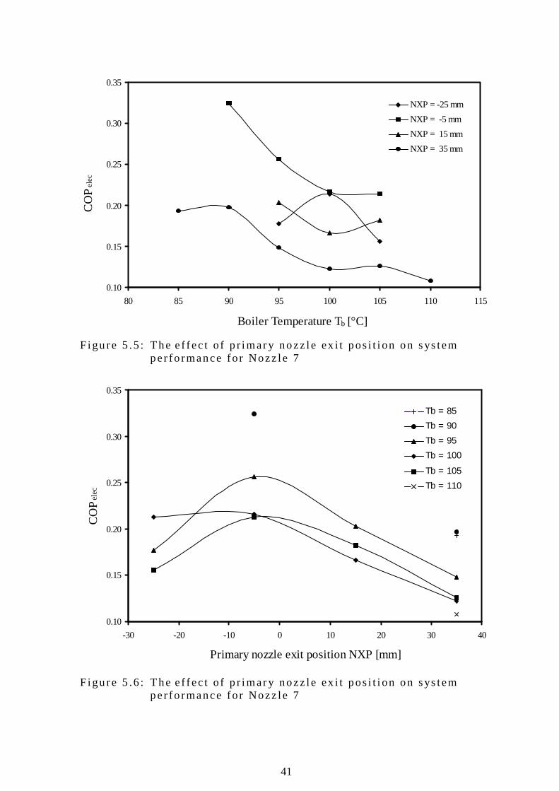
41
0.10
0.15
0.20
0.25
0.30
0.35
80 85 90 95 100 105 110 115
Boiler Temperature Tb [°C]
CO
Pele
c
NXP = -25 mm
NXP = -5 mm
NXP = 15 mm
NXP = 35 mm
0.10
0.15
0.20
0.25
0.30
0.35
-30 -20 -10 0 10 20 30 40
Primary nozzle exit position NXP [mm]
CO
Pele
c
Tb = 85
Tb = 90
Tb = 95
Tb = 100
Tb = 105
Tb = 110
F igu re 5 .5 : The e f fec t o f p r imary nozz le ex i t pos i t i on on sys tem pe r fo rmance fo r Nozz le 7 F igu re 5 .6 : The e f fec t o f p r imary nozz le ex i t pos i t i on on sys tem pe r fo rmance fo r Nozz le 7
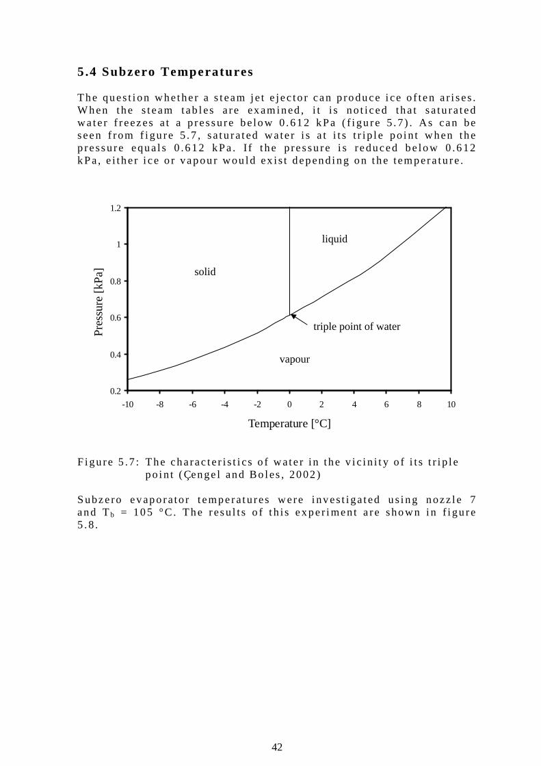
42
0.2
0.4
0.6
0.8
1
1.2
-10 -8 -6 -4 -2 0 2 4 6 8 10
Temperature [°C]
Pre
ssur
e [k
Pa]
5.4 Subzero Temperatures The ques t i on whether a s team je t e jec to r can p roduce i ce o f ten a r i ses . When the s team tab les a re examined , i t i s no t i ced tha t sa tu ra ted wa te r f reezes a t a p ressure be low 0 .612 kPa ( f i gu re 5 .7 ) . As can be seen f rom f i gu re 5 .7 , sa tu ra ted wa te r i s a t i t s t r ip l e po in t when the p ressure equa ls 0 .612 kPa . I f t he pressu re i s reduced be low 0 .612 kPa, e i the r i ce o r vapour wou ld ex is t depend ing on the tempera tu re .
F igu re 5 .7 : The charac ter i s t i cs o f wate r in the v i c i n i t y o f i t s t r i p l e po in t (Çenge l and Bo les , 2002) Subzero evaporator t emperatures were i nves t i ga ted us ing nozz le 7 and Tb = 105 °C. The resu l ts o f t h is exper iment a re shown in f i gu re 5 .8 .
vapour
solid
liquid
triple point of water
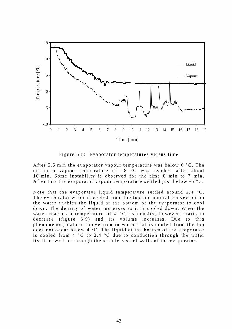
43
-10
-5
0
5
10
15
0 1 2 3 4 5 6 7 8 9 10 11 12 13 14 15 16 17 18 19
Time [min]
Te
mp
era
ture
[°C
]
Liquid
Vapour
F igu re 5 .8 : Evapora tor t emperatu res ve rsus t ime A f te r 5 .5 min the evaporato r vapour t empera tu re was be low 0 °C. The m in imum vapour t emperatu re o f –8 °C was reached a f te r about 10 min . Some ins tab i l i t y i s observed fo r t he t ime 8 min to 7 min . A f te r t h i s t he evaporato r vapour t empera tu re set t l ed jus t be low -5 °C. No te that the evaporato r l i qu id t emperatu re set t l ed a round 2 .4 °C . The evaporato r wate r i s coo led f rom the top and natu ra l convect ion in t he wa ter enab les the l i qu id a t t he bo t tom o f t he evapora tor to coo l down . The dens i t y o f wate r inc reases as i t i s coo led down . When the wa te r reaches a tempera tu re o f 4 °C i t s dens i t y, however , s ta r ts t o dec rease ( f i gu re 5 .9 ) and i t s vo lume inc reases . Due to th is phenomenon, natura l convect i on in wa te r tha t i s coo led f rom the top does no t occu r be low 4 °C . The l iqu id a t t he bo t tom o f t he evaporato r i s coo led f rom 4 °C to 2 .4 °C due to conduct i on th rough the wa ter i t se l f as wel l as t h rough the s ta in less s tee l wa l l s o f t he evaporato r .
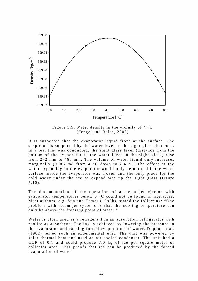
44
999.82
999.84
999.86
999.88
999.90
999.92
999.94
999.96
999.98
0.0 1.0 2.0 3.0 4.0 5.0 6.0 7.0 8.0
Temperature [°C]
Den
sity
[kg/
m3 ]
F igu re 5 .9 : Wate r dens i t y i n the v i c i n i t y o f 4 °C (Çenge l and Bo les , 2002) I t i s suspected that the evaporato r l i qu id f roze a t t he su r face . The susp i c ion i s suppor ted by the wate r l eve l i n the s igh t g lass that rose . In a t es t t ha t was conducted , t he s igh t g lass leve l (d is tance f rom the bo t tom o f the evaporato r t o t he wate r l eve l in t he s igh t g lass ) rose f rom 272 mm to 468 mm. The vo lume o f wate r l i qu id on l y i nc reases marg ina l l y (0 .002 %) f rom 4 °C down to 2 .4 °C. The e f fec t o f the wa te r expand ing in t he evapora to r wou ld on l y be no t i ced i f t he wate r su r face i ns ide the evaporato r was f rozen and the on l y p lace fo r the co ld wa ter under the i ce to expand was up the s igh t g lass ( f i gu re 5 .10 ) . The documenta t ion o f the opera t ion o f a s team je t e jec to r w i th evaporato r t emperatu res be low 5 °C cou ld no t be found i n l i t e ra tu re . Mos t au tho rs , e .g . Sun and Eames (1995b) , s ta ted the fo l l owing : “One p rob lem wi th s team- je t s ys tems i s tha t t he coo l ing tempera tu re can on l y be above the f reez ing po in t o f wate r . ” Wate r i s o f t en used as a re f r i ge ran t i n an adso rb t ion re f r ige ra to r w i th zeo l i t e as adso rbent . Coo l i ng i s ach ieved b y l ower ing the p ressu re in t he evapora to r and caus ing fo rced evaporat i on o f wate r . Dupont e t a l . (1982) t es ted such an exper imenta l un i t . The un i t was powered b y so la r t he rma l heat and used an a i r - coo led condenser . The un i t had a COP o f 0 .1 and cou ld p roduce 7 .0 kg o f i ce per square mete r o f co l l ec to r a rea. Th is p roo fs t hat i ce can be p roduced by the fo rced evaporat ion o f wa te r .
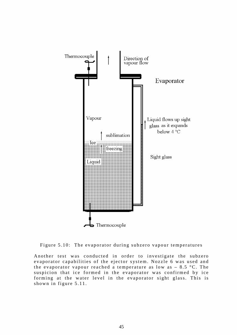
45
F igu re 5 .10 : The evaporato r du r i ng subzero vapour tempera tu res Another t es t was conduc ted in o rder to i nves t i ga te the subzero evaporato r capab i l i t i es o f the e jec to r s ys tem. Nozz le 6 was used and the evapora to r vapour reached a tempera tu re as low as – 8 .5 °C . The susp i c ion tha t i ce fo rmed in the evaporato r was conf i rmed b y i ce fo rm ing a t the wate r leve l in the evaporato r s i gh t g lass . Th is i s shown in f i gure 5 .11 .
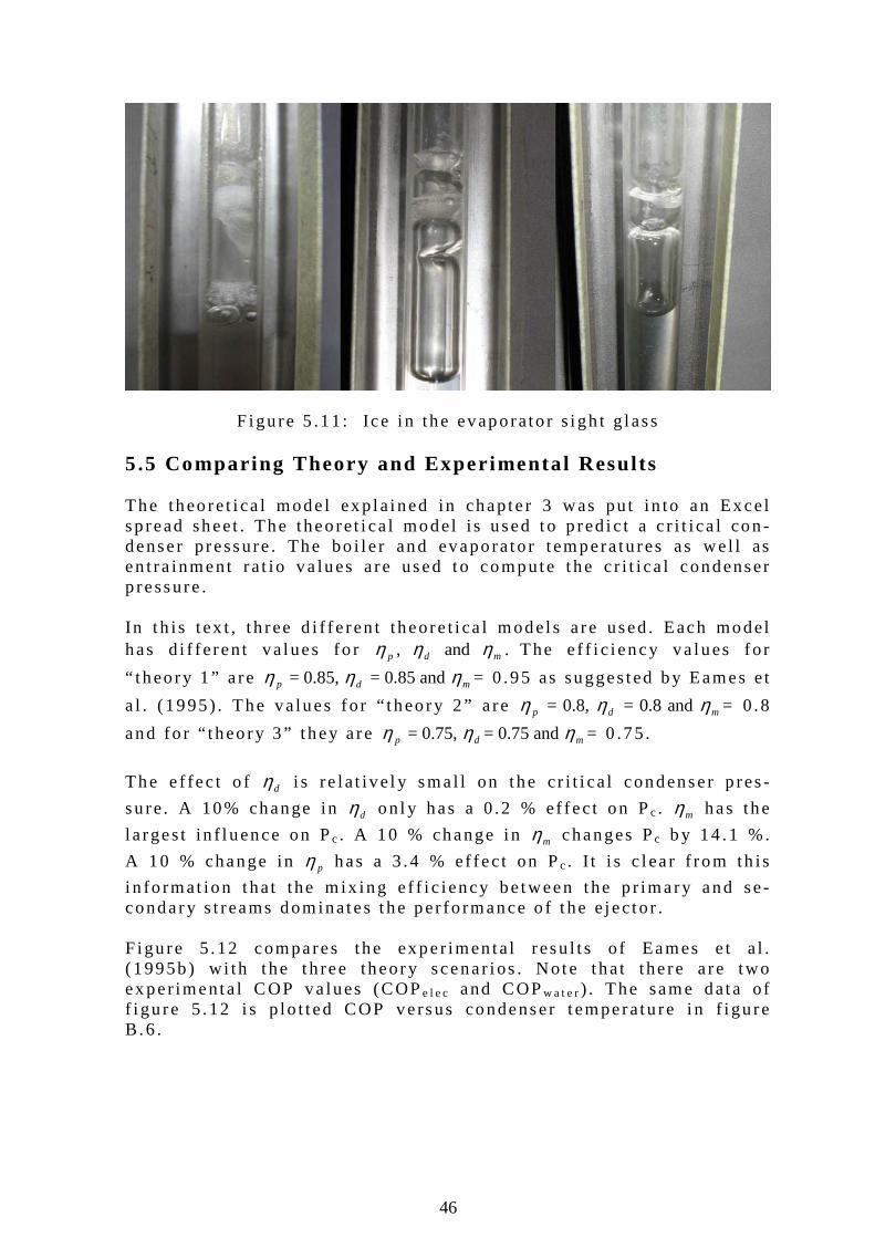
46
F igu re 5 .11 : Ice i n the evaporato r s i gh t g lass 5.5 Compar ing Theory and Exper imenta l Resul ts The theo re t i ca l mode l exp la ined in chapte r 3 was pu t in to an Exce l sp read sheet . The theo re t i ca l model i s used to p red i c t a c r i t i ca l con -denser p ressure . The bo i l e r and evaporato r t empera tu res as wel l as en t ra inment ra t io va lues a re used to compute the c r i t i ca l condenser p ressure . In t h is t ex t , t h ree d i f fe ren t theore t i ca l models a re used. Each model has d i f fe ren t va lues fo r pη , dη and mη . The e f f i c i ency va lues fo r
“ t heo ry 1 ” a re pη = 0.85, dη = 0.85 and mη = 0 .95 as sugges ted by Eames e t
a l . (1995) . The va lues fo r “ t heo ry 2 ” a re pη = 0.8, dη = 0.8 and mη = 0 .8
and fo r “ t heo ry 3 ” t hey a re pη = 0.75, dη = 0.75 and mη = 0 .75 .
The e f fec t o f dη i s re la t i ve l y sma l l on the cr i t i ca l condenser p res -
su re . A 10% change in dη on l y has a 0 .2 % ef fec t on Pc . mη has the
l a rges t in f l uence on Pc . A 10 % change i n mη changes Pc b y 14 .1 %.
A 10 % change in pη has a 3 .4 % ef fec t on Pc . I t i s c l ea r f rom th is
i n fo rmat ion that the m ix ing e f f i c i ency be tween the p r imary and se -condary s t reams dominates the per fo rmance o f t he e jec to r . F igu re 5 .12 compares the exper imen ta l resu l t s o f Eames e t a l . (1995b) w i th t he th ree theory scenar ios . Note that the re a re two ex per imenta l COP va lues (COPe l e c and COPw a t e r) . The same data of f i gu re 5 .12 i s p lo t t ed COP versus condenser t emperatu re i n f i gu re B .6 .
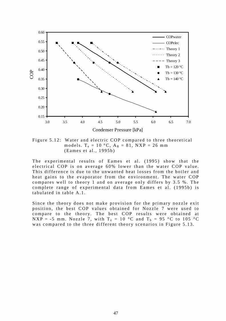
47
0.15
0.20
0.25
0.30
0.35
0.40
0.45
0.50
0.55
0.60
3.0 3.5 4.0 4.5 5.0 5.5 6.0 6.5 7.0
Condenser Pressure [kPa]
CO
P COPwater
COPelec
Theory 1
Theory 2
Theory 3
Tb = 120 °C
Tb = 130 °C
Tb = 140 °C
F igu re 5 .12 : Wate r and e lec t r i c COP compared to t h ree theo re t i ca l models . Te = 10 °C, AR = 81 , NXP = 26 mm
(Eames e t a l . , 1995b) The ex per imenta l resu l ts o f Eames e t a l . (1995) show that t he e lec t r i ca l COP i s on average 60% lower than the wate r COP va lue. Th i s d i f fe rence i s due to the unwanted heat l osses f rom the bo i l e r and hea t ga ins to the evaporato r f rom the env i ronment . The wa te r COP compares we l l to theo ry 1 and on average on l y d i f fe rs by 3 .5 %. The comple te range o f exper imenta l data f rom Eames e t a l . (1995b) i s t abu la ted in t ab le A .1 . S ince the theo ry d oes no t make p rov is ion fo r the p r imary nozz le ex i t pos i t i on , the bes t COP va lues ob ta ined fo r Nozz le 7 were used to compare to the theo ry. The bes t COP resu l t s were ob ta ined a t NXP = -5 mm. Nozz le 7 , w i th Te = 10 °C and Tb = 95 °C to 105 °C was compared to the th ree d i f fe ren t theo ry scenar ios in F igu re 5 .13 .
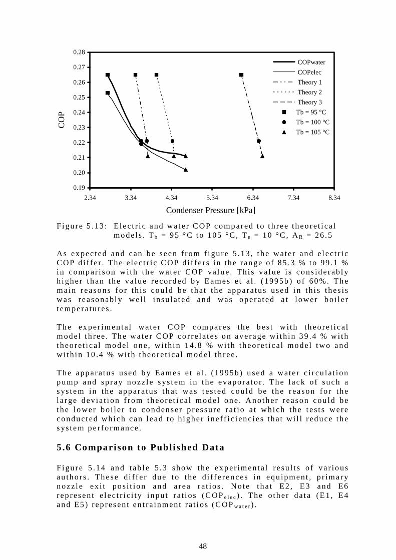
48
0.19
0.20
0.21
0.22
0.23
0.24
0.25
0.26
0.27
0.28
2.34 3.34 4.34 5.34 6.34 7.34 8.34
Condenser Pressure [kPa]
CO
P COPwater
COPelec
Theory 1
Theory 2
Theory 3
Tb = 95 °C
Tb = 100 °C
Tb = 105 °C
F igu re 5 .13 : E lec t r i c and wa ter COP compared to t h ree theo re t i ca l
models . Tb = 95 °C to 105 °C , Te = 10 °C , AR = 26 .5 As expec ted and can be seen f rom f i gu re 5 .13 , t he wate r and e lec t r i c COP d i f fe r . The e lec t r i c COP d i f fe rs i n the range o f 85 .3 % to 99 .1 % in compar ison w i th the wate r COP va lue. Th i s va lue i s cons iderab l y h igher t han the va lue reco rded by Eames e t a l . (1995b) o f 60%. The main reasons fo r th is cou ld be that the appara tus used i n th i s thes is was reasonab l y we l l i nsu la ted and was operated a t l ower bo i l e r t emperatu res . The exper imen ta l wa ter COP compares the bes t w i th theo re t i ca l model t h ree . The wa te r COP co r re la tes on average w i th in 39 .4 % w i th t heo re t i ca l model one, w i th in 14 .8 % w i th theo re t i ca l model two and w i th in 10 .4 % wi th theore t i ca l model t h ree . The apparatus used b y Eames e t a l . (1995b) used a wate r c i r cu la t i on pump and sp ray nozz le s ys tem in t he evaporato r . The l ack o f such a s ys tem in the appara tus that was tes ted cou ld be the reason fo r the l a rge dev ia t i on f rom theore t i ca l model one . Another reason cou ld be the l ower bo i l e r to condenser p ressu re ra t io a t wh ich the tes t s were conducted wh ich can l ead to h igher ine f f i c i enc ies that w i l l reduce the s ys tem per fo rmance . 5.6 Compar ison to Publ ished Data Figu re 5 .14 and tab le 5 .3 show the ex per imenta l resu l t s o f va r ious au thors . These d i f fe r due to t he d i f fe rences i n equ ipment , p r imary nozz le ex i t pos i t ion and a rea ra t ios . Note tha t E2 , E3 and E6 rep resent e lec t r i c i t y i npu t ra t i os (COPe l e c) . The o ther da ta (E1, E4 and E5) rep resent en t ra inment ra t i os (COPw a t e r) .
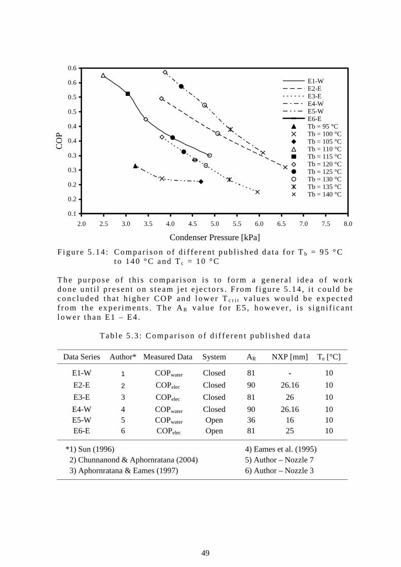
49
0.1
0.2
0.2
0.3
0.3
0.4
0.4
0.5
0.5
0.6
0.6
2.0 2.5 3.0 3.5 4.0 4.5 5.0 5.5 6.0 6.5 7.0 7.5 8.0
Condenser Pressure [kPa]
CO
P
E1-W E2-E E3-E E4-W E5-W E6-E Tb = 95 °C Tb = 100 °C Tb = 105 °C Tb = 110 °C Tb = 115 °C Tb = 120 °C Tb = 125 °C Tb = 130 °C Tb = 135 °C Tb = 140 °C
F igu re 5 .14 : Compar i son o f d i f fe ren t pub l i shed data fo r Tb = 95 °C t o 140 °C and Tc = 10 °C The pu rpose o f th i s compar i son i s to fo rm a genera l idea o f work done un t i l p resent on s team je t e jec to rs . F rom f i gu re 5 .14 , i t cou ld be conc luded tha t h igher COP and l ower Tc r i t va lues wou ld be ex pected f rom the exper imen ts . The AR va lue fo r E5 , however , i s s i gn i f i can t l ower t han E1 – E4.
Tab le 5 .3 : Compar ison o f d i f fe ren t pub l i shed da ta
Data Series Author* Measured Data System AR NXP [mm] Te [°C]
E1-W 1 COPwater Closed 81 - 10
E2-E 2 COPelec Closed 90 26.16 10
E3-E 3 COPelec Closed 81 26 10
E4-W 4 COPwater Closed 90 26.16 10 E5-W 5 COPwater Open 36 16 10 E6-E 6 COPelec Open 81 25 10
*1) Sun (1996) 4) Eames et al. (1995) 2) Chunnanond & Aphornratana (2004) 5) Author – Nozzle 7 3) Aphornratana & Eames (1997) 6) Author – Nozzle 3
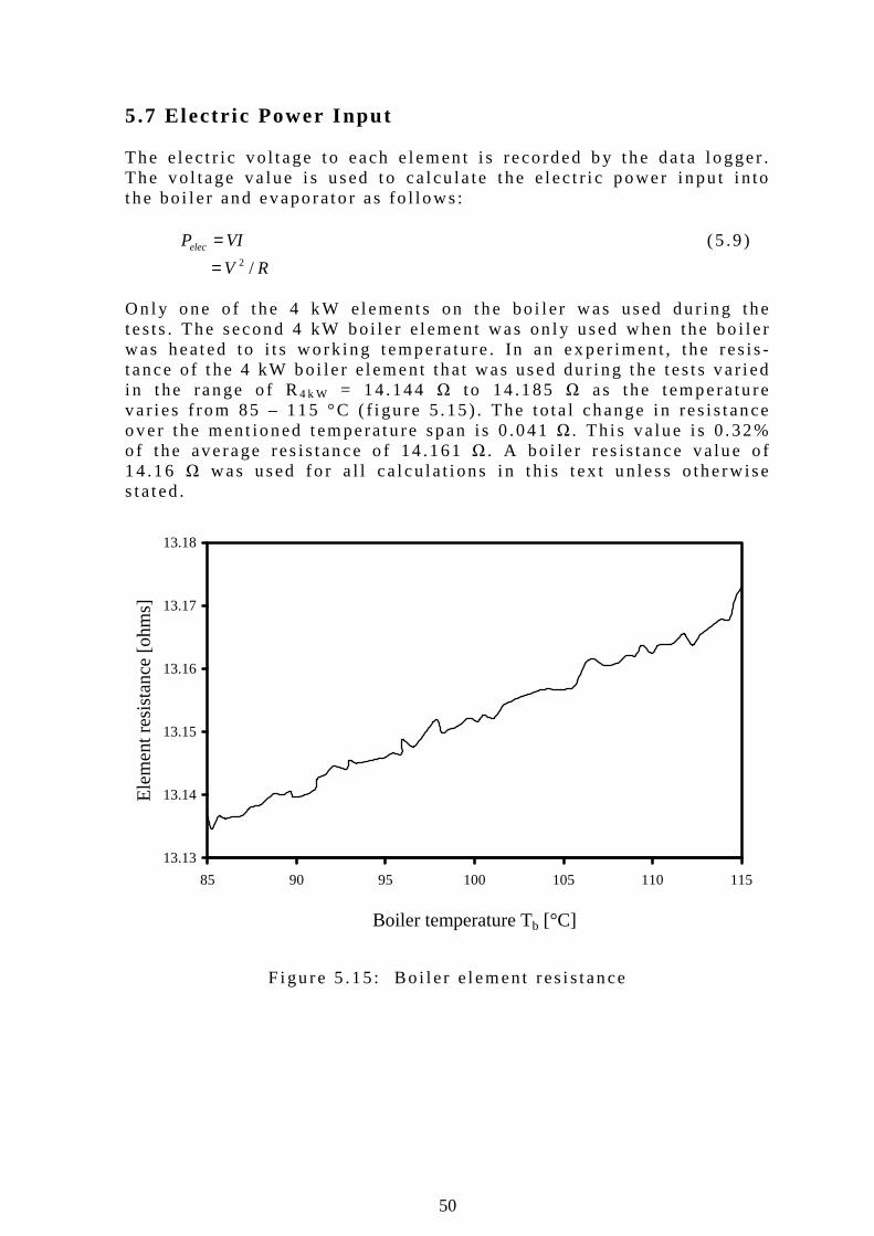
50
5.7 Electr ic Power Input The e lec t r i c vo l t age to each e lemen t i s reco rded b y the da ta l ogger . The vo l tage va lue i s used to ca l cu la te t he e lec t r i c power inpu t i n to t he bo i l e r and evaporato r as fo l lows:
VIPelec = (5 .9 )
RV /2= On l y one o f t he 4 kW e lements on the bo i l e r was used du r i ng the tes ts . The second 4 kW bo i l e r e lement was on l y used when the bo i l e r was heated to i t s wo rk ing tempera tu re . In an ex per imen t , the res is -t ance o f t he 4 kW bo i le r e lement tha t was used du r i ng the tes t s va r i ed i n t he range o f R4 k W = 14 .144 Ω to 14 .185 Ω as the tempera tu re va r i es f rom 85 – 115 °C ( f i gu re 5 .15 ) . The to ta l change i n res i s tance over the ment ioned tempera tu re span i s 0 .041 Ω . Th i s va lue i s 0 .32% o f the average res is tance o f 14 .161 Ω . A bo i le r res is tance va lue o f 14 .16 Ω was used fo r a l l ca l cu la t i ons i n t h i s t ex t un less o the rw ise s ta ted .
F igu re 5 .15 : Bo i l e r e lement res i s tance
13.13
13.14
13.15
13.16
13.17
13.18
85 90 95 100 105 110 115
Boiler temperature Tb [°C]
Ele
men
t res
ista
nce
[ohm
s]
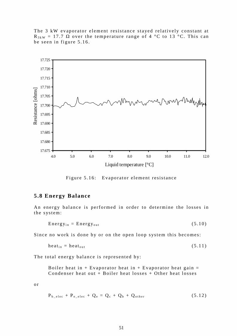
51
17.675
17.680
17.685
17.690
17.695
17.700
17.705
17.710
17.715
17.720
17.725
4.0 5.0 6.0 7.0 8.0 9.0 10.0 11.0 12.0
Liquid temperature [°C]
Res
ista
nce
[ohm
s]The 3 kW evapora to r e lement res is tance s tayed re la t i ve ly cons tan t at R3 k W = 17 .7 Ω over t he temperature range o f 4 °C to 13 °C. Th i s can be seen i n f i gu re 5 .16 .
F igu re 5 .16 : Evaporato r e lement res is tance
5.8 Energy Balance An energy ba lance i s per fo rmed in o rder to dete rmine the l osses i n t he sys tem:
Energyi n = Energyo u t (5 .10 ) S ince no work i s done by o r on the open l oop sys tem th is becomes:
hea ti n = heato u t (5 .11 ) The to ta l energy ba lance i s rep resented by:
Bo i l e r heat in + Evaporato r heat i n + Evaporato r heat ga in = Condenser heat ou t + Bo i l e r heat losses + Other hea t l osses
o r
Pb _ e l e c + Pe _ e l e c + Qe = Qc + Qb + Qo t h e r (5 .12 )
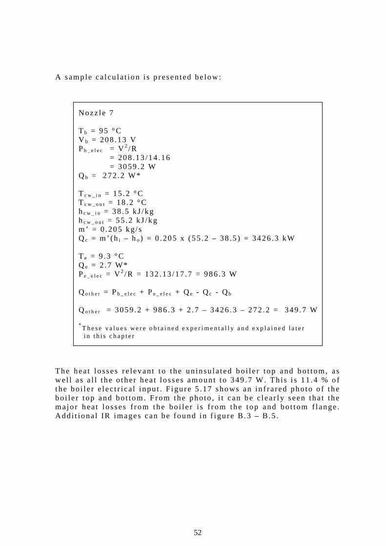
52
A samp le ca l cu la t ion i s p resented be low:
Nozz le 7
T b = 95 °C V b = 208.13 V Pb _ e l e c = V 2 /R
= 208.13 /14 .16 = 3059 .2 W
Qb = 272 .2 W* T c w _ i n = 15 .2 °C T c w _ o u t = 18 .2 °C hc w _ i n = 38 .5 kJ /kg hc w _ o u t = 55 .2 kJ /kg m ’ = 0 .205 kg/s Qc = m ’ (h i – ho) = 0 .205 x (55 .2 – 38 .5 ) = 3426 .3 kW
T e = 9 .3 °C Qe = 2 .7 W* Pe _ e l e c = V2 /R = 132 .13 /17 .7 = 986.3 W
Qo t h e r = Pb _ e l e c + Pe _ e l e c + Qe - Qc - Qb
Qo t h e r = 3059.2 + 986 .3 + 2 .7 – 3426.3 – 272 .2 = 349.7 W
* T h e s e v a l u e s we r e o b t a i n e d e x p e r i me n t a l l y a n d e x p l a i n e d l a t e r i n t h i s c h a p t e r
The hea t losses re levant t o t he un insu la ted bo i l e r t op and bo t tom, as we l l as a l l the o ther hea t losses amoun t to 349 .7 W. Th is i s 11 .4 % o f t he bo i l e r e lec t r i ca l inpu t . F igu re 5 .17 shows an in f rared photo o f t he bo i le r top and bo t tom. F rom the photo , i t can be c lea r l y seen tha t the majo r heat losses f rom the bo i l e r i s f rom the top and bo t tom f l ange . Add i t iona l IR images can be found i n f i gu re B .3 – B .5 .
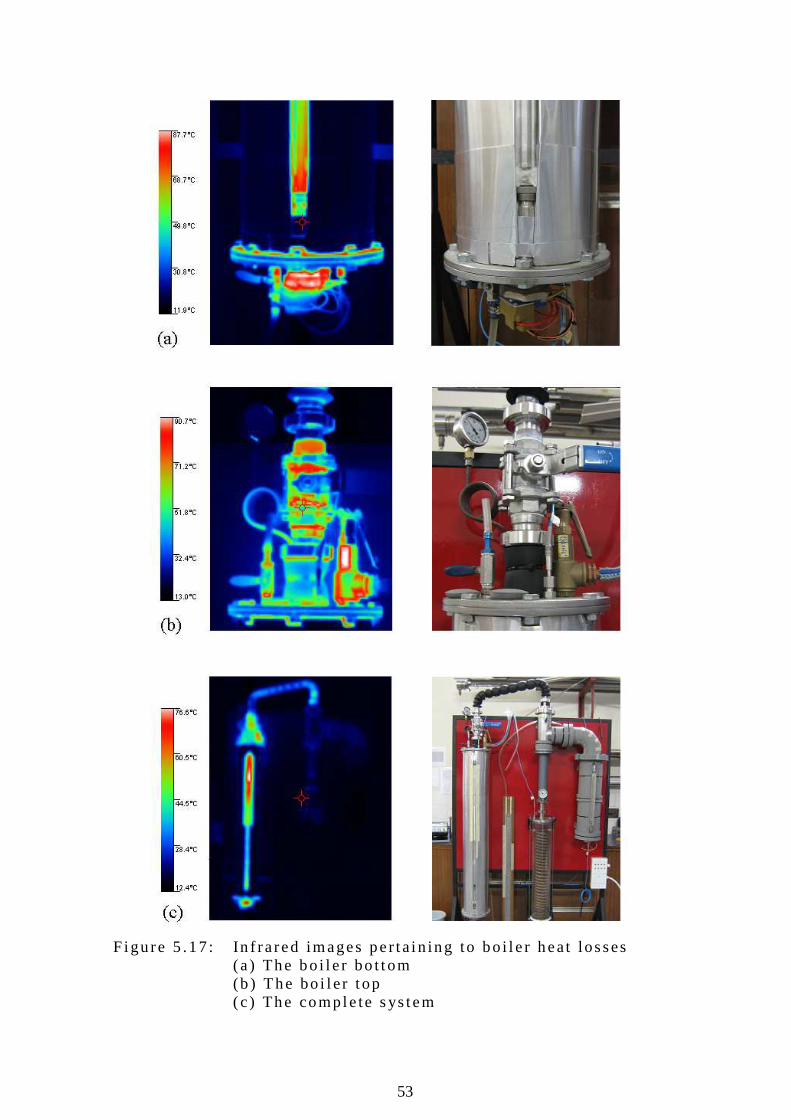
53
F igu re 5 .17 : In f ra red images per ta in ing to bo i l e r heat losses
(a ) The bo i l e r bo t tom (b ) The bo i l e r t op ( c ) The comple te s ys tem

54
65
70
75
80
85
90
95
100
105
110
115
0 5 10 15 20 25 30
Time [h]
Boi
ler
tem
pera
ture
[°C
]
200
220
240
260
280
300
320
340
Boi
ler
elem
ent v
olta
ge [V
]
Tb
Vb
5.9 Boi ler and Evaporator Heat Losses and Gains 5 .9 .1 Bo i l e r hea t losses Tes ts were conduc ted to de termine the bo i l e r hea t l osses . In a t yp i ca l t es t , the the rmosta t on the bo i l e r e lemen ts was set to 100 °C. The tes t was conducted over a t ime span o f 32 hours . Bo i l e r t emperatures were main ta ined near 100 °C and recorded every 15 s . The bo i l e r heat l osses a re equa l to t he bo i le r energy i nput . T yp i ca l t es t resu l t s can be seen i n f i gure 5 .18 . F igu re 5 .18 : Bo i l e r temperatures and vo l tages du r ing a bo i l e r
i nsu la t ion tes t a t Tb = 100 °C The to ta l bo i l e r hea t loss ve rsus amb ien t t empera tu re o f t he same tes t i s shown in f i gu re 5 .19 . The ambien t t emperatu re va r i ed i n the range T a = 12 .3 °C to 14 .0 °C . The bo i l e r hea t l osses s tayed re la t i ve l y cons tan t a t 260 W th roughout t he dura t i on o f the tes t . F rom f i gu re 5 .19 , i t can be observed tha t t he va r ia t i on o f t he ambien t t emperatu re i n t he reco rded tempera tu re range has a min imal e f fec t on the bo i l e r hea t l osses . S im i l a r t es ts a t d i f fe ren t bo i l e r tempera tu res and bo i le r l i qu id vo lumes were conduc ted . The resu l ts o f these tes ts can be i n te rpo la ted to p red i c t t he bo i l e r heat losses fo r a par t i cu la r bo i l e r opera t i ng tempera tu re and l iqu id vo lume.
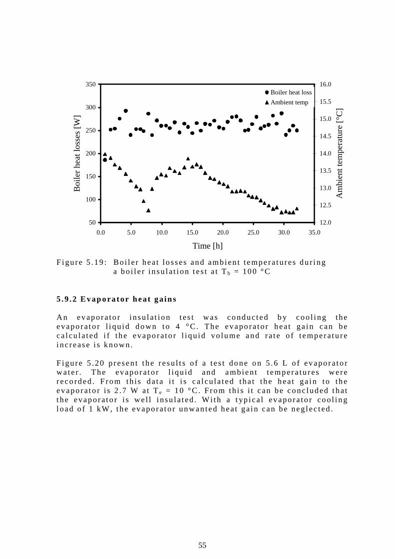
55
50
100
150
200
250
300
350
0.0 5.0 10.0 15.0 20.0 25.0 30.0 35.0
Time [h]
Boi
ler
heat
loss
es [W
]
12.0
12.5
13.0
13.5
14.0
14.5
15.0
15.5
16.0
Am
bien
t tem
pera
ture
[°C
]
Boiler heat loss
Ambient temp
F igu re 5 .19 : Bo i l e r heat losses and ambien t temperatures du r i ng
a bo i l e r insu la t i on tes t a t Tb = 100 °C 5 .9 .2 Evapora tor heat ga ins An evapora to r i nsu la t ion tes t was conducted b y coo l i ng the evaporato r l i qu id down to 4 °C. The evaporator heat ga in can be ca l cu la ted i f the evaporato r l i qu id vo lume and ra te o f t emperatu re i ncrease i s known. F igu re 5 .20 p resent t he resu l ts o f a tes t done on 5 .6 L o f evaporato r wa te r . The evaporato r l i qu id and ambien t t empera tu res were reco rded. F rom th is data i t i s ca l cu la ted tha t the heat ga in to the evaporato r i s 2 .7 W at Te = 10 °C . From th i s i t can be conc luded that t he evaporato r i s we l l i nsu la ted . Wi th a t yp i ca l evapora to r coo l i ng l oad o f 1 kW, the evaporato r unwan ted heat ga in can be neg lec ted .
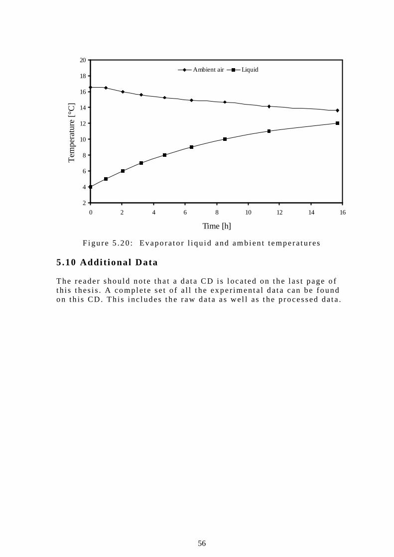
56
2
4
6
8
10
12
14
16
18
20
0 2 4 6 8 10 12 14 16
Time [h]
Tem
pera
ture
[°C
]Ambient air Liquid
F igu re 5 .20 : Evaporato r l i qu id and ambien t temperatures
5.10 Addi t ional Data The reader shou ld no te tha t a data CD is l oca ted on the las t page o f t h is t hes i s . A comple te set o f a l l t he exper imenta l data can be found on th is CD. Th is i nc ludes the raw da ta as wel l as the processed data .
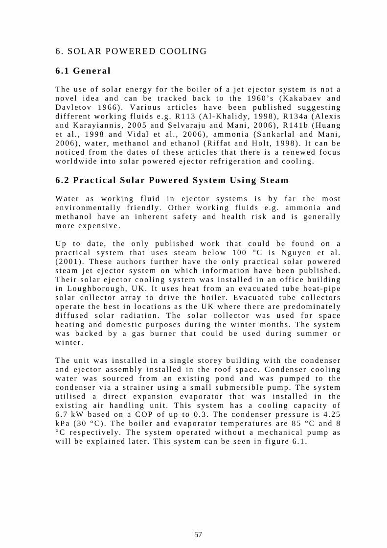
57
6. SOLAR POWERED COOLING 6.1 General The use o f so la r energy fo r t he bo i l e r o f a j e t e jec to r sys tem is no t a nove l idea and can be t racked back to the 1960 ’s (Kakabaev and Dav le tov 1966) . Var ious a r t i c l es have been pub l i shed sugges t i ng d i f fe ren t work ing f l u i ds e .g . R113 (A l -Kha l i d y, 1998) , R134a (A lex is and Karayiann is , 2005 and Se lva ra ju and Man i , 2006) , R141b (Huang e t a l . , 1998 and V ida l e t a l . , 2006) , ammon ia (Sankar la l and Man i , 2006) , wate r , methano l and e thano l (R i f fa t and Ho l t , 1998) . I t can be no t i ced f rom the da tes o f these a r t i c les that t here i s a renewed focus wor ldwide i n to so la r powered e jec to r re f r i ge ra t i on and coo l ing . 6.2 Pract ica l Solar Powered System Using Steam Wate r as work ing f l u i d i n e jec to r s ys tems i s b y f a r t he most env i ronmenta l l y f r i end l y. O ther work ing f l u i ds e .g . ammonia and methano l have an i nheren t sa fe t y and hea l th r i sk and i s genera l l y more expens ive . Up to date , t he on l y pub l i shed work that cou ld be found on a p rac t i ca l s ys tem tha t uses s team be low 100 °C i s Ngu yen e t a l . (2001) . These au tho rs fu r ther have the on l y p rac t i ca l so la r powered s team je t e jec to r sys tem on wh ich i n fo rmat ion have been pub l i shed. The i r so la r e jec to r coo l i ng sys tem was i ns ta l l ed i n an o f f i ce bu i l d i ng i n Loughborough , UK. I t uses heat f rom an evacuated tube hea t -p ipe so la r co l l ec to r a r ray to d r i ve the bo i le r . Evacua ted tube co l l ec to rs opera te the bes t i n l ocat i ons as the UK where the re a re p redominate l y d i f fused so la r rad ia t ion . The so lar co l l ec to r was used fo r space hea t ing and domest i c pu rposes du r i ng the w in te r months . The sys tem was backed b y a gas bu rner tha t cou ld be used dur ing summer o r w in ter . The un i t was ins ta l l ed i n a s ing le s to rey bu i l d i ng w i th the condenser and e jec to r assembl y i ns ta l l ed i n t he roo f space . Condenser coo l i ng wa te r was sou rced f rom an ex is t ing pond and was pumped to t he condenser v ia a s t ra iner us ing a smal l submers ib le pump. The s ys tem u t i l i sed a d i rec t ex pans ion evaporato r t ha t was i ns ta l l ed i n t he ex is t ing a i r hand l ing un i t . Th is sys tem has a coo l ing capac i t y o f 6 .7 kW based on a COP o f up to 0 .3 . The condenser p ressu re i s 4 .25 kPa (30 °C) . The bo i l e r and evaporator t emperatu res a re 85 °C and 8 °C respec t i ve l y. T he s ys tem opera ted w i thout a mechan ica l pump as w i l l be exp la ined la te r . Th i s sys tem can be seen i n f i gu re 6 .1 .
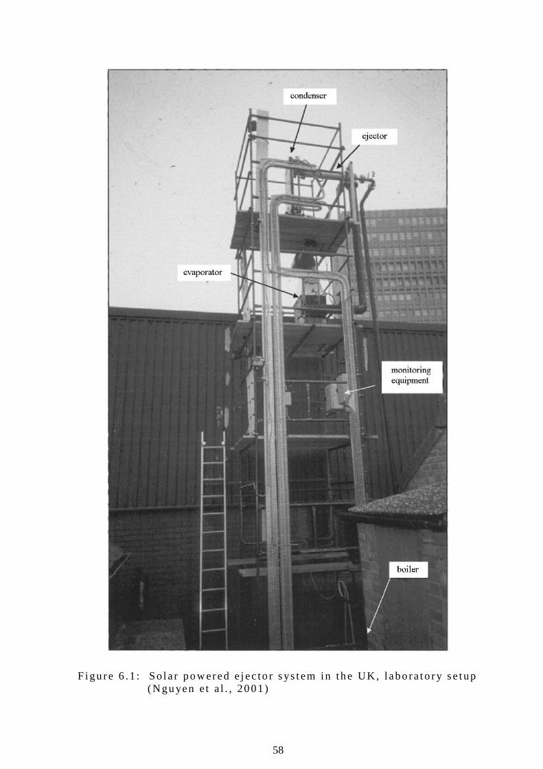
58
F igu re 6 .1 : So la r powered e jec to r sys tem in the UK, labo ra to ry se tup (Ngu yen e t a l . , 2001)
59
Ngu yen e t a l . (2001) fa i l ed to spec i fy an y c r i t i ca l des ign da ta e .g . p r imary nozz le th roat s ize , e jec to r p ro f i l e and secondary nozz le t h roat s ize , e t c . Some exper imen ta l data was ob ta ined f rom the au thors th rough persona l communica t i on . An examp le o f t he i r ex per imenta l resu l ts can be seen in f igu re 6 .2 . I t can be no ted f rom the f i gu re (add i t iona l s ymbols were added fo r t he ease o f t he reader ) t ha t the s ys tem opera tes a t a bo i l e r t empera tu re near Tb = 80 °C. The condenser p ressu re va r i ed between Pc = 2 .66 kPa to 3 .21 kPa (Tc = 23 .1 °C to 25 .2 °C) . The usab le evaporato r coo led wa ter ou tpu t was i n the range Te w _ o u t = 4 °C to 5 °C .
F igu re 6 .2 : Exper imenta l data f rom a s team je t e jec to r coo l ing sys tem ins ta l l ed in the UK (Tony, 2005) 6.3 Pract ica l Impl icat ions 6 .3 .1 N igh t t ime coo l ing The ques t ion o f how to coo l o r re f r i ge ra te dur ing the n igh t us ing so la r energy i s qu i te popu la r . The use o f phase change mate r i a l s (PCM) i s a s imp le and pass ive method o f ach iev ing n igh t - t ime coo l i ng . A PCM i s a chemica l m ix tu re that changes phase between l iqu id and so l id a t a p redete rmined temperatu re . Ice i s the best ex ample o f a na tu ra l PCM. I f so lar the rmal coo l i ng i s used to re f r i ge ra te , the i nner wa l l s o f a f r idge cou ld be l ined w i th a PCM of a p re fe r red tempera tu re . PCM
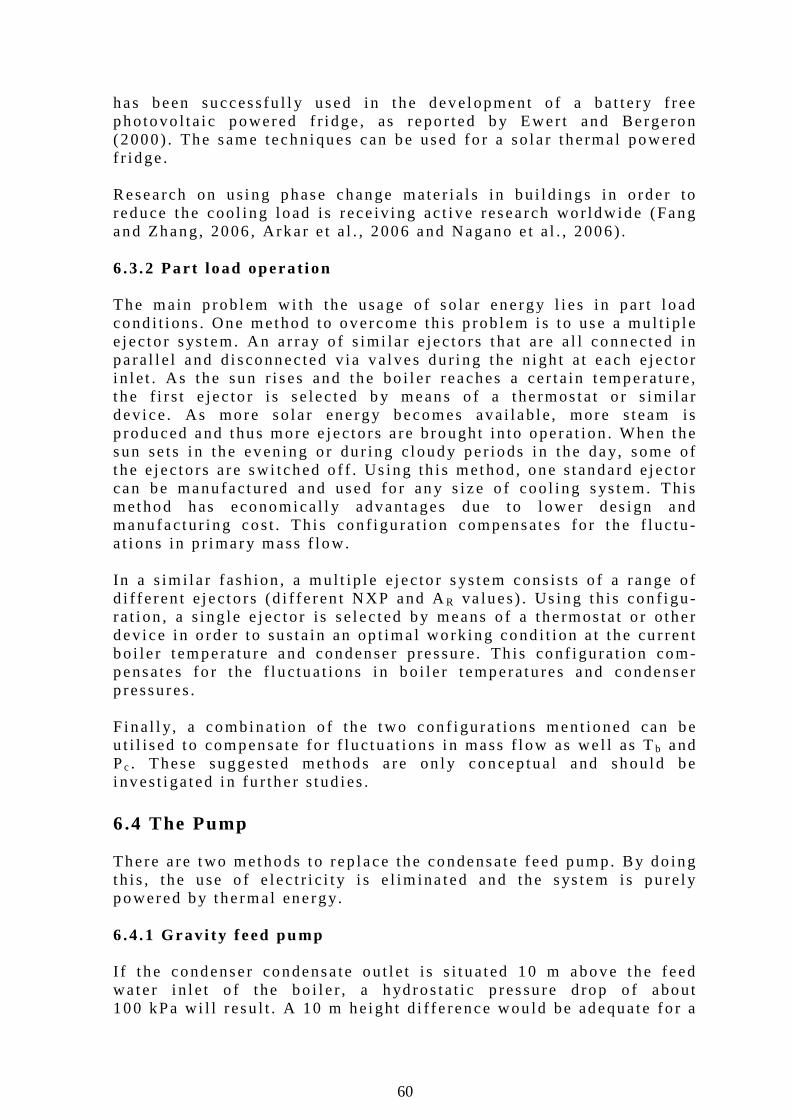
60
has been success fu l l y used in t he deve lopment o f a bat ter y f ree photovo l ta i c powered f r idge , as repo r ted b y Ewer t and Bergeron (2000) . The same techn iques can be used fo r a so la r t hermal powered f r idge . Research on us ing phase change mate r i a l s in bu i l d i ngs in o rder to reduce the coo l ing l oad i s rece iv ing ac t i ve research wor ldw ide (Fang and Zhang, 2006 , Arkar e t a l . , 2006 and Nagano e t a l . , 2006) . 6 .3 .2 Par t load opera t i on The main p rob lem w i th the usage o f so la r energy l i es i n par t l oad cond i t i ons . One method to overcome th is p rob lem i s to use a mul t i p l e e jec to r sys tem. An a r ray o f s im i la r e jec to rs t ha t are a l l connected i n pa ra l l e l and d i sconnec ted v ia va l ves du r i ng the n igh t a t each e jec to r i n l e t . As the sun r i ses and the bo i l e r reaches a cer ta in t emperatu re , t he f i r s t e jec to r i s se lec ted b y means o f a t he rmos ta t o r s im i l a r dev i ce . As more so la r energy becomes ava i l ab le , more s team is p roduced and thus more e jec to rs a re b rought in to opera t ion . When the sun se ts i n the even ing o r du r ing c loud y per iods i n the day, some o f t he e jec to rs are swi tched o f f . Us ing th is method, one s tandard e jec to r can be manu fac tured and used fo r an y s i ze o f coo l ing s ys tem. Th is method has economica l l y advantages due to l ower des ign and manu fac tur ing cos t . Th i s con f i gu ra t ion compensates fo r t he f l uc tu -a t i ons in p r imary mass f low. In a s im i l a r fash ion , a mu l t ip l e e jec to r s ys tem cons is t s o f a range o f d i f fe ren t e jec to rs (d i f fe ren t NXP and AR va lues) . Us ing th is con f i gu -ra t i on , a s ing le e jec to r i s se lec ted by means o f a t he rmos ta t o r o ther dev i ce i n o rder to sus ta in an op t ima l work ing cond i t i on a t the cu r ren t bo i le r t emperatu re and condenser p ressu re . Th is conf igu ra t i on com-pensates fo r the f l uc tua t ions i n bo i le r t emperatu res and condenser p ressures . F ina l l y, a combinat ion o f the two con f i gura t ions ment ioned can be u t i l i sed to compensa te fo r f luc tuat i ons i n mass f l ow as we l l as Tb and Pc . These sugges ted methods a re on l y concep tua l and shou ld be i nves t i ga ted i n fu r the r s tud ies . 6.4 The Pump There a re two methods to rep lace the condensa te feed pump. By do ing th is , the use o f e lec t r i c i t y i s e l im ina ted and the sys tem is pu re l y powered by the rmal energy. 6 .4 .1 Grav i t y f eed pump I f t he condenser condensa te ou t l e t i s s i t ua ted 10 m above the feed wa te r i n l e t o f the bo i l e r , a h yd ros ta t i c p ressu re d rop o f about 100 kPa wi l l resu l t . A 10 m he igh t d i f fe rence wou ld be adequa te fo r a
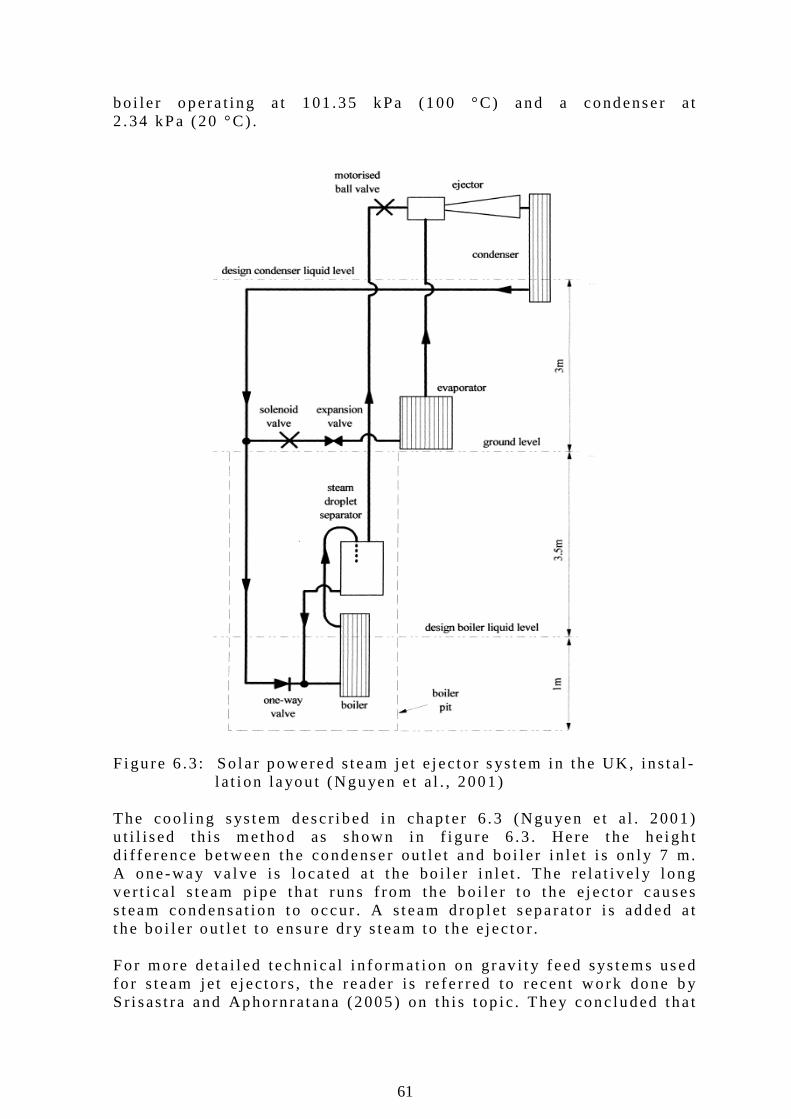
61
bo i le r opera t ing a t 101 .35 kPa (100 °C) and a condenser a t 2 .34 kPa (20 °C) . F igu re 6 .3 : So la r powered s team je t e jec to r s ys tem in the UK, ins ta l - l a t i on layou t (Nguyen e t a l . , 2001) The coo l i ng sys tem descr i bed i n chap ter 6 .3 (Ngu yen e t a l . 2001) u t i l i sed th is method as shown in f i gu re 6 .3 . Here the he igh t d i f fe rence between the condenser ou t le t and bo i l e r i n l e t i s on l y 7 m. A one-way va l ve i s l oca ted a t t he bo i l e r i n l e t . The re la t i ve l y l ong ve r t i ca l s team p ipe that runs f rom the bo i l e r t o t he e jec to r causes s team condensat ion to occur . A s team d rop le t separator i s added a t t he bo i l e r ou t le t to ensu re dr y s team to the e jec to r . Fo r more deta i l ed techn i ca l i n fo rmat ion on grav i t y feed sys tems used fo r s team je t e jec to rs , t he reader i s re fe r red to recent work done b y S r i sas t ra and Aphorn ra tana (2005) on th is t op i c . They conc luded tha t
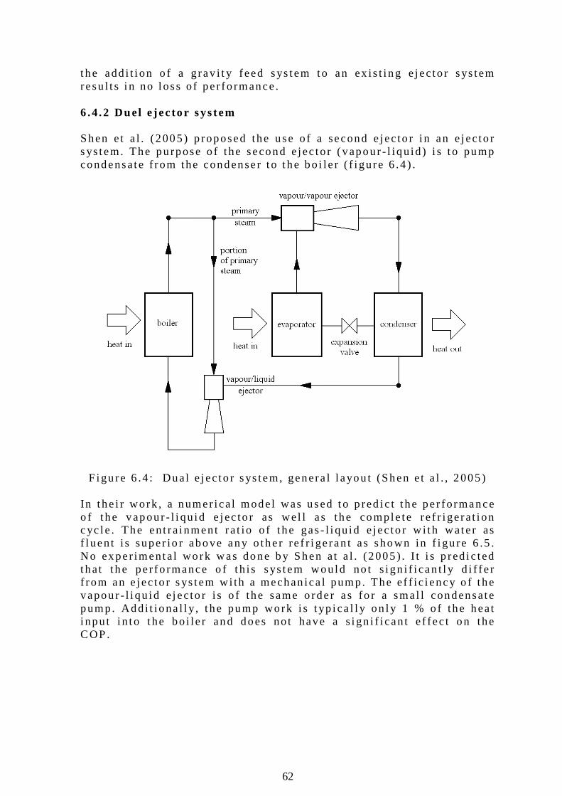
62
the add i t i on o f a g rav i t y feed sys tem to an ex is t i ng e jec to r sys tem resu l t s i n no l oss o f pe r fo rmance . 6 .4 .2 Duel e jec to r sys tem Shen e t a l . (2005) p roposed the use o f a second e jec to r i n an e jec to r s ys tem. The pu rpose o f t he second e jec to r ( vapour - l iqu id ) i s t o pump condensate f rom the condenser t o t he bo i le r ( f i gure 6 .4 ) .
F igu re 6 .4 : Dua l e jec to r sys tem, genera l l ayou t (Shen e t a l . , 2005) In t he i r work , a numer i ca l model was used to p red i c t t he per fo rmance o f t he vapour - l i qu id e jec to r as wel l as the comple te re f r i ge ra t i on cyc le . The en t ra inment ra t io o f t he gas - l i qu id e jec to r w i th wate r as f l uen t i s super io r above any o ther re f r i ge ran t as shown in f i gu re 6 .5 . No exper imenta l work was done by Shen a t a l . (2005) . I t i s p red i c ted that t he per fo rmance o f t h is sys tem wou ld no t s i gn i f i can t l y d i f fe r f rom an e jec to r s ys tem w i th a mechan ica l pump. The e f f i c i ency o f t he vapour - l i qu id e jec to r i s o f the same o rder as fo r a smal l condensate pump. Add i t iona l l y , t he pump work i s t yp i ca l l y on l y 1 % o f the heat i npu t i n to t he bo i le r and does no t have a s ign i f i can t e f fec t on the COP.
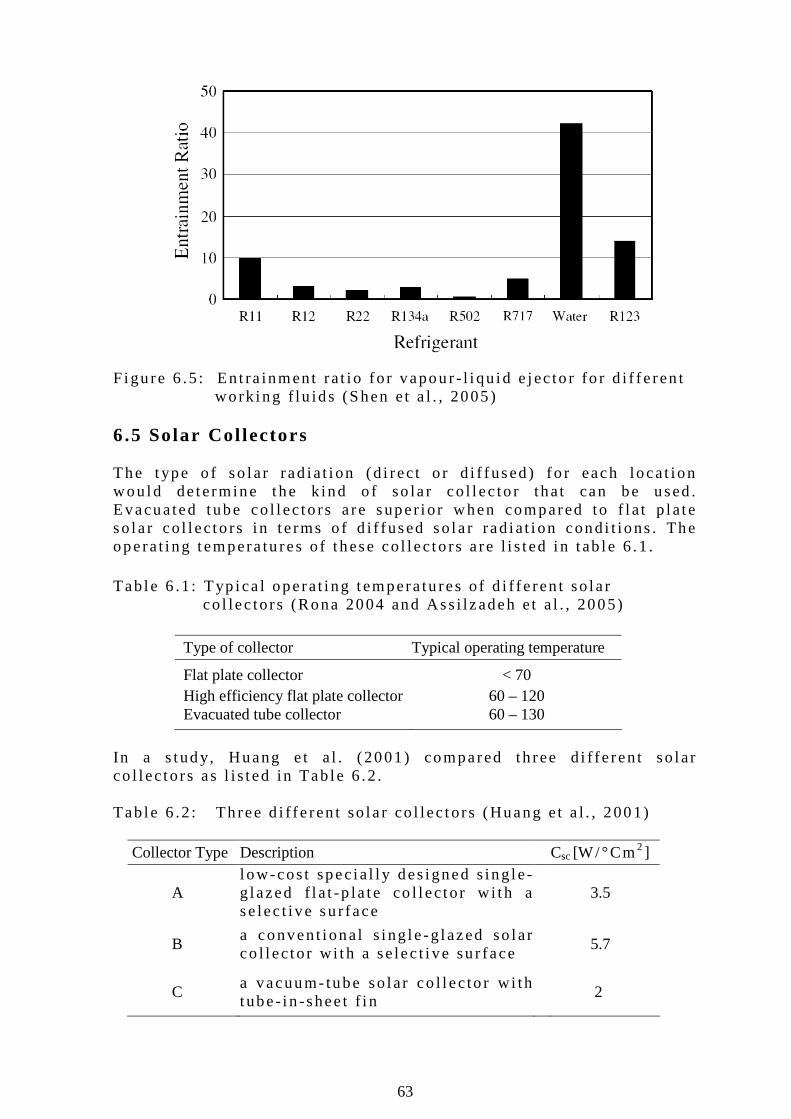
63
F igu re 6 .5 : En t ra inment ra t i o fo r vapour - l i qu id e jec to r fo r d i f fe ren t
wo rk ing f lu ids (Shen e t a l . , 2005) 6.5 Solar Col lectors The t ype o f so lar rad ia t i on (d i rec t o r d i f fused ) fo r each locat ion wou ld de termine the k ind o f so la r co l l ec to r tha t can be used . Evacua ted tube co l l ec to rs a re super io r when compared to f l a t p la te so la r co l l ec to rs i n t e rms o f d i f fused so la r rad ia t i on cond i t ions . The operat i ng tempera tu res o f t hese co l l ec to rs a re l i s ted i n t ab le 6 .1 . Tab le 6 .1 : Typ i ca l opera t i ng tempera tu res o f d i f fe ren t so la r co l lec to rs (Rona 2004 and Ass i l zadeh e t a l . , 2005) Type of collector Typical operating temperature
Flat plate collector < 70 High efficiency flat plate collector 60 – 120
Evacuated tube collector 60 – 130
In a s tud y, Huang e t a l . (2001) compared th ree d i f fe ren t so lar co l l ec to rs as l i s ted in Tab le 6 .2 . Tab le 6 .2 : Th ree d i f fe ren t so la r co l lec to rs (Huang e t a l . , 2001)
Collector Type Description Csc [W/ °Cm2 ]
A l ow-cos t spec ia l l y des igned s ing le -g lazed f l a t -p la te co l l ec to r w i th a se lec t i ve su r face
3.5
B
a convent i ona l s i ng le -g lazed so lar co l l ec to r w i th a se lec t i ve su r face
5.7
C
a vacuum-tube so lar co l l ec to r w i th t ube- in -shee t f i n
2
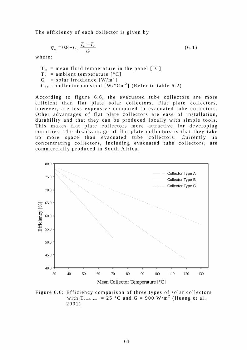
64
40.0
45.0
50.0
55.0
60.0
65.0
70.0
75.0
80.0
30 40 50 60 70 80 90 100 110 120 130
Mean Collector Temperature [°C]
Eff
icie
ncy
[%]
Collector Type A
Collector Type B
Collector Type C
The e f f i c i ency o f each co l l ec to r i s g iven b y
G
TTC am
scsc
−−= 8.0η (6 .1 )
where : Tm = mean f lu i d t empera tu re in t he pane l [ °C ] Ta = amb ien t t empera tu re [ °C ] G = so la r i r rad iance [W/m2 ] Cs c = co l l ec to r cons tan t [W/°Cm2 ] (Re fe r t o t ab le 6 .2 ) Acco rd ing to f i gure 6 .6 , the evacua ted tube co l l ec to rs a re more e f f i c i en t t han f l a t p la te so la r co l l ec to rs . F la t p l a te co l l ec to rs , however , a re less ex pens i ve compared to evacua ted tube co l lec to rs . O ther advantages o f f l a t p l a te co l l ec to rs a re ease o f i ns ta l l a t i on , du rab i l i t y and tha t t hey can be p roduced l oca l l y w i t h s imp le t oo l s . Th i s makes f l a t p l a te co l lec to rs more a t t rac t i ve fo r deve lop ing coun t r i es . The d isadvan tage o f f l a t p la te co l l ec to rs i s t ha t t hey take up more space than evacua ted tube co l l ec to rs . Cu r ren t l y no concent ra t ing co l lec to rs , inc lud ing evacuated tube co l lec to rs , a re commerc ia l l y p roduced in South A f r i ca . F igu re 6 .6 : E f f i c i ency compar ison o f t h ree t ypes o f so la r co l l ec to rs
w i t h Ta m b i e n t = 25 °C and G = 900 W/m2 (Huang e t a l . , 2001 )
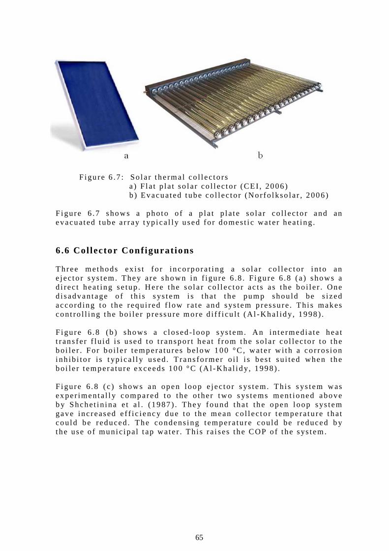
65
Figu re 6 .7 : So la r the rma l co l l ec to rs a ) F la t p la t so lar co l l ec to r (CEI , 2006) b ) Evacuated tube co l l ec to r (Nor fo l kso lar , 2006) F igu re 6 .7 shows a photo o f a p la t p la te so lar co l l ec to r and an evacuated tube a r ray t yp i ca l l y used fo r domest i c wa ter hea t i ng . 6.6 Col lector Conf igurat ions Th ree methods ex i s t fo r inco rpora t i ng a so la r co l l ec to r i n to an e jec to r sys tem. They a re shown in f igu re 6 .8 . F igu re 6 .8 (a ) shows a d i rec t heat ing se tup . Here the so la r co l l ec to r ac ts as the bo i l e r . One d isadvantage o f th is s ys tem i s that t he pump shou ld be s ized acco rd ing to the requ i red f l ow ra te and sys tem p ressu re . Th i s makes cont ro l l i ng the bo i le r p ressu re more d i f f i cu l t (A l -Kha l id y, 1998) . F igu re 6 .8 (b ) shows a c losed- loop s ys tem. An i n te rmed ia te hea t t rans fer f lu i d i s used to t ranspor t heat f rom the so la r co l lec to r t o t he bo i le r . For bo i l e r tempera tu res be low 100 °C , wate r w i th a co r ros ion i nh ib i to r i s t yp i ca l l y used. T rans fo rmer o i l i s bes t su i ted when the bo i le r t empera tu re ex ceeds 100 °C (A l -Kha l i d y, 1998) . F igu re 6 .8 (c ) shows an open l oop e jec to r s ys tem. Th is s ys tem was ex per imenta l l y compared to the o ther two s ys tems ment ioned above b y Shchet i n ina e t a l . (1987) . They found tha t the open l oop sys tem gave inc reased e f f i c i ency due to the mean co l l ec to r t emperatu re that cou ld be reduced. The condens ing tempera tu re cou ld be reduced b y the use o f mun ic ipa l t ap wate r . Th is ra i ses the COP o f t he sys tem.

66
F igu re 6 .8 : So la r powered e jec to r con f i gura t ions
(Sun and Eames , 1995) (a ) d i rec t hea t i ng (b ) c losed- loop ( c ) open- loop
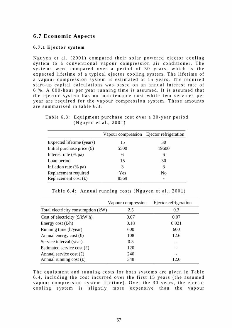
67
6.7 Economic Aspects 6 .7 .1 E jec to r sys tem Ngu yen e t a l . (2001) compared the i r so la r powered e jec to r coo l ing s ys tem to a conven t i ona l vapour compress ion a i r cond i t i oner . The s ys tems were compared over a per iod o f 30 years , wh ich i s the ex pected l i f e t ime o f a t yp i ca l e jec to r coo l i ng sys tem. The l i f e t ime o f a vapour compress ion sys tem i s es t imated a t 15 years . The requ i red s tar t -up cap i ta l ca lcu la t i ons was based on an annual in te res t ra te o f 6 %. A 600-hour pe r year runn ing t ime i s assumed. I t i s assumed that t he e jec to r sys tem has no main tenance cos t wh i l e two se rv i ces per year a re requ i red fo r t he vapour compress ion s ys tem. These amounts a re summar ised i n tab le 6 .3 . Tab le 6 .3 : Equ ipment pu rchase cos t over a 30 -year pe r i od
(Ngu yen e t a l . , 2001)
Vapour compressionEjector refrigeration
Expected lifetime (years) 15 30 Initial purchase price (£) 5500 19600 Interest rate (% pa) 6 6 Loan period 15 30 Inflation rate (% pa) 3 3 Replacement required Yes No
Replacement cost (£) 8569 -
Tab le 6 .4 : Annual runn ing cos ts (Nguyen e t a l . , 2001)
Vapour compression Ejector refrigeration
Total electricity consumption (kW) 2.5 0.3
Cost of electricity (£/kW h) 0.07 0.07 Energy cost (£/h) 0.18 0.021 Running time (h/year) 600 600 Annual energy cost (£) 108 12.6 Service interval (year) 0.5 - Estimated service cost (£) 120 - Annual service cost (£) 240 -
Annual running cost (£) 348 12.6
The equ ipment and runn ing cos ts fo r bo th sys tems a re g iven in Tab le 6 .4 , inc lud ing the cos t incur red over t he f i rs t 15 years ( t he assumed vapour compress ion s ys tem l i fe t ime) . Over t he 30 years , t he e jec to r coo l i ng sys tem is s l i gh t l y more ex pens ive than the vapour

68
compress ion s ys tem. The payback per i od fo r an e jec to r coo l ing s ys tem is app rox imate l y 33 years . A s im i la r economic ana l ys i s was per fo rmed as par t o f a p roposed so la r powered e jec to r a i r - cond i t i oner fo r a hosp i ta l in Mex i co . The s ys tem wou ld have a bo i l e r tempera ture o f 160 °C , a condenser t emperatu re o f 30 °C and an evaporato r t empera tu re o f 10 °C. The s ys tem wou ld have a 13 kW coo l ing capac i t y and a p red ic ted COP o f 0 .62 . The economic ana l ys i s p red i c ted a payback per i od o f 5 years (Wolper t e t a l . , 2000 and Wo lper t e t a l . , 2003) . In conc lus ion , the two case s tud ies rep resented p roo fed that a so lar d r i ven s team je t e jec to r a i r cond i t i on ing s ys tem is economic feas ib le . In genera l , the v iab i l i t y o f a so la r powered e jec to r a i r cond i t i oner does depend on the loca t ion where the sys tem i s ins ta l l ed , wh ich i n t u rn dete rmines the ava i l ab le sun l i gh t , e lec t r i c i t y cos t and equ ipment p r i ces . 6 .7 .2 So la r co l l ec to rs The so la r e jec to r s ys tem o f Nguyen e t a l . (2001) i n t he UK used evacuated tube co l l ec to rs to d r i ve the bo i l e r . A s tudy ex ecuted b y Meyer (2005) i nves t i ga ted the use o f f l a t p la te so la r co l l ec to rs . I t was conc luded tha t f l a t p la te so lar co l l ec to rs cou ld be used to d r i ve a s team je t e jec to r coo l i ng dev i ce i n l ocat i ons l i ke Southern A f r i ca where the re i s an abundance o f d i rec t so la r rad ia t i on . These s ys tems cou ld even opera te e f fec t i ve l y i n the w in te r months , espec ia l l y i n a reas tha t do no t rece ive w in te r ra in . I t was fu r the r conc luded that t he cos t o f f l a t p la te so la r co l l ec to rs i s about 30 % o f t he cos t o f evacuated tube co l l ec to rs . The compar ison was based on co l l ec to rs t hat p roduce s team a t the same tempera tu re and mass f low ra te . S ince the so la r co l l ec to r a r ray i s a s ign i f i can t cos t componen t o f a so la r d r i ven e jec to r s ys tem, th i s cou ld d ramat i ca l l y con t r ibu te to t he reduct i on o f the to ta l s ys tem cos t . 6 .7 .3 Vacuum coo l ing Another a rea where an e jec to r s ys tem has economica l advan tage i s i n t he co ld food s to rage i ndus t r y. The vacuum coo l i ng method becomes impract i ca l w i th convent i ona l s ys tems s ince the l a rge spec i f i c vo lume o f the evaporated gas a t l ow p ressu res requ i res compresso rs w i th h igh p ressure ra t i os and l a rge d isp lacemen t vo lumes. Sun and Eames (1995) conc luded tha t the s team je t re f r i ge ra t i on sys tems compete s t rong l y w i th mechan ica l compresso r sys tems in t hese app l i ca t ions . The p rac t i ca l ab i l i t y o f an e jec to r s ys tem to p roduce rap id coo l ing was d iscussed in chap ter 5 .3 .

69
7. SUMMARY, CONCLUSIONS AND RECOMMEN- DATIONS A work ing pro to t ype o f a s team je t e jec to r was manufac tu red and success fu l l y opera ted a t bo i l e r t empera tures be low 100 °C . F rom the work p resented i n t he prev ious chapte rs , i t can be fu r the r conc luded that the s team je t e jec to r i s a v iab le sys tem on a prac t i ca l and economica l bas is . 7.1 Summary A summary o f the ob jec t i ves and the i r ou tcomes a re :
7 .1 .1 Des ign and bu i l d a smal l sca le s team je t e jec to r exper imenta l se tup.
In chap te r 2 a smal l sca le s team je t e jec to r exper imenta l se tup was des igned and bu i ld . The setup i s o f an open l oop con f i gu ra - t ion and i t can opera te a t bo i l e r t emperatures in t he range o f Tb = 85 °C to 140 °C. Typ i ca l evaporato r l i qu id t empera tu res range f rom T e = 5 °C to 10 °C wh i l e t he wa ter -coo led condenser t empe-ra tu res range f rom Tc = 15 °C to 35 °C . The bo i l e r i s powered by two 4 kW e lec t r i c e lement . The coo l ing l oad i s s imu la ted b y a 3 kW e lec t r i c e lement . The e lec t r i c e lements a re cont ro l l ed b y the use o f a va r i ac . Pr imary nozz les w i th th roa t d iamete rs o f 1 .5 mm, 1 .75 mm, 2 .0 mm, 2 .5 mm, 3 .0 mm and 3 .5 mm were manu-fac tu red . The pos i t i on o f the p r imary nozz le can be va r i ed re la -t i ve to t he be l l mouth i n le t o f t he secondary nozz le . Th is i s accompl ished by us ing spacers o f d i f fe ren t l eng ths . On ly one secondary nozz le was cons t ruc ted w i th a th roa t d iamete r o f 18 mm. The s ta r t -up and operat iona l p rocedure o f the s ys tem is ex p la ined i n chapter 2 . 7 .1 .2 Exp la in the f l u i d dynamic theo ry re levan t t o the s team je t e jec to r. The theo ry based on pub l i shed work b y Eames e t a l . (1995a) i s ex p la ined i n chap te r 3 . The theo ry accoun ted fo r t he e f f i c i enc ies o f t he p r imary nozz le , m ix ing chamber and d i f fuser . Out o f t hese th ree e f f i c i enc ies , t he d i f fuser e f f i c i ency has the smal l es t con t r i bu t ion to the s ys tem per fo rmance . The e f f i c i ency o f t he m ix ing chamber i s more dominant t han the o ther two e f f i c i enc ies . The theo ry l acks in de f in ing the e f fec t o f va r i a t i ons i n the p r imary nozz le ex i t pos i t i on . The compar ison o f t he theo re t i ca l mode l t o exper imenta l resu l ts p roo fed tha t t he theo re t i ca l model i s l i ab le to some ex tend . That i s fo r bo i le r t empera tu res i n the range Tb = 110 °C to 140 °C . At bo i le r temperatures i n t he range Tb = 90 °C to 110 °C the theo-
70
re t i ca l model seems to be less accu ra te i n p red i c t ion o f t he s ys tem per fo rmance . 7 .1 .3 Exp la in t he funct ion and f lu id dynamics o f a s team je t e jec to r in t he contex t o f a l i t e ra tu re s tudy. The work o f va r i ous au thors on sma l l sca le s team e jec to rs were rep resented i n chap ter 4 . The paramete rs t hat govern the func -t ionn ing o f a s team je t e jec to r a re : bo i le r t emperatu re , evapo-ra to r t empera tu re , c r i t i ca l condenser p ressu re , p r imary nozz le ex i t pos i t i on and the p r imary and secondary nozz le t h roa t ra t i o A R . A condenser p ressu re be low the c r i t i ca l condenser p ressure and the super heat ing o f t he p r imary s team has a neg l i g ib le o r no e f fec t on the s ys tem ’s opera t i on . 7 .1 .4 Ver i f y t he opera t i on o f a sma l l sca le s team e jec to r sys tem a t fami l ia r bo i l e r tempera tures. The opera t ion o f a s team e jec to r i s we l l documen ted i n the bo i l e r t emperatu re range o f Tb = 110 °C t o 140 °C . Chap ter 5 compared ex per imenta l resu l t s tha t re la te to a bo i l e r t empera ture o f T b = 130 °C and an evaporato r t empera ture o f Te = 10 °C to that o f da ta pub l i shed i n l i t e ra tu re . The ex per imenta l data compare we l l to va r i ous pub l i shed ex per imen ta l data a t s im i l a r opera t i ng cond i t i ons . 7 .1 .5 As the main a im o f t h is thes is , i nves t i ga te and document t he proposed opera t i on o f t he sys tem a t bo i l e r t empera tures be low 100 °C. In chap te r 5 p r imary nozz les w i th t h roat d iamete rs o f 2 .5 mm, 3 .0 mm and 3 .5 mm are tes ted wh i l e t he secondary e jec to r th roat d iamete r i s he ld cons tan t a t 18 mm. The co r respond ing AR va lues fo r t hese nozz les are 51 .8 , 36 .0 and 26 .4 . The d i f fe ren t nozz les a l l ow the bo i l e r t o opera te i n t he temperatu re range o f 85 °C to 110 °C. E .g . the s ys tem opera ted a t a bo i l e r t emperatu re Tb = 95 °C , a co r respond ing evaporato r t emperature o f Te = 10 °C and a c r i t i ca l condenser p ressure o f Pc r i t = 3 .00 kPa (25 .2 °C) t o y ie ld an e lec t r i ca l COP o f 0 .253. 7 .1 .6 Inves t i ga te the poss ib i l i t y o f a so la r thermal d r i ven sys tem Chapte r 6 exp la ined by means o f a case s tudy tha t i t i s poss ib le t o run a s team e jec tor on so la r energy. A l t hough amp le work is pub l i shed on so la r powered e jec to rs w i th o ther work ing f l u ids, ve r y l i t t l e da ta cou ld be found on so lar powered s team e jec tors .
71
7 .1 .7 Th rough the above lay the foundat ion fo r fu r the r research i n t h is f i e l d o f research and comment on any new app l i ca t i ons thereo f o r i ns igh t ga ined i n to s team je t e jec to rs powered by low g rade was te heat . The exper iments documented in chapte r 5 demonst ra ted that 7 L o f wate r cou ld be coo led f rom room tempera tu re to 2 .4 °C in l ess than 10 min . The evaporato r vapour tempera tu re reached tempe-ra tu res as l ow as –8 .5 °C.
Acco rd ing to the au tho r t he work p resen ted here shou ld se rve as an a id as we l l as a mot i va t i on fo r fu r the r research on s team e jec to rs powered b y a low grade heat sou rce i nc lud ing so la r energy.
7.2 Conclus ions
7 . 2 . 1 I t c a n b e c o n c l u d e d f r o m t h e e x p e r i m e n t a l w o r k p r e s e n t e d i n c h a p t e r 5 t h a t t h i s s m a l l s c a l e e x p e r i m e n t a l t e s t f a c i l i t y w a s s u c c e s s f u l l y d e s i g n e d a n d c o n s t r u c t e d . 7 .2 .2 F rom th is l i te ra tu re s tud y i n Chap ter 4 i t can be conc luded that the paramete rs t hat govern the funct i on ing o f a s team jet e jec to r are : bo i l e r t emperatu re , evaporato r t empera tu re , c r i t i ca l condenser p ressu re , p r imary nozz le ex i t pos i t i on and the p r imary and secondary nozz le t h roat ra t i o AR . A condenser p ressure be low the c r i t i ca l condenser p ressu re and the super hea t i ng o f t he p r imary s team has a neg l i g ib le o r no e f fec t on the sys tem ’s opera t i on . 7 . 2 . 3 F r o m t h e e x p e r i m e n t a l w o r k p r e s e n t e d i n C h a p t e r 5 i t c a n b e c o n c l u d e d t h a t i t i s p o s s i b l e t o o p e r a t e a s t e a m j e t e j e c t o r a t b o i l e r t e m p e r a t u r e s b e l o w 1 0 0 ° C . 7 . 2 . 4 F r o m t h i s e x p e r i m e n t a l w o r k p r e s e n t e d i t c a n b e c o n c l u d e d t h a t a s t e a m e j e c t o r c a n b e a p p l i e d f o r r a p i d s u b z e r o v a c u u m c o o l i n g . 7 .2 .5 I t i s conc luded f rom the case s tud y tha t was p resen ted in chapte r 6 t hat so la r powered s team je t a i r cond i t ion ing has p rac t i ca l and economica l l y v i ab i l i t y when compared to convent i ona l vapour compress ion a i r cond i t i oners .
72
7.3 Recommendat ions 7 .3 .1 In p rac t i ce on l y c losed loop e jec to r s ys tems a re u t i l i sed . I t i s recommended tha t a condensate pump be i ns ta l l ed between the condenser and bo i le r as we l l as an expans ion va lve between the condenser and evaporato r . Th i s wou ld recon f igu re the ex per imenta l se tup f rom an open l oop to a c losed loop s ys tem.
7 .3 .2 The theo ry makes no prov is ion fo r t he p r imary nozz le ex i t pos i t i on . There ex is ts a lo t o f uncer ta in t y about the ex act method o f t he mix ing o f t he p r imary and secondary s t reams in the mix ing chamber . I t wou ld be o f g rea t a id t o the des ign o f a s team e jec to r u t i l i s i ng l ow grade heat i f the theo ry cou ld c lea r l y exp la in the e f fec t o f t he p r imary and secondary nozz le th roa t d iamete r ra t io on the op t imum bo i l e r t emperatu re .
Fu r the r i nves t i ga t ion i n to the theo re t i ca l mode l beh ind the e jec to rs
opera t i on i s necessary. The theo re t i ca l mode l shou ld be ex tended to accommodate the e f fec t o f the p r imary nozz le ex i t pos i t ion .
I t i s t echn i ca l l y cha l l eng ing to measure the exact opera t i on o f t he
m ix ing chamber , espec ia l l y t he p r imary nozz le ex i t ve loc i t y and p ressure . One method o f ob ta in ing a be t te r i ns igh t in to the funct i on ing o f the m ix ing chamber i s b y means o f computa t iona l f l u id dynamics (CFD) . I t i s recommended tha t the use o f CFD be i nco rpo ra ted i n t he research o f e jec to rs .
7 .3 .3 Ex cept fo r the au thors ment i oned in th is t ex t , no pub l i shed da ta on exper imenta l work done on s team e jec to rs w i th bo i l e r t emperatu res be low Tb = 110 °C cou ld be sou rced . I t i s recommended that more exper imenta l t es ts be conduc ted on s team e jec to rs w i th bo i l e r temperatures be low 110 °C . 7 .3 .4 I t i s recommended that fu r the r theo re t i ca l and exper imenta l work be conducted w i th the focus on so la r powered e jec to r s ys tems . E .g . inves t i ga te the poss ib i l i t i es to overcome the par t l oad cond i t i ons , n igh t - t ime coo l i ng , co r rec t so la r co l l ec tor se lec t ion and e l im ina t ing the condensa te pump.
7 .3 .5 No pub l i shed work o r re ference cou ld be found to the app l i ca t ion o f a s team je t e jec to r to subzero vacuum coo l i ng . I t i s recommended tha t the poss ib i l i t y t o use s team e jec tors fo r vacuum coo l ing i n t he food i ndus t r y be inves t i ga ted .
73
REFERENCES Alex is GK and Karayiann is EK (2005) A so la r e jec to r coo l i ng sys tem us ing re f r i ge ran t R134a i n t he Athens a rea, Renewable Energy, vo l 30 , pp 1457–1469 A l -Kha l id y N (1998) An exper imenta l s tud y o f an e jec to r cyc le re f r i ge ra t i on mach ine opera t ing on R113, I n terna t iona l Jou rna l o f Re f r i gera t i on, vo l 21 (8 ) , pp 617–625 Aphornra tana S and Eames IW (1997) A smal l capac i t y s team-e jec to r re f r i ge ra to r : exper imenta l i nves t i ga t ion o f a s ys tem us ing e jec to r w i th movab le p r imary nozz le , I n terna t iona l Jou rna l o f Re f r ige ra t ion, vo l 20 (5 ) , pp 352–358 A rkar C , V id r i h B and Medved S (2006) E f f i c i ency o f f ree coo l ing us ing l a ten t heat s to rage i n tegra ted in to the ven t i l a t ion sys tem o f a l ow energy bu i l d ing , I n terna t i ona l Jou rna l o f Re f r i gera t i on, ( In p ress , co r rec ted proo f , ava i l ab le on l ine , www.sc ienced i rec t . com )
Ass i l zadeh F , Ka log i roub SA, A l ia Y and Sop iana K (2005) S imula t ion and op t im iza t i on o f a L iBr so la r abso rp t ion coo l i ng s ys tem wi th evacuated tube co l l ec to rs , Renewab le Energy, vo l 30 , pp 1143–1159 ASHRAE (1969) “S team- je t re f r ige ra t ion equ ipmen t ” , ASHRAE Gu ide and Da ta Book , US, chapte r 13 CEI – C lean Energy In te rna t i ona l (2006) , ava i lab le on l ine , www.c leanenergyin te rna t iona l . com/so la r_wate r .h tm , September 2006 Çenge l YA and Bo les MA (2002) “Thermod ynamics - An Eng ineer ing Approach” , chapte r 16 , fou r th ed i t ion , McGRaw and H i l l Chunnanond K and Aphorn ra tana S (2004a) E jec to rs : app l i ca t i ons in re f r i ge ra t i on techno logy, Renewable and Sus ta inab le Energy Rev iews vo l 8 , pp 129-155 Chunnanond K and Aphorn ra tana S (2004b) An ex per imenta l i nves t i ga t i on o f a s team e jec tor re f r i ge ra to r : t he ana l ys i s o f t he p ressure p ro f i l e a long the e jec to r , Appl ied Therma l Eng ineer ing vo l 24 , pp 311-322 Dupont M , Gu i l l emino t JJ , Menu ier F and Nguyen P (1982) S tudy o f so la r i ce conservato rs us ing day n igh t i n te rm i t t en t zeo l i te 13X-water cyc le i n t emperate and t rop i ca l c l imates , Proceed ings o f mee t ings of Commiss ion E1-E2, Je rusa lem, Issued by In terna t iona l Ins t i tu te of Re f r i gera t i on, pp 193-200
74
Eames IW, Aphornra tana S and Haider H (1995a) A theo re t i ca l and ex per imenta l s tudy o f a smal l -sca le s team je t re f r i ge ra to r , I n te rna t i ona l Journa l o f Ref r igera t i on, vo l 18 (6) , pp 378–386 Eames IW, Aphornra tana S and Sun DW (1995b) The j e t -pump cyc le -a l ow cos t re f r i ge ra tor op t i on powered b y was te heat , Heat Recovery Sys tems & CHP, vo l 15 (8 ) , pp 711–21 Eames IW, Wu S , Wora l l M and Aphorn ra tana S (1999) An ex per imenta l i nves t i ga t ion o f s team e jec to rs fo r app l i ca t i on in j e t -pump re f r i ge ra tors powered by l ow-grade heat , Proceed ings o f t he I MECH E Par t A Jou rna l o f Power and Energy, 1 October , vo l 213 (5) , pp 351-361 ESDU - Eng ineer ing Sc iences Da ta Un i t (1986) , “Ejec tor and Je t Pump Des ign fo r S team Dr i ven F low” , Eng ineer ing Sc iences Data Un i t , 251 -259 Regen t S t ree t , London. I t em No . 86030 Ewer t MK and Bergeron DJ (2000) Deve lopmen t o f bat te r y- f ree so la r re f r i ge ra to r , Solar Fo rum 2000 Proceed ings, ISES, Mex ico C i t y, September 2000 Fang X and Zhang Z (2006) , A nove l montmor i l l on i t e -based compos i te phase change mate r i a l and i t s app l i ca t ions i n t hermal s to rage bu i l d ing mate r i a l s , Energy and Bu i ld ings, vo l 38(4 ) , pp 377-380 Huang BJ , J iang CB and Fu FL (1985) , E jec to r pe r fo rmance characte r i s t i cs and des ign ana l ys i s o f j e t re f r i ge ra t ion sys tem. ASME Journa l o f Eng ineer ing fo r Gas Tu rb ines and Power , vo l 107 , pp 792–802 Huang BJ , Chang JM, Pet renko VA and Zhuk KB (1998) A so la r e jec to r coo l ing sys tem us ing re f r i ge ran t R141b, Solar Energy, vo l 64, (4 -6) , pp 223–226 Huang BJ and Chang J M (1999) Empi r i ca l co r re la t i on o f e jec to r des ign , In terna t iona l Jou rna l o f Ref r ige ra t ion, vo l 22 , pp 379–388
Huang BJ , Pe t renko VA, Samofatov IY and Shchet i n ina NA (2001) Co l l ec to r se lec t ion fo r so la r e jec to r coo l i ng sys tem, Solar Energy, vo l 7 (4) , pp 269–274 Kakabaev A and Dav le tov A (1966) A Freon e jec to r so la r coo le r , Gel io tekhn i ka, vo l 2 (5 ) , pp 42 -48 Keenan J H and Neuman E P (1942) A s imp le a i r e jec to r , ASME Journa l o f App l ied Mechan ics, June , A75-81
75
Keenan JH, Neuman EP and Lus twerk F (1950) An inves t i ga t i on o f e jec to r des ign b y ana l ys i s and exper iment , ASME Journa l o f App l i ed Mechan ics, Sep tember , pp 299-309
Meyer AJ (2005) S team je t e jec to r coo l i ng powered by l ow grade waste heat , A p re -s tud y repo r t fo r the thes i s o f MScEng, Energy S ys tems Laborator y, Depar tmen t o f Mechan ica l Eng ineer ing , Un ive rs i t y o f S te l lenbosch Munday J T and Bags te r DF (1977) A new theo ry app l i ed to s team je t re f r i ge ra t i on, Indus t r i a l and Eng ineer ing Chemis t ry P rocess Des ign and Deve lopment, December , vo l 16(4) , pp 442–449 Nagano K, Takeda S , Moch ida T , Sh imakura K and Nakamura T (2006) S tudy o f a f l oo r supp ly a i r cond i t i on ing sys tem us ing granu lar phase change mate r i a l to augmen t bu i ld ing mass the rmal s to rage-Heat response in smal l sca le exper imen ts , Energy and Bu i ld ings, vo l 38 (5 ) , pp 436-446 Ngu yen VN, R i f fa t SB and Doher t y PS (2001) Deve lopmen t o f a so la r -powered pass i ve e jec to r coo l ing s ys tem, App l i ed Thermal Eng ineer ing, vo l 21 , pp 157-168
Nor fo lkso la r (2006) www.nor fo lkso la r .co .uk /hea tp ipe .h tm , September 2006 P r i dasawas W (2003a) So la r -d r i ven e jec to r re f r ige ra t ion sys tem, D i v is ion o f App l i ed Thermodynamics and Re f r i ge ra t ion , Depar tment o f Energy Techno logy, Ro ya l Ins t i tu te o f Techno logy, S tockho lm, Sweden P r i dasawas W (2003b) Sola r Coo l ing and Sus ta inab le Re f r ige ra t ion, D i v is ion o f App l i ed Thermodynamics and Re f r i ge ra t ion , Depar tment o f Energy Techno logy, Ro ya l Ins t i tu te o f Techno logy, S tockho lm, Sweden, R i f fa t SB and Ho l t A (1998) A nove l hea t p ipe/e jec to r coo ler , Appl i ed Therma l Eng ineer ing, vo l 18 (3 -4 ) , pp 93–101
Rona N (2004) “So la r A i r -Cond i t i on ing Sys tems - Focus on compo-nents and the i r work ing pr i nc ip les” , eBook -ed i t ion , Bu i l d ing Serv ices Engineer ing , Depar tment o f Bu i l d ing Techno logy, Cha lmers Un ive rs i t y o f Techno logy, Gö teborg , Sweden 5765 , In te rnser ie : I2004 :01 , ISSN 1652-6007 Sankar la l T and Man i A (2006) Exper imenta l s tud ies on an ammonia e jec to r re f r i ge ra t ion sys tem, I n terna t i ona l Communica t ions in Heat and Mass Trans fer, vo l 33 , pp 224–230
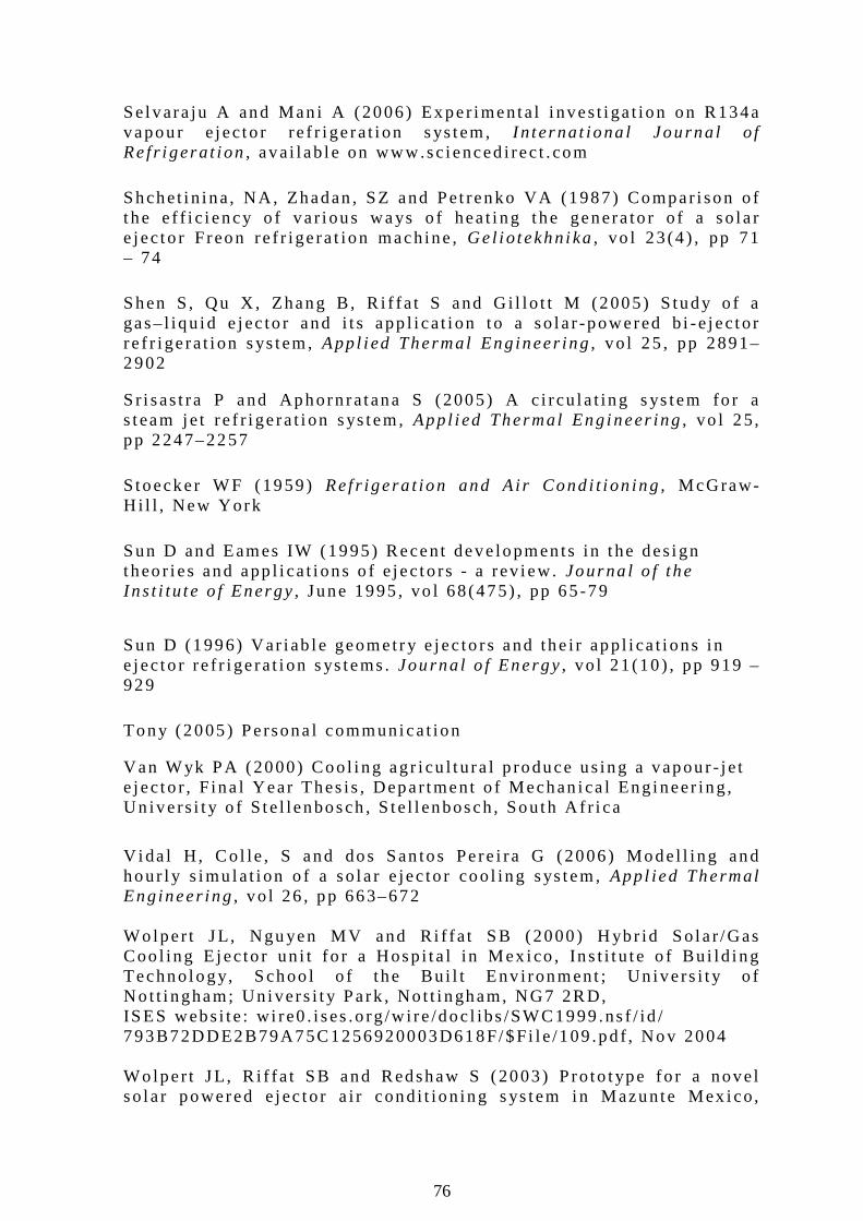
76
Se lvara ju A and Man i A (2006) Exper imenta l i nves t i ga t ion on R134a vapour e jec to r re f r i ge ra t i on s ys tem, I n terna t iona l Jou rna l o f Re f r i gera t i on, ava i l ab le on www.sc ienced i rec t . com
Shchet i n ina, NA, Zhadan , SZ and Pet renko VA (1987) Compar i son o f t he e f f i c i ency o f va r i ous ways o f hea t i ng the genera to r o f a so la r e jec to r F reon re f r ige ra t ion mach ine , Gel io tekhn i ka, vo l 23 (4 ) , pp 71 – 74
Shen S , Qu X , Zhang B , R i f fa t S and G i l lo t t M (2005) S tudy o f a gas– l iqu id e jec to r and i t s app l i ca t i on to a so la r -powered b i -e jec to r re f r i ge ra t i on s ys tem, Appl i ed Thermal Eng ineer ing, vo l 25 , pp 2891–2902 Sr i sas t ra P and Aphorn ra tana S (2005) A c i r cu la t ing s ys tem fo r a s team je t re f r i ge ra t i on sys tem, Appl i ed Thermal Eng ineer ing, vo l 25, pp 2247–2257
Stoecker WF (1959) Ref r ige ra t ion and A i r Cond i t i on ing , McGraw-H i l l , New York
Sun D and Eames IW (1995) Recent deve lopmen ts in t he des ign theo r ies and app l i ca t i ons o f e jec to rs - a rev iew. Journa l o f the Ins t i tu te o f Energy, June 1995 , vo l 68 (475) , pp 65 -79
Sun D (1996) Var iab le geomet r y e jec to rs and the i r app l i ca t i ons in e jec to r re f r i ge ra t i on s ys tems . Journa l o f Energy, vo l 21 (10 ) , pp 919 – 929
Tony (2005) Persona l communica t ion Van Wyk PA (2000) Coo l i ng agr i cu l t u ra l p roduce us ing a vapour - j e t e jec to r , F ina l Year Thes is , Depar tment o f Mechan ica l Eng ineer ing , Un ive rs i t y o f S te l lenbosch , S te l l enbosch, South A f r i ca
Vida l H, Co l le , S and dos San tos Pere i ra G (2006) Model l ing and hour l y s imu la t i on o f a so la r e jec to r coo l ing sys tem, Appl ied Thermal Eng ineer ing, vo l 26 , pp 663–672 Wo lper t J L, Ngu yen MV and R i f fa t SB (2000) H ybr id So la r /Gas Coo l ing E jec to r un i t f o r a Hosp i ta l in Mex i co , Ins t i t u te o f Bu i ld ing Techno logy, Schoo l o f the Bu i l t Env i ronment ; Un ive rs i t y o f No t t i ngham; Un ivers i t y Park , No t t i ngham, NG7 2RD, ISES webs i te : w i re0 . i ses .o rg /w i re /doc l ibs /SWC1999 .ns f / id / 793B72DDE2B79A75C1256920003D618F/$Fi l e /109 .pd f , Nov 2004 Wo lper t J L, R i f fa t SB and Redshaw S (2003) P ro to t ype fo r a nove l so la r powered e jec to r a i r cond i t ion ing s ys tem in Mazunte Mex ico,

77
Un ive rs i t y o f N o t t i ngham, Ins t i t u te o f Bu i l d ing Techno logy, No t t i ngham, Un i ted K ingdom, Proceed ing o f the In terna t i ona l So la r Energy Congress 2003, Gothenburg APPENDIX A – ADDITIONAL TABLES
Tab le A .1 : Exper imenta l resu l ts (Eames e t a l . , 1995b)
Te [°C] Tb [°C] Tc [°C] Pc [kPa] COPelec COPwater COPtheo
5 120 26.5 3.45 0.239 0.404 0.508 5 125 27.8 3.75 0.197 0.344 0.466 5 130 30.8 4.46 0.157 0.276 0.365 5 135 33.4 5.17 0.127 0.251 0.316 5 140 34.4 5.47 0.102 0.178 0.277
7.5 120 27.3 3.65 0.306 0.500 0.597 7.5 125 29.5 4.16 0.250 0.419 0.505 7.5 130 31.5 4.66 0.207 0.355 0.436 7.5 135 33.4 5.17 0.173 0.297 0.379 7.5 140 35.3 5.78 0.138 0.233 0.328
10 120 28.3 3.85 0.369 0.586 0.685 10 125 30.0 4.26 0.328 0.537 0.607 10 130 31.9 4.76 0.288 0.473 0.530 10 135 34.0 5.37 0.237 0.389 0.454 10 140 36.3 6.08 0.188 0.309 0.382
Tab le A .2 : Geomet r i es o f d i f fe ren t nozz les
Geometries[mm]
Nozzle number A B C D E
1 1.5 6 69.25 8 25.75 2 1.75 7 65.00 8 30.00 3 2.0 8 60.70 8 34.30 4 2.5 8 60.70 8 34.30 5 2.5 10 42.85 8 52.15 6 3.0 12 51.50 8 43.50 7 3.5 14 60.00 8 35.00
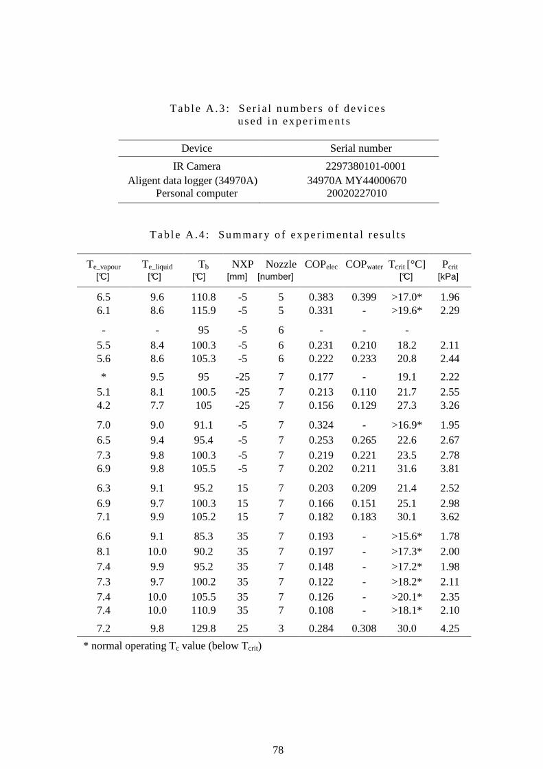
78
Tab le A .3 : Ser ia l numbers o f dev i ces used i n exper iments
Device Serial number
IR Camera 2297380101-0001 Aligent data logger (34970A) . 34970A MY44000670
Personal computer 20020227010
Tab le A .4 : Summary o f ex per imenta l resu l t s
Te_vapour Te_liquid Tb NXP Nozzle COPelec COPwater Tcrit [°C] Pcrit [°C] [°C] [°C] [mm] [number] [°C] [kPa]
6.5 9.6 110.8 -5 5 0.383 0.399 >17.0* 1.96 6.1 8.6 115.9 -5 5 0.331 - >19.6* 2.29
- - 95 -5 6 - - - 5.5 8.4 100.3 -5 6 0.231 0.210 18.2 2.11 5.6 8.6 105.3 -5 6 0.222 0.233 20.8 2.44
* 9.5 95 -25 7 0.177 - 19.1 2.22 5.1 8.1 100.5 -25 7 0.213 0.110 21.7 2.55 4.2 7.7 105 -25 7 0.156 0.129 27.3 3.26
7.0 9.0 91.1 -5 7 0.324 - >16.9* 1.95 6.5 9.4 95.4 -5 7 0.253 0.265 22.6 2.67 7.3 9.8 100.3 -5 7 0.219 0.221 23.5 2.78 6.9 9.8 105.5 -5 7 0.202 0.211 31.6 3.81
6.3 9.1 95.2 15 7 0.203 0.209 21.4 2.52 6.9 9.7 100.3 15 7 0.166 0.151 25.1 2.98 7.1 9.9 105.2 15 7 0.182 0.183 30.1 3.62
6.6 9.1 85.3 35 7 0.193 - >15.6* 1.78 8.1 10.0 90.2 35 7 0.197 - >17.3* 2.00 7.4 9.9 95.2 35 7 0.148 - >17.2* 1.98 7.3 9.7 100.2 35 7 0.122 - >18.2* 2.11 7.4 10.0 105.5 35 7 0.126 - >20.1* 2.35 7.4 10.0 110.9 35 7 0.108 - >18.1* 2.10
7.2 9.8 129.8 25 3 0.284 0.308 30.0 4.25
* normal operating Tc value (below Tcrit)
79
APPENDIX B – ADDITIONAL PHOTOS/FIGURES
F igu re B.1 : P rev ious e jec to r se tup a t S te l l enbosch Un ivers i t y
F igu re B.2 : Exper imenta l se tups f rom o ther au thors (Aphorn ra tana
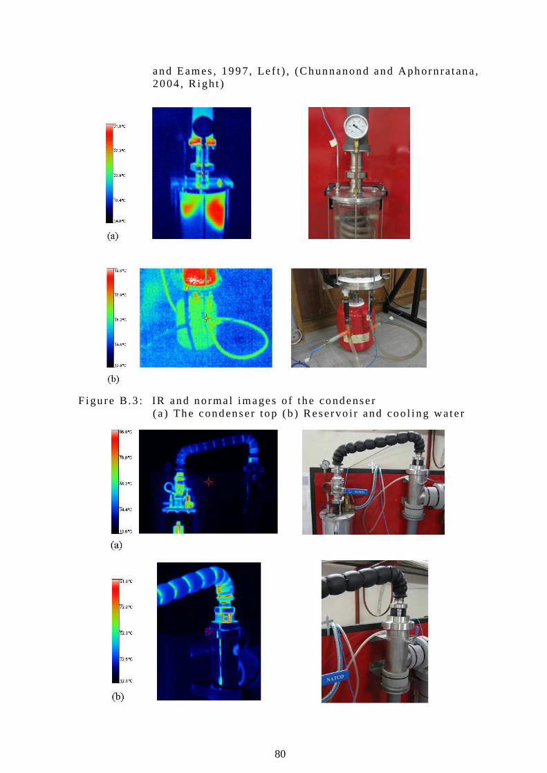
80
and Eames , 1997, Le f t ) , (Chunnanond and Aphorn ra tana , 2004 , R igh t )
F igu re B.3 : IR and norma l images o f the condenser
(a ) The condenser top (b ) Reservo i r and coo l i ng wate r
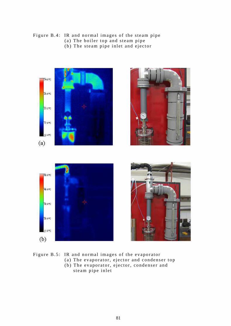
81
F igu re B.4 : IR and norma l images o f the s team p ipe
(a ) The bo i l e r top and s team p ipe (b ) The s team p ipe i n le t and e jec to r
F igu re B.5 : IR and norma l images o f the evaporator
(a ) The evapora tor , e jec to r and condenser t op (b ) The evaporato r , e jec to r , condenser and s team p ipe in le t
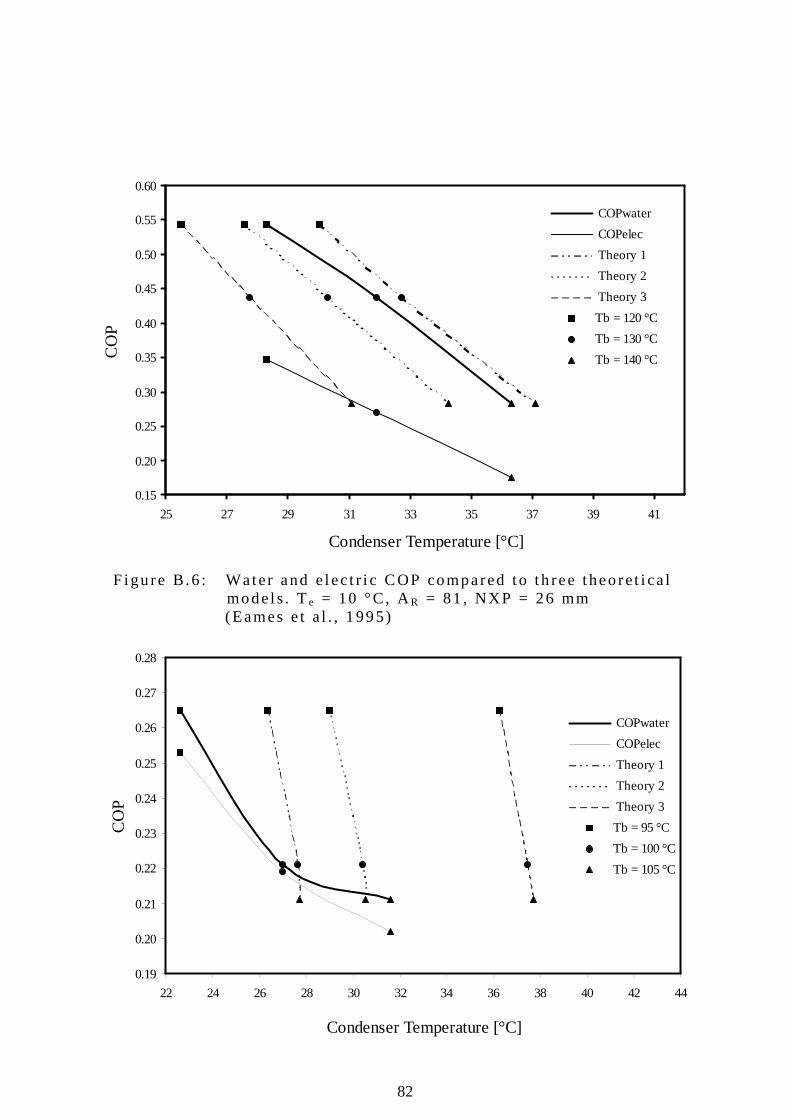
82
0.15
0.20
0.25
0.30
0.35
0.40
0.45
0.50
0.55
0.60
25 27 29 31 33 35 37 39 41
Condenser Temperature [°C]
CO
P
COPwater
COPelec
Theory 1
Theory 2
Theory 3
Tb = 120 °C
Tb = 130 °C
Tb = 140 °C
0.19
0.20
0.21
0.22
0.23
0.24
0.25
0.26
0.27
0.28
22 24 26 28 30 32 34 36 38 40 42 44
Condenser Temperature [°C]
CO
P
COPwater
COPelec
Theory 1
Theory 2
Theory 3
Tb = 95 °C
Tb = 100 °C
Tb = 105 °C
F igu re B.6 : Water and e lec t r i c COP compared to t h ree theo re t i ca l models . Te = 10 °C, AR = 81 , NXP = 26 mm
(Eames e t a l . , 1995)
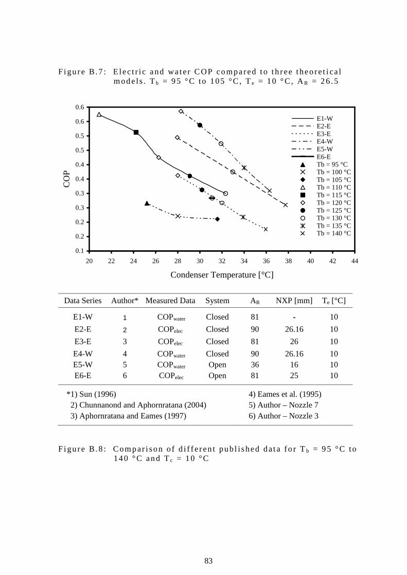
83
0.1
0.2
0.2
0.3
0.3
0.4
0.4
0.5
0.5
0.6
0.6
20 22 24 26 28 30 32 34 36 38 40 42 44
Condenser Temperature [°C]
CO
P
E1-W E2-E E3-E E4-W E5-W E6-E Tb = 95 °C Tb = 100 °C Tb = 105 °C Tb = 110 °C Tb = 115 °C Tb = 120 °C Tb = 125 °C Tb = 130 °C Tb = 135 °C Tb = 140 °C
F igu re B.7 : E lec t r i c and wa ter COP compared to t h ree theo re t i ca l mode ls . Tb = 95 °C to 105 °C, Te = 10 °C, AR = 26 .5
Data Series Author* Measured Data System AR NXP [mm] Te [°C]
E1-W 1 COPwater Closed 81 - 10
E2-E 2 COPelec Closed 90 26.16 10
E3-E 3 COPelec Closed 81 26 10
E4-W 4 COPwater Closed 90 26.16 10 E5-W 5 COPwater Open 36 16 10 E6-E 6 COPelec Open 81 25 10
*1) Sun (1996) 4) Eames et al. (1995) 2) Chunnanond and Aphornratana (2004) 5) Author – Nozzle 7 3) Aphornratana and Eames (1997) 6) Author – Nozzle 3
F igu re B.8 : Compar i son o f d i f fe ren t pub l i shed data fo r Tb = 95 °C to 140 °C and Tc = 10 °C
84
APPENDIX C – EXPERIMENTAL SETUP DRAWING TREE : Steam Je t E jec to r Comple te Assembly (S teamJet06_00_00A)* * Bo i l e r Assembly (S teamJet06_01_00A) Ma in Bo i l e r P ipe (S teamJ et06_01_01P)* F lange (S teamJet06_01_02P)* F lange (S teamJet06_01_03P)* Ma le Un ion (S teamJet06_01_04P)* P ipe (S teamJet06_01_05P)* F lange (S teamJet06_01_06P)* Condenser Assembly (S teamJet06_02_00A) P ipe (S teamJet06_02_01P)* F lange (S teamJet06_02_02P)* F lange (S teamJet06_02_03P)* P ipe (S teamJet06_01_05P)* Un ion (S teamJ et06_01_04P)* Evapora tor Assembly (S teamJet06_03_00A) P ipe (S teamJet06_03_01P)* P ipe (S teamJet06_03_02P)* F lange (S teamJet06_03_03P)* F lange (S teamJet06_03_04P)* F lange (S teamJet06_03_05P)* E lbow (S teamJ et06_03_06P)* Un ion (S teamJ et06_03_07P)* Steam Pipe Assembly (S teamJet06_04_00A) P ipe (S teamJet06_04_01P)* E lbow (S teamJ et06_04_02P)* Un ion (S teamJ et06_01_04P)* E lbow (S teamJ et06_04_03P)* P ipe (S teamJet06_01_05P)* E lbow (S teamJ et06_04_04P)* Un ion (S teamJ et06_04_05P)*
Ejec to r Assembly (S teamJet06_05_00A) E jec to r (S teamJet06_05_01P) F lange (S teamJet06_05_02P)* F lange (S teamJet06_05_03P)* Un ion (S teamJ et06_05_04P)* F lange (S teamJet06_05_05P)* P ipe (S teamJet06_01_05P)* Un ion (S teamJ et06_04_05P)* T -P iece (S teamJ et06_05_06P)*
Ejec to r Top Assemb ly (S teamJet06_06_00A) F lange (S teamJet06_06_01P)*

85
Spacer (S teamJet06_06_05P)* Spacer (S teamJet06_06_04P)* Nozz le (S teamJet06_06_13P)* Un ion (S teamJ et06_05_04P)* P ipe (S teamJet06_01_05P)* Un ion (S teamJ et06_04_05P)* Add i t i ona l pa r ts Nozz le (S teamJet06_06_11P) Nozz le (S teamJet06_06_12P) Nozz le (S teamJet06_06_13P) Nozz le (S teamJet06_06_14P) Nozz le (S teamJet06_06_15P) Nozz le (S teamJet06_06_16P) Nozz le (S teamJet06_06_17P) Spacer (S teamJet06_06_04P)* Spacer (S teamJet06_06_05P)* Spacer (S teamJet06_06_06P)* Spacer (S teamJet06_06_07P)* Spacer (S teamJet06_06_08P)* Spacer (S teamJet06_06_09P)* Spacer (S teamJet06_06_10P)* *These par ts are i nc luded on the data CD a t t he back o f th is t hes i s . * *The l e t t e r A a t t he end o f a par t number ind i ca tes tha t i t i s an assemb ly. The l e t t e r P i nd ica tes that i t i s a par t .