std spec for building works 2014
TRANSCRIPT

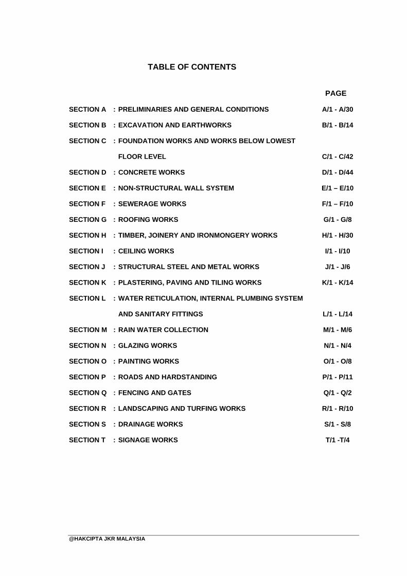
TABLE OF CONTENTS PAGE
@HAKCIPTA JKR MALAYSIA
SECTION A : PRELIMINARIES AND GENERAL CONDITIONS
SECTION B : EXCAVATION AND EARTHWORKS
SECTION C : FOUNDATION WORKS AND WORKS BELOW LOWEST
FLOOR LEVEL
SECTION D : CONCRETE WORKS
SECTION E : NON-STRUCTURAL WALL SYSTEM
SECTION F : SEWERAGE WORKS
SECTION G : ROOFING WORKS
SECTION H : TIMBER, JOINERY AND IRONMONGERY WORKS
SECTION I : CEILING WORKS
SECTION J : STRUCTURAL STEEL AND METAL WORKS
SECTION K : PLASTERING, PAVING AND TILING WORKS
SECTION L : WATER RETICULATION, INTERNAL PLUMBING SYSTEM
AND SANITARY FITTINGS
SECTION M : RAIN WATER COLLECTION
SECTION N : GLAZING WORKS
SECTION O : PAINTING WORKS
SECTION P : ROADS AND HARDSTANDING
SECTION Q : FENCING AND GATES
SECTION R : LANDSCAPING AND TURFING WORKS
SECTION S : DRAINAGE WORKS
SECTION T : SIGNAGE WORKS
A/1 - A/30
B/1 - B/14
C/1 - C/42
D/1 - D/44
E/1 – E/10
F/1 – F/10
G/1 - G/8
H/1 - H/30
I/1 - I/10
J/1 - J/6
K/1 - K/14
L/1 - L/14
M/1 - M/6
N/1 - N/4
O/1 - O/8
P/1 - P/11
Q/1 - Q/2
R/1 - R/10
S/1 - S/8
T/1 -T/4

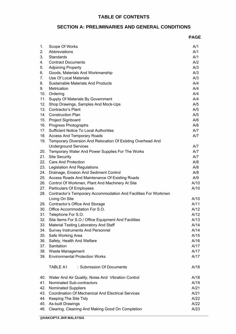
TABLE OF CONTENTS
SECTION A: PRELIMINARIES AND GENERAL CONDITIONS PAGE
@HAKCIPTA JKR MALAYSIA
1. Scope Of Works 2. Abbreviations 3. Standards 4. Contract Documents 5. Adjoining Property 6. Goods, Materials And Workmanship 7. Use Of Local Materials 8. Sustainable Materials And Products 9. Metrication 10. Ordering 11. Supply Of Materials By Government 12. Shop Drawings, Samples And Mock-Ups 13. Contractor’s Plant 14. Construction Plan 15. Project Signboard 16. Progress Photographs 17. Sufficient Notice To Local Authorities 18. Access And Temporary Roads 19. Temporary Diversion And Relocation Of Existing Overhead And
Underground Services 20. Temporary Water And Power Supplies For The Works 21. Site Security 22. Care And Protection 23. Legislation And Regulations 24. Drainage, Erosion And Sediment Control 25. Access Roads And Maintenance Of Existing Roads 26. Control Of Workmen, Plant And Machinery At Site 27. Particulars Of Employees 28. Contractor’s Temporary Accommodation And Facilities For Workmen
Living On Site 29. Contractor’s Office And Storage 30. Office Accommodation For S.O. 31. Telephone For S.O. 32. Site Items For S.O./ Office Equipment And Facilities 33. Material Testing Laboratory And Staff 34. Survey Instruments And Personnel 35. Safe Working Area 36. Safety, Health And Welfare 37. Sanitation 38. Waste Management 39. Environmental Protection Works
TABLE A1 : Submission Of Documents
40. Water And Air Quality, Noise And Vibration Control 41. Nominated Sub-contractors 42. Nominated Suppliers 43. Coordination Of Mechanical And Electrical Services 44. Keeping The Site Tidy 45. As-built Drawings 46. Clearing, Cleaning And Making Good On Completion
A/1 A/1 A/1 A/2 A/3 A/3 A/3 A/4 A/4 A/4 A/4 A/5 A/5 A/5 A/6 A/6 A/7 A/7
A/7 A/7 A/7 A/8 A/8 A/8 A/9 A/10 A/10
A/10 A/11 A/12 A/12 A/13 A/14 A/14 A/15 A/16 A/17 A/17 A/17
A/18
A/18 A/19 A/21 A/21 A/22 A/22 A/23

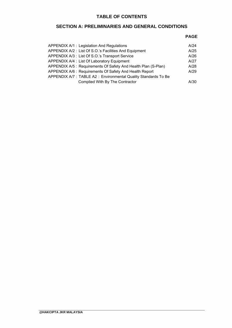
TABLE OF CONTENTS
SECTION A: PRELIMINARIES AND GENERAL CONDITIONS PAGE
@HAKCIPTA JKR MALAYSIA
APPENDIX A/1 : Legislation And Regulations APPENDIX A/2 : List Of S.O.’s Facilities And Equipment APPENDIX A/3 : List Of S.O.’s Transport Service APPENDIX A/4 : List Of Laboratory Equipment APPENDIX A/5 : Requirements Of Safety And Health Plan (S-Plan) APPENDIX A/6 : Requirements Of Safety And Health Report APPENDIX A/7 : TABLE A2 : Environmental Quality Standards To Be
Complied With By The Contractor
A/24 A/25 A/26 A/27 A/28 A/29
A/30


JKR MALAYSIA
SECTION A: PRELIMINARIES AND GENERAL CONDITIONS
No. DokumenNo. KeluaranNo. PindaanTarikhMuka Surat
: : : : :
JKR 20800-0183-1401 00 29 Januari 2014 A/1
@HAKCIPTA JKR MALAYSIA
1. Scope Of Works 1.1 The Works covered in this Contract comprise the provision by the Contractor at his
own risk and cost of all materials, scaffolding, tools, plant, labour, transport, water, light and everything else necessary for the construction and completion of i.………… ………………………………………………………….……all to the approval of the S.O.
1.2 The Conditions of Contract for the Works, which is embodied in the Form of Contract (Form PWD 203 / Form PWD 203A), shall be read in conjunction with this Specification. A copy of the Form of Contract is available for inspection on the Tender Table on any working day up to the time appointed for receiving tenders. If the tenderer considers that any of the clauses of the Contract involves expenses, he shall allow for the money value of such clauses in his Tender.
2. Abbreviations
2.1 The following abbreviations appearing in these Specifications have their meanings
as assigned against them:
(i) B.Q. - Bills of Quantities (ii) CIAST - Pusat Latihan Pengajar dan Kemahiran Lanjutan (iii) CIDB - Construction Industry Development Board (iv) CoW - Clerk of Works (v) DGFR - Director General of Fire and Rescue (vi) DOE - Department of Environment (vii) DOSH - Department of Occupational Safety and Health (viii) EMP - Environmental Management Plan (ix) JKR - Jabatan Kerja Raya (x) MOH - Ministry of Health (xi) MSMA - Manual Saliran Mesra Alam (xii) MTIB - Malaysian Timber Industry Board (xiii) PDRM - Polis Diraja Malaysia (xiv) P.E. - Professional Engineer (xv) R.O.W. - Right Of Way (xvi) S.O. - Superintending Officer (xvii) S.P. - System Provider (xviii) SIRIM - Standards and Industrial Research Institute of Malaysia (xix) SPAN - Suruhanjaya Perkhidmatan Air Negara
3. Standards 3.1 All Standards referred to in this Specification together with any addenda issued shall
be deemed to be the editions current at the time of Tender. If the Malaysian Standard (MS) exists, which the S.O. deems to be equivalent to the British or other Standard specified, then the MS shall be followed. Other equivalent standards specifying superior material may be used with the approval of the S.O.
3.2 In the event of any discrepancy between the provision of this Specification and the provision within the relevant Standards or Codes of Practice (CP) as mentioned in this Specification, then the provision of this Specification shall take precedence.
i Refer to details in the B.Q./Summary of Tender
JKR MALAYSIA
SECTION A: PRELIMINARIES AND GENERAL CONDITIONS
No. DokumenNo. KeluaranNo. PindaanTarikhMuka Surat
: : : : :
JKR 20800-0183-1401 00 29 Januari 2014 A/2
@HAKCIPTA JKR MALAYSIA
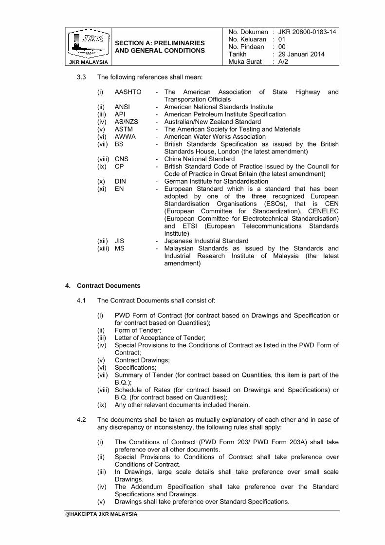
3.3 The following references shall mean:
(i) AASHTO - The American Association of State Highway and Transportation Officials
(ii) ANSI - American National Standards Institute (iii) API - American Petroleum Institute Specification (iv) AS/NZS - Australian/New Zealand Standard (v) ASTM - The American Society for Testing and Materials (vi) AWWA - American Water Works Association (vii) BS - British Standards Specification as issued by the British
Standards House, London (the latest amendment) (viii) CNS - China National Standard (ix) CP - British Standard Code of Practice issued by the Council for
Code of Practice in Great Britain (the latest amendment) (x) DIN - German Institute for Standardisation (xi) EN - European Standard which is a standard that has been
adopted by one of the three recognized European Standardisation Organisations (ESOs), that is CEN (European Committee for Standardization), CENELEC (European Committee for Electrotechnical Standardisation) and ETSI (European Telecommunications Standards Institute)
(xii) JIS - Japanese Industrial Standard (xiii) MS - Malaysian Standards as issued by the Standards and
Industrial Research Institute of Malaysia (the latest amendment)
4. Contract Documents 4.1 The Contract Documents shall consist of:
(i) PWD Form of Contract (for contract based on Drawings and Specification or
for contract based on Quantities); (ii) Form of Tender; (iii) Letter of Acceptance of Tender; (iv) Special Provisions to the Conditions of Contract as listed in the PWD Form of
Contract; (v) Contract Drawings; (vi) Specifications; (vii) Summary of Tender (for contract based on Quantities, this item is part of the
B.Q.); (viii) Schedule of Rates (for contract based on Drawings and Specifications) or
B.Q. (for contract based on Quantities); (ix) Any other relevant documents included therein.
4.2 The documents shall be taken as mutually explanatory of each other and in case of any discrepancy or inconsistency, the following rules shall apply: (i) The Conditions of Contract (PWD Form 203/ PWD Form 203A) shall take
preference over all other documents. (ii) Special Provisions to Conditions of Contract shall take preference over
Conditions of Contract. (iii) In Drawings, large scale details shall take preference over small scale
Drawings. (iv) The Addendum Specification shall take preference over the Standard
Specifications and Drawings. (v) Drawings shall take preference over Standard Specifications.
JKR MALAYSIA
SECTION A: PRELIMINARIES AND GENERAL CONDITIONS
No. DokumenNo. KeluaranNo. PindaanTarikhMuka Surat
: : : : :
JKR 20800-0183-1401 00 29 Januari 2014 A/3
@HAKCIPTA JKR MALAYSIA
4.3 Any discrepancies shall be referred as soon as possible to the S.O. who shall decide which shall be followed.
5. Adjoining Property Where the property adjoining the Site is in constant use by the Employer/adjoining owners and occupiers, the Contractor shall arrange and carry out the Works so as to cause minimum interference or interruption to the use of adjoining properties including roads, footpaths, other access and any existing services thereto. He shall comply with all instructions or directions given by the S.O. in these matters.
6. Goods, Materials And Workmanship 6.1 Materials and workmanship throughout the Works shall be in accordance with the
Drawings and Specifications and to the approval of the S.O.
6.2 Where required, all works shall be executed by competent and skilled workers in the related field.
6.3 Wherever in this Specification any proprietary goods or materials are specified,
goods or materials of alternative manufacture may be considered for acceptance provided they comply in all respect as regards to appearance and quality, and are approved by the S.O.
6.4 If, however, the Contractor has shown beyond reasonable doubt that the specified goods or materials cannot be obtained and the S.O. is satisfied with regard to the non-availability of the goods and materials, the benefit of cost savings, if any, resulting from the Contractor’s proposal or substitution of goods or materials approved by the S.O., shall be deducted from the Contract Sum.
7. Use Of Local Materials 7.1 The Contractor shall use locally manufactured materials and goods as listed in the
‘Senarai Bahan/Barangan Binaan Buatan Tempatan’ issued by IKRAM QA Services Sdn. Bhd. and/or ‘Senarai Bahan/Barangan Buatan Tempatan’ issued by SIRIM QA Services Sdn. Bhd., whichever is relevant. If the Contractor fails to comply with this requirement, a penalty shall be imposed and/or the materials supplied shall be rejected.
7.2 The locally manufactured materials and goods which are not listed aforesaid, may
be permitted if the materials have been tested and certified by IKRAM QA Services Sdn. Bhd. or SIRIM QA Services Sdn. Bhd. whichever is relevant. If the testing cannot be carried out by IKRAM QA Services Sdn. Bhd. or SIRIM QA Services Sdn. Bhd., the Contractor may apply and, subject to the approval of the S.O., carry out the testing by other agencies.
7.3 Under no circumstances will the Contractor be permitted to incorporate or supply
imported materials, plant, equipment, or other goods into the Works or forming part of the scope of the Works except those approved by the Government, prior to the execution of the Contract. The Contractor shall substitute any materials, plant, equipment, or other goods proposed to be imported but not approved by the Government, with suitable local materials, plant, equipment, or other goods, including making any necessary sub-sequential changes or adjustments to the design of the Works to accommodate such substitution, all to the concurrence of the S.O.
JKR MALAYSIA
SECTION A: PRELIMINARIES AND GENERAL CONDITIONS
No. DokumenNo. KeluaranNo. PindaanTarikhMuka Surat
: : : : :
JKR 20800-0183-1401 00 29 Januari 2014 A/4
@HAKCIPTA JKR MALAYSIA
7.4 The Contractor shall ensure that the procurement of approved imported materials, plant, equipment, or other goods are obtained directly from the country of origin based on Free On Board (F.O.B) or other similar basis. The transportation and insurance of such imported materials, plant, equipment, or other goods from the country of origin to the Site shall be arranged by the Contractor through approved Government’s Multi Modal Transport Operators (MTO). The Contractor shall allow in his tender all costs and time required in complying with the requirements of this clause including the cost required for the services provided by the MTO.
7.5 The Contractor shall submit documentary evidence of compliance with this clause to
the S.O. within one (1) month from the date of each delivery to the Site of such materials, plant, equipment, vehicles or other goods.
8. Sustainable Materials And Products 8.1 Notwithstanding the materials and products shown on the Drawings or specified
herewith, the Contractor is encouraged to propose, at no additional cost, alternative equivalent materials or “Green” products to be used in the Works, subject to the approval of the S.O., such as:
(i) Environmentally friendly materials or “Green” products that are certified under
the SIRIM Eco-Label certification or any labels under the Global Eco-Label Network (GEN) certification.
(ii) Products self-declared “Green” by the manufacturer with certification from recognised independent certifying bodies and not a member of GEN.
9. Metrication Unless otherwise specified hereinafter or shown on the Drawings, only materials of metric dimension shall be used for the Works. Materials of equivalent imperial dimension may only be used if the Contractor can satisfy the S.O. that the required materials are not available in metric dimension.
10. Ordering
The Contractor shall place his orders for specified materials at the earliest possible date after notification of acceptance of tender or at such times as may be specifically stated for any particular material.
11. Supply Of Materials By Government 11.1 If the Contractor fails for any reason to supply any materials, which he has
contracted to supply, or if he fails to supply any such materials in sufficient time to enable the Contract to be completed by the agreed date for completion, the Government may supply any portion, or all of such materials.
11.2 If the Government supplies such material, the cost in respect thereof to be borne by
the Contractor shall be either the current market rates or the actual cost to the Government, whichever is greater, plus 5% on cost charges.
11.3 The cost to be borne by the Contractor, as detailed above, shall be deducted from
any money due or to become due to the Contractor under this Contract and failing which such costs shall be recovered from the Performance Bond or as a debt due from the Contractor.
JKR MALAYSIA
SECTION A: PRELIMINARIES AND GENERAL CONDITIONS
No. DokumenNo. KeluaranNo. PindaanTarikhMuka Surat
: : : : :
JKR 20800-0183-1401 00 29 Januari 2014 A/5
@HAKCIPTA JKR MALAYSIA
11.4 No action by the S.O. under this clause shall be deemed in any way to affect or modify the right of the Government to claim for damages in the event of the Contractor’s failure to complete the Works by the agreed date of completion.
12. Shop Drawings, Samples And Mock-ups
12.1 The Contractor shall submit for approval relevant shop drawings as requested by
the S.O.
12.2 The Contractor shall submit samples of materials or execute samples of workmanship for the S.O.’s approval, and for further samples as required until the samples submitted or executed are in accordance with this Specification.
12.3 The Contractor shall prepare sample installations as required to match specified works in all respects before proceeding with work. Mock-up units approved and accepted by the S.O. shall be referred as the Standard of comparison for the work.
12.4 The Contractor shall submit for approval as requested by the S.O., manufacturer's specifications, installation instruction, general recommendation for the work, including certified laboratory test reports and other data required to show compliance with these specifications.
13. Contractor’s Plant
13.1 The Contractor shall provide, erect, keep insured, maintain and remove on
completion all requisite scaffolding, hoist, ladder, staging, tarpaulins, tools, vehicles, tackles and other plants and apparatus (excluding piling and pile testing equipment), as required by all trades as are necessary for the execution of the Works.
13.2 All mechanical plant used by the Contractor shall be of such type, size and capacity suitable to the type and nature of the Works and site conditions where the Works are to be executed.
13.3 The Contractor shall take note the required cranage for the erection and completion of precast components and to ensure that the said cranes are or will be available during the construction stages.
14. Construction Plan
14.1 Within fourteen (14) days after the receipt of the Letter of Acceptance, the Contractor shall submit to the S.O. for his approval the following: 14.1.1 Programme of Works
14.1.1.1 A detailed work programme using the Critical Path Method (CPM) including electronic and printed copies of all data. The programme shall be presented in the form of Gantt chart and network diagrams indicating, among others the critical activities, interface dates and resources required to complete the works within the Contract period. The Contractor shall be required to update all information and maintain the planned programme weekly/monthly using the CPM or as instructed by the S.O.
14.1.1.2 The work programme shall be prepared and maintained by
trained and qualified personnel.
JKR MALAYSIA
SECTION A: PRELIMINARIES AND GENERAL CONDITIONS
No. DokumenNo. KeluaranNo. PindaanTarikhMuka Surat
: : : : :
JKR 20800-0183-1401 00 29 Januari 2014 A/6
@HAKCIPTA JKR MALAYSIA
14.1.2 Method statements
14.1.2.1 The Contractor shall also furnish in writing to the S.O. or S.O’s Representatives particulars of the Contractor’s method statements for carrying out such works and of the construction plant and temporary works, if any, which the Contractor intends to supply, use or construct as the case may be. The submission to and approval by the S.O. or the S.O.’s Representatives of such programme or the furnishing of such particulars shall not relieve the Contractor of any of his duties or responsibilities under the Contract.
14.1.2.2 If at any time it should appear to the S.O that the actual
progress of the Works does not conform to the approved programme the Contractor shall submit for approval, a revised programme showing the modifications to the previously approved programme and additional resources necessary to ensure the completion of the whole Works within the approved contract period.
14.1.3 Contractor’s organisation chart
The Contractor shall submit to the S.O. the organisation chart of his project team showing the personnel involved, their designations and relationship including their roles and responsibilities.
14.1.4 Schedules
14.1.4.1 The Contractor shall submit the following schedules:
(i) Maintenance and Calibration Schedule of the plant and equipment to be used in the Works.
(ii) Inspection and Testing Schedule of the plant and equipment, itemising the type and frequency of inspection and testing.
15. Project Signboard
The Contractor shall provide, erect, paint and maintain a project signboard in Bahasa Melayu as shown on the relevant drawing or as directed by the S.O. The signboard shall be erected at a prominent position at the Site as approved by the S.O.
16. Progress Photographs
16.1 The Contractor shall take progress photographs at monthly intervals or more frequent as directed by the S.O. The photographs to be taken from different angles as approved by the S.O. and the average number of photographs shall be sufficient enough to show the progress of the Works. For building works, the average number per month shall not be less than six (6) per block of building.
16.2 The Contractor shall supply six (6) sets of bound printed copies of the approved photographs, all properly titled and dated. The photographs shall also be provided in jpeg or other approved format with each image set at minimum size of 1280 x 960 pixels and at resolution of 72 pixels per inch and submitted to the S.O. monthly, in compact discs or removable storage.
JKR MALAYSIA
SECTION A: PRELIMINARIES AND GENERAL CONDITIONS
No. DokumenNo. KeluaranNo. PindaanTarikhMuka Surat
: : : : :
JKR 20800-0183-1401 00 29 Januari 2014 A/7
@HAKCIPTA JKR MALAYSIA
17. Sufficient Notice To Local Authorities/Utility Providers/Regulatory Bodies 17.1 The Contractor shall give sufficient notice to the relevant Local Authorities/Utility
Providers/Regulatory Bodies before commencing or to inspect any works in relation to their scope of services. Failure to give sufficient notice shall not entitle the Contractor to extension of time due to any subsequent delays in connection with the Works.
17.2 Any notice given to the above mentioned authorities shall also be copied to the S.O.
18. Access And Temporary Roads The Contractor shall provide and maintain all necessary temporary entrance to the Site and temporary culverts, tracks, bridges, et cetera for access to and within the Site as long as required to the approval of the S.O. The position where the site access is to be made shall be as indicated on the site plan or as approved by the S.O. and the Contractor shall make all arrangements and obtain all approvals and permissions required at his own cost.
19. Temporary Diversion And Relocation Of Existing Overhead And Underground
Services 19.1 Before commencing any excavation, et cetera, the Contractor shall enquire from
the various authorities whether any underground pipes, cables, et cetera are present on the Site and if so, he shall make arrangements for the disconnection, removal and if necessary, the relocation and reconnection of such services and pay all necessary cost and fees in connection with all temporary diversion and relocation of existing services.
19.2 If during excavation, the Contractor comes across any underground cables, et
cetera, he shall immediately stop work and refer to the S.O. for further instructions and make arrangements for the disconnection, et cetera The Contractor shall be responsible for making good all damage to the cables, et cetera, and shall indemnify the Government against any claims as a result of such damage.
20. Temporary Water And Power Supplies For The Works 20.1 The Contractor shall provide adequate power supplies for temporary lighting and
for the execution of the works. Electricity shall be obtained from Tenaga Nasional Berhad (TNB) or the local electricity supply company. Where such electricity supply cannot be provided, generator set(s) may be used but safety precautions must be taken. The use of kerosene lamps shall not be allowed.
20.2 The Contractor shall provide all water required for the use in the Works including paying all associated costs and fees and providing and removing all temporary plumbing and storage facilities on completion.
21. Site Security
The Contractor shall provide all necessary personnel and lighting for the security of the site at all times until completion of the whole Works.
JKR MALAYSIA
SECTION A: PRELIMINARIES AND GENERAL CONDITIONS
No. DokumenNo. KeluaranNo. PindaanTarikhMuka Surat
: : : : :
JKR 20800-0183-1401 00 29 Januari 2014 A/8
@HAKCIPTA JKR MALAYSIA
22. Care And Protection Of Materials And Works
The Contractor shall provide and maintain everything necessary for proper protection of materials and Works from any damage by weather, carelessness or otherwise. Any damage caused shall be made good at the Contractor’s own cost to the approval of the S.O.
23. Legislation And Regulations
23.1 The Contractor shall at all times comply with the provisions of all statutes and other related legislation currently in force regarding the environment, safety and health as listed in APPENDIX A/1 including any revisions to the current regulations.
23.2 The Contractor shall be liable for and shall indemnify the Government against any
damages, expenses, liability, losses, claims, prosecution, proceedings, fines and penalties caused by any non-compliance or contravention of the above legislation and regulations.
24. Drainage, Erosion And Sediment Control
24.1 The Contractor shall execute the Erosion and Sediment Control Plan (ESCP) and all control measures as shown on the Drawings in such a manner and order as directed by the S.O. that will minimize accelerated erosion and sedimentation during the construction phase. The Contractor shall be responsible for compliance with MSMA relating to erosion and sediment control.
24.2 The Contractor shall execute ESCP which provides for inspection of erosion and
sediment control devices and facilities on a weekly basis and following precipitation events, as well as maintenance, replacement or repairs to inadequate or damaged controls and devices to ensure effective and efficient operation.
24.3 The contractor shall maintain all the temporary works regularly throughout the construction period, or as directed by the S.O. and making good of any damaged portions during the course of the works.
24.4 The Contractor shall make proper provision for the drainage of surface water from the work site including rainwater from surrounding areas which drain on to the site.
24.5 The Contractor shall provide, form, fix and maintain such pumps, chutes, walls, drains, bunds and other temporary works necessary for the proper drainage of the Site so that no ponding, flooding or other damage or disturbance is caused to areas surrounding the works throughout the duration of the Contract.
24.6 Silt/Sediment traps shall be constructed as shown on the Drawings. The silt/sediment traps shall be maintained regularly throughout the contract period, including desilting when full or as directed by the S.O. and making good of any damaged portions during the course of the Works. The desilted material shall be transported to disposal site approved by the S.O.
24.7 The Contractor shall construct construction stabilization access as shown on the Drawing unless otherwise directed by the S.O. for reducing tracking of mud and dirt onto public’s roads by Contractor’s vehicles. The construction stabilization access can be made from aggregates, asphaltic concrete and concrete based on longevity, required performance and site condition. The use of asphalt concrete grindings for stabilized construction access/roadway shall be not allowed. Stabilized construction access shall be maintained by the Contractor until
JKR MALAYSIA
SECTION A: PRELIMINARIES AND GENERAL CONDITIONS
No. DokumenNo. KeluaranNo. PindaanTarikhMuka Surat
: : : : :
JKR 20800-0183-1401 00 29 Januari 2014 A/9
@HAKCIPTA JKR MALAYSIA
construction staging requires removal or upon final stabilization of the construction site. Upon removal of the stabilized construction access, the area shall be graded and stabilized.
24.8 The Contractor shall construct wash trough as shown on the Drawing unless
otherwise directed by the S.O. for cleaning all debris, dirt and mud from the wheels and tyres of Contractor’s vehicles leaving the Site. The position of the wash trough shall be as indicated on the site plan or as approved by the S.O. The wash trough shall be maintained regularly throughout the contract period as directed by the S.O.
24.9 The Contractor shall construct temporary waterway crossing as shown on the
Drawing unless otherwise directed by the S.O., for providing erosion-free access point across a waterway for contractor’s vehicles or equipment and may be necessary to prevent contractor’s equipment from causing erosion of the waterway and tracking of pollutants into the waterway.
24.10 The Contractor shall install check dam as shown on the Drawings unless otherwise
directed by the S.O., for preventing erosion by reducing the velocity of storm water flows in diversion channel in steep terrain. The check dam shall be constructed of rocks or logs which are secured against damage during significant floods. It shall be of sufficient height and spacing to allow small pools to form between each one and also promote sedimentation behind the dam. The check dam shall be inspected after each rainfall and when a sediment accumulation of approximately one third (1/3) of the check dam height is observed, the sediment shall be removed.
24.11 The Contractor shall construct protection works to the drainage inlets and outlets
as shown on the Drawings unless otherwise directed by the S.O. for trapping sediment and debris. The drainage inlet and outlet protection works may consist of rock, grouted rip-rap, concrete rubble, gravel, sand bag, wire mesh or trash screen shall be constructed in such a manner that will facilitate cleanout and disposal of trapped sediment / debris and minimizes interference with construction activities.
25. Access Roads And Maintenance Of Existing Roads
25.1 All access roads to the site shall be built away from the existing watercourses, streams and rivers with proper drainage system and be paved for a distance of at least 10 m from where these access roads join existing roads.
25.2 The Contractor shall maintain all access roads including the drainage system throughout the construction period to the satisfaction of the S.O.
25.3 Where the Contractor uses existing/private roads as his access, he shall be responsible for any damage to the existing roads, bridges, drains, culverts, roadside furniture, and all other appurtenances and services on such roads caused by any work carried out by him throughout the construction period. The Contractor shall repair any damages and reinstate the same to their original condition to the satisfaction of the S.O.
25.4 All temporary diversion affecting public/private roads must be approved by the Government, private landowners and the S.O. All such diversions must be equipped with temporary diversion signs and comply with the current JKR requirements Adequate workmen for controlling traffic diversion must be provided.
JKR MALAYSIA
SECTION A: PRELIMINARIES AND GENERAL CONDITIONS
No. DokumenNo. KeluaranNo. PindaanTarikhMuka Surat
: : : : :
JKR 20800-0183-1401 00 29 Januari 2014 A/10
@HAKCIPTA JKR MALAYSIA
25.5 If the Contractor fails to carry out his obligations as stated above, the S.O. shall carry out such maintenance and restoration and all costs incurred shall be borne by the Contractor or deducted from any money due or to become due to the Contractor under this Contract.
26. Control Of Workmen, Plant And Machinery At Site
26.1 The Contractor shall be responsible for controlling all persons under his employment and those employed by his sub-contractors, merchants and haulers at the work site and shall take all necessary precautions to prevent damage and nuisance of any kind and shall indemnify the Government against any claim arising therefrom.
26.2 The Contractor shall ensure, so far as is practicable, the safety, health and welfare
at work of all his workmen including: (i) The provision and maintenance of plant and system of work that is safe and
without risks to health; (ii) Ensuring safety and absence of risks to health in connection with the use or
operation, handling, storage and transport of plant and substances; (iii) The provision for such information, instruction, training and supervision as is
necessary to ensure the safety and health at work of his workmen; (iv) The maintenance of place of work condition, the provision and maintenance
of the means of access to and egress from place of work that are safe and without risks;
(v) The provision and maintenance of a working environment for his workmen that is safe, without risks to health, and adequate as regards facilities for their welfare at work;
(vi) Ensuring all workmen have a valid CIDB Green Cards before entering the construction site.
27. Particulars Of Employees
The Contractor shall on each working day furnish to the S.O., maintain and update a full list of all his workers including all workers employed by his sub-contractors or Nominated Sub-contractors on the work site giving all particulars in the format as approved by the S.O.
28. Contractor’s Temporary Accommodation And Facilities For Workmen Living On Site
28.1 The Contractor shall provide and maintain all temporary accommodation and facilities including temporary lighting, plumbing and water storage for his labour and staff living on Site. Such accommodation shall be in the form of standard cabins or constructed of plywood and/or metal deck or of other materials approved by the S.O. and provided with adequate facilities to the approval of the S.O., in accordance with the following requirements:
(i) The location of the accommodation quarters shall be to the approval of the
S.O. before the erection and shall be such as to avoid obstruction and nuisance to the Works and public, and shall be laid out in an approved and orderly manner.
(ii) Under no circumstances shall the accommodation be provided in buildings under construction.
JKR MALAYSIA
SECTION A: PRELIMINARIES AND GENERAL CONDITIONS
No. DokumenNo. KeluaranNo. PindaanTarikhMuka Surat
: : : : :
JKR 20800-0183-1401 00 29 Januari 2014 A/11
@HAKCIPTA JKR MALAYSIA
(iii) The temporary accommodation shall be provided with adequate ventilation and lighting. The sleeping area or resting area shall not be less than 5 m2 per person. Each accommodation unit shall be maintained, kept tidy and clean at all times.
(iv) The accommodation quarters shall not be more than two storeys high. Common areas for dining, recreation and praying purposes shall be provided.
(v) Plywood used shall be new and of minimum thickness 12 mm. The external walls shall be painted.
(vi) The Contractor shall provide adequate temporary toilets (not less than one (1) no. for every twenty five (25) workmen) and bathing place with necessary water, septic tank and drainage in accordance with DOE and/or Local Authority requirements. It shall be maintained in a clean and sanitary condition at all times to the satisfaction of the S.O./ Ministry of Health (MOH)/ Local Authority. All wastewater must be treated such that its effluent meets the requirements of all existing legislation and regulations.
(vii) A separate area shall be provided for cooking.
(viii) Water used for consumption shall be obtained directly from water authority mains. Where such water supply is not available, potable water shall be provided from sources approved by the S.O. Potable water shall comply with the requirements of the guidelines issued by the MOH.
(ix) The Contractor shall appoint a person to be responsible for keeping and maintaining a register of the workmen and other persons occupying the site accommodation.
(x) No rearing of animals shall be allowed at the Site.
(xi) Proper provision shall be made for the disposal of all waste and refuse.
29. Contractor’s Office And Storage
29.1 The Contractor shall provide and maintain on the Site in positions as approved by the S.O. the following adequate, secure and weatherproof temporary building(s) for use during the execution of the Contract. (i) Office for Contractor’s use (ii) Shed for storage of cement with the floor raised 300 mm above the ground. (iii) Shed for bar-bending and similar Works (iv) Store for chemical / hazardous substance (v) Store for other building materials (vi) …………………………………….
29.2 The Contractor shall store or stack at all times, all materials, tools, et cetera in a
safe and orderly manner so as not obstruct any passageway or place of work.
Insert other item if required
JKR MALAYSIA
SECTION A: PRELIMINARIES AND GENERAL CONDITIONS
No. DokumenNo. KeluaranNo. PindaanTarikhMuka Surat
: : : : :
JKR 20800-0183-1401 00 29 Januari 2014 A/12
@HAKCIPTA JKR MALAYSIA
30. Office Accommodation For S.O.
30.1 The Contractor shall provide and maintain a site office for the use of the JKR supervisory staff all in accordance with JKR design type as shown on the relevant Drawings inclusive of all fittings and furniture as stated therein.
30.2 The Contractor is permitted to provide relocatable site office as an alternative to the JKR design type. The quality of such relocatable site office shall be of equivalent standard but not inferior to the JKR design type and shall be equipped with similar fittings and furniture as indicated in the JKR design site office.
30.3 Where relocatable site office is to be provided, the Contractor shall submit details of the relocatable site office together with his tender. Such details shall include the name of the manufacturer, floor area and layout, list of fittings and furniture and brochures (if available). The Contractor shall also indicate whether the proposed site office is new or had been previously used.
30.4 Unless otherwise shown on the Drawings, the office is to be sited, positioned and constructed as approved by the S.O.
30.5 The Contractor is also permitted to rent a premise of equivalent floor area and
standard not inferior to the JKR design type and equipped with similar furniture, fittings and equipment. Where a rented premise is to be provided, the Contractor shall submit details, which shall include the layout and a list of furniture and fittings to be provided to the S.O. for approval.
30.6 The Contractor shall make proper arrangement for and pay all charges in connection with conservancy. The site office shall comply with local building by-laws. It shall be erected or provided by the Contractor and approved by the S.O. within four (4) weeks from the date of possession of Site.
30.7 On completion of the Works, unless otherwise instructed, the site office with all fittings and furniture shall become the property of the Contractor and shall be removed from the Site forthwith.
31. Telephone For S.O.
31.1 The Contractor shall provide a telephone at the S.O.’s site office for the sole use of the S.O. and his representatives in connection with the supervision and administration of the Contract and pay for all installation, rental, call charges and disconnection.
31.2 The Contractor shall arrange for the installation of a permanent telephone line including provision of internet access for the exclusive use of the S.O. and his representatives in connection with the supervision and administration of the Contract and pay for all installation, rental, call charges and disconnection.
31.3 Where a telephone exchange is not within practical distance, a mobile telephone shall be provided and the Contractor shall pay for all charges.
Delete if not applicable.
JKR MALAYSIA
SECTION A: PRELIMINARIES AND GENERAL CONDITIONS
No. DokumenNo. KeluaranNo. PindaanTarikhMuka Surat
: : : : :
JKR 20800-0183-1401 00 29 Januari 2014 A/13
@HAKCIPTA JKR MALAYSIA
32. *Site Items For S.O./Office Equipment And Facilities
32.1 Safety Facilities
32.1.1 The Contractor shall provide the following items for the use of the S.O. and his supervisory staff throughout the duration of the Contract which comply with the DOSH requirements:
(i) Safety boots (ii) Safety helmets (iii) Safety harness and life lines (iv) Protective gloves (v) Safety goggles (vi) Safety jackets of reflective type (vii) Ear plugs and muffs (viii) Dust masks (ix) ……………………………………. (x) …………………………………….
32.1.2 Suitable types of fire extinguishers shall be installed and maintained at
required locations on the Site throughout the Contract period.
32.2 Office Equipment And Facilities
32.2.1 The Contractor shall provide the equipment and facilities as listed in APPENDIX A2 for the use of the S.O., his representatives and staff. All equipment and facilities provided shall be new, delivered, tested and installed within four (4) weeks from the date of possession of Site.
32.2.2 The facilities provided shall be maintained by the Contractor or his
appointed agent throughout the contract period until six (6) months after the issuance of the Certificate of Practical Completion. Maintenance shall include all necessary monthly servicing according to the manufacturer specifications and supply of accessories and consumables.
32.2.3 Upon six (6) months after the issuance of the Certificate of Practical
Completion, the equipment shall be returned to the Contractor.
32.2.4 If the Contractor fails to provide or maintain any equipment or facilities as listed in APPENDIX A/2 the Government shall have the right to procure the equipment from other sources or maintain it and all expenses arising shall be borne by the Contractor and an appropriate adjustment shall be made to the Contract Sum.
32.3 Transport Services For The S.O And His Staff
32.3.1 The Contractor shall provide suitable transportation service by means of
vehicle(s) including licensed and competent driver(s) as stipulated in APPENDIX A/3.
32.3.2 The Contractor shall ensure that the vehicle(s) is/are in a good and well
maintained condition subject to certification from PUSPAKOM at every six (6) months.
Insert other items if required.
JKR MALAYSIA
SECTION A: PRELIMINARIES AND GENERAL CONDITIONS
No. DokumenNo. KeluaranNo. PindaanTarikhMuka Surat
: : : : :
JKR 20800-0183-1401 00 29 Januari 2014 A/14
@HAKCIPTA JKR MALAYSIA
32.3.3 The vehicle(s) shall be in the custody of the Contractor at all times and be readily available for the use of the S.O and his staff.
32.3.4 The Contractor shall provide comprehensive insurances to cover all
drivers and passengers, and ensure that all road tax is valid throughout the period of service.
32.3.5 Replacement vehicle(s) shall be provided when the normal vehicle is not
available such as during periods of servicing, maintenance or repair. If the Contractor fails to provide the required transport, the officer shall have the option to arrange alternative transport and the Contractor shall bear the expenses incurred.
32.3.6 Upon six (6) months after the issuance of the Certificate of Practical
Completion, the vehicle(s) shall be returned to the Contractor.
33. Material Testing Laboratory And Staff 33.1 Where specified, the Contractor shall provide a testing laboratory within the site
with a minimum floor area 60 m2 all in accordance with the relevant drawings including water and electricity supply. The Laboratory shall be equipped with the necessary equipment required to carry out the tests as identified in APPENDIX A/4 (List of Laboratory Equipment). The Contractor shall be responsible for the maintenance of the Laboratory and all equipment including all necessary calibration throughout the duration of the Contract. The laboratory may be jointly used by the S.O. and the Contractor.
33.2 Alternatively the Contractor may rent a premise of equivalent floor area and
standard not inferior to that of the JKR specified type with similar fittings and necessary equipment as identified in APPENDIX A/4.
33.3 All tests shall be carried out by qualified laboratory assistant(s) / technician(s) and
shall be witnessed and approved by the S.O. 33.4 Subject to the S.O.’s approval, the Contractor may also propose an accredited
laboratory approved by SIRIM as an alternative to the construction of a testing laboratory.
33.5 All works subject to laboratory test shall not be permitted to commence until the
laboratory and necessary equipment have been provided or the accredited laboratory has been approved by the S.O.
33.6 All equipment shall be returned to the Contractor six (6) months after the issuance
of the Certificate of Practical Completion. 34. Survey Instruments And Personnel
The Contractor shall provide for the sole use of the S.O. and his staff all such instruments, equipment and survey personnel as may be required until six (6) months after the issuance of the Certificate of Practical Completion. The Contractor shall ensure that all instruments and equipment are maintained in good working condition at all times.
Delete if not applicable
JKR MALAYSIA
SECTION A: PRELIMINARIES AND GENERAL CONDITIONS
No. DokumenNo. KeluaranNo. PindaanTarikhMuka Surat
: : : : :
JKR 20800-0183-1401 00 29 Januari 2014 A/15
@HAKCIPTA JKR MALAYSIA
35. Safe Working Area
35.1 The Contractor shall supply, erect, maintain and remove on completion of the Works, adequate, protective and security hoarding and such other safety measures necessary to ensure the safety of the public and others who may be on or within the vicinity of the Site.
35.2 The Contractor shall supply, erect and dismantle scaffolding and working platform with safety nettings by competent person(s) under the direct supervision of a designated person under the relevant Act.
35.3 For construction works above 15 m high, the Contractor shall submit scaffolding
and working platform design certified by a P.E. to the S.O.
35.4 The Contractor shall supply, erect, maintain and dismantle catch platform during demolition of structure or other related exterior works at more than 12 m high and shall be constructed and maintained not more than 6 m below the storey from which the demolition works are being carried out. Such platform shall be designed and certified by a P.E. for safety prior to erection. Catch platform shall not be used for storage of material or be used as working platforms or walkways.
35.5 The Contractor shall erect, maintain and remove safety barricades, fencing, railing, screen wire netting and toe board for maintaining safe working environment during the works.
35.6 The Contractor shall provide, maintain and remove guardrails or board fences and temporary foot walks with adequate overhead protection for public walkways and thoroughfares during the Works.
35.7 The Contractor shall cordon off working areas and provide public control and safety measures where lifting operations, moving, shifting, transferring works are carried out outside the hoarded up area of the worksite.
35.8 The Contractor shall provide and maintain safe working conditions with sufficient illumination wherever persons are required to work or pass. For passageways, stairways and landings, the illumination shall be not less than 50 lux.
35.9 The Contractor shall ensure that all electrical and mechanical tools and equipment are inspected by a competent or designated person where relevant.
35.10 The Contractor shall hold a valid certificate of fitness for steam boiler, unfired pressure vessel or hoisting machine other than a hoisting machine driven by manual power so long as such machineries remain in service.
35.11 For work in confined spaces, the Contractor shall; 35.11.1 Ensure that closed tanks with restricted means of entry and exit, open
manholes, trenches, pipes, flues, ducts, ceiling voids, basements and other places where there is inadequate ventilation and/or the air is either contaminated or oxygen deficient, be tested before entry to determine that there are adequate levels of oxygen present, and that dangerous amounts of flammable and or poisonous gases are not present.
35.11.2 Establish a safe work system and adopt entry permit system for workers who will be carrying out their work in confined spaces.
JKR MALAYSIA
SECTION A: PRELIMINARIES AND GENERAL CONDITIONS
No. DokumenNo. KeluaranNo. PindaanTarikhMuka Surat
: : : : :
JKR 20800-0183-1401 00 29 Januari 2014 A/16
@HAKCIPTA JKR MALAYSIA
36. Safety, Health And Welfare
36.1 The Contractor shall be required to provide a complete First Aid Kit as stated under Factory and Machinery (Safety, Health And Welfare) Regulation 1970 which shall be kept and properly maintained in the Contractor’s site office. The kit shall be in the charge of either the Contractor’s site representative or some other responsible person who shall be on the Site during all working hours to ensure that the first aid facilities are available without delay at all times when Works is in progress. At least one (1) designated person of the Contractor’s staff shall be trained in first aid duties.
36.2 The Contractor shall refrain from dumping and/or depositing any form of materials that are capable of collecting water which afford breeding places for mosquitoes, rodents, insects and vermin of any kind. All excavation and any portion of the site where water stagnates or accumulates shall be kept dry by pumping, bailing or other operations. The Contractor shall pay all charges as may be required by the MOH and/or Local Authority and employ whatever destructive measures as are necessary.
36.3 All Works shall be carried out without unreasonable noise level and dust emission.
The Contractor shall take measures to ensure that all equipment and machinery are in proper working condition so as to minimize the amount of noise and dust generated. The S.O. may require the Contractor to submit a proposal on how to reduce excessive noise and dust.
36.4 The Contractor is prohibited from discharging oil and grease to any water course.
Storage tanks for oil and grease shall be placed on concrete base with upstand edges to contain any spillage. Any spilled oil and grease shall be promptly removed by the Contractor. The Contractor shall collect and store used oil, grease and other scheduled wastes and dispose these according to methods approved by DOE.
36.5 Where the contract period is more than six weeks, the Contractor shall register with
DOSH within seven (7) days after commencement of Works. 36.6 All safety measures shall be carried out in accordance with Occupational Safety
and Health Act (OSHA) 1994 and relevant local by-laws. The Contractor shall be held solely responsible for all accidents arising from any negligence in this respect. The Contractor shall employ throughout the entire contract period a competent and qualified person as Safety and Health Practitioner as below:
(i) Site Safety Supervisor (SSS) to be stationed minimum 15 hours a week for all
projects. (ii) Safety and Health Officer (SHO) to be stationed full time for contracts worth
more than RM20 million.
36.7 The Contractor shall ensure all sub-contractors who employ more than 20 persons shall appoint a Contractor Safety Supervisor (CSS) to be stationed minimum 5 hours a week;
36.8 The Contractor shall submit Safety and Health Plan (S-Plan) in writing duly signed
by the Director of the company to the S.O. within one (1) month after the receipt of the Letter of Acceptance. The S-Plan shall be as per APPENDIX A/5. The Contractor shall submit revised S-Plan whenever required.
36.9 The Contractor shall form a Safety and Health Committee in accordance with the
Occupational Safety and Health Regulations 1996 and organise meetings at minimum once in every three (3) months.

JKR MALAYSIA
SECTION A: PRELIMINARIES AND GENERAL CONDITIONS
No. DokumenNo. KeluaranNo. PindaanTarikhMuka Surat
: : : : :
JKR 20800-0183-1401 00 29 Januari 2014 A/17
@HAKCIPTA JKR MALAYSIA
36.10 The Contractor shall conduct Occupational Safety and Health (OSH) related training and programmes for the workmen including sub-contractors.
36.11 The Contractor shall carry out site safety and health inspections and submit
monthly safety and health reports to the S.O. in accordance with APPENDIX A/6. 36.12 The Contractor shall provide and maintain safety and health statistic scoreboard at
the entrance of site office and workplace. 36.13 The Contractor shall provide and maintain adequate traffic safety signage, warning
signs and warning lights at place of Works and close proximity to public. 36.14 The Contractor shall provide and maintain traffic control by competent persons
including provision of flagmen where Works is in close proximity to public roads. 36.15 The Contractor shall carry out site safety and health audits as per DOSH
requirements and/or instructed by the S.O.
37. Sanitation
37.1 The Contractor shall provide and maintain sufficient temporary toilets at appropriate locations on site as approved by the S.O. Toilets shall be complete with adequate water closets, urinals, hand-basins with proper sanitary system and maintained in a clean and sanitary condition in accordance with the requirements of the MOH.
37.2 All wastewater must be treated such that its discharged effluent meets the
requirements of all existing legislation and regulations. 38. Waste Management
38.1 The contractor shall ensure all waste generated on site shall be managed in accordance with the Solid Waste And Public Cleansing Management Act 2007 and Environmental Quality Act 1974 as follows:
(i) The Contractor shall submit in the approved format the Construction Waste
Management Plan (CWMP) to the S.O. for approval within fourteen (14) days from the date of site possession.
(ii) The Contractor shall provide Roll-On Roll Off (RORO) for construction waste and Mobile Garbage Bin (MGB) for domestic waste
(iii) The Contractor shall provide a minimum of one (1) location on site for segregation and collection of construction and domestic waste.
(iv) The Contractor shall appoint a licensed contractor(s) to collect the construction waste, scheduled waste and domestic waste from the site to approved locations for disposal or to recycle the waste.
39. Environmental Protection Works
39.1 Environmental Management Plan (EMP)
39.1.1 The Contractor shall prepare the EMP for the following situations:
(i) Projects worth more than RM20 Million including earthworks.
JKR MALAYSIA
SECTION A: PRELIMINARIES AND GENERAL CONDITIONS
No. DokumenNo. KeluaranNo. PindaanTarikhMuka Surat
: : : : :
JKR 20800-0183-1401 00 29 Januari 2014 A/18
@HAKCIPTA JKR MALAYSIA
(ii) Project sites located in Environmental Sensitive Area (ESA) as defined in the National Physical Plan by Jabatan Perancangan Bandar dan Desa (JPBD).
(iii) Projects where Environmental Impact Assessment (EIA) has been carried out.
39.1.2 The EMP shall be prepared by a registered environmental consultant and
submitted to the S.O. for approval within fourteen (14) days from the date of possession of Site. The EMP shall be concise, up to date and site specific. The EMP shall make reference to the following but not limited to:
(i) DOE format for the preparation of EMPs. (ii) The approved EIA report and conditions imposed (if any).
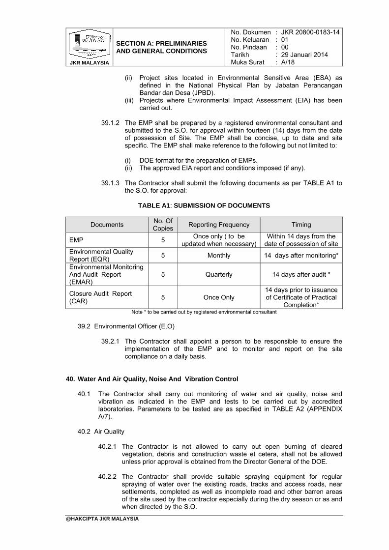
39.1.3 The Contractor shall submit the following documents as per TABLE A1 to
the S.O. for approval:
TABLE A1: SUBMISSION OF DOCUMENTS
Documents No. Of Copies
Reporting Frequency Timing
EMP 5 Once only ( to be
updated when necessary)Within 14 days from the
date of possession of site Environmental Quality Report (EQR)
5 Monthly 14 days after monitoring*
Environmental Monitoring And Audit Report (EMAR)
5 Quarterly 14 days after audit *
Closure Audit Report (CAR)
5 Once Only 14 days prior to issuance of Certificate of Practical
Completion* Note * to be carried out by registered environmental consultant
39.2 Environmental Officer (E.O)
39.2.1 The Contractor shall appoint a person to be responsible to ensure the
implementation of the EMP and to monitor and report on the site compliance on a daily basis.
40. Water And Air Quality, Noise And Vibration Control
40.1 The Contractor shall carry out monitoring of water and air quality, noise and vibration as indicated in the EMP and tests to be carried out by accredited laboratories. Parameters to be tested are as specified in TABLE A2 (APPENDIX A/7).
40.2 Air Quality
40.2.1 The Contractor is not allowed to carry out open burning of cleared
vegetation, debris and construction waste et cetera, shall not be allowed unless prior approval is obtained from the Director General of the DOE.
40.2.2 The Contractor shall provide suitable spraying equipment for regular spraying of water over the existing roads, tracks and access roads, near settlements, completed as well as incomplete road and other barren areas of the site used by the contractor especially during the dry season or as and when directed by the S.O.
JKR MALAYSIA
SECTION A: PRELIMINARIES AND GENERAL CONDITIONS
No. DokumenNo. KeluaranNo. PindaanTarikhMuka Surat
: : : : :
JKR 20800-0183-1401 00 29 Januari 2014 A/19
@HAKCIPTA JKR MALAYSIA
40.2.3 When the Contractor’s trucks or equipment utilizes public or private roadways, all dirt and materials shall be removed from the trucks/ equipment by hosing, lorry wash-trough, et cetera before leaving the site.
40.2.4 The Contractor shall provide for the prompt removal of all dirt and other materials spilled from his or his sub-contractor’s vehicles on public or private roadways.
40.2.5 For Contractor’s trucks carrying sand, aggregates, earth and other loose construction materials liable to spillage, tarpaulin must be used to cover such open trucks when passing through villages and settlements or on all roadways.
40.2.6 The Contractor shall also ensure dust control at quarry / batching plant (if
any) complies with environmental requirement as stipulated in the Environmental Quality (Clean Air) Regulations, 1978.
40.3 Vibration Control
40.3.1 The Contractor shall ensure that at any time, the vibration levels resulting
from his works at or across real property boundary should not exceed the Recommended Limit as Specified in TABLE A2 (APPENDIX A/7). No person unless duly authorized by law or carrying our legitimate duties shall use explosives or results in explosions which create a vibration disturbance across a real property boundary or on a public space or right of way.
40.3.2 The Contractor shall comply with the general recommendations set out in DOE Interim Planning Guidelines for Vibration Limits and Control in the Environment together with any specific requirements described in the Contract.
40.3.3 The Contractor shall indemnify and keep indemnified the Government, S.O.
and the S.O.’s Representatives against any liability for damages on account of vibration disturbance created while or in carrying out of the works and from and against all claims, demands, proceedings, damages, costs charges and expenses whatever in regard or in relation to such liability.
41. Nominated Sub-contractors
41.1 The Contractor shall allow in his tender price for attendance and facilities upon all Nominated Sub-contractors. Such attendance and facilities shall include the following: (i) Ascertaining from Nominated Sub-contractors all particulars relating to their
work in regard to sizes and positions in which chases, holes, mortices, et cetera are required to be formed or left.
(ii) Making good of walls, ceilings, floors, roofs, et cetera and finishes thereto
including touching up of all paintwork necessitated, damaged or disturbed by the Nominated Sub-contractor’s work.
(iii) Supplying all setting out information. (iv) Giving all necessary dimensions and taking responsibility for their accuracy. (v) Affording free and full use of standing scaffolding whilst it remains erected on
the Site.
JKR MALAYSIA
SECTION A: PRELIMINARIES AND GENERAL CONDITIONS
No. DokumenNo. KeluaranNo. PindaanTarikhMuka Surat
: : : : :
JKR 20800-0183-1401 00 29 Januari 2014 A/20
@HAKCIPTA JKR MALAYSIA
(vi) Affording free and full use of storage accommodation for materials, equipment and plant which are for incorporation into the Works and/or which require protection against weather and deterioration, messrooms, sanitary and welfare facilities.
(vii) Providing site space only for Nominated Sub-contractor’s temporary office,
workshops, workmen’s accommodation and storage of materials, tools, plant and equipment which are not for incorporation into the Works and not requiring protection against weather or deterioration.
(viii) Providing temporary water supply, electric power supply, artificial lighting and
paying all fees and charges for fuel, water and electricity consumed including for testing and commissioning of the whole Nominated Sub-contractor’s works.
(ix) Liaising with the relevant supply/service authorities for the expeditious
installation of the connections for permanent water and electricity supplies in the Works making available such supplies to the Nominated Sub-contractors; and paying all fees and charges for such installation, deposits for such supplies/services on behalf of the Government. All such payments made, shall be reimbursed to the Contractor on production of receipted bills.
(x) Providing competent personnel in compliance with the latest Electricity
Regulations to take responsibility for the operation of the electrical installation from the time the permanent electricity supply is made available until testing, commissioning and handing over of the Works.
(xi) Protecting, watching and taking full responsibility for all Nominated Sub-
contractor’s work and unfixed materials and goods intended for use thereon. (xii) Removing rubbish and debris off the Site and cleaning the Works internally and
externally.
41.2 It is deemed that the Nominated Sub-contractor shall include in the sub-contract Sum, inter alia, the costs in connection with the following:
(i) Unloading, getting in, storing and all handling and hoisting of these materials,
plant and tools into required positions. (ii) Providing, erecting, maintaining and removing of all his temporary office,
workshops and workmen’s accommodation including paying all assessment and other charges.
(iii) Connecting to temporary water and power supplies made available by the
Contractor for the execution of the Works, supplying and running distribution pipes, hoses, cables, leads, electrical gear, et cetera but excluding payment for water and electricity consumed.
(iv) Provision of fuel, gas, steam, oil lubricants, chemicals and everything else
necessary (other than water and electricity) for the test running and commissioning of the Sub-contract Works.
(v) Any scaffolding, staging, et cetera that are required for the Sub-contract Works
not covered by sub-section 41.1(v) above.
JKR MALAYSIA
SECTION A: PRELIMINARIES AND GENERAL CONDITIONS
No. DokumenNo. KeluaranNo. PindaanTarikhMuka Surat
: : : : :
JKR 20800-0183-1401 00 29 Januari 2014 A/21
@HAKCIPTA JKR MALAYSIA
42. Nominated Suppliers
The Contractor shall allow in his tender, price for attendance upon all Nominated Suppliers which is to include taking delivery, unloading, setting in, checking and accepting delivery, returning empties, handling, storing and hoisting of the materials/goods supplied by the Nominated Suppliers. Packing and carriage to Site shall be borne by the Nominated Supplier unless specifically stated to the contrary.
43. Coordination Of Mechanical And Electrical Services
43.1 General
This section shall describe the scope of works, qualifications, competency, roles and responsibilities of the Mechanical and Electrical (M & E) Services Coordination Team.
43.2 Scope Of Work 43.2.1 The Contractor shall be responsible for coordinating the implementation of
all M & E works and related activities within the project scope. For this purpose the Contractor shall appoint M & E Services Coordinators full time on site during the whole duration of the works. The appointment shall be approved by the S.O.
43.2.2 The Contractor shall ensure all M & E requirements are implemented in a timely manner and adequately integrated with all services involved such as architectural, structural and other related services.
43.2.3 The Contractor shall conduct regular coordination meetings among all
sub-contractors, nominated or otherwise, from related disciplines to evaluate and resolve all issues or problems regarding integration and coordination of all services.
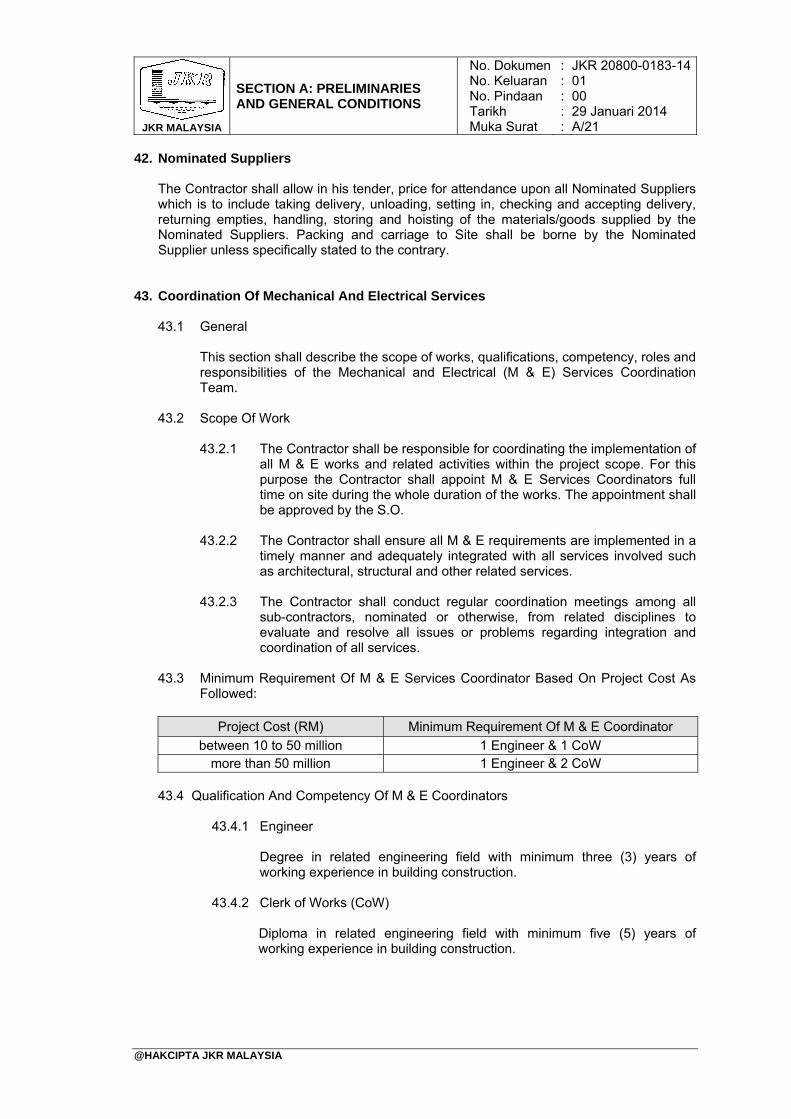
43.3 Minimum Requirement Of M & E Services Coordinator Based On Project Cost As
Followed:
Project Cost (RM) Minimum Requirement Of M & E Coordinator
between 10 to 50 million 1 Engineer & 1 CoW more than 50 million 1 Engineer & 2 CoW
43.4 Qualification And Competency Of M & E Coordinators
43.4.1 Engineer Degree in related engineering field with minimum three (3) years of working experience in building construction.
43.4.2 Clerk of Works (CoW)
Diploma in related engineering field with minimum five (5) years of working experience in building construction.
JKR MALAYSIA
SECTION A: PRELIMINARIES AND GENERAL CONDITIONS
No. DokumenNo. KeluaranNo. PindaanTarikhMuka Surat
: : : : :
JKR 20800-0183-1401 00 29 Januari 2014 A/22
@HAKCIPTA JKR MALAYSIA
43.5 Responsibilities Of M & E Services Coordinator
43.5.1 The M & E Services Coordinator shall be responsible, on behalf of the Contractor for :
(i) Guiding the overall M & E works and implementation of related
activities within the project scope and providing timely and relevant information.
(ii) Ensuring that all layout, schematic, detail and Builder’s Work in Connection (BWIC) drawings (for architectural, structural, mechanical and electrical works) are received from the S.O.
(iii) Supervising all the installation and construction works to ensure the works are sufficiently coordinated.
(iv) Identifying and resolving issues or problems related to integration and coordination of services by producing coordinated services drawing, new method of installation and et cetera.
44. Keeping The Site Tidy 44.1 The Contractor shall make every effort to keep the Site in a reasonably clean and
tidy condition for the duration of the Works. He shall, in addition, from time to time and on the completion of any area of the Works or where directed by the S.O., remove rubbish, surplus materials, or any other construction debris from such areas as may be attributable to his work under this Contract and generally maintain the Site in a satisfactory condition, to the approval of the S.O.
44.2 The Contractor shall gather up and clear away all rubbish as it accumulates during the progress of the Works at least twice each week at times approved by the S.O. The services shall be continued until the completion of the Works. Garbage or construction waste shall be disposed in a locally available landfill or hauled to disposal sites approved by the S.O.
45. As-built Drawings 45.1 The Contractor shall provide and deliver to the S.O. approved As-built drawings
after completion of each section of the Works in the form of : (i) Four (4) sets of As-built drawings as actually constructed pertaining to the
Works including all services and facilities systems and all supporting documents such as Operation and Maintenance Manual, Testing and Commissioning Certificates. All As-built drawings for building works shall show the immovable asset registration coding in accordance with the Government’s “Immovable Asset Code System” (Sistem Kod Aset Tak Alih - SKATA).
(ii) Four (4) sets of Digital Copies in AutoCAD (.dwg) format to be stored in compact discs or removable storage.
(iii) Four (4) sets of Digital Copies in Acrobat (.pdf) format to be stored in compact discs or removable storage.
45.2 The As-built drawings supplied shall be comprehensive and to the satisfaction of the S.O. as to allow for a complete understanding of the Works as they were actually built incorporating all Works arising from variations, expenditure of Provisional Sums and Prime Cost Sums.
45.3 The As-built drawings shall be endorsed by a Professional Architect/Engineer/Surveyor registered with the respective Professional Boards in Malaysia.
JKR MALAYSIA
SECTION A: PRELIMINARIES AND GENERAL CONDITIONS
No. DokumenNo. KeluaranNo. PindaanTarikhMuka Surat
: : : : :
JKR 20800-0183-1401 00 29 Januari 2014 A/23
@HAKCIPTA JKR MALAYSIA
46. Clearing, Cleaning And Making Good On Completion
46.1 The Contractor shall ensure the existing roadside drains bounding the Site are clear of any building debris, earth, et cetera, at all times before handing over of the Works to the S.O. upon completion.
46.2 Upon completion of the Works, the Contractor shall remove and clear away from Site all temporary buildings, temporary works, temporary installation and equipment, and ensure the Site is in a clean and tidy condition.
46.3 Before handing over of the Works, the Contractor shall scrub all floors, pavings, staircases et cetera and clean out all gutters, gulleys, manholes, sumps and drains. The Contractor shall also clean all glass panes and leave every part of the completed Works included in this Contract in a clean, sound and tidy condition to the approval of the S.O.
JKR MALAYSIA
SECTION A: PRELIMINARIES AND GENERAL CONDITIONS
No. DokumenNo. KeluaranNo. PindaanTarikhMuka Surat
: : : : :
JKR 20800-0183-1401 00 29 Januari 2014 A/24
@HAKCIPTA JKR MALAYSIA
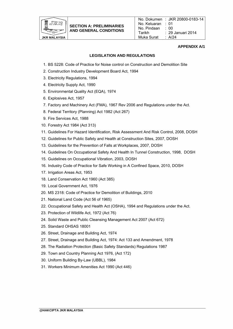
APPENDIX A/1
LEGISLATION AND REGULATIONS
1. BS 5228: Code of Practice for Noise control on Construction and Demolition Site
2. Construction Industry Development Board Act, 1994
3. Electricity Regulations, 1994
4. Electricity Supply Act, 1990
5. Environmental Quality Act (EQA), 1974
6. Explosives Act, 1957
7. Factory and Machinery Act (FMA), 1967 Rev 2006 and Regulations under the Act.
8. Federal Territory (Planning) Act 1982 (Act 267)
9. Fire Services Act, 1988
10. Forestry Act 1984 (Act 313)
11. Guidelines For Hazard Identification, Risk Assessment And Risk Control, 2008, DOSH
12. Guidelines for Public Safety and Health at Construction Sites, 2007, DOSH
13. Guidelines for the Prevention of Falls at Workplaces, 2007, DOSH
14. Guidelines On Occupational Safety And Health In Tunnel Construction, 1998, DOSH
15. Guidelines on Occupational Vibration, 2003, DOSH
16. Industry Code of Practice for Safe Working in A Confined Space, 2010, DOSH
17. Irrigation Areas Act, 1953
18. Land Conservation Act 1960 (Act 385)
19. Local Government Act, 1976
20. MS 2318: Code of Practice for Demolition of Buildings, 2010
21. National Land Code (Act 56 of 1965)
22. Occupational Safety and Health Act (OSHA), 1994 and Regulations under the Act.
23. Protection of Wildlife Act, 1972 (Act 76)
24. Solid Waste and Public Cleansing Management Act 2007 (Act 672)
25. Standard OHSAS 18001
26. Street, Drainage and Building Act, 1974
27. Street, Drainage and Building Act, 1974: Act 133 and Amendment, 1978
28. The Radiation Protection (Basic Safety Standards) Regulations 1987
29. Town and Country Planning Act 1976, (Act 172)
30. Uniform Building By-Law (UBBL), 1984
31. Workers Minimum Amenities Act 1990 (Act 446)

JKR MALAYSIA
SECTION A: PRELIMINARIES AND GENERAL CONDITIONS
No. DokumenNo. KeluaranNo. PindaanTarikhMuka Surat
: : : : :
JKR 20800-0183-1401 00 29 Januari 2014 A/25
@HAKCIPTA JKR MALAYSIA
APPENDIX A/2
LIST OF S.O.’S FACILITIES AND EQUIPMENT

JKR MALAYSIA
SECTION A: PRELIMINARIES AND GENERAL CONDITIONS
No. DokumenNo. KeluaranNo. PindaanTarikhMuka Surat
: : : : :
JKR 20800-0183-1401 00 29 Januari 2014 A/26
@HAKCIPTA JKR MALAYSIA
APPENDIX A/3
LIST OF S.O.’S TRANSPORT SERVICES

JKR MALAYSIA
SECTION A: PRELIMINARIES AND GENERAL CONDITIONS
No. DokumenNo. KeluaranNo. PindaanTarikhMuka Surat
: : : : :
JKR 20800-0183-1401 00 29 Januari 2014 A/27
@HAKCIPTA JKR MALAYSIA
APPENDIX A/4
LIST OF LABORATORY EQUIPMENT

JKR MALAYSIA
SECTION A: PRELIMINARIES AND GENERAL CONDITIONS
No. DokumenNo. KeluaranNo. PindaanTarikhMuka Surat
: : : : :
JKR 20800-0183-1401 00 29 Januari 2014 A/28
@HAKCIPTA JKR MALAYSIA
APPENDIX A/5
REQUIREMENTS OF SAFETY AND HEALTH PLAN (S-PLAN)
1. Project Introduction and Scope of Works associated with OSH; 2. Contractor’s Authorised and Updated OSH Policy; 3. Contractor’s Organisation Chart and Safety And Health Committee (SHC) Chart which
shall describing the staff involved including list of duties and responsibilities; 4. Communication, Consultation and Involvement of each member of the Contractor’s
project team as shown in the Item (c), including their relationship, interfacings and cooperation of workmen for successful implementation of the project. The planning shall taking account control of any OSH related complaints, advice, OSH programmes and awareness, SHC meeting’s schedule, and solving OSH related issues;
5. Contractor’s Authorised Updated Compliance List on OSH Legislation and Other Related Requirements;
6. List of Prohibited foods and drinks including drugs and medicines; 7. List of Personal Protective Equipment at Works; 8. Schedule of OSH Trainings and Programmes to all workmen including sub-Contractor; 9. Emergency Response Plan;
10. Safe Work System on Temporary Electricity Installation Works; 11. Safe Operational Procedures; 12. Format of Incident investigation report; 13. Format of Daily Reporting on Incident Statistic; 14. Chemical Safety Data Sheets or Material Safety Data Sheets; 15. Health Precaution on workmen: Medical Report (Health Surveillance), noise
prevention; 16. Sanitation for workmen; 17. Safety Signage and Traffic Control; 18. Hazard Identification, Risk Assessment and Risk Control (HIRARC);
JKR MALAYSIA
SECTION A: PRELIMINARIES AND GENERAL CONDITIONS
No. DokumenNo. KeluaranNo. PindaanTarikhMuka Surat
: : : : :
JKR 20800-0183-1401 00 29 Januari 2014 A/29
@HAKCIPTA JKR MALAYSIA
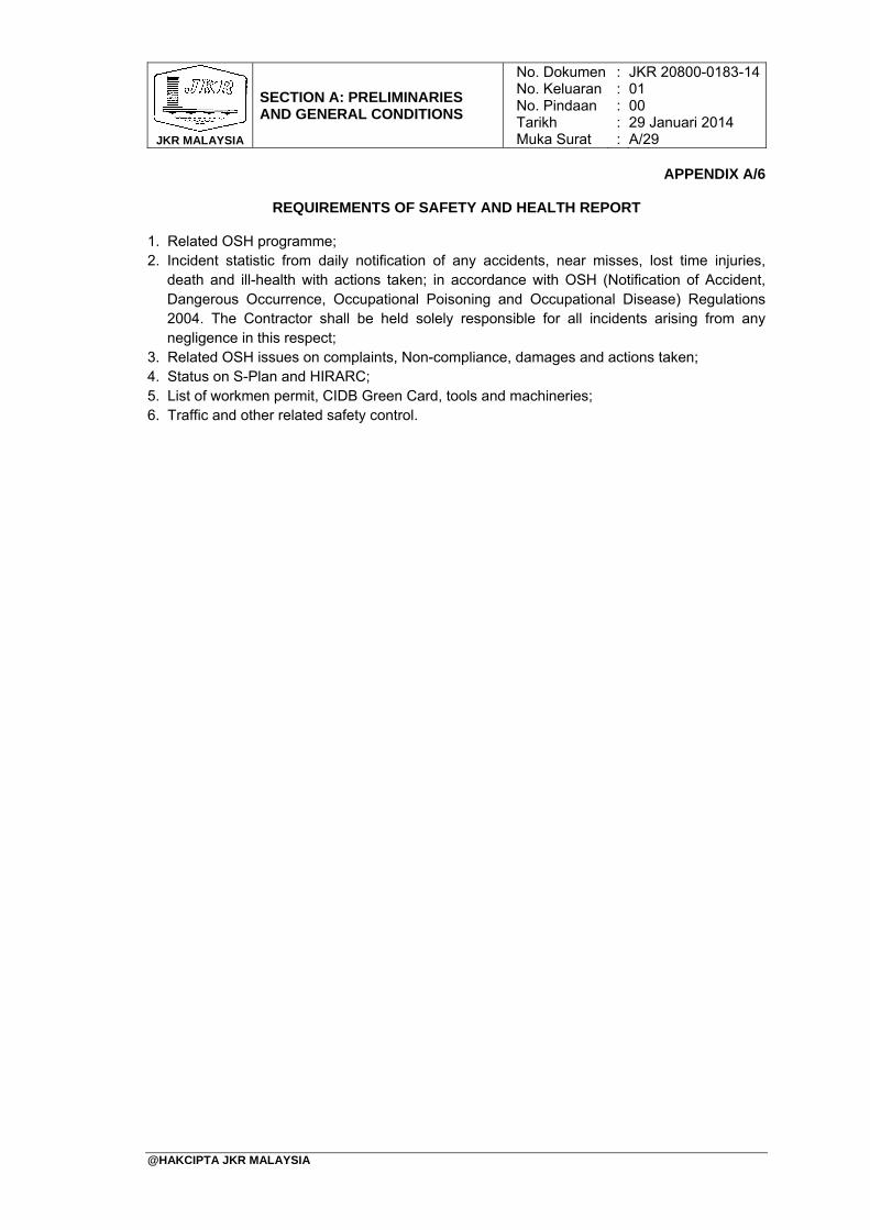
APPENDIX A/6
REQUIREMENTS OF SAFETY AND HEALTH REPORT
1. Related OSH programme; 2. Incident statistic from daily notification of any accidents, near misses, lost time injuries,
death and ill-health with actions taken; in accordance with OSH (Notification of Accident, Dangerous Occurrence, Occupational Poisoning and Occupational Disease) Regulations 2004. The Contractor shall be held solely responsible for all incidents arising from any negligence in this respect;
3. Related OSH issues on complaints, Non-compliance, damages and actions taken; 4. Status on S-Plan and HIRARC; 5. List of workmen permit, CIDB Green Card, tools and machineries; 6. Traffic and other related safety control.
JKR MALAYSIA
SECTION A: PRELIMINARIES AND GENERAL CONDITIONS
No. DokumenNo. KeluaranNo. PindaanTarikhMuka Surat
: : : : :
JKR 20800-0183-1401 00 29 Januari 2014 A/30
@HAKCIPTA JKR MALAYSIA
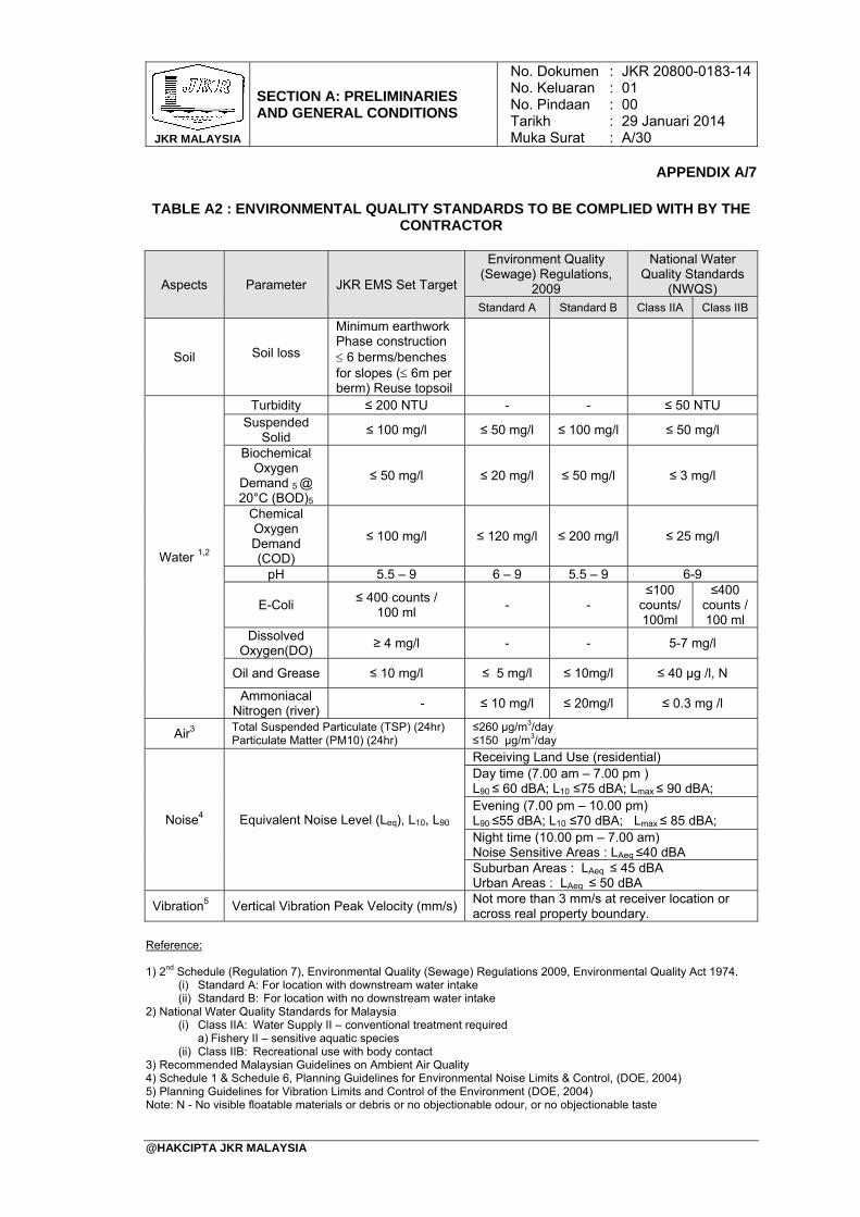
APPENDIX A/7
TABLE A2 : ENVIRONMENTAL QUALITY STANDARDS TO BE COMPLIED WITH BY THE CONTRACTOR
Reference: 1) 2nd Schedule (Regulation 7), Environmental Quality (Sewage) Regulations 2009, Environmental Quality Act 1974.
(i) Standard A: For location with downstream water intake (ii) Standard B: For location with no downstream water intake
2) National Water Quality Standards for Malaysia (i) Class IIA: Water Supply II – conventional treatment required
a) Fishery II – sensitive aquatic species (ii) Class IIB: Recreational use with body contact
3) Recommended Malaysian Guidelines on Ambient Air Quality 4) Schedule 1 & Schedule 6, Planning Guidelines for Environmental Noise Limits & Control, (DOE, 2004) 5) Planning Guidelines for Vibration Limits and Control of the Environment (DOE, 2004) Note: N - No visible floatable materials or debris or no objectionable odour, or no objectionable taste
Aspects Parameter JKR EMS Set Target
Environment Quality (Sewage) Regulations,
2009
National Water Quality Standards
(NWQS) Standard A Standard B Class IIA Class IIB
Soil Soil loss
Minimum earthwork Phase construction 6 berms/benches for slopes ( 6m per berm) Reuse topsoil
Water 1,2
Turbidity ≤ 200 NTU - - ≤ 50 NTU Suspended
Solid ≤ 100 mg/l ≤ 50 mg/l ≤ 100 mg/l ≤ 50 mg/l
Biochemical Oxygen
Demand 5 @ 20°C (BOD)5
≤ 50 mg/l ≤ 20 mg/l ≤ 50 mg/l ≤ 3 mg/l
Chemical Oxygen Demand (COD)
≤ 100 mg/l ≤ 120 mg/l ≤ 200 mg/l ≤ 25 mg/l
pH 5.5 – 9 6 – 9 5.5 – 9 6-9
E-Coli ≤ 400 counts /
100 ml - -
≤100 counts/ 100ml
≤400 counts / 100 ml
Dissolved Oxygen(DO)
≥ 4 mg/l - - 5-7 mg/l
Oil and Grease ≤ 10 mg/l ≤ 5 mg/l ≤ 10mg/l ≤ 40 µg /l, N
Ammoniacal Nitrogen (river)
- ≤ 10 mg/l ≤ 20mg/l ≤ 0.3 mg /l
Air3 Total Suspended Particulate (TSP) (24hr) Particulate Matter (PM10) (24hr)
≤260 µg/m3/day ≤150 µg/m3/day
Noise4 Equivalent Noise Level (Leq), L10, L90
Receiving Land Use (residential) Day time (7.00 am – 7.00 pm ) L90 ≤ 60 dBA; L10 ≤75 dBA; Lmax ≤ 90 dBA; Evening (7.00 pm – 10.00 pm) L90 ≤55 dBA; L10 ≤70 dBA; Lmax ≤ 85 dBA; Night time (10.00 pm – 7.00 am) Noise Sensitive Areas : LAeq ≤40 dBA Suburban Areas : LAeq ≤ 45 dBA Urban Areas : LAeq ≤ 50 dBA
Vibration5 Vertical Vibration Peak Velocity (mm/s) Not more than 3 mm/s at receiver location or across real property boundary.
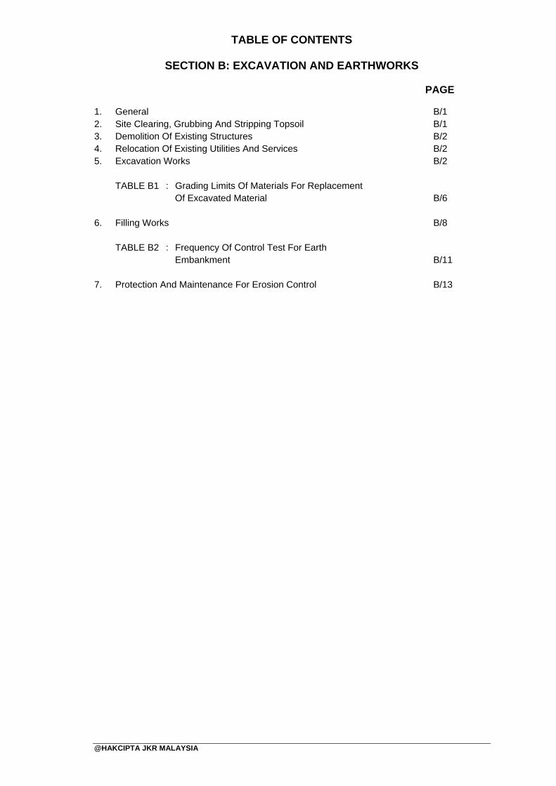
TABLE OF CONTENTS
SECTION B: EXCAVATION AND EARTHWORKS
PAGE
@HAKCIPTA JKR MALAYSIA
1. General 2. Site Clearing, Grubbing And Stripping Topsoil 3. Demolition Of Existing Structures 4. Relocation Of Existing Utilities And Services 5. Excavation Works
TABLE B1 : Grading Limits Of Materials For Replacement
Of Excavated Material
6. Filling Works TABLE B2 : Frequency Of Control Test For Earth Embankment
7. Protection And Maintenance For Erosion Control
B/1 B/1 B/2 B/2 B/2 B/6 B/8 B/11 B/13

JKR MALAYSIA
SECTION B : EXCAVATION AND EARTHWORKS
No. DokumenNo. KeluaranNo. PindaanTarikhMuka Surat
: : : : :
JKR 20800-0183-1401 00 29 Januari 2014 B/1
@HAKCIPTA JKR MALAYSIA
1. General
1.1 This work shall consist of all the required excavation within the limits of the Works. It shall include the removal and proper utilization and hauling, or disposal of all excavated materials, and constructing, shaping and finishing of all earthworks over the entire extent of the Works, in conformity with the Drawings and these Specifications.
1.2 The excavation and earthworks shall be executed in such a manner and order as approved by the S.O. The Contractor shall be responsible for compliance with by-laws and regulations relating to earthworks.
1.3 Excavation in rock and/or hard material shall respectively be measured and paid for as extra over to excavation and earthworks in accordance with the Provisional B.Q. The Contractor shall give reasonable notice to the S.O. to examine, classify the excavation and to take measurement prior to breaking up.
1.4 For contract based on Specifications and Drawings, unless otherwise provided in the Contract, for the purpose of pricing the excavation and earthworks, the whole excavation shall be assumed to be without rock and/or hard material as defined hereunder.
1.5 For contract based on Quantities, the pricing shall be in accordance with the B.Q.
1.6 Computation of volume of rock excavation for payment shall be based on nett volume excavated as shown on the Drawings.
1.7 The Contractor shall comply with all statutory requirements and regulations such as payment of royalties and environmental protection for removal of unsuitable material and borrow materials.
2. Site Clearing, Grubbing And Stripping Topsoil
2.1 This work shall consist of clearing, grubbing and stripping topsoil in the areas within the limits of Works designated hereunder and/or shown on the Drawings and/or directed by the S.O., and of clearing only in other areas designated hereunder and/or shown on the Drawings and/or directed by the S.O., all as specified herein and as required by the S.O. The work shall also include the demolition and disposal of structures in the said areas, except where otherwise provided for in the Contract, as specified herein and as required by the S.O.
2.1.1 Site clearing
Clearing shall consist of cutting and/or taking down, removal and disposal of everything above ground level, including objects such as walls, fences, drains and other obstructions, except such trees, vegetation, structures or parts of structures and other things which are designated in the Contract to remain, to be protect as satisfied under SECTION R : LANDSCAPING AND TURFING WORKS. The material to be cleared shall include but not necessarily be limited to trees, stumps (parts above ground), logs, brushwood, undergrowth, long grasses, crops, loose vegetable matter and structures (except those structures whose removal or clearance is otherwise provided for in the Contract). Clearing shall also include levelling of obsolete dikes, terraces, ditches, et cetera, unless otherwise directed by the S.O.
JKR MALAYSIA
SECTION B : EXCAVATION AND EARTHWORKS
No. DokumenNo. KeluaranNo. PindaanTarikhMuka Surat
: : : : :
JKR 20800-0183-1401 00 29 Januari 2014 B/2
@HAKCIPTA JKR MALAYSIA
2.1.2 Grubbing
Grubbing shall consist of removal and disposal of surface vegetation, bases of stumps, roots, underground parts of structures, and other obstructions to a depth of at least 0.50 m below ground level, with the agreement of the S.O.
2.1.3 Stripping topsoil
Stripping topsoil shall consist of the removal of topsoil to an average depth of at least 100 mm below ground level, and its stockpiling for use in the Works, and/or its disposal, as directed by the S.O.
2.1.4 Disposal
All materials resulting from site clearing, grubbing and stripping topsoil shall be removed and disposed of as approved by the S.O. in accordance with Environmental Quality Act 1974(Act 127) and Solid Waste and Public Cleansing Management Act 2007 (Act 672).
3. Demolition Of Existing Structures
3.1 Major structures are those which cannot practicably be cleared by bulldozer and/or hydraulic excavator, whose demolition requires pneumatic tools, explosives and/or other specialized equipment. A brief description of each major structure (if any) and depth to which extent it shall be demolished is given in the B.Q.
3.2 All fences, buildings, structures, and encumbrances of any character within the limits of the limits of the Works, except those to be removed by others or designated to remain, shall be demolished and removed by the Contractor.
3.3 Materials designated in the Contract or directed by the S.O. to be salvaged, shall be
carefully removed and stored, and shall be the property of the Government. 4. Relocation Of Existing Utilities And Services
4.1 The Contractor's attention is specially drawn to his responsibilities under the Clause
headed ‘Damage to Property' of the Condition of Contract.
4.2 Before commencing on any excavation, the Contractor or his representative shall accompany the S.O. on a site inspection to identify the presence of underground cables, water or other service pipes at or in the vicinity of such excavation. Thereafter, the Contractor shall carry out the excavation work in a manner and sequence as approved by the S.O.
4.3 If during excavation, the Contractor's workmen uncover any cables, water or other
service pipes, work shall be stopped immediately and shall not be again started until the matter has been reported to the S.O. who will notify the appropriate local authority, and subsequently issue whatever directions he deemed appropriate.
5. Excavation Works
5.1 General Requirements
5.1.1 The work shall include the excavation of all types of material, backfilling, compaction, forming embankments and slopes, et cetera, as is necessary
JKR MALAYSIA
SECTION B : EXCAVATION AND EARTHWORKS
No. DokumenNo. KeluaranNo. PindaanTarikhMuka Surat
: : : : :
JKR 20800-0183-1401 00 29 Januari 2014 B/3
@HAKCIPTA JKR MALAYSIA
for the completion of the works up to the formation levels, in accordance with the lines, grades, dimensions, shapes and typical cross-sections shown on the Drawings and to the approval of the S.O.
5.1.2 The Contractor shall provide where necessary temporary water courses,
ditches, drains, pumping or other means of maintaining the earthworks free from water. Such provision shall include carrying out the work of forming the cuttings and embankments in such a manner that their surfaces have at all times a sufficient gradient to enable them to shed water and prevent water ponding.
5.1.3 In pumping water out from excavation and in the lowering of water table
the Contractor shall pay due regard to the stability and settlement of all structures.
5.1.4 Adequate means for trapping silt shall be provided on all temporary drainage systems. Similar arrangements shall be made for all earthworks including excavation whether for pile trenches, foundations or cuttings.
5.1.5 Should the surface of completed areas be damaged by erosion or by any other causes, the Contractor shall at his own cost make good such areas to the approval of the S.O.
5.1.6 The Contractor shall exercise care in preventing wastage of suitable material needed for embankment or fill construction.
5.2 Definitions
5.2.1 Formation level
Formation level means the final earthwork level after cutting or filling.
5.2.2 Common excavation Common excavation shall mean excavation in any materials which are not rock or hard materials as defined in sub-sections 5.2.5 and 5.2.6.
5.2.3 Unsuitable materials 5.2.3.1 Unsuitable materials shall include:
(i) Running silt, peat, logs, stumps, roots, grass and other
vegetable matter, perishable or toxic material, slurry or mud; or
(ii) Organic clay and organic silt; or (iii) Any material
a) which is susceptible to spontaneous combustion; or b) which is clay having a liquid limit exceeding 80%
and/or a plasticity index exceeding 55%; or c) which has a loss of weight greater than 2.5% on
ignition.
5.2.3.2 Materials that are soft or unstable merely because they are too wet or too dry for effective compaction shall not to be classified as unsuitable, unless otherwise classified by the S.O.
JKR MALAYSIA
SECTION B : EXCAVATION AND EARTHWORKS
No. DokumenNo. KeluaranNo. PindaanTarikhMuka Surat
: : : : :
JKR 20800-0183-1401 00 29 Januari 2014 B/4
@HAKCIPTA JKR MALAYSIA
5.2.4 Suitable materials
5.2.4.1 Suitable materials shall mean those materials other than the unsuitable materials defined in sub-section 5.2.3.
5.2.4.2 General fill shall generally comprise of suitable materials made up of either cohesive soil or cohesion less soil or mixture of both. The classification of cohesive and cohesion less soil shall be based on Soil Classification System set out in the latest MS 1056: Site Investigation.
5.2.4.3 Special fill shall comprise of material, which would otherwise be
classified as general fill but which contains durable well-graded natural sand and gravel or crushed rock, other than argillaceous rock, or durable clean crushed demolition rubble of similar particle size and free from any contaminants.
5.2.5 Hard material
5.2.5.1 This shall mean any hard material which can be excavated using
an excavator with minimum weight of 44 tonnes and nett horsepower rating of 321 brake horsepower with production rate not exceeding 50 m3 / hour. The excavator unit is to be in good condition and operated by experienced personnel.
5.2.5.2 Hard material shall exclude individual masses less than 0.5 m3.
5.2.5.3 Trial excavation shall be carried out using the above equipment to determine hard material. The trial excavation shall be carried out on a flat platform in order to develop the rated horsepower at maximum efficiency.
5.2.6 Rock
5.2.6.1 Rock shall mean material found in ledges or masses which can
be excavated using the following equipment with production rate not exceeding 20 m3 / hour: (i) Track-type tractor (dozer)
Equipment with minimum weight of 37 tonnes and nett horsepower rating of 305 brake horsepower or more (D8R or equivalent). The tractor unit is to be in good condition and operated by experienced personnel skilled in the use of ripping equipment; and
(ii) Ripping unit
The ripper to be attached to the above mentioned tractor shall have a minimum penetration force of 120 kN. The ripper shall have a single shank in good working condition with sharpened cutting point.
5.2.6.2 Trial excavation shall be carried out using the above equipment to determine rock.
5.2.6.3 Boulders or detached pieces shall only be regarded as rock if they individually exceed 0.5 m3. For determination of the volume of individual boulder, diameters of the boulder in three (3) orthogonal directions shall be taken. The average of the three (3)
JKR MALAYSIA
SECTION B : EXCAVATION AND EARTHWORKS
No. DokumenNo. KeluaranNo. PindaanTarikhMuka Surat
: : : : :
JKR 20800-0183-1401 00 29 Januari 2014 B/5
@HAKCIPTA JKR MALAYSIA
diameters shall be used to calculate the volume of boulder. Records of measurements and photographs shall be taken and kept to support the calculation of the volume of boulder.
5.3 Dimensional Tolerances
Slopes in cutting shall be trimmed mechanically to neat and even surfaces which shall have gradients not steeper than that shown on the Drawings. Widths of excavations shall not exceed the dimensions shown on the Drawings by more than 300 mm with encumbrance free to complete the Work, unless otherwise approved by the S.O.
5.4 Separation And Stockpiling Of Suitable Material
Where excavation reveals a combination of suitable and unsuitable materials, the Contractor shall, wherever the S.O. considers it practicable, carry out the excavation in such a manner that the suitable materials are excavated separately for use in the Works without contamination by the unsuitable materials.
5.5 Removal Of Excavated Material From Site
5.5.1 Trial pit shall be carried out prior to removal of material to be excavated to confirm water table and depth of excavation.
5.5.2 No excavated material shall be removed from the Site except on the
direction or with the approval of the S.O. Should the Contractor be permitted to remove suitable materials from the Site to suit his operational procedure, then he shall make good any consequent deficit of fill material arising there from, at his own expense. Unless designated dump sites have been shown on the Drawings, the Contractor shall dispose of surplus suitable material at his own dump areas outside the Site as approved by the S.O.
5.6 Removal Of Unsuitable Material
5.6.1 Trial pit shall be carried out prior to removal of material to be excavated to
confirm water table and depth of excavation.
5.6.2 Unsuitable material shall be excavated to such depth and over such area as shown on the Drawings and/or directed by the S.O. and be transported and disposed off in an approved manner. Unless approval of the S.O. to dump and spread the unsuitable material within the Site is obtained, the Contractor shall be responsible for providing his own dump site for such unsuitable material.
5.7 Replacement Of Excavated Material Under Standing Water
Where it is decided by the S.O. that replacement of excavated material shall be done under standing water, voids created due to removal of excavated material shall be backfilled with hard clean crushed rock, natural gravel or sand having grading within the respective limits specified in TABLE B1.
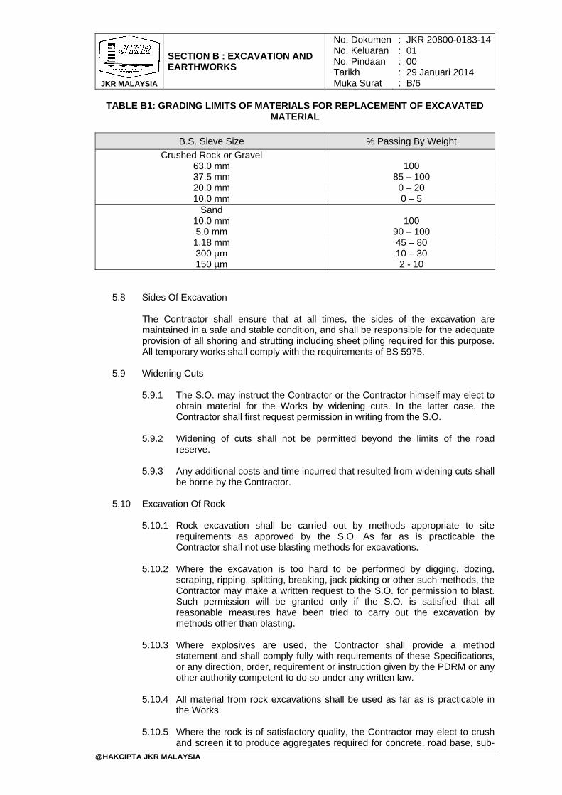
JKR MALAYSIA
SECTION B : EXCAVATION AND EARTHWORKS
No. DokumenNo. KeluaranNo. PindaanTarikhMuka Surat
: : : : :
JKR 20800-0183-1401 00 29 Januari 2014 B/6
@HAKCIPTA JKR MALAYSIA
TABLE B1: GRADING LIMITS OF MATERIALS FOR REPLACEMENT OF EXCAVATED MATERIAL
B.S. Sieve Size % Passing By Weight
Crushed Rock or Gravel 63.0 mm 100 37.5 mm 85 – 100 20.0 mm 0 – 20 10.0 mm 0 – 5
Sand 10.0 mm 100 5.0 mm 90 – 100 1.18 mm 45 – 80 300 µm 10 – 30 150 µm 2 - 10
5.8 Sides Of Excavation
The Contractor shall ensure that at all times, the sides of the excavation are maintained in a safe and stable condition, and shall be responsible for the adequate provision of all shoring and strutting including sheet piling required for this purpose. All temporary works shall comply with the requirements of BS 5975.
5.9 Widening Cuts
5.9.1 The S.O. may instruct the Contractor or the Contractor himself may elect to
obtain material for the Works by widening cuts. In the latter case, the Contractor shall first request permission in writing from the S.O.
5.9.2 Widening of cuts shall not be permitted beyond the limits of the road reserve.
5.9.3 Any additional costs and time incurred that resulted from widening cuts shall be borne by the Contractor.
5.10 Excavation Of Rock
5.10.1 Rock excavation shall be carried out by methods appropriate to site
requirements as approved by the S.O. As far as is practicable the Contractor shall not use blasting methods for excavations.
5.10.2 Where the excavation is too hard to be performed by digging, dozing, scraping, ripping, splitting, breaking, jack picking or other such methods, the Contractor may make a written request to the S.O. for permission to blast. Such permission will be granted only if the S.O. is satisfied that all reasonable measures have been tried to carry out the excavation by methods other than blasting.
5.10.3 Where explosives are used, the Contractor shall provide a method statement and shall comply fully with requirements of these Specifications, or any direction, order, requirement or instruction given by the PDRM or any other authority competent to do so under any written law.
5.10.4 All material from rock excavations shall be used as far as is practicable in
the Works.
5.10.5 Where the rock is of satisfactory quality, the Contractor may elect to crush and screen it to produce aggregates required for concrete, road base, sub-
JKR MALAYSIA
SECTION B : EXCAVATION AND EARTHWORKS
No. DokumenNo. KeluaranNo. PindaanTarikhMuka Surat
: : : : :
JKR 20800-0183-1401 00 29 Januari 2014 B/7
@HAKCIPTA JKR MALAYSIA
base, or other purposes with the prior approval of the S.O. Excavated rock needed for earthwork construction which the Contractor elects so to use for producing aggregate materials shall be replaced at the Contractor's own expense by borrow materials of satisfactory quality from alternative locations approved by the S.O.
5.10.6 Otherwise, excavated rock shall be used in the construction of embankment and fill, to the fullest practical extent, in either of the two (2) following ways:
(i) Excavated rock shall be broken down to a maximum particle size of
300 mm and used as rock fill as described in sub-section 5.2.6;
(ii) Excavated rock shall be broken down to a maximum particle size of 150 mm, blended with suitable earth fill material in a proportion not exceeding 1 rock to 1 earth, and used as common fill.
5.10.7 The Contractor may only waste excavated rock with the approval of the S.O. Excavated rock needed for earthwork construction which the Contractor elects to waste shall be replaced at the Contractor's own expense by borrow materials of satisfactory quality from alternative locations approved by the S.O.
5.11 Storage And Handling Of Explosives
Proper buildings or magazines, with separate compartments for detonators, in suitable positions for the storage of explosives in manner and quantities to be approved shall be provided in compliance with all authorities’ requirements. The prevention of any unauthorised issue or improper use of any explosive brought on the Works shall be the responsibility of the Contractor and only experienced and qualified personnel shall be employed to handle explosives for the purpose of the Works.
5.12 Blasting
5.12.1 Explosives shall be used in the quantities and manner recommended by the manufacturers and blasting specialist. Blasting shall be restricted to such periods as the S.O. may prescribe and to comply with all authorities requirement. If, in the opinion of the S.O., blasting would be dangerous to persons or properties or to any finished work, or is being carried on in a reckless manner, he may prohibit it, and order the rock to be excavated by other means. The use of explosives in large blasts, that is exceeding 9 kg of explosive, as in seams, drifts, shafts, pits, or large holes, is prohibited unless authorised in writing by the S.O. Such authorisation shall not in any way relieve the Contractor of his liabilities under the Conditions of Contract.
5.12.2 All necessary precautions shall be taken to preserve the materials below and beyond the lines of all excavations in the soundest possible condition. Delayed blasting to reduce shock waves shall be used to avoid damage to concrete and other works already completed. As the excavation approaches its final lines, blasting with pre-splitting technique of approved drill hole spacing shall be carried out to reduce blast damage and create reasonably even finished surface by means of parallel drill holes perpendicular to the toe of the excavation and parallel to the finally required face.
5.13 Safety Measures
5.13.1 When blasting is carried out close to properties or roads, safety rules
complying to authorities’ requirements shall be strictly adhered to. Where necessary or as directed by the S.O., heavy mesh blasting mats shall be used to ensure that no damage is caused to persons or properties on or off
JKR MALAYSIA
SECTION B : EXCAVATION AND EARTHWORKS
No. DokumenNo. KeluaranNo. PindaanTarikhMuka Surat
: : : : :
JKR 20800-0183-1401 00 29 Januari 2014 B/8
@HAKCIPTA JKR MALAYSIA
Site. Special care shall be taken in wet ground to ensure that individual explosions are reduced to such size as to preclude damage to any buildings or structures. Plaster shooting will not be permitted within 400 m of any building or structure. If traffic on any road or railway has to be interrupted for blasting operations, the Contractor shall obtain approval of his schedule for such interruption from the appropriate authorities and shall prove to the S.O. that he has obtained it, prior to the interruption.
5.13.2 When blasting is carried out with close proximity to sensitive structures and environmental sensitive areas, thresholds and criteria of vibration impact shall be established for monitoring purpose.
5.14 Insecure Material
The cut slopes shall be cleared of all rock fragments which move when pried with a crow-bar. The Contractor shall excavate any insecure material to an approved depth and build up the resulting spaces with Grade 15P/20 concrete or masonry using rock similar to the adjoining natural rock so as to ensure a solid face.
6. Filling Works
6.1 Material
6.1.1 Fill materials to form formation level shall be of suitable material obtained from excavation in cuttings. Where the quantity of such materials is inadequate, the Contractor shall obtain suitable materials from the designated borrow pits or from his own borrow pits which have been approved by the S.O.
6.1.2 The fill material shall be free from roots, grass, other vegetable material, clay lump or material of particles size larger than 150 mm.
6.1.3 Sand shall not be used as fill materials at outer edges of the embankment.
6.2 Borrow Pits
6.2.1 The Contractor shall be responsible for locating borrow pits. Designated
borrow pits shown on the Drawings only indicate to the Contractor potential areas for borrow. Whether the Contractor obtains materials from the designated or his own borrow pit, it shall be his responsibility to ascertain the suitability of the pit with respect to the quantity and quality of the materials, which shall be subjected to the approval of the S.O.
6.2.2 The Contractor shall keep the borrow pits free from water ponding and the excavation neat and tidy. The contractor shall make sure the side-wall of the borrow pits is stable, protect the slope surface by turfing and shall carry out other necessary erosion and environmental protection measures following the agreed method statement or as instructed by the S.O.
6.2.3 The following tests should be carried out for each 1,500 m3 of material to be
placed or more frequent tests as required by the S.O. : (i) Atterberg limits (ii) Gradation analysis (iii) M.S 1056 Compaction Test (2.5 kg rammer method)
JKR MALAYSIA
SECTION B : EXCAVATION AND EARTHWORKS
No. DokumenNo. KeluaranNo. PindaanTarikhMuka Surat
: : : : :
JKR 20800-0183-1401 00 29 Januari 2014 B/9
@HAKCIPTA JKR MALAYSIA
6.3 Placement Of Fill Materials
6.3.1 All fill materials shall be deposited in layers and brought up at a uniform rate so that all parts of the Site reach finished level at the same time. The loose depth for each layer of fill shall be determined from the trial compaction. Each layer shall extend over the full width of the fill area and shall be compacted in accordance with the requirements of sub-section 6.4. Each compacted layer shall be maintained at all times with a sufficiently even surface of longitudinal and cross slope in order to drain away the surface water.
6.3.2 Where embankment is to be constructed on ground with a cross slope flatter than 1 (vertical) to 10 (horizontal) but steeper than 1 (vertical) to 30 (horizontal), the foundation material, except where this is rock, shall be scarified to a depth of 100 mm, blended with embankment fill material and compacted as described in sub-section 6.4.
6.3.3 Where embankment is to be constructed against existing embankment or
on ground with a cross-slope steeper than 1 (vertical) to 10 (horizontal), the foundation shall be excavated in all materials (including hard rock) to form benches with horizontal and vertical faces from which construction of the embankment shall proceed. The benches shall be contiguous beneath the full width of the embankment, and shall be of a suitable width to accommodate construction equipment such as motor-graders, trucks, rollers, et cetera. Scarifying of the horizontal and vertical faces of the benches shall not normally be required, and the material excavated in forming the benches may normally be used as fill in the embankment as approved by the S.O.
6.4 Compaction
6.4.1 General
6.4.1.1 All materials used in embankments and as fill elsewhere shall be
compacted as soon as practicable after being placed and spread. Compaction shall be undertaken to the requirements of this Section by plant approved by the S.O. All compaction requirements shall be controlled by means of field density measurement.
6.4.1.2 For compaction of embankment slope, the Contractor may either extend each compacted layer beyond the design slope surface by at least 600 mm then trim back to the required slope angle, or he may employ an agreed tow type roller to compact the sloping surface.
6.4.2 Compaction trials
6.4.2.1 The latest MS 1056 Compaction Test (2.5 kg rammer method)
shall be used in determining the moisture versus density relation of soil.
6.4.2.2 The Contractor shall submit to the S.O. for his agreement the proposed method of compaction for each main type of material to be used in the embankment. This shall include the type of compaction plant for each type of material and the number of passes in relation to the loose depth of material to achieve desired compaction. The maximum loose thickness for fill shall generally be limited to 300 mm unless trial compaction shows
JKR MALAYSIA
SECTION B : EXCAVATION AND EARTHWORKS
No. DokumenNo. KeluaranNo. PindaanTarikhMuka Surat
: : : : :
JKR 20800-0183-1401 00 29 Januari 2014 B/10
@HAKCIPTA JKR MALAYSIA
compliance with larger loose thickness and with the approval from the S.O. The Contractor shall carry out field compaction trials, supplemented by any necessary laboratory investigations, as required by the S.O. This shall be done by using the procedures proposed by the Contractor for earthworks and shall demonstrate to the S.O. that all the specified requirements regarding compaction can be achieved. Compaction trials with the main types of material likely to be encountered shall be completed before the works with the corresponding materials will be allowed to commence. Each trial area shall be not smaller than 8 m x 15 m.
6.4.2.3 For earthwork compaction of less than 100 m3, trial compaction can be waived with approval from the S.O., but field density testing as per sub-section 6.4.4 is still remained necessary as and when instructed by the S.O.
6.4.3 Degree of compaction
The whole of the fill area shall be compacted to not less than 90% (for cohesive material) or 95% (for cohesion less material) of the maximum dry density determined in the latest MS 1056: Compaction Test (2.5 kg-rammer method), unless otherwise as shown on the Drawings.
6.4.4 Field density testing
Field density tests on each layer of compacted earth fill shall be carried out using the sand replacement method in accordance with the latest MS 1056 or by using other means of testing of comparable accuracy approved by the S.O.
6.4.5 Moisture control
6.4.5.1 Each layer of earth fill shall be processed as necessary to bring its moisture content to a uniform level throughout the material, suitable for compaction. The optimum moisture content as determined by the latest MS 1056: Compaction Test (2.5 kg rammer method) shall be used as a guide in determining the proper range of moisture content, preferably on the wet side, at which each soil type shall be compacted. Water shall be added in fine spray for consistent moisture absorption in the fill, or the material aerated and dried to adjust the soil to the proper range of moisture content to obtain the required density. A satisfactory method and sufficient equipment as approved by the S.O. shall be used for the furnishing and handling of water.
6.4.5.2 If the natural water content of suitable material is too high for the proper compaction to be carried out, the Contractor can either bring down the moisture content by aeration or drying or alternatively replace it with suitable materials of compactable moisture range at his own cost.
6.4.6 Air voids
To reduce potential of collapse compression of unsaturated cohesive fill due to wetting, the moisture content range at fill placement shall be controlled to achieve a compacted fill with allowable air void content not exceeding 5 %.
JKR MALAYSIA
SECTION B : EXCAVATION AND EARTHWORKS
No. DokumenNo. KeluaranNo. PindaanTarikhMuka Surat
: : : : :
JKR 20800-0183-1401 00 29 Januari 2014 B/11
@HAKCIPTA JKR MALAYSIA
6.5 Frequency Of Control Tests
6.5.1 For each compacted fill materials, the frequency of control tests shall be in accordance with TABLE B2. The control tests shall be evenly allocated to each compacted layer of the entire compacted fill. Each control test shall provide moisture content, dry density and air void content.
TABLE B2 : FREQUENCY OF CONTROL TEST FOR EARTH EMBANKMENT
Type of Material Frequency of Test
Fill/ Imported material 1 test per 1500 m3
Compacted material 1 test per 500 m2
6.5.2 For California Bearing Ratio (CBR), the frequency of test shall not be less than one test per 4000 m2 of compacted subgrade surface completed or otherwise as directed by the S.O.
6.5.3 If certain test methods are used for the reasons of speed and economy, calibration between such tests and the master test method as per latest MS 1056 shall be carried out at the interval of every 100 tests subject to the S.O. agreement. The calibration is material specific and shall be performed for each material type. The non-master test method with variation of more than ± 5 % shall be rejected.
6.6 Rock Fill Embankment
6.6.1 Rock used in rock fill embankments shall be of maximum particle size of
300 mm so that it can be deposited in horizontal layers, each not exceeding 500 mm in compacted depth and extending over the full width of the embankment except for any specified external cover to slopes or new formation level. The materials shall be spread and levelled by a crawler tractor weighing not less than 15 tonnes. Each layer shall consist of reasonably well graded rock and all large voids with averaging dimension of exceeding 150 mm shall be filled with broken fragments before the next layer is placed. The top surface and side slopes of embankments so formed shall be thoroughly blinded with approved fine graded material to seal the surface.
6.6.2 There shall be a transition layer between rock fill and earth fill or the top 300 mm of subgrade of at least 300 mm compacted thickness. This shall consist of uniformly graded crushed rock between 6 mm and 150 mm as approved by the S.O.
6.6.3 Each layer of rock used as rock fill in embankments shall be systematically
compacted by at least 12 passes of a vibrating roller with a static load per 25 mm width of roll of at least 45 kg or a grid roller with load per 25 mm width of roll of at least 200 kg or other approved plant.
6.7 Filling On Soft Ground
6.7.1 Foundation treatment
6.7.1.1 Prior to forming embankment over soft ground, the soil over which
fill material shall be placed shall be given strength improvement treatment as specified and to the details as shown on the Drawings or as directed or approved by the S.O. Treatment by
JKR MALAYSIA
SECTION B : EXCAVATION AND EARTHWORKS
No. DokumenNo. KeluaranNo. PindaanTarikhMuka Surat
: : : : :
JKR 20800-0183-1401 00 29 Januari 2014 B/12
@HAKCIPTA JKR MALAYSIA
means of replacement of unsuitable material shall be as specified in sub-sections 5.6 and 5.7.
6.7.1.2 The first layer of fill materials shall be deposited over the full width of the embankment and berms in thicknesses not more than 500 mm or as approved by the S.O. to sufficiently support earthwork machineries.
6.7.1.3 If fill materials are required to be placed under standing water,
hard clean crushed rock, natural gravel or sand having grading within the respective limits specified in TABLE B1 shall be used to backfill the embankment not less than 300 mm above the standing water to receive compacted suitable fill thereafter.
6.7.2 Surcharge and staged construction
Where indicated in the Contract or directed by the S.O., the embankment shall be built to different heights in stages with or without surcharge and with allowance for consolidation time periods in between stages, all in accordance with the Contract. Where surcharge is specified, the Contractor shall be responsible for the provision of surcharge material and the removal and disposal of excess material on completion of consolidation or when directed by the S.O.
6.7.3 Geotechnical instrumentations
6.7.3.1 Geotechnical instruments shall be provided and installed by the Contractor in the positions as shown on the Drawings for the purpose of measuring intended reading at specified location(s) during and after the construction period. The details of geotechnical instruments shall be as shown on the Drawings and the Contractor shall be responsible for supplying, installing and maintaining the functionality of the geotechnical instruments as the work proceeds.
6.7.3.2 The Contractor shall take all necessary measures to protect geotechnical instruments from damage by plant and vehicles at all times and shall repair any such damage throughout the whole duration of the Works. Necessary visible barriers shall be installed around each geotechnical instruments wherever required.
6.7.4 Monitoring records
6.7.4.1 Joint recording of geotechnical instruments reading shall be
conducted as specified. The monitoring records shall be submitted to the S.O. on an approved printed form to be supplied by the Contractor. Softcopy of monitoring records shall be submitted together with the hard copy records.
6.7.4.2 For the measurement of the volume that has settled below the original level of the foundation of the embankment, the measured settlement of each settlement gauge shall be used for volume computation following the method shown on the Drawings.
JKR MALAYSIA
SECTION B : EXCAVATION AND EARTHWORKS
No. DokumenNo. KeluaranNo. PindaanTarikhMuka Surat
: : : : :
JKR 20800-0183-1401 00 29 Januari 2014 B/13
@HAKCIPTA JKR MALAYSIA
7. Protection And Maintenance For Erosion Control
7.1 Where turfing is required for earthworks protection, they shall be planted immediately after cutting or filling as specified under SECTION R: LANDSCAPING AND TURFING WORKS.
7.2 Hydroseeding
7.2.1 Hydroseeding shall be carried out after the proposed slope surface exceeds 1000 m2 or within two (2) weeks after cutting or one (1) week during monsoon season, whichever is earlier on all slopes and other areas as shown on the Drawings and/or directed by the S.O. Every measure should be taken to ensure that the grass seed properly germinate at the intended location as shown on the Drawings at Contractor’s expense.
7.2.2 The Contractor shall submit to the S.O. for his consideration and approval, at least four (4) weeks in advance of the proposed work, full details of his proposed method of hydroseeding. The information submitted shall include, but not necessarily be limited to, a full description of the following aspects of the work: (i) the preparation of the areas to be hydroseeded, including if
appropriate the amount of topsoil to be used and its method of application;
(ii) the details and results of investigations to determine which types of grass and legume are compatible with the soil in the areas to be seeded;
(iii) the types of grass and legume (if any) and strains of seed to be used, and the function, root and growth characteristics of each type;
(iv) the rates of application of the grass and legume seeds;
(v) the composition of fertiliser to be used at the time of hydroseeding and its rate of application;
(vi) the composition of fertiliser to be used after seeding, the times of application after hydroseeding, and the rates of application;
(vii) the type of mulch to be used and its method and rate of application;
(viii) the amounts of lime or other chemicals (if any) to be applied to improve the soil before, during and/or after hydroseeding;
(ix) the type and amounts of binding agent to be applied with the seeds, mulch, fertiliser, et cetera, as appropriate;
(x) the proportions and methods of preparation of the hydroseeding mix;
(xi) the equipment and methods to be used in preparing and placing the hydroseeding mix and other materials;
(xii) the cultivation and after-care of the seeded areas, including rates and frequencies of watering, fertilising, grass cutting and general maintenance for at least one (1) year after hydroseeding;
(xiii) the time after hydroseeding required for establishing permanent, dense growth of grasses, which will require minimal maintenance;
JKR MALAYSIA
SECTION B : EXCAVATION AND EARTHWORKS
No. DokumenNo. KeluaranNo. PindaanTarikhMuka Surat
: : : : :
JKR 20800-0183-1401 00 29 Januari 2014 B/14
@HAKCIPTA JKR MALAYSIA
(xiv) the temporary erosion protection materials used for protecting the seeds;
(xv) guarantees the success of the hydroseeding work.
7.2.3 All grass shall be regularly watered until the vegetation is satisfactorily
established to the requirements of these Specifications. Any dead grass shall be replaced at the Contractor's own expense.
7.3 Creepers
7.3.1 Where creepers are introduced on gunited slopes, rocks or unsuitable materials, species shall be of Malaysian origin such as ficus pumila, centrusemo pubscens, or to the agreement of the S.O.
7.3.2 The Contractor shall submit to the S.O. for his consideration and approval, at least four (4) weeks in advance of the proposed work, full details of his proposed method of planting the creepers. The information submitted shall include, but not limited to, a full description of the following aspects of the work:
(i) the preparation of the areas to be planted with creepers, including the
amount of topsoil if appropriate to be used and its method of application;
(ii) the details and results of investigations to determine which types of creepers are compatible with the soil in the areas to be planted;
(iii) the types of creepers to be used, and the function, root and growth characteristics of each type;
(iv) the composition of fertilizer to be used at the time of planting the creepers and its rate of application;
(v) the composition of fertilizer to be used after planting, the times of application and the rate of application;
(vi) the amounts of lime or other chemicals (if any) to be applied to improve the soil before, during and/or after planting;
(vii) the cultivation and after care of the areas, including rates and frequencies of watering, fertilizing and general maintenance for at least one (1) year after planting;
(viii) the time after planting required for establishing permanent, dense growth of creepers, which will require minimal maintenance;
(ix) guarantees the success of the creepers planting work.
7.3.3 All creepers shall be regularly watered until the vegetation is satisfactorily established to the requirements of these Specifications. Any dead creepers shall be replaced at the Contractor’s own expense.
7.4 Temporary Slope Protection
7.4.1 Should the Contractor be unable to turf/hydroseed the exposed slopes
within two (2) weeks after cutting or one (1) week during monsoon season, whichever is earlier, temporary protection measures such as covering with plastic sheeting or artificial cover to control erosion shall be taken.
TABLE OF CONTENTS
SECTION C: FOUNDATION WORKS AND WORKS BELOW LOWEST FLOOR LEVEL
PAGE
@HAKCIPTA JKR MALAYSIA
1. Shallow Foundations 2. Deep Foundations 3. Subterranean Termites Treatment 4. Damp Proof Membrane (DPM) 5. Damp Proof Course (DPC) 6. Filling Under Floors, Aprons Et Cetera 7. Hardcore
TABLE C1 : Specification Of Precast Concrete Piles
TABLE C2 : Slump Range For Typical Concreting Situations APPENDIX C/1 : Bending Strength For Precast Concrete Piles TABLE C3 : Maximum Allowable Crack Width
TABLE C4 : Cracking Bending Moment (Mc) And Factor ‘f’ For Precast Reinforced Concrete Square Piles (RC Piles) TABLE C5 : Cracking Bending Moment (Mc) And Factor ‘f’ For Precast Pretensioned Spun Concrete Piles (Spun Piles) TABLE C6 : Cracking Bending Moment (Mc) And Factor ‘f’ For Precast Prestressed Concrete Square Piles - Class PC-X, Class PC-Y, Small Piles
C/1 C/1 C/36 C/37 C/37 C/38 C/38 C/39 C/39 C/40 C/40 C/41 C/41 C/42

JKR MALAYSIA
SECTION C : FOUNDATION WORKS AND WORKS BELOW LOWEST FLOOR LEVEL
No. DokumenNo. KeluaranNo. PindaanTarikhMuka Surat
: : : : :
JKR 20800-0183-1401 00 29 Januari 2014 C/1
@HAKCIPTA JKR MALAYSIA
1. Shallow Foundations 1.1 General
1.1.1 Shallow foundations are defined as those where the depths are less than 3
m below the finished ground level.
1.1.2 Unless otherwise specified, shallow foundations shall conform with MS 1756.
1.2 Confirmatory Bearing Capacity Of Soil
The Contractor shall conduct a Probe Test as stated in the Drawings to confirm the required design bearing capacity. The Contractor shall submit the Probe Test result to the S.O. for approval.
1.3 Excavation
1.3.1 Foundations shall be excavated to the levels and dimensions as shown on
the Drawings, with sides trimmed and bottoms levelled and stepped as required.
1.3.2 All excavation shall be carried down to required level. On no account shall shallow foundations rest on made up or filled ground. Unless otherwise shown on the Drawings, the depths of foundation shall be decided on the site by the S.O. The Contractor shall at his own cost and expense, make good any over excavation below the required depth with suitable granular material or concrete as approved by the S.O.
1.4 Materials
1.4.1 Concrete
The materials and workmanship for concrete shall be as specified in SECTION D: CONCRETE WORKS.
1.4.2 Reinforcement
The steel reinforcement shall be as specified in SECTION D: CONCRETE WORKS.
2. Deep Foundations
2.1 General
Deep foundations are defined as those where the depths are more than 3 m below the finished ground level.
2.2 Piling Works
All piling works shall conform to BS 8004 and MS 1314 unless otherwise specified.
2.2.1 Definitions
2.2.1.1 Preliminary pile
A preliminary pile is a pile installed before the commencement of the main piling work for the purpose of establishing the
JKR MALAYSIA
SECTION C : FOUNDATION WORKS AND WORKS BELOW LOWEST FLOOR LEVEL
No. DokumenNo. KeluaranNo. PindaanTarikhMuka Surat
: : : : :
JKR 20800-0183-1401 00 29 Januari 2014 C/2
@HAKCIPTA JKR MALAYSIA
driving criteria for subsequent working piles and for confirming the adequacy of the design, dimensions and bearing capacity. This pile shall be treated as a working pile unless otherwise directed by the S.O.
2.2.1.2 Working pile
A working pile is a pile which is installed as part of the permanent foundation work.
2.2.1.3 Ultimate load
(i) Where pile test is carried out, the Ultimate Load is defined
as the constant load at which the pile continues to settle at a steady rate, or the load at which the maximum settlement of the pile during one (1) continuous loading cycle is one tenth of the pile base diameter or least dimension, whichever is the lesser.
(ii) Where a pile test is not carried out, the Ultimate Load is
defined as the calculated Ultimate Load, derived from appropriate static bearing capacity calculations.
2.2.1.4 Working load
The Working Load is the Design Load modified to allow for group effect, pile spacing or any other factors changing the efficiency of the total foundation from that of a single isolated pile, and is at least equal to the dead plus imposed loads on the pile together with downdrag or uplift loads as appropriate.
2.2.2 Soil investigation report
2.2.2.1 A soil investigation report shall be made available at the S.O.’s
office for the Contractors information. The report is intended solely as a preliminary guide and neither the completeness nor the accuracy of the information provided is guaranteed. No responsibility is assumed by the S.O. for any opinion or conclusion given in the soil report.
2.2.2.2 The Contractor shall study the given soil report in detail and
make his own interpretation of the information provided and to make due allowance for the effect of site conditions on his construction operations.
2.2.3 Method statement for construction operations
2.2.3.1 Two (2) weeks before the commencement of piling works, the
Contractor shall submit to the S.O. a detailed method statement for the installation of piles. The method statement shall contain the following:
(i) A detailed construction sequence; (ii) Shop Drawings showing details of all special requirements
for the construction activities such as hoisting of piles, reinforcement cages, cast in fixing et cetera;
(iii) Design calculation of key temporary works endorsed by a P.E.;
JKR MALAYSIA
SECTION C : FOUNDATION WORKS AND WORKS BELOW LOWEST FLOOR LEVEL
No. DokumenNo. KeluaranNo. PindaanTarikhMuka Surat
: : : : :
JKR 20800-0183-1401 00 29 Januari 2014 C/3
@HAKCIPTA JKR MALAYSIA
(iv) Materials, plant and labour requirement at each construction stage;
(v) Rate of production output based on resources allocated; (vi) Other information relevant to the piling works.
2.2.3.2 If requested by the S.O, the Contractor shall submit additional
information pertaining to the method of construction (including temporary works and the use of the construction plant), calculation of the stresses, strain and deflection that will arise in the permanent works of any part thereof during construction.
2.2.3.3 The Contractor shall not change the methods which have been approved by the S.O. Approval by the S.O. of the Contractor’s proposed methods of construction shall not in any way relieve the Contractor of any of his duties or responsibilities under the contract.
2.2.4 Setting out
Setting out shall be carried out using the data and reference points as shown on the Drawings. The pile position shall be marked with suitable identifiable pins, pegs or markers at least 300 mm length. The pins, pegs or markers should be driven to ground level and the location marked with contrasting material. If raking piles are to be installed then the setting out pins, pegs or markers is located in an offset position at piling platform level taking into account of depth to cut-off level and rake value of the pile. In addition, the alignment of pins, pegs or markers shall indicate the direction of the rake. Immediately before installation of the pile, the pile positions shall be checked by the Contractor again.
2.2.5 Position
For a pile cut off at or above ground level the maximum permitted deviation of the pile centre from the centre points shown on the Drawings shall not exceed 75 mm in any direction. For a pile cut off below ground level an increase in this tolerance of 150 mm is permitted in accordance with sub-sections 2.2.6 and 2.2.7 herein. No pile edge shall be nearer than 150 mm from the edge of any pile cap.
2.2.6 Verticality
The maximum permitted deviation of the finished pile from the vertical is 1 in 75.
2.2.7 Rake
The piling rig shall be set and maintained to attain the required rake. The maximum permitted deviation of the finished pile from the specified rake or the rake shown on the Drawings is 1 in 25.
2.2.8 Forcible corrections
Forcible corrections to concrete piles shall not be permitted. Forcible corrections may be permitted to specific types of piles if approved by the S.O. However, no forcible corrections shall be made to piles which have deviated beyond the permissible limits specified in sub-sections 2.2.5, 2.2.6 and 2.2.7.
JKR MALAYSIA
SECTION C : FOUNDATION WORKS AND WORKS BELOW LOWEST FLOOR LEVEL
No. DokumenNo. KeluaranNo. PindaanTarikhMuka Surat
: : : : :
JKR 20800-0183-1401 00 29 Januari 2014 C/4
@HAKCIPTA JKR MALAYSIA
2.2.9 Piles out of alignment or position
The Contractor shall, if instructed by the S.O., extract and reinstall any pile which has deviated out of position or alignment by more than the specified limit, or alternatively the substructure shall be modified to the approval of the S.O. The cost of such extraction and reinstallation or any extra cost in the design and construction of a modified foundation shall be borne by the Contractor if such extra works have been made necessary due to the incompetency and/or negligence of the Contractor.
2.2.10 Unexpected ground conditions
The Contractor shall give a written notice immediately to the S.O any circumstances which, in the Contractor’s opinion, indicate ground conditions that differ from those expected by him from interpretation of the soil investigation report. The Contractor shall submit to the S.O. a report which contains all information available to the Contractor that will materially assist the S.O in verifying the conditions reported, and to modify the design, if necessary.
2.2.11 Adjacent structures
2.2.11.1 The Contractor shall carry out a condition survey of adjacent
properties to establish the condition of the existing structures and facilities prior to commencement of piling work. Condition Surveys shall be conducted by a registered building surveyor and the result of the survey shall be submitted to the S.O. for record.
2.2.11.2 The Contractor shall pay very careful attention to the
construction constraints imposed by adjacent structures. The Contractor shall take adequate measures to ensure his piling works do not disturb or damage existing adjacent properties and foundations. The Contractor shall provide a proposal for monitoring adjacent properties for any detrimental effects arising from execution of the piling works, so that appropriate and timely preventive action can be taken to minimise damage. The Contractor’s proposal and monitoring programme shall be certified by a P.E.
2.2.11.3 The Contractor shall be responsible for and shall bear the cost incurred including claims for damages arising from his execution of the piling works.
2.2.12 Existing services
The Contractor shall give all required notices to the appropriate utility authorities before commencement of piling works. The Contractor shall also locate existing services by piloting, protect existing services, rectify any damage or interference to them and provide temporary support while repairs are being carried out if so required.
2.2.13 Materials
2.2.13.1 Concrete
The materials and workmanship for concrete shall be as specified in SECTION D: CONCRETE WORKS.
JKR MALAYSIA
SECTION C : FOUNDATION WORKS AND WORKS BELOW LOWEST FLOOR LEVEL
No. DokumenNo. KeluaranNo. PindaanTarikhMuka Surat
: : : : :
JKR 20800-0183-1401 00 29 Januari 2014 C/5
@HAKCIPTA JKR MALAYSIA
2.2.13.2 Reinforcement
The steel reinforcement shall be as specified in SECTION D: CONCRETE WORKS.
2.2.13.3 Pile shoes (i) The type of pile shoes to be used shall be as shown on the
Drawings and shall comply with the following as relevant: a) "Chilled-hardened" cast iron shoes as used for making
grey iron castings to BS EN 1561, Grade 10; or b) Mild steel to BS EN 10025 or equivalent, Grade 50B;
or c) Cast steel to BS EN 10293, Grade A.
(ii) Mild steel straps cast into the shoes shall be as shown on
the Drawings. Rock shoes where required shall consist of wrought iron shoes and mild steel straps cast into "Chilled-hardened" cast iron blocks, as shown on the Drawings.
(iii) The shoes shall be truly coaxial and firmly embedded on to end of the pile.
2.2.14 Supply of piles
The contractor shall only use precast concrete piles supplied by approved manufacturers. Before the commencement of piling work, the contractor shall notify the S.O. the name of the manufacturers. The Contractor shall provide the manufacturer mill certificate. All piles found damage during supplied should be taken out from site.
2.2.15 Handling and storage
2.2.15.1 The method and sequence of lifting, handling, transporting and storing piles shall be such that piles are not damaged or having crack width greater than 0.1 mm. Only the designed lifting and support points shall be used. During transport and storage, piles shall be placed on adequate supports located under the lifting points of the piles. Piles shall be stored and stacked on firm ground not liable to settlement under the weight of piles. The supports shall be vertically above one another. All piles within a stack shall be in groups of the same length. Packings of uniform thicknesses shall be provided between piles at the lifting points.
2.2.15.2 No piles shall be allowed for transportation before achieving
concrete strength of 30 N/mm2.
2.2.15.3 No pile shall be driven before the specified characteristic strength of appropriate grade of concrete has been achieved.
2.2.16 Welding
Unless otherwise specified, all welds shall be full penetration butt welds complying with the requirements of BS EN 12334.
JKR MALAYSIA
SECTION C : FOUNDATION WORKS AND WORKS BELOW LOWEST FLOOR LEVEL
No. DokumenNo. KeluaranNo. PindaanTarikhMuka Surat
: : : : :
JKR 20800-0183-1401 00 29 Januari 2014 C/6
@HAKCIPTA JKR MALAYSIA
2.2.17 Welders’ qualifications
2.2.17.1 All welding works shall be executed by qualified welders with valid certificate issued by approved Authorities such as CIAST.
2.2.17.2 Only welders who are qualified to BS EN 287-1 or who have attained a similar standard shall be employed on the Works. Proof of welders’ proficiency shall be made available on request by the S.O.
2.2.18 Damage to piles
2.2.18.1 The Contractor shall execute the work in such a manner so as
to minimise damage to piles.
2.2.18.2 All piles damaged during handling, transporting, pitching, and driving or at any other time shall be replaced by the Contractor at his own expense.
2.2.19 Safety precautions
The Contractor shall take safety precautions throughout the piling operation in accordance with the requirements of the relevant laws and by-laws.
2.2.20 Records
The Contractor shall keep records of the installation of each pile and shall submit two (2) signed copies of these records to the S.O. not later than the next working day after the pile has been installed. The signed records shall form part of the records for the Works. Any unexpected driving or boring conditions shall be noted in the records.
2.2.21 As-built locations plan
The Contractor shall submit an As-built pile location plan certified by a Licensed Surveyor to the S.O. within seven (7) working days of completion of the last pile. Partial as-built plan may be submitted throughout construction of the foundation for verification by the S.O.
2.3 Precast Reinforced Concrete Piles
2.3.1 Installation of precast reinforced concrete piles
2.3.1.1 Pitching of piles
Piles shall be pitched accurately in the positions as shown on the Drawings. At all stages during driving and until the pile has set or been driven to the required length, all exposed piles shall be adequately supported and restrained by means of leaders, trestles, temporary supports or other guide arrangements to maintain position and alignment and to prevent buckling and damage to the piles.
2.3.1.2 Driving of piles (i) Each pile shall be driven continuously until the specified
set and/or depth has been reached, unless otherwise approved by the S.O. The driving equipment used shall be
JKR MALAYSIA
SECTION C : FOUNDATION WORKS AND WORKS BELOW LOWEST FLOOR LEVEL
No. DokumenNo. KeluaranNo. PindaanTarikhMuka Surat
: : : : :
JKR 20800-0183-1401 00 29 Januari 2014 C/7
@HAKCIPTA JKR MALAYSIA
of such type and capacity to the approval of the S.O. A follower (long dolly) shall not be used unless approved by S.O., subject to the following requirements:
a) The first pile in each pile system and every tenth pile
driven thereafter shall be driven full length, without a follower, to verify that adequate pile length is being attained to develop the desired pile capacity.
b) The follower and pile shall be held and maintained in equal and proper alignment during driving;
c) The follower shall be of such material and dimension to permit the piles to be driven to the length determined necessary from the driving of the full length piles;
d) The final position and alignment of the first two (2) piles installed with follower in each substructure unit shall be verified to be in accordance with the location tolerances specified in sub-section 2.2.4 before additional piles are installed.
(ii) Follower shall not be used in driving of raked pile.
(iii) A detailed record of the driving resistance over the full
length of each pile shall be kept. The log shall record the number of blows for every 0.5 m of pile penetration. The Contractor shall inform the S.O. without delay if an unexpected change in driving characteristics is encountered. Where required by the S.O. set shall be taken at approved intervals during the driving to establish the behaviour of the piles.
(iv) A set shall be taken only in the presence of the S.O. unless otherwise approved. The Contractor shall provide all facilities to enable the S.O. to check driving resistances. The final set of a pile other than as friction pile, shall be recorded as the penetration in millimetres per 10 blows. The temporary compression of the pile shall be recorded if required.
(v) When a set is being measured, the following requirements shall be met:
a) The pile shall be in good condition, without damage or
distortion; b) The hammer blow shall be in line with the axis of the
pile and the impact surface shall be flat and perpendicular to the hammer axis;
c) The hammer shall be in good condition, delivering the required energy per blow and operating correctly;
d) The rebound shall be measured and recorded accordingly.
(vi) When an acceptable resistance or set appears to have
been reached, the driving of pile should be suspended for an interval sufficient to permit the soil to recover from the disturbance of pile driving, and then resumed to determine whether there is any increase or decrease in resistance.
JKR MALAYSIA
SECTION C : FOUNDATION WORKS AND WORKS BELOW LOWEST FLOOR LEVEL
No. DokumenNo. KeluaranNo. PindaanTarikhMuka Surat
: : : : :
JKR 20800-0183-1401 00 29 Januari 2014 C/8
@HAKCIPTA JKR MALAYSIA
(vii) In soils that dilate when disturbed e.g. silts and some shales, negative pore pressure can be set up temporarily and the driving resistance may fall as these pore pressure return to normal. In clays disturbance can cause positive pore pressure to develop and the strength of the soil may increase as these dissipate. The necessary time interval before redriving may vary from one (1) hour to two (2) hours for non-cohesive soils or two (2) days or more for clays.
(viii) The resistance at the start of redriving is more likely to be representative of the true bearing value of the pile, and each redriving result should be taken into consideration when deciding the pile penetration length.
(ix) Piles shall be driven in an approved sequence to minimise the detrimental effects of heave and lateral displacement of the ground. When required, careful levelling from a datum unaffected by the piling shall be made on the pile heads already driven, before and after driving subsequent piles. Piles which have been displaced vertically by more than 3 mm as a result of driving adjacent piles shall be redriven to the required resistance.
2.3.1.3 Preboring and jetting of piles
(i) Piles shall not be prebored without the written approval of the S.O. Preboring of piles may be allowed for the following reasons:
a) To ease pile drivability by breaking through hard layers;
b) To reduce lateral soil displacement where this could cause damage to nearby structure;
c) To investigate and possibly deal with obstruction in the ground.
(ii) The piles shall in contact with surrounding soil and the completed piles shall comply with the requirements of this Specification. Diameter of preboring shall be in accordance with sub-section 2.5.3.1 of this Specification. If boring is oversize, any gap between the tube and ground shall be filled with compacted sand prior driving the pile.
(iii) In some soils, jetting may lift adjacent structure or cause
undermining of nearby foundations. Pile shall not be jetted without the written approval of the S.O. Prior to jetting any pile, the Contractor shall submit to the S.O. details of the equipment to be used and the proposed method to be adopted.
2.3.1.4 Repair of damaged pile heads
(i) If a pile is to be subjected to further driving, concrete in
the damaged pile head shall be cut off square at sound concrete, and all loose particles shall be removed by wire brushing, followed by washing with water. Care shall be exercised to ensure that the reinforcement in the pile head is not in any way damaged. Any damaged
JKR MALAYSIA
SECTION C : FOUNDATION WORKS AND WORKS BELOW LOWEST FLOOR LEVEL
No. DokumenNo. KeluaranNo. PindaanTarikhMuka Surat
: : : : :
JKR 20800-0183-1401 00 29 Januari 2014 C/9
@HAKCIPTA JKR MALAYSIA
reinforcement shall be made good to the satisfaction of the S.O. The head shall be replaced with concrete of similar grade or higher.
(ii) The new head shall be cast truly in line with the
remainder of the pile and be properly cured and allowed to harden sufficiently to develop the strength necessary for further driving. If a pile has been driven to the required set or depth but the level of sound concrete of the pile is below cut-off level, the pile shall be made good to the cut-off level as described above so that the completed foundation will safely withstand the specified ultimate load.
2.3.1.5 Lengthening of piles
(i) Where piles have to be lengthened, other than by means
of welding of steel plates as detailed on the Drawings, the reinforcement shall be stripped of all surrounding concrete for a distance equal to forty (40) times the diameter of the main reinforcement measured from the pile head for spliced joints and 300 mm for butt welded joints and all lateral reinforcement shall be removed.
(ii) The new concrete shall be of the same grade or higher as
the original concrete on pile and shall be adequately compacted.
(iii) The lengthening bars shall butt on the exposed bars in
true alignment and shall be butt welded as specified or shall be spliced with bars of the same diameter as the main pile bars, 60 diameters in length and lapping the main bars for a distance of 40 diameters above and below the joint, and shall be securely bound with 1.63 mm soft annealed iron wire.
(iv) New binders of similar size shall be provided and spaced
at half the centres’ of the binders in the main body of the pile and shall be securely bound with 1.63 mm soft annealed iron wire and the pile extended by concreting in properly constructed mounds to the length required.
(v) Care shall be taken to form the joint between the old and
new concrete as specified hereinbefore. The old concrete shall be adequately roughened and all loose particles shall be removed by wire brushing, followed by washing with clean water. The extension shall be truly in line at all stages of handling and driving with the remainder of the pile and be properly cured and allowed to harden sufficiently to develop the strength necessary for further driving.
2.3.1.6 Pile joint
The bending strength test of pile joint shall be done for laterally loaded pile only to determine the bending capacity at each respective joint. The test shall be done as in 2.3.1.7 provided that the joint is positioned at the centre of the span. The bending capacity at the pile joint shall be greater than the
JKR MALAYSIA
SECTION C : FOUNDATION WORKS AND WORKS BELOW LOWEST FLOOR LEVEL
No. DokumenNo. KeluaranNo. PindaanTarikhMuka Surat
: : : : :
JKR 20800-0183-1401 00 29 Januari 2014 C/10
@HAKCIPTA JKR MALAYSIA
bending capacity of the pile body by 10%. The result shall be submitted to S.O for approval prior to driving of any pile.
2.3.1.7 Pile bending strength test
Pile bending strength test shall be performed in accordance with APPENDIX C/1 of this Specification.
2.3.1.8 Cutting and preparation of pile heads
(i) When a pile has been driven to the required set or depth, the head of the pile shall be cut off to the level specified or shown on the Drawings. This shall be done carefully to avoid shattering or otherwise damaging the rest of the pile. Any cracked or defective concrete shall be cut away and made good with new concrete properly bonded to the old. The length of reinforcing bars projecting above this level shall be as shown or specified on the Drawings. If the length of reinforcing bars left projecting is insufficient, then they shall be extended by either of the following methods : a) Butt welding
aa) The extension bars shall butt on the projecting
bars in true alignment and shall be butt welded in accordance with sub-section 2.7.4 of this Specification.
ab) Redriving of the piles shall only be allowed after
the welded joints have sufficiently air cooled to 100°C or below.
b) Splicing
The projecting bars shall be stripped of all surrounding concrete as necessary to allow splices of length 60 diameters with extension bars. The extension bars shall be securely bound to the projecting bars with 1.63 mm soft annealed iron wire. The concrete of the pile shall be made good either before or together with the casting of the pile cap, all to the satisfaction of the S.O. Care shall be taken to avoid cracking or otherwise damaging the rest of the pile. Any cracked or defective concrete shall be cut away and made good with new concrete properly bonded to the old.
2.4 Prestressed Spun Concrete Piles
2.4.1 Materials
2.4.1.1 Concrete
The materials and workmanship for concrete shall be as specified in SECTION D: CONCRETE WORKS.
JKR MALAYSIA
SECTION C : FOUNDATION WORKS AND WORKS BELOW LOWEST FLOOR LEVEL
No. DokumenNo. KeluaranNo. PindaanTarikhMuka Surat
: : : : :
JKR 20800-0183-1401 00 29 Januari 2014 C/11
@HAKCIPTA JKR MALAYSIA
2.4.1.2 Reinforcement
(i) The prestressing tendons and the non-prestressing reinforcement of the piles including workmanship shall be as specified in SECTION D: CONCRETE WORKS of this Specification and to the details as shown on the Drawings.
(ii) Prestressing steel shall comply with JIS G3137 or BS
4486 or BS 5896 or ASTM A416 or equivalent.
(iii) A certificate of conformance is required for every delivery of reinforcement.
2.4.1.3 Transfer of prestress
The minimum concrete cube strength at transfer should be 30 N/mm2. All test cubes should be stored under same conditions as the piles.
2.4.1.4 End plates
Details of end plates of each length of pile shall be as shown on the Drawings. Each end plate shall be machine-finished and provided with a chamfer to accommodate the welding when two (2) lengths of pile are jointed.
2.4.1.5 Pile shoes
If specified, the type of pile shoes to be used shall be as shown on the Drawings and shall be in accordance with sub-section 2.2.13.3.
2.4.2 Installation of prestressed spun concrete piles
2.4.2.1 Pitching and driving of piles
Pitching and driving of piles shall be in accordance with sub-sections 2.3.1.1 and 2.3.1.2. Piles shall not be driven until the concrete has achieved the specified characteristic strength.
2.4.2.2 Lengthening of piles
Where lengthening of piles is required, the details of the joint shall be as shown on the Drawings and in accordance with sub-section 2.7.4. When two (2) lengths of pile are jointed, the end plates shall bear over their complete areas. Shims for packing shall not be accepted. For laterally loaded pile, the pile joint shall be in accordance with sub-section 2.3.1.5.
2.4.2.3 Cutting and preparation of pile heads
When a pile has been driven to the required set or depth, the head of the pile shall be cut off to the level specified or shown on the Drawings using a diamond cutter. Pile heads shall be constructed to details as shown on the Drawings.
JKR MALAYSIA
SECTION C : FOUNDATION WORKS AND WORKS BELOW LOWEST FLOOR LEVEL
No. DokumenNo. KeluaranNo. PindaanTarikhMuka Surat
: : : : :
JKR 20800-0183-1401 00 29 Januari 2014 C/12
@HAKCIPTA JKR MALAYSIA
2.5 Bored Cast-in-situ Piles
2.5.1 Description
This work shall comprise the boring or grabbing, with or without casing, and subsequently filling the hole with plain or reinforced concrete to form bored cast-in-situ piles, all in accordance with this Specification and to the details shown on the Drawings.
2.5.2 Materials
2.5.2.1 Concrete
The materials and workmanship for concrete shall be as specified in SECTION D: CONCRETE WORKS. The grade of the concrete shall be as shown on the Drawings.
2.5.2.2 Reinforcement
The steel reinforcement shall be as specified in SECTION D: CONCRETE WORKS. The details of the steel reinforcement shall be as shown on the Drawings.
2.5.2.3 Permanent casings Permanent casings which form part of the designed pile shall be as specified on the Drawings.
2.5.2.4 Support fluid
(i) Support fluid material, bentonite, shall comply with the manufacturer’s certificate and mix proportion. A certificate shall be obtained by the Contractor from the manufacturer of the bentonite powder, showing the properties of each consignment delivered to the site. This certificate shall be made available to the S.O. Test should be carried out at regular interval to ensure consistency of the batching process.
(ii) Polymer can be used as an alternative to bentonite to
maintain stability of the bores with the approval of the S.O. (iii) Bentonite or polymer shall be mixed thoroughly with water
complying with MS 28 to make a suspension which will maintain the stability of the pile excavation for the period necessary to place concrete and complete construction. Preparation of the suspension shall comply with the manufacturer's instructions.
(iv) Where saline or chemically contaminated ground water
occurs, special precautions shall be taken to modify the bentonite suspension or pre-hydrate the bentonite in fresh water to render it suitable in all respects for the construction of piles.
JKR MALAYSIA
SECTION C : FOUNDATION WORKS AND WORKS BELOW LOWEST FLOOR LEVEL
No. DokumenNo. KeluaranNo. PindaanTarikhMuka Surat
: : : : :
JKR 20800-0183-1401 00 29 Januari 2014 C/13
@HAKCIPTA JKR MALAYSIA
2.5.3 Boring Operations
2.5.3.1 Diameter of piles
(i) The diameter of piles shall not be less than the specified designed diameter at any level throughout its length.
(ii) The auger width shall be checked as necessary and
recorded for each pile to ensure the specified diameter is achieved. A tolerance of +5% to 0% on the auger width is permissible.
2.5.3.2 Boring
(i) Boring shall be carried down to the depth as required and directed by the S.O. When deemed necessary by the S.O., the Contractor shall take undisturbed soil samples while the pile is being bored. The samples shall be taken to an approved Laboratory for testing.
(ii) Sampling and all subsequent handling and testing shall be carried out in accordance with BS EN ISO 1997, BS EN ISO 14688, BS EN ISO 14689, BS EN ISO 22475 and BS EN ISO 22476.
(iii) Piles shall not be bored at a distance less than three (3)
times diameter close to other piles which have recently been cast and which contain workable or unset concrete.
2.5.3.3 Drilling in rock
The Contactor shall submit a method statement when drilling in rock. Chiselling of rock may cause micro cracks in surrounding rock and is not allowed.
2.5.3.4 Temporary casings
(i) Temporary casings of approved quality or an approved alternative method shall be used to maintain the stability of pile excavations which might otherwise collapse.
(ii) Temporary casings shall be free from significant distortion.
They shall be of uniform cross-section throughout each continuous length. During concreting they shall be free from internal projections and encrusted concrete which might prevent the proper formation of the piles being cast.
2.5.3.5 Stability of piling excavations using support fluid
Where the use of support fluid or a column of water is approved for maintaining the stability of boring, the level of fluid or column of water in the excavation shall be maintained such that the fluid pressure always exceeds the pressure exerted by the soil and external ground water and an adequate temporary casing shall be used in conjunction with the method to ensure the stability of the strata near ground level until concrete has been placed. The fluid water level shall be maintained at a level not less than 1 m above the level of the external ground water. In the event of a rapid loss of bentonite suspension, polymeric
JKR MALAYSIA
SECTION C : FOUNDATION WORKS AND WORKS BELOW LOWEST FLOOR LEVEL
No. DokumenNo. KeluaranNo. PindaanTarikhMuka Surat
: : : : :
JKR 20800-0183-1401 00 29 Januari 2014 C/14
@HAKCIPTA JKR MALAYSIA
fluids or water from the piling excavation, the excavation shall be backfilled with lean concrete or well compacted sand as specified in SECTION D: CONCRETE WORKS of this Specification without delay and the instructions of the S.O. shall be obtained prior to resuming boring at that location.
2.5.3.6 Spillage and disposal
(i) All reasonable steps shall be taken to prevent the spillage of bentonite suspension or water on the site in areas outside the immediate vicinity of the boring operations. Discarded bentonite water shall be removed from the site without delay. The disposal of bentonite water shall comply with the regulations of the Local Authorities.
(ii) Entrained solids shall be removed from the polymeric fluid
by use of flocculants before disposal of the remaining fluid to the environmentally acceptable area.
2.5.3.7 Pumping of boreholes
Pumping from the borehole shall not be permitted unless a casing has been placed into the stable stratum to prevent the further ingress of water in significant quantities from other strata into the boring, or, unless it can be shown that pumping will not have a detrimental effect on the surrounding soil or its properties.
2.5.3.8 Continuity of construction
(i) A pile constructed in the stable soil, without the use of
temporary casings or other support, shall be bored and concreted without delay to ensure that the soil characteristics are not significantly altered. Sandy clays or clayey silts may soften significantly in less than twelve (12) hours. Where prolonged delay in construction arises, the bore may have to be backfilled with lean concrete as specified in SECTION D: CONCRETE WORKS of this Specification or well compacted sand to minimise deterioration of the shaft. The time interval between completion of boring and placing of concrete should be preferably within six (6) hours.
(ii) If the pile excavation is carried out using permanent or
temporary casing, the time period between completion of pile excavation and completion of concreting is recommended not to exceed twenty four (24) hours.
2.5.3.9 Enlarged pile bases
The enlarged pile base shall not be smaller than the dimensions specified and shall be concentric with the pile shaft to within 10% of the shaft diameter. A sloping surface of the frustum forming the enlargement shall make an angle to the horizontal of not less than 55º. At the specified diameter of the under ream at the perimeter of the base there shall be a minimum height of 150 mm.
JKR MALAYSIA
SECTION C : FOUNDATION WORKS AND WORKS BELOW LOWEST FLOOR LEVEL
No. DokumenNo. KeluaranNo. PindaanTarikhMuka Surat
: : : : :
JKR 20800-0183-1401 00 29 Januari 2014 C/15
@HAKCIPTA JKR MALAYSIA
2.5.3.10 Cleanliness of pile bases
On completion of boring, loose, disturbed or remoulded soil or fragments of rock shall be removed from the base of the pile.
2.5.3.11 Inspection
For dry boreholes, each hole shall be inspected prior to the placing of concrete in it. The inspection shall be carried out from the ground surface in the case where the borehole diameter is less than 1500 mm. Where the borehole diameter exceeds 1500 mm, adequate equipment shall be provided to enable the Contractor and the S.O. to descend into the borehole for the purpose of inspection. All works shall conform to the requirement of BS 5537: Safety Precaution in the Construction of Large Diameter Borehole for Piling and Other Purposes. For wet boreholes, i.e. holes filled with drilling fluid or water, a suitable probe shall be provided to ascertain the evenness and cleanliness of the pile base.
2.5.4 Placing of reinforcement
2.5.4.1 Joints in longitudinal bars
Reinforcement shall be such that the full strength of the bar is effective across the joint and the joint shall be made so that there is no relative displacement of the reinforcement during the construction of the pile and the spacing of the reinforcing bars shall be maintained in such a way that proper concreting shall not be impeded.
2.5.4.2 Positions of reinforcement
(i) Adequate spacer blocks, guide tubes, and lifting wires shall be provided so as to maintain the reinforcing steel in the positions as specified.
(ii) Where temporary casings are employed, the longitudinal
reinforcement shall extend at least 1 m below the bottom of the casing so that movement of the reinforcement during extraction of the casing is minimised.
2.5.5 Concreting operations
2.5.5.1 Placing concrete
The method of placing and the workability of concrete shall be such that a continuous monolithic concrete shaft of the full cross-section is formed.
2.5.5.2 Workability of concrete
(i) The workability of the concrete shall be determined by the slump test as described in M.S. 26.
JKR MALAYSIA
SECTION C : FOUNDATION WORKS AND WORKS BELOW LOWEST FLOOR LEVEL
No. DokumenNo. KeluaranNo. PindaanTarikhMuka Surat
: : : : :
JKR 20800-0183-1401 00 29 Januari 2014 C/16
@HAKCIPTA JKR MALAYSIA
(ii) The suggested slump details for typical concreting situations shall be as specified in TABLE C2 of this Specification. The slump shall be measured at the time of discharge into the borehole.
2.5.5.3 Compaction
Internal vibrators shall not be used to compact concrete unless it can be satisfied that they will not cause segregation or arching of the concrete.
2.5.5.4 Placing concrete in dry borings
(i) Approved measures shall be taken to avoid segregation and bleeding and to ensure that the concrete at the bottom of the pile is not deficient in grout.
(ii) Where piles are vertical, concrete may be poured through
a funnel with a length of tube so that the flow is directed and does not hit reinforcement bars or the side of the hole. Chutes extending to near the base shall be employed for raking piles of large diameter. For raking piles of small diameter, an enriched mix of 20% more cement shall be used in the first few batches of concrete to minimise segregation.
2.5.5.5 Placing concrete under water or support fluid
(i) The concrete mix shall be 20% more cement content when
placing is done under water. (ii) Concrete to be placed under water or support fluid shall be
placed by tremie unless otherwise approved and shall not be discharged freely into the water or support fluid. Before placing concrete, measures shall be taken to ensure that there is no accumulation of silt or other material at the base of the boring.
(iii) The hopper and pipe of the tremie shall be clean and
watertight throughout. The pipe shall extend to the base of the boring and a sliding plug or barrier shall be placed in the pipe to prevent direct contact between the first charge of concrete in the pipe of the tremie and the water or support fluid. The tremie pipe shall at all times penetrate the concrete which has previously been placed and shall not be withdrawn from the concrete until the completion of concreting.
(iv) At all times, a sufficient quantity of concrete shall be
maintained within the tremie pipe to ensure that the pressure from it exceeds that from the water or support fluid. The internal diameter of the tremie pipe shall not be less than 150 mm for concrete made with 20 mm aggregate and not less than 200 mm for concrete made with 40 mm aggregate.
(v) The tremie pipe shall be so designed that external
projections are minimised, allowing the tremie pipe to pass through the reinforcing cage without causing damage or
JKR MALAYSIA
SECTION C : FOUNDATION WORKS AND WORKS BELOW LOWEST FLOOR LEVEL
No. DokumenNo. KeluaranNo. PindaanTarikhMuka Surat
: : : : :
JKR 20800-0183-1401 00 29 Januari 2014 C/17
@HAKCIPTA JKR MALAYSIA
uplifting. The internal face of the tremie pipe shall be from projections.
2.5.6 Extraction of casing
2.5.6.1 Workability of concrete
Temporary casings shall be extracted while the concrete within them remains sufficiently workable to ensure that the concrete is not lifted.
2.5.6.2 Concrete level
(i) When the casing is being extracted, a sufficient quantity of concrete shall be maintained within it to ensure that the pressure from external water, drilling fluid or soil is exceeded and that the pile is neither reduced in section nor contaminated.
(ii) No concrete shall be placed in the bore once the bottom
of the casing has been lifted above the top of the concrete. It shall be placed continuously as the casing is extracted until the desired head of concrete is obtained.
(iii) Adequate precautions shall be taken in all cases where excess heads of water or drilling fluid could be caused as the casing is withdrawn because of the displacement of water or fluid by the concrete as it flows into its final position against the wall of the pile shaft. Where double casings are used in the boring, the proposed method of working shall be with the approval of the S.O.
2.5.6.3 Vibrating extractors
The use of vibrating extractors shall be permitted subject to the condition that work shall be carried out in such a manner and at such times as to minimise nuisance and disturbance.
2.5.7 Construction of pile heads
2.5.7.1 Water levels
In the event of the ground water level being higher than the required pile head casting level shown on the Drawings, the Contractor shall submit his proposals for approval prior to placing concrete. The pile head shall not be left below the ground water level unless approved precautions are taken.
2.5.7.2 Cutting and preparation of pile heads
The top of the pile shall be brought at least 300 mm or more as specified on the Drawings above the cut-off level of the pile to permit all laitance and weak concrete to be removed and to ensure that it can be properly keyed into the pile cap. Only hand held cutting equipment or hydraulic splitters shall be used. Pile heads shall be constructed to the details shown on the Drawings.
JKR MALAYSIA
SECTION C : FOUNDATION WORKS AND WORKS BELOW LOWEST FLOOR LEVEL
No. DokumenNo. KeluaranNo. PindaanTarikhMuka Surat
: : : : :
JKR 20800-0183-1401 00 29 Januari 2014 C/18
@HAKCIPTA JKR MALAYSIA
2.5.7.3 Temporary backfilling above pile casting level
After each pile has been cast, any empty bore remaining shall be protected and shall be carefully backfilled as soon as possible with well compacted sand.
2.5.7.4 Piling records (i) Complete piling records shall be kept by the Contractor
during pile installation. The Contractor shall submit in duplicate the following information to the S.O.: a) Signed records of all piles as the work proceeds.
Individual pile record shall be submitted not later than noon of the next working day after the pile was installed. The signed records shall form record of the work. Any unexpected installation condition shall be noted in the record.
b) Upon completion, compile a record of the work as
carried out and provide As-build drawings. The Drawings shall be prepared and endorsed by the Licensed Surveyor.
(ii) The format of the record shall be approved by the S.O.
and shall contain but not be limited to the following information where applicable:
a) Date of concreting b) Concrete mix c) Method of concreting d) Standing ground water level e) Length of temporary casing f) Length of permanent casing g) Details of soil strata penetrated. h) Soil samples taken and in-situ tests carried out. i) Length and details of reinforcement. j) Estimated and actual volume of concrete required to
form the pile shaft.
(iii) All record shall bear the names of person who records and person who checks.
2.5.8 Pressure grouting of piles
2.5.8.1 Post grouting of piles in sand shall be constructed to details as
shown on the Drawings if encounter any base disturbance to ensure compatible performance of piles. Method of grouting shall be carefully controlled to prevent pile uplift and avoid other potential problems with prior approval of the S.O.
2.5.8.2 Pressure grouting shall not be used to compensate for poor pile
construction practice.
JKR MALAYSIA
SECTION C : FOUNDATION WORKS AND WORKS BELOW LOWEST FLOOR LEVEL
No. DokumenNo. KeluaranNo. PindaanTarikhMuka Surat
: : : : :
JKR 20800-0183-1401 00 29 Januari 2014 C/19
@HAKCIPTA JKR MALAYSIA
2.6 Steel H-Section Piles
2.6.1 Description
This work shall comprise the supply and installation of steel H-section piles, inclusive of pitching and driving, lengthening and preparation of pile heads, all in accordance with this Specification and to the details shown on the Drawings.
2.6.2 Materials
All steel H-bearing piles shall comply with the requirement of BS EN 10025 and or BS EN 10029, BS EN 10210, BS EN 10113, BS 7668 or JIS A5526. The profile and grade to be used are as specified or as shown on the Drawings.
2.6.3 Manufacture and storage of steel H-section piles
2.6.3.1 Manufacturing tolerances
(i) All piles shall be of the type and cross-sectional dimensions as designed. For standard rolled sections the dimensional tolerances and weight shall comply with the relevant standard. Length tolerance of H-section steel bearing piles shall be ± 50 mm in accordance with BS EN 10034.
(ii) The rolling or proprietary tolerances for H-section steel
bearing piles shall be such that the actual weight of the section does not differ from the theoretical weight by more than ± 2.5%.
2.6.3.2 Straightness of sections
(i) For standard rolled sections the deviation from
straightness shall be within the compliance provisions of BS EN 10034. When two (2) or more rolled sections are joined by butt-jointing, the deviation from straightness shall not exceed 1/600 of the overall length of the pile.
(ii) For proprietary sections made up from rolled sections and
for tubular piles, the deviation from straightness on any longitudinal face shall not exceed 1/600 of the length of the pile nor 5 mm in any 3 m length.
(iii) Based on the results of pile driving resistance and/or load
tests carried out on piles driven on the Site, the S.O. may from time to time order the lengths of piles to be modified.
2.6.3.3 Strengthening of piles
Unless otherwise approved by the S.O., the strengthening of the toe of the pile in lieu of a shoe or the strengthening of the head of a pile shall be made from material of the same grade as the pile and to the details as shown on the Drawings.
JKR MALAYSIA
SECTION C : FOUNDATION WORKS AND WORKS BELOW LOWEST FLOOR LEVEL
No. DokumenNo. KeluaranNo. PindaanTarikhMuka Surat
: : : : :
JKR 20800-0183-1401 00 29 Januari 2014 C/20
@HAKCIPTA JKR MALAYSIA
2.6.3.4 Marking of piles
Each pile shall be clearly marked with white undeletable marking at the flanged head showing its reference number and overall length. In addition, each pile shall be marked at intervals of 500 mm along its length before being driven. The length of piles to be supplied shall be as shown on the Drawings subject to revision by the S.O.
2.6.3.5 Handling and storage
(i) All operations such as handling and transporting of piles
shall be carried out in such a manner that damage to piles and their coatings is minimized. Piles that are damaged during handling and transporting shall be replaced by the Contractor at his own expense. All damaged and rejected piles shall be removed from the Site forthwith.
(ii) Piles within a stack shall be in groups of the same length
and on approved supports.
2.6.4 Installation of steel H-section piles
2.6.4.1 Pitching and driving of piles
Pitching and driving of piles shall be in accordance with sub-sections 2.3.1.1 and 2.3.1.2.
2.6.4.2 Lengthening of piles
(i) Where lengthening of piles is required, the piles shall be jointed by butt welding. Butt welded joints shall be stiffened with plates fillet welded on all four (4) sides as detailed on the Drawings. All welding shall be continuous and complying with BS 638, BS EN 1011 and BS EN 1993 for arc welding and BS EN ISO 4577 for resistance welding as appropriate. The type and size of weld shall be as detailed on the Drawings.
(ii) Weld tests shall be performed by radiographic or
ultrasonic methods as specified. Provided that satisfactory results are being obtained, one (1) test of a length of 300 mm shall be made for 10% or more of the number of welded splices.
(iii) Redriving of the piles shall only be allowed after the
welded joints have sufficiently air cooled to 100ºC or below.
2.6.4.3 Cutting and preparation of pile heads
(i) When a pile has been driven to the required set or depth
and before encasing in concrete, the piles shall be cut to within 20 mm of the levels shown on the Drawings. Pile heads shall be constructed to the details as shown on the Drawings.
JKR MALAYSIA
SECTION C : FOUNDATION WORKS AND WORKS BELOW LOWEST FLOOR LEVEL
No. DokumenNo. KeluaranNo. PindaanTarikhMuka Surat
: : : : :
JKR 20800-0183-1401 00 29 Januari 2014 C/21
@HAKCIPTA JKR MALAYSIA
(ii) The remaining section which can be reused for lengthening of piles shall be stored and protected as directed by the S.O.
2.7 Steel Pipe Piles
2.7.1 Description
This work shall comprise the supply and installation of steel pipe piles, inclusive of pitching and driving, lengthening and preparation of pile heads, all in accordance with this Specification and to the details shown on the Drawings.
2.7.2 Materials All steel pipes shall comply with BS EN 10296, BS EN 10297 and BS EN 10305 with regard to sectional dimensions and the steel shall comply with the requirements of BS EN 10113 or BS EN 10025.
2.7.3 Manufacture and storage of steel pipe piles
2.7.3.1 Welding
Unless otherwise specified, all welds shall be full penetration butt welds complying with the requirements of BS EN 12334.
2.7.3.2 Fabrication of piles
(i) Pile lengths shall be set up so that the differences in dimensions are matched as evenly as possible. The length of piles to be supplied shall be as shown on the Drawings subject to revision by the S.O.
(ii) Based on the results of pile driving resistance and/or load
tests carried out on piles driven on the Site, the S.O. may from time to time order the lengths of piles to be modified.
(iii) For tubular piles where the load will be carried by the wall
of the pile, and if the pile will be subjected to loads that induce reversal of stress during or after construction, the external diameter at any section as measured by using a steel tape on the circumference shall not differ from the theoretical diameter by more than ± 1%.
(iv) The ends of all tubular piles as manufactured shall be
within a tolerance on ovality of ± 1% as measured by a ring gauge for a distance of 100 mm at each end of the pile length.
(v) The root edges or root faces of lengths of piles that are to
be shop butt-welded shall not differ by more than 25% of the thickness of pile walls not exceeding 12 mm thick or by more than 3 mm for piles where the wall is thicker than 12 mm. When piles of unequal wall thickness are to be butt-welded, the thickness of the thinner material shall be the criterion.
(vi) Pile lengths shall be set up so that the differences in
dimensions are matched as evenly as possible.
JKR MALAYSIA
SECTION C : FOUNDATION WORKS AND WORKS BELOW LOWEST FLOOR LEVEL
No. DokumenNo. KeluaranNo. PindaanTarikhMuka Surat
: : : : :
JKR 20800-0183-1401 00 29 Januari 2014 C/22
@HAKCIPTA JKR MALAYSIA
2.7.3.3 Matching of pile lengths
Longitudinal shop seam welds and spiral seam welds of lengths of pipe piles forming a completed pile shall, whenever possible, be evenly staggered. However, if in order to obtain a satisfactory match of the ends of piles or the specified straightness, the longitudinal seams or spiral seams are brought closely to one (1) alignment at the joint, then they shall be staggered by at least 100 mm.
2.7.3.4 Straightness of piles
For standard rolled sections the deviation from straightness shall be within the compliance provisions of BS EN 10034 and in accordance with sub-section 2.6.3.2.
2.7.3.5 Fabrication of piles on site
When pile lengths are to be made up on Site, all test procedures and dimensional tolerances shall conform to the Specification for the supply of pipe materials. Adequate facilities shall be provided for supporting and aligning the lengths of pile.
2.7.3.6 Handling and storage
All piles within a stack shall be in groups of the same length and on approved supports. All operations such as handling, transporting and pitching of piles shall be carried out in a manner such that no damage occurs to piles and their coatings. Piles that are damaged during handling and transporting shall be replaced by the Contractor at his own expense. All damaged and rejected piles shall be removed from the Site forthwith.
2.7.3.7 Marking of piles
Each pile shall be clearly marked with white undeletable marking near the pile head showing its reference number and overall length. In addition, each pile shall be marked at intervals of 500 mm along its length before being driven. The length of piles to be supplied shall be as shown on the Drawings subject to revision by the S.O.
2.7.4 Workmanship
2.7.4.1 Welding procedures
(i) The Contractor shall submit for approval, full details of the
welding procedures and electrodes with Drawings and schedules as may be necessary. Tests shall be undertaken as may be required by the S.O. and shall be in accordance with the requirements of BS EN 288.
(ii) All welding procedures shall have been qualified to BS EN
ISO 15607, BS EN ISO 15609-1, BS EN ISO 15613 and BS EN ISO 15614-1 and the Contractor shall make available full details of the welding procedures and electrodes, with Drawings and schedules as may be
JKR MALAYSIA
SECTION C : FOUNDATION WORKS AND WORKS BELOW LOWEST FLOOR LEVEL
No. DokumenNo. KeluaranNo. PindaanTarikhMuka Surat
: : : : :
JKR 20800-0183-1401 00 29 Januari 2014 C/23
@HAKCIPTA JKR MALAYSIA
necessary. Tests shall be undertaken as may be required by the S.O.
2.7.4.2 Welders' qualifications
(i) All welding works shall be executed by qualified welders
with valid certificate issued by approved Authorities such as CIAST.
(ii) Only welders who are qualified to BS EN 287-1 or who
have attained a similar standard shall be employed on the Works. Proof of welders’ proficiency shall be made available on request by the S.O.
2.7.4.3 Weld tests
(i) During production of welded tube piles, at least one (1)
radiograph approximately 300 mm long shall be required on each completed length as a spot check on weld quality. This shall be taken on a circumferential or longitudinal weld and its position shall be as directed by the S.O.
(ii) For spirally welded piles, one (1) of the following tests
shall be carried out:
a) For tubes of wall thickness 12 mm or less, three (3) spot check radiographs, one (1) at each end of each length of the tube as manufactured and one (1) at a position to be chosen at the time of testing by the S.O.; and spot check radiographs as required by the S.O. on the weld joints between strip lengths;
b) For tubes of any wall thickness, continuous ultra-
sonic examination over the whole weld, supplemented where necessary by radiographs to investigate defects revealed by the ultrasonic examination.
(iii) Weld tests shall be performed by radiographic or ultrasonic methods as specified. Provided that satisfactory results are being obtained, one (1) test of a length of 300 mm shall be made for 10% or more of the number of welded splices in the case where the load will be carried by the wall or section of the pile will not normally exceed 10%.
(iv) Results shall be made available to the S.O. within ten (10)
days of completion of the tests.
2.7.4.4 Standards for welds
(i) Longitudinal welds in tubular piles
For piles of longitudinal or spiral weld manufacture where the load will be carried by the wall of the pile, and if the pile will be subject to loads which induce reversal of stress during or after construction other than driving stresses, the standard for interpretation of non-destructive testing shall be the American Petroleum Institute Specification 5L. The
JKR MALAYSIA
SECTION C : FOUNDATION WORKS AND WORKS BELOW LOWEST FLOOR LEVEL
No. DokumenNo. KeluaranNo. PindaanTarikhMuka Surat
: : : : :
JKR 20800-0183-1401 00 29 Januari 2014 C/24
@HAKCIPTA JKR MALAYSIA
maximum permissible height of weld reinforcement shall not exceed 3.2 mm for wall thicknesses not exceeding 12.7 mm and 4.8 mm for wall thicknesses greater than 12.7 mm.
(ii) Circumferential welds
a) For circumferential welds in tubular piles the same
maximum height of weld reinforcement as specified above for longitudinal welds in tubular piles shall apply, the standard for interpretation of non-destructive testing shall be the American Petroleum Institute Specification 5L.
b) If the results of any weld test do not conform to the specified requirements, two (2) additional specimens from the same length of pile shall be tested. In the case of failure of one (1) or both of these additional tests, the length of pile covered by the test shall be rejected.
2.7.5 Protective coatings
2.7.5.1 The term ‘coating’ shall include the primer and the coats
specified. If protective coatings are specified, the preparation of surfaces and the application of the coatings shall be carried out by skilled labour having experience in the preparation of the coatings specified.
2.7.5.2 Corrosion protection of permanent steel structure in accordance
with environment classified as C4 according to BS EN ISO 12944-2 shall require durability resistance of 25 years.
2.7.5.3 The protective coating system shall comply with BS EN ISO 12944-5 and shall comprise of at least:
(i) First coating or prime coat zinc epoxy of 0.08 mm thick
(ii) Two (2) layers of Intermediate coating of 0.08 mm thick
epoxy each layer
(iii) Top coating of polyurethane of 0.08 mm thick
2.7.5.4 Surface preparation
(i) Surface preparation to cleanliness SA 2 ½ in accordance with BS EN ISO 12944-4 and BS EN ISO 8501-1.
(ii) Blast-cleaning shall be done after fabrication. Unless an
instantaneous-recovery blasting machine is used, the cleaned steel surface shall be air-blasted with clean dry air and vacuum-cleaned or otherwise freed from abrasive residues and dust immediately after cleaning.
2.7.5.5 Application and type of primer
(i) Immediately after surface preparation, the surface shall be
coated with an approved primer or the specified coating to avoid recontamination. No primer coat shall be applied to
JKR MALAYSIA
SECTION C : FOUNDATION WORKS AND WORKS BELOW LOWEST FLOOR LEVEL
No. DokumenNo. KeluaranNo. PindaanTarikhMuka Surat
: : : : :
JKR 20800-0183-1401 00 29 Januari 2014 C/25
@HAKCIPTA JKR MALAYSIA
a metal surface which is not thoroughly dry. Within 4 hours after surface preparation, before visible deterioration takes place, the surface shall be coated with an appropriate primer or the specified coating.
(ii) The primer shall be compatible with the specified coating and shall be such that if subsequent welding or cutting is to be carried out it shall not emit noxious fumes or be detrimental to the welding.
2.7.5.6 Control of humidity during coating
(i) No coating shall be applied when the surface metal
temperature is less than 3°C above the dew point temperature or when the humidity could have an adverse effect on the coat.
(ii) When heating or ventilation is used to secure suitable
conditions to allow coating to proceed, care shall be taken to ensure the heating or ventilation of a local surface does not have an adverse effect on adjacent surfaces or work already done.
2.7.5.7 Part to be welded
The coating within 200 mm of a weld shall be applied after welding. The method of application shall comply with the manufacturer’s recommendations.
2.7.5.8 Thickness, number and colour of coats
(i) The minimum dry film thickness of the finished coating,
including the minimum dry film thickness of each coat and the minimum number of coats that are to be applied, shall be as specified and shown on the Drawings. Coatings shall be applied in accordance with the manufacturer's instructions.
(ii) The nominal thickness of the finished coating and each
coat shall be as specified. The average coat or finished coating thickness shall be equal to or greater than the specified nominal thickness. In no case shall any coat or finished coating be less than 75% of the nominal thickness. Each coat shall be applied after an interval that ensures the proper hardening or curing of the previous coat.
(iii) Where more than one (1) coat is applied to a surface,
each coat shall be different colour from the previous coat. The colour sequence and final coating colour shall be established prior to application of coatings.
2.7.5.9 Inspection of coatings and acceptability
(i) The finished coating shall be generally smooth, of a dense
and uniform texture and free from sharp protuberances or pin holes.
JKR MALAYSIA
SECTION C : FOUNDATION WORKS AND WORKS BELOW LOWEST FLOOR LEVEL
No. DokumenNo. KeluaranNo. PindaanTarikhMuka Surat
: : : : :
JKR 20800-0183-1401 00 29 Januari 2014 C/26
@HAKCIPTA JKR MALAYSIA
(ii) Any coat damaged by subsequent processes or which has deteriorated to an extent such that proper adhesion of the coating may not be obtained or maintained, shall be recleaned to the original standard and recoated with the specified sequence of coats.
(iii) The completed coating shall be checked for thickness and
continuity by an approved magnetic gauge or detector. Areas where the thickness is less than that specified shall receive approved additional treatment.
(iv) When specified, the completed coating shall be checked
for adhesion by means of an adhesion test to BS EN ISO 2409, BS 3900-E6, carried out on 10% of the piles. The adhesion of any completed coating shall not be worse than Classification 2. If adhesion tests on the initial batch are satisfactory, then on further batches 1% of the piles shall be tested. Adhesion tests shall not be carried out until seven (7) days after coating.
2.7.6 Installation of steel pipe piles
2.7.6.1 Pitching and driving of piles
Pitching and driving of piles shall be in accordance with sub-sections 2.3.1.1 and 2.3.1.2.
2.7.6.2 Lengthening of piles
(i) Unless otherwise approved, where lengthening of piles is required, the piles shall be jointed by butt welding along the entire periphery as detailed on the Drawings.
(ii) Redriving of the piles shall only be allowed after the
welded joints have sufficiently air cooled to 100ºC or below.
2.7.6.3 Cutting and preparation of pile heads
When a pile has been driven to the required set or depth and before encasing in concrete, the pile shall be cut to within 20 mm of the levels shown on the Drawings and protective coatings shall be removed from the surfaces of the pile head 100 mm above the soffit of the concrete. Pile heads shall be constructed to details as shown on the Drawings.
2.7.6.4 Concreting of pile shaft
(i) If concreting is specified or shown on the Drawings after the pile has been cut off to the specified level, the shaft shall be filled with concrete in a continuous operation. The method of placing shall be approved by the S.O.
(ii) The reinforcement cage in the pile shall be made
sufficiently rigid and kept in its correct position during concreting.
(iii) The length of the reinforcing bars projecting above the
pile cut off level shall be as shown on the Drawings.
JKR MALAYSIA
SECTION C : FOUNDATION WORKS AND WORKS BELOW LOWEST FLOOR LEVEL
No. DokumenNo. KeluaranNo. PindaanTarikhMuka Surat
: : : : :
JKR 20800-0183-1401 00 29 Januari 2014 C/27
@HAKCIPTA JKR MALAYSIA
2.8 Micropiles
2.8.1 Description This work shall comprise the drilling of a hole, placing of reinforcement unit and subsequently filling the hole with grout to form micropiles, all in accordance with this Specification and to the details shown on the Drawings.
2.8.2 Materials
2.8.2.1 Reinforcement The type of reinforcement to be used, the diameter and/or thickness, grade, yield strength and working stress shall be as specified or as shown on the Drawings.
2.8.2.2 Grout
(i) Unless otherwise specified, the grout shall be non-shrink
cement grout. The grout mix design such as the water-cement ratio, the minimum cement and grout strength at 7 and 28 days shall be as specified and shown on the Drawings.
(ii) If admixtures are used, details of admixtures shall be
submitted to the S.O. for approval before commencement of works. The use of the admixture shall fully comply with the manufacturer's instructions.
2.8.3 Drilling operations
2.8.3.1 Diameter of piles
The diameter of piles shall not be less than the specified/designed diameter at any level throughout its length and shall be in accordance with sub-section 2.5.3.1.
2.8.3.2 Drilling
The Contractor shall submit to the S.O. details of drilling equipment and drilling procedure for approval before commencement of works. Drilling operations shall be carried out in accordance with the relevant requirements of sub-section 2.5.3.
2.8.4 Grouting operations
2.8.4.1 Mixing and placing grout
(i) The Contractor shall provide details of the method and equipment used in grout mixing. Further information such as grouting pressure, grouting procedure, grouting equipment and techniques employed in grouting underwater shall also be furnished for approval.
(ii) Grout shall be mixed on Site and shall be free from
segregation, slumping and bleeding. Grout shall be pumped into its final position in one (1) continuous
JKR MALAYSIA
SECTION C : FOUNDATION WORKS AND WORKS BELOW LOWEST FLOOR LEVEL
No. DokumenNo. KeluaranNo. PindaanTarikhMuka Surat
: : : : :
JKR 20800-0183-1401 00 29 Januari 2014 C/28
@HAKCIPTA JKR MALAYSIA
operation as soon as possible and in no case more than half an hour after mixing.
2.8.4.2 Testing grout
(i) Grout shall be tested in accordance with BS EN 12390 and BS EN 196.
(ii) Maximum bleed should be limited to 5%.
(iii) If the grout cube as tested failed to satisfy the criteria as prescribed in Specification and Drawings, the pile constructed using this batch of grout shall be rejected. The contractor shall undertake all necessary additional and consequential remedial works to the approval of the S.O.
2.8.5 Construction of pile heads
2.8.5.1 Lengthening of piles
Where lengthening is required, the pile reinforcement unit shall be connected on Site to the details shown on the Drawings. Other means of jointing reinforcement shall be to the approval of the S.O.
2.8.5.2 Cutting and preparation of pile heads Pile heads shall be constructed to the details as shown on the Drawings.
2.9 Pile Testing
2.9.1 General
2.9.1.1 In order to verify the working load, the Contractor shall carry out pile load test as shown on the Drawings and / or as instructed by the S.O. The Contractor shall give at least 48 hours notice of the commencement of construction of any preliminary pile which is to be test-loaded.
2.9.1.2 The design and construction of the load application system
shall be satisfactory for the required test. These details shall be made available prior to the commencement testing.
2.9.2 Construction of pile to be tested
2.9.2.1 Notice of construction
The Contractor shall give at least 48 hours notice of commencement of construction of any preliminary pile which is to be tested.
2.9.2.2 Method of construction
Each preliminary test pile shall be constructed in a manner similar to that to be used for the construction of the working piles and by the used of similar equipment and material. Extra reinforcement and concrete of increase strength will be
JKR MALAYSIA
SECTION C : FOUNDATION WORKS AND WORKS BELOW LOWEST FLOOR LEVEL
No. DokumenNo. KeluaranNo. PindaanTarikhMuka Surat
: : : : :
JKR 20800-0183-1401 00 29 Januari 2014 C/29
@HAKCIPTA JKR MALAYSIA
permitted in the shafts of preliminary piles where necessary for carrying out the testing.
2.9.2.3 Boring or driving record
For each preliminary pile which is to be tested, a detailed record of the conditions experienced during boring or of the progress during driving, shall be made available daily, not later than noon on the next working day. Where soil samples are required to be taken or in-situ tests to be made, the Contractor shall present the results without delay.
2.9.2.4 Concrete test cube
(i) Three (3) test cubes shall be made from the concrete used
in the preliminary test pile and from the concrete used for building up the working pile. If the concrete pile is extended or capped for the purpose of testing, a further three (3) cubes shall be made from the corresponding batch of concrete. The cube shall be made and tested in accordance with SECTION D: CONCRETE WORKS of this Specification.
(ii) The pile test shall not be started until the strength of the
cubes taken from the pile exceed twice the average direct stress in any pile section under the maximum required test load and the strength of the cubes taken from the pile head or cap exceed twice the average stress at any point in the pile head or cap under the same load.
2.9.2.5 Cut-off level
(i) The cut-off level for the preliminary test pile/working piles
shall be as specified in the Drawings or as directed by the S.O.
(ii) Where the cut-off level of working piles is below the
ground level at the time of pile installation and where it is required to carry out a load test from that installation level, either allowance shall be made in the determination of the twice working load for friction which may be developed between the cut-off level and the existing ground level, or the piling may be sleeved appropriately or otherwise protected to eliminate friction which develop over the extended length.
2.9.2.6 Preparation for pile head for testing
(i) For a pile that is tested in compression, the pile head or
cap shall be formed to give the plane surface which is normal to the axis of the pile, sufficiently large to accommodate the loading and settlement measuring equipment and adequately reinforced or protected to prevent damage from the concentrated application of load from the loading equipment.
(ii) For a pile that is tested in tension, means shall be
provided for transmitting the test load axially without inducing moments in the pile. The connection between the
JKR MALAYSIA
SECTION C : FOUNDATION WORKS AND WORKS BELOW LOWEST FLOOR LEVEL
No. DokumenNo. KeluaranNo. PindaanTarikhMuka Surat
: : : : :
JKR 20800-0183-1401 00 29 Januari 2014 C/30
@HAKCIPTA JKR MALAYSIA
pile and the loading equipment shall be constructed in such a manner as to provide strength equal to the maximum load which is to be applied to the pile during the test with an appropriate factor of safety on the structural design.
2.9.2.7 Supervision
(i) The setting up of pile testing equipment shall be carried
out under competent supervision and the equipment shall be checked to ensure that the setting-up is satisfactory before the commencement of load test.
(ii) All tests shall be carried out only under the direction of an
experience and competent supervisor conversant with the test equipment and test procedures. All personal operating the test equipment shall have been trained in its use. The Curriculum Vitae of Tester(s) shall be submitted 48 hours prior testing works.
2.9.2.8 Notice of test
The Contractor shall give at least 24 hours notice of the commencement of the test. No load shall be applied to the test pile before the commencement of the specified test procedure.
2.9.3 Protection of testing equipment
2.9.3.1 Protection from weather
Throughout the test period, all equipment for measuring load and movement and beams shall be protected from adverse effects of sun, wind and precipitation. Temperature reading shall be taken at the start, end and at the maximum load of each loading cycle.
2.9.3.2 Prevention of disturbance
Construction activities and person who are not involved in the testing processes shall be kept at a sufficient distance from the test to avoid disturbance to any unavoidable activity and its effects.
2.9.4 Method of loading
2.9.4.1 Test load
(i) The test load shall be applied in one (1) of the following
ways:
a) By means of a jack which obtains its reaction from kentledge heavier than the required load;
b) By means of a jack which obtains its reaction from tension piles or other suitable anchors.
(ii) In all cases the Contractor shall ensure that when the
hydraulic jack and load measuring device are mounted on the pile head, the whole system shall be stable up to the maximum load to be applied.
JKR MALAYSIA
SECTION C : FOUNDATION WORKS AND WORKS BELOW LOWEST FLOOR LEVEL
No. DokumenNo. KeluaranNo. PindaanTarikhMuka Surat
: : : : :
JKR 20800-0183-1401 00 29 Januari 2014 C/31
@HAKCIPTA JKR MALAYSIA
(iii) If in the course of carrying out a test, any unforeseen occurrence should take place, further loading shall not be applied until a proper engineering assessment of the conditions has been made and steps have been taken to rectify any fault.
(iv) Where an inadequacy in any part of the system might
constitute a hazard, means shall be provided to enable the test to be controlled from a position clear of the kentledge stack or test frame.
(v) The hydraulic jack, pump, hoses, pipes, couplings and
other apparatus to be operated under hydraulic pressure shall be capable of withstanding a pressure of one and a half (1.5) times the maximum pressure used in the test without leaking. Test certificate shall be submitted before carrying the test.
(vi) The maximum test load expressed as a reading on the
gauge in use shall be displayed and all operators shall be made aware of this limit.
(vii) When method (a) is used, care shall be taken to ensure
that the centre of gravity of the kentledge is on the axis of the pile. The nearest edge of the crib supporting the kentledge stack shall not be closer than 1300 mm to the surface of the test pile. Kentledge shall not be used for testing raked piles.
(viii) When method (b) is used, all anchor piles shall be at a
distance of at least three (3) piles shaft diameters from the test pile, centre to centre, and in no case shall they be less than 2000 mm from the test pile.
(ix) If the anchor piles are to be permanent working piles, their
levels shall be observed during application of the test load to ensure no residual uplift occurs.
(x) Alternatively, the Contractor may propose the use of other
types, patented or otherwise, in which case the requirements as below shall be fully complied with.
2.9.4.2 Contractor’s load test system
The Contractor may propose to use other different types from those specified. The proposal shall be submitted to the S.O. at least 90 days before the date of testing. The suitability or adequacy of any system shall be determined by the S.O. In the event that the testing system proposed by the Contractor is acceptable, the Contractor shall obtain a P.E.’s endorsement on load settlement results.
2.9.4.3 Measuring apparatus
(i) The Contractor shall provide apparatus for measuring
settlement consisting of a primary system, at least one (1) auxiliary system, and a network of settlement reference points. Two (2) fixed independent benchmarks at least 15 m from the test site to monitor the settlement reference
JKR MALAYSIA
SECTION C : FOUNDATION WORKS AND WORKS BELOW LOWEST FLOOR LEVEL
No. DokumenNo. KeluaranNo. PindaanTarikhMuka Surat
: : : : :
JKR 20800-0183-1401 00 29 Januari 2014 C/32
@HAKCIPTA JKR MALAYSIA
point shall be established. If desired, the auxiliary system may also be referenced to these benchmarks.
(ii) All measuring devices, scales and reference points with numbers or letters to ensure accurate data recording shall be clearly identified.
2.9.4.4 Reference beams and displacement measuring devices
(i) At least three (3) Linear Variable Differential Transformers
(LVDT) and a Readout Unit are to be used for measuring the displacement. DC/DC–type displacement transducer having at least 75 mm of travel and a linearity of 0.5 % or less shall be used. A Readout Unit having a minimum display of three (3) digits, capable of monitoring output from DC/DC - Type LVDT shall be provided.
(ii) The measurement devices parallel to the longitudinal axis
of the test pile and the axis of load application shall be aligned.
(iii) An independent reference beam or beams shall be set up
to enable measurement of the movement of the pile to be made to the required accuracy. The supports for beam shall be founded in such a manner and at such a distance from the test pile and reaction system that movement of the ground do not cause movement of the reference beam or beams which will affect the accuracy of the test. Embedded the references beam supports at least 3000 mm into the crown at a horizontal distance of not less than 3000 mm or ten (10) times pile diameters (whichever is greater) from the closest face of the test pile and from any reaction piles or supports for the weighted box of platform shall be provided. The beam must be free to move horizontally at one (1) end.
(iv) A clear distance of 150 mm to 300 mm from the test pile to
the references beam or any projection used to support LVDT shall be maintained. The beam and projections should be at about the same elevation as the attachments to the pile on which the measuring devices will bear. The LVDT supports to references beam shall be attached so as to allow the stem of each device to rest on a attachment to the pile sides. Hardway and pile attachment for LVDT devices shall be mounted using such materials as brass, aluminium or 303 series stainless steel, to avoid magnetic interference which the instruments. The pile attachments are angles, about 75 mm x 100 mm with the 100 mm dimension projecting from the pile. For round pile, these attachments shall be placed on the perimeter of the pile at a 120 degrees and an equal radial distance. For pile of other cross section, the attachments shall be placed at a convenient location as approved by the S.O.
(v) Observation of any movements of the reference beam or
beams shall be made and checking of the movement of the pile head relative to a remote reference datum shall be made and stopped at maximum load for each loading.
JKR MALAYSIA
SECTION C : FOUNDATION WORKS AND WORKS BELOW LOWEST FLOOR LEVEL
No. DokumenNo. KeluaranNo. PindaanTarikhMuka Surat
: : : : :
JKR 20800-0183-1401 00 29 Januari 2014 C/33
@HAKCIPTA JKR MALAYSIA
2.9.4.5 Auxiliary systems
(i) This measuring system shall consist of one (1) or more of the following: wire, mirror and scale; surveyor’s level and target road; or, as alternatives, electrical or optical levels.
a) Wire, mirror and scale
Pile movement shall be determined by means of a single strand of wire drawn in front of graduated scale mounted on a mirror. This scale, at least 150 mm long and machine-divided in graduations of 250 µm, is mounted on a 75 mm x 150 mm mirror with metal and glass bonding adhesive or electrical tape. The mirror shall be attached directly to the pile oriented so that the mirror face is parallel to the reference beam. The mirror shall be mounted to the wire between the ends of the reference beam, with one (1) end fixed and the other is placed over a pulley with a weight in order to maintain tension. The wire shall be located so that it is level and within 20 mm of the mirror face.
b) Optical levelling method
aa) An optical levelling method by reference to a
remote datum may be used. ab) Where a level and levelling rod are used, the
level and scale of the levelling rod shall be chosen to enable readings to be made to within an accuracy of 0.5 mm. A scale attached to the pile or pile cap may be used instead of levelling rod. At least two (2) reliable independent datum points shall be established. Each datum point shall be so situated as to permit a single setting up position of the level for all readings.
ac) No datum point shall be located where it can be
affected by the test loading or other operations on or off the Site.
c) Alternative systems
Any other type of electrical or optical gauge yielding a precision equivalent to the primary system is acceptable as and alternative, provided prior written approval is obtained from the S.O.
2.9.4.6 Measurement of load
(i) The test load shall be measured by a single load cell or
proving ring calibrated in divisions not exceeding 1% of the maximum load to be applied. If an electronic transducer is used, each reading shall be immediately saved so that in case of power failure the readings are not lost.
(ii) The load cell or proving ring shall be calibrated
immediately prior to the test and a Certificate of Calibration shall be made available.
JKR MALAYSIA
SECTION C : FOUNDATION WORKS AND WORKS BELOW LOWEST FLOOR LEVEL
No. DokumenNo. KeluaranNo. PindaanTarikhMuka Surat
: : : : :
JKR 20800-0183-1401 00 29 Januari 2014 C/34
@HAKCIPTA JKR MALAYSIA
(iii) All increments of load shall be maintained to within 1% of the specified load.
(iv) A spherical seating of appropriate size shall be used to
avoid eccentric loading. Care shall be taken to avoid any risk of buckling of the load application and measuring system. Load measuring and application devices shall be in short axial length in order to secure stability. The Contractor shall ensure that axial loading is maintained.
(v) The loading equipment shall enable the load to be
increased or decreased smoothly or to be held constant at any required value.
2.9.4.7 Measurement of settlement
Settlements shall be measured by use of a reference beam or wire supported independently of the load test pile, reaction pile or piles supporting reaction loads. Settlements shall be measured to the nearest 0.1 mm for reference beams or 0.5 mm for reference wires. The reference beam supports shall be located at least 3 mm from the load test pile, reaction pile or pile supporting reaction loads. The reference beams or wires shall be protected from the effects of temperature changes.
2.9.5 Testing procedure
2.9.5.1 General
(i) The loading tests shall be carried out in accordance with
sub-section 2.9.5.2. (ii) Prior to the performance of any load test, the Contractor
shall submit to the S.O. for his approval, working Drawings showing the method and equipment he proposes to use in the performance of the load test and the measurement of settlements. Such submission shall include design calculations of lateral supports or other methods to be used in ensuring against buckling. Horizontal supports to ensure bucking stability shall be provided to the pile to be loaded whenever the ratio of the unsupported height to the least cross-sectional dimension is 20 or more. Horizontal supports shall provide full support without restraining the vertical movement of the pile in any way.
2.9.5.2 Maintained load test
(i) The maintained load test shall be carried out as follows:
a) The Full Test Load (FTL) on a pile shall be twice
the Working Load (WL) noted on the Drawings. b) The load shall be applied in increment of 25% of
the working load, up to the working load and appropriately smaller thereafter, until a maximum test load of twice the working load is reached. Each increment of load shall be applied as smoothly and as expeditiously as possible. Settlement readings
JKR MALAYSIA
SECTION C : FOUNDATION WORKS AND WORKS BELOW LOWEST FLOOR LEVEL
No. DokumenNo. KeluaranNo. PindaanTarikhMuka Surat
: : : : :
JKR 20800-0183-1401 00 29 Januari 2014 C/35
@HAKCIPTA JKR MALAYSIA
and time observations shall be taken before and after each new load increment.
c) A time-settlement graph shall be plotted to indicate
when the rate of settlement of 0.05 mm in 15 minutes is reached. A further increment of load shall be applied when this rate of settlement is achieved, or until a minimum time of 2 hours has elapsed, whichever is later. The process shall be repeated until the maximum test load is reached.
d) The maximum test load shall then be maintained
for a minimum of 24 hours, and time-settlement readings shall be taken at regular intervals, as for the earlier load stages.
e) The test load shall then be decreased in four (4)
equal stages, and time-settlement readings shall be as specified a foresaid, until the movement ceases. At least 60 minutes interval shall be allowed between the unloading decrements.
f) During testing, if the result from the each LVDT
differs by more than 20%, the Contractor shall release the load and recheck the arrangement of the load cell and redo the load test.
g) Settlement readings shall be made immediately
after and before every load increment is applied or removed.
2.9.6 Submission of results
2.9.6.1 Full test data and results from the readout unit shall be jointly
signed by the S.O.’s representative and the Contractor’s authorised agent immediately upon completion of the maintain load test, and shall consist of the following:
(i) Stage of Loading (ii) Period for which the load was held (iii) Final load and load increment (iv) Maximum settlement
2.9.6.2 These are to be plotted as time-settlement graphs.
2.9.6.3 Interpretation of test results
(i) The S.O.’s interpretation and conclusions on the test
results shall be final. Unless otherwise specified, the pile so tested shall be deemed to have failed if:
a) The residual settlement after removal of the test
load at working load exceeds [(diameter of pile or diagonal width for non-circular pile / 120) + 4] mm or 12.5 mm whichever is the lower value; or
b) The total settlement under the Working Load
exceeds 12.5 mm; or
JKR MALAYSIA
SECTION C : FOUNDATION WORKS AND WORKS BELOW LOWEST FLOOR LEVEL
No. DokumenNo. KeluaranNo. PindaanTarikhMuka Surat
: : : : :
JKR 20800-0183-1401 00 29 Januari 2014 C/36
@HAKCIPTA JKR MALAYSIA
c) The total settlement under twice the Working Load exceeds 38 mm, or 10% of pile diameter / width whichever is the lower value.
2.9.7 Completion of a test
2.9.7.1 Removal of test equipment
(i) On completion of a test, all measuring equipment and load
application devices shall be dismantled and checked. All other test equipment, including kentledge, beams and supporting structures shall be removed from the test pile location. Measuring and other demountable equipment shall be stored in a safe manner so that it is available for further tests, if required, or removed from site.
(ii) Temporary tension piles and ground anchorages shall be
cut off below ground level and off-cut materials removed from the site. The ground shall be made good to the original commencing surface level.
2.9.7.2 Preliminary test pile head
Unless otherwise specified, the head of each preliminary test pile shall be cut off below ground level, and off-cut materials removed from the site. The ground shall be made good to the original commencing surface level.
3. Subterranean Termites Treatment 3.1 The Contractor shall only appoint termite management company (TMC) that has
adequate equipment, competency and skilled workers to perform expeditiously. The Contractor shall also ensure that the TMC engage workers who are licensed to apply the termiticide by the relevant authorities.
3.2 All methods of application and chemicals to be used for the treatment of subterranean termite infestation shall be in accordance to MS 8215: Protection of Buildings against Subterranean Termites - CP for Prevention, Detection and Treatment of Infestation.
3.3 The Contractor shall submit a termite management programme and provide the
following in writing:
(i) a termite infestation report; (ii) details of methods proposed and termiticides to be used.
3.4 The Contractor’s termite management company shall submit the above proposal
with the Material Safety Data Sheet, product label and brochure indicating the termiticide to be used to the S.O for approval.
3.5 Termiticide chemicals shall be applied in accordance with the manufacturer’s recommendation and label instructions prior to the pouring of concrete to construct the ground slab or for binding. Notwithstanding the manufacturer’s recommendation, the minimum surface application rate shall be 5 l/m2 on all ground floor built-up areas including apron areas, and also on all areas extending one (1) m beyond the perimeter drain all aroun the building. In addition, termiticide chemical shall be sprayed on interfaces between the concrete ground beam and the hardcore at a minimum rate of 1 l/m.
JKR MALAYSIA
SECTION C : FOUNDATION WORKS AND WORKS BELOW LOWEST FLOOR LEVEL
No. DokumenNo. KeluaranNo. PindaanTarikhMuka Surat
: : : : :
JKR 20800-0183-1401 00 29 Januari 2014 C/37
@HAKCIPTA JKR MALAYSIA
3.6 Treatment shall not be performed just before or after heavy rain, unless the area to be treated can be physically protected to avoid leaching and runoff before the termiticide chemical has bound to the soil.
3.7 Immediately after spraying the chemical, all surfaces exposed to direct sunlight or
rain shall be covered with an impervious black PVC sheet of minimum thickness of 0.08 mm to reduce the loss of chemical by UV light, alkaline wet concrete, leaching and runoff caused by rain on exposed treated soil. In the case of areas receiving blinding, the coverings shall be removed immediately prior to the placement of the blinding concrete.
3.8 As soon as practicable after the completion of anti-termite treatment and prior to the
issuance of the Certificate of Practical Completion, the Contractor shall submit to the S.O., the anti-termite treatment specialist’s Guarantee against any termite attack to the Works which may arise during a period of two (2) years from the date of Practical Completion of Works due to any defect, fault or ineffective anti-termite treatment. The terms of the Guarantee shall be such as shall be approved by the S.O.
3.9 The Contractor shall verify the ground-water table before soil treatment. For this
purpose, the Contractor shall excavate trial holes of not less than 0.5 m deep measured from the level below the level of the soil to be treated. The restriction to soil treatment by virtue of this requirement shall not in any way affect or diminish the Contractor from any indemnity against termite attacks.
4. Damp Proof Membrane (DPM) 4.1 DPM shall be installed below the ground concrete floor level or as shown on the
Drawings to prevent the rise of moisture or damp through the structure flooring.
4.2 Unless otherwise specified in the Drawings, the DPM shall be extruded polythene film with a nominal thickness of 0.5 mm. The nominal weight shall not be less than 0.45kg/m² and the tensile strength shall be not less than 44 MPa in accordance with ISO 527.
4.3 Unless the application surface is smooth it shall be blinded with compacted soft sand to guarantee a soft bed, free from any objects that may puncture the membrane during the installation or when concrete is applied.
4.4 When laying two (2) sheets of DPM, a minimum of 150 mm overlap shall be
provided between each of the sheets and sealed with 100 mm wide jointing tape.
4.5 Any punctures in the membrane shall be patched with sheets of identical thickness lapped at least 150 mm away from the perforation edge and sealed with double sided pressure sensitive tape.
4.6 The DPM shall be covered with a protective layer or screed as soon as possible after the membrane has been installed. Care shall be taken when applying concrete or screed on top the DPM to avoid stretching or the DPM being displaced.
5. Damp Proof Course (DPC)
DPC shall comply with BS 8215: CP for design and installation of DPC in masonry construction and as specified in SECTION E: NON-STRUCTURAL WALL SYSTEM.

JKR MALAYSIA
SECTION C : FOUNDATION WORKS AND WORKS BELOW LOWEST FLOOR LEVEL
No. DokumenNo. KeluaranNo. PindaanTarikhMuka Surat
: : : : :
JKR 20800-0183-1401 00 29 Januari 2014 C/38
@HAKCIPTA JKR MALAYSIA
6. Filling Under Floors, Aprons Et Cetera
Filling shall be provided and laid under floors, aprons, et cetera where required. Filling shall be of suitable material as specified hereinbefore, deposited in layers not exceeding 155 mm loose thickness, and each layer well watered where necessary, rammed and compacted. No clay shall be used for filling under floors and aprons.
7. Hardcore Where shown and required, approved hardcore consisting of good, sound broken bricks or stones shall be provided and laid to the thickness shown on the Drawings, well rammed, compacted and blinded with sand. All hardcore shall be well watered immediately prior to the depositing of concrete thereon.
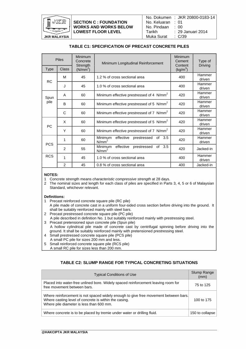
JKR MALAYSIA
SECTION C : FOUNDATION WORKS AND WORKS BELOW LOWEST FLOOR LEVEL
No. DokumenNo. KeluaranNo. PindaanTarikhMuka Surat
: : : : :
JKR 20800-0183-1401 00 29 Januari 2014 C/39
@HAKCIPTA JKR MALAYSIA
TABLE C1: SPECIFICATION OF PRECAST CONCRETE PILES
TABLE C2: SLUMP RANGE FOR TYPICAL CONCRETING SITUATIONS
Typical Conditions of Use Slump Range
(mm)
Placed into water-free unlined bore. Widely spaced reinforcement leaving room for free movement between bars.
75 to 125
Where reinforcement is not spaced widely enough to give free movement between bars. Where casting level of concrete is within the casing. Where pile diameter is less than 600 mm.
100 to 175
Where concrete is to be placed by tremie under water or drilling fluid. 150 to collapse
Piles Minimum Concrete Strength (N/mm2)
Minimum Longitudinal Reinforcement
Minimum Cement Content (kg/m3)
Type of Driving
Type Class
RC M 45 1.2 % of cross sectional area 400
Hammer driven
J 45 1.0 % of cross sectional area 400 Hammer driven
Spun pile
A 60 Minimum effective prestressed of 4 N/mm2 420 Hammer driven
B 60 Minimum effective prestressed of 5 N/mm2 420 Hammer driven
C 60 Minimum effective prestressed of 7 N/mm2 420 Hammer driven
PC X 60 Minimum effective prestressed of 5 N/mm2 420
Hammer driven
Y 60 Minimum effective prestressed of 7 N/mm2 420 Hammer driven
PCS 1 60
Minimum effective prestressed of 3.5 N/mm2
420 Hammer driven
2 55 Minimum effective prestressed of 3.5 N/mm2
420 Jacked-in
RCS
1 45 1.0 % of cross sectional area 400 Hammer driven
2 45 0.8 % of cross sectional area 400 Jacked-in
NOTES: 1 Concrete strength means characteristic compressive strength at 28 days. 2 The nominal sizes and length for each class of piles are specified in Parts 3, 4, 5 or 6 of Malaysian
Standard, whichever relevant. Definitions: 1 Precast reinforced concrete square pile (RC pile)
A pile made of concrete cast in a uniform four-sided cross section before driving into the ground. It shall be suitably reinforced mainly with steel bars.
2 Precast prestressed concrete square pile (PC pile) A pile described in definition No. 1 but suitably reinforced mainly with prestressing steel.
3 Precast pretensioned spun concrete pile (Spun pile) A hollow cylindrical pile made of concrete cast by centrifugal spinning before driving into the ground. It shall be suitably reinforced mainly with pretensioned prestressing steel.
4 Small prestressed concrete square pile (PCS pile) A small PC pile for sizes 200 mm and less.
5 Small reinforced concrete square pile (RCS pile) A small RC pile for sizes less than 200 mm.
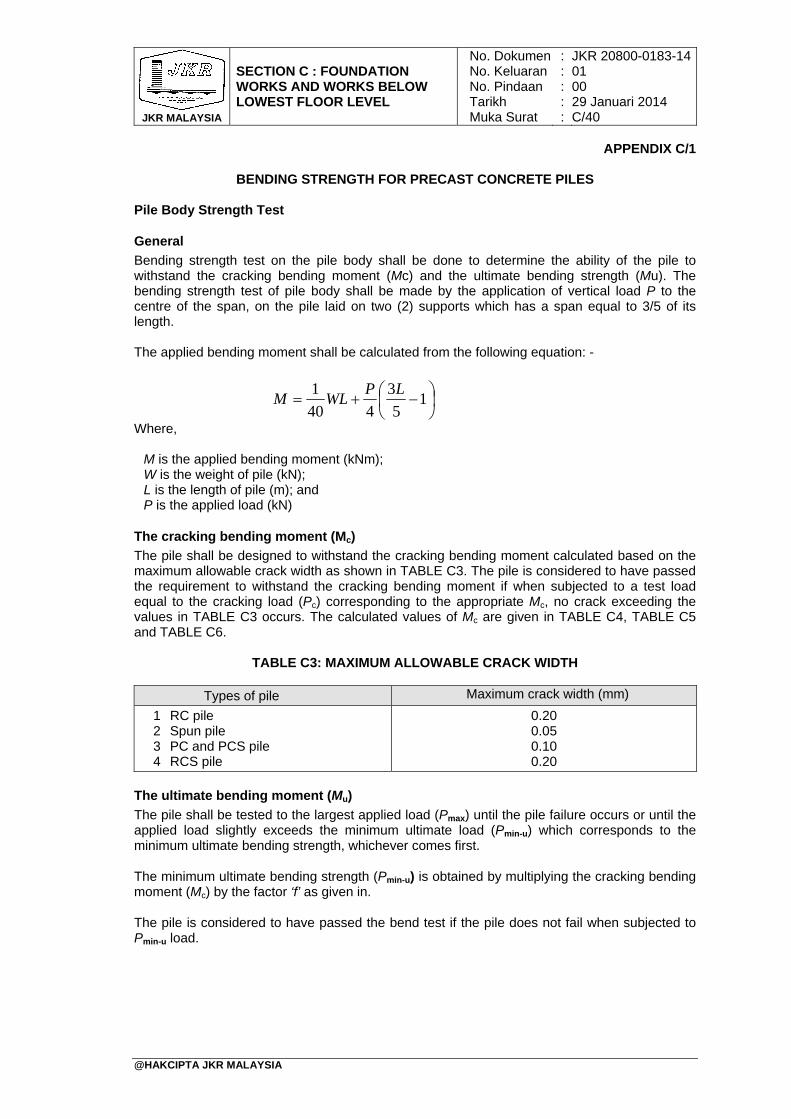
JKR MALAYSIA
SECTION C : FOUNDATION WORKS AND WORKS BELOW LOWEST FLOOR LEVEL
No. DokumenNo. KeluaranNo. PindaanTarikhMuka Surat
: : : : :
JKR 20800-0183-1401 00 29 Januari 2014 C/40
@HAKCIPTA JKR MALAYSIA
APPENDIX C/1
BENDING STRENGTH FOR PRECAST CONCRETE PILES
Pile Body Strength Test
General
Bending strength test on the pile body shall be done to determine the ability of the pile to withstand the cracking bending moment (Mc) and the ultimate bending strength (Mu). The bending strength test of pile body shall be made by the application of vertical load P to the centre of the span, on the pile laid on two (2) supports which has a span equal to 3/5 of its length. The applied bending moment shall be calculated from the following equation: - Where, M is the applied bending moment (kNm); W is the weight of pile (kN); L is the length of pile (m); and P is the applied load (kN)
The cracking bending moment (Mc)
The pile shall be designed to withstand the cracking bending moment calculated based on the maximum allowable crack width as shown in TABLE C3. The pile is considered to have passed the requirement to withstand the cracking bending moment if when subjected to a test load equal to the cracking load (Pc) corresponding to the appropriate Mc, no crack exceeding the values in TABLE C3 occurs. The calculated values of Mc are given in TABLE C4, TABLE C5 and TABLE C6.
TABLE C3: MAXIMUM ALLOWABLE CRACK WIDTH
Types of pile Maximum crack width (mm)
1 RC pile 2 Spun pile 3 PC and PCS pile 4 RCS pile
0.20 0.05 0.10 0.20
The ultimate bending moment (Mu)
The pile shall be tested to the largest applied load (Pmax) until the pile failure occurs or until the applied load slightly exceeds the minimum ultimate load (Pmin-u) which corresponds to the minimum ultimate bending strength, whichever comes first.
The minimum ultimate bending strength (Pmin-u) is obtained by multiplying the cracking bending moment (Mc) by the factor ‘f’ as given in.
The pile is considered to have passed the bend test if the pile does not fail when subjected to Pmin-u load.
1
5
3
440
1 LPWLM
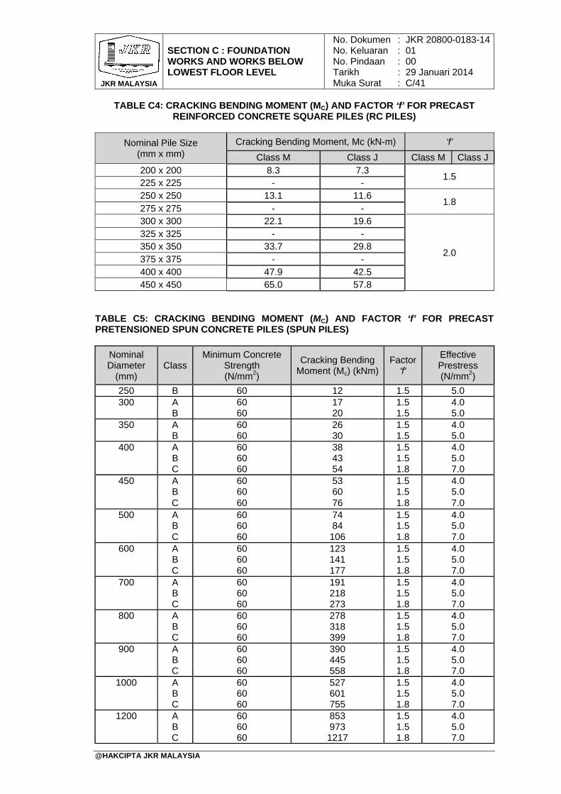
JKR MALAYSIA
SECTION C : FOUNDATION WORKS AND WORKS BELOW LOWEST FLOOR LEVEL
No. DokumenNo. KeluaranNo. PindaanTarikhMuka Surat
: : : : :
JKR 20800-0183-1401 00 29 Januari 2014 C/41
@HAKCIPTA JKR MALAYSIA
TABLE C4: CRACKING BENDING MOMENT (MC) AND FACTOR ‘f’ FOR PRECAST REINFORCED CONCRETE SQUARE PILES (RC PILES)
Nominal Pile Size (mm x mm)
Cracking Bending Moment, Mc (kN-m) ‘f’
Class M Class J Class M Class J 200 x 200 8.3 7.3
1.5 225 x 225 - - 250 x 250 13.1 11.6
1.8 275 x 275 - - 300 x 300 22.1 19.6
2.0
325 x 325 - - 350 x 350 33.7 29.8 375 x 375 - - 400 x 400 47.9 42.5 450 x 450 65.0 57.8
TABLE C5: CRACKING BENDING MOMENT (MC) AND FACTOR ‘f’ FOR PRECAST PRETENSIONED SPUN CONCRETE PILES (SPUN PILES)
Nominal Diameter
(mm) Class
Minimum Concrete Strength (N/mm2)
Cracking Bending Moment (Mc) (kNm)
Factor 'f'
Effective Prestress (N/mm2)
250 B 60 12 1.5 5.0 300 A 60 17 1.5 4.0
B 60 20 1.5 5.0 350 A 60 26 1.5 4.0
B 60 30 1.5 5.0 400 A 60 38 1.5 4.0
B 60 43 1.5 5.0 C 60 54 1.8 7.0
450 A 60 53 1.5 4.0 B 60 60 1.5 5.0 C 60 76 1.8 7.0
500 A 60 74 1.5 4.0 B 60 84 1.5 5.0 C 60 106 1.8 7.0
600 A 60 123 1.5 4.0 B 60 141 1.5 5.0 C 60 177 1.8 7.0
700 A 60 191 1.5 4.0 B 60 218 1.5 5.0 C 60 273 1.8 7.0
800 A 60 278 1.5 4.0 B 60 318 1.5 5.0 C 60 399 1.8 7.0
900 A 60 390 1.5 4.0 B 60 445 1.5 5.0 C 60 558 1.8 7.0
1000 A 60 527 1.5 4.0 B 60 601 1.5 5.0 C 60 755 1.8 7.0
1200 A 60 853 1.5 4.0 B 60 973 1.5 5.0 C 60 1217 1.8 7.0
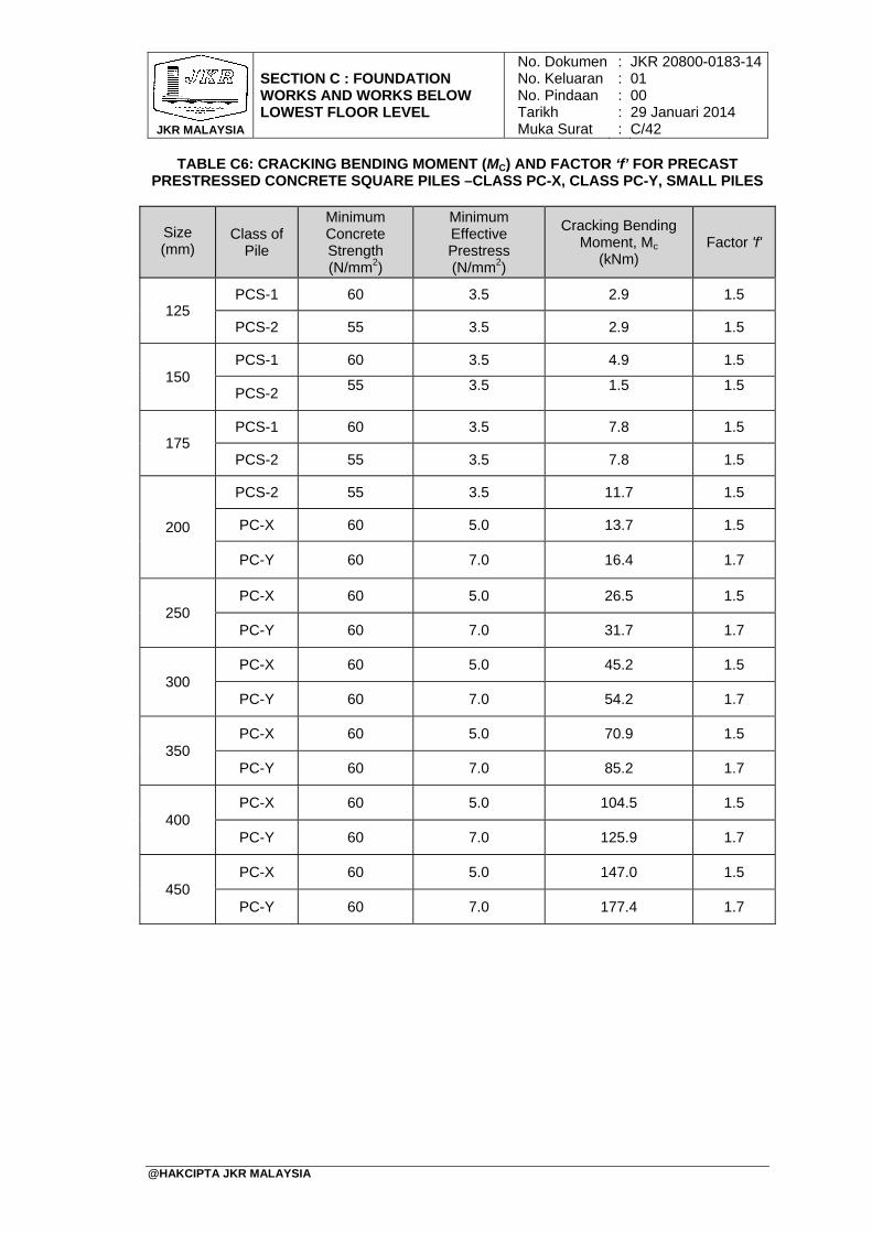
JKR MALAYSIA
SECTION C : FOUNDATION WORKS AND WORKS BELOW LOWEST FLOOR LEVEL
No. DokumenNo. KeluaranNo. PindaanTarikhMuka Surat
: : : : :
JKR 20800-0183-1401 00 29 Januari 2014 C/42
@HAKCIPTA JKR MALAYSIA
TABLE C6: CRACKING BENDING MOMENT (MC) AND FACTOR ‘f’ FOR PRECAST PRESTRESSED CONCRETE SQUARE PILES –CLASS PC-X, CLASS PC-Y, SMALL PILES
Size (mm)
Class of Pile
Minimum Concrete Strength (N/mm2)
Minimum Effective Prestress (N/mm2)
Cracking Bending Moment, Mc
(kNm) Factor 'f'
125 PCS-1 60 3.5 2.9 1.5
PCS-2 55 3.5 2.9 1.5
150 PCS-1 60 3.5 4.9 1.5
PCS-2 55 3.5 1.5 1.5
175 PCS-1 60 3.5 7.8 1.5
PCS-2 55 3.5 7.8 1.5
200
PCS-2 55 3.5 11.7 1.5
PC-X 60 5.0 13.7 1.5
PC-Y 60 7.0 16.4 1.7
250 PC-X 60 5.0 26.5 1.5
PC-Y 60 7.0 31.7 1.7
300 PC-X 60 5.0 45.2 1.5
PC-Y 60 7.0 54.2 1.7
350 PC-X 60 5.0 70.9 1.5
PC-Y 60 7.0 85.2 1.7
400 PC-X 60 5.0 104.5 1.5
PC-Y 60 7.0 125.9 1.7
450 PC-X 60 5.0 147.0 1.5
PC-Y 60 7.0 177.4 1.7
TABLE OF CONTENTS
SECTION D: CONCRETE WORKS
PAGE
@HAKCIPTA JKR MALAYSIA
1. General 2. Material 3. Concrete Conformity And Identity Testing 4. Production Of Concrete 5. Construction With Concrete 6. Steel Reinforcement 7. Formwork And Surface Finish For Structure 8. Mass And Lean Concrete 9. Building Accuracy 10. Apparatus 11. Precast Concrete Construction 12. Other Concrete Works
Figure D1 : Lift Shaft Enclosure Figure D2 : Limit Of Accuracy Of Shaft Plumb On All Sides Of Shaft Enclosure Figure D3 : Accuracy Of Structural Opening Table D1 : Composition Of Common Cements Table D2 : Testing Of Aggregates Table D3 : Grading For Coarse Aggregate Table D3A : Grading For Fine Aggregate Table D4 : Admixture Acceptance Test Requirements Table D5 : Prescribed Mixes For General Use Per Cubic Meter Of Concrete
By Weight Batching Table D5A : Proportion And Strength Requirements For Prescribed Mixes By
Volume Batching Table D6 : Durability Recommendations For Reinforced Or Prestressed
Elements With An Intended Working Life Of At Least 50 Years Table D6A : Minimum Cement Content For Maximum Aggregate Sizes Other
Than 20 mm Table D7 : Slump Classes Table D7A : Compaction Classes Table D7B : Vebe Classes Table D7C : Flow Classes Table D7D : Consistence Suitable For Different Uses Of In-situ Concrete Table D7E : Maximum Total Chloride Table D8 : Compressive Strength Classes For Normal Weight And Heavy
Weight Concrete Table D9 : Compressive Strength Classes For Light Weight Concrete Table D10 : Minimum Rate Of Sampling For Assessing Conformity Table D11 : Conformity Criteria For Compressive Strength Table D12 : Compressive Strength Requirements For Prescribed Mix Table D13 : Identity Criteria For Compressive Strength Table D14 : Identity Criteria For Slump Specified As A Slump Class Table D15 : Identity Criteria For Slump Specified As A Target Value Table D16 : Recorded Data And Other Documents Table D17 : Characteristic Strength Of Steel Reinforcement Table D18 : Minimum Periods Between Concreting And Removal Of Forms
D/1 D/1 D/5 D/10 D/16 D/19 D/22 D/28 D/28 D/28 D/28 D/30 D/31 D/32 D/32 D/35 D/36 D/36 D/36 D/37 D/38 D/38 D/39 D/40 D/40 D/40 D/40 D/40 D/41 D/41 D/41 D/42 D/42 D/42 D/43 D/43 D/43 D/43 D/44 D/44 D/44

JKR MALAYSIA
SECTION D : CONCRETE WORKS
No. DokumenNo. KeluaranNo. PindaanTarikhMuka Surat
: : : : :
JKR 20800-0183-1401 00 29 Januari 2014 D/1
@HAKCIPTA JKR MALAYSIA
1. General
This section shall apply to the construction of all structures or parts of structures to be composed of concrete with or without steel reinforcement. The work shall be carried out all in accordance with this specification and the lines, levels, grades, dimensions and cross-sections shown on the Drawings and as required by the S.O.
2. Material
2.1 Cement 2.1.1 The cement to be used throughout the Work shall be cement obtained from
SIRIM-certified manufacturer. The cement shall be described and complied with MS EN 197-1 as shown in TABLE D1.
2.1.2 Certificates of test
2.1.2.1 Manufacturers' certificates of test shall in general be accepted as
proof of soundness. Additional tests shall be carried out on any cement which appears to have deteriorated through age, damage to containers, improper storage, or any other reason. The test shall be carried out at any approved laboratory in accordance with MS EN 196 at the expense of the Contractor. Any batch of cement that has been sampled and tested and found not to have complied with the requirements shall be rejected and removed from the Site.
2.1.2.2 The S.O. may, without tests being made, order that any bag of
cement, a portion of the contents of which has hardened, or which appears to be defective in any other way, be removed from the Site.
2.1.3 Transportation and storage
The cement shall be transported to the Site in covered vehicles adequately protected against water. It shall be stored in a weatherproof cement store to the approval of the S.O. Cement stored in bags shall not be laid directly on the ground. It shall be taken for use in the Work in the order of its delivery into the store. Cement delivered in bulk shall be stored in purposely built silos of an approved design.
2.2 Aggregates
2.2.1 Aggregates shall be naturally occurring sand, granite or limestone, crushed or
uncrushed, except as otherwise specified, and shall comply with MS EN 12620. They shall be obtained from a source approved by the S.O. Marine aggregates shall not be used.
2.2.2 Coarse aggregates
Coarse aggregates shall comply with MS EN 12620. For work below ground level, only crushed granite shall be used. Unless otherwise specified in the Drawings, tests shall be carried out according to MS 30. The property limits shall be as specified in TABLE D2. The maximum nominal size of aggregate shall be as specified in the Drawings.
JKR MALAYSIA
SECTION D : CONCRETE WORKS
No. DokumenNo. KeluaranNo. PindaanTarikhMuka Surat
: : : : :
JKR 20800-0183-1401 00 29 Januari 2014 D/2
@HAKCIPTA JKR MALAYSIA
2.2.3 Fine aggregates
Fine aggregates shall comply with MS EN 12620. In the context of MS EN 12620, the term 'sand' is used to mean 'fine aggregate'. Unless otherwise specified in the Drawings, tests shall be carried out in accordance with MS 30. The property limits shall be as specified in TABLE D2.
2.2.4 Grading
2.2.4.1 Coarse aggregates
The grading of coarse aggregates shall be analysed as described in MS 30 and shall be within the limits specified in TABLE D3.
2.2.4.2 Fine aggregates
The grading of fine aggregates shall be analysed as described in MS 30 and shall be within the limits specified in TABLE D3A. However, for prescribed mixes Grading Limit M shall only be used.
2.2.5 Sampling and testing of aggregates
Where site mixing is used, samples of fine and coarse aggregates approved by the S.O. shall be kept on Site. These samples shall give a fair indication of the general quality of the aggregates for comparison with the aggregates delivered during the course of executing the work. Tests shall be carried out on samples of the latter, taken at intervals as required by the S.O., or whenever there is a change of source. The appropriate method of sampling and testing shall be in accordance with the standards as specified in TABLE D2. Any batch of aggregate rejected by the S.O. shall be removed from the Site.
2.2.6 Storage of aggregates
2.2.6.1 Separate storage facilities with adequate provision for drainage shall
be provided for each different size of aggregate used.
2.2.6.2 Aggregate shall be handled and stored so as to minimize segregation and contamination.
2.3 Water
Water shall comply with the requirements of MS EN 1008. It shall be clean and free from materials deleterious to concrete in the plastic and hardened state and shall be from a source approved by the S.O. The S.O. may instruct the Contractor to carry out chemical tests at any approved laboratory at the expense of the Contractor. The Contractor shall make adequate arrangement to supply and store sufficient water at the Site for use in mixing and curing of concrete.
2.4 Admixtures
2.4.1 Suitable admixtures may be used in concrete mixes with the prior approval of
or as directed by the S.O.
2.4.2 The admixtures, the sampling and testing of the admixtures and the information to be provided with the admixture supplied shall comply with MS EN 934/ BS EN 934-2
JKR MALAYSIA
SECTION D : CONCRETE WORKS
No. DokumenNo. KeluaranNo. PindaanTarikhMuka Surat
: : : : :
JKR 20800-0183-1401 00 29 Januari 2014 D/3
@HAKCIPTA JKR MALAYSIA
2.4.3 All admixtures shall be used strictly in accordance with manufacturer's recommendation.
2.4.4 Before allowing the admixture to be used in the Work, relevant tests based on trial mixes shall be carried out. A control mix shall be made using a conventional trial mix that is without using the admixture, to determine the free water: cement ratio and mix proportion required to give the specified strength with the required slump. Using the same mix proportion as in the control mix but with a modified water: cement ratio whenever necessary, a test shall be carried out using the recommended dosage of the admixture. The results of the relevant test obtained from the control mix and test mix shall be compared. The S.O. may allow the use of the admixture only when the results are found to be satisfactory and comparable to the effects as claimed by the manufacturer. The admixture acceptance test shall comply with the requirements specified in TABLE D4.
2.4.5 The uses of admixtures that are chloride based are not permitted for structural concrete containing reinforcement, prestressing tendons or other embedded metal. The Contractor shall submit documentary evidence on the contents of the admixture to be used.
2.4.6 When the Contractor proposes the use of super-plasticiser, special control
tests shall be carried out with prior approval of the S.O. The tests shall be carried out in accordance with the latest standard and the manufacturer's recommendations.
2.4.7 If two or more admixtures are proposed to be used simultaneously in the same concrete mix, the Contractor shall furnish the S.O. with supporting data on their suitability and compatibility.
2.5 Classification Of Concrete Mixes
2.5.1 The concrete mix shall be designed concrete to MS523-1 and MS523-2
unless otherwise stated in the Drawings. However, prescribed concrete may be used subject to the following:
(i) The work is of minor nature or involving a small quantity of concrete, (ii) Prior approval is given by the S.O., (iii) The Contractor shall be responsible for the strength of the concrete (iv) Only CEM I cement is specified to be used
2.5.2 When other than CEM I cement is specified to be used, the concrete mix shall
be of designed concrete only.
2.6 Prescribed Concrete
2.6.1 Prescribed concrete shall conform to MS 523-1 and MS 523-2. Prescribed concrete shall be as detailed in TABLE D5. The mix prescribed in the table does not require the use of admixture.
2.6.2 For small volume concreting work, volume batching is permitted provided prior approval of the S.O. is obtained. The proportion shall be as specified in TABLE D5A.
JKR MALAYSIA
SECTION D : CONCRETE WORKS
No. DokumenNo. KeluaranNo. PindaanTarikhMuka Surat
: : : : :
JKR 20800-0183-1401 00 29 Januari 2014 D/4
@HAKCIPTA JKR MALAYSIA
2.7 Designed Concrete
2.7.1 Designed concrete shall comply with the recommendations of MS523-1 and MS 523-2. The minimum cement content and maximum free water: cement ratio to be used shall be as shown on TABLE D6 and D6A.
2.7.2 The Contractor shall comply with the following requirements:
(i) Notify the S.O. whether the designed concrete is to be produced as site- mixed or ready-mixed.
(ii) If the Contractor chooses to use ready mix concrete, he shall notify the S.O. the name of the supplier, location of the ready mix plant, journey time taken to transport the concrete to the Site and production capacity of the plant
(iii) Submit a mix design report covering all concrete mixes to the S.O. for approval. The designed concrete shall comply with the requirements specified in TABLE D6 and D6A.
(iv) The Contractor shall ensure that the S.O. be permitted to visit or station his representative at the plant at any stage of the concrete production
2.8 Requirements For Concrete
2.8.1 Concrete grade
The grade of concrete to be used in the work shall be as stated in the Drawings and /or in the B.Q. (Concrete shall be designated as Grade X/Y where 'X' is minimum characteristic cylinder strength in N/mm2, and 'Y' is minimum characteristic cube strength in N/mm2. For prescribed mix, a suffix 'P' shall be added after 'X').
2.8.2 Cement content
2.8.2.1 Cement content in this specification shall refer to the total quantities
of cement as approved in sub-section 2.1, or the total quantities of cementitious materials comprising Portland cement and other constituents complying to MS EN 197-1.
2.8.2.2 Minimum cement content
The minimum cement content shall be in accordance with TABLE D6 and D6A, unless otherwise shown on the Drawings
2.8.2.3 Maximum cement content
The maximum cement content shall not exceed 550 kg/m3 unless otherwise shown on the Drawings or as approved by the S.O.
2.8.3 Consistence
2.8.3.1 The consistence of the fresh concrete shall be judged by its
suitability for the condition of handling and placing so that after compaction, it surrounds all reinforcement, tendons and ducts and completely fills the formwork. Consistence of the concrete shall be within one of the following limits: (i) Slump classes (Refer to TABLE D7) (ii) Compacting classes (Refer to TABLE D7A)
JKR MALAYSIA
SECTION D : CONCRETE WORKS
No. DokumenNo. KeluaranNo. PindaanTarikhMuka Surat
: : : : :
JKR 20800-0183-1401 00 29 Januari 2014 D/5
@HAKCIPTA JKR MALAYSIA
(iii) Vebe classes (Refer to TABLE D7B) (iv) Flow classes (Refer to TABLE D7C)
2.8.3.2 Unless otherwise specified in the Drawings, consistence values
expressed as slump and flow classes appropriate to different uses of concrete shall be as given in TABLE D7D.
2.8.4 Total chloride content
The total chloride content of the concrete mix arising from the aggregate or any other source shall not in any circumstances exceed the limits in TABLE D7E expressed as a percentage relationship between chloride ions and weight of cement in the mix. When necessary, tests shall be carried out in accordance with BS 1881: Part 124 for each grade of concrete, to demonstrate that these limits are not exceeded.
2.8.5 Maximum sulphate content
The total estimated sulphate content of any mix, including that present in the cement shall not exceed 4% by weight of cement in the mix. Where necessary, tests shall be carried out in accordance with BS 1881: Part 124 for each grade of concrete to demonstrate that this limit is not exceeded.
3. Concrete Conformity And Identity Testing
3.1 Evaluation Of Conformity 3.1.1 General
3.1.1.1 The contractor is responsible for the evaluation of conformity for
specified requirements of the concrete. For this purpose, the contractor shall carry out the following tasks: (i) Initial test, (ii) Production control including conformity control
3.1.2 Concrete composition and initial testing
3.1.2.1 In the case of using a new concrete composition, initial testing shall
be performed to provide a concrete that achieves the specified properties or intended performance with an adequate margin. The concrete design and design relationships shall be re-established in the case of a prescribed concrete.
3.1.2.2 New concrete composition shall be reviewed periodically to provide assurance that all concrete designs are still in accordance with the actual requirements, taking account of the change in properties of the constituent materials and the results of conformity testing on the concrete compositions.
3.1.3 Initial tests
3.1.3.1 Frequency of initial tests
Initial test shall be repeated if there has been a significant change either in the constituent materials or in the specified requirements on which the previous test were based.
JKR MALAYSIA
SECTION D : CONCRETE WORKS
No. DokumenNo. KeluaranNo. PindaanTarikhMuka Surat
: : : : :
JKR 20800-0183-1401 00 29 Januari 2014 D/6
@HAKCIPTA JKR MALAYSIA
3.1.3.2 Test conditions
(i) In general, initial test shall be carried out on fresh concrete with a temperature 27±2ºC
(ii) For the initial test of single concrete, at least three specimens from each of three batches shall be tested.
(iii) The strength of a batch or load shall be taken to be the average
of the test results. The result of the initial test on the concrete is the average strength of the batches or loads.
3.1.3.3 Criteria for adoption of initial tests
(i) For assessing the properties of concrete, in particular those of fresh concrete, the differences between the type of mixer and mixing procedure applied during the initial test and those applied during actual production shall be taken into account.
(ii) The compressive strength of the concrete with the composition to be adopted for the actual case shall exceed the values fck of TABLE D8 or TABLE D9 by an adequate margin. This margin shall be at least that need to satisfy the conformity criteria given in sub-section 4.2.1.3. The margin should be about twice the expected standard deviation, that means at least a margin of 6 N/mm2 to 12 N/mm2 depending on the production facilities, the constituent materials and the available background information about the variation.
(iii) The consistence of the concrete shall be within the limits of the consistence class, at the time at which the concrete likely to be placed or in the case of ready mixed concrete, delivered.
(iv) For other properties that are specified, the concrete shall meet the specified values with an appropriate margin.
3.2 Conformity Control For Designed Concrete
3.2.1 Conformity control for compressive strength
3.2.1.1 General
(i) For normal-weight and heavy-weight concrete of strength classes from C8/10 to C55/67 or light-weight concrete from LC8/9 to LC55/60, sampling and testing shall be performed on individual concrete compositions.
(ii) In the sampling and testing plan and the conformity criteria of individual concrete compositions distinction is made between initial production and continuous production.
(iii) Initial production covers the production until at least 35 test results are available.
(iv) Continuous production is achieved when at least 35 test result are obtained over a period not exceeding 12 months.
JKR MALAYSIA
SECTION D : CONCRETE WORKS
No. DokumenNo. KeluaranNo. PindaanTarikhMuka Surat
: : : : :
JKR 20800-0183-1401 00 29 Januari 2014 D/7
@HAKCIPTA JKR MALAYSIA
(v) If production of an individual concrete composition, has been suspended more than 12 months, the criteria, sampling and testing plan given for initial production shall be adopted.
(vi) During continuous production, the sampling and testing plan and the criteria for initial production may be adopted.
(vii) If the strength is specified for a different age, the conformity is assessed on specimens tested at the specified age.
(viii) Identity testing shall be carried out in accordance to 4.4 in order to verify that a defined volume comes from a conforming population.
3.2.1.2 Sampling and Testing
(i) Samples of concrete shall be randomly selected and taken in accordance with EN 12350-1. The minimum rate of sampling and of testing of concrete shall be in accordance with TABLE D10 at the rate that gives the highest number of samples for initial or continuous production, as appropriate.
(ii) The samples shall be taken after any water or admixtures are added to the concrete, but sampling before adding plasticizer to adjust the consistence is permitted where there is proof by initial testing that the plasticizer or super plasticizer in quality to be used has no negative effect on the strength of the concrete.
(iii) The test result shall be that obtained from an individual specimen or the average of the results when two or more specimens made from one sample are tested at the same age.
(iv) Where two or more specimens are made from one sample and the range of the test values is more than 15 % of the mean the result shall be disregarded unless an investigation reveals an acceptable reason to justify disregarding an individual test value.
3.2.1.3 Conformity criteria for compressive strength
(i) Conformity assessment shall be made be made on test results
taken during an assessment period that shall not exceed the last twelve months.
(ii) Conformity of concrete compressive strength is assessed on specimens tested at 28 days in accordance with :
a) Groups of n non-overlapping or overlapping consecutive
test results fcm (Criterion 1) b) Each individual test result fa (Criterion 2)
(iii) Conformity is confirmed if both the criteria given in TABLE D11 for either initial or continuous production are satisfied.
(iv) Initially, the standard deviation shall be calculated from at least 35 consecutive test results taken over a period exceeding three months and which is immediately prior to the production period during which conformity is to be checked. This value shall be
JKR MALAYSIA
SECTION D : CONCRETE WORKS
No. DokumenNo. KeluaranNo. PindaanTarikhMuka Surat
: : : : :
JKR 20800-0183-1401 00 29 Januari 2014 D/8
@HAKCIPTA JKR MALAYSIA
taken as the estimate of the standard deviation (σ) of the population. The validity of the adopted value shall be verified during the subsequent production using Method 1 as stated below. However, Method 2 may be used if approved by the S.O.
a) Method 1
The initial value of standard deviation may be applied for the subsequent period during which conformity is to be checked, provided the standard deviation of the latest 15 results (s15) does not deviate significantly from the adopted standard deviation. This is considered valid provided: 0.63 σ ≤ s15≤1.37 σ Where the value of s15 lies outside these limits, a new estimate of σ shall be determined from last available 35 test results
b) Method 2
The new value of σ may be estimated from a continuous system and this value is adopted. The sensitivity of the system shall be at least that of Method 1.
3.3 Non-conformity Of Product
3.3.1 The following actions shall be taken by the Contractor in the event of non-
conformity:
(i) Check test results and if invalid, take action to eliminate errors; (ii) If non-conformity is confirmed e.g. by retesting, take corrective actions
including a management review of relevant production control procedures;
(iii) Where there is confirmed non-conformity with the specification that was not obvious at delivery, notice shall be given to the S.O. in order to avoid any consequential damage;
(iv) Record actions on the items above
3.3.2 If the Contractor has given notice of non-conformity of the concrete or if the results of conformity tests do not fulfil the requirements, supplementary testing according to EN 12504-1 on cores taken from the structure or components or a combination of tests on cores and non-destructive tests on the structure or in structural components as given in EN 13791 shall be required by the S.O.
3.4 Identity Testing
3.4.1 General
Identity testing indicates whether the defined volume of concrete in question belongs to the same population as that verified as conforming with the characteristic strength via conformity assessment.
JKR MALAYSIA
SECTION D : CONCRETE WORKS
No. DokumenNo. KeluaranNo. PindaanTarikhMuka Surat
: : : : :
JKR 20800-0183-1401 00 29 Januari 2014 D/9
@HAKCIPTA JKR MALAYSIA
3.4.2 Identity testing for compressive strength
3.4.2.1 Sampling and testing plan
(i) The sampling rate for identity testing shall be as follows:
a) One sample per 10.0 m3 or every group of 10 batches for critical structures e.g. prestressed concrete, masts, cantilevers, columns, footing, pile caps, shear wall, retaining wall.
b) One sample per 20.0m3 or every group of 20 batches e.g. slabs, beams.
c) One sample per 50.0 m3 or every group of 50 batches e.g. raft foundation and mass concrete.
(ii) Samples shall be taken from different batches or loads in
accordance with EN 12350-1 Test specimens shall be prepared and cured in accordance with EN 12390-2. The compressive strength of the specimens shall be determined in accordance with EN 12390-3 The test result shall be that obtained from the average of the results of two or more specimens made from one sample for testing at the same age. Where the range of test values is more than 15% of the mean, the results shall be disregarded unless an investigation reveals an acceptable to justify disregarding an individual test value.
3.4.2.2 Cube strength at 7 days
One cube from each sample batch shall be tested for the seven (7) days compressive strength. The cube compressive strength shall not fall below the corresponding values given in TABLE D12 for prescribed concrete, and two-third (2/3) of the twenty eight (28) days compressive strength for designed concrete.
3.4.3 Identity criteria for compressive strength
3.4.3.1 Concrete under production control certification
(i) Identity of concrete is assessed for each individual strength test
result and the average non-overlapping discrete results as identified in TABLE D13.
(ii) Concrete is deemed to come from a conforming population if
both the criteria in TABLE D13 are satisfied for n results derived from strength tests on samples taken from the defined volume of concrete.
3.4.3.2 Concrete not under production control certification
From the defined volume of concrete, at least three (3) samples shall be taken for testing. The concrete is deemed to come from a conforming population if the conformity in sub-section 4.2.1.3 and TABLE D11 for initial production is satisfied.
JKR MALAYSIA
SECTION D : CONCRETE WORKS
No. DokumenNo. KeluaranNo. PindaanTarikhMuka Surat
: : : : :
JKR 20800-0183-1401 00 29 Januari 2014 D/10
@HAKCIPTA JKR MALAYSIA
3.4.4 Identity testing for slump and flow
3.4.4.1 Sampling and testing plan
(i) The sampling shall be either: a) In accordance with MS26-1-1; or
b) Measured using a spot sample obtained from the initial
discharge, if concrete is delivered in a truck mixer or agitating equipment. The spot sample shall be taken after a discharge of approximately 0.3 m3 by taking six increments from the moving stream of the concrete in accordance with MS 26-1-1.
(ii) The sample shall be remixed on a non-absorbent surface and
tested for slump or flow. Slump shall be measured in accordance with MS 26-1-2. Flow shall be measured in accordance with MS 26-1-5.
3.4.5 Identity criteria for the slump of an individual batch
If the measured slump meets the requirements specified in TABLE D14 or is within the tolerance specified in TABLE D15, the identity test confirms that the batch conforms to MS 523: Part 1 with respect to consistence. For identity criteria for flow reference shall be made to Annex B of MS523-2.
4. Production Of Concrete 4.1 General
4.1.1 All concrete shall be subjected to production control under the responsibility of
the contractor.
4.1.1.1 Production control comprises all measures necessary to maintain the properties of concrete in conformity to specified requirements. It includes: (i) selection of materials. (ii) concrete design. (iii) concrete production. (iv) inspection and tests. (v) the use of the results of test on constituent materials, fresh and
hardened concrete and equipment. (vi) For ready-mixed concrete, inspection of equipment used in
transporting fresh concrete.
4.2 Production Control System
The production control system shall contain adequately documented procedures and instructions. These procedures and instructions shall, where relevant, be established in respect of the control requirement as given in the TABLES D10, D11 and D16.
4.3 Supervision
The Contractor shall ensure the required standard of control over materials and workmanship. The S.O. shall be afforded all reasonable opportunities and facilities to
JKR MALAYSIA
SECTION D : CONCRETE WORKS
No. DokumenNo. KeluaranNo. PindaanTarikhMuka Surat
: : : : :
JKR 20800-0183-1401 00 29 Januari 2014 D/11
@HAKCIPTA JKR MALAYSIA
inspect the constituent materials and the production of concrete and to take samples for testing.
4.4 Site Mixed Concrete
4.4.1 The quantities of cement, fine aggregate and various sizes of coarse
aggregate shall be measured by weight unless otherwise approved by the S.O. A separate weighing machine shall be provided for weighing the cement. Alternatively, the cement may be measured by using a whole number of bags in each batch. The quantity of water shall be measured by volume or by weight. Any solid admixtures to be added shall be measured by weight; liquid or paste admixtures shall be measured by volume or weight.
4.4.2 The batch weight of aggregate shall be adjusted to allow for the moisture content of the aggregate being used. All measuring equipment shall be calibrated on site or their calibration status established by certificates from accredited laboratories.
4.4.3 The mixing time shall be not less than two minutes and not more than five minutes or any other time recommended by the mixer manufacturer after all the ingredients have been placed in the mixer.
4.4.4 Mixers that have been out of use for more than 30 minutes shall be thoroughly cleaned before any fresh concrete is mixed. Unless otherwise agreed by the S.O., the first batch of concrete through the mixer shall contain only two thirds of the normal quantity of coarse aggregate. The mixer shall be thoroughly cleaned before changing from one type of cement to another.
4.4.5 The water content of each batch of concrete may be adjusted so as to produce concrete of the workability required. However care shall be taken to ensure the free water: cement ratio is maintained. The total amount of water added to the mix shall be recorded.
4.5 Ready Mixed Concrete
4.5.1 Ready mixed concrete are batched, either dry or wet, at a control plant and
transported in purpose-made agitators operating continuously or truck mixers to the Site.
4.5.2 Ready mixed concrete shall comply with the requirements of designed concrete as in sub-section 3.2 and MS 523-1. All concrete materials, including water and admixtures shall be mixed in the plant and delivered to Site in purpose made truck mixers. No extra water or admixtures are allowed to be added after the concrete has left the plant.
4.5.3 Ready mixed concrete delivered to the Site shall be accompanied by delivery ticket and manufacturer's batching record stating the details of mix proportions by weight, the grade of concrete, type and size of aggregate, date and time of loading at plant, type and dosage of chemical admixtures and other relevant production details in suitable format, failing which the S.O, or his representative, shall immediately reject the total load of the concrete. The S.O, or his representative, and the contractor shall ensure the information provided in the delivery tickets and the manufacturer's batching record complies with the details of the approved 'designed concrete' and its corresponding consistence as in sub-section 3.2.1 before discharging the concrete.
JKR MALAYSIA
SECTION D : CONCRETE WORKS
No. DokumenNo. KeluaranNo. PindaanTarikhMuka Surat
: : : : :
JKR 20800-0183-1401 00 29 Januari 2014 D/12
@HAKCIPTA JKR MALAYSIA
4.5.4 Rejected concrete shall be removed from the Site. The delivery ticket shall be marked 'REJECTED'.
4.6 Transporting
Concrete shall be transported from the mixer to the formwork as rapidly as practicable by methods, which will prevent segregation or loss of any constituents or ingress of foreign matter or water and maintain the required workability. It shall be deposited as near as practicable in its final position to avoid rehandling or moving the concrete horizontally by vibration. The concrete shall be conveyed by chutes or concrete pumps only with permission from the S.O.
4.7 Placing
4.7.1 Placing of concrete in dry condition
4.7.1.1 For all concrete whether mixed on or off the site of the Work, each
batch shall be placed and compacted within two (2) hours of adding the cement to the dry aggregates and within 45 minutes (or any other period of time based on the trial mix as per sub-sections 2.4 and 3.2.3 and approved by the S.O. if an admixture is used) of adding water to the cement and aggregate. Concrete shall not be placed in any part of the structure until the approval of the S.O. has been obtained. If concreting is not started within 24 hours of approval given, approval shall again be obtained from the S.O.
4.7.1.2 All formwork and reinforcement contained in it shall be clean and free from standing water immediately before the placing of concrete. Concreting shall be carried out continuously between and up to predetermined construction joints in one sequence of operation. It shall be thoroughly compacted by either hand tamping or mechanical vibration or both and shall be thoroughly worked into the corners. After tamping into place the concrete shall not be subjected to disturbance other than such as incidental to compaction by vibration. In the event of unavoidable stoppage in positions not predetermined, the concreting shall be terminated on a horizontal plane and against vertical surfaces by the use of stop boards. The location for termination shall be subjected to the approval of the S.O.
4.7.1.3 Fresh concrete shall not be placed against in-situ concrete which has been in position for more than 45 minutes unless a construction joint is formed in accordance with sub-section 6.1. When in-situ concrete has been in place for four hours, no further concrete shall be placed against it for a further 20 hours. Where retarding admixture has been used, the S.O. may approve variation to this limit.
4.7.1.4 Except where otherwise approved by the S.O., concrete shall be deposited in horizontal layers to a compacted depth not exceeding 450 mm when internal vibrators are used or 300 mm in all other cases. The surface of the concrete shall be maintained reasonably level during placing.
4.7.1.5 Concrete shall not be dropped into place from a height exceeding 1.5 m. However, higher drops may be allowed provided the mix has been well designed and proportioned. When trunking or chutes are used, they shall be kept clean and used in such a manner as to avoid segregation.
JKR MALAYSIA
SECTION D : CONCRETE WORKS
No. DokumenNo. KeluaranNo. PindaanTarikhMuka Surat
: : : : :
JKR 20800-0183-1401 00 29 Januari 2014 D/13
@HAKCIPTA JKR MALAYSIA
4.7.1.6 The Contractor shall maintain an experienced steel fixer at the site of reinforced concrete works during the placing of concrete to reposition any reinforcement which may be displaced.
4.7.2 Placing of concrete under water
4.7.2.1 No concrete shall be placed in flowing water. Underwater concrete if
deemed unavoidable, shall be placed in position by Tremie pipes from the mixer. During and after concreting under water, pumping or dewatering operations in the immediate vicinity shall be suspended until the S.O. permits them to continue. Where the concrete is placed by a Tremie pipe, the following requirements shall be applicable: -
(i) The hopper and tremie pipe shall be a closed system. The
bottom of the Tremie pipe shall be kept as far as practicable beneath the surface of the placed concrete.
(ii) The tremie pipe shall be large enough with due regard to the
size of aggregate. For 20 mm aggregates, the Tremie pipe shall be of a diameter not less than 150 mm and for larger aggregates, a bigger diameter Tremie pipe approved by the S.O. shall be used.
(iii) Unless otherwise agreed by the S.O., the first charge of
concrete shall be placed with a sliding plug pushed down the Tremie pipe ahead of it to prevent mixing of concrete and water.
(iv) The Tremie pipe shall always penetrate well into the concrete
with an adequate margin of safety against accidental withdrawal if the pipe is surged to discharge the concrete.
(v) The concrete shall be deposited wholly by Tremie pipe and the
method of deposition shall not be changed part way up to prevent the laitance from being entrapped within the structure.
(vi) All Tremie pipes shall be properly cleaned after use.
4.8 Placement Temperature
4.8.1 Placement temperature shall comply with MS 523-3 to prevent premature
setting and loss of water during placing of concrete in the formwork and the following precautions shall be taken:
(i) At the time of placing, no part of the concrete shall have a temperature
exceeding 36°C. This may be achieved by cooling the water and aggregate prior to mixing.
(ii) Concrete shall not be placed in forms or around reinforcement whose temperature exceeds 36°C. This can be achieved by providing shading or other means to protect from direct sunlight.
(iii) Freshly placed concrete shall be protected from direct sunlight and from
loss of moisture by covering, shading or other means. (iv) No concrete shall be placed when the air temperature at the point of
deposition exceeds 36°C
4.8.2 However, higher temperatures may be allowed if specified in the Drawings.
JKR MALAYSIA
SECTION D : CONCRETE WORKS
No. DokumenNo. KeluaranNo. PindaanTarikhMuka Surat
: : : : :
JKR 20800-0183-1401 00 29 Januari 2014 D/14
@HAKCIPTA JKR MALAYSIA
4.9 Compaction
4.9.1 Unless otherwise approved by the S.O., concrete shall be thoroughly compacted by vibration and thoroughly worked around the reinforcement, tendons or duct formers, around embedded fixtures and into corners of the formwork to form a dense, homogenous mass, free from voids and which will have the required surface finish when the formwork is removed. Vibration shall be applied continuously during the placing of each batch of concrete until the expulsion of air has practically ceased and in a manner which does not promote segregation of the ingredients.
4.9.2 The concrete maintained between the two walls of formwork shall be compacted by internal or external vibrators. Concrete in slabs with no formwork on its upper surface shall be compacted either by vibrators of the pan type or by a vibrating screen.
4.9.3 The internal vibrators shall be inserted and withdrawn slowly and at a uniform pace of approximately 100 mm per second. Compaction shall be deemed to be completed when cement mortar appears in an annulus around the vibrator. Over vibration leading to segregation of the mix must be avoided. The internal vibrators shall be inserted at points judged by the area of mortar showing after compaction, with a certain allowance made for overlapping and they shall not be allowed to come into contact with the formwork or the reinforcement and shall be inserted at a distance of not less than 75 mm from the formwork.
4.9.4 The pan vibrator shall be placed on the surface of the concrete, which shall have previously been tamped and leveled leaving an allowance in height for compaction until the cement mortar appears under the pan. The vibrator shall then be lifted and placed on the adjoining surface and this operation shall be repeated until the whole surface has been compacted. Alternatively, a vibrating screen spanning the full width of the surface may also be used.
4.9.5 Whenever vibration has to be applied externally, the design of formwork and disposition of vibration shall receive special consideration to ensure efficient compaction and to avoid surface blemishes. The vibration shall be such that there will be no excess water on the top surface on completion of compaction.
4.9.6 External vibrators shall be firmly secured to the formwork which must be sufficiently rigid to transmit the vibration and strong enough not to be damaged by it. Internal vibrators shall be capable of operating at not less than 10,000 cycles per minute and external vibrators at not less than 3,000 cycles per minute. Sufficient vibrators in serviceable condition shall be on Site so that spare equipment is always available in the event of breakdowns. Vibrators shall be operated by workmen skilled in their use.
4.9.7 Concrete shall not be subjected to any disturbance within 24 hours after compaction. No standing or flowing water shall be allowed to come into contact with exposed concrete surfaces during the first two (2) hours after placing and compaction of the concrete.
4.9.8 In the event where inadequate or improper compaction is suspected, the S.O. has the right to inspect and to carry out further tests. The tests may include non-destructive and destructive methods. All expenses incurred in carrying out such sampling, testing and remedial works shall be borne by the Contractor irrespective of whether the tests prove the structure to be sound or otherwise.
JKR MALAYSIA
SECTION D : CONCRETE WORKS
No. DokumenNo. KeluaranNo. PindaanTarikhMuka Surat
: : : : :
JKR 20800-0183-1401 00 29 Januari 2014 D/15
@HAKCIPTA JKR MALAYSIA
4.10 Curing And Protection
4.10.1 All concrete work shall be cured for the full period of curing which shall not be less than five (5) days for F1, F2, F3 and F4 surfaces, but not less than three (3) days for F11, F12, F13, F14 and F15 surfaces.
4.10.2 Curing and protection shall start immediately after compaction of the concrete
to protect it from:
(i) Impact damage such as shock, overloading or falling earth which may disrupt the concrete and interface with its bond to reinforcements.
(ii) Premature drying out from direct sunlight and wind. (iii) Leaching out by rain and flowing water. (iv) High internal thermal gradients.
4.10.3 Normal curing and protection
4.10.3.1 Concrete, after it is placed and until the expiration of the curing
duration, shall not be allowed to dry out. Provision shall be made for adequate protection against direct sunlight and wind to allow the process of curing to complete within the specified period.
4.10.3.2 Curing and protection shall be accomplished by covering the exposed concrete surface with an impermeable material such as polyethylene sheet, which should be well sealed and fastened and if required, this treatment can be continued efficiently throughout the whole period of curing.
4.10.3.3 When the concrete has attained its final set, one of the following curing methods shall be adopted:
(i) Water curing shall be accomplished by keeping the surface of
the concrete continuously wet by ponding with water. (ii) Curing may be accomplished by sealing in the water as specified
above by covering with an approved waterproofed curing paper or plastic sheeting laid with airtight joints. It must be securely positioned to prevent displacement by wind and protected from tearing or other injury.
4.10.3.4 The use of other methods of curing may be deemed necessary when
the concrete is subjected to high internal thermal gradient, or with large exposed surface area. The Contractor shall submit a method statement to the approval of the S.O.
4.10.3.5 In the event where the Contractor does not do proper curing, the S.O. has the right to inspect and to carry out further tests which may include destructive methods. All expenses incurred in carrying out such sampling, testing and remedial works shall be borne by the Contractor irrespective of whether the tests proved the structure to be sound or otherwise.
4.10.4 Accelerated curing
4.10.4.1 Elevated temperature curing may be used only with Ordinary
Portland Cement.
4.10.4.2 After the completion of the placing of concrete, four (4) hours shall elapse before its temperature is raised, unless the Contractor is able

JKR MALAYSIA
SECTION D : CONCRETE WORKS
No. DokumenNo. KeluaranNo. PindaanTarikhMuka Surat
: : : : :
JKR 20800-0183-1401 00 29 Januari 2014 D/16
@HAKCIPTA JKR MALAYSIA
to prove that curing can start earlier by furnishing all the relevant supporting data to the S.O. The rise in temperature within any period of 30 minutes shall not exceed 10°C and maximum temperature attained shall not exceed 70°C unless it can be proven that any deviation from this provision shall not result in any detrimental effect to the concrete work. The rate of subsequent cooling shall not exceed the rate of heating. The use of accelerated curing methods for concrete containing other types of cement or any admixture or any additional materials shall be to the approval of the S.O.
5. Construction With Concrete 5.1 Construction Joints
5.1.1 Construction joints shall be made at the location as shown on the drawing and
concreting work shall be carried out continuously up to the construction joints. If the position and detail of any construction joints is not described in the drawings, the Contractor shall propose and obtain the approval of the S.O. prior to commencement of concreting. The construction joints shall be made as few as possible with reasonable precautions against shrinkage. The joints shall be at right angles to the general direction of the member and shall take due account of shear and other stresses.
5.1.2 Concrete shall not be allowed to run to a feather edge and vertical joints shall be formed against a stop end. The top surface of a layer of concrete shall be level and flat unless design considerations make this undesirable. Joint lines shall be so arranged that they coincide with features of the finished work, wherever possible.
5.1.3 At horizontal construction joints, gauge strips about 25 mm width shall be
placed inside the forms along all exposed surfaces to ensure a straight joint on those surfaces. Where a kicker (that is a starter stub) is used for the construction of walls and columns, it shall be at least 75 mm high, to be constructed monolithically with the base concrete.
. 5.1.4 Where vertical construction joints are necessary in mass concrete structures,
reinforcing bars shall be placed across the joints so as to make the structure monolithic, all to the approval of the S.O.
5.1.5 Prior to recommencement of concreting on a joint, the surface of the concrete against which new concrete will be cast shall be free from laitance and shall be roughened to the extent that the coarse aggregate is exposed but not disturbed. Care shall be taken to avoid damaging the lines of the joint. Care shall also be taken that the joint surface is clean and damp but not wet and the exposed adjoining surfaces shall be of consistent colour. Immediately before the fresh concrete is placed against the joint, fresh rich cement mortar (1:2) shall be applied to the exposed surface.
5.1.6 Where the S.O. considers that special preparation is necessary, e.g. for an in-
situ structural connection, preparation shall be carried out, preferably when the concrete has set but not hardened, by spraying with a fine spray of air and water or brushing with a stiff brush sufficiently to remove the outer mortar skin and expose the larger aggregates without disturbing them. Where this treatment is impracticable, sand blasting or a needle gun shall be used to remove the surface skin and laitance. Hardened surfaces shall be chipped manually or mechanically to be free from laitance and properly roughened to the extent that the coarse aggregates are being exposed.

JKR MALAYSIA
SECTION D : CONCRETE WORKS
No. DokumenNo. KeluaranNo. PindaanTarikhMuka Surat
: : : : :
JKR 20800-0183-1401 00 29 Januari 2014 D/17
@HAKCIPTA JKR MALAYSIA
5.2 Fixing Blocks, Brackets, Built In Bolts, Holes, Chases, Et Cetera 5.2.1 All fixing blocks, brackets, built in bolts, holes, chases, et cetera shall be
accurately set out and formed and carefully sealed prior to the concrete being placed. It is the responsibility of the Contractor to obtain all such information for these items of work and to obtain the approval of the S.O. before incorporating such work prior to the concrete being placed.
5.2.2 Bolts and other inserts to be cast into the concrete shall be securely fixed to the formwork in such a way that they are not displaced during the concreting operations and that there is no loss of materials from the wet concrete through holes in the formwork.
5.2.3 Unless otherwise shown on the Drawings or instructed by the S.O.,
reinforcement shall be locally moved so that the minimum specified cover is maintained at the locations of inserts, holes, chases, et cetera. In the event where the minimum cover cannot be maintained, the Contractor shall take the necessary precautions to protect the reinforcements against corrosion by applying an approved coating materials to the reinforcements and the concrete cover.
5.2.4 Temporary plugs shall be removed and the threads of built in bolts shall be
cleaned and greased before handing over any part of the Work.
5.3 Movement Joints. 5.3.1 Movement Joints, Expansion joints, contraction joints or other permanent
structure joints shall be provided in the positions and constructed and sealed with waterproofing materials as detailed in the Drawings.
5.3.2 When forming movement joints, joint filler shall be fixed firmly to the first-placed concrete. If more than one strip is used within a joint, it is essential to butt the ends tightly or tape them together to prevent grout leakage restricting the closure of the joint.
5.3.3 It is essential that the concrete on both sides of the joint, when placed, is
thoroughly compacted to form a dense uniform mass. Where stop ends comprise more than one element, particular care is necessary to ensure that joints between elements are sufficiently tight to allow no grout loss through them during compaction of the concrete.
5.3.4 Where flexible water stops are used, they shall be fixed so as to ensure that
they are not displaced from their intended position during compaction of the concrete and that the concrete surrounding them is fully compacted. The design of the water stop should be practical and take account of the problems often associated with integral water stop construction in difficult placing conditions.
5.3.5 Water stops laid horizontally and located within the concrete mass shall be
avoided since they attract the greatest risk of local honeycombing.
5.3.6 Unless otherwise shown on the Drawings, all exposed expansion joints shall be covered with 0.7 mm thick aluminium cover strips fixed with masonry nails at 300 mm centers.
JKR MALAYSIA
SECTION D : CONCRETE WORKS
No. DokumenNo. KeluaranNo. PindaanTarikhMuka Surat
: : : : :
JKR 20800-0183-1401 00 29 Januari 2014 D/18
@HAKCIPTA JKR MALAYSIA
5.4 Sealants And Special Materials
5.4.1 General
The installation method and the selection, mixing, application and curing of all joint waterproofing materials shall be in accordance with the manufacturer's recommendations. The Contractor may propose to use alternative joint waterproofing materials by submitting supporting technical information, test reports and samples of the proposed waterproofing materials to the S.O. for approval
5.4.2 Waterproofing materials
All waterproofing materials used at public access areas shall be protected with non-shrink grout covering
5.4.3 Water stops
5.4.3.1 Water stops shall be as specified in the Drawings and shall be
installed and butt jointed according to BS 8007 and the manufacturer's recommendation.
5.4.3.2 Water stops shall be securely positioned in the formwork to prevent
displacement during concreting.
5.4.4 Two-part polysulphide or two-part polyurethane sealant
5.4.4.1 Two-part polysulphide or two-part polyurethane sealant for external use shall comply with the following requirements: (i) Conformance to BS 4254 (ii) Minimum joint movement capacity of ± 27.5% of joint width at
27.5ºC; (iii) Shore 'A' Hardness of 25 ± at 27.5ºC; (iv) Resistance to dilute acids, alkali and all kind of fuel
5.4.5 Preformed flexible strip sealant
5.4.5.1 Preformed flexible strip sealant shall comply with the following
requirements:
(i) Shall only be used in horizontal joints and be subjected to pressure
(ii) throughout its length; (iii) Good adhesion (iv) Water resistant (v) Non-staining
5.4.6 Bitumen/rubber cold applied membrane
5.4.6.1 Bitumen/rubber cold applied membrane shall comply with the
following requirements: (i) Minimum joint movement capacity of ±10% of joint width at
27.5ºC (ii) 90% solid content; (iii) Resistant to dilute acid and alkali.
JKR MALAYSIA
SECTION D : CONCRETE WORKS
No. DokumenNo. KeluaranNo. PindaanTarikhMuka Surat
: : : : :
JKR 20800-0183-1401 00 29 Januari 2014 D/19
@HAKCIPTA JKR MALAYSIA
5.4.7 Hot-poured rubber/bitumen sealing compound
Hot-poured rubber/bitumen sealing compound shall comply with BS 2499.
5.4.8 Bituminous sheeting
5.4.8.1 Bituminous sheeting with non-asbestos fibre shall comply with the following requirements: (i) Resistant to lime water (no visual effect after two (2) weeks
immersion) (ii) Maximum water absorption of 10% of dry weight (iii) Minimum tensile strength of 50 kg/cm² (iv) Ozone and ultraviolet resistant
5.4.9 Neoprene bearing pads
5.4.9.1 Neoprene bearing pads shall comply with the following requirements:
(i) Shore 'A' Hardness of 60 ± 5 at 27.5oC (ii) Minimum rupture strength of 105 kg/cm² (iii) Minimum rupture elongation of 300%.
5.4.10 Polyurethane foam backing rods
5.4.10.1 Polyurethane foam backing rods used as sealant stops in panel
joints shall have the following properties: - (i) Minimum compressibility of 75% of original volume at 27.5oC (ii) Excellent resilient properties; (iii) Density between 35 kg/cm³ and 45 kg/cm³ (iv) Total resistance to common acids, lubricants and detergents (v) Total resistance to water infiltration by capillary action (vi) Suitability for up to 70oC.
6. Steel Reinforcement 6.1 General
The Work shall consist of furnishing and placing reinforcing steel in accordance with this specification and in conformity with the Drawings or as directed by the S.O.
6.2 Materials
6.2.1 Hot rolled mild steel and high yield bars shall comply with the requirements of
MS 146. Cold worked steel bars shall comply with the requirements of BS 4461. Hard drawn mild steel wire shall comply with the requirements of MS 144.
6.2.2 Steel fabric reinforcement shall comply with the requirements of MS 145 and shall be delivered to the Site in flat sheets, unless otherwise specified.
6.2.3 Dowel bars shall be plain, round bars conforming to the requirements of MS 146. They shall be free from burring or other deformations restricting slippage in the concrete. Dowel bar sleeves used for debonding shall be of approved synthetic material. The closed end of the sleeve shall be filled with 25 mm thick compressible foam fillers and the sleeve shall fit tightly over the length of the bar to be debonded.
JKR MALAYSIA
SECTION D : CONCRETE WORKS
No. DokumenNo. KeluaranNo. PindaanTarikhMuka Surat
: : : : :
JKR 20800-0183-1401 00 29 Januari 2014 D/20
@HAKCIPTA JKR MALAYSIA
6.2.4 Before any reinforcement steel is brought to Site, the Contractor shall furnish the mill certificates of tests and these shall be submitted for acceptance by the S.O. In addition Contractor shall on request, furnish the S.O. with a test sheet from approved laboratories for any batch of bars, giving the results of each of the mechanical tests and/or chemical composition analysis required under the MS or any equivalent international standards approved by the S.O. The specified characteristic strength of steel reinforcement shall be as given in TABLE D17.
6.2.5 During the course of the work, any reinforcement found to be not in accordance with the MS or BS may be rejected by the S.O. notwithstanding any previous acceptance on the strength of the test certificates. The S.O. may call for additional tests to be made at the Contractor's expense on samples taken from the batch of the defective reinforcement. If the samples do not comply with the MS or BS, then the S.O. may reject the whole batch and instruct its removal from the Site.
6.2.6 Steel reinforcement shall be stored in clean and dry conditions. When placed in the work it shall be clean and free from loose rust, mill scale, oil, grease, paint, dirt or anything which may reduce its bond with concrete. If directed by the S.O., the steel bars shall be brushed or otherwise cleaned before use, at the Contractor's expense.
6.2.7 Binding wire shall be 1.6 mm diameter soft annealed steel wire complying with the requirements of BS 1052.
6.3 Construction Methods
6.3.1 Cutting and bending of reinforcement
6.3.1.1 Bars shall be of their correct lengths and bent to the exact shapes
required before being fixed in the work.
6.3.1.2 Bars shall be cut and bent cold by the application of slow, steady pressure or in an approved bar-bending machine. Bending at temperatures in excess of 100ºC may only be carried out with the S.O.'s approval and under his supervision. Except where otherwise indicated in the Drawings, bars shall be bent and measured in accordance with BS 4449.
6.3.1.3 Cold worked and hot rolled bars shall not be straightened or bent again once having been bent. Where it is necessary to bend the free end of mild steel reinforcement already cast in the concrete, the internal radius of the bend shall not be less than twice the diameter of the bar.
6.3.1.4 Special care shall be taken that the overall length of bars with multiple bends is accurate and that after bending and fixing in position the bars remain in place without wrap or twist.
6.3.2 Fixing of reinforcement
6.3.2.1 The number, size, length, shape, type and position of all reinforcing
bars, links, spacer bars and other parts of the steel reinforcement, shall be in accordance with the Drawings.
6.3.2.2 Reinforcements shall be secured against displacement. Unless specified otherwise, the actual concrete cover shall be taken as the
JKR MALAYSIA
SECTION D : CONCRETE WORKS
No. DokumenNo. KeluaranNo. PindaanTarikhMuka Surat
: : : : :
JKR 20800-0183-1401 00 29 Januari 2014 D/21
@HAKCIPTA JKR MALAYSIA
distance between face of concrete and the nearest steel surface. All intersecting bars shall be tied together with binding wire and the ends of the wire shall be turned into the main body of the concrete.
6.3.2.3 Reinforcement temporarily left projecting from the concrete at construction or other joints shall not be bent out of position during the periods in which concreting is suspended except with the approval of the S.O.
6.3.2.4 The Contractor shall take particular care that the reinforcement is laid out correctly in every aspect and temporarily suspended by annealed wire or supported on concrete blocks or other approved spacers in the forms to prevent displacement during the placing and compacting of concrete. Links shall tightly embrace the longitudinal reinforcement to which they shall be securely wired or spot welded. The top reinforcement in slabs shall be rigidly supported on mild steel 'chairs' or equivalent spaced in each direction to prevent sagging during concreting.
6.3.2.5 No concrete shall be placed until the reinforcement has been inspected and approved by the S.O.
6.3.3 Splicing
6.3.3.1 Joints to reinforcement bars shall be effected by lapping of bars at
positions shown on the Drawings. Where other types of joints are to be used, prior approval of the S.O shall be obtained and their use shall be strictly in accordance with manufacturer's recommendation, at the positions approved by the S.O.
6.3.4 Supporting and spacer blocks
6.3.4.1 The size of supporting and spacer blocks required for ensuring that
the reinforcement is correctly positioned shall be not more than 50mm x50mm consistent with their purpose, of a shape approved by the S.O., and designed so that they will not overturn when the concrete is placed.
6.3.4.2 The nominal size of aggregates used shall be 10 mm. The concrete spacers shall be of at least the same strength and material's source as the concrete to be poured. Wires cast in these blocks for the purpose of tying them to the reinforcement shall be as described in sub-section 7.2.
6.3.4.3 Spacers left in situ shall not impair the desired appearance or durability of the structure by causing spalling, rust staining or allowing the passage of moisture.
6.3.4.4 Other types of spacers may be used only with the approval of the S.O.
6.3.5 Welding of reinforcement
6.3.5.1 Welding workmanship, including welder qualification shall comply
with sub-section 5 of JKR Standard Specification for structural Steel Work JKR No. 200600-0019-99.
JKR MALAYSIA
SECTION D : CONCRETE WORKS
No. DokumenNo. KeluaranNo. PindaanTarikhMuka Surat
: : : : :
JKR 20800-0183-1401 00 29 Januari 2014 D/22
@HAKCIPTA JKR MALAYSIA
6.3.5.2 Reinforcement in structures shall not be welded except where detailed in the Drawings or permitted in this specification.
6.3.5.3 Welding shall be carried out in accordance with BS EN 1011 and BS EN 60974. Butt welds shall be of the double V type and two butt weld bond tests shall be carried out on a specimen prepared to represent each form of the butt welded joint used in welding the reinforcement and for each position of welding. The method of making butt weld tests shall be as laid down in BS EN 17637. The specimen shall pass the test to the approval of the S.O. before using the joint, which the specimen represents. Welded joints shall not be made at bends in reinforcement. Unless otherwise approved by the S.O., joints in parallel bars of the principal tensile reinforcement shall be staggered in the longitudinal direction at a distance not less than the end anchorage length for the bar.
6.3.5.4 The S.O. shall be informed in advance of when welding is to be carried out so that he may supervise and inspect the work. Welding shall not be performed in the field during rain or other adverse conditions.
7. Formwork And Surface Finish For Structure 7.1 Design And Construction
7.1.1 Description
7.1.1.1 Formwork shall include all temporary or permanent forms required
for forming the concrete, together with all temporary construction required for their support.
7.1.1.2 The Contractor is deemed to have made a study of the Drawings at tender stage and is aware of all areas of construction, requiring heavy and specially designed propping to provide the support and the necessary bracing for the stability of such propping.
7.1.1.3 The design and construction of formwork shall be carried out by a competent person. The Contractor shall identify all critical formwork design and submit the strength and deflection calculations and Drawings or the proposed design, certified by a Professional Engineer to the S.O. for prior approval. Notwithstanding any approval by the S.O. with respect to the design submitted by the Contractor, the responsibility or the adequacy and safety of the design shall remain with the Contractor. The Contractor shall also appoint a competent formwork coordinator whose duties would be similar to those outlined in BS 5975.
7.1.1.4 When the use of proprietary type of formwork is proposed by the Contractor, the design shall be certified by a Professional Engineer.
7.1.1.5 The formwork shall be sufficiently rigid and tight to prevent loss of grout or mortar from the concrete at all stages of construction and shall be appropriate for the methods of placing and compacting.
7.1.1.6 Formwork (including supports) shall be sufficiently rigid to maintain the forms in their correct position, shape, profile and dimensions. The supports shall be designed to withstand the worst combination of forces due to self-weight, formwork weight, formwork forces,
JKR MALAYSIA
SECTION D : CONCRETE WORKS
No. DokumenNo. KeluaranNo. PindaanTarikhMuka Surat
: : : : :
JKR 20800-0183-1401 00 29 Januari 2014 D/23
@HAKCIPTA JKR MALAYSIA
reinforcement weight, wet concrete weight, construction and wind loads, together with all incidental dynamic effects caused by placing, vibrating and compacting the concrete. Guidance on these loadings is given in The Concrete Society Manual Formwork - Guide to good practice, and in CIRIA Report 108, Concrete Pressure in Formwork, and in BS 5975. Vertical propping to formwork shall be carried down sufficiently far to provide the necessary support without overstressing the completed concrete structure.
7.1.1.7 Metal ties may only be used with the prior approval of the S.O. Where metal ties are permitted, the use of storey height steel soldiers shall be used to reduce the number of tie bolts required. Tie bolts with rubber or plastic cone against the form face are to be used to prevent unsightly grout loss. No metal part of any device for maintaining formwork in the correct location shall remain permanently within the specified concrete cover to the reinforcement. Except for ties used for anchoring void formers, all ties shall be at least 1.2 m apart and through bolts will not be permitted on exposed form finished faces. All holes left by ties shall be made good within one day of the removal of the formwork using a mortar of the same strength as the cast concrete. Metal ties which allow for holes through the concrete being cast shall not be permitted to be used in concrete for water-retaining structure, roof slabs and walls.
7.1.1.8 The formwork shall be so arranged as to be readily dismantled and removed from the cast concrete without shock, disturbance or damage. Where necessary, the formwork shall be so arranged that the soffit form, properly supported, can be retained in position for such period as may be required by the condition of the maturing concrete or the specification. If a component is to be prestressed whilst still resting on the soffit form, provision shall be made to allow for elastic deformation and any variation in weight distribution. As far as practicable, formwork joints shall coincide with construction joints.
7.1.2 Form lining
7.1.2.1 The type and treatment of any lining (plywood, metal, plastic,
Controlled Permeability Formwork liner, et cetera) of the forms shall be appropriate to the concrete finish required.
7.1.2.2 The Controlled Permeability Formwork (CPF) liner shall have the following requirements:
(i) The requirement for a special finish shall be as for traditional
formwork finishes except that the formwork shall be covered by a CPF liner.
(ii) CPF liner shall be used on all surfaces as detailed on the Drawings
(iii) The CPF liner shall be a Water Bylaws Scheme - Approved Product for use with potable water in accordance with BS 6920.
(iv) The CPF liner shall have the following properties: a) Compression of less than 10% under a pressure 200 kPa. b) Maximum pore size of less than 0.030 mm. c) Minimum water retention capacity of 0.35 l/m2. d) Result in bleed water from the liner which is free from
cement and fine aggregate particles.
JKR MALAYSIA
SECTION D : CONCRETE WORKS
No. DokumenNo. KeluaranNo. PindaanTarikhMuka Surat
: : : : :
JKR 20800-0183-1401 00 29 Januari 2014 D/24
@HAKCIPTA JKR MALAYSIA
(v) The concrete cast against the CPF liner shall have an even uniformly textured matt finish and shall be free of blowholes and other surface blemishes. The use of the CPF liner shall meet the following performance requirements which should be demonstrated by the supply of test certificate: a) The mean surface strength for the CPF cast face shall
exceed that for the control face by at least 70%. b) The mean 10 minute ISAT result for the CPF cast face shall
be not more than 15% of that for the control face. c) The mean depth of carbonation for the CPF cast face shall
be not more than 15% of that for the control face. d) The mean concentration of chlorides at a depth of 11mm
from the CPF cast face shall be not more than 15% of that for the control face.
(vi) The CPF liner shall be used once only. Release agents shall
not be used with the liner and any residual release agent remaining on forms from previous use shall be removed.
(vii) To ensure conformity with the performance requirements, the CPF liner is to be used in accordance with the manufacturer's technical guidelines.
(viii) The CPF liner shall unless otherwise directed, be left in place on the concrete after formwork removal for the curing period specified by the S.O. It shall be kept wet and covered with plastic sheeting to promote efficient curing.
7.1.3 Projecting reinforcement, fixing devices
Where holes are needed in form to accommodate projecting reinforcement or fixing devices, care shall be taken to prevent loss of grout when concreting or damage when removing forms
7.2 Surface Finishes For Concrete
7.2.1 Control of colour
When specified in the Drawings, the Contractor shall obtain each constituent material from a single consistent source. The aggregates shall be free of any impurities that may cause staining. The mix proportions and the grading, particularly of the fine aggregate, shall be maintained constant. The same type of plywood or timber shall be used in formwork throughout similar exposed areas.
7.2.2 Formed surfaces
7.2.2.1 Formed concrete surfaces shall have one of the following classes of
finish.
7.2.2.2 Unless otherwise specified, all exposed concrete surfaces shall be of Class F12, all unexposed surfaces shall be of Class F1. Other classes of finishes shall be used only where shown on the Drawings:
JKR MALAYSIA
SECTION D : CONCRETE WORKS
No. DokumenNo. KeluaranNo. PindaanTarikhMuka Surat
: : : : :
JKR 20800-0183-1401 00 29 Januari 2014 D/25
@HAKCIPTA JKR MALAYSIA
(i) Class F1
This finish shall be obtained by the use of properly designed forms of closely joined sawn timber or other approved material. Small blemishes caused by entrapped air or water may be expected but the surface shall be free from voids and honeycombing.
(ii) Class F2
This finish shall be obtained by the use of properly designed forms of closely jointed wrought boards, approved plywood or other approved material. Only very minor surface blemishes shall occur, with no staining or discoloration.
(iii) Class F3
a) This finish shall be obtained by the use of properly designed steel forms or plastic coated plywood or wrought boards or other approved material.
b) The surface shall be improved by carefully removing all fins and other projections, thoroughly washing down and then filling the most noticeable surface blemishes with a cement and fine aggregate paste to match the colour of the original concrete. Form release agents shall be carefully chosen to ensure that the surface shall not be stained or discolored. After the concrete has been properly cured, the surface shall be rubbed down where necessary, to produce a smooth and even surface.
(iv) Class F4
The requirements for Class F4 are as for Class F3 except that internal ties and embedded metal parts will be permitted. The ties shall be positioned only in rebates, or in other positions as shown on the Drawings or as agreed by the S.O.
(v) Class F11
The requirements for Class F11 surface finish are identical to those for Class F1 except that it shall be achieved using Controlled Permeability Formliners.
(vi) Class F12
The requirements for Class F12 surface finish are identical to those for Class F2 except that it shall be achieved using Controlled Permeability Formliners.
(vii) Class F13
The requirements for Class F13 surface finish are identical to those for Class F3 except that it shall be achieved using Controlled Permeability Formliners.
JKR MALAYSIA
SECTION D : CONCRETE WORKS
No. DokumenNo. KeluaranNo. PindaanTarikhMuka Surat
: : : : :
JKR 20800-0183-1401 00 29 Januari 2014 D/26
@HAKCIPTA JKR MALAYSIA
(viii) Class F14
The requirements for Class F14 surface finish are identical to those for Class F4 except that it shall be achieved using Controlled Permeability Formliners.
(ix) Class F15
The requirements for Class F15 are as for Class F4 except that plywood shutters lined with an approved patterned formliner shall be used to produce a patterned profile finish. Where possible, full height formliners shall be employed so that no horizontal joints in the liners are required. Tie holes shall be spaced so that they occur at overlap joints in the lining sheet.
7.2.3 Unformed surfaces
7.2.3.1 Class U1
The concrete shall be uniformly leveled and screened to produce a plain, ridged or broom roughened surface. No further work shall be applied to the surface unless it is used as the first stage for a Class U2 or Class U3 finish.
7.2.3.2 Class U2
After the concrete has hardened sufficiently, the concrete Class U1 surface shall be floated by hand or machine to produce a uniform surface free from screed marks.
7.2.3.3 Class U3
When the moisture film has disappeared and the concrete has hardened sufficiently to prevent laitance from being worked to the surface, a Class U1 surface shall be steel-trowelled under firm pressure to produce a dense, smooth uniform surface free from trowel marks.
7.2.3.4 Class U4
This finish is for surfaces that are to receive waterproofing systems. The concrete shall be levelled and floated to produce a uniform surface and immediately before the waterproofing operation this surface shall be water jetted or grit blasted to provide a lightly textured finish. The finished surface shall not deviate from the required profile by more than 5 mm over a 3 m gauge length or have any abrupt irregularities of more than 3 mm.
7.2.4 Trial panels for exposed form finished surfaces
7.2.4.1 In order to ensure that the specified formed finishes can be obtained
by the method of construction proposed and to provide a standard by which the finishes in the Works can be assessed, trial panels shall be cast on Site. These panels shall be subjected to the S.O.'s approval before similar casting is permitted in the Works.
7.2.4.2 The trial panels shall employ the materials, plant and concrete mix proposed for the Works. They shall be at least a storey height and 1
JKR MALAYSIA
SECTION D : CONCRETE WORKS
No. DokumenNo. KeluaranNo. PindaanTarikhMuka Surat
: : : : :
JKR 20800-0183-1401 00 29 Januari 2014 D/27
@HAKCIPTA JKR MALAYSIA
m wide. They shall be of similar thickness and similarly reinforced as the elements they represent and shall incorporate all features which contribute to the final appearance of the Works.
7.3 Preparation Of Forms Before Concreting
7.3.1 Before concreting, all forms shall be thoroughly cleaned out, free from
sawdust shavings, dust, mud or other debris. The inside surfaces of forms shall, unless otherwise approved by the S.O., be coated with an approved non-staining form oil or other approved material to prevent adhesion of the concrete Such release agents shall be applied strictly in accordance with the manufacturer's recommendation and shall not come into contact with the reinforcement or prestressing tendons and anchorages. For any exposed surface only one release agent shall be used throughout the entire area.
7.3.2 All formwork shall be inspected by the S.O. after preparation and immediately prior to depositing concrete and no concrete shall be deposited until approval of the formwork has been obtained
7.4 Removal Of Forms
7.4.1 The Contractor shall inform the S.O. and obtain his approval before striking
any formwork, but such approval shall not relieve the Contractor of his responsibilities for the safety of the work.
7.4.2 Formwork shall be removed without such shock or vibration as would damage
the concrete. A period of time shall elapse between the placing of the concrete and the removal of the formwork for various parts of the structure so as to suit the requirements for its curing.
7.4.3 The minimum periods between concreting and the removal of forms are given in TABLE D18. The periods stated in this table are based on the use of Ordinary Portland Cement. They may be changed with the approval of the S.O., if other types of cement as described in sub-section 2.1, admixtures as described in sub-section 2.4 are used. The result of the compressive strength obtained from cube strength at 7 days as described in sub-section 4.4.2.2 may also be used for early removal of forms provided always the Contractor provide proof of calculation to the S.O for approval.
7.4.4 For prestressed in-situ components, temporary supports shall not be removed until the components is stressed to the approval of the S.O.
7.4.5 Where it is intended that forms are to be reused, they shall be cleaned and made good to the approval of the S.O.
7.4.6 Following the removal of forms, no further loads shall be imposed upon the concrete until at least after the completion of the curing period or until such later time as in the opinion of the S.O. the concrete shall have attained sufficient strength to safely withstand such loads. Full design loads shall not be applied to any structure until all load bearing concrete is at least 28 days old.
7.5 Inspection And Making Good
7.5.1 The surface of the concrete shall be inspected for defects and for conformity
to the surface finish specified and where appropriate, with approved sample finishes.
JKR MALAYSIA
SECTION D : CONCRETE WORKS
No. DokumenNo. KeluaranNo. PindaanTarikhMuka Surat
: : : : :
JKR 20800-0183-1401 00 29 Januari 2014 D/28
@HAKCIPTA JKR MALAYSIA
7.5.2 Subject to the strength and durability of the concrete being unimpaired, the making good of surface defects may be permitted but the level of acceptance shall be appropriate to the type and quality of the finish specified and ensure satisfactory permanence and durability.
7.5.3 Any remedial treatment of surfaces shall be approved by the S.O. following inspection immediately after removing the formwork and shall be carried out without delay.
8. Mass And Lean Concrete Mass and lean concrete shall consist of cement, fine aggregate and coarse aggregate in the nominal ratio by volume of 1:3:6 and 1:4:8 respectively. However where a denser and more workable concrete can be produced by a variation in the ratio of the fine aggregate to that of coarse aggregate, this ratio may be varied within the limits (1:1½) and (1:3), provided that the volumes of fine and coarse aggregate, each measured separately, shall nevertheless equal the sum of the volumes of fine and coarse aggregate appropriate to the nominal mix. The concrete shall be mixed as described for reinforced concrete.
9. Building Accuracy
After removal of formwork, the Contractor shall take measurements as directed by the S.O. to check the deviation of the reinforced concrete works from specified dimensions shown on the Drawings. All measurements shall be recorded and submitted to the S.O. Any deviation in building accuracy shall comply with BS EN 13670.
10. Apparatus
10.1 The Contractor shall provide the following apparatus for use on the Site at all times: (i) Concrete slump test apparatus or flow test apparatus complying with MS 26. One
set of the apparatus shall be provided for each concreting location. (ii) At least twelve (12) numbers of steel or cast iron moulds for casting 150 mm
concrete test cubes and six (6) numbers of 100 mm mortar or grout test cube moulds complete with tamping bars and base plates in accordance with MS 26. A minimum number shall be provided such that no stripping of cubes is required prior to 24 hours setting and hardening period.
(iii) Three (3) measuring cylinders of 250 ml capacity, graduated to measure to the nearest 2.0 ml., for determination of silt content (field setting method).
(iv) An approved apparatus for measuring moisture content in fine aggregate. (v) One (1) electronic calculator with statistical functions. (vi) One (1) 300 mm steel rule. (vii) One (1) set of sieves in compliance with BS 410. (viii) Scale or balance 25 kg maximum capacity and weights. (ix) Trowel, shovel, spanner and other tools
11. Precast Concrete Construction 11.1 Manufacture Off Site
11.1.1 After the method of manufacture has been approved, no changes shall be
made without the approval of the S.O.
JKR MALAYSIA
SECTION D : CONCRETE WORKS
No. DokumenNo. KeluaranNo. PindaanTarikhMuka Surat
: : : : :
JKR 20800-0183-1401 00 29 Januari 2014 D/29
@HAKCIPTA JKR MALAYSIA
11.1.2 The Contractor shall inform the S.O. in advance of the date of commencement of manufacture and casting of each type of precast concrete component.
11.1.3 When the S.O. requires tests to be carried out, none of the precast concrete components to which the tests relate shall be dispatched to the site until the tests have been completed and the results approved by the S.O.
11.1.4 All precast concrete components shall be indelibly marked to show the identification marking as specified in the Drawings, the production batch on which they were manufactured and the date on which the concrete was cast. If the components are symmetrical, the face that will be uppermost when the member is in its correct position in the work shall be clearly identified.
11.2 Storage
11.2.1 When the precast concrete components are stored, they shall be firmly
supported only at the points specified in the Drawings. No accumulation of trapped water and deleterious matter shall be allowed in the components. Care shall be taken to avoid rust staining and efflorescence.
11.2.2 The precast concrete components shall be stacked in such a manner that their removal in correct order of age is facilitated.
11.3 Handling And Transport
The precast concrete components shall be lifted only at points specified in the Drawings or otherwise approved by the S.O. and shall be handled and placed without impact. The method of lifting, the type of equipment and transport to be used, and the minimum age of the components to be handled shall be to the approval of the S.O.
11.4 Assembly And Erection
11.4.1 The method of assembly and erection specified in the Drawings shall be
strictly adhered to on site.
11.4.2 Immediately a unit of precast concrete component is in position, and before the lifting equipment is removed, temporary supports or connections between components as necessary, shall be provided. The final structural connections shall be completed as soon as is practicable.
11.5 Forming Structural Connections
11.5.1 For structural purposes, cement mortar shall compose of one (1) part of
cement to one (1) part of sand (1:1), mixed with water so that the free water: cement ratio does not exceed 0.4 by weight and cement grout shall have a water: cement ratio between 0.4 and 0.6, or such other proportions as shall be directed by the S.O.
11.5.2 No structural connections shall be made until approval has been given by the S.O.
11.5.3 Unless otherwise approved by the S.O., the composition and the free water: cement ratio of the in-situ concrete or mortar used in any connection and the packing of joints shall be in accordance with the assembly instructions.
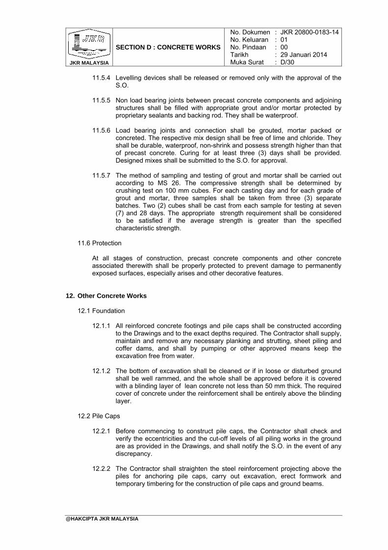
JKR MALAYSIA
SECTION D : CONCRETE WORKS
No. DokumenNo. KeluaranNo. PindaanTarikhMuka Surat
: : : : :
JKR 20800-0183-1401 00 29 Januari 2014 D/30
@HAKCIPTA JKR MALAYSIA
11.5.4 Levelling devices shall be released or removed only with the approval of the S.O.
11.5.5 Non load bearing joints between precast concrete components and adjoining structures shall be filled with appropriate grout and/or mortar protected by proprietary sealants and backing rod. They shall be waterproof.
11.5.6 Load bearing joints and connection shall be grouted, mortar packed or concreted. The respective mix design shall be free of lime and chloride. They shall be durable, waterproof, non-shrink and possess strength higher than that of precast concrete. Curing for at least three (3) days shall be provided. Designed mixes shall be submitted to the S.O. for approval.
11.5.7 The method of sampling and testing of grout and mortar shall be carried out according to MS 26. The compressive strength shall be determined by crushing test on 100 mm cubes. For each casting day and for each grade of grout and mortar, three samples shall be taken from three (3) separate batches. Two (2) cubes shall be cast from each sample for testing at seven (7) and 28 days. The appropriate strength requirement shall be considered to be satisfied if the average strength is greater than the specified characteristic strength.
11.6 Protection
At all stages of construction, precast concrete components and other concrete associated therewith shall be properly protected to prevent damage to permanently exposed surfaces, especially arises and other decorative features.
12. Other Concrete Works 12.1 Foundation
12.1.1 All reinforced concrete footings and pile caps shall be constructed according
to the Drawings and to the exact depths required. The Contractor shall supply, maintain and remove any necessary planking and strutting, sheet piling and coffer dams, and shall by pumping or other approved means keep the excavation free from water.
12.1.2 The bottom of excavation shall be cleaned or if in loose or disturbed ground shall be well rammed, and the whole shall be approved before it is covered with a blinding layer of lean concrete not less than 50 mm thick. The required cover of concrete under the reinforcement shall be entirely above the blinding layer.
12.2 Pile Caps
12.2.1 Before commencing to construct pile caps, the Contractor shall check and
verify the eccentricities and the cut-off levels of all piling works in the ground are as provided in the Drawings, and shall notify the S.O. in the event of any discrepancy.
12.2.2 The Contractor shall straighten the steel reinforcement projecting above the piles for anchoring pile caps, carry out excavation, erect formwork and temporary timbering for the construction of pile caps and ground beams.
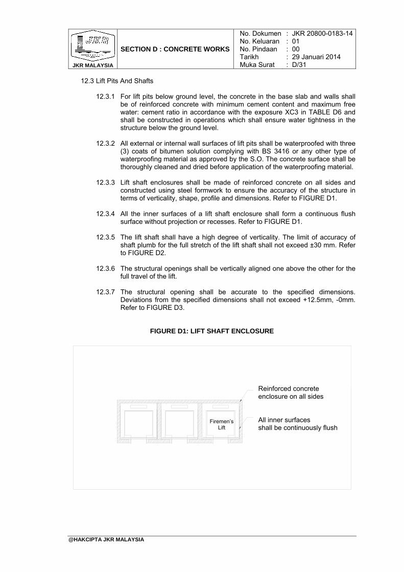
JKR MALAYSIA
SECTION D : CONCRETE WORKS
No. DokumenNo. KeluaranNo. PindaanTarikhMuka Surat
: : : : :
JKR 20800-0183-1401 00 29 Januari 2014 D/31
@HAKCIPTA JKR MALAYSIA
12.3 Lift Pits And Shafts
12.3.1 For lift pits below ground level, the concrete in the base slab and walls shall be of reinforced concrete with minimum cement content and maximum free water: cement ratio in accordance with the exposure XC3 in TABLE D6 and shall be constructed in operations which shall ensure water tightness in the structure below the ground level.
12.3.2 All external or internal wall surfaces of lift pits shall be waterproofed with three (3) coats of bitumen solution complying with BS 3416 or any other type of waterproofing material as approved by the S.O. The concrete surface shall be thoroughly cleaned and dried before application of the waterproofing material.
12.3.3 Lift shaft enclosures shall be made of reinforced concrete on all sides and
constructed using steel formwork to ensure the accuracy of the structure in terms of verticality, shape, profile and dimensions. Refer to FIGURE D1.
12.3.4 All the inner surfaces of a lift shaft enclosure shall form a continuous flush
surface without projection or recesses. Refer to FIGURE D1. 12.3.5 The lift shaft shall have a high degree of verticality. The limit of accuracy of
shaft plumb for the full stretch of the lift shaft shall not exceed ±30 mm. Refer to FIGURE D2.
12.3.6 The structural openings shall be vertically aligned one above the other for the
full travel of the lift. 12.3.7 The structural opening shall be accurate to the specified dimensions.
Deviations from the specified dimensions shall not exceed +12.5mm, -0mm. Refer to FIGURE D3.
FIGURE D1: LIFT SHAFT ENCLOSURE
Reinforced concrete enclosure on all sides All inner surfaces shall be continuously flush
Firemen’s Lift
JKR MALAYSIA
SECTION D : CONCRETE WORKS
No. DokumenNo. KeluaranNo. PindaanTarikhMuka Surat
: : : : :
JKR 20800-0183-1401 00 29 Januari 2014 D/32
@HAKCIPTA JKR MALAYSIA
FIGURE D2: LIMIT OF ACCURACY OF SHAFT PLUMB ON ALL SIDES OF SHAFT ENCLOSURE
FIGURE D3: ACCURACY OF STRUCTURAL OPENING
*k = + 30 mm, - 30 mm Wd = Well Depth Highest Floor
Lowest Floor
Wd kk
Structural Opening
Structural Opening
Floor Level
x = + 12.5 mm, - 0 mm
Landing Door xx
JKR MALAYSIA
SECTION D : CONCRETE WORKS
No. DokumenNo. KeluaranNo. PindaanTarikhMuka Surat
: : : : :
JKR 20800-0183-1401 00 29 Januari 2014 D/33
@HAKCIPTA JKR MALAYSIA
12.4 Floors
12.4.1 After initial set, the upper surface of cast-in-situ reinforced concrete floors shall be trowelled smooth with a steel float to true level and even surface. No screeding of any kind shall be applied to the floor slabs except where specified. Care shall be taken to ensure that the steel reinforcement is not displaced or lowered during trowelling.
12.4.2 For areas, which are to receive rendering or other finishes, the fresh concrete shall be trowelled to true level or as required using a long timber trowel. Before it hardens it shall be brushed with a stiff broom in one direction to give a rough and tidy surface.
12.4.3 The reinforced concrete ground floor slab shall not be laid directly onto earth surfaces. A blinding layer of 50 mm minimum thick of lean concrete as specified in sub-section 9.0 shall be laid on well prepared firm ground. Plastic sheeting or other suitable material with sufficient overlaps at joints, shall be laid on the blinding layer before any reinforcement is placed in position.
12.5 Toilet Floors
12.5.1 The Contractor shall ensure that all suspended floor for toilet areas are
constructed to be watertight and leak proof. All construction method or alternative details proposed by the Contractor must be based on his acceptance of and compliance with the requirements for watertightness. The Contractor shall ensure that holes and fixings are properly constructed.
12.5.2 The floor must be concreted in one sequence of operation. No construction joints for toilet floor are to be allowed. All pipes and fittings encased in the concrete floor shall be provided with sleeves to the approval of the S.O and shall be built in-situ. No holes shall be left for later incorporation of fittings and no subsequent hacking of floor shall be made. Notwithstanding whatever shown on the Drawings, all toilet floor slabs shall have a minimum thickness of 150 mm.
12.5.3 Testing for watertightness
The toilet floor areas should be ponded with water continuously over a period of 7 days. During this period the exposed soffit shall show no signs of leakage and remain dry. If any area is found not to be watertight, the Contractor must repair at his own expense.
12.6 Roofs
12.6.1 Reinforced concrete roofs shall be constructed to fall as shown on the
Drawings and finished with steel trowelling, leaving the surface smooth and free from mortar droppings.
12.6.2 The base slab shall be concreted as described for concrete generally, ensuring thorough compactions by the use of a pan vibrator or a vibrating screen. Concrete shall be poured continuously between pre-determined construction joints as decided by the S.O., or as shown on the Drawings. Expansion joints, where applicable, shall be allowed and constructed exactly as indicated in the Drawings.
JKR MALAYSIA
SECTION D : CONCRETE WORKS
No. DokumenNo. KeluaranNo. PindaanTarikhMuka Surat
: : : : :
JKR 20800-0183-1401 00 29 Januari 2014 D/34
@HAKCIPTA JKR MALAYSIA
12.6.3 Unless otherwise specified or shown on the Drawings, waterproofing screed to reinforced concrete flat roof shall consist of a 32 mm thick screed reinforced with temperature steel.
12.6.4 The waterproofing screed shall consist of one (1) part of cement and three (3) parts of clean well-graded sand (1:3), and shall be mixed with an approved waterproofing agent and approved plasticizer in the proportion recommended by the manufacturer.
12.6.5 The temperature steel shall consist of a mesh 6 mm diameter mild steel bars at 150 mm centers each way, or alternatively steel fabric of MS 145. The temperature steel shall be placed directly on top of the base slab, and a minimum cover of 19 mm to top bars of the temperature steel shall be maintained.
12.6.6 The screed shall be laid after the base slab concrete has sufficiently hardened but not later than 36 hours after the concreting of the base slab, to obtain a thorough bond between the screed and the base slab. The surface shall be finished with a wood float, and followed by a steel trowel to a smooth finish.
12.6.7 Unless otherwise specified or shown on the Drawings, joints in the screed shall be allowed and located over the main roof beams and shall be filled with approved bituminous compound as soon as possible.
12.6.8 After the screed has been placed, the full area shall be properly protected and cured for a period of at least seven (7) days. Alternatively as soon as the screed has sufficiently hardened to withstand a man's weight without marking, an approved plastic sealing agent shall be sprayed in accordance with the manufacturer's recommendation.
12.7 Drips
Unless otherwise shown on the Drawings or directed by the S.O., a 15mm wide drip shall be formed along edges of soffits to concrete roof slabs, hoods, undersides of balconies, cantilevered beams and slabs and other parts of building where rain water is likely to adhere in drops.
12.8 Refuse Chutes
Where shown on the Drawings, all cast-in-situ reinforced concrete refuse chutes shall be constructed without bolt holes made through the chute walls. If such holes are unavoidable then they shall be completely grouted with cement mortar as specified in sub-section 6.2 or sealed and waterproofed by other means to prevent leakage to the approval of the S.O. Frames which shall not be of asbestos cement, shall be cast into refuse chute walls for fixing chute hoppers. Such frames shall be obtained from the same supplier of chute hoppers.
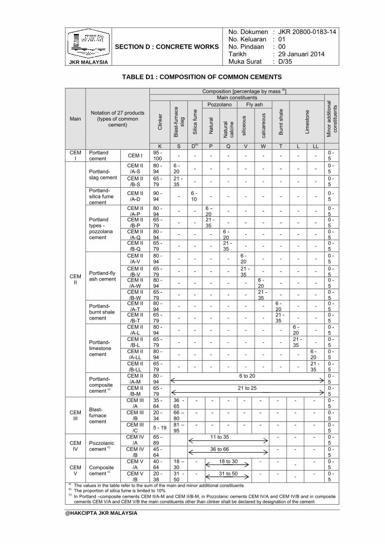
JKR MALAYSIA
SECTION D : CONCRETE WORKS
No. DokumenNo. KeluaranNo. PindaanTarikhMuka Surat
: : : : :
JKR 20800-0183-1401 00 29 Januari 2014 D/35
@HAKCIPTA JKR MALAYSIA
TABLE D1 : COMPOSITION OF COMMON CEMENTS
Main Notation of 27 products
(types of common cement)
Composition [percentage by mass a)] Main constituents
Min
or a
dditi
onal
co
nstit
uent
s
Clin
ker
Bla
st-f
urna
ce
slag
Sili
ca f
ume
Pozzolano Fly ash
Bur
nt s
hale
Lim
esto
ne
Nat
ural
Nat
ural
ca
lcin
e
silic
eous
calc
areo
us
K S Db) P Q V W T L LL CEM
I Portland cement
CEM I 95 -100
- - - - - - - - - 0 - 5
CEM II
Portland- slag cement
CEM II /A-S
80 - 94
6 - 20
- - - - - - - - 0 - 5
CEM II /B-S
65 - 79
21 - 35
- - - - - - - - 0 - 5
Portland-silica fume cement
CEM II /A-D
90 - 94
- 6 - 10
- - - - - - - 0 - 5
Portland types -pozzolana cement
CEM II /A-P
80 - 94
- - 6 – 20
- - - - - - 0 - 5
CEM II /B-P
65 - 79
- - 21 - 35
- - - - - - 0 - 5
CEM II /A-Q
80 - 94
- - - 6 - 20
- - - - - 0 - 5
CEM II /B-Q
65 - 79
- - - 21 - 35
- - - - - 0 - 5
Portland-fly ash cement
CEM II /A-V
80 - 94
- - - - 6 - 20
- - - - 0 - 5
CEM II /B-V
65 - 79
- - - - 21 - 35
- - - - 0 - 5
CEM II /A-W
80 - 94
- - - - - 6 - 20
- - - 0 - 5
CEM II /B-W
65 - 79
- - - - - 21 - 35
- - - 0 - 5
Portland- burnt shale cement
CEM II /A-T
80 - 94
- - - - - - 6 - 20
- - 0 - 5
CEM II /B-T
65 - 79
- - - - - - 21 - 35
- - 0 - 5
Portland-limestone cement
CEM II /A-L
80 - 94
- - - - - - - 6 - 20
- 0 - 5
CEM II /B-L
65 - 79
- - - - - - - 21 - 35
- 0 - 5
CEM II /A-LL
80 -94
- - - - - - - - 6 - 20
0 - 5
CEM II /B-LL
65 - 79
- - - - - - - - 21 - 35
0 - 5
Portland-composite cement c)
CEM II /A-M
80 -94
6 to 20 0 - 5
CEM II /B-M
65 - 79
21 to 25 0 - 5
CEM III
Blast-furnace cement
CEM III /A
35 - 64
36 - 65
- - - - - - - - 0 - 5
CEM III /B
20 -34
66 – 80
- - - - - - - - 0 - 5
CEM III /C
5 - 19 81 – 95
- - - - - - - - 0 - 5
CEM IV
Pozzolanic cement c)
CEM IV /A
65 - 89
11 to 35 - - - 0 - 5
CEM IV /B
45 - 64
36 to 66 - - - 0 - 5
CEM V
Composite cement c)
CEM V /A
40 - 64
18 – 30
- 18 to 30 - - -
- 0 - 5
CEM V /B
20 - 38
31 - 50
- 31 to 50 - - -
- 0 - 5
a) The values in the table refer to the sum of the main and minor additional constituentsb) The proportion of silica fume is limited to 10%
c) In Portland –composite cements CEM II/A-M and CEM II/B-M, in Pozzolanic cements CEM IV/A and CEM IV/B and in composite cements CEM V/A and CEM V/B the main constituents other than clinker shall be declared by designation of the cement
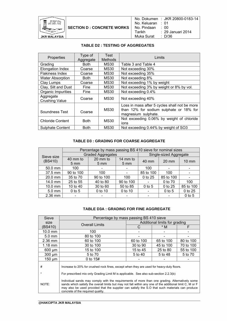
JKR MALAYSIA
SECTION D : CONCRETE WORKS
No. DokumenNo. KeluaranNo. PindaanTarikhMuka Surat
: : : : :
JKR 20800-0183-1401 00 29 Januari 2014 D/36
@HAKCIPTA JKR MALAYSIA
TABLE D2 : TESTING OF AGGREGATES
Properties Type of
Aggregate Test
Methods Limits
Grading Both MS30 Table 3 and Table 4 Elongation Index Coarse MS30 Not exceeding 30% Flakiness Index Coarse MS30 Not exceeding 35% Water Absorption Both MS30 Not exceeding 8% Clay Lumps Coarse MS30 Not exceeding 1% by weight Clay, Silt and Dust Fine MS30 Not exceeding 3% by weight or 8% by vol. Organic Impurities Fine MS30 Not exceeding 0.4% Aggregate Crushing Value
Coarse MS30 Not exceeding 40%
Soundness Test
Coarse
MS30
Loss in mass after 5 cycles shall not be more than 12% for sodium sulphate or 18% for magnesium sulphate.
Chloride Content Both MS30 Not exceeding 0.06% by weight of chloride ions
Sulphate Content Both MS30 Not exceeding 0.44% by weight of SO3
TABLE D3 : GRADING FOR COARSE AGGREGATE
Sieve size (BS410)
Percentage by mass passing BS 410 sieve for nominal sizes Graded Aggregates Single-sized Aggregate
40 mm to 5 mm
20 mm to 5 mm
14 mm to 5 mm
40 mm 20 mm 10 mm
50.0 mm 100 - - 100 - - 37.5 mm 90 to 100 100 - 85 to 100 100 - 20.0 mm 35 to 70 90 to 100 100 0 to 25 85 to 100 - 14.0 mm 25 to 55 40 to 80 90 to 100 - 0 to 70 100 10.0 mm 10 to 40 30 to 60 50 to 85 0 to 5 0 to 25 85 to 100 5.0 mm 0 to 5 0 to 10 0 to 10 - 0 to 5 0 to 25
2.36 mm - - - - - 0 to 5
TABLE D3A : GRADING FOR FINE AGGREGATE
Sieve size
(BS410)
Percentage by mass passing BS 410 sieve
Overall Limits Additional limits for grading
C * M F 10.0 mm 100 - - - 5.0 mm 80 to 100 - - -
2.36 mm 60 to 100 60 to 100 65 to 100 80 to 100 1.18 mm 30 to 100 30 to 90 45 to 100 70 to 100 600 μm 15 to 100 15 to 45 25 to 80 55 to 100 300 μm 5 to 70 5 to 40 5 to 48 5 to 70 150 μm 0 to 15# - - -
# * NOTE:
Increase to 20% for crushed rock fines, except when they are used for heavy-duty floors. For prescribed mix only Grading Limit M is applicable. See also sub-section 2.2.3(b) Individual sands may comply with the requirements of more than one grading. Alternatively some sands which satisfy the overall limits but may not fall within any one of the additional limit C, M or F may also be used provided that the supplier can satisfy the S.O that such materials can produce concrete of the required quality.
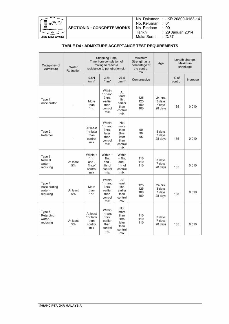
JKR MALAYSIA
SECTION D : CONCRETE WORKS
No. DokumenNo. KeluaranNo. PindaanTarikhMuka Surat
: : : : :
JKR 20800-0183-1401 00 29 Januari 2014 D/37
@HAKCIPTA JKR MALAYSIA
TABLE D4 : ADMIXTURE ACCEPTANCE TEST REQUIREMENTS
Categories of Admixture
Water Reduction
Stiffening Time Time from completion of
mixing to reach a resistance to penetration of:-
Minimum
Strength as a percentage of
the control mix
Age Length change,
Maximum shrinkage
0.5N /mm²
3.5N /mm²
27.5 /mm²
Compressive % of
control Increase
Type 1: Accelerator
-
More than 1hr.
Within
1hr.and 3hrs.
earlier than
control mix
At
least 1hr.
earlier than
control mix
125 125 100 100
24 hrs. 3 days 7 days
28 days
135
0.010
Type 2: Retarder
-
At least 1hr.later
than control
mix
Within
1hr.and 3hrs. later than
control mix
Not
more than 3hrs. later than
control mix
90 90 95
3 days 7 days
28 days
135
0.010
Type 3: Normal water- reducing
At least
5%
Within +
1hr. and - 1hr.of control
mix
Within +
1hr. and - 1hr.of control
mix
Within + 1hr. and - 1hr.of control
mix
110 110 110
3 days 7 days
28 days
135
0.010
Type 4: Accelerating water- reducing
At least 5%
More than 1hr.
Within
1hr.and 3hrs.
earlier than
control mix
At
least 1hr.
earlier than
control mix
125 125 100 100
24 hrs. 3 days 7 days
28 days
135
0.010
Type 5: Retarding water- reducing
At least 5%
At least 1hr.later
than control
mix
Within
1hr.and 3hrs.
earlier than
control mix
Not
more than 3hrs. later than
control mix
110 110 110
3 days 7 days
28 days
135
0.010
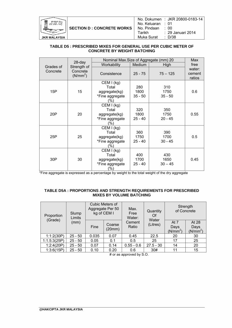
JKR MALAYSIA
SECTION D : CONCRETE WORKS
No. DokumenNo. KeluaranNo. PindaanTarikhMuka Surat
: : : : :
JKR 20800-0183-1401 00 29 Januari 2014 D/38
@HAKCIPTA JKR MALAYSIA
TABLE D5 : PRESCRIBED MIXES FOR GENERAL USE PER CUBIC METER OF CONCRETE BY WEIGHT BATCHING
Grades of Concrete
28-day Strength of Concrete (N/mm2)
Nominal Max.Size of Aggregate (mm) 20 Max free
water: cement ratios
Workability Medium High
Consistence 25 - 75 75 – 125
15P 15
CEM I (kg) Total
aggregate(kg) *Fine aggregate
(%)
280 1800
35 - 50
310 1750
35 - 50 0.6
20P 20
CEM I (kg) Total
aggregate(kg) *Fine aggregate
(%)
320 1800
25 - 40
350 1750
20 - 45 0.55
25P 25
CEM I (kg) Total
aggregate(kg) *Fine aggregate
(%)
360 1750
25 - 40
390 1700
30 - 45 0.5
30P 30
CEM I (kg) Total
aggregate(kg) *Fine aggregate
(%)
400 1700
25 - 40
430 1650
30 – 45 0.45
*Fine aggregate is expressed as a percentage by weight to the total weight of the dry aggregate
TABLE D5A : PROPORTIONS AND STRENGTH REQUIREMENTS FOR PRESCRIBED MIXES BY VOLUME BATCHING
Proportion (Grade)
Slump Limits (mm)
Cubic Meters of Aggregate Per 50
kg of CEM I
Max. Free
Water: Cement
Ratio
Quantity Of
Water (Litres)
Strength of Concrete
Fine Coarse (20mm)
At 7 Days
(N/mm2)
At 28 Days
(N/mm2) 1:1:2(30P) 25 - 50 0.035 0.07 0.45 22.5 20 30
1:1.5:3(25P) 25 - 50 0.05 0.1 0.5 25 17 25 1:2:4(20P) 25 - 50 0.07 0.14 0.55 - 0.6 27.5 - 30 14 20 1:3:6(15P) 25 - 50 0.10 0.20 0.6 30# 11 15
# or as approved by S.O.
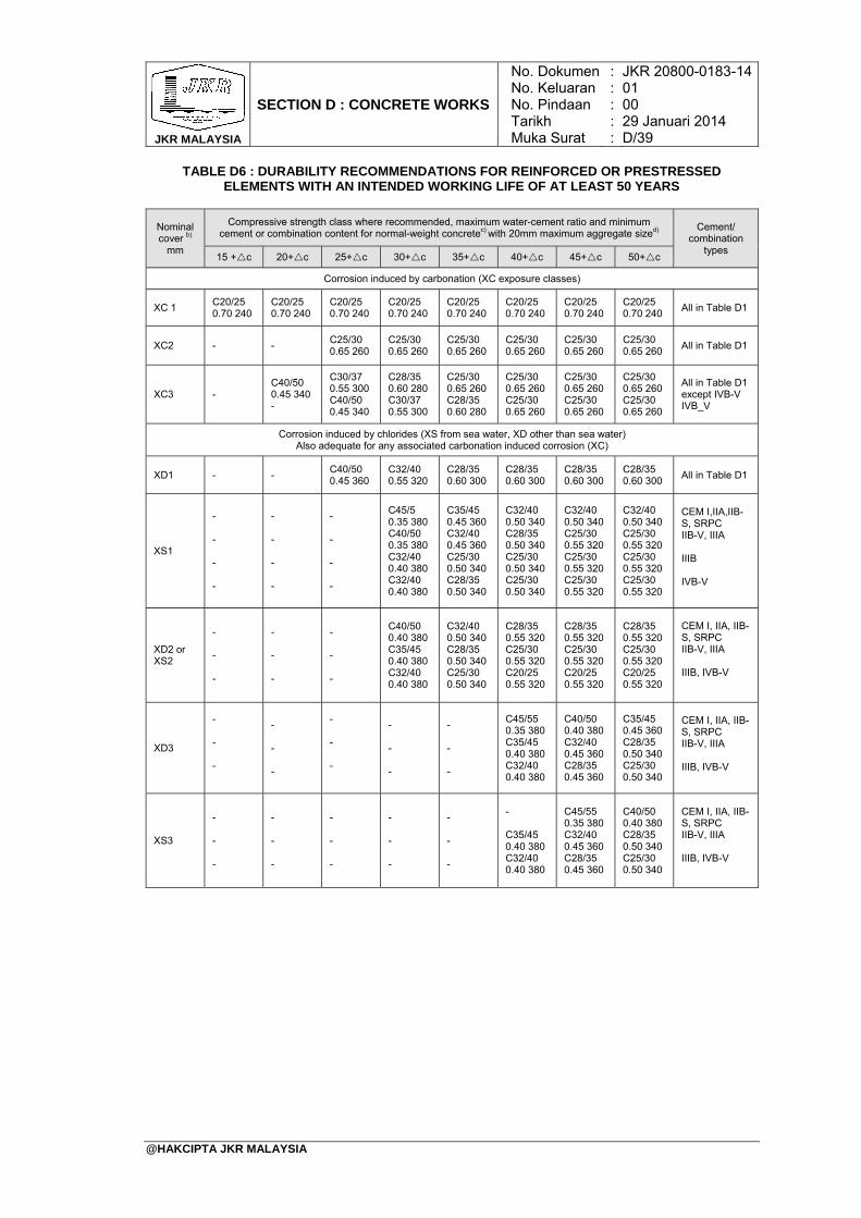
JKR MALAYSIA
SECTION D : CONCRETE WORKS
No. DokumenNo. KeluaranNo. PindaanTarikhMuka Surat
: : : : :
JKR 20800-0183-1401 00 29 Januari 2014 D/39
@HAKCIPTA JKR MALAYSIA
TABLE D6 : DURABILITY RECOMMENDATIONS FOR REINFORCED OR PRESTRESSED ELEMENTS WITH AN INTENDED WORKING LIFE OF AT LEAST 50 YEARS
Nominal cover b)
mm
Compressive strength class where recommended, maximum water-cement ratio and minimum cement or combination content for normal-weight concretec) with 20mm maximum aggregate sized)
Cement/ combination
types 15 +c 20+c 25+c 30+c 35+c 40+c 45+c 50+c
Corrosion induced by carbonation (XC exposure classes)
XC 1 C20/25 0.70 240
C20/25 0.70 240
C20/25 0.70 240
C20/25 0.70 240
C20/25 0.70 240
C20/25 0.70 240
C20/25 0.70 240
C20/25 0.70 240
All in Table D1
XC2 - - C25/30 0.65 260
C25/30 0.65 260
C25/30 0.65 260
C25/30 0.65 260
C25/30 0.65 260
C25/30 0.65 260
All in Table D1
XC3 - C40/50 0.45 340 -
C30/37 0.55 300 C40/50 0.45 340
C28/35 0.60 280 C30/37 0.55 300
C25/30 0.65 260 C28/35 0.60 280
C25/30 0.65 260 C25/30 0.65 260
C25/30 0.65 260 C25/30 0.65 260
C25/30 0.65 260 C25/30 0.65 260
All in Table D1 except IVB-V IVB_V
Corrosion induced by chlorides (XS from sea water, XD other than sea water) Also adequate for any associated carbonation induced corrosion (XC)
XD1 - - C40/50 0.45 360
C32/40 0.55 320
C28/35 0.60 300
C28/35 0.60 300
C28/35 0.60 300
C28/35 0.60 300
All in Table D1
XS1
- - - -
- - - -
- - - -
C45/5
0.35 380 C40/50 0.35 380 C32/40 0.40 380 C32/40 0.40 380
C35/45 0.45 360 C32/40 0.45 360 C25/30 0.50 340 C28/35 0.50 340
C32/40 0.50 340 C28/35 0.50 340 C25/30 0.50 340 C25/30 0.50 340
C32/40 0.50 340 C25/30 0.55 320 C25/30 0.55 320 C25/30 0.55 320
C32/40 0.50 340 C25/30 0.55 320 C25/30 0.55 320 C25/30 0.55 320
CEM I,IIA,IIB-S, SRPC IIB-V, IIIA IIIB IVB-V
XD2 or XS2
- - -
- - -
- - -
C40/50 0.40 380 C35/45 0.40 380 C32/40 0.40 380
C32/40 0.50 340 C28/35 0.50 340 C25/30 0.50 340
C28/35 0.55 320 C25/30 0.55 320 C20/25 0.55 320
C28/35 0.55 320 C25/30 0.55 320 C20/25 0.55 320
C28/35 0.55 320 C25/30 0.55 320 C20/25 0.55 320
CEM I, IIA, IIB-S, SRPC IIB-V, IIIA IIIB, IVB-V
XD3
- - -
- - -
- - -
- - -
- - -
C45/55 0.35 380 C35/45 0.40 380 C32/40 0.40 380
C40/50 0.40 380 C32/40 0.45 360 C28/35 0.45 360
C35/45 0.45 360 C28/35 0.50 340 C25/30 0.50 340
CEM I, IIA, IIB-S, SRPC IIB-V, IIIA IIIB, IVB-V
XS3
- - -
- - -
- - -
- - -
- - -
- C35/45 0.40 380 C32/40 0.40 380
C45/55 0.35 380 C32/40 0.45 360 C28/35 0.45 360
C40/50 0.40 380 C28/35 0.50 340 C25/30 0.50 340
CEM I, IIA, IIB-S, SRPC IIB-V, IIIA IIIB, IVB-V
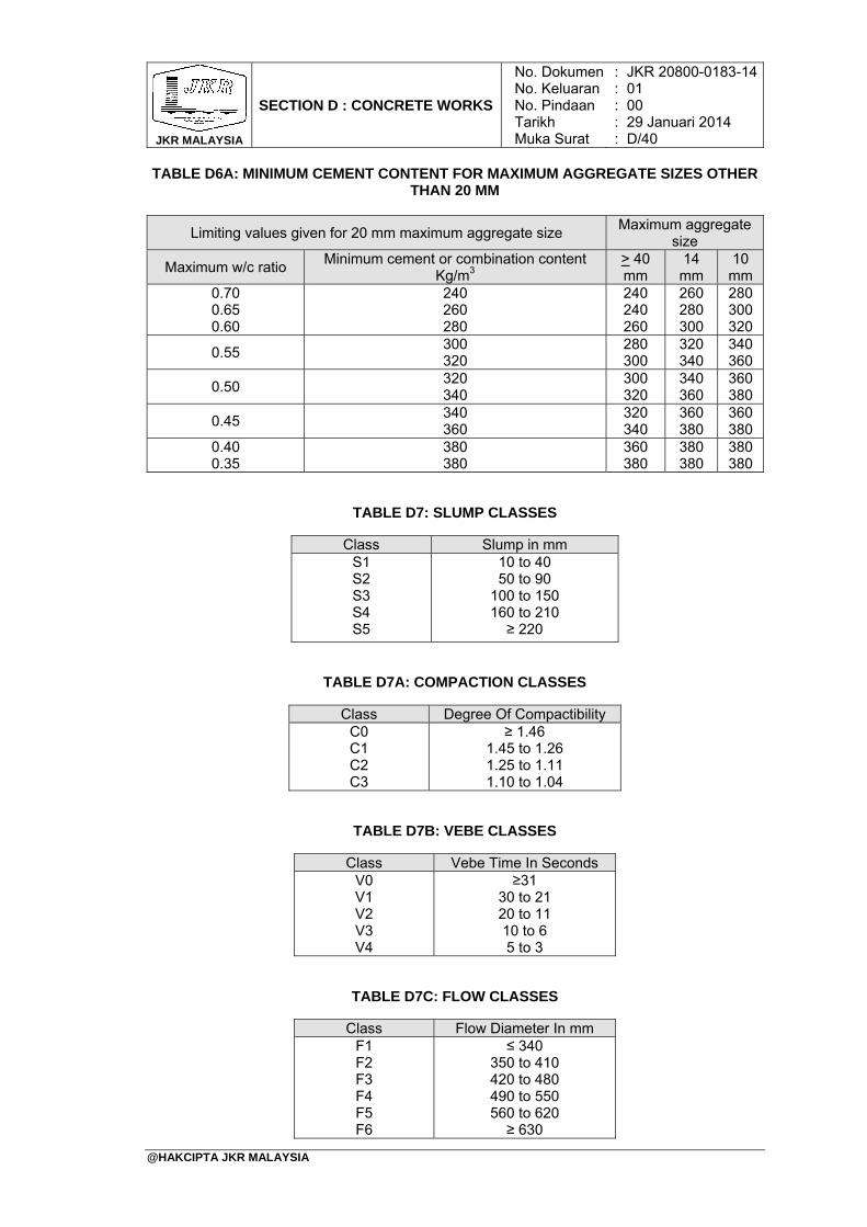
JKR MALAYSIA
SECTION D : CONCRETE WORKS
No. DokumenNo. KeluaranNo. PindaanTarikhMuka Surat
: : : : :
JKR 20800-0183-1401 00 29 Januari 2014 D/40
@HAKCIPTA JKR MALAYSIA
TABLE D6A: MINIMUM CEMENT CONTENT FOR MAXIMUM AGGREGATE SIZES OTHER THAN 20 MM
Limiting values given for 20 mm maximum aggregate size Maximum aggregate
size
Maximum w/c ratio Minimum cement or combination content
Kg/m3 > 40 mm
14 mm
10 mm
0.70 0.65 0.60
240 260 280
240 240 260
260 280 300
280 300 320
0.55 300 320
280 300
320 340
340 360
0.50 320 340
300 320
340 360
360 380
0.45 340 360
320 340
360 380
360 380
0.40 0.35
380 380
360 380
380 380
380 380
TABLE D7: SLUMP CLASSES
Class Slump in mm S1 S2 S3 S4 S5
10 to 40 50 to 90
100 to 150 160 to 210 ≥ 220
TABLE D7A: COMPACTION CLASSES
Class Degree Of Compactibility C0 C1 C2 C3
≥ 1.46 1.45 to 1.26 1.25 to 1.11 1.10 to 1.04
TABLE D7B: VEBE CLASSES
Class Vebe Time In Seconds V0 V1 V2 V3 V4
≥31 30 to 21 20 to 11 10 to 6 5 to 3
TABLE D7C: FLOW CLASSES
Class Flow Diameter In mm F1 F2 F3 F4 F5 F6
≤ 340 350 to 410 420 to 480 490 to 550 560 to 620 ≥ 630
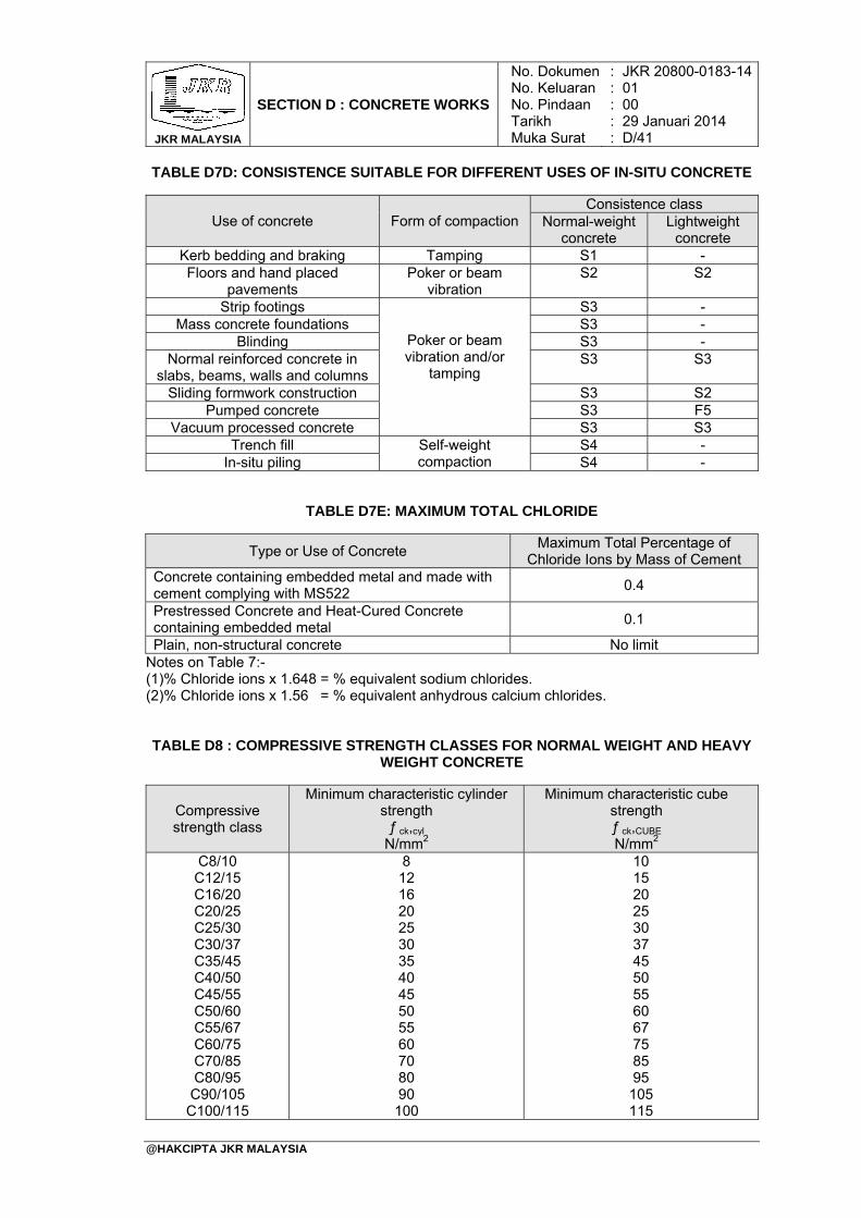
JKR MALAYSIA
SECTION D : CONCRETE WORKS
No. DokumenNo. KeluaranNo. PindaanTarikhMuka Surat
: : : : :
JKR 20800-0183-1401 00 29 Januari 2014 D/41
@HAKCIPTA JKR MALAYSIA
TABLE D7D: CONSISTENCE SUITABLE FOR DIFFERENT USES OF IN-SITU CONCRETE
Use of concrete Form of compaction Consistence class
Normal-weight concrete
Lightweight concrete
Kerb bedding and braking Tamping S1 - Floors and hand placed
pavements Poker or beam
vibration S2 S2
Strip footings
Poker or beam vibration and/or
tamping
S3 - Mass concrete foundations S3 -
Blinding S3 - Normal reinforced concrete in
slabs, beams, walls and columns S3 S3
Sliding formwork construction S3 S2 Pumped concrete S3 F5
Vacuum processed concrete S3 S3 Trench fill Self-weight
compaction S4 -
In-situ piling S4 -
TABLE D7E: MAXIMUM TOTAL CHLORIDE
Type or Use of Concrete Maximum Total Percentage of
Chloride Ions by Mass of Cement Concrete containing embedded metal and made with cement complying with MS522
0.4
Prestressed Concrete and Heat-Cured Concrete containing embedded metal
0.1
Plain, non-structural concrete No limit Notes on Table 7:- (1)% Chloride ions x 1.648 = % equivalent sodium chlorides. (2)% Chloride ions x 1.56 = % equivalent anhydrous calcium chlorides. TABLE D8 : COMPRESSIVE STRENGTH CLASSES FOR NORMAL WEIGHT AND HEAVY
WEIGHT CONCRETE
Compressive strength class
Minimum characteristic cylinder strength
ƒ ck,cyl N/mm2
Minimum characteristic cube strength ƒ ck,CUBE
N/mm2 C8/10 C12/15 C16/20 C20/25 C25/30 C30/37 C35/45 C40/50 C45/55 C50/60 C55/67 C60/75 C70/85 C80/95 C90/105
C100/115
8 12 16 20 25 30 35 40 45 50 55 60 70 80 90 100
10 15 20 25 30 37 45 50 55 60 67 75 85 95 105 115
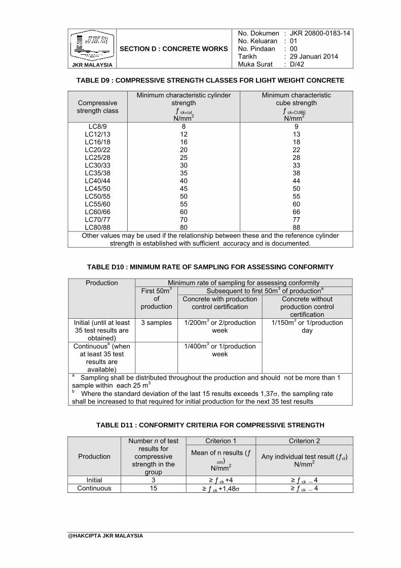
JKR MALAYSIA
SECTION D : CONCRETE WORKS
No. DokumenNo. KeluaranNo. PindaanTarikhMuka Surat
: : : : :
JKR 20800-0183-1401 00 29 Januari 2014 D/42
@HAKCIPTA JKR MALAYSIA
TABLE D9 : COMPRESSIVE STRENGTH CLASSES FOR LIGHT WEIGHT CONCRETE
Compressive strength class
Minimum characteristic cylinder strength
ƒ ck,cyl
N/mm2
Minimum characteristic cube strength
ƒ ck,CUBE
N/mm2 LC8/9
LC12/13 LC16/18 LC20/22 LC25/28 LC30/33 LC35/38 LC40/44 LC45/50 LC50/55 LC55/60 LC60/66 LC70/77 LC80/88
8 12 16 20 25 30 35 40 45 50 55 60 70 80
9 13 18 22 28 33 38 44 50 55 60 66 77 88
Other values may be used if the relationship between these and the reference cylinder strength is established with sufficient accuracy and is documented.
TABLE D10 : MINIMUM RATE OF SAMPLING FOR ASSESSING CONFORMITY
Production Minimum rate of sampling for assessing conformity First 50m3
of production
Subsequent to first 50m3 of productiona Concrete with production
control certification Concrete without production control
certification Initial (until at least 35 test results are
obtained)
3 samples 1/200m3 or 2/production week
1/150m3 or 1/production day
Continuousb (when at least 35 test
results are available)
1/400m3 or 1/production week
a Sampling shall be distributed throughout the production and should not be more than 1 sample within each 25 m3
b Where the standard deviation of the last 15 results exceeds 1,37, the sampling rate shall be increased to that required for initial production for the next 35 test results
TABLE D11 : CONFORMITY CRITERIA FOR COMPRESSIVE STRENGTH
Production
Number n of test results for
compressive strength in the
group
Criterion 1 Criterion 2
Mean of n results (ƒ
cm) N/mm2
Any individual test result (ƒcl) N/mm2
Initial 3 ≥ ƒ ck +4 ≥ ƒ ck ― 4 Continuous 15 ≥ ƒ ck +1,48 ≥ ƒ ck ― 4
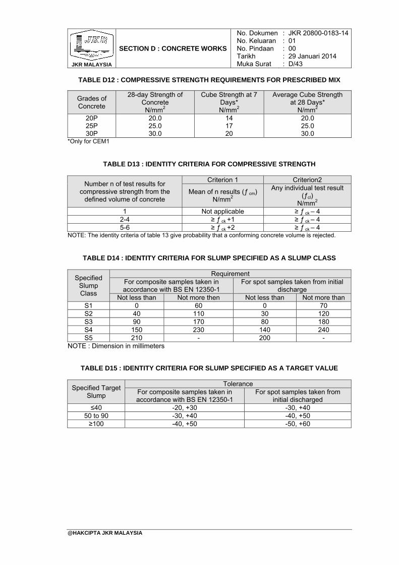
JKR MALAYSIA
SECTION D : CONCRETE WORKS
No. DokumenNo. KeluaranNo. PindaanTarikhMuka Surat
: : : : :
JKR 20800-0183-1401 00 29 Januari 2014 D/43
@HAKCIPTA JKR MALAYSIA
TABLE D12 : COMPRESSIVE STRENGTH REQUIREMENTS FOR PRESCRIBED MIX
Grades of Concrete
28-day Strength of Concrete N/mm2
Cube Strength at 7 Days* N/mm2
Average Cube Strength at 28 Days*
N/mm2 20P 25P 30P
20.0 25.0 30.0
14 17 20
20.0 25.0 30.0
*Only for CEM1
TABLE D13 : IDENTITY CRITERIA FOR COMPRESSIVE STRENGTH
Number n of test results for compressive strength from the
defined volume of concrete
Criterion 1 Criterion2
Mean of n results (ƒ cm) N/mm2
Any individual test result (ƒcl)
N/mm2 1 Not applicable ≥ ƒ ck – 4
2-4 ≥ ƒ ck +1 ≥ ƒ ck – 4 5-6 ≥ ƒ ck +2 ≥ ƒ ck – 4
NOTE: The identity criteria of table 13 give probability that a conforming concrete volume is rejected.
TABLE D14 : IDENTITY CRITERIA FOR SLUMP SPECIFIED AS A SLUMP CLASS
Specified Slump Class
Requirement For composite samples taken in accordance with BS EN 12350-1
For spot samples taken from initial discharge
Not less than Not more then Not less than Not more than S1 0 60 0 70 S2 40 110 30 120 S3 90 170 80 180 S4 150 230 140 240 S5 210 - 200 -
NOTE : Dimension in millimeters
TABLE D15 : IDENTITY CRITERIA FOR SLUMP SPECIFIED AS A TARGET VALUE
Specified Target Slump
Tolerance For composite samples taken in accordance with BS EN 12350-1
For spot samples taken from initial discharged
≤40 -20, +30 -30, +40 50 to 90 -30, +40 -40, +50 ≥100 -40, +50 -50, +60
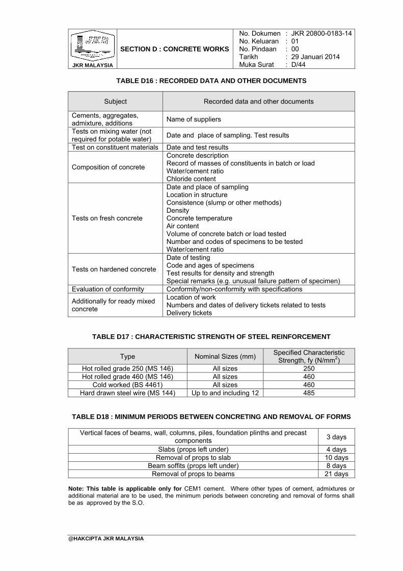
JKR MALAYSIA
SECTION D : CONCRETE WORKS
No. DokumenNo. KeluaranNo. PindaanTarikhMuka Surat
: : : : :
JKR 20800-0183-1401 00 29 Januari 2014 D/44
@HAKCIPTA JKR MALAYSIA
TABLE D16 : RECORDED DATA AND OTHER DOCUMENTS
Subject Recorded data and other documents
Cements, aggregates, admixture, additions
Name of suppliers
Tests on mixing water (not required for potable water)
Date and place of sampling. Test results
Test on constituent materials Date and test results
Composition of concrete
Concrete description Record of masses of constituents in batch or load Water/cement ratio Chloride content
Tests on fresh concrete
Date and place of sampling Location in structure Consistence (slump or other methods) Density Concrete temperature Air content Volume of concrete batch or load tested Number and codes of specimens to be tested Water/cement ratio
Tests on hardened concrete
Date of testing Code and ages of specimens Test results for density and strength Special remarks (e.g. unusual failure pattern of specimen)
Evaluation of conformity Conformity/non-conformity with specifications
Additionally for ready mixed concrete
Location of work Numbers and dates of delivery tickets related to tests Delivery tickets
TABLE D17 : CHARACTERISTIC STRENGTH OF STEEL REINFORCEMENT
Type Nominal Sizes (mm) Specified Characteristic
Strength, fy (N/mm2) Hot rolled grade 250 (MS 146) All sizes 250 Hot rolled grade 460 (MS 146) All sizes 460
Cold worked (BS 4461) All sizes 460 Hard drawn steel wire (MS 144) Up to and including 12 485
TABLE D18 : MINIMUM PERIODS BETWEEN CONCRETING AND REMOVAL OF FORMS
Vertical faces of beams, wall, columns, piles, foundation plinths and precast components
Slabs (props left under)
3 days
4 days Removal of props to slab 10 days
Beam soffits (props left under) 8 days Removal of props to beams 21 days
Note: This table is applicable only for CEM1 cement. Where other types of cement, admixtures or additional material are to be used, the minimum periods between concreting and removal of forms shall be as approved by the S.O.

TABLE OF CONTENTS
SECTION E : NON-STRUCTURAL WALL SYSTEM
PAGE
@HAKCIPTA JKR MALAYSIA
1. General 2. Bricks and Blocks 3. Walling
E/1 E/3 E/4

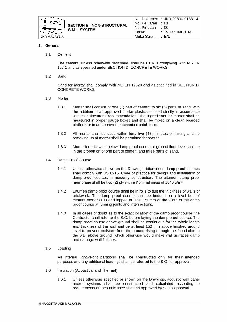
JKR MALAYSIA
SECTION E : NON-STRUCTURAL WALL SYSTEM
No. DokumenNo. KeluaranNo. PindaanTarikhMuka Surat
: : : : :
JKR 20800-0183-1401 00 29 Januari 2014 E/1
@HAKCIPTA JKR MALAYSIA
1. General 1.1 Cement
The cement, unless otherwise described, shall be CEM 1 complying with MS EN 197-1 and as specified under SECTION D: CONCRETE WORKS.
1.2 Sand
Sand for mortar shall comply with MS EN 12620 and as specified in SECTION D: CONCRETE WORKS.
1.3 Mortar
1.3.1 Mortar shall consist of one (1) part of cement to six (6) parts of sand, with
the addition of an approved mortar plasticizer used strictly in accordance with manufacturer’s recommendation. The ingredients for mortar shall be measured in proper gauge boxes and shall be mixed on a clean boarded platform or in an approved mechanical batch mixer.
1.3.2 All mortar shall be used within forty five (45) minutes of mixing and no remaking up of mortar shall be permitted thereafter.
1.3.3 Mortar for brickwork below damp proof course or ground floor level shall be
in the proportion of one part of cement and three parts of sand.
1.4 Damp Proof Course 1.4.1 Unless otherwise shown on the Drawings, bituminous damp proof courses
shall comply with BS 8215: Code of practice for design and installation of damp-proof courses in masonry construction. The bitumen damp proof membrane shall be two (2) ply with a nominal mass of 1840 g/m².
1.4.2 Bitumen damp proof course shall be in rolls to suit the thickness of walls or brickwork. The damp proof course shall be bedded on a level bed of cement mortar (1:1) and lapped at least 150mm or the width of the damp proof course at running joints and intersections.
1.4.3 In all cases of doubt as to the exact location of the damp proof course, the
Contractor shall refer to the S.O. before laying the damp proof course. The damp proof course above ground shall be continuous for the whole length and thickness of the wall and be at least 150 mm above finished ground level to prevent moisture from the ground rising through the foundation to the wall above ground, which otherwise would make wall surfaces damp and damage wall finishes.
1.5 Loading
All internal lightweight partitions shall be constructed only for their intended purposes and any additional loadings shall be referred to the S.O. for approval.
1.6 Insulation (Acoustical and Thermal)
1.6.1 Unless otherwise specified or shown on the Drawings, acoustic wall panel
and/or systems shall be constructed and calculated according to requirements of acoustic specialist and approved by S.O.'s approval.
JKR MALAYSIA
SECTION E : NON-STRUCTURAL WALL SYSTEM
No. DokumenNo. KeluaranNo. PindaanTarikhMuka Surat
: : : : :
JKR 20800-0183-1401 00 29 Januari 2014 E/2
@HAKCIPTA JKR MALAYSIA
1.6.2 Thermal insulation system shall comply with MS1020. Samples of the insulation material shall be submitted to the S.O for approval before they are used and subsequent delivery shall be up to the standard of samples approved.
1.6.3 Unless otherwise shown in the Drawings, glass wool insulation shall be 50mm thick. It shall have a conductive value of maximum 0.035 W/m²K (tested at a mean temperature of 20°C based MS1020 tested according to ASTM C177/C518). Glass wool insulation shall be fixed in accordance with the manufacturer’s recommendation and to the approval of the S.O.
1.6.4 Where stone wool insulation is to be used, it shall be 50mm thick. It shall have a conductive value of maximum 0.035 W/m²K (tested at a mean temperature of 20°C based MS1020 tested according to ASTM C177/C518). Stone wool insulation shall be fixed in accordance with the manufacturer’s recommendation and to the approval of the S.O.
1.6.5 Use of foam based insulation shall be prohibited due to health hazard.
Foam based insulation release toxic substances when heated and burned.
1.7 Fire Rating 1.7.1 Unless otherwise specified or shown on the Drawings, fire rated walls and
partitions system shall be constructed and calculated according to requirements and approval of the DGFR and compliance to the Uniform Building By-Law (UBBL).
1.7.2 The glass wool and stone wool insulation materials used shall comply with BS 476 - Fire tests on building materials and structures:
(i) Non-combustibility test for materials (ii) Method of test for fire propagation for products (iii) Method of test to determine the classification of the surface spread of
flame of products
1.8 Type Of Finishes To Walls And Partitions 1.8.1 Unless otherwise shown in the Drawings, all plastering works for brick
walls shall include the wall surface area above ceiling finish level.
1.8.2 Unless otherwise specified or shown on the drawings, the appropriate type of finishes for walls and partitions shall be as specified in the Schedule of Finishes. Unless otherwise shown on the Drawings or described in the B.Q., The finishes and their dimensions shall be as specified in SECTION K: PLASTERING, PAVING AND TILING WORKS and SECTION O: PAINTING WORKS.
1.9 Samples And Mock-up
1.9.1 Samples and mock-up of wall construction shall be provided and approved
by the S.O. prior to the commencement of the actual construction works. The size of the samples shall be determined by the S.O.
1.9.2 The samples and mock-up for walls and partitions shall include connections between the following components where applicable: (i) Floor to floor to a minimum of 5 meter length (ii) Wall corners (iii) Lintels
JKR MALAYSIA
SECTION E : NON-STRUCTURAL WALL SYSTEM
No. DokumenNo. KeluaranNo. PindaanTarikhMuka Surat
: : : : :
JKR 20800-0183-1401 00 29 Januari 2014 E/3
@HAKCIPTA JKR MALAYSIA
(iv) Stiffeners (v) Door and window frames (vi) All other walls between different materials
2. Bricks And Blocks 2.1 General
All brick walls shall have G.I expanded/exmet mesh reinforcement with 750 mm x 5 mm diameter brickwork dowel bar complete with 75 mm right angle bent to hook onto brickwork at every 4th course.
2.2 Samples
Separate samples of each type of bricks and blocks taken at random from the load, shall be submitted to the S.O. for approval before the bricks and blocks are used. All subsequent deliveries shall generally be up to the standard of the samples approved. No soft, broken, twisted or otherwise defective bricks and blocks will be permitted to be used.
2.3 Clay Bricks
All ordinary clay bricks shall be machine-made, wire cut and shall be hard, well burnt, sound, square and clean all in accordance with MS 76.
2.4 Cement Sand Bricks And Hollow Blocks
2.4.1 All cement sand bricks and hollow blocks shall comply with MS 27.
2.4.2 The dimensions of blocks shall comply with MS 1064.
2.4.3 Wherever blocks are used, a modular sized block shall be used and
constructed in accordance with the manufacturer’s standards, requirements and method statements.
2.4.4 The composition of cement sand bricks and hollow blocks shall consist of a
uniform mixture of sand and cement. The sand cement shall be mixed in the ratio of six (6) parts of sand to one (1) part of cement by volume in a mechanical mixer capable of taking one (1) bag of cement (50 kg of cement shall be taken as 0.035 cube). The sand used shall be as described hereinbefore and the maximum size shall pass through a 4.8 mm mesh BS sieve. The cement used shall be CEM 1 as described under SECTION D: CONCRETE WORKS.
2.4.5 The Contractor shall only use cement sand bricks and hollow blocks
supplied by approved manufacturer.
2.4.6 The minimum permissible average compressive strength shall be 5.2 N/mm² for bricks and 2.8 N/mm² for hollow blocks per 10 samples taken at random from the Contractor’s stock pile of 1000 or part thereof. All rejected or condemned bricks shall be removed from site at the Contractor’s expense.
JKR MALAYSIA
SECTION E : NON-STRUCTURAL WALL SYSTEM
No. DokumenNo. KeluaranNo. PindaanTarikhMuka Surat
: : : : :
JKR 20800-0183-1401 00 29 Januari 2014 E/4
@HAKCIPTA JKR MALAYSIA
2.5 Autoclaved Aerated Concrete Block
2.5.1 Autoclaved aerated concrete blocks shall be high pressure steam cured consisting of a mixture of ordinary cement, sand and lime. The mix shall be free from asbestos or toxic substances.
2.5.2 Where autoclaved aerated concrete blocks are used in lieu of clay bricks, a modular sized block shall be used according to manufacturer’s standards, requirements and method statements.
2.5.3 The autoclaved aerated concrete blocks shall have the following
performance criteria:
(i) dry density of between 500 kg/m³ and 700 kg/m³; (ii) dimensional accuracy of ± 1.5 mm on all faces; (iii) the minimum permissible compressive strength shall be 2.5 N/mm²
per 10 samples taken at random from the contractor’s stock pile of 1000 or part thereof;
(iv) minimum fire rating of two (2) hours.
2.6 Patented Brick And Block Patented bricks and blocks shall comply with MS 27 and shall be used and laid strictly in accordance with the manufacturer’s instructions.
2.7 Large Prefabricated Panels.
Large prefabricated panels when used shall conform to MS 1313 and shall be installed strictly in accordance with the manufacturer’s recommendations.
3. Walling 3.1 Brick Walling
3.1.1 Unless otherwise specified or shown on the Drawings, the whole of the
brickwork shall be constructed with standard size clay bricks in mortar as described and the surface left ready for plastering.
3.1.2 All clay bricks shall be soaked in a suitable tank or pit to be provided by the Contractor for at least half an hour before being laid and shall be kept wet whilst being laid. The top of walls left off shall be thoroughly wet before work is resumed. All constructed walling must be left wet and properly protected from the direct sunlight during the following day. The Contractor shall provide sufficient means to ensure that this is done.
3.1.3 Cement sand bricks shall not be soaked but dipped in water before being
laid and all constructed brickwork shall be protected from direct sunlight during the day on which it is laid and also during the following day and the contractor shall provide sufficient means to ensure that this is done.
3.1.4 All bricks shall be properly bedded in mortar and all joints shall be thoroughly flushed up and raked out to a depth of 13 mm as the works proceeds. No joint shall exceed 10 mm in thickness.
3.1.5 Brickwork shall be carried up perfectly true and plumb in a uniform manner.
No one portion being raised more than 1m above another at one time. No overhand work shall be permitted and scaffolding shall be carried up as the
JKR MALAYSIA
SECTION E : NON-STRUCTURAL WALL SYSTEM
No. DokumenNo. KeluaranNo. PindaanTarikhMuka Surat
: : : : :
JKR 20800-0183-1401 00 29 Januari 2014 E/5
@HAKCIPTA JKR MALAYSIA
work proceeds. The vertical points of every alternate course shall be kept perpendicular over one another, and all perpends, quoins, et cetera shall be kept strictly true and square.
3.1.6 All intersections and angles of walls shall be properly bonded together, and
all walls and piers of lengths not multiples of brick sizes shall be cut and bonded in the best approved manner. No broken bricks shall be used except where required to form bonds.
3.1.7 All half brick (113 mm) walls shall be reinforced at every fourth course with
approved reinforcement (for example exmet) commencing two courses above floor level. For block walling, reinforcement shall be at every second course commencing one course above floor level.
3.1.8 All brick walls shall be constructed on reinforced concrete beams in
accordance with the Drawings. No brick walls except lightweight partitions are allowed to be constructed on reinforced concrete slabs.
3.1.9 Unless otherwise specified, all toilet perimeter walls shall be constructed
using clay bricks. Cement sand bricks shall not be used for toilet walls.
3.1.10 All half brick walls shall be built in Stretcher Bond.
3.1.11 All other brickwork shall be built in English Bond or as shown on the Drawings.
3.2 Facing Brickwork
3.2.1 All facing brickwork shall be executed in first quality approved facing bricks
in Stretcher or Flemish Bond as shown on the Drawings, properly bonded into any backing walls, piers, et cetera. Joints shall be racked out to a depth of 13 mm and point up in coloured cement mortar to approved tints, finished with a neat struck weathered joint.
3.2.2 Facing brickwork shall be kept perfectly clean and no rubbing down of brickwork will be allowed.
3.3 Stonework
3.3.1 Unless otherwise shown on the Drawings or described in the B.Q., all stone blocks used shall be of limestone or granite whichever is more readily available within the locality of the Site and shall be free from cracks, fissures or other defects to the approval of the S.O. The stone blocks shall in general, have their largest faces parallel. Unless otherwise required, the maximum thickness of the stone blocks shall in no case exceed the thickness of the wall or portion of the structure into which it is being built.
3.3.2 Stone walling shall be laid random uncoursed or random coursed as shown on the Drawings. Through or bonded stones shall be used at one stone per meter square for random coursed. Where backing brick wall is shown, the through stone shall be properly bonded in such brick wall.
3.3.3 Unless otherwise shown on the Drawings, all stonework shall be bedded in
cement and sand mortar (1:3) mix and finished with a flushed joint rubbed down with sacking. All interstices between individual stones shall be filled with mortar. Finish to exposed surfaces or random walling shall be hammer-dressed.
JKR MALAYSIA
SECTION E : NON-STRUCTURAL WALL SYSTEM
No. DokumenNo. KeluaranNo. PindaanTarikhMuka Surat
: : : : :
JKR 20800-0183-1401 00 29 Januari 2014 E/6
@HAKCIPTA JKR MALAYSIA
3.4 Hollow Block Walling The cement sand block wall shall be laid in the manner specified for brick wall. The hollow block shall not be soaked but dipped in water before laying. The hollow block wall shall be reinforced at every second course with reinforcement commencing one course above floor level.
3.5 Autoclaved Aerated Concrete Block Walling
3.5.1 Where shown on the Drawings and/or described in the B.Q. or as an
alternative to clay bricks, the Contractor may use autoclaved aerated concrete blocks for non-load bearing walls and partitions. The autoclaved aerated concrete block work shall be constructed strictly in accordance with the manufacturer’s recommendations. Any extra cost in connection therewith shall be borne by the Contractor.
3.5.2 The autoclaved aerated concrete block work shall be installed using an approved thin layer of adhesive mortar to all horizontals and perpends. The first course must be made true and level using a normal layer of mortar with thin layer of adhesive to fully seal the perpends. The thin layer of adhesive shall be applied using notched trowel to obtain an even distribution of adhesive to achieve joint thickness of 2 mm to 3 mm.
3.5.3 A damp-proof course slip-joint membrane shall be laid on top of the floor slab or beams before receiving the mortar bedding to allow for differential movement between the blocks and the supporting structure.
3.5.4 The autoclaved aerated concrete block work shall be laid in a manner that
the vertical joint of the lower course shall be staggered at least 100 mm relative to the vertical joint of the overlaying course.
3.5.5 Unless otherwise directed and/or shown, where concrete block walls abut concrete faces, the face shall be flushed.
3.5.6 Control joints should be built into walls at spacing not greater than 8 m
centres, and at locations in accordance with manufacturer’s recommendation.
3.5.7 Care must be taken to keep the walls clean, strictly in accordance with the
manufacturer’s recommendation. Excess adhesive must be removed progressively.
3.5.8 In lieu of cement sand plastering, the wall surfaces may be finished with
suitable surface coating that has the dual properties of being waterproof and water vapour permeable and shall be applied in accordance with the manufacturer’s recommendation.
3.6 Parapet And Freestanding Wall
3.6.1 Any parapet and freestanding wall consisting of 155 mm thick brick wall
including plastering on both sides shall only be constructed to a maximum height of 900 mm.
3.6.2 Where shown on the Drawings, freestanding walls above 900 mm in height shall be constructed as per the engineer’s detail Drawings or to the S.O.’s approval.
JKR MALAYSIA
SECTION E : NON-STRUCTURAL WALL SYSTEM
No. DokumenNo. KeluaranNo. PindaanTarikhMuka Surat
: : : : :
JKR 20800-0183-1401 00 29 Januari 2014 E/7
@HAKCIPTA JKR MALAYSIA
3.6.3 Precast reinforced concrete copings shall be constructed on all external parapet and free standing walls. The reinforced concrete coping shall be laid to fall, complete with 12 mm half round throating.
3.6.4 Freestanding walls more than 3 m length vertically and horizontally shall be
constructed with reinforced concrete stiffeners to engineer's detail and with the S.O’s approval.
3.7 Lintel And Stiffener
3.7.1 Unless otherwise specified or shown on the Drawings, lintels shall be
provided to all openings and to be sized accordingly by the Contractor to the S.O.’s approval.
3.7.2 Reinforced concrete stiffeners shall be constructed at every minimum of 3 m vertically and horizontally to strengthen brick and block wall system construction according to engineer’s detail.
3.8 Fasteners
Unless otherwise shown on the Drawings, fasteners or cramps for frames, metal windows and precast units shall be built in at 1 m centres on the vertical side of the frame. Mild steel cramps shall be 25 mm x 3 mm x 225 mm long for fixing wooden frames, etc. One end of the cramp shall be turned up and screwed to back of the frame and the other end shall be split and fish-tailed for building in. Cramps which are to be fixed to concrete shall be embedded in concrete and built into brickwork as the work proceeds.
3.9 Cutting
All cuttings such as arches, sinks, setbacks, and projections shall be properly formed. Chases and holes through walls and slabs for the passage of pipes, wiring and the like shall be neatly cut or formed. Upon the installation of the services pipes, the chases and holes through walls shall be properly sealed (Fire Stop) to prevent fire spread as required by the DGFR and UBBL. Where plastering works are done on the cuttings, the surface shall be smooth and seamless.
3.10 Timber Framing For Partition
3.10.1 All timber used for the timber stud framings for partition walls shall be as
specified in SECTION H: TIMBER, JOINERY AND IRONMONGERY WORKS.
3.10.2 Wall partition consisting of timber frames shall consist of vertical and horizontal studs. The studs shall consist of approved timber hardwood with a minimum size of 50 mm x 50 mm unless otherwise specified. All horizontal and vertical studs shall be constructed at a maximum spacing of 600 mm centres.
3.10.3 The top most horizontal frame, referred to as the top plate shall be bolted
or nailed to the ceiling and continuously erected using timber or metal stiffener securely fixed to the slab to the S.O's approval. The timber and metal stiffeners shall be spaced at 1200 mm centres maximum.
3.10.4 The lowest horizontal frame, referred to as the bottom plate, shall be
securely fixed using bolts or nails. All fixing to slabs, M12 expansion bolts shall be used at 1200 mm centres maximum with galvanized mild steel
JKR MALAYSIA
SECTION E : NON-STRUCTURAL WALL SYSTEM
No. DokumenNo. KeluaranNo. PindaanTarikhMuka Surat
: : : : :
JKR 20800-0183-1401 00 29 Januari 2014 E/8
@HAKCIPTA JKR MALAYSIA
strap to the floor to the S.O.'s approval. All fixings to timber slabs shall be fixed at 600 mm centres maximum.
3.10.5 Unless otherwise specified, dimension for timber panels shall comply with
MS 1064.
3.10.6 Where proprietary timber partitions are used, they shall be constructed in accordance with the manufacturer’s recommendations and to the S.O.’s approval.
3.10.7 Partitions, screens and vent panels, shall be constructed as detailed in the
Drawings. Where shown, galvanized welded wire mesh or expanded metal of the required sizes and patterns shall be fixed to vent panels and window openings. The mesh shall be secured in position using rebated and mitred timber battens and screws.
3.11 Metal Framing For Partition
3.11.1 Steel sections such as, but not limited to metal framing and studs shall comply with ASTM C645, BS EN 14195, BS 7364 or other approved equivalent standards as appropriate, and to the approval of the S.O.
3.11.2 Unless otherwise specified, all metal framing for partitions shall be galvanized steel 62 mm C-Studs (vertical) and 64 mm U-tracks (horizontal) of 0.5 mm base metal thickness. The steel stud shall be manufactured from galvanized mild steel strip, steel grade Z2 with minimum yield strength of 210 N/mm² and zinc coating type Z275 minimum, complying with BS EN 10143.
3.11.3 The stud which is to support a joint shall have a minimum fixing face width
of 32 mm for screw fixing and all other framing members shall not be less than 30 mm. Drywall screws shall be at least 10 mm longer than total thickness of plasterboards on each side of the partition wall. The plasterboards are laid staggered and fixed to the metal frames using drywall screws not exceeding 300 mm centres.
3.11.4 The top most U-frame (horizontal) shall be screwed to the ceiling and
continuously erected using metal stiffener securely fixed to the slab. The metal studs directly supporting plasterboard sheets shall be spaced at 600 mm centres maximum. The bottom U-frame (horizontal) shall be securely fixed to the floor slab using bolts or screws. All fixing to slabs, M12 expansion bolts shall be used at 1200mm centres maximum with galvanized mild steel strap to the floor and to the S.O.'s approval.
3.11.5 Unless otherwise shown on the Drawings, the partitions shall not be
erected more than 3000 mm height. Partitions which are more than 3000 mm height shall be supported by additional structural members, to structural engineer's detail and S.O.’s approval.
3.11.6 Partition above ceiling shall allow for cut out opening for service ducts or
trunks and cable trays. The contractor shall coordinate with all subcontractors on the exact location and size of the openings. Any gaps around any pipe ducts through the partition shall be properly sealed with and approved fire smoke stop system. by the penetration collar protection specialist.
3.11.7 If full height partition has to be terminated below ventilation duct route
parallel to the partitions, the stud of the partition shall be secured to the
JKR MALAYSIA
SECTION E : NON-STRUCTURAL WALL SYSTEM
No. DokumenNo. KeluaranNo. PindaanTarikhMuka Surat
: : : : :
JKR 20800-0183-1401 00 29 Januari 2014 E/9
@HAKCIPTA JKR MALAYSIA
support frame of the duct. In such cases, space between the duct and reinforced concrete soffit need not be sealed up.
3.11.8 The deflection of the metal frame partition system under service condition
shall be controlled by the limit for the calculated deflection of the element chosen for the system and its intended use. The deflection shall not exceed L/240 or L/360 subject to the finishing material attached to the partition. Any system wall partition selected shall be installed strictly according to the manufacturer's specifications and details to the S.O.’s approval.
3.12 Plasterboard Partition 3.12.1 The type of plasterboard used shall comply with BS EN 520. The specified
plasterboard shall carry class ‘O’ approval from DGFR. Unless otherwise specified the plasterboards used for the works shall be 12.5 mm thick with standard length of 3000 mm and shall be free of defects.
3.12.2 The deviations and tolerances shall be in accordance with BS 8212. When required, the deflection under load shall be determined in accordance with BS EN 520.
3.12.3 The appropriate type of sealant shall be used for the required type of
plasterboard. Elastomeric sealants shall be used at the perimeter of the dry lining or partitioning to provide an airtight construction and to the approval of the S.O.
3.12.4 Jointing compound shall be of air drying or setting type, in accordance with
BS EN 13963, and to the approval of the S.O. Jointing compound shall be applied as per manufacturer’s recommendation and S.O.’s approval. The use of any additives to modify any of the properties of compounds shall not be permitted.
3.12.5 Jointing tape for plasterboards shall not be less than 48 mm wide and not
exceeding 60 mm in accordance with ASTM C475 and the approval of the S.O.
3.12.6 Control joints shall be provided for a long continuous run of plasterboard
wall spaced at not more than 9 m apart.
3.12.7 Corner beads shall be provided as reinforcement to permit construction of true, concealed angles with gypsum base and panels.
3.12.8 Provision shall be allowed for the plasterboard partition system to support
surface mounted fixtures by incorporating independent support framing hidden behind or exposed on the partition surface to provide adequate and appropriate support and to the approval of the S.O.
3.12.9 Wherever possible, full length plasterboard sheets shall be used to
eliminate the need for sheet end butt joints. Where possible, joints on opposite sides of framing should be arranged to occur between different framing members.
3.12.10 Plasterboard sheets shall be laid out to minimize butt joints and waste. Butt
joints on adjoining sheets shall be staggered. Butt joints on opposite sides of the wall shall be staggered. The sheet shall be laid so that the vertical joints fall a minimum of 200 mm from the edge of the opening.
JKR MALAYSIA
SECTION E : NON-STRUCTURAL WALL SYSTEM
No. DokumenNo. KeluaranNo. PindaanTarikhMuka Surat
: : : : :
JKR 20800-0183-1401 00 29 Januari 2014 E/10
@HAKCIPTA JKR MALAYSIA
3.12.11 Fire resisting systems comprising of more than one layer of plasterboards, the joints in successive layers should be staggered. In the case of walls sheeted on both sides joints should be staggered on opposite sides of the wall.
3.12.12 Penetrations in the system shall only be allowed if installed in accordance
to manufacturer’s recommendation and tested at the Contractor’s expenses. Penetration shall be strictly carried out in accordance with the requirements of the DGFR and to the recommendationapproval of the S.O.
3.12.13 Fasteners shall have a corrosion-resistant finish and be appropriate for
intended use, also in accordance with BS EN 14566 and BS 8212. The heads of fasteners shall be shaped so that they can be driven slightly below the surface of the plasterboard without punching through the paper liner.
3.12.14 Impact resistance of a partition system including gypsum plasterboard shall
be determined in accordance with ISO 7892 and BS 5234-2.
3.12.15 The Contractor shall submit to the S.O., a manufacturer’s warranty against any defect or damage to the proprietary plasterboard partition system which may arise during the period of five (5) years from the date of Certificate of Practical Completion. Terms of the warranty shall be such as shall be approved by the S.O.
3.13 Glass Partitions
3.13.1 Unless otherwise specified or shown on the Drawing, all fixed glass wall
systems shall be 8 mm thick minimum, erected with stainless steel framing system for sizes up to 1200 mm x 4800 mm maximum installed to manufacturer’s recommendation and to S.O.’s approval. For sizes more than 4800 mm, the panels shall be constructed according to manufacturer’s recommendation and the installation shall be certified by a P.E.
3.13.2 Glass doors shall be installed complete with accessories as recommended by the manufacturer and to the S.O.’s approval.
TABLE OF CONTENTS
SECTION F : SEWERAGE WORKS
PAGE
@HAKCIPTA JKR MALAYSIA
1. General 2. Material 3. Layout 4. Excavation 5. Pipes And Fittings 6. Joint For Sewer Pipes 7. Pipe Laying 8. Bedding, Haunching And Surround 9. Connections 10. Manholes, Inspection Chambers And Valve Chambers 11. Septic Tank And Sewage Treatment System 12. Connections To The Public Sewerage Line 13. Testing For Sewer Pipes Installation 14. Backfilling
APPENDIX F/1: TABLE F1: Parameter Limits For Sewage And
Industrial Effluents
F/1 F/1 F/1 F/1 F/3 F/3 F/3 F/4 F/5 F/5 F/6 F/7 F/7 F/9 F/10

JKR MALAYSIA
SECTION F : SEWERAGE WORKS
No. DokumenNo. KeluaranNo. PindaanTarikhMuka Surat
: : : : :
JKR 20800-0183-1401 00 29 Januari 2014 F/1
@HAKCIPTA JKR MALAYSIA
1. General The work to be done under this section unless otherwise shown or described in the B.Q. shall consist of the supply, delivery, construction and testing of all sewerage works and ancillary works, and all necessary works up to the point of final discharge of the effluent. In the case of discharge into the public sewer or the package sewage treatment plant, the work shall terminate up to and including the last manhole or intercepting trap of the system. This section of the work shall be carried out strictly in accordance with the appropriate by-laws and to the approval of the S.O.
2. Material 2.1 Cement, Sand, Aggregates And Bricks
2.1.1 Cement, sand and aggregates shall be as specified in SECTION D:
CONCRETE WORKS. All bricks used unless otherwise shown in the Drawings or described in the B.Q. shall be clay bricks as specified in SECTION E: NON-STRUCTURAL WALL SYSTEM.
2.2 Sewerage Pipe
2.2.1 The Contractor shall only use sewer pipes from suppliers approved by SPAN and all materials shall be inspected and approved by the S.O. before being installed.
2.2.2 The Contractor shall submit the certificate and test report of sewer pipe to the S.O. for approval.
2.2.3 The Contractor shall make sure the sewer pipe is stored and/or stacked
in such manner to prevent breakage.
3. Layout
The whole sewerage work shall be carried out according to the layout as shown on the Drawings.
4. Excavation 4.1 Generally, all excavation works in this section unless otherwise specified
hereunder shall be as specified in SECTION B : EXCAVATION AND EARTHWORKS.
4.2 The Contractor shall carry out survey work to determine the sewer pipe alignment. Clearance from the building/road shall be 1 m. The pipe alignment shall be approved by the S.O. before the contractor starts the excavation works.
4.3 The trench shall be excavated to the depths intended or as shown on the Drawings
and shall be finished and trimmed to the correct level and grade. Unless indicated otherwise, the bottom of the trench shall be graded so that the pipe invert slopes evenly between the appropriate outlet invert of the preceding manhole and the inlet invert of the next manhole.
4.4 The trench shall be excavated to such width so as to ensure that a minimum
working space of 300 mm will be available on each side of the pipe when properly aligned. At all joints, the trench shall be excavated to give a minimum working space of not less than 300 mm all-round the joint.
JKR MALAYSIA
SECTION F : SEWERAGE WORKS
No. DokumenNo. KeluaranNo. PindaanTarikhMuka Surat
: : : : :
JKR 20800-0183-1401 00 29 Januari 2014 F/2
@HAKCIPTA JKR MALAYSIA
4.5 The sides of all excavation unless otherwise approved by the S.O. shall be cut vertical and where necessary shall be protected against caving in by timbering to the approval of the S.O. If the trench is more than 1.5 m, the contractor shall provide support for the trench to avoid collapse, settlement or movement of the banks.
4.6 The trench excavation shall not advance more than 100 m ahead of the completed backfilled pipeline. Pipe shall be laid in all trenches that have been excavated at the end of each day’s work, unless the Contractor get approval from the S.O. to do otherwise.
4.7 It shall be the responsibility of the Contractor to protect and support all existing water pipes, gas and other conduits crossed by the excavation or work to be performed and to arrange for their temporary removal and subsequent replacement.
4.8 The trench should be excavated precisely to ensure the sewer pipe will be in the centre of the trench. The bottoms of the trenches for all sewers shall be carefully and truly graded, formed and lined according to the grades and dimensions as shown on the Drawings.
4.9 Should the ground be so wet or soft, and does not form a firm base for the pipe, if it is necessary in the opinion of the S.O. then the trench shall be excavated 225 mm below the level intended or shown on the Drawings and then brought to the correct level with good selected earth, quarry dust or sand well rammed into place. Such deepening of pipe trench and filling back shall be treated as a variation under the terms of the Contract. Should the bottom of the trench be inadvertently excavated below the specified level, it shall be brought back at the Contractor's expense to the correct level with good selected earth, quarry dust or sand carefully rammed into place.
4.10 The Contractor shall remove any water which collects in the trenches while sewer pipes are being laid. Water encountered shall be disposed of by the Contractor in a manner satisfactory to the S.O.
4.11 Excess material from the trench excavation shall be located 600 mm (minimum) away from the trench.
4.12 When excavating pipe trenches in roadway or other paved surfaces, the Contractor shall first remove all metal, slabs or bricks forming the existing pavement to the width of the trenches and reinstate to the approval of the S.O. after the trenches have been backfilled. The Contractor must make sure that not more than half of the width of a roadway shall be disrupted at any one time during the sewerage work.
4.13 Generally where rock is encountered in the trench excavation, it shall be removed to the approval of the S.O. Where layer of rock is encountered along the bottom of the excavation, it shall be cut and trimmed to the required level of the trench. All voids formed at the bottom of the trench by the removal of rocks shall be back filled to the required level with Grade 20P concrete or other suitable materials well rammed and compacted all to the approval of the S.O. Uneven surfaces of rocks at the bottom of the excavation due to the trimming shall be levelled and smoothen with sand blinding to the approval of the S.O.
4.14 If the works required pipe jacking, the Contractor shall provide method statement for S.O.’s review and approval.
4.15 The Contractor shall ensure that the work performed is safe and in compliance with Occupational Safety and Health Act (OSHA).
JKR MALAYSIA
SECTION F : SEWERAGE WORKS
No. DokumenNo. KeluaranNo. PindaanTarikhMuka Surat
: : : : :
JKR 20800-0183-1401 00 29 Januari 2014 F/3
@HAKCIPTA JKR MALAYSIA
5. Pipes And Fittings
5.1 Generally, all sewer pipes unless otherwise shown on the Drawings, shall be vitrified clay pipes (VCP) and fittings complying with MS 1061 and SPAN guidelines.
5.2 Sewer pipes used for gravity types of sewer shall be a minimum size of 150 mm for service connection and 225 mm for public sewer complying with Malaysian Sewerage Industry Guideline (MSIG).
6. Joint For Sewer Pipes
6.1 Unless otherwise approved by the S.O., joints of flexible and watertight type shall be used on all sewer pipes. The spigot and socket of each pipe shall be cleaned and lubricated before the running of each joint.
6.2 Couplings shall be made either of the same materials as the pipe or other material to the approval of the S.O. The pipes and coupling shall have accurately machined or molded tapered ends, the internal taper of the couplings matching the external taper of the pipes.
7. Pipe Laying
7.1 All pipes shall be laid in compliance with MS 1228 and in accordance with the sizes, locations, dimensions, grades and other particulars as shown in the Drawings. Each pipe shall be carefully inspected upon arrival at site. Sewer pipes shall be carefully stored. Defective pipes shall be marked and removed from the site forthwith.
7.2 Prior to fixing or laying all pipes and fittings shall again be carefully inspect for damage and only those found to be sound in every aspect shall be fixed or laid. Any pipes, specials, et cetera found to be damaged in any way shall be clearly marked, set aside and removed from the site.
7.3 No pipe shall be laid until the trench has been inspected and approved by the S.O.
7.4 The pipes shall be gently lowered into the trench by means approved by the S.O. No pipes shall be rolled or dropped into the trench. The pipe shall be laid true to alignment as shown in the Drawings or as instructed by the S.O. Interior and exterior of each pipe at the joint shall be thoroughly cleaned before the joint is made. Pipes shall be laid from the downstream end towards the upstream end.
7.5 To prevent the entry of earth and other materials into the pipes, the Contractor shall provide and fix suitable stops for efficiently closing all open ends of pipes in the trench while work is not actually being carried out at such open ends.
7.6 Socketed pipes shall be laid with the sockets laid against the direction of flow. At every position of pipe joints, the bedding shall be recessed sufficiently.
7.7 Where sewer pipes are to be laid on concrete bed, haunched or encased in concrete surrounds, these shall be as shown on the Drawings and as specified hereinafter.
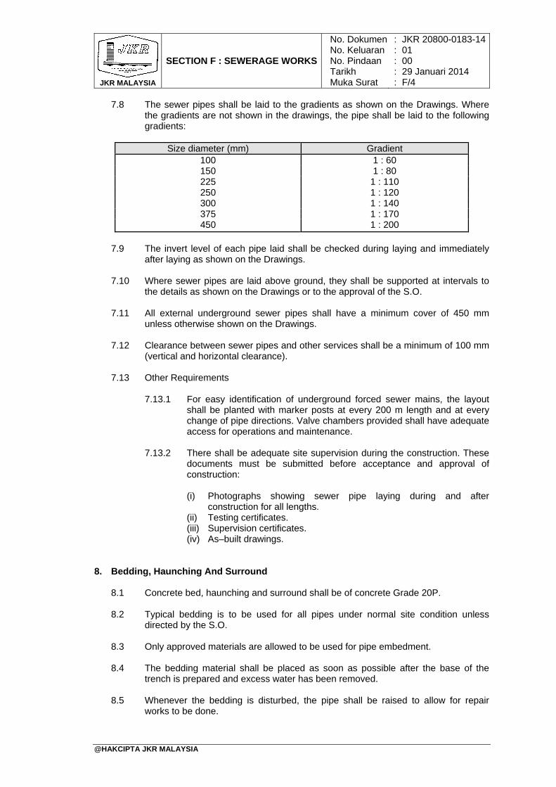
JKR MALAYSIA
SECTION F : SEWERAGE WORKS
No. DokumenNo. KeluaranNo. PindaanTarikhMuka Surat
: : : : :
JKR 20800-0183-1401 00 29 Januari 2014 F/4
@HAKCIPTA JKR MALAYSIA
7.8 The sewer pipes shall be laid to the gradients as shown on the Drawings. Where the gradients are not shown in the drawings, the pipe shall be laid to the following gradients:
Size diameter (mm) Gradient
100 1 : 60 150 1 : 80 225 1 : 110 250 1 : 120 300 1 : 140 375 1 : 170 450 1 : 200
7.9 The invert level of each pipe laid shall be checked during laying and immediately
after laying as shown on the Drawings.
7.10 Where sewer pipes are laid above ground, they shall be supported at intervals to the details as shown on the Drawings or to the approval of the S.O.
7.11 All external underground sewer pipes shall have a minimum cover of 450 mm unless otherwise shown on the Drawings.
7.12 Clearance between sewer pipes and other services shall be a minimum of 100 mm (vertical and horizontal clearance).
7.13 Other Requirements
7.13.1 For easy identification of underground forced sewer mains, the layout
shall be planted with marker posts at every 200 m length and at every change of pipe directions. Valve chambers provided shall have adequate access for operations and maintenance.
7.13.2 There shall be adequate site supervision during the construction. These
documents must be submitted before acceptance and approval of construction:
(i) Photographs showing sewer pipe laying during and after
construction for all lengths. (ii) Testing certificates. (iii) Supervision certificates. (iv) As–built drawings.
8. Bedding, Haunching And Surround
8.1 Concrete bed, haunching and surround shall be of concrete Grade 20P.
8.2 Typical bedding is to be used for all pipes under normal site condition unless directed by the S.O.
8.3 Only approved materials are allowed to be used for pipe embedment.
8.4 The bedding material shall be placed as soon as possible after the base of the trench is prepared and excess water has been removed.
8.5 Whenever the bedding is disturbed, the pipe shall be raised to allow for repair works to be done.
JKR MALAYSIA
SECTION F : SEWERAGE WORKS
No. DokumenNo. KeluaranNo. PindaanTarikhMuka Surat
: : : : :
JKR 20800-0183-1401 00 29 Januari 2014 F/5
@HAKCIPTA JKR MALAYSIA
8.6 Any pegs or other temporary aids for levelling works shall be removed before any pipe being laid.
9. Connections
9.1 The Contractor is to allow and provide for all bends, junctions, traps, gullies as shown on the Drawings or where necessary. If a gully is used, it shall be of the inlet type, and shall be set level on a concrete base, with a riser to finish 50 mm above the surrounding surface level, complete with concrete surrounds rendered on all sides and galvanized iron grating. Bends turned up to receive various stacks shall be set on concrete bases to the approval of the S.O. The bends at the foot of vertical stacks shall be of gentle radius type.
9.2 All underground fittings shall be completely surrounded in concrete and the Contractor shall allow for any additional excavation and jointing of pipes.
10. Manholes, Inspection Chambers And Valve Chambers
10.1 Manholes, inspection chambers and valve chambers shall be constructed with the sizes shown on the Drawings and MSIG guidelines. Unless otherwise shown or specified, all dimensions on the plan shall be the inside measurement.
10.2 Manholes and inspection chambers shall be protected by lining/coating to prevent corrosion of the concrete due to sulphide attack. Internal walls shall be either rendered with sulphate resistant cement mortar at least 20 mm thick or lined with PVC, HDPE or epoxy coating.
10.3 Manholes
10.3.1 Manhole covers and frames 10.3.1.1 Manhole covers and frames shall comply with Drawings and
MSIG guidelines.
10.3.1.2 All surfaces of manhole covers and frames supplied shall be coated as stated in MSIG guidelines with either:
(i) Hot applied bituminous material complying with BS 4147
Type I.
(ii) Cold applied bituminous material complying with BS 3416 Type II.
10.3.2 Manhole testing (before backfilling)
10.3.2.1 Water-tightness test shall be conducted where no visible leakage shall occur between the manhole cover and its seating in the frame when tested in accordance with MSIG guidelines.
10.3.2.2 A visual inspection shall be conducted on all the external and
internal section of each manhole in accordance with MSIG guidelines. Particular attention shall be given to:
(i) The slope of benching. (ii) Joints to pipes. (iii) Transitions at entry and exits.
JKR MALAYSIA
SECTION F : SEWERAGE WORKS
No. DokumenNo. KeluaranNo. PindaanTarikhMuka Surat
: : : : :
JKR 20800-0183-1401 00 29 Januari 2014 F/6
@HAKCIPTA JKR MALAYSIA
(iv) Joints in the structure. (v) Quality of concrete finish. (vi) Water-tightness of manhole covers and surround.
10.4 Inspection Chambers
Unless otherwise as shown on the Drawings, inspection chambers shall be constructed in brickwork in cement mortar (1:2) and the brickwork shall be of clay bricks and constructed on Grade 20P concrete foundation. The thicknesses and sizes shall be as shown on the Drawings. Each inspection chamber shall have channels and open channel junctions of sizes as shown on the Drawings. Concrete benching shall be to a gradient of 1:6 and shall be of Grade 20P concrete finished with 19 mm steel troweled water proofed cement and sand (1:3) rendering. The internal sides of the inspection chambers shall be lined with 20 mm thick PVC, HDPE or epoxy coating. Externally, the exposed concrete or brick surfaces shall be rendered with 12 mm cement and sand mortar (1:3) and terminated 150 mm below the finished ground level. All internal angles shall be rounded off. Inspection chambers shall be provided with covers and unless specified or as shown on the Drawings, covers shall be medium duty 450 mm x 600 mm cast iron covers with air tight frames.
11. Septic Tank And Sewage Treatment System
11.1 Septic tank and sewage treatment system shall be constructed as shown on the Drawings and to the approval of the S.O.
11.2 All septic tank and sewage treatment system shall be approved only by SPAN. Prefabricated system by the S.P. shall be from the latest Treasury Contract Circular.
11.3 The quality limit for sewage effluent at the discharge point shall comply with
Environmental Quality Act (EQA) 1974 or latest. The limit for sewage effluent at the discharge point shall comply with Standard A of EQA as in APPENDIX F/1.
11.4 Sewage Treatment System
11.4.1 Prior to the installation of the sewage treatment system, the Contractor
shall submit to the S.O. the system design, drawings, method of statement including structural, foundation, external work and M & E work duly certified by a P.E. registered with the Board of Engineers Malaysia.
11.4.2 Sewage treatment system shall be approved by the Local Authority/Certified Agency before installation at site.
11.4.3 The S.P. shall provide specification on construction and installation of the system and during these periods, the Local Authority/Certified Agency will carry out inspection to ensure the compliance of their requirements.
11.4.4 Upon the completion of the installation of the sewage treatment system and prior to the issuance of the Certificate of Practical Completion, the Contractor shall submit the following documents to the S.O. for information and record:
(i) S.P.’s Guarantee against any defects or damages during a period of
five (5) years from the date of Certificate of Practical Completion due to any defect, fault or insufficiency in design, material or workmanship or against any other failure which an experienced Contractor may reasonably contemplate but shall not include normal
JKR MALAYSIA
SECTION F : SEWERAGE WORKS
No. DokumenNo. KeluaranNo. PindaanTarikhMuka Surat
: : : : :
JKR 20800-0183-1401 00 29 Januari 2014 F/7
@HAKCIPTA JKR MALAYSIA
replacement and maintenance. The terms of the Guarantee shall be such as approved by the S.O.
(ii) As-built drawings and Operation Manual and Maintenance (OMM) of the sewage treatment system certified by a P.E. registered with the Board of Engineers Malaysia.
12. Connections To The Public Sewerage Line
12.1 Connections to the public sewerage line, if any, shall be strictly carried out in accordance with requirements of the SPAN guidelines and to the approval of the S.O.
13. Testing For Sewer Pipes Installation
13.1 The Contractor shall carry out tests to the sewer pipes installation in accordance with the method of statement and requirements as described hereinafter. The Contractor shall give reasonable notice in writing to the S.O. before such tests to be carried out.
13.2 Testing of pipework shall be carried out and wherever possible, such testing shall be carried out from manhole to manhole. Short branch pipes connected to a main sewer between manholes shall be tested as one system with the main sewer. Long branches and manholes, shall be separately tested.
13.3 Subject to type of pipe and size, pipes shall be subjected to either low water pressure tests, CCTV test or any other test required by the MSIG guidelines and to the approval of the S.O.
13.4 Low Water Pressure Test
13.4.1 The low water pressure test is commonly used for checking the water
tightness of the joints and the integrity of the sewer pipes.
13.4.2 For the water test, the pipe shall be subjected to an internal test pressure of 2 m head of water above the crown of the pipe at the higher end but not more than 7 m at the lower end. Steeply graded pipe shall be tested in such a manner that the above maximum heads is not exceeded.
13.4.3 The test shall be carried out by filling the sewer with water slowly to the required head and bleed air from behind the upstream plugs. Maintain the water head for two (2) hours. Top up the water as required.
13.4.4 Check the leakage at the plugs and the test apparatus during the pressurizing period and the constant pressure holding period. Release the water pressure if leakage occurs. Make the necessary repairs and adjustments before pressurizing again.
13.4.5 Commence the test immediately after the last adjustment of water head in
the preceding two (2) hours period.
13.4.6 Add water to maintain the starting water head every five (5) minutes during the test period of 30 minutes. Record the total amount of water required for readjustment.
JKR MALAYSIA
SECTION F : SEWERAGE WORKS
No. DokumenNo. KeluaranNo. PindaanTarikhMuka Surat
: : : : :
JKR 20800-0183-1401 00 29 Januari 2014 F/8
@HAKCIPTA JKR MALAYSIA
13.4.7 The test is considered pass when:
(i) The loss of water does not exceed 1 litre per hour linear meter per meter internal diameter for VCP and reinforced concrete pipes.
(ii) There shall be no loss of water for pipe other than VCP and reinforced concrete pipes.
(iii) There is no visible leakage at the joints for all pipe types.
13.5 Closed-circuit Television (CCTV) Testing (if required)
13.5.1 General
CCTV inspection where required shall be carried out to enable detection of sewer defects such as cracks, deformations, collapse, dislocation and et cetera which are not detected by normal means.
13.5.2 Inspection requirements
13.5.2.1 A CCTV Inspection Contractor registered with SPAN shall be
appointed to carry out the inspection works.
13.5.2.2 General inspection coverage
Initial CCTV testing and inspection shall be conducted for a minimum 10% random selection of sewer pipes including all manholes and connections in accordance with SPAN guidelines.
13.5.2.3 High risk areas
(i) 100% CCTV inspection shall be conducted for sewer pipes including manholes laid in the ground with high risk of failure and having the following characteristics:
a) Crossing under buildings, roads, railway, rivers and
lakes including their reserve. b) Crossing using pipe jacking method and horizontal
drilling method.
13.5.3 Witness
Witness from the SPAN, S.O., consultant and contractor responsible for the construction of sewer shall be present during CCTV inspection.
13.5.4 Documentation
13.5.4.1 Within 7 days after completion of the inspection, the Contractor shall submit to the S.O. the following:
(i) Two (2) copies of digital records; and (ii) One (1) copy of hardcopy report and recommendation
13.5.4.2 The format of the report and documentation shall be in
accordance with MSIG guidelines. All documents shall be certified and duly signed by the qualified person responsible for the CCTV inspection declaring the authenticity of the recording submitted and done in accordance with the procedure stated in MSIG guidelines.
JKR MALAYSIA
SECTION F : SEWERAGE WORKS
No. DokumenNo. KeluaranNo. PindaanTarikhMuka Surat
: : : : :
JKR 20800-0183-1401 00 29 Januari 2014 F/9
@HAKCIPTA JKR MALAYSIA
13.5.5 During Defects Liability Period
If any blockages, damages, seepages occur to the sewer networks during the Defects Liability Period, the S.O. may require the Contractor to carry out further CCTV inspection to determine the cause within 24 hours.
14. Backfilling
14.1 After the pipes have been tested and approved, the trench shall be backfilled with approved fill material, free from rock and other hard material, well compacted around the pipes up to a level of at least 300 mm above the top of the pipes. After this has been approved, the remaining excavation shall be backfilled in 300 mm layers, each layer being well compacted. The bedding details and the types of fill material shall in accordance to Drawings and MSIG guidelines.
14.2 Trench support shall be progressively removed during the backfill work.
14.3 There shall be at least 300 mm of cover over the sewer pipe before light mechanical compaction can commence.
14.4 There shall be at least 1000 mm of cover (depth of backfill) over the sewer before heavy mechanical compaction can commence.
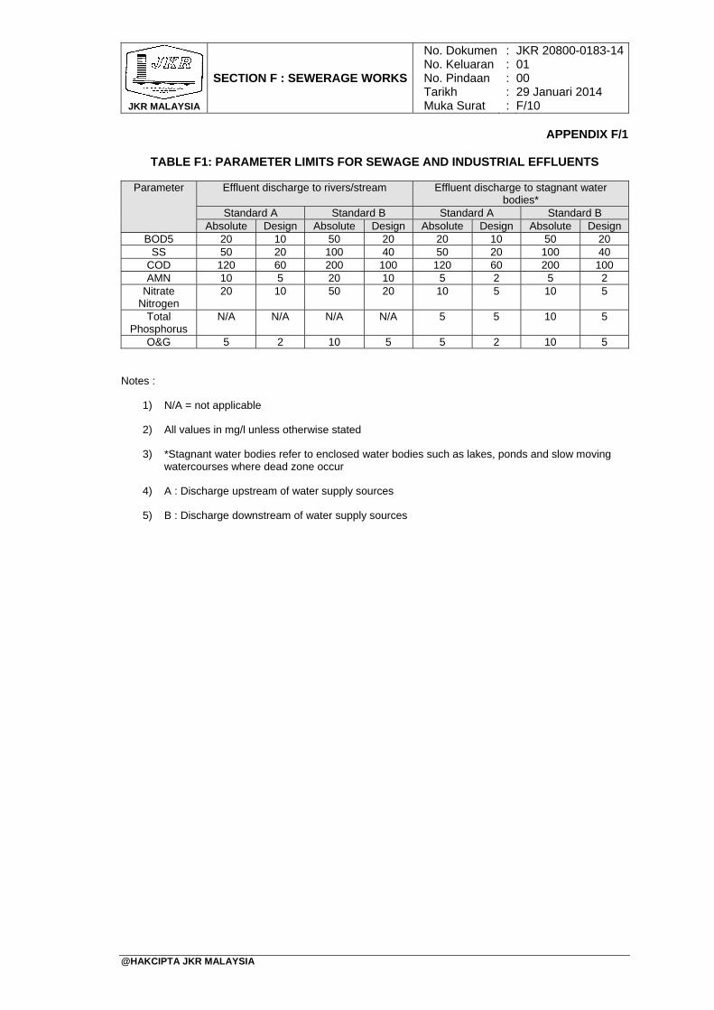
JKR MALAYSIA
SECTION F : SEWERAGE WORKS
No. DokumenNo. KeluaranNo. PindaanTarikhMuka Surat
: : : : :
JKR 20800-0183-1401 00 29 Januari 2014 F/10
@HAKCIPTA JKR MALAYSIA
APPENDIX F/1
TABLE F1: PARAMETER LIMITS FOR SEWAGE AND INDUSTRIAL EFFLUENTS
Parameter Effluent discharge to rivers/stream Effluent discharge to stagnant water bodies*
Standard A Standard B Standard A Standard B Absolute Design Absolute Design Absolute Design Absolute Design
BOD5 20 10 50 20 20 10 50 20 SS 50 20 100 40 50 20 100 40
COD 120 60 200 100 120 60 200 100 AMN 10 5 20 10 5 2 5 2
Nitrate Nitrogen
20 10 50 20 10 5 10 5
Total Phosphorus
N/A N/A N/A N/A 5 5 10 5
O&G 5 2 10 5 5 2 10 5
Notes :
1) N/A = not applicable
2) All values in mg/l unless otherwise stated
3) *Stagnant water bodies refer to enclosed water bodies such as lakes, ponds and slow moving watercourses where dead zone occur
4) A : Discharge upstream of water supply sources
5) B : Discharge downstream of water supply sources
TABLE OF CONTENTS
SECTION G : ROOFING WORKS PAGE
@HAKCIPTA JKR MALAYSIA
1. General 2. Interlocking Concrete Tiles 3. Clay Tiles 4. Pre-painted Aluminium Roofing Sheet 5. Concrete Flat Roofs 6. Pre-painted Steel Roofing Sheet 7. Roofing Sheet For Marine Environment (Coastal Areas) 8. Bituminous Corrugated Roofing Sheets 9. Bituminous Corrugated Roofing Tiles 10. Fibre-cement Corrugated Sheets 11. Heat Insulation
G/1 G/1 G/1 G/1 G/1 G/2 G/4 G/5 G/5 G/5 G/6

@HAKCIPTA JKR MALAYSIA
JKR MALAYSIA
SECTION G : ROOFING WORKS
No. DokumenNo. KeluaranNo. PindaanTarikhMuka Surat
: : : : :
JKR 20800-0183-1401 00 29 Januari 2014 G/1
@HAKCIPTA JKR MALAYSIA
1. General 1.1 Unless otherwise stated, the pitch and laps for each type of roof covering shall be
strictly in accordance with the manufacturer’s recommendation.
1.2 Unless otherwise approved, all roof covering pieces or accessories such as eaves, hips, ridges, valley et cetera, shall be of the same material as the general covering.
2. Interlocking Concrete Tiles 2.1 Interlocking concrete roof tiles shall be laid on timber or steel battens approved for
roofing at spacing and tightly nailed or screwed as recommended by the manufacturer.
2.2 Unless otherwise specified, the concrete roof tiles shall be laid to slope in accordance to the manufacturer’s recommended pitch and to the S.O’s approval. The roof tiles shall conform to MS 797 and unless otherwise specified on the Drawings, it shall be laid on metal trusses system to engineer’s detail and S.O’s approval.
2.3 Tiling fillers consisting of 1:3 cement mortar as specified under SECTION E: NON-STRUCTURAL WALL SYSTEM, shall be provided at the feet of the rafters.
2.4 Verges, ridges, hips, valley tiles and complete with all roofing accessories shall be provided and laid to bond with the general roof tiling works in accordance with the manufacturer’s recommendation.
3. Clay Tiles 3.1 Unless otherwise stated in the Drawings, clay tiles shall be of 470 mm (length) x
284 mm (horizontal width) pattern confirming to BS 402 and shall be free from cracks, chips and warps.
3.2 Clay tiles shall be laid with a minimum head lap of 95mm on timber or steel battens approved for roofing at spacing as recommended by the tile manufacturer. The tiles shall be firmly screwed or nailed at intervals as recommended by the roofing tile manufacturer and as approved by the S.O.
3.3 Ridge capping, hip and valley tiles complete with all roofing accessories shall be provided to match the general tiling works in accordance with the manufacturer’s recommendation. All these shall be bedded in matching 1:3 coloured cement mortar.
4. Pre-painted Aluminium Roofing Sheet Unless otherwise stated, where aluminium roofing sheets are to be used, they shall be of the type, gauge and finish as shown in the Drawings and to be fixed strictly in accordance with the manufacturer’s recommendation.
5. Concrete Flat Roofs
Concrete flat roofs shall be as specified under SECTION D: CONCRETE WORKS.
JKR MALAYSIA
SECTION G : ROOFING WORKS
No. DokumenNo. KeluaranNo. PindaanTarikhMuka Surat
: : : : :
JKR 20800-0183-1401 00 29 Januari 2014 G/2
@HAKCIPTA JKR MALAYSIA
6. Pre-painted Steel Roofing Sheet 6.1 Unless otherwise stated, the metal roof decks shall comply with the following:
6.1.1 Materials
6.1.1.1 The roofing sheets shall be produced from aluminium/zinc alloy
coated steel conforming to MS 1196: “Continous Hot-Dip Aluminium/Zinc Coated Steel Sheet of Commercial, Drawing and Structural Qualities” and AS 1397 “Steel Sheet and Strip-: Hot-Dip Zinc Coated or Aluminium/Zinc Coated”.
6.1.1.2 The pre-painted finish over the aluminium/zinc alloy coated
base steel shall conform to MS 2383: “Prefinished/Pre-painted Sheet Metal Products for Interior/Exterior Building Applications - Performance Requirements” and AS/NZS 2728: “Prefinished/Pre-painted Sheet Metal Products for Interior/Exterior Building Applications - Performance Requirements”.
6.1.1.3 The exterior finish coat shall have a nominal film thickness of 20 µm over 5 µm thick corrosion inhibitive primer on top side or weather side. The backing coat shall be with nominal film thickness of 5 µm over 5 µm corrosion inhibitive primer.
6.1.1.4 Minimum steel yield strength shall be 550 MPa.
6.1.1.5 Minimum aluminium/zinc alloy coating mass shall be 150 g/m² (Coating Class AZ 150) on both surfaces conforming to ISO 9223 Category 3 (C3) environment.
6.1.1.6 The Contractor shall submit material warranty from the manufacturer in accordance with ISO 9223: “Corrosion of Metals and Alloys – Corrosivity of Atmosphere - Classification” of the project site and the format approved by the S.O. Material warranty shall be up to 25 years against perforation by corrosion, 15 years against flake and peel, 10 years against colour fading and 5 years against dirt staining.
6.1.1.7 The Contractor shall submit shop drawings for the S.O’s approval prior to commencement of installation works.
6.1.2 Metal sheet profiles
6.1.2.1 Unless otherwise specified or shown in the Drawings, the metal
sheet profile shall be of a concealed fixing system as approved by the S.O. The roofing sheets shall have the following minimum requirements:
(i) Base Metal Thickness (BMT) = 0.42 mm. (ii) Cover width = 680 mm. (iii) Rib height = 40 mm. (iv) Coating = Pre-painted aluminium and zinc coated
steel with AZ150 (150 g/m²) on both surfaces.
JKR MALAYSIA
SECTION G : ROOFING WORKS
No. DokumenNo. KeluaranNo. PindaanTarikhMuka Surat
: : : : :
JKR 20800-0183-1401 00 29 Januari 2014 G/3
@HAKCIPTA JKR MALAYSIA
6.1.2.2 Where pierced fixing system is specified or shown in the Drawings, the roofing sheet shall have the following minimum requirements:
(i) Base Metal Thickness (BMT) = 0.42 mm. (ii) Cover width = 750 mm (iii) Rib height = 38 mm (iv) Coating = Pre-painted aluminium/zinc coated steel
with AZ150 (150 g/m²) on both surfaces.
6.1.3 Fixing 6.1.3.1 Installation procedures shall conform to the recommendation of
the manufacturer.
6.1.3.2 The roofing sheets shall be installed and fixed according to the following method:
(i) Concealed fixing using approved clips compatible with
the roofing sheet. (ii) Pierced fixing using approved fasteners compatible with
the roofing sheet.
6.1.3.3 The roofing installer shall be registered with CIDB.
6.1.3.4 Metallic swarf and all other debris including nail, screws, mortar, construction materials et cetera shall be swept away from the roof area and gutters regularly, particularly at the end of each day’s work and at completion of the installation works.
6.1.4 Clips and fasteners
6.1.4.1 Fasteners type shall comply with AS 3566 Class 3 and be
certified as such by the supplier of fasteners.
6.1.4.2 The recommended type of fasteners shall conform to the following test:
(i) Salt spray test - 1000 hours (ii) Kesternich test - 15 cycles. (iii) Humidity test - 1000 hours. (iv) UV test - 2000 hours.
6.1.4.3 All fasteners and screws shall be of the self-drilling type either
concealed or screwed fixing, complete with preassembled ethylene propylene diene monomer (EPDM) rubber washers.
6.1.5 Flashing and capping
Approved 0.42 mm BMT ridge capping, flashing, capping and trimming
shall be manufactured to the required shape and sizes. The flashing and capping materials used shall be from the same material as the roofing sheets.
6.1.6 Sealants
Only neutral cure silicone rubber sealant type Dow Corning 780 or equivalent shall be used conforming to AS 3902.
JKR MALAYSIA
SECTION G : ROOFING WORKS
No. DokumenNo. KeluaranNo. PindaanTarikhMuka Surat
: : : : :
JKR 20800-0183-1401 00 29 Januari 2014 G/4
@HAKCIPTA JKR MALAYSIA
6.1.7 Lightning conductors
Aluminium lightning conductor is recommended for use on steel roof system.
6.2 All fixing accessories shall be rust-resistant and of suitable design and construction
as recommended by the manufacturer for the roofing system and as approved by the S.O. All fasteners and screws shall be of the self-drilling type either concealed or screwed fixing, complete with preassembled EPDM rubber washers.
6.3 Identification, storage and packaging of alum/zinc steel roof decking shall be strictly
in accordance with the manufacturer’s recommendation and comply with the S.O.’s requirements.
6.4 All roof decking sheets, capping, flashing et cetera or wall cladding shall be new,
clean, regular, straight and true to shape with sharp defined profiles, free from cracks, chips, bends and defects detrimental to practical use or from other surface imperfections.
6.5 At Site, the sheets shall be lifted from the transport carrier by a crane and properly
stacked clear of the ground, ready to be lifted up to the roof structure for laying. Where sheets are to be manually lifted, care should be taken not drag the sheets to avoid scraping away the surface coating.
6.6 Where storage is necessary, stack heights shall be kept to a minimum and the
sheets shall be stacked in a sloping position. Sheets shall be stacked off a dry firm ground, under cover by tarpaulin or polythene sheets but ventilated and away from building operations. Should the stack sheets become wet, they shall be immediately dried to prevent staining and degradation of the surface coatings.
6.7 The Contractor shall be responsible for the absolute water-tightness of the roof and
must ensure that the method of installation, fixing and fastening decking sheets, caps, flashings et cetera including acoustical, insulation and expansion joints, whenever required shall conform strictly to the manufacturer’s recommendation.
6.8 The completed portions of the roof shall be clear of all metallic particles such as
blind rivet shanks, screws, nuts, nails et cetera and dirty foot prints should be wiped off to avoid early deterioration/corrosion and discolouration. Damages to the coating shall be repaired with touch-up paint as recommended by the manufacturer and approved by the S.O.
7. Roofing Sheet For Marine Environment (Coastal Areas) 7.1 The Contractor shall select the correct type of metal sheet profile to be installed for
coastal areas as recommended by the roof manufacturer and approved by the S.O.
7.2 Unless otherwise specified or shown in the Drawings, the roofing sheet for marine environment shall be metallic coated steel with minimum aluminium/zinc alloy coating mass of 200 g/m² (Coating Class AZ 200) on both surfaces conforming to ISO 9223 Category 4 (C4) and Category 5 (C5) environment.
7.3 Metallic coated steel shall be manufactured and certified by SIRIM according to MS
1196 ‘Continuous Hot-Dip Aluminium/Zinc Coated Steel Sheet of Commercial, Drawing and Structural Qualities’ or AS 1397 ‘Steel Sheet and Strip: Hot-Dip Zinc Coated or Aluminium/Zinc Coated’.
7.4 The pre-painted finish (super polyester paint) type shall be used over the aluminium/zinc alloy coated base steel shall conform to MS 2383: “Prefinished/Pre-
JKR MALAYSIA
SECTION G : ROOFING WORKS
No. DokumenNo. KeluaranNo. PindaanTarikhMuka Surat
: : : : :
JKR 20800-0183-1401 00 29 Januari 2014 G/5
@HAKCIPTA JKR MALAYSIA
painted Sheet Metal Products for Interior/Exterior Building Applications - Performance Requirements” and AS/NZS 2728: “Prefinished/Pre-painted Sheet Metal Products for Interior/Exterior Building Applications - Performance Requirements”
7.5 Fasteners used shall comply with AS 3566 Class 4 and be certified as such by the supplier of fasteners and to the approval of the S.O.
7.6 All fixings and associated components shall be manufactured from compatible
metals and coated conforming to ISO 9223 Category 4 (C4) and Category 5 (C5) environment. Flashings shall be made from the same material as the roofing sheets.
8. Bituminous Corrugated Roofing Sheets
8.1 Unless otherwise shown on the Drawing, the bituminous corrugated roofing sheets
shall have the following minimum requirements: (i) Length = 2000 mm (ii) Width = 950 mm (iii) Cover width = 855 mm (iv) Thickness = 3 mm (v) Weight of material = 3.3 kg/m2 (vi) Thermal resistance R- value = 0.04 mK/W (vii) Thermal conductivity = 0.066 W/mk
8.2 Unless otherwise shown on the Drawings, the Bituminous Corrugated Roofing Sheets shall be laid at a minimum roof pitch of 5° on timber battens at spacing and tightly nailed/screwed as recommended by the manufacturer.
8.3 Ridge capping, nails and screws shall be provided to match the roofing sheets while ridges, verges, eaves, hips, valleys, side-wall and end-wall details shall be fixed strictly in accordance with the manufacturer’s recommendation.
9. Bituminous Corrugated Roofing Tiles 9.1 Unless otherwise shown on the Drawing, the bituminous corrugated roofing tiles
shall have the following minimum requirements: (i) Length = 1060 mm (ii) Width = 400 mm (iii) Wave height = 40 mm (iv) Thickness = 3 mm
9.2 Bituminous roofing tiles shall be laid at a minimum roof pitch of 9° and on timber or steel battens approved for roofing at spacing and tightly nailed/screwed as recommended by the manufacturer.
9.3 Ridge capping, nails and screws shall be provided to match the roofing tiles while ridges, verges, eaves, hips, valleys, side-wall and end-wall details shall be fixed strictly in accordance with the manufacturer’s recommendations.
10. Fibre-cement Corrugated Sheets 10.1 Fibre-cement corrugated sheets shall comply with MS 1224. The thickness of the
sheets shall be 3 mm thick for shallow corrugation and 4 mm thick for medium
JKR MALAYSIA
SECTION G : ROOFING WORKS
No. DokumenNo. KeluaranNo. PindaanTarikhMuka Surat
: : : : :
JKR 20800-0183-1401 00 29 Januari 2014 G/6
@HAKCIPTA JKR MALAYSIA
corrugation. The cement shall comply with MS 522: Part 1. Asbestos processed or unprocessed shall not be added to fibre-cement sheets.
10.2 The surface intended to be exposed to the weather shall have a generally smooth finish. Variations of the surface appearance which do not impair the characteristics of the sheets as defined in MS 1224 are permitted.
11. Heat Insulation 11.1 General
Heat insulation system shall comply with MS 1020. Samples of the insulation material shall be submitted to the S.O for approval before they are used and subsequent delivery shall be up to the standard of samples approved.
11.2 Reflective Foil
11.2.1 Reflective foil shall be fire retardant double sided aluminium reflective foil bonded to reinforced high density polyethylene woven fabric.
11.2.2 The reflective foil materials used shall conform to fire safety requirements and BS 476: Fire Test on Building Materials and Structures on the following test: (i) Non-combustibility test for materials. (ii) Method of test for fire propagation for products. (iii) Method of test to determine the classification of the surface spread of
flame.
11.2.3 Reflective foil properties shall conform to the following: (i) Thickness : 137 ± 20 micron thick. (ii) Grammage : 163 ± 10g / m2. (iii) Tensile strength : 500 N / 50 mm (MD), 500 N / 50 mm (Cross
Direction). (iv) Emissivity ASTM E408 ≤ 0.05(97±2%) / Reflectivity = 95% (v) Initial Tear resistance: ASTM D1004 >30N (vi) Tear Propagation: DIN53363 > 600 N/mm (CD) / 800 N/mm (MD)
11.2.4 Reflective foil material may be used on its own with all types of roofs except
with metal decking roof. Where roof is of metal decking, the reflective insulation material shall be laid below stone wool or glass wool for effective thermal and acoustic performance.
11.2.5 The reflective foil material shall be installed strictly in accordance with the manufacturer’s recommendation. A uniform air space of 20 mm between the tile roof covering and the insulation material shall be provided to ensure the effectiveness of the reflective surface. All punctures shall be effectively sealed with similar reflective material to prevent air leakage and moisture transfer.
11.2.6 The reflective foil surface shall be free from any thin film of oil, plastic or lacquer coatings. All dust and/or moisture, if any, shall be thoroughly cleaned prior to installation. All dust and/or trademarks shall be limited to a maximum of 5% of the total reflective area. The insulation material shall be fitted closely around electrical outlet boxes, plumbing and et cetera, and taped securely to eliminate gaps or voids through which air or water vapour might pass into the cooler space.
JKR MALAYSIA
SECTION G : ROOFING WORKS
No. DokumenNo. KeluaranNo. PindaanTarikhMuka Surat
: : : : :
JKR 20800-0183-1401 00 29 Januari 2014 G/7
@HAKCIPTA JKR MALAYSIA
11.3 Glass Wool Insulation 11.3.1 Unless otherwise shown in the Drawings, glass wool insulation shall be 75
mm thick. It shall have R-Value @ R2.0 m²KW (tested at a mean temperature of 20°C based MS1020 tested according to ASTM C177/C518). The glass wool insulation material used shall conform to BS 476 for Fire tests on building materials and structures on the following: (i) Non-combustibility test for materials. (ii) Method of test for fire propagation for products. (iii) Method of test to determine the classification of the surface spread of
flame.
11.3.2 The glass wool insulation material used shall be of no added urea formaldehyde and as approved by the S.O. Glass wool insulation shall be fixed in accordance with the manufacturer’s recommendations and to the approval of the S.O.
11.3.3 Where single skin metal roof is applied, galvanized wire mesh BRC 3316 or equivalent shall be used to support the reflective foil and the glass wool insulation.
11.4 Stone Wool Insulation
11.4.1 Unless otherwise shown in the Drawings, stone wool insulation shall be 50
mm thick minimum. It shall have R-Value @ R2.0 m²KW (tested at a mean temperature of 20°C based MS1020 tested according to ASTM C177/C518). The stone wool insulation material used shall conform to BS 476 for Fire tests on building materials and structures on the following: (i) Non-combustibility test for materials. (ii) Method of test for fire propagation for products. (iii) Method of test to determine the classification of the surface spread of
flame.
11.4.4 The stone wool insulation shall conform to the following: (i) Thermal conductivity 0.034 - 0.036 W/mK at 20°C mean temperature
tested in accordance to ASTM C518. (ii) Noise reduction coefficients (NRC) of up to 1.0 tested to BS EN ISO
354 at 50 mm thickness. (iii) Non-combustible according to BS 476 Part 4 or EN 13501-1 and
melting point of at least 1000°C in accordance to ASTM E794. (iv) No CFCs, HFCs, HCFCs or asbestos shall be used in the manufacture
of the product. (v) No perceptible odor shall be present when tested in accordance to
ASTM C665. (vi) Not sustaining fungus growth under normal conditions according to
ASTM C1338. (vii) The metal plates (steel and aluminium) in contact with the insulation
shall show no corrosion greater than that observed on the comparative plates in contact with sterile cotton according to ASTM C665.
(viii) Flame spread index less than zero (0) and smoke developed index less than five (5) according to ASTM E84.
(ix) Total volatile organic compound (VOC) emission shall be less than 0.25 mg/m3 and particles emission shall be less than 0.02 mg/m3 tested according to ASTM D5116.
(x) Moisture absorption shall be less than or equal to 0.04 % volume according to ASTM C1104/C1104M and water absorption shall be less
JKR MALAYSIA
SECTION G : ROOFING WORKS
No. DokumenNo. KeluaranNo. PindaanTarikhMuka Surat
: : : : :
JKR 20800-0183-1401 00 29 Januari 2014 G/8
@HAKCIPTA JKR MALAYSIA
than or equal to 0.5 kg/m² (short-term immersion) according to EN 1609.
11.4.3 The stone wool insulation material used shall be of no added urea
formaldehyde and as approved by the S.O. Stone wool insulation shall be fixed in accordance with the manufacturer’s recommendation and to the approval of the S.O.
11.4.4 The insulation material must be protected from the exposure of rain, water immersion and chemical contamination during the storage and installation. If the insulation are in contact with water, adequate drying time must be allowed to ensure that the insulation are completely dried prior to covering of the roof covers.
11.4.5 The stone wool insulation shall be installed to the thickness specified and place butt jointed. Wherever possible the Contractor shall avoid the compression of the insulation material.
11.4.6 Where single skin metal roof is applied, galvanized wire mesh BRC 3316 or equivalent shall be used to support the reflective foil and the stone wool insulation.
TABLE OF CONTENTS
SECTION H: TIMBER, JOINERY AND IRONMONGERY WORKS
PAGE
@HAKCIPTA JKR MALAYSIA
1. General 2. Timber Grades And Size Tolerances 3. Treatment Of Timber 4. Moisture Content And Storage 5. Structural Assemblies Of Timber 6. Timber Joints 7. Prefabricated Timber Roof Truss System 8. Glued Laminated Timber For Structures 9. Carpentry Works 10. Joinery Works 11. Timber Floor Finish 12. Ceiling Timber Battens 13. Timber Partitions 14. Fascia And Barge Boards 15. External Boarding 16. Staircase And Balustrades 17. Timber Solid Panel Doors 18. PVC Doors 19. Products And Materials 20. Ironmongery 21. Built-in Furniture
TABLE H1 : Schedule Of Timber Grouping And Usage TABLE H2 : Schedule Of Timber Species In Accordance
With Strength Grouping (S.G) TABLE H3 : Schedule Of Moisture Contents (M.C) Of
Timber For Various Positions In Building TABLE H4 : Natural Durability Classification Of Peninsular
Malaysia Timbers For Ground Contact TABLE H5 : Natural Durability Classification Of Sarawak
Timbers For Ground Contact TABLE H6 : Properties Of Malaysian Timber TABLE H7 : Schedule Of Ironmongery TABLE H8 : Timber Species For The Manufacturing Of
Glued Laminated Timber Components APPENDIX H/1 : Glued Laminated Timber Performance
Warranty (Specimen)
H/1 H/1 H/1 H/3 H/3 H/4 H/5 H/7 H/12 H/13 H/13 H/13 H/14 H/14 H/14 H/14 H/15 H/15 H/15 H/17 H/17 H/20 H/21 H/22 H/23 H/24 H/25 H/26 H/28 H/29

JKR MALAYSIA
SECTION H : TIMBER, JOINERY AND IRONMONGERY WORKS
No. DokumenNo. KeluaranNo. PindaanTarikhMuka Surat
: : : : :
JKR 20800-0183-1401 00 29 Januari 2014 H/1
@HAKCIPTA JKR MALAYSIA
1. General 1.1 Unless otherwise specified or shown in the Drawings, the timber species used for
the Works shall be as stated hereinafter in the TABLE H1. The strength grouping for timber shall be in accordance with MS 544 as shown hereinafter in the TABLE H2.
1.2 All carpentry and joinery work shall include all necessary notching, halving,
morticing and tenoning, wedging, scarfing, dovetailing, sinking for heads of bolts and nuts and trimming for opening.
1.3 All carpentry work shall be left with a sawn surface except where particularly described to be wrot. All joinery shall be wrot and finished with sand paper as required and all sizes stated are the finished sizes. Sizes for carpentry shall be within the tolerances stated in sub-section 2.1 and sizes for joinery shall be within the tolerances stated in sub-section 2.2.
1.4 Unless otherwise indicated in the Drawings, all fire protection materials and systems must show evidence that they have been subjected to the fire resistance test in accordance with BS 476 or other approved equivalent standards.
2. Timber Grades And Size Tolerances 2.1 Unless otherwise specified, sawn timber for carpentry work shall be as stated
hereunder:
(i) Select Grade - for roof truss (ii) Standard Structural Grade - for structural work (iii) Sound Grade - for General Market Specification (GMS) and strips (iv) Serviceable Grade - for scantling
2.2 Grading shall be carried in accordance with the Malaysian Grading Rules (MGR) by
timber graders registered with the MTIB. Every timber consignment shall be accompanied by the Grading Summary certified by the registered timber grader. The sizes of sawn timber, except where otherwise specified, shall be within the margin of permissible variations stated hereunder:
(i) For widths, depths or thicknesses not exceeding 75 mm - within 3 mm of the
specified size (ii) For widths, depths or thicknesses exceeding 75 mm - within 5 mm of the
specified size.
2.3 The Contractor shall provide any necessary blocks, wedges or battens to compensate for irregular surfaces caused by any variations in size of timbers hereby permitted.
2.4 Unless otherwise specified, sawn timber for joinery work shall be of Sound Grade
(General Market Specification (GMS) and Strips) and Serviceable Grade (Scantlings). The finished size for joinery, unless otherwise specified, shall be within the margin of permissible variation stated hereunder:
(i) For widths, within 3 mm of the specified finished size. (ii) For thicknesses, within 2 mm of the specified finished size.
3. Treatment Of Timber
3.1 All timber except the heartwood of the naturally durable timbers as scheduled in
TABLE H2 hereinafter and timber for formwork, scaffolding, and other temporary
JKR MALAYSIA
SECTION H : TIMBER, JOINERY AND IRONMONGERY WORKS
No. DokumenNo. KeluaranNo. PindaanTarikhMuka Surat
: : : : :
JKR 20800-0183-1401 00 29 Januari 2014 H/2
@HAKCIPTA JKR MALAYSIA
works shall be impregnated by means of vacuum pressure processes in accordance with MS 360 using copper/chrome/arsenic (CCA) wood preservatives conforming to MS 733 in the treatment plant registered with the MTIB.
3.2 If a timber component has sufficient natural resistance to decay and insect
attack by virtue of the natural durability of its heartwood, it may be used without treatment even where the hazard exists. The natural durability classification of Peninsular Malaysia and Sabah and Sarawak timbers for ground contacts can be found in MS 360 and as shown in TABLE H4 and TABLE H5. Sapwood should not be used without preservative treatment
3.3 Unless otherwise specified, the average moisture content for all timber shall not exceed 25% in accordance with MS 360. The moisture content shall be determined in accordance with one of the methods given in MS 837.
3.4 All timber shall be sawn or planed before treatment to achieve the finished cross-section required. As far as possible, all cross-cutting, boring, drilling or other processing should be carried out before treatment.
3.5 The pH value of the treating solution shall not be higher than 3.0 when determined by a glass electrode or pH paper at ambient temperature in accordance with MS 360.
3.6 The net dry salt retention shall be determined in accordance with one of the methods given in MS 360 and MS 821. The minimum salt penetration shall be determined by one the test methods given in MS 833.
3.7 The material shall be collected by drilling to the required depth as recommended and shown in MS 360 -TABLE 4. It can also be collected by sawing to the required depths, and then chipped to the small size. Either sawdust or chipped materials shall be ground to fine powder.
3.7.1 The minimum nett dry salt retention for CCA shall be as shown in the table
below:
No Use Minimum Net Dry Salt Retention For CCA
i) Interior and above the ground 5.6 kg/m³
ii) Exterior and above the ground 8.0 kg/m³
iii) Exterior and in contact with the ground (other than foundation piles)
12.0 kg/m³
3.7.2 All sapwood shall be fully penetrated by the preservative and for
heartwood, the depth of penetration shall be 12 mm.
3.8 The Contractor, when required by the S.O. shall produce a certificate from a preservative treatment plant which certifies that timber required to be impregnated by means of vacuum pressure processes has been impregnated and has achieved the necessary nett dry salt retention. Notwithstanding the certificate, the S.O. reserves the right to carry out independent tests to determine the nett dry salt retention and the result so obtained shall be conclusive.
JKR MALAYSIA
SECTION H : TIMBER, JOINERY AND IRONMONGERY WORKS
No. DokumenNo. KeluaranNo. PindaanTarikhMuka Surat
: : : : :
JKR 20800-0183-1401 00 29 Januari 2014 H/3
@HAKCIPTA JKR MALAYSIA
3.8.1 Treatment certificate
3.8.1.1 A treatment certificate shall be produced for each batch of timber delivered from the treatment plant. The relevant charge sheets shall be attached with each treatment certificate. The following information shall appear on the certificate:
(i) name and address of buyer; (ii) project title/reference; (iii) name of treating company; (iv) name of preservative(s) used; (v) average retention of preservative obtained; (vi) charge sheet number and date of treatment; (vii) species of timber treated together with sizes and volume; (viii) commodity and hazard class; and (ix) other registration number (where applicable)
3.8.1.2 The certificate shall be signed by authorized personnel of the treating company, certifying that the timber has been treated in accordance with MS 360.
4. Moisture Content And Storage 4.1 At the time of installation, the moisture content of the timber for the various
applications shall not exceed that as specified in TABLE H3.
4.2 Moisture content for foundation piles, formworks and temporary works is not critical for these applications and therefore is not specified.
4.3 Moisture content of timber shall be determined in accordance with MS 837.
4.4 On delivery to the site, all timber other than timber for foundation piles, formworks and temporary works shall be properly open-stacked, under cover. Kiln dried timber shall be properly wrapped and stored under cover if it is not used immediately.
5. Structural Assemblies Of Timber
5.1 The workmanship and method of assembly of structural timber shall generally be in accordance with MS 544 and in particular, the following requirements:
(i) The quality of the surface, as finished, shall be appropriate to the position and
use of the timber. (ii) When grade or other necessary marks are removed, provisions shall be made
for remarking in accordance with Malaysian Grading Rules. Surfaces at any joint in an assembly shall be such that the parts may be brought into contact over the whole area of the joint before connectors are inserted or any pressure or restraint from the fastening is applied. These surfaces shall have a good sawn or planed finish.
(iii) Bearing surfaces of notches and other cuttings shall be true and smooth and in
appropriate relation to the other surfaces of the piece.
5.2 Notches other than at the ends of beams shall be U-shaped formed by parallel cuts to previously drilled holes. The diameter of the hole shall be equal to the width of the required notch.
JKR MALAYSIA
SECTION H : TIMBER, JOINERY AND IRONMONGERY WORKS
No. DokumenNo. KeluaranNo. PindaanTarikhMuka Surat
: : : : :
JKR 20800-0183-1401 00 29 Januari 2014 H/4
@HAKCIPTA JKR MALAYSIA
5.3 Where splitting is likely to have a deleterious effect, end sealing is recommended. For timbers known to split and check especially after installation, the ends of the boards and scantlings shall be protected with a coating designed to minimise end checking and checking and splitting. In severe cases where the ends and sides of heavy joists of timbers are liable to excessive split and check due to exposure to windward slanting sunlight, appropriate skirting or cover with a thin timber board shall be necessary.
6. Timber Joints
6.1 When solid timber members are to be jointed together using mechanical fasteners, the workmanship and method of assembly shall be in accordance with MS 544 Part 5. The mechanical fasteners are as listed below:
6.1.1 Nailed joint
Where necessary to avoid splitting, nails shall be driven into pre-drilled
holes or diameter not greater than four-fifths of the diameter of the nails. Care shall be taken to avoid placing nails in any end split.
6.1.2 Screwed joint
Lead holes shall be used to ensure good workmanship in making screwed joints. The diameter of the hole for the shank shall be equal to the diameter of the shank, and for the threaded portion, the diameter of the hole shall not be greater than seven-eighth of the diameter of the root diameter of the screw thread adjacent to the shank. Care shall be taken to avoid placing screws in any end split.
6.1.3 Bolted joint
6.1.3.1 Bolt holes shall be drilled to diameters as close as possible to
the nominal diameter of the bolt and in no case more than 2 mm larger than the bolt diameter. Care shall be taken to avoid placing a bolt in any end split. A minimum of one complete thread shall protrude from the nut.
6.1.3.2 A washer shall be fitted under the head of each bolt and under each nut. The minimum sizes of washers are as given in Part 6 of MS 544. Where joints using split-rings are to be used, as shown in the Drawings, the members of the joints shall be fitted together in their appropriate positions and clamped or spiked together before drilling. Alternatively, drilling jigs or multiple head boring machines may be used, or individual members may be marked out from the setting-out or by use of prepared templates.
6.1.3.3 If either of the latter methods is employed, sample members
(usually the first ones produced) shall be carefully checked against the setting-out.
6.1.3.4 In all instances holes for bolt positions shall be accurately
determined by reference to the point intersection of the centre lines of the member. Great care is necessary if the first set members marked out is to be used subsequently as drilling templates. Greater accuracy can usually be obtained by the use of special marking or drilling templates located by a pin at the intersection of the center lines.
JKR MALAYSIA
SECTION H : TIMBER, JOINERY AND IRONMONGERY WORKS
No. DokumenNo. KeluaranNo. PindaanTarikhMuka Surat
: : : : :
JKR 20800-0183-1401 00 29 Januari 2014 H/5
@HAKCIPTA JKR MALAYSIA
6.1.3.5 Bolts holes shall be drilled at right angles to the surface of the joint. The contact surfaces of the members should be grooved to the appropriate dimensions as given in Part 6 of MS 544.
6.1.3.6 Drilling and grooving may be done in a single operation; alternatively, if the hole is predrilled the pilot of the grooving tool shall fit in the bolt hole, thus centering the groove about the hole.
6.1.3.7 Care shall be taken to ensure that all chips and shavings are
removed, and rings shall be expanded before being placed in the grooves.
6.1.3.8 The joint shall be finally assembled and bolts inserted. Washers
of the correct dimension shall be placed under the head of the bolt and the nut, and the nut tightened to hold the members together.
6.1.3.9 Recess for shear-plate connectors shall be accurately cut by
means of a suitable tool to be appropriate dimensions as given in MS 544 - Part 6.
6.1.3.10 Assembly of units shall be done on a level bed and in such a
way as to avoid damage to any of the members and so that the finished structural units conform to detailed Drawings and specification supplied.
6.1.3.11 When assembly is to be performed on the site, one set of
component parts shall be fitted together and dismantled prior to dispatch to the site, in order to ensure that the assembled structural units conform to the detailed Drawings and Specifications. Twisted or damaged members shall be replaced before erection on the site.
6.1.3.12 Before proceeding with bulk production, a complete assembly
of one of each framed truss or other structural unit shall be checked to prove the accuracy of the templates, et cetera A similar check shall be carried out from time to time to control the wear and tear on templates and gauges.
6.1.3.13 Timber members and built-up units shall be marked in
accordance with a marking diagram.
7. Prefabricated Timber Roof Truss System
7.1 All prefabricated components shall be manufactured only by reputable licensed truss suppliers and approved by the S.O. This supplier duly termed as ‘System Provider’ is responsible for the analysis, design, detailing, drawing, manufacture, material, handling and erection of the roof members, and their ancillary fixing components. The full requirement is outlined in the Specification for Prefabricated Timber Roof Trusses (JKR 20601-0190-12) or the latest edition published by JKR.
7.2 System Provider
7.2.1 The System Provider (S.P.) is a supplier of a proprietary roof truss system appointed by the Contractor and approved by the S.O., which employs Quality Assurance procedures in the design, detailing, connection, bracing,
JKR MALAYSIA
SECTION H : TIMBER, JOINERY AND IRONMONGERY WORKS
No. DokumenNo. KeluaranNo. PindaanTarikhMuka Surat
: : : : :
JKR 20800-0183-1401 00 29 Januari 2014 H/6
@HAKCIPTA JKR MALAYSIA
erection criteria and manufacture of truss components for the structural roof truss system.
7.3 Duties Of Professional Engineer
7.3.1 The S.P. shall appoint a Professional Engineer (P.E.) whose duties shall
include the following:
(i) Preparation of roof truss analysis and design; (ii) Preparation of drawings; (iii) Design changes in every stage of work; (iv) Certification for completion of roof truss installation; (v) Final certification for roof truss installation prior to issuance of
Certificate of Practical Completion for the whole Works to the Contractor.
7.4 Fabricator
All trusses shall only be assembled by licensed fabricators approved by the S.P.
and registered with CIDB. A copy of the CIDB registration certificate shall be submitted to the S.O. for verification.
7.5 Installer
All installation works shall be executed and supervised by qualified personnel with
valid certificates issued by CIDB. The S.O. shall verify the identification and qualification of the installer prior to the installation.
7.6 General Truss Limitation
7.6.1 Prior to any pre fabricated timber roof trusses works, the following general
limitation shall be applied:
(i) Maximum unsupported truss span 12 m with permitted deviation of ±0.05 m.
(ii) Maximum truss spacing of 1.2 m with permitted deviation of ±0.025 m.
(iii) The minimum basic wind speed shall be 35 m/s. However, the minimum basic wind speed shall be increased to 41 m/s for lightweight roof covering.
(iv) Maximum roof pitch shall be of 45˚.
7.7 Analysis, Design Report And Drawings Submission
7.7.1 The S.P. through the Contractor shall propose to the S.O. or his approval a roof truss system which is safe, functional and conforming to design standard. Submission of proposal shall include truss analysis, design report, and construction drawings. The truss analysis shall indicate all loads, load combinations, connections criteria, bracings and tie-down of the truss. Design output of the truss members, battens, connections, tie-down and wall plates, anchors, bracings, truss accessories, splicing and stiffeners where related to the analysis shall be included in the design report. (Refer to Appendix 3 of JKR 20601-0190-12)
7.7.2 All details in the construction drawings shall be sufficient to enable checking against the analysis and design report, by specifying and providing not limited to: the truss layout and configuration, timber grades, section properties of members, length of members in each truss configuration, properties of truss accessories, specification of fastener and
JKR MALAYSIA
SECTION H : TIMBER, JOINERY AND IRONMONGERY WORKS
No. DokumenNo. KeluaranNo. PindaanTarikhMuka Surat
: : : : :
JKR 20800-0183-1401 00 29 Januari 2014 H/7
@HAKCIPTA JKR MALAYSIA
anchor, tie-down and anchoring details and all types of connection details including the connection of all attachments to the trusses.
7.7.3 Technical specifications for fastener and anchor of which the design refers
to shall also be submitted. Verification test certificate from an approved accredited laboratory on the technical parameter specified in the technical specifications shall be submitted upon request by the S.O.
7.8 Warranty
7.8.1 When a prefabricated timber roof truss system is used, the Contractor shall
submit to the S.O. a warranty from the S.P. with the following provisions: (i) The products used are genuine and free from manufacturing defects; (ii) The prefabricated timber roof truss system is installed in accordance
with the S.P.’s instructions, guidance and specifications that will deliver the specified level of performance;
(iii) The warranty certificate shall cover a period of ten (10) years from the date of Certificate of Practical Completion against any defect or failure due to the installation and workmanship by the S.P.’s registered panel installer.
8. Glued Laminated Timber For Structures
8.1 General
8.1.1 This sub-section shall apply to the construction of all structures or parts of structures to be composed of glued laminated timber manufactured by gluing together individual pieces of dimensioned timber with or without steel joints and connectors. The work shall be carried out all in accordance with this specification and the lines, levels, grades, dimensions and cross-sections shown in the Drawings and as required by the S.O.
8.1.2 All glued laminated timber building components shall be manufactured and assembled by licensed glued laminated timber manufacturers approved by the S.O. The Contractor shall provide the necessary documents relating to the proposed manufacturer such as valid licenses or other certificates to the S.O. for approval prior to the commencement of any manufacturing work.
8.1.3 All glued laminated timber members shall be manufactured in a factory
which has quality control and quality assurance procedures in place as approved by the S.O. The S.O. reserves the right to visit the factory before giving any approval.
8.1.4 Prior to fabrication, the Contractor shall notify the S.O. on the dates of tests
that shall be carried out. The S.O. may appoint a representative in the event the S.O cannot be present during the tests. The Contractor shall forward a copy of the test results jointly certified by the manufacturer for the S.O.’s acceptance and approval.
8.2 Material
8.2.1 Timber
8.2.1.1 Unless specified otherwise, the timber species used for the
manufacturing of glued laminated timber components shall be selected from Malaysian tropical hardwoods that satisfy the
JKR MALAYSIA
SECTION H : TIMBER, JOINERY AND IRONMONGERY WORKS
No. DokumenNo. KeluaranNo. PindaanTarikhMuka Surat
: : : : :
JKR 20800-0183-1401 00 29 Januari 2014 H/8
@HAKCIPTA JKR MALAYSIA
requirements for strength classes D40 to D70 when graded to Hardwood Structural Grade (HSG) in accordance with BS 5756. A list of timber species that satisfies the requirements is shown in TABLE H8 of this specification.
8.2.1.2 The timber species should attain sufficient natural durability and resistance to decay and insect attack as stipulated in MS 544: Part 10.
8.2.1.3 Timber of single species or a mixture of species can be used in
a glued laminated timber structural frame, provided that it is proven to be suitable for the manufacturing of glued laminated timber by the qualification test given in MS 758. Lamination of a glued laminated timber member shall not be of a mixture of different timber species.
8.2.1.4 The visual strength grading for all timber used for structural
works should be visually graded based on the grading requirements of MS 1714: Specification for Visual Strength Grading of Tropical Hardwood Timber. The visual grading shall be carried out by timber graders registered with MTIB.
8.2.1.5 The Contractor is to supply all timber used in the manufacturing
of glued laminated timber component to be of Hardwood Structural Grade as defined under MS 1714.
8.2.2 Moisture content for non treated timber
8.2.2.1 At assembly, the moisture content in every lamination shall be
in the range of 8% to 15%. The range of moisture content of the laminations in a glued laminated timber member shall be not greater than 4%.
8.2.2.2 Method for the determination of the moisture content of timber is as stipulated in MS 837.
8.2.3 Moisture content for treated timber
8.2.3.1 At assembly, the moisture content in every lamination shall be
in the range of 11% to 18%. The range of moisture content of the laminations in a glued laminated timber member shall be not greater than 4%.
8.2.3.2 Method for the determination of the moisture content of timber is as stipulated in MS 837.
8.2.4 Adhesive
8.2.4.1 The adhesive shall be capable of producing strong and durable
joints, ensuring that the integrity of the bond is maintained throughout the intended lifetime of the structure. The adhesive shall meet the requirement for adhesive Type I and minimum Service Class 2 as stipulated in MS 758.
8.3 Laminations And Bonding
8.3.1 The individual laminations shall be end jointed to the final length before
planing.
JKR MALAYSIA
SECTION H : TIMBER, JOINERY AND IRONMONGERY WORKS
No. DokumenNo. KeluaranNo. PindaanTarikhMuka Surat
: : : : :
JKR 20800-0183-1401 00 29 Januari 2014 H/9
@HAKCIPTA JKR MALAYSIA
8.3.2 Grooving of laminations to reduce the effect of cupping is permitted. In each lamination one groove is permitted in the middle part of the cross section, with a maximum width of 4 mm and a maximum depth of one third of the lamination thickness. Grooves in adjacent laminations shall be staggered by at least the thickness of the laminations.
8.3.3 When laminations are jointed by finger joints these shall be produced in
conformity with BS EN 385 or equivalent Malaysian standard.
8.3.4 Where a lamination for horizontal glued laminated timber consists of two boards side by side and the edges are not bonded, the edge-joints in adjacent laminations shall be staggered laterally by at least the lamination thickness. For members used in Service Class 2 the outer lamination on each face shall be edge-bonded. For members used in Service class 3 the outer four laminations on each face shall be edge-bonded.
8.3.5 Laminations in vertical glued laminated timber to be used in Service Class
2 are not required to be edge-bonded, but the edge joints in adjacent laminations shall be staggered by at least one third of the board width. In members to be used in Service Class 3 the outer laminations shall be edge-bonded.
8.3.6 The laminations shall be planed or similarly finished before bonding. The
planing shall be carried out no more than twenty four (24) hours before bonding, unless the species and the storage environment are such that unacceptable surface changes will not take place. With species that are difficult to bond, e.g. have high resin content or where the laminations have been treated with preservative, planing shall be carried out within 6 hours of bonding. It is the responsibility of the glued laminated timber manufacturer to qualify any procedures used and to determine the permissible delay between machining and gluing.
8.3.7 The maximum permitted deviation from the average thickness within a
lamination length of 1 m is 0.2 mm. Where non-gap-filling adhesives are used the limit deviation shall no exceed 0.1 mm. The difference in thickness over the cross-sectional width of the lamination shall be less than 0.15% of the width and in no case exceed 0.3 mm.
8.3.8 At the time of bonding the surfaces of laminations shall be clean. The
adhesive spread shall be uniform and in sufficient quantity in accordance with the recommendations of the adhesive manufacturer.
8.4 Cramping
8.4.1 The cramping arrangement shall ensure a uniform pressure over the glue
line. The pressure shall be that specified in the adhesive manufacturer’s instructions for the adhesive used but in no case shall it be less than 0.7 N/mm2. The application of pressure at a suitable temperature shall be completed within the closed assembly time, when a continuous ‘squeeze out’ or ‘bead’ along the edge of each glue line shall be produced.
8.4.2 For curved members higher cramping pressures shall be applied and in such a way that the laminations can slide over each other in the lengthwise direction to avoid open glue lines. Sufficient pressure shall be maintained during cramping. Tightening up shall be carried out as necessary, and in all cases immediately after initial cramping.
JKR MALAYSIA
SECTION H : TIMBER, JOINERY AND IRONMONGERY WORKS
No. DokumenNo. KeluaranNo. PindaanTarikhMuka Surat
: : : : :
JKR 20800-0183-1401 00 29 Januari 2014 H/10
@HAKCIPTA JKR MALAYSIA
8.5 Preservative Treatment 8.5.1 Where the timber used is not naturally durable (as specified in TABLE H2),
it shall be preservative treated. The treatment of timbers shall be as specified in sub-section 3: Treatment of Timber of this specification.
8.5.2 If any other preservative chemical is used, contractor shall provide necessary documents as may be required by the S.O to prove the efficiency of the chemical treatment.
8.6 Coating Specification
8.6.1 All glued laminated timber members shall be coated with a minimum of two
coats of clear construction sealer. The sealer shall be applied in accordance with the manufacturer’s specification and to the S.O.’s approval. The Contractor shall rectify any damage to the coating after the erection has been carried out. The Contractor shall also provide details of the sealer used to the S.O. for record.
8.6.2 All glued laminated timber shall receive an additional coat of protective sealer before shipping/transport and shall be properly wrapped for protection during shipping/transport and erection. The wrapping should be left in place as long as possible until permanent protection from the weather is in place.
8.7 Submission Of Documentation
8.7.1 Prior to the manufacture and fabrication of the glued laminated timber, the
Contractor shall provide two (2) copies of the following documents for the S.O.’s approval: (i) Particulars of the manufacturer (ii) Quality assurance programme of the manufacturing process (iii) Method statement for assembly, installation, handling and
transportation (iv) Manufacturer’s fabrication drawings (v) Manufacturer’s assembly drawings (vi) Grading summary of timber to be used in the manufacturing of glued
laminated timber, issued by timber grader certified by MTIB (vii) Results of qualification tests
8.8 Production Quality Control
8.8.1 The Contractor shall establish and maintain documented factory production
control to ensure that the produced glued laminated timber members conform to the design requirement as demonstrated in the qualification tests.
8.8.2 From each work shift and each production line, a representative sample of end joint shall be drawn and tested in flatwise bending as described in BS EN 385. For each production line and shift the bending strength is acceptable is if one of the condition stated in sub-section 7.1.2 of MS 758:2001 is met.
8.8.3 Also, from each shift which gluing is carried out, one full cross-sectional
specimen shall be taken for every press load or every 10 m3 of production. The specimen shall be cut from a cured glued laminated timber member produced during each work shift. If all tests for a three-month period satisfy
JKR MALAYSIA
SECTION H : TIMBER, JOINERY AND IRONMONGERY WORKS
No. DokumenNo. KeluaranNo. PindaanTarikhMuka Surat
: : : : :
JKR 20800-0183-1401 00 29 Januari 2014 H/11
@HAKCIPTA JKR MALAYSIA
the requirements the number of samples may be reduced to not less than half the number prescribed above.
8.8.4 The Contractor shall provide information on the glue line integrity, results of
delamination tests and results of glue line shear test which shall not be less than as stipulated in MS 758.
8.8.5 The values for manufactured glued laminated timber shall not be less than
the value for designed glued laminated timber. The values of the manufactured glued laminated timber properties shall be determined in accordance with MS 544: Part 2 or AS/NZS 4063.
8.9 Initial Qualification Tests
8.9.1 The Contractor shall be fully responsible to carry out qualification tests
which shall be witnessed by the S.O. The Contractor shall carry out a qualification test whenever a new process or process change involving new adhesive, species combination, finger joint profile and lamination thickness.
8.9.2 Qualification tests
8.9.2.1 Unless otherwise stated and approved by the S.O. in writing, qualification tests shall be carried out on completed samples of glued laminated timber members before any actual manufacturing is allowed.
8.9.2.2 The tests shall cover the determination of characteristic strength of glued laminated timber member in bending, compression, tension and shear and characteristic modulus of elasticity in bending, and shall be determined by undertaking tests on completed 300 mm deep glued laminated timber members in accordance with AS/NZS 4063 and MS 758:2001.
8.9.2.3 The characteristic bending strength shall be obtained from
flatwise bending test of the joint in the lamination.
8.9.3 The Contractor shall declare the manufactured glued laminated timber properties are as required by the designer and as shown in the drawings. The required properties to be declared are characteristic values for bending strength, modulus of elasticity, compression strength, shear strength and tension strength.
8.10 Handling And Installation
8.10.1 The Contractor shall submit the method statement of installation for the
approval of the S.O. The method statement shall explain the sequence of erection of glued laminated timber and required safety measures. Glued laminated timber members shall be installed in accordance with the Assembly Drawings.
8.10.2 At all stages of construction, all glued laminated timber structural components shall be properly protected to prevent damage.
8.10.3 During on-site storage, glued laminated timber members shall be stored off
the ground with spacer blocks spaced between members. The Contractor shall be responsible for the storage of glued laminated timber members properly at site to prevent bending, tipping or toppling of the members.
JKR MALAYSIA
SECTION H : TIMBER, JOINERY AND IRONMONGERY WORKS
No. DokumenNo. KeluaranNo. PindaanTarikhMuka Surat
: : : : :
JKR 20800-0183-1401 00 29 Januari 2014 H/12
@HAKCIPTA JKR MALAYSIA
8.10.4 Proper transit, storage and construction methods are required to avoid rapid changes in the moisture content of glued laminated timber members at site. If the storage at site takes longer period prior to installation than the Contractor shall ensure that, the wrapping of glued laminated timber members shall be cut on the underside to prevent the accumulation of water condensation.
8.10.5 During handling, correct lifting equipment shall be used. All glued
laminated timber members must be protected from damages due to straps, chains and wire ropes.
8.10.6 During erection, glued laminated timber frame shall be properly braced that
is permanent and temporary bracing to provide stability in accordance with the method statement prepared by the Contractor and approved by the S.O.
8.10.7 The Contractor shall ensure the accuracy of the prepared foundation, position of glued laminated timber structure, base plate and holding down bolts. Any discrepancies and deviations shall be remedied by the Contractor to S.O.’s approval before erection commences.
8.10.8 All end grains shall be protected from moisture or water accumulation by provision of permanent steel end capping.
8.11 Defects And Alteration
8.11.1 Glued laminated timber structures shall not have any debonding. Glued
laminated timber structures affected by debonding shall be marked as ‘Rejected’ and removed from site.
8.11.2 No element of the glued laminated timber structures shall be cut, notched, detached from their connections or altered from its original condition after delivery to site without the prior written approval of the S.O.
8.11.3 Where defects exceeding the limits or permitted tolerances are detected,
rectification works shall not be carried out unless with written approval of the S.O.
8.12 Warranty
8.12.1 The Contractor shall submit to the S.O. a performance warranty by the
manufacturer to the Government on the performance of the glued laminated timber member against debonding which may occur during a period of ten (10) years from the date of practical completion. The terms of the performance warranty shall be as stipulated in APPENDIX H/1 and as approved by the S.O.
9. Carpentry Works
9.1 All carpentry shall be accurately set out in strict accordance with the Drawings and
shall be framed together and securely fixed to the approval of the S.O. Timber framing shall be properly braced and checked, halve, screwed or bolted together as required. Longitudinal joints in plates, ridge, fascias, et cetera shall be formed over supports. Those timber members with lapped joints shall lap at least 150mm or twice the depth of the timber whichever is the greater. The brads, nails, screws, spikes, plugs, bolts, framing anchors and timber connectors shall be provided wherever necessary and as detailed. Other than those detailed, no joints are permitted in structural work unless prior permission is obtained from the S.O. No structural member shall be notched unless instructed by the S.O.
JKR MALAYSIA
SECTION H : TIMBER, JOINERY AND IRONMONGERY WORKS
No. DokumenNo. KeluaranNo. PindaanTarikhMuka Surat
: : : : :
JKR 20800-0183-1401 00 29 Januari 2014 H/13
@HAKCIPTA JKR MALAYSIA
9.2 For the carpentry works, timbers shall, as far as possible be in piece between continuing lengths. At corners, timbers shall be halved for materials of the same thickness, and sufficiently lapped for materials of different thicknesses.
10. Joinery Works
10.1 All doors, windows, louvers, screens and the like shall be constructed as shown in the Drawings. Frames shall be assembled at the commencement of the work and all members shall be carefully morticed and tenoned together but no wedging, pinning or gluing shall be done until the framing is prepared in readiness for immediate fixing. All doors, windows, louvers, screens and the like shall be properly stored on site.
10.2 Immediately before fixing in its final position, joinery shall be wedge and pinned by drawn hole pinning with 10 mm diameter Strength Group 1 and 2 timber dowels pins. The pins shall be left projecting until permission is given for flushing off. The methods of framing and putting together of all Works shall be approved by the S.O. before being executed. Any portions that warp, twist or develop any other defects shall be replaced before wedging up. All framed work shall be pinned before being framed together.
10.3 The choice of species for joinery should be based on working properties of timbers that is maximum percentage of shrinkage.
10.4 Jointing or connection for joinery that is nailed joint, screwed joint, coach screwed
joint or bolted joint shall comply with MS 544 Part 5. 11. Timber Floor Finish
11.1 Unless otherwise shown in the Drawings, timber floors shall be constructed using 100 mm x 38 mm wrot, tongued and grooved boarding’s, well cramped up and secret nailed to each joist or batten with 62 mm wire nails. Floor boarding shall be in long lengths with splayed heading joints and no two adjacent joints shall occur over the same joist. On completion, the flooring shall be planed, sanded and all gaps sealed with an approved sealer. The floor shall then be cleaned off and unless otherwise specified, it shall be finished with three coats of approved polyurethane paint applied strictly in accordance with the manufacturer's instructions.
11.2 Wrot timber skirting shall be provided where shown and as detailed in the Drawings. Skirting shall be in long lengths with splayed heading joints and with mitres, returns and ends neatly cut and fitted and fixed to grounds.
11.3 Where engineered timber flooring are specified or shown in the Drawings, it shall be
finished with high abrasive protective overlay and a moisture barrier balancing film to be applied on timber flooring backing in accordance with the manufacturer’s recommendations and S.O’s approval.
11.4 Timber strip and parquet flooring shall be as specified in SECTION K:
PLASTERING, PAVING AND TILING WORKS.
12. Ceiling Timber Battens
Where ceiling battens are used for ceilings, it shall be fixed to the frames with butt `V' joint using nails or screws. Asbestos-free cement flat sheets for ceiling shall be 5 mm thick fixed to frames using mitred profiled timber cover battens and brass screws with rounded edge
JKR MALAYSIA
SECTION H : TIMBER, JOINERY AND IRONMONGERY WORKS
No. DokumenNo. KeluaranNo. PindaanTarikhMuka Surat
: : : : :
JKR 20800-0183-1401 00 29 Januari 2014 H/14
@HAKCIPTA JKR MALAYSIA
beading. Ceiling panels shall be set out symmetrically from the centre line of the ceiling. Suspended ceiling systems shall be as specified in SECTION I: CEILING WORKS.
13. Timber Partitions
Non-structural timber partitions shall be as specified under SECTION E: NON-STRUCTURAL WALL SYSTEM.
14. Fascia And Barge Boards
Unless otherwise shown on the Drawings, fascia and barge boards shall be 25 mm thick wrot timber and supplied in long lengths. The boards shall be fixed in whole lengths and where joints are necessary, they shall be scarfed jointed and the joints shall occur only over the ends of roof framing members and mitred corners. Board, 250 mm wide and less shall be in one width and those deeper shall be formed by multiple of boards jointed together by tongue and groove and ‘V’ joint.
15. External Boarding
15.1 Unless otherwise shown on the Drawings, all external boarding shall be formed with 150 mm x 19 mm horizontal, vertical or diagonal boarding in wrot pressure-treated timber in long lengths and to the sectional profile as detailed in the Drawings.
15.2 Unless otherwise shown, lapping for plain weather boarding shall be 38 mm. Boarding shall be secured to the frames using 75 mm galvanized steel nails and in the case of plain weather boarding, nails shall not be driven through the lapped portions. The exposed bottom ends of all external vertical boarding shall be splayed inward at an angle of 30 degrees and treated with preservatives.
15.3 The timber boarding shall be cleaned off and unless otherwise specified, it shall be
finished with approved polyurethane base paint with UV protection applied strictly in accordance with the manufacturer's recommendations. The strength grouping for external timber flooring shall be in accordance with the Properties of Malaysian Timber as shown hereinafter in TABLE H6.
15.4 For coastal environments and exposed weather applications subjected to airborne
salts deposition, metal connectors and fasteners used shall comply with AS 3566 Class 4 and be certified as such by the supplier of fasteners and to the approval of the S.O.
15.5 All fixings and associated components shall be manufactured from compatible
metals and coated conforming to ISO 9223 Category 4 (C4) and Category 5 (C5) environment. Flashings shall be made from the same material as the roofing sheets.
16. Staircase And Balustrades
16.1 Unless otherwise shown in the Drawings, the Contractor shall prepare Shop Drawings as required for the Works. Prior to the fabrication and installation works, the Contractor shall submit the Shop Drawings to the S.O. for approval.
16.2 The preferred sizes for modular staircase and stair openings shall comply with MS 1064: Part 3.
JKR MALAYSIA
SECTION H : TIMBER, JOINERY AND IRONMONGERY WORKS
No. DokumenNo. KeluaranNo. PindaanTarikhMuka Surat
: : : : :
JKR 20800-0183-1401 00 29 Januari 2014 H/15
@HAKCIPTA JKR MALAYSIA
17. Timber Solid Panel Doors
17.1 All fire doors shall be of the appropriate Fire Resistance Period (FRP) in accordance with the Ninth Schedule of the Uniform Building By-Laws.
17.2 All fire doors including frames shall be constructed to a specification of the relevant FRP in accordance with MS 1073 and shall be tested by a laboratory, approved and certified by DGFR and have obtained a Product Certification Scheme from an accredited certification body.
17.3 All double leaf doors with rebated meeting stiles shall be provided with coordinating
device so as to fit fully within the door openings with a gap of not more than 3mm between the frame and the edge of the door when closed.
17.4 Where shown on the Drawings, approved vision panel of suitable size shall be
incorporated in the Fire Rated Door.
17.5 Flush doors shall generally comply with MS 1506: Specification for Wooden Door with plywood facing and strength group 1 and strength group 2 timber lipping, mitred around all edges. The plywood and strength group 1- 4 shall in all respects with the Specifications mentioned hereinbefore.
17.6 The preferred sizes for modular door sets shall comply with MS 1064: Part 4 and for
modular windows shall comply with MS 1064: Part 5.
18. PVC Doors
18.1 Unless otherwise specified in the Drawings, PVC doors shall be of strong impact resistance and waterproof/moisture resistant laminated timber finish on both sides. Unless otherwise shown in the Drawings, the door shall be 38 mm thick.
18.2 PVC toilet doors shall be of full single panel of flush type. It shall be 100% waterproof, strong impact resistance and not be discoloured easily. Unless otherwise shown on the Drawings, the door shall be 38 mm thick. PVC door shall be delivered to the site complete with ironmongery as listed in the TABLE H7.
19. Products And Materials
19.1 Plywoods
19.1.1 Unless otherwise specified, plywood used for interior and exterior purposes other than for formworks and temporary works shall be manufactured with Moisture Resistant (MR) bond and Weather and Boil Proof (WBP) bond respectively in compliance with MS 228. Boards which are to be painted or varnished shall be properly sanded down and holes and crevices filled with approved wood putty or filler.
19.1.2 Plywood intended for use as shuttering board shall be of the Weather and Boil Proof (WBP) type.
19.1.3 Plywood intended for structural use, shall be of Malaysian Basic Structural
Grade (MBSG) rated or equivalent and shall comply with MS 544: Part 4.
19.1.4 Plywood to be used in marine environment or severe wet conditions shall be in accordance with MS 544: Part 4.
JKR MALAYSIA
SECTION H : TIMBER, JOINERY AND IRONMONGERY WORKS
No. DokumenNo. KeluaranNo. PindaanTarikhMuka Surat
: : : : :
JKR 20800-0183-1401 00 29 Januari 2014 H/16
@HAKCIPTA JKR MALAYSIA
19.2 Blockboard 19.2.1 Blockboard shall comply with MS 1123. Fixing of blockboards shall
generally be in accordance with the manufacturer’s instructions.
19.2.2 Boards which are to be painted or varnished shall be properly sanded down and holes and crevices filled with approved wood putty or filler to the approval of the S.O.
19.3 Chipboards
19.3.1 Chipboards shall be of the type manufactured from wood chips or shavings
combined with a thermosetting synthetic resin glue binder bonded and hot-pressed together and complying with MS 1036 for medium density chipboard. The type and quality of boards shall be approved by the S.O. The boards shall be fixed as detailed in the Drawings with a minimum edge distance of 12 mm for nailing.
19.3.2 Boards which are to be painted or varnished shall be properly sanded down and holes and crevices filled with approved wood putty or filler to the approval of the S.O.
19.4 Fibre Building Boards
19.4.1 All fibre building boards namely, Hard Board, Medium Board and Medium
Density Fibre Board (MDF) shall comply with MS 1429 and MS 1912. The type and quality of Fibre building boards shall be as approved by the S.O. Perforated hardboards shall be not less than 3.2mm thick with maximum of 4.8mm perforation at 19mm centers unless otherwise stated in the Drawings.
19.4.2 All fibre building boards shall be fixed strictly in accordance with the manufacturer’s instruction. Unless otherwise detailed in the drawings, the ceiling boards shall be butt and `V’ jointed.
19.5 Composite Boards
19.5.1 The type and quality of composite boards shall be as approved by the S.O.
and shall be fixed strictly in accordance with the manufacturer’s instruction.
19.5.2 Fixing of timber base composite boards shall comply with the manufacturer’s instructions. Panels which are to be painted or varnished shall be properly sanded down and holes and crevices filled with approved wood putty or filler to the satisfaction of the S.O. Panels which are for wet prone area, shall comply with MS 1787.
19.6 Woodwool Slabs
19.6.1 Woodwool slab shall comply with MS 1036 and shall be of the type and
quality as approved by the S.O. Unless otherwise specified in the Drawings, the slab shall be laid with its length at right angles to support, fixed strictly in accordance with the manufacturer’s instruction.
19.7 Wood Cement Boards
19.7.1 Wood cement boards shall comply with the requirements of MS 934 or MS
544:Part 4. In fixing, the board must be supported on all four edges and at immediate positions at centres not exceeding 610 mm. Joints between
JKR MALAYSIA
SECTION H : TIMBER, JOINERY AND IRONMONGERY WORKS
No. DokumenNo. KeluaranNo. PindaanTarikhMuka Surat
: : : : :
JKR 20800-0183-1401 00 29 Januari 2014 H/17
@HAKCIPTA JKR MALAYSIA
boards shall occur on centers of supports. Minimum edge distance shall be 20 mm.
19.7.2 Boards which are to be painted shall be lightly sanded and any dust shall be removed from the surface with a piece of clean coarse cloth. Any filling compounds used shall be alkali-resistant. Fixing of the board shall be in accordance with the manufacturer’s instructions.
19.8 High Pressure Laminate (HPL)
19.8.1 High Pressure Laminate is a thermoset paper/plastic composite, where
decorative papers impregnated with melamine are consolidated over phenolic-impregnated craft papers at high temperature and pressure to form a homogenous laminate. Unless otherwise specified, HPL shall comply with MS 1787: Part 1-15 for durability.
19.9 Wood Plastic Composite (WPC)
19.9.1 WPC shall be made from minimum 70% rice husk and balance recycled
HDPE. WPC solid decking system shall be of 145 mm (w) x 25 mm (t) fixed onto 300 mm c/c on Suspended Leveling System with hot dipped zinc-aluminium alloy coated steel with a minimum coating mass of AZ150 to AS/NZS 1397-2002 steel sheet grade G300 on to flat concrete slab with ENSS03 stainless steel clip, all in accordance with manufacturer's recommendation and S.O’s approval.
20. Ironmongery 20.1 Unless otherwise shown on the Drawings, the Contractor shall supply and fix all
ironmongery as listed in the TABLE H7 attached hereinafter, complete with fixing screws of the same material and finish.
20.2 Proper sockets shall be provided for all bolts to fix flush in floors, cills and door and window frames. Each lock shall be provided with three keys and no locks shall have identical keys, unless specifically required by the S.O.
20.3 All doors, windows, gates, joinery, et cetera, shall be provided with anti-rust heavy
duty ironmongery appropriate for its function, complete with fixing screws of the same material and finish.
20.4 All doors shall be provided with door-stops, door-closers and other appropriate
ironmongery where applicable or as shown on the Drawings.
20.5 The submission of ironmongery set shall have been tested and certified by SIRIM QA Services Sdn. Bhd. or approved equivalent.
21. Built-in Furniture 21.1 General
21.1.1 Built-in furniture shall be constructed and properly framed in wrot timber as
shown on the Drawings. Where fittings are not to be painted, unless otherwise specified, they shall be stained and varnished as described under SECTION O: PAINTING WORKS.
21.1.2 All interior furniture works shall be coordinated with mechanical and electrical works and as approved by the S.O.
JKR MALAYSIA
SECTION H : TIMBER, JOINERY AND IRONMONGERY WORKS
No. DokumenNo. KeluaranNo. PindaanTarikhMuka Surat
: : : : :
JKR 20800-0183-1401 00 29 Januari 2014 H/18
@HAKCIPTA JKR MALAYSIA
21.1.3 All built-in furniture materials shall be protected wrapped in strong waterproof paper or polythene/polyethylene (PE) sheeting to protect against damp and scratching during transportation from the factory. The wrapping shall not be removed until installation starts.
21.1.4 Built-in furniture materials shall be unloaded and handled in a manner which will not result in damage, deformation or contamination to the built-in furniture materials.
21.1.5 Built-in furniture materials and loose furniture delivered to the site shall be
properly stored by arranging them in stacks, keeping them properly wrapped and stored under cover if they are not used or assembled immediately.
21.2 Materials
21.2.1 All composite wood products, such as Medium Density Fibreboard (MDF)
shall comply with MS 1429 and the use of Particleboards shall comply with MS 1912.
21.2.2 The formaldehyde emission for all composite wood products and wood based panels shall comply with MS 1787.
21.2.3 Laminates used in composite wood products shall comply with MS ISO
4586.
21.2.4 Unless otherwise specified in the Drawings or Specification the resin used in composite wood products shall be phenol-formaldehyde (PF), melamine-urea-formaldehyde (MUF), melamine-urea-phenol-formaldehyde (MUPF), polymeric diphenyl methane diisocyanate (PMDI) or polyurethane (PU).
21.2.5 Adhesive for wood and composite wood products shall be phenol-
formaldehyde resin adhesive classified as weather-proof and boil-proof, in accordance with MS 908.
21.2.6 Thermoplastic fittings, such as handles and accessories, where applicable,
shall be polyamide (PA) or polypropylene (PP). Thermoplastics shall comply with MS 2324.
21.2.7 Solid surface shall be non-porous, homogenous, stain and chemical
resistant, fire resistant and with a composition of acrylic polymer, aluminium trihydrate filler and pigment.
21.2.8 Where timber species are used it shall be constructed and properly framed
in wrot timber as detailed in the Drawings.
21.3 Component Assemblies 21.3.1 Unless otherwise stated in the Drawings, steel frames, where applicable,
shall be square and flat with mitred, welded corners.
21.3.2 Screws shall have countersunk heads which shall comply with MS ISO 1482.
21.3.3 Hinges shall have a spring mechanism to lock the door in a close or open
position, remain completely hidden behind the door and enable the door to open to 120 degrees.
JKR MALAYSIA
SECTION H : TIMBER, JOINERY AND IRONMONGERY WORKS
No. DokumenNo. KeluaranNo. PindaanTarikhMuka Surat
: : : : :
JKR 20800-0183-1401 00 29 Januari 2014 H/19
@HAKCIPTA JKR MALAYSIA
21.3.4 Drawer slides shall be epoxy powder coated metal, mounted from the bottom and provided with friction bearing-mounted nylon rollers.
21.3.5 Unless otherwise specified, drawers shall have the ‘soft-close’ and/or
‘positive-close’ functions, which are mechanisms enabling drawers to quietly shut, or which fully shut after being only partially pushed. Drawers can be lifted up and removed easily for cleaning purposes.
21.3.6 All drawers, unless otherwise specified, shall have ¾ extension and be
able to sustain up to 25 kg. Kitchen cabinet drawers shall have full extension and be able to sustain up to 45 kg, which is suitable for large pots, pans and/or woks.
21.3.7 Drawers for storing small kitchen cutlery shall have thermoplastic inserts
with subdivided compartments.
21.3.8 Drawer handles and cabinet pulls shall be ergonomic. Thermoplastic handles and pulls shall recess into the door panels. Metal handles and pulls that extrude shall either be epoxy powder coated and/or anodized aluminium.
21.3.9 Solid surface worktops and countertops shall be 12 mm thick, 600 mm
deep with backsplash 100 mm high, with integral bowl, where applicable. Actual dimension of solid surface worktops shall be measured at site. Upon installation of the solid surface worktops, it shall be polished and set level to S.O’s approval.
21.3.10 Unless otherwise specified, worktops and countertops shall have a flat
edge finishing at the perimeter. Worktops and countertops shall be provided with holes and cut-outs for plumbing components, where applicable. All joints shall be inconspicuous and use the manufacturer’s recommended adhesive and silicone sealant.
21.3.11 Built-in furniture sliding doors shall be fitted with guides or similar fittings,
rollers or ball bearings, pull handles, stops and locking mechanisms.
21.3.12 Cabinet doors with glass inserts and/or panels shall be constructed with proper support to ensure that the glass remains securely fixed. Support shall be bedded in mastic with all interstices completely filled.
21.3.13 Glass inserts and/or panels and glass shelves, where applicable, which
needs to be structurally strong shall be tempered glass. Tempered glass shall comply with MS 1498.
21.3.14 Cupboards, wardrobes, cabinets and shelves shall have peg-holes on
either side internally, allowing for adjustable shelf height. Adjustable legs, if applicable, shall be of a proprietary system type as approved by the S.O.
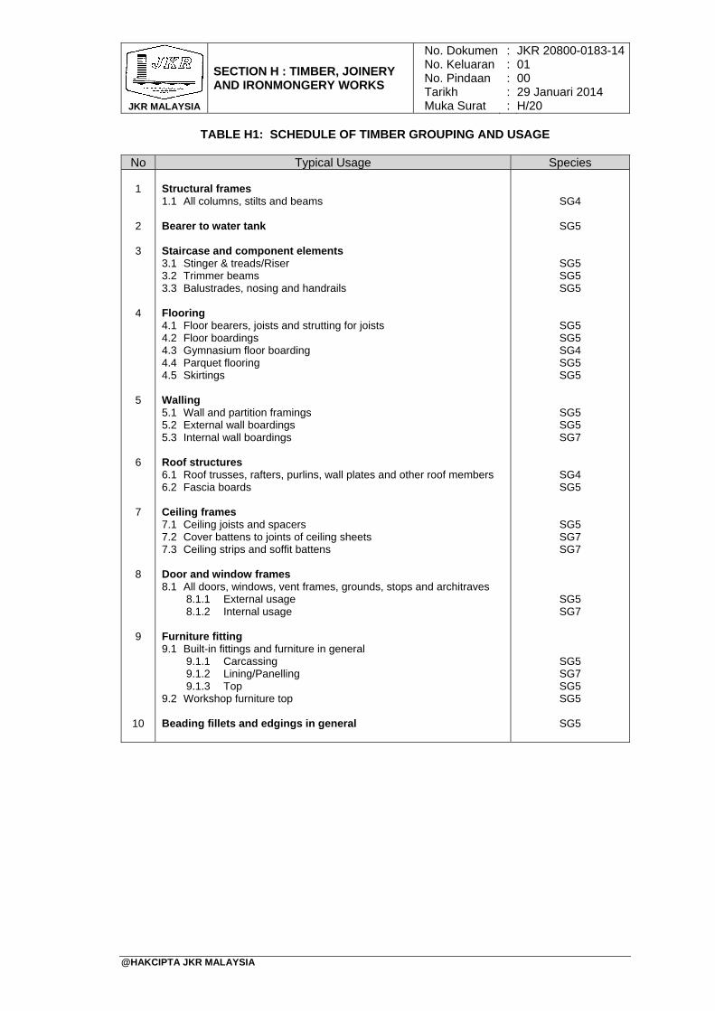
JKR MALAYSIA
SECTION H : TIMBER, JOINERY AND IRONMONGERY WORKS
No. DokumenNo. KeluaranNo. PindaanTarikhMuka Surat
: : : : :
JKR 20800-0183-1401 00 29 Januari 2014 H/20
@HAKCIPTA JKR MALAYSIA
TABLE H1: SCHEDULE OF TIMBER GROUPING AND USAGE
No Typical Usage Species 1 2 3 4 5 6 7 8 9
10
Structural frames 1.1 All columns, stilts and beams
Bearer to water tank Staircase and component elements 3.1 Stinger & treads/Riser 3.2 Trimmer beams 3.3 Balustrades, nosing and handrails Flooring 4.1 Floor bearers, joists and strutting for joists 4.2 Floor boardings 4.3 Gymnasium floor boarding 4.4 Parquet flooring 4.5 Skirtings
Walling 5.1 Wall and partition framings 5.2 External wall boardings 5.3 Internal wall boardings
Roof structures 6.1 Roof trusses, rafters, purlins, wall plates and other roof members 6.2 Fascia boards Ceiling frames 7.1 Ceiling joists and spacers 7.2 Cover battens to joints of ceiling sheets 7.3 Ceiling strips and soffit battens Door and window frames 8.1 All doors, windows, vent frames, grounds, stops and architraves
8.1.1 External usage 8.1.2 Internal usage
Furniture fitting 9.1 Built-in fittings and furniture in general
9.1.1 Carcassing 9.1.2 Lining/Panelling 9.1.3 Top
9.2 Workshop furniture top Beading fillets and edgings in general
SG4
SG5
SG5 SG5 SG5
SG5 SG5 SG4 SG5 SG5
SG5 SG5 SG7
SG4 SG5
SG5 SG7 SG7
SG5 SG7
SG5 SG7 SG5 SG5
SG5
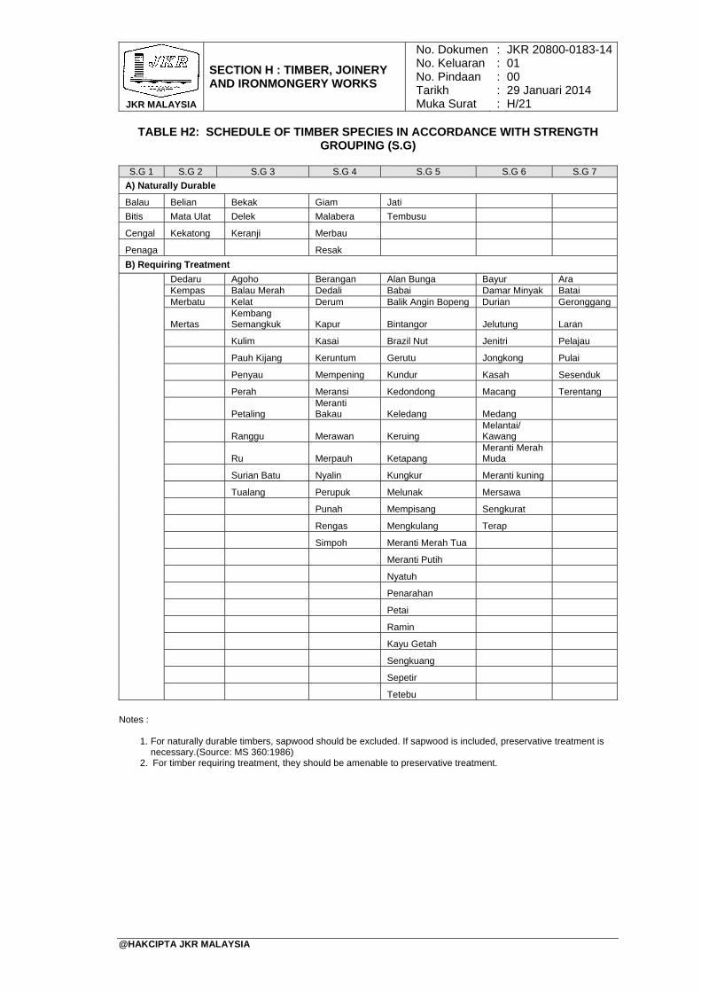
JKR MALAYSIA
SECTION H : TIMBER, JOINERY AND IRONMONGERY WORKS
No. DokumenNo. KeluaranNo. PindaanTarikhMuka Surat
: : : : :
JKR 20800-0183-1401 00 29 Januari 2014 H/21
@HAKCIPTA JKR MALAYSIA
TABLE H2: SCHEDULE OF TIMBER SPECIES IN ACCORDANCE WITH STRENGTH GROUPING (S.G)
S.G 1 S.G 2 S.G 3 S.G 4 S.G 5 S.G 6 S.G 7
A) Naturally Durable
Balau Belian Bekak Giam Jati Bitis Mata Ulat Delek Malabera Tembusu
Cengal Kekatong Keranji Merbau
Penaga Resak
B) Requiring Treatment
Dedaru Agoho Berangan Alan Bunga Bayur Ara Kempas Balau Merah Dedali Babai Damar Minyak Batai Merbatu Kelat Derum Balik Angin Bopeng Durian Geronggang
Mertas Kembang Semangkuk Kapur Bintangor Jelutung Laran
Kulim Kasai Brazil Nut Jenitri Pelajau
Pauh Kijang Keruntum Gerutu Jongkong Pulai
Penyau Mempening Kundur Kasah Sesenduk
Perah Meransi Kedondong Macang Terentang
Petaling
Meranti Bakau Keledang Medang
Ranggu Merawan Keruing
Melantai/ Kawang
Ru Merpauh Ketapang
Meranti Merah Muda
Surian Batu Nyalin Kungkur Meranti kuning
Tualang Perupuk Melunak Mersawa
Punah Mempisang Sengkurat
Rengas Mengkulang Terap
Simpoh Meranti Merah Tua
Meranti Putih
Nyatuh
Penarahan
Petai
Ramin
Kayu Getah
Sengkuang
Sepetir
Tetebu
Notes :
1. For naturally durable timbers, sapwood should be excluded. If sapwood is included, preservative treatment is
necessary.(Source: MS 360:1986) 2. For timber requiring treatment, they should be amenable to preservative treatment.
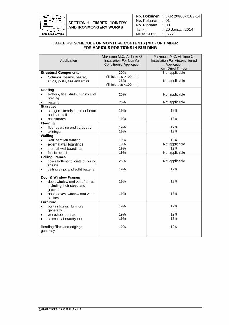
JKR MALAYSIA
SECTION H : TIMBER, JOINERY AND IRONMONGERY WORKS
No. DokumenNo. KeluaranNo. PindaanTarikhMuka Surat
: : : : :
JKR 20800-0183-1401 00 29 Januari 2014 H/22
@HAKCIPTA JKR MALAYSIA
TABLE H3: SCHEDULE OF MOISTURE CONTENTS (M.C) OF TIMBER FOR VARIOUS POSITIONS IN BUILDING
Application Maximum M.C. At Time Of
Installation For Non Air-Conditioned Application
Maximum M.C. At Time Of Installation For Airconditioned
Application (Kiln-Dried Timber)
Structural Components Columns, beams, bearer,
studs, joists, ties and struts
30% (Thickness >100mm)
25% (Thickness <100mm)
Not applicable
Not applicable
Roofing Rafters, ties, struts, purlins and
bracing
25%
Not applicable
battens 25% Not applicable Staircase stringers, treads, trimmer beam
and handrail
19%
12%
balustrades 19% 12% Flooring floor boarding and parquetry
19%
12%
skirtings 19% 12% Walling wall, partition framing
19%
12%
external wall boardings 19% Not applicable internal wall boardings 19% 12% fascia boards 19% Not applicable Ceiling Frames cover battens to joints of ceiling
sheets
25%
Not applicable
ceiling strips and soffit battens 19% 12% Door & Window Frames door, window and vent frames
including their stops and grounds
19%
12%
door leaves, window and vent sashes
19% 12%
Furniture built in fittings, furniture
generally
19%
12%
workshop furniture 19% 12% science laboratory tops 19% 12% Beading fillets and edgings generally
19%
12%
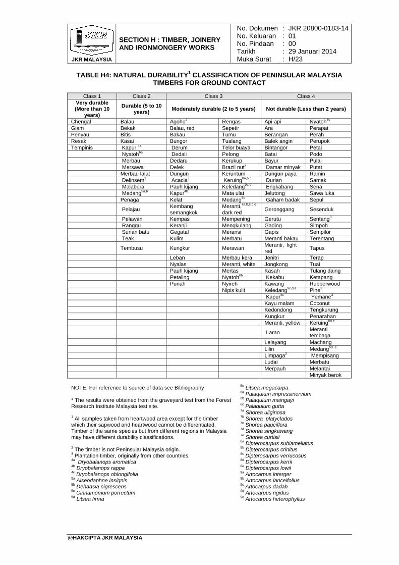
JKR MALAYSIA
SECTION H : TIMBER, JOINERY AND IRONMONGERY WORKS
No. DokumenNo. KeluaranNo. PindaanTarikhMuka Surat
: : : : :
JKR 20800-0183-1401 00 29 Januari 2014 H/23
@HAKCIPTA JKR MALAYSIA
TABLE H4: NATURAL DURABILITY1 CLASSIFICATION OF PENINSULAR MALAYSIA TIMBERS FOR GROUND CONTACT
Class 1 Class 2 Class 3 Class 4
Very durable (More than 10
years)
Durable (5 to 10 years)
Moderately durable (2 to 5 years) Not durable (Less than 2 years)
Chengal Balau Agoho2 Rengas Api-api Nyatoh6c Giam Bekak Balau, red Sepetir Ara Perapat Penyau Bitis Bakau Tumu Berangan Perah Resak Kasai Bungor Tualang Balek angin Perupok Tempinis Kapur 4a Derum Telor buaya Bintangor Petai Nyatoh6a Dedali Pelong Batai Podo Merbau Dedaru Kerukup Bayur Pulai Mersawa Delek Brazil nut2 Damar minyak Putat Merbau lalat Dungun Keruntum Dungun paya Ramin Delinsem2 Acacia3 Keruing8a,b,c Durian Samak Malabera Pauh kijang Keledang9a,b Engkabang Sena Medang5a,b Kapur4b Mata ulat Jelutong Sawa luka Penaga Kelat Medang5c Gaham badak Sepul
Pelajau Kembang semangkok
Meranti,7a,b,c,d,e dark red
Geronggang Sesenduk
Pelawan Kempas Mempening Gerutu Sentang3 Ranggu Keranji Mengkulang Gading Simpoh Surian batu Gegatal Meransi Gapis Sempilor Teak Kulim Merbatu Meranti bakau Terentang
Tembusu Kungkur Merawan Meranti, light red
Tapus
Leban Merbau kera Jenitri Terap Nyalas Meranti, white Jongkong Tuai Pauh kijang Mertas Kasah Tulang daing Petaling Nyatoh6b Kekabu Ketapang Punah Nyireh Kawang Rubberwood Nipis kulit Keledang9c,d,e Pine3 Kapur4c Yemane3 Kayu malam Coconut Kedondong Tengkurung Kungkur Penarahan Meranti, yellow Keruing8d,e
Laran Meranti tembaga
Lelayang Machang Lilin Medang5d, e Limpaga2 Mempisang Ludai Merbatu Merpauh Melantai Minyak berok
NOTE. For reference to source of data see Bibliography * The results were obtained from the graveyard test from the Forest Research Institute Malaysia test site. 1 All samples taken from heartwood area except for the timber which their sapwood and heartwood cannot be differentiated. Timber of the same species but from different regions in Malaysia may have different durability classifications. 2 The timber is not Peninsular Malaysia origin. 3 Plantation timber, originally from other countries. 4a Dryobalanops aromatica 4b Dryobalanops rappa 4c Dryobalanops oblongifolia 5a Alseodaphne insignis 5b Dehaasia nigrescens 5c Cinnamomum porrectum 5d Litsea firma
5e Litsea megacarpa 6a Palaquium impressinervium 6b Palaquium maingayi 6c Palaquium gutta 7a Shorea uliginosa 7b Shorea platyclados 7c Shorea pauciflora 7d Shorea singkawang 7e Shorea curtisii 8a Dipterocarpus sublamellatus 8b Dipterocarpus crinitus 8c Dipterocarpus verrucosus 8d Dipterocarpus kerrii 8e Dipterocarpus lowii 9a Artocarpus interger 9b Artocarpus lanceifolius 9c Artocarpus dadah 9d Artocarpus rigidus 9e Artocarpus heterophyllus
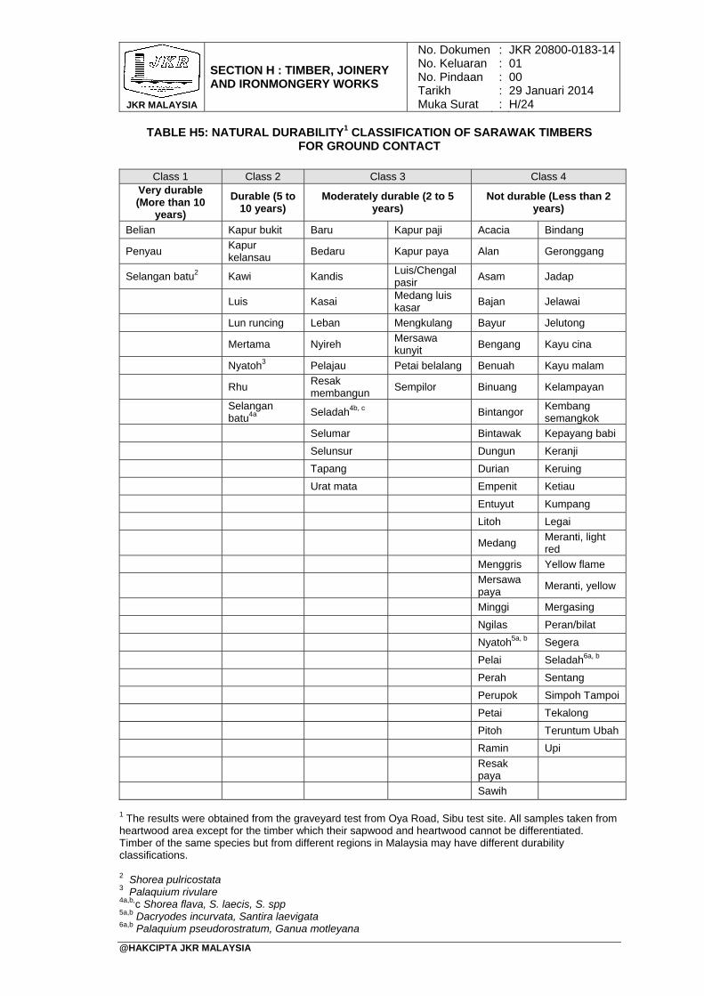
JKR MALAYSIA
SECTION H : TIMBER, JOINERY AND IRONMONGERY WORKS
No. DokumenNo. KeluaranNo. PindaanTarikhMuka Surat
: : : : :
JKR 20800-0183-1401 00 29 Januari 2014 H/24
@HAKCIPTA JKR MALAYSIA
TABLE H5: NATURAL DURABILITY1 CLASSIFICATION OF SARAWAK TIMBERS FOR GROUND CONTACT
Class 1 Class 2 Class 3 Class 4
Very durable (More than 10
years)
Durable (5 to 10 years)
Moderately durable (2 to 5 years)
Not durable (Less than 2 years)
Belian Kapur bukit Baru Kapur paji Acacia Bindang
Penyau Kapur kelansau
Bedaru Kapur paya Alan Geronggang
Selangan batu2 Kawi Kandis Luis/Chengal pasir
Asam Jadap
Luis Kasai Medang luis kasar
Bajan Jelawai
Lun runcing Leban Mengkulang Bayur Jelutong
Mertama Nyireh Mersawa kunyit
Bengang Kayu cina
Nyatoh3 Pelajau Petai belalang Benuah Kayu malam
Rhu Resak membangun
Sempilor Binuang Kelampayan
Selangan batu4a
Seladah4b, c Bintangor Kembang semangkok
Selumar Bintawak Kepayang babi
Selunsur Dungun Keranji
Tapang Durian Keruing
Urat mata Empenit Ketiau
Entuyut Kumpang
Litoh Legai
Medang Meranti, light red
Menggris Yellow flame
Mersawa paya
Meranti, yellow
Minggi Mergasing
Ngilas Peran/bilat
Nyatoh5a, b Segera
Pelai Seladah6a, b
Perah Sentang
Perupok Simpoh Tampoi
Petai Tekalong
Pitoh Teruntum Ubah
Ramin Upi
Resak paya
Sawih
1 The results were obtained from the graveyard test from Oya Road, Sibu test site. All samples taken from heartwood area except for the timber which their sapwood and heartwood cannot be differentiated. Timber of the same species but from different regions in Malaysia may have different durability classifications. 2 Shorea pulricostata 3 Palaquium rivulare 4a,b,c Shorea flava, S. laecis, S. spp 5a,b Dacryodes incurvata, Santira laevigata 6a,b Palaquium pseudorostratum, Ganua motleyana
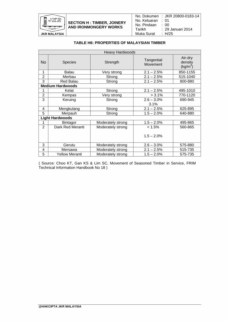
JKR MALAYSIA
SECTION H : TIMBER, JOINERY AND IRONMONGERY WORKS
No. DokumenNo. KeluaranNo. PindaanTarikhMuka Surat
: : : : :
JKR 20800-0183-1401 00 29 Januari 2014 H/25
@HAKCIPTA JKR MALAYSIA
TABLE H6: PROPERTIES OF MALAYSIAN TIMBER
Heavy Hardwoods
No Species Strength Tangential Movement
Air-dry density (kg/m3)
1 Balau Very strong 2.1 – 2.5% 850-1155 2 Merbau Strong 2.1 – 2.5% 515-1040 3 Red Balau Strong 2.1 – 2.5% 800-880
Medium Hardwoods 1 Kelat Strong 2.1 – 2.5% 495-1010 2 Kempas Very strong > 3.1% 770-1120 3 Keruing Strong 2.6 – 3.0%
3.1% 690-945
4 Mengkulang Strong 2.1 – 2.5% 625-895 5 Merpauh Strong 1.5 – 2.0% 640-880
Light Hardwoods 1 Bintagor Moderately strong 1.5 – 2.0% 495-865 2 Dark Red Meranti Moderately strong < 1.5%
1.5 – 2.0%
560-865
3 Gerutu Moderately strong 2.6 – 3.0% 575-880 4 Mersawa Moderately strong 2.1 – 2.5% 515-735 5 Yellow Meranti Moderately strong 1.5 – 2.0% 575-735
( Source: Choo KT, Gan KS & Lim SC, Movement of Seasoned Timber in Service, FRIM Technical Information Handbook No 18 )
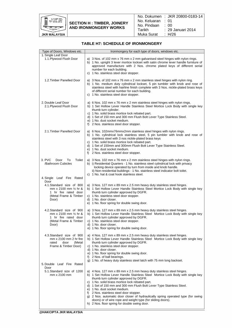
JKR MALAYSIA
SECTION H : TIMBER, JOINERY AND IRONMONGERY WORKS
No. DokumenNo. KeluaranNo. PindaanTarikhMuka Surat
: : : : :
JKR 20800-0183-1401 00 29 Januari 2014 H/26
@HAKCIPTA JKR MALAYSIA
TABLE H7: SCHEDULE OF IRONMONGERY
Type of Doors, Windows etc. Ironmongery for each type of doors, windows etc. 1. Single Leaf Door
1.1. Plywood Flush Door a) 3 Nos. of 102 mm x 76 mm x 2 mm galvanised steel hinges with nylon rings. b) 1 No. upright 3 lever mortice lockset with satin chrome lever handle furniture of
approved manufacture with 2 Nos. chrome plated keys of different serial number for each building.
c) 1 No. stainless steel door stopper.
1.2. Timber Panelled Door a) 3 Nos. of 102 mm x 76 mm x 2 mm stainless steel hinges with nylon ring. b) 1 No. medium duty cylindrical lockset, 5 pin tumbler with knob and rose of
stainless steel with hairline finish complete with 3 Nos. nickle-plated brass keys of different serial number for each building.
c) 1 No. stainless steel door stopper.
2. Double Leaf Door
2.1. Plywood Flush Door a) 6 Nos. 102 mm x 76 mm x 2 mm stainless steel hinges with nylon rings. b) 1 Set Hollow Lever Handle Stainless Steel Mortice Lock Body with single key
thumb turn cylinder. c) 1 No. solid brass mortice lock rebated part. d) 1 Set of 150 mm and 300 mm Flush Bolt Lever Type Stainless Steel. e) 1 No. dust socket medium. f) 2 Nos. stainless steel door stopper.
2.1. Timber Panelled Door a) 6 Nos. 102mmx76mmx2mm stainless steel hinges with nylon rings. b) 1 No. cylindrical lock stainless steel, 5 pin tumbler with knob and rose of
stainless steel with 3 nos nickle-plated brass keys c) 1 No. solid brass mortice lock rebated part. d) 1 Set of 150mm and 300mm Flush Bolt Lever Type Stainless Steel. e) 1 No. dust socket medium. f) 2 Nos. stainless steel door stopper.
3. PVC Door To Toilet /Bathroom Cubicles
a) 3 Nos. 102 mm x 76 mm x 2 mm stainless steel hinges with nylon rings. b) i) Residential Quarters - 1 No. stainless steel cylindrical lock with privacy locking device operated by turn from inside and knob handle.
ii) Non-residential buildings - 1 No. stainless steel indicator bolt toilet. c) 1 No. hat & coat hook stainless steel.
4. Single Leaf Fire Rated Door
4.1. Standard size of 800 mm x 2100 mm ½ hr & 1 hr fire rated door (Metal Frame & Timber Door)
a) 3 Nos. 127 mm x 89 mm x 2.5 mm heavy duty stainless steel hinges. b) 1 Set Hollow Lever Handle Stainless Steel Mortice Lock Body with single key
thumb turn cylinder approved by DGFR. c) 1 No. stainless steel door stopper. d) 1 No. door closer. e) 1 No. floor spring for double swing door.
4.2. Standard size of 900 mm x 2100 mm ½ hr & 1 hr fire rated door (Metal Frame & Timber Door)
a) 3 Nos. 127 mm x 89 mm x 2.5 mm heavy duty stainless steel hinges. b) 1 Set Hollow Lever Handle Stainless Steel Mortice Lock Body with single key
thumb turn cylinder approved by DGFR. c) 1 No. stainless steel door stopper. d) 1 No. door closer. e) 1 No. floor spring for double swing door.
4.3. Standard size of 900 mm x 2100 mm 2 hr fire rated door (Metal Frame & Timber Door)
a) 4 Nos. 127 mm x 89 mm x 2.5 mm heavy duty stainless steel hinges. b) 1 Set Hollow Lever Handle Stainless Steel Mortice Lock Body with single key
thumb turn cylinder approved by DGFR. c) 1 No. stainless steel door stopper. d) 1 No. door closer. e) 1 No. floor spring for double swing door. f) 2 Nos. of ball bearings. g) 1 No. of heavy duty stainless steel latch with 75 mm long backset.
5. Double Leaf Fire Rated Door
5.1. Standard size of 1200 mm x 2100 mm
a) 4 Nos. 127 mm x 89 mm x 2.5 mm heavy duty stainless steel hinges. b) 1 Set Hollow Lever Handle Stainless Steel Mortice Lock Body with single key
thumb turn cylinder approved by DGFR. c) 1 No. solid brass mortice lock rebated part. d) 1 Set of 150 mm and 300 mm Flush Bolt Lever Type Stainless Steel. e) 1 No. dust socket medium. f) 2 Nos. stainless steel door stopper. g) 2 Nos. automatic door closer of hydraulically spring operated type (for swing
doors) or of wire rope and weight type (for sliding doors). h) 2 Nos. floor spring for double swing door.
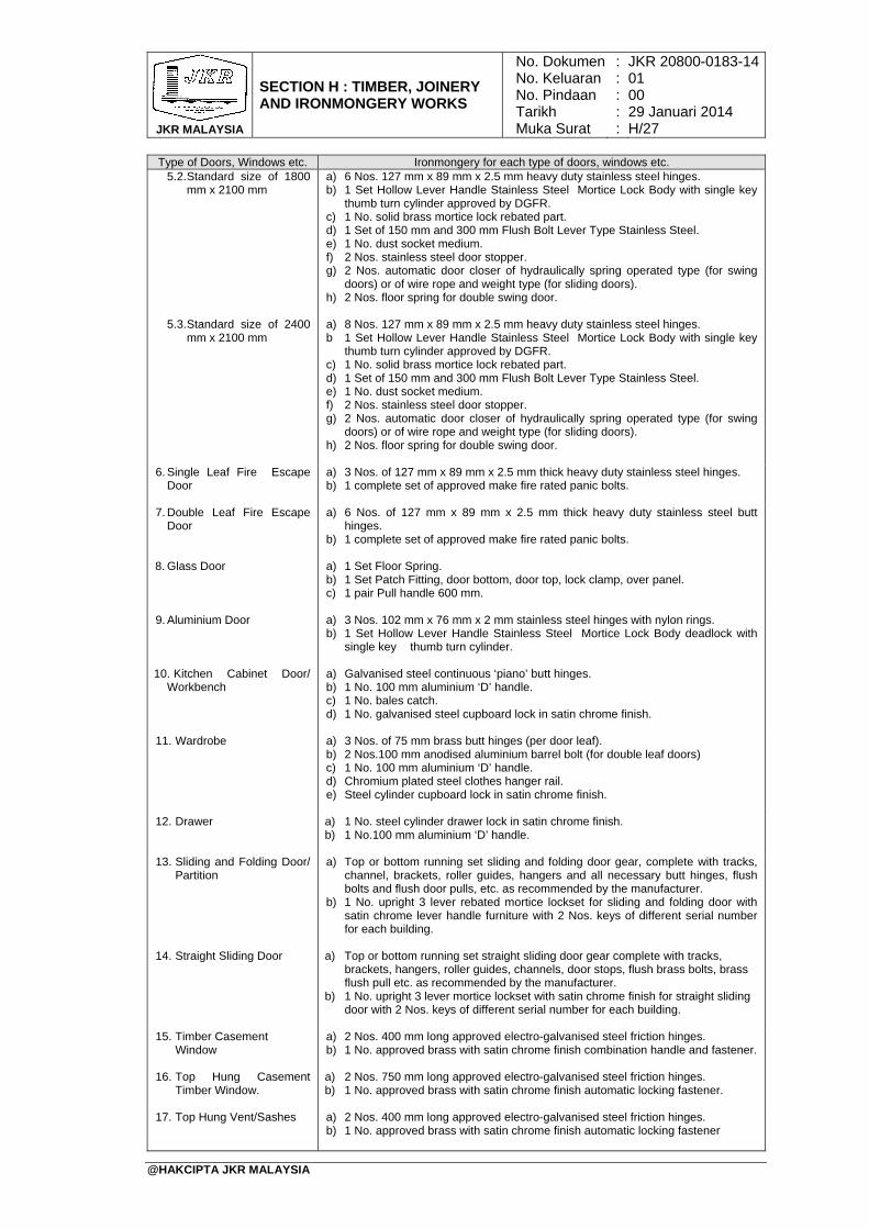
JKR MALAYSIA
SECTION H : TIMBER, JOINERY AND IRONMONGERY WORKS
No. DokumenNo. KeluaranNo. PindaanTarikhMuka Surat
: : : : :
JKR 20800-0183-1401 00 29 Januari 2014 H/27
@HAKCIPTA JKR MALAYSIA
Type of Doors, Windows etc. Ironmongery for each type of doors, windows etc. 5.2. Standard size of 1800
mm x 2100 mm a) 6 Nos. 127 mm x 89 mm x 2.5 mm heavy duty stainless steel hinges. b) 1 Set Hollow Lever Handle Stainless Steel Mortice Lock Body with single key
thumb turn cylinder approved by DGFR. c) 1 No. solid brass mortice lock rebated part. d) 1 Set of 150 mm and 300 mm Flush Bolt Lever Type Stainless Steel. e) 1 No. dust socket medium. f) 2 Nos. stainless steel door stopper. g) 2 Nos. automatic door closer of hydraulically spring operated type (for swing
doors) or of wire rope and weight type (for sliding doors). h) 2 Nos. floor spring for double swing door.
5.3. Standard size of 2400 mm x 2100 mm
a) 8 Nos. 127 mm x 89 mm x 2.5 mm heavy duty stainless steel hinges. b 1 Set Hollow Lever Handle Stainless Steel Mortice Lock Body with single key
thumb turn cylinder approved by DGFR. c) 1 No. solid brass mortice lock rebated part. d) 1 Set of 150 mm and 300 mm Flush Bolt Lever Type Stainless Steel. e) 1 No. dust socket medium. f) 2 Nos. stainless steel door stopper. g) 2 Nos. automatic door closer of hydraulically spring operated type (for swing
doors) or of wire rope and weight type (for sliding doors). h) 2 Nos. floor spring for double swing door.
6. Single Leaf Fire Escape Door
a) 3 Nos. of 127 mm x 89 mm x 2.5 mm thick heavy duty stainless steel hinges. b) 1 complete set of approved make fire rated panic bolts.
7. Double Leaf Fire Escape Door
a) 6 Nos. of 127 mm x 89 mm x 2.5 mm thick heavy duty stainless steel butt hinges.
b) 1 complete set of approved make fire rated panic bolts.
8. Glass Door a) 1 Set Floor Spring. b) 1 Set Patch Fitting, door bottom, door top, lock clamp, over panel. c) 1 pair Pull handle 600 mm.
9. Aluminium Door a) 3 Nos. 102 mm x 76 mm x 2 mm stainless steel hinges with nylon rings. b) 1 Set Hollow Lever Handle Stainless Steel Mortice Lock Body deadlock with
single key thumb turn cylinder.
10. Kitchen Cabinet Door/ Workbench
a) Galvanised steel continuous ‘piano’ butt hinges. b) 1 No. 100 mm aluminium ‘D’ handle. c) 1 No. bales catch. d) 1 No. galvanised steel cupboard lock in satin chrome finish.
11. Wardrobe a) 3 Nos. of 75 mm brass butt hinges (per door leaf).
b) 2 Nos.100 mm anodised aluminium barrel bolt (for double leaf doors) c) 1 No. 100 mm aluminium ‘D’ handle. d) Chromium plated steel clothes hanger rail. e) Steel cylinder cupboard lock in satin chrome finish.
12. Drawer a) 1 No. steel cylinder drawer lock in satin chrome finish. b) 1 No.100 mm aluminium ‘D’ handle.
13. Sliding and Folding Door/ Partition
a) Top or bottom running set sliding and folding door gear, complete with tracks, channel, brackets, roller guides, hangers and all necessary butt hinges, flush bolts and flush door pulls, etc. as recommended by the manufacturer.
b) 1 No. upright 3 lever rebated mortice lockset for sliding and folding door with satin chrome lever handle furniture with 2 Nos. keys of different serial number for each building.
14. Straight Sliding Door a) Top or bottom running set straight sliding door gear complete with tracks,
brackets, hangers, roller guides, channels, door stops, flush brass bolts, brass flush pull etc. as recommended by the manufacturer.
b) 1 No. upright 3 lever mortice lockset with satin chrome finish for straight sliding door with 2 Nos. keys of different serial number for each building.
15. Timber Casement
Window a) 2 Nos. 400 mm long approved electro-galvanised steel friction hinges. b) 1 No. approved brass with satin chrome finish combination handle and fastener.
16. Top Hung Casement
Timber Window. a) 2 Nos. 750 mm long approved electro-galvanised steel friction hinges. b) 1 No. approved brass with satin chrome finish automatic locking fastener.
17. Top Hung Vent/Sashes a) 2 Nos. 400 mm long approved electro-galvanised steel friction hinges.
b) 1 No. approved brass with satin chrome finish automatic locking fastener
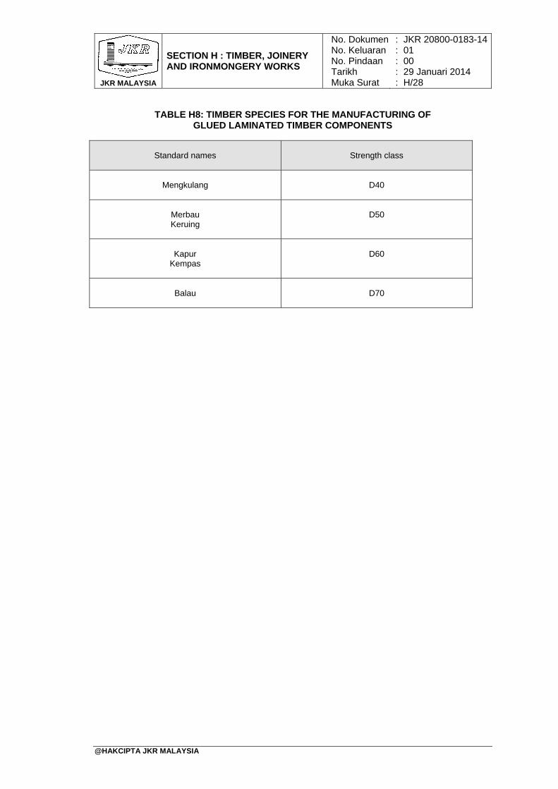
JKR MALAYSIA
SECTION H : TIMBER, JOINERY AND IRONMONGERY WORKS
No. DokumenNo. KeluaranNo. PindaanTarikhMuka Surat
: : : : :
JKR 20800-0183-1401 00 29 Januari 2014 H/28
@HAKCIPTA JKR MALAYSIA
TABLE H8: TIMBER SPECIES FOR THE MANUFACTURING OF
GLUED LAMINATED TIMBER COMPONENTS
Standard names
Strength class
Mengkulang
D40
Merbau Keruing
D50
Kapur
Kempas
D60
Balau
D70
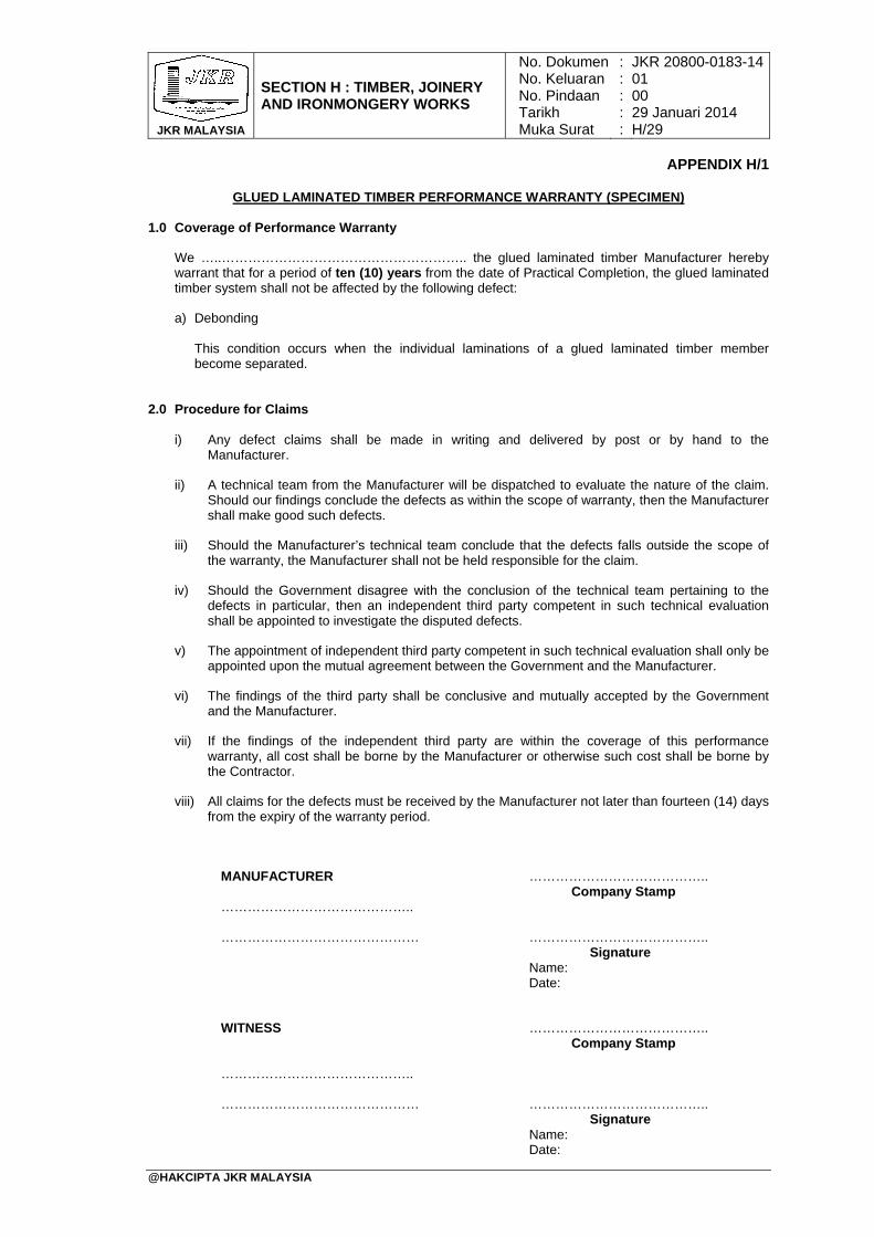
JKR MALAYSIA
SECTION H : TIMBER, JOINERY AND IRONMONGERY WORKS
No. DokumenNo. KeluaranNo. PindaanTarikhMuka Surat
: : : : :
JKR 20800-0183-1401 00 29 Januari 2014 H/29
@HAKCIPTA JKR MALAYSIA
APPENDIX H/1
GLUED LAMINATED TIMBER PERFORMANCE WARRANTY (SPECIMEN)
1.0 Coverage of Performance Warranty
We …..……………………………………………….. the glued laminated timber Manufacturer hereby warrant that for a period of ten (10) years from the date of Practical Completion, the glued laminated timber system shall not be affected by the following defect:
a) Debonding
This condition occurs when the individual laminations of a glued laminated timber member become separated.
2.0 Procedure for Claims
i) Any defect claims shall be made in writing and delivered by post or by hand to the Manufacturer.
ii) A technical team from the Manufacturer will be dispatched to evaluate the nature of the claim. Should our findings conclude the defects as within the scope of warranty, then the Manufacturer shall make good such defects.
iii) Should the Manufacturer’s technical team conclude that the defects falls outside the scope of the warranty, the Manufacturer shall not be held responsible for the claim.
iv) Should the Government disagree with the conclusion of the technical team pertaining to the defects in particular, then an independent third party competent in such technical evaluation shall be appointed to investigate the disputed defects.
v) The appointment of independent third party competent in such technical evaluation shall only be appointed upon the mutual agreement between the Government and the Manufacturer.
vi) The findings of the third party shall be conclusive and mutually accepted by the Government and the Manufacturer.
vii) If the findings of the independent third party are within the coverage of this performance warranty, all cost shall be borne by the Manufacturer or otherwise such cost shall be borne by the Contractor.
viii) All claims for the defects must be received by the Manufacturer not later than fourteen (14) days from the expiry of the warranty period.
MANUFACTURER ………………………………….. Company Stamp …………………………………….. ……………………………………… ………………………………….. Signature Name: Date:
WITNESS ………………………………….. Company Stamp …………………………………….. ……………………………………… ………………………………….. Signature Name: Date:

JKR MALAYSIA
SECTION H : TIMBER, JOINERY AND IRONMONGERY WORKS
No. DokumenNo. KeluaranNo. PindaanTarikhMuka Surat
: : : : :
JKR 20800-0183-1401 00 29 Januari 2014 H/30
@HAKCIPTA JKR MALAYSIA
BLANK PAGE
TABLE OF CONTENTS
SECTION I: CEILING WORKS
PAGE
@HAKCIPTA JKR MALAYSIA
1. General 2. Submittals 3. Setting Out 4. Acoustic Requirements 5. Materials And Ceiling Components 6. Ceiling Suspension System
I/1 I/1 I/1 I/2 I/2 I/5


JKR MALAYSIA
SECTION I : CEILING WORKS
No. DokumenNo. KeluaranNo. PindaanTarikhMuka Surat
: : : : :
JKR 20800-0183-1401 00 29 Januari 2014 I/1
@HAKCIPTA JKR MALAYSIA
1. General 1.1 Unless otherwise specified or shown on the Drawings, all ceilings shall be Mineral
Fiber Boards or as approved by the S.O. with class ‘O’ fire rating and all ceiling installation shall comply with the classification of fire spread as stipulated in the 8th Schedule Uniform Building By-Law 1984.
1.2 All ceilings shall be provided with service access to the ceiling void for maintenance of services above the ceiling space in accordance to the Drawings and approval of the S.O.
1.3 All sprinkler heads (drops) shall have 12.5 mm diameter oversize ring, sleeve or adaptor through the ceiling tile to allow for free movement of the sprinkler pipes. It shall also comply with the local fire regulations and to the S.O’s approval.
1.4 The Contractor shall not commence the ceiling installation works until the building is effectively weather-tight and the work area of wet trades has been completed and dried.
2. Submittals 2.1 Unless otherwise specified, the Contractor shall submit shop drawings and design
calculations for the complete proprietary ceiling system showing compliance to all specifications including the method of installation of the ceiling board/panels, hangers, fittings and all accessories duly certified by a P.E. registered with the Board of Engineers Malaysia.
2.2 The Contractor shall also submit floor plans showing the proposed location of the
anchors prior to the casting of the floor slab for the approval of the S.O. The plans shall be endorsed by the P.E.
2.3 No installation of ceiling works shall commence until approval is given in writing by
the S.O. 3. Setting Out
3.1 The ceiling layout shall be planned prior to installation to determine the grid
configuration, direction et cetera to ensure that all fixings points are compatible with the structural members or other services, or both.
3.2 Mechanical and electrical services shall be completed before installation of the suspension systems. Down-lights or other services shall not rely on the ceiling panel for support. Suspension hangers may be installed before or during installation of services with the approval of the S.O.
3.3 The shop drawings used for the ceiling installation shall contain sufficient information to allow the installer to set out the ceiling grid. The finished height of the ceiling shall be shown clearly on the drawings.
3.4 Sufficient information should be clearly indicated on the drawings to enable the ceiling module and setting out points in each ceiling area applicable to all relevant trades to be established early. All trades shall work to the same setting out points and data.
3.5 The ceiling height in each area shall be marked in relation to the elevation benchmarks and then transferred by means of a water level, rotating laser or other
JKR MALAYSIA
SECTION I : CEILING WORKS
No. DokumenNo. KeluaranNo. PindaanTarikhMuka Surat
: : : : :
JKR 20800-0183-1401 00 29 Januari 2014 I/2
@HAKCIPTA JKR MALAYSIA
approved devices. Setting out lines should be in both directions and squared accurately at the outset.
4. Acoustic Requirements 4.1 Acoustic requirements specified or shown on the Drawings, such as sound
absorption, sound insulation and impact sound insulation shall be tested in accordance with BS EN 13964, BS EN ISO 140 or other acceptable standards.
4.2 A full test report shall be submitted to the S.O as proof of compliance. It shall relate to the entire specified system. Any variations shall be endorsed by the test laboratory or field testing. Test reports, comments and the testing authority shall be stated in the manufacturer’s trade literature or be made available upon request or both.
5. Materials And Ceiling Components 5.1 Zinc-Coated And Aluminium/Zinc Coated Steel
Zinc-coated and aluminum/zinc-coated steel used for the construction of suspended ceiling components shall comply with MS 1196 or other equivalent Standards. The Contractor shall provide proof of compliance to the approval of the S.O. Where sections have been cut from zinc-coated or aluminium/zinc-coated sheets, the cut edges shall be treated with protective anti-rust paint to prevent corrosion. All pre-painted finish for ceilings shall be as specified under SECTION G: ROOFING WORKS.
5.2 Linear Strip Ceiling Unless otherwise specified or shown on the Drawings, linear strip ceiling shall be aluminium pre-painted anodized comprising of 150mm width x 12.5mm deep x 0.6mm thick panel fixed in accordance to manufacturer’s recommendation and to S.O’s approval.
5.3 Plasterboard 5.3.1 All plasterboards dimensions, its tolerances and flexural breaking load shall
comply with BS EN 520. The board shall carry class 'O' approval from DGFR.
5.3.2 Unless otherwise specified in the Drawings the size for plasterboard ceiling shall be 600 mm x 1200 mm x 9 mm thick minimum and shall be suspended from the soffit with adjustable hanger rods in accordance to manufacturer’s recommendation and S.O’s approval.
5.4 Plasterboard With Improved Core Adhesion At High Temperature (Type F) The type of board and test requirements shall be in accordance with BS EN 520, and to the approval of the S.O. The board shall carry Class 'O' approval from DGFR.
5.5 Plasterboard With Reduced Water Absorption (Type H) The types of moisture resistance board to receive paint finish shall be in accordance with BS EN 520 and to the approval of the S.O. The board shall carry Class 'O' approval from DGFR.
JKR MALAYSIA
SECTION I : CEILING WORKS
No. DokumenNo. KeluaranNo. PindaanTarikhMuka Surat
: : : : :
JKR 20800-0183-1401 00 29 Januari 2014 I/3
@HAKCIPTA JKR MALAYSIA
5.6 Mineral Fibre Boards 5.6.1 Unless otherwise specified, the board size shall be 600 mm x 1200 mm x
15 mm thick square edges. The board shall carry Class 'O' approval from the DGFR and the minimum sag resistance shall be of RH 99.
5.6.2 Surface coating of the board shall be applied with vinyl latex paint in white colour at factory and the surface design of the board shall be to S.O.’s approval.
5.7 Fibre Cement Ceiling Panel Fibre cement ceiling panel shall be asbestos free and shall be an autoclaved cellulose fibre cement flat board. The basic composition consists of cement, refined sand and cellulose fiber. The material shall be classified as Class ‘O’ and shall be ‘Fire- Listed’ under SIRIM QAS Fire Listing Scheme.
5.8 Acoustic Glass Wool Ceiling Panel Acoustic glass wool ceiling panel shall be lightweight fibre glass wool material with high acoustical sound absorption of NRC: 0.90-1.00 (ASTMC 423). Unless otherwise specified the size of the panel shall be 600 mm x 1200 mm x 20 mm thick, square edge fixed to aluminium tee exposed grid systems, suspended from the soffit with adjustable hanger rods in accordance to manufacturer’s recommendation and S.O’s approval.
5.9 Glass Fibre Reinforced Gypsum (GRG) 5.9.1 GRG Boards are manufactured by glass fibre reinforced gypsum and
comprise of non-combustible high grade gypsum casting plaster with glass fibre membranes. Unless otherwise specified shall be in sizes of 1200 mm X 900 mm x 9 mm thick. The board shall conform to the following:
Fire performance : GRG Boards are rated non-combustible as defined in BS 476: Part 4.
Dry Density : Approx. 1660 kg/m²
5.9.2 GRG boards shall be installed in accordance to the manufacturer’s recommendation and to S.O’s approval.
5.10 Cornice 5.10.1 Unless otherwise specified, cornice shall be provided of the same ceiling
material for all plaster ceiling materials.
5.10.2 Cornice shall be fixed to the walls and ceiling using proprietary adhesive or as recommended by the manufacturer and approved by the S.O.
5.10.3 Large cornices shall be fixed using screws together with cornice adhesive as recommended by the cornice manufacturer and to SO’s approval.
5.10.4 Cornice should be carried and handled carefully to avoid cracking the core or wrinkling the paper liner. Where possible, the contractor shall use full lengths of cornice and mitre all joints.
5.10.5 The Contractor shall ensure accurate and level placement by marking ceilings and walls with a line at the cornice edge.
JKR MALAYSIA
SECTION I : CEILING WORKS
No. DokumenNo. KeluaranNo. PindaanTarikhMuka Surat
: : : : :
JKR 20800-0183-1401 00 29 Januari 2014 I/4
@HAKCIPTA JKR MALAYSIA
5.10.6 Cornice with shorter length shall be installed first followed by the longer lengths by bowing out to spring mitres fit into place.
5.11 Reinforcing/Jointing Tape The tape shall not be less than 50 mm wide perforated paper tape in accordance with ASTM C475 from an approved manufacturer, and to the approval of the S.O.
5.12 Jointing Compound Jointing compound shall be pre-mixed multi-purpose gypsum based air drying type compound, in accordance with BS EN 13963 and to the approval of the S.O.
5.13 Sealants Fire sealant for plasterboard with improved core adhesion at high temperature (Type F) and wet area sealant for plasterboard with reduced water absorption (Type H) shall be in accordance with BS 8212 and to the approval of the S.O. The appropriate type of sealant shall be used for the required type of plasterboard. Elastomeric sealants can be used at the perimeter of the dry lining or partitioning to provide an airtight construction and to the approval of the S.O.
5.14 Control Joint Unless otherwise specified, control joints shall be provided in a long continuous runs of ceiling, spaced at not more than 9 m centers maximum and recommended by the manufacturer and to the approval of the S.O.
5.15 Anchors And Fasteners 5.15.1 Anchors to be used throughout the work shall be of Grade 4.6 black
hexagon bolt and nut as specified in BS 4190: ISO Metric Black Hexagon Bolts, Screws and Nuts.
5.15.2 Where proprietary anchor is allowed to be proposed as alternative, the Contractor shall submit the details of the proposed anchor to the S.O for approval.
5.15.3 Notwithstanding the above, the alternative anchor proposed shall be made
of carbon steel galvanized to minimum thickness of 5 μm or stainless steel in accordance to European Technical Approval Guideline ETAG 001 Metal Anchors for Use in Concrete.
5.15.4 The size of the alternative anchor shall not be less than 6 mm diameter (M6) with effective anchorage depth of not less than 26 mm measured from the soffit of the floor slab. The hole for the anchor shall be drilled using drill bit of nominal diameter 6 mm. The design resistance in all load directions shall not be more than 1.10 kN.
5.15.5 Shot-fired alternative anchors shall not be allowed. Shot-fired hybrid-pin alternative anchors shall not be used to install the suspended ceiling hangers to the concrete soffit.
5.15.6 Fasteners shall have a corrosion-resistant finish and be appropriate for intended use, in accordance with BS EN 14566. The heads of fasteners shall be shaped so that they can be driven slightly below the surface of the plasterboard without punching through the paper liner.
JKR MALAYSIA
SECTION I : CEILING WORKS
No. DokumenNo. KeluaranNo. PindaanTarikhMuka Surat
: : : : :
JKR 20800-0183-1401 00 29 Januari 2014 I/5
@HAKCIPTA JKR MALAYSIA
6. Ceiling Suspension System 6.1 General
The Contractor shall provide 12 mm diameter Grade 4.6 black hexagon bolt and nut as specified in BS 4190: ISO Metric Black Hexagon Bolts, Screws and Nuts as anchors. The anchors shall be installed in the concrete slab during the casting of the floor at depth of not less than 75 mm measured from the soffit of the floor or as otherwise specified in the drawing.
6.2 Timber Fixed System 6.2.1 All timber materials used shall be treated and as specified under SECTION
H: Timber, Joinery & Ironmongery Works. Ceiling boards shall be fixed to the frames with butt ‘V’ joint using nails or screws as recommended by the ceiling manufacturer and to S.O’s approval.
6.2.2 All external ceiling shall be painted with weather resistant paint as specified under SECTION O: PAINTING WORKS.
6.3 Grid Ceiling Suspension System 6.3.1 Vertical suspension members
6.3.1.1 Ceiling hangers shall be galvanized mild steel suspension rods
of minimum 4 mm diameter consisting of 2 pieces held together by a rod joiner (adjustable type galvanized suspension clips).
6.3.1.2 One end of the hanger shall be attached to a pre-drilled galvanized mild steel z-shaped soffit cleat 25 mm x 50 mm x 25 mm with minimum base metal thickness of 2 mm. The mild steel soffit cleat shall be fixed to the black hexagon anchor. The other end of the hanger shall be secured using proprietary locking clips to the primary T-section. The T-sections shall be fixed accordingly to the required ceiling level by adjusting the length of the ceiling hanger through the rod joiner.
6.3.1.3 Where black hexagon anchors cast in the soffit of the floor slab are not provided, pre-drilled galvanized mild steel z-shaped soffit cleat 25 mm x 50 mm x 25 mm with minimum base metal thickness of 2 mm shall be provided. The mild steel soffit cleat shall be fixed by drilling and inserting M6 x 30 mm zinc plated proprietary alternative anchor to the structural soffit at a distance 200 mm away from the wall and then spaced equal to or not more than 1200 mm centre to centre (c/c) to form the grid of the ceiling hanger.
6.3.1.4 One end of the ceiling hanger shall be connected by bolt and nut to the pre-drilled soffit cleat and the other end of the hanger shall be secured to the primary T-section using proprietary locking clips.
6.3.2 Horizontal suspension members Perimeter wall angles shall be securely fixed to the adjacent perimeter walls using appropriate fixings forming part of the grid ceiling system as recommended by the manufacturer and approved by the S.O.
JKR MALAYSIA
SECTION I : CEILING WORKS
No. DokumenNo. KeluaranNo. PindaanTarikhMuka Surat
: : : : :
JKR 20800-0183-1401 00 29 Januari 2014 I/6
@HAKCIPTA JKR MALAYSIA
6.4 Concealed Ceiling Suspension System (Soffit-ceiling Distance < 1800 mm) Where shown on the Drawings or when the distance between the concrete soffit and the suspended ceiling board is less than 1800 mm in vertical height, the concealed ceiling suspension system shall be as follows: 6.4.1 Vertical suspension members
6.4.1.1 Ceiling hangers shall be galvanized mild steel 25 mm x 25 mm
angle section with 0.5 mm base metal thickness or galvanized mild steel suspension rods of minimum 4 mm diameter.
6.4.1.2 One end of the hanger shall be attached to a pre-drilled galvanized mild steel z-shaped soffit cleat 25 mm x 50 mm x 25 mm with minimum base metal thickness of 2 mm. The mild steel soffit cleat shall be fixed to the black hexagon anchor. The other end of the hanger shall be secured using proprietary locking clips or suspension brackets to the primary channel.
6.4.1.3 Where black hexagon anchors cast in the soffit of the floor slab are not provided, pre-drilled galvanized mild steel z-shaped soffit cleat 25 mm x 50 mm x 25 mm with minimum base metal thickness of 2 mm shall be provided. The mild steel soffit cleat shall be fixed by drilling and inserting M6 x 30 mm zinc plated proprietary alternative anchor to the structural soffit at a distance 100 mm away from the wall and then spaced equal to or not more than 1000 mm c/c to form the grid of the ceiling hanger.
6.4.1.4 One end of the ceiling hanger shall be connected by bolt and nut to the pre-drilled soffit cleat and the other end of the hanger shall be secured using proprietary locking clips or suspension brackets to the primary channel.
6.4.2 Horizontal suspension members 6.4.2.1 Primary rigidized channel shall be 34 mm x 12 mm x 0.4 BMT
at a distance of 100 mm away from the wall and spaced equal to or not more than 1000 mm c/c. and secured to the rigidized galvanized steel ceiling hangers using wafer head drywall screw M4.2 x13 mm length as recommended by the manufacturer and to the approval of the S.O.
6.4.2.2 Secondary rigidized galvanized steel channel 34 mm x 12 mm x 0.4 BMT shall be secured using proprietary locking clips or suspension brackets to the primary channel.
6.4.2.3 The primary and secondary channels shall be connected using galvanized proprietary locking clips or suspension brackets with minimum thickness of 0.8 mm and screwed as recommended by the manufacturer.
6.4.2.4 Unless otherwise specified, a single layer 9 mm thick plasterboard ceiling shall be screwed fixed at maximum distance of 200 mm c/c to the secondary channel as recommended by the manufacturer.
JKR MALAYSIA
SECTION I : CEILING WORKS
No. DokumenNo. KeluaranNo. PindaanTarikhMuka Surat
: : : : :
JKR 20800-0183-1401 00 29 Januari 2014 I/7
@HAKCIPTA JKR MALAYSIA
6.5 Concealed Ceiling Suspension System (Floor-ceiling Distance > 1800 mm) Where shown on the Drawings or when the distance between the concrete soffit and the suspended ceiling board exceeds 1800 mm in vertical height, the concealed ceiling suspension system shall be as follows: 6.5.1 Vertical suspension members
6.5.1.1 Ceiling hangers shall be galvanized mild steel suspension rods
of not less than 4 mm diameter.
6.5.1.2 One end of the hanger shall be attached to a pre-drilled galvanized mild steel z-shaped soffit cleat 25 mm x 50 mm x 25 mm with minimum base metal thickness of 2 mm. The mild steel soffit cleat shall be fixed to the black hexagon anchor. The other end of the hanger shall be secured using proprietary locking clips or suspension brackets to the primary channel.
6.5.1.3 Where black hexagon anchors cast in the soffit of the floor slab are not provided, pre-drilled galvanized mild steel z-shaped iron soffit cleat 25 mm x 50 mm x 25 mm with minimum base metal thickness of 2 mm shall be provided. The mild steel soffit cleat shall be fixed by drilling and inserting M6 x 30 mm zinc plated proprietary alternative anchor to the structural soffit at a distance 200 mm away from the wall and then spaced equal to or not more than 1000 mm c/c to form the grid of the ceiling hanger.
6.5.1.4 One end of the ceiling hanger shall be connected by bolt and
nut to the pre-drilled soffit cleat and the other end of the hanger shall be secured using proprietary locking clips or suspension brackets to the primary channel.
6.5.2 Horizontal suspension members
6.5.2.1 Primary channel shall be 38 mm x 12 mm placed at a distance of 100 mm away from the wall and spaced equal to or not more than 1000 mm c/c. The primary channel shall have the characteristic strength of at least 250 N/mm².
6.5.2.2 The dimension of the secondary channel shall be at not less than 48 mm x 20 mm place at 400 mm c/c and shall have the characteristic strength of at least 250 N/mm².
6.5.2.3 The primary and secondary channel shall be connected using galvanized proprietary locking clip with minimum thickness of 0.8mm and screw as recommended by the manufacturer.
6.5.2.4 Unless otherwise specified, a single layer 9 mm thick minimum plasterboard shall be screwed at maximum 200 mm c/c to the secondary channel as recommended by the manufacturer.
6.6 Performance And Installation Requirements
6.6.1 Suspended ceiling systems are not designed for and shall not be regarded as structural elements. Electrical wiring systems, including cable trays, conduits, junction boxes, lighting fixtures, air-conditioning ducts, air diffusers and other appurtenances shall not be placed directly on the ceiling and shall be independently supported.
JKR MALAYSIA
SECTION I : CEILING WORKS
No. DokumenNo. KeluaranNo. PindaanTarikhMuka Surat
: : : : :
JKR 20800-0183-1401 00 29 Januari 2014 I/8
@HAKCIPTA JKR MALAYSIA
6.6.2 Suspended ceilings shall be designed to ensure that detrimental levels of water and condensation are not formed within or on the surfaces of the ceiling and related components and the ceilings shall be designed according to Class C conditions of BS EN 13964.
6.6.3 Other steel components of the substructure such as supporting member, perimeter trim, et cetera shall have a characteristic strength of at least 250 N/mm² and their tolerances shall comply with BS EN 13964. No bends or notches or drilling or other alterations from its original state are allowed on steel components unless allowed by the manufacturer.
6.6.4 Where not specified, tolerances for the ceiling shall comply with BS EN 13964. The maximum deflection between two suspension points shall not exceed L/500 where L is the suspension distance between the two points.
6.6.5 The top fixing of all suspension components shall be made to the primary structural framing element, unless specifically designed otherwise. The contractor shall ensure the fixings are of a corrosion-resistant material suitable for the intended application, and fixings shall be compatible with the material of the structure to which they are to be fitted.
6.7 Structural Steel Fixing
6.7.1 Self-drilling screws are not allowed for structural steel, unless specifically
designed otherwise. These screws shall not be placed in tension unless specifically designed for that purpose.
6.7.2 Penetrations made into the structural steel by drilling shall be duly approved
by the S.O.
6.7.3 Clips shall be installed strictly in accordance with the manufacturer’s recommendations.
6.8 Cold Formed Truss/Timber Truss Fixing
6.8.1 Fixings to cold formed trusses shall be made of steel plate straps. Self-
drilling screws are not allowed unless specifically designed otherwise. For the case of proprietary truss systems, the Contractor shall obtain written approval from the S.P. and the S.O.
6.8.2 Fixings to timber joists shall be made into the side of the timber, with five times the diameter of the fastener clear edge distances.
6.9 Glued Laminated Timber Fixing
Top fixing to glued laminated timber members shall only be allowed with the approval of a P.E. The glued laminated timber shall be fabricated as specified under SECTION H: TIMBER, JOINERY AND IRONMONGERY WORKS.
6.10 Concrete Fixing
6.10.1 No fasteners, either shot-fired or drilled into are allowed to be installed
directly to a flat roof slab. Separate structural framing element shall be specifically designed, and approved by the S.O.
6.10.2 Fixing to aerated/lightweight concrete shall only be made in accordance with the manufacturer’s recommendations.
JKR MALAYSIA
SECTION I : CEILING WORKS
No. DokumenNo. KeluaranNo. PindaanTarikhMuka Surat
: : : : :
JKR 20800-0183-1401 00 29 Januari 2014 I/9
@HAKCIPTA JKR MALAYSIA
6.11 Purlin Fixing
6.11.1 Fixings shall be made of steel plate straps. No connections requiring drillings to the web/lip of the purlins are allowed, unless specifically designed otherwise.
6.11.2 Where flange connections are necessary, they should be made as close as possible to the web of the purlin, and design calculations shall be provided to ensure the structural capacity of the purlin is not compromised.
6.11.3 Fixings shall be selected and installed in accordance with the manufacturer’s specification and approved by the S.O.
6.12 All concrete expansion bolts shall be installed in accordance with the manufacturer’s
recommendations taking due care to maintain minimum edge distances, spacing and embedment depth.
6.13 Ceiling hangers shall be installed in accordance to the ceiling system
manufacturer’s recommendation. Bends as means of leveling the ceiling or to avoid plenum services, shall not be made in the ceiling hangers. Where ceiling hangers cannot be secured at the specified spacing, secondary members shall be installed to manufacturer’s recommendation.
6.14 In areas where the suspended ceiling is adjacent to rooms or areas with twenty four
(24) hours air-conditioning and the concrete soffits are applied with PU foam, the ceiling suspension hanger shall be secured to the concrete soffit using M6 x 30 mm A4 stainless steel (DIN17440) anchor bolts as specified or shown on the Drawings.
6.15 Unless otherwise shown on the Drawings, plasterboard partitions shall be fixed to the primary framing members of the ceiling suspension system in accordance with of BS 8212.
6.16 Testing And Inspection
6.16.1 The Contractor shall carry out in-situ Pull-out Test for the anchors. The
sampling rate shall be 5 samples for every 200 number of anchors installed. A load deflection curve shall be drawn for each sample and the maximum load tested shall not be less than twice the design load. Upon releasing the load the residual deflection shall not exceed 1 percent of total deflection. However, the design load shall not be taken as less than 0.5 kN and the point of testing shall be to the S.O.’s approval.
6.16.2 The Contractor shall inform the S.O. in writing to request for inspection and approval prior to closing up of the ceiling suspension system with ceiling panels.
6.17 Warranty 6.17.1 When a proprietary ceiling system is used, the Contractor shall submit to
the S.O. a warranty from the manufacturer with the following provisions : (i) The products used are genuine and free from manufacturing defects; (ii) The ceiling system is installed in accordance with the manufacturer’s
recommendation, guidance and specifications that will deliver the specified level of performance;
(iii) The warranty certificate shall cover a period of ten (10) years from the date of Certificate of Practical Completion against any defect or failure due to the installation and workmanship by the manufacturer’s registered panel installer.

JKR MALAYSIA
SECTION I : CEILING WORKS
No. DokumenNo. KeluaranNo. PindaanTarikhMuka Surat
: : : : :
JKR 20800-0183-1401 00 29 Januari 2014 I/10
@HAKCIPTA JKR MALAYSIA
BLANK PAGE
TABLE OF CONTENTS
SECTION J: STRUCTURAL STEEL AND METAL WORKS PAGE
@HAKCIPTA JKR MALAYSIA
1. General 2. Hot Rolled Structural Steelworks 3. Prefabricated Cold Formed Steel Roof Trusses 4. Metal Frames For Doors And Windows 5. Collapsible Gates, Roller Shutters And Et Cetera 6. Sundries
J/1 J/1 J/1 J/3 J/5 J/5

JKR MALAYSIA
SECTION J : STRUCTURAL STEEL AND METAL WORKS
No. DokumenNo. KeluaranNo. PindaanTarikhMuka Surat
: : : : :
JKR 20800-0183-1401 00 29 Januari 2014 J/1
@HAKCIPTA JKR MALAYSIA
1. General
This section provides the generally applicable requirements for steel and metal for the construction of structures, building components and related works. All materials shall conform to the relevant Malaysian or British or European Standards.
2. Hot Rolled Structural Steelworks
2.1 All hot rolled structural steelwork design, materials, drawings, workmanship, protective treatment, fire protection and quality assurance shall be in accordance with the Specification for Structural Steelworks No. JKR 20601-0191-12 or the latest edition published by JKR.
2.2 Quality Assurance
The Contractor shall submit a Quality Assurance programme as specified in the Specification for Structural Steelworks as in sub-section 2.1.
2.3 Drawings
2.3.1 The Contractor shall prepare Drawings with details in accordance with MS
EN 1993 or other relevant standards. The Drawings shall be certified by a Professional Engineer. He shall also prepare Drawings and arrangements of temporary steelworks for the different stages of construction in compliance with the requirements specified in the Specification for Structural Steelworks as in sub-section 2.1.
2.3.2 The Drawings to be submitted are as follows:
(i) Fabrication drawings; (ii) Erection drawings; (iii) As-built drawings.
2.4 Records
2.4.1 The Contractor shall submit to the S.O., document and records which shall
include but not limited to:
(i) Document register; (ii) Drawings and design calculations and documentation registers; (iii) Certificates for materials and consumables; (iv) Calibration of equipment; (v) Weld procedures, concessions et cetera; (vi) Inspection and test reports; (vii) Delivery schedules and method statements; (viii) Surveys and final inspection results; (ix) Completion of erection and hand over certification.
3. Prefabricated Cold Formed Steel Roof Trusses 3.1 All prefabricated components shall be manufactured only by reputable licensed
truss suppliers and approved by the S.O. This supplier duly termed as ‘System Provider’ is responsible for the analysis, design, detailing, drawing, manufacture, material, handling and erection of the roof members, and their ancillary fixing components. The full requirement is outlined in the Specification for Prefabricated Cold Formed Steel Roof Trusses (JKR 20601-0186-11) or the latest edition published by JKR.
JKR MALAYSIA
SECTION J : STRUCTURAL STEEL AND METAL WORKS
No. DokumenNo. KeluaranNo. PindaanTarikhMuka Surat
: : : : :
JKR 20800-0183-1401 00 29 Januari 2014 J/2
@HAKCIPTA JKR MALAYSIA
3.2 System Provider
The System Provider (S.P) is a supplier of a proprietary roof truss system appointed by the Contractor and approved by the S.O, which employs Quality Assurance procedures in the design, detailing, connection, bracing, erection criteria and manufacture of truss components for the structural roof truss system.
3.3 Duties Of Professional Engineer
3.3.1 The S.P. shall appoint a Professional Engineer (P.E.) whose duties shall
include the following: (i) Preparation of roof truss analysis and design; (ii) Preparation of drawings; (iii) Design changes in every stage of work; (iv) Certification for completion of roof truss installation; (v) Final certification for roof truss installation prior to issuance of
Certificate of Practical Completion for the whole Works to the Contractor.
3.4 Fabricator
All trusses shall only be assembled by licensed fabricators approved by the S.P. and registered with CIDB. A copy of CIDB registration certificate shall be submitted to the S.O. for verification.
3.5 Installer
All installation works shall be executed and supervised by qualified personnel with valid certificate issued by CIDB. The S.O. shall verify the identification and qualification of the installer prior to the installation.
3.6 General Truss Limitation
3.6.1 Prior to any pre fabricated cold formed roof trusses works, the following
general limitation shall be applied:
(i) Maximum unsupported truss span 13 m with permitted deviation of +
0.05 m. (ii) Maximum truss spacing of 1.2 m with permitted deviation of +0.025 m. (iii) The minimum basic wind speed shall be 35 m/s. However, the
minimum basic wind speed shall be increased to 41 m/s for lightweight roof covering.
(iv) Minimum base steel thickness for main truss member shall be: a) 1 mm for unsymmetrical section or open cross section; b) 0.6 mm for symmetrical machine-manufactured box or closed
cross section.
(v) Minimum base steel thickness for other truss element shall be: a) 0.5 mm for batten or purlin; b) 1.2 mm for wall plate; c) 1 mm for all bracings.
3.7 Analysis, Design Report And Drawings Submission
3.7.1 The S.P. through the Contractor shall propose to the S.O. for his approval
a roof truss system which is safe, functional and conforming to design
JKR MALAYSIA
SECTION J : STRUCTURAL STEEL AND METAL WORKS
No. DokumenNo. KeluaranNo. PindaanTarikhMuka Surat
: : : : :
JKR 20800-0183-1401 00 29 Januari 2014 J/3
@HAKCIPTA JKR MALAYSIA
standard. Submission of proposal shall include truss analysis, design report, and construction drawings. The truss analysis shall indicate all loads, load combinations, connections criteria, bracings and tie-down of the truss. Design output of the truss members, battens, connections, tie-down and wall plates, anchors, bracings, truss accessories, splicing and stiffeners where related to the analysis shall be included in the design report. (Refer to Appendix 3 of JKR 20601-0186-11)
3.7.2 All details in the construction drawings shall be sufficient to enable checking against the analysis and design report, including specifying and providing the truss layout and configuration, steel grades, section properties of members, length of members in each truss configuration, properties of truss accessories, specification of corrosion protection, specification of fastener and anchor, tie-down and anchoring details and all types of connection details including the connection of all attachments to the trusses.
3.7.3 Technical specifications or mill certificates for base steel, fastener and anchor shall also be included in the submission. Verification test certificate from an approved accredited laboratory on the technical parameter specified in the technical specifications or mill certificates shall be submitted upon request by the S.O.
3.8 Warranty
3.8.1 When a prefabricated cold formed steel roof truss system is used, the
Contractor shall submit to the S.O. a warranty from the S.P. with the following provisions:
(i) The products used are genuine and free from manufacturing defects; (ii) The prefabricated cold formed steel roof truss system is installed in
accordance with the S.P.’s instructions, guidance and specifications that will deliver the specified level of performance;
(iii) The warranty certificate shall cover a period of ten (10) years from the date of Certificate of Practical Completion against any defect or failure due to the installation and workmanship by the S.P.’s registered panel installer.
4. Metal Frames For Doors And Windows
4.1 Steel Frames
4.1.1 The Contractor shall supply, assemble and fix steel frames for doors and windows as shown on the Drawings. The steel frames shall comply with BS 6510, and shall be from an approved source and shop-primed with two coats of red lead oxide or other approved rust resisting primer.
4.1.2 The steel frames shall be manufactured from sections rolled from good commercial grade galvanized mild steel in single sections, mechanically straightened with all corners pre-cut with a 45 degrees mitre joint giving a snug and accurate fit, fully electrically welded, and carefully ground and cleaned, or shall be mechanically jointed by an approved method.
4.1.3 All screws, nuts, bolts and washers shall be of stainless steel.
4.1.4 Steel frames shall be painted as specified in SECTION O: PAINTING WORKS.
JKR MALAYSIA
SECTION J : STRUCTURAL STEEL AND METAL WORKS
No. DokumenNo. KeluaranNo. PindaanTarikhMuka Surat
: : : : :
JKR 20800-0183-1401 00 29 Januari 2014 J/4
@HAKCIPTA JKR MALAYSIA
4.2 Aluminium Frames
4.2.1 The Contractor shall supply, assemble and fix aluminium frames for doors and windows as shown on the Drawings. Unless otherwise specified, all aluminium frames for windows shall be fabricated from sections extruded from aluminium alloy conforming to MS 832. All aluminium frames for glass sliding doors shall be fabricated from sections extruded from aluminium alloy and in compliance with MS 1017.
4.2.2 Unless otherwise shown on the Drawings or described in the Bills of Quantities, aluminium surfaces shall be natural anodised finish, free from alloy defects, dye marks, scratches and other surface blemishes in accordance with BS 3987 with an anodic coating of 15µ minimum thickness complying with BS EN 12373-1.
4.2.3 All coloured anodized finish to aluminium exposed surfaces shall be subject to the S.O.’s approval.
4.2.4 All aluminium extrusion or sheet exposed surfaces after anodizing and after colouring, if required by the S.O., shall be sealed, and the adequacy of the sealing shall be given special emphasis.
4.2.5 All fasteners such as bolts and screws shall be of stainless steel type A2-70 (minimum) in compliance with ISO 3506 or other suitable materials as specified in the Drawings. Rivets shall be stainless steel or aluminium alloy appropriate to the applications.
4.2.6 Extruded aluminium framing members shall be fabricated from designated alloys complying with MS 2289. Ancillary members such as sills, couplings and the like formed from sheet materials, they shall be fabricated from designated alloys complying with MS 2040.
4.2.7 Where friction stays and hinges are fastened onto the framing section, the portion that receives the fastener shall not be less than 2.5 mm thick.
4.3 Frames For Adjustable Louvre Windows
4.3.1 The Contractor shall supply, assemble and fix frames for adjustable louvre
windows as shown on the Drawings in compliance with MS 1057.
4.3.2 Unless otherwise specified, the frames shall be of approved manufacture. The frames shall be supplied complete with weather seal and non-ferrous bearings, spring clips, locking device and weather stripping with all necessary spacing pieces. The frames, coupling mullions and spacer brackets shall be minimum 1.2 mm thick (18 SWG) or otherwise specified cold-rolled steel strip galvanised with hot-dipped process. Unless otherwise specified on the Drawings, the clips and pivots to receive the louvres shall be of durable nylon material and sample submitted shall be to S.O’s approval.
4.3.3 The operating rods shall be 2.13 mm thick (14 SWG). The handle and lock shall be 2.642 mm thick (12 SWG) steel.
4.3.4 Unless otherwise specified, the finish shall be anodized coating of 15 µ (average) minimum complying with BS EN 12373-1.
JKR MALAYSIA
SECTION J : STRUCTURAL STEEL AND METAL WORKS
No. DokumenNo. KeluaranNo. PindaanTarikhMuka Surat
: : : : :
JKR 20800-0183-1401 00 29 Januari 2014 J/5
@HAKCIPTA JKR MALAYSIA
4.4 Accessories
4.4.1 Accessories for each steel or aluminium frame for doors and windows shall be supplied complete with:
(i) Sufficient number of built-in stainless steel hinges as per Schedule of
Ironmongery under SECTION H : TIMBER, JOINERY AND IRONMONGERY WORKS;
(ii) Two (2) rubber buffers per closing jamb, to reduce noise and vibration;
(iii) Welded mortar guard; Adjustable stainless steel striker plate with a gently curved lead-in edge; Removable spreader bars, to ensure a perfect square during transportation and installation; and
(iv) Minimum of eight (8) pieces of 4 mm brick ties, to ensure a tight permanent fit.
4.5 Samples
Samples of steel or aluminium sections with complete accessories for the doors and windows, together with complete set of shop drawings of all works shall be submitted to the S.O’s for approval prior to the commencement of any work.
4.6 Installation
4.6.1 Unless otherwise specified or shown on the Drawings, all types of window
and door frames shall be fixed or installed using the sub-frame method in accordance with the manufacturer’s recommendation and to the S.O’s approval.
4.6.2 All joints on the window and door frames shall be sealed using polyurethane (PU) type joint sealant.
4.6.3 Where buildings are located near to the coastal area, the bolts, nuts and screws used shall be of stainless steel unless otherwise specified.
4.6.4 Unless otherwise specified in the Drawings, the adjustable louvre side frames shall fixed to the aluminium frames and shall be installed using the sub-frame method in accordance with the manufacturer’s recommendation and to the S.O’s approval.
5. Collapsible Gates, Roller Shutters And Et Cetera
The Contractor shall provide and fix approved collapsible steel gates, folding shutters, roller shutters and et cetera complete with all necessary accessories as approved by the S.O. to the sizes and positions as shown on the Drawings. Unless otherwise specified in the Drawings, they shall be galvanised and fixed in accordance with the manufacturer’s instructions.
6. Sundries
6.1 Unless otherwise specified in the Drawings, mild steel shall be used for balustrades to staircases, verandahs, balconies, et cetera and shall be fixed as shown on the Drawings.
6.2 All iron and steel for the sundries shall be of the quality approved by the S.O. Screws and bolts shall have washers where appropriate. Hooks for carrying ceiling
JKR MALAYSIA
SECTION J : STRUCTURAL STEEL AND METAL WORKS
No. DokumenNo. KeluaranNo. PindaanTarikhMuka Surat
: : : : :
JKR 20800-0183-1401 00 29 Januari 2014 J/6
@HAKCIPTA JKR MALAYSIA
fans shall be formed from 13 mm diameter mild steel rods bolted to timber ceiling members or ragged into concrete.
6.3 Welded mesh, expanded metal, aluminium sheets et cetera shall be provided and fixed as shown on the Drawings.
6.4 Mild steel grilles, drain cover gratings shall be provided and fixed as shown on the Drawings. Unless otherwise stated, all steelwork shall be jointed by continuous welding.
6.5 Ant caps shall be of 16 gauge galvanised iron sheets formed to shape as shown on the Drawing. The caps shall be fixed between concrete stumps/brick piers or walls and timber posts or plates as required. The caps shall project 60 mm and inclined at 450 from the surface.
TABLE OF CONTENTS
SECTION K: PLASTERING, PAVING AND TILING WORKS
PAGE
@HAKCIPTA JKR MALAYSIA
1. General 2. Plaster Work 3. Paving Work 4. Tiling Work
K/1 K/3 K/5 K/8

JKR MALAYSIA
SECTION K : PLASTERING, PAVING AND TILING WORKS
No. DokumenNo. KeluaranNo. PindaanTarikhMuka Surat
: : : : :
JKR 20800-0183-1401 00 29 Januari 2014 K/1
@HAKCIPTA JKR MALAYSIA
1. General 1.1 Cement
1.1.1 The cement, unless otherwise described shall be Ordinary Portland
Cement, complying with MS 522 as specified in SECTION D: CONCRETE WORKS or Masonry Cement complying with MS 794.
1.1.2 White and coloured cement shall be of approved manufacture.
1.2 Plasticiser The plasticizer shall be of approved manufacture and used strictly in accordance with the manufacturer’s recommendation.
1.3 Plasterlime The plasterlime shall be of approved manufacture and shall comply with BS 890 and shall be applied strictly in accordance with the manufacturer’s recommendation.
1.4 Sand The sand for external rendering, internal plastering and floor screeding shall comply with MS 29 for fine aggregates. Sand for plastering using gypsum shall comply with MS 701.
1.5 Water Water for mixing shall be clear and free from harmful matter as specified in SECTION D: CONCRETE WORKS.
1.6 Mixing 1.6.1 All mixing of mortar for plaster and screed shall be done by machine. Hand
mixing shall only be allowed for small quantities and with the approval of the S.O. Hand mixing shall be done on a clean platform. The water content of the mix shall be only the minimum required to give a workable mix.
1.6.2 Mortar for plaster and screed shall be used up within forty five (45) minutes after mixing.
1.6.3 For gypsum plaster, mixes shall be used up within one (1) hour after mixing.
1.6.4 No remaking of the mix shall be permitted thereafter.
1.7 Surface Preparation 1.7.1 Where possible cement paving, screeding and rendering on concrete
surface shall be laid while the concrete is still green that is after the final set but not later than twenty four (24) hours of laying concrete. The concrete surfaces shall be brushed with a stiff broom before it has hardened to remove laitance and give a roughened surface. Hardened concrete surfaces shall be thoroughly hacked to form a key to the approval of the S.O.
1.7.2 Before any paving, screeding or rendering is applied, all surfaces shall be thoroughly cleaned and wetted and be in damp state at the time the paving, screeding or rendering is applied.
JKR MALAYSIA
SECTION K : PLASTERING, PAVING AND TILING WORKS
No. DokumenNo. KeluaranNo. PindaanTarikhMuka Surat
: : : : :
JKR 20800-0183-1401 00 29 Januari 2014 K/2
@HAKCIPTA JKR MALAYSIA
1.7.3 Where plastering and rendering are to be applied in several coats, the surface of each preceding coat shall be scratched while still green to form key for the subsequent coat.
1.8 Bay
Paving and screeding shall be laid in alternate bays. On hardened concrete bases, each bay shall not exceed 15 m2. On the surface where the concrete is still green, each bay shall not exceed 30 m2. Where bays are not square, the ratio of the length between adjacent sides of each bay shall be approximately 1:1.5. The joints in paving screed shall coincide as nearly as possible with joints in the base.
1.9 Curing and Protection
Unless otherwise specified hereinafter, the screeds shall be cured for three (3) to seven (7) days after laying, and protected from rapid drying by covering with polyethylene sheets or tarpaulins and shall also be protected from any damage.
1.10 Making Good
1.10.1 Defective screeds shall be cut out and made good with fresh screed and
sufficient time shall be allowed for the screed to dry prior to the laying of the floor finish.
1.10.2 Defective plastering and rendering shall be made good by cutting out the defective part to a rectangular shape, and the edges shall be undercut to form dovetail-key and finished flush with the surrounding work.
1.11 Samples
The Contractor shall supply the S.O. with samples of materials and/or sample of finished work for approval. Approved samples shall be kept at site for reference.
1.12 Tools
Proper tools shall be used for all scribing, scoring, splicing, smoothing edges, making angles et cetera of tiles, bricks and others so as to produce neat and fit joints.
1.13 Types Of Finishes
The appropriate type of finishes to be used in the various locations of the works shall be as shown on the Drawings or as tabulated in the schedule of finishes. Unless otherwise shown on the Drawings or described in the B.Q., the finishes and their dimensions shall be as specified hereinafter.
1.14 Cornices And Angles
1.14.1 The cornices and moulded work shall be clean and accurately formed to
the section shown on the Drawings. All mitres, stops and enrichments and moulding shall follow the details as shown on the Drawings, all to the approval of the S.O.
1.14.2 All rounded and moulded angles shall be of the same material mix as the
adjacent finish. For narrow reveal, splays and returns under 30 mm wide, Class D plaster to BS 1991 shall be used.
JKR MALAYSIA
SECTION K : PLASTERING, PAVING AND TILING WORKS
No. DokumenNo. KeluaranNo. PindaanTarikhMuka Surat
: : : : :
JKR 20800-0183-1401 00 29 Januari 2014 K/3
@HAKCIPTA JKR MALAYSIA
2. Plaster Work 2.1 Plain Plaster
2.1.1 Plain plaster shall consist of one (1) part masonry cement to six (6) parts
sand by volume. Where CEM 1 is used, plasticizer or plasterlime shall be added to the mix in accordance with the manufacturer’s instruction.
2.1.2 The plaster shall be applied in two coats generally to a total thickness of 20
mm to brickwall and 12 mm to soffits, beams, columns, brick-walls and other smooth surfaces.
2.1.3 The first coat shall consist of rough plastering to a thickness of 10 mm for 20 mm plainface, and 6 mm for 12 mm plainface. The second coat shall be finished with a steel trowel for internal surfaces and with a straight-edged wood float for external surfaces.
2.1.4 All external walls, unless otherwise specified shall be finished with rough surface cement plastering.
2.1.5 All internal walls, unless otherwise specified shall be finished with smooth skimmed surface cement plastering.
2.2 Granolithic Plaster
2.2.1 Granolithic plaster shall consist of by volume, two (2) parts cement, one (1)
part sand, five (5) parts granite chipping passing 6mm mesh and retaining upon 3 mm mesh, applied in two (2) coats to a total thickness of 10 mm to a backing coat, finished smooth with wood float.
2.2.2 The backing coat shall consist of 12 mm thick plain plaster as described herein before. The finished surface shall be brushed lightly to achieve the required texture after it has reach initial set.
2.2.3 Shanghai plaster shall consist of two (2) parts approved coloured cement, one (1) part sand and five (5) parts of selected lime-stone chipping passing 6 mm mesh and retaining upon 3 mm mesh by volume applied in two (2) coats to a total thickness of 10 mm to the backing coat, finished smooth with wood float.
2.2.4 The backing coat shall consist of 12 mm thick plain plaster as described hereinbefore. The finished surface shall be brushed lightly to achieve the required texture after it has reached initial set.
2.3 Shanghai Plaster
2.3.1 Shanghai plaster shall consist of two (2) parts approved coloured cement,
one (1) part sand and five (5) parts of selected lime-stone chipping passing 6 mm mesh and retaining upon 3 mm mesh by volume applied in two (2) coats to a total thickness of 10 mm to the backing coat, finished smooth with wood float.
2.3.2 The backing coat shall consist of 12 mm thick plain plaster as described hereinbefore. The finished surface shall be brushed lightly to achieve the required texture after it has reached initial set.
JKR MALAYSIA
SECTION K : PLASTERING, PAVING AND TILING WORKS
No. DokumenNo. KeluaranNo. PindaanTarikhMuka Surat
: : : : :
JKR 20800-0183-1401 00 29 Januari 2014 K/4
@HAKCIPTA JKR MALAYSIA
2.4 Textured Finish Plaster
2.4.1 Textured finish plaster shall consist of a 20 mm thick backing coat of plain plaster as described hereinbefore ruled into a plain and even surface and a finishing coat as on the Drawings and described hereinafter.
2.4.2 For rough cast finish, the mix shall consist of selected cement, sand and aggregate in the proportion to give the required finish to the approval of the S.O.
2.4.3 For Tyrolean finish, the mix shall consist of one (1) part selected coloured cement, and two (2) parts sand by volume applied to the backing coat by means of a Tyrolean machine in accordance with the manufacturer’s recommendation. The finish shall be built up in three (3) layers to a total thickness of not exceeding 6 mm. Each coat shall be allowed to dry before the application of a subsequent coat.
2.4.4 For pebble-dash finish, the dry pebble for the finish shall be thrown onto the backing coat while the latter is still wet. The pebbles to be used shall be clean and of size and quality approved by the S.O.
2.4.5 For pebble-wash finish, the selection of pebbles shall be clean and of size, colour and quality approved by the S.O. The selected pebbles shall be mixed with plain plaster and applied while it is still wet in a single coat generally to a total thickness of 12 mm to a backing coat. The applied surface is tapped to set the pebbles in position. The pebbles shall be brushed and washed lightly to achieve the required texture after it has reached the initial set. Loose pebbles shall be placed back in position and by tapping the surface to set.
2.5 Gypsum Plaster
2.5.1 Gypsum plaster, or plaster of Paris, is produced as a proprietary dry
plaster powder and when it is mixed with water, it re-forms into gypsum. The ratio of the gypsum powder mix to the amount of water shall be as recommended by the manufacturer.
2.5.2 The setting of unmodified plaster starts about ten (10) minutes after mixing and is complete in about forty five (45) minutes; but not fully set for seventy two (72) hours. The total gypsum plaster thickness for vertical and horizontal masonry and concrete surfaces shall be 16 mm.
2.5.3 The resulting paste hardens as it cools, forming a relatively soft, pliable finished product. Unlike mortar or cement, which dries much harder, gypsum plaster can be sanded or otherwise manipulated once cured, making it a good option for aesthetic, non-load bearing purposes.
2.5.4 Gypsum plaster is renowned for its use as an art medium and is often use in conservation works especially for decorative embellishment. It is also used to simulate the appearance of surfaces of wood, stone or metal.
2.6 Lime Plaster
2.6.1 Typical lime plaster mix shall consist of one (1) part lime putty to three (3)
parts of washed, well graded sand. The lime putty is mixed at one (1) to three (3) ratios, creates a compact plaster.
JKR MALAYSIA
SECTION K : PLASTERING, PAVING AND TILING WORKS
No. DokumenNo. KeluaranNo. PindaanTarikhMuka Surat
: : : : :
JKR 20800-0183-1401 00 29 Januari 2014 K/5
@HAKCIPTA JKR MALAYSIA
2.6.2 Water is added to produce slaked lime (calcium hydroxide), which is sold as a wet putty or white powder. Water is added to the white powder mix as per the manufacturer’s recommendation.
2.6.3 Water is added to the proprietary lime plaster mix as per the
manufacturer’s recommendation to form a workable paste prior to use. Lime plaster is used as an alternative to or in combination with ordinary Portland cement. It is commonly used for decorative works such as mural paintings on walls, ceilings or any type of flat surface.
2.6.4 Once the water is mixed it shall be stored in an air-tight container. Once exposed to the atmosphere, the calcium hydroxide turns back into calcium carbonate, causing the plaster to set.
2.7 Barium Plaster
The plastering of internal surfaces of X-Ray room walls shall be of barium plaster consisting of one (1) part cement, one (1) part barytes (barium sulphate) fines and three (3) parts barytes sand by volume.
2.8 Plaster to Sides of Manholes, Inspection Chambers and Septic Tanks
Plastering to sides of manholes, inspection chambers and septic tanks shall be as specified under SECTION F: SEWERAGE WORKS.
3. Paving Work
3.1 Cement Paving
3.1.1 Unless otherwise shown on the Drawings or described in the B.Q., cement paving shall be 20 mm thick consisting of one part cement to three parts sand by volume. The paving shall be thoroughly rammed within 30 minutes of laying and trowelled smooth after it has stiffened sufficiently to prevent laitance being brought to the surface. Paving to apron shall finish to a slight fall towards surface drains.
3.1.2 Unless otherwise shown on the Drawings or described in the B.Q.,
skirtings shall be formed to a height of 150 mm and thickness of 20 mm, coved at bottom and rounded at top.
3.2 Granolithic Paving
3.2.1 Granolithic paving shall be 20 mm thick, consisting of two (2) parts cement
and five (5) parts granite chipping passing 6 mm mesh and retained upon 3 mm mesh by volume.
3.2.2 The chipping shall be washed and free from dust. The paving shall be
trowelled smooth to proper level or fall where appropriate. After initial set the surface shall be brushed lightly to achieve the required textured finish.
3.2.3 Unless otherwise shown on the Drawings, granolithic skirting shall be 100mm high and 20 mm thick, coved at bottom and slightly rounded at top.
3.2.4 Unless otherwise shown on the Drawings or described in the B.Q., the edge of threshold and treads of concrete stairs shall be finished with 150 mm x 75 mm x 12 mm thick vitreous non-slip nosing tiles laid lengthwise bedded and pointed in 1:3 cement and sand mortar. The sides of open
JKR MALAYSIA
SECTION K : PLASTERING, PAVING AND TILING WORKS
No. DokumenNo. KeluaranNo. PindaanTarikhMuka Surat
: : : : :
JKR 20800-0183-1401 00 29 Januari 2014 K/6
@HAKCIPTA JKR MALAYSIA
stringers shall be finished with granolithic plaster worked to profile of treads and risers to the approval of the S.O.
3.3 In-situ Terrazzo
3.3.1 In-situ terrazzo shall consist of one (1) part approved coloured cement and
three (3) parts selected limestone chipping passing through 12 mm mesh and retained upon 3 mm mesh by volume.
3.3.2 The terrazzo topping shall be 20 mm thick laid on 20 mm thick cement and sand (1:3) screed. The concrete base to receive the screed shall be thoroughly cleaned and wetted.
3.3.3 While laying the screed, aluminium or brass strips of size 32 mm wide x 3 mm thick shall be set in vertically on edge into the screed to form panels. Each panel shall not exceed 4 m2 with top edges of the strips standing sufficiently high to finish flush with the finished terrazzo floor level. The terrazzo shall be trowelled to a dense even finish.
3.3.4 When sufficiently hard but not less than two (2) days after being laid it shall be rubbed down to a smooth surface by means of carborundum stone.
3.3.5 Tile impregnator then shall be applied strictly in accordance to the manufacturer’s recommendation onto the terrazzo surface to prevent future staining.
3.3.6 Unless otherwise shown on the Drawings or described in the B.Q., the edge of the threshold and treads of concrete stairs shall be finished with 150 mm x 76 mm x 12 mm vitreous non-slip nosing tiles of approved colour laid lengthwise bedded and pointed. The sides of open stringers shall be finished with in-situ terrazzo working to profile of treads and risers to the approval of the S.O.
3.4 Waterproof Paving to Roof Slabs
Waterproof paving to roof slabs shall be as specified under SECTION D: CONCRETE WORKS.
3.5 Precast Concrete Paving
3.5.1 Unless otherwise shown on the Drawings or described in the B.Q., precast
concrete paving slabs shall be of size 600 mm x 600 mm x 50 mm thick each and made of 1:2:4-20 mm concrete reinforced with `A6' fabric reinforcement to MS 145. The top surfaces of slab shall be brushed with stiff broom or wire brush after the initial set to give a rough finish.
3.5.2 Paving slabs shall be laid to the pattern as shown on the Drawings or approved by the S.O. The slabs shall be bedded on 25 mm thick semi-dry cement and sand (1:3) screed laid on 100 mm thick properly compacted and blinded hardcore.
3.5.3 The joints between the paving slabs shall be 20 mm wide filled with cement mortar (1:3) and raked to a depth of 6 mm.
3.6 Interlocking Concrete Paving
3.6.1 Taking the existing sub-grade/soil conditions and the anticipated traffic
loading into consideration, an adequate thickness of well compacted base course must be provided to ensure good pavement performance. Unless
JKR MALAYSIA
SECTION K : PLASTERING, PAVING AND TILING WORKS
No. DokumenNo. KeluaranNo. PindaanTarikhMuka Surat
: : : : :
JKR 20800-0183-1401 00 29 Januari 2014 K/7
@HAKCIPTA JKR MALAYSIA
otherwise specified, existing bitumen or concrete surfaces need not be removed and can act as good sub-grade.
3.6.2 Interlocking concrete paving blocks shall comprise of segmental interlocking concrete paving units laid on minimum 30 mm thick sand bedding course.
3.6.3 A layer of sand should be loosely spread and screed to a uniform thickness such that its compacted thickness would be approximately 30 mm thick. It is important that the sand layer remains undisturbed prior to the laying of blocks.
3.6.4 The grade of the concrete and thickness of the paving blocks shall be as detailed in the Drawings.
3.6.5 Concrete edge restraints shall be provided at the perimeter of the pavement to ensure the paving blocks are tightly abutted and to separate areas of different laying pattern.
3.6.6 The paving blocks are placed side by side on the sand bed with gaps of approximately 2 mm between adjoining blocks. The gap between the paving blocks shall be filled with fine sand of different grading to that required for the bedding sand.
3.6.7 The paving blocks can be cut to fit edges and awkward corners. The pavement which has been laid shall be compacted with a hand-guided plate vibrator until it is firmly embedded in the sand layer.
3.6.8 The general specification of the precast concrete paving blocks shall comply with MS 1380.
3.7 In-situ Concrete Paving Footpath
3.7.1 In-situ concrete paving shall consist of 75 mm thick concrete of 1:3:6-20
mm mix by volume as specified in Section D: CONCRETE WORKS, laid on 100 mm thick properly compacted and blinded hardcore to panels as shown on the Drawings or as approved by the S.O.
3.7.2 The concrete shall be well compacted and floated with a wooden float to smooth and even finish. After the concrete has achieved the initial set, the surface shall be brushed with stiff broom or wire brush to give a rough finish.
3.7.3 The joints between the panels shall be filled with approved cold-poured polyurethane joint filler.
3.8 Brick Paving
3.8.1 Bricks for paving shall be of semi-vitreous bricks 225 mm x 75 mm x 50
mm thick of approved quality and colour.
3.8.2 The bricks shall be soaked as specified in SECTION E: NON-STRUCTURAL WALL SYSTEM before laying and shall be laid flat on 25 mm semi-dry cement and sand (1:3) screed with 6 mm spacing to the pattern as shown on the Drawings or as approved by the S.O.
3.8.3 The screed shall be laid on 75 mm thick concrete (1:3:6-19mm) base founded on properly compacted and blinded 100 mm thick hardcore. The joints shall be filled with cement mortar (1:2) and finish flush.
JKR MALAYSIA
SECTION K : PLASTERING, PAVING AND TILING WORKS
No. DokumenNo. KeluaranNo. PindaanTarikhMuka Surat
: : : : :
JKR 20800-0183-1401 00 29 Januari 2014 K/8
@HAKCIPTA JKR MALAYSIA
4. Tiling Work
4.1 Ceramic Tile
4.1.1 In general all ceramic tiles manufactured locally are using the `dry-pressed’ manufacturing process and the ceramic tiles are categorized based on their water absorption rate as defined in the MS 1294, MS ISO 13006 or the International Standard Organization (ISO) Standards (ISO 13006).
4.1.2 The methods and materials used in the installation of ceramic tiles under normal internal conditions shall comply with MS 1294-1 and the installation of ceramic tiles under normal external conditions shall comply with MS 1294-2.
4.1.3 The installation of tiling works requires skilled operatives working safely using protective clothing and equipment where appropriate; workmanship shall comply with BS 8000-11 for ceramic tiles.
4.1.4 Unless otherwise shown on the Drawings, ceramic tiles to internal and external floor for heavy duty areas shall be vitrified with water absorption less than 0.5% [Classification Group BIa] also referred to as heavy duty tiles shall comply with MS ISO 13006 and the size shall be tiles 300 mm x 300 mm x 12 mm thick.
4.1.5 Unless otherwise shown on the Drawings, ceramic tiles to internal floor areas under normal condition shall be vitrified with water absorption less than 3% [Classification Group BIa or, BIb] shall be vitreous hard wearing non-slip glazed complying with MS ISO 13006 and the tile size shall be 300 mm x 300 mm.
4.1.6 Unless otherwise specified in the Drawings or described in the B.Q., ceramic tile skirting shall match the flooring tiles and shall be 300 mm x 100 mm laid lengthwise on cement and sand (1:3) screed as described. All angles to skirting shall be neatly cut to fit all abutments.
4.1.7 Unless otherwise specified in the Drawings, accessories such as skirting (bull nose or cove base), step tiles, step nosing, edging strips, angle tiles (internal and external), etc. shall be of an approved type standard manufacture from the same material to match flooring. Unless otherwise shown on the Drawings, skirting shall be 100 mm high, stair nosing shall be minimum 20 mm wide laid full length of the treads and of bull nose profile, and edging strips 25 mm wide.
4.1.8 Unless otherwise shown on the Drawings, ceramic tiles for internal walls shall be scuff-resistant glazed vitrified tiles with water absorption less than 6% [Classification Group BIb or BIIa] shall comply with MS ISO 13006. Unless otherwise specified, the minimum tile size shall be of 300 mm x 300 mm.
4.1.9 Unless otherwise shown on the Drawings, ceramic tiles for external walls up to first floor height shall be scuff-resistant glazed vitrified tiles with water absorption less than 3% [Classification Group BIa or BIb] and shall comply with MS ISO 13006. The tiles maximum size shall be of 300 mm x 300 mm.
4.1.10 Unless otherwise shown on the Drawings, ceramic tiles for external walls used above first floor height shall be scuff-resistant glazed vitrified tiles with water absorption less than 0.5% [Classification Group BIa] shall
JKR MALAYSIA
SECTION K : PLASTERING, PAVING AND TILING WORKS
No. DokumenNo. KeluaranNo. PindaanTarikhMuka Surat
: : : : :
JKR 20800-0183-1401 00 29 Januari 2014 K/9
@HAKCIPTA JKR MALAYSIA
comply with MS ISO 13006. The tiles maximum size shall be of 300 mm x 300 mm.
4.1.11 Unless otherwise specified in the Drawings, all ceramic tiles for walls and floors shall be of 1st Grade or Grade A with approved surface finish & texture, colour and manufacture.
4.1.12 Ceramic tiles used for walls which have high water absorption characteristics shall be bedded with approved tile adhesive to the manufacturer’s specification on 20 mm thick cement and sand (1:3) render which has sufficiently cured. The tiles shall be laid with 2 mm to 3 mm gap and all joints shall be filled with approved tile proprietary grout to match. Exposed edges of tiling shall be finished with rounded on edge tiles. Ceramic tiles of Classification Group BIII with water absorption >10% shall not be used under any conditions.
4.1.13 Porous tiles shall be soaked before fixing to prevent rapid suction and subsequent failure in bonding with the mortar bed. Tiles should be removed from their cartons and completely immersed in clean water for at least thirty (30) minutes. After soaking, they should be stacked tightly together, with the end tiles face outwards, on a clean surface and allowed to drain. Tiles classified in MS ISO 13006 in Groups BIIb and BIII require this saturation treatment; soaking of tiles of Group BIa, BIb and BIIa is unnecessary, refer to MS 1294-1.
4.1.14 Unless otherwise instructed by the manufacturer, the tiles should be fixed dry. All tile installation shall use approved type cementitious adhesives. The selection and application of ceramic tile adhesives for internal and external tile installations on walls and floors shall comply with MS ISO 13007-1 and MS 1294.
4.1.15 Grouts used shall be of proprietary grout with good working characteristics, low shrinkage and good adhesion to edges of the tiles complying with MS ISO 13007-3. The selection of the type of grout shall be to the manufacturer’s recommendation. Sanded grout shall be used for tile joint width of 4 mm or more. Non-sanded grouts shall be used for installation in joints of 4 mm width or less. The application of ceramic tile grouts for internal and external tile installations on walls and floors shall comply with MS 1294.
4.1.16 Tiles shall be laid with joints not exceeding 3 mm wide to be filled with coloured grout. Admixtures shall be used in accordance with the manufacturer’s recommendation and they shall not be added to the proprietary grout unless approved by the grout manufacturer. Admixtures are added for improving the resilience and reducing the water permeability of the hardened grout mortar.
4.1.17 Unless otherwise shown on the Drawings, movement joints should be located in the tiles installation to coincide and be continuous with all existing structural movement joints, although they are actually formed as separate joints isolated by suitable thickness of back-up material.
4.1.18 Unless otherwise shown on the Drawings, the movement joints with consultation with the designers shall be positioned at the following locations:
(i) Over existing and/or structural movement joints; (ii) Where tiling abuts other materials;
JKR MALAYSIA
SECTION K : PLASTERING, PAVING AND TILING WORKS
No. DokumenNo. KeluaranNo. PindaanTarikhMuka Surat
: : : : :
JKR 20800-0183-1401 00 29 Januari 2014 K/10
@HAKCIPTA JKR MALAYSIA
(iii) Where tiling is continuous across junctions of different background materials;
(iv) In large tile areas, at internal vertical corners and at 3 m to 4.5 m centers horizontally and vertically; and
(v) Where stresses are likely to be concentrated, for example at changes of alignment.
4.1.19 Unless otherwise specified in the Drawings, joint sealant materials for
movement joints shall be selected and applied in accordance with the guidance given BS 6213.
4.1.20 Where large format ceramic tiles are required for walls and to be fixed above first floor height, they shall be secured by mechanical means. When the thickness of tile exceeds 12.5 mm and the weight of tile is more than 32 kg/m2, mechanical fixing is recommended. All mechanical fixing methods shall be certified by a competent Professional Engineer and to the approval of the S.O.
4.1.21 Pull-out test shall be carried out after twenty eight (28) days installation for every maximum area 500 m2 or on the tiles that are suspected of hollowness, at the instruction of the S.O.
4.1.22 Adhesion strength of the pull-out test shall exceed 0.5 N/mm2 for walls with cement:sand mortar bedding or 1.0N/mm2 with adhesive bedding. Pull-out test shall be carried out in accordance to MS ISO 13007-2 and as recommended by the tile adhesive manufacturer. Location and number of test point for the pull-out test shall be as requested by the S.O.
4.2 Precast Terrazzo Tiles
4.2.1 Unless otherwise shown on the Drawings, precast terrazzo tiles of an
approved manufacture shall be 100 mm x 300 mm x 20 mm thick machine-pressed tiles comprising of 6 mm limestone aggregate and coloured cement.
4.2.2 The tiles shall be soaked prior to laying and shall be laid butt jointed on 20 mm thick semi-dry cement and sand screed. The laying shall be done while the screed is still green. All joints between the tiles shall be grouted with coloured cement to match.
4.2.3 The tiles shall be rubbed down to a smooth surface after a minimum of two days or laying by means of Carborundum stone. Tile impregnator shall then be applied strictly in accordance with the manufacturer’s recommendation on to the terrazzo surface to prevent future staining.
4.2.4 Unless otherwise stated in the Drawings, nosing and edging tiles to edges of flooring and treads of concrete stairs shall be of an approved type and to match with the flooring accessories such as skirting (bull nose or cove base), step tiles, step nosing, edging strips, angle tiles (internal and external), etc. shall be of an approved type from the same material to match flooring.
4.2.5 Unless otherwise shown on the Drawings, skirting shall be 100 mm high, stair nosing shall be minimum 20 mm wide laid full length of the treads and of bull nose profile, and edging strips 25 mm wide.
JKR MALAYSIA
SECTION K : PLASTERING, PAVING AND TILING WORKS
No. DokumenNo. KeluaranNo. PindaanTarikhMuka Surat
: : : : :
JKR 20800-0183-1401 00 29 Januari 2014 K/11
@HAKCIPTA JKR MALAYSIA
4.3 Mosaic
4.3.1 Unless otherwise shown on the Drawings, mosaic tiling to floors shall be semi-glazed tiles and shall be of an approved colour and manufacture.
4.3.2 Unless otherwise shown on the Drawings, mosaic tiling to walls shall be fully glazed tile and shall be of approved colour and manufacture.
4.3.3 Unless otherwise shown on the Drawings or described in the B.Q., all skirting shall be 100 mm high to match floor tiling. The tiles at the bottom of the skirting shall be set at 450 to the horizontal and the top finished with cove tiles or edging strips to manufacturer’s recommendation. The tiles required to form angles to skirting shall be neatly cut and fit to all abutments.
4.3.4 Mosaic tiling to floors shall be bedded on 20 mm thick semi-dry cement and sand (1:3) screed, laid on the concrete base which has been thoroughly cleaned and wetted.
4.3.5 Mosaic tiling to walls shall be evenly buttered with cement:sand mortar before bedding on 20 mm thick cement and sand (1:3) screed which has sufficiently cured. Alternatively the tiling shall be bedded with approved proprietary adhesive to manufacturer’s recommendation onto the cement screed.
4.3.6 During bedding, the surface of the mosaic shall be checked and any unevenness shall be made good. Any misaligned or defective tiles shall be adjusted or replaced. All joints shall be grouted with approved proprietary grout or coloured cement and sand grout to match. The tiling shall be allowed to mature under damp condition for at least four (4) days before cleaning down.
4.3.7 The selection and application of tile adhesives for internal and external mosaic installations on walls and floors shall comply with MS ISO 13007-1. The selection and application of tile grouts for mosaic installations on walls and floors shall comply with MS ISO 13007-3.
4.4 Quarry Tiles
4.4.1 Quarry tiles shall be of non-slip type 150 mm x 150 mm x 12 mm thick
complying with MS 1088, 1089, 1090 and 1091. The tiles shall be bedded on 20 mm thick semi-dry cement and sand (1:3) screed with joints about 2 mm wide, laid on the concrete base which has been thoroughly cleaned and wetted. All tiles shall be soaked overnight before laying.
4.4.2 All skirting shall be 100 mm high with rounded top edge to match the tiles flooring. The tiles required to form angles to skirting shall be neatly cut and fit to all abutments.
4.5 PVC Tiles/Sheets
4.5.1 PVC tiles or sheets shall be of approved type, pattern and colour. PVC tiles
or sheets are to be of non-slip type and shall comply with MS 602. Tiles shall be 250 mm x 250 mm x 2 mm thick minimum. Sheets shall be 2 m roll width x 2 mm thick minimum.
4.5.2 Accessories such as skirting, stair nosing, edging strips etc. shall be of the same manufacture from similar material to match flooring. Unless otherwise described skirting shall be 100 mm high; stair nosing shall be 60
JKR MALAYSIA
SECTION K : PLASTERING, PAVING AND TILING WORKS
No. DokumenNo. KeluaranNo. PindaanTarikhMuka Surat
: : : : :
JKR 20800-0183-1401 00 29 Januari 2014 K/12
@HAKCIPTA JKR MALAYSIA
mm wide laid full length of the treads and of bullnose profiles; and edging strips shall be 25 mm wide.
4.5.3 The final appearance and performance of the floor covering will be determined and affected, in part, by the condition of the subfloor. It is essential that all subfloors are solid, smooth, flat, even, permanently dry, clean and free from all foreign materials such as dust, paint, grease, oils, solvents, curing and hardening compounds, sealers, asphalt and old adhesive residue. The dryness of the subfloor is of the utmost importance and it must be determined by testing the moisture level in the subfloor. Enough drying time must be allowed in the building program to achieve a relative humidity (RH) reading of below 75% or in compliance to the manufacturer’s RH recommendation.
4.5.4 Installation area for the flooring must be clean, fully enclosed, weathertight and maintained at uniform temperature at least forty eight (48) hours prior to, during and after the installation is completed.
4.5.5 The tiles or sheet shall be laid and jointed on 20 mm thick cement and sand (1:3) screed subfloor with an approved proprietary waterproof adhesive strictly in accordance with manufacturer's recommendation. The screed shall be finished smooth with a steel trowel to an even surface and shall be dry, clean and free from dust and sand before laying the tiles and sheets. A self-leveling sub-floor smoothing compound shall be applied on uneven surfaces to provide a quality finish to receive the floor coverings or as recommended by the manufacturer.
4.5.6 For ground floor or basement areas, an approved damp proof membrane shall be installed prior to the application of sand/cement screeds.
4.5.7 Adhesive; when not specified otherwise, type to be as recommended and approved by the PVC tile/sheet covering manufacturer. Use acrylic adhesive/solvent based adhesive on dry, dustless sub floors in areas not subjected to spillages. Use two parts polyurethane adhesive on the sub-floors in areas subject to excessive spillage of water. Floors must be kept free of traffic until the PU adhesive is fully set, recommended minimum eight (8) hours.
4.5.8 The floor coverings should be adhered in acrylic adhesive or approved equivalent. All joints on the floor must be cut in, grooved and hot welded. Cove up skirting shall be 100 mm height, to enable the self-coving of the floor covering. In areas that are not subjected to spillages of water onto the wall surfaces, the top of the covering is to be finished with PVC capping seal. This should be adhered to the wall surface approximately 100 mm-150 mm high prior to self-coving floor covering. The material is than cut and fitted into the capping seal, capping seal should be adhered with contact adhesive.
4.5.9 In areas that are subjected to spillages of water onto the wall surfaces, the top of the covering is finished with aluminium trimming, a specially designed section for forming water-tight joint in conjuction with the surface of the wall finishes. It is recommended that the aluminium trim to be screwed on the wall surface.
4.5.10 Where area of excessive spillages of water, it is important that a watertight joint be achieved at junction of drains, gratings, access covers etc.
4.5.11 On completion, the flooring shall be well-cleaned and treated or polished in accordance with the manufacturer's recommendation.
JKR MALAYSIA
SECTION K : PLASTERING, PAVING AND TILING WORKS
No. DokumenNo. KeluaranNo. PindaanTarikhMuka Surat
: : : : :
JKR 20800-0183-1401 00 29 Januari 2014 K/13
@HAKCIPTA JKR MALAYSIA
4.6 Timber Strip Flooring
4.6.1 Unless otherwise shown on the Drawings, timber strip flooring shall be ready-made, laminated three (3) ply timber strips or floorboards of approved manufacture. The timber species for use in timber strip flooring shall be as specified in SECTION H: TIMBER, JOINERY AND IRONMONGERY WORKS.
4.6.2 The flooring shall be laid to the pattern as approved by the S.O, on 20 mm thick cement and sand (1:3) screed with an approved waterproof adhesive applied in accordance with manufacturer's recommendation. The screed shall be finished smooth with a steel trowel to an even surface and it shall be dry, clean and dust free before laying the timber strip flooring. After the adhesive has set, the timber strip flooring shall be sanded to a true smooth and even surface using suitable sanding machine. Any misaligned or defective timber strip shall be adjusted or replaced.
4.6.3 Unless otherwise shown on the Drawings or described in the B.Q., skirting to timber strip flooring shall consist of 100 mm x 12 mm thick wrot timber skirting rounded at the top, and fixed to the wall or column using 38 mm masonry nails spaced approximately at 600 mm centres in two (2) rows 26 mm away from the top and bottom edges. The nails shall be punched below the surface and the holes filled with approved putty. Any jointing of the skirting shall use splayed butt joints.
4.6.4 The face edges of the flooring shall be lined with wrot timber edging to match. The edging strips shall be 38 mm wide approximately x 12 mm thick fixed to the base using adhesive as specified hereinbefore, projecting 12 mm from the finished sides of floor slabs. Edging strips shall be jointed using glued splayed butt joints.
4.6.5 After sanding the flooring shall be cleaned, any gap sealed with approved sealer, stained and finished with three (3) coats of approved polyurethane paint. Each coat shall be applied strictly in accordance with the manufacturer's recommendation.
4.7 Parquet Tile Flooring
4.7.1 Unless otherwise shown on the Drawings, parquet tiles shall be ready-
made 120 mm x 120 mm x 10 mm thick consisting of 120 mm x 25 mm x 10 mm pressure treated kempas, keruing or other approved medium hardwood timber battens. The timber species for use in parquet flooring shall be as specified in SECTION H: TIMBER, JOINERY AND IRONMONGERY WORKS.
4.7.2 The flooring shall be laid to the pattern as approved by the S.O, on 20 mm thick cement and sand (1:3) screed with an approved waterproof adhesive applied in accordance with manufacturer's recommendation. The screed shall be finished smooth with a steel trowel to an even surface and it shall be dry, clean and dust free before laying the parquet flooring. After the adhesive has set, the parquet flooring shall be sanded to a true smooth and even surface using suitable sanding machine. Any misaligned or defective parquet shall be adjusted or replaced.
4.7.3 Unless otherwise shown on the Drawings or described in the B.Q., skirting
to parquet flooring shall consist of 100 mm x 12 mm thick wrot timber skirting rounded at the top, and fixed to the wall or column using 38 mm masonry nails spaced approximately at 600 mm centres in two (2) rows 26 mm away from the top and bottom edges. The nails shall be punched
JKR MALAYSIA
SECTION K : PLASTERING, PAVING AND TILING WORKS
No. DokumenNo. KeluaranNo. PindaanTarikhMuka Surat
: : : : :
JKR 20800-0183-1401 00 29 Januari 2014 K/14
@HAKCIPTA JKR MALAYSIA
below the surface and the holes filled with approved putty. Any jointing of the skirting shall use splayed butt joints.
4.7.4 The face edges of the flooring shall be lined with wrot timber edging to match. The edging strips shall be 38 mm wide approximately x 12 mm thick fixed to the base using adhesive as specified hereinbefore, projecting 12 mm from the finished sides of floor slabs. Any edging strips shall be jointed using glued splayed butt joints.
4.7.5 After sanding the flooring shall be cleaned, any gap sealed with approved sealer, stained and finished with three (3) coats of approved polyurethane paint and sanding between coats. Each coat shall be applied strictly in accordance with the manufacturer's recommendation. The required type of flooring finish shall be to S.O.’s approval.
4.8 Granite Slabs
4.8.1 Unless otherwise shown on the Drawings, granite slabs for flooring shall be 600 mm x 600 mm x 25 mm thick shall be bedded with cement: sand mortar or alternatively with 9 mm thick approved proprietary tile adhesive onto 25 mm thick cement and sand (1:3) screed as described hereinbefore. The slabs shall be laid butt-joint. Any gap shall be filled with approved mixture of adhesive and grout powder. After grouting, the surface then shall be polished, buffered and finished with a layer of impregnator.
4.8.2 If used in wet or exposed areas, or on ground floor, waterproofing system shall be installed prior to the laying of granite slabs. The floors or the exposed wet areas shall be applied with two coats of approved waterproof coating.
4.8.3 The reverse side of granite slabs in contact with the ground floor or exposed wet wall surface shall be applied with approved waterproof coating.
4.9 Marble Slab
4.9.1 Unless otherwise shown on the Drawings, marble slabs for flooring shall be
600 mm x 600 mm x 25 mm thick shall be bedded with cement: sand mortar or alternatively with 9 mm thick approved tile adhesive onto 25 mm thick cement and sand (1:3) screed. The slabs shall be laid butt-joint. Any gap shall be filled with approved mixture of the adhesive and grout powder. After grouting, the surface then shall be polished, buffered and finished with a layer of impregnator.
4.9.2 If used in wet or exposed areas, or ground floor, waterproofing system shall be installed prior to the laying of marble slabs. The floors or the exposed wet areas shall be applied with two coats of approved waterproofing coating.
4.9.3 The reverse side of marble slabs in contact with the ground floor or exposed wet wall surface areas shall be applied with approved waterproof coating.
TABLE OF CONTENTS
SECTION L : WATER RETICULATION, INTERNAL PLUMBING SYSTEM AND SANITARY FITTINGS
PAGE
@HAKCIPTA JKR MALAYSIA
1. General 2. Products And Materials 3. Inspection 4. Water Reticulation
TABLE L1 : Widths Of Pipe Trenches
5. Internal Cold Water And Sanitary Plumbing System 6. Sanitary Fittings
APPENDIX L/1 : Schedule Of Sanitary Fittings
L/1 L/1 L/1 L/1 L/2 L/10 L/10 L/12

JKR MALAYSIA
SECTION L : WATER RETICULATION, INTERNAL PLUMBING SYSTEM AND SANITARY FITTINGS
No. DokumenNo. KeluaranNo. PindaanTarikhMuka Surat
: : : : :
JKR 20800-0183-1401 00 29 Januari 2014 L/1
@HAKCIPTA JKR MALAYSIA
1. General The water reticulation and internal cold water plumbing works shall be executed by personnel with valid permits issued by SPAN as stipulated under Water Service Industry Act 2006. The Contractor shall be responsible for employing such personnel and all the work performed by them.
2. Products And Materials
2.1 All products and materials to be incorporated in the work shall be new and unused. Materials to be used within the scope of work shall be those approved by SPAN. When the quality of a material or process is not specifically set forth in the approved products and materials list, the Drawings, or the Specifications, the best available quality of the material or process shall be provided, subject to the approval of the S.O.
2.2 All products and materials shall be supplied by suppliers registered with SPAN. The
Contractor shall provide proof to the S.O. in the form of a valid Confirmation Letter or Certificate of Registration issued by SPAN to the supplier. The products and materials shall also be subjected to other terms and conditions mentioned in these specifications.
2.3 All products and materials shall be of the makes and models tested and approved
for use. It is the Contractor's responsibility to verify that products and materials received for the job conform to the current approved products and materials supplied by SPAN registered suppliers.
2.4 All products and materials furnished shall be subject to inspection for compliance
with these specifications and all other appropriate specifications. The Contractor shall make application to the S.O. for inspection at least five (5) days in advance of starting any work.
3. Inspection
The S.O. shall at all times have access to the work wherever it is in preparation or progress and the Contractor shall provide proper facilities for such access and for inspection. The Contractor shall provide safe means to inspect the work. Failure or oversight of the S.O. or his representative to reject defective materials at the time of use, or to reject improper work at the time it is performed, shall not diminish the Contractor's obligations to comply with Drawings and Specifications. The Contractor shall remove and replace any faulty materials and work at no additional cost to the Government upon discovery of the defects or upon receipt of notice from the S.O. to do so.
4. Water Reticulation
4.1 Setting Out
All setting out for pipe laying works shall be performed by the Contractor's surveyor. Generally, stakes for alignment and grade shall be set at 10 m intervals. The survey shall conform to the lines, grades, and dimensions shown on the Drawings. The Contractor shall preserve all monuments, benchmarks, survey markers and stakes. In case of their removal or destruction by the Contractor or his employees, agents or subcontractors, the Contractor shall be liable for the cost of their replacement.
JKR MALAYSIA
SECTION L : WATER RETICULATION, INTERNAL PLUMBING SYSTEM AND SANITARY FITTINGS
No. DokumenNo. KeluaranNo. PindaanTarikhMuka Surat
: : : : :
JKR 20800-0183-1401 00 29 Januari 2014 L/2
@HAKCIPTA JKR MALAYSIA
4.2 Excavation 4.2.1 General
All general excavation works shall be as specified in SECTION C: EXCAVATION AND EARTHWORKS.
4.2.2 Excavation for pipe trenches
4.2.2.1 Before commencing the excavation of pipe trenches, the routes
of the pipelines shall be pegged out accurately. Strong sight rails shall be fixed and maintained at each change of gradient, and at as many intermediate points as may be necessary but not exceeding 100 metres apart. On these rails shall be marked the centre line and level to which the pipes are to be laid, and such rails shall be maintained in position and at the correct level from the time the excavation commences until backfilling is completed. The run of pipe trenches opened up ahead of pipe laying operations at any one time shall not be more than:
(i) 100 m if the pipe laying operations are in an urban area, (ii) 300 m if the pipe laying operations are in the side tables of
a trunk road, or (iii) 600 m if the pipe laying operations are in unoccupied land
schemes or housing estates under development or are in the side tables of minor rural roads.
4.2.2.2 The S.O. may, at his absolute discretion, vary the distances
stated above if he considers that traffic, road, weather or physical conditions warrant the variation.
4.2.2.3 Unless the S.O. permits otherwise, the trenches shall be
excavated to the widths given in TABLE L1.
TABLE L1: WIDTHS OF PIPE TRENCHES
External Pipe Diameter (D) Width of Trench Not exceeding 500 mm D+300mm
Exceeding 500 mm D+600mm
4.2.2.4 Where pipes are to be laid on a concrete bed, the width of the excavation at the bottom of the trench shall be the width of the underside of the concrete bed. At all joints the trench shall be so excavated as to give a working space of not less than 300 mm all around the joint. Where bends are made by deflecting pipes at joints the trench shall be widen to permit this operation. The sides of the trench shall be cut vertical, and where necessary, shall be protected against caving in by timbering to the approval of the S.O.
4.2.2.5 The trench shall be excavated to the depths intended or shown
in the Drawings and shall be finished and trimmed accurately to level and grade.
4.2.2.6 Should the ground be so wet or soft that, in the opinion of the
S.O., it does not form a firm base for the pipe, or should rock be encountered at the bottom of the trench, the trench shall be
JKR MALAYSIA
SECTION L : WATER RETICULATION, INTERNAL PLUMBING SYSTEM AND SANITARY FITTINGS
No. DokumenNo. KeluaranNo. PindaanTarikhMuka Surat
: : : : :
JKR 20800-0183-1401 00 29 Januari 2014 L/3
@HAKCIPTA JKR MALAYSIA
excavated 250 mm below the level intended or shown in the Drawings and then brought back to the correct level with good selected earth or sand well rammed into place. Such deepening of pipe trench and filling back shall be treated as a variation under the terms of the Contract. Should the bottom of the trench be inadvertently excavated below the specified level, it shall be brought back, at the Contractor's expense, to the correct level with good selected earth or sand carefully rammed into place.
4.2.3 Excavation of road crossings
4.2.3.1 No trench is to be excavated in the carriageway unless specific
approval has been given by the relevant road authority. The whole operation of excavation and reinstatement of the trench shall be completed as quickly as possible. The Contractor shall ensure that minimum interference to traffic flow is maintained at all times.
4.2.3.2 A joint site inspection shall be arranged by the Contractor before commencement of work if so requested by the road authority. After pegging out, the Contractor shall inform the road authority and the police of the actual date of commencement at least one week in advance of and on the day of commencement.
4.2.3.3 If specific approval has been given to lay services across the road by open excavation, proper cutting of the metalled pavement shall be done and the Contractor shall ensure that the top edges of the excavation are neat and straight.
4.2.3.4 All materials from the excavation, if accepted for backfilling shall be neatly stacked outside the carriageway. Where there is no place to stack the excavated materials outside the carriageway, shall excavated materials shall be removed from the work site immediately after excavation.
4.2.3.5 Where specific approval has been given by the road authority for half width construction, the traffic lanes may be reduced to not less than 5.0 m wide and where necessary, the shoulder should be strengthened to accommodate traffic load to the satisfaction of the S.O. by the Contractor and at the Contractor's cost.
4.2.3.6 Trenches shall be provided with adequate shuttering, walling and struts to prevent the adjoining road pavement from cracking and subsiding.
4.2.3.7 If a road diversion is required, the Contractor shall build it to the specifications of the road authority. It shall be maintained in good motorable condition until the reinstatement is completed.
4.2.3.8 Carriageway excavation across important and busy road and junctions shall be carried out during off-peak hours. The S.O. shall specify the appropriate times based on the merits of each case and such conditions shall be strictly adhered to by the Contractor.
JKR MALAYSIA
SECTION L : WATER RETICULATION, INTERNAL PLUMBING SYSTEM AND SANITARY FITTINGS
No. DokumenNo. KeluaranNo. PindaanTarikhMuka Surat
: : : : :
JKR 20800-0183-1401 00 29 Januari 2014 L/4
@HAKCIPTA JKR MALAYSIA
4.2.4 Excavation of rock in trench
Rock shall mean those geological strata of hard material which necessitate the use of blasting or approved pneumatic tools for their removal. Solid boulders found in trench excavations and foundation pits shall be considered as rock if such boulders are of size each exceeding 0.08 cubic metre. Shale and clay boulders shall not be classified as rock. The S.O. 's decision as to whether or not the material of the excavation is to be classified as rock shall be final. The Contractor shall be entitled to extra payment for rock excavation only if reasonable notice is given to the S.O. to examine and measure such material prior to breaking up. The volume of rock excavated shall be taken as its volume in-situ before it is broken up.
4.2.5 Pipe bedding
The pipe bedding and foundation shall be prepared according to the Drawings. No pipes shall be laid until the S.O. has inspected and approved the pipe bedding and foundation. Any work that has been carried out without the approval of the S.O. shall, on the instructions of the S.O., be uncovered or removed by the Contractor and reinstated to the S.O.‘s approval at the Contractor's own expense
4.2.6 Crossing water courses
Where the pipeline crosses underneath streams, culverts and other water courses, the Contractor shall be deemed to have allowed for all additional measures necessary for the proper construction of the pipeline especially maintaining the flow of water.
4.2.7 Backfilling of pipe trenches
4.2.7.1 After the pipe laying has been approved by the S.O. and before
the pipelines are tested, sufficient backfilling of the trenches will be permitted to prevent "snaking" and to maintain the pipes in position, but all joints shall be left exposed. In any other locality where the trench may be filled with water and cause flotation of the pipes, or elsewhere as may be decided by the S.O .the backfilling shall follow the pipe alignment as closely as possible.
4.2.7.2 In backfilling pipe trenches, only approved materials free from stones or rocks or other hard materials shall be carefully spread along the trench bottom between the pipes and the trench walls to a depth of about 150 mm and shall be hand rammed. Further layers each of about 150 mm thick of the same materials shall then be spread and rammed in the same manner up to the top of the pipes. The remainder of the backfilling may consist of coarse materials free from boulders and large earth clods. It shall be placed in layers each of 150 mm thickness and hand or mechanically rammed until the backfill is 300 mm above the top of the pipes. The rest of the trench backfill shall be in layers each of 300 mm thickness and compacted by a mechanical vibrating tamper to finish off slightly proud of the surrounding ground. The degree of compaction of each layer shall not be less than 95 % of the dry density obtainable using the BS 1377 Compaction Test. The Contractor shall make good any settlement to avoid formation of drains or gullies within the refilled trenches.
JKR MALAYSIA
SECTION L : WATER RETICULATION, INTERNAL PLUMBING SYSTEM AND SANITARY FITTINGS
No. DokumenNo. KeluaranNo. PindaanTarikhMuka Surat
: : : : :
JKR 20800-0183-1401 00 29 Januari 2014 L/5
@HAKCIPTA JKR MALAYSIA
4.2.7.3 Approved fill material to be used as backfill to the top of the pipes shall be uniform low plasticity granular material. The material shall be free from all organic or other materials subject to decay. Highly plastic or expansive soils or clay shall not be used. The filling material shall be readily compactable to its maximum density and must not form mud, or otherwise breakdown when wet.
4.2.7.4 Should the material being placed as fill or backfill while acceptable at the time of selection, become unacceptable to the S.O due to exposure to weather conditions or due to flooding or have become puddled, soft or segregated during the progress of the works, the Contractor shall, at his own expense, remove such damaged, softened or segregated material and replaced it with fresh approved material.
4.2.7.5 Where the pipeline crosses a road, approved sand shall be used as fill material up to the road formation level.
4.2.8 Backfilling of excavations other than pipe trenches
4.2.8.1 Backfilling of all excavations shall not be carried out until the
Works therein have been inspected and approved by the S.O. In backfilling excavations other than pipe trench excavations, portions of the excavated materials may be used with the approval of the S.O. Where required, approved materials shall be brought to the site for backfilling works. The materials shall be deposited and spread in layers of not more than 300 mm deep, and each layer shall be thoroughly rammed by a mechanical vibrating tamper or smooth wheel roller and watered if required.
4.2.8.2 If so directed by the S.O., the backfilling shall be finished off slightly proud of the surrounding ground to allow for settlement, but the Contractor shall make good any settlement which may occur during the construction of the Works and during the Defects Liability Period of the Contract at his own expense.
4.2.9 Road reinstatement
4.2.9.1 Road reinstatement works shall be carried out by the Contractor
to a standard equivalent or superior to the road condition existing prior to excavation and to the requirements of the relevant road authority and approval of the S.O.
4.2.9.2 All backfilling shall be done by the Contractor with approved sand. No organic soil, broken pre-mix or stones are to be used. The sand shall be compacted in 225 mm layers. The degree of compaction of each layer below the pavement course shall not be less than 95 % of the dry density obtainable using the BS 1377 Compaction Test. The Contractor shall bear the cost of such tests and shall make good any works which are found to be unsatisfactory.
4.2.9.3 Sand material shall be deposited in layers on both sides of the pipe simultaneously and thoroughly compacted and around the pipe working alternately on either side of the pipe until the trench has been filled up to the base course formation level.
JKR MALAYSIA
SECTION L : WATER RETICULATION, INTERNAL PLUMBING SYSTEM AND SANITARY FITTINGS
No. DokumenNo. KeluaranNo. PindaanTarikhMuka Surat
: : : : :
JKR 20800-0183-1401 00 29 Januari 2014 L/6
@HAKCIPTA JKR MALAYSIA
4.2.9.4 The Contractor shall reinstate the road pavement by replacing, in the proper sequence, any block or metalling removed, to the requirements of the relevant road authority and the approval of the S.O. The road surface shall be reinstated with new materials of the type existing on site. Edges of the reinstated road pavement shall be straight and neatly finished to match the existing road to the satisfaction of the S.O.
4.2.9.5 In the absence of any written requirement, all reinstatement works shall be carried out within 24 hours after backfilling.
4.2.9.6 If the Contractor fails to carry out the reinstatement to the requirements of the relevant road authority and the satisfaction of the S.O., the S.O. or the relevant authority may proceed with such repairs and the cost of such reinstatement shall be recouped by the S.O. from the Contractor.
4.3 Pipeworks
4.3.1 Handling and laying pipelines
All handling, laying and testing of pipelines shall comply to the latest technical specifications from SPAN or other relevant standards and also to the manufacturer’s requirements
4.3.2 Testing of pipelines
4.3.2.1 The Contractor shall provide all water required for filling, testing
and retesting the pipelines, and any pumps, pipework fittings and pressure gauges required for the purpose.
4.3.2.2 Whenever a section (which shall not exceed 1000 m long in or adjacent to roads, or not exceeding 2000 m long in open ground) of any pipeline has been laid, jointed and part backfilled as specified, it shall be prepared for testing by sealing the open ends temporarily with stop ends. The stop ends shall be of cast iron or steel. The stop end at the lower end of the section of the pipeline shall be fitted with a valved inlet pipe for use to fill the section of the pipeline with water and the stop end at the higher end of the section of the pipeline shall be fitted with a valved air release vent pipe. A pressure gauge shall be connected to the valved inlet pipe. The pressure gauge shall have a dial of not less than 150 mm dia. and graduated to read up to 15 bars with 0.25 bar graduations. All pressure gauges shall be tested by the S.O. before use, and provisions shall be made for connecting the pressure gauge, if the S.O. so elects, to the valved inlet pipe.
4.3.2.3 The stop ends shall be braced to the satisfaction of the S.O. to withstand the end thrust which develops from water pressure. All weight, thrust and anchor blocks intended to prevent the vertical and lateral displacement of the pipes and specials shall have been properly completed and have attained an adequate strength before the tests are carried out. When gentle curves are effected by deflection pipes these pipes shall be securely packed with backfill to prevent movement.
JKR MALAYSIA
SECTION L : WATER RETICULATION, INTERNAL PLUMBING SYSTEM AND SANITARY FITTINGS
No. DokumenNo. KeluaranNo. PindaanTarikhMuka Surat
: : : : :
JKR 20800-0183-1401 00 29 Januari 2014 L/7
@HAKCIPTA JKR MALAYSIA
4.3.2.4 The section of the pipeline to be tested shall be filled with water of fair quality, free from sediment and from a source approved by the S.O.. The water shall be introduced into the section of the pipeline through the valved inlet in the stop end at the lower end of the section. During filling, provision shall be made for the air to escape from all high spots in the section by properly installing all air valves and from the air released vent pipe in the stop end at the higher end of the section.The pressure/strength test shall be carried out first. Each section of the pipelines shall be tested to a pressure of 16.0 bars head of water.
4.3.2.5 After the section of the pipeline has been filled with water for a period of not less than seven (7) days, more water shall be pumped into the section to raise the pressure slowly in increments of 10 m head of water with pause of one minute between each increment.
4.3.2.6 Should any appreciable drop in pressure be noted during one of these pauses the test shall be stopped until the cause of the pressure drop has been investigated and rectified. An engine driven pump may be used until 55 m head pressure is attained, and thereafter only a hand operated pump shall be used.
4.3.2.7 The pressure/strength test shall be considered to have been passed when the pressure gauge shows no reduction in pressure during the specified one minute pause and also during the period of ten (10) minutes after full test pressure has been attained. If these conditions are not satisfied a thorough inspection of the section of the pipeline shall be made. All defects shall be repaired and the test shall be repeated.
4.3.2.8 The leakage test shall then follow. The pressure shall be reduced to 10.5 bars head of water and shall be maintained as constant as possible for a period of 24 hours. Make-up water shall be pumped into the section of the pipeline from time to time to maintain this pressure. The leakage test shall be considered to have been passed if the make-up water pumped into the section of the pipeline does not exceed the allowable leakage calculated as: 0.05 l/mm of internal diameter per kilometer of pipe per 24 hours. If this specified rate of leakage is exceeded a thorough inspection of the section of the pipeline shall be made. All leaks discovered shall be repaired and the section shall be tested again.
4.3.2.9 Every section pipeline shall be tested as described above in the presence of the S.O. Testing may be carried out between sluice valves but not against the gates of the sluice valves.
4.3.2.10 All permanent thrust block provided at bends shall be concreted and sufficiently cured prior to permission being given for testing. No temporary strutting or temporary bracing will be permitted in lieu of the permanent thrust blocks as the tests are also to subject these blocks to the transmitted pressures.
4.3.3 Flushing and disinfecting pipelines
When the final connections have been made and the pipeline has been tested to the satisfaction of the S.O. it shall be thoroughly cleaned, disinfected and flushed in sections by the Contractor. Water for this
JKR MALAYSIA
SECTION L : WATER RETICULATION, INTERNAL PLUMBING SYSTEM AND SANITARY FITTINGS
No. DokumenNo. KeluaranNo. PindaanTarikhMuka Surat
: : : : :
JKR 20800-0183-1401 00 29 Januari 2014 L/8
@HAKCIPTA JKR MALAYSIA
purpose shall be obtained from the Local Water Authority and the Contractor shall pay all the charges incurred in connection therewith.
4.3.4 Non precast valve chambers
4.3.4.1 Valve chambers shall be constructed to the size shown on the
Drawings. Unless otherwise specified, all dimensions on plan shall be inside measurement. Manhole covers shall comply with BS EN 124.
4.3.4.2 Unless otherwise shown in the Drawings all manholes and chambers shall be brickwork in cement mortar 1:2. The brickwork shall be constructed on prescribed concrete mix Grade 20P foundation unless shown otherwise. The thicknesses and sizes shall be as shown on the Drawings. The inside of the chambers and manholes shall be lined with 12mm thick cement plaster (1:2). Externally, the exposed concrete or block brick surfaces shall be plastered with 12 mm cement mortar (1:2) and terminated 150mm below the finished ground level. All internal angles shall be rounded off. Manholes and chambers shall provided with precast concrete cover unless otherwise specified on the Drawings. Approved typed wrought iron steps shall be built into the brick wall of all manholes and chambers of depth 2.0m or more and they shall be spaced not more than 300mm apart projecting 100mm over face of wall.
4.3.5 Precast chambers
Precast valve chambers shall be as shown on the Drawings and in accordance with SECTION D: CONCRETE WORKS. Chamber covers shall comply with BS EN 124.
4.3.6 Washout (scour valves location)
Washouts shall be constructed at locations specified in the Drawings or as may be directed by the S.O. The washout branches shall be connected to the pipeline by special washout tees and sluice valves. From the washout sluice valves HDPE pipes shall be laid to the nearest drain or stream. The discharge point shall be downstream.
4.3.7 Indicator post (pipe and valve markers)
The Contractor shall provide and fix indicator posts close to the centre line of pipes, at valves, washout and other points as directed by the S.O. The details of indicator posts are as shown on the Drawings.
4.3.8 Hot tapping
4.3.8.1 The Contractor shall submit a method statement as how to
conduct the hot tap that has been approved by the State Water Authorities to the S.O. prior to commencement of the works.
4.3.8.2 Hot tapping shall only be done in the presence of the State Water Authorities’ representative. The tapping mechanism shall be of the self-purging type so that cutting chips are removed from the tapping machine and do not enter the pipeline.
JKR MALAYSIA
SECTION L : WATER RETICULATION, INTERNAL PLUMBING SYSTEM AND SANITARY FITTINGS
No. DokumenNo. KeluaranNo. PindaanTarikhMuka Surat
: : : : :
JKR 20800-0183-1401 00 29 Januari 2014 L/9
@HAKCIPTA JKR MALAYSIA
4.3.8.3 All hot tap connections to existing pipelines, whether for mainline extension or service laterals, shall be performed by an authorised and qualified person.
4.3.8.4 The tapping machine shall be cleaned and disinfected prior to attachment to the tapping valve and saddle.
4.3.9 Pipe jacking
4.3.9.1 Placement of pipe by boring or jacking methods requires
special S.O.’s approval for each instance. The methods and equipment used in boring and jacking operations shall be optional to the contractor, provided that the S.O. reviews them prior to any work.
4.3.9.2 The Contractor shall submit a method statement as how to conduct the pipe jacking operation to the S.O. for approval.
4.4 External water storage tanks (factory fabricated tanks)
4.4.1 The Contractor shall supply a new tank reservoir from a manufacturer
specializing in the design, fabrication and erection of the approved water storage tanks.
4.4.2 The type of tanks that may be supplied and installed shall be only from the following type:
No Product Name Specified Conditions/ Requirements
1
Steel Tank with Lining or Coating (Non Corrugated Type) (Glass Fused/Glass Coated/Epoxy Lining/HDPE) Lining
Maximum capacity allowed for elevated tanks is 2.3 ML (500,000 gallons) and for ground storage tanks is 3.4 ML (750,000 gallons). Maximum height allowed is 5 m or 4 panels high whichever is lower. The minimum warranty period for the tank and sealant / lining shall be 10 years. The minimum thickness of PE/HDPE lining shall be 2.0 mm.
2
Cylindrical Steel Tank - Double Fold System
Maximum capacity allowed is 4.5 ML (1,000,000 gallons). Maximum height allowed is 5 m. The minimum warranty period for the tank and sealant / lining shall be ten (10) years.
3
Polyethylene Storage Tanks (PE Storage Tanks)
Tanks shall have interlocking mechanisms. Tanks shall only be allowed up to 3,785.4 L (1,000 gallons) capacity only. Multiple tanks on one tower structure shall be strictly not allowed.
4.4.3 The tank shown on the Drawings and specified herein shall be fabricated,
supplied and installed by a manufacturer with a valid registration with SPAN.
JKR MALAYSIA
SECTION L : WATER RETICULATION, INTERNAL PLUMBING SYSTEM AND SANITARY FITTINGS
No. DokumenNo. KeluaranNo. PindaanTarikhMuka Surat
: : : : :
JKR 20800-0183-1401 00 29 Januari 2014 L/10
@HAKCIPTA JKR MALAYSIA
4.4.4 Installation of the tank shall be by the tank manufacturer or approved installer appointed by the manufacturer. The manufacturer shall be fully responsible for entire installation including tank erection, and the ultimate water tightness of the complete installation. Notwithstanding the above, the Contractor shall be fully responsible for the entire installation and completion of the final product.
4.4.5 Construction shall be governed by the Contract Drawings and specifications showing general dimensions
4.4.6 The water tank inclusive of all associated pipeworks shall be cleaned on completion, tested for watertightness and disinfected before it is commissioned.
5. Internal Cold Water And Sanitary Plumbing System
5.1 The installation of the abovementioned system shall comply with JKR 20500-0010-10 Standard Technical Specification for Internal Cold Water and Sanitary Plumbing System or the latest edition published by JKR.
5.2 All water supply plumbing and installation shall be executed in accordance with the relevant state water supply rules and to the approval of the state water authority / SPAN, notwithstanding any approval given by the S.O.
5.3 Technical Specification of Sanitary Plumbing System. All the workmanship and
material for the supply, installation, testing & commissioning of all equipment and accessories for sanitary plumbing system shall comply with the following rules and regulation requirements:
(i) Drainage, Sanitation and Sanitary Plumbing By-laws of the proposed Street,
Drainage and Building Act 1974; and
(ii) Gravity Drainage Systems Inside Buildings, BS EN 12056:
a) Part 1 : General and Performance Requirements. b) Part 2 : Sanitary Pipework, Layout and Calculation. c) Part 5 : Installation and Testing, Instructions for Operation,
Maintenance and Use.
(iii) CP For Design and Installation Of Sewerage System, MS 1228; and (iv) Local Authority By-laws in force at time of installation; and
(v) Other relevant standards.
6. Sanitary Fittings
6.1 Fittings
6.1.1 Unless otherwise shown on the Drawings, all fittings including all necessary brackets and accessories shall be as scheduled in APPENDIX L/1 hereinafter. The Contractor shall be responsible for determining the type of trap required for each fitting. All necessary concrete backing shall be provided to fittings secured to floors.
6.1.2 Unless otherwise shown on the Drawings, the colour of sanitary ware shall be in white.
JKR MALAYSIA
SECTION L : WATER RETICULATION, INTERNAL PLUMBING SYSTEM AND SANITARY FITTINGS
No. DokumenNo. KeluaranNo. PindaanTarikhMuka Surat
: : : : :
JKR 20800-0183-1401 00 29 Januari 2014 L/11
@HAKCIPTA JKR MALAYSIA
6.2 Vanity Tops
6.2.1 Unless otherwise shown on the Drawings, a minimum thickness of 12 mm vanity tops of approved manufacture and colour shall be installed in accordance with the manufacturer’s instructions. It shall be moulded as one solid piece with it’s top sloping gently towards the wash hand basin and having a slight upturn or kerb as it’s outer edges including backsplash to prevent water damage to wall and vanity back.
6.2.2 It shall be manufactured from non-porous composite product composed of polyester resin and calcium carbonate marble dust with the permanence of stone and an aesthetic appeal of natural marble or granite. The slab surface shall have a glossy finish, and protected by suitable polymer to ensure durability and impermeability. It shall be stain and chemical resistant, and UV stabilised.
6.3 Type Of Sanitary Fittings And Description
6.3.1 Unless otherwise shown or/and specified in the Drawings, the sanitary
fittings shall be of the following:
(i) All sanitary fittings shall be of white in colour, from an approved manufacturer, generally ensuite and complete with all necessary fittings.
(ii) Waste and bath overflows, chains and stays, shall be chromium plated brass to BS EN 274 Part 1-3.
(iii) Taps and combination tap assemblies shall be chromium plated brass to BS EN 200.
6.4 Wash Basin
6.4.1 Unless otherwise specified, wash basin shall be 600 mm x 410 mm x 200
mm earthenware plain edge sink in white fireclay complete with chromium plated tap, blank tap hole stopper, 30 mm ‘p’ trap with 40 mm seal, waste fittings, plug with chain and painted bracket supports to S.O.’s approval.
6.4.2 Where shown wash basins shall be to MS 147 of the following types as specified:
(i) Under counter basin with overflow. (ii) Wall hung basin with or without pedestal as specified. (iii) Semi-recessed basin with or without overflow as specified. (iv) Counter top basin with or without overflow as specified. (v) Handicap basin.
JKR MALAYSIA
SECTION L : WATER RETICULATION, INTERNAL PLUMBING SYSTEM AND SANITARY FITTINGS
No. DokumenNo. KeluaranNo. PindaanTarikhMuka Surat
: : : : :
JKR 20800-0183-1401 00 29 Januari 2014 L/12
@HAKCIPTA JKR MALAYSIA
APPENDIX L/1
SCHEDULE OF SANITARY FITTINGS
No. Item Description
1
Wash Basin
(i) Wash basin for domestic purposes shall be 560 mm x 410 mm in approved colour vitreous china complete with chromium plated tap, blank tap hole stopper, 30 mm ‘p’ trap with 40 mm seal, waste fittings with chrome-plated brass pop up waste and painted bracket supports.
(ii) Clinical wash hand basins shall be wall hung vitreous type and not less
than 600 mm in width complete with a wall mounted 175 mm long elbow action lever mixer with premix function. Clinical wash hand basins shall not have any overflow outlet, soap recess nor basin plug.
2
Vanity tops
(i) Vanity top as specified, with integrated sink as shown in the Drawings, complete with chromium-plated tap, blank tap hole stopper, 30 mm ‘p’ trap with 40 mm seal, waste fittings with chrome-plated brass pop up waste.
(ii) Vanity top as specified, but with holes pre-punched to receive an under-
counter vanity basin and tap respectively, as shown in the Drawings, complete with 555 mm x 415 mm under-counter vanity basin in vitreous china, complete with chromium-plated tap, 30mm ‘p’ trap with 40mm seal, waste fittings with chrome-plated brass pop up waste and painted bracket supports.
3
Sinks
(i) 915 mm x 460 mm, single bowl single drainer stainless steel sinks shall be to BS 1244, stainless steel grade 304 (0.8 to 0.9 mm) minimum thick, with satin finish to the size and configuration shown on the drawings with overflow and sound deadening pads under the sink and drainers.
(ii) Metal sinks in stainless steel to size and shape as shown in the Drawings,
complete with chromium plated tap as required, 40 mm waste water outlet, chrome-plated brass pop up waste and painted mild steel frames support.
4
Water closet
(i) Unless otherwise specified, water closet shall be pedestal closet in white vitreous china conforming to MS 1522 complete with pedestal pan, ‘p’ trap and ventilation outlet, plastic hinged seat and rubber buffers.
(ii) Squatting closet in white vitreous china conforming to MS 1522 complete
with pair of raised foot treads in white fire clay with ‘p’ trap and 40mm diameter uPVC flush pipe.
5
Urinal
(i) Single urinal bowl in white vitreous china conforming to MS 1799 and MS 147 complete with back inlets, hangers and steadying brackets, 40 mm outlet with hinged gratings and 50 mm uPVC waste pipe, chromium plated flush pipes and spreaders to suit the number of appliances.
(ii) Urinal range of 2 or more bowls as (a) but with white vitreous china division
between bowls.
6
Cistern for
Water Closet
(i) Single flush 6 litres or dual-flush 6/3 liters low level vitreous china. (ii) Cistern conforming to MS 795 with 40 mm flush pipe, water inlet valve, 20
mm diameter overflow for discharge externally and chrome flushing lever handle.
JKR MALAYSIA
SECTION L : WATER RETICULATION, INTERNAL PLUMBING SYSTEM AND SANITARY FITTINGS
No. DokumenNo. KeluaranNo. PindaanTarikhMuka Surat
: : : : :
JKR 20800-0183-1401 00 29 Januari 2014 L/13
@HAKCIPTA JKR MALAYSIA
(iii) 6 litres high level vitreous china cistern conforming to MS 795 with 40 mm
flush pipe, water inlet valve, 20mm diameter overflow for discharge externally and chromed lever handle.
(iv) Each flush cistern for w/c shall be tested as stipulated in the requirements
of MS 795.
7
Cistern for
urinal
Single flush 2.5 litres urinal flushing cistern in white vitreous china conforming to MS 795 complete with chromium plated flushing inlet pipe, 20 mm diameter overflow for discharge externally and chrome lever handle.
8
Flush valve for Water
Closet
(i) Unless specified, W/C flush valve shall be low pressure single flush 6 litres
gravity flush water closet valve. It shall have a non-hold-open feature or an automatic shut-off system.
(ii) Vacuum Breaker is optional, only applicable to w/c flush valves intended to
be connected to direct potable water mains. It’s performance requires proper match of valve and w/c pan conforming to MS 1522.
(iii) Each flush valve shall be made of metal (preferably copper alloy) and
corrosion resistant. All exposed surfaces to the users shall be chromed plated or made of stainless steel.
9
Flush valve for urinal
(i) Urinal flush valve shall be Single flush 2.5 litres gravity flush valve. urinal It
shall have a non-hold-open feature or an automatic shut-off system.
(ii) Each urinal flush valve shall be made of metal (preferably copper alloy) and corrosion resistant. All exposed surfaces to the users shall be chromed plated or made of stainless steel.
10
Shower fittings
Shower fittings shall be approved chromium plated brass easy clean valve, with 3” diameter shower face and Chromium plated stainless steel grade 304 arm.
11
All types of
taps
All types of taps shall be approved chromium plated brass conforming to BS EN 200.
12
Hand Bidet
Bidet shall be chromium plated copper alloy nozzle, 1.2 m heavy duty double interlock stainless steel grade 304 flexible hose, chromium plated ABS plastic wall hanger and quarter turn angle valve.
13
Sanitary
appliances
(i) Unless otherwise specified or shown on the Drawings, the sanitary
appliances shall be: a) Floor trap, Robe Hook, Towel Rail, Safety Grab Bar and Handicap
Safety Grab Bar shall be in stainless steel grade 304 chrome plated. b) Soap Dispenser shall be in uPVC (LEAD FREE). c) Soap holder and toilet roll holder shall be in white earthenware
(ceramic).

JKR MALAYSIA
SECTION L : WATER RETICULATION, INTERNAL PLUMBING SYSTEM AND SANITARY FITTINGS
No. DokumenNo. KeluaranNo. PindaanTarikhMuka Surat
: : : : :
JKR 20800-0183-1401 00 29 Januari 2014 L/14
@HAKCIPTA JKR MALAYSIA
BLANK PAGE
TABLE OF CONTENTS
SECTION M : RAINWATER COLLECTION PAGE
@HAKCIPTA JKR MALAYSIA
1. Rainwater Goods 2. Rainwater Harvesting System 3. Testing and Commissioning
M/1 M/4 M/5

JKR MALAYSIA
SECTION M : RAINWATER COLLECTION
No. DokumenNo. KeluaranNo. PindaanTarikhMuka Surat
: : : : :
JKR 20800-0183-1401 00 29 Januari 2014 M/1
@HAKCIPTA JKR MALAYSIA
1. Rainwater Goods
1.1 Flashing
1.1.1 Unless otherwise shown in the Drawings, all flashing shall be of aluminium zinc alloy coated steel sheet, free from cracks, dross, scales, excess blisters and any other defects which might be detrimental to its wearing or working properties. Sheets shall be reasonably flat before forming and cutting.
1.1.2 All steel sheets used for flashing shall be 0.8 mm thick minimum. Flashing
shall have a minimum depth of 200 mm with the upper edge turned into the wall and pointed in cement or approved sealant. Where nails or screws are used for fixing, they shall be of the heavily galvanized type.
1.1.3 All fasteners to be concealed where possible. Install work with laps, joints and seams that will be permanently watertight and weatherproof. All laps shall be at a minimum of 200 mm. The flashing work shall be performed by skilled workmen.
1.1.4 All fasteners used near marine environment shall comply with AS 3566 Class 4 and be certified as such by the supplier of fasteners and to the approval of the S.O.
1.1.5 All fixings and associated components near marine environment shall be manufactured from compatible metals and coated conforming to ISO 9223 Category 4 (C4) and Category 5 (C5) environment. Flashings shall be made from the same material as the roofing sheets.
1.2 Gutters
1.2.1 General
1.2.1.1 Where gutters are to be provided they shall conform to the
shape, dimensions and materials shown on the Drawings, free from distortions and defects detrimental to water-tight system. All gutters shall be provided and fixed complete with all necessary angles, squares and obtuse, stop end, outlets and other necessary gutter fittings and to be supplied by the same manufacturer unless otherwise shown on the Drawings.
1.2.1.2 Gutter outlets shall be located at the position shown in the
Drawings and each provided with leaf trap of the same material unless otherwise specified.
1.2.1.3 All gutters other than those of reinforced concrete shall be properly fixed and adequately supported and all necessary brackets shall be provided. Brackets shall be of the type and pattern that will confirm to the profile of the gutter and unless otherwise as shown on the Drawings, shall be of galvanized steel screwed to the fascia.
1.2.1.4 Unless otherwise shown on the Drawings, the gutter shall be uPVC and shall be laid to a minimum fall of 12 mm in 1 m with properly constructed laps or joints laid in the direction of flow.
JKR MALAYSIA
SECTION M : RAINWATER COLLECTION
No. DokumenNo. KeluaranNo. PindaanTarikhMuka Surat
: : : : :
JKR 20800-0183-1401 00 29 Januari 2014 M/2
@HAKCIPTA JKR MALAYSIA
1.2.2 Aluminium gutters
1.2.2.1 Unless otherwise shown on the Drawings, all gutter linings, valley and eaves gutter shall be of aluminium and shall conform to the following sizes:
(i) Gutter lining: 1.2 mm thick, 225 mm minimum depth
against walls, 330 mm minimum width under roofing, to a fall of 50 mm in 3 m.
(ii) Valley Gutter: 1.2 mm thick, turned under roofing 330 mm minimum each side
(iii) Eaves Gutter: 1.2 mm thick jointed using soldered seams neatly and accurately executed.
1.2.2.2 Gutter linings and valley gutters shall be laid on 25 mm thick
close timber boarding adequately supported.
1.2.3 Unplasticised Polyvinyl Chloride (uPVC) gutters
1.2.3.1 Unplasticised Polyvinyl Chloride gutters shall be lead free conforming to BS EN 607: 2004 for gutter profiles and fittings and BS EN 1462:2004 (Lead Free) for the gutter brackets. All gutters and fittings shall be installed as recommended by the manufacturer with a product warranty as approved by the S.O.
1.2.3.2 The gutter shall be jointed using solvent cement conforming to
MS628:Pt.2 and in accordance with the manufacturer’s instructions. Unless otherwise shown on the Drawings, expansion outlets shall be provided for the gutter as recommended by the gutter manufacturer and as approved by the S.O.
1.2.4 Galvanized Iron (G.I) gutters
1.2.4.1 All gutters shall be supplied by specialized manufacturers
approved by the S.O. Each section shall be sufficiently rigid, edges and corners straight and the slopes perfectly uniform. G.I. gutters shall have the edges strengthened by suitable means.
1.2.4.2 Unless otherwise specified, the gutters shall have a minimum fall of 1 in 120. Adequate number of support brackets shall be provided so that there is no deflection even when the gutter is at full capacity. Each joint must have a support. Unless otherwise specified the supports shall be fabricated M.S. brackets. All junctions shall be thoroughly watertight. The joints may be made by riveting, bolting or soldering.
1.2.4.3 All joints between successive lengths of gutters shall have on overlap of at least 75 mm. The drop in the overlap shall always be in the direction of the fall of the gutter. Ends of gutters shall be closed watertight. Junction with rainwater down comers shall be made fully watertight and secured.
1.2.4.4 Gutters for marine environment shall be pre-painted finish with
metallic coated steel with minimum aluminium/zinc alloy coating mass of 200g/ m² (Coating Class AZ 200) conforming to ISO 9223 Category 4 (C4) and Category 5 (C5) environment.
JKR MALAYSIA
SECTION M : RAINWATER COLLECTION
No. DokumenNo. KeluaranNo. PindaanTarikhMuka Surat
: : : : :
JKR 20800-0183-1401 00 29 Januari 2014 M/3
@HAKCIPTA JKR MALAYSIA
1.2.5 Stainless Steel gutters
1.2.5.1 Where shown on the Drawings, the stainless steel grade shall be in Grade 304 for normal atmosphere and Grade 316 for atmosphere with a high chloride content (e.g. near the sea, or in heavily industrialized areas) with standard bright mill finish.
1.2.5.2 Unless otherwise specified, the gutters shall have a minimum fall of 1:120. Adequate number of support brackets shall be provided so that there is no deflection even when the gutter is full capacity. Each joint must have a support. Unless otherwise specified the support brackets shall be of the same material. All junctions shall be thoroughly watertight. The joints may be made by riveting, bolting or soldering.
1.2.5.3 All joints between successive lengths of gutters shall have on overlap of at least 75 mm. The drop in the overlap shall always be in the direction of the fall of the gutter. Ends of gutters shall be closed watertight. Junction with rainwater down comers shall be made fully watertight and secured.
1.3 Rainwater Downpipes
1.3.1 General
1.3.1.1 All downpipes shall be provided complete with all necessary
fittings including rainwater heads, rainwater shoes, radius, bends, pipe clips, offsets, leaf trap and everything else required.
1.3.1.2 Outlets in flat roof and balcony connected to downpipe shall be provided with an approved uPVC, or stainless steel grating. Outlet shall be neatly dressed including sealing as necessary prior to applying asphalt prime flanges of roof outlet with bitumen or proprietary roofing waterproofing material to manufacture recommendation and as approved by the S.O.
1.3.2 Unplasticised Polyvinyl Chloride (uPVC) downpipes
1.3.2.1 Unless otherwise shown on the Drawings, uPVC downpipes
and fittings shall be lead free and comply with BS EN 12200-1:2000. The pipes shall be jointed with approved solvent cement in accordance with the manufacturer’s instructions.
1.3.2.2 Where shown, approved circular uPVC downpipes shall comply with BS EN 1329-1:2000. The pipes shall be jointed with approved solvent cement in accordance with the manufacturer’s instructions.
1.3.2.3 Where shown, approved uPVC pipes cast inside Reinforced Concrete Columns/Buried Underground, the downpipes shall comply with BS EN ISO 1452-2:2009 (heavy duty type). The pipes shall be jointed with approved solvent cement in accordance with the manufacturer’s instructions.
1.3.2.4 Where shown, uPVC downpipes installed to side of walls or
brick walls shall be fixed using special clips supplied by the gutter manufacturer. Pipe clips shall be installed at every 1.8 m interval along the downpipes.
JKR MALAYSIA
SECTION M : RAINWATER COLLECTION
No. DokumenNo. KeluaranNo. PindaanTarikhMuka Surat
: : : : :
JKR 20800-0183-1401 00 29 Januari 2014 M/4
@HAKCIPTA JKR MALAYSIA
1.3.2.5 Where shown, uPVC downpipe fixed to concrete soffit or suspended slab shall include approved hot dip galvanized steel hangers, installed to manufacturer’s recommendation and to S.O.’s approval.
2. Rainwater Harvesting System 2.1. General
2.1.1. Rainwater harvesting system shall be provided complete with catchment
area including all necessary accessories as specified and shown on the Drawings.
2.1.2. Harvested rainwater shall be strictly used for non-potable uses only. Non
potable may include landscape irrigation, exterior washing and flushing of toilets.
2.1.3. The design and installation of the rainwater harvesting system shall be in accordance to Rainwater Harvesting Guidebook and MSMA by Jabatan Pengairan dan Saliran (JPS).
2.2. Pre Filtration
2.2.1. Pre filtration is required to keep sediment, leaves, contaminants and other
debris from the system and to significantly cut down on maintenance by preventing organic build up in the storage tank.
2.2.2. All pre filtration devices may include the first-flush diversion systems, filters and screens designed to remove debris and dust from the captured rainwater before storage tank and should be of low maintenance.
2.3. Filter (If Applicable)
2.3.1. Where specified or shown on the Drawings, the filter shall be provided to
remove suspended pollutants from the captured rainwater for flushing and non-potable use.
2.3.2. A filter unit system consists of a chamber and shall be filled with filtering media such as carbon fibre, coarse sand and gravel layers to remove debris and dirt from rainwater before it enters the storage tank. The selection and type of filtering media shall be to the S.O.’s approval.
2.4. Storage Tank
2.4.1. The Contractor shall provide rainwater harvesting storage tank as shown
on the Drawings and as described under SECTION L: WATER RETICULATION, INTERNAL PLUMBING SYSTEM AND SANITARY FITTINGS.
2.5. Water Backup
2.5.1. The water backup system from the main water supply shall be provided to
supply water when rainwater is not available in the rainwater tank
2.5.2. Any service pipe conveying potable to top-up a rain water tank containing non-potable water shall have a backflow preventer of the dual check valve type; and the service pipe shall terminate at least 255 mm above the overflow level of the rainwater tank.
JKR MALAYSIA
SECTION M : RAINWATER COLLECTION
No. DokumenNo. KeluaranNo. PindaanTarikhMuka Surat
: : : : :
JKR 20800-0183-1401 00 29 Januari 2014 M/5
@HAKCIPTA JKR MALAYSIA
2.6. Piping Works
2.6.1. The Contractor shall provide pipe works as shown on the Drawings and as described under SECTION L: WATER RETICULATION, INTERNAL PLUMBING SYSTEM AND SANITARY FITTINGS.
2.6.2. There shall be no cross connection between non-potable and potable water distribution system within the buildings.
2.6.3. Taps and outlets for non-potable water shall be clearly identified as ’Not For Drinking Purposes’.
2.7. Pumping System (If Applicable)
2.7.1. Where shown on the Drawings, the Contractor shall provide a pumping
system as described in SECTION L: WATER RETICULATION, INTERNAL PLUMBING SYSTEM AND SANITARY FITTINGS.
2.7.2. The Contractor shall supply and install electrical motors, starters and electrical switchboard for the pumping system as described in VOLUME 2: ELECTRICAL WORKS.
3. Testing And Commissioning
3.1. On completion of the rainwater harvesting system installation, the Contractor shall notify the S.O that they are ready for inspection, testing and commissioning.
3.2. The Contractor shall carry out testing and commissioning to the S.O.’s approval as described in SECTION L: WATER RETICULATION, INTERNAL PLUMBING SYSTEM AND SANITARY FITTINGS.

JKR MALAYSIA
SECTION M : RAINWATER COLLECTION
No. DokumenNo. KeluaranNo. PindaanTarikhMuka Surat
: : : : :
JKR 20800-0183-1401 00 29 Januari 2014 M/6
@HAKCIPTA JKR MALAYSIA
BLANK PAGE
TABLE OF CONTENTS
SECTION N: GLAZING WORKS
PAGE
@HAKCIPTA JKR MALAYSIA
1. General 2. Sealants 3. Glazing 4. Glazing Work To Timber Frames 5. Glazing Work To Metal Frames 6. Glazing Works To Louvred Window 7. Glazing To UPVC Frame 8. Frameless Glazing 9. Glazing Works To Patented Windows, Doors, Panels And Sky Lights. 10. Fixing Of Glass Blocks 11. Cleaning Upon Completion
APPENDIX N/1 : Schedule Of Glass
N/1 N/1 N/1 N/1 N/2 N/2 N/2 N/2 N/3 N/3 N/3
N/4


JKR MALAYSIA
SECTION N : GLAZING WORKS
No. DokumenNo. KeluaranNo. PindaanTarikhMuka Surat
: : : : :
JKR 20800-0183-1401 00 29 Januari 2014 N/1
@HAKCIPTA JKR MALAYSIA
1. General
1.1. Generally, all glass shall conform to MS 1135 and shall be free from bubbles, specks and other defects. Samples shall be submitted for the approval of the S.O.
1.2. Unless otherwise specified or shown on the Drawings, the type and minimum
thickness of glass shall be as stated in the Schedule of Glass in APPENDIX N/1.
2. Sealants
2.1. Unless otherwise specified in the Drawings, sealants shall be silicone, rubber or other approved type applied in accordance with the manufacturer’s instructions.
2.2. Joint sealant for aluminium profile shall be of silicone, polyurethane, polysulphide or
other equivalent suitable for its intended use.
2.3. Joint sealant for uPVC profile shall be of silicone, polyurethane, polysulphide, ethylene propylene diene monomer (EPDM) rubber, thermoplastic elastomers (TPE) or other equivalent suitable for its intended use.
2.4. Joint sealant for non-structural use in building shall be and approved type and shall
comply with BS EN 15651-2.
2.5. Joint sealant for structural use in building shall be an approved type and shall comply with BS EN 13022.
3. Glazing
3.1. All doors and windows, et cetera except louver windows shall be glazed as shown on the Drawings or the Schedule of Doors and Windows.
3.2. All glass shall be cut to size with 2 mm clearance all around the rebates. All
exposed edges glass panes shall be rounded off. 3.3. All glazing works shall be carried out strictly in accordance with the manufacturer’s
instruction. 3.4. Figured or textured glass surface for windows shall be installed facing the interior.
4. Glazing Work To Timber Frames
4.1. The grooves and rebates to be glazed shall first be cleaned, primed with wood primer, painted with one coat of oil paint and allowed to dry, followed by the application of a thin bed of putty or synthetic sealant.
4.2. The glass panes shall then be properly placed and secured in the grooves or
rebates with timber beadings as detailed in the Drawings. 4.3. Where the glass panes is to be secured with putty or synthetic sealants, the glass
shall be placed and held in the grooves or rebates with approved sprigs driven at intervals of not exceeding 300 mm centres. The glass shall then be finally secured with back-putty or sealants finished true to profile or as detailed in the Drawings.
4.4. Installation of timber frames for doors and windows shall refer to SECTION H:
TIMBER, JOINERY AND IRONMONGERY WORKS.
JKR MALAYSIA
SECTION N : GLAZING WORKS
No. DokumenNo. KeluaranNo. PindaanTarikhMuka Surat
: : : : :
JKR 20800-0183-1401 00 29 Januari 2014 N/2
@HAKCIPTA JKR MALAYSIA
5. Glazing Work To Metal Frames
5.1. The grooves and rebates to be glazed shall first be cleaned of rust and primed with an approved metal primer and allowed to dry, followed by the application of a thin bed of glazing putty or sealant. The glass panes shall then be placed and secured in the grooves and rebates with metal, aluminium beadings or neoprene rubber in accordance with the manufacturer’s instructions or as detailed in the Drawings.
5.2. Where the glass panes is to be secured with putty, the panes shall be placed and
held in the grooves or rebates with spring clips sets in holes in the frame. The glass shall then be finally secured with back-putty or synthetic sealants finished true to profile or as detailed in the Drawings.
5.3. Installation of metal frames for doors and windows shall refer to SECTION J:
STRUCTURAL STEEL AND METAL WORKS.
6. Glazing Works To Louvred Window
6.1. The glass blades for fixed louvred window shall be properly housed in the grooves
of the timber frames and secured in position with timber beadings as shown on the Drawings.
6.2. In the case of adjustable louvred windows, the louvred frames shall be fixed on to
the vertical members of the window frame and secured with 20 mm long dome headed galvanized screws fixed at 200 mm centres. The louvre blades shall then be inserted and secured in the flanged clips, all in accordance with the manufacturer’s instructions.
6.3. The position of handles shall be as shown on the Drawings.
7. Glazing To UPVC Frame
7.1. Generally, all glazing work to uPVC frame shall conform to BS EN 12608. All glazing works shall be carried out strictly in accordance with the manufacturer’s instructions.
7.2. Unless otherwise specified in the Drawings, the frame shall be fitted at least 10 mm
inwards from the outside edge of the face of the brickwork. It is essential that the windows are installed true and square by measuring the window’s diagonals after the installation.
7.3. The gap between the window frame sill and brickwork shall be sealed with silicone
sealant as approved by the S.O.
8. Frameless Glazing
8.1. Where shown, approved frameless glazing must conform to BS 5234, BS 6180 and BS 6399.
8.2. Unless otherwise shown on the Drawings, the jointing method for frameless glazing
shall be strictly in accordance to the manufacturers’ instructions. 8.3. The Contractor shall submit method statement for the fixing and installation of the
frameless glazing system for the S.O.’s approval.
JKR MALAYSIA
SECTION N : GLAZING WORKS
No. DokumenNo. KeluaranNo. PindaanTarikhMuka Surat
: : : : :
JKR 20800-0183-1401 00 29 Januari 2014 N/3
@HAKCIPTA JKR MALAYSIA
9. Glazing Works To Patented Windows, Doors, Panels And Sky Lights.
Unless otherwise shown on the Drawings, the installation and glazing of patented windows, doors, roof-lights, etc. shall be strictly in accordance with the manufacturer’s instructions.
10. Fixing Of Glass Blocks
10.1. Unless otherwise specified the size of the glass blocks shall be 190 mm x 190 mm x 80 mm and approved by the S.O. The glass blocks shall be laid butt-jointed in cement and sand mortar (1:4) by volume.
10.2. Before the first course is laid, the base to receive the glass blocks shall be coated
with an approved bitumen emulsion or similar material. 10.3. Each panel of the glass blocks shall have a clearance of 13 mm at sides and top
with surrounding structure. The clearance shall be filled with non-hardening compound and finished with detailed in the Drawings or as approved by the S.O.
10.4. Approved expanded metal reinforcement shall be provided at every forth course.
Unless otherwise or specified in the Drawings, all joints between the blocks shall be pointed with white cement and the exposed areas of the non-hardening compound shall be painted to match the surrounding structure.
11. Cleaning Upon Completion
After installation, the fabricator shall remove any excess sealants, caulking, putty and other misplaced materials from all surfaces including adjacent work. The window frame and glass shall be cleaned thoroughly as recommended by the manufacturers. Cracked or defective panes shall be replaced to the approval of the S.O.
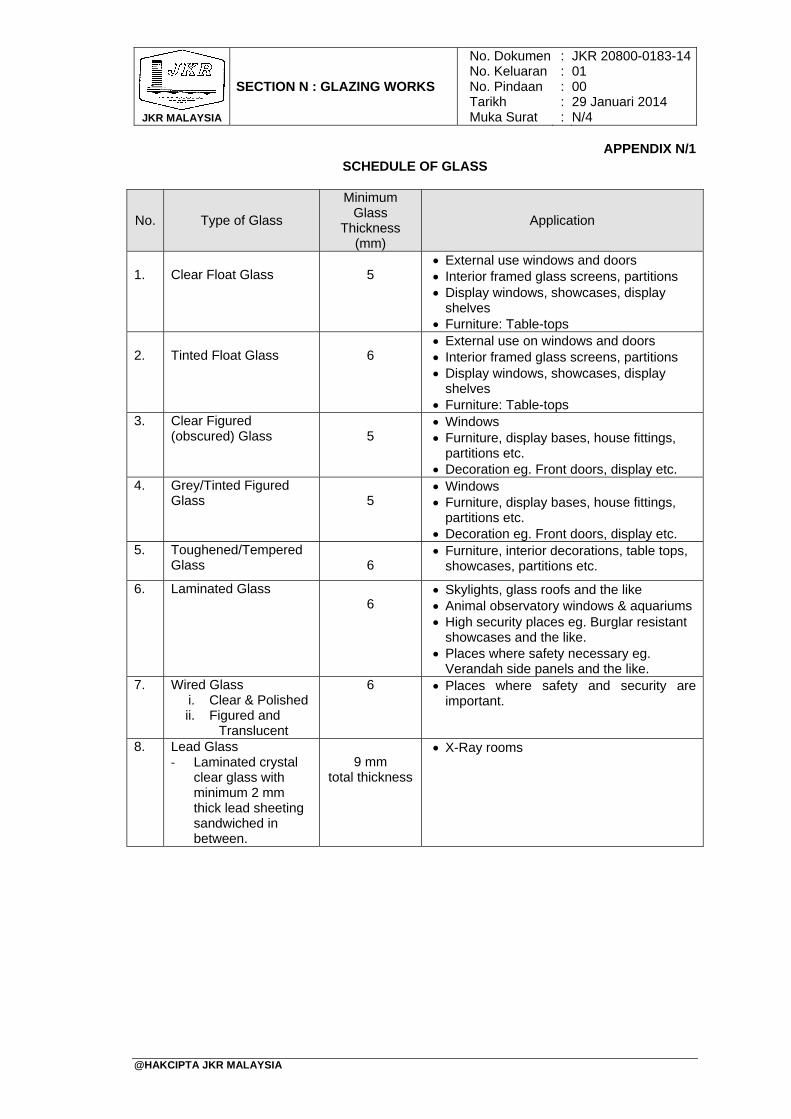
JKR MALAYSIA
SECTION N : GLAZING WORKS
No. DokumenNo. KeluaranNo. PindaanTarikhMuka Surat
: : : : :
JKR 20800-0183-1401 00 29 Januari 2014 N/4
@HAKCIPTA JKR MALAYSIA
APPENDIX N/1 SCHEDULE OF GLASS
No. Type of Glass
Minimum Glass
Thickness (mm)
Application
1.
Clear Float Glass
5
External use windows and doors Interior framed glass screens, partitions Display windows, showcases, display
shelves Furniture: Table-tops
2.
Tinted Float Glass
6
External use on windows and doors Interior framed glass screens, partitions Display windows, showcases, display
shelves Furniture: Table-tops
3. Clear Figured (obscured) Glass
5
Windows Furniture, display bases, house fittings,
partitions etc. Decoration eg. Front doors, display etc.
4. Grey/Tinted Figured Glass
5
Windows Furniture, display bases, house fittings,
partitions etc. Decoration eg. Front doors, display etc.
5. Toughened/Tempered Glass
6
Furniture, interior decorations, table tops, showcases, partitions etc.
6. Laminated Glass 6
Skylights, glass roofs and the like Animal observatory windows & aquariums High security places eg. Burglar resistant
showcases and the like. Places where safety necessary eg.
Verandah side panels and the like. 7. Wired Glass
i. Clear & Polished ii. Figured and
Translucent
6 Places where safety and security are important.
8. Lead Glass ‐ Laminated crystal
clear glass with minimum 2 mm thick lead sheeting sandwiched in between.
9 mm
total thickness
X-Ray rooms
TABLE OF CONTENTS
SECTION O: PAINTING WORKS PAGE
@HAKCIPTA JKR MALAYSIA
1. General 2. Painting To Timberwork 3. Painting To Metalwork 4. Painting To Masonry Work 5. Treatment To Fair Face Surfaces 6. Epoxy Coatings 7. Silicone Paint 8. Painting On Floor Surfaces 9. Painting To Timber-based Products 10. Painting To Gypsum Board and The Like 11. Painting To Laboratory Bench Tops 12. Varnishing 13. Painting Works For Buildings In Coastal Areas. 14. Painting Works To Clinical Areas (Hygienic Areas) 15. Completion Of Painting Works APPENDIX O/1: Paint Performance Warranty (Specimen)
O/1 O/2 O/2 O/3 O/4 O/4 O/4 O/4 O/5 O/5 O/6 O/6 O/6 O/7 O/7
O/8

JKR MALAYSIA
SECTION O : PAINTING WORKS
No. DokumenNo. KeluaranNo. PindaanTarikhMuka Surat
: : : : :
JKR 20800-0183-1401 00 29 Januari 2014 O/1
@HAKCIPTA JKR MALAYSIA
1. General
1.1 All paints to be used shall be those supplied by approved manufacturers. The quality of paints shall comply with MS 125 in respect of oil/enamel paints and MS 134 in respect of emulsion paints/acrylic paint.
1.2 Prior to commencing painting work, the Contractor shall submit the following to the
S.O.:
(i) Name of the paint manufacturer and the manufacturer’s certification that the paint conform to the relevant standard as specified in sub-section 1.1 hereof together with the proof that such certification have been verified by tests carried out by SIRIM or ISO in the last three (3) years.
(ii) The performance warranty by the manufacturer to the Government on the performance of the paint against any peeling, cracking, fungus/ algae growth and discoloration which may arise during a period of five (5) years or more from the date of practical completion due to insufficiency in material or workmanship. The terms of the performance warranty shall be as stipulated in APPENDIX O/1 and as approved by the S.O.
(iii) Name of the painting applicator as approved by the paint manufacturer including written evidence of the current approval.
(iv) A copy of the method statement including procedure for the painting works in accordance with these specification and manufacturer’s instructions.
1.3 All paints shall be delivered to the Site in the manufacturer's original sealed containers unopened and shall be used strictly in accordance with the manufacturer's instructions.
1.4 Paints shall not be adulterated and any paint that has deteriorated shall not be used
and shall be removed from the Site forthwith.
1.5 Unless otherwise specified in the Drawings, the types of paints to be sued for the work on exposed surfaces shall be as stated in the `Schedule of Paint Finish’ attached hereinafter.
1.6 The colours and tints of paints shall be selected by the S.O. and the priming,
undercoats and finishing coats shall be of approved differing tints and shall be obtained from the same manufacturer.
1.7 No painting shall be done under conditions which may jeopardize the quality of
finish paintwork. 1.8 During painting, care shall be taken to prevent stain or damage to other works.
1.9 Surfaces to be painted shall be dry, free from dirt, oil, grease, old loose paint and
other deleterious matter. All cracks shall be raked out and stopped and all holes and dents shall be filled.
1.10 Unless otherwise specified in the manufacturer’s instructions, each coat of paint
applied on timber or metal surfaces shall be allowed to dry and subsequently rubbed down lightly with sandpaper before the next coat is applied. Any dirt or dust shall be removed from preceding coats immediately before proceeding with application of the next coat.
1.11 All priming to shop fabricated components shall be done at shop.
1.12 All prime surfaces shall be inspected and approved by the S.O. before
commencement of painting works.

JKR MALAYSIA
SECTION O : PAINTING WORKS
No. DokumenNo. KeluaranNo. PindaanTarikhMuka Surat
: : : : :
JKR 20800-0183-1401 00 29 Januari 2014 O/2
@HAKCIPTA JKR MALAYSIA
1.13 Finish surfaces shall be uniform in finish and colour and be free from brush marks or other defects.
1.14 Sample areas showing all tints of paints to be used shall be prepared by the
Contractor as and when required by the S.O.
2. Painting To Timberwork
2.1 Painting To New Timberwork
2.1.1 Unless otherwise as shown on the Drawings, all exposed wrot surfaces of timber shall be painted as specified hereinafter.
2.1.2 Before painting to new timberwork, all knots shall be covered with knotting
and all nail holes, cracks, et cetera shall be stopped with white lead and putty (1:3) and shall be primed with aluminium wood primer well brushed in.
2.1.3 Unless otherwise specified, the prepared surface shall be painted with one
undercoat (alkyd undercoat) and shall be finished with two coats of premium semi-gloss fungus resisting alkyd paint or three (3) coats UV protection, low odour alkyd wood finish.
2.1.4 Timber decks shall be applied with three coats of scratch resistant, UV
protection, fast drying low odour urethane alkyd wood finish. Each preceding coat shall be allowed to dry thoroughly and rubbed down lightly with fine sand paper and thoroughly cleaned before applying the next coat.
2.1.5 All timber surfaces abutting concrete or brickwork shall be primed before
fixing or assembling. 2.1.6 All ironmongeries except hinges shall be removed before painting begins
and shall be carefully re-fixed.
2.2 Repainting Existing Timberwork
Where repainting to existing timber work is specified, the following procedure shall be adhered to. If the surface is intact, it shall be rubbed down with fine sand paper to the approval of the S.O. Then one coat of undercoat shall be applied followed by two (2) coats of gloss enamel paint unless otherwise specified. Where cracking and flaking have occurred, the entire existing paint shall be removed by burning off or by use of paint remover as approved by the S.O. The surfaces shall then be thoroughly cleaned and shall be applied with one coat minimum wood primer followed by one (1) undercoat and unless otherwise specified in the Drawings, shall be finished with two (2) coats of gloss enamel paint.
3. Painting To Metalwork
3.1 Painting New Steel And Ironwork
The areas to be painted shall be cleaned down and be free from rust, scale, oil, grease, dirt and dust. One (1) coat of approved metallic primer shall be applied followed by one (1) coat of premium alkyd undercoat unless specified, and shall be finished with two (2) finishing coats of gloss/semi-gloss fungus resisting alkyd paint. Soil and vent pipes shall be primed as above and given two (2) coats of approved bituminous paint.
JKR MALAYSIA
SECTION O : PAINTING WORKS
No. DokumenNo. KeluaranNo. PindaanTarikhMuka Surat
: : : : :
JKR 20800-0183-1401 00 29 Januari 2014 O/3
@HAKCIPTA JKR MALAYSIA
3.2 Repainting Existing Steel And Ironwork
3.2.1 Where repainting to existing steel or ironwork is stated in the Drawings, the following procedure shall be adhered to. Where a firm surface exists, it shall be scuffed with fine sand paper to the approval of the S.O. and spot primed if necessary before the application of by one (1) coat of premium alkyd undercoat unless specified, and shall be finished with two (2) finishing coats of gloss/semi-gloss fungus resisting alkyd or gloss enamel paint.
3.2.2 If the old paint is in a bad, deteriorated condition the whole paint shall be
removed by the use of approved paint remover or by scraping as approved by the S.O. The surface shall be thoroughly cleaned and shall be applied with one coat approved metallic primer, by one (1) coat of premium alkyd undercoat unless specified, and shall be finished with two (2) finishing coats of gloss/semi-gloss fungus resisting alkyd or gloss enamel paint.
3.3 Painting New Galvanized Ironwork
Where painting to new galvanized ironwork is specified, the surfaces shall be applied with one coat of approved self-etching quick drying metallic primer unless otherwise specified, and shall be finished with two finishing coats of gloss/semi-gloss fungus resisting alkyd paint or gloss enamel paint.
3.4 Repainting Existing Galvanized Ironwork
3.4.1 Where repainting to existing galvanized ironwork is specified, the following
procedure shall be adhered to. If the surface is not corroded, it shall be slightly sanded and all dirts, oil, and grease removed by washing with an approved solvent and applied with one (1) coat of approved metallic primer unless otherwise specified, shall be finished with two (2) finishing coats of gloss/semi-gloss fungus resisting alkyd paint or gloss enamel paint. If the surface has corroded, the whole paint shall be removed by the use of approved paint remover or by scraping as approved by S.O.
3.4.2 When the surface is completely clean, it shall be applied with one coat
approved metallic primer, unless otherwise specified, shall be finished with two finishing coats of gloss/semi-gloss fungus resisting alkyd paint or gloss enamel paint.
4. Painting To Masonry Work
4.1 Painting New Plastered/Masonry Surfaces
4.1.1 The new plastered or masonry surfaces shall be allowed to dry completely and shall be cleaned down to remove dust, dirt, plaster splashes, and the like. In case of old unpainted walls, all fungus, mosses, lichens and vegetative growth shall also be removed.
4.1.2 The cleaned surfaces of the external walls shall be applied with one coat of
approved alkaline resisting primer and unless otherwise specified in the Drawings, followed with two (2) coats of ultra-violet (UV) weather resistant emulsion paint.
4.1.3 The external wall surfaces shall be applied with one (1) coat of approved
alkaline resisting primer, unless otherwise stated in the Drawings, followed with two (2) coats of 100% acrylic with heat reflective and UV protected, and temperature reduction weather resistant emulsion paint for Green Ratings Certification as approved by the S.O.
JKR MALAYSIA
SECTION O : PAINTING WORKS
No. DokumenNo. KeluaranNo. PindaanTarikhMuka Surat
: : : : :
JKR 20800-0183-1401 00 29 Januari 2014 O/4
@HAKCIPTA JKR MALAYSIA
4.1.4 The internal wall surfaces shall be applied with one (1) coat of approved modified acrylic sealer, and unless otherwise as shown on the Drawings, followed with two (2) coats of low VOC acrylic paint.
4.2 Repainting Existing Plastered Or Masonry Surfaces
4.2.1 Where repainting to existing plastered or the masonry surface is specified,
the following procedure shall be adhered to. All existing paint shall be removed by scraping and the surface shall be washed. All cracks and other imperfections shall be made good and the surface should be allowed to dry completely.
4.2.2 The surface shall then be applied with two (2) coats of any other type of
water based emulsion paint as described hereinbefore for Painting New Plastered/Masonry Surfaces and as approved by the S.O.
4.3 Textured Wall
4.3.1 Natural Spray Granite textured wall shall be applied with one (1) coat of
approved alkaline resisting acrylic primer, unless otherwise stated in the Drawings, followed with two (2) layers natural fine stone and ceramic chips texture with high build acrylic resin and two (2) clear finish coats.
4.3.2 Spray Tile textured wall shall be applied with one (1) coat of approved
alkaline resisting acrylic primer, unless otherwise specified in the Drawings, followed with one (1) coat of spray tiles texture and two (2) coats of pure acrylic water based premium weather paint.
5. Treatment To Fair Face Surfaces Surfaces that are to be left bare such as fair-face brickwork, fair-face concrete or stones and the like shall be thoroughly clean, dry and free from grease, dust and loose or flaking materials. The surfaces shall then be treated with an approved colourless silicon-based water repellent liquid applied in accordance with the manufacturer’s instructions. The solution shall be applied in two (2) coats over the entire area and crevices by brushing.
6. Epoxy Coatings
Epoxy coatings shall be applied with one (1) coat of approved transparent epoxy sealer, followed with two (2) coats epoxy topcoat.
7. Silicone Paint
Silicone paint for external walls and ceiling shall be applied with one (1) coat of Pigmented Water Base Penetration Water Repellent and two (2) finishing coats of Breathable Silicone Paint of approved colour applied strictly in accordance with manufacturer’s instruction.
8. Painting On Floor Surfaces
8.1 Painting on concrete drive way shall be applied with one (1) coat of floor primer at 100 µm DFT, followed by one (1) coat of floor glass flake at 300 µm DFT or floor non-slip aggregate (fine/medium) and followed with two (2) coats of floor polyurethane (PU) topcoat at 50 µm DFT per coat.
JKR MALAYSIA
SECTION O : PAINTING WORKS
No. DokumenNo. KeluaranNo. PindaanTarikhMuka Surat
: : : : :
JKR 20800-0183-1401 00 29 Januari 2014 O/5
@HAKCIPTA JKR MALAYSIA
8.2 Painting on car park parking bay floors shall be applied with one (1) coat of floor primer at 100 µm DFT, than followed with two (2) coats of floor polyurethane (PU) topcoat at 50 µm DFT per coat.
8.3 Painting on TNB sub-station internal floors shall be applied with one (1) coat of
approved two-pack epoxy sealer, followed with two (2) coats of two pack epoxy floor coating at 50 µm DFT per coat, unless otherwise stated in the drawings
9. Painting To Timber-based Products 9.1 Chipboard Surfaces
9.1.1 Before painting, all nail holes, crevices and the like shall be stopped with
white lead and putty (1:3). The surface shall then be smoothened by rubbing down with fine sand paper and finally cleaned to remove dust. Where the board is to be finished with enamel paint, one (1) undercoat and two (2) finishing coats of gloss enamel paint shall be applied. If the board is to be finished with emulsion paint, one (1) undercoat and two (2) coats of emulsion paint shall be applied.
9.1.2 Where repainting to existing enamel paint finished chipboard is required, the
following procedure shall be adhered to. If the paintwork is still intact, it shall be rubbed down with fine sand paper to the approval of the S.O. Then one (1) coat of undercoat shall be applied followed by one (1) coat of gloss enamel paint.
9.1.3 Where cracking and flaking has occurred, the entire existing paint shall be
removed by burning off, as approved by the S.O. The surfaces shall then thoroughly cleaned and shall be applied with one (1) undercoat and finished with two (2) coats of gloss enamel paint.
9.1.4 Where repainting to existing emulsion paint finished chipboard is required,
the surface shall then be thoroughly cleaned and applied with two (2) coats of emulsion paint.
9.2 Hardboard Surfaces
Before painting to hardboard, all nail holes, crevices and the like shall be filled with approved putty. The surface shall then be applied with one (1) undercoat and two (2) coats of emulsion paint unless otherwise specified.
9.3 Wood Cement Board Surfaces
Before painting to wood cement board, all nail holes, crevices and the like shall be filled with approved filling compound of alkali resistant type. The surface shall then be lightly sanded and any dust should be removed from the surface with a piece of clean, coarse cloth. The surface shall then be applied with one (1) undercoat and two (2) coats of emulsion paint unless otherwise specified.
10. Painting To Gypsum Board And The Like
10.1 Before painting the surfaces shall be clean and free from dirt. The surfaces shall then be applied with one (1) undercoat and two (2) coats of emulsion paint. Similar procedure shall be followed where repainting to existing painted surfaces is required.
JKR MALAYSIA
SECTION O : PAINTING WORKS
No. DokumenNo. KeluaranNo. PindaanTarikhMuka Surat
: : : : :
JKR 20800-0183-1401 00 29 Januari 2014 O/6
@HAKCIPTA JKR MALAYSIA
11. Painting To Laboratory Bench Tops
11.1 Timber tops of benches in laboratories that are required to be painted shall be prepared as described hereinbefore for timber work. The surfaces shall then be applied with one (1) coat aluminium wood primer followed by one (1) coat approved chemical resistant primer and finished with two (2) coats of approved chemical resistant gloss enamel paint in accordance with manufacturer’s instructions.
11.2 Where repainting to existing timber tops laboratory benches is required, the
surfaces shall be rubbed down lightly with fine sand paper. The surfaces shall then be thoroughly cleaned and shall be applied with one (1) coat of approved chemical resistant primer followed by one (1) coat of approved chemical resistant gloss enamel paint.
12. Varnishing
12.1 Varnishing To New Timberwork
12.1.1 The surfaces to be varnished shall be smoothened with fine sand paper and all crevices, holes and the like, if any, shall be filled with approved whiting. It shall be clean, dry, free from dust, dirt and wax before the application of varnish. Unless otherwise approved by the S.O, the surfaces shall be applied with three (3) coats of approved UV protection, low odour alkyd wood finish or varnishing mixture used strictly in accordance with the manufacturer's instructions.
12.1.2 Where non patented products are allowed to be used, the varnishing
mixture shall consists of methylated spirit, shellac and approved stain forming the first coat followed by one (1) coat of an approved mixture consisting of thinner and lacquer. The mixtures shall be of uniform consistency throughout. Unless otherwise specified in the Drawings, the finish shall be gloss and as approved by the S.O.
12.1.3 Timber deck surfaces shall be applied with three (3) coats of approved
scratch resistant, UV protection, fast drying low odour urethane alkyd wood finish
12.2 Re-varnishing To Existing Timberwork
12.2.1 Where re-varnishing to timberwork is specified in the Drawings or described
in the B.Q., the surface shall first be thoroughly scuffed to remove the existing varnish. The surface shall then be smoothened with fine sand paper, cleaned, dried and free from dust, dirt and wax. It shall then be varnished as described hereinbefore for new timberwork.
13. Painting Works For Buildings In Coastal Areas.
13.1 External walls shall be applied with one (1) coat of approved pliolite based alkaline resisting primer sealer, unless otherwise specified in the Drawings, followed with two (2) coats of elastomeric weather resistant paint of approved colour applied strictly in accordance to manufacturer’s instruction.
13.2 Unless otherwise specified in the Drawings, the internal walls shall be applied with one (1) coat of approved water based alkaline resisting acrylic wall sealer, followed with two (2) coats of low volatile organic compounds (VOCs), alkylphenolethoxylate (APEO) free, formaldehyde free acrylic premium emulsion paint of approved colour applied strictly in accordance to manufacturer’s instruction.
JKR MALAYSIA
SECTION O : PAINTING WORKS
No. DokumenNo. KeluaranNo. PindaanTarikhMuka Surat
: : : : :
JKR 20800-0183-1401 00 29 Januari 2014 O/7
@HAKCIPTA JKR MALAYSIA
13.3 Mild steel shall be applied with one (1) coat of zinc rich epoxy, one (1) coat of surface tolerance epoxy mastic and followed with two (2) coats of polyurethane topcoat.
13.4 Galvanized steel shall be applied with one (1) coat of surface tolerance epoxy mastic and followed with two (2) coats of polyurethane topcoat.
13.5 Roofing sheet coatings for marine environment shall refer to SECTION G:
ROOFING WORKS.
13.6 Coatings of fasteners used shall comply with AS 3566 Class 4 and be certified as such by the supplier of fasteners and as approved by the S.O.
14. Painting Works To Clinical Areas (Hygienic Areas) 14.1 All external walls shall be applied with one (1) coat of approved siloxane primer
sealer, unless otherwise stated in the Drawings, followed with two (2) coats of silicone emulsion water repellent paint applied strictly in accordance to manufacturer’s instruction.
14.2 Internal walls shall be applied with one (1) coat of approved ultra-low VOCs alkaline
resisting primer sealer, followed with two (2) coats of anti-bacteria, anti-fungus, low VOCs, 100% APEO free, formaldehyde free acrylic premium emulsion paint.
15. Completion Of Painting Works 15.1 On completion of paintwork, all paint marks inadvertently left on glass, floors, tiles
and other surfaces shall be removed. Any stain or marking on finished paintwork shall be removed and touched up to the approval of the S.O.
JKR MALAYSIA
SECTION O : PAINTING WORKS
No. DokumenNo. KeluaranNo. PindaanTarikhMuka Surat
: : : : :
JKR 20800-0183-1401 00 29 Januari 2014 O/8
@HAKCIPTA JKR MALAYSIA
APPENDIX O/1 PAINT PERFORMANCE WARRANTY (SPECIMEN)
1. Coverage of Performance Warranty
We …..……………………………………………….. the paint Manufacturer hereby warrants that for a period of five (5) years from the date of Practical Completion, the paint system shall not be affected by the following defects: (i) Peeling This condition is manifested when the paint film peels away or detaches from the substrate. (ii) Cracking This condition is manifested by any visible cracking on the paint film other than that caused by
plastering cracks and structural defects. (iii) Fungus/Algae Growth This condition is established when there is a growth of micro-organisms on the surface of the
paint films which would result in the marring of the appearance of the paint film through discoloration.
(iv) Discoloration This condition occurs when the coating loses its original colour in patches and excessive
discoloration appears.
2. Procedure for Claims
(i) Any defect claims shall be made in writing and delivered by post or by hand to the Manufacturer.
(ii) A technical team from the Manufacturer will be dispatched to evaluate the nature of the claim. Should our findings conclude the defects as within the scope of warranty, then the Manufacturer shall make good such defects.
(iii) Should the Manufacturer’s technical team conclude that the defects falls outside the scope of the warranty, the Manufacturer shall not be held responsible for the claim.
(iv) Should the Government disagree with the conclusion of the technical team pertaining to the defects in particular, then an independent third party competent in such technical evaluation shall be appointed to investigate the disputed defects.
(v) The appointment of independent third party competent in such technical evaluation shall only be appointed upon the mutual agreement between the Government and the Manufacturer.
(vi) The findings of the third party shall be conclusive and mutually accepted by the Government and the Manufacturer.
(vii) If the findings of the independent third party are within the coverage of this performance warranty, all cost shall be borne by the Manufacturer or otherwise such cost shall be borne by the Contractor.
(viii) All claims for the defects must be received by the Manufacturer not later than fourteen (14) days from the expiry of the warranty period.
MANUFACTURER ………………………………….. Company Stamp …………………………………….. ……………………………………… ………………………………….. Signature Name: Date:
WITNESS ………………………………….. Company Stamp …………………………………….. ……………………………………… ………………………………….. Signature Name: Date:
TABLE OF CONTENTS
SECTION P: ROADS AND HARDSTANDING
PAGE
@HAKCIPTA JKR MALAYSIA
1. General 2. Flexible Pavement TABLE P1 : Gradation Limits For Drainage Layer TABLE P2 : Gradation Limits For Sub-base TABLE P3 : Gradation Limits For Crushed Aggregate Roadbase TABLE P4 : Gradation Limit For Wet-mix Roadbase 3. Horizontal Alignment, Surface Levels And Surface Regularity Of
Pavement Courses
TABLE P5 : Tolerances In Surface Levels Of Pavement Courses 4. Shoulders 5. Concrete Pavement 6. Road Furniture 7. Street Lighting
P/1 P/1 P/2 P/3 P/4 P/6 P/8 P/8 P/8 P/10 P/10 P/10

JKR MALAYSIA
SECTION P : ROADS AND HARDSTANDING
No. DokumenNo. KeluaranNo. PindaanTarikhMuka Surat
: : : : :
JKR 20800-0183-1401 00 29 Januari 2014 P/1
@HAKCIPTA JKR MALAYSIA
1. General
The construction of roads and hardstanding shall generally be carried out only after completion of all drainage systems, services and ducts which may affect the Works, unless otherwise agreed by the S.O.
2. Flexible Pavement
2.1 Subgrade
2.1.1 Subgrade means that part of the embankment or existing ground in cutting which is immediately below the sub-base or lower sub-base of the road pavement and shoulders.
2.1.2 Material for the top 300 mm of subgrade shall have a minimum soaked
laboratory California Bearing Ratio (CBR) as shown on the Drawing when compacted to 95% of the maximum dry density determined in the BS 1377 Compaction Test (4.5 kg Rammer Method). In the event CBR value not mentioned on the Drawing, a minimum CBR value of 5% shall be adopted.
2.1.3 Throughout the top 300 mm of subgrade, the materials shall be compacted
to not less than 95% of the maximum dry density determined in the BS 1377 Compaction Test (4.5 kg Rammer Method).
2.1.4 In cut area, the top 300 mm of the subgrade shall be scarified and
recompacted to 95% of the maximum dry density determined in the BS 1377 Compaction Test (4.5 kg Rammer Method). If the S.O. is fully satisfied that the subgrade in its natural state possesses a density exceeding the requirements, then the surface of the subgrade shall be trimmed and rolled to obtain a smooth finish.
2.1.5 Where the material in cut area is found to be unsuitable for use in the top
300mm of subgrade or to a suitable level to be determined by the S.O., it shall be removed and replaced with suitable material which shall be compacted as indicated above. Alternatively, stabilizing agent may be used subjected to the S.O. approval.
2.1.6 The subgrade shall be finished in a neat and workmanlike manner, and the
widths of embankments and cuts shall be everywhere at least of those specified or shown in the Drawings on both sides of the centre line. The top surface of the subgrade shall have the required shape, superelevation, levels and grades and shall be finished everywhere to within + 10 mm and - 30 mm of the required level.
2.1.7 Where subgrade construction encounters rock surfaces:
(i) Rock surfaces extend over the whole width of the formation:
The rock surface shall be trimmed to a free draining profile, at or below formation levels. No high spot shall protrude above the formation level. Any voids or cavities more than 0.5 m below the formation level shall be filled up with approved lean concrete having seven (7) days cube strength greater than 7 N/mm2. The rock surface shall then be brought up to the formation levels with approved crushed rock or gravel, regulated and blinded.
JKR MALAYSIA
SECTION P : ROADS AND HARDSTANDING
No. DokumenNo. KeluaranNo. PindaanTarikhMuka Surat
: : : : :
JKR 20800-0183-1401 00 29 Januari 2014 P/2
@HAKCIPTA JKR MALAYSIA
(ii) Rock outcrop occurs over part of the formation only :
The rock outcrop shall be cut down to a level not less than 300 mm below the formation level. The surface shall then be brought up to level with suitable subgrade material.
2.2 Drainage Layer
2.2.1 This work shall consist of furnishing, placing, compacting and shaping
drainage layer on a prepared and accepted subgrade in accordance with this Specification and the lines, levels, grades, dimensions and cross-sections as shown on the Drawings and/or as directed by the S.O.
2.2.2 Coarse aggregate shall be screened crushed hard rock and fine aggregate
shall be screened quarry dust or sand. The aggregate shall be well graded and lie within the limits as shown in TABLE P1.
TABLE P1: GRADATION LIMITS FOR DRAINAGE LAYER
2.2.3 Notwithstanding any earlier approval of finished subgrade, the surface of
the subgrade shall be, on completion of compaction and immediately before placing drainage layer, well closed and free from movement under the compaction plant and from ridges, cracks, loose material, pot holes, ruts or other defects. Any damage to or deterioration of the subgrade shall be made good in accordance with sub-section 2.1.
2.2.4 The material shall be transported, laid and compacted at a moisture content within the range + 1% to - 2% of the optimum moisture content determined in compliance with BS 5835 and without drying out or segregation.
2.2.5 The drainage layer shall be placed and compacted to the required width and thickness as shown on the Drawings, in one single layer.
2.2.6 The material shall be spread and lightly compacted with tracked spreading plant or other approved equipment with consideration given to the protection of the subgrade.
2.3 Sub-base
2.3.1 This work shall consist of furnishing, placing, compacting and shaping
sub-base material on a prepared and accepted subgrade in accordance with this Specification and the lines, levels, grades, dimensions and cross-sections as shown on the Drawings and/or as directed by the S.O.
2.3.2 Sub-base shall be a natural or artificial mixture of locally available
materials such as sand, gravel, crushed aggregate, et cetera, free from organic matter, clay lumps and other deleterious materials. It shall be well graded and conform to TABLE P2 and the following quality requirements:
B.S. Sieve Size (mm) Percentage Passing by Weight 75.0 37.5 20.0 10.0 5.0 2.00 1.18
100 75 - 100 60 - 90 25 - 75 10 - 45 0 - 20 0 - 10
JKR MALAYSIA
SECTION P : ROADS AND HARDSTANDING
No. DokumenNo. KeluaranNo. PindaanTarikhMuka Surat
: : : : :
JKR 20800-0183-1401 00 29 Januari 2014 P/3
@HAKCIPTA JKR MALAYSIA
(i) The CBR of the sub-base shall not be less than 30% or as shown on the Drawings when compacted to 95% of the maximum dry density determined in the B.S. 1377 Compaction Test (4.5 kg rammer method) and soaked for 4 days under a surcharge of 4.5 kg. This shall involve carrying out a series of CBR tests at various dry densities, using the field moisture content. The field density must then be measured at a number of points using the sand replacement method and the CBR deduced from the mean of the field density measurements.
(ii) If more than 10% of the material is retained on the BS 20.0 mm sieve, the whole material can be assumed without test to have a CBR value of 30% or more.
(iii) The plasticity index when tested in accordance with BS 1377 shall be not more than 12.
(iv) The 10% fines value when tested in accordance with MS 30 shall be not less than 30 kN.
(v) The sand equivalent of aggregate fraction passing the No. 4 (4.75 mm) sieve when tested in accordance with ASTM D 2419 shall be not less than 45%.
TABLE P2 : GRADATION LIMITS FOR SUB-BASE
2.3.3 Prior to placing any sub-base material, the underlying subgrade
(particularly the top 300 mm of the subgrade) shall have been shaped and compacted in accordance with the provisions of sub-section 2.1 or sub-section 2.2 as appropriate. Notwithstanding any earlier approval of finished subgrade, the surface of the subgrade shall be, on completion of compaction and immediately before placing sub-base layer, well closed and free from movement under the compaction plant and from ridges, cracks, loose material, potholes, ruts or other defects. Any damage to or deterioration of the subgrade shall be made good in accordance with sub-section 2.1.
2.3.4 Sub-base material shall be transported, laid and compacted at a moisture content within the range + 1% to - 2% of the optimum moisture content without drying out or segregation.
2.3.5 Sub-base material shall be placed over the full width of the formation to the
required thickness as shown on the Drawings or directed by the S.O. in one layer or more, each layer not exceeding 200 mm compacted thickness. Where two or more layers are required, they shall be of approximately equal thickness and none shall be less than 100 mm compacted thickness.
2.3.6 Each layer of sub-base shall be processed as necessary to bring its moisture content to a uniform level throughout the material suitable for compaction, and shall then be compacted using suitable compaction equipment approved by the S.O. to not less than 95% of the maximum dry density determined in the BS 1377 Compaction Test (4.5 kg rammer
BS Sieve Size (mm) Percentage Passing by Weight 75.0 37.5 20.0 10.0 5.0
0.600 0.075
100 85 - 100 65 - 100 45 - 100 25 - 85 8 - 45 0 - 10
The particle size shall be determined by the washing and sieving method of BS 1377.
JKR MALAYSIA
SECTION P : ROADS AND HARDSTANDING
No. DokumenNo. KeluaranNo. PindaanTarikhMuka Surat
: : : : :
JKR 20800-0183-1401 00 29 Januari 2014 P/4
@HAKCIPTA JKR MALAYSIA
method). Compaction shall be carried out in a longitudinal direction along the roadbed, and shall generally begin at the outer edge and progress uniformly towards the crown on each side in such a manner that each section receives equal compactive effort, all to the satisfaction of the S.O.
2.3.7 All loose, segregated or other defective areas shall be removed to the full
thickness of the layer, and new sub-base material laid and compacted.
2.3.8 The sub-base shall be finished in a neat and workmanlike manner, and shall have an average thickness over any 100 m length not less than the required thickness. The top surface of the sub-base shall have the required shape, superelevation, levels and grades, and shall be everywhere within the tolerances as specified in sub-section 3.2.
2.4 Crushed Aggregate Roadbase
2.4.1 This work shall consist of furnishing, placing, compacting and shaping
crushed aggregate roadbase material on a prepared and accepted subgrade or sub-base in accordance with this Specification and the lines, levels, grades, dimensions and cross-sections as shown on the Drawings and/or as directed by the S.O.
2.4.2 Crushed aggregate roadbase material shall be crushed rock, crushed gravel or a mixture of crushed rock and gravel, which shall be hard, durable, clean and essentially free from clay and other deleterious materials. The material shall conform to the following physical and mechanical quality requirements:
(i) The plasticity index when tested in accordance with BS 1377 shall be
not more than 6. (ii) The aggregate crushing value when tested in accordance with MS 30
shall be not more than 25%. (iii) The flakiness index when tested in accordance with MS 30 shall be
not more than 25%. (iv) The weighted average loss of weight in the magnesium sulfate
soundness test (5 cycles) when tested in accordance with AASHTO Test Method T 104 shall be not more than 18%.
(v) The material shall have a CBR value of not less than 80% when compacted to 95% of the maximum dry density determined in the B.S. 1377 Compaction Test (4.5 kg rammer method) and soaked for 4 days under a surcharge of 4.5 kg
(vi) The sand equivalent of aggregate fraction passing the No. 4 (4.75 mm) sieve when tested in accordance with ASTM D 2419 shall be not less than 45%.
(vii) The gradation shall comply with the envelope as shown in TABLE P3.
TABLE P3 : GRADATION LIMITS FOR CRUSHED AGGREGATE ROADBASE
B.S. Sieve Size (mm) Percentage Passing by Weight 50.0 37.5 28.0 20.0 10.0 5.0 2.00
0.425 0.075
100 85 - 100 70 - 100 60 - 90 40 - 65 30 - 55 20 - 40 10 - 25 2 - 10
The particle size shall be determined by the washing and sieving method of BS 1377.
JKR MALAYSIA
SECTION P : ROADS AND HARDSTANDING
No. DokumenNo. KeluaranNo. PindaanTarikhMuka Surat
: : : : :
JKR 20800-0183-1401 00 29 Januari 2014 P/5
@HAKCIPTA JKR MALAYSIA
2.4.3 Prior to placing any crushed aggregate roadbase material, the subbase shall have been constructed in accordance with the provisions of sub-section 2.3.
2.4.4 Crushed aggregate roadbase shall be placed to the required width and thickness as shown on the Drawings or directed by the S.O. in one layer or more, each layer not exceeding 200 mm compacted thickness.
2.4.5 Where two or more layers are required, each layer shall be of
approximately equal thickness and none shall be less than 100 mm compacted thickness.
2.4.6 The material shall be spread using a motor grader of sufficient capacity or other approved mechanical spreader, at the optimum moisture content + 1%.
2.4.7 Compaction shall be carried out using suitable approved equipment, in a longitudinal direction, and begin at the lower edges and progress towards the crown, or in the case of superelevation towards the upper edge, in such a manner that each section receives equal compactive effort, sufficient to produce a density of not less than 95% of the dry maximum density as determined by BS 1377: Test 13.
2.4.8 Throughout the placing, adjustment of moisture content and compaction of crushed aggregate roadbase material, care shall be taken to maintain a uniform gradation of the material and prevent its separation into coarse and fine parts, all to the satisfaction of the S.O.
2.4.9 The crushed aggregate roadbase width shall be everywhere at least that specified or shown on the Drawings on both sides of the centre-line; and its average thickness over any 100 m length shall be not less than the required thickness.
2.4.10 The surface of the roadbase shall on completion of compaction and immediately before placing bituminous surfacing be well closed and free from movement under the compaction plant and from ridges, cracks, loose material, pot holes, ruts other defects.
2.4.11 All loose, segregated or otherwise defective areas shall be removed to the
full thickness of the layer, and new material laid and compacted. The addition of fine material will not be permitted.
2.4.12 The surface shall be to the required level and grade and comply with the tolerances as specified in sub-section 3.2.
2.5 Wet-Mix Roadbase
2.5.1 This works shall consist of furnishing, placing, compacting wet-mix
roadbase on a prepared and accepted sub-base in accordance with this Specification and the lines and levels as shown on the Drawings and/or as directed by the S.O.
2.5.2 Aggregate for wet-mix roadbase shall be crushed rock, crushed gravel or a
mixture of crushed rock and gravel, which shall be hard, durable, clean and essentially free from clay and other deleterious materials.
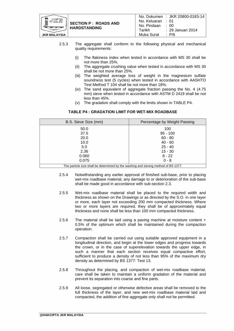
JKR MALAYSIA
SECTION P : ROADS AND HARDSTANDING
No. DokumenNo. KeluaranNo. PindaanTarikhMuka Surat
: : : : :
JKR 20800-0183-1401 00 29 Januari 2014 P/6
@HAKCIPTA JKR MALAYSIA
2.5.3 The aggregate shall conform to the following physical and mechanical quality requirements:
(i) The flakiness index when tested in accordance with MS 30 shall be
not more than 25%. (ii) The aggregate crushing value when tested in accordance with MS 30
shall be not more than 25%. (iii) The weighted average loss of weight in the magnesium sulfate
soundness test (5 cycles) when tested in accordance with AASHTO Test Method T 104 shall be not more than 18%.
(iv) The sand equivalent of aggregate fraction passing the No. 4 (4.75 mm) sieve when tested in accordance with ASTM D 2419 shall be not less than 45%.
(v) The gradation shall comply with the limits shown in TABLE P4.
TABLE P4 : GRADATION LIMIT FOR WET-MIX ROADBASE
B.S. Sieve Size (mm) Percentage by Weight Passing
50.0 37.5 20.0 10.0 5.0 2.36
0.060 0.075
100 95 - 100 60 - 80 40 - 60 25 - 40 15 - 30 8 - 22 0 - 8
The particle size shall be determined by the washing and sieving method of BS 1377.
2.5.4 Notwithstanding any earlier approval of finished sub-base, prior to placing
wet-mix roadbase material, any damage to or deterioration of the sub-base shall be made good in accordance with sub-section 2.3.
2.5.5 Wet-mix roadbase material shall be placed to the required width and
thickness as shown on the Drawings or as directed by the S.O. in one layer or more, each layer not exceeding 200 mm compacted thickness. Where two or more layers are required, they shall be of approximately equal thickness and none shall be less than 100 mm compacted thickness.
2.5.6 The material shall be laid using a paving machine at moisture content +
0.5% of the optimum which shall be maintained during the compaction operation.
2.5.7 Compaction shall be carried out using suitable approved equipment in a longitudinal direction, and begin at the lower edges and progress towards the crown, or in the case of superelevation towards the upper edge, in such a manner that each section receives equal compactive effort, sufficient to produce a density of not less than 95% of the maximum dry density as determined by BS 1377: Test 13.
2.5.8 Throughout the placing, and compaction of wet-mix roadbase material, care shall be taken to maintain a uniform gradation of the material and prevent its separation into coarse and fine parts.
2.5.9 All loose, segregated or otherwise defective areas shall be removed to the full thickness of the layer, and new wet-mix roadbase material laid and compacted, the addition of fine aggregate only shall not be permitted.
JKR MALAYSIA
SECTION P : ROADS AND HARDSTANDING
No. DokumenNo. KeluaranNo. PindaanTarikhMuka Surat
: : : : :
JKR 20800-0183-1401 00 29 Januari 2014 P/7
@HAKCIPTA JKR MALAYSIA
2.5.10 The wet-mix roadbase width shall be everywhere at least that specified or shown on the Drawings on both sides of the centre-line. The average thickness measured over any 100 m length shall be not less than shown on the Drawings or specified and the minimum thickness measured at any one point shall be not less than the thickness shown or specified.
2.5.11 The surface of the wet-mix roadbase shall, on completion of compaction and immediately before placing bituminous surfacing, be well closed and free from movement under the compaction plant and from ridges, cracks, loose material, pot holes, ruts or other defects.
2.5.12 The surface shall be to the required level and grade and comply with the tolerances specified in sub-section 3.2.
2.6 Bituminous Pavement Courses
2.6.1 Bituminous prime coat
2.6.1.1 This work shall consist of the careful and thorough cleaning of
the surface of a prepared and accepted unbound roadbase and cement-treated base (CTB), and the furnishing and application to the cleaned roadbase and CTB surface of a bituminous prime coat, all in accordance with this Specification and the lines, dimensions and cross-sections as shown on the Drawings and/or as directed by the S.O.
2.6.1.2 The materials, equipment and construction methods shall be in
accordance with JKR Specification No. JKR/SPJ/2008-S4, sub-section 4.3.1 or the latest edition published by JKR.
2.6.2 Bituminous tack coat
2.6.2.1 This work shall consist of the careful and thorough cleaning of
the surface of a prepared and accepted bituminous or bitumen primed pavement course, and the furnishing and application to the cleaned surface of a bituminous tack coat prior to the construction of an overlying bituminous pavement course, all in accordance with this Specification and the lines, dimensions and cross-sections as shown on the Drawings and/or as required by the S.O.
2.6.2.2 The materials, equipment and construction methods shall be in accordance with JKR Specification No. JKR/SPJ/2008-S4, sub-section 4.3.2 or the latest edition published by JKR.
2.6.3 Asphaltic concrete
2.6.3.1 This work shall consist of furnishing, placing, shaping and
compacting asphaltic concrete binder course and/or wearing course on a prepared and accepted bituminous or bitumen primed pavement course, and shall include the careful and thorough cleaning of surfaces which are to be covered prior to the application of bituminous prime coat and tack coat. The work shall be carried out all in accordance with this Specification and the lines, levels, grades, dimensions and cross-sections as shown on the Drawings and/or as required by the S.O.
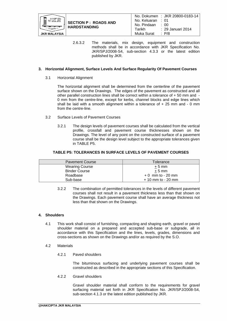
JKR MALAYSIA
SECTION P : ROADS AND HARDSTANDING
No. DokumenNo. KeluaranNo. PindaanTarikhMuka Surat
: : : : :
JKR 20800-0183-1401 00 29 Januari 2014 P/8
@HAKCIPTA JKR MALAYSIA
2.6.3.2 The materials, mix design, equipment and construction methods shall be in accordance with JKR Specification No. JKR/SPJ/2008-S4, sub-section 4.3.3 or the latest edition published by JKR.
3. Horizontal Alignment, Surface Levels And Surface Regularity Of Pavement Courses
3.1 Horizontal Alignment
The horizontal alignment shall be determined from the centerline of the pavement surface shown on the Drawings. The edges of the pavement as constructed and all other parallel construction lines shall be correct within a tolerance of + 50 mm and - 0 mm from the centre-line, except for kerbs, channel blocks and edge lines which shall be laid with a smooth alignment within a tolerance of + 25 mm and - 0 mm from the centre-line.
3.2 Surface Levels of Pavement Courses
3.2.1 The design levels of pavement courses shall be calculated from the vertical
profile, crossfall and pavement course thicknesses shown on the Drawings. The level of any point on the constructed surface of a pavement course shall be the design level subject to the appropriate tolerances given in TABLE P5.
TABLE P5: TOLERANCES IN SURFACE LEVELS OF PAVEMENT COURSES
3.2.2 The combination of permitted tolerances in the levels of different pavement
courses shall not result in a pavement thickness less than that shown on the Drawings. Each pavement course shall have an average thickness not less than that shown on the Drawings.
4. Shoulders
4.1 This work shall consist of furnishing, compacting and shaping earth, gravel or paved
shoulder material on a prepared and accepted sub-base or subgrade, all in accordance with this Specification and the lines, levels, grades, dimensions and cross-sections as shown on the Drawings and/or as required by the S.O.
4.2 Materials
4.2.1 Paved shoulders
The bituminous surfacing and underlying pavement courses shall be constructed as described in the appropriate sections of this Specification.
4.2.2 Gravel shoulders
Gravel shoulder material shall conform to the requirements for gravel surfacing material set forth in JKR Specification No. JKR/SPJ/2008-S4, sub-section 4.1.3 or the latest edition published by JKR.
Pavement Course Tolerance Wearing Course Binder Course Roadbase Sub-base
+ 5 mm + 5 mm
+ 0 mm to - 20 mm + 10 mm to - 20 mm
JKR MALAYSIA
SECTION P : ROADS AND HARDSTANDING
No. DokumenNo. KeluaranNo. PindaanTarikhMuka Surat
: : : : :
JKR 20800-0183-1401 00 29 Januari 2014 P/9
@HAKCIPTA JKR MALAYSIA
4.2.3 Earth shoulders
Earth shoulder material shall be suitable material as described in JKR Specification No. JKR/SPJ/2013-S2, sub-section 2.2 or the latest edition published by JKR.
4.2.4 Construction
4.2.4.1 Shoulders shall be constructed in stages or in one operation as directed or approved by the S.O., but in no instance shall a shoulder be built up to a level higher than that part of the abutting carriageway structure which has been completed and accepted.
4.2.4.2 Prior to placing any shoulder material, the underlying sub-base
or subgrade shall have been shaped and compacted in accordance with the provisions of JKR Specification No. JKR/SPJ/2008-S4, sub-sections 4.1.2.3 and 2.2.7 or the latest edition published by JKR respectively, and the abutting carriageway structure course or courses shall likewise have been shaped and compacted in accordance with the provisions of the appropriate sub-sections of this Specification. Notwithstanding any earlier approval of the underlying and abutting pavement courses, any damage to or deterioration of these underlying and abutting pavement courses shall be made good to the satisfaction of the S.O. before shoulder construction proceeds.
4.2.4.3 Shoulders shall be placed to the required width and thickness as shown on the Drawings or as directed by the S.O. in one layer or more, each layer not exceeding 200 mm compacted thickness at the point of maximum thickness. Where two or more layers are required, they shall be of approximately equal shape and thickness, and none shall be less than 100 mm compacted thickness at the point of maximum thickness.
4.2.4.4 Each layer of shoulder material shall be processed as
necessary to bring its moisture content to a uniform level throughout the material suitable for compaction, and shall then be compacted using suitable compaction equipment approved by the S.O. to not less than 95% of the maximum dry density determined in the BS 1377 Compaction Test (4.5 kg rammer method). Compaction shall be carried out in a longitudinal direction along the shoulder and shall generally begin at the outer edge and progress uniformly towards the carriageway, except on super-elevated curves where rolling shall begin at lower edge and progress uniformly towards the higher edge. In all cases, compaction shall be carried out in such a manner that each section receives compactive effort appropriate to its thickness, all to the satisfaction of the S.O.
4.2.4.5 Throughout the placing, adjustment of moisture content and compaction of shoulder material, care shall be taken to maintain a uniform gradation of the material and prevent its separation into coarse and separate parts, all to the satisfaction of the S.O.
4.2.4.6 Where shown on the Drawings or directed by the S.O., earth
shoulders shall be turfed in accordance with JKR Specification
JKR MALAYSIA
SECTION P : ROADS AND HARDSTANDING
No. DokumenNo. KeluaranNo. PindaanTarikhMuka Surat
: : : : :
JKR 20800-0183-1401 00 29 Januari 2014 P/10
@HAKCIPTA JKR MALAYSIA
No. JKR/SPJ/2013-S2, sub-section 2.2.8 or the latest edition published by JKR.
4.2.4.7 Shoulders shall be finished in a neat and workmanlike manner. The total width of carriageway and shoulder shall be everywhere at least that specified or shown on the Drawings on both sides of the centre-line. The top surface of each shoulder shall have the required shape, super-elevation, levels and grades, shall be everywhere within 10 mm of the required plane, and shall provide a flush joint with the carriageway surface and shall be uniformly free draining away from the carriageway, all to the satisfaction of the S.O.
5. Concrete Pavement
Concrete Pavement works shall be in accordance with JKR Specification No. JKR/SPJ/1988, section 5: Portland Cement Concrete Pavement or the latest edition published by JKR.
6. Road Furniture
6.1 Corrugated Sheet Steel Beam Guardrail
The supply and method of installation of guardrails shall be in accordance with JKR Specification No. JKR/SPJ/1988, section 6, sub-section 6.1 or the latest edition published by JKR.
6.2 Traffic Signs
The supply and method of installation of traffic signs shall be in accordance with JKR Specification No. JKR/SPJ/1988, section 6, sub-section 6.2 or the latest edition published by JKR.
6.3 Road Markings
The supply and application of road markings shall be in accordance with JKR Specification No. JKR/SPJ/2012-S6, section 6, sub-section 6.3 or the latest edition published by JKR.
6.4 Concrete Kerb
The supply and installation of concrete kerb shall be in accordance with JKR Specification No. JKR/SPJ/1988, section 6, sub-section 6.4 or the latest edition published by JKR.
7. Street Lighting
The supply and installation of street lighting shall be in accordance with JKR Specification No. JKR/SPJ/2011-S7: Road Lighting or the latest edition published by JKR.
TABLE OF CONTENTS
SECTION Q: FENCING AND GATES
PAGE
@HAKCIPTA JKR MALAYSIA
1. General 2. Mild Steel Post And Bracings 3. Chain Link Mesh, Straining 4. Fencing 5. Gates 6. Painting Of Fence And Gates
Q/1 Q/1 Q/1 Q/1 Q/2 Q/2

JKR MALAYSIA
SECTION Q : FENCING AND GATES
No. DokumenNo. KeluaranNo. PindaanTarikhMuka Surat
: : : : :
JKR 20800-0183-1401 00 29 Januari 2014 Q/1
@HAKCIPTA JKR MALAYSIA
1. General
1.1 Unless otherwise as shown on the Drawings, fencing shall be of chain link type as specified hereunder.
1.2 Unless otherwise as shown on the Drawings, the height of the fence shall be 1500 mm from the ground up to the full height of the chain link.
1.3 The fence shall be erected to the extent and location as shown on the site plan. Where fencing is to be located on the boundary of the Site, the Contractor shall ensure that its construction shall not infringe the adjoining properties.
2. Mild Steel Post And Bracings
2.1 Unless otherwise as shown on the Drawings, mild steel angle posts and bracings
shall be of size 57 mm x 57 mm x 6 mm. All steel members for fencing and gates shall be free from rust, scales and other defects and shall be to the approval of the S.O. Previously used steel members shall not be used in the construction of new fencing and gates. Before delivery to the Site, the steel members for fencing and gates shall be pre-cut and assembled at the Contractor's workshop and painted with one coat of approved metallic primer.
2.2 Where three strands of barbed wires are required, a mild steel angle arm 430 mm long, of the same cross sectional dimension as the post shall be welded at the top of the post at 450 inclination. Where six strands of barbed wires are required, two pieces of mild steel angle arms as specified hereinbefore shall be welded to the top of each post forming the shape Y with each arm having three strands of barbed wires. The welding used shall be of continuous fillet welds. Necessary holes shall be made in the posts, arms and bracings for insertions of fixing bolts and clips.
3. Chain Link Mesh, Straining
Chain link mesh, straining wires and barbed wires shall be made of galvanized steel and of approved quality. The mesh shall be of size 64 mm made up of 3.25 mm (10 gauges) diameter wire. Straining wires shall be of 4.06 mm (8 gauges) diameters and barbed wires shall be of 2.64 mm (12 gauges) diameters.
4. Fencing
4.1 Unless otherwise as shown on the Drawings, the mild steel angle posts shall be
erected at 3000 mm centres commencing from the gate post and the posts shall be embedded plumb in 1:3:6-25 mm concrete footings of size 250 mm x 250 mm x 600 mm deep. Mild steel angle bracings of the same cross sectional dimensions as the post shall be fixed at all corners, bends, junctions, gate posts and at every five bays of straight fencing.
4.2 The bracings shall be fixed at an inclination of 450 to the horizontal with top end bolted to the post, 300 mm below the top of the post and the bottom end encased in concrete footing as described hereinbefore.
4.3 The chain link mesh shall be stretched across the posts and secured in place using approved fencing clips. The end of chain link fencing abutting mild steel gate posts shall be fixed by means of 19 mm x 3 mm mild steel flat straps drawn through the mesh and bolted using 10 mm diameter mild steel bolts to 25 mm x 25 mm x 6 mm mild steel plates welded to the posts at equal intervals of 300 mm. Where gate posts are non-metal, the termination of the fencing at the gate shall be by means of
JKR MALAYSIA
SECTION Q : FENCING AND GATES
No. DokumenNo. KeluaranNo. PindaanTarikhMuka Surat
: : : : :
JKR 20800-0183-1401 00 29 Januari 2014 Q/2
@HAKCIPTA JKR MALAYSIA
another mild steel angle post fixed to one side of the gate post and strengthened by bracing as described hereinbefore. The chain link mesh shall then be strained by three strands of 4.06 mm (8 gauges) diameter galvanized steel straining wires threaded through the mesh and fixed to the posts.
4.4 Where shown on the Drawings, the bottom of the chain link mesh shall be buried in continuous 1:3:6-25 mm concrete curbs. Unless otherwise detailed in the Drawings, the cross-sectional dimension of curbs shall be 125 mm wide x 375 mm high with 150 mm protruding above the ground. The portion of the curb above the ground shall be rendered with 13 mm thick 1:6 cement render to a wood float finish.
5. Gates
The gates shall be constructed as shown on the Drawings.
6. Painting Of Fence And Gates
The metallic primer previously applied to the steelwork at the workshop shall be touched up where necessary. Unless otherwise specified, the posts, bracings and gates shall be finished with two (2) coats of approved aluminium paint.
TABLE OF CONTENTS
SECTION R: LANDSCAPING AND TURFING WORKS
PAGE
@HAKCIPTA JKR MALAYSIA
1. General 2. Classifications And Characteristics Of Plants 3. Size Of Plants 4. Handling And Planting 5. Soil Mixture, Soil Conditioners And Chemical Fertilizers 6. Turfing 7. Football And Playing Fields 8. Relocation And Protection Of Existing Tress 9. Maintenance Of Plant And Turf 10. Final Handing Over
R/1 R/1 R/1 R/3 R/4 R/4 R/5 R/8 R/8 R/10

JKR MALAYSIA
SECTION R : LANDSCAPING AND TURFING WORKS
No. DokumenNo. KeluaranNo. PindaanTarikhMuka Surat
: : : : :
JKR 20800-0183-1401 00 29 Januari 2014 R/1
@HAKCIPTA JKR MALAYSIA
1. General 1.1 All landscaping works shall be as shown on the Drawings. Turfing works and tree
planting shall be carried out in such a manner as to minimize risks of damage to turfs and plants, and stunted growth. Turfing on all slopes shall be carried out immediately after slopes are formed. Tree planting shall be carried out as soon as practicable.
1.2 All landscaping works shall start as early as possible so that trees and plants are
well- grown, and fully adapted to the new environment when the project concerned is handed over upon completion.
1.3 All landscaping works shall be furnished, installed and maintained by the Contractor as specified herein, or as shown on the Drawings, using the best horticultural management, giving special attention to planting practices, soil mixtures, and application of agricultural chemicals.
1.4 Existing water elements such as lakes, ponds and streams shall be incorporated into the landscape design. Unless otherwise specified, mature existing trees shall be retained and incorporated into the landscape design. Replantation and relocation of the trees removed shall be considered as part of the landscaping works.
2. Classifications And Characteristics Of Plants
2.1 Plants shall mean trees, palms, shrubs, ground covers, and plants of others
descriptions to be provided by the Contractor, as shown on the Drawings or listed in the plant schedules.
2.1.1 Each tree shall possess characteristics of its variety and growth typical to
such tree. All trees shall be well-branched, with straight trunks characteristic of the species, with well-shaped top and intact leader. The height shall be measured from the stem’s earth line to the top of the tree.
2.1.2 Palms shall have vigorous root system, crown of new leaves, proper color
of leaves of adult palms, and sufficient hardlines. The height of palms shall be measured from the stem’s earth line to the base of the first frond.
2.1.3 Shrubs and vines shall possess characteristics and growth habits typical of their species. All shrubs shall be well-shaped and bushy, with well-spaced branches, and not skinny. The height of shrubs or vines shall be measured from the stem’s earth line to the top branches.
2.1.4 Ground cover is defined as any plant or groups of plant, other than grasses, which shall satisfactorily cover the ground, forming a compact and attractive cover.
2.2 All plants shall be in healthy growth condition, free from pests and diseases, and
shall be representatives of their normal species or variety. All plants shall have well-branched heads and vigorous root systems, and shall be injury-free. Unless otherwise shown or specified in the Drawings, only nursery-grown plants shall be used. Plants which are potted or plastic-bag-grown shall not be root-bound.
3. Size Of Plants
3.1 The size of plants refers to plant table size that is the size that is required for planting out on sites. All plants shall have the following sizes:
JKR MALAYSIA
SECTION R : LANDSCAPING AND TURFING WORKS
No. DokumenNo. KeluaranNo. PindaanTarikhMuka Surat
: : : : :
JKR 20800-0183-1401 00 29 Januari 2014 R/2
@HAKCIPTA JKR MALAYSIA
3.1.1 Ground covers
Ground cover plants can be supplied in plastic bags. If supplied in 150 mm - size bags they shall have at least nine (9) cuttings per bag, and not less than 150 mm long.
3.1.2 Shrubs
Height of shrubs shall range between 150 mm and 1000 mm.
3.1.3 Trees
3.1.3.1 Trees shall be either container grown, or grown on the open
ground. They shall be of the following three types:
i) Tree saplings
Tree saplings shall mean grown from seedlings or cuttings. They shall have straight main stems of not less than 1200 mm in height from the soil level to the lowest branch, and a stem diameter of not less than 12 mm, and a well-branching system.
ii) Rooted stump cutting
These refer to plants which can be easily grown from stem cuttings instead of from seeds. They shall have straight main stems of 2400 mm to 3000 mm in height, with a diameter ranging from 37 mm to 50 mm.
iii) Instant trees
An instant tree is generally referred, to the semi-mature tree with a minimum trunk height of 2000 mm for palms (measured from earth line to first frond) and 3000 mm for other which shall have well-spread branches.
3.1.4 Palms
3.1.4.1 Palms shall be either container-grown on the open ground, and
shall be of two types:
i) Single-stem palm
These refer to palms with single main trunk. Their trunk height shall be not less than 1200 mm measured from the earth line to the base of the first front.
ii) Cluster palms
The Palms referred to are those which grow in clusters. They shall have a minimum of three (3) palms clustered together, measuring 750 mm to 1000 mm from the earth line to the base of the first frond.
JKR MALAYSIA
SECTION R : LANDSCAPING AND TURFING WORKS
No. DokumenNo. KeluaranNo. PindaanTarikhMuka Surat
: : : : :
JKR 20800-0183-1401 00 29 Januari 2014 R/3
@HAKCIPTA JKR MALAYSIA
4. Handling And Planting
4.1 Handling
Plants shall be transported, handled and stored in such a manner as to prevent deterioration, damage or contamination. All plant materials shall be carefully protected and, if necessary, wrapped with hessian or gunny cloth during lifting, transportation, unloading and storage on site.
4.2 Planting
4.2.1 Pits/holes
4.2.1.1 Generally all pits for palms and trees shall not be less than
1000 mm x 1000 mm or 1/3 size bigger than the root ball, spaced at intervals as shown on the Drawings or approved by the S.O.
4.2.1.2 For shrubs, the pit size may be reduced to 500 mm x 500 mm
deep (for big shrubs), or 300 mm x 300 mm x 300 mm deep (for medium shrubs). Alternatively, continuous trench 500 mm x 300 mm deep respectively, shall be formed where required.
4.2.1.3 The bottom of all pits and trenches shall be forked loose to a depth of 300 mm prior to backfilling with approved soil mixture before transplanting. All pits and trenches shall be soaked with water before planting.
4.2.1.4 Flower beds or trenches shall be made to the size as shown in the Drawings, and to a depth not exceeding 200 mm.
4.2.1.5 The distance for planting trees and palms shall be between 3000 mm to 5000 mm unless otherwise specified.
4.2.1.6 The distance for planting shrubs shall be between 150 mm to 300 mm unless otherwise specified.
4.2.1.7 For ground covers, planting works shall be carried out in zig-zag manner at distance between 100 mm to 150 mm unless otherwise specified.
4.2.2 Transplanting
4.2.2.1 Transplanting shall not be carried out in very hot, dry weather
conditions which may result in initial drying out of the root system and/or scorching of leaves.
4.2.2.2 Immediately before transplanting, the plants shall be carefully removed from the nursery bags or pots. The plants shall be placed into the pits and the surround filled with approved black earth making sure that the roots are not excessively disturbed. The earth around the base of the stems shall be recessed slightly to facilitate watering.
4.2.3 Plants supports
All newly plants shall be supported either by staking, tying or guying. Stakes shall be of wood, still or plastic of an approved type, driven into the ground before planting so as not to damage the root ball or aerial parts of
JKR MALAYSIA
SECTION R : LANDSCAPING AND TURFING WORKS
No. DokumenNo. KeluaranNo. PindaanTarikhMuka Surat
: : : : :
JKR 20800-0183-1401 00 29 Januari 2014 R/4
@HAKCIPTA JKR MALAYSIA
plants. Stakes shall be long enough to the plants, with one (1) tie per stake set 150 mm from the bottom.
5. Soil Mixture, Soil Conditioners And Chemical Fertilizers
5.1 Soil Mixture
Soil mixture for ground planting and backfill shall be in the ratio of 1:3, i.e. 1 part to soil conditioner or organic materials to three (3) parts of top soil. Planter box soil mixture shall be in the ratio of 1:2:3, i.e. one (1) part of sand of sand to two (2) parts soil conditioner or organic materials to three (3) parts top soil.
5.2 Top Soil
Top soil shall consist of fertile and friable topsoil obtained from a well-drained flood-free site excavated from not more than 300 mm deep from ground level. It shall be of medium texture and without admixture of stones, lumps, plants or roots, and other extraneous matter. Topsoil material shall be obtained from excavated topsoil sourced or, if not available, from other sources as approved by the S.O.
5.3 Soil Conditioners (Manure And Compost)
Soil Conditioners shall be organic materials such as composed coconut, fiber, peat or other approved materials which shall be composed in a stable condition, free from toxic impurities and containing no substance injurious to plants. The organic matter with 45% - 55% moisture content and with Ph adjusted to 5.5 - 6.5 shall be used. All manure or compost used as additive to the soil mixture shall be procured from an approved source.
5.4 Chemicals Fertilizers
Chemicals fertilizers shall be granular slow release compound fertilizers with a minimum four (4) months release period at 320 C. They shall be stored in waterproof sealed bags and kept under shelter. The Contractor shall submit manufacturer’s technical data on the proposed fertilizer for the S.O.’s approval prior to the application of the fertilizer.
6. Turfing
6.1 Unless otherwise shown in the Drawings, turfing shall be provided to all exposed earth surfaces throughout the site. All surfaces to be turfed shall be completely cleared of all incidental Contractor’s debris, stone and other obstructions.
6.2 The ground to be turfed shall be graded to fall toward surface water discharge line as shown in the Drawings, or approved by the S.O.
6.3 On level ground, minimum gradient of 1:60 shall be provided to eliminate ponding hollows. Any undesirable vegetation, debris, stumps or roots shall be grubbed up and removed from the site.
6.4 Top soil shall be provided on a prepared surface, and compacted to provide a suitable tilt for the growth of the turf. Before spreading the topsoil, the ground is to be trimmed and leveled and all roots of bushes and undesirable growth grubbed up and removed from the site.
6.5 All turfs shall be of good, healthy, dense indigenous cow grass (Axon Opus Compresses) from an approved source. The grass shall be of even density,
JKR MALAYSIA
SECTION R : LANDSCAPING AND TURFING WORKS
No. DokumenNo. KeluaranNo. PindaanTarikhMuka Surat
: : : : :
JKR 20800-0183-1401 00 29 Januari 2014 R/5
@HAKCIPTA JKR MALAYSIA
vigorous growth and green in color, forming a turf sufficiently fibrous to hold together when installed. They shall be free from mimosa, weeds or other foreign vegetation.
6.6 Each turf shall be approximately 300 mm x 300 mm x 50 mm thick with roots still attached to the soil. They shall be kept moist and in shade, and shall be planted within 24 hours of lifting. Samples of turfs to be used shall be submitted to the S.O. for approval before any turfs are brought in for use. The sources of material shall be stated by the Contractor.
6.7 Unless otherwise shown in the Drawings, close turfing shall be provided to slopes, and extending 2 m of the platform at the top and bottom of the slope, 1 m the sides of all drains, and 2 m wide of road shoulders, so that they cover the whole area without any space/gap between them.
6.8 Each sod shall be pegged in place with wooden/bamboo pegs 12 mm diameter and
200 mm long through the sod and into the soil base. These pegs shall be removed after the turf have firmly established. On steep slopes, netting in shall be laid onto the turfed areas for protection.
6.9 Unless otherwise shown in the Drawings, spot turfing shall be carried out on all level
ground. The turf shall be laid at 450 mm center, embedded 25 mm in the top soil.
6.10 Turf shall be fertilized with approved slow release fertilizers high in Nitrogen content, one (1) month after planting at the rate of 60 gm/m2 and evenly spread over the whole area. Turfs shall be well watered after each fertilizer application which shall be done once in every three months after grass cutting.
6.11 Grass cutting shall be done every three weeks after one (1) month growth/establishment by grass cutter/mover as often as in required to give a well trimmed sod not more than 25 mm in height for flat surface and not less than 50 mm on slope. All clippings shall be removed from the site before watering is carried out.
7. Football And Playing Fields
7.1 General
7.1.1 Unless otherwise specified hereinafter, turfing for football and playing fields shall be as specified hereinbefore. Turfing works shall start as soon as possible and shall be completed and fully established not later than three (3) months before the date of completion of the works.
7.1.2 The Contractor shall supply and install sub-soil drains as specified
hereinafter at the locations and accordance with the lines, levels and grades shown in the Drawings and/or as directed by the S.O.
7.2 Materials
7.2.1 Sub-soil drain pipes
Subsoil drain pipes shall be of high Density Polyethylene (HDPE) perforated corrugated drainage pipe to DIN 16961 PT 1 and 2:1989 or equivalent, or Polyvinyl Chloride (PVC) pipes for subsoil drains complying with AS Specification 2439.1 or BS 3656 or equivalent, of diameter and lengths of pipe as shown on the Drawings.
JKR MALAYSIA
SECTION R : LANDSCAPING AND TURFING WORKS
No. DokumenNo. KeluaranNo. PindaanTarikhMuka Surat
: : : : :
JKR 20800-0183-1401 00 29 Januari 2014 R/6
@HAKCIPTA JKR MALAYSIA
7.2.2 Filter materials Filter Materials shall consist of an angular, clean, hard and durable crush rock with uniformly sized particle of 14 mm, free form lumps of clay or organic matter.
7.2.3 Geo textile fabric
Geo textile fabric shall be of non-woven type thermally bonded with minimum weight of 100 g/m² or equivalent and shall be of approved manufacturer.
7.3 Site Preparation
The site area shall be completely cleared of all debris, large stones, discarded gravel and other unacceptable materials. The site shall then be graded to form a crown at the centre of the field with a minimum gradient of 1:300. The soil shall be of good texture and structure with the majority of the crumbs of size 1 mm to 2 mm and not contaminated with seeds, stolon or rhizomes of noxious weeds.
7.4 Trenching For Sub-soil Drain Pipes
Trenches shall be excavated and trimmed clean true to grade and alignment and the geo textile fabric shall be laid as shown on the Drawings. The fabric shall overlap the full width of the trench at the top. Where the fabric requires jointing along the trench, it shall overlap a minimum of 500 mm at the joint.
7.5 Laying And Jointing Subsoil Drain Pipe
Subsoil pipe shall be laid and bedded as shown on the Drawings. Subsoil drain pipe shall be jointed according to the manufacturer’s recommendations.
7.6 Backfilling
The trench shall be backfilled with the filter material in layers not exceeding 150 mm loose thickness and uniformly compacted by suitable method approved by the S.O. to the level as shown in the Drawings. Care shall be taken that the pipe is not damaged or displaced.
7.7 Outlets
Outlets shall be constructed as shown in the Drawings and to the S.O.’s approval.
7.8 Laying Of Sand And Turf Mixture
7.8.1 The prepared surface of the field shall be laid with a first layer of 100 mm thick river sand or other suitable course grained granular materials and a second layer of 100 mm thick turf mixture before receiving the turf.
7.8.2 The Contactor surface shall carry out final gradient check prior to the turfing works.
7.8.3 Before turfing works commence, the Contractor shall submit samples of
the turf mixture for the approval of the S.O. The turf mixture shall be laid to the required formation level and gradient.
7.8.4 The turf mixture shall have the following composition by weight of 4% - 5% organic matter, 12% - 15% clay and 81% - 85% river sand. The PH value for the root zone medium shall be 5 to 7.5.
JKR MALAYSIA
SECTION R : LANDSCAPING AND TURFING WORKS
No. DokumenNo. KeluaranNo. PindaanTarikhMuka Surat
: : : : :
JKR 20800-0183-1401 00 29 Januari 2014 R/7
@HAKCIPTA JKR MALAYSIA
7.9 Inspections 7.9.1 The Contractor shall give not less than twenty-four (24) hour notice prior to
the commencement and upon completion of the under mentioned works. The Contractor shall not proceed with the next succeeding operation until specific approval has been given for the following: (i) Trench excavation. (ii) Trench lining with geo textile fabric and laying of subsoil drain pipe (iii) Filter material backfill (iv) Sand laying (v) Turf mixture (vi) Turfing work
7.10 Leveling Of Field
7.10.1 The Contractors shall water the turf at least twice a day or as instructed by
the S.O. The rate of application and frequency of watering shall be sufficient to maintain the turf mixture in a moist condition to ensure proper and healthy growth of the turf even during the dry weather.
7.10.2 Water shall be applied as fine spray by means of suitable pumps and hose or sprinkler or any other method approved by the S.O so as not to disturb the turf mixture.
7.11 Weed Control
Weeding shall be carried out on the newly turfed area about ten (10) days after planting to get rid of foreign species and maintain a pure culture of Axonopus Compressus (Cow Grass). Weeding on a Continuous basis shall be carried out to prevent weeds from growing.
7.12 Fertilization
The first fertilization shall be carried out two (2) weeks after planting, using mechanical spreader. Subsequently, the fertilizer shall be applied at three (3) weeks interval.
7.13 Mowing
7.13.1 Mowing shall be carried out using properly sharpened and adjusted
machine tools so that the turf is out cleanly and no tearing takes place.
7.13.2 The first cut shall be carried out when the turf reaches 50 mm – 70 mm in height. The turf shall be cut to 25 mm – 30 mm in height. Subsequently, mowing shall be done at least once in every two (2) weeks.
7.14 Top Dressing
The Contractor shall, from time to time or whenever directed by the S.O. check the flatness of the field and if found uneven, rectify by top dressing with turf mixture and followed by proper compaction.
7.15 Maintenance During Defect Liability Period
7.15.1 The Contractor shall be responsible for carrying out full-time intensive
maintenance of the turfing works for the entire duration of the Defect Liability Period of the Works.
JKR MALAYSIA
SECTION R : LANDSCAPING AND TURFING WORKS
No. DokumenNo. KeluaranNo. PindaanTarikhMuka Surat
: : : : :
JKR 20800-0183-1401 00 29 Januari 2014 R/8
@HAKCIPTA JKR MALAYSIA
7.15.2 The maintenance includes watering, weed control, fertilization, moving and top dressing, all as specified hereinbefore.
7.16 Handing Over Of The Works
On handing over of the works, the field shall be in good playable condition with all the full line markings to the dimensions as shown on the Drawings.
8. Relocation And Protection of Existing Tress
8.1 Relocation Of Trees
8.1.1 Where shown in the Drawings or if directed by the S.O, all existing trees having girth of 300 mm and below identified and marked for relocation, shall not be cut, but shall be dug up, prepared for, and relocated by the Contractor to other areas within, or in the vicinity of the site. In the event of any such trees being accidentally cut or damaged, the same shall be replaced with trees of equivalent size and species by the Contractor.
8.1.2 The Contractor shall protect and maintain the relocated trees by fencing to a height of 1.2 m, watering, manuring, pruning, and other necessary treatments throughout the contract period (including the Defects Liability Period) until satisfactory, growth is established. Any relocated trees which are accidentally damage, or fail to re-grow satisfactorily within the Defect Liability Period, Shall be replaced accordingly at the Contractor own cost.
8.2 Protection of Trees Retained On Site
8.2.1 All existing trees having girth of 800 mm and above identified and marked
by the S.O. or as shown in the Drawings to be retained on site, shall be protected and maintained by fencing to a height of 1.2 m, watering manuring, pruning and other necessary treatments throughout the contract (including the Defects Liability Period) so as not to jeopardize their growth.
8.2.2 The ground around the tree spread shall be protected to prevent contamination from materials and chemicals detrimental to plant growth. Method of protection shall be to the approval of the S.O. in the event of any such trees being accidentally or otherwise out or damaged, the same shall be replaced by the Contractor with trees equivalent size and species at his own cost.
9. Maintenance of Plant and Turf
9.1 General 9.1.1 After planting and prior to the onset of the maintenance period, the
Contractor shall be responsible for carrying out all necessary measures to ensure that all plant materials and turfing thrive and become established, and that the landscaped areas are kept in a clean and tidy condition.
9.1.2 The Contractor shall protect and maintain the plants and turfing from any damage and destruction, by way of watering, manuring and tilling, any by staking and fencing, where necessary, to support and protect the plants, until the end of the Defects Liability Period. All plants and turfs which are defective and/ or fail to grow within the Defect Liability Period or as instructed by the S.O. shall be replaced immediately and/ or replanted accordingly, at the Contractor’s own cost.
JKR MALAYSIA
SECTION R : LANDSCAPING AND TURFING WORKS
No. DokumenNo. KeluaranNo. PindaanTarikhMuka Surat
: : : : :
JKR 20800-0183-1401 00 29 Januari 2014 R/9
@HAKCIPTA JKR MALAYSIA
9.1.3 Unless otherwise specified, all maintenance works shall be carried out complying to the minimum standard as detailed out in the `Garis Panduan Pengurusan Dan Penyelenggaran Projek Landskap’ (latest edition) by Jabatan Perancang Bandar & Desa, Kementerian Perumahan Dan Kerajaan Tempatan. During the Defects Liability Period, the Contractor is required to implement the maintenance works as follows:
(i) Water the plants twice (2) per day. (ii) Feeding the plants with fertilizers (NPK Green) 15:15:15 once (1)
every month for the first six (6) months and as needed after six (6) months onwards. Application of the fertilizer shall be as specified hereinafter, and as recommended by the fertilizer manufacturer.
(iii) Weeding/Hoeing and Site Cleaning (iv) Disease and Pest Control (v) Plants Replacement (vi) Mulching (vii) Trimming/Pruning
9.1.4 The Contractor shall provide persons who are competent and experienced
for organizing and running the maintenance programs during the Defects Liability Period, at the Contractor’s own cost.
9.1.5 The Contractor shall be responsible for the use of all materials, labour and equipment. Any injury to plants caused by such materials, labour and equipment shall be corrected and repaired at the Contractor’s own cost.
9.1.6 The Contractor shall carry out all necessary measures to ensure that all plants thrive and become established within this period. All landscaped areas shall be inspected at monthly intervals and lists of remedial works shall be issued upon each inspection within seven (7) working days. All items on the remedial work list shall be executed before the next scheduled inspection.
9.2 Weeding And Hoeing
Weeding and hoeing shall be done frequently, depending on weed growth or whenever directed to do so by the S.O. The Contractor shall be responsible for maintaining areas close the base of trees or shrubs. Weeding shall be done manually either by hand, hoe or garden tools at least once a month, with care taken not to wound plant stems.
9.3 Fertilizers And Application Rate
9.3.1 Feedings to plants shall be done with approved organic manure or slow
release fertilizers at regular intervals to maintain healthy growth. The S.O. reserves the right to request the Contractors to use any kind of fertilizer, let it be straight mixture, complex or slow release, at the Contractor’s own cost.
9.3.2 Six (6) applications shall be required during the maintenance period. The first shall be carried out during the second (2nd) month after planting. The second and subsequent applications shall be worked into the soil above the roots and lightly watered in. the fertilizer shall be applied, preferable, when the plants are in their active stage of growth.
9.3.3 Slow release fertilizers shall be applied strictly in accordance with the manufacturer’s directions and recommendations.
JKR MALAYSIA
SECTION R : LANDSCAPING AND TURFING WORKS
No. DokumenNo. KeluaranNo. PindaanTarikhMuka Surat
: : : : :
JKR 20800-0183-1401 00 29 Januari 2014 R/10
@HAKCIPTA JKR MALAYSIA
9.3.4 The Contractor shall take note that plant feeding shall be carried out only after all other maintenance works like weeding, hoeing and trimming or pruning have been carried out.
10. Final Handing Over
10.1 Two weeks before the expiry of the Defects Liability Period a joint final inspection shall be held with the S.O. to review the requirements for any alteration or replacement in order to gain approval for Final Handing Over.
10.2 At the time of Final Inspection, all areas under this contract shall be free from weeds, neatly cultivated and raked, and all plant boxes in good order. Grass shall be neatly cut and all clippings removed. No bare patches of earth shall be visible in turf or planting areas unless otherwise specified.
10.3 If any portions of the works are found to be not acceptable, under the terms and intent of the Drawings and specifications, the Contractor shall carry out immediate remedial works to S.O’s acceptance before the date of Final Handing Over. The cost of all remedial works shall be borne by the Contractor.
TABLE OF CONTENTS
SECTION S: DRAINAGE WORKS
PAGE
@HAKCIPTA JKR MALAYSIA
1. General 2. Excavation And Backfilling 3. Materials
TABLE S1 : Grading Limits For Sand Backfill TABLE S2 : Grading Limit For Granular Backfill Other Than Sand
4. Surface Water Drains TABLE S3 : Maximum Steepness Of The Side Slopes
5. Subsoil Drain 6. Sumps 7. Culverts 8. On-site Detention Pond
S/1 S/1 S/3 S/3 S/4 S/4 S/5 S/6 S/6 S/6 S/7

JKR MALAYSIA
SECTION S : DRAINAGE WORKS
No. DokumenNo. KeluaranNo. PindaanTarikhMuka Surat
: : : : :
JKR 20800-0183-1401 00 29 Januari 2014 S/1
@HAKCIPTA JKR MALAYSIA
1. General
1.1 All drainage works shall be in accordance with the JKR Standard Specification for Drainage Works in Building Projects No. 20601-0195-13 or the latest edition published by JKR and the requirements of the MSMA.
1.2 The works shall include the construction of surface drains, sumps, culverts, subsoil
drains, and other drainage structures in accordance with these Specifications or as directed by the S.O.
1.3 Drainage works shall be constructed to the lines, levels, grades and cross-sections
shown on the Drawings or as directed by the S.O. 1.4 Final discharge point shall be identified and approved by the S.O. Where necessary,
the existing drainage system shall be upgraded in order to ensure they are fully functional.
2. Excavation And Backfilling
2.1 The Contractor shall notify the S.O. sufficiently in advance of the beginning of any excavation so that cross-section elevations and measurements shall be taken of undisturbed ground. The natural ground adjacent to the structure shall not be disturbed without permission of the S.O. The excavation works shall be carried out so as not to cause any danger or obstruction to the traffic or public.
2.2 All excavation shall be inspected and approved by the S.O. prior to further work being carried out.
2.2.1 Excavation of hard materials/rock
2.2.1.1 Hard materials/rock encountered in the trench excavation shall be
removed to the approval of the S.O. Layer of rock encountered along the bottom of the excavation shall be cut and trimmed to the required level.
2.2.1.2 Voids formed at bottom of the trench due to the removal of rocks
shall be backfilled to the required level with 20 mm Grade 20P concrete or other suitable materials, well rammed and compacted all to the approval of the S.O.
2.2.1.3 Jagged surfaces of rocks at the bottom of the excavation due to
the trimming shall be levelled and smoothened with sand blinding to the approval of the S.O.
2.2.2 Excavation of soft materials
When, in the opinion of the S.O. the foundation material is soft or otherwise unsuitable, the Contractor shall remove and insert foundation fill material or concrete as specified or shown on the Drawings or directed by the S.O. It shall be placed and compacted in layers not more than 150 mm thick or as directed by the S.O.
2.2.3 Excavation for drain trenches
2.2.3.1 The trench shall be excavated to a depth of 150 mm less than the
depths intended or shown on the Drawings. The remaining excavation shall be carried out immediately prior to the placing of blinding materials.
JKR MALAYSIA
SECTION S : DRAINAGE WORKS
No. DokumenNo. KeluaranNo. PindaanTarikhMuka Surat
: : : : :
JKR 20800-0183-1401 00 29 Januari 2014 S/2
@HAKCIPTA JKR MALAYSIA
2.2.3.2 Should the bottom of the trench be inadvertently excavated below the specified level, it should be brought back at the Contractor’s expense to the correct level with good selected earth or sand, carefully rammed into place.
2.2.4 Excavation for culvert
2.2.4.1 The earthworks at the required location shall be constructed to a
level at least 600 mm above the top of culverts design levels or to the top of subgrade levels, whichever is lower. The culverts specified to be constructed in trench conditions shall be excavated in accordance with sub-section 2.2.5.
2.2.4.2 Where drainage conditions or other circumstances so require, the S.O. shall direct the Contractor to construct the culvert without first constructing the earthworks to the level specified above, in which case excavation,and foundation preparation shall be in accordance with sub-section 2.2.6.
2.2.5 Trench method
2.2.5.1 The trench to receive culvert shall have sufficient width and depth
to enable the placing of bedding material. The bottom of the trench shall be trimmed to suitably smooth plane surface which shall be kept free from water, all to the satisfaction of the S.O.
2.2.5.2 The hard material excavated shall be replaced with suitable material uniformly compacted in layers of not more than 150 mm compacted thickness to provide satisfactory support for the culvert, all to the satisfaction of the S.O.
2.2.6 Open ground method
2.2.6.1 Where existing ground levels are above top bedding material
design levels and firm foundation materials are encountered, excavation and foundation preparation shall be similar to the described in trench method above. Otherwise a firm foundation plane shall be prepared, which shall be essentially free draining along the line of the culvert by trimming the existing ground, or such fill as it is necessary to place and compact, over a width sufficient to permit satisfactory construction of the pipe bedding, all to the satisfaction of the S.O.
2.2.6.2 Where soft or unstable soil is encountered in the foundation, it shall be excavated over a width of at least 1.5 times the outside of each side of the culvert centre-line to the depth directed by the S.O., and replaced with suitable material uniformly compacted in layers of not more than 150 mm compacted thickness to provide satisfactory support for the pipe, all to the satisfaction of the S.O.
2.3 Backfilling
2.3.1 Drainage trenches shall be backfilled immediately after completion of drain
laying or installation of culverts and as soon as the S.O. has inspected and given his approval.
2.3.2 Backfilling with approved fill materials shall be placed evenly in layers not exceeding 150 mm. To provide uniform support, loose thickness of fill materials on both sides of the drain shall be thoroughly compacted with
JKR MALAYSIA
SECTION S : DRAINAGE WORKS
No. DokumenNo. KeluaranNo. PindaanTarikhMuka Surat
: : : : :
JKR 20800-0183-1401 00 29 Januari 2014 S/3
@HAKCIPTA JKR MALAYSIA
mechanical rammers. This procedure shall be followed for the whole depth of drain section.
2.3.3 All spaces excavated under this Specification and not occupied by a permanent structure shall be backfilled with material free from large lumps, wood and extraneous material.
3. Materials
3.1 Basic construction materials shall comprise the following;
3.1.1 Granular bedding material
The foundations shall be of granular bedding material suitably graded broken rubble, crushed stone, crushed gravel, sand or other material as shown on the Drawings or as directed by the S.O.
3.1.2 Concrete
Concrete for blinding, bedding and cast-in-situ drains shall be as shown in the Drawings and as specified in SECTION D : CONCRETE WORKS.
3.1.3 Ordinary backfill material
3.1.3.1 Ordinary backfill material shall be of suitable material such as
medium stiff clay, clayey sand or other approved soils. The maximum particle size of the backfill material shall be 50 mm.
3.1.3.2 Materials from swamps, peats or top soils and other highly organic
clay or silt, materials containing logs, stumps or boulders, which are susceptible tocombustion, and any other materials which, by virtue of their physical or chemical composition or at their moisture content will not compact properly, shall not be used for filling.
3.1.4 Granular backfill material
3.1.4.1 Granular backfill material shall be sand, crushed stone, crushed
gravel or a mixture of crushed and natural aggregates, shall be essentially free from vegetative and other organic matter and clay, and shall not contain lateritic or concretionary materials. The material shall conform to the following physical and mechanical quality requirements:
(i) The fines shall be non-plastic; (ii) Sand shall have a gradation conforming to the envelope
shown in TABLE S1; (iii) Material other than sand shall have a gradation conforming to
one of the envelopes shown in TABLE S2.
TABLE S1 : GRADING LIMITS FOR SAND BACKFILL
B.S. Sieve Size % Passing By Weight 10.0 mm 100 5.0 mm 90 - 100 1.18 mm 45 - 80 300 µm 10 - 30 150 µm 2 - 10
JKR MALAYSIA
SECTION S : DRAINAGE WORKS
No. DokumenNo. KeluaranNo. PindaanTarikhMuka Surat
: : : : :
JKR 20800-0183-1401 00 29 Januari 2014 S/4
@HAKCIPTA JKR MALAYSIA
TABLE S2 : GRADING LIMIT FOR GRANULAR BACKFILL OTHER THAN SAND
3.1.4.2 The granular backfill shall be placed in layers not to exceed 150 mm in depth and each layer shall be thoroughly compacted by means of packers or mechanical tampers to a relative compaction of not less than 95% Standard Proctor Density for the backfill material at optimum moisture content.
4. Surface Water Drains
4.1 Surface drains shall be constructed with regard to both operation and ease of maintenance and adequate gradient shall be provided to enable self-cleansing flow.
4.2 Where gradient designed is not practical or above the finished level, the Contractor shall submit their proposal for the approval of the S.O.
4.3 Reinforced concrete struts shall be provided for all drain side walls exceeding 1.0 m height. Handrails shall be provided for open drains more than 1.5 m width.
4.4 Types Of Surface Drains
4.4.1 Surface drains of all types shown on the Drawings shall be constructed
either unlined or lined using cast in situ concrete, precast or porous concrete drain sections or stone pitching.
4.4.2 Unlined (earth) drains
4.4.2.1 The Contractor shall refer to approved plans for location, extent and construction details as shown on the Drawing, or otherwise directed by the S.O.
4.4.2.2 Excavation for unlined/earth drains shall be trimmed to form a
smooth, firm surface to the required lines, levels, grades and cross-sections as shown on the Drawings or as directed by the S.O.
4.4.2.3 Any areas of over excavation shall be made good to the
satisfaction of the S.O., all at the expense of the Contractor. 4.4.2.4 The sides of cut drain shall not be steeper than 1:1.5 (V:H), while
fill slopes shall not be steeper than 1:2 (V:H).The surface water shall be discharges to a stable outlet such that soil erosion is prevented from occuring.
B.S Sieve Size
% Passing By Weight
A B C 37.5 mm 28.0 mm 20.0 mm 10.0 mm 5.0 mm 2.0 mm 425 µm 75 µm
100 70 -100 60 - 90 45 - 75 30 - 60 20 - 50 10 - 30
0 - 2
- 100
70 - 100 45 - 75 35 - 65 25 - 50 10 - 30
0 - 2
- -
100 -
45 - 75 30 - 60 15 - 35
0 - 2
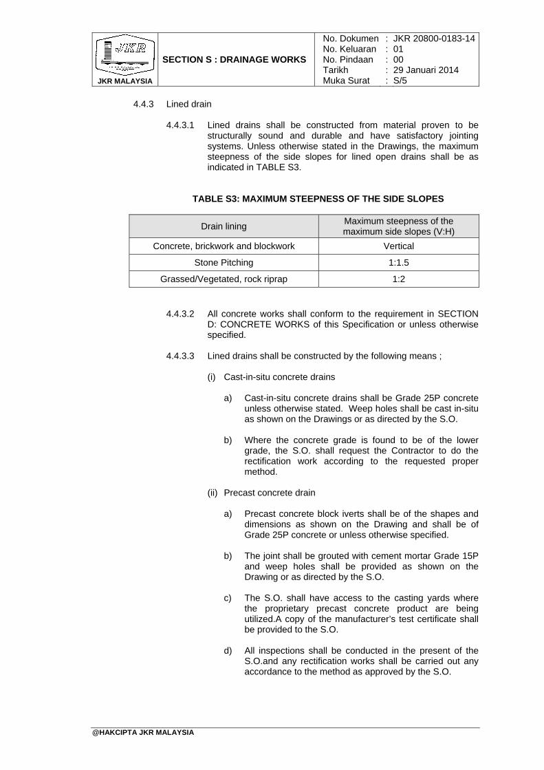
JKR MALAYSIA
SECTION S : DRAINAGE WORKS
No. DokumenNo. KeluaranNo. PindaanTarikhMuka Surat
: : : : :
JKR 20800-0183-1401 00 29 Januari 2014 S/5
@HAKCIPTA JKR MALAYSIA
4.4.3 Lined drain
4.4.3.1 Lined drains shall be constructed from material proven to be structurally sound and durable and have satisfactory jointing systems. Unless otherwise stated in the Drawings, the maximum steepness of the side slopes for lined open drains shall be as indicated in TABLE S3.
TABLE S3: MAXIMUM STEEPNESS OF THE SIDE SLOPES
Drain lining Maximum steepness of the maximum side slopes (V:H)
Concrete, brickwork and blockwork Vertical
Stone Pitching 1:1.5
Grassed/Vegetated, rock riprap 1:2
4.4.3.2 All concrete works shall conform to the requirement in SECTION D: CONCRETE WORKS of this Specification or unless otherwise specified.
4.4.3.3 Lined drains shall be constructed by the following means ;
(i) Cast-in-situ concrete drains
a) Cast-in-situ concrete drains shall be Grade 25P concrete unless otherwise stated. Weep holes shall be cast in-situ as shown on the Drawings or as directed by the S.O.
b) Where the concrete grade is found to be of the lower
grade, the S.O. shall request the Contractor to do the rectification work according to the requested proper method.
(ii) Precast concrete drain
a) Precast concrete block iverts shall be of the shapes and
dimensions as shown on the Drawing and shall be of Grade 25P concrete or unless otherwise specified.
b) The joint shall be grouted with cement mortar Grade 15P and weep holes shall be provided as shown on the Drawing or as directed by the S.O.
c) The S.O. shall have access to the casting yards where the proprietary precast concrete product are being utilized.A copy of the manufacturer’s test certificate shall be provided to the S.O.
d) All inspections shall be conducted in the present of the S.O.and any rectification works shall be carried out any accordance to the method as approved by the S.O.
JKR MALAYSIA
SECTION S : DRAINAGE WORKS
No. DokumenNo. KeluaranNo. PindaanTarikhMuka Surat
: : : : :
JKR 20800-0183-1401 00 29 Januari 2014 S/6
@HAKCIPTA JKR MALAYSIA
(iii) Cascade drains
Cascade drains shall be constructed from precast concrete drain units and laid stepping on a 150 mm thick bed of mass concrete of Grade 15P as shown on the Drawings or as approved by the S.O.
5. Subsoil Drain
5.1 This work shall include supply and installation of subsoil drains, constructed in accordance with these Specifications at locations as shown on the Drawing and/or as directed by the S.O.
5.2 Minimum gradient of 1:100 shall be provided for the drain to discharge into existing stormwater system, open drain, creek or pond in the area. The discharge shall not create an unwanted bog.
5.3 The lateral drain shall have a minimum slope of 1:100 to ensure water always flowing even though there are undulations and laid at 2 m spacing at 450 to the main pipes/collector drain.
6. Sumps
6.1 Sumps shall be constructed as accordance to the Drawing or as directed by the S.O. to facilitate changes in level and flow within a drainage system. All sumps shall be covered either by concrete slab or galvanized steel grating hinged to the seating frame on the sumps for safety purposes.
6.2 Unless otherwise as shown on the Drawings, sumps of depth less than 1.5 m (internal depth) shall be made up of brickwalls of minimum 225 mm thickness. Sump of depth (internal depth) more than 1.5 m shall use reinforced concrete Grade 20P.
7. Culverts
7.1 The work shall comprise of supply and installation of either reinforced concrete pipe culverts or precast box culverts, including the end treatment components such as headwall, wingwalls, aprons and sumps and channel protection works, all in accordance with these Specifications and details as shown on the Drawings.
7.2 Culvert Bedding
7.2.1 Type A bedding shall consist of Grade 20P concrete and complying with SECTION D: CONCRETE WORKS.
7.2.2 Type B bedding shall consist of clean, natural sand or gravelly sand of suitable gradation and quality with maximum particle size of not more than 12 mm.
7.3 Culvert Components
Culvert shall be constructed with barrel and end treatments including headwalls, endwalls, wingwalls, outlet protection, inlet improvement and debris control structures.
JKR MALAYSIA
SECTION S : DRAINAGE WORKS
No. DokumenNo. KeluaranNo. PindaanTarikhMuka Surat
: : : : :
JKR 20800-0183-1401 00 29 Januari 2014 S/7
@HAKCIPTA JKR MALAYSIA
7.4 Pipe Culverts
7.4.1 Pipe for culvert shall be of spun reinforced concrete of approved manufacturers complying with MS 881 and approved by the S.O. with spun concrete collars or spigot and socket type as shown on the Drawing.
7.4.2 The S.O. reserves the right to request for test certificates and to request for tests to be carried out on samples, all at the Contractor's own cost.
7.5 Precast Box Culverts
7.5.1 Box culverts shall be of precast concrete of approved manufacturer
complying with MS 1293 or any equivalent alternative acceptable and approved by the S.O.
7.5.2 Unless otherwise shown on the Drawings, the box shall be capable of withstanding a proof load test of 112.5 kN applied over an area of 320 mm x 320 mm at any position on the cover slab. The S.O. reserves the right to call for test certificates on the concrete boxes supplied.
7.5.3 Individual sections of the box shall be rejected because of such defects specified herein before for pipe culverts.
7.5.4 Precast box culverts shall be laid on Type B bedding with layer of crushed aggregate of maximum particle size not exceeding 50 mm as shown on the Drawings or directed by the S.O.
7.5.5 The maximum gap between each culvert shall not be more than 13 mm and the difference in level shall less than 3 mm. The gap shall be filled with cement mortar (1:3) with smooth finished.
7.5.6 To ensure uniform bearing, a layer of cement grout shall be spread along the top of the walls of the invert where the lid shall sit.
8. On-site Detention Pond
8.1 On-site detention (OSD) pond shall be constructed in accordance to the Drawings and conform to the requirements of MSMA.
8.2 Unless otherwise stated in the Drawings, the side slopes of basins shall not be steeper than 1 (V): 6 (H). Fence and warning signs shall be provided.
8.3 The construction of detention pond shall include the system components at the inlet, storage and outlet zone to cater outflow discharges without causing adverse effects on downstream properties.
8.4 Maintenance shall be done periodically or as and when the silt has accumulated to half of the pond height.

JKR MALAYSIA
SECTION S : DRAINAGE WORKS
No. DokumenNo. KeluaranNo. PindaanTarikhMuka Surat
: : : : :
JKR 20800-0183-1401 00 29 Januari 2014 S/8
@HAKCIPTA JKR MALAYSIA
BLANK PAGE
TABLE OF CONTENTS
SECTION T: SIGNAGE WORKS
PAGE
@HAKCIPTA JKR MALAYSIA
1. General 2. Copper Plating 3. Aluminium 4. Paint Finish 5. Screen Printing Works 6. Vinyl Graphic Stickers 7. Stainless Steel 8. Acrylic 9. Installation And Fixing Works 10. Labeling For Registration Of Immoveable Asset
Components
T/1 T/2 T/2 T/2 T/3 T/3 T/3 T/3 T/3 T/4

JKR MALAYSIA
SECTION T : SIGNAGE WORKS
No. DokumenNo. Keluaran No. Pindaan Tarikh Muka Surat
: : : : :
JKR 20800-0183-1401 00 29 Januari 2014 T/1
@HAKCIPTA JKR MALAYSIA
1. General
1.1 All interior architectural signage shall be of acrylic plastic as approved by the S.O. unless otherwise specified in the Drawings. All panel sign surfaces shall be flat and smooth, constructed to remain flat under installed conditions within tolerance of plus or minus 1 mm measured diagonally.
1.2 All signage works shall comply with the regulatory requirements currently enforced
and shall comply with MS 1184: Universal Design and Accessibility in The Built Environment - CP and Government Immoveable Asset Code System (Sistem Kod Aset Tak Alih - SKATA) as referred to sub-section 10.
1.3 Unless otherwise stated in the Drawings, the panel and lettering size, profiles and
dimensional requirements of interior panel signage shall be as follows: 1.3.1 The standard thickness of cast-acrylic matt clear sheets shall be not less
than 4 mm.
1.3.2 Raised lettering and graphic symbols shall be of 0.8 mm thickness obtained by using acrylic applique and chemically welded to sign panels.
1.3.3 The type of panel material and size of letterings shall be as indicated in the Schedule of Signage prepared by the manufacturer to the S.O.’s approval.
1.4 Graphic content and style of signage shall be in accordance with the Schedule of
Signage, Shop Drawings and comply with the requirements indicated below: 1.4.1 Panel material shall be acrylic with machine-routed raised copy applied to
surface of panel, along with “raster-method” Grade 2 braille beads, or pictograms and other artwork to be reverse applied vinyl or silk-screened process in colours as indicated.
1.4.2 For background colours, provide Pantone Matching System (PMS) coloured
coatings, including inks and paints, that are recommended by acrylic manufacturer for optimum adherence to surface, and that are non-fading for application intended.
1.4.3 Raised copy shall be machine routed copy, provide manufacturer’s full
range of solid to applique colours to the S.O.’s approval.
1.5 Location, accessories and mounting positions of signs shall comply with MS 1184, manufacturer’s recommendations and as approved by the S.O.
1.6 Wall mounted panel signs shall be mounted to wall surfaces using methods
indicated below:
(i) Vinyl-tape mounting: use double-sided very high bond (VHB) tape to adhere signs to smooth, non-porous surfaces.
(ii) Silicone-adhesive mounting: Use liquid-silicone adhesive recommended by manufacturer to attach signs to porous, irregular, or vinyl-coated surfaces. Use double-sided foam tape to hold sign in position until silicone adhesive has fully cured.
(iii) Mechanical fasteners: Use non-removable mechanical fasteners placed through pre-drilled holes in sign face, or through shim plate. Use proper anchors at masonry walls as recommended by manufacturer. Attach sign panel to shim plate using vinyl-tape method as described above.
JKR MALAYSIA
SECTION T : SIGNAGE WORKS
No. DokumenNo. Keluaran No. Pindaan Tarikh Muka Surat
: : : : :
JKR 20800-0183-1401 00 29 Januari 2014 T/2
@HAKCIPTA JKR MALAYSIA
(iv) Where signs are scheduled or indicated to be mounted on glass, to provide matching acrylic back plate at reverse-side of glass to conceal mounting materials.
(v) After installation, soiled sign surfaces shall be cleaned and protected from damage.
1.7 During the Contractor’s drawings preparation phase, the Contractor shall provide full
size mock-up samples of each type as required for inspection and subsequent approval by the S.O.
2. Copper Plating
2.1 Surface preparation of the copper plate is to be done before plating process. Cleaning process should include, degreasing, spray washing, immersion washing, stripping and or coating removal. Copper plate is to be pre-treated to receive plating treatment. Thickness of copper plating is to be of minimum 3-5 µm. All copper plating should be a thick film coating with excellent levelling to cover all surface irregularities to improve the general aesthetics.
2.2 Where grainy texture is required, the copper plate should be allowed to run in copper sulphate bath or copper cyanide based solution bath for a longer period.
3. Aluminium 3.1 Aluminium sign panels shall be preferably supported by extruded aluminium
extrusions for both internal and external signs complying with the requirements of MS 2289: Aluminium and Aluminium Alloy - Extruded Shapes.
3.2 Aluminium sheets where otherwise stated for construction shall be of minimum 3 mm thick with welded angles for support. The sub-contractor is to ensure that no tin-canning or deflection effect on the sign-face. Where tin-canning effect appears on the sign face, the nominated sub-contractor is to remove and replace the sign panel.
3.3 Aluminium sheets used shall comply with the requirements of MS 2040: Aluminium
and Aluminium Alloys - Sheets and Coiled Sheets - Specification. The alloy selected will be of a temper suitable for cutting.
3.4 Where signs required more than one standard size aluminium panel, the jointing shall be performed in accordance to BS 1473 by using rivets or screws with welded angles to the main panels. The joint shall than be fine sand, smoothen to be flushed to be seen as one and no butt-line joint, division or separation is to be seen.
3.5 All aluminium sections shall be fabricated from aluminium alloy B6063-T5 complying with the requirements of MS 2289: Aluminium and Aluminium Alloy-Extruded Shapes.
3.6 The aluminium shall be electronically anodized in matte finish for etched aluminium
required for the fire door sign.
4. Paint Finish Unless otherwise specified, all painting works shall be carried out as specified in SECTION O: PAINTING WORKS.
JKR MALAYSIA
SECTION T : SIGNAGE WORKS
No. DokumenNo. Keluaran No. Pindaan Tarikh Muka Surat
: : : : :
JKR 20800-0183-1401 00 29 Januari 2014 T/3
@HAKCIPTA JKR MALAYSIA
5. Screen Printing Works 5.1 Applications of screen-printing works shall be in accordance to the Specification
Drawings. The Contractor shall ensure high accuracy in registration and workmanship.
5.2 Silkscreen ink shall be of two (2) pack-serical poly-screen with Ultra Violet protective agents against colour fading. All finished screen printed text or graphics shall be coated with a layer of 2-pack polyurethane clear coat matte finish.
6. Vinyl Graphic Stickers
6.1 Unless otherwise specified in the Drawings and Specifications, vinyl graphic stickers shall be used as recommended by the manufacturer and approved by the S.O.
6.2 Unless otherwise specified in the Drawings, all illuminated graphics shall be of
translucent graphic films and non-illuminated signs shall be translucent opaque graphic films as approved by the S.O.
6.3 All vinyl graphics shall be precision cut by computers with no jagged edge. Minimum
performance of vinyl stickers shall be to the approval of the S.O.
7. Stainless Steel
7.1 Stainless steel shall be austenitic, non-magnetic, using grade 304 or 316 to BS EN 10088 and BS 1449 Part 2 for plate, sheet and strip and BS 970 where relevant. Stainless steel plate and component with hairline finish for all internal signs shall be of grade 304 4B.
7.2 Stainless steel plate and component for all external signs shall be of marine grade
316 with alloy addition of molybdenum to prevent specific forms of corrosion. 7.3 Stainless steel fasteners, bolts, screws, bolts, washers and other fixing components
shall be of Grade A2 or Grade A4 to BS EN ISO 3506.
8. Acrylic 8.1 Acrylic used for the external signage shall be of high impact acrylic. Extruded acrylic
shall not be acceptable. The Contractor shall comply with the required thickness of the acrylic as shown on the Drawings.
9. Installation And Fixing Works
9.1 The Contractor shall submit a works programme and method statements for the installation of all internal and external signs. The Contractor is to include in their method statement on safety processes, measures to be taken and procedures while erecting the external signs.
9.2 Unless otherwise shown on the Drawings, all base plates for external signs shall be
galvanized steel plates with drawings and calculation certified by P.E.
JKR MALAYSIA
SECTION T : SIGNAGE WORKS
No. DokumenNo. Keluaran No. Pindaan Tarikh Muka Surat
: : : : :
JKR 20800-0183-1401 00 29 Januari 2014 T/4
@HAKCIPTA JKR MALAYSIA
10. Labeling For Registration Of Immoveable Asset Components
10.1 The code and format for labelling of components shall be as stipulated in the Government’s: (i) Immoveable Asset Code System (Sistem Kod Aset Tak Alih – SKATA); and (ii) Immoveable Asset Data Collection Guidelines (Garis Panduan
Pengumpulan Data Aset Tak Alih – PeDATA).
10.2 All labels for the registration of the asset components shall comply with the regulatory requirements currently enforced and shall comply with the relevant International and/or Malaysian Standards.
10.3 Labels for the assets must be durable and withstand exposure to extreme conditions
such as chemicals, temperature, weather, oils and detergents. The labels must also be able to withstand the rigour of cleaning schedule, maintenance and repairs.
10.4 Unless otherwise stated in the Drawings, minimum requirements for asset
component labels shall be as follows:
(i) Normal Condition – vinyl stickers. (ii) Extreme Condition - steel / aluminium plate.
10.5 Asset component labels shall be affixed to the asset in a position that is easily
accessible for readability while the asset is in normal operating position (Refer to PeDATA).
10.6 Labels shall be located on clean, smooth, flat surfaces where possible, and on
surfaces that provide direct visual access to a label scanner and its operator.