static mixers for water- and wastewater treatment · 2015-04-23 · figure 1: sulzer mixer smvtm,...
TRANSCRIPT
Static Mixers for Water- and WastewaterTreatment
Sulzer Chemtech
�
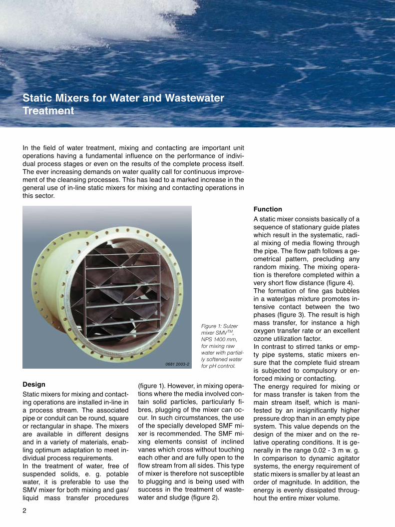
Figure 1: Sulzer mixer SMVTM, NPS 1400 mm, for mixing raw water with partial-ly softened water for pH control.
DesignStatic mixers for mixing and contact-ing operations are installed in-line in a process stream. The associated pipe or conduit can be round, square or rectangular in shape. The mixers are available in different designs and in a variety of materials, enab-ling optimum adaptation to meet in-dividual process requirements.In the treatment of water, free of suspended solids, e. g. potable water, it is preferable to use the SMV mixer for both mixing and gas/liquid mass transfer procedures
(figure 1). However, in mixing opera-tions where the media involved con-tain solid particles, particularly fi-bres, plugging of the mixer can oc-cur. In such circumstances, the use of the specially developed SMF mi-xer is recommended. The SMF mi-xing elements consist of inclined vanes which cross without touching each other and are fully open to the flow stream from all sides. This type of mixer is therefore not susceptible to plugging and is being used with success in the treatment of waste-water and sludge (figure �).
FunctionA static mixer consists basically of a sequence of stationary guide plates which result in the systematic, radi-al mixing of media flowing through the pipe. The flow path follows a ge-ometrical pattern, precluding any random mixing. The mixing opera-tion is therefore completed within a very short flow distance (figure 4).The formation of fine gas bubbles in a water/gas mixture promotes in-tensive contact between the two phases (figure 3). The result is high mass transfer, for instance a high oxygen transfer rate or an excellent ozone utilization factor.In contrast to stirred tanks or emp-ty pipe systems, static mixers en-sure that the complete fluid stream is subjected to compulsory or en-forced mixing or contacting.The energy required for mixing or for mass transfer is taken from the main stream itself, which is mani-fested by an insignificantly higher pressure drop than in an empty pipe system. This value depends on the design of the mixer and on the re-lative operating conditions. It is ge-nerally in the range 0.0� - 3 m w. g. In comparison to dynamic agitator systems, the energy requirement of static mixers is smaller by at least an order of magnitude. In addition, the energy is evenly dissipated throug-hout the entire mixer volume.
Static Mixers for Water and Wastewater Treatment
In the field of water treatment, mixing and contacting are important unit operations having a fundamental influence on the performance of indivi-dual process stages or even on the results of the complete process itself. The ever increasing demands on water quality call for continuous improve-ment of the cleansing processes. This has lead to a marked increase in the general use of in-line static mixers for mixing and contacting operations in this sector.
0681 2003-2
3
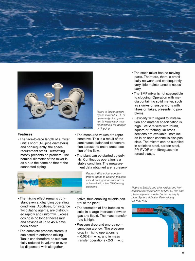
Features• The face-to-face length of a mixer
unit is short (1-5 pipe diameters) and consequently, the space requirement small. Retrofitting mostly presents no problem. The nominal diameter of the mixer is as a rule the same as that of the connected piping.
• The mixing effect remains con-stant even at changing operating conditions. Additives, for instance flocculating agents, are distribut-ed rapidly and uniformly. Excess dosing is no longer necessary and savings of up to 45% have been shown.
• The complete process stream is subjected to enforced mixing. Tanks can therefore be substan-tially reduced in volume or even be dispensed with altogether.
• The measured values are repre-sentative. This is a result of the continuous, balanced concentra-tion across the entire cross-sec-tion of the flow.
• The plant can be started up quik-kly. Continuous operation is a stable condition. The measure-ment data obtained are represen-
tative, thus enabling reliable con-trol of the plant.
• The formation of fine bubbles re-sults in a large interface between gas and liquid. The mass transfer rate is high.
• Pressure drop and energy con-sumption are low. The pressure drop in mixing operations is < 0.0�-� m w. g. and in mass transfer operations <�-3 m w. g.
• The static mixer has no moving parts. Therefore, there is practi-cally no wear, and consequently very little maintenance is neces-sary.
• The SMF mixer is not susceptible to clogging. Operation with me-dia containing solid matter, such as slurries or suspensions with fibres or flakes, presents no pro-blems.
• Flexibility with regard to installa-tion and material specification is high. Static mixers with round, square or rectangular cross- sections are available. Installati-on in an open channel is also pos-sible. The mixers can be supplied in stainless steel, carbon steel, PP, PVDF or in fibreglass rein-forced plastic.
Figure 4: Bubble bed with vertical and hori-zontal Sulzer mixer SMV-12 NPS 50 mm and phase separation in the horizontal empty pipe. System air/water. Flow velocity 0.5 m/s. m/s.
Figure 1: Sulzer polypro-pylene mixer SMF-PP of open design for opera-tion in wastewater treat-ment without the danger of clogging.
Figure 3: Blue colour concen-trate is added to water in the pipe axis. A homogeneous mixture is achieved with a few SMV mixing elements.
0692 2735
0691 2726-4
06
85
2019
-1
4
1
2 3
54
6
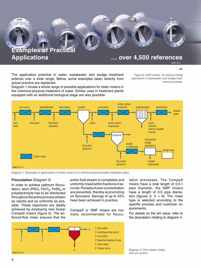
pH control destabilization flocculation clarifier ozonizationactive carbon treatment sedimentation disinfection
treated water
acidbase
flocculent flocculent(polymer)
ozone active carbonsuspension
ozonechlorinechlorine dioxidefluorine
thickener
flocculent(polymer)
flocculent(polymer)
sludgeconditioning
mechanicalsludgedewatering
sludge cake
treatedwastewater
1 Raw water
2 Acid/base/lime slurry
3 Flocculent
4 Reaction/sediment tank
5 Clear water
6 Sludge slurry
Flocculation (Diagram �)In order to achieve optimum floccu-lation, alum (PAC), FeCI3, FeS04 or polyelectrolyte has to be distributed throughout the entire process stream as rapidly and as uniformly as pos-sible. These objectives are ideally achieved by employing new Sulzer CompaX mixers (figure 5). The en-forced-flow mixer ensures that the
entire fluid stream is completely and uniformly mixed within fractions of se-conds. Pockets of over-concentration are prevented, thereby economizing on flocculent. Savings of up to 45% have been achieved in practice.
CompaX or SMF mixers are nor-mally recommended for floccu-
Diagram 2: Flocculation stage with pH control.
Diagram 1: Examples of applications of static mixers in a chemical-physical water treatment plant.
Examples of Practical Applications … over 4,500 references
The application potential in water, wastewater and sludge treatment extends over a wide range. Below, some examples taken directly from actual practice are explained.Diagram 1 shows a whole range of possible applications for static mixers in the chemical-physical treatment of water. Similar uses in treatment plants equipped with an additional biological stage are also possible.
lation processes. The CompaX mixers have a total length of 0,5-1 pipe diameter, the SMF mixers have a length of �-5 pipe diame-ters (figures �, 5 + 6). The mixer type is selected according to the specific process and customer re-quirements. For details on the pH value, refer to the description relating to diagram 4.
Figure 6: SMF-mixers for various mixing operations in wastewater and sludge treat-
ment processes.
Examples of Practical Applications … over 4,500 references
Sulzer mixer
4588 4051
0993 2711-1
0993 2712-1
5
1
3 4
6
8
9
10
8
11
9
7
52
1 Slurry
2 Flocculent concentrate (polymer) or prime solution
3 Dosing pump
4 Water for dilution
5 Static thickener
6 Decanter/centrifuge
7 Dewatering filter
8 Dewatered sludge
9 Filtrate
10 Thickened sludge
11 Clear water
Diagram 3: In-line dilution of flocculent and its addition to sludge prior to dewatering.
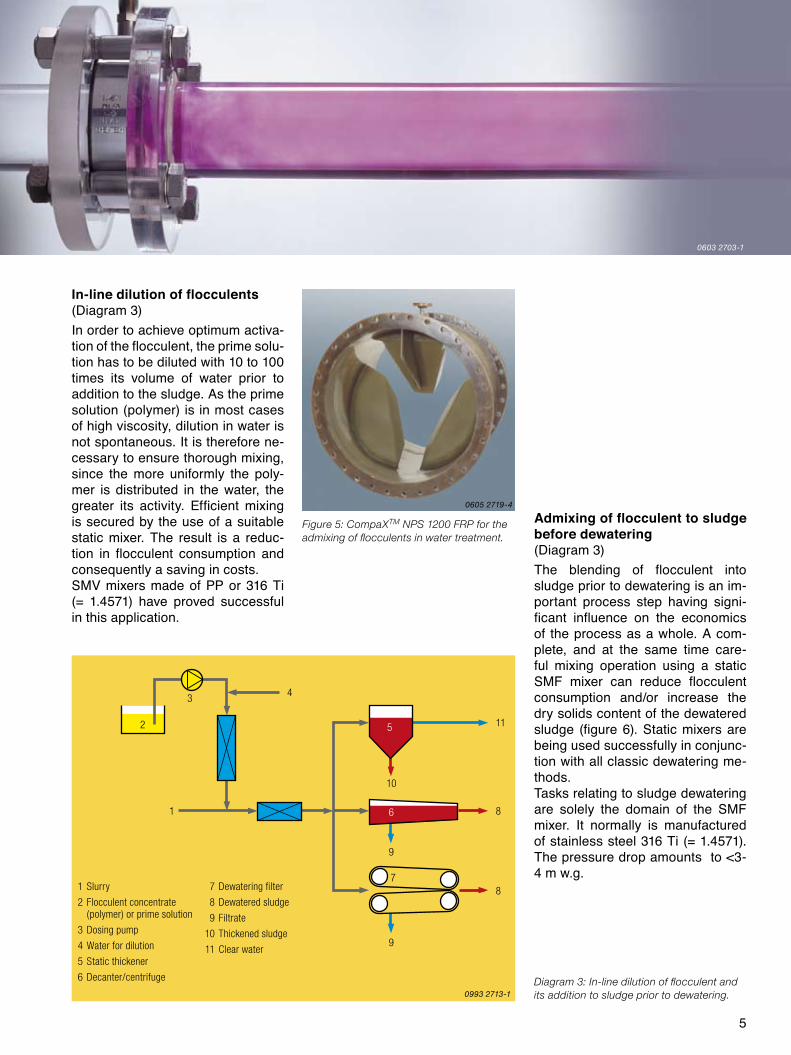
In-line dilution of flocculents(Diagram 3)In order to achieve optimum activa-tion of the flocculent, the prime solu-tion has to be diluted with 10 to 100 times its volume of water prior to addition to the sludge. As the prime solution (polymer) is in most cases of high viscosity, dilution in water is not spontaneous. It is therefore ne-cessary to ensure thorough mixing, since the more uniformly the poly-mer is distributed in the water, the greater its activity. Efficient mixing is secured by the use of a suitable static mixer. The result is a reduc-tion in flocculent consumption and consequently a saving in costs.SMV mixers made of PP or 316 Ti (= 1.4571) have proved successful in this application.
Admixing of flocculent to sludge before dewatering(Diagram 3)The blending of flocculent into sludge prior to dewatering is an im-portant process step having signi-ficant influence on the economics of the process as a whole. A com-plete, and at the same time care-ful mixing operation using a static SMF mixer can reduce flocculent consumption and/or increase the dry solids content of the dewatered sludge (figure 6). Static mixers are being used successfully in conjunc-tion with all classic dewatering me-thods.Tasks relating to sludge dewatering are solely the domain of the SMF mixer. It normally is manufactured of stainless steel 316 Ti (= 1.4571). The pressure drop amounts to <3-4 m w.g.
Figure 5: CompaXTM NPS 1200 FRP for the admixing of flocculents in water treatment.
0603 2703-1
0605 2719-4
0993 2713-1

6
3
1
2
6 5 4pH
7
2
1
3
4
ph control or neutralization (Diagram 4)Neutralization reactions general-ly take place within a short time, but under the condition that mi-xing of the reaction components in the process stream is effected quickly. This duty is well suited for the static mixer which enables the in-line neutralization reaction to be carried out directly in the pipe. Con-sequently, the volume of neutraliza-tion tanks can be greatly reduced or they can even be eliminated alto-gether. This space and energy sa-ving solution is being used with in-creasing success in water treatment plants (figure 7). Not only is it pos-sible to save on tanks but also a de-crease in energy cost and the ab-sence of maintenance work nor-mally attached to dynamic agitators lead to an overall reduction in run-ning costs.
In order to promote the mixing of the neutralization media (acid, base, lime slurry), they are prediluted di-rectly in-line in a supplementary small static mixer prior to being in-jected into the main stream (figure 8).
Downstream of static mixers, the measurement of representative da-ta is secured, an important factor for the reliable functioning of a control system. The probes for controlling the neutralization agent dosing are as a rule placed �-4 pipe diameters beyond the exit from the mixer.Neutralization is carried out using either SMV or SMF mixers of plas-tic or stainless steel. Their length is �-5 pipe diameters and the pres- sure drop lies in the range of 0.0�-� m w. g.
Admixing of disinfectant(Diagram 5)Prior to entering the distribution network, the treated drinking water undergoes the addition of a small amount of disinfectant or fluorine. In order to obtain the desired effect, the disinfectants have to be blended
uniformly throughout the entire wa-ter stream and, in the case of chlo-rines, in the shortest time possible.This operation is carried out with ease by SMV, SMI and/or CompaX mixers made of stainless steel. The pressure drop is about 0,0� – 1 m w. g. One of the main features of the CompaX mixers is short installa- tion length, the simple dosing nozz-le and the low pressure drop at the same efficient mixing performance. The CompaX mixers are nearly in-dependent of mixing ratio and also have excellent turn down ratios.
Figure 7: Mixing elements NPS 1000 mm and 1200 mm for admixing of flocculents and for adjustement of the pH value in a plant for treatment
of drinking water. The mixing elements made of stainless steel will be installed in cement-walled pipes. The rings position the mixers to protect
the pipe lining against damage.
1 Main water stream
2 Dilution water pump
3 Disinfectant dosing pump
4 To distribution network
1 Raw water
2 Neutralization medium (acid/base/lime slurry)
3 Neutralization feed tank
4 pH probe
5 Controller
6 Metering valve
7 Neutralized water
Diagram 4: pH control or neutralization. Diagram 5: Admixing of disinfectant.
0692 2745-2
0993 2715-10993 2714-1
7
2
3
1 4
21
3
5
4
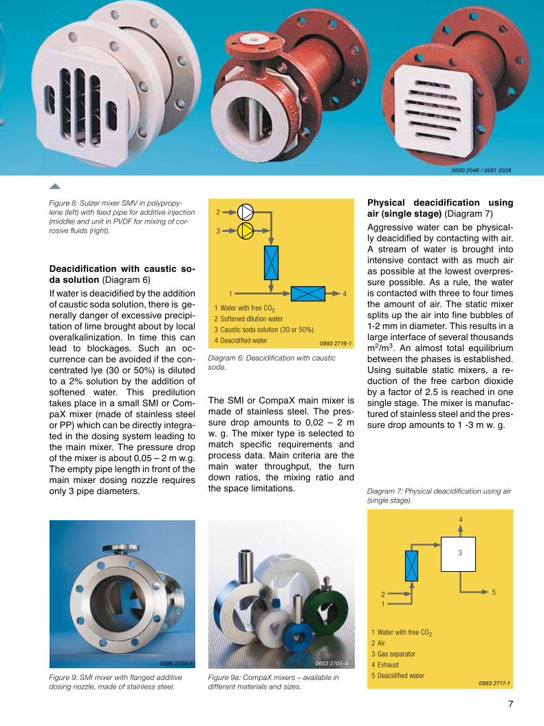
Deacidification with caustic so-da solution (Diagram 6)If water is deacidified by the addition of caustic soda solution, there is ge-nerally danger of excessive precipi-tation of lime brought about by local overalkalinization. In time this can lead to blockages. Such an oc-currence can be avoided if the con-centrated lye (30 or 50%) is diluted to a �% solution by the addition of softened water. This predilution takes place in a small SMI or Com-paX mixer (made of stainless steel or PP) which can be directly integra-ted in the dosing system leading to the main mixer. The pressure drop of the mixer is about 0,05 – � m w.g. The empty pipe length in front of the main mixer dosing nozzle requires only 3 pipe diameters.
The SMI or CompaX main mixer is made of stainless steel. The pres-sure drop amounts to 0,0� – � m w. g. The mixer type is selected to match specific requirements and process data. Main criteria are the main water throughput, the turn down ratios, the mixing ratio and the space limitations.
Figure 9: SMI mixer with flanged additive dosing nozzle, made of stainless steel.
Figure 9a: CompaX mixers – available in different materials and sizes.
Figure 8: Sulzer mixer SMV in polypropy-lene (left) with feed pipe for additive injection (middle) and unit in PVDF for mixing of cor-rosive fluids (right).
Physical deacidification using air (single stage) (Diagram 7)Aggressive water can be physical-ly deacidified by contacting with air. A stream of water is brought into intensive contact with as much air as possible at the lowest overpres- sure possible. As a rule, the water is contacted with three to four times the amount of air. The static mixer splits up the air into fine bubbles of 1-� mm in diameter. This results in a large interface of several thousands m�/m3. An almost total equilibrium between the phases is established. Using suitable static mixers, a re-duction of the free carbon dioxide by a factor of �.5 is reached in one single stage. The mixer is manufac-tured of stainless steel and the pres-sure drop amounts to 1 -3 m w. g.
1 Water with free CO2
2 Softened dilution water
3 Caustic soda solution (30 or 50%)
4 Deacidified water
1 Water with free CO2
2 Air
3 Gas separator
4 Exhaust
5 Deacidified water
Diagram 6: Deacidification with caustic soda.
Diagram 7: Physical deacidification using air (single stage).
0680 2046 / 0681 2038
0696 2704-1 0603 2705-4
0993 2717-1
0993 2716-1
8
4
1
3
53
2 1 2
4 4
2
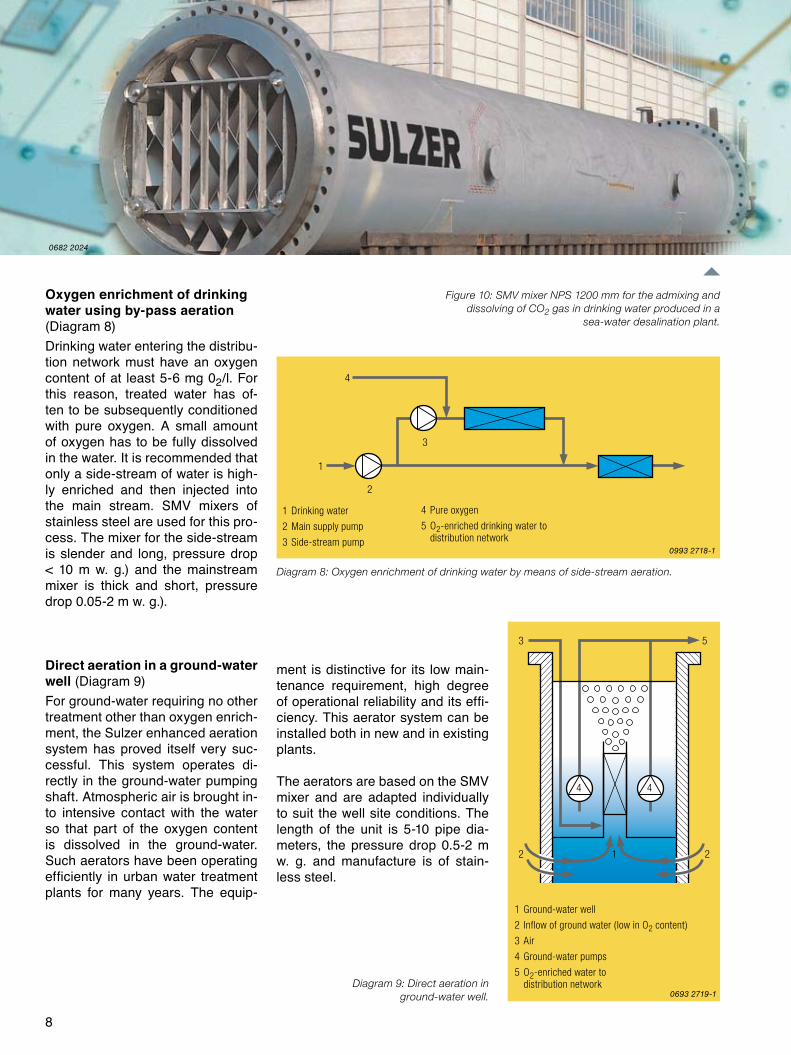
Oxygen enrichment of drinking water using by-pass aeration (Diagram 8)Drinking water entering the distribu-tion network must have an oxygen content of at least 5-6 mg 0�/l. For this reason, treated water has of-ten to be subsequently conditioned with pure oxygen. A small amount of oxygen has to be fully dissolved in the water. It is recommended that only a side-stream of water is high-ly enriched and then injected into the main stream. SMV mixers of stainless steel are used for this pro-cess. The mixer for the side-stream is slender and long, pressure drop < 10 m w. g.) and the mainstream mixer is thick and short, pressure drop 0.05-� m w. g.).
Direct aeration in a ground-water well (Diagram 9)For ground-water requiring no other treatment other than oxygen enrich-ment, the Sulzer enhanced aeration system has proved itself very suc-cessful. This system operates di-rectly in the ground-water pumping shaft. Atmospheric air is brought in-to intensive contact with the water so that part of the oxygen content is dissolved in the ground-water. Such aerators have been operating efficiently in urban water treatment plants for many years. The equip-
ment is distinctive for its low main-tenance requirement, high degree of operational reliability and its effi-ciency. This aerator system can be installed both in new and in existing plants.
The aerators are based on the SMV mixer and are adapted individually to suit the well site conditions. The length of the unit is 5-10 pipe dia-meters, the pressure drop 0.5-� m w. g. and manufacture is of stain-less steel.
1 Drinking water
2 Main supply pump
3 Side-stream pump
4 Pure oxygen
5 O2-enriched drinking water to distribution network
Diagram 8: Oxygen enrichment of drinking water by means of side-stream aeration.
Figure 10: SMV mixer NPS 1200 mm for the admixing and dissolving of CO2 gas in drinking water produced in a
sea-water desalination plant.
Diagram 9: Direct aeration in ground-water well.
1 Ground-water well
2 Inflow of ground water (low in O2 content)
3 Air
4 Ground-water pumps
5 O2-enriched water to distribution network
0682 2024
0993 2718-1
0693 2719-1
9
1
2
3 4
2
1
3
5
4
6
7
5
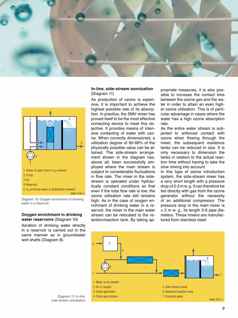
Oxygen enrichment in drinking water reservoirs (Diagram 10)Aeration of drinking water directly in a reservoir is carried out in the same manner as in groundwater well shafts (Diagram 9).
In-line, side-stream ozonization (Diagram 11)As production of ozone is expen-sive, it is important to achieve the highest possible rate of its absorp-tion. In practice, the SMV mixer has proved itself to be the most effective contacting device to meet this ob-jective. It provides means of inten-sive contacting of water with ozo-ne. When correctly dimensioned, a utilization degree of 90-99% of the physically possible value can be at-tained. The side-stream arrange-ment shown in the diagram has, above all, been successfully em-ployed where the main stream is subject to considerable fluctuations in flow rate. The mixer in the side-stream is operated under hydrau-lically constant conditions so that even if the total flow rate is low, the ozone utilization rate still remains high. As in the case of oxygen en-richment of drinking water in a re-servoir, the mixer in the main water stream can be relocated to the re-tention/reaction tank. By taking ap-
propriate measures, it is also pos-sible to increase the contact time between the ozone gas and the wa-ter in order to attain an even high-er ozone utilisation. This is of parti-cular advantage in cases where the water has a high ozone absorption rate.As the entire water stream is sub-jected to enforced contact with ozone when flowing through the mixer, the subsequent residence tanks can be reduced in size. It is only necessary to dimension the tanks in relation to the actual reac-tion time without having to take the slow mixing into account.In this type of ozone introduction system, the side-stream mixer has a very short length with a pressure drop of �-3 m w. g. It can therefore be fed directly with gas from the ozone generator without the necessity of an additional compressor. The pressure drop in the main mixer is < � m w. g., its length 3-6 pipe dia-meters. These mixers are manufac-tured from stainless steel.
1 Inflow of water (low in O2 content)
2 Pump
3 Air
4 Reservoir
5 O2-enriched water to distribution network
1 Water to be treated
2 Air or oxygen
3 Ozone generator
4 Ozone gas mixture
5 Side-stream pump
6 Retention/reaction tank
7 Ozonized water
Diagram 10: Oxygen enrichment of drinking water in a reservoir.
Diagram 11: In-line, side-stream ozonization
0993 2720-1
0993 2721-1
10
1
2 3
4 5
6
7 8
1
2
3 4
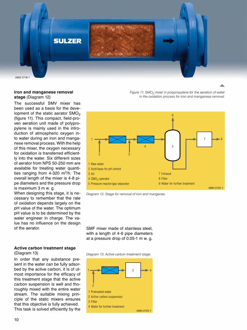
Iron and manganese removal stage (Diagram 1�)The successful SMV mixer has been used as a basis for the deve-lopment of the static aerator SMO� (figure 11). This compact, field-pro-ven aeration unit made of polypro-pylene is mainly used in the intro-duction of atmospheric oxygen in-to water during an iron and manga-nese removal process. With the help of this mixer, the oxygen necessary for oxidation is transferred efficient-ly into the water. Six different sizes of aerator from NPS 50-�50 mm are available for treating water quanti-ties ranging from 4-3�0 m3/h. The overall length of the mixer is 4-8 pi-pe diameters and the pressure drop is maximum 3 m w. g.When designing this stage, it is ne-cessary to remember that the rate of oxidation depends largely on the pH value of the water. The optimum pH value is to be determined by the water engineer in charge. The va-lue has no influence on the design of the aerator.
Active carbon treatment stage (Diagram 13)In order that any substance pre-sent in the water can be fully adsor-bed by the active carbon, it is of ut-most importance for the efficacy of this treatment stage that the active carbon suspension is well and tho-roughly mixed with the entire water stream. The suitable mixing prin-ciple of the static mixers ensures that this objective is fully achieved.This task is solved efficiently by the
SMF mixer made of stainless steel, with a length of 4-6 pipe diameters at a pressure drop of 0.05-1 m w. g.
1 Raw water
2 Acid/base for pH control
3 Air
4 SMO2 operator
5 Pressure reactor/gas separator
Diagram 12: Stage for removal of iron and manganes.
7 Exhaust
8 Filter
9 Water for further treatment
1 Pretreated water
2 Active carbon suspension
3 Filter
4 Water for further treatment
Diagram 13: Active carbon treatment stage.
Figure 11: SMO2 mixer in polypropylene for the aeration of water in the oxidation process for iron and manganese removal.
0993 2722-1
0993 2723-1
0692 2718-1
11
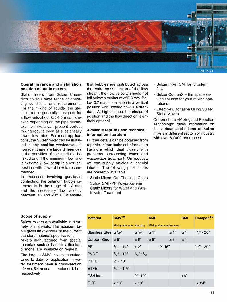
Material SMVTM SMF SMI CompaXTM
Mixing elements Housing Mixing elements Housing
Stainless Steel ≥ 1/�” ≥ 1/�” ≥ 1” ≥ 1” ≥ 1” 1/�” - �0”
Carbon Steel ≥ 6” ≥ 6” ≥ 6” ≥ 6” ≥ 1”
PP 1/�” - 14” ≥ 2” 2”-16” 1/�” - �0”
PVDF 1/�” - 10” 1/�”-11/�
PTFE �” - 10”
ETFE 1/�” - 11/�”
CS/Liner 2”- 10” ≥6”
GKF ≥ 10” ≥ 10” ≥ 24”
Operating range and installation position of static mixersStatic mixers from Sulzer Chem-tech cover a wide range of opera-ting conditions and requirements. For the mixing of liquids, the sta-tic mixer is generally designed for a flow velocity of 0.5-1.5 m/s. How- ever, depending on the pipe diame-ter, the mixers can present perfect mixing results even at substantially lower flow rates. For most applica-tions, the Sulzer mixer can be instal-led in any position whatsoever. If, however, there are large differences in the densities of the media to be mixed and if the minimum flow rate is extremely low, setup in a vertical position with upward flow is recom-mended.In processes involving gas/liquid contacting, the optimum bubble di-ameter is in the range of 1-� mm and the necessary flow velocity between 0.5 and � m/s. To ensure
that bubbles are distributed across the entire cross-section of the flow stream, the flow velocity should not fall below a minimum of 0.3 m/s. Be-low 0.7 m/s, installation in a vertical position with upward flow is a stan-dard. At higher rates, the choice of position and the flow direction is en-tirely optional.
Available reprints and technical information literatureFurther details can be obtained from reprints or from technical information literature which deal closely with problems surrounding water and wastewater treatment. On request, we can supply articles of special interest. The following publications are presently available:• Static Mixers Cut Chemical Costs• Sulzer SMF-PP Polypropylene
Static Mixers for Water and Was-tewater Treatment
Scope of supplySulzer mixers are available in a va-riety of materials. The adjacent ta-ble gives an overview of the current standard material specifications.Mixers manufactured from special materials such as hastelloy, titanium or monel are available on request.The largest SMV mixers manufac-tured to date for application in wa-ter treatment have a cross-section of 4m x 6.4 m or a diameter of 1.4 m, respectively.
• Sulzer mixer SMI for turbulent flow
• Sulzer CompaX – the space sa-ving solution for your mixing ope-rations
• Effective Ozonation Using Sulzer Static Mixers
Our brochure «Mixing and Reaction Technology“ gives information on the various applications of Sulzer mixers in different sectors of industry with over 60‘000 references.
0685 2019-1
0603 2532-2
23.83.06.40-IV.06-50 - Printed in Switzerland
HeadquartersSulzer Chemtech AGP.O. Box 65CH-8404 Winterthur, SwitzerlandTelephone +41 (0)52 262 67 20Fax +41 (0)52 262 00 69E-mail [email protected] www.sulzerchemtech.com North and South AmericaSulzer Chemtech USA, Inc.4019 S. Jackson StreetUS-Tulsa, OK 74107Telephone +1 (918) 445-6614Fax +1 (918) 445-6670
Asia PacificSulzer Chemtech Pte. Ltd.Regional Headquarters25 International Business Park#03-28 German CentreSG-60 99 16 SingaporeTelephone +65 6863 75 60Fax +65 6861 15 16
Sulzer Chemtech Ltd, a member of the Sulzer Corporation, with head-quarters in Winterthur, Switzerland, is active in the field of process engi-neering and employs some 1500 persons worldwide.
Sulzer Chemtech is represented in all important industrial countries and sets standards in the field of mass transfer and static mixing with its ad-vanced and economical solutions.
The activity program comprises:
• Process components such as trays, structured and random pa-ckings, internals for separation columns and reaction technology
• Engineering services for separation and reaction technology such as optimizing energy consumption, plant optimization studies, pre-engineering for governmental approval, basic engineering
• Separation and purification of organic chemicals by means of crys-tallization and membranes
• Mixing and reaction technology with static mixers
• Tower field services
Distributed by: