state of california department of transportation technical ... · state of california department of...
TRANSCRIPT
STATE OF CALIFORNIA DEPARTMENT OF TRANSPORTATION TECHNICAL REPORT DOCUMENTATION PAGE TR0003 (REV. 10/98) 1. REPORT NUMBER CEEMF005
2. GOVERNMENT ASSOCIATION NUMBER
3. RECIPIENT’S CATALOG NUMBER
4. TITLE AND SUBTITLE
LONG-TERM STRUCTURAL PERFORMANCE
MONITORING OF BRIDGES
Hardware Maintenance and, Long-term Data Collection/Analysis
5. REPORT DATE
June, 2011
6. PERFORMING ORGANIZATION CODE
UC Irvine
7. AUTHOR(S)
Maria Q. Feng, Yoshio Fukuda, Xuming Deng, Yuqing Guan, and
Hugo C Gomez
8. PERFORMING ORGANIZATION REPORT NO.
9. PERFORMING ORGANIZATION NAME AND ADDRESS
Civil and Environmental Engineering E4120 Engineering Gateway
University of California, Irvine
Irvine, CA 92697-2175
10. WORK UNIT NUMBER
11. CONTRACT OR GRANT NUMBER
59A0701
12. SPONSORING AGENCY AND ADDRESS
California Department of Transportation
Division of Research and Innovation, MS-83
1227 O Street
Sacramento CA 95814
13. TYPE OF REPORT AND PERIOD COVERED
Final Report
14. SPONSORING AGENCY CODE
15. SUPPLEMENTAL NOTES
16. ABSTRACT
In this project a description of the maintenance of the sensor monitoring systems installed on three California
highway bridges is presented. The monitoring systems consist of accelerometers, strain gauges, pressure sensors,
and displacement sensors which were installed on three highway bridges over the last decade: the Jamboree Rd.
Overcrossing, the West St. On-Ramp, and the Fairview Rd. Overcrossing. Based on the measured sensor data
under traffic and seismic excitations, the research team established baseline models of the bridges, and
developed methodologies for structural health monitoring and damage assessment. The measured sensor data
have provided better understanding of behaviors of highway bridges under traffic and seismic structural
performance database. In total, 15 journal papers resulting from this Caltrans-sponsored project were published
and 1 more is being evaluated for possible publication. In order to improve the efficiency and reliability of data
acquisition, the research team has repaired and maintained the existing data acquisition systems. Specifically, the
following major tasks has been carried out: (1) maintenance of the sensors, data loggers, and power suppliers;
(2) establishment of a reliable Internet-based remote access to the data loggers; (3) development of software for
remote control of the data loggers through Internet; (4) data collection of the three instrumented bridges under
controlled and uncontrolled traffic excitations, as well as seismic excitations; and (5) data analysis and baseline
updating by taking into consideration of influence of weather and traffic.
17. KEY WORDS
Structural health monitoring, long-term monitoring,
database, monitoring system, data-logger, Internet-
based remote access, model updating, concrete bridge
18. DISTRIBUTION STATEMENT No restrictions. This document is available to the
public through the National Technical Information
Service, Springfield, VA 22161
19. SECURITY CLASSIFICATION (of this report)
Unclassified 20. NUMBER OF PAGES
27
21. PRICE
Final Report Submitted to The California Department of Transportation
Under Contract No: 59A0701
LONG-TERM STRUCTURAL PERFORMANCE MONITORING OF BRIDGES
Hardware Maintenance and, Long-term Data Collection/Analysis
By
Maria Q. Feng, Professor.
Yoshio Fukuda, Post-doctoral Researcher
Xuming Deng, Visitor Scholar
Yuqing Guan, Visitor Scholar
and
Hugo C Gomez, Graduate Student Researcher
Department of Civil & Environmental Engineering University of California, Irvine
June, 2011

i
DISCLAIMER STATEMENT This document is disseminated in the interest of information exchange. The contents of this report reflect the views of the authors who are responsible for the facts and accuracy of the data presented herein. The contents do not necessarily reflect the official views or policies of the State of California or the Federal Highway Administration. This publication does not constitute a standard, specification or regulation. This report does not constitute an endorsement by the Department of any product described herein.
For individuals with sensory disabilities, this document is available in Braille, large print, audiocassette, or compact disk. To obtain a copy of this document in one of these alternate formats, please contact: the Division of Research and Innovation, MS-83, California Department of Transportation, P.O. Box 942873, Sacramento, CA 94273-0001.
LONG-TERM STRUCTURAL PERFORMANCE
MONITORING OF BRIDGES
Hardware Maintenance and, Long-term Data Collection/Analysis
Final Report Submitted to the California Department of Transportation under Contract No: 59A0701
By
Maria Q. Feng, Professor.
Yoshio Fukuda, Post-doctoral Researcher
Xuming Deng, Visitor Scholar
Yuqing Guan, Visitor Scholar
and
Hugo C Gomez, Graduate Student Researcher
Department of Civil & Environmental Engineering University of California, Irvine
June, 2011
SUMMARY In this project a description of the maintenance of the sensor monitoring systems installed on three California highway bridges is presented. The monitoring systems consist of accelerometers, strain gauges, pressure sensors, and displacement sensors which were installed on three highway bridges over the last decade: the Jamboree Rd. Overcrossing, the West St. On-Ramp, and the Fairview Rd. Overcrossing. Based on the measured sensor data under traffic and seismic excitations, the research team established baseline models of the bridges, and developed methodologies for structural health monitoring and damage assessment. The measured sensor data have provided better understanding of behaviors of highway bridges under traffic and seismic structural performance database. In total, 15 journal papers resulting from this Caltrans-sponsored project were published and 1 more is being evaluated for possible publication. In order to improve the efficiency and reliability of data acquisition, the research team has repaired and maintained the existing data acquisition systems. Specifically, the following major tasks has been carried out: (1) maintenance of the sensors, data loggers, and power suppliers; (2) establishment of a reliable Internet-based remote access to the data loggers; (3) development of software for remote control of the data loggers through Internet; (4) data collection of the three instrumented bridges under controlled and uncontrolled traffic excitations, as well as seismic excitations; and (5) data analysis and baseline updating by taking into consideration of influence of weather and traffic.
iv
List of Figures
Page
Figure 1. Three Instrumented Bridges. ........................................................................................... 1 Figure 2. Sensors on Three Instrumented Bridges. ......................................................................... 2 Figure 3. Access to the monitoring system inside the box girder at WSO Bridge. ........................ 4 Figure 4. Internet-based remote access to data-logger(recorder). ................................................... 5 Figure 19. Comparison between vibration records at channel 3 before (OLD) and after (NEW) the replacement of the data-logger at WSO. ................................................................................... 6 Figure 5. Remote Real-Time acceleration data recorded at JRO. ................................................... 7 Figure 6. Response acceleration time-histories recorded at WSO Bridge. ..................................... 8 Figure 7. Response acceleration time-histories recorded at WSO Bridge during controlled tests using a Caltrans water-truck. .......................................................................................................... 9 Figure 8. Water truck driven over the WSO bridge during the traffic controlled tests. ................. 9 Figure 9. Response acceleration recorded at JRO and WSO Bridge during Yucaipa Earthquake........................................................................................................................................................ 10 Figure 10. Frequency dependence on earthquake peak ground acceleration (PGA) at WSO. ..... 11 Figure 11. Strain measurements at WSO during controlled traffic vibration test. Remarks: L denotes the position of the truck, R denotes strain meter, T denotes transverse position of truck........................................................................................................................................................ 11 Figure 12. Variation of JRO natural identified natural frequencies (Soyoz and Feng 2009). ...... 12 Figure 13. Decreasing of the first and second natural frequencies at JRO (Soyoz and Feng 2009)........................................................................................................................................................ 13 Figure 14. Long-term monitoring of WSO Bridge natural frequencies. ....................................... 13 Figure 15. Superstructure stiffness degradation at JRO Bridge. ................................................... 14 Figure 16. Superstructure and column stiffness degradation at WSO Bridge. ............................. 14 Figure 17. Replacement of the data-logger at FROO and WSO ................................................... 17 Figure 18. Scheme of the new data-logger ................................................................................... 17
List of Tables Page
Table 1 Seismic records obtained at WSO Bridge ........................................................................ 10 Table 2 Yearly Average Bridge Natural Frequencies ................................................................... 15
v
Table of Contents
Page
TECHNICAL REPORT PAGE ………………………………………………………………... i
DISCLAMER ………………………………………………………………………………….. ii
SUMMARY ………………………………………………………………………………….... iii
LIST OF FIGURES …………………………………………………………………………… iv
LIST OF TABLES ……………………………………………………………………………... iv
1. Maintenance of Monitoring Systems ....................................................................................... 1
1.1 Jamboree Rd. Overcrossing.............................................................................................. 1
1.2 West St. On-Ramp ............................................................................................................ 3
1.3 Fairview Road On-Ramp Overcrossing ........................................................................... 4
2. Internet-based remote access to the data loggers ..................................................................... 5
3. Hardware Maintenance ............................................................................................................ 6
4. Improvement of Data quality ................................................................................................... 6
5. Software for remote control of the data recorders through Internet ........................................ 7
6. Data collection under controlled and uncontrolled traffic excitations and under seismic excitations ....................................................................................................................................... 8
7. Data analysis, database development, and baseline updating ............................................... 12
8. Conclusions ........................................................................................................................... 16
Appendix A ................................................................................................................................... 17
A.1 Replacement of Data-loggers ......................................................................................... 17
Bibliography ................................................................................................................................. 19
1. M Under thacceleromdevices wOvercros5 Corridobridges a
For the umaintain Based onbridges wmonitorindocumenhighway This sectthree brid
1.1 JaThe Jamstressed plongest sbearings In total, 2002, at be out ofdisplacem A 16-chaautomati3 was se
Maintenan
e previous Cmeters, strainwas conductessing on Rt. or, and the Fare shown in
ultimate succthe monitor
n the collectwere establing results h
nt. The mebridge struc
tion providesdges.
amboree Rmboree Rd.
post-tensionspan is 152 on both abu
15 accelerostrategicallyf order. Therment sensor
annel data lcally by eart
et up for trig
nce of Mo
Caltrans suppn gauges, pred on three h261 of the E
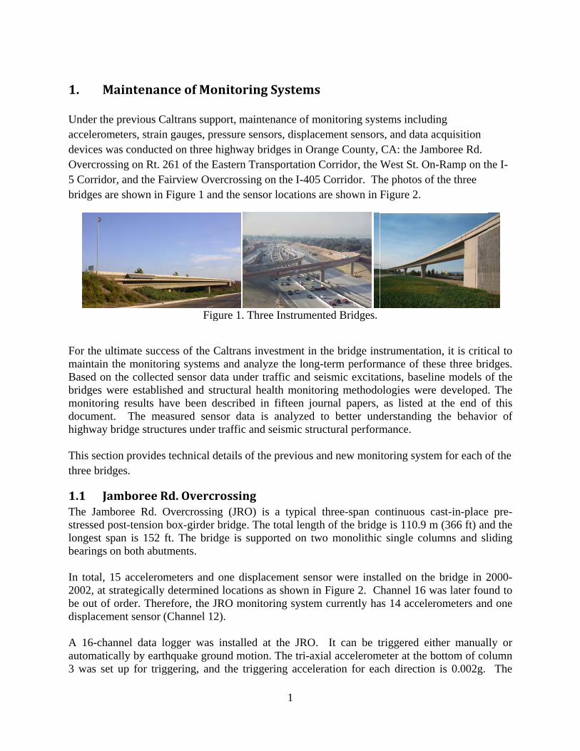
Fairview Oven Figure 1 an
Fig
cess of the Cring systemsted sensor dashed and str
have been deasured sensctures under
s technical d
Rd. OvercrOvercrossin
n box-girder ft. The brid
utments.
meters and y determinedrefore, the J(Channel 12
logger was thquake grouggering, and
onitoring S
port, maintenressure sensohighway brid
Eastern Transercrossing on
nd the sensor
gure 1. Three
Caltrans inves and analyzata under traructural hea
described in sor data is traffic and s
details of the
rossing ng (JRO) is
bridge. The dge is suppo
one displacd locations aJRO monitor2).
installed at und motion.d the trigger
1
Systems
nance of moors, displacemdges in Oransportation Cn the I-405 Cr locations ar
e Instrument
estment in thze the long-taffic and seialth monitori
fifteen jouranalyzed to
seismic struc
previous an
a typical thtotal length
orted on two
ement sensoas shown in Fring system
the JRO. The tri-axiaring accelera
onitoring sysment sensornge County,
Corridor, the Corridor. Thre shown in
ted Bridges.
he bridge insterm performismic excitating methodornal papers, o better undctural perform
nd new moni
hree-span cof the bridg
o monolithic
or were instaFigure 2. Ccurrently ha
It can be tal acceleromation for eac
tems includirs, and data aCA: the JamWest St. Onhe photos ofFigure 2.
strumentatiomance of thetions, baseliologies were
as listed atderstanding mance.
itoring system
ontinuous cge is 110.9 mc single colu
alled on theChannel 16 was 14 acceler
triggered eitmeter at the b
ch direction
ing acquisition mboree Rd. n-Ramp on thf the three
on, it is criticese three brine models o
e developedt the end ofthe behavio
m for each o
cast-in-placem (366 ft) anumns and sl
e bridge in 2was later fourometers and
ther manualbottom of con is 0.002g.
he I-
cal to idges. of the . The f this or of
of the
pre-nd the liding
2000-und to d one
lly or olumn
The
power sutime strefailure dumonitorin
Two poincampus,
upply to theet light AC ue to unexpng system w
nt-to-point afor real-tim
monitoringpower sourc
pected eventwere replaced
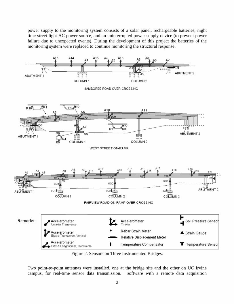
Figure 2.
antennas weme sensor d
g system conce, and an uts). During td to continue
. Sensors on
ere installed,data transm
2
nsists of a suninterruptedthe developme monitoring
Three Instru
, one at the ission. So
solar panel, d power suppment of this
g the structur
umented Bri
bridge site ftware with
rechargeablply device (ts project theral response.
idges.
and the othh a remote
e batteries, to prevent pe batteries o.
her on UC Idata acquis
night power of the
Irvine sition
3
capability was developed by the proposal team at UC Irvine based on the platform of TS-Terminal. The newly developed software was installed by the research team on a computer on UCI campus, and functions as a server that remotely controls the data logger at the bridge site, receives streaming data from the data logger, saves them in the computer and buffers them for Internet publication. However, due to the difficulty in securing the line of sight between the two antennas (located more than 6 miles apart), the wireless communication is often interrupted by the interferences on the path. Therefore further development of the wireless connection is needed. In summary, the power supply and the data transmission do not work properly at the JRO and need to be replaced or upgraded.
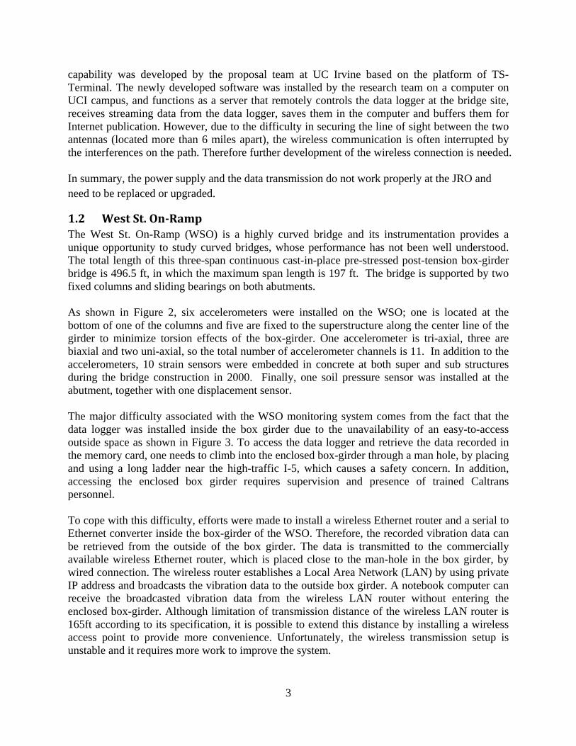
1.2 West St. OnRamp The West St. On-Ramp (WSO) is a highly curved bridge and its instrumentation provides a unique opportunity to study curved bridges, whose performance has not been well understood. The total length of this three-span continuous cast-in-place pre-stressed post-tension box-girder bridge is 496.5 ft, in which the maximum span length is 197 ft. The bridge is supported by two fixed columns and sliding bearings on both abutments. As shown in Figure 2, six accelerometers were installed on the WSO; one is located at the bottom of one of the columns and five are fixed to the superstructure along the center line of the girder to minimize torsion effects of the box-girder. One accelerometer is tri-axial, three are biaxial and two uni-axial, so the total number of accelerometer channels is 11. In addition to the accelerometers, 10 strain sensors were embedded in concrete at both super and sub structures during the bridge construction in 2000. Finally, one soil pressure sensor was installed at the abutment, together with one displacement sensor. The major difficulty associated with the WSO monitoring system comes from the fact that the data logger was installed inside the box girder due to the unavailability of an easy-to-access outside space as shown in Figure 3. To access the data logger and retrieve the data recorded in the memory card, one needs to climb into the enclosed box-girder through a man hole, by placing and using a long ladder near the high-traffic I-5, which causes a safety concern. In addition, accessing the enclosed box girder requires supervision and presence of trained Caltrans personnel. To cope with this difficulty, efforts were made to install a wireless Ethernet router and a serial to Ethernet converter inside the box-girder of the WSO. Therefore, the recorded vibration data can be retrieved from the outside of the box girder. The data is transmitted to the commercially available wireless Ethernet router, which is placed close to the man-hole in the box girder, by wired connection. The wireless router establishes a Local Area Network (LAN) by using private IP address and broadcasts the vibration data to the outside box girder. A notebook computer can receive the broadcasted vibration data from the wireless LAN router without entering the enclosed box-girder. Although limitation of transmission distance of the wireless LAN router is 165ft according to its specification, it is possible to extend this distance by installing a wireless access point to provide more convenience. Unfortunately, the wireless transmission setup is unstable and it requires more work to improve the system.
4
Figure 3. Access to the monitoring system inside the box girder at WSO Bridge.
In summary, the WSO monitoring system needs a reliable wireless communications solution for convenient and frequent data acquisition without accessing the data logger located inside the box girder.
1.3 Fairview Road OnRamp Overcrossing The Fairview Road On-Ramp Over-crossing (FROO) is a four-span continuous cast-in-place pre-stressed post-tension box-girder bridge. The total length of the bridge is 224.0 m (734.9 ft.), in which the longest span is 59.5m (195.2 ft). The bridge is supported on three monolithic single columns and sliding bearings on both abutments. As shown in Figure 2, a total of 21 channels of accelerometers were installed on the bridge super and substructures. In addition to the accelerometers seven LVDT type strain meters were embedded in the bridge superstructure and three were embedded in one of the columns. Also, conventional resister type strain gauges were also embedded in the substructure. They are used to measure strain distribution in the reinforced concrete footing of the columns and to compare with those measured by the LVDT strain meters in the column. Two soil pressure sensors and one displacement sensor were also installed. Finally, three thermocouples were placed in the superstructure in span 1. One of them measures the outside temperature and the other two the inside temperature of the box girder. The previous data logger was unstable and unreliable. Therefore, a new 43-channel data logger was installed at the FROO. The sensor data are acquired by retrieving an SD memory card inside the data logger manually.
5
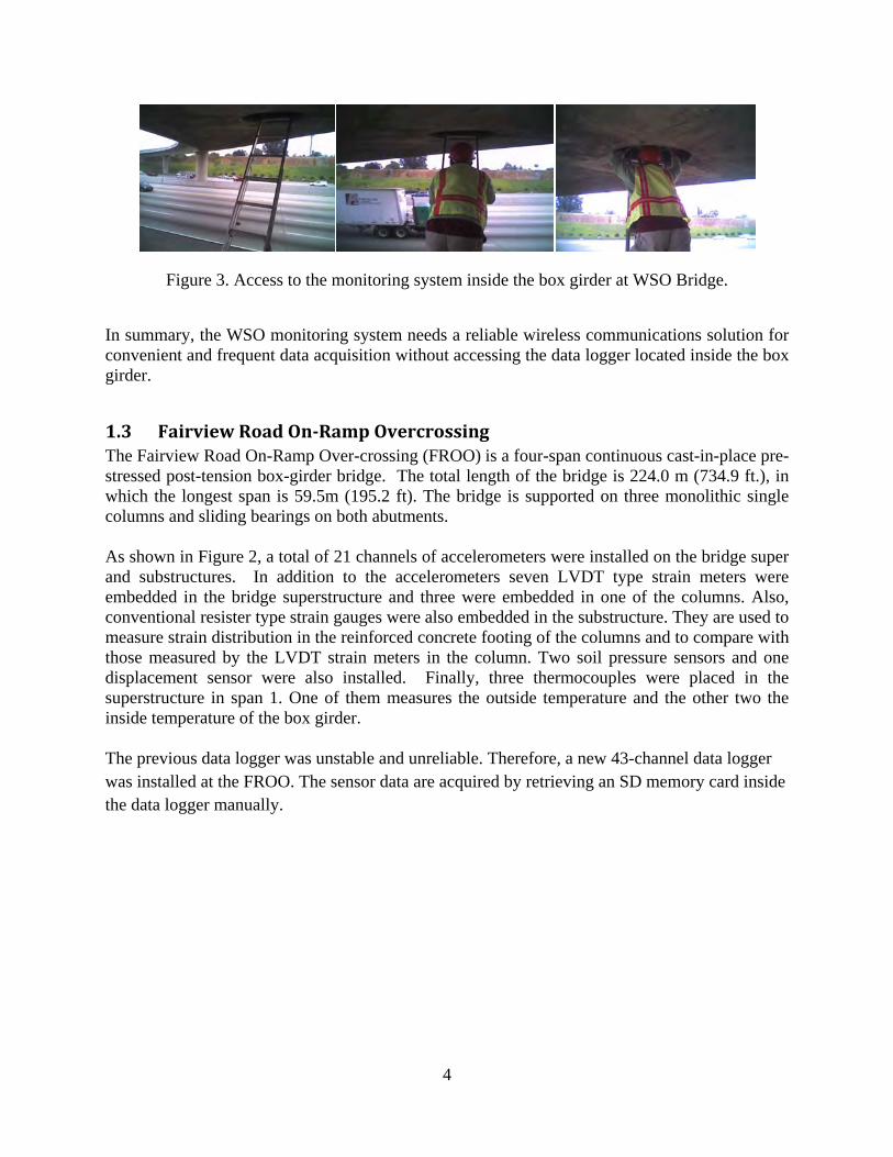
2. Internetbased remote access to the data loggers In order to improve the efficiency of long-term and frequent data acquisition, a more easy way to access data logger is needed and Internet accessible equipment setup can resolve this problem. The research team installed Internet-based remote accessible data logger at all of the three monitoring systems on the bridges. In particular, the access inside the box girder at the WSO is no longer required to retrieve the data which reduces the risk of accidents during the bridge monitoring. The research team contracted a commercial wireless Internet service for the remote data acquisition. This Internet-based remote access will enable the researchers at UC Irvine and engineers at Caltrans to stay connected to the monitoring system on the bridges, to schedule automated data acquisition, and to acquire sensor data in real time whenever needed. Figure 4 shows a basic scheme of the installed Internet-based remote access to the data-logger.
Figure 4. Internet-based remote access to data-logger(recorder).
6
3. Hardware Maintenance
At the Jamboree Bridge the power supply was checked and it was necessary to clean the solar panel and replace the batteries located under the superstructure. After maintenance of the power supply the research team replaced the data-logger. In order to change the data-logger the cables were replaced and the channels were re-ordered to make easier for post-processing data. Afterwards, the Internet-based remote access to the data logger was implemented.
At Fairview Bridge site, the research team checked all the cables before changing the data-logger. It was found the cables needed to be replaced. The new cables were installed using a reference table located at the bridge site. Then, the data-logger was replaced and the digital filter was implemented in order to get a better quality of the data. Afterwards, the Internet-based remote access to the data logger was installed.
Finally, the monitoring system at the West Street On Ramp Bridge was inspected. Although the data-logger was working properly a new data-logger was needed to improve the quality of the data. Also, an Internet-based remote access to the data logger was implemented in order to allow the data acquisition from the outside of the bridge.
4. Improvement of Data quality
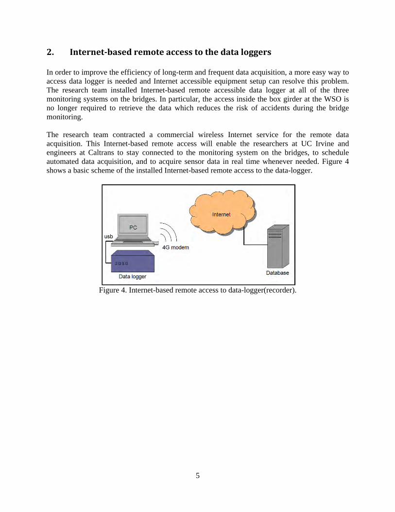
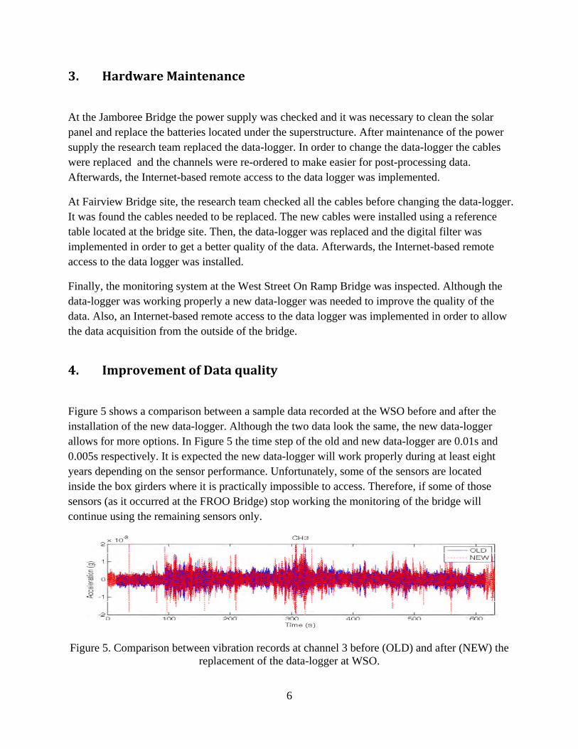
Figure 5 shows a comparison between a sample data recorded at the WSO before and after the installation of the new data-logger. Although the two data look the same, the new data-logger allows for more options. In Figure 5 the time step of the old and new data-logger are 0.01s and 0.005s respectively. It is expected the new data-logger will work properly during at least eight years depending on the sensor performance. Unfortunately, some of the sensors are located inside the box girders where it is practically impossible to access. Therefore, if some of those sensors (as it occurred at the FROO Bridge) stop working the monitoring of the bridge will continue using the remaining sensors only.
Figure 5. Comparison between vibration records at channel 3 before (OLD) and after (NEW) the replacement of the data-logger at WSO.
7
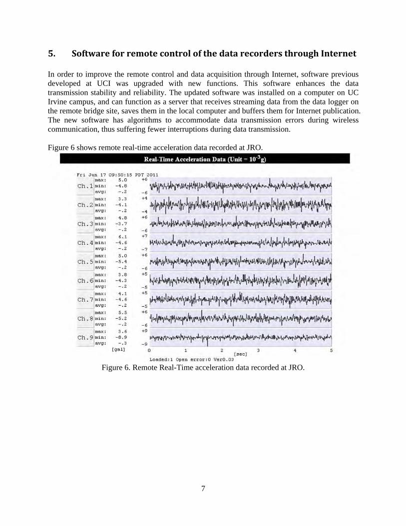
5. Software for remote control of the data recorders through Internet In order to improve the remote control and data acquisition through Internet, software previous developed at UCI was upgraded with new functions. This software enhances the data transmission stability and reliability. The updated software was installed on a computer on UC Irvine campus, and can function as a server that receives streaming data from the data logger on the remote bridge site, saves them in the local computer and buffers them for Internet publication. The new software has algorithms to accommodate data transmission errors during wireless communication, thus suffering fewer interruptions during data transmission. Figure 6 shows remote real-time acceleration data recorded at JRO.
Figure 6. Remote Real-Time acceleration data recorded at JRO.

6. Dexcitat An extendifferent enables ton the bchannels
Figure 8WSO Brspeeds an
Data colletions and
nsive data coloading co
the investigaridge dynamat the WSO
Figure 7
shows respridge, in whind alongside
ction und under se
ollection wasonditions incation of the vmic behavior
O Bridge und
7. Response a
ponse acceleich a heavy e different la
der controismic exc
s conducted cluding convehicle-bridgrs. Typical
der uncontrol
acceleration
eration time-truck, show
anes.
8
olled andcitations
since 2002.ntrolled and ge interactionresponse aclled traffic a
time-histori
-histories unwn in Figure
d uncontro
. The availabuncontrolle
n and furthecceleration tare shown in
ies recorded
nder control8, was driv
olled traf
ble data wered traffic exrmore the inime-historieFigure 7.
at WSO Bri
lled traffic even on the br
ffic
re recorded uxcitations.
nfluence of tres recorded
idge.
excitations aridge at diff
under This
raffic at 11
at the ferent
9
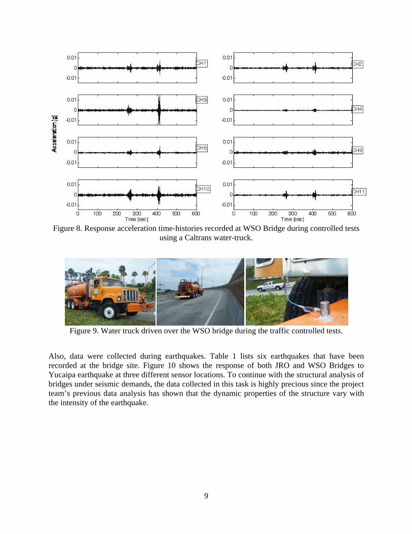
Figure 8. Response acceleration time-histories recorded at WSO Bridge during controlled tests
using a Caltrans water-truck.
Figure 9. Water truck driven over the WSO bridge during the traffic controlled tests.
Also, data were collected during earthquakes. Table 1 lists six earthquakes that have been recorded at the bridge site. Figure 10 shows the response of both JRO and WSO Bridges to Yucaipa earthquake at three different sensor locations. To continue with the structural analysis of bridges under seismic demands, the data collected in this task is highly precious since the project team’s previous data analysis has shown that the dynamic properties of the structure vary with the intensity of the earthquake.
10
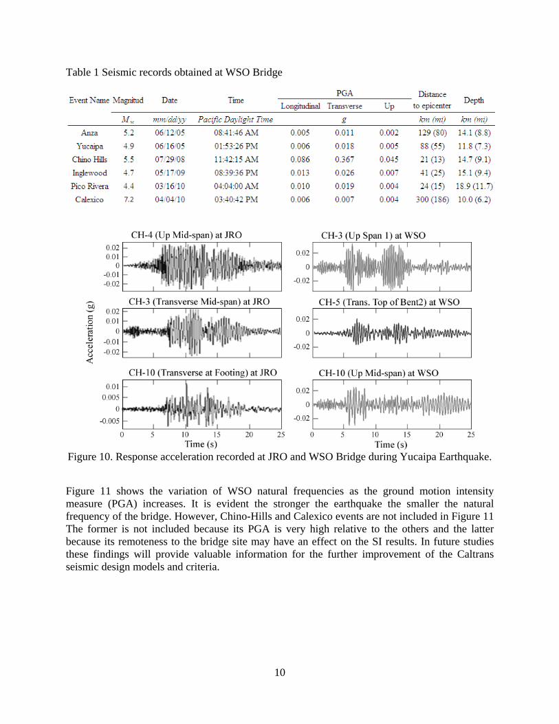
Table 1 Seismic records obtained at WSO Bridge
Figure 10. Response acceleration recorded at JRO and WSO Bridge during Yucaipa Earthquake.
Figure 11 shows the variation of WSO natural frequencies as the ground motion intensity measure (PGA) increases. It is evident the stronger the earthquake the smaller the natural frequency of the bridge. However, Chino-Hills and Calexico events are not included in Figure 11 The former is not included because its PGA is very high relative to the others and the latter because its remoteness to the bridge site may have an effect on the SI results. In future studies these findings will provide valuable information for the further improvement of the Caltrans seismic design models and criteria.
11
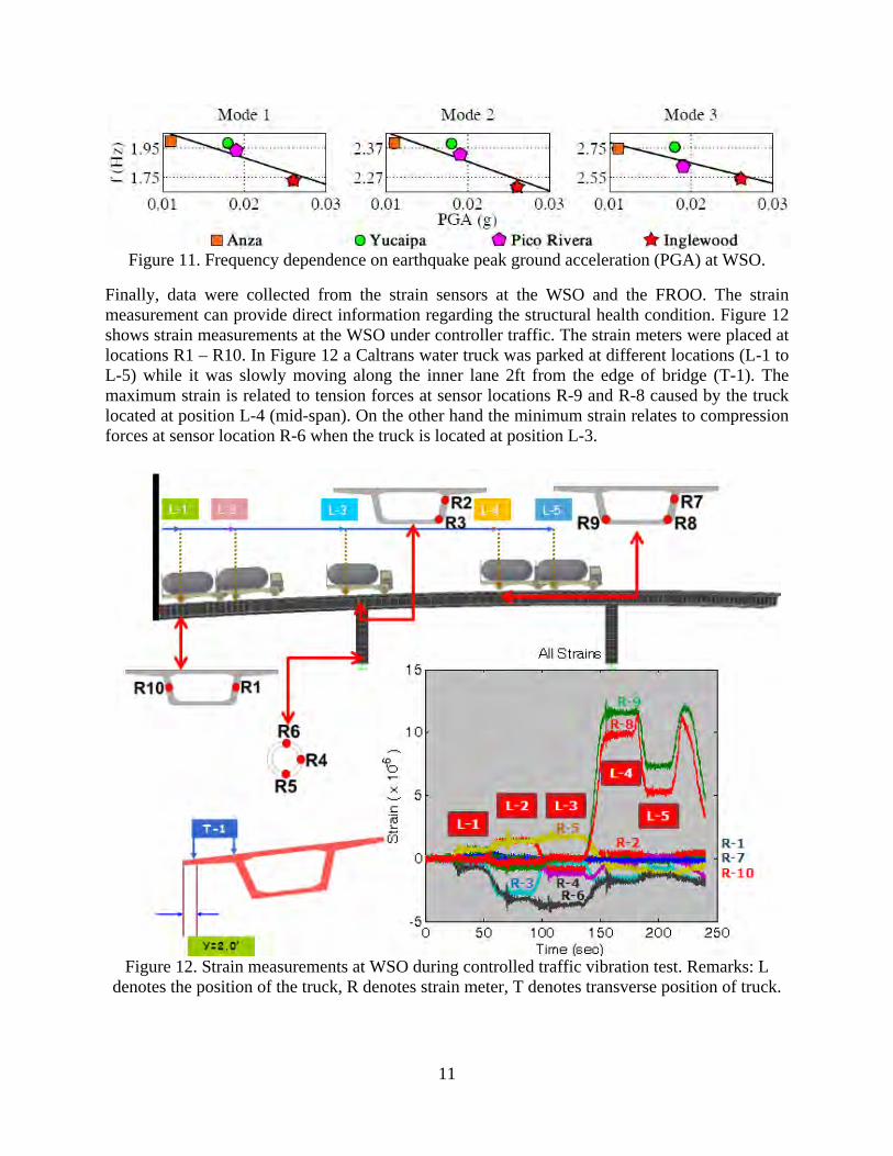
Figure 11. Frequency dependence on earthquake peak ground acceleration (PGA) at WSO.
Finally, data were collected from the strain sensors at the WSO and the FROO. The strain measurement can provide direct information regarding the structural health condition. Figure 12 shows strain measurements at the WSO under controller traffic. The strain meters were placed at locations R1 – R10. In Figure 12 a Caltrans water truck was parked at different locations (L-1 to L-5) while it was slowly moving along the inner lane 2ft from the edge of bridge (T-1). The maximum strain is related to tension forces at sensor locations R-9 and R-8 caused by the truck located at position L-4 (mid-span). On the other hand the minimum strain relates to compression forces at sensor location R-6 when the truck is located at position L-3.
Figure 12. Strain measurements at WSO during controlled traffic vibration test. Remarks: L
denotes the position of the truck, R denotes strain meter, T denotes transverse position of truck.
12
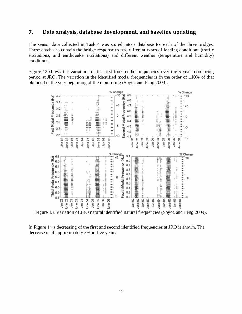
7. Data analysis, database development, and baseline updating The sensor data collected in Task 4 was stored into a database for each of the three bridges. These databases contain the bridge response to two different types of loading conditions (traffic excitations, and earthquake excitations) and different weather (temperature and humidity) conditions. Figure 13 shows the variations of the first four modal frequencies over the 5-year monitoring period at JRO. The variation in the identified modal frequencies is in the order of ±10% of that obtained in the very beginning of the monitoring (Soyoz and Feng 2009).
Figure 13. Variation of JRO natural identified natural frequencies (Soyoz and Feng 2009).
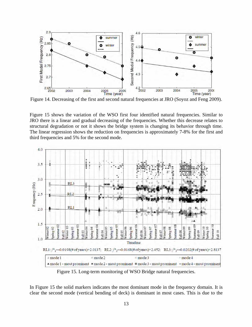
In Figure 14 a decreasing of the first and second identified frequencies at JRO is shown. The decrease is of approximately 5% in five years.
13
Figure 14. Decreasing of the first and second natural frequencies at JRO (Soyoz and Feng 2009).
Figure 15 shows the variation of the WSO first four identified natural frequencies. Similar to JRO there is a linear and gradual decreasing of the frequencies. Whether this decrease relates to structural degradation or not it shows the bridge system is changing its behavior through time. The linear regression shows the reduction on frequencies is approximately 7-8% for the first and third frequencies and 5% for the second mode.
Figure 15. Long-term monitoring of WSO Bridge natural frequencies.
In Figure 15 the solid markers indicates the most dominant mode in the frequency domain. It is clear the second mode (vertical bending of deck) is dominant in most cases. This is due to the
14
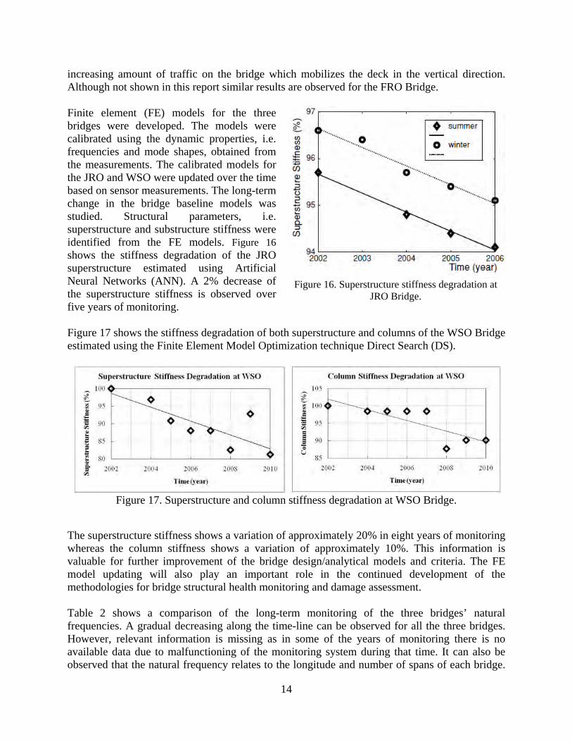
increasing amount of traffic on the bridge which mobilizes the deck in the vertical direction. Although not shown in this report similar results are observed for the FRO Bridge. Finite element (FE) models for the three bridges were developed. The models were calibrated using the dynamic properties, i.e. frequencies and mode shapes, obtained from the measurements. The calibrated models for the JRO and WSO were updated over the time based on sensor measurements. The long-term change in the bridge baseline models was studied. Structural parameters, i.e. superstructure and substructure stiffness were identified from the FE models. Figure 16 shows the stiffness degradation of the JRO superstructure estimated using Artificial Neural Networks (ANN). A 2% decrease of the superstructure stiffness is observed over five years of monitoring.
Figure 16. Superstructure stiffness degradation at
JRO Bridge.
Figure 17 shows the stiffness degradation of both superstructure and columns of the WSO Bridge estimated using the Finite Element Model Optimization technique Direct Search (DS).
Figure 17. Superstructure and column stiffness degradation at WSO Bridge.
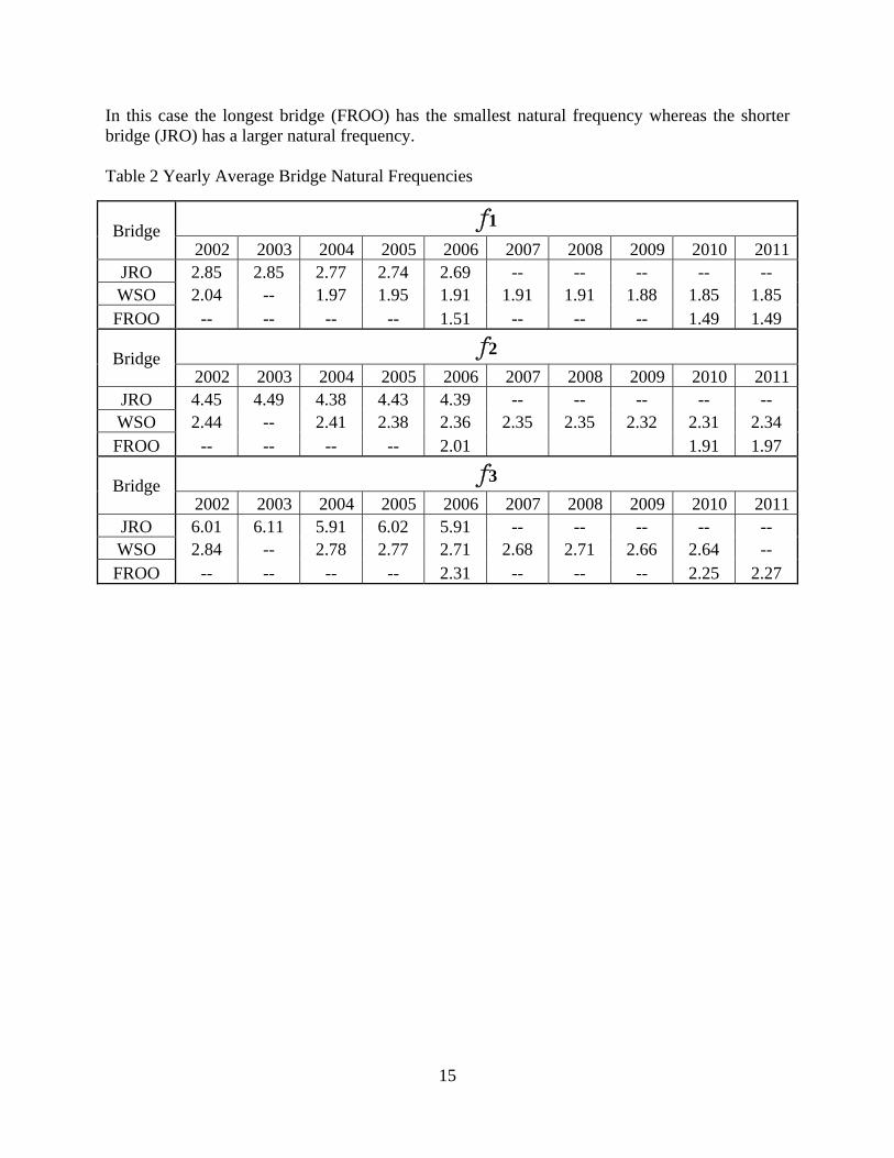
The superstructure stiffness shows a variation of approximately 20% in eight years of monitoring whereas the column stiffness shows a variation of approximately 10%. This information is valuable for further improvement of the bridge design/analytical models and criteria. The FE model updating will also play an important role in the continued development of the methodologies for bridge structural health monitoring and damage assessment. Table 2 shows a comparison of the long-term monitoring of the three bridges’ natural frequencies. A gradual decreasing along the time-line can be observed for all the three bridges. However, relevant information is missing as in some of the years of monitoring there is no available data due to malfunctioning of the monitoring system during that time. It can also be observed that the natural frequency relates to the longitude and number of spans of each bridge.
15
In this case the longest bridge (FROO) has the smallest natural frequency whereas the shorter bridge (JRO) has a larger natural frequency. Table 2 Yearly Average Bridge Natural Frequencies
Bridge f1
2002 2003 2004 2005 2006 2007 2008 2009 2010 2011 JRO 2.85 2.85 2.77 2.74 2.69 -- -- -- -- -- WSO 2.04 -- 1.97 1.95 1.91 1.91 1.91 1.88 1.85 1.85 FROO -- -- -- -- 1.51 -- -- -- 1.49 1.49
Bridge f2
2002 2003 2004 2005 2006 2007 2008 2009 2010 2011 JRO 4.45 4.49 4.38 4.43 4.39 -- -- -- -- -- WSO 2.44 -- 2.41 2.38 2.36 2.35 2.35 2.32 2.31 2.34 FROO -- -- -- -- 2.01 1.91 1.97
Bridge f3
2002 2003 2004 2005 2006 2007 2008 2009 2010 2011 JRO 6.01 6.11 5.91 6.02 5.91 -- -- -- -- -- WSO 2.84 -- 2.78 2.77 2.71 2.68 2.71 2.66 2.64 -- FROO -- -- -- -- 2.31 -- -- -- 2.25 2.27

16
8. Conclusions Maintenance of the monitoring system at three bridges (JRO, WSO, and FROO) is reported. New data-loggers enhance the quality of the recorded data which in turn allows for more accurate results of the post-processing. An Internet-Based remote data acquisition was installed at the three bridges as the new data-loggers allow the connection of a wireless device. This remote access allows for researchers and engineers to monitor the bridge dynamic properties and structural response without the need of going to the bridge site. From the datasets available at the three bridges a linear and gradual decrease of the lower identified natural frequencies is detected. This decrease is attributed to the aging of the structural system rather than any significant damage. FE models of the three bridges were developed and calibrated with the available measurements. The models are utilized to identify changes of the structural stiffness. For the JRO the superstructure stiffness decreases approximately 2% in five years of monitoring. In the case of WSO a decrease of the superstructure stiffness of approximately 20% in eight years of monitoring is detected whereas the column stiffness suffered 10% decrease in eight years. In future studies the FE models will be analyzed in more detail so the effect of stiffness reduction is studied. In addition other techniques will be applied to the data to clarify whether the change in frequencies can be utilized as an indicator of structure deterioration. In this manner engineers could potentially apply preventive maintenance before structural damage occurs. Finally, the data obtained from the strain gauge will be correlated with the health condition identified using the vibration measurement made by the accelerometers.
17
Appendix A
A.1 Replacement of Dataloggers
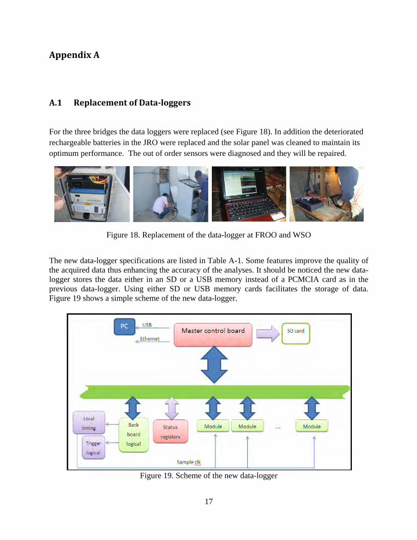
For the three bridges the data loggers were replaced (see Figure 18). In addition the deteriorated rechargeable batteries in the JRO were replaced and the solar panel was cleaned to maintain its optimum performance. The out of order sensors were diagnosed and they will be repaired.
Figure 18. Replacement of the data-logger at FROO and WSO
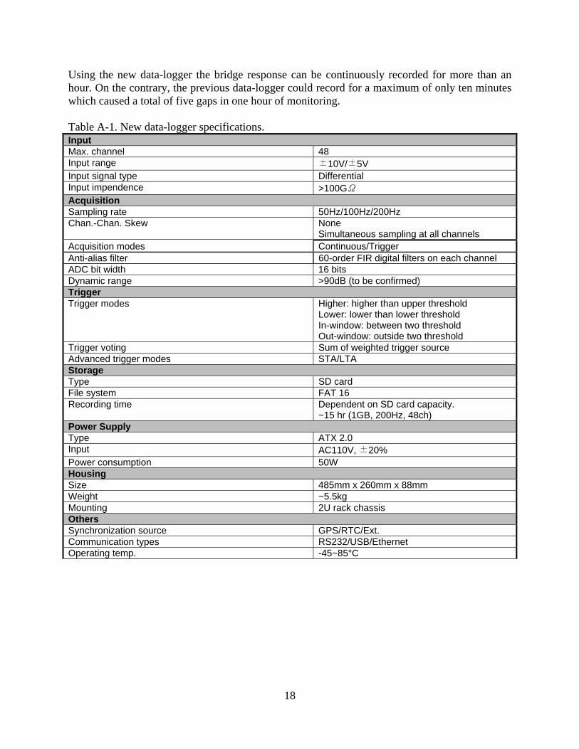
The new data-logger specifications are listed in Table A-1. Some features improve the quality of the acquired data thus enhancing the accuracy of the analyses. It should be noticed the new data-logger stores the data either in an SD or a USB memory instead of a PCMCIA card as in the previous data-logger. Using either SD or USB memory cards facilitates the storage of data. Figure 19 shows a simple scheme of the new data-logger.
Figure 19. Scheme of the new data-logger
18
Using the new data-logger the bridge response can be continuously recorded for more than an hour. On the contrary, the previous data-logger could record for a maximum of only ten minutes which caused a total of five gaps in one hour of monitoring. Table A-1. New data-logger specifications. Input Max. channel 48 Input range ±10V/±5V Input signal type Differential Input impendence >100GΩ Acquisition Sampling rate 50Hz/100Hz/200Hz Chan.-Chan. Skew None
Simultaneous sampling at all channels Acquisition modes Continuous/Trigger Anti-alias filter 60-order FIR digital filters on each channel ADC bit width 16 bits Dynamic range >90dB (to be confirmed) Trigger Trigger modes Higher: higher than upper threshold
Lower: lower than lower threshold In-window: between two threshold Out-window: outside two threshold
Trigger voting Sum of weighted trigger source Advanced trigger modes STA/LTA Storage Type SD card File system FAT 16 Recording time Dependent on SD card capacity.
~15 hr (1GB, 200Hz, 48ch) Power Supply Type ATX 2.0 Input AC110V, ±20% Power consumption 50W Housing Size 485mm x 260mm x 88mm Weight ~5.5kg Mounting 2U rack chassis Others Synchronization source GPS/RTC/Ext. Communication types RS232/USB/Ethernet Operating temp. -45~85°C
19
Bibliography
The list of publications under previous Caltrans support is given below:
1. Chen, Y. B. and Feng, M.Q., (2003). “Technique to improve the empirical mode decomposition in the Hilbert-Huang transform”, Journal of Earthquake Engineering and Engineering Vibration, Vol. 2, No. 1, pp 75-86.
2. Kim, C. Y., Kim, D. S., Yi, J. H., Kim, N.S., Kwon, S.D., and Feng, M.Q, (2003), “Effect
of vehicle weight on natural frequencies of bridges measured from traffic-induced vibration”, Journal of Earthquake Engineering and Engineering Vibration, Vol. 2, No. 1, pp 109-116.
3. Feng, M. Q., Kim, D. K., Yi, J. H., and Chen, Y.B., (2003). “Baseline models for bridge
performance monitoring”, Journal of Engineering Mechanics, ASCE. Vol. 131, No. 5, pp. 562-569.
4. Yi, H.K, Yun, C.B., Feng, M.Q., (2003). “Model updating and joint damage assessment
for steel frame structures using structural identification techniques”, International Journal of Steel Structure, Vol. 2003, No. 3, pp. 83-94.
5. Chen Y., Feng M. Q. and Tan C-A (2006), “Modeling of traffic loads for system
identification of bridge structures.” Computer-Aided Civil and Infrastructure Engineering, (21), pp. 57–66.
6. Chen, Y., Feng M. Q., Soyoz, S. (2008), “Large-scale shaking table test verification of
bridge condition assessment methods” ASCE Journal of Structural Engineering, Vol. 134, No. 7., pp. 1235-1245.
7. Feng M. Q., (2007), “Recent advances in structural health monitoring” Journal of the
Korean Society for Nondestructive Testing, Vol. 27, No. 6, pp. 483-500.
8. Chen, Y., Feng M. Q., Soyoz, S. (2008), “Large-scale shaking table test verification of bridge condition assessment methods” ASCE Journal of Structural Engineering, Vol. 134, No. 7., pp. 1235-1245.
9. Soyoz S, Feng MQ. (2008) “Seismic damage detection based on structural stiffness and
experimental verification. Journal of Structural Control and Health Monitoring, Vol 15 No 7 pp 958-973.
10. Frizzarin, M., Feng, M.Q., Franchetti, P., Soyoz, S., Modena, C. (2008), “Damage
detection based on damping analysis of ambient vibration data”, Structural Control and Health Monitoring.
20
11. Soyoz, S., and Feng M.Q. (2007) “Instantaneous damage detection of bridge structures
and experimental verification”, Accepted for publication in Journal of Structural Control and Health Monitoring, Vol. 15, No. 7 pp. 958-973.
12. Chen, Y., Feng, M.Q., and Tan, C.A. (2009) “Bridge structural condition assessment based on vibration and traffic monitoring” ASCE Journal of Engineering Mechanics, Vol. 135, No. 8, pp. 747-758.
13. Soyoz, S., and Feng M.Q. (2009) “Long-term monitoring and identification of bridge structural parameters” Computer-Aided Civil and Infrastructure Engineering, Vol. 24, pp. 82-92.
14. Gomez, H.C., Fanning, P.J., Feng, M.Q. (2011), “Testing and long-term monitoring of a curved concrete box girder bridge”, Engineering Structures, Vol. 33, No. 10, pp. 2861-2869.