state of california . - caltrans - california … · state of california . department o. f...
TRANSCRIPT

MATERIALS ENGINEERING
AND TESTING SERVICES
OFFICE OF RIGID PAVEMENTS and STRUCTURAL CONCRETE
5900 Folsom Boulevard
Sacramento, California 95819
P
SLAB REPLACEMENT A
DOWEL BAR RETROF
DISTRICT 11
San Diego County Route 08
Contract Number: 11- 22911January 2002
Route 08 M 16.9/R35.1
STATE OF CALIFORNIA . DEPARTMENT of TRANSPORTATION
ND IT
4
A-1
ACKNOWLEDGEMENTS The Office of Rigid Pavements and Structural Concrete would like to express its gratitude to the following for their participation, assistance, and support:
Headquarters
Division of Maintenance
District 11
Maintenance
Construction
Industry
Hazard Company
Cover Photo: Typical dowel bar retrofit in a transverse joint on Route 08 in San Diego County, California
2

DOWEL BAR RETROFIT District 11
San Diego County Contract Number: 11-229114
This report reflects the observations, findings, conclusions, and recommendations of the authors. The contents do not necessarily reflect the official views or policies of the State of California. This report does not constitute a standard, specification, or regulation. The Office of Rigid Pavement and Structural Concrete are responsible for the accuracy of the information and data presented in this report. Principal Investigator ………………………………………….……….…. Doran Glauz Co-Investigators …………………………………………………..………. Karl Smith Raul Alarcon Report Prepared by ………………………………………………….…….. Karl Smith
_______________________________________
DORAN GLAUZ, P.E. Senior Materials & Research Engineer ___________________________________ TOM PYLE, Chief Office of Rigid Pavement and Structural Concrete
TABLE OF CONTENTS
3
Summary ............................................................................................................................. 1 Project Description .............................................................................................................. 3 Inspection Team .................................................................................................................. 6 Field Observations .............................................................................................................. 7 Test Samples ..................................................................................................................... 11 Conclusions ....................................................................................................................... 19 Recommendations .............................................................................................................. 20 Points of Contact ............................................................................................................... 23
LIST OF FIGURES Figure 1. Project Location .................................................................................................. 1 Figure 2. Project Limits ..................................................................................................... 3 Figure 3. Dowel Bar Retrofit Plan ..................................................................................... 4 Figure 4. Dowel Bar Retrofit Details ................................................................................. 5 Figure 5. Slab Higher than existing Pavement ......................................................................6 Figure 6. Spall repair failure .............................................................................................. 8 Figure 7. Foam Board Alignment ...................................................................................... 8 Figure 8. Saw cut slots ....................................................................................................... 9 Figure 9. Removal of concrete from slots ........................................................................ 10 Figure 10. Fracture’s from using large jackhammers ....................................................... 11 Figure 11. Slot Cleaning……………………………………………………………………12 Figure 12. Caulk Filling…………………………………………………………………….13
4

Figure 13. Dowel Clearance……………………………………………………………..14 Figure 14. Grout Consolidation………………………………………………………….15 Figure15. Foam Board Miss-Alignment………………………………………………….16
5
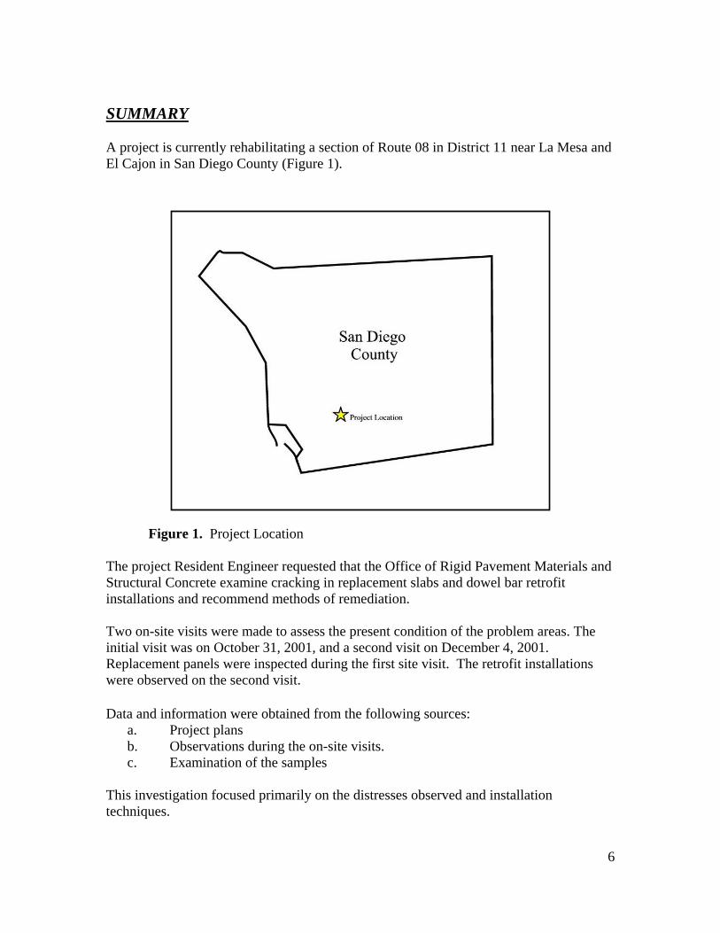
SUMMARY A project is currently rehabilitating a section of Route 08 in District 11 near La Mesa and El Cajon in San Diego County (Figure 1).
Figure 1. Project Location The project Resident Engineer requested that the Office of Rigid Pavement Materials and Structural Concrete examine cracking in replacement slabs and dowel bar retrofit installations and recommend methods of remediation. Two on-site visits were made to assess the present condition of the problem areas. The initial visit was on October 31, 2001, and a second visit on December 4, 2001. Replacement panels were inspected during the first site visit. The retrofit installations were observed on the second visit. Data and information were obtained from the following sources:
a. Project plans b. Observations during the on-site visits. c. Examination of the samples
This investigation focused primarily on the distresses observed and installation techniques.
6

As a repair for the cracked replacement panels, the district was already considering the following options:
1. Fill the cracks with high molecular weight methacrylate (HMWM) 2. Fill the cracks with injection epoxy 3. Replace the concrete slabs.
The second site visit on December 4, 2001 revealed a number of problems with the retrofit installations. For example:
1. Dowel bar slots were constructed incorrectly. 2. Foam boards were not aligned with existing transverse joints. 3. Sealant was not being applied in the transverse joint
7
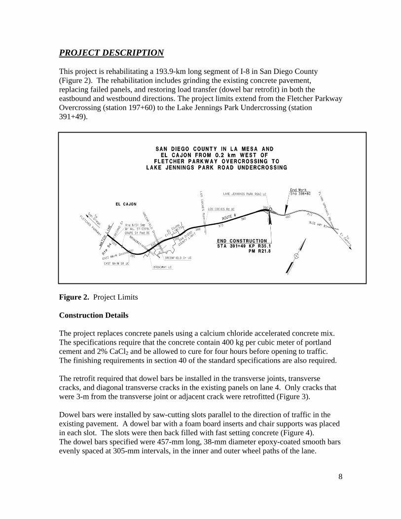
PROJECT DESCRIPTION This project is rehabilitating a 193.9-km long segment of I-8 in San Diego County (Figure 2). The rehabilitation includes grinding the existing concrete pavement, replacing failed panels, and restoring load transfer (dowel bar retrofit) in both the eastbound and westbound directions. The project limits extend from the Fletcher Parkway Overcrossing (station 197+60) to the Lake Jennings Park Undercrossing (station 391+49).
Figure 2. Project Limits Construction Details The project replaces concrete panels using a calcium chloride accelerated concrete mix. The specifications require that the concrete contain 400 kg per cubic meter of portland cement and 2% CaCl2 and be allowed to cure for four hours before opening to traffic. The finishing requirements in section 40 of the standard specifications are also required. The retrofit required that dowel bars be installed in the transverse joints, transverse cracks, and diagonal transverse cracks in the existing panels on lane 4. Only cracks that were 3-m from the transverse joint or adjacent crack were retrofitted (Figure 3). Dowel bars were installed by saw-cutting slots parallel to the direction of traffic in the existing pavement. A dowel bar with a foam board inserts and chair supports was placed in each slot. The slots were then back filled with fast setting concrete (Figure 4). The dowel bars specified were 457-mm long, 38-mm diameter epoxy-coated smooth bars evenly spaced at 305-mm intervals, in the inner and outer wheel paths of the lane.
8
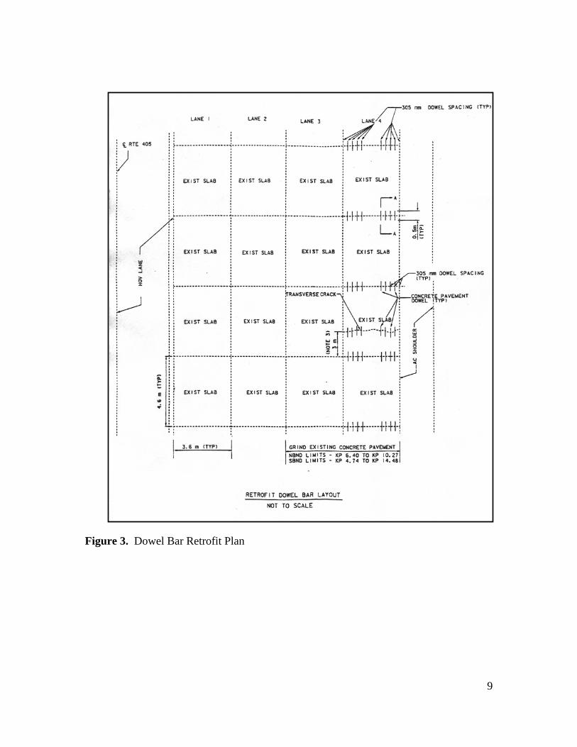
Figure 3. Dowel Bar Retrofit Plan
9
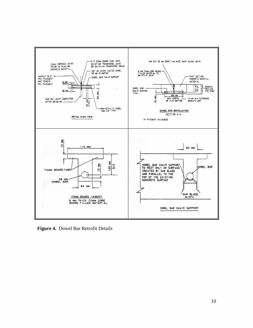
Figure 4. Dowel Bar Retrofit Details
10
INSPECTION TEAM Pavement inspections were performed by: Office of Rigid Pavement and Structural Concrete Doran Glauz Senior Materials & Research Engineer Karl Smith Maintenance Manager I Raul Alarcon Transportation Engineer District 11 - Maintenance
Bruce Lambert Branch Chief Transportation Engineer Area Superintendent
District 11 Al Ochoa Senior Transportation Engineer
Al-Jafri Resident Engineer Arthur Padilla District Materials Engineer
David Evans Pavement Engineer Bruce Lambert Project Engineer Branch Chief Sylvester Lin Pavement Management Eric Sarkela Transportation Engineer Lauren Kemp Construction / Design Headquarters
Leo Mahserelli HA22 Program Advisor
Industry
Hazard Company FIELD OBSERVATIONS
11
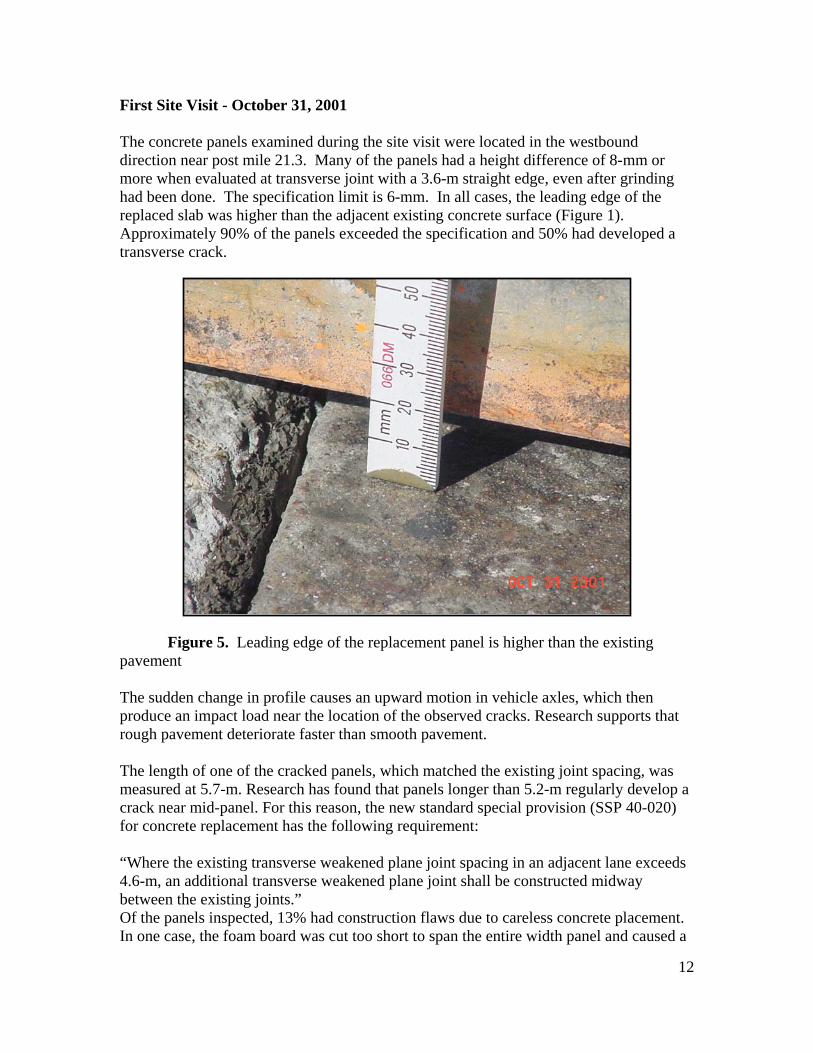
First Site Visit - October 31, 2001 The concrete panels examined during the site visit were located in the westbound direction near post mile 21.3. Many of the panels had a height difference of 8-mm or more when evaluated at transverse joint with a 3.6-m straight edge, even after grinding had been done. The specification limit is 6-mm. In all cases, the leading edge of the replaced slab was higher than the adjacent existing concrete surface (Figure 1). Approximately 90% of the panels exceeded the specification and 50% had developed a transverse crack.
Figure 5. Leading edge of the replacement panel is higher than the existing
pavement The sudden change in profile causes an upward motion in vehicle axles, which then produce an impact load near the location of the observed cracks. Research supports that rough pavement deteriorate faster than smooth pavement. The length of one of the cracked panels, which matched the existing joint spacing, was measured at 5.7-m. Research has found that panels longer than 5.2-m regularly develop a crack near mid-panel. For this reason, the new standard special provision (SSP 40-020) for concrete replacement has the following requirement: “Where the existing transverse weakened plane joint spacing in an adjacent lane exceeds 4.6-m, an additional transverse weakened plane joint shall be constructed midway between the existing joints.” Of the panels inspected, 13% had construction flaws due to careless concrete placement. In one case, the foam board was cut too short to span the entire width panel and caused a
12
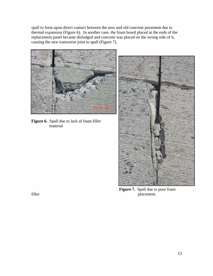
spall to form upon direct contact between the new and old concrete pavement due to thermal expansion (Figure 6). In another case, the foam board placed at the ends of the replacement panel became dislodged and concrete was placed on the wrong side of it, causing the new transverse joint to spall (Figure 7).
Figure 6. Spall due to lack of foam filler material
Figure 7. Spall due to poor foam filler placement.
13
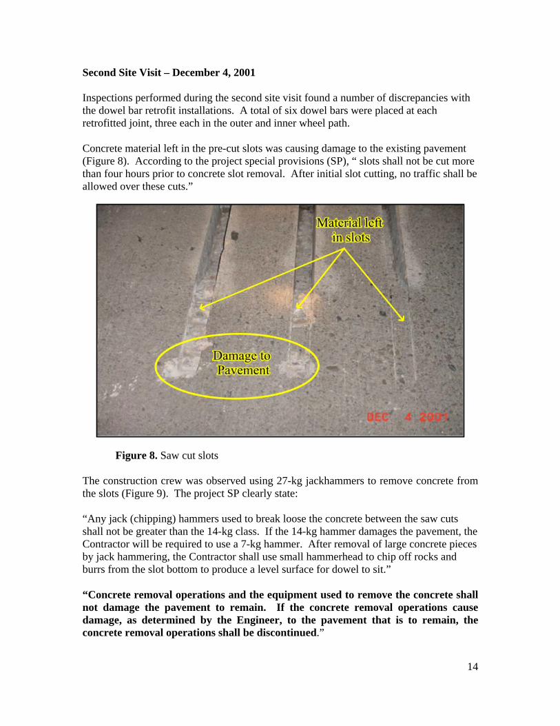
Second Site Visit – December 4, 2001 Inspections performed during the second site visit found a number of discrepancies with the dowel bar retrofit installations. A total of six dowel bars were placed at each retrofitted joint, three each in the outer and inner wheel path. Concrete material left in the pre-cut slots was causing damage to the existing pavement (Figure 8). According to the project special provisions (SP), “ slots shall not be cut more than four hours prior to concrete slot removal. After initial slot cutting, no traffic shall be allowed over these cuts.”
Figure 8. Saw cut slots
The construction crew was observed using 27-kg jackhammers to remove concrete from the slots (Figure 9). The project SP clearly state: “Any jack (chipping) hammers used to break loose the concrete between the saw cuts shall not be greater than the 14-kg class. If the 14-kg hammer damages the pavement, the Contractor will be required to use a 7-kg hammer. After removal of large concrete pieces by jack hammering, the Contractor shall use small hammerhead to chip off rocks and burrs from the slot bottom to produce a level surface for dowel to sit.” “Concrete removal operations and the equipment used to remove the concrete shall not damage the pavement to remain. If the concrete removal operations cause damage, as determined by the Engineer, to the pavement that is to remain, the concrete removal operations shall be discontinued.”
14

Figure 9. Removal of Concrete from slots
After removing the concrete, the slots were vacuumed and sandblasted to ensure any debris remaining is removed and all surfaces are clean and dry. An inspection of one of the slots revealed that moisture remained after being sandblasted (Figure 10).
Figure 10. Slot Cleaning
15
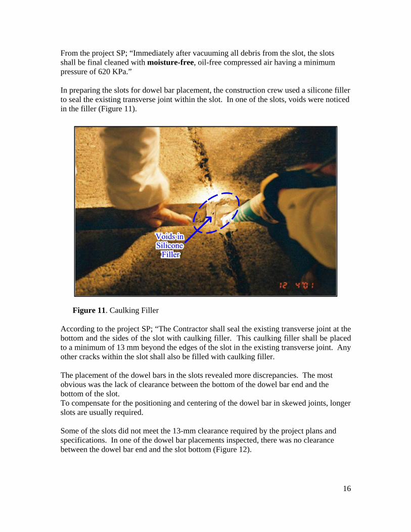
From the project SP; “Immediately after vacuuming all debris from the slot, the slots shall be final cleaned with moisture-free, oil-free compressed air having a minimum pressure of 620 KPa.” In preparing the slots for dowel bar placement, the construction crew used a silicone filler to seal the existing transverse joint within the slot. In one of the slots, voids were noticed in the filler (Figure 11).
Figure 11. Caulking Filler
According to the project SP; “The Contractor shall seal the existing transverse joint at the bottom and the sides of the slot with caulking filler. This caulking filler shall be placed to a minimum of 13 mm beyond the edges of the slot in the existing transverse joint. Any other cracks within the slot shall also be filled with caulking filler. The placement of the dowel bars in the slots revealed more discrepancies. The most obvious was the lack of clearance between the bottom of the dowel bar end and the bottom of the slot. To compensate for the positioning and centering of the dowel bar in skewed joints, longer slots are usually required. Some of the slots did not meet the 13-mm clearance required by the project plans and specifications. In one of the dowel bar placements inspected, there was no clearance between the dowel bar end and the slot bottom (Figure 12).
16

Figure 12. Dowel Clearance
From the project SP; “The (dowel bar) chair shall provide a minimum of 13-mm clearance between the bottom of the dowel bar and the bottom of the slot. The dowel bars shall be placed to the depth shown on the plans, parallel to the traffic lane centerline and the top of the roadway surface, and at the middle of the slot, all within a tolerance of 6 mm. Dowels shall be centered at the transverse joint, such that not less than 205 and not more than 255 mm of the dowel extend into each adjacent panel.” “Skewed joints may require slots longer than the length specified in the plans. No additional compensation shall be made for additional length or any component of the dowel bar retrofit beyond limits as shown on the plans.”
In a meeting with the Resident Engineer on December 6, 2001, core samples from the retrofit installations were examined. A couple cores showed that the existing pavement below the dowel bar slots had been fractured from the use of the heavier jackhammers (Figure 13).
17

Figure 13. Fractures from using heavy Jackhammers Another core sample showed that fast-setting grout was poorly consolidated around the dowel bar (Figure 14). Numerous voids were evident. The project SP for fast-setting grout includes:
“The grout shall be vibrated with a small hand held vibrator capable of thoroughly consolidating the grout material into the slot and around the dowel bars. All grout shall be placed while fresh, and before the grout has taken an initial set. The surface temperature of the areas to receive the concrete shall be 5º C or above when grout is placed. Curing Grout. – Fast setting grout shall be cured in conformance with the provisions in Section 90-7.01, of the Standard Specifications.” The ambient air temperature during the second site visit was about 7º C.
18

Figure 14. Consolidation of Grout Material
19

Form Board
Figure 15 Foam Board Misalignment
CONCLUSIONS There is no doubt that there was poor workmanship on this project. New panel replacements and dowel bar retrofit installations were not being constructed in conformance with the specifications. Panel Replacements Only a small section of the project was reviewed. In this section, the cracks in many of the panels were past the 1/3-point in the panels and before midpoint (with one exception), and 2M from the leading edge of the slab. Based on these observations in this area it's likely that all cracked slabs were longer than 4.6M and fall in the area of 5 to 5.2M. Slabs with low strength of CaCI and that length range are expected to crack over a period of time. What this means is most of the cracks should have nothing done to them. HOWEVER, the individual slabs with cracks need to be reviewed to determent what type of repair is necessary.
20
Slabs longer then 4.6M with cracks should be repaired with Epoxy and if they have additional construction distresses they need to be replaced. Other Distresses and spalls in the transverse joints are due to the lack of expansion joint filler. RECOMMENDATIONS The cooperation between the resident engineer and the paving contractor is leading to the successful completion this project. The appropriate repair strategy depends upon the number of flaws in an individual slab. Slabs longer than 4.6-m that are cracked should be considered as two slabs and treated as such. Slabs with only a transverse crack can be repaired with epoxy or HMWM. Since the cracks tend to be large (>1-mm) and a bound base may be under some of the slabs, epoxy is the preferred material. Slabs with a transverse crack and some other flaw should be considered manifestly flawed and should be replaced. Any new slab replacements should be constructed in conformance with the specifications. The elevation of the pavement surface shall be such that water will not pond on either side of the longitudinal contact joint with existing pavement.The new pavement surface at the longitudinal contact joint shall conform as closely as possible to the elevation of the existing concrete Any difference in elevation between the new pavement and the existing pavement shall be eliminated by finishing the new pavement within 0.3-m of the existing pavement by hand methods, adding or removing Concrete as necessary. Overall the projects looks very good, but please understand that any detail, no matter how small, cannot be left for field maintenance to correct because they do not have the resources or experience for this type of project.
21
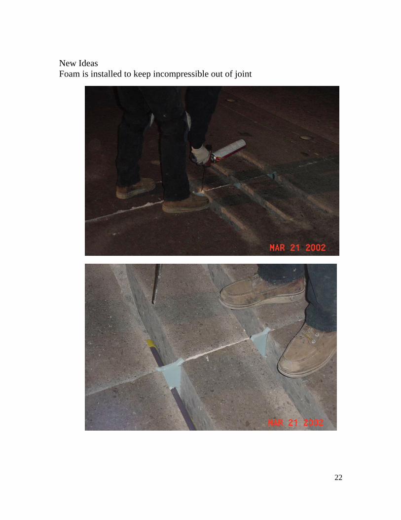
New Ideas Foam is installed to keep incompressible out of joint
22
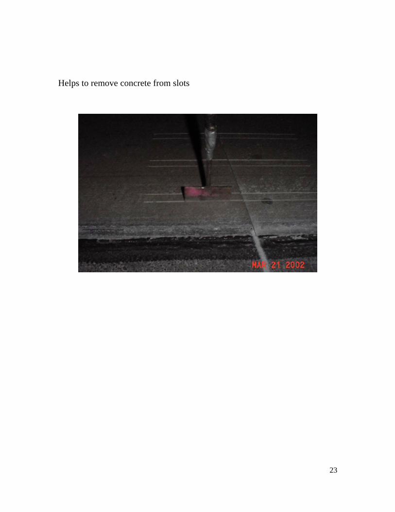
Helps to remove concrete from slots
23
24
POINTS OF CONTACT Office of Rigid Pavement and Structural Concrete Tom Pyle Office Chief (916) 227-7281 Doran Glauz Materials & Research (916) 227-7272 Karl Smith Maintenance Liaison (916) 227-7230 Raul Alarcon Consultations and Investigations (916) 227-7913 District 11
Al Ochoa Senior Transportation Engineer (619) 688-6879 Al-Jafri Resident Engineer (619) 667-3110 Arthur Padilla District Materials Engineer (858) 467-4050
David Evans Pavement Engineer (858) 467-4056 Bruce Lambert Project Engineer Branch Chief (619) 688-3313 Sylvester Lin Pavement Management (619) 688-3676 Eric Sarkela Transportation Engineer (858) 627-3987 Lauren Kemp Construction / Design (858) 688-1498 Headquarters
Leo Mahserelli HA22 Program Advisor (916) 651-2007
Industry