stanley security solutions stanley healthcare solutions division · 2017-10-18 · stanley security...
TRANSCRIPT

Stanley Security SolutionsStanley Healthcare Solutions Division1550 N. 20th Circle
Lincoln, NE 68503
USA:800-824-2996
Canada:866-559-6275
International:+1 (613) 592.6997
Web site:www.stanleyhealthcare.com
© 2004–2010 XMARK Corporation. All Rights Reserved.
980-000026-000 Rev 07. January 2010. Software release 1.5
WarrantyStanley Healthcare Solutions products are warranted against defects in materials and workmanship and shall perform in accordance with published specifications for the following periods:
• Infrastructure components (receivers, door and elevator controllers, keypads, exciters, wireless tag readers etc.) – 1 year
• Wrist and pendant pulse tags, asset and inter tags, and pull cords – 1 year
• Wrist and Securaband tags without pulse technology – 3 years.
Stanley Healthcare Solutions warranty is limited solely to the repair or replacement of the defective part or product. Stanley Healthcare Solutions reserves the right to change product specifications without notice.
Limitation of LiabilityThis Product has been designed for use to: a) assist personnel in summoning help when they are under personal duress, b) locate assets c) assist in the prevention of the loss of assets and/or d) reduce the risk of resident wandering through remote detection.The range, accuracy, function and performance of this Product may vary from the published specifications due to many factors, including, without limitation, site impairments from structural effects, metal objects in the vicinity, placement of the receiver and transmitter, interference from other electrical devices, atmospheric effects, installation, and maintenance. There may be other factors, which also affect performance of this Product.Stanley Healthcare Solutions does not guarantee that this Product will: a) detect 100% of the calls for personal assistance, b) locate all assets 100% of the time, c) prevent the loss of assets and/or d) detect 100% of resident wanderings. Stanley Healthcare Solutions does not guarantee that this Product will not return false reports of: a) calls for personal assistance, b) location of assets, c) loss of assets and/or d) false reports of resident wandering.Monthly testing and maintenance of this Product, as described in the Product documentation, is essential to verify the system is operating correctly and to ensure that the probability of detecting an alarm and/or locating the transmitter are maximized. The failure to undertake regular testing and maintenance will increase the risk of system failure and: a) failure to report personal duress calls, b) failure to locate assets, c) failure to prevent the loss of assets and/or d) failure to detect resident wandering. The failure to undertake regular testing and maintenance will increase the risk of false reports of: a) calls for personal assistance, b) location of assets, c) loss of assets and/or d) resident wandering.Stanley Healthcare Solutions hereby disclaims all warranties, express or implied, arising out of or in connection with any of its Products of the use or performance thereof, including but not limited to, where allowable by law, all other implied warranties or conditions of merchantable quality and fitness for a particular purpose and those arising by statute or otherwise in law or from a course of dealing or usage of trade.
RoamAlert User Guide iii
Stanley Healthcare Solutions's liability to you or anyone claiming through or on behalf of you with respect to any claim or loss arising out of the use or misuse of Stanley Healthcare Solutions's Product, defective products or materials, improper installation or maintenance of Stanley Healthcare Solutions's Product or products or the system in which they are incorporated, or alleged to have resulted from an act or omission of Stanley Healthcare Solutions or any person, negligent or otherwise, shall be limited to:A) the repair or replacement of defective Product or materials supplied by Stanley Healthcare Solutions during the warranty period as set out in the Product documentation; or, at the option of Stanley Healthcare Solutions,B) a refund of the purchase price of the Product supplied by Stanley Healthcare Solutions.In no event shall Stanley Healthcare Solutions be liable for general, specific, indirect, consequential, incidental, exemplary or punitive damages or any losses or expenses suffered by you or anyone else, whether or not Stanley Healthcare Solutions, or its employees, officers, agents, resellers or installers has been informed of the risk of such loss or expense and whether or not such losses or expenses were foreseeable.
UL ListingThis system is listed as an Access Control System by Underwriters Laboratories Inc., Standard for Safety.
Warnings• Do not operate other software programs at the same time as the RoamAlert system software—
do not use these or other software:
• Disk compression—do not use compressed disk drives.
• Back up programs —back up programs, including the Microsoft® Windows® back up program, warn of problems when continuing to use the system during a backup. Also, the system does not support the use of a tape drive. Exit the server or workstations software before starting a back up session.
• Turn off power management and screen savers for all computers used in the RoamAlert® system – power management can interfere with the proper operation of the RoamAlert system software.
• Cell phones, walkie talkies and other similar RF devices transmit at a considerably higher power than the tags used with the RoamAlert system. If these types of transmitters are used in close proximity they may compromise tag transmissions.
iv RoamAlert User Guide
Environmental Information – European UnionThe equipment used in this system has required the extraction and use of natural resources for its production. It may contain hazardous substances that could impact health and the environment.In order to avoid the dissemination of these substances in the environment and to diminish the pressure on the world’s natural resources, Stanley Healthcare Solutions encourages you to use the appropriate local or regional take-back systems. Those systems will reuse or recycle most of the materials of your equipment once it has reached the end of its service life.The crossed-out wheeled bin symbol invites you to use those systems.If you need more information on the collection, reuse and recycling systems, please contact your local or regional waste administration.You can also contact Stanley Healthcare Solutions for more information on the environmental performances of our products.
RoamAlert User Guide v

vi RoamAlert User Guide
Chapter 0ContentsList of Procedures ......................................................................... xi
1 – IntroductionWhat is the RoamAlert System?.........................................................................1-2Using This Guide .....................................................................................................1-2
Terms and Conventions Used..................................................................................... 1-2What’s In This Guide ....................................................................................................... 1-3
Using Windows........................................................................................................1-3
2 – RoamAlert System OverviewA Typical RoamAlert Installation .......................................................................2-2RoamAlert System Components .......................................................................2-4
Tags....................................................................................................................................... 2-4Tag Reader ......................................................................................................................... 2-5Receiver............................................................................................................................... 2-5Controller Hardware....................................................................................................... 2-6Computers ......................................................................................................................... 2-7
RoamAlert Software ...............................................................................................2-8User Security Levels ........................................................................................................ 2-8User Screen and Functions.........................................................................................2-11Supervisor Mode Screen and Panels ......................................................................2-13Administrator Mode Screen and Panels................................................................2-14
System Icons .......................................................................................................... 2-17
3 – Basic ProceduresLogging On to Wizards .........................................................................................3-2Assigning a Tag to a Resident.............................................................................3-3Attaching and Storing Tags.................................................................................3-8
Attaching Wrist Tags ...................................................................................................... 3-8Storing Tags....................................................................................................................... 3-9
RoamAlert User Guide vii
Editing Resident Information...........................................................................3-10Transporting a Resident.....................................................................................3-13Returning a Transported Tag ...........................................................................3-16Displaying the Tag Census................................................................................3-18Bypassing A Door or Elevator...........................................................................3-19Locating Tags.........................................................................................................3-22
Locating Tags in a Facility .......................................................................................... 3-22
Unassigning a Tag................................................................................................3-25Switching Modes ..................................................................................................3-27Printing Lists...........................................................................................................3-29
4 – Responding to AlarmsAbout Tag Alarms................................................................................................... 4-2Responding to Alarms .......................................................................................... 4-4
Accepting Alarms at a Workstation or Server ........................................................4-4Accepting TIF Alarms at a Mode 1 Access Keypad...............................................4-5Muting Alarm Sounds.....................................................................................................4-6Handling Low Battery Alarms......................................................................................4-6About System Alarms .....................................................................................................4-6Alarm Reminders..............................................................................................................4-6
5 – Activity LogsViewing the Activity Log...................................................................................... 5-2Annotate a Log Entry ............................................................................................ 5-4Search for Specific Log Entries........................................................................... 5-5
6 – Managing UsersViewing the User List............................................................................................. 6-2Adding a New User ................................................................................................ 6-3Editing User Properties......................................................................................... 6-6Deleting a User ........................................................................................................ 6-7
7 – Managing Tags
viii RoamAlert User Guide
Viewing the Tag List...............................................................................................7-2Adding New Tags to Inventory ..........................................................................7-4Deleting Tags from Inventory ......................................................................... 7-10Testing and Cleaning Tags ............................................................................... 7-11About Pendants.................................................................................................... 7-14Editing Tag Properties........................................................................................ 7-15
8 – RoamAlert System ConfigurationDefining and Managing Annotations..............................................................8-2Defining and Managing Tag Categories.........................................................8-6Defining and Managing Messaging Devices ............................................. 8-12Specifying Global Software Settings............................................................. 8-17Managing Alarm Sound Configurations...................................................... 8-20Managing Floor Plans and Floor Plan Icons ............................................... 8-24
Adding, Editing and Deleting Floor Plans ............................................................8-26Placing, Moving and Removing Node Icons........................................................8-30
Defining and Managing Workstations ......................................................... 8-32
9 – Configuring and Managing the RoamAlert NetworkSystem Testing.........................................................................................................9-2Performing Backups...............................................................................................9-3Shutting Down and Restarting the System...................................................9-4Configuring and Managing RS-485 Networks..............................................9-5Configuring and Managing Nodes ................................................................ 9-10Defining and Managing Links ......................................................................... 9-20
A – Managing Asset TagsAsset Tag Categories and Alarm Sounds....................................................... A-2Adding and Removing Asset Tags................................................................... A-2Assigning an Asset Tag to an Item................................................................... A-6Attaching, Removing and Storing Asset Tags ............................................. A-8Editing Asset Tag Properties .............................................................................. A-9
RoamAlert User Guide ix
Responding to Asset Tag Alarms......................................................................A-9
B – Tag Testing FormRecord of Tag Test Results .................................................................................. B-2
I – Index
x RoamAlert User Guide
Chapter 0List of ProceduresStart a Wizard...................................................................................................3-2Assign a Tag to a Resident ..............................................................................3-3Attach a Tag To A Resident .............................................................................3-8Edit a Resident’s Information..........................................................................3-10Transport a Resident ......................................................................................3-13Return a Tag Using the Wizard ......................................................................3-16Display the Tag Census .................................................................................3-18Take a Tagged Resident Through a Controlled Exit Door..............................3-20Take a Tagged Resident Into a Controlled Elevator.......................................3-21Locate Tags in a Facility.................................................................................3-22Unassign a Tag ..............................................................................................3-25Log In to Supervisor Mode .............................................................................3-27Log In to Administrator Mode .........................................................................3-28Print a List.......................................................................................................3-29Accept an Alarm at the Server or a Workstation ..............................................4-4Accept an Alarm at a Mode 1 Access Keypad .................................................4-5Mute an Alarm ..................................................................................................4-6View the Activity Log ........................................................................................5-2Annotate a Log Entry........................................................................................5-4Search the Activity Log for Specific Entries......................................................5-5View the User List.............................................................................................6-2Add a New User ...............................................................................................6-3Edit a User’s Information ..................................................................................6-6Delete a User....................................................................................................6-7View the Tag List ..............................................................................................7-2Add a Tag to Inventory Manually......................................................................7-4Add Multiple Tags at Once to Inventory ...........................................................7-7Delete a Tag from Inventory ...........................................................................7-10How to Test a Tag With the Tag Reader ........................................................7-12How to Test a Tag at a Door or Protected Exit...............................................7-12Clean Wrist Tags ............................................................................................7-13Edit the Properties of a Tag............................................................................7-15
RoamAlert User Guide xi
Unassign a Tag ............................................................................................. 7-17Assign a Tag.................................................................................................. 7-17Change the Expiry Date of a Tag .................................................................. 7-19Edit the Information and Configuration of a Tag............................................ 7-20Return a Transported Tag ............................................................................. 7-22View the Annotation List .................................................................................. 8-2Add a New Annotation..................................................................................... 8-3Edit an Annotation ........................................................................................... 8-4Delete an Annotation ....................................................................................... 8-5View the Tag Categories List........................................................................... 8-6Add a New Category ....................................................................................... 8-7Edit a Category.............................................................................................. 8-10Delete a Category.......................................................................................... 8-10View the Messaging Device List .................................................................... 8-12Add a New Messaging Device....................................................................... 8-13Edit a Messaging Device ............................................................................... 8-15Delete a Device ............................................................................................. 8-16Modify RoamAlert Software Settings............................................................. 8-17View the Alarm Sounds List........................................................................... 8-20Change a Defined Alarm Sound.................................................................... 8-21View Floor Plans............................................................................................ 8-24Add a New Floor............................................................................................ 8-26Edit a Floor Plan ............................................................................................ 8-28Delete a Floor Plan........................................................................................ 8-29Place a Node Icon on a Floor Plan................................................................ 8-30Move a Node Icon on a Floor Plan ................................................................ 8-31Remove a Node Icon from a Floor Plan ........................................................ 8-31View the Console List .................................................................................... 8-32Add a New Console....................................................................................... 8-33Edit a Console ............................................................................................... 8-37Delete a Console ........................................................................................... 8-38Perform a Manual Backup ............................................................................... 9-3Shut Down the RoamAlert Server or a Workstation ........................................ 9-4Restart the RoamAlert Server or a Workstation .............................................. 9-4View the RS-485 Network Panel ..................................................................... 9-5Add an RS-485 Network.................................................................................. 9-6
xii RoamAlert User Guide
Edit the Baud Rate of an RS-485 Network .......................................................9-8Delete an RS-485 Network...............................................................................9-8View the Nodes Panel ....................................................................................9-10Add a Node.....................................................................................................9-11Edit A Node’s Properties ................................................................................9-17Delete a Node.................................................................................................9-19View the Links List..........................................................................................9-20Add A New Link ..............................................................................................9-21Edit a Link’s Properties...................................................................................9-25Delete a Link...................................................................................................9-26Add an Asset Tag to Inventory ........................................................................ A-2Delete an Asset Tag from Inventory ................................................................ A-5Assign an Asset Tag to an Item....................................................................... A-6Attach an Asset Tag to an Item ....................................................................... A-8Remove an Asset Tag from an Item................................................................ A-8Clean and Store an Asset Tag ........................................................................ A-8
RoamAlert User Guide xiii

xiv RoamAlert User Guide
Chapter 1CHAPTER 0INTRODUCTION
Welcome to the RoamAlert® resident safety system, and thank you for choosing a Stanley Healthcare Solutions product. This document is your guide to using the RoamAlert system and software. It is intended for facility staff who are responsible for using, administering and maintaining the system. Although this document contains sections on configuring devices and software settings, the general assumption is that your system has been installed, configured and commissioned by your Authorized RoamAlert Dealer.
RoamAlert User Guide 1–1
What is the RoamAlert System?
What is the RoamAlert System?The RoamAlert system is designed to create, in conjunction with staff diligence, a secure perimeter that helps deter residents and assets from leaving the protected area of a facility. Residents and assets are tagged with a Stanley Healthcare Solutions transponder (or Tag) that generates an alarm when the tag approaches a protected exit. Also available are fixed-location pull cords for resident duress applications and inter tags that interconnect with the Stanley Healthcare Solutions TABS® fall management system.RoamAlert implements a three-level password-protected security access level system for user interaction with the software. Your RoamAlert administrator should have provided you with a password and security level.
Using This Guide
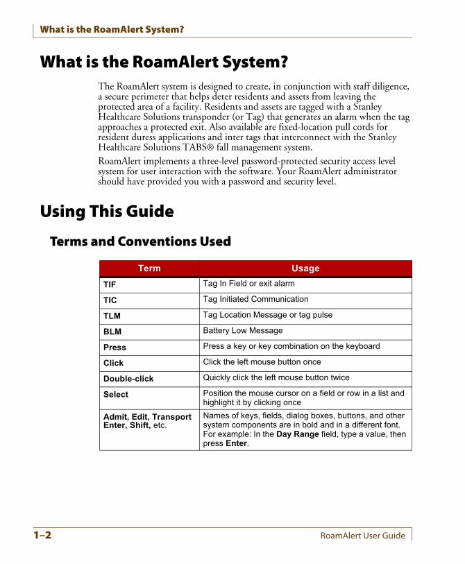
Terms and Conventions Used
Term Usage
TIF Tag In Field or exit alarm
TIC Tag Initiated Communication
TLM Tag Location Message or tag pulse
BLM Battery Low Message
Press Press a key or key combination on the keyboard
Click Click the left mouse button once
Double-click Quickly click the left mouse button twice
Select Position the mouse cursor on a field or row in a list and highlight it by clicking once
Admit, Edit, Transport Enter, Shift, etc.
Names of keys, fields, dialog boxes, buttons, and other system components are in bold and in a different font. For example: In the Day Range field, type a value, then press Enter.
1–2 RoamAlert User Guide
Using Windows
What’s In This GuideThis guide includes an overview of the system and detailed instructions for the procedures that are used daily while working with the system.Also included are detailed discussions of tag management, configuration options and system maintenance tasks. The software functions available to you are defined by your access level: User, Supervisor or Administrator.
For the UserIf you are a user, you should read the “RoamAlert System Overview” chapter to become familiar with the system, the “Basic Procedures” chapter to learn about the tasks you perform on a daily basis, and the “Responding to Alarms” chapter to learn about dealing with warnings and alarms.Procedures to transport tags, however, can only be performed by staff with Supervisor or Administrator access.
For the SupervisorIf you are a Supervisor, you can perform all the procedures available to the User. Therefore, you should become familiar with the same material. Since you have access to several other RoamAlert functions, you should read the chapters “Activity Logs”, “Managing Tags” and “Managing Users”. As well, in the chapter “RoamAlert System Configuration”, you should read the sections “Defining and Managing Annotations”, “Defining and Managing Tag Categories” and, if your facility uses RoamAlert messaging functions, “Defining and Managing Messaging Devices”.
For the AdministratorIf you are an Administrator, you can perform all procedures available to the User and Supervisor, and you should be familiar with all aspects of the RoamAlert system. Chapters in this guide specific to administrative tasks include “RoamAlert System Configuration” and “Configuring and Managing the RoamAlert Network”.
Using WindowsThis guide assumes that you are familiar with, and capable of using, the Microsoft Windows XP operating system. If you are new to Windows or require a refresher on its features, please refer to the many available sources including the Windows manuals and online tutorials.
RoamAlert User Guide 1–3

Using Windows
1–4 RoamAlert User Guide
Chapter 2CHAPTER 0ROAMALERT SYSTEM
OVERVIEW
The RoamAlert resident safety system is a hardware and software system designed to deter residents and assets from leaving a department or facility. The system can also be used to locate residents and provide emergency call functions within the RoamAlert perimeter.This chapter describes:
• A typical RoamAlert installation
• The individual components of the system such as tags, controllers, receivers and computers
• User security levels
• The software interface
RoamAlert User Guide 2–1
A Typical RoamAlert Installation
A Typical RoamAlert Installation
2–2 RoamAlert User Guide
A Typical RoamAlert Installation
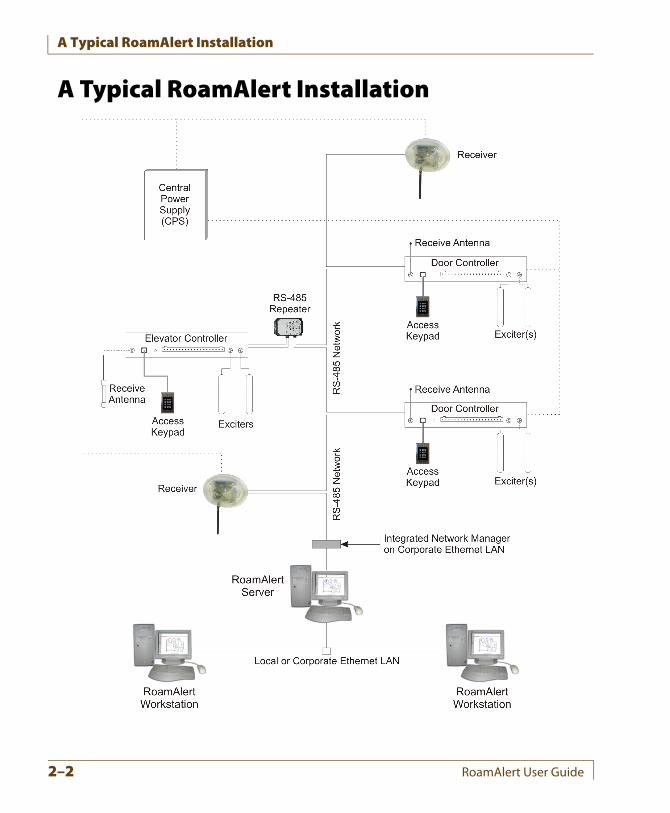
In a typical RoamAlert resident safety system installation, a section of a facility is defined as a “safe (or protected) area.” Residents may move around freely within this area. Exits from the safe area are equipped with exciters mounted beside the exit doors. As a resident approaches a protected door, the exciter’s RF (radio frequency) field causes the resident’s tag to send a special identifying signal to the exciter’s controller. The controller passes this information over the network to the RoamAlert server, which automatically displays a warning or an alarm and optionally, locks the door, or activates a CCTV or paging system, among other possible functions.Keypads are installed at exit points so that staff members can bypass the door controller and transport a resident outside the safe area without triggering an alarm.If your facility is large, one or more workstations (called consoles in the software) may also be installed. As the server receives alarms, it directs them to the closest workstations, which then display the alarm. At a workstation, an alarm can be accepted, and resident tags can be assigned, transported and unassigned.Wrist tags are worn by residents. These are available with or without Tag Pulse technology. A pulse tag, which is green, emits an identifying signal (pulse) every 16 seconds. Receivers located throughout the safe area pick up these pulses and transmit the information to the RoamAlert server. If the server does not receive these pulses, a warning or alarm can be displayed.Residents can be authorized to leave the safe area for testing and other legitimate purposes. This is accomplished by completing a software procedure that “transports” the tag out of the area for a specified length of time. If the tag is not detected by the system after the transport time has expired, an alarm can be automatically generated.The RoamAlert system employs a network based on the RS-485 protocol. All devices in the system are connected through this network and they are continually supervised by the server software. Alarms are automatically generated if communication with any RoamAlert device is lost or compromised.If the safe area of your facility occupies more than one floor, special controllers and repeaters are used to monitor elevators. In a large facility, repeaters are also used to extend the coverage area.Typically, the RoamAlert system will have its own central power supply with battery backup, so that the system will continue to operate without interruption in the event of power problems.
RoamAlert User Guide 2–3
RoamAlert System Components
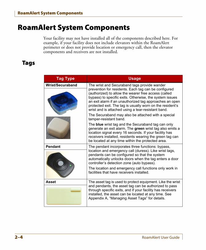
RoamAlert System ComponentsYour facility may not have installed all of the components described here. For example, if your facility does not include elevators within the RoamAlert perimeter or does not provide location or emergency call, then the elevator components and receivers are not installed.
Tags
Tag Type Usage
Wrist/Securaband The wrist and Securaband tags provide wander prevention for residents. Each tag can be configured (authorized) to allow the wearer free access (called bypass) to specific exits. Otherwise, the system issues an exit alarm if an unauthorized tag approaches an open protected exit. The tag is usually worn on the resident’s wrist and is attached using a tear-resistant band.
The Securaband may also be attached with a special tamper-resistant band.
The blue wrist tag and the Securaband tag can only generate an exit alarm. The green wrist tag also emits a location signal every 16 seconds. If your facility has receivers installed, residents wearing the green tag can be located at any time within the protected area.
Pendant The pendant incorporates three functions: bypass, location and emergency call (duress). Like wrist tags, pendants can be configured so that the system automatically unlocks doors when the tag enters a door controller’s detection zone (auto bypass).
The location and emergency call functions only work in facilities that have receivers installed.
Asset The asset tag is used to protect equipment. Like the wrist and pendants, the asset tag can be authorized to pass through specific exits, and if your facility has receivers installed, the asset can be located at any time. See Appendix A, “Managing Asset Tags” for details.
2–4 RoamAlert User Guide
RoamAlert System Components
Tag Reader
Receiver
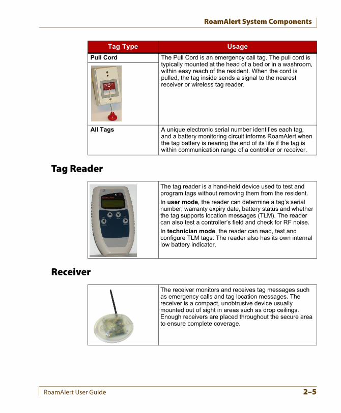
Pull Cord The Pull Cord is an emergency call tag. The pull cord is typically mounted at the head of a bed or in a washroom, within easy reach of the resident. When the cord is pulled, the tag inside sends a signal to the nearest receiver or wireless tag reader.
All Tags A unique electronic serial number identifies each tag, and a battery monitoring circuit informs RoamAlert when the tag battery is nearing the end of its life if the tag is within communication range of a controller or receiver.
Tag Type Usage
The tag reader is a hand-held device used to test and program tags without removing them from the resident.
In user mode, the reader can determine a tag’s serial number, warranty expiry date, battery status and whether the tag supports location messages (TLM). The reader can also test a controller’s field and check for RF noise.
In technician mode, the reader can read, test and configure TLM tags. The reader also has its own internal low battery indicator.
The receiver monitors and receives tag messages such as emergency calls and tag location messages. The receiver is a compact, unobtrusive device usually mounted out of sight in areas such as drop ceilings. Enough receivers are placed throughout the secure area to ensure complete coverage.
RoamAlert User Guide 2–5
RoamAlert System Components
Controller Hardware
Item Usage
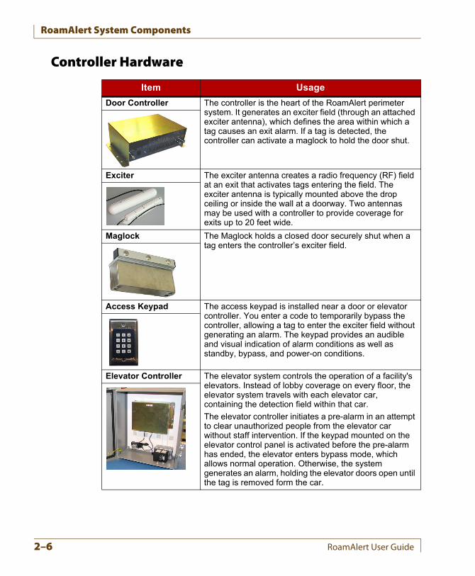
Door Controller The controller is the heart of the RoamAlert perimeter system. It generates an exciter field (through an attached exciter antenna), which defines the area within which a tag causes an exit alarm. If a tag is detected, the controller can activate a maglock to hold the door shut.
Exciter The exciter antenna creates a radio frequency (RF) field at an exit that activates tags entering the field. The exciter antenna is typically mounted above the drop ceiling or inside the wall at a doorway. Two antennas may be used with a controller to provide coverage for exits up to 20 feet wide.
Maglock The Maglock holds a closed door securely shut when a tag enters the controller’s exciter field.
Access Keypad The access keypad is installed near a door or elevator controller. You enter a code to temporarily bypass the controller, allowing a tag to enter the exciter field without generating an alarm. The keypad provides an audible and visual indication of alarm conditions as well as standby, bypass, and power-on conditions.
Elevator Controller The elevator system controls the operation of a facility's elevators. Instead of lobby coverage on every floor, the elevator system travels with each elevator car, containing the detection field within that car.
The elevator controller initiates a pre-alarm in an attempt to clear unauthorized people from the elevator car without staff intervention. If the keypad mounted on the elevator control panel is activated before the pre-alarm has ended, the elevator enters bypass mode, which allows normal operation. Otherwise, the system generates an alarm, holding the elevator doors open until the tag is removed form the car.
2–6 RoamAlert User Guide
RoamAlert System Components
Computers
RoamAlert Server and Workstations
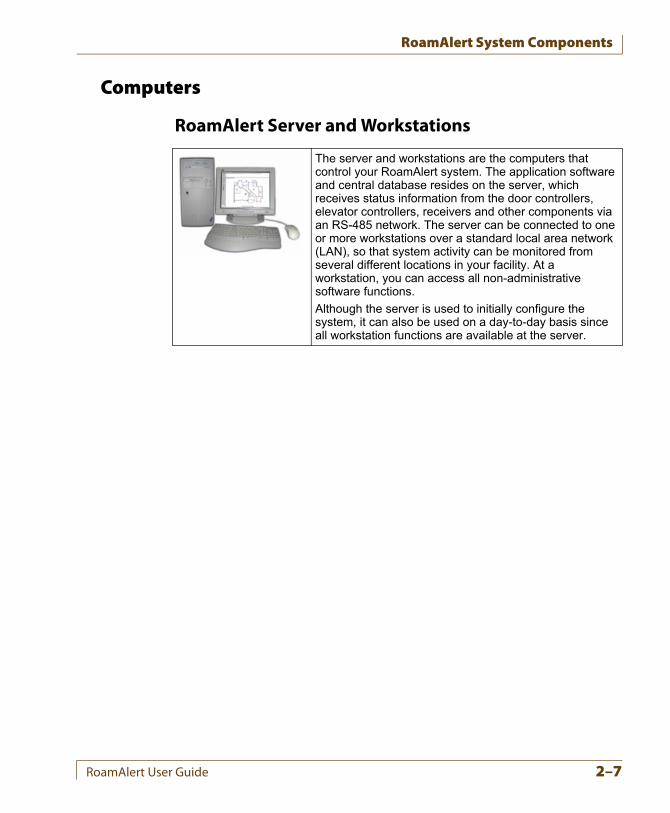
The server and workstations are the computers that control your RoamAlert system. The application software and central database resides on the server, which receives status information from the door controllers, elevator controllers, receivers and other components via an RS-485 network. The server can be connected to one or more workstations over a standard local area network (LAN), so that system activity can be monitored from several different locations in your facility. At a workstation, you can access all non-administrative software functions.
Although the server is used to initially configure the system, it can also be used on a day-to-day basis since all workstation functions are available at the server.
RoamAlert User Guide 2–7
RoamAlert Software
RoamAlert SoftwareRoamAlert is an event-driven system. That is, the RoamAlert software responds to user and system events as they occur.A user event occurs when you click a button on the interface, or press a specific key combination, to perform a function. For example, to assign a tag to a resident, you click the Assign button at a RoamAlert workstation. The Assign Tag Wizard starts and guides you through the procedure.A system event occurs when RoamAlert responds to activity within the protected perimeter of your facility, or an event is triggered by a setting. For example:
• When a tag approaches a controlled door, the tag emits a unique Tag In Field (TIF) message. This message is received by the controller, and if the tag is not authorized to be at that door, the RoamAlert software generates a warning if the door is closed or an alarm if the door is open, and displays these on any workstation configured to receive alarms from that controller.
• In a receiver-based system, when the button is pressed on the pendant or the cord is pulled on the pull cord unit or an asset tag is removed from an item, the tag emits a Tag Initiated Communication (TIC) message.
User Security LevelsThe RoamAlert software functions are organized by security level. Each function has an associated user security level. The three user levels are:
• User
• Supervisor
• Administrator
Each type of user can access specific RoamAlert functions as described in the following table:
2–8 RoamAlert User Guide
RoamAlert Software
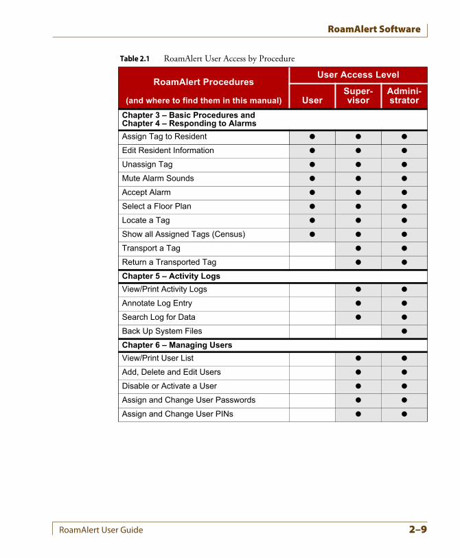
Table 2.1 RoamAlert User Access by Procedure
RoamAlert Procedures
(and where to find them in this manual)
User Access Level
UserSuper-visor
Admini-strator
Chapter 3 – Basic Procedures and Chapter 4 – Responding to Alarms
Assign Tag to Resident
Edit Resident Information
Unassign Tag
Mute Alarm Sounds
Accept Alarm
Select a Floor Plan
Locate a Tag
Show all Assigned Tags (Census)
Transport a Tag
Return a Transported Tag
Chapter 5 – Activity Logs
View/Print Activity Logs
Annotate Log Entry
Search Log for Data
Back Up System Files
Chapter 6 – Managing Users
View/Print User List
Add, Delete and Edit Users
Disable or Activate a User
Assign and Change User Passwords
Assign and Change User PINs
RoamAlert User Guide 2–9
RoamAlert Software
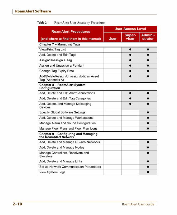
Chapter 7 – Managing Tags
View/Print Tag List
Add, Delete and Edit Tags
Assign/Unassign a Tag
Assign and Unassign a Pendant
Change Tag Expiry Date
Add/Delete/Assign/Unassign/Edit an Asset Tag (Appendix A)
Chapter 8 – RoamAlert System Configuration
Add, Delete and Edit Alarm Annotations
Add, Delete and Edit Tag Categories
Add, Delete, and Manage Messaging Devices
Specify Global Software Settings
Add, Delete and Manage Workstations
Manage Alarm and Sound Configuration
Manage Floor Plans and Floor Plan Icons
Chapter 9 – Configuring and Managing the RoamAlert Network
Add, Delete and Manage RS-485 Networks
Add, Delete and Manage Nodes
Manage Controllers, Receivers and Elevators
Add, Delete and Manage Links
Set up Network Communication Parameters
View System Logs
Table 2.1 RoamAlert User Access by Procedure
RoamAlert Procedures
(and where to find them in this manual)
User Access Level
UserSuper-visor
Admini-strator
2–10 RoamAlert User Guide
RoamAlert Software
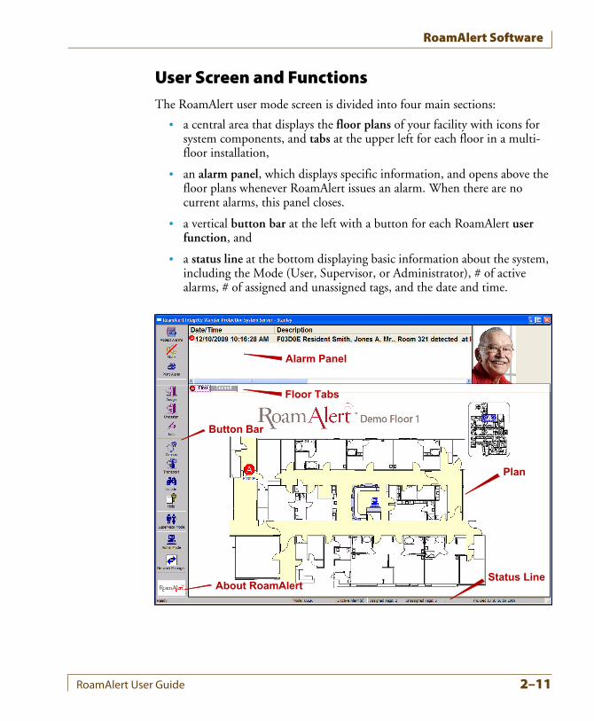
User Screen and FunctionsThe RoamAlert user mode screen is divided into four main sections:
• a central area that displays the floor plans of your facility with icons for system components, and tabs at the upper left for each floor in a multi-floor installation,
• an alarm panel, which displays specific information, and opens above the floor plans whenever RoamAlert issues an alarm. When there are no current alarms, this panel closes.
• a vertical button bar at the left with a button for each RoamAlert user function, and
• a status line at the bottom displaying basic information about the system, including the Mode (User, Supervisor, or Administrator), # of active alarms, # of assigned and unassigned tags, and the date and time.
Plan
Floor Tabs
Button Bar
Status Line
Alarm Panel
About RoamAlert
RoamAlert User Guide 2–11
RoamAlert Software
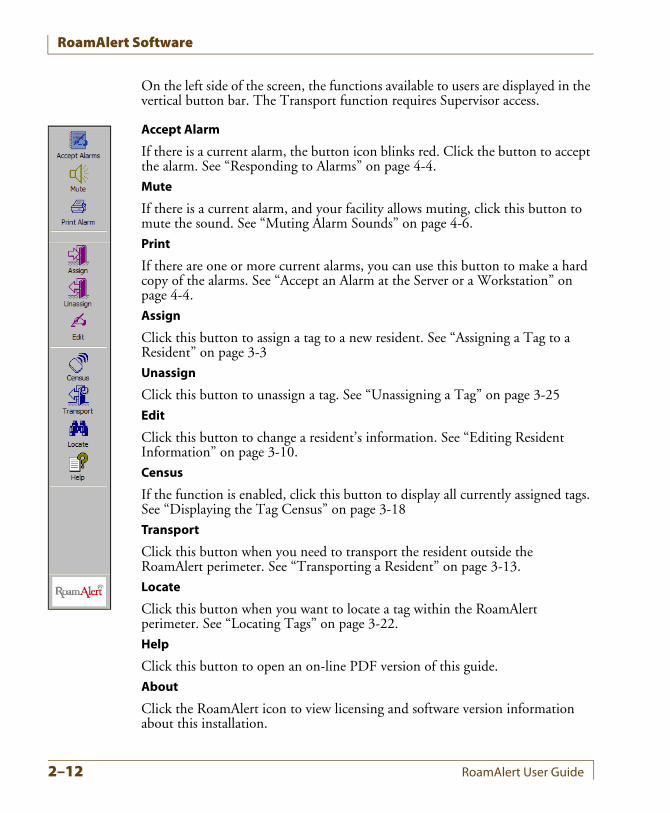
On the left side of the screen, the functions available to users are displayed in the vertical button bar. The Transport function requires Supervisor access.
Accept Alarm
If there is a current alarm, the button icon blinks red. Click the button to accept the alarm. See “Responding to Alarms” on page 4-4.Mute
If there is a current alarm, and your facility allows muting, click this button to mute the sound. See “Muting Alarm Sounds” on page 4-6.Print
If there are one or more current alarms, you can use this button to make a hard copy of the alarms. See “Accept an Alarm at the Server or a Workstation” on page 4-4.Assign
Click this button to assign a tag to a new resident. See “Assigning a Tag to a Resident” on page 3-3Unassign
Click this button to unassign a tag. See “Unassigning a Tag” on page 3-25Edit
Click this button to change a resident’s information. See “Editing Resident Information” on page 3-10.Census
If the function is enabled, click this button to display all currently assigned tags. See “Displaying the Tag Census” on page 3-18Transport
Click this button when you need to transport the resident outside the RoamAlert perimeter. See “Transporting a Resident” on page 3-13.Locate
Click this button when you want to locate a tag within the RoamAlert perimeter. See “Locating Tags” on page 3-22.Help
Click this button to open an on-line PDF version of this guide.About
Click the RoamAlert icon to view licensing and software version information about this installation.
2–12 RoamAlert User Guide
RoamAlert Software
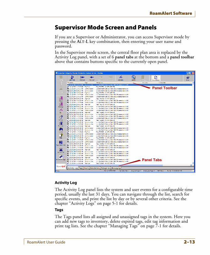
Supervisor Mode Screen and PanelsIf you are a Supervisor or Administrator, you can access Supervisor mode by pressing the ALT-L key combination, then entering your user name and password.In the Supervisor mode screen, the central floor plan area is replaced by the Activity Log panel, with a set of 6 panel tabs at the bottom and a panel toolbar above that contains buttons specific to the currently open panel.
Activity Log
The Activity Log panel lists the system and user events for a configurable time period, usually the last 31 days. You can navigate through the list, search for specific events, and print the list by day or by several other criteria. See the chapter “Activity Logs” on page 5-1 for details.Tags
The Tags panel lists all assigned and unassigned tags in the system. Here you can add new tags to inventory, delete expired tags, edit tag information and print tag lists. See the chapter “Managing Tags” on page 7-1 for details.
Panel Tabs
Panel Toolbar
RoamAlert User Guide 2–13
RoamAlert Software
Users
The Users panel lists all RoamAlert users. As a Supervisor, you can add, edit and delete users in the User, and Supervisor access groups. You can only view the properties of Administrators. See the chapter “Managing Users” on page 6-1 for details.Annotations
The Annotations panel lists the annotations that are available as notes when accepting an alarm. See “Defining and Managing Annotations” on page 8-2 in the “RoamAlert System Configuration” chapter for details.Categories
The Categories panel lists the access categories that are available to which tags are associated. See “Defining and Managing Tag Categories” on page 8-6 in the “RoamAlert System Configuration” chapter for details. Tag category functionality is supported only by controllers that have firmware version 1.4 or newer installed.Messaging
The Messaging panel lists the messaging devices, such as pagers or wireless handsets, that are configured to receive alarm notifications. You can add, edit, and delete devices from this panel. See “Defining and Managing Messaging Devices” on page 8-12 in the “RoamAlert System Configuration” chapter.
Administrator Mode Screen and PanelsIf you are an Administrator, you can access Administrator mode by pressing the ALT-D key combination, then entering your user name and password.
Note: Administrator mode is available only at the RoamAlert server. As well, all communications to workstations are suspended while the server is in this mode.
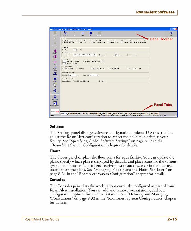
In the Administrator mode screen, the central floor plan area is replaced by the Settings panel, with a set of 13 panel tabs at the bottom and a panel toolbar above that contains buttons specific to the currently open panel.The Activity Log, Tags, Users, Annotations, Categories, and Messaging panels are the same panels available in Supervisor mode. For basic information about those panels, see the section “Supervisor Mode Screen and Panels” on page 2-13. The other seven panels are available only to Administrators at the server.
2–14 RoamAlert User Guide
RoamAlert Software
Settings
The Settings panel displays software configuration options. Use this panel to adjust the RoamAlert configuration to reflect the policies in effect at your facility. See “Specifying Global Software Settings” on page 8-17 in the “RoamAlert System Configuration” chapter for details.Floors
The Floors panel displays the floor plans for your facility. You can update the plans, specify which plan is displayed by default, and place icons for the various system components (controllers, receivers, workstations, etc.) in their correct locations on the plans. See “Managing Floor Plans and Floor Plan Icons” on page 8-24 in the “RoamAlert System Configuration” chapter for details.Consoles
The Consoles panel lists the workstations currently configured as part of your RoamAlert installation. You can add and remove workstations, and edit configuration options for each workstation. See “Defining and Managing Workstations” on page 8-32 in the “RoamAlert System Configuration” chapter for details.
Panel Tabs
Panel Toolbar
RoamAlert User Guide 2–15
RoamAlert Software
Nodes
The Nodes panel lists all nodes (controllers, receivers, I/O modules, etc.) connected to the RoamAlert network. You can add and remove nodes, and specify configuration options for each node. See“Configuring and Managing Nodes” on page 9-10 in the “Configuring and Managing the RoamAlert Network” chapter for details.Links
The Links panel lists the links currently configured for your installation. A Link is an association between the occurrence of a predefined condition (link trigger) and an operation (link action) that RoamAlert carries out in response to the trigger. See “Defining and Managing Links” on page 9-20 in the “Configuring and Managing the RoamAlert Network” chapter for details on setting up links.RS-485 Network
The RS-485 Network panel lists the individual networks that make up the RoamAlert installation. See “Configuring and Managing RS-485 Networks” on page 9-5 in the “Configuring and Managing the RoamAlert Network” chapter for details.Sounds
The Sounds panel lists the sounds specified for each tag type. You can configure RoamAlert to issue a different alarm sound for each tag type. See “Managing Alarm Sound Configurations” on page 8-20 in the “RoamAlert System Configuration” chapter for details.
2–16 RoamAlert User Guide
System Icons
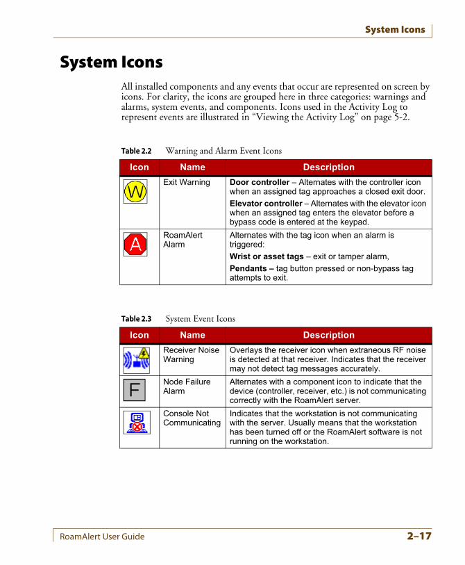
System IconsAll installed components and any events that occur are represented on screen by icons. For clarity, the icons are grouped here in three categories: warnings and alarms, system events, and components. Icons used in the Activity Log to represent events are illustrated in “Viewing the Activity Log” on page 5-2.
Table 2.2 Warning and Alarm Event Icons
Icon Name Description
Exit Warning Door controller – Alternates with the controller icon when an assigned tag approaches a closed exit door.
Elevator controller – Alternates with the elevator icon when an assigned tag enters the elevator before a bypass code is entered at the keypad.
RoamAlert Alarm
Alternates with the tag icon when an alarm is triggered:
Wrist or asset tags – exit or tamper alarm,
Pendants – tag button pressed or non-bypass tag attempts to exit.
Table 2.3 System Event Icons
Icon Name Description
Receiver Noise Warning
Overlays the receiver icon when extraneous RF noise is detected at that receiver. Indicates that the receiver may not detect tag messages accurately.
Node Failure Alarm
Alternates with a component icon to indicate that the device (controller, receiver, etc.) is not communicating correctly with the RoamAlert server.
Console Not Communicating
Indicates that the workstation is not communicating with the server. Usually means that the workstation has been turned off or the RoamAlert software is not running on the workstation.
RoamAlert User Guide 2–17
System Icons
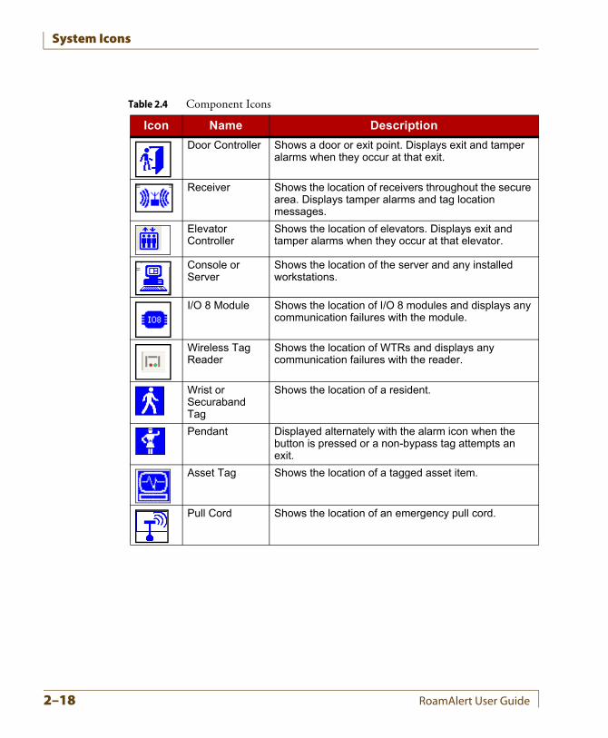
Table 2.4 Component Icons
Icon Name Description
Door Controller Shows a door or exit point. Displays exit and tamper alarms when they occur at that exit.
Receiver Shows the location of receivers throughout the secure area. Displays tamper alarms and tag location messages.
Elevator Controller
Shows the location of elevators. Displays exit and tamper alarms when they occur at that elevator.
Console or Server
Shows the location of the server and any installed workstations.
I/O 8 Module Shows the location of I/O 8 modules and displays any communication failures with the module.
Wireless Tag Reader
Shows the location of WTRs and displays any communication failures with the reader.
Wrist or Securaband Tag
Shows the location of a resident.
Pendant Displayed alternately with the alarm icon when the button is pressed or a non-bypass tag attempts an exit.
Asset Tag Shows the location of a tagged asset item.
Pull Cord Shows the location of an emergency pull cord.
2–18 RoamAlert User Guide
Chapter 3CHAPTER 0BASIC PROCEDURES
RoamAlert basic procedures include:
• Logging on to wizards
• Assigning tags to residents
• Attaching and storing tags
• Editing resident information
• Transporting a resident out of the RoamAlert perimeter
• Returning a transported resident
• Displaying the tag census
• Using the access keypad
• Locating tags
• Unassigning tags
• Switching modes and printing lists
Each facility will devise its own policies for these actions, and will identify the users who are responsible for carrying out the procedures.The descriptions in this chapter illustrate how the RoamAlert software and components are used to carry out these procedures.
RoamAlert User Guide 3–1
Logging On to Wizards
Logging On to WizardsNormally, RoamAlert should always be running on the workstations and server. If this is not the case, see “Shutting Down and Restarting the System” on page 9-4 or contact the RoamAlert administrator.Each time you start a user-mode wizard, you must first provide your user name and password to the system for authentication.
Procedure: Start a Wizard
Note: This procedure uses the Assign Tag Wizard as the example; all user-mode wizards are started in the same way.
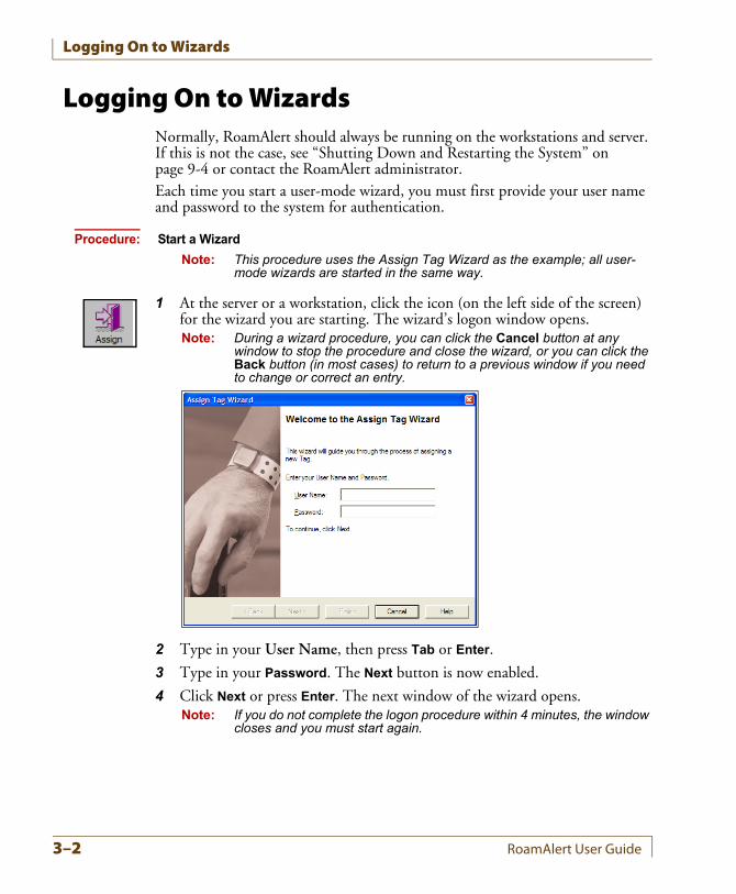
1 At the server or a workstation, click the icon (on the left side of the screen) for the wizard you are starting. The wizard’s logon window opens.Note: During a wizard procedure, you can click the Cancel button at any
window to stop the procedure and close the wizard, or you can click the Back button (in most cases) to return to a previous window if you need to change or correct an entry.
2 Type in your User Name, then press Tab or Enter.
3 Type in your Password. The Next button is now enabled.
4 Click Next or press Enter. The next window of the wizard opens.Note: If you do not complete the logon procedure within 4 minutes, the window
closes and you must start again.
3–2 RoamAlert User Guide
Assigning a Tag to a Resident
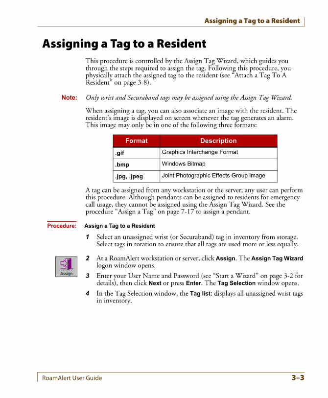
Assigning a Tag to a ResidentThis procedure is controlled by the Assign Tag Wizard, which guides you through the steps required to assign the tag. Following this procedure, you physically attach the assigned tag to the resident (see “Attach a Tag To A Resident” on page 3-8).
Note: Only wrist and Securaband tags may be assigned using the Assign Tag Wizard.
When assigning a tag, you can also associate an image with the resident. The resident’s image is displayed on screen whenever the tag generates an alarm. This image may only be in one of the following three formats:
A tag can be assigned from any workstation or the server; any user can perform this procedure. Although pendants can be assigned to residents for emergency call usage, they cannot be assigned using the Assign Tag Wizard. See the procedure “Assign a Tag” on page 7-17 to assign a pendant.
Procedure: Assign a Tag to a Resident
1 Select an unassigned wrist (or Securaband) tag in inventory from storage. Select tags in rotation to ensure that all tags are used more or less equally.
2 At a RoamAlert workstation or server, click Assign. The Assign Tag Wizard logon window opens.
3 Enter your User Name and Password (see “Start a Wizard” on page 3-2 for details), then click Next or press Enter. The Tag Selection window opens.
4 In the Tag Selection window, the Tag list: displays all unassigned wrist tags in inventory.
Format Description
.gif Graphics Interchange Format
.bmp Windows Bitmap
.jpg, .jpeg Joint Photographic Effects Group image
RoamAlert User Guide 3–3
Assigning a Tag to a Resident
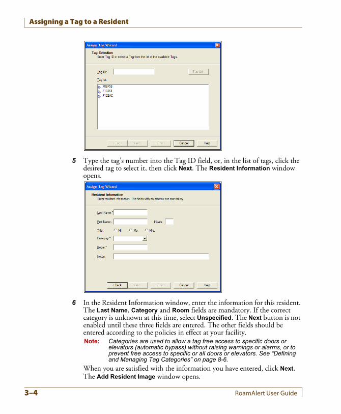
5 Type the tag’s number into the Tag ID field, or, in the list of tags, click the desired tag to select it, then click Next. The Resident Information window opens.
6 In the Resident Information window, enter the information for this resident. The Last Name, Category and Room fields are mandatory. If the correct category is unknown at this time, select Unspecified. The Next button is not enabled until these three fields are entered. The other fields should be entered according to the policies in effect at your facility.Note: Categories are used to allow a tag free access to specific doors or
elevators (automatic bypass) without raising warnings or alarms, or to prevent free access to specific or all doors or elevators. See “Defining and Managing Tag Categories” on page 8-6.
When you are satisfied with the information you have entered, click Next. The Add Resident Image window opens.
3–4 RoamAlert User Guide
Assigning a Tag to a Resident
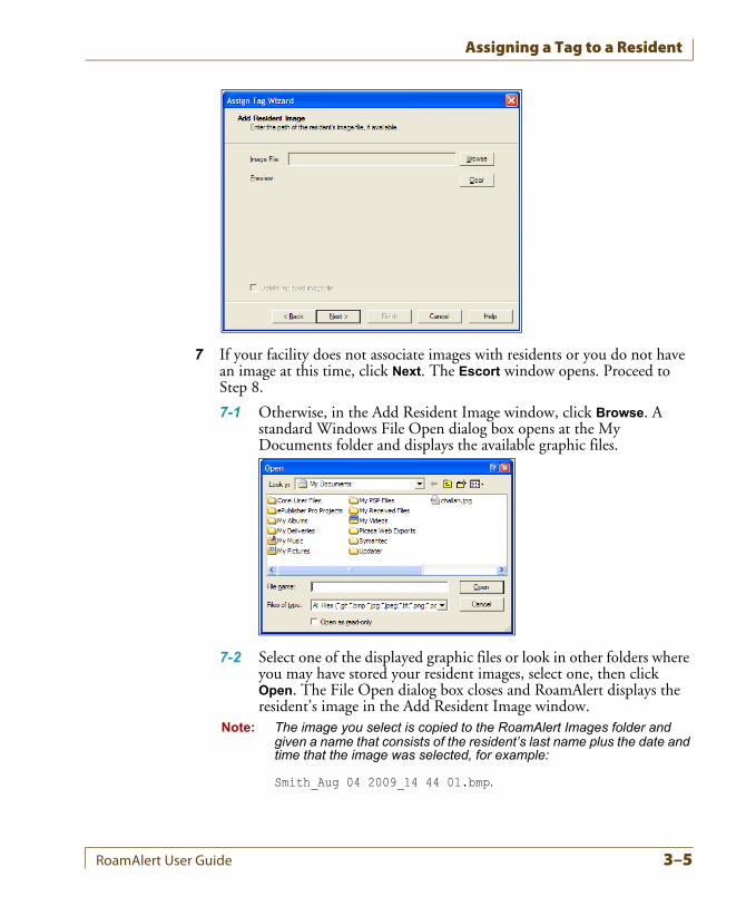
7 If your facility does not associate images with residents or you do not have an image at this time, click Next. The Escort window opens. Proceed to Step 8.
7-1 Otherwise, in the Add Resident Image window, click Browse. A standard Windows File Open dialog box opens at the My Documents folder and displays the available graphic files.
7-2 Select one of the displayed graphic files or look in other folders where you may have stored your resident images, select one, then click Open. The File Open dialog box closes and RoamAlert displays the resident’s image in the Add Resident Image window.
Note: The image you select is copied to the RoamAlert Images folder and given a name that consists of the resident’s last name plus the date and time that the image was selected, for example:
Smith_Aug 04 2009_14 44 01.bmp.
RoamAlert User Guide 3–5
Assigning a Tag to a Resident
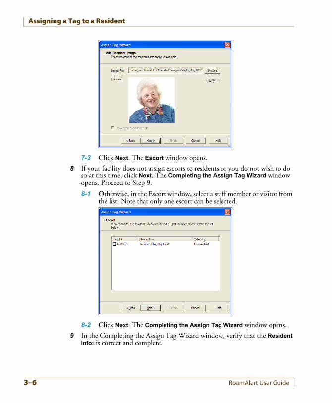
7-3 Click Next. The Escort window opens.
8 If your facility does not assign escorts to residents or you do not wish to do so at this time, click Next. The Completing the Assign Tag Wizard window opens. Proceed to Step 9.
8-1 Otherwise, in the Escort window, select a staff member or visitor from the list. Note that only one escort can be selected.
8-2 Click Next. The Completing the Assign Tag Wizard window opens.
9 In the Completing the Assign Tag Wizard window, verify that the Resident Info: is correct and complete.
3–6 RoamAlert User Guide
Assigning a Tag to a Resident
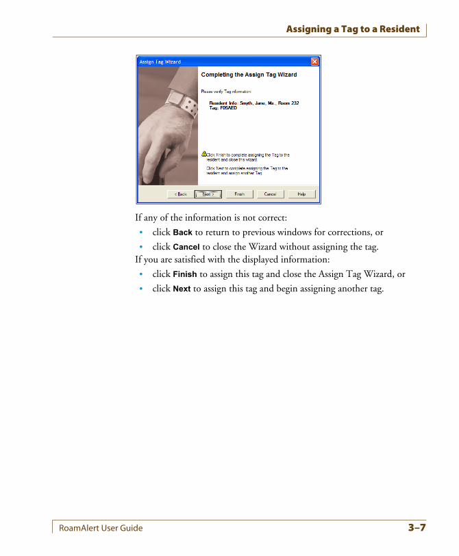
If any of the information is not correct:
• click Back to return to previous windows for corrections, or
• click Cancel to close the Wizard without assigning the tag.If you are satisfied with the displayed information:
• click Finish to assign this tag and close the Assign Tag Wizard, or
• click Next to assign this tag and begin assigning another tag.
RoamAlert User Guide 3–7
Attaching and Storing Tags
Attaching and Storing Tags
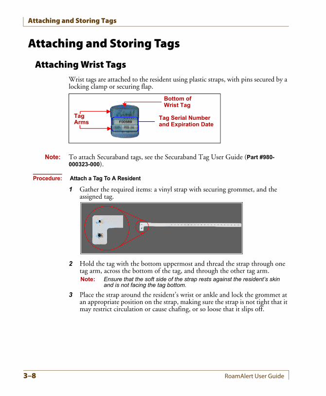
Attaching Wrist TagsWrist tags are attached to the resident using plastic straps, with pins secured by a locking clamp or securing flap.
Note: To attach Securaband tags, see the Securaband Tag User Guide (Part #980-000323-000).
Procedure: Attach a Tag To A Resident
1 Gather the required items: a vinyl strap with securing grommet, and the assigned tag.
2 Hold the tag with the bottom uppermost and thread the strap through one tag arm, across the bottom of the tag, and through the other tag arm.Note: Ensure that the soft side of the strap rests against the resident’s skin
and is not facing the tag bottom.
3 Place the strap around the resident’s wrist or ankle and lock the grommet at an appropriate position on the strap, making sure the strap is not tight that it may restrict circulation or cause chafing, or so loose that it slips off.
TagArms
Bottom ofWrist Tag
Tag Serial Numberand Expiration Date
3–8 RoamAlert User Guide
Attaching and Storing Tags
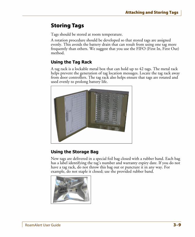
Storing TagsTags should be stored at room temperature.A rotation procedure should be developed so that stored tags are assigned evenly. This avoids the battery drain that can result from using one tag more frequently than others. We suggest that you use the FIFO (First In, First Out) method.
Using the Tag RackA tag rack is a lockable metal box that can hold up to 42 tags. The metal rack helps prevent the generation of tag location messages. Locate the tag rack away from door controllers. The tag rack also helps ensure that tags are rotated and used evenly to prolong battery life.
Using the Storage BagNew tags are delivered in a special foil bag closed with a rubber band. Each bag has a label identifying the tag’s number and warranty expiry date. If you do not have a tag rack, do not throw this bag out or puncture it in any way. For example, do not staple it closed; use the provided rubber band.
RoamAlert User Guide 3–9
Editing Resident Information
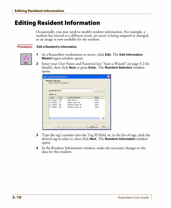
Editing Resident InformationOccasionally, you may need to modify resident information. For example, a resident has moved to a different room, an escort is being assigned or changed, or an image is now available for the resident.
Procedure: Edit a Resident’s Information
1 At a RoamAlert workstation or server, click Edit. The Edit Information Wizard logon window opens.
2 Enter your User Name and Password (see “Start a Wizard” on page 3-2 for details), then click Next or press Enter. The Resident Selection window opens.
3 Type the tag’s number into the Tag ID field, or, in the list of tags, click the desired tag to select it, then click Next. The Resident Information window opens.
4 In the Resident Information window, make the necessary changes to the data for this resident.
3–10 RoamAlert User Guide
Editing Resident Information
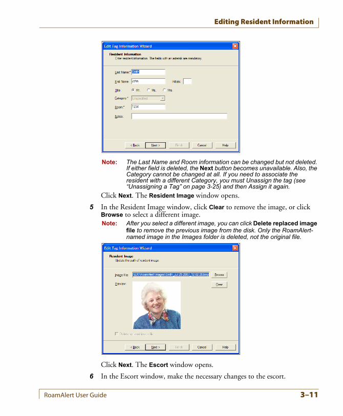
Note: The Last Name and Room information can be changed but not deleted. If either field is deleted, the Next button becomes unavailable. Also, the Category cannot be changed at all. If you need to associate the resident with a different Category, you must Unassign the tag (see “Unassigning a Tag” on page 3-25) and then Assign it again.
Click Next. The Resident Image window opens.
5 In the Resident Image window, click Clear to remove the image, or click Browse to select a different image.Note: After you select a different image, you can click Delete replaced image
file to remove the previous image from the disk. Only the RoamAlert-named image in the Images folder is deleted, not the original file.
Click Next. The Escort window opens.
6 In the Escort window, make the necessary changes to the escort.
RoamAlert User Guide 3–11
Editing Resident Information
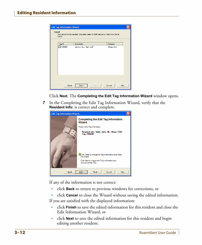
Click Next. The Completing the Edit Tag Information Wizard window opens.
7 In the Completing the Edit Tag Information Wizard, verify that the Resident Info: is correct and complete.
If any of the information is not correct:
• click Back to return to previous windows for corrections, or
• click Cancel to close the Wizard without saving the edited information.If you are satisfied with the displayed information:
• click Finish to save the edited information for this resident and close the Edit Information Wizard, or
• click Next to save the edited information for this resident and begin editing another resident.
3–12 RoamAlert User Guide
Transporting a Resident
Transporting a ResidentYou may need to move a resident out of the protected RoamAlert perimeter, for example, to take the resident to another part of the facility for tests or for the resident to go home for the weekend.Using the Transport Wizard, you can log the tag out of the system (transport the tag) for up to 72 hours. During this period, RoamAlert will not respond to Exit alarms (TIFs) or the absence of Tag Location messages (TLMs).A tag can be transported from any workstation, however, you must have at least Supervisor access to the RoamAlert software to perform this procedure.
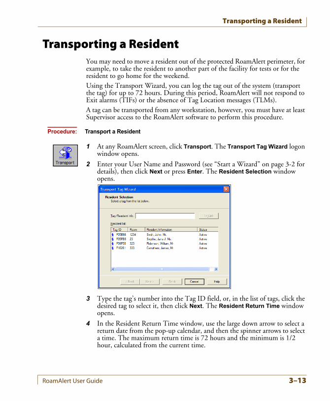
Procedure: Transport a Resident
1 At any RoamAlert screen, click Transport. The Transport Tag Wizard logon window opens.
2 Enter your User Name and Password (see “Start a Wizard” on page 3-2 for details), then click Next or press Enter. The Resident Selection window opens.
3 Type the tag’s number into the Tag ID field, or, in the list of tags, click the desired tag to select it, then click Next. The Resident Return Time window opens.
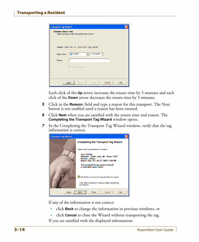
4 In the Resident Return Time window, use the large down arrow to select a return date from the pop-up calendar, and then the spinner arrows to select a time. The maximum return time is 72 hours and the minimum is 1/2 hour, calculated from the current time.
RoamAlert User Guide 3–13
Transporting a Resident
Each click of the Up arrow increases the return time by 5 minutes and each click of the Down arrow decreases the return time by 5 minutes.
5 Click in the Reason: field and type a reason for this transport. The Next button is not enabled until a reason has been entered.
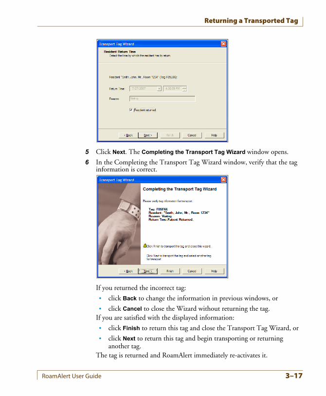
6 Click Next when you are satisfied with the return time and reason. The Completing the Transport Tag Wizard window opens.
7 In the Completing the Transport Tag Wizard window, verify that the tag information is correct.
If any of the information is not correct:
• click Back to change the information in previous windows, or
• click Cancel to close the Wizard without transporting the tag.If you are satisfied with the displayed information:
3–14 RoamAlert User Guide
Transporting a Resident
• click Finish to transport this tag and close the wizard, or
• click Next to transport this tag and begin transporting another tag.The tag is transported and RoamAlert ignores all alarms until the specified return time. You can now take the resident through an exit door.
Notes:
ReturnWarnings and
Alarms
• A warning is issued at the RoamAlert workstation 15 minutes before the transport time period ends. If the tag has still not returned by the specified return time, an alarm is issued.
ExtendingTransport Time
• If you require more time outside the RoamAlert perimeter than specified, you can contact an authorized user to extend the transport time by repeating the above procedure.
Anti-PiggybackingNormally, when a transported tag enters the field of a door controller, the controller does not lock the door or generate an alarm, and the tag can pass through the door. Similarly, at an elevator, the controller does not lock the cab door open or generate an alarm and the tag can travel off the floor.The RoamAlert Anti-Piggybacking feature prevents non-transported tags from passing through an exit immediately after a transported tag (piggybacking). If a controller detects an additional non-transported tag, bypass is terminated, the door is locked (open at an elevator), and an alarm is generated.
RoamAlert User Guide 3–15
Returning a Transported Tag
Returning a Transported TagOnly a Supervisor or Administrator can return a transported tag, either using the Transport Wizard or using the tag’s property sheet in the Tags panel. See “Editing Tag Properties” on page 7-15 for property sheet information.
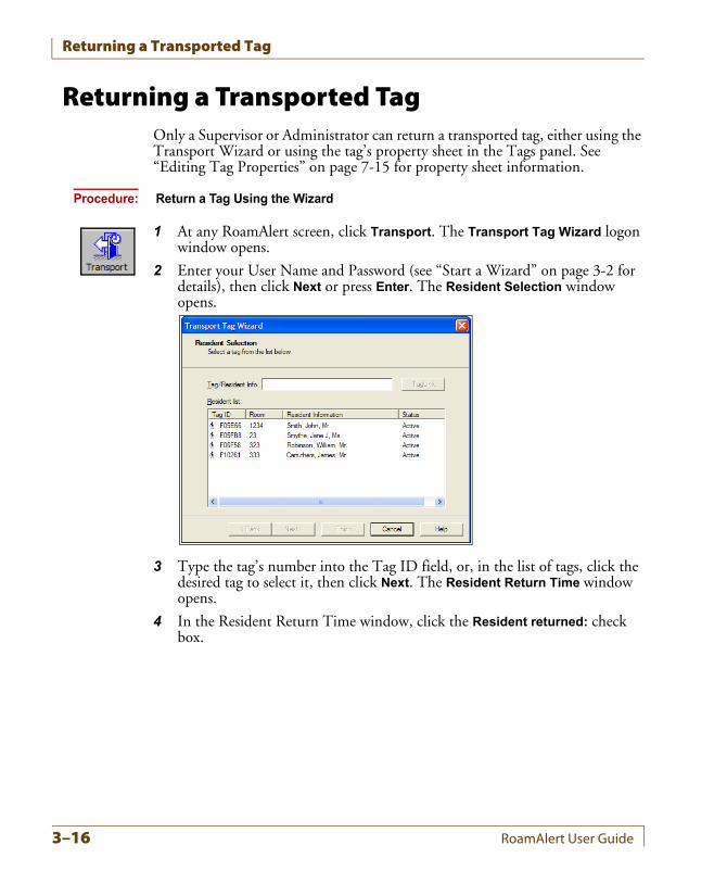
Procedure: Return a Tag Using the Wizard
1 At any RoamAlert screen, click Transport. The Transport Tag Wizard logon window opens.
2 Enter your User Name and Password (see “Start a Wizard” on page 3-2 for details), then click Next or press Enter. The Resident Selection window opens.
3 Type the tag’s number into the Tag ID field, or, in the list of tags, click the desired tag to select it, then click Next. The Resident Return Time window opens.
4 In the Resident Return Time window, click the Resident returned: check box.
3–16 RoamAlert User Guide
Returning a Transported Tag
5 Click Next. The Completing the Transport Tag Wizard window opens.
6 In the Completing the Transport Tag Wizard window, verify that the tag information is correct.
If you returned the incorrect tag:
• click Back to change the information in previous windows, or
• click Cancel to close the Wizard without returning the tag.If you are satisfied with the displayed information:
• click Finish to return this tag and close the Transport Tag Wizard, or
• click Next to return this tag and begin transporting or returning another tag.
The tag is returned and RoamAlert immediately re-activates it.
RoamAlert User Guide 3–17
Displaying the Tag Census
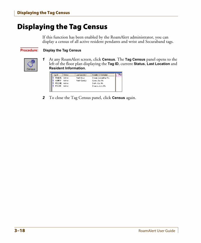
Displaying the Tag CensusIf this function has been enabled by the RoamAlert administrator, you can display a census of all active resident pendants and wrist and Securaband tags.
Procedure: Display the Tag Census
1 At any RoamAlert screen, click Census. The Tag Census panel opens to the left of the floor plan displaying the Tag ID, current Status, Last Location and Resident Information.
2 To close the Tag Census panel, click Census again.
3–18 RoamAlert User Guide
Bypassing A Door or Elevator
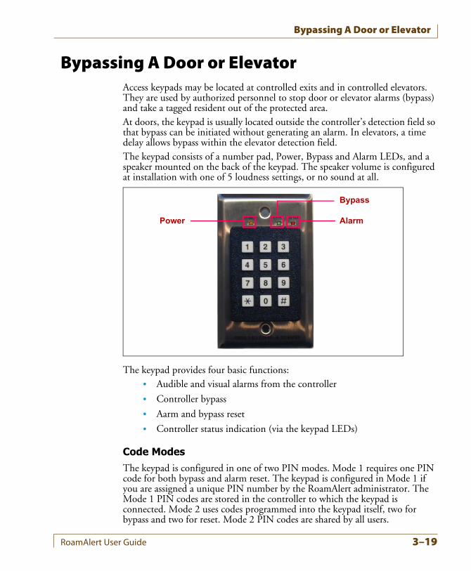
Bypassing A Door or ElevatorAccess keypads may be located at controlled exits and in controlled elevators. They are used by authorized personnel to stop door or elevator alarms (bypass) and take a tagged resident out of the protected area.At doors, the keypad is usually located outside the controller’s detection field so that bypass can be initiated without generating an alarm. In elevators, a time delay allows bypass within the elevator detection field.The keypad consists of a number pad, Power, Bypass and Alarm LEDs, and a speaker mounted on the back of the keypad. The speaker volume is configured at installation with one of 5 loudness settings, or no sound at all.
The keypad provides four basic functions:• Audible and visual alarms from the controller
• Controller bypass
• Aarm and bypass reset
• Controller status indication (via the keypad LEDs)
Code ModesThe keypad is configured in one of two PIN modes. Mode 1 requires one PIN code for both bypass and alarm reset. The keypad is configured in Mode 1 if you are assigned a unique PIN number by the RoamAlert administrator. The Mode 1 PIN codes are stored in the controller to which the keypad is connected. Mode 2 uses codes programmed into the keypad itself, two for bypass and two for reset. Mode 2 PIN codes are shared by all users.
Power
Bypass
Alarm
RoamAlert User Guide 3–19
Bypassing A Door or Elevator
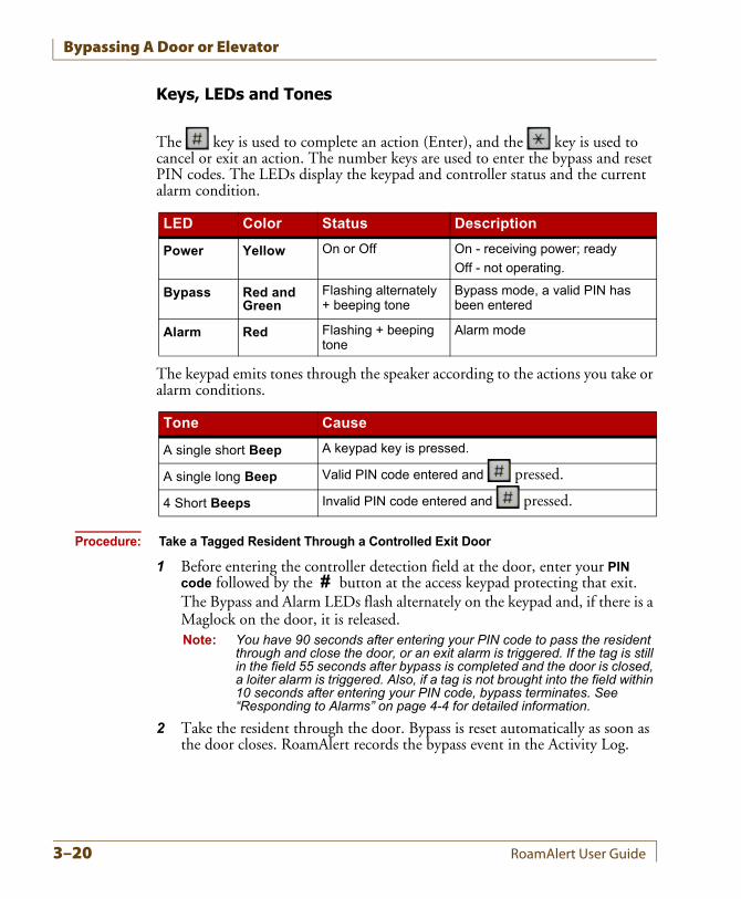
Keys, LEDs and Tones
The key is used to complete an action (Enter), and the key is used to cancel or exit an action. The number keys are used to enter the bypass and reset PIN codes. The LEDs display the keypad and controller status and the current alarm condition.
The keypad emits tones through the speaker according to the actions you take or alarm conditions.
Procedure: Take a Tagged Resident Through a Controlled Exit Door
1 Before entering the controller detection field at the door, enter your PIN code followed by the # button at the access keypad protecting that exit.The Bypass and Alarm LEDs flash alternately on the keypad and, if there is a Maglock on the door, it is released.Note: You have 90 seconds after entering your PIN code to pass the resident
through and close the door, or an exit alarm is triggered. If the tag is still in the field 55 seconds after bypass is completed and the door is closed, a loiter alarm is triggered. Also, if a tag is not brought into the field within 10 seconds after entering your PIN code, bypass terminates. See “Responding to Alarms” on page 4-4 for detailed information.
2 Take the resident through the door. Bypass is reset automatically as soon as the door closes. RoamAlert records the bypass event in the Activity Log.
LED Color Status Description
Power Yellow On or Off On - receiving power; ready
Off - not operating.
Bypass Red and Green
Flashing alternately + beeping tone
Bypass mode, a valid PIN has been entered
Alarm Red Flashing + beeping tone
Alarm mode
Tone Cause
A single short Beep A keypad key is pressed.
A single long Beep Valid PIN code entered and pressed.
4 Short Beeps Invalid PIN code entered and pressed.
3–20 RoamAlert User Guide
Bypassing A Door or Elevator
Procedure: Take a Tagged Resident Into a Controlled Elevator
1 As you enter the elevator with the resident, the tag is detected by the controller, the elevator door is locked in the open position and the access keypad emits warning beeps.
2 At the access keypad inside the elevator, enter your PIN code followed by the # button within 10 seconds.
3 If you enter a valid PIN code, the elevator door closes, the keypad resets and RoamAlert records the bypass event in the Activity Log.Note: If the PIN code is not entered within 10 seconds or it is invalid, an exit
alarm is triggered and the elevator door remains locked open. See “Responding to Alarms” on page 4-4 for detailed information.
PendantsIf you are wearing a pendant which is associated with a Category that allows access to a specific controller, you can move through that protected exit or elevator without using the access keypad. Specifically:
• Maglock controlled doors will unlock when the pendant enters the controller detection field,
• the elevator controller will not lock the door open,
• no messages appear on any workstation or server screen, but
• the bypass event is recorded in the Activity Log.
Transport Anti-PiggybackingWhen a tag that has been transported is detected by a controller, the door or elevator is automatically bypassed. However, if the controller detects a non-transported tag following immediately into the field, bypass is terminated and an alarm is generated.
RoamAlert User Guide 3–21
Locating Tags
Locating TagsYou can locate any assigned pulse technology tag on the floor plans at the server or a workstation in a RoamAlert facility with receivers, as long as the pulse function on the tag is enabled. The pulse function, which causes the tag to emit TLMs (tag location messages) at regular intervals, is configured either at the factory or with a Pocket Tag Reader (PTR) (see document 980-000010-000 for details). When the tag is added to inventory or later on the tag’s property sheet, the software can be configured to look for tag pulses from the tag. See “Adding New Tags to Inventory” on page 7-4 or “Editing Tag Properties” on page 7-15 for details.The Locate function can be performed by any RoamAlert user at either the server or a workstation.
Locating Tags in a FacilityIn a facility with receivers, you can locate one or multiple assigned pulse tags in several ways, including:
• system-wide – all tags in the system,
• by floor – all tags on the selected floor or floors,
• by tag type – all tags of the selected type (resident, staff, etc.),
• by category – all tags in the selected category,
• by tag description – the specific tag matching the description, or
• by a combination of the above methods, for example, all wrist tags on the third floor.
The Locate function always displays the most recent location of the tag. If you are a Supervisor or Administrator you can view the last 10 locations of any tag on the Location tab of the tag’s property sheet. See “Edit the Properties of a Tag” on page 7-15 for details. You can also view the tag’s prior location history using the search function in the Activity Logs tab. See “Search the Activity Log for Specific Entries” on page 5-5 for details.
Procedure: Locate Tags in a Facility
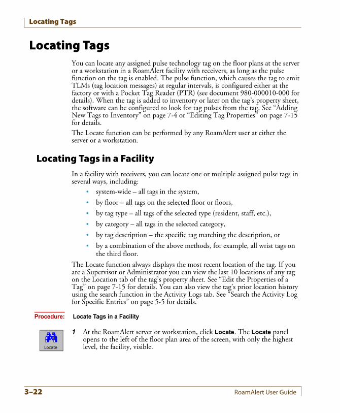
1 At the RoamAlert server or workstation, click Locate. The Locate panel opens to the left of the floor plan area of the screen, with only the highest level, the facility, visible.
3–22 RoamAlert User Guide
Locating Tags
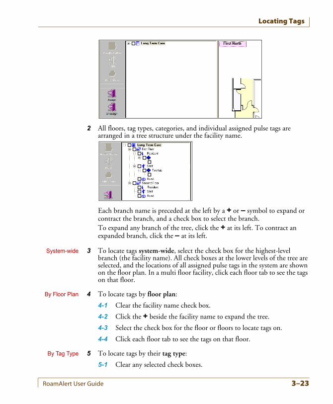
2 All floors, tag types, categories, and individual assigned pulse tags are arranged in a tree structure under the facility name.
Each branch name is preceded at the left by a + or – symbol to expand or contract the branch, and a check box to select the branch.To expand any branch of the tree, click the + at its left. To contract an expanded branch, click the – at its left.
System-wide 3 To locate tags system-wide, select the check box for the highest-level branch (the facility name). All check boxes at the lower levels of the tree are selected, and the locations of all assigned pulse tags in the system are shown on the floor plan. In a multi floor facility, click each floor tab to see the tags on that floor.
By Floor Plan 4 To locate tags by floor plan:
4-1 Clear the facility name check box.
4-2 Click the + beside the facility name to expand the tree.
4-3 Select the check box for the floor or floors to locate tags on.
4-4 Click each floor tab to see the tags on that floor.
By Tag Type 5 To locate tags by their tag type:
5-1 Clear any selected check boxes.
RoamAlert User Guide 3–23
Locating Tags
5-2 Click the + beside a floor to expand its tree.
5-3 Select the check box for the tag type to locate.
5-4 Click the floor’s tab to see the tags in the selected type.
By Category 6 To locate tags by category (if categories are associated with tags).
6-1 Clear any selected check boxes.
6-2 Click the + beside a floor and tag type to expand the tree.
6-3 Select the check box for the category to locate.
6-4 Click the floor’s tab to see the tags in the selected category.
Individually 7 To locate an individual tag:
7-1 Clear any selected check boxes.
7-2 Click the + beside a floor, tag type, and category to expand the tree.
7-3 Select the check box for the tag to locate.
7-4 Click the floor’s tab to see the selected tag.
3–24 RoamAlert User Guide
Unassigning a Tag
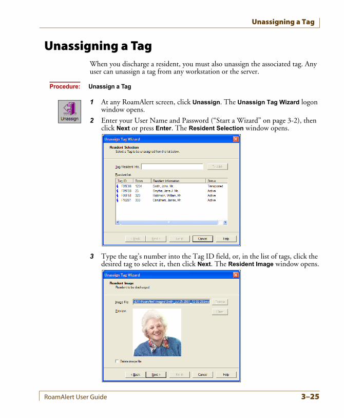
Unassigning a TagWhen you discharge a resident, you must also unassign the associated tag. Any user can unassign a tag from any workstation or the server.
Procedure: Unassign a Tag
1 At any RoamAlert screen, click Unassign. The Unassign Tag Wizard logon window opens.
2 Enter your User Name and Password (“Start a Wizard” on page 3-2), then click Next or press Enter. The Resident Selection window opens.
3 Type the tag’s number into the Tag ID field, or, in the list of tags, click the desired tag to select it, then click Next. The Resident Image window opens.
RoamAlert User Guide 3–25
Unassigning a Tag
4 To remove the RoamAlert-created image file, select the Delete image file check box, then click Next. The Completing the Unassign Tag Wizard window opens.
5 In the Completing the Unassign Tag Wizard window, verify that the Resident Info: is correct.
If you have not selected the correct tag:
• click Back to return to the Resident Selection window and select a different tag, or
• click Cancel to close the Wizard without unassigning the tag.Note: If you selected Delete image file, but did not select the correct tag, the
image file is removed and you must edit the tag information to replace the image file (see “Edit a Resident’s Information” on page 3-10).
If the information is correct:
• click Finish to unassign the tag and close the Unassign Tag Wizard, or
• click Next to unassign this tag and begin to unassign another tag.
6 Return the tag for cleaning and storage (see “Testing and Cleaning Tags” on page 7-11).
3–26 RoamAlert User Guide
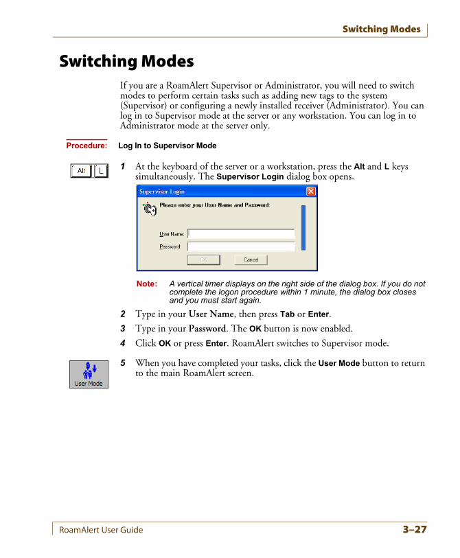
Switching Modes
Switching ModesIf you are a RoamAlert Supervisor or Administrator, you will need to switch modes to perform certain tasks such as adding new tags to the system (Supervisor) or configuring a newly installed receiver (Administrator). You can log in to Supervisor mode at the server or any workstation. You can log in to Administrator mode at the server only.
Procedure: Log In to Supervisor Mode
1 At the keyboard of the server or a workstation, press the Alt and L keys simultaneously. The Supervisor Login dialog box opens.
Note: A vertical timer displays on the right side of the dialog box. If you do not complete the logon procedure within 1 minute, the dialog box closes and you must start again.
2 Type in your User Name, then press Tab or Enter.
3 Type in your Password. The OK button is now enabled.
4 Click OK or press Enter. RoamAlert switches to Supervisor mode.
5 When you have completed your tasks, click the User Mode button to return to the main RoamAlert screen.
RoamAlert User Guide 3–27
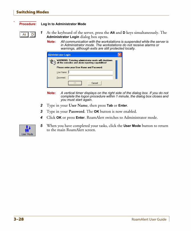
Switching Modes
Procedure: Log In to Administrator Mode
1 At the keyboard of the server, press the Alt and D keys simultaneously. The Administrator Login dialog box opens.Note: All communication with the workstations is suspended while the server is
in Administrator mode. The workstations do not receive alarms or warnings, although exits are still protected locally.
Note: A vertical timer displays on the right side of the dialog box. If you do not complete the logon procedure within 1 minute, the dialog box closes and you must start again.
2 Type in your User Name, then press Tab or Enter.
3 Type in your Password. The OK button is now enabled.
4 Click OK or press Enter. RoamAlert switches to Administrator mode.
5 When you have completed your tasks, click the User Mode button to return to the main RoamAlert screen.
3–28 RoamAlert User Guide
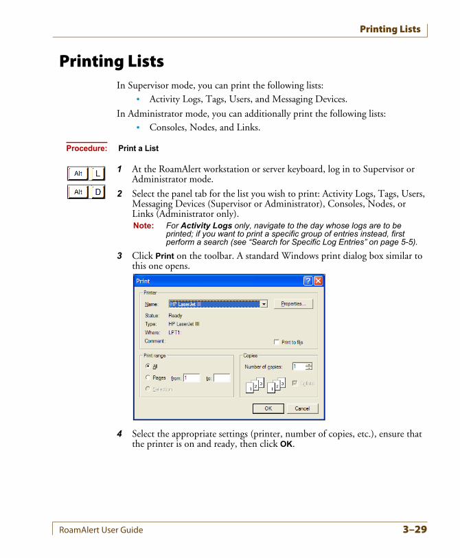
Printing Lists
Printing ListsIn Supervisor mode, you can print the following lists:
• Activity Logs, Tags, Users, and Messaging Devices.
In Administrator mode, you can additionally print the following lists:• Consoles, Nodes, and Links.
Procedure: Print a List
1 At the RoamAlert workstation or server keyboard, log in to Supervisor or Administrator mode.
2 Select the panel tab for the list you wish to print: Activity Logs, Tags, Users, Messaging Devices (Supervisor or Administrator), Consoles, Nodes, or Links (Administrator only).Note: For Activity Logs only, navigate to the day whose logs are to be
printed; if you want to print a specific group of entries instead, first perform a search (see “Search for Specific Log Entries” on page 5-5).
3 Click Print on the toolbar. A standard Windows print dialog box similar to this one opens.
4 Select the appropriate settings (printer, number of copies, etc.), ensure that the printer is on and ready, then click OK.
RoamAlert User Guide 3–29
Printing Lists
3–30 RoamAlert User Guide
Chapter 4CHAPTER 0RESPONDING TO ALARMS
RoamAlert alarm response procedures include:
• Accepting alarms at the server or workstation
• Accepting alarms at an access keypad
• Muting alarm sounds
Any authorized RoamAlert user can respond to an alarm. Each facility should devise its own policies and procedures for responding to alarms, and should identify the users who will be responsible for carrying out the procedures.Establishing and maintaining alarm response procedures is essential for the security of your residents and staff. The descriptions in this chapter illustrate how the RoamAlert software and components are used to carry out these procedures.
RoamAlert User Guide 4–1
About Tag Alarms
About Tag AlarmsRoamAlert automatically generates alarm messages when certain events occur. In day-to-day operations, these alarms usually relate to changes in the status of tags. Tag alarms are generated under these conditions:
• When a tag enters the field of an open controlled door (Tag In Field or TIF), or remains in the field longer than 55 seconds without the entry of a valid PIN code at the access keypad
• When an unassigned or non-transported tag enters a controlled elevator (TIF) and remains longer than 10 seconds without the entry of a valid PIN code at the elevator’s access keypad
• When the system cannot detect the pulse signal (Tag Location Message or TLM) of a tag (if this functionality is configured, and receivers are installed)
• When the panic button on a pendant is pressed (Tag Initiated Communication or TIC)
• When the cord on the pull cord unit is pulled (TIC)
• When a tag’s battery circuit sends a low-battery signal (Battery Low Message or BLM)
The behavior of some alarms is set in the software. For example:
• pulse wrist tags (green), emit a signal (TLM) every 16 seconds. The number of missed pulses before RoamAlert issues a warning or an alarm is configurable, or this feature may be turned off completely.
• RoamAlert may be configured to ignore unassigned tags at exits.
Other alarms are generated for certain system events, such as the communications failure of a controller or receiver. See “About System Alarms” on page 4-6.If there is more than one workstation in your facility, each workstation may be configured to display only certain alarm types, only alarms from certain nodes, or only alarms from a specific range of tag ID numbers. For example, on a large floor, there may be exit doors at each end and an elevator bank and stairwell in the central area. In such a layout, the server may be centrally located and one workstation located near each exit door. Alarms of all types and from all nodes may be displayed at the server, while exit alarms from the doors may be displayed only on the closest workstation.
4–2 RoamAlert User Guide
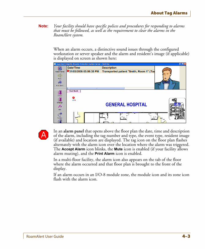
About Tag Alarms
Note: Your facility should have specific polices and procedures for responding to alarms that must be followed, as well as the requirement to clear the alarms in the RoamAlert system.
When an alarm occurs, a distinctive sound issues through the configured workstation or server speaker and the alarm and resident’s image (if applicable) is displayed on screen as shown here:
In an alarm panel that opens above the floor plan the date, time and description of the alarm, including the tag number and type, the event type, resident image (if available) and location are displayed. The tag icon on the floor plan flashes alternately with the alarm icon over the location where the alarm was triggered. The Accept Alarm icon blinks, the Mute icon is enabled (if your facility allows alarm muting), and the Print Alarm icon is enabled.In a multi-floor facility, the alarm icon also appears on the tab of the floor where the alarm occurred and that floor plan is brought to the front of the display.If an alarm occurs in an I/O-8 module zone, the module icon and its zone icon flash with the alarm icon.
RoamAlert User Guide 4–3
Responding to Alarms
Responding to Alarms
Accepting Alarms at a Workstation or ServerWhen an alarm occurs, the flashing alarm icon appears on the floor plan where the alarm was triggered, the alarm panel opens to display the alarm description, and the alarm sound is heard over the workstation speaker.Depending on the policies in place at your facility, door controllers may be configured in a “latching” mode that requires you to accept an alarm at the door as well as at the PC.
Procedure: Accept an Alarm at the Server or a Workstation
Important: 1 Immediately follow your facility’s procedures for resident or staff protection when responding to an alarm.
2 At the server or workstation displaying the alarm, click the description of the alarm to select it.Note: If there is more than one alarm that you want to accept with the same
annotation, press and hold the Shift or Ctrl keys while selecting alarms.
3 Alarms can only be printed before they are accepted. If your facility requires a printed record of alarms, click Print Alarm then, in the Print dialog, select the printer and click OK.
4 Click Accept Alarm, or double-click the alarm description in the alarm panel. The Accept Alarm Wizard logon window opens.
5 Enter your User Name and Password (for details, see “Start a Wizard” on page 3-2), then click Next or press Enter. The Alarm Note window opens, displaying the alarm or alarms you have selected.The Finish button is not enabled until a Note is entered or selected.
4–4 RoamAlert User Guide
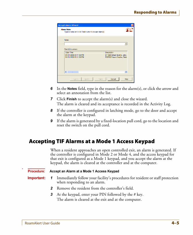
Responding to Alarms
6 In the Notes field, type in the reason for the alarm(s), or click the arrow and select an annotation from the list.
7 Click Finish to accept the alarm(s) and close the wizard.The alarm is cleared and its acceptance is recorded in the Activity Log.
8 If the controller is configured in latching mode, go to the door and accept the alarm at the keypad.
9 If the alarm is generated by a fixed-location pull cord, go to the location and reset the switch on the pull cord.
Accepting TIF Alarms at a Mode 1 Access KeypadWhen a resident approaches an open controlled exit, an alarm is generated. If the controller is configured in Mode 2 or Mode 4, and the access keypad for that exit is configured as a Mode 1 keypad, and you accept the alarm at the keypad, the alarm is cleared at the controller and at the computer.
Procedure: Accept an Alarm at a Mode 1 Access Keypad
Important: 1 Immediately follow your facility’s procedures for resident or staff protection when responding to an alarm.
2 Remove the resident from the controller’s field.
3 At the keypad, enter your PIN followed by the # key.The alarm is cleared at the exit and at the computer.
RoamAlert User Guide 4–5
Responding to Alarms
Muting Alarm SoundsWhen an alarm occurs, RoamAlert issues a distinctive sound through the workstation or server speaker. This sound repeats until the alarm is accepted. If your facility policy allows, you can mute (turn off) the sound for up to 5 minutes by clicking the Mute button. If your facility does not allow muting, the Mute button is unavailable (gray).Any user can mute the alarm at the workstation or server.
Procedure: Mute an Alarm
• At the RoamAlert workstation that generated the alarm, click Mute. The alarm sound is turned off, and the Mute button changes to its activated state. If the alarm is not accepted within 5 minutes, or another alarm is received, the sound is automatically turned on again and the Mute button reverts to its normal state.
Handling Low Battery AlarmsEach tag has an internal circuit that detects when the battery is depleted to the point that it should be replaced. When this happens, the tag emits a low-battery alarm signal (BLM) and, if the tag is in range of a controller or receiver, an alarm is issued at the appropriate workstations.RoamAlert changes the status of the tag to Disabled - Low Battery. If the tag is unassigned at the time of the alarm, the Assign Tag Wizard will no longer allow it to be assigned. If the tag is assigned, immediately unassign the tag and assign a new tag to the resident or staff member. See “Assigning a Tag to a Resident” on page 3-3 for details.RoamAlert tags are sealed units; the battery cannot be replaced.
About System AlarmsWhen a controller or receiver is not communicating correctly with the server, or a device such as an exciter has failed, the failure icon flashes on the node icon and on the floor plan tab.
Alarm RemindersAt 09:00 (9 AM) each day, RoamAlert issues alarms for node failures or for transport expired tags that persist after the alarms have been cleared.
4–6 RoamAlert User Guide
Chapter 5CHAPTER 0ACTIVITY LOGS
Every event (warnings, alarms, logon attempts, tag activity, communication errors, etc.) that occurs in the RoamAlert system is stored in the Activity Log.RoamAlert activity log procedures include:
• Viewing the activity logs
• Annotating an activity log entry
• Searching for specific activity log entries
The descriptions in this chapter illustrate how the RoamAlert software is used to carry out these procedures.RoamAlert Activity Log functions are available only in Supervisor or Administrator mode, therefore you must have at least Supervisor access to use these functions.The Log can be viewed at the server or any workstation. RoamAlert automatically updates the workstation logs whenever the server records any system activity.Also supplied on the RoamAlert CD is a software tool called the eLinkActivityViewer that you can install and use to view activity logs. You can export logs as .csv (Comma Separated Value) files from the Ativity Viewer for further analysis and charting in a spreadsheet or other suitable program that can read .csv files.
RoamAlert User Guide 5–1
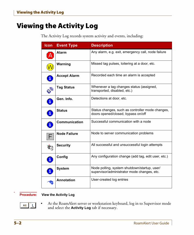
Viewing the Activity Log
Viewing the Activity LogThe Activity Log records system activity and events, including:
Procedure: View the Activity Log
• At the RoamAlert server or workstation keyboard, log in to Supervisor mode and select the Activity Log tab if necessary.
Icon Event Type Description
Alarm Any alarm, e.g. exit, emergency call, node failure
Warning Missed tag pulses, loitering at a door, etc.
Accept Alarm Recorded each time an alarm is accepted
Tag Status Whenever a tag changes status (assigned, transported, disabled, etc.)
Gen. Info. Detections at door, etc.
Status Status changes, such as controller mode changes, doors opened/closed, bypass on/off
Communication Successful communication with a node
Node Failure Node to server communication problems
Security All successful and unsuccessful login attempts
Config Any configuration change (add tag, edit user, etc.)
System Node polling, system shutdown/startup, user/supervisor/administrator mode changes, etc.
Annotation User-created log entries
5–2 RoamAlert User Guide
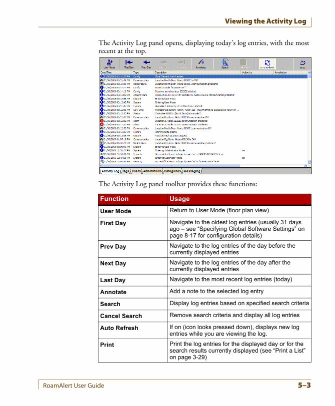
Viewing the Activity Log
The Activity Log panel opens, displaying today’s log entries, with the most recent at the top.
The Activity Log panel toolbar provides these functions:
Function Usage
User Mode Return to User Mode (floor plan view)
First Day Navigate to the oldest log entries (usually 31 days ago – see “Specifying Global Software Settings” on page 8-17 for configuration details)
Prev Day Navigate to the log entries of the day before the currently displayed entries
Next Day Navigate to the log entries of the day after the currently displayed entries
Last Day Navigate to the most recent log entries (today)
Annotate Add a note to the selected log entry
Search Display log entries based on specified search criteria
Cancel Search Remove search criteria and display all log entries
Auto Refresh If on (icon looks pressed down), displays new log entries while you are viewing the log.
Print Print the log entries for the displayed day or for the search results currently displayed (see “Print a List” on page 3-29)
RoamAlert User Guide 5–3
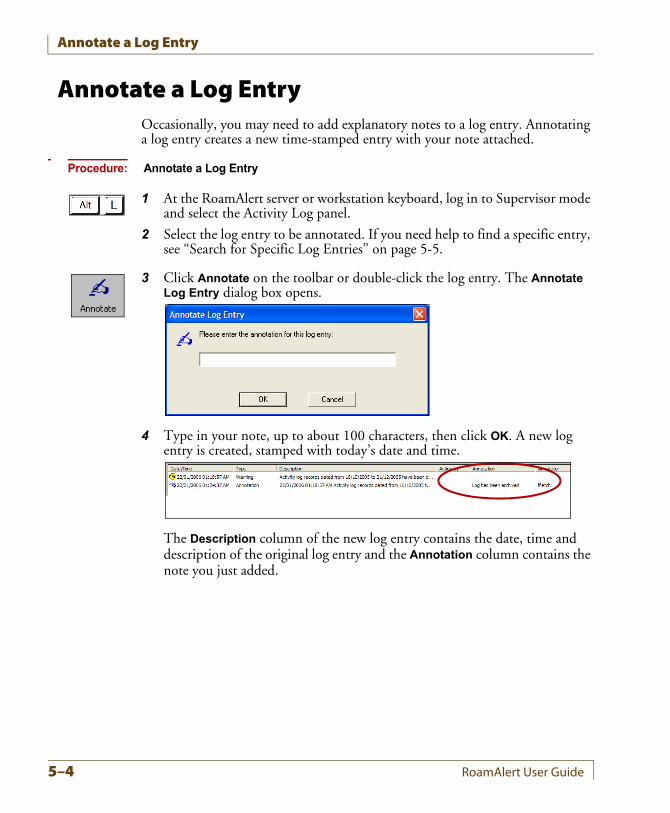
Annotate a Log Entry
Annotate a Log EntryOccasionally, you may need to add explanatory notes to a log entry. Annotating a log entry creates a new time-stamped entry with your note attached.
Procedure: Annotate a Log Entry
1 At the RoamAlert server or workstation keyboard, log in to Supervisor mode and select the Activity Log panel.
2 Select the log entry to be annotated. If you need help to find a specific entry, see “Search for Specific Log Entries” on page 5-5.
3 Click Annotate on the toolbar or double-click the log entry. The Annotate Log Entry dialog box opens.
4 Type in your note, up to about 100 characters, then click OK. A new log entry is created, stamped with today’s date and time.
The Description column of the new log entry contains the date, time and description of the original log entry and the Annotation column contains the note you just added.
5–4 RoamAlert User Guide
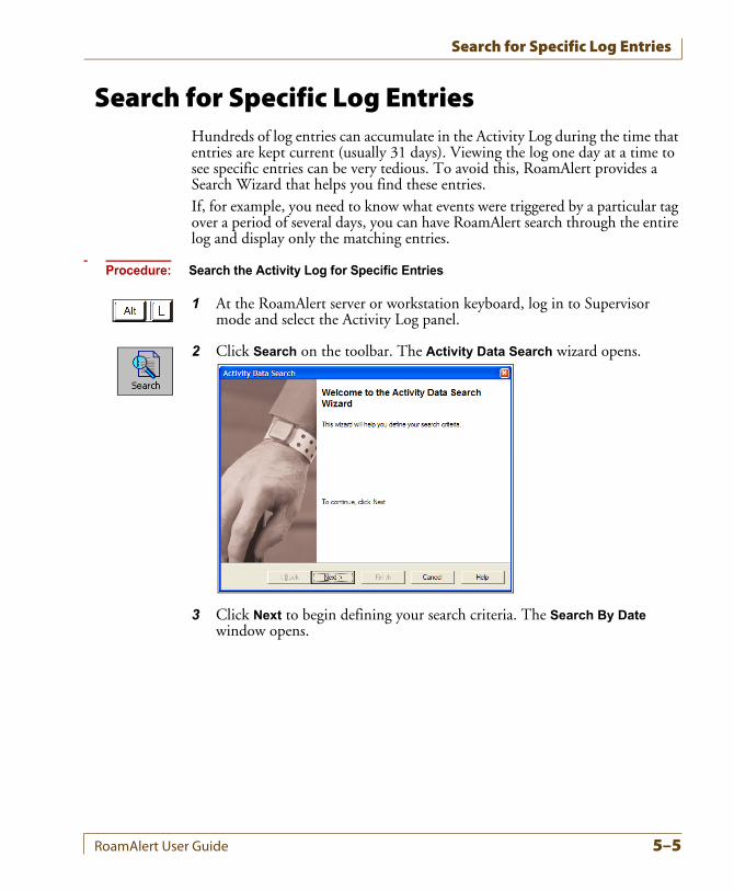
Search for Specific Log Entries
Search for Specific Log EntriesHundreds of log entries can accumulate in the Activity Log during the time that entries are kept current (usually 31 days). Viewing the log one day at a time to see specific entries can be very tedious. To avoid this, RoamAlert provides a Search Wizard that helps you find these entries.If, for example, you need to know what events were triggered by a particular tag over a period of several days, you can have RoamAlert search through the entire log and display only the matching entries.
Procedure: Search the Activity Log for Specific Entries
1 At the RoamAlert server or workstation keyboard, log in to Supervisor mode and select the Activity Log panel.
2 Click Search on the toolbar. The Activity Data Search wizard opens.
3 Click Next to begin defining your search criteria. The Search By Date window opens.
RoamAlert User Guide 5–5
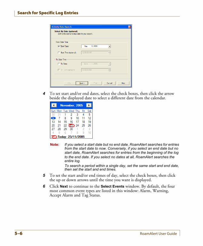
Search for Specific Log Entries
4 To set start and/or end dates, select the check boxes, then click the arrow beside the displayed date to select a different date from the calendar.
Note: If you select a start date but no end date, RoamAlert searches for entries from the start date to now. Conversely, if you select an end date but no start date, RoamAlert searches for entries from the beginning of the log to the end date. If you select no dates at all, RoamAlert searches the entire log.To search a period within a single day, set the same start and end date, then set the start and end times.
5 To set the start and/or end times of day, select the check boxes, then click the up or down arrows until the time you want is displayed.
6 Click Next to continue to the Select Events window. By default, the four most common event types are listed in this window: Alarm, Warning, Accept Alarm and Tag Status.
5–6 RoamAlert User Guide
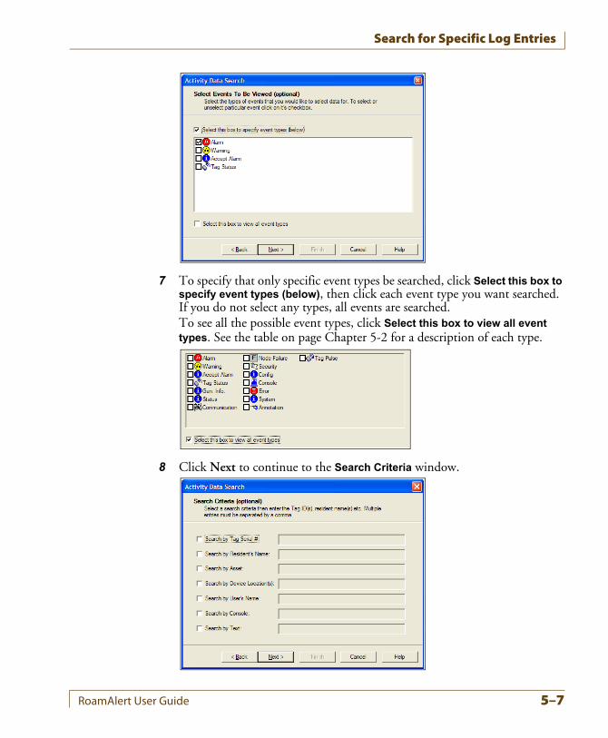
Search for Specific Log Entries
7 To specify that only specific event types be searched, click Select this box to specify event types (below), then click each event type you want searched. If you do not select any types, all events are searched.To see all the possible event types, click Select this box to view all event types. See the table on page Chapter 5-2 for a description of each type.
8 Click Next to continue to the Search Criteria window.
RoamAlert User Guide 5–7
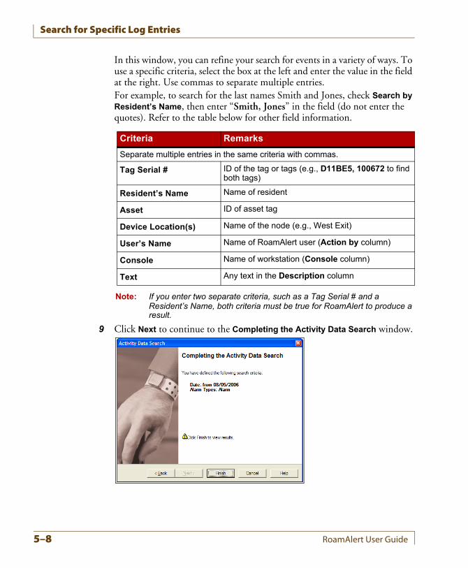
Search for Specific Log Entries
In this window, you can refine your search for events in a variety of ways. To use a specific criteria, select the box at the left and enter the value in the field at the right. Use commas to separate multiple entries.For example, to search for the last names Smith and Jones, check Search by Resident’s Name, then enter “Smith, Jones” in the field (do not enter the quotes). Refer to the table below for other field information.
Note: If you enter two separate criteria, such as a Tag Serial # and a Resident’s Name, both criteria must be true for RoamAlert to produce a result.
9 Click Next to continue to the Completing the Activity Data Search window.
Criteria Remarks
Separate multiple entries in the same criteria with commas.
Tag Serial # ID of the tag or tags (e.g., D11BE5, 100672 to find both tags)
Resident’s Name Name of resident
Asset ID of asset tag
Device Location(s) Name of the node (e.g., West Exit)
User’s Name Name of RoamAlert user (Action by column)
Console Name of workstation (Console column)
Text Any text in the Description column
5–8 RoamAlert User Guide
Search for Specific Log Entries
10 Review your search criteria. Click Back to make changes (if necessary), then click Finish to perform the search.The window closes and RoamAlert displays the results in the Activity Log. If the log is large, the search may take several moments. If no log entries match your criteria, the Activity Log display is empty.Note: Each time you perform an Activity Data search, RoamAlert remembers
your previous settings, so you can easily adjust just some of your criteria.
11 To cancel the search and return the Activity Log to the normal display, click Cancel Search.
RoamAlert User Guide 5–9
Search for Specific Log Entries
5–10 RoamAlert User Guide
Chapter 6CHAPTER 0MANAGING USERS
User management procedures include:
• Viewing user lists
• Adding and deleting users
• Editing user properties (disable/enable, access, password, PIN, etc.)
The descriptions in this chapter illustrate how the RoamAlert software and components are used to carry out these procedures.RoamAlert user management functions are available only in Supervisor or Administrator mode, therefore you must have at least Supervisor access to use these functions. Also, note that:
• A Supervisor cannot add, delete, edit properties, or change the password or PIN of an Administrator.
• A Supervisor or Administrator cannot delete or edit his or her own record, or change his or her own password or PIN.
The user list can be viewed and managed at the server or any workstation.
RoamAlert User Guide 6–1
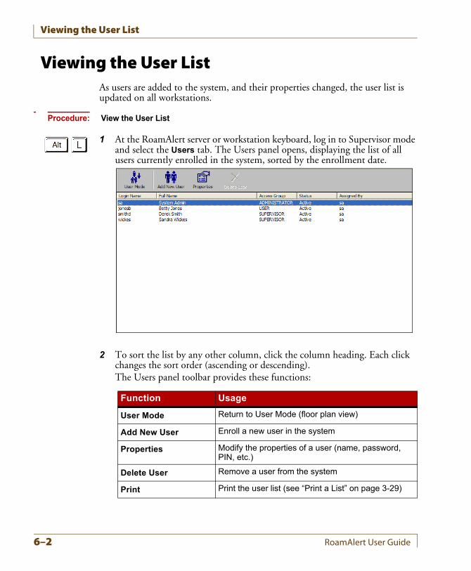
Viewing the User List
Viewing the User ListAs users are added to the system, and their properties changed, the user list is updated on all workstations.
Procedure: View the User List
1 At the RoamAlert server or workstation keyboard, log in to Supervisor mode and select the Users tab. The Users panel opens, displaying the list of all users currently enrolled in the system, sorted by the enrollment date.
2 To sort the list by any other column, click the column heading. Each click changes the sort order (ascending or descending).The Users panel toolbar provides these functions:
Function Usage
User Mode Return to User Mode (floor plan view)
Add New User Enroll a new user in the system
Properties Modify the properties of a user (name, password, PIN, etc.)
Delete User Remove a user from the system
Print Print the user list (see “Print a List” on page 3-29)
6–2 RoamAlert User Guide
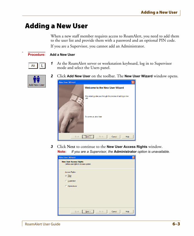
Adding a New User
Adding a New UserWhen a new staff member requires access to RoamAlert, you need to add them to the user list and provide them with a password and an optional PIN code.If you are a Supervisor, you cannot add an Administrator.
Procedure: Add a New User
1 At the RoamAlert server or workstation keyboard, log in to Supervisor mode and select the Users panel.
2 Click Add New User on the toolbar. The New User Wizard window opens.
3 Click Next to continue to the New User Access Rights window.Note: If you are a Supervisor, the Administrator option is unavailable.
RoamAlert User Guide 6–3
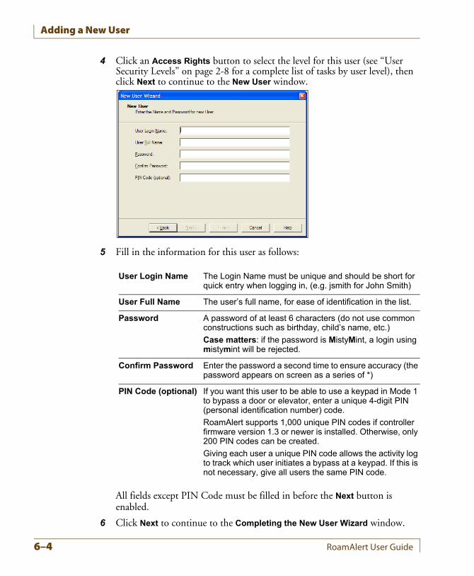
Adding a New User
4 Click an Access Rights button to select the level for this user (see “User Security Levels” on page 2-8 for a complete list of tasks by user level), then click Next to continue to the New User window.
5 Fill in the information for this user as follows:
All fields except PIN Code must be filled in before the Next button is enabled.
6 Click Next to continue to the Completing the New User Wizard window.
User Login Name The Login Name must be unique and should be short for quick entry when logging in, (e.g. jsmith for John Smith)
User Full Name The user’s full name, for ease of identification in the list.
Password A password of at least 6 characters (do not use common constructions such as birthday, child’s name, etc.)
Case matters: if the password is MistyMint, a login using mistymint will be rejected.
Confirm Password Enter the password a second time to ensure accuracy (the password appears on screen as a series of *)
PIN Code (optional) If you want this user to be able to use a keypad in Mode 1 to bypass a door or elevator, enter a unique 4-digit PIN (personal identification number) code.
RoamAlert supports 1,000 unique PIN codes if controller firmware version 1.3 or newer is installed. Otherwise, only 200 PIN codes can be created.
Giving each user a unique PIN code allows the activity log to track which user initiates a bypass at a keypad. If this is not necessary, give all users the same PIN code.
6–4 RoamAlert User Guide
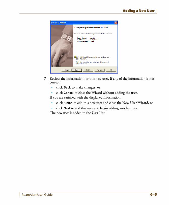
Adding a New User
7 Review the information for this new user. If any of the information is not correct:• click Back to make changes, or
• click Cancel to close the Wizard without adding the user.If you are satisfied with the displayed information:
• click Finish to add this new user and close the New User Wizard, or
• click Next to add this user and begin adding another user.The new user is added to the User List.
RoamAlert User Guide 6–5
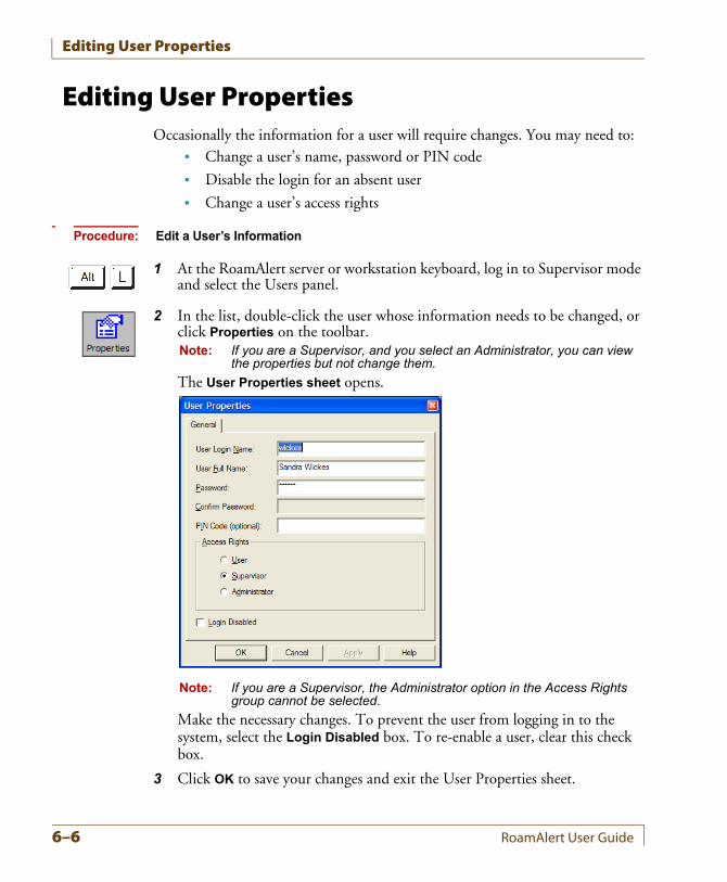
Editing User Properties
Editing User PropertiesOccasionally the information for a user will require changes. You may need to:
• Change a user’s name, password or PIN code
• Disable the login for an absent user
• Change a user’s access rights
Procedure: Edit a User’s Information
1 At the RoamAlert server or workstation keyboard, log in to Supervisor mode and select the Users panel.
2 In the list, double-click the user whose information needs to be changed, or click Properties on the toolbar.Note: If you are a Supervisor, and you select an Administrator, you can view
the properties but not change them.
The User Properties sheet opens.
Note: If you are a Supervisor, the Administrator option in the Access Rights group cannot be selected.
Make the necessary changes. To prevent the user from logging in to the system, select the Login Disabled box. To re-enable a user, clear this check box.
3 Click OK to save your changes and exit the User Properties sheet.
6–6 RoamAlert User Guide
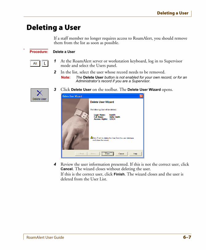
Deleting a User
Deleting a UserIf a staff member no longer requires access to RoamAlert, you should remove them from the list as soon as possible.
Procedure: Delete a User
1 At the RoamAlert server or workstation keyboard, log in to Supervisor mode and select the Users panel.
2 In the list, select the user whose record needs to be removed.Note: The Delete User button is not enabled for your own record, or for an
Administrator’s record if you are a Supervisor.
3 Click Delete User on the toolbar. The Delete User Wizard opens.
4 Review the user information presented. If this is not the correct user, click Cancel. The wizard closes without deleting the user.If this is the correct user, click Finish. The wizard closes and the user is deleted from the User List.
RoamAlert User Guide 6–7

Deleting a User
6–8 RoamAlert User Guide
Chapter 7CHAPTER 0MANAGING TAGS
Tag management procedures encompass:
• Viewing the tag list
• Adding new tags to inventory
• Deleting tags from inventory
• Testing and cleaning tags
• Determining pendant type
• Editing tag properties, which may include:
• Assigning and unassigning tags
• Enabling and disabling tags
• Changing a tag’s expiry date
• Editing resident or staff information
• Returning transported tags
The descriptions in this chapter illustrate how the RoamAlert software and components are used to carry out these procedures.RoamAlert tag management functions are available only in Supervisor or Administrator mode, therefore you must have at least Supervisor access to use these functions.The tag list can be viewed and managed at the server or any workstation.
RoamAlert User Guide 7–1
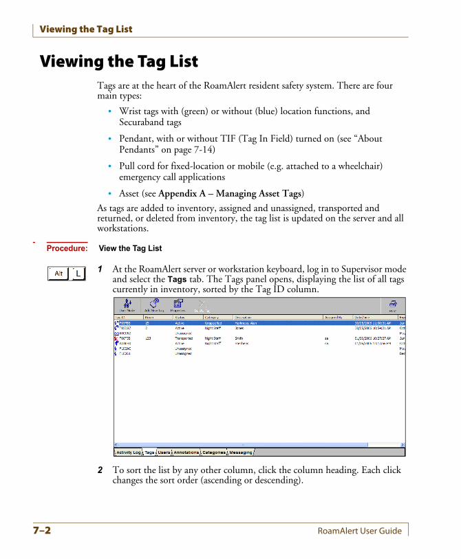
Viewing the Tag List
Viewing the Tag ListTags are at the heart of the RoamAlert resident safety system. There are four main types:
• Wrist tags with (green) or without (blue) location functions, and Securaband tags
• Pendant, with or without TIF (Tag In Field) turned on (see “About Pendants” on page 7-14)
• Pull cord for fixed-location or mobile (e.g. attached to a wheelchair) emergency call applications
• Asset (see Appendix A – Managing Asset Tags)
As tags are added to inventory, assigned and unassigned, transported and returned, or deleted from inventory, the tag list is updated on the server and all workstations.
Procedure: View the Tag List
1 At the RoamAlert server or workstation keyboard, log in to Supervisor mode and select the Tags tab. The Tags panel opens, displaying the list of all tags currently in inventory, sorted by the Tag ID column.
2 To sort the list by any other column, click the column heading. Each click changes the sort order (ascending or descending).
7–2 RoamAlert User Guide
Viewing the Tag List
The Status column contains one of the following possible entries:
The Tags panel toolbar provides these functions:
Status Description
Unassigned The tag is not assigned.
Active The tag has been assigned using the Admit icon in the main RoamAlert window or the Assign button in the tag’s property sheet.
Transported The wrist or asset tag’s exit alarm (TIF) has been disabled using the Transport icon in the main RoamAlert window.
Function Usage
User Mode Return to User Mode (floor plan view)
Add New Tag Add a new tag to inventory
Properties Modify the properties of a tag
Delete Tag Remove a tag from the system
Print Print the tag list (see “Print a List” on page 3-29)
RoamAlert User Guide 7–3
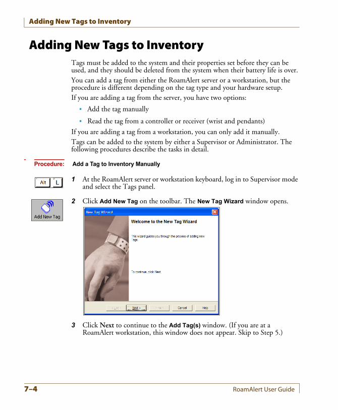
Adding New Tags to Inventory
Adding New Tags to InventoryTags must be added to the system and their properties set before they can be used, and they should be deleted from the system when their battery life is over.You can add a tag from either the RoamAlert server or a workstation, but the procedure is different depending on the tag type and your hardware setup.If you are adding a tag from the server, you have two options:
• Add the tag manually
• Read the tag from a controller or receiver (wrist and pendants)
If you are adding a tag from a workstation, you can only add it manually.Tags can be added to the system by either a Supervisor or Administrator. The following procedures describe the tasks in detail.
Procedure: Add a Tag to Inventory Manually
1 At the RoamAlert server or workstation keyboard, log in to Supervisor mode and select the Tags panel.
2 Click Add New Tag on the toolbar. The New Tag Wizard window opens.
3 Click Next to continue to the Add Tag(s) window. (If you are at a RoamAlert workstation, this window does not appear. Skip to Step 5.)
7–4 RoamAlert User Guide
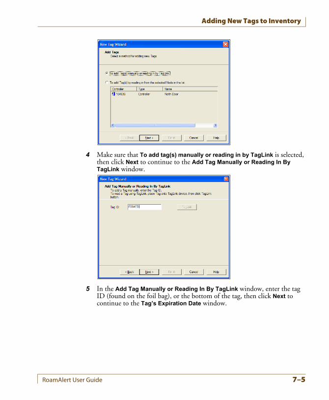
Adding New Tags to Inventory
4 Make sure that To add tag(s) manually or reading in by TagLink is selected, then click Next to continue to the Add Tag Manually or Reading In By TagLink window.
5 In the Add Tag Manually or Reading In By TagLink window, enter the tag ID (found on the foil bag), or the bottom of the tag, then click Next to continue to the Tag’s Expiration Date window.
RoamAlert User Guide 7–5
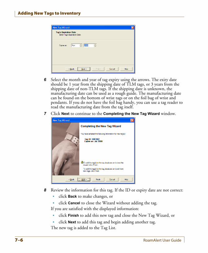
Adding New Tags to Inventory
6 Select the month and year of tag expiry using the arrows. The exiry date should be 1 year from the shipping date of TLM tags, or 3 years from the shipping date of non-TLM tags. If the shipping date is unknown, the manufacturing date can be used as a rough guide. The manufacturing date can be found on the bottom of wrist tags or on the foil bag of wrist and pendants. If you do not have the foil bag handy, you can use a tag reader to read the manufacturing date from the tag itself.
7 Click Next to continue to the Completing the New Tag Wizard window.
8 Review the information for this tag. If the ID or expiry date are not correct:• click Back to make changes, or
• click Cancel to close the Wizard without adding the tag.If you are satisfied with the displayed information:
• click Finish to add this new tag and close the New Tag Wizard, or
• click Next to add this tag and begin adding another tag.The new tag is added to the Tag List.
7–6 RoamAlert User Guide
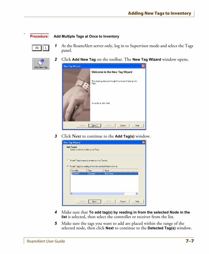
Adding New Tags to Inventory
Procedure: Add Multiple Tags at Once to Inventory
1 At the RoamAlert server only, log in to Supervisor mode and select the Tags panel.
2 Click Add New Tag on the toolbar. The New Tag Wizard window opens.
3 Click Next to continue to the Add Tag(s) window.
4 Make sure that To add tag(s) by reading in from the selected Node in the list is selected, then select the controller or receiver from the list.
5 Make sure the tags you want to add are placed within the range of the selected node, then click Next to continue to the Detected Tag(s) window.
RoamAlert User Guide 7–7
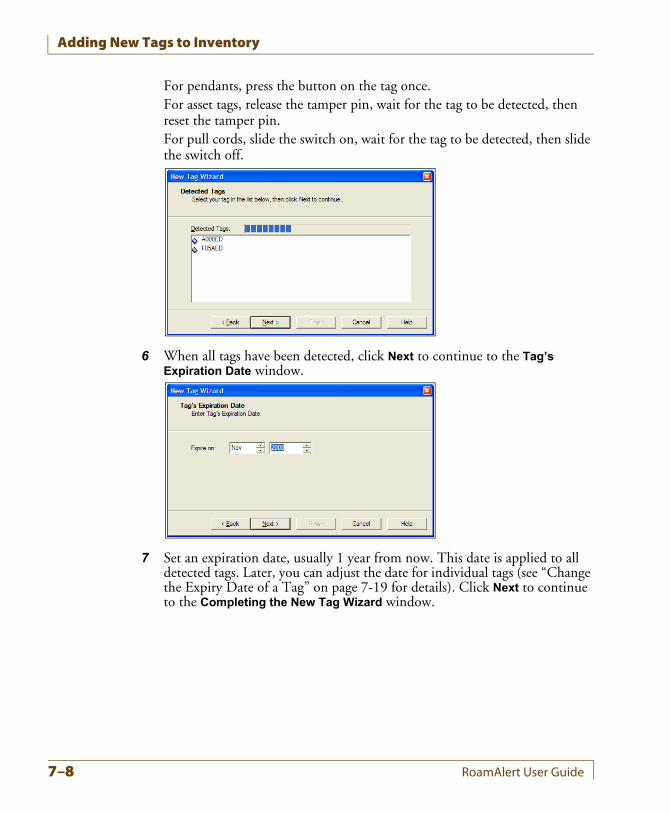
Adding New Tags to Inventory
For pendants, press the button on the tag once.For asset tags, release the tamper pin, wait for the tag to be detected, then reset the tamper pin.For pull cords, slide the switch on, wait for the tag to be detected, then slide the switch off.
6 When all tags have been detected, click Next to continue to the Tag’s Expiration Date window.
7 Set an expiration date, usually 1 year from now. This date is applied to all detected tags. Later, you can adjust the date for individual tags (see “Change the Expiry Date of a Tag” on page 7-19 for details). Click Next to continue to the Completing the New Tag Wizard window.
7–8 RoamAlert User Guide
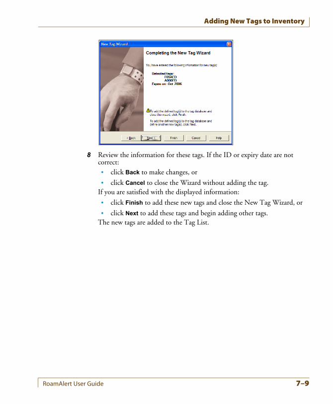
Adding New Tags to Inventory
8 Review the information for these tags. If the ID or expiry date are not correct:• click Back to make changes, or
• click Cancel to close the Wizard without adding the tag.If you are satisfied with the displayed information:
• click Finish to add these new tags and close the New Tag Wizard, or
• click Next to add these tags and begin adding other tags.The new tags are added to the Tag List.
RoamAlert User Guide 7–9
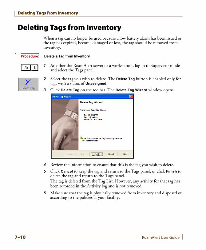
Deleting Tags from Inventory
Deleting Tags from InventoryWhen a tag can no longer be used because a low battery alarm has been issued or the tag has expired, become damaged or lost, the tag should be removed from inventory.
Procedure: Delete a Tag from Inventory
1 At either the RoamAlert server or a workstation, log in to Supervisor mode and select the Tags panel.
2 Select the tag you wish to delete. The Delete Tag button is enabled only for tags with a status of Unassigned.
3 Click Delete Tag on the toolbar. The Delete Tag Wizard window opens.
4 Review the information to ensure that this is the tag you wish to delete.
5 Click Cancel to keep the tag and return to the Tags panel, or click Finish to delete the tag and return to the Tags panel.The tag is deleted from the Tag List. However, any activity for that tag has been recorded in the Activity log and is not removed.
6 Make sure that the tag is physically removed from inventory and disposed of according to the policies at your facility.
7–10 RoamAlert User Guide
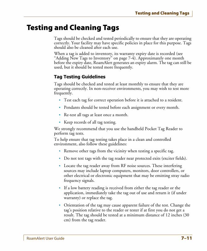
Testing and Cleaning Tags
Testing and Cleaning TagsTags should be checked and tested periodically to ensure that they are operating correctly. Your facility may have specific policies in place for this purpose. Tags should also be cleaned after each use.When a tag is added to inventory, its warranty expiry date is recorded (see “Adding New Tags to Inventory” on page 7-4). Approximately one month before the expiry date, RoamAlert generates an expiry alarm. The tag can still be used, but it should be tested more frequently.
Tag Testing GuidelinesTags should be checked and tested at least monthly to ensure that they are operating correctly. In non-receiver environments, you may wish to test more frequently.
• Test each tag for correct operation before it is attached to a resident.
• Pendants should be tested before each assignment or every month.
• Re-test all tags at least once a month.
• Keep records of all tag testing.
We strongly recommend that you use the handheld Pocket Tag Reader to perform tag tests.To help ensure that tag testing takes place in a clean and controlled environment, also follow these guidelines:
• Remove other tags from the vicinity when testing a specific tag.
• Do not test tags with the tag reader near protected exits (exciter fields).
• Locate the tag reader away from RF noise sources. These interfering sources may include laptop computers, monitors, door controllers, or other electrical or electronic equipment that may be emitting stray radio frequency signals.
• If a low battery reading is received from either the tag reader or the application, immediately take the tag out of use and return it (if under warranty) or replace the tag.
• Orientation of the tag may cause apparent failure of the test. Change the tag’s position relative to the reader or tester if at first you do not get a result. The tag should be tested at a minimum distance of 12 inches (30 cm) from the tag reader.
RoamAlert User Guide 7–11
Testing and Cleaning Tags
Procedure: How to Test a Tag With the Tag Reader
Follow these steps to test a tag:
1 Bring the tag reader and the tag into an environment as free of RF noise as possible.
2 Make sure only the tag being tested is in the vicinity of the tag reader.
3 Press and hold the ACCEPT (ON) button for a second or two to turn the tag reader on.
4 Press the UP button once to navigate to TAG TEST MODE.
5 Hold the tag at least 12 inches (30 cm) from the reader. For asset tags, make sure the tamper pin is depressed; for other tags, hold your thumb on the bottom of the tag if the tag is not on the resident or patient.
6 Press the ACCEPT button to begin the test. The tag reader reads the tag and displays its serial number and the message “TAG OK!”. The test is complete. Proceed to Step 9.
7 If, after about 20 seconds, the message “NO TAG DETECTED” is displayed, press ACCEPT again and then rotate the tag in relation to the tag reader. Keep the tag at least 12 inches (30 cm) from the reader.
8 If the message “NO TAG DETECTED” is displayed again, set the tag aside and do not use it. Return it if under warranty or replace it if not.
9 Record the test, including at a minimum the test date, tag serial # or resident name, and result (see Appendix B).
Procedure: How to Test a Tag at a Door or Protected Exit
If you do not have a tag reader or tester available, follow these steps to test a tag at a door or protected exit:
1 Take the resident, patient or the tag itself to a protected exit.
2 Ensure that the tag is detected according to the configuration of the controller, e.g. the door locks or the alarm sounds.
3 Record the test, including at a minimum the test date, tag serial # or resident name, and result (see Appendix B).
Cleaning the Tags• Tags are incompatible with disinfectants containing Glycol Ether.
• Tag straps are single-use. Do not clean or re-use. Upon discharge, cut them with scissors and discard.
7–12 RoamAlert User Guide
Testing and Cleaning Tags
Procedure: Clean Wrist Tags
1 Use a mild soap and water to remove any apparent debris.
2 Disinfect tags by wiping with an alcohol sanitizer or germicidal cleaner for no more than 60 seconds.
3 Dry with a soft, clean cloth.
4 Check the tag visually for physical damage.
Important: Do not autoclave tags.
RoamAlert User Guide 7–13
About Pendants
About PendantsA pendant can issue three different signals:
• Tag In Field (TIF) – when the tag enters a controller’s exciter field,
• Tag Location Message (TLM) – continuously at 16-second intervals,
• Tag Initiated Communication (TIC) – when the tag button is pressed.
A pendant is used to provide a controller bypass function for staff members. The tag can also be used to provide emergency call and location functions for staff and residents.The controller will lock the door or issue an alarm if the tag approaches the field unless the category associated with the tag allows free access to that controller, in which case the tag is invisible to that controller, and can pass without causing an alarm.If you want to provide wander prevention to a resident who also requires emergency call, the resident must be assigned a wrist tag as well. If the resident is free to enter and exit the facility, only the pendant is required.
7–14 RoamAlert User Guide
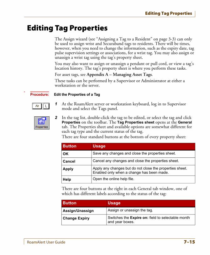
Editing Tag Properties
Editing Tag PropertiesThe Assign wizard (see “Assigning a Tag to a Resident” on page 3-3) can only be used to assign wrist and Securaband tags to residents. There will be times, however, when you need to change the information, such as the expiry date, tag pulse supervision settings or associations, for a wrist tag. You may also assign or unassign a wrist tag using the tag’s property sheet.You may also want to assign or unassign a pendant or pull cord, or view a tag’s location history. The tag’s property sheet is where you perform these tasks.For asset tags, see Appendix A – Managing Asset Tags.These tasks can be performed by a Supervisor or Administrator at either a workstation or the server.
Procedure: Edit the Properties of a Tag
1 At the RoamAlert server or workstation keyboard, log in to Supervisor mode and select the Tags panel.
2 In the tag list, double-click the tag to be edited, or select the tag and click Properties on the toolbar. The Tag Properties sheet opens at the General tab. The Properties sheet and available options are somewhat different for each tag type and the current status of the tag.There are four standard buttons at the bottom of every property sheet:
There are four buttons at the right in each General tab window, one of which has different labels according to the status of the tag:
Button Usage
OK Save any changes and close the properties sheet.
Cancel Cancel any changes and close the properties sheet.
Apply Apply any changes but do not close the properties sheet. Enabled only when a change has been made.
Help Open the online help file.
Button Usage
Assign/Unassign Assign or unassign the tag.
Change Expiry Switches the Expire on: field to selectable month and year boxes.
RoamAlert User Guide 7–15
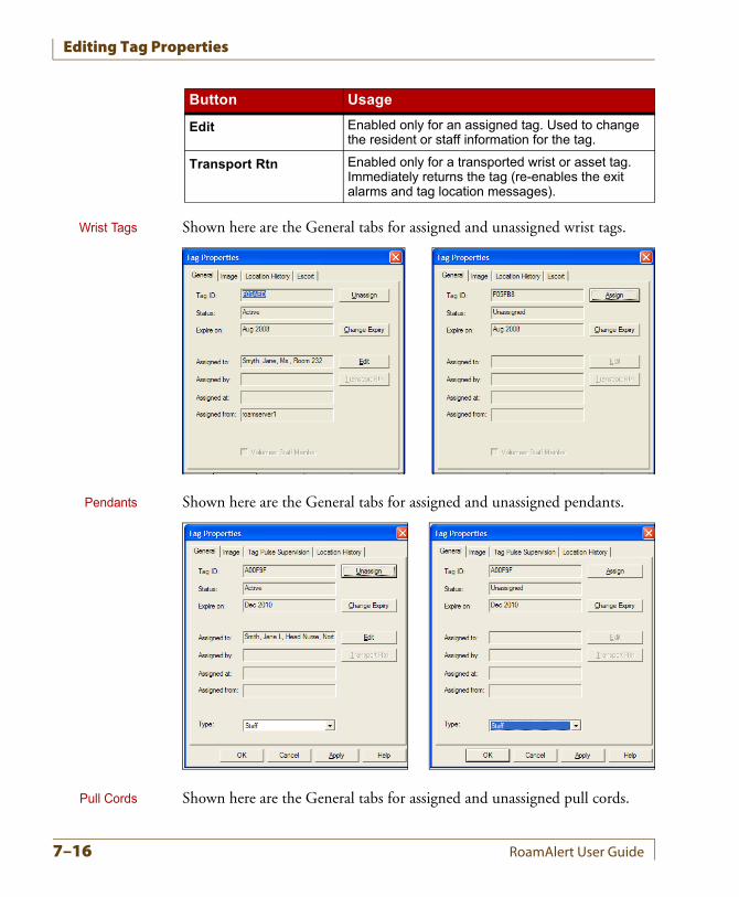
Editing Tag Properties
Wrist Tags Shown here are the General tabs for assigned and unassigned wrist tags.
Pendants Shown here are the General tabs for assigned and unassigned pendants.
Pull Cords Shown here are the General tabs for assigned and unassigned pull cords.
Edit Enabled only for an assigned tag. Used to change the resident or staff information for the tag.
Transport Rtn Enabled only for a transported wrist or asset tag. Immediately returns the tag (re-enables the exit alarms and tag location messages).
Button Usage
7–16 RoamAlert User Guide
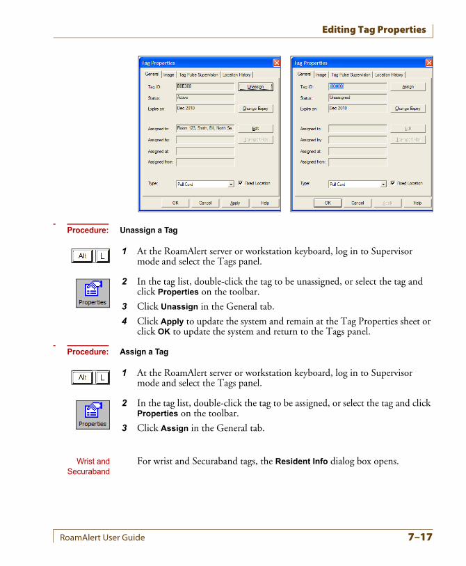
Editing Tag Properties
Procedure: Unassign a Tag
1 At the RoamAlert server or workstation keyboard, log in to Supervisor mode and select the Tags panel.
2 In the tag list, double-click the tag to be unassigned, or select the tag and click Properties on the toolbar.
3 Click Unassign in the General tab.
4 Click Apply to update the system and remain at the Tag Properties sheet or click OK to update the system and return to the Tags panel.
Procedure: Assign a Tag
1 At the RoamAlert server or workstation keyboard, log in to Supervisor mode and select the Tags panel.
2 In the tag list, double-click the tag to be assigned, or select the tag and click Properties on the toolbar.
3 Click Assign in the General tab.
Wrist andSecuraband
For wrist and Securaband tags, the Resident Info dialog box opens.
RoamAlert User Guide 7–17
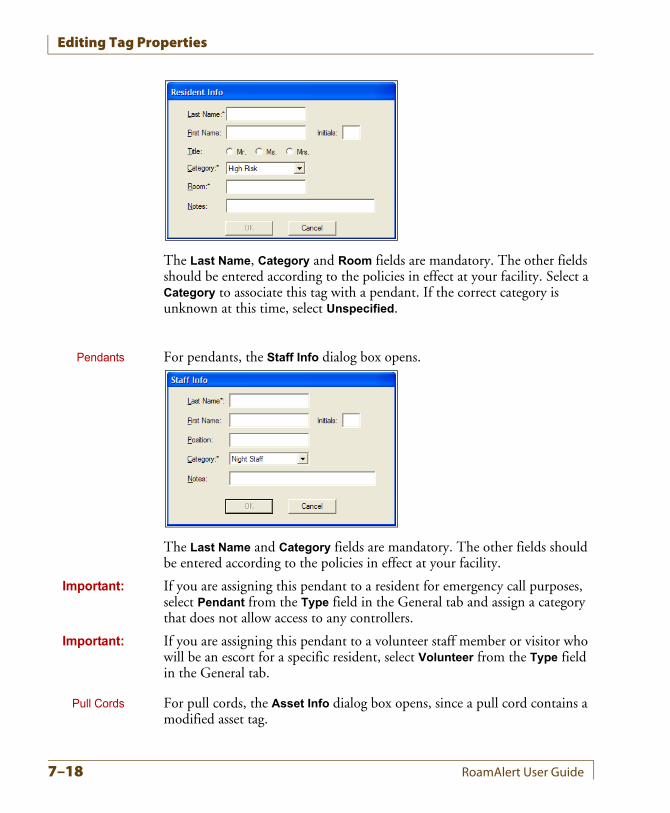
Editing Tag Properties
The Last Name, Category and Room fields are mandatory. The other fields should be entered according to the policies in effect at your facility. Select a Category to associate this tag with a pendant. If the correct category is unknown at this time, select Unspecified.
Pendants For pendants, the Staff Info dialog box opens.
The Last Name and Category fields are mandatory. The other fields should be entered according to the policies in effect at your facility.
Important: If you are assigning this pendant to a resident for emergency call purposes, select Pendant from the Type field in the General tab and assign a category that does not allow access to any controllers.
Important: If you are assigning this pendant to a volunteer staff member or visitor who will be an escort for a specific resident, select Volunteer from the Type field in the General tab.
Pull Cords For pull cords, the Asset Info dialog box opens, since a pull cord contains a modified asset tag.
7–18 RoamAlert User Guide
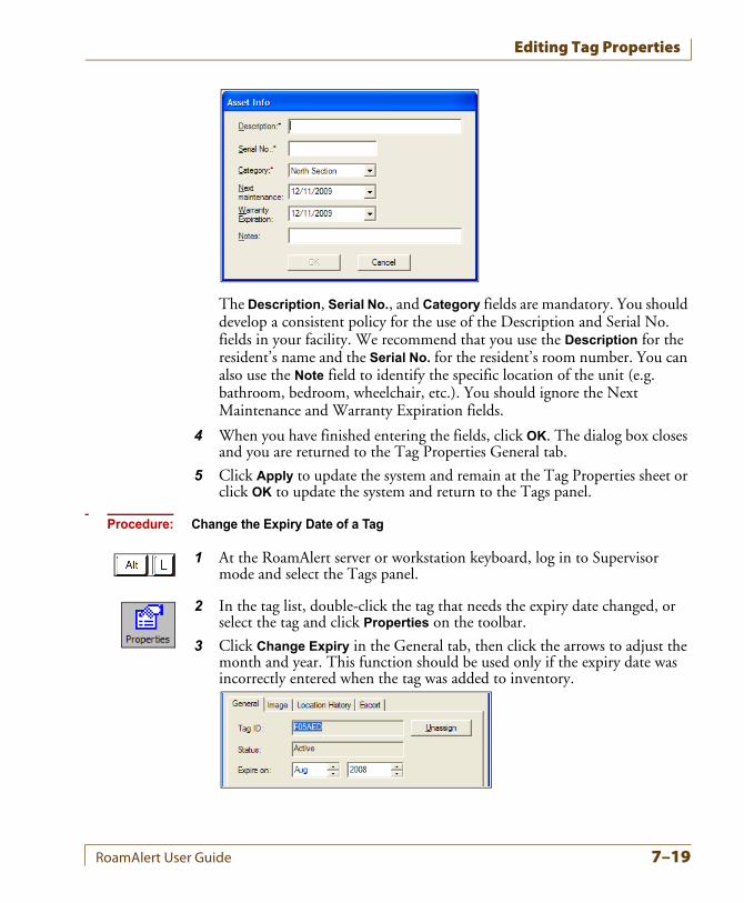
Editing Tag Properties
The Description, Serial No., and Category fields are mandatory. You should develop a consistent policy for the use of the Description and Serial No. fields in your facility. We recommend that you use the Description for the resident’s name and the Serial No. for the resident’s room number. You can also use the Note field to identify the specific location of the unit (e.g. bathroom, bedroom, wheelchair, etc.). You should ignore the Next Maintenance and Warranty Expiration fields.
4 When you have finished entering the fields, click OK. The dialog box closes and you are returned to the Tag Properties General tab.
5 Click Apply to update the system and remain at the Tag Properties sheet or click OK to update the system and return to the Tags panel.
Procedure: Change the Expiry Date of a Tag
1 At the RoamAlert server or workstation keyboard, log in to Supervisor mode and select the Tags panel.
2 In the tag list, double-click the tag that needs the expiry date changed, or select the tag and click Properties on the toolbar.
3 Click Change Expiry in the General tab, then click the arrows to adjust the month and year. This function should be used only if the expiry date was incorrectly entered when the tag was added to inventory.
RoamAlert User Guide 7–19
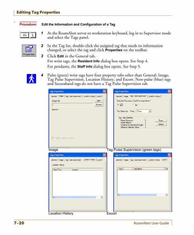
Editing Tag Properties
Procedure: Edit the Information and Configuration of a Tag
1 At the RoamAlert server or workstation keyboard, log in to Supervisor mode and select the Tags panel.
2 In the Tag list, double-click the assigned tag that needs its information changed, or select the tag and click Properties on the toolbar.
3 Click Edit in the General tab.For wrist tags, the Resident Info dialog box opens. See Step 4.For pendants, the Staff Info dialog box opens. See Step 5.
4 Pulse (green) wrist tags have four property tabs other than General: Image, Tag Pulse Supervision, Location History, and Escort. Non-pulse (blue) tags and Securaband tags do not have a Tag Pulse Supervision tab.
Image Tag Pulse Supervision (green tags)
Location History Escort
7–20 RoamAlert User Guide
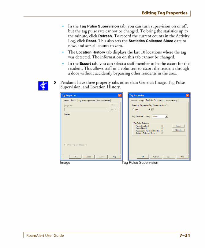
Editing Tag Properties
• In the Tag Pulse Supervision tab, you can turn supervision on or off, but the tag pulse rate cannot be changed. To bring the statistics up to the minute, click Refresh. To record the current counts in the Activity Log, click Reset. This also sets the Statistics Collected Since date to now, and sets all counts to zero.
• The Location History tab displays the last 10 locations where the tag was detected. The information on this tab cannot be changed.
• In the Escort tab, you can select a staff member to be the escort for the resident. This allows staff or a volunteer to escort the resident through a door without accidently bypassing other residents in the area.
5 Pendants have three property tabs other than General: Image, Tag Pulse Supervision, and Location History.
Image Tag Pulse Supervision
RoamAlert User Guide 7–21
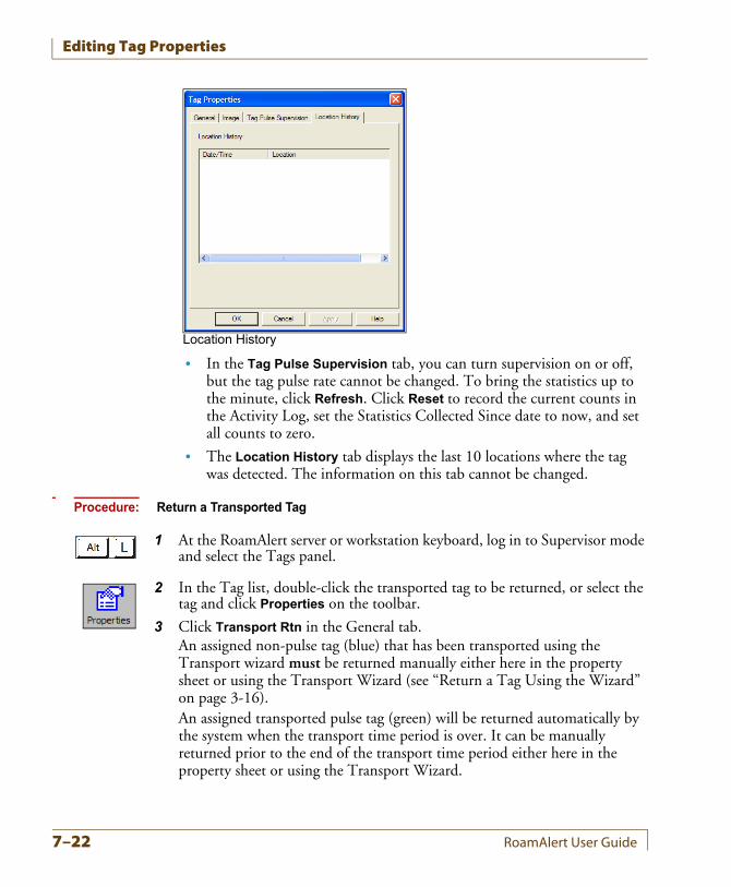
Editing Tag Properties
• In the Tag Pulse Supervision tab, you can turn supervision on or off, but the tag pulse rate cannot be changed. To bring the statistics up to the minute, click Refresh. Click Reset to record the current counts in the Activity Log, set the Statistics Collected Since date to now, and set all counts to zero.
• The Location History tab displays the last 10 locations where the tag was detected. The information on this tab cannot be changed.
Procedure: Return a Transported Tag
1 At the RoamAlert server or workstation keyboard, log in to Supervisor mode and select the Tags panel.
2 In the Tag list, double-click the transported tag to be returned, or select the tag and click Properties on the toolbar.
3 Click Transport Rtn in the General tab.An assigned non-pulse tag (blue) that has been transported using the Transport wizard must be returned manually either here in the property sheet or using the Transport Wizard (see “Return a Tag Using the Wizard” on page 3-16).An assigned transported pulse tag (green) will be returned automatically by the system when the transport time period is over. It can be manually returned prior to the end of the transport time period either here in the property sheet or using the Transport Wizard.
Location History
7–22 RoamAlert User Guide
Chapter 8CHAPTER 0ROAMALERT SYSTEM
CONFIGURATION
RoamAlert system configuration procedures include:
• Defining and managing alarm annotations
• Defining and managing tag categories
• Configuring and managing messaging devices (pagers, etc.)
• Specifying global software settings
• Managing alarm sound configurations
• Managing floor plans and floor plan icons
• Configuring and managing workstations
Supervisors can only perform alarm annotation, tag category and messaging device procedures. The remaining software configuration procedures must be carried out by an Administrator.Supervisor mode procedures may be carried out at the server or a workstation. Administrator mode procedures must be carried out at the server.
RoamAlert User Guide 8–1
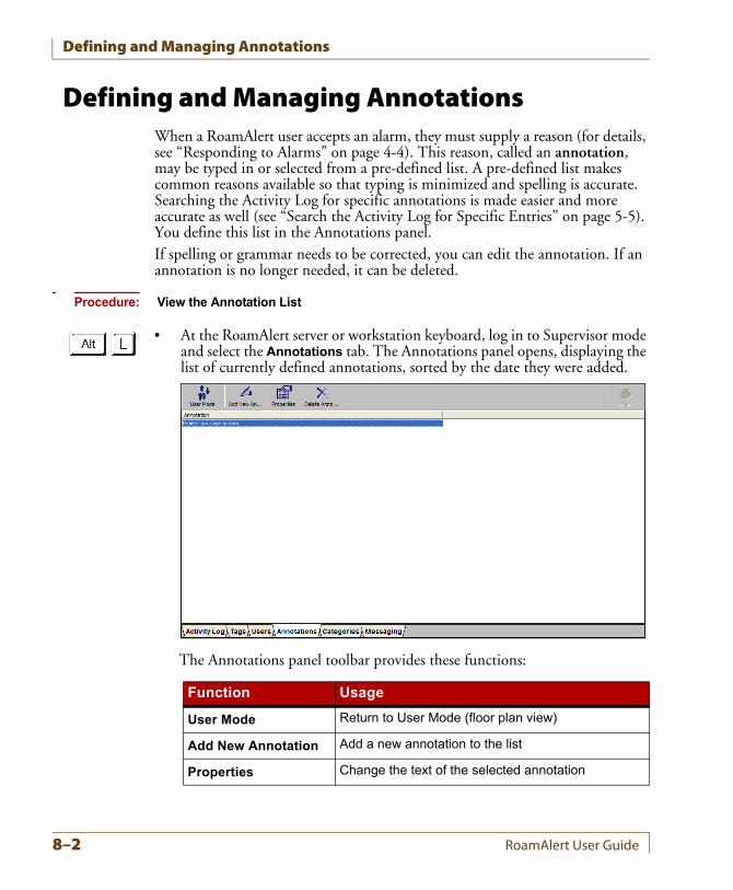
Defining and Managing Annotations
Defining and Managing AnnotationsWhen a RoamAlert user accepts an alarm, they must supply a reason (for details, see “Responding to Alarms” on page 4-4). This reason, called an annotation, may be typed in or selected from a pre-defined list. A pre-defined list makes common reasons available so that typing is minimized and spelling is accurate. Searching the Activity Log for specific annotations is made easier and more accurate as well (see “Search the Activity Log for Specific Entries” on page 5-5). You define this list in the Annotations panel.If spelling or grammar needs to be corrected, you can edit the annotation. If an annotation is no longer needed, it can be deleted.
Procedure: View the Annotation List
• At the RoamAlert server or workstation keyboard, log in to Supervisor mode and select the Annotations tab. The Annotations panel opens, displaying the list of currently defined annotations, sorted by the date they were added.
The Annotations panel toolbar provides these functions:
Function Usage
User Mode Return to User Mode (floor plan view)
Add New Annotation Add a new annotation to the list
Properties Change the text of the selected annotation
8–2 RoamAlert User Guide
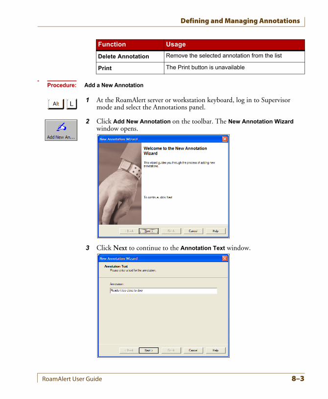
Defining and Managing Annotations
Procedure: Add a New Annotation
1 At the RoamAlert server or workstation keyboard, log in to Supervisor mode and select the Annotations panel.
2 Click Add New Annotation on the toolbar. The New Annotation Wizard window opens.
3 Click Next to continue to the Annotation Text window.
Delete Annotation Remove the selected annotation from the list
Print The Print button is unavailable
Function Usage
RoamAlert User Guide 8–3
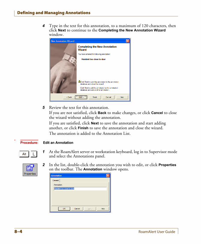
Defining and Managing Annotations
4 Type in the text for this annotation, to a maximum of 120 characters, then click Next to continue to the Completing the New Annotation Wizard window.
5 Review the text for this annotation.If you are not satisfied, click Back to make changes, or click Cancel to close the wizard without adding the annotation.If you are satisfied, click Next to save the annotation and start adding another, or click Finish to save the annotation and close the wizard.The annotation is added to the Annotation List.
Procedure: Edit an Annotation
1 At the RoamAlert server or workstation keyboard, log in to Supervisor mode and select the Annotations panel.
2 In the list, double-click the annotation you wish to edit, or click Properties on the toolbar. The Annotation window opens.
8–4 RoamAlert User Guide
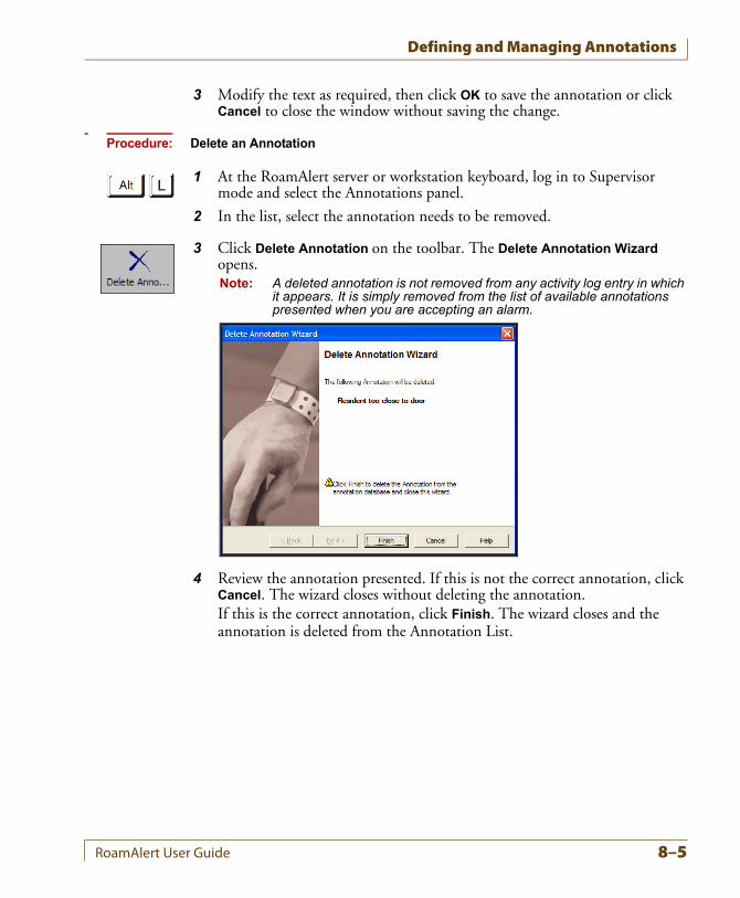
Defining and Managing Annotations
3 Modify the text as required, then click OK to save the annotation or click Cancel to close the window without saving the change.
Procedure: Delete an Annotation
1 At the RoamAlert server or workstation keyboard, log in to Supervisor mode and select the Annotations panel.
2 In the list, select the annotation needs to be removed.
3 Click Delete Annotation on the toolbar. The Delete Annotation Wizard opens.Note: A deleted annotation is not removed from any activity log entry in which
it appears. It is simply removed from the list of available annotations presented when you are accepting an alarm.
4 Review the annotation presented. If this is not the correct annotation, click Cancel. The wizard closes without deleting the annotation.If this is the correct annotation, click Finish. The wizard closes and the annotation is deleted from the Annotation List.
RoamAlert User Guide 8–5
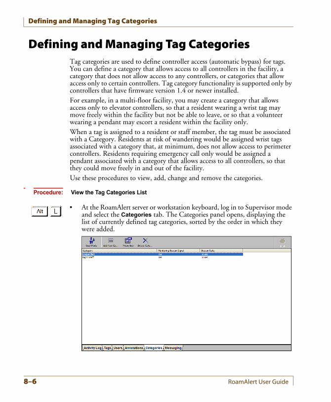
Defining and Managing Tag Categories
Defining and Managing Tag CategoriesTag categories are used to define controller access (automatic bypass) for tags. You can define a category that allows access to all controllers in the facility, a category that does not allow access to any controllers, or categories that allow access only to certain controllers. Tag category functionality is supported only by controllers that have firmware version 1.4 or newer installed.For example, in a multi-floor facility, you may create a category that allows access only to elevator controllers, so that a resident wearing a wrist tag may move freely within the facility but not be able to leave, or so that a volunteer wearing a pendant may escort a resident within the facility only.When a tag is assigned to a resident or staff member, the tag must be associated with a Category. Residents at risk of wandering would be assigned wrist tags associated with a category that, at minimum, does not allow access to perimeter controllers. Residents requiring emergency call only would be assigned a pendant associated with a category that allows access to all controllers, so that they could move freely in and out of the facility.Use these procedures to view, add, change and remove the categories.
Procedure: View the Tag Categories List
• At the RoamAlert server or workstation keyboard, log in to Supervisor mode and select the Categories tab. The Categories panel opens, displaying the list of currently defined tag categories, sorted by the order in which they were added.
8–6 RoamAlert User Guide
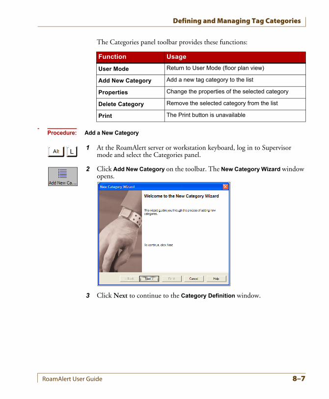
Defining and Managing Tag Categories
The Categories panel toolbar provides these functions:
Procedure: Add a New Category
1 At the RoamAlert server or workstation keyboard, log in to Supervisor mode and select the Categories panel.
2 Click Add New Category on the toolbar. The New Category Wizard window opens.
3 Click Next to continue to the Category Definition window.
Function Usage
User Mode Return to User Mode (floor plan view)
Add New Category Add a new tag category to the list
Properties Change the properties of the selected category
Delete Category Remove the selected category from the list
Print The Print button is unavailable
RoamAlert User Guide 8–7
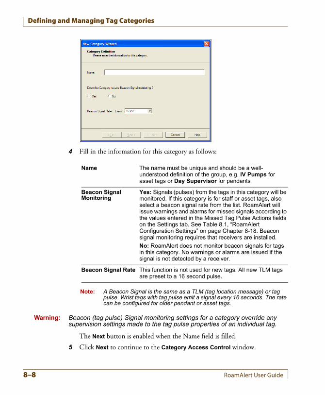
Defining and Managing Tag Categories
4 Fill in the information for this category as follows:
Note: A Beacon Signal is the same as a TLM (tag location message) or tag pulse. Wrist tags with tag pulse emit a signal every 16 seconds. The rate can be configured for older pendant or asset tags.
Warning: Beacon (tag pulse) Signal monitoring settings for a category override any supervision settings made to the tag pulse properties of an individual tag.
The Next button is enabled when the Name field is filled.
5 Click Next to continue to the Category Access Control window.
Name The name must be unique and should be a well-understood definition of the group, e.g. IV Pumps for asset tags or Day Supervisor for pendants
Beacon Signal Monitoring
Yes: Signals (pulses) from the tags in this category will be monitored. If this category is for staff or asset tags, also select a beacon signal rate from the list. RoamAlert will issue warnings and alarms for missed signals according to the values entered in the Missed Tag Pulse Actions fields on the Settings tab. See Table 8.1, “RoamAlert Configuration Settings” on page Chapter 8-18. Beacon signal monitoring requires that receivers are installed.
No: RoamAlert does not monitor beacon signals for tags in this category. No warnings or alarms are issued if the signal is not detected by a receiver.
Beacon Signal Rate This function is not used for new tags. All new TLM tags are preset to a 16 second pulse.
8–8 RoamAlert User Guide
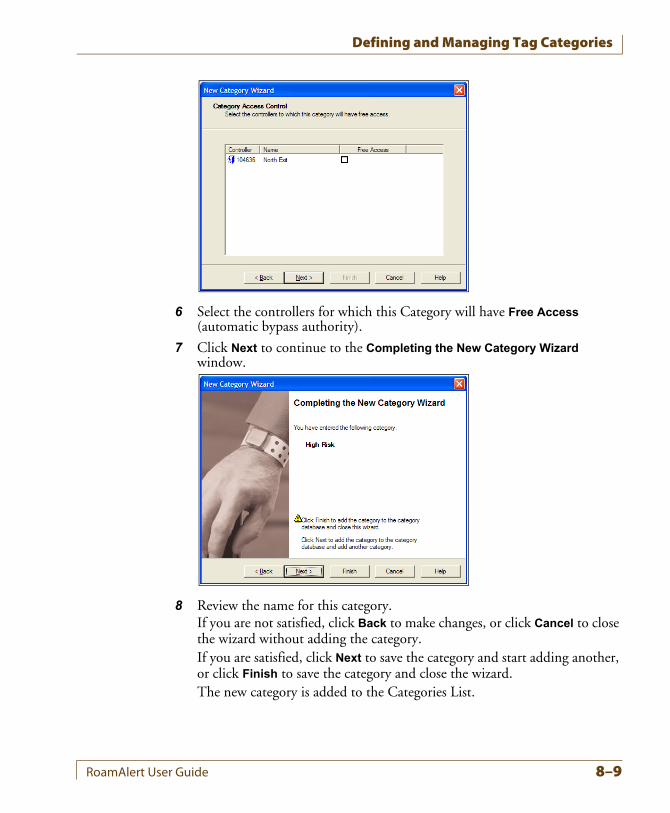
Defining and Managing Tag Categories
6 Select the controllers for which this Category will have Free Access (automatic bypass authority).
7 Click Next to continue to the Completing the New Category Wizard window.
8 Review the name for this category.If you are not satisfied, click Back to make changes, or click Cancel to close the wizard without adding the category.If you are satisfied, click Next to save the category and start adding another, or click Finish to save the category and close the wizard.The new category is added to the Categories List.
RoamAlert User Guide 8–9
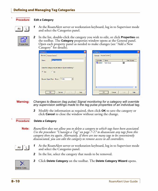
Defining and Managing Tag Categories
Procedure: Edit a Category
1 At the RoamAlert server or workstation keyboard, log in to Supervisor mode and select the Categories panel.
2 In the list, double-click the category you wish to edit, or click Properties on the toolbar. The Category properties window opens at the General panel. Open each property panel as needed to make changes (see “Add a New Category” for details).
Warning: Changes to Beacon (tag pulse) Signal monitoring for a category will override any supervision settings made to the tag pulse properties of an individual tag.
3 Modify the information as required, then click OK to save the category or click Cancel to close the window without saving the change.
Procedure: Delete a Category
Note: RoamAlert does not allow you to delete a category to which tags have been associated. Use the procedure “Unassign a Tag” on page 7-17 to disassociate any tags from this category then try again. Alternately, if there are too many tags to be conveniently disassociated, you can edit the category to remove access to all controllers.
1 At the RoamAlert server or workstation keyboard, log in to Supervisor mode and select the Categories panel.
2 In the list, select the category that needs to be removed.
3 Click Delete Category on the toolbar. The Delete Category Wizard opens.
8–10 RoamAlert User Guide
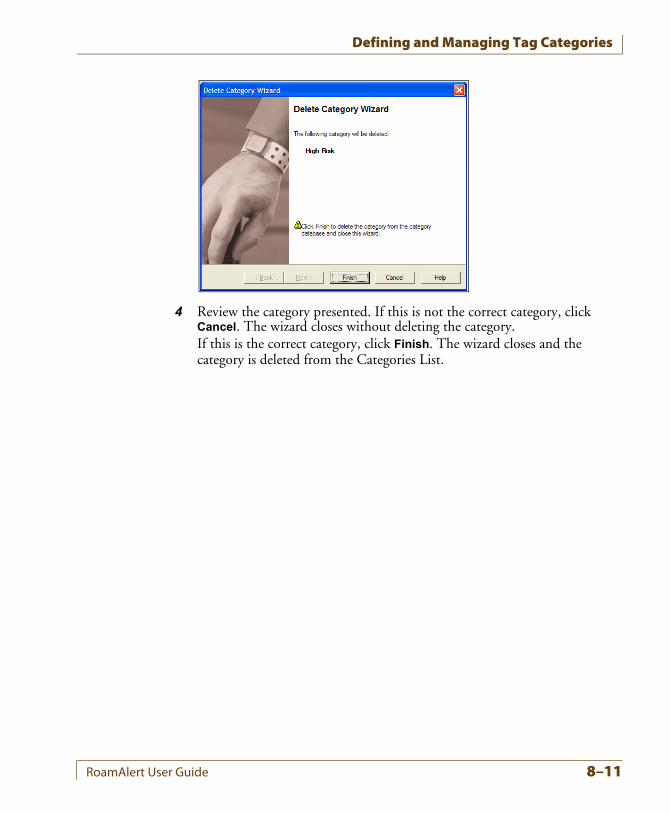
Defining and Managing Tag Categories
4 Review the category presented. If this is not the correct category, click Cancel. The wizard closes without deleting the category.If this is the correct category, click Finish. The wizard closes and the category is deleted from the Categories List.
RoamAlert User Guide 8–11
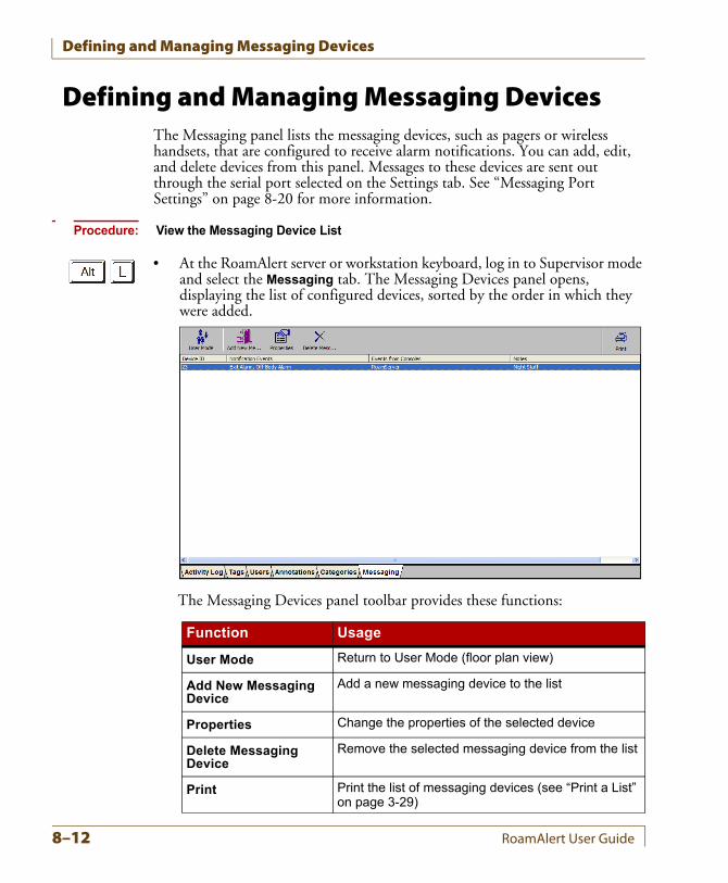
Defining and Managing Messaging Devices
Defining and Managing Messaging DevicesThe Messaging panel lists the messaging devices, such as pagers or wireless handsets, that are configured to receive alarm notifications. You can add, edit, and delete devices from this panel. Messages to these devices are sent out through the serial port selected on the Settings tab. See “Messaging Port Settings” on page 8-20 for more information.
Procedure: View the Messaging Device List
• At the RoamAlert server or workstation keyboard, log in to Supervisor mode and select the Messaging tab. The Messaging Devices panel opens, displaying the list of configured devices, sorted by the order in which they were added.
The Messaging Devices panel toolbar provides these functions:
Function Usage
User Mode Return to User Mode (floor plan view)
Add New Messaging Device
Add a new messaging device to the list
Properties Change the properties of the selected device
Delete Messaging Device
Remove the selected messaging device from the list
Print Print the list of messaging devices (see “Print a List” on page 3-29)
8–12 RoamAlert User Guide
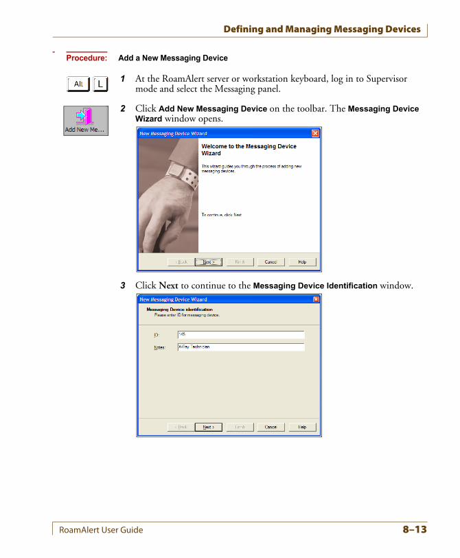
Defining and Managing Messaging Devices
Procedure: Add a New Messaging Device
1 At the RoamAlert server or workstation keyboard, log in to Supervisor mode and select the Messaging panel.
2 Click Add New Messaging Device on the toolbar. The Messaging Device Wizard window opens.
3 Click Next to continue to the Messaging Device Identification window.
RoamAlert User Guide 8–13
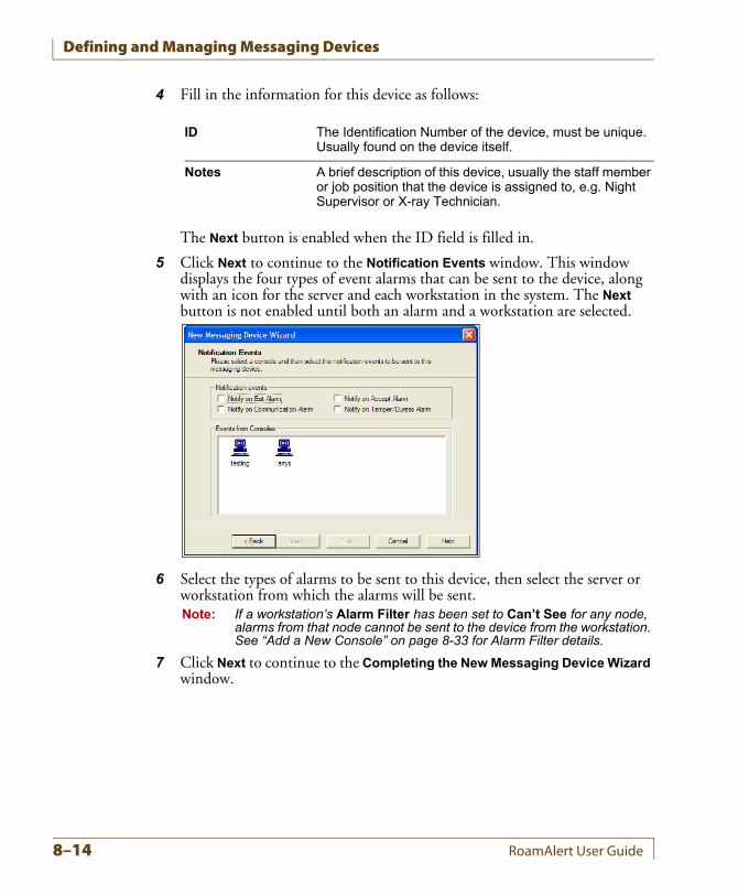
Defining and Managing Messaging Devices
4 Fill in the information for this device as follows:
The Next button is enabled when the ID field is filled in.
5 Click Next to continue to the Notification Events window. This window displays the four types of event alarms that can be sent to the device, along with an icon for the server and each workstation in the system. The Next button is not enabled until both an alarm and a workstation are selected.
6 Select the types of alarms to be sent to this device, then select the server or workstation from which the alarms will be sent.Note: If a workstation’s Alarm Filter has been set to Can’t See for any node,
alarms from that node cannot be sent to the device from the workstation. See “Add a New Console” on page 8-33 for Alarm Filter details.
7 Click Next to continue to the Completing the New Messaging Device Wizard window.
ID The Identification Number of the device, must be unique. Usually found on the device itself.
Notes A brief description of this device, usually the staff member or job position that the device is assigned to, e.g. Night Supervisor or X-ray Technician.
8–14 RoamAlert User Guide
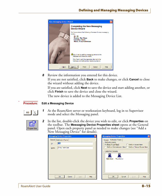
Defining and Managing Messaging Devices
8 Review the information you entered for this device.If you are not satisfied, click Back to make changes, or click Cancel to close the wizard without adding the device.If you are satisfied, click Next to save the device and start adding another, or click Finish to save the device and close the wizard.The new device is added to the Messaging Device List.
Procedure: Edit a Messaging Device
1 At the RoamAlert server or workstation keyboard, log in to Supervisor mode and select the Messaging panel.
2 In the list, double-click the device you wish to edit, or click Properties on the toolbar. The Messaging Device Properties sheet opens at the General panel. Open each property panel as needed to make changes (see “Add a New Messaging Device” for details).
RoamAlert User Guide 8–15
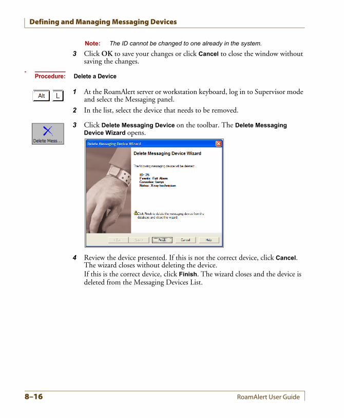
Defining and Managing Messaging Devices
Note: The ID cannot be changed to one already in the system.
3 Click OK to save your changes or click Cancel to close the window without saving the changes.
Procedure: Delete a Device
1 At the RoamAlert server or workstation keyboard, log in to Supervisor mode and select the Messaging panel.
2 In the list, select the device that needs to be removed.
3 Click Delete Messaging Device on the toolbar. The Delete Messaging Device Wizard opens.
4 Review the device presented. If this is not the correct device, click Cancel. The wizard closes without deleting the device.If this is the correct device, click Finish. The wizard closes and the device is deleted from the Messaging Devices List.
8–16 RoamAlert User Guide
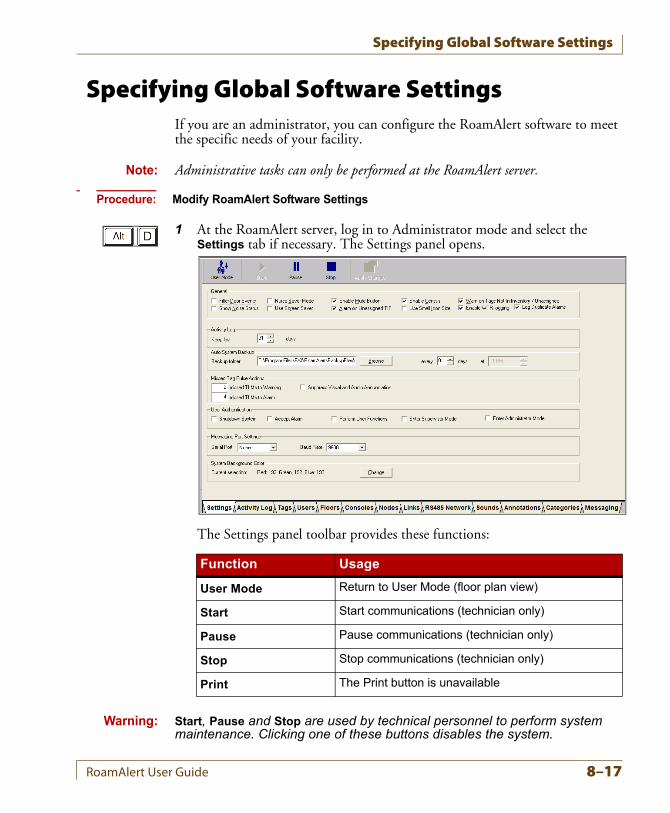
Specifying Global Software Settings
Specifying Global Software SettingsIf you are an administrator, you can configure the RoamAlert software to meet the specific needs of your facility.
Note: Administrative tasks can only be performed at the RoamAlert server.
Procedure: Modify RoamAlert Software Settings
1 At the RoamAlert server, log in to Administrator mode and select the Settings tab if necessary. The Settings panel opens.
The Settings panel toolbar provides these functions:
Warning: Start, Pause and Stop are used by technical personnel to perform system maintenance. Clicking one of these buttons disables the system.
Function Usage
User Mode Return to User Mode (floor plan view)
Start Start communications (technician only)
Pause Pause communications (technician only)
Stop Stop communications (technician only)
Print The Print button is unavailable
RoamAlert User Guide 8–17
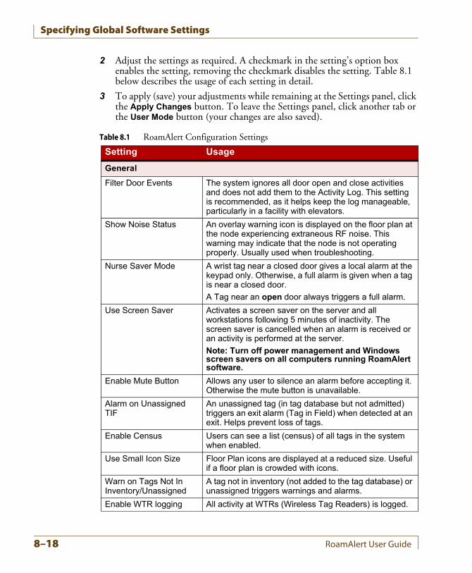
Specifying Global Software Settings
2 Adjust the settings as required. A checkmark in the setting’s option box enables the setting, removing the checkmark disables the setting. Table 8.1 below describes the usage of each setting in detail.
3 To apply (save) your adjustments while remaining at the Settings panel, click the Apply Changes button. To leave the Settings panel, click another tab or the User Mode button (your changes are also saved).
Table 8.1 RoamAlert Configuration Settings
Setting Usage
General
Filter Door Events The system ignores all door open and close activities and does not add them to the Activity Log. This setting is recommended, as it helps keep the log manageable, particularly in a facility with elevators.
Show Noise Status An overlay warning icon is displayed on the floor plan at the node experiencing extraneous RF noise. This warning may indicate that the node is not operating properly. Usually used when troubleshooting.
Nurse Saver Mode A wrist tag near a closed door gives a local alarm at the keypad only. Otherwise, a full alarm is given when a tag is near a closed door.
A Tag near an open door always triggers a full alarm.
Use Screen Saver Activates a screen saver on the server and all workstations following 5 minutes of inactivity. The screen saver is cancelled when an alarm is received or an activity is performed at the server.
Note: Turn off power management and Windows screen savers on all computers running RoamAlert software.
Enable Mute Button Allows any user to silence an alarm before accepting it. Otherwise the mute button is unavailable.
Alarm on Unassigned TIF
An unassigned tag (in tag database but not admitted) triggers an exit alarm (Tag in Field) when detected at an exit. Helps prevent loss of tags.
Enable Census Users can see a list (census) of all tags in the system when enabled.
Use Small Icon Size Floor Plan icons are displayed at a reduced size. Useful if a floor plan is crowded with icons.
Warn on Tags Not In Inventory/Unassigned
A tag not in inventory (not added to the tag database) or unassigned triggers warnings and alarms.
Enable WTR logging All activity at WTRs (Wireless Tag Readers) is logged.
8–18 RoamAlert User Guide
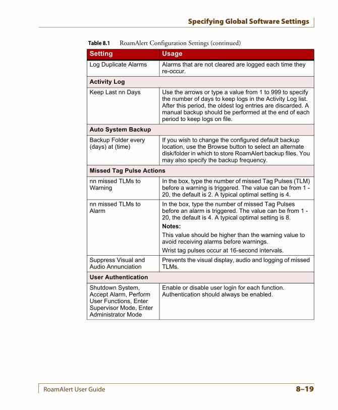
Specifying Global Software Settings
Log Duplicate Alarms Alarms that are not cleared are logged each time they re-occur.
Activity Log
Keep Last nn Days Use the arrows or type a value from 1 to 999 to specify the number of days to keep logs in the Activity Log list. After this period, the oldest log entries are discarded. A manual backup should be performed at the end of each period to keep logs on file.
Auto System Backup
Backup Folder every (days) at (time)
If you wish to change the configured default backup location, use the Browse button to select an alternate disk/folder in which to store RoamAlert backup files. You may also specify the backup frequency.
Missed Tag Pulse Actions
nn missed TLMs to Warning
In the box, type the number of missed Tag Pulses (TLM) before a warning is triggered. The value can be from 1 - 20, the default is 2. A typical optimal setting is 4.
nn missed TLMs to Alarm
In the box, type the number of missed Tag Pulses before an alarm is triggered. The value can be from 1 - 20, the default is 4. A typical optimal setting is 8.
Notes:
This value should be higher than the warning value to avoid receiving alarms before warnings.
Wrist tag pulses occur at 16-second intervals.
Suppress Visual and Audio Annunciation
Prevents the visual display, audio and logging of missed TLMs.
User Authentication
Shutdown System, Accept Alarm, Perform User Functions, Enter Supervisor Mode, Enter Administrator Mode
Enable or disable user login for each function. Authentication should always be enabled.
Table 8.1 RoamAlert Configuration Settings (continued)
Setting Usage
RoamAlert User Guide 8–19
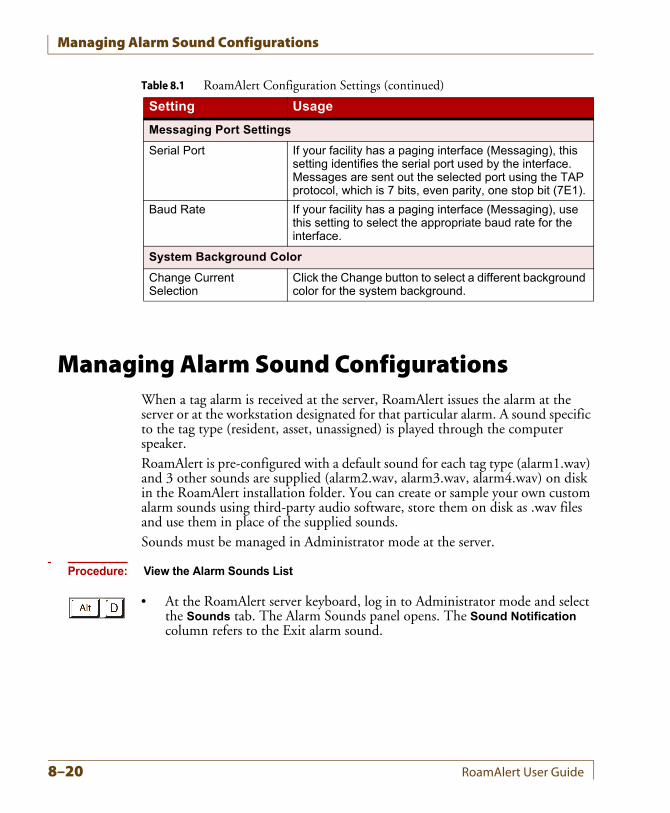
Managing Alarm Sound Configurations
Managing Alarm Sound ConfigurationsWhen a tag alarm is received at the server, RoamAlert issues the alarm at the server or at the workstation designated for that particular alarm. A sound specific to the tag type (resident, asset, unassigned) is played through the computer speaker.RoamAlert is pre-configured with a default sound for each tag type (alarm1.wav) and 3 other sounds are supplied (alarm2.wav, alarm3.wav, alarm4.wav) on disk in the RoamAlert installation folder. You can create or sample your own custom alarm sounds using third-party audio software, store them on disk as .wav files and use them in place of the supplied sounds.Sounds must be managed in Administrator mode at the server.
Procedure: View the Alarm Sounds List
• At the RoamAlert server keyboard, log in to Administrator mode and select the Sounds tab. The Alarm Sounds panel opens. The Sound Notification column refers to the Exit alarm sound.
Messaging Port Settings
Serial Port If your facility has a paging interface (Messaging), this setting identifies the serial port used by the interface. Messages are sent out the selected port using the TAP protocol, which is 7 bits, even parity, one stop bit (7E1).
Baud Rate If your facility has a paging interface (Messaging), use this setting to select the appropriate baud rate for the interface.
System Background Color
Change Current Selection
Click the Change button to select a different background color for the system background.
Table 8.1 RoamAlert Configuration Settings (continued)
Setting Usage
8–20 RoamAlert User Guide
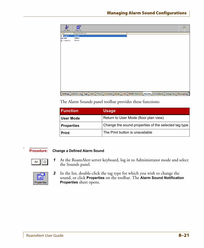
Managing Alarm Sound Configurations
The Alarm Sounds panel toolbar provides these functions:
Procedure: Change a Defined Alarm Sound
1 At the RoamAlert server keyboard, log in to Administrator mode and select the Sounds panel.
2 In the list, double-click the tag type for which you wish to change the sound, or click Properties on the toolbar. The Alarm Sound Notification Properties sheet opens.
Function Usage
User Mode Return to User Mode (floor plan view)
Properties Change the sound properties of the selected tag type
Print The Print button is unavailable
RoamAlert User Guide 8–21
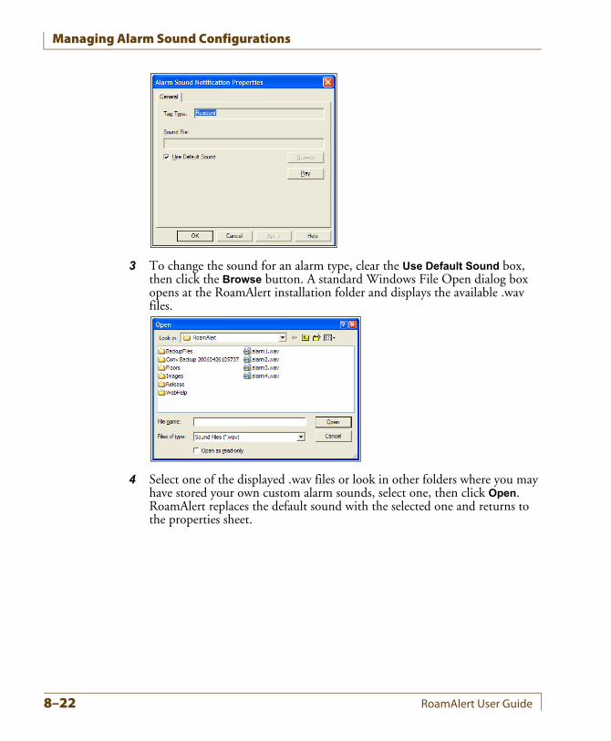
Managing Alarm Sound Configurations
3 To change the sound for an alarm type, clear the Use Default Sound box, then click the Browse button. A standard Windows File Open dialog box opens at the RoamAlert installation folder and displays the available .wav files.
4 Select one of the displayed .wav files or look in other folders where you may have stored your own custom alarm sounds, select one, then click Open. RoamAlert replaces the default sound with the selected one and returns to the properties sheet.
8–22 RoamAlert User Guide
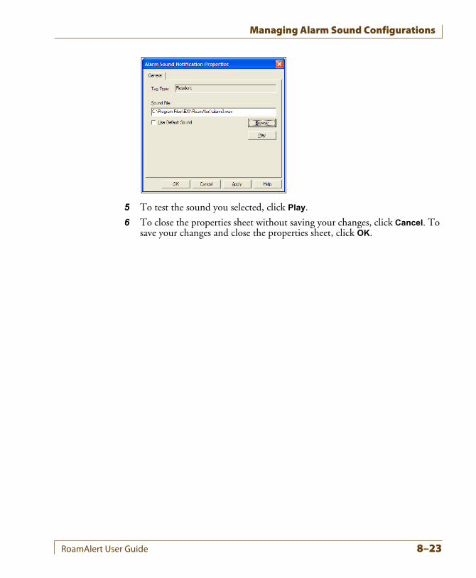
Managing Alarm Sound Configurations
5 To test the sound you selected, click Play.
6 To close the properties sheet without saving your changes, click Cancel. To save your changes and close the properties sheet, click OK.
RoamAlert User Guide 8–23
Managing Floor Plans and Floor Plan Icons
Managing Floor Plans and Floor Plan IconsIcons for each node (receivers, workstations, server, controllers, I/O 8 modules) are displayed on the floor plans in the exact location of the node in the facility. In a multi-floor facility, a set of tabs at the upper left of the floor plan area controls the display of floors. The leftmost tab displays the default floor, that is, the floor that is normally displayed when there is no alarm activity.In User mode, alarm activity is displayed on the floor plan at the node location closest to the alarm on the workstations set up to display alarms from that floor.In a multi-floor facility, the floor where an alarm occurs is immediately displayed no matter which floor is currently displayed. When the alarm is accepted, the display reverts to the default floor.Floor plans must be managed in Administrator mode at the server.
Procedure: View Floor Plans
• At the RoamAlert server keyboard, log in to Administrator mode and select the Floors tab. The Floors panel opens. If this is a multi-floor facility, you can display each floor using the name tabs at the upper left.Note: The floors displayed in this guide are strictly for demonstration purposes
and will not resemble the floors in your facility.
In a multi-floor facility, floors are displayed in tab order, left to right. Clicking any floor tab displays that floor for 2 minutes, after which the display reverts to the default floor.
8–24 RoamAlert User Guide
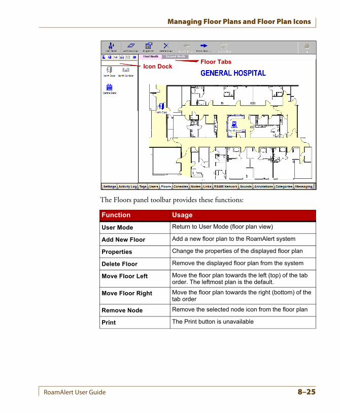
Managing Floor Plans and Floor Plan Icons
The Floors panel toolbar provides these functions:
Function Usage
User Mode Return to User Mode (floor plan view)
Add New Floor Add a new floor plan to the RoamAlert system
Properties Change the properties of the displayed floor plan
Delete Floor Remove the displayed floor plan from the system
Move Floor Left Move the floor plan towards the left (top) of the tab order. The leftmost plan is the default.
Move Floor Right Move the floor plan towards the right (bottom) of the tab order
Remove Node Remove the selected node icon from the floor plan
Print The Print button is unavailable
Icon DockFloor Tabs
RoamAlert User Guide 8–25
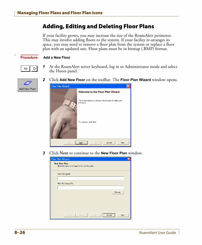
Managing Floor Plans and Floor Plan Icons
Adding, Editing and Deleting Floor PlansIf your facility grows, you may increase the size of the RoamAlert perimeter. This may involve adding floors to the system. If your facility re-arranges its space, you may need to remove a floor plan from the system or replace a floor plan with an updated one. Floor plans must be in bitmap (.BMP) format.
Procedure: Add a New Floor
1 At the RoamAlert server keyboard, log in to Administrator mode and select the Floors panel.
2 Click Add New Floor on the toolbar. The Floor Plan Wizard window opens.
3 Click Next to continue to the New Floor Plan window.
8–26 RoamAlert User Guide
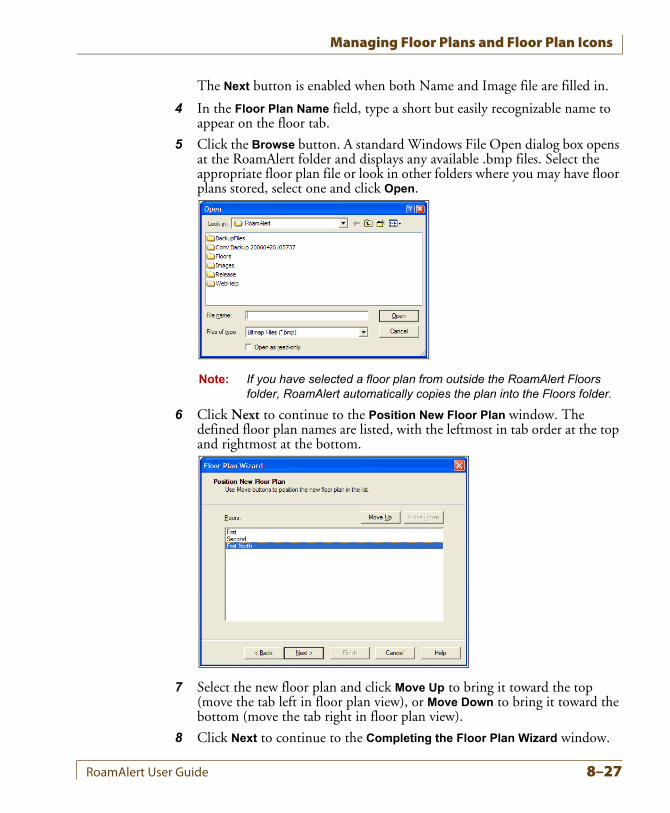
Managing Floor Plans and Floor Plan Icons
The Next button is enabled when both Name and Image file are filled in.
4 In the Floor Plan Name field, type a short but easily recognizable name to appear on the floor tab.
5 Click the Browse button. A standard Windows File Open dialog box opens at the RoamAlert folder and displays any available .bmp files. Select the appropriate floor plan file or look in other folders where you may have floor plans stored, select one and click Open.
Note: If you have selected a floor plan from outside the RoamAlert Floors folder, RoamAlert automatically copies the plan into the Floors folder.
6 Click Next to continue to the Position New Floor Plan window. The defined floor plan names are listed, with the leftmost in tab order at the top and rightmost at the bottom.
7 Select the new floor plan and click Move Up to bring it toward the top (move the tab left in floor plan view), or Move Down to bring it toward the bottom (move the tab right in floor plan view).
8 Click Next to continue to the Completing the Floor Plan Wizard window.
RoamAlert User Guide 8–27
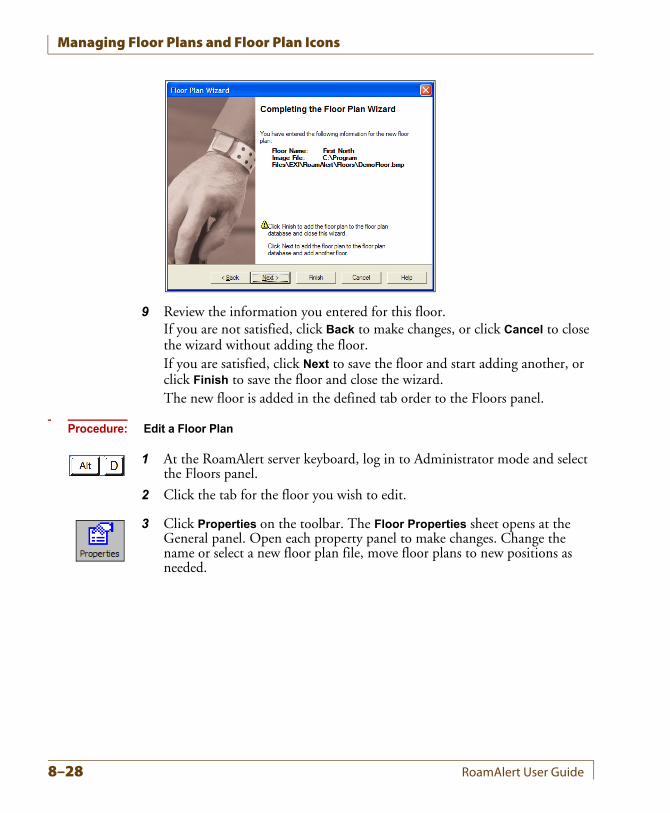
Managing Floor Plans and Floor Plan Icons
9 Review the information you entered for this floor.If you are not satisfied, click Back to make changes, or click Cancel to close the wizard without adding the floor.If you are satisfied, click Next to save the floor and start adding another, or click Finish to save the floor and close the wizard.The new floor is added in the defined tab order to the Floors panel.
Procedure: Edit a Floor Plan
1 At the RoamAlert server keyboard, log in to Administrator mode and select the Floors panel.
2 Click the tab for the floor you wish to edit.
3 Click Properties on the toolbar. The Floor Properties sheet opens at the General panel. Open each property panel to make changes. Change the name or select a new floor plan file, move floor plans to new positions as needed.
8–28 RoamAlert User Guide
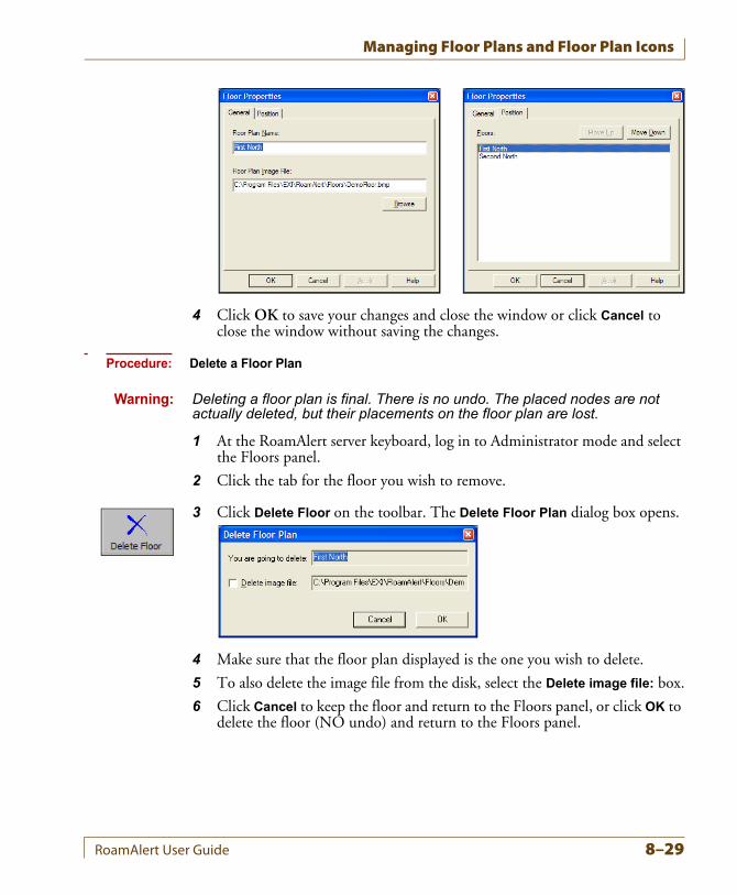
Managing Floor Plans and Floor Plan Icons
4 Click OK to save your changes and close the window or click Cancel to close the window without saving the changes.
Procedure: Delete a Floor Plan
Warning: Deleting a floor plan is final. There is no undo. The placed nodes are not actually deleted, but their placements on the floor plan are lost.
1 At the RoamAlert server keyboard, log in to Administrator mode and select the Floors panel.
2 Click the tab for the floor you wish to remove.
3 Click Delete Floor on the toolbar. The Delete Floor Plan dialog box opens.
4 Make sure that the floor plan displayed is the one you wish to delete.
5 To also delete the image file from the disk, select the Delete image file: box.
6 Click Cancel to keep the floor and return to the Floors panel, or click OK to delete the floor (NO undo) and return to the Floors panel.
RoamAlert User Guide 8–29
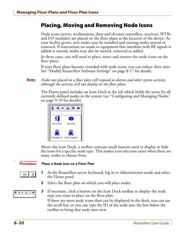
Managing Floor Plans and Floor Plan Icons
Placing, Moving and Removing Node IconsNode icons (server, workstations, door and elevator controllers, receivers, WTRs and I/O modules) are placed on the floor plans at the location of the device. As your facility grows, new nodes may be installed and existing nodes moved or removed. If renovations are made or equipment that interferes with RF signals is added or moved, nodes may also be moved, removed or added.In these cases, you will need to place, move and remove the node icons on the floor plans.If your floor plans become crowded with node icons, you can reduce their sizes. See “Modify RoamAlert Software Settings” on page 8-17 for details.
Note: Nodes not placed on a floor plan still respond to alarms and other system activity, although the activity will not display on the floor plans.
The Floors panel includes an Icon Dock at the left which holds the icons for all currently defined nodes in the system (see “Configuring and Managing Nodes” on page 9-10 for details).
Above the Icon Dock, a toolbar contains small buttons used to display or hide the icons for a specific node type. This makes icon selection easier when there are many nodes to choose from.
Procedure: Place a Node Icon on a Floor Plan
1 At the RoamAlert server keyboard, log in to Administrator mode and select the Floors panel.
2 Select the floor plan on which you will place nodes.
3 If necessary, click a button on the Icon Dock toolbar to display the node type you want to place on the floor plan.If there are more node icons than can be displayed in the dock, you can use the scroll bar, or you can type the ID of the node into the box below the toolbar to bring that node into view.
8–30 RoamAlert User Guide
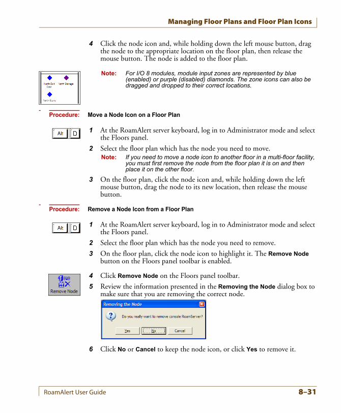
Managing Floor Plans and Floor Plan Icons
4 Click the node icon and, while holding down the left mouse button, drag the node to the appropriate location on the floor plan, then release the mouse button. The node is added to the floor plan.
Note: For I/O 8 modules, module input zones are represented by blue (enabled) or purple (disabled) diamonds. The zone icons can also be dragged and dropped to their correct locations.
Procedure: Move a Node Icon on a Floor Plan
1 At the RoamAlert server keyboard, log in to Administrator mode and select the Floors panel.
2 Select the floor plan which has the node you need to move.Note: If you need to move a node icon to another floor in a multi-floor facility,
you must first remove the node from the floor plan it is on and then place it on the other floor.
3 On the floor plan, click the node icon and, while holding down the left mouse button, drag the node to its new location, then release the mouse button.
Procedure: Remove a Node Icon from a Floor Plan
1 At the RoamAlert server keyboard, log in to Administrator mode and select the Floors panel.
2 Select the floor plan which has the node you need to remove.
3 On the floor plan, click the node icon to highlight it. The Remove Node button on the Floors panel toolbar is enabled.
4 Click Remove Node on the Floors panel toolbar.
5 Review the information presented in the Removing the Node dialog box to make sure that you are removing the correct node.
6 Click No or Cancel to keep the node icon, or click Yes to remove it.
RoamAlert User Guide 8–31
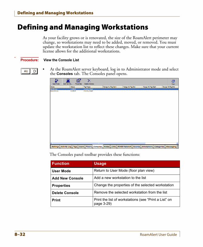
Defining and Managing Workstations
Defining and Managing WorkstationsAs your facility grows or is renovated, the size of the RoamAlert perimeter may change, so workstations may need to be added, moved, or removed. You must update the workstation list to reflect these changes. Make sure that your current license allows for the additional workstations.
Procedure: View the Console List
• At the RoamAlert server keyboard, log in to Administrator mode and select the Consoles tab. The Consoles panel opens.
The Consoles panel toolbar provides these functions:
Function Usage
User Mode Return to User Mode (floor plan view)
Add New Console Add a new workstation to the list
Properties Change the properties of the selected workstation
Delete Console Remove the selected workstation from the list
Print Print the list of workstations (see “Print a List” on page 3-29)
8–32 RoamAlert User Guide
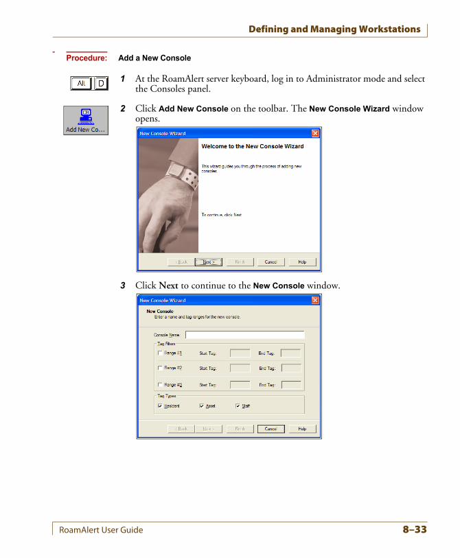
Defining and Managing Workstations
Procedure: Add a New Console
1 At the RoamAlert server keyboard, log in to Administrator mode and select the Consoles panel.
2 Click Add New Console on the toolbar. The New Console Wizard window opens.
3 Click Next to continue to the New Console window.
RoamAlert User Guide 8–33
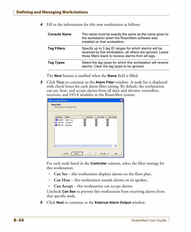
Defining and Managing Workstations
4 Fill in the information for this new workstation as follows:
The Next button is enabled when the Name field is filled.
5 Click Next to continue to the Alarm Filter window. A node list is displayed with check boxes for each alarm filter setting. By default, the workstation can see, hear, and accept alarms from all door and elevator controllers, receivers, and I/O-8 modules in the RoamAlert system.
For each node listed in the Controller column, select the filter settings for this workstation:
• Can See – this workstation displays alarms on the floor plan,
• Can Hear – this workstation sounds alarms on its speaker,
• Can Accept – this workstation can accept alarms.Uncheck Can See to prevent this workstation from receiving alarms from that specific node.
6 Click Next to continue to the External Alarm Output window.
Console Name The name must be exactly the same as the name given to the workstation when the RoamAlert software was installed on that workstation.
Tag Filters Specify up to 3 tag ID ranges for which alarms will be received by this workstation, all others are ignored. Leave these filters blank to receive alarms from all tags.
Tag Types Select the tag types for which this workstation will receive alarms. Clear the tag types to be ignored.
8–34 RoamAlert User Guide
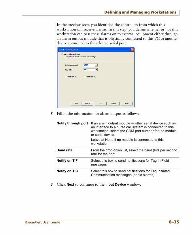
Defining and Managing Workstations
In the previous step, you identified the controllers from which this workstation can receive alarms. In this step, you define whether or not this workstation can pass these alarms on to external equipment either through an alarm output module that is physically connected to this PC or another device connected to the selected serial port.
7 Fill in the information for alarm output as follows:
8 Click Next to continue to the Input Device window.
Notify through port If an alarm output module or other serial device such as an interface to a nurse call system is connected to this workstation, select the COM port number for the module or serial device.
Leave at None if no module is connected to this workstation.
Baud rate From the drop-down list, select the baud (bits per second) rate for the port.
Notify on TIF Select this box to send notifications for Tag In Field messages
Notify on TIC Select this box to send notifications for Tag Initiated Communication messages (panic alarms)
RoamAlert User Guide 8–35
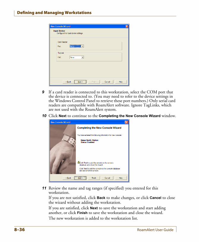
Defining and Managing Workstations
9 If a card reader is connected to this workstation, select the COM port that the device is connected to. (You may need to refer to the device settings in the Windows Control Panel to retrieve these port numbers.) Only serial card readers are compatible with RoamAlert software. Ignore TagLinks, which are not used with the RoamAlert system.
10 Click Next to continue to the Completing the New Console Wizard window.
11 Review the name and tag ranges (if specified) you entered for this workstation.If you are not satisfied, click Back to make changes, or click Cancel to close the wizard without adding the workstation.If you are satisfied, click Next to save the workstation and start adding another, or click Finish to save the workstation and close the wizard.The new workstation is added to the workstation list.
8–36 RoamAlert User Guide
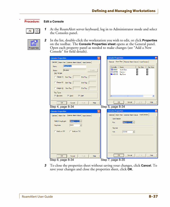
Defining and Managing Workstations
Procedure: Edit a Console
1 At the RoamAlert server keyboard, log in to Administrator mode and select the Consoles panel.
2 In the list, double-click the workstation you wish to edit, or click Properties on the toolbar. The Console Properties sheet opens at the General panel. Open each property panel as needed to make changes (see “Add a New Console” for field details).
3 To close the properties sheet without saving your changes, click Cancel. To save your changes and close the properties sheet, click OK.
Step 4, page 8-34 Step 5, page 8-34
Step 6, page 8-34 Step 7, page 8-35
RoamAlert User Guide 8–37
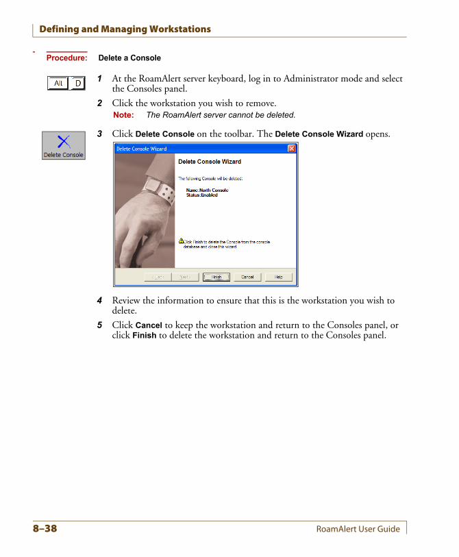
Defining and Managing Workstations
Procedure: Delete a Console
1 At the RoamAlert server keyboard, log in to Administrator mode and select the Consoles panel.
2 Click the workstation you wish to remove.Note: The RoamAlert server cannot be deleted.
3 Click Delete Console on the toolbar. The Delete Console Wizard opens.
4 Review the information to ensure that this is the workstation you wish to delete.
5 Click Cancel to keep the workstation and return to the Consoles panel, or click Finish to delete the workstation and return to the Consoles panel.
8–38 RoamAlert User Guide
Chapter 9CHAPTER 0CONFIGURING AND
MANAGING THE ROAMALERTNETWORK
RoamAlert network management procedures include:
• Performing system testing and backups
• Shutting down and restarting the system
• Viewing the system log
• Managing the network, nodes and links
RoamAlert network configuration procedures include:
• Configuring RS-485 networks
• Configuring nodes (controllers, receivers, I/O-8 modules, WTRs)
• Configuring links
Network configuration procedures (RS-485 network, node, and link tasks) are normally performed by the RoamAlert installation team. Since you have access to the configuration tools in Administrator mode, and you may be required to perform them, these procedures are documented here for your information.All network procedures (except shutting down and restarting workstations) can only be performed by an Administrator at the RoamAlert server.
Note: This information is offered for reference only. If you have any questions about installing devices or setting up the system, please consult your dealer or Stanley Healthcare Solutions. A complete discussion of these issues is contained in the RoamAlert Installation Manual.
RoamAlert User Guide 9–1
System Testing
System TestingYou should perform regular tests on the system to ensure that the controllers, receivers, and tags are operating properly.
ControllersCheck the operation of controllers at least once a month:
• walk into the detection field at a door with a working tag, which should lock the door (if so configured) and start an audible warning (TIF) at the local keypad.
• complete a bypass at each keypad to ensure correct operation.
ReceiversCheck the operation of receivers at least once a month.
TagsSee “Testing and Cleaning Tags” on page 7-11 for details.
9–2 RoamAlert User Guide
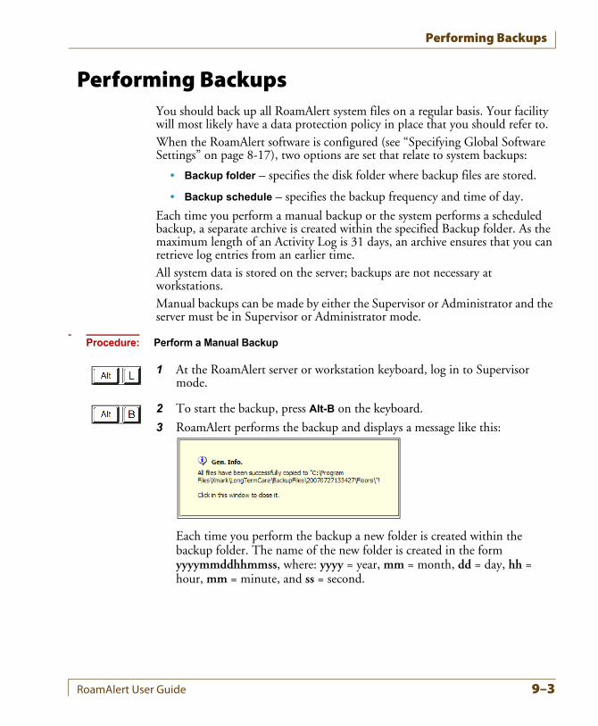
Performing Backups
Performing BackupsYou should back up all RoamAlert system files on a regular basis. Your facility will most likely have a data protection policy in place that you should refer to.When the RoamAlert software is configured (see “Specifying Global Software Settings” on page 8-17), two options are set that relate to system backups:
• Backup folder – specifies the disk folder where backup files are stored.
• Backup schedule – specifies the backup frequency and time of day.
Each time you perform a manual backup or the system performs a scheduled backup, a separate archive is created within the specified Backup folder. As the maximum length of an Activity Log is 31 days, an archive ensures that you can retrieve log entries from an earlier time.All system data is stored on the server; backups are not necessary at workstations.Manual backups can be made by either the Supervisor or Administrator and the server must be in Supervisor or Administrator mode.
Procedure: Perform a Manual Backup
1 At the RoamAlert server or workstation keyboard, log in to Supervisor mode.
2 To start the backup, press Alt-B on the keyboard.
3 RoamAlert performs the backup and displays a message like this:
Each time you perform the backup a new folder is created within the backup folder. The name of the new folder is created in the formyyyymmddhhmmss, where: yyyy = year, mm = month, dd = day, hh = hour, mm = minute, and ss = second.
RoamAlert User Guide 9–3
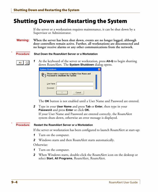
Shutting Down and Restarting the System
Shutting Down and Restarting the SystemIf the server or a workstation requires maintenance, it can be shut down by a Supervisor or Administrator.
Warning: When the server has been shut down, events are no longer logged, although door controllers remain active. Further, all workstations are disconnected and no longer receive alarms or any other communications from the network.
Procedure: Shut Down the RoamAlert Server or a Workstation
1 At the keyboard of the server or workstation, press Alt-Q to begin shutting down RoamAlert. The System Shutdown dialog opens.
The OK button is not enabled until a User Name and Password are entered.
2 Type in your User Name and press Tab or Enter, then type in your Password and press Enter or click OK.
If your User Name and Password are entered correctly, the RoamAlert system shuts down, otherwise an error message is displayed.
Procedure: Restart the RoamAlert Server or a Workstation
If the server or workstation has been configured to launch RoamAlert at start-up:
1 Turn on the computer.
2 Windows starts and then RoamAlert starts automatically.Otherwise:
1 Turn on the computer.
2 When Windows starts, double-click the RoamAlert icon on the desktop or select Start, All Programs, RoamAlert, RoamAlert.
9–4 RoamAlert User Guide
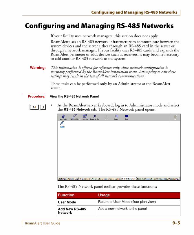
Configuring and Managing RS-485 Networks
Configuring and Managing RS-485 NetworksIf your facility uses network managers, this section does not apply.RoamAlert uses an RS-485 network infrastructure to communicate between the system devices and the server either through an RS-485 card in the server or through a network manager. If your facility uses RS-485 cards and expands the RoamAlert perimeter or adds devices such as receivers, it may become necessary to add another RS-485 network to the system.
Warning: This information is offered for reference only, since network configuration is normally performed by the RoamAlert installation team. Attempting to edit these settings may result in the loss of all network communications.
These tasks can be performed only by an Administrator at the RoamAlert server.
Procedure: View the RS-485 Network Panel
• At the RoamAlert server keyboard, log in to Administrator mode and select the RS-485 Network tab. The RS-485 Network panel opens.
The RS-485 Network panel toolbar provides these functions:
Function Usage
User Mode Return to User Mode (floor plan view)
Add New RS-485 Network
Add a new network to the panel
RoamAlert User Guide 9–5
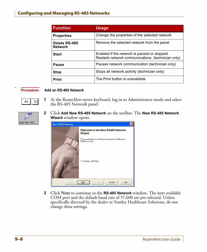
Configuring and Managing RS-485 Networks
Procedure: Add an RS-485 Network
1 At the RoamAlert server keyboard, log in to Administrator mode and select the RS-485 Network panel.
2 Click Add New RS-485 Network on the toolbar. The New RS-485 Network Wizard window opens.
3 Click Next to continue to the RS-485 Network window. The next available COM port and the default baud rate of 57,600 are pre-selected. Unless specifically directed by the dealer or Stanley Healthcare Solutions, do not change these settings.
Properties Change the properties of the selected network
Delete RS-485 Network
Remove the selected network from the panel
Start Enabled if the network is paused or stopped. Restarts network communications. (technician only)
Pause Pauses network communication (technician only)
Stop Stops all network activity (technician only)
Print The Print button is unavailable
Function Usage
9–6 RoamAlert User Guide
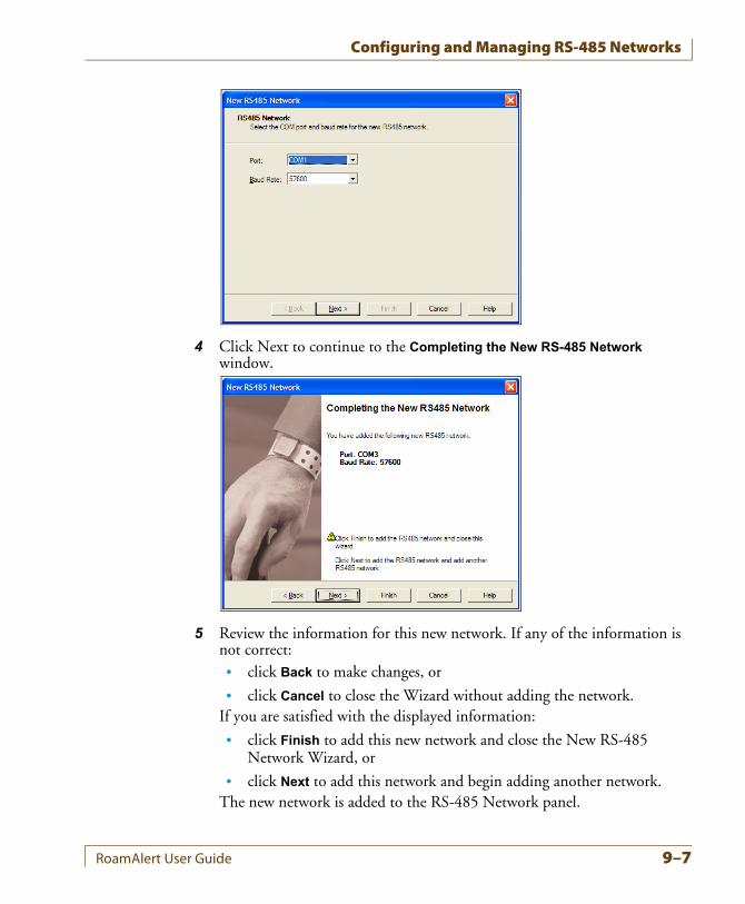
Configuring and Managing RS-485 Networks
4 Click Next to continue to the Completing the New RS-485 Network window.
5 Review the information for this new network. If any of the information is not correct:• click Back to make changes, or
• click Cancel to close the Wizard without adding the network.If you are satisfied with the displayed information:
• click Finish to add this new network and close the New RS-485 Network Wizard, or
• click Next to add this network and begin adding another network.The new network is added to the RS-485 Network panel.
RoamAlert User Guide 9–7
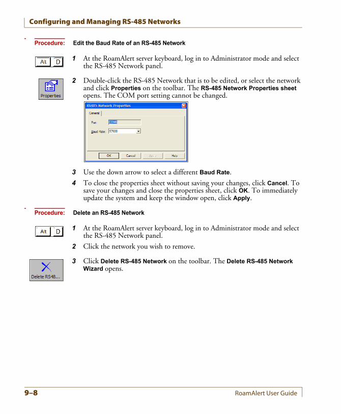
Configuring and Managing RS-485 Networks
Procedure: Edit the Baud Rate of an RS-485 Network
1 At the RoamAlert server keyboard, log in to Administrator mode and select the RS-485 Network panel.
2 Double-click the RS-485 Network that is to be edited, or select the network and click Properties on the toolbar. The RS-485 Network Properties sheet opens. The COM port setting cannot be changed.
3 Use the down arrow to select a different Baud Rate.
4 To close the properties sheet without saving your changes, click Cancel. To save your changes and close the properties sheet, click OK. To immediately update the system and keep the window open, click Apply.
Procedure: Delete an RS-485 Network
1 At the RoamAlert server keyboard, log in to Administrator mode and select the RS-485 Network panel.
2 Click the network you wish to remove.
3 Click Delete RS-485 Network on the toolbar. The Delete RS-485 Network Wizard opens.
9–8 RoamAlert User Guide
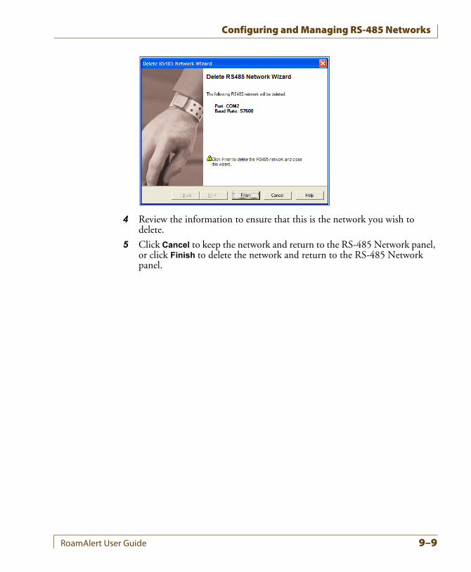
Configuring and Managing RS-485 Networks
4 Review the information to ensure that this is the network you wish to delete.
5 Click Cancel to keep the network and return to the RS-485 Network panel, or click Finish to delete the network and return to the RS-485 Network panel.
RoamAlert User Guide 9–9
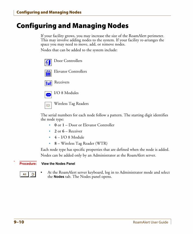
Configuring and Managing Nodes
Configuring and Managing NodesIf your facility grows, you may increase the size of the RoamAlert perimeter. This may involve adding nodes to the system. If your facility re-arranges the space you may need to move, add, or remove nodes.Nodes that can be added to the system include:
Door Controllers
Elevator Controllers
Receivers
I/O 8 Modules
Wireless Tag Readers
The serial numbers for each node follow a pattern. The starting digit identifies the node type:
• 0 or 1 – Door or Elevator Controller
• 2 or 6 – Receiver
• 4 – I/O 8 Module
• 8 – Wireless Tag Reader (WTR)
Each node type has specific properties that are defined when the node is added.Nodes can be added only by an Administrator at the RoamAlert server.
Procedure: View the Nodes Panel
• At the RoamAlert server keyboard, log in to Administrator mode and select the Nodes tab. The Nodes panel opens.
9–10 RoamAlert User Guide
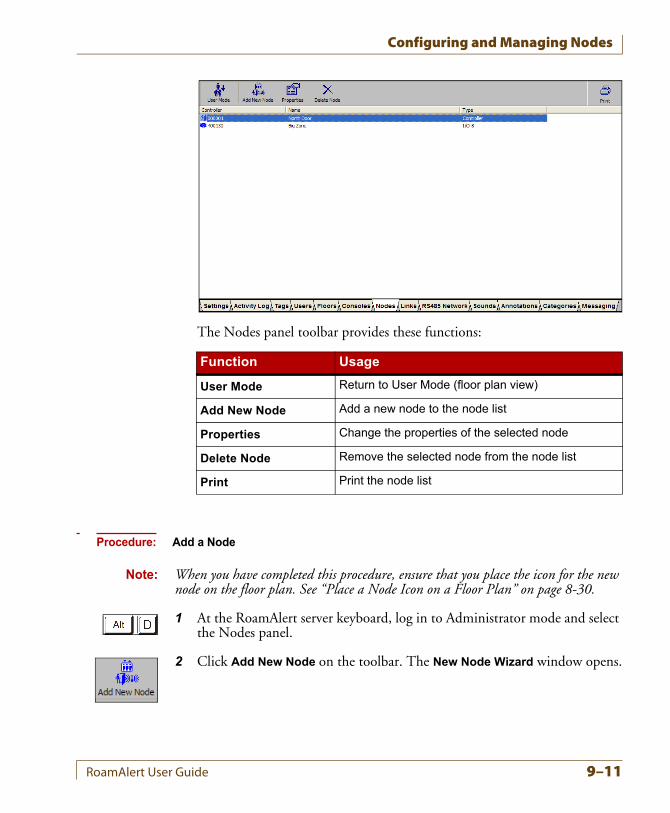
Configuring and Managing Nodes
The Nodes panel toolbar provides these functions:
Procedure: Add a Node
Note: When you have completed this procedure, ensure that you place the icon for the new node on the floor plan. See “Place a Node Icon on a Floor Plan” on page 8-30.
1 At the RoamAlert server keyboard, log in to Administrator mode and select the Nodes panel.
2 Click Add New Node on the toolbar. The New Node Wizard window opens.
Function Usage
User Mode Return to User Mode (floor plan view)
Add New Node Add a new node to the node list
Properties Change the properties of the selected node
Delete Node Remove the selected node from the node list
Print Print the node list
RoamAlert User Guide 9–11
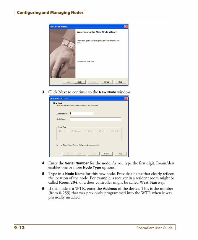
Configuring and Managing Nodes
3 Click Next to continue to the New Node window.
4 Enter the Serial Number for the node. As you type the first digit, RoamAlert enables one or more Node Type options.
5 Type in a Node Name for this new node. Provide a name that clearly reflects the location of the node. For example, a receiver in a resident room might be called Room 204, or a door controller might be called West Stairway.
6 If this node is a WTR, enter the Address of the device. This is the number (from 0-255) that was previously programmed into the WTR when it was physically installed.
9–12 RoamAlert User Guide
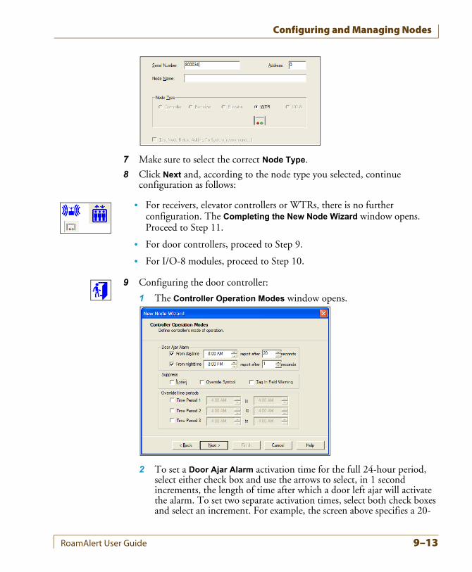
Configuring and Managing Nodes
7 Make sure to select the correct Node Type.
8 Click Next and, according to the node type you selected, continue configuration as follows:
• For receivers, elevator controllers or WTRs, there is no further configuration. The Completing the New Node Wizard window opens. Proceed to Step 11.
• For door controllers, proceed to Step 9.
• For I/O-8 modules, proceed to Step 10.
9 Configuring the door controller:
1 The Controller Operation Modes window opens.
2 To set a Door Ajar Alarm activation time for the full 24-hour period, select either check box and use the arrows to select, in 1 second increments, the length of time after which a door left ajar will activate the alarm. To set two separate activation times, select both check boxes and select an increment. For example, the screen above specifies a 20-
RoamAlert User Guide 9–13
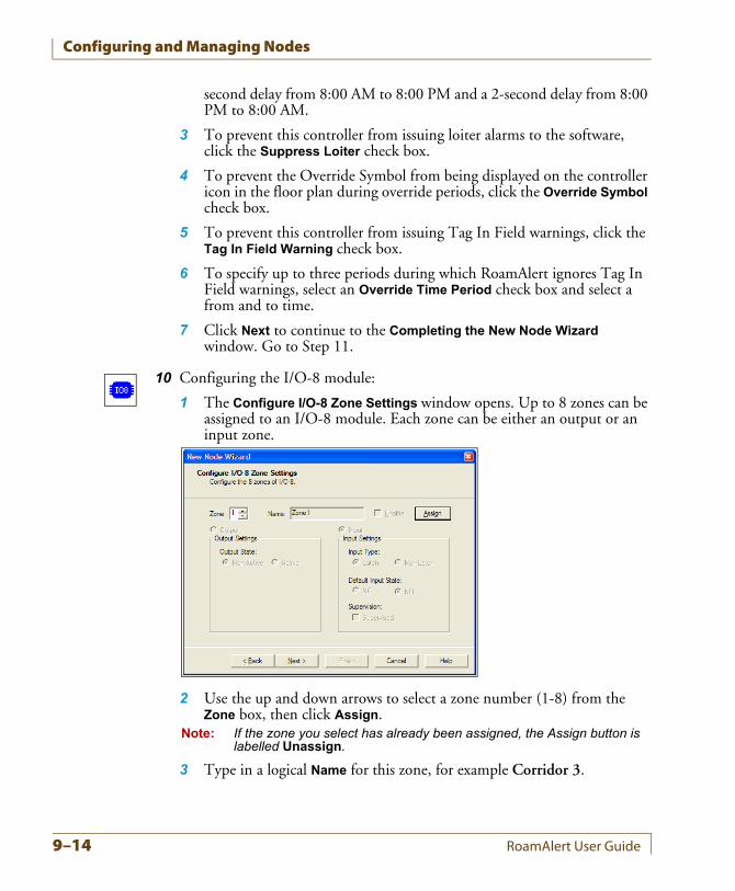
Configuring and Managing Nodes
second delay from 8:00 AM to 8:00 PM and a 2-second delay from 8:00 PM to 8:00 AM.
3 To prevent this controller from issuing loiter alarms to the software, click the Suppress Loiter check box.
4 To prevent the Override Symbol from being displayed on the controller icon in the floor plan during override periods, click the Override Symbol check box.
5 To prevent this controller from issuing Tag In Field warnings, click the Tag In Field Warning check box.
6 To specify up to three periods during which RoamAlert ignores Tag In Field warnings, select an Override Time Period check box and select a from and to time.
7 Click Next to continue to the Completing the New Node Wizard window. Go to Step 11.
10 Configuring the I/O-8 module:
1 The Configure I/O-8 Zone Settings window opens. Up to 8 zones can be assigned to an I/O-8 module. Each zone can be either an output or an input zone.
2 Use the up and down arrows to select a zone number (1-8) from the Zone box, then click Assign.
Note: If the zone you select has already been assigned, the Assign button is labelled Unassign.
3 Type in a logical Name for this zone, for example Corridor 3.
9–14 RoamAlert User Guide
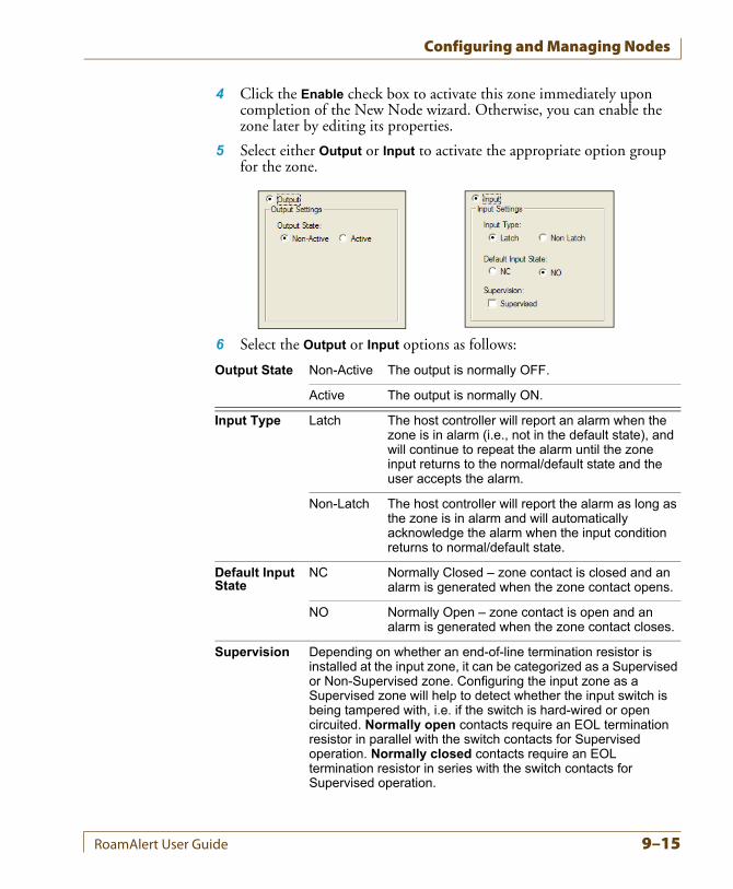
Configuring and Managing Nodes
4 Click the Enable check box to activate this zone immediately upon completion of the New Node wizard. Otherwise, you can enable the zone later by editing its properties.
5 Select either Output or Input to activate the appropriate option group for the zone.
6 Select the Output or Input options as follows:
Output State Non-Active The output is normally OFF.
Active The output is normally ON.
Input Type Latch The host controller will report an alarm when the zone is in alarm (i.e., not in the default state), and will continue to repeat the alarm until the zone input returns to the normal/default state and the user accepts the alarm.
Non-Latch The host controller will report the alarm as long as the zone is in alarm and will automatically acknowledge the alarm when the input condition returns to normal/default state.
Default Input State
NC Normally Closed – zone contact is closed and an alarm is generated when the zone contact opens.
NO Normally Open – zone contact is open and an alarm is generated when the zone contact closes.
Supervision Depending on whether an end-of-line termination resistor is installed at the input zone, it can be categorized as a Supervised or Non-Supervised zone. Configuring the input zone as a Supervised zone will help to detect whether the input switch is being tampered with, i.e. if the switch is hard-wired or open circuited. Normally open contacts require an EOL termination resistor in parallel with the switch contacts for Supervised operation. Normally closed contacts require an EOL termination resistor in series with the switch contacts for Supervised operation.
RoamAlert User Guide 9–15
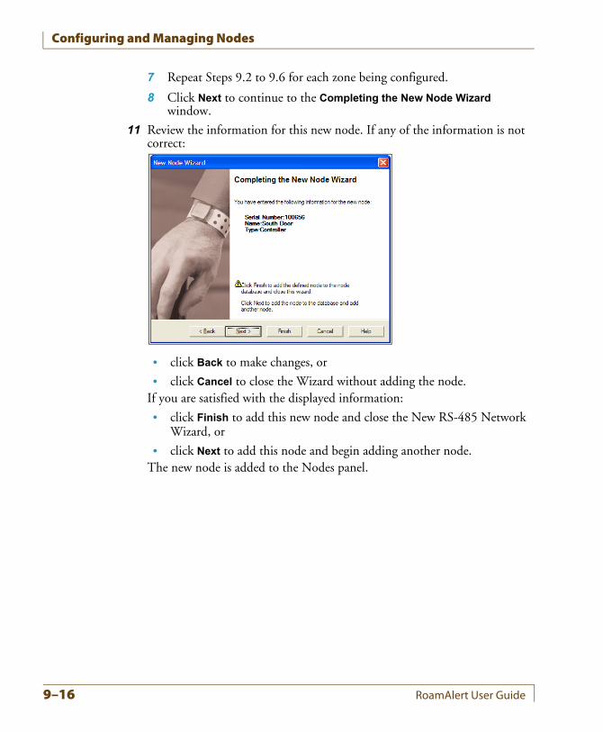
Configuring and Managing Nodes
7 Repeat Steps 9.2 to 9.6 for each zone being configured.
8 Click Next to continue to the Completing the New Node Wizard window.
11 Review the information for this new node. If any of the information is not correct:
• click Back to make changes, or
• click Cancel to close the Wizard without adding the node.If you are satisfied with the displayed information:
• click Finish to add this new node and close the New RS-485 Network Wizard, or
• click Next to add this node and begin adding another node.The new node is added to the Nodes panel.
9–16 RoamAlert User Guide
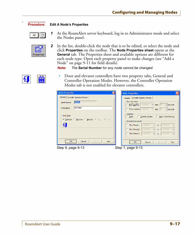
Configuring and Managing Nodes
Procedure: Edit A Node’s Properties
1 At the RoamAlert server keyboard, log in to Administrator mode and select the Nodes panel.
2 In the list, double-click the node that is to be edited, or select the node and click Properties on the toolbar. The Node Properties sheet opens at the General tab. The Properties sheet and available options are different for each node type. Open each property panel to make changes (see “Add a Node” on page 9-11 for field details). Note: The Serial Number for any node cannot be changed.
• Door and elevator controllers have two property tabs, General and Controller Operation Modes. However, the Controller Operation Modes tab is not enabled for elevator controllers.
Step 9, page 9-13 Step 1, page 9-13
RoamAlert User Guide 9–17
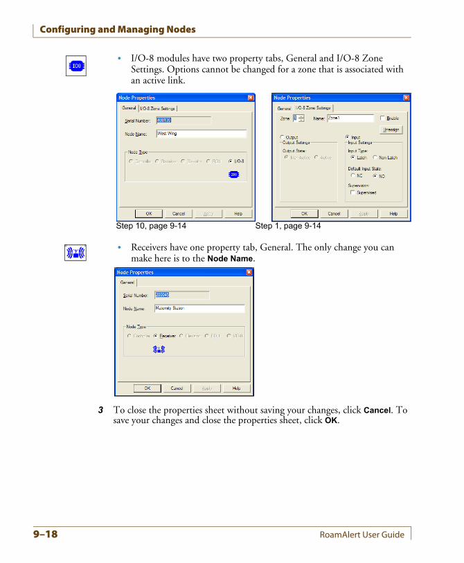
Configuring and Managing Nodes
• I/O-8 modules have two property tabs, General and I/O-8 Zone Settings. Options cannot be changed for a zone that is associated with an active link.
• Receivers have one property tab, General. The only change you can make here is to the Node Name.
3 To close the properties sheet without saving your changes, click Cancel. To save your changes and close the properties sheet, click OK.
Step 10, page 9-14 Step 1, page 9-14
9–18 RoamAlert User Guide
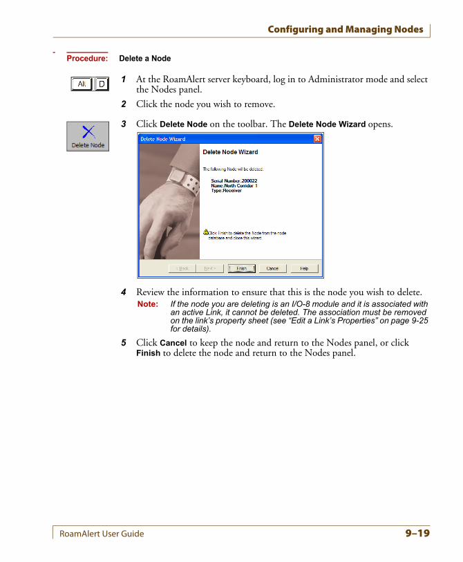
Configuring and Managing Nodes
Procedure: Delete a Node
1 At the RoamAlert server keyboard, log in to Administrator mode and select the Nodes panel.
2 Click the node you wish to remove.
3 Click Delete Node on the toolbar. The Delete Node Wizard opens.
4 Review the information to ensure that this is the node you wish to delete.Note: If the node you are deleting is an I/O-8 module and it is associated with
an active Link, it cannot be deleted. The association must be removed on the link’s property sheet (see “Edit a Link’s Properties” on page 9-25 for details).
5 Click Cancel to keep the node and return to the Nodes panel, or click Finish to delete the node and return to the Nodes panel.
RoamAlert User Guide 9–19
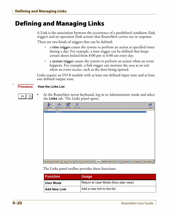
Defining and Managing Links
Defining and Managing LinksA Link is the association between the occurrence of a predefined condition (link trigger) and an operation (link action) that RoamAlert carries out in response.There are two kinds of triggers that can be defined:
• a time trigger causes the system to perform an action at specified times during a day. For example, a time trigger can be defined that keeps certain doors locked from 8:00 pm to 6:00 am every day.
• a system trigger causes the system to perform an action when an event happens. For example, a link trigger can monitor the area at an exit when an event occurs, such as the door being opened.
Links require an I/O-8 module with at least one defined input zone and at least one defined output zone.
Procedure: View the Links List
• At the RoamAlert server keyboard, log in to Administrator mode and select the Links tab. The Links panel opens.
The Links panel toolbar provides these functions:
Function Usage
User Mode Return to User Mode (floor plan view)
Add New Link Add a new link to the list
9–20 RoamAlert User Guide
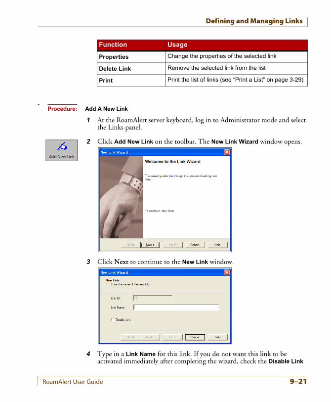
Defining and Managing Links
Procedure: Add A New Link
1 At the RoamAlert server keyboard, log in to Administrator mode and select the Links panel.
2 Click Add New Link on the toolbar. The New Link Wizard window opens.
3 Click Next to continue to the New Link window.
4 Type in a Link Name for this link. If you do not want this link to be activated immediately after completing the wizard, check the Disable Link
Properties Change the properties of the selected link
Delete Link Remove the selected link from the list
Print Print the list of links (see “Print a List” on page 3-29)
Function Usage
RoamAlert User Guide 9–21
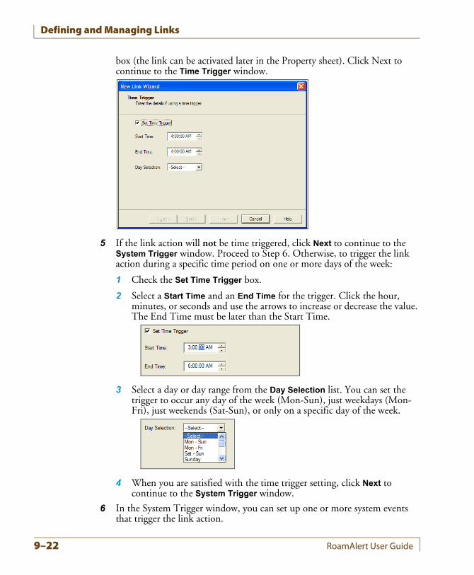
Defining and Managing Links
box (the link can be activated later in the Property sheet). Click Next to continue to the Time Trigger window.
5 If the link action will not be time triggered, click Next to continue to the System Trigger window. Proceed to Step 6. Otherwise, to trigger the link action during a specific time period on one or more days of the week:
1 Check the Set Time Trigger box.
2 Select a Start Time and an End Time for the trigger. Click the hour, minutes, or seconds and use the arrows to increase or decrease the value. The End Time must be later than the Start Time.
3 Select a day or day range from the Day Selection list. You can set the trigger to occur any day of the week (Mon-Sun), just weekdays (Mon-Fri), just weekends (Sat-Sun), or only on a specific day of the week.
4 When you are satisfied with the time trigger setting, click Next to continue to the System Trigger window.
6 In the System Trigger window, you can set up one or more system events that trigger the link action.
9–22 RoamAlert User Guide
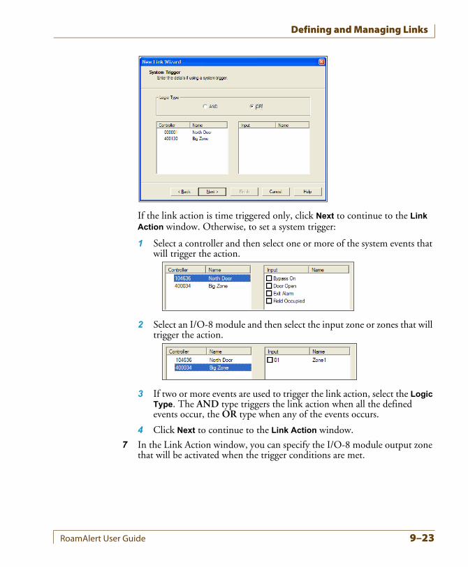
Defining and Managing Links
If the link action is time triggered only, click Next to continue to the Link Action window. Otherwise, to set a system trigger:
1 Select a controller and then select one or more of the system events that will trigger the action.
2 Select an I/O-8 module and then select the input zone or zones that will trigger the action.
3 If two or more events are used to trigger the link action, select the Logic Type. The AND type triggers the link action when all the defined events occur, the OR type when any of the events occurs.
4 Click Next to continue to the Link Action window.
7 In the Link Action window, you can specify the I/O-8 module output zone that will be activated when the trigger conditions are met.
RoamAlert User Guide 9–23
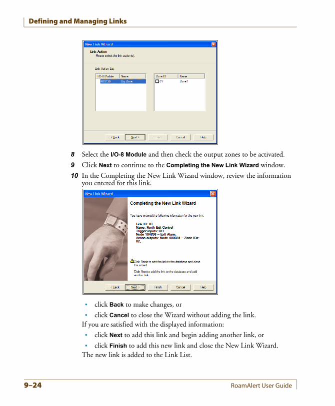
Defining and Managing Links
8 Select the I/O-8 Module and then check the output zones to be activated.
9 Click Next to continue to the Completing the New Link Wizard window.
10 In the Completing the New Link Wizard window, review the information you entered for this link.
• click Back to make changes, or
• click Cancel to close the Wizard without adding the link.If you are satisfied with the displayed information:
• click Next to add this link and begin adding another link, or
• click Finish to add this new link and close the New Link Wizard.The new link is added to the Link List.
9–24 RoamAlert User Guide
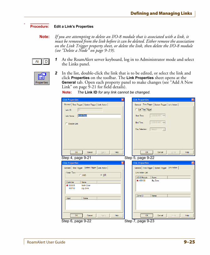
Defining and Managing Links
Procedure: Edit a Link’s Properties
Note: If you are attempting to delete an I/O-8 module that is associated with a link, it must be removed from the link before it can be deleted. Either remove the association on the Link Trigger property sheet, or delete the link, then delete the I/O-8 module (see “Delete a Node” on page 9-19).
1 At the RoamAlert server keyboard, log in to Administrator mode and select the Links panel.
2 In the list, double-click the link that is to be edited, or select the link and click Properties on the toolbar. The Link Properties sheet opens at the General tab. Open each property panel to make changes (see “Add A New Link” on page 9-21 for field details).Note: The Link ID for any link cannot be changed.
Step 4, page 9-21 Step 5, page 9-22
Step 6, page 9-22 Step 7, page 9-23
RoamAlert User Guide 9–25
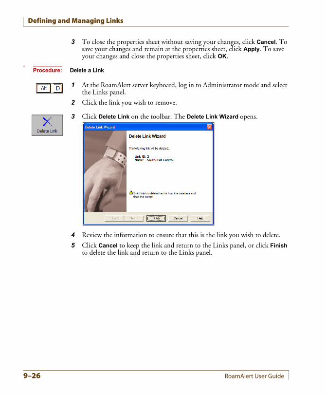
Defining and Managing Links
3 To close the properties sheet without saving your changes, click Cancel. To save your changes and remain at the properties sheet, click Apply. To save your changes and close the properties sheet, click OK.
Procedure: Delete a Link
1 At the RoamAlert server keyboard, log in to Administrator mode and select the Links panel.
2 Click the link you wish to remove.
3 Click Delete Link on the toolbar. The Delete Link Wizard opens.
4 Review the information to ensure that this is the link you wish to delete.
5 Click Cancel to keep the link and return to the Links panel, or click Finish to delete the link and return to the Links panel.
9–26 RoamAlert User Guide
Appendix ACHAPTER 0MANAGING ASSET TAGS
Asset tags can be attached to laptop computers, emergency carts, IV pumps and other mobile devices. Asset tags trigger exit alarms if the tagged item is taken through a protected exit without authorization. In a facility outfitted with receivers, a tamper alarm is recognized if the tag is removed, and tags can also be configured to emit a regular pulse so that the item can be located on the floor plan within the protected area. Without receivers, the system will not respond to tampered tags, but tags will still cause a door controller to react.This appendix describes the following tasks:
• Developing categories for asset tags
• Configuring alarms sounds for asset tags
• Adding and removing tags to and from inventory
• Assigning a tag to an item
• Physically attaching a tag to an item
• Removing, cleaning, and storing tags
• Editing tag properties
• Transporting tags
• Responding to tag alarms
RoamAlert User Guide A–1
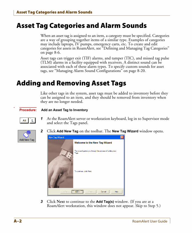
Asset Tag Categories and Alarm Sounds
Asset Tag Categories and Alarm SoundsWhen an asset tag is assigned to an item, a category must be specified. Categories are a way of grouping together items of a similar type. Examples of categories may include laptops, IV pumps, emergency carts, etc. To create and edit categories for assets in RoamAlert, see “Defining and Managing Tag Categories” on page 8-6.Asset tags can trigger exit (TIF) alarms, and tamper (TIC), and missed tag pulse (TLM) alarms in a facility equipped with receivers. A distinct sound can be associated with each of these alarm types. To specify custom sounds for asset tags, see “Managing Alarm Sound Configurations” on page 8-20.
Adding and Removing Asset TagsLike other tags in the system, asset tags must be added to inventory before they can be assigned to an item, and they should be removed from inventory when they are no longer needed.
Procedure: Add an Asset Tag to Inventory
1 At the RoamAlert server or workstation keyboard, log in to Supervisor mode and select the Tags panel.
2 Click Add New Tag on the toolbar. The New Tag Wizard window opens.
3 Click Next to continue to the Add Tag(s) window. (If you are at a RoamAlert workstation, this window does not appear. Skip to Step 5.)
A–2 RoamAlert User Guide
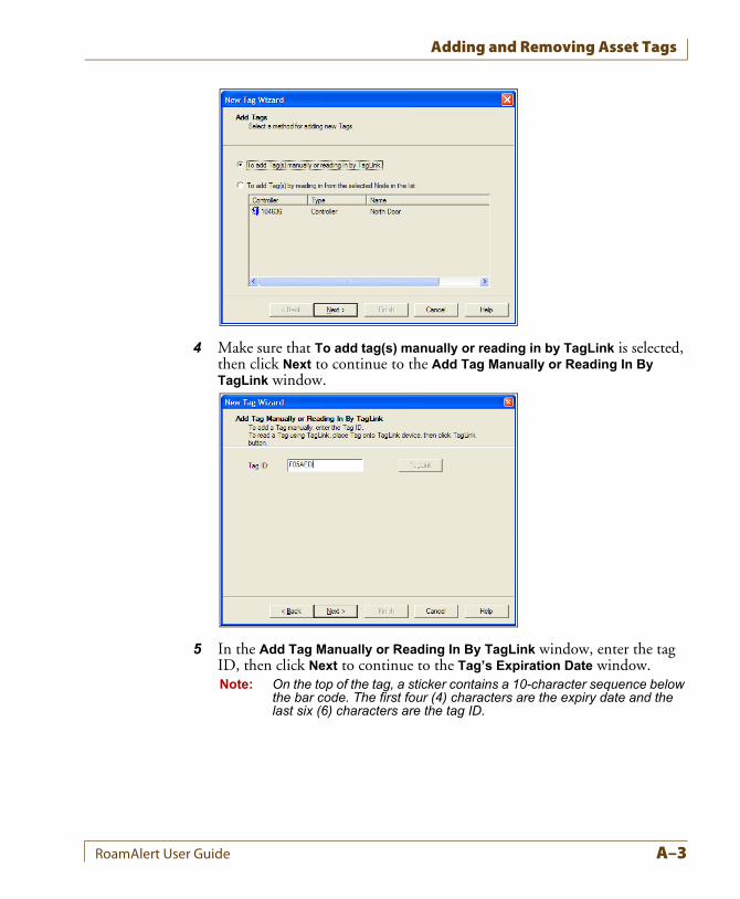
Adding and Removing Asset Tags
4 Make sure that To add tag(s) manually or reading in by TagLink is selected, then click Next to continue to the Add Tag Manually or Reading In By TagLink window.
5 In the Add Tag Manually or Reading In By TagLink window, enter the tag ID, then click Next to continue to the Tag’s Expiration Date window.Note: On the top of the tag, a sticker contains a 10-character sequence below
the bar code. The first four (4) characters are the expiry date and the last six (6) characters are the tag ID.
RoamAlert User Guide A–3
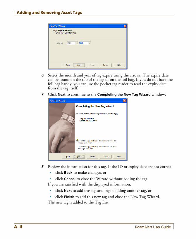
Adding and Removing Asset Tags
6 Select the month and year of tag expiry using the arrows. The expiry date can be found on the top of the tag or on the foil bag. If you do not have the foil bag handy, you can use the pocket tag reader to read the expiry date from the tag itself.
7 Click Next to continue to the Completing the New Tag Wizard window.
8 Review the information for this tag. If the ID or expiry date are not correct:• click Back to make changes, or
• click Cancel to close the Wizard without adding the tag.If you are satisfied with the displayed information:
• click Next to add this tag and begin adding another tag, or
• click Finish to add this new tag and close the New Tag Wizard.The new tag is added to the Tag List.
A–4 RoamAlert User Guide
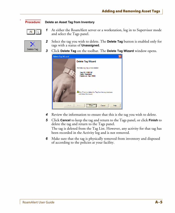
Adding and Removing Asset Tags
Procedure: Delete an Asset Tag from Inventory
1 At either the RoamAlert server or a workstation, log in to Supervisor mode and select the Tags panel.
2 Select the tag you wish to delete. The Delete Tag button is enabled only for tags with a status of Unassigned.
3 Click Delete Tag on the toolbar. The Delete Tag Wizard window opens.
4 Review the information to ensure that this is the tag you wish to delete.
5 Click Cancel to keep the tag and return to the Tags panel, or click Finish to delete the tag and return to the Tags panel.The tag is deleted from the Tag List. However, any activity for that tag has been recorded in the Activity log and is not removed.
6 Make sure that the tag is physically removed from inventory and disposed of according to the policies at your facility.
RoamAlert User Guide A–5
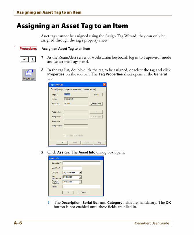
Assigning an Asset Tag to an Item
Assigning an Asset Tag to an ItemAsset tags cannot be assigned using the Assign Tag Wizard; they can only be assigned through the tag’s property sheet.
Procedure: Assign an Asset Tag to an Item
1 At the RoamAlert server or workstation keyboard, log in to Supervisor mode and select the Tags panel.
2 In the tag list, double-click the tag to be assigned, or select the tag and click Properties on the toolbar. The Tag Properties sheet opens at the General tab.
3 Click Assign. The Asset Info dialog box opens.
1 The Description, Serial No., and Category fields are mandatory. The OK button is not enabled until these fields are filled in.
A–6 RoamAlert User Guide
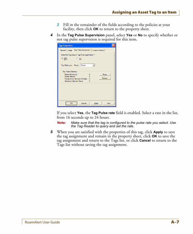
Assigning an Asset Tag to an Item
2 Fill in the remainder of the fields according to the policies at your facility, then click OK to return to the property sheet.
4 In the Tag Pulse Supervision panel, select Yes or No to specify whether or not tag pulse supervision is required for this item.
If you select Yes, the Tag Pulse rate field is enabled. Select a rate in the list, from 16 seconds up to 24 hours.Note: Make sure that the tag is configured to the pulse rate you select. Use
the Tag Reader to query and set the rate.
5 When you are satisfied with the properties of this tag, click Apply to save the tag assignment and remain in the property sheet, click OK to save the tag assignment and return to the Tags list, or click Cancel to return to the Tags list without saving the tag assignment.
RoamAlert User Guide A–7
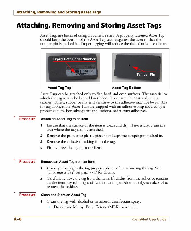
Attaching, Removing and Storing Asset Tags
Attaching, Removing and Storing Asset TagsAsset Tags are fastened using an adhesive strip. A properly fastened Asset Tag should keep the bottom of the Asset Tag secure against the asset so that the tamper pin is pushed in. Proper tagging will reduce the risk of nuisance alarms.
Asset Tags can be attached only to flat, hard and even surfaces. The material to which the tag is attached should not bend, flex or stretch. Material such as textiles, fabrics, rubber or material sensitive to the adhesive may not be suitable for tag application. Asset Tags are shipped with an adhesive strip covered by a protective film. For subsequent applications, order extra adhesives.
Procedure: Attach an Asset Tag to an Item
1 Ensure that the surface of the item is clean and dry. If necessary, clean the area where the tag is to be attached.
2 Remove the protective plastic piece that keeps the tamper pin pushed in.
3 Remove the adhesive backing from the tag.
4 Firmly press the tag onto the item.
Procedure: Remove an Asset Tag from an Item
1 Unassign the tag in the tag property sheet before removing the tag. See “Unassign a Tag” on page 7-17 for details.
2 Carefully remove the tag from the item. If residue from the adhesive remains on the item, try rubbing it off with your finger. Alternatively, use alcohol to remove the residue.
Procedure: Clean and Store an Asset Tag
1 Clean the tag with alcohol or an aerosol disinfectant spray.• Do not use Methyl Ethyl Ketone (MEK) or acetone.
Asset Tag Top Asset Tag Bottom
Expiry Date/Serial Number
Tamper Pin
A–8 RoamAlert User Guide
Responding to Asset Tag Alarms
• Ensure that no fluid enters the tamper pin opening. This will damage the electronic components.
• Do not submerge the tag in water or any other liquid.
2 Store the tag in its individual shielded bag. Store only one tag per bag.
Editing Asset Tag PropertiesThe properties of an asset tag are modified in the same manner as any other tag. See “Editing Tag Properties” on page 7-15 for details.However, note that an assigned tag cannot have its category changed. The tag must be unassigned and then reassigned in order to change the category. See “Unassign a Tag” on page 7-17 and “Assign an Asset Tag to an Item” on page A-6 for details.
Responding to Asset Tag AlarmsAn asset tag triggers alarms under these conditions:
• an exit alarm (TIF) when the tag approaches a protected door without either being transported or in the presence of an associated pendant,
• a tamper alarm (TIC) when the tag is removed from the item within the RoamAlert perimeter (if receivers are installed), or
• a missed tag pulse alarm when RoamAlert no longer receives TLMs (tag location messages) from the tag (if receivers are installed).
You respond to these alarms in the same manner as you do with any other tag. See “Accept an Alarm at the Server or a Workstation” on page 4-4 for details.
RoamAlert User Guide A–9
Responding to Asset Tag Alarms
A–10 RoamAlert User Guide
Appendix BCHAPTER 0TAG TESTING FORM
On the next page, we have provided a sample Test Result Record sheet. You can make photocopies for distribution or, using this template as an example, create your own form or spreadsheet.
RoamAlert User Guide B–1
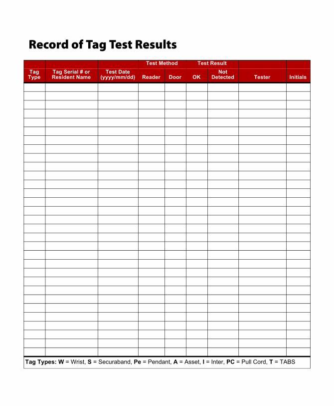
Record of Tag Test ResultsTest Method Test Result
TagType
Tag Serial # or Resident Name
Test Date(yyyy/mm/dd) Reader Door OK
NotDetected Tester Initials
Tag Types: W = Wrist, S = Securaband, Pe = Pendant, A = Asset, I = Inter, PC = Pull Cord, T = TABS
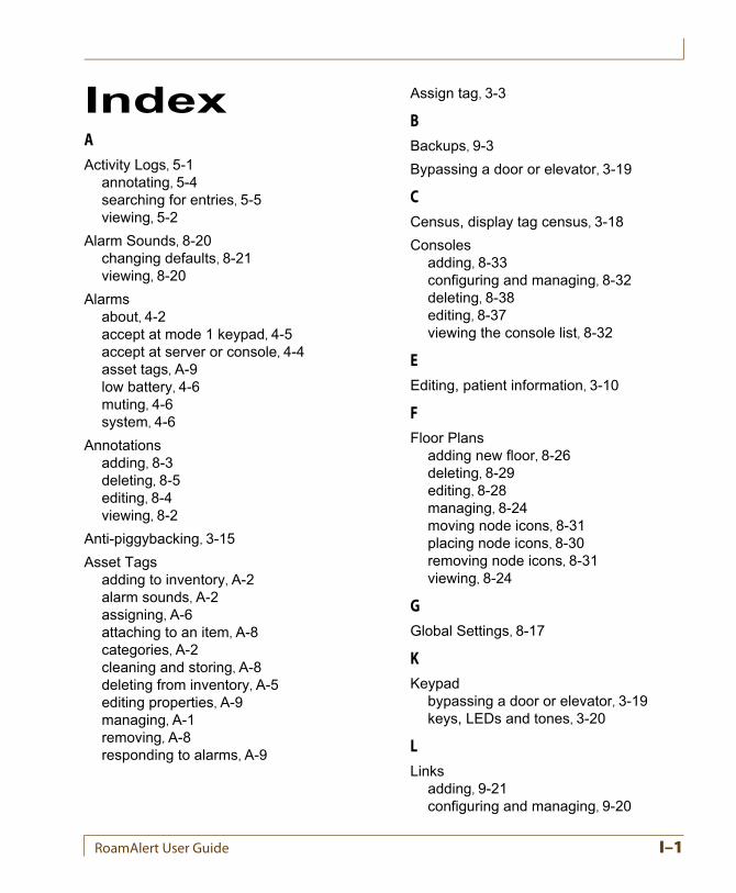
IndexAActivity Logs, 5-1
annotating, 5-4searching for entries, 5-5viewing, 5-2
Alarm Sounds, 8-20changing defaults, 8-21viewing, 8-20
Alarmsabout, 4-2accept at mode 1 keypad, 4-5accept at server or console, 4-4asset tags, A-9low battery, 4-6muting, 4-6system, 4-6
Annotationsadding, 8-3deleting, 8-5editing, 8-4viewing, 8-2
Anti-piggybacking, 3-15
Asset Tagsadding to inventory, A-2alarm sounds, A-2assigning, A-6attaching to an item, A-8categories, A-2cleaning and storing, A-8deleting from inventory, A-5editing properties, A-9managing, A-1removing, A-8responding to alarms, A-9
Assign tag, 3-3
BBackups, 9-3
Bypassing a door or elevator, 3-19
CCensus, display tag census, 3-18
Consolesadding, 8-33configuring and managing, 8-32deleting, 8-38editing, 8-37viewing the console list, 8-32
EEditing, patient information, 3-10
FFloor Plans
adding new floor, 8-26deleting, 8-29editing, 8-28managing, 8-24moving node icons, 8-31placing node icons, 8-30removing node icons, 8-31viewing, 8-24
GGlobal Settings, 8-17
KKeypad
bypassing a door or elevator, 3-19keys, LEDs and tones, 3-20
LLinks
adding, 9-21configuring and managing, 9-20
RoamAlert User Guide I–1
deleting, 9-26editing, 9-25triggers, 9-20viewing links list, 9-20
Logging on to Wizards, 3-2
MManual
audience, 1-3terms and conventions, 1-2
Messaging Devicesdeleting, 8-16editing, 8-15viewing, 8-12, 8-13
NNetwork Configuration, 9-1
Node Icons, see Floor Plans
Nodesadding, 9-11configuring and managing, 9-10deleting, 9-19editing, 9-17viewing nodes panel, 9-10
PPagers, see Messaging Devices
PIN Codes, assiging to users, 6-4
Printing Lists, 3-29
RRestarting RoamAlert, 9-4
RoamAlertnetwork configuration, 9-1performing backups, 9-3restarting, 9-4shutting down, 9-4software, 2-8system components, 2-4
system configuration, 8-1system testing, 9-2typical installation, 2-3
RS485 Networkadding, 9-6deleting, 9-8editing baud rate, 9-8viewing the network panel, 9-5
SScreen
administrator mode, 2-14supervisor mode, 2-13user mode, 2-11
Security levels, 2-8
Shutting Down RoamAlert, 9-4
Software Settings, 8-17modifying, 8-17
Sound Configuration, see Alarm Sounds
Staff Tags, 3-21
Switching Modeslog in to Adminstrator, 3-28log in to Supervisor, 3-27
System Configuration, 8-1
System Iconscomponents, 2-17sytem events, 2-17warnings and alarms, 2-17
TTag
display Census, 3-18editing information, 3-10return from transport, 3-16taking into controlled elevator, 3-21taking through controlled door, 3-20transporting, 3-13unassigning, 3-25
I–2 RoamAlert User Guide
Tag Categoriesadding, 8-7deleting, 8-10editing, 8-10viewing, 8-6
Tagssee also Asset Tagsadding multiple tags to inventory, 7-7adding to inventory manually, 7-4asset, A-1assigning and unassigning, 7-17attaching wrist tags, 3-8change expiry date, 7-19deleting from inventory, 7-10edit information and configuration, 7-20managing, 7-1return transported (property sheet), 7-22storing, 3-9
testing and cleaning, 7-11
Triggers, see Links
UUsers
assigning PIN codes, 6-4deleting, 6-7editing user information, 6-6managing, 6-1viewing the user list, 6-2
WWarnings
see Front Mattersystem icons, 2-17
Warranty, see Front Matter
Wizards, starting, 3-2
RoamAlert User Guide I–3