standards for approval of plans and …suffolkcountyny.gov/portals/0/documents and forms/health...
TRANSCRIPT

COUNTY OF SUFFOLK
STEVEN BELLONE
SUFFOLK COUNTY EXECUTIVE
SUFFOLK COUNTY DEPARTMENT OF HEALTH SERVICES
DIVISION OF ENVIRONMENTAL QUALITY
STANDARDS FOR APPROVAL OF PLANS AND CONSTRUCTION FOR
SEWAGE DISPOSAL SYSTEMS FOR SINGLE-FAMILY RESIDENCES
December 29, 2017
James L. Tomarken, MD, MPH, MBA, MSW Commissioner of Health Services
Walter Dawydiak, PE, JD
Director of Environmental Quality

Suffolk County Department of Health Services 12/29/17
Page | 1
SECTION PAGE
5-101 Introduction 4 5-102 Definitions Applicable to These Standards 4 5-103 Prohibitions of Subsurface Sewage Disposal Systems 7 5-104 Plans/Permits/Approvals Required 7 5-105 Siting of Subsurface Sewage Disposal Systems 10 5-106 Subsoil and Groundwater Criteria for Subsurface Systems 11 5-107 Minimum System Requirements 14 5-108 Construction Material Requirements 15 5-109 Septic Tank Requirements 15 5-110 Leaching Structure/System Requirements 20 5-111 Cover and Chimney/Riser Requirements 30 5-112 Distribution Box and Manhole Requirements 31 5-113 Sewer Line Requirements 34 5-114 Innovative and Alternative Wastewater Treatment Systems 35 5-115 Alternative Systems 43 5-116 Other Systems 43 5-117 Separation of Water and Sewer Lines 44 5-118 Final Grading and Backfilling 45 5-119 Sewage Ejector Systems 46 5-120 Abandonment of Existing Sewage Disposal Systems 47 5-121 Variances 48 5-122 Approval by the Commissioner of Health Services 48

Suffolk County Department of Health Services 12/29/17
Page | 2
TABLES PAGE
No. 1 Minimum Separation Distances to Sewage Disposal Systems 49
No. 2A Minimum Septic Tank Capacities 50
No. 2B Maximum Septic Tank Liquid Depth 50
No. 3 Minimum I/A OWTS Capacities 50
No. 4 Minimum Leaching System Design for a Zero to Four Bedroom Residence 51
No. 5 Minimum Leaching System Design for a Five or Six Bedroom Residence 51
No. 6 Minimum Leaching Galley Design for Residential Projects 51
No. 7 Application Rates for Absorption Beds or Trench Leaching Systems 52
No. 8 Required Length for Standard Gravelless Absorption Trench 52
No. 9 Required Length for Gravelless Absorption Trench with 25% Reduction 53
No. 10 Required Length for Gravelless Absorption Trench with 33% Reduction 53
No. 11 Required Length of a Gravelless Geotextile Sand Filter Absorption Trench 54
No. 12 Required Area of a Gravelless Absorption Bed 54
No. 8 Loading Rates for PSD’s Using the Bottom Area of the Trench 55

Suffolk County Department of Health Services 12/29/17
Page | 3
FIGURES
No. 1 Typical Concrete Rectangular Septic Tank 56
No. 2 Typical Concrete Cylindrical 1250 Gallon Septic Tank with Slab 57
No. 3 Typical Concrete Cylindrical 1500 Gallon Septic Tank with Dome 58
No. 4 Typical Leaching Pool 59
No. 5 Typical Leaching Galley and Leaching Galley Layout 60
No. 6 Typical Sewage Systems for One to Four Bedroom Residence 61
No. 7 Typical Concrete Sampling Manhole Detail 62
No. 8 Typical Sewer Line Cleanouts 63
No. 9 Typical Concrete Distribution Box 64
No. 10 Alternative to Distribution Box 65
No. 11 Alternative Sewage Disposal System for High Groundwater for up to 3 Bedrooms 66
No. 12 Alternative Sewage Disposal System for High Groundwater for 4 Bedrooms 67
No. 13 Sewage Disposal System for High Groundwater for up to 4 Bedrooms 68
No. 14 Sewage Disposal System for High Groundwater for 5 to 6 Bedrooms 69
No. 15 Sewage Disposal System for High Groundwater for 7 to 8 Bedrooms 70
No. 16 Typical Gravelless Trench Open-Bottom Chamber Section Details 71
No. 17 Typical Gravelless Geotextile Sand Filter Trench Section Details 72
No. 18 Typical Gravelless Absorption Trench Layout Detail 73
No. 19 PSD Cross Section Details 74
No. 20 PSD Cross Section Details (Long Side) 75
No. 21 Typical Soil Percolation Test Arrangement 76

Suffolk County Department of Health Services 12/29/17
Page | 4
STANDARDS FOR APPROVAL OF PLANS AND CONSTRUCTION --
SEWAGE DISPOSAL SYSTEMS FOR SINGLE-FAMILY RESIDENCES
5-101 INTRODUCTION A. The purpose of these standards is to ensure a safe and sanitary means of disposing of
household wastewater. Properly designed, maintained and operated sewage disposal systems minimize the possibility of disease transmission and the potential for contamination of ground and surface waters.
B. These are Standards for the Suffolk County Department of Health Services for the
Administration of Section 760-502 of Article 5 (Sewage Disposal), Sections 760-605, 606, and 609 of Article 6, Section 760-710 of Article 7, and Article 19 of the Suffolk County Sanitary Code. Facilities designed and constructed in compliance with these Standards will be in compliance with these sections of the Suffolk County Sanitary Code.
C. The information presented in these Standards applies to parcels used for a single-family
residence(s) and associated accessory buildings, and only addresses sewage as herein defined. Other solid, liquid or gaseous emissions are subject to a separate review and approval by the Department. For details relating to other than single-family residences, refer to “Standards for Approval of Plans and Construction for Sewage Disposal Systems for Other Than Single-Family Residences.”
5-102 DEFINITIONS APPLICABLE TO THESE STANDARDS Absorption Area - An area to which wastewater is distributed for infiltration to the soil. Alternative System - A subsurface sewage disposal system which contains design elements not explicitly described herein or components that are arranged differently than shown in the conventional layouts of these standards. Backfill - 1) The operation of refilling an excavation, usually after some structure or pipe has been placed therein; 2) the material placed in an excavation in the process of backfilling. Basal area - The horizontal surface in a PSD designed to receive effluent. Building Sewer - The sewer line which extends from the building to the sewage disposal or sewer system. Cesspool - Any buried chamber, including, but not limited to any perforated metal tank, perforated concrete or block vault or hollow excavation, which receives direct discharges of wastewater from a building sewer for the purpose of collecting solids and discharging liquid to the surrounding soil. Clean-out - A device brought to grade to facilitate cleaning of sewer lines.

Suffolk County Department of Health Services 12/29/17
Page | 5
Conventional Septic System or Conventional Onsite Wastewater Treatment System (OWTS) - An onsite sanitary system consisting of a septic tank and any associated interconnecting piping, a leaching structure(s), leaching pools, or leaching galleys and any associated interconnecting piping that does not have any active or mechanical means of treatment or any supplemental filtration components. Department - The Suffolk County Department of Health Services. Design Flow - The volume of sewage to be used for the purpose of designing the size of the sewage disposal system. Design Professional - A person licensed or registered in the State of New York and authorized by the State Education Law to design the systems described in these Standards. Distribution Manhole/Box - A type of structure used to distribute equal volumes of sewage to multiple leaching structures, or sewage system components.
Groundwater - The subsurface water occupying the zone of saturation below the established water table. Highest Expected Groundwater - The highest expected groundwater elevation based upon the historic data of both the Department of Health Services and the United States Geological Survey. Hydraulic Loading - The daily design volume of sewage discharged from the site. Individual Sewerage System - Any onsite sanitary system consisting of a septic tank and/or I/A OWTS tank(s) with any associated interconnecting piping, a leaching structure(s) and any associated interconnecting piping. OWTS and I/A OWTS are classified as Individual Sewerage Systems. Innovative and Alternative Onsite Wastewater Treatment System(s) (I/A OWTS) - An onsite decentralized wastewater treatment system(s) that, at a minimum, is designed to reduce total nitrogen in treated effluent to 19 mg/l. An I/A OWTS can serve more than one parcel, but shall not be considered sewering, Community Sewerage Systems, or Modified Subsurface Sewage Disposal (denitrification) by the Department under the Suffolk County Sanitary Code. Invert Elevation - The lowest elevation of the inside of a sewer line, water line, or other piping.
Leaching Area - The effective sidewall and/or bottom absorption area in a leaching structure, absorption trench, pool, galley. For leaching pools and galleys, it shall be sidewall area only. Leaching Pool or Galley - A covered pit constructed with a perforated, reinforced concrete wall through which septic tank and/or I/A OWTS effluent will infiltrate the surrounding soil. Leaching Structure - A perforated structure placed below grade and conforming to these standards or 10NYCRR, Appendix 75-A from which septic tank and/or IA OWTS effluent will infiltrate the

Suffolk County Department of Health Services 12/29/17
Page | 6
surrounding soil. Maintenance Provider - A private entity hired by a Property Owner to provide operation and maintenance and contractual service of an I/A OWTS. Operation and Maintenance (O&M) - The act of performing tasks specified by the Department and / or the manufacturer of the I/A OWTS including, but not limited to, cleaning, inspection, and adjustment of control settings to ensure proper operation of I/A OWTS and related components. Operation and Maintenance Contract - A signed contract between the Property Owner and the Maintenance Provider setting forth all required Operation and Maintenance procedures and monitoring schedules along with effective dates of the contract.
OWTS Replacement - The abandonment and/or removal of an existing individual sewerage system or cesspool and installation of a new individual sewerage system. OWTS Retrofit - The modification or alteration of an existing cesspool or individual sewerage system. Such modification or alteration shall include, but not be limited to: the replacement or addition of a septic tank, grease trap, components of an I/A OWTS, lift station, pump station, distribution box or manhole to an existing Sewage disposal system; replacement or addition of new leaching structures to an existing sewage disposal system; or replacement, addition, or re-configuration of sewage disposal system piping, control panel, pumps or other appurtenances. Perched Groundwater - Groundwater which is separated from the main body of groundwater by an aquiclude (e.g. a clay lens). Pressurized Shallow Drainfield (PSD) – A leaching field placed in the upper 18 inches of the soil horizon that receives pressure-dosed effluent that has been pretreated by an I/A OWTS. Property Owner - The holder of the legal and/or equitable title to real property.
Registration - The approval process by which a Property Owner completes and submits routine documentation required by the Department so as to certify his/her/its ownership and use of an I/A OWTS. Responsible Management Entity - The Department, which shall administer and conduct a comprehensive set of activities and have the legal authority and technical capacity to ensure the long-term operation, maintenance, and management of all I/A OWTS. Sewage - The combination of human and household waste with water which is discharged to the home plumbing system including the waste from a flush toilet, bath, sink, lavatory, dishwashing or laundry machine, or the water-carried waste from any other fixture, equipment or machine, together with such groundwater infiltration and surface water as may be present. Septic Tank - A watertight chamber used for the settling, stabilizing and anaerobic decomposition of sewage.

Suffolk County Department of Health Services 12/29/17
Page | 7
Sewage Disposal System - Any plumbing or conveyances which result in or are capable of resulting in a discharge of sewage. This includes, but is not limited to, building sewers, septic tanks, I/A OWTS leaching structures, sumps, tile fields, holding tanks, treatment works, outfalls, and connecting piping. The term may also refer to a part of a larger disposal system.
Sewer Line - A pipe designed to convey sewage.
Sewer System - (also referred to as sewerage system, public sanitary sewer, municipal sewage disposal system, privately owned communal sewerage system, and communal sewage disposal system) Pipe lines, conduits, pumping stations, and force mains, and all other constructions, devices, and appliances appurtenant thereto, used for conveying sewage, to a point of ultimate disposal.
Single-Family Residence - A dwelling unit; one or more rooms with provision for living, cooking, sanitary and sleeping facilities arranged for the use of one family.
Subsurface Sewage Disposal System - A sewage disposal system designed to treat and dispose of septic tank, I/A OWTS or other treatment facility effluent, in the absence of a community sewerage system, sewage treatment system or modified subsurface sewage disposal system, by application of the effluent to a soil surface at a depth below the surface of the ground.
Treatment Works - A facility designed for the purposes of removing certain components from sewage by mechanical, chemical or biological means, and stabilizing and disposing of sewage. The facility shall meet New York State Department of Environmental Conservation discharge requirements. I/A OWTS are not treatment works.
5-103 PROHIBITIONS OF SUBSURFACE SEWAGE DISPOSAL SYSTEMS/USE OF SEWAGE DISPOSAL SYSTEMS A. The installation of a sewage disposal system(s) is prohibited by the Suffolk County Sanitary Code
unless a permit to construct has been issued by the Commissioner.
B. The installation of an I/A OWTS is prohibited unless a permit to construct the I/A OWTS has been issued by the Department.
C. The occupancy of a building(s) and/or the use of a sewage disposal system(s) is prohibited without (final) approval of constructed works by the Department.
D. The installation of individual subsurface sewerage system(s) or alternative sewage disposal
system(s) is prohibited when the site to be developed is within the boundaries of a municipal sewer district or is served by an on-site/community sewage treatment system.
5-104 PLANS/PERMITS/APPROVALS REQUIRED A. P LANS/PERMITS REQUIRED TO CONSTRUCT
1. Written approval of a site plan/survey is required before start of construction of any new

Suffolk County Department of Health Services 12/29/17
Page | 8
sewage disposal system. Plans shall be prepared by a Design Professional and shall conform to guidelines issued by the Department. These site plans/surveys, once signed and approved by an authorized representative of the Department, become a permit to construct. Refer to the instructions included with the appropriate residential application for your project. Plan approval is not required for additions (overflows) to existing residential sewage disposal systems, but these Standards shall be used as a guideline for construction.
2. Permits are required for all new sewage disposal systems. Consult the Department to
determine if permits are required for modifications to existing systems such as those servicing new single-family residences, home additions, and accessory structures.
3. Permits are required for all new I/A OWTS and modifications to existing I/A OWTS
including, but not limited to, those servicing new single-family residences, existing single-family residences, home additions, and accessory structures.
a. Applicants applying for an OWTS Retrofit or OWTS Replacement of an existing
sewage disposal system with an approved I/A OWTS shall meet the requirements of these Standards to the greatest extent possible. The Department may permit reduced sewage disposal system setbacks per Table 1 or reduced minimum system capacity without the need for a variance or waiver in accordance with the Suffolk County Sanitary Code on a case-by-case basis. If necessary, certain requirements under these Standards may be relaxed at the discretion of the department provided the following:
i. An application for OWTS Replacements or OWTS Retrofits shall not propose any change of use, increase in bedrooms, building renovation, building addition, or any increased flow to the OWTS.
ii. The protection of public health and the environment is given priority over all other considerations.
iii. The proposed system does not reduce the setbacks to neighboring private wells as compared to the current system being replaced or retrofitted.
iv. The Design Professional certifies that the OWTS Replacements or OWTS Retrofits application meets the Standards to the greatest extent possible and that other alternatives are not feasible.
v. The Design Professional certifies that the OWTS Replacements or OWTS Retrofits application represents an improvement to existing conditions.
vi. For some applications, the Department may require a covenant to be filed against the property indicating the sewage disposal system does not comply with Department standards for OWTS Replacements or OWTS Retrofits.
b. The Department may allow an OWTS Application for Retrofit to be submitted when a fire or other catastrophic occurrence necessitates that a structure served by an OWTS be replaced.
4. In addition to providing for the public health and the environment, there must be
reasonable assurance that a system will be able to remain in satisfactory service without incurring large capital reinvestment over the lifetime of the facility.

Suffolk County Department of Health Services 12/29/17
Page | 9
5. The Design Professional retained to design the sewage disposal system shall be responsible for all aspects of the system design. That responsibility includes gathering all design information as necessary, making the site evaluation, and creating the design. These Standards shall not be construed as providing sufficiently detailed guidance as to relieve the Design Professional from undertaking whatever additional steps or measures that may be necessary to achieve an appropriate design.
6. Permits from other agencies, where such permits may affect placement of the sewage
disposal systems, shall be submitted to the Department prior to the Department’s issuance of a permit to construct. Such permits include, but are not limited to, wetlands or natural resources permits from the New York State Department of Environmental Conservation, the Army Corps of Engineers, and/or the appropriate local regulatory authority (e.g. delegated agents for administration of New York State Environmental Conservation Law (NYSECL) Articles 15, 24, 25; Wild, Scenic & Recreational Rivers; Town Natural Resources Permits; etc.).
B. CERTIFICATION OF CONSTRUCTION REQUIRED (FINAL APPROVAL)
1. Sewage disposal systems for single-family residences in Suffolk County shall be constructed to conform to these Standards. Applicants are required to obtain Department certification of conformance to these Standards.
2. Prior to backfilling, the installed sewage disposal system shall be inspected and authorized
for backfilling by a representative of the Department. In the case of buildings to be served by sewers, the Sewer District is usually the designated representative of the Department. Otherwise, the Department shall be notified at least twenty-four (24) hours in advance. Failure to contact the Department for inspection prior to backfilling may result in re-excavation of backfill. No approval or permit will be made or issued by the Department unless there is compliance with these requirements.
3. Certification of completed construction will be granted to the applicant on “as built” plans
which are to be submitted after the final satisfactory field inspection is completed. These plans shall include accurate measurements from permanent, fixed reference points to each component of the sewage disposal system and the water supply well or public water service line. These plans are to be signed and sealed by a design professional.
4. In addition to the submission of “as-built” plans, the applicant is responsible for submitting
all other documents required to obtain “Final Approval” from the Department. Refer to bulletin on “Instructions for Obtaining Final Approval for Single Family Residences,” Bulletin Number WWM-041(latest revision) and the Permit Conditions provided with the Department’s approved plans for construction (form WWM-058), for more details. Occupancy of a building or discharge to any sewage disposal system is prohibited without the final approval/certification of construction issued by the Department.

Suffolk County Department of Health Services 12/29/17
Page | 10
5-105 SITING OF SUBSURFACE SEWAGE DISPOSAL SYSTEMS A. PRIORITY FOR SEWAGE DISPOSAL SYSTEM
Because the failure of a sewage disposal system has the potential for significant public health impacts, first priority during planning shall be given to the location of sewage disposal systems over the location of other improvements on the property.
1. CONSIDER ALL FACTORS CAREFULLY. The design professional is responsible to
carefully consider the significance of the existing and proposed topography, soils, locations of existing and proposed water supply wells, surface waters and wetlands, groundwater conditions, and the planned locations of other improvements such as foundations, driveways, and construction on adjacent properties, property lines and other limitations of a physical or legal nature.
2. A SUPERIOR SITE SHALL NOT BE FOREGONE. A disposal site available prior to
development which is adequate for installation of a disposal system which can conform to these standards, or be more in compliance with these standards than other potential disposal sites, shall not be sacrificed to enhance the siting of other improvements being considered for the site.
B. SITE CONDITIONS PROHIBITED. Sewage disposal systems shall not be located: 1. In areas with a surface elevation lower than the 10-year flood level;
2. In any area subject to imminent erosion, which cannot be controlled so as to protect the sewage disposal system;
3. In areas where the maximum high groundwater level is less than one foot below the original ground surface;
4. In areas with slopes greater than 15%;
5. In areas where the existing subsoils contain meadow mat, bog, silts, clays, or other impervious material extending below the groundwater table;
6. In areas where groundwater conditions are not conducive to the proper functioning of subsurface sewage disposal systems;
7. In a swale;
8. Where the topography concentrates runoff onto or into the area where the system is proposed;
9. Where surface water discharges would be induced to artificially raise the groundwater level below the system;
10. In any area or under any part of a building, roadway, driveway, or other improvement that does or may prevent reasonable access for repair or maintenance of the system. (Note systems may be approved to be located under a driveway at the discretion of the Department if proven absolutely necessary.)

Suffolk County Department of Health Services 12/29/17
Page | 11
C. SITE CONDITION REQUISITES. Sewage disposal systems shall be located: 1. On land owned in fee by the Applicant;
2. On the same parcel as the building to be serviced; 3. In an unimproved area which allows adequate access for maintenance and fifty percent
expansion of the leaching facilities. Deepening the system is not permitted in lieu of providing this expansion area;
4. In the “front yard.” A location other than the front yard will be considered in order to
protect drinking supply wells and to accommodate unique site conditions (i.e. steep slopes, existing house connection locations, etc.), provided it is in conformance with the other aspects of these Standards and reasonable permanent access is available for maintenance and repair of the system;
5. At least sixty-five (65) feet from bluffs or landward of the dwelling;
6. In conformance with the minimum separation distances for subsurface sewage disposal
systems presented in Table 1. 5-106 SUBSOIL AND GROUNDWATER CRITERIA FOR SUBSURFACE SYSTEMS A. SOIL INVESTIGATION
Subsoil conditions shall be shown on the plan. The nature of the soil shall be determined by excavation of one or more test holes or borings at the site of the proposed subsurface sewage disposal system. Test holes/borings must be in the vicinity of the proposed leaching structure(s). The soil investigation shall be subject to the following conditions: 1. The soils in a test holes/borings shall be classified using the ASTM Unified Soil
Classification System (ASTM D-2487) as a reference. The test hole/borings shall be carried to a depth of six feet in excess of the proposed leaching structure bottom or, in the case of unusual soil, until a strata of six feet of sand and gravel is reached (defined as SP or SW by ASTM standards). The test holes/borings shall be a minimum of seventeen (17) feet deep or six feet into groundwater. A test hole/boring log and grade elevation at the test hole/borings location shall be indicated on the plan.
2. The design professional, by providing this information on the submitted plan, is considered
as certifying the results. Test holes/borings listed as “by others” are unacceptable unless independently certified by a design professional. Test holes/borings undocumented as to date, time and location of test are not acceptable.
3. Additional test holes/borings witnessed by a representative of the Department may be
required prior to approval to construct in areas of unusually poor soils or where data on record with the Department indicates inconsistent conditions.

Suffolk County Department of Health Services 12/29/17
Page | 12
4. When installing leaching structures, unsuitable soils shall be removed and replaced with sand and gravel, acceptable to the Department, a three-foot collar extending down into minimum six-foot strata of acceptable sand and gravel. In those areas where these criteria cannot be met, consult the Department.
5. When installing a leaching pool(s) or galley(s) in sand and gravel (defined as SP or SW by
ASTM standards) a minimum of 300 square feet of leaching area shall be provided for up to a four-bedroom residence and 400 square feet of leaching area for a five to six-bedroom residence. Dwellings greater than six bedrooms shall provide an additional 75 square feet of leaching area for each bedroom.
B. SOIL PERCOLATION TESTS
1. For leaching structures/systems, other than leaching pools or leaching galleys, that are not to be installed in sand and gravel (defined as SP or SW by ASTM standards) acceptable to the Department, soil percolations tests may be used to design the system.
2. Unless otherwise stated, soil percolation tests must be performed in accordance with
10NYCR, Appendix 75-A and the NYSDOH “Residential Onsite Wastewater Treatment Systems Design Handbook.”
3. Soil percolation test results must be certified by a Licensed Professional Engineer or
Licensed Registered Architect and submitted to the Department for review.
4. At least two percolation tests for up to 1,000 sq. ft. of absorption area should be performed in holes spaced uniformly throughout the site. If soil conditions are highly variable, more tests may be required. An additional percolation test is required for each additional 500 sq. ft. of absorption area.
5. Percolation test shall be performed at the depth equivalent to the bottom of the proposed
leaching structure. 6. Acceptable application rates based on percolation rates are stated in Table 7 and Table
13. 7. A maximum leaching rate of 1.20 gallons per day per square feet of leaching is permitted
when using soil percolation test results to determine a leaching rate to calculate leaching area in lieu of installing leaching structures in sand and gravel (defined as SP or SW by ASTM standards). Maximum leaching rates for Pressurized Shallow Drainfields (PSD’s) are identified in section 5-110 F.
8. Leaching structures, other than leaching pools or leaching galleys, can be installed in soil
classified as sand and gravel (defined as SP or SW by ASTM standards), based on certified test hole/boring information obtained and designed using a maximum leaching rate of 1.20 gallons per day per square foot without the need for a soil percolation test (0.95 gallons per day per square feet for leaching absorption beds or maximum leaching rate for PSD’s stated in section 5-110F) provided one of the following criteria is met:

Suffolk County Department of Health Services 12/29/17
Page | 13
i. The bottom of the leaching structure will be placed on virgin strata of 4ft of sand
and gravel defined as SP or SWP by ASTM standards; or
ii. Soils are excavated to a 4ft strata of virgin sand and gravel defined as SP or SW by ASTM standards and then backfilled with clean sand and gravel defined as SP or SW.
9. When percolation test exceeds 60 minutes per inch (30 minutes per inch for an absorption
bed system) then 4ft of unsuitable soils shall be excavated below the elevation of the proposed bottom of the leaching structure and properly disposed. The excavation shall be backfilled with sand and gravel defined as SP or SW by ASTM standards and the lowest application rate shall be utilized to design the system.
10. In some case the Department may require reduced application rates based on an evaluation of leaching structure technology.
11. A percolation test is only an indicator of soil permeability and must be consistent with the
soil classification of the site as determined from the test holes.
12. Percolation Test Procedures (See FIGURE 21 for a typical soil percolation test layout):
a. Make sure proper construction safety practices are followed.
b.Dig a hole with vertical sides approximately 12 inches wide on all four (4) sides or 12 inches in diameter. The depth of the test holes should be equivalent to the bottom elevation of the leaching structure. It is necessary to place washed aggregate in the lower two (2) inches of each percolation test hole or to employ another method that will reduce scouring and silting action when water is poured into the hole. The sides of percolation holes should be scraped to avoid smearing.
c. Pre-soak the test hole by periodically filling the hole with water and allowing the
water to seep away. This procedure should be performed for at least four (4) hours and should begin one (1) day before the test, except in clean, coarse sand and gravel. After the water from the final pre- soaking has seeped away, remove any loose soil that has fallen from the sides of the hole. Pre- soaking saturates the surrounding soil and allows for clay in the soil to swell, simulating when a system is in operation and receiving wastewater effluent.
d.Pour clean water into the hole, with as little splashing as possible, to a depth of six
(6) inches above the bottom of the test hole.
e. Observe and record the time in minutes required for the water to drop from the six (6) inch depth to the five (5) inch depth.
f. Repeat the test a minimum of three (3) times until the time for the water to drop

Suffolk County Department of Health Services 12/29/17
Page | 14
from six (6) inches to five (5) inches for two (2) successive tests is approximately equal (i.e., ≤ 1 minutes for 1 – 30 min./inch; ≤ 2 minutes for 31-60 min./inch). The longest time interval to drop one (1) inch shall be taken as the stabilized rate of percolation and shall serve as the basis of design for the absorption system.
g.A percolation test where results are inconsistent with the deep soil test pit evaluation
should be disregarded, and the percolation test(s) performed again. C. GROUNDWATER INVESTIGATION
Groundwater elevation, if encountered shall be shown on soil test logs submitted on plans. All sanitary systems must be designed based upon the highest expected groundwater elevation, and noted as such on the plans. The plans are subject to the following conditions:
1. In areas subject to tidal action, groundwater elevations shall be measured at mean high tide
and be so noted on plans.
2. In cases where groundwater elevation is less than seven feet below surface elevation a grading plan is required to be shown on the plans. The grading plan shall indicate plan and profile views of the disposal system, the residence first floor, all waste pipe inverts, the top and bottom of sanitary structures, highest expected groundwater, the top and bottom of any retaining walls, and final grade elevation. The plan view shall indicate final grade by showing one foot contour lines for at least twenty (20) feet from the edge of the sanitary system. A grading plan may also be required for sites containing steep slopes.
D. DEPARTMENT INSPECTION PRIOR TO INSTALLATION
In the case of unacceptable soil and/or groundwater conditions, inspection of the excavation by a representative of the Department is required prior to the installation of the leaching structure.
5-107 MINIMUM SYSTEM REQUIREMENTS A. SEPTIC TANK CAPACITY
Septic tank minimum capacity shall be provided in accordance with Table 2A. The maximum liquid depth permitted in the septic tank is specified in Table 2B. In cases when an I/A OWTS must have a septic tank installed prior to the I/A OWTS unit. The capacity of a septic tank for an I/A OWTS shall be determined in accordance with I/A OWTS manufacturer recommendations.
B. I/A OWTS CAPACITY I/A OWTS minimum capacity shall be provided in accordance with Table 3. C. LEACHING POOL AREA, LEACHING GALLEY AREA, GRAVELLESS ABSORPTION

Suffolk County Department of Health Services 12/29/17
Page | 15
TRENCH LENGTH, AND ABSORPTION BED AREA
The minimum required leaching area or length is specified in Tables 4, 5, 6, 8, 9, 10, 11, and 12. 5-108 CONSTRUCTION MATERIAL REQUIREMENTS A. DEPARTMENT APPROVAL REQUIRED
All materials used in the sewage disposal system shall be approved by the Department prior to use.
B. APPROVAL PROCEDURE
1. Drawings of products which meet the functional design criteria of this code and which contain thereon the signed, dated manufacturer’s certification as to the structural integrity of the designed and manufactured product for the purpose intended shall be filed with the Department.
2. Once approved, a copy of the product drawing shall be kept on file in the Department.
Products so approved are approved for general use and do not require further or repeated product submittal or approval unless such approval is withdrawn by the Department.
C. PRODUCT IDENTIFICATION
All materials shall be identified as to manufacturer and have the identification visible at the time of inspection.
D. GUIDELINES USED BY THE DEPARTMENT
Compliance with the National Sanitation Foundation, The American Society of Testing and Materials, the International Association of Plumbing and Mechanical Officials and/or The American Water Works Association requirements and specifications shall be used as a guideline in reviewing applicable materials of construction for approval by the Department.
5-109 SEPTIC TANK REQUIREMENTS A. SEPTIC TANK CAPACITY
1. The liquid capacity of a residential septic tank shall be based on the number of bedrooms. The minimum tank capacity shall be one thousand gallons (1,000) for 3 bedrooms or less. Each additional bedroom shall require an additional two hundred and fifty (250) gallons. See Tables 2A and 2B.
2. Garbage grinders are strongly discouraged under this article. A residence with a garbage grinder shall require an increase in septic tank capacity by two hundred and fifty (250) gallons and an additional 75 square feet of leaching area.
3. Hot tubs and whirlpools that discharge directly to the onsite sewage disposal system are

Suffolk County Department of Health Services 12/29/17
Page | 16
discouraged under this article. A residence with a hot tub or whirlpool shall require an increase in septic tank capacity by two hundred and fifty (250) gallons and an additional seventy-five (75) square feet of leaching area for a leaching pool or leaching galley (other leaching structures shall be designed for an additional 110gpd of flow).
B. GENERAL SEPTIC TANK REQUIREMENTS
1. Septic tanks shall be constructed of precast concrete, fiberglass, polyethylene, polypropylene, thermoplastics, or other materials in accordance with 10NYCRR, Appendix 75-A. The use of steel septic tanks shall be prohibited under this article.
2. Typical concrete septic tank configurations are shown in Figures 1, 2, & 3. Alternate tank configurations may be accepted if designed in accordance with 10NYCRR, Appendix 75 A.
3. All septic tanks shall have (2) compartments meeting the following requirements:
a. The first compartment shall have a liquid volume of 50-75 percent of the required
liquid volume. b. All single unit septic tanks shall be divided into two compartments divided by a
traverse wall. The inlet compartment shall have 50-75 percent of the total capacity. c. The interior compartment wall (traverse wall) shall not extend to the interior roof
without providing for venting equivalent to the area of a four (4) inch diameter pipe. Recommend providing four-inch air gap at the top of the wall.
4. Septic tanks shall be watertight and constructed of sound and durable materials that are not
subject to excessive corrosion or decay.
a. All septic tanks must be watertight. Two methods of ensuring tanks are watertight shall be either vacuum testing or water pressure testing methods as follows:
1. Vacuum testing: Seal the empty tank and apply a vacuum to four (4) inches
(100mm) of mercury. The tank is approved if 90% of vacuum is held for two (2) minutes.
2. Water testing: Seal tank; fill tank with water to outlet invert elevation, let stand for 24 hours. Refill the tank to outlet invert after 24-hour period is complete. Let the tank stand for 10 hours. The tank is approved if water level is held for 10-hour. Water pressure testing is recommended to be done onsite after installation.
5. Access to each tank or compartment of the tank shall be provided by an access cover with an inside dimension of at least twenty inches diameter. All openings shall meet the following requirements:
a. Openings shall be provided over all inlet and outlet pipes. b. Access covers over the outlet pipe shall be brought to grade. Access covers over the
inlet pipe should be brought to within twelve inches of finished grade. Access covers at finished grade over all manhole openings are strongly encouraged. Access covers set at finished grade shall be locking, watertight, insect proof, flat, skid proof and be

Suffolk County Department of Health Services 12/29/17
Page | 17
approved for sewage use. Refer to section 5-111 for further cover and riser requirements.
c. Where extensions are required, they shall be watertight. d. Covers and risers/chimneys shall conform to section 5-111 and be of tight fit or lid
shall be tamper resistant and mechanically fastened. e. Septic tank manufacturers shall provide a label of non-corrosive material in
prominent location at each access opening to warn “entrance into tank may be fatal.”
6. Inlets and outlets shall be constructed to the following standards:
a. At least one inlet and one outlet shall be provided through the appropriate end or side wall of each tank.
b. The outlet invert shall be a minimum of three inches below the inlet invert. However, the Department recommends the outlet invert be at least six inches below the inlet invert.
c. The outlet invert shall be a minimum of four feet above the tank bottom, unless otherwise designated in accordance with Department standards or 10NYCR, Appendix 75-A.
d. It is recommended that inlet and outlet pipes or penetrations be connected to the tank with a watertight sealed flexible joint and the pipe gasket be fastened to the pipe with stainless steel retractable clamp or other means of sealing approved by the Department.
e. Outlets shall be located at the maximum possible flow path from the inlet(s). f. All outlet inverts of the septic tank shall be set at the same invert elevation.
7. When a septic tank is approved to be installed in a driveway or parking area, the tank shall be
designed and/or installed to withstand HS-20 or H-20 loading as designated by AASHTO.
8. Unless otherwise stated, tanks shall be designed based upon 10NYCRR, Appendix 75-A. C. PRE-CAST CONCRETE SEPTIC TANKS
1. Precast reinforced concrete septic tanks shall conform to American Society for Testing and Materials (ASTM) “Standard Specification for Precast Concrete Septic Tanks C-1227-10a” (Latest Revision).
2. Concrete shall have a minimum compressive strength of 3,000 pounds per square inch (psi) at 28-days set.
3. Precast concrete tanks shall have a wall thickness of a minimum of three inches.
4. Precast concrete sections shall be sealed with one (1) inch butyl rubber joint sealant which conforms to ASTM C-990 (Latest Revision).
5. The traverse wall separating compartments shall extend from the bottom to at least 6 inches
above the liquid level and be constructed of reinforced precast concrete.

Suffolk County Department of Health Services 12/29/17
Page | 18
6. The opening in the traverse wall shall be 8 inches in height and at least 24 inches wide. The center shall be 18 inches below the liquid level. There shall be a minimum of 4-inch air gap at the top of the traverse wall.
7. There shall be a minimum one-foot air space measured from the outlet invert to the bottom of
the tank cover.
8. All sewer pipes shall penetrate the vertical sidewall of the tank and may be sealed with grout or other means acceptable to the Department such as watertight sealed flexible joint and the pipe gasket fastened to the pipe with stainless steel retractable clamp(s).
9. All joints shall be sealed so that the tank is watertight. Tanks that are cast in place must be
certified by a licensed professional engineer and, as a minimum, have the floor and walls monolithically poured.
10. Whenever practical, concrete septic tanks shall not be located within groundwater. For
installations that are placed within groundwater, the bottom and side portions, up to 18 inches above highest recorded groundwater elevation, of the septic tank shall be monolithically constructed. In cases where this is not practicable, the septic tank unit shall be water-proofed up to 18 inches above the highest recorded groundwater elevation and leak tested to ensure water tightness prior to operation.
11. In cases when concrete tanks are installed in groundwater, the design professional shall
submit buoyancy calculations to prove the weight of the tank (with or without anchoring or the addition of ballast) will be at least 1.5 times more than the weight of the water displaced. The buoyancy calculations shall be done using highest expected groundwater elevation with the tank empty. Soil cover on top of the septic tank shall not be considered when determining the amount of anchoring or ballast weight required.
D. NON-CONCRETE SEPTIC TANKS
1. Unless otherwise stated in this standard, non-concrete prefabricated septic tanks shall conform to the International Association of Plumbing and Mechanical Officials (IAPMAO) “American National Standard for Prefabricated Septic Tanks” ANSI Z1000-2007 and any updates thereto.
2. Non-Concrete septic tanks should be factory assembled or assembled in the field/distribution
facility by a certified representative of the septic tank manufacturer.
3. In addition to the separation distances stated in Table 1, these tanks shall not be installed within three (3) feet of a driveway or parking area unless a permanent fence or other permanent traffic barrier is installed (such as curbs).
4. Each non-concrete septic tank shall be identified by the manufacturer with the following
information permanently marked at the inlet end of the tank:

Suffolk County Department of Health Services 12/29/17
Page | 19
a. Manufacturer name or logo b. Capacity and number of openings c. The date manufactured
5. Precast concrete covers and risers are not permitted to be used on non-concrete septic tanks
unless otherwise approved by the manufacturer of the septic tank.
6. Whenever practical, non-concrete septic tanks shall not be located within groundwater or in areas where the groundwater level can rise to the level of the bottom of the tank(s) unless all of the following conditions are met:
a. The tank is manufactured to accommodate an anchoring system. b. The design professional submits buoyancy calculations.
c. A safety factor of 1.5 must be provided. To provide a safety factor of 1.5 anchoring or
additional ballast can be used. Soil cover on top of the septic tank shall not be considered when determining the amount of anchoring or ballast weight required.
d. Particular care must be taken during installation, bedding, and backfilling of these units so as to prevent damage to tank walls. The manufacturer's installation instructions shall be followed.
e. All tanks should be sold by the manufacturer completely assembled. If, because of size, the tank is delivered to the site in sections, all joints shall be sealed with watertight gaskets.
f. All tanks shall be tested for water tightness after installation using a method specified by the manufacturer and approved by the Department.
E. SEPTIC TANK INSTALLATION STANDARDS
1. All applicable recommendations provided by the manufacturer shall be implemented while complying with this Standard.
2. The septic tank shall be installed level in all directions (with a maximum tolerance in any direction of +/- one quarter inch) on a minimum three-inch-thick bed of properly leveled and compacted sand (free from rocks) or pea gravel. Backfill shall be placed around the septic tank in such a manner as to avoid damage. Backfill shall be free of large stones, stumps, and construction debris.
3. All outlets from the septic tank shall be provided with an 18-inch drop ‘T’ or equivalent
baffle approved by the Department extending into the liquid on third the liquid depth.
4. Gas deflection baffles are recommended for installation below each effluent drop ‘T”. Refer to The New York Stated Health Department “Residential Onsite Wastewater Treatment
Suffolk County Department of Health Services 12/29/17
Page | 20
Systems Design Handbook” latest edition for details.
5. A maximum of three leaching structures are permitted to be piped directly from the septic tank. When four or more leaching structures are required, a distribution leaching structure or box/manhole shall be used to apportion the flow to the leaching structures.
6. Outlets shall be located at the maximum possible flow path from the inlet.
7. The top of the septic tank shall not be located greater than two and half feet or less than one
foot below final grade. For septic tanks with domes, the top of the dome shall not be located greater than two and half feet or less than one foot below final grade.
5-110 LEACHING STRUCTURE/SYSTEM REQUIREMENTS A. GENERAL LEACHING STRUCTURE REQUIREMENTS
1. The bottom of any leaching structure shall be at least three feet above the highest
expected/recorded groundwater elevation at the proposed system’s location and at least two feet for shallow alternative systems(leaching pools, leaching galley, gravelless absorption trench systems and gravelless absorption bed systems) approved by the Department..
2. For all leaching structures the minimum size shall be based on a four (4) bedroom design. In certain instances, the Department may allow a three (3) bedroom design on a case-by-case basis.
3. For leaching pool(s) and galley(s) installed in sand and gravel (defined as SP or SW by ASTM standards), the design of the leaching structure shall be based upon a minimum of 300 square feet of leaching area for up to a four-bedroom residence and 400 square feet of leaching area for a five to six-bedroom residence. Residences greater than six bedrooms shall provide an additional 75 square feet of leaching area for each bedroom. In cases where percolation tests are performed for other leaching structures, the application rate must be based on the percolation rate according to section 5-106 of this standard.
4. Leaching structures other than leaching pools and galleys shall be sized at 110 gallons per bedroom per day.
5. When leaching structures are installed in sand and gravel (defined by SP or SW by ASTM standards), the effective leaching area of a leaching structure shall be installed entirely in sand and gravel, acceptable to the Department.
6. The bottom and sidewall area of the leaching structures shall be free of debris before backfilling.
7. Gravelless Absorption Trench Systems, Gravelless Absorption Bed systems, and Pressurized Shallow Drainfields shall be designed in accordance with Section 5-110 Paragraphs D, E and F of this standard.
8. Leaching structures designed in rows (e.g. leaching galleys, absorption trenches, etc.) shall be designed to be installed parallel with the ground contours to the greatest extent possible with the bottoms of the leaching structures installed as near level as possible. Abrupt changes in

Suffolk County Department of Health Services 12/29/17
Page | 21
direction shall be avoided where possible.
9. Unless otherwise stated, leaching structures/systems shall be designed based upon 10NYCRR, Appendix 75-A.
B. LEACHING POOL DESIGN AND CONSTRUCTION
1. A typical leaching pool is shown in Figure 4. Typical leaching pool layouts are shown in Figure 6.
2. The leaching area of a leaching pool shall be based on sidewall area and installed in sand and
gravel acceptable to the Department. Minimum size disposal systems for sand and gravel conditions are given in Tables 4 and 5.
3. The minimum leaching pool system for a zero to four-bedroom single-family residential project are described in Table 4 (also see Figure 6).
4. The minimum leaching pool system for a five or six-bedroom single-family residence are described in Table 5.
5. The leaching pools shall be piped directly from the septic tank, I/A OWTS or a distribution structure (See Figure 6).
6. Leaching pools are to be constructed of precast reinforced concrete (or equal) leaching structures with solid domes and/or slabs. Reinforced concrete shall have a minimum compressive strength of 3,000 pounds per square inch (psi) at 28-days set.
7. Leaching pools shall be a minimum of eight feet in outside diameter.
8. When more than one leaching pool is used, all leaching pools shall be of nominally equal
size.
9. Access openings with a minimum diameter of twenty (20) inches shall be provided for each leaching pool as shown in Figure 4.
10. Leaching pool covers shall be at least one foot below grade, but not more than two feet. For deeper systems, “dummy” rings shall be used to bring the top of the slab or dome to within four feet of final grade.
11. The maximum permissible depth of a precast concrete leaching pool is twenty-five (25) feet below grade.
12. Leaching pool “chimneys” and covers should conform to the requirements specified in
section 5-111.

Suffolk County Department of Health Services 12/29/17
Page | 22
C. LEACHING GALLEY DESIGN AND CONSTRUCTION
1. A typical leaching galley layout is shown in Figure 5. Leaching galleys in the same row shall have a separation distance of 2 feet, and leaching galley rows shall have a separation distance of 4 feet between rows. Rows shall not exceed 51 feet in length. Leaching galleys with an effective depth greater than 4 feet shall be spaced 8 feet apart. The minimum effective depth of a leaching galley is 2ft. Leaching galleys with effective depths of less than 2ft but no less than 1ft may be designed in accordance with Section 5-110 Paragraph D and E of this standard.
2. The leaching area of a leaching galley shall be based on sidewall area and installed in sand and gravel acceptable to the Department. Minimum leaching galley designs for sand and gravel conditions are given in Table 6.
3. The leaching galleys shall be piped directly from the septic tank, I/A OWTS or a distribution structure (See Figure 5).
4. Leaching galleys are to be constructed of precast reinforced concrete (or equal). Reinforced concrete shall have a minimum compressive strength of 3,000 pounds per square inch (psi) at 28-days set.
5. Leaching galleys shall have a length of 8.5 feet and width of 4.75.
6. When more than one leaching galley is used, all leaching galleys shall be of nominally equal size.
7. Access openings with a minimum diameter of twenty (20) inches shall be provided for each leaching galley as shown in Figure 5.
8. Leaching galley covers shall be at least one foot below grade, but not more than two feet.
9. Consult the Department about the maximum effective depth of the leaching galley.
10. Leaching galley “chimneys” and covers should conform to the requirements specified in section 5-111.
11. The top of the leaching galley shall not be located greater than two and half feet or less than one foot below final grade.
D. Gravelless Absorption Trench System Design and Construction
1. Open-bottom gravelless chambers and gravelless geotextile sand filter systems approved by the Department; or listed in the NYSDOH “Residential Onsite Wastewater Treatment Systems Design Handbook,” Appendix C may be used.
2. Figures 16, 17, and 18 depict typical open-bottom gravelless chamber and gravelless geotextile sand filter cross-section details.

Suffolk County Department of Health Services 12/29/17
Page | 23
3. Open-bottom gravelless chambers and gravelless geotextile sand filter permitted under this section with direct discharge of septic tank effluent to the leaching structures/system under paved or otherwise compacted surfaces is not recommended. If these leaching structures/systems are required to be installed under a paved or otherwise compacted surface the Department recommends the use of an I/A OWTS prior to the leaching structures/system.
a. For cases where must be installed in a paved area then the structure must be traffic
bearing or installed to be traffic bearing to meet the requirements of AASHTO H-20 or HS-20 loading.
t. Trench leaching systems shall be designed at 110 gallons per day per bedroom and have a
total minimum length based on percolation rate for the site and application rates stated in Table 7. The trench length required shall be based on 2ft wide trenches with 4ft between trenches. Table 8 states the typical minimum required trench length based on 2ft wide trenches. The maximum trench length shall be 60ft. Each trench should be the same length. A reduction in trench length may be granted based on the following:
a. A 33% reduction in total trench length when the leaching structures follow a I/A OWTS
(Table 10 minimum trench length required with the 33% reduction) b. A 25% reduction in total trench length when using gravelless chambers meeting all of
the following criteria (Table 9 states the minimum trench length required with the 25% reduction):
i. Open-bottom infiltration area of 1.6 square feet per linear foot. ii. Volumetric capacity of 7.5 gallons per linear foot.
iii. Open side-wall area for aeration and infiltration.
c. Use of 6 square feet per linear foot when using gravelless geotextile sand filter systems meeting all of the following criteria (Table 11 states the minimum trench length required using 6 square feet per linear foot):
i. Unit minimum width of 3 feet ii. Unit minimum storage capacity of 12 gallons per linear foot.
iii. A minimum 6 inches of sand must be installed below and on the sides of each unit (Sand that meets ASTM specification C33)
d. Note the reductions for 25% and 6 square feet per linear foot cannot be taken when
taking the 33% reduction due to the use of an I/A OWTS.
u. Trench leaching systems must be installed according to manufacturer’s recommendations and adhering to this standard.
v. Effluent must be discharged to the gravelless absorption trench system by gravity from a septic tank, I/A OWTS unit, or manhole/distribution box.
w. An effluent filtering mechanism or effluent filter with a label indicating compliance with

Suffolk County Department of Health Services 12/29/17
Page | 24
NSF Standard 46 or equivalent must be installed directly preceding the leaching structure in the septic tank discharge pipe to the leaching system. If an I/A OWTS is to be utilized, an effluent filtering mechanism or effluent filter may be required on the discharge pipe of the unit at the discretion of the Department.
E. Gravelless Absorption Bed Systems Design and Construction
1. Any open-bottom gravelless chamber and gravelless geotextile sand filter systems approved
by the Department; or listed in the NYSDOH “Residential Onsite Wastewater Treatment Systems Design Handbook,” Appendix may be utilized to design the absorption bed system.
2. Absorption beds permitted under this section with direct discharge of septic tank effluent to the leaching structures/system under paved or otherwise compacted surfaces is not recommended. If these leaching structures/systems are required to be installed under a paved or otherwise compacted surface the Department recommends the use of an I/A OWTS prior to the leaching structures/system.
3. For cases where must be installed in a paved area then the structure must be traffic bearing or
installed to be traffic bearing to meet the requirements of AASHTO H-20 or HS-20 loading.
4. The absorption bed systems shall be designed at 110 gallons per day per bedroom and have a total minimum area based on percolation rate for the site and application rates stated in Table 7 and 12 with a maximum of 4ft permitted between the leaching structure unit (Note if using a gravelless geotextile sand filter product then the unit must have a width of 3ft, the unit must have a storage capacity of 12 gallons per linear foot, and the unit must have a minimum 6 inches of sand must be installed below and on the sides of each unit that meets ASTM specification C33). The maximum width of the trench shall be 20ft with a maximum length of 60ft.
5. Effluent must be discharged to the absorption beds by gravity from a septic tank, I/A OWTS
unit, or manhole/distribution box.
6. Trench leaching systems must be installed according to manufacturer’s recommendations and adhering to this standard.
7. An effluent filtering mechanism or effluent filter with a label indicating compliance with NSF
Standard 46 or equivalent must be installed directly preceding the leaching structure in the septic tank discharge pipe to the leaching system. If an I/A OWTS is to be utilized, an effluent filtering mechanism or effluent filter may be required on the discharge pipe of the unit at the discretion of the Department.
F. PRESSURIZED SHALLOW DRAINFIELDS (PSD’s)
1. Pressurized Shallow Drainfields (PSD’s) are leaching systems used only in conjunction with
an I/A OWTS. PSD’s are intermittently pressure dosed, using a programmable control, to trenches. Trenches bottoms are typically no more than 18 inches below finished grade, but

Suffolk County Department of Health Services 12/29/17
Page | 25
shall be no more than 30 inches below finished grade and have a minimum of 6 inches of cover above the leaching structure. It is recommended that a PSD’s basal area be in the native original soil where applicable
2. Wastewater shall be dispersed through a PVC or HDPE distribution pipe network.
3. Plans for use of these leaching structures/systems must be prepared by a NYS licensed Design
Professional.
4. PSD Components (FIGURES 19 and 20):
a. PSD’s typically have a dome-like covering made of 12-inch diameter PVC plastic irrigation pipe (PIP), or high-density polyethylene (HDPE) pipe cut lengthwise or ADS N-12 IB ST or an approved equivalent (see Figures 18 and 19). Open bottom gravelless chambers approved by the Department or listed in the NYSDOH “Residential Onsite Wastewater Treatment Systems Design Handbook,” Appendix C may be considered an approved equivalent provided they are no wider than 39 inches.
b. Support bars shall be used along the trench to provide a larger bearing surface that
keeps the thin edge of the dome (PIP only) from digging deep into the infiltrative soil surface.
c. PSD distribution manifolds should be 1.25 to 2 inches in diameter, and distribution
laterals should be 1 to 1.25 inches in diameter. d. Orifice holes shall be between 1/8 inch and 3/16 inch in diameter. Orifice holes shall be
made in the top of the distribution laterals. Every fifth orifice along the lateral shall be drilled from the bottom of the pipe and outfitted with an orifice shield to allow drainage after a dose and to prevent lateral freezing in cold weather.
e. Typical orifice spacing is every 18 to 24 inches to best distribute wastewater to the PSD
surface. f. One (1) inch diameter by fourteen (14) inch long schedule 40 PVC support pipes should
be used to support the dome and pressure pipe. The support pipes will act as a spreader device to provide a greater bearing surface for the dome. These support pipes should be spaced approximately four (4) feet apart or whenever a drainfield cover joint occurs.
g. SCH 40 PVC or equivalent sweep elbows shall be attached to the distal end of each
PSD lateral to facilitate maintenance and inspection. A standard ninety (90) degree elbow shall not be used. The sweep elbow end should be closed off with either a ball valve or a male threaded adapter and threaded cap. The threaded end shall accommodate attachment of a residual head measuring device.

Suffolk County Department of Health Services 12/29/17
Page | 26
5. Alternate PSD Configurations and Material Substitutions
a. The Department may approve alternate configurations and substitutions (such as pressurized geotextile trenches and drip irrigation) to the PSD designs outlined in these Standards provided the following:
i. The alternate design must be successfully piloted at no less than two (2) sites
in Suffolk County for a period of at least twelve (12) months.
ii. The loading rates for alternate configurations may not exceed those successfully piloted in Suffolk County for a period of at least twelve (12) months.
iii. The alternate design must have been successfully demonstrated in at least
two (2) other Jurisdictions with similar climate to Suffolk County or piloted in Suffolk County’s Innovative and Alternative Septic System Demonstration Program.
iv. An installation manual specific to the alternate design or configuration shall
be developed by the product Manufacturer, stamped by a New York State Professional Engineer and approved by the Department prior to any installations.
b. The Department reserves the right to revoke an approval at any time if an alternate PSD configuration proves to be problematic or susceptible to failure.
c. The Department shall maintain a list of approved alternate PSD configurations and
substitutions.
6. PSD Sizing and Loading Rates:
a. Sizing of the PSD is to be based on either a percolation test or soil boring using the most restrictive horizon within three (3) feet below the proposed base of the PSD. The Department may provide guidance as to sizing and ground water table determinations for retrofit applications.
b. PSD’s shall be dosed up to a maximum of 0.25 gallons per square foot per dose. Pump
manufacturers will usually help provide pump calculations to assist with this design requirement.
c. For purposes of these standards all I/A OWTS to precede PSD’s must fall within one of
the following categories:
i. Category 1 Technologies: I/A OWTS that have been classified by the Department as meeting effluent standards less than or equal to 20 mg/L for both BOD and TSS and 5 mg/L for FOG.

Suffolk County Department of Health Services 12/29/17
Page | 27
ii. Category 2 Technologies: I/A OWTS that have been classified by the Department as meeting effluent standards less than or equal to 30 mg/L for both BOD and TSS and 5 mg/L FOG.
d. Table 13 contains hydraulic loading rates for PSD’s for both Category 1 and Category 2
technologies. e. Absorptive area shall be calculated based on bottom area of trench.
7. Setbacks and Spacing specific to PSD’s
a. Setback to structures impeding groundwater flow: The interior face of any structural or
landscape retaining wall that may interfere with ground water flow, down-gradient from the pressurized drainfield, must be located at least 10 feet from the pressurized drainfield.
b. Trees and woody shrubs shall be kept a minimum distance of ten (10) feet from the
pressurized drainfield. c. The required separation distance to the groundwater shall be 3 feet unless otherwise
permitted by the Department to be 2 feet; the required separation distance to any impervious material shall be 4 feet unless otherwise specified by permit.
d. The minimum trench spacing shall be two feet edge-to-edge. e. The maximum width of trenches shall not exceed 39 inches and the maximum length
shall not exceed 60 feet.
8. Drainfields at different elevations and zoned drainfields:
a. Site conditions may not facilitate installing drainfield trenches or zones at the same elevation. In these situations, valves can be used to provide uniform wastewater distribution. Alternately, orifice plates may be used to help equalize flow to trenches that are not at the same elevation.
b. Access ports must be installed at the locations of all valves, lateral ends and orifice
plates. c. Careful attention should be given to drain-back when placing trenches or zones at
different elevations since uneven drain-back may overload zones or trenches
9. Pump, Discharge Assembly and Transport Line Specifications
a. PSD’s require dual pumps unless the system is designed to flow by gravity in the event of a pump failure or if the PSD system is maintained as part of the I/A OWTS O&M contract.

Suffolk County Department of Health Services 12/29/17
Page | 28
ii. High level alarm shall be provided. a. With a dual pump system, the high level shall annunciate the alarm and
start the second pump. b. With a single pump system, the high level shall annunciate the alarm.
iii. Dual pump systems shall have an electronic control to alternate pump selected as lead pump.
iv. Pump systems shall be designed for freeze protection.
a. Pumps should be sized to provide a minimum of two (2) feet of head (i.e. pressure) at the distal end of each distribution lateral in the pressurized drainfield.
b. Consider also having less than 7 feet of residual head to avoid loud hissing when the
system is pressurized. Most service providers do not have instruments that measure more than 8 feet of residual head in the field.
c. PSD and/or pump manufacturers may provide pump calculations for individual designs
and requirements. d. Pumps dosing pressurized drainfields following a non-timed-dosed system shall be
wired on the same electrical circuit as the I/A OWTS unit. e. The discharge assembly in the dosing tank shall be provided with a check valve; a
mechanical disconnect from the pump to the discharge assembly, reachable within 12 inches of the finish grade; and a valve to hydraulically separate the chamber from the pressurized drainfield.
f. If the transport pipe needs to be drained after each pump event, a weep hole (1/4”) shall
be placed in a location within the discharge assembly that allows for drain-back. Spray from the weep hole shall be directed away from sensors and controls (floats, transducers, etc.).
g. If the transport pipe slopes towards a pressurized drainfield having distribution piping at
a lower elevation than the maximum water level in the dosing tank, an anti-siphon device should be used on the pump discharge assembly or at the highest point in the piping system from the tank to the distribution piping, to prevent siphoning.
h. Check valves, anti-siphon devices and traps in the transport lines may prevent proper
draining. If such a device is required, care must be taken so that the lines will drain positively. Shallow transport lines (above frost depth) shall drain after each dose or be insulated. If site conditions do not allow a transport line to drain, then a 2-foot minimum burial is required and a 2” minimum thick by 24” wide expanded rigid polystyrene plastic insulation must be placed above the pipe.
i. Insulation is not required if piping is installed below the frost depth. j. Piping from the pump flange to the distal end of the drainfield lateral shall be pressure

Suffolk County Department of Health Services 12/29/17
Page | 29
rated schedule (SCH) 40 polyvinyl chloride (PVC) or equivalent. k. The effluent transport line from the pump to the pressurized drainfield is typically a
1.25 to 2 inch SCH 40 PVC pipe (or equivalent). l. In order to prevent sagging of the transport line during installation, the transport line
should be placed in an undisturbed trench bottom (do not over dig). This will prevent sagging after backfilling due to settling and prevent freezing of effluent that remains in sags in the line. If the trench bottom is over dug, then a layer of 1” minus gravel, or 1” crushed stone, shall be placed on the undisturbed trench bottom to bring it to specified grade.
m. Transport lines above the frost depth should be sloped either back to the dosing tank or
to the pressurized drainfield to clear the line after each dose to prevent freezing in cold weather, or be insulated as described above.
n. Liquids shall flow at a minimum velocity of 2 feet per second and a maximum of 8 feet
per second. These apply for discharge assemblies, transport pipes, manifolds and laterals. Small lateral and orifice sizes are recommended to provide the highest possible scouring velocity in the laterals, thereby minimizing orifice clogging, and providing as even distribution of wastewater as possible.
10. PSD Installation Specifications:
a. The landscape over and immediately adjacent to any PSD system must be protected
from heavy vehicle traffic and excessive weight loads, before, during and post- construction. The proposed or potential PSD location must be staked, flagged or fenced prior to construction. Under no circumstances shall PSD’s be placed under driveways or parking areas.
b. PSD’s should not be installed during rain events or when soil is wet because the soil can
easily smear and compact, preventing adequate dispersal.
c. Each trench base must be level. Do not over excavate the width or depth of the individual trenches.
d. Each trench bottom must be scarified before installation of PSD components. e. To the best extent possible, do not remove the soil between the trenches. f. If the presence of boulders, heavy roots, or other obstacles may make the trench
construction impractical, the basal area may be excavated as necessary, backfilled with a maximum of ten (10) inches of ASTM C-33 sand to the design elevation of the bottom bed, the PSD constructed and backfilled with native soil material.

Suffolk County Department of Health Services 12/29/17
Page | 30
5-111 COVER AND CHIMNEY/RISER REQUIREMENTS Chimneys/risers and covers shall be required for access into septic tanks, I/A OWTS, manholes and leaching structures for inspection, maintenance, and sewage removal. All chimney/riser and cover connection points shall be of watertight construction.
A. COVERS
1. General Requirements: a. Covers shall be a minimum of 20 inches in diameter. b. Covers over three feet in diameter shall not be permitted. c. Covers shall not allow water to pond on them. Covers shall be flat, with no
noticeable upward dome. A crown or dome of no more than 1/8th inch is allowable.
d. Covers shall have a non-skid finish. Self-lubricating plastics, such as
polyethylene, shall not be considered non-skid without addition of non-skid coating.
e. Covers shall form a watertight seal with the top of the chimney/riser. Covers
shall be capable of withstanding a truck wheel load (36 square inches) of 2500 pounds for 60 minutes with a maximum vertical deflection of 1.5 inches.
f. Covers to grade shall be locking or provided with tamper-resistant stainless-steel
fasteners and a tool for fastener removal. Tamper-resistant fasteners include recessed drives, such as hex, torx, and square. Fasteners that can be removed with common screwdrivers, such as slotted and Philips, or fasteners that can be removed with standard tools, such as pliers or crescent wrenches, are not considered tamper-resistant.
g. To prevent tripping hazard, fasteners shall not extend above the surface of the
lid. h. Penetrations through the cover to allow for pumping of the system without the
need for removing the access cover are not permitted.
i. If a riser cover weighs less than 60lbs a secondary safety lid or device shall be provided.
2. Buried Covers a. All covers for pre-cast concrete structures, when not required to be brought to
grade, shall be of precast reinforced concrete (or equal).

Suffolk County Department of Health Services 12/29/17
Page | 31
3. Cast-Iron Covers a. All cast-iron covers shall be set at finished grade, be locking, watertight, insect-
proof and be approved for sewage use.
4. Thermoplastics Covers: a. All thermoplastics covers shall be set at finished grade, be locking, watertight,
insect-proof, flat, skid proof, and be approved for sewage use. b. All thermoplastics covers must have UV protection.
B. CHIMNEY AND RISERS
1. Chimneys and risers shall have a minimum diameter of 24 inches.
2. Precast Chimneys:
a. Chimneys must be constructed of reinforced concrete. b. Concrete shall have a minimum compressive strength of 3,000 pounds per
square inch (psi) at 28-days set. c. Chimneys must have a minimum wall thickness of 2 inches.
3. Non-Precast Risers:
a. Risers shall be constructed of non-corrosive material and designed to be buried
in soil. b. Risers shall have a minimum stiffness of 10 psi, when tested according to
ASTM D2412. Risers shall be capable of withstanding a truck wheel load (36 square inches) of 2500 pounds for 60 minutes with a maximum vertical deflection of 0.5 inches.
c. All attachment components shall be constructed of waterproof, non-corrosive materials, such as PVC, ABS, fiberglass, or stainless steel. Adhesives and sealants shall be waterproof, corrosion resistant and approved for the intended application.
d. The riser-to-tank connection shall be watertight and structurally sound. The riser-to-tank connection shall be capable of withstanding a vertical uplift to prevent riser separation due to tank settlement, frost heave, or accidental vehicle traffic over the tank.
5-112 DISTRIBUTION BOX AND MANHOLE REQUIREMENT
A. MANHOLES OR CLEANOUTS
1. All house connections shall be provided with a clean-out at the face of the building. Also, manholes or cleanouts (see 5-113 A.5, 8) shall be provided on sewer lines wherever there is a grade change or alignment change further than ten feet from the

Suffolk County Department of Health Services 12/29/17
Page | 32
foundation and otherwise at intervals not exceeding 75 feet. Refer to Figure 8 for cleanout detail. This requirement does not apply to pipes under pressure. The following additional criteria apply to the design and construction of manholes:
a. The bottom of the manhole shall be coved or benched. The bench shall be the
same width as the diameter of the pipe and shall extend upward at least three-quarters the diameter of the pipe.
b. The manhole shall have a minimum inside diameter of four feet unless otherwise permitted by the Department.
c. There shall be a coupling in the sewer line located within four feet of the manhole on both the inlet and outlet side.
d. A minimum drop of 0.1 foot shall be provided between the inlet and lowest
outlet invert elevation.
e. If the manhole is more than four feet in depth, rungs shall be provided every twelve inches.
f. The manhole shall be provided with a 24-inch diameter, locking, watertight, flat,
skid-proof, and insect-proof cover to grade, located so as to be over the rungs, if any are necessary. Refer to section 5-111 for cover requirements.
g. For sewer lines connecting to community sewerage systems, the house
connection shall not be piped directly to a system manhole. Consult the proper sewer authority, e.g. sewer district, for other design criteria.
2. For sewer lines connecting to community sewerage systems, the house connection shall
not be piped directly to a system manhole. Consult the proper sewer authority, e.g. sewer district, for other design criteria.
B. DISTRIBUTION STRUCTURES
1. The following criteria apply to the design and construction of distribution boxes. Refer to Figure 9 for concrete distribution box detail.
a. All outlets from the distribution structure shall be at the same level to insure the
even distribution of flow and all outlet pipes must be provided with appropriate endcap leveling devices.
b. To minimize frost action and reduce the possibility of movement once installed,
distribution structures must be set on a bed of sand or pea gravel at least 12 inches thick.
c. The drop between inlet and outlet inverts shall be at least two inches. A baffle is
required at the inlet side of the box when the pitch of the pipe from the septic

Suffolk County Department of Health Services 12/29/17
Page | 33
tank to the box exceeds one-half inch per foot.
d. The distribution structure shall have a minimum inside diameter of four feet, unless otherwise permitted by the Department.
e. Distribution structures with bottoms more than four feet in depth from finished
grade are not permitted.
f. The distribution structure shall be provided with a 24-inch diameter, locking, watertight, flat, skid-proof, and insect-proof cover to grade. Refer to section 5-111 cover requirements.
C. MANHOLE AND DISTRIBUTION BOX/MANHOLE CONSTRUCTION
REQUIREMENTS
1. Pre-Cast Concrete Manholes and Distribution Boxes/Manholes
a. Reinforced pre-cast concrete shall have a minimum compressive strength of 3,000 pounds per square inch (psi) at 28-days set.
b. Pre-Cast concrete manholes and distribution boxes/manholes shall be
constructed in accordance with ASTM C-478 (latest revision).
c. The base sections of the manholes and distribution boxes/manholes (bottom slab and 1 foot of sidewall) shall be monolithically cast.
d. Flexible rubber sleeves for the inlet and outlet wall penetrations shall be cast in
place and shall conform to ASTM C-923 (latest revision).
e. Whenever practical, concrete manholes and distribution boxes/manholes shall not be located within groundwater. For installations that are placed within groundwater, the bottom and side portions, up to 18 inches above highest recorded groundwater elevation, of the unit shall be monolithically constructed. In cases where this is not practicable, the structure shall be water-proofed up to 18 inches above the highest recorded groundwater elevation and leak tested to ensure tightness prior to operation.
f. In cases when a concrete structure is installed in groundwater, the design
professional shall submit buoyancy calculations to prove the weight of the structure (with or without anchoring or the addition of ballast) will be at least 1.5 times more than the weight of the water displaced. The buoyancy calculations shall be done using highest expected groundwater elevation with the manhole empty.
2. Non-Concrete Manholes and Distribution Boxes/Manholes
a. All walls, floors, and roof shall resist an applied force of 300 pounds per square

Suffolk County Department of Health Services 12/29/17
Page | 34
foot (psf).
b. Fiberglass manholes shall be constructed in accordance with ASTM D3753 (latest revision).
c. High Density Polyethylene (HDPE) manholes shall be constructed in
accordance with ASTM F1759 (latest revision).
d. These non-concrete structures shall not be installed in areas where the groundwater level can rise to the level of the bottom of the manhole(s) unless the following criteria are met:
i. The structures shall be manufactured to accommodate an anchoring system.
ii. The design professional submits buoyancy calculations.
iii. Calculations shall be done with highest expected/recorded ground water.
iv. A safety factor of 1.5 is required to be utilized in buoyancy calculations.
5-113 SEWER LINE REQUIREMENTS A. The following criteria apply to the design and construction of sewer lines for subsurface sewage
disposal systems: 1. All gravity flow sewer lines shall be a minimum of four inches in diameter. 2. There shall be a length of cast-iron sewer line extending through the foundation to a point
a minimum of two feet beyond the foundation wall. All house connections shall be provided with a clean-out at the face of the building.
3. The sewer line from the building cast-iron pipe to the septic tank, I/A OWTS and to the
leaching structure(s) shall meet or exceed ASTM standard D-3034 for PVC sewer pipe with a minimum SDR 35 rating, unless otherwise indicated.
4. Slip-ring connectors of the proper type shall be used at the cast-iron joint. 4 inches by 4-
inch flexible rubber couplings are not permitted. When attempting to couple to pre-existing, non-conforming house connections consult the Department.
5. The sewer line from the building to the septic tank or I/A OWTS shall have a minimum
pitch of one- quarter inch per foot and a clean-out or manhole every seventy-five (75) feet. Refer to Figure 6 for a clean-out detail.
6. The sewer line from the septic tank or I/A OWTS to the leaching structure(s) shall have a
minimum pitch of one-eighth inch per foot.

Suffolk County Department of Health Services 12/29/17
Page | 35
7. All sewer lines must be buried below grade, and sewer trench(es) shall be firmly tamped. All backfill shall be firmly tamped by hand about the pipe. The pipe(s) shall be securely grouted/secured at the point of entry into the septic tank, I/A OWTS, manhole(s), distribution and leaching structure(s).
8. There shall be no bends in the sewer lines to the septic tank or I/A OWTS. If bends are
unavoidable, then, for bends within the first ten feet from the house foundation, the sewer line shall be constructed of cast-iron from the house foundation up to and including the bend. Long sweep elbows shall be used and bends shall not exceed forty-five (45) degrees as measured along the axis of the starting pipe. For bends further than ten feet from the house foundation an approved manhole or clean-out shall be installed. For projects with multiple bends, consult the Department prior to installation.
9. All sewer lines shall be straight. When sections of pipes are used, they shall be of the
same material and connected with couplings of the same material. The couplings shall be securely installed and watertight. Directional changes through the use of appurtenances may be permitted if absolutely necessary.
10. When using more than one leaching structure, all sewer lines from the I/A OWTS,
distribution box/manhole or septic tank to the leaching structure(s) shall be set at the same elevation within the distribution box, septic tank or I/A OWTS. A maximum of three leaching structures are permitted to be piped directly from the septic tank or I/A OWTS. When four or more leaching structures are required, a distribution leaching structure or manhole shall be used to apportion the flow to the leaching structures.
11. Sewer lines are not permitted to penetrate domes or chimneys/risers.
5-114 INNOVATIVE AND ALTERNATIVE ONSITE WASTEWATER TREATMENT SYSTEM (I/A OWTS) A. General Requirements
1. Only I/A OWTS technologies approved for Experimental, Pilot, Provisional, or General
Use in accordance with the Department’s standards for “Approval and Management of Innovative and Alternative Onsite Wastewater Treatment Systems” may be proposed for installation and used on parcels as a means of sewage disposal.
2. Plans for use of an I/A OWTS must be prepared by a Licensed Professional Engineer or
Licensed Registered Architect.
3. The installer must hold a current Liquid Waste License pursuant to Suffolk County Code Chapter 563, Article VII (Septic Industry Businesses) through the Suffolk County Department of Labor, Licensing and Consumer Affairs, pursuant to Suffolk County Code § 563-79The Department of Labor, Licensing, and Consumer Affairs maintains a list of licensed I/A OWTS Maintenance Providers.

Suffolk County Department of Health Services 12/29/17
Page | 36
4. All I/A OWTS must be registered with the Department in accordance with Article 19 of the Suffolk County Sanitary Code prior to the Department granting certification of completed construction on “as built” plans.
5. An executed Operation and Maintenance Contract between the Maintenance Provider and
Property owner must be submitted to the Department prior to approval of the I/A OWTS registration by the Department in accordance with Article 19 of the Suffolk County Sanitary Code.
6. All installed I/A OWTS are required to have an initial 3-year warranty and
operation/maintenance service contract. After the initial 3-year operation and maintenance service contract has expired, property owners are expected to maintain an operation and maintenance contract in accordance with Article 19 of the Suffolk County Sanitary Code.
7. All installed I/A OWTS are required to be sampled in accordance with the Department’s
“Standards Promulgated Under Article 19 for Approval and Management of Innovative and Alternative Onsite Wastewater Treatment Systems”.
8. When an I/A OWTS requires a vent, the unit shall be vented to the roof of the residence
being served. Vent pipes shall extend a minimum of 6 inches above the roof line and the top of the vent shall have a minimum horizontal separation of 12 inches to the sloped portion of the roof. In cases where it is not practical to vent the system to the residence roof, a vent pipe may be piped to the exterior of the residence and terminate a minimum of 18 inches above grade and at least 1 foot from property lines. These vent pipes shall be located a minimum of 3 feet from any window or doorway and must terminate with a carbon filter device. All vent pipes must have a minimum diameter of 2 inches.
9. Installation and use of the I/A OWTS must conform to the Department’s approved I/A
OWTS guidance document prepared in accordance with the standards for “Approval and Management of Innovative and Alternative Onsite Wastewater Treatment Systems.”
B. I/A OWTS Minimum Design Requirements
1. The minimum rated daily treatment capacity of these units shall be in accordance with
Table 3.
2. I/A OWTS must meet the minimum separation distances stated in Table 1 or approved separation distances stated in the Department’s approved I/A OWTS guidance document prepared in accordance with the standards for “Approval and Management of Innovative and Alternative Onsite Wastewater Treatment Systems.”
3. I/A OWTS tanks shall be constructed of precast concrete, fiberglass, polyethylene,
polypropylene, thermoplastics, or other materials in accordance with Department standards and 10NYCRR, Appendix 75-A. The use of steel tanks is prohibited.
4. When an I/A OWTS requires a septic tank for pretreatment the septic tank shall be

Suffolk County Department of Health Services 12/29/17
Page | 37
designed in accordance with sections 5-107 and 5-109 of this standard.
5. Unless otherwise specified, the leaching structure/system that follows an I/A OWTS shall be designed in accordance with section 5-107 and 5-110 of this standard.
6. At a minimum, all I/A OWTS treatment tanks shall have 20-inch covered access openings
to grade located over the inlet and outlet. Covers shall be either 20-inch diameter watertight and insect-proof locking cast iron covers or thermoplastic covers at final grade. All covers and chimneys/risers shall be designed in accordance with section 5-111 of this standard.
7. When a I/A OWTS is approved to be installed in a driveway or parking area, the unit shall be designed and/or installed to withstand HS-20 or H-20 loading as designated by AASHTO.
8. Garbage grinders shall not be permitted when an I/A OWTS is utilized as means of sewage
disposal.
9. Water softeners shall not discharge into an I/A OWTS and the Department recommends water softener backwash be connected to an onsite drywell acceptable to Town or Village building Departments.
10. I/A OWTS tanks shall be watertight and constructed of sound and durable materials that are not subject to excessive corrosion or decay.
a. All tanks must be watertight. Two methods of ensuring tanks are watertight shall be either vacuum testing or water pressure testing methods as follows:
i. Vacuum testing: Seal the empty tank and apply a vacuum to four (4) inches
(100mm) of mercury. The tank is approved if 90% of vacuum is held for two (2) minutes.
ii. Water testing: Seal tank; fill tank with water to outlet invert elevation, let stand for 24 hours. Refill the tank to the outlet invert after the 24-hour period is complete. Let the tank stand for an additional 10-hour period. The tank is approved if water level is held for the 10-hour period. Water pressure testing is recommended to be done onsite after installation.
C. I/A OWTS Tank Construction Material Requirements
1. Concrete Tanks
a. Reinforced concrete shall have a minimum compressive strength of 3,000
pounds per square inch (psi) at 28-days set. b. Wall thickness shall be a minimum of three inches unless the design has been

Suffolk County Department of Health Services 12/29/17
Page | 38
certified by a New York Licensed Professional Engineer as complying with all appropriate requirements for thin wall construction. All walls, bottom and top shall contain reinforcing to resist an applied force of 300 pounds per square foot (psf).
c. Pre-cast concrete sections shall be sealed with one (1) inch butyl rubber joint
sealant which conforms to ASTM C-990. d. All sewer pipes shall penetrate the vertical sidewall of the tank and shall be
sealed with grout or other means acceptable to the Department such as watertight sealed flexible joint and the pipe gasket fastened to the pipe with stainless steel retractable clamp(s).
e. All joints shall be sealed so that the tank is watertight. See section 5-114, B.10.
Tanks that are cast in place require prior approval from the Department and must be certified by a Licensed Professional Engineer. At a minimum, the floor and walls of a concrete tank must be monolithically poured.
f. Whenever practical, concrete I/A OWTS shall not be located within
groundwater. For installations that are placed within groundwater, the bottom and side portions, up to 18 inches above highest recorded/expected groundwater elevation, of the I/A OWTS unit shall be monolithically constructed. In cases where this is not practicable, the I/A OWTS unit shall be water-proofed up to 18 inches above the highest recorded /expected groundwater elevation and leak tested to ensure tightness prior to operation.
g. In cases when concrete tanks are installed in groundwater, the design professional shall submit buoyancy calculations to prove the weight of the tank (with or without anchoring or the addition of ballast) will be at least 1.5 times more than the weight of the water displaced. The buoyancy calculations shall be done using highest expected/recorded groundwater elevation with the tank empty. Soil cover on top of the tank(s) shall not be considered when determining the amount of anchoring or ballast weight required.
2. Non-Concrete Tanks
a. All walls, floors, and roof and access covers shall resist an applied force of 300 pounds per square foot (psf).
b. Unless otherwise stated in this standard, non-concrete prefabricated tanks shall conform to the International Association of Plumbing and Mechanical Officials (IAPMAO) “American National Standard for Prefabricated Septic Tanks” ANSI Z1000-2007 material requirements and any updates thereto.
c. Non-concrete tanks shall not be installed in areas where the groundwater level can rise to the level of the bottom of the tank(s) unless:
i. The tank is manufactured to accommodate an anchoring system.
ii. The design professional submits buoyancy calculations.

Suffolk County Department of Health Services 12/29/17
Page | 39
iii. Calculations shall be done with highest expected/recorded ground water.
iv. A safety factor of 1.5 is required. To provide a safety factor of 1.5 anchoring or additional ballast can be used. Soil cover on top of the s tank shall not be considered when determining the amount of anchoring or ballast weight required.
v. Particular care must be taken during installation, bedding, and backfilling of these units so as to prevent damage to tank walls. The manufacturer's installation instructions shall be followed.
vi. All tanks should be sold by the manufacturer completely assembled. If, because of size, the tank is delivered to the site in sections, all joints shall be sealed with watertight gaskets.
vii. All tanks shall be tested for water tightness after installation using a method specified by the manufacturer and approved by the Department.
d. In addition to the separation distances stated in Table 1, non-concrete tanks shall not be installed within three (3) feet of a driveway or parking area unless a permanent fence or other permanent traffic barrier is installed (such as curbs).
D. I/A OWTS Installation Standards
1. Install I/A OWTS tanks according to manufacturer’s recommendations while conforming
with these standard. All applicable recommendations provided by the manufacturer shall be implemented.
2. The I/A OWTS tank shall be installed at level in all directions (with a maximum tolerance
in any direction of +/ one quarter inch) on a minimum 3-inch thick bed of properly leveled and compacted sand (free from rocks) or pea gravel.
3. I/A OWTS Tanks shall be provided with a single outlet. A distribution box/manhole or
distribution leaching structure may be required for all systems with multiple leaching structures unless an alternative design is approved by the Department.
4. The top of the I/A OWTS tank shall not be located greater than 2.5 feet or less than one
foot below final grade. E. Provisions for Sampling I/A OWTS
Each I/A OWTS must have a sampling point acceptable to the Department where composite and/or grab samples of the system effluent can be acquired by the Department, manufacturer, or third party that provide representative samples of the effluent discharge. In some cases, the Department may require the installation of a sampling manhole or other sampling structure. In those cases, sampling manholes or structures shall be designed according to the following:
1. General Requirements:

Suffolk County Department of Health Services 12/29/17
Page | 40
a. At a minimum, all sampling manholes shall have 20-inch covered access openings to grade located over the inlet and outlet. Covers shall be either 20-inch diameter watertight and insect-proof locking cast iron covers or thermoplastic covers at final grade. All covers shall be designed in accordance with section 5-111 of this standard.
b. Extension Collars (chimneys or risers) may be used for the purpose of bringing
the covers to grade provided that they are firmly affixed in place. The extension collar (chimney or riser) shall be designed in accordance with section 5-111 of this standard.
c. When sampling manholes are approved to be installed in a driveway or parking
area, the manhole shall be designed to be traffic bearing to meet the requirements of AASHTO H-20 or HS-20 loading.
d. The outlet invert elevation shall be a minimum of 0.1 foot below the inlet invert
elevation.
e. Sampling manholes shall have an inside diameter of 2 feet or an inside area of 2 foot by 2 foot.
f. There shall be a maximum retention depth below the outlet invert elevation of six
inches.
g. All sewer pipe penetrations in the sampling manhole shall be watertight.
h. Maximum depth for sampling manhole shall be 4 feet.
2. Concrete Sampling Manholes
a. A typical pre-cast sampling manhole is shown in Figure 7.
b. Reinforced concrete shall have a minimum compressive strength of 3,000 pounds per square inch (psi) at 28-days set.
c. Pre-cast sampling manholes shall be constructed in accordance with ASTM C-
478 (latest revision).
d. The base sections of the sampling manholes (bottom slab and 1 foot of sidewall) shall be monolithically cast.
e. Flexible rubber sleeves for the inlet and outlet wall penetrations shall be cast in
place and shall conform to ASTM C-923 (latest revision). f. Whenever practical, concrete sampling manholes shall not be located within
groundwater. For installations that are placed within groundwater, the bottom and side portions, up to 18 inches above highest recorded groundwater

Suffolk County Department of Health Services 12/29/17
Page | 41
elevation, of the sampling manhole unit shall be monolithically constructed. In cases where this is not practicable, the sampling manhole shall be water-proofed up to 18 inches above the highest recorded groundwater elevation and leak tested to ensure tightness prior to operation.
g. In cases when concrete manholes are installed in groundwater, the design
professional shall submit buoyancy calculations to prove the weight of the tank (with or without anchoring or the addition of ballast) will be at least 1.5 times more than the weight of the water displaced. The buoyancy calculations shall be done using highest expected groundwater elevation with the manhole empty.
3. Non-Concrete Sampling Manholes
a. All walls, floors, and roof shall resist an applied force of 300 pounds per square foot (psf).
b. Fiberglass sampling manholes shall be constructed in accordance with ASTM D3753 (latest revision).
c. High Density Polyethylene (HDPE) sampling manholes shall be constructed in
accordance with ASTM F1759 (latest revision). d. These manholes shall not be installed in areas where the groundwater level can
rise to the level of the bottom of the manhole(s) unless:
i. The manhole shall be manufactured to accommodate an anchoring system.
ii. The design professional submits buoyancy calculations.
iii. Calculations shall be done with highest expected ground water level.
iv. A safety factor of 1.5 is required.
4. Other Sampling Structures
a. Plans may be submitted with an alternative sampling structure(s) (e.g. sampling traps, etc.).
b. Plans for use of an alternative sampling structure must be prepared by a
Licensed Professional Engineer or Licensed Registered Architect. c. The design professional must ensure the sampling structure provides adequate
retention and access for collection of samples (composite and grab samples). In addition, the sampling structure shall permit adequate flushing of the retention area.

Suffolk County Department of Health Services 12/29/17
Page | 42
F. Electrical Requirements
1. Control Panels
i. The control panel box must be placed outside on a suitable pedestal near the structure that it serves. Alternatively, the panel box may be mounted on an outside wall of the structure (preferable a utility room, and not a living space). Other locations for mounting the panel box will be considered by the Department on a case-by-case basis and with I/A OWTS manufacturer approval.
ii. The name of the I/A OWTS O&M Provider must be clearly identified on the outside of the panel and include a phone number to contact in case of alarm.
iii. Exterior panel placement enables the system to be serviced at any time,
eliminating the need to access the inside of the building.
iv. The panel box must be within view of the system location to help facilitate operation and maintenance.
v. The control panel shall be placed at a comfortable height for access in
accordance with Federal Emergency Management Agency (FEMA) flood zone requirements.
vi. The panel shall meet National Electrical Manufacturers Association (NEMA)
4X specifications.
vii. All below grade wiring must be run in electrical conduit. The conduit must have appropriate seals to prevent gases and moisture from reaching the control panel or junction boxes.
viii. Each system shall be equipped with a functioning warning system which will
activate audible and visual alarms that can be readily seen and heard by the occupants of the building served. The Department recommends a telemetry device be installed to provide immediate remote alarm notification to the O&M provider covered by the O&M agreement.
ix. Systems which are not designed to flow by gravity are recommended to be
equipped with a control panel with means of connecting a portable generator to operate the system during a power outage.
2. Pumps, Blowers, Level Sensors, and Controls
a. The electrical junction box serving the pump motor and floats must be
watertight and located outside the I/A OWTS tank chamber.
b. Any blowers located outside of the I/A OWTS unit must be placed on a pad

Suffolk County Department of Health Services 12/29/17
Page | 43
(concrete, plastic or fiberglass) and have a soundproof enclosure cover.
c. All pumps and float trees must be accessible and serviceable from access openings.
d. The floats shall be attached to a Schedule 40 PVC float tree that can be easily removed for service or adjustment. The floats shall not be attached to the force main.
e. The Department shall observe the pump system operate through a normal operating cycle.
f. Inspection for leakage of the force main fittings will be made during the pump
test procedure. 5-115 ALTERNATIVE SYSTEMS A. The treatment systems addressed thus far in these Standards are considered conventional or I/A
OWTS and may be used on sites with adequate soil percolation and vertical/horizontal separation distances unless otherwise prohibited. Many sites are not suitable for such systems. The purpose of these Standards is to assure proper treatment of sewage rather than to restrict use of land. In cases where conventional systems are not suitable, alternative designs of sewage disposal systems may be considered by the Department on a limited experimental basis or for replacement systems on difficult sites provided:
1. The system shall be designed by a Licensed Professional Engineer. 2. It is clearly demonstrated that the proposed system is physically equivalent or better than
the conventional systems, in respect to storage capacity, leaching area, land area utilization, grading, accessibility, maintainability, reparability, life expectancy, energy usage, effluent quality and reliability.
3. An engineering report determines that the proposed design is most suitable for the building
site and that the proposed sanitary system will function properly without causing any health hazard and will minimize the impact on the surrounding environment.
4. The design professional supervises the installation of the system and certifies that the
system was built in accordance with the approved plan and submits as-built plans of the system.
B. Alternative systems, on an experimental basis, are inappropriate for realty developments or
subdivisions and will not be approved for same. 5-116 OTHER SYSTEMS A. In the event it is determined that any of the following types of disposal systems are necessary,
they will be considered by the Department provided an onsite subsurface sewage disposal system is provided, capable of meeting the requirements of these Standards and the following special

Suffolk County Department of Health Services 12/29/17
Page | 44
conditions: 1. Holding tanks. Such tanks shall meet the same construction requirements as a septic tank,
except that the holding tank shall not have an “outlet.” Volume of the tank shall be determined by the Department.
2. Composters. These units shall be installed in accordance with the manufacturer’s
instructions. The units shall have a label indicating compliance with the requirements of the National Sanitation Foundation (NSF) Standard 41 or equivalent. Only units with a five-year warranty or more shall be installed.
5-117 SEPARATION OF WATER AND SEWER LINES A. The following criteria shall apply to the installation of sewer lines in respect to water lines: 1. PARALLEL INSTALLATION
a. Water lines shall be laid at least ten feet horizontally from any sewer line. The distance shall be measured edge to edge.
b. If it is not practical to maintain a horizontal separation of ten feet, the Department may
allow a deviation on a case-by-case basis. Such deviation may allow for the installation of the sewer line to be a minimum of 5 feet to waterline, provided that the bottom of the water line is at least 18 inches above the top of the sewer line.
c. If the vertical separation as described in item b above cannot be obtained, the
Department may allow a deviation on a case-by-case basis. Such deviation may allow for the installation of the sewer line to be a minimum of 5 feet to a sleeved water line, provided that the bottom of the water line is at least 12 inches above the top of the sewer line and both are constructed of pressure rated pipe and shall be pressure tested to assure water tightness prior to backfilling.
2. CROSSINGS
a. The crossing of water and sewer lines should be avoided unless proven absolutely necessary. In such cases:
i. sewer lines shall be laid below the water line and provide a separation of at least
eighteen inches between the bottom of the water line and the top of the sewer line; and
ii. Sewer line joints shall be at least ten feet from the point of crossing.
b. When local conditions prevent placement of the water line above the sewer line, the following additional conditions apply:

Suffolk County Department of Health Services 12/29/17
Page | 45
i. A vertical separation of at least eighteen (18) inches shall be provided between the bottom of the sewer line and the top of the water line; and
ii. Water line joints shall be at least ten feet from the point of crossing; and
iii. Sewer lines shall be constructed of materials and joints that are equivalent to water main standards of construction for the entire length of the sewer line and shall be pressure tested to assure water-tightness prior to backfilling.
5-118 FINAL GRADING AND BACKFILLING A. FINAL INSPECTION
At the time of completion, the system shall be left visible for inspection. Prior to inspection, the bottom of the pipe trench shall be backfilled with granular material and stabilized to provide firm bedding. The property lines shall be “staked” in order to ascertain that the system is located on the property in accordance with these Standards.
B. BACKFILL & GRADING
The completed system shall be backfilled and covered with suitable soil following approval to do so by the Department. The property shall be graded so as to minimize surface drainage into the system. A maximum five percent slope shall be maintained for a minimum of twenty (20) feet horizontally from the nearest edge of the sanitary system before tapering off to prevent seepage of the leachate through the toe or edge of the slope. Steep grades further than twenty (20) feet from the sanitary system shall be stabilized pursuant to local codes. When installing an I/A OWTS with PSD or Gravelless Absorption Trench the Department will permit a maximum slope equal to a 1ft drop over 3ft beginning 3ft from the edge of the leaching system trench.
C. RETAINING WALLS
1. In cases where the maximum five percent slope cannot be maintained, the utilization of retaining walls, or other means, may be approved. In such cases, the retaining walls, or other means, shall be designed by a Licensed Professional Engineer or Registered Architect and be shown as part of a grading and plot plan. The plan shall be reviewed and approved by the Department prior to construction. Retaining walls used to retain sewage are considered to be part of the sewage disposal system.
2. Retaining walls shall be designed in accordance with good engineering practice and
applicable building and/or zoning codes. In addition, retaining walls cannot be closer than ten feet from the nearest part of the sewage disposal system. Retaining walls within twenty (20) feet of a sanitary system shall be waterproof concrete. Note retaining walls not intended to contain sewage are permitted to be 5 feet, minimum from sanitary structures.

Suffolk County Department of Health Services 12/29/17
Page | 46
5-119 SEWAGE EJECTOR SYSTEMS A. All systems should be designed to flow by gravity. Only when absolutely necessary should
pumps be used. In such cases, the sewage ejector system shall be designed by a licensed professional engineer and plans must be reviewed and approved by the Department prior to construction.
B. Minimum requirements shall include:
1. Dual pump system with easy access and removal; with a locking cover to grade (Refer
to section 5-111 of this standard).
2. High level alarm with interlock to annunciate upon startup of second pump.
3. Electronic control to alternate pump selected as lead pump.
4. Freeze protection.
5. Refer to Section 5-114 F for electrical requirements for control panels, pumps, etc.
6. The pump station should be installed following the septic tank or I/A OWTS unit. In cases where the pump station is installed before the septic tank or I/A OWTS unit the pumps shall be grinder type sewage pumps and all electrical components shall be explosion proof and conform to the requirements for Class I, Division 1, and Group D of the National Electric Code.
7. Pump station and other related appurtenances located above the highest recorded
groundwater table.
8. When a sewage ejector system is approved to be installed in a driveway or parking area, the unit shall be designed and/or installed to withstand HS-20 or H-20 loading as designated by AASHTO.
9. All sewer pipe penetrations in the Sewage Ejector System Basin shall be watertight.
C. Sewage Ejector System Basin Construction Requirements
1. Pre-Cast Concrete Sewage Ejector System Basin
a. Reinforced pre-cast concrete basins shall have a minimum compressive strength
of 3,000 pounds per square inch (psi) at 28-days set.
b. The base sections of the sewage ejector system basin (bottom slab and 1 foot of sidewall) shall be monolithically cast.
c. Flexible rubber sleeves for the inlet and outlet wall penetrations shall be cast in

Suffolk County Department of Health Services 12/29/17
Page | 47
place and shall conform to ASTM C-923 (latest revision).
d. Whenever practical, the basin shall not be located within groundwater. For installations that are placed within groundwater, the bottom and side portions, up to 18 inches above highest recorded groundwater elevation, of the unit shall be monolithically constructed. In cases where this is not practicable, the structure shall be water-proofed up to 18 inches above the highest recorded groundwater elevation and leak tested to ensure tightness prior to operation.
e. In cases when the concrete basin is installed in groundwater, the design
professional shall submit buoyancy calculations to prove the weight of the structure (with or without anchoring or the addition of ballast) will be at least 1.5 times more than the weight of the water displaced. The buoyancy calculations shall be done using highest recorded /expected groundwater elevation with the manhole empty.
2. Non-Concrete Sewage Ejector System Basin
a. All walls, floors, and roof shall resist an applied force of 300 pounds per square
foot (psf). b. These structures shall not be installed in areas where the groundwater level can
rise to the level of the bottom of the manhole(s) unless:
i. The structure is manufactured to accommodate an anchoring system.
ii. The design professional submits buoyancy calculations.
iii. Calculations shall be done with highest expected groundwater level.
iv. A safety factor of 1.5 is required. 5-120 ABANDONMENT OF EXISTING SEWAGE DISPOSAL SYSTEMS
Once the Department has issued approval for the closure, the existing sanitary system shall be abandoned in accordance with the following requirements:
1. Abandonment In-Place - existing systems shall be abandoned by removing all residual
sewage wastes by a licensed waste hauler, removing the top of the structure(s), backfilling with suitable sand and gravel material, and properly compacting.
2. Abandonment by Removal - existing systems may also be abandoned by removing all residual sewage wastes by a licensed waste hauler, removing the entire structure(s), backfilling with suitable sand and gravel material, and properly compacting.
3. Abandonment of Sewer Piping - the associated sewer piping shall be cut and capped as a means of abandonment. The Department should be contacted for further abandonment

Suffolk County Department of Health Services 12/29/17
Page | 48
requirements, if future construction is contemplated in the area of the abandoned septic system.
4. Certification Required - the abandonment of existing sewage disposal systems, either in-place, or by removal, must be certified by either a licensed design professional or licensed contractor as indicated by the Department on the Permit to Construct. For projects served by municipal sewer districts, the appropriate municipal agency with jurisdiction should also be contacted.
5-121 VARIANCES A. The Commissioner of the Department of Health Services, on written application, may grant a
variance, in accordance with Section 760-220 of the Suffolk County Sanitary Code, from a specific provision of these Standards in a particular case, subject to appropriate conditions, where such variance is in harmony with the general purpose and intent of the Standards, and when such application for a variance has been considered in accordance with Section 760-220 of Article 2 and Article 6 the Suffolk County Sanitary Code.
B. The Commissioner may impose more stringent requirements in a specific case when necessary to
ensure an adequate and satisfactory sewage and waste disposal system. 5-122 APPROVAL BY THE COMMISSIONER OF HEALTH SERVICES
In accordance with Section 221, Article 2, of the Suffolk County Sanitary Code, the foregoing are Standards for Approval of Plans And Construction For Sewage Disposal Systems for Single-Family Residences approved by the Suffolk County Commissioner of Health Services and include the required details for submission of plans and other information to the Suffolk County Department of Health Services to assure conformity to the approved Standards. These Standards are adopted December 29, 2017 and are effective January 1, 2018.
Signature on File
James L. Tomarken, MD, MPH, MBA, MSW Commissioner of Health Services
Suffolk County
(Amended 11/13/1995, 1/9/2004, 9/21/2016, 12/29/2017)

Page | 49
TABLE 1 - MINIMUM SEPARATION DISTANCE TO SEWAGE DISPOSAL SYSTEMS (IN FEET)
Table of Minimum Horizontal Separation Distances From:
Septic Tank, I/A OWTS
Pump Station, or Manhole
Leaching Structure/System
(including expansion)
Sewer Line, Force Main
Building with Cellar/Basement 10 ft. 10 ft. 5 ft.
Building on Slab 5 ft. 10 ft. 5 ft.
Porches, decks, house overhangs, cantilevers, etc. 5 ft. 5 ft. 5 ft.
Water Service Line/Laterals/Mains 1 10 ft. 10 ft. 10 ft.
Underground Utilities 5 ft. 5 ft. 5 ft.
Surface Waters 2 75 ft. 100 ft. 50 ft.
Public Water Well 200 ft. 200 ft. 50 ft.
Private Well 3 75 ft. 100/150 ft. 50 ft.
Non-Potable Water Well 50 ft. 50 ft. 50 ft.
Road Storm Drains/Stormwater Recharge Basin 4 20 ft. 20 ft. 10 ft.
On-site Drywells/Drainage Structures 4 10ft 10ft 10ft
Catch Basins (non-leaching)/Drainage Pipe 5 5 ft. 10 ft. 5 ft.
Leaching Pool 8 ft. 8 ft. 5 ft.
Septic Tank, Pump Station, or Manhole6,8 5 ft. 8 ft. 5 ft.
Property Lines 5 ft. 5 ft. 5 ft.
Swimming Pool 20 ft. 20 ft. 5 ft.
Retaining Wall (water proof) 7 10 ft. 10 ft. 5 ft.
Fuel Storage Tanks (below ground) 10 ft. 10 ft. 10 ft.
Bluffs 65 ft. 65 ft. 65 ft. NOTES: 1. If proven to be absolutely necessary, water lines may be approved within 10 feet of a sewage disposal system, provided the water line is protected from contamination or disturbance (e.g. Installation of line inside a
larger diameter line for protection). 2. Distances between leaching structure and wetlands are subject to approval by the New York State Department of Environmental Conservation & the local municipality prior to issuance of Suffolk County approval. 3. Distances between leaching structure and wells are based upon the depth of the well (s) involved or realty subdivision requirements. Refer to "Standards and Procedures for Private Water Systems". For separation to
Geothermal Wells see General Guidance Memorandum #25 4. A minimum of 10-foot separation is required between water service line/laterals/mains and the edge of all stormwater drainage leaching structures. 5. A minimum of 5-foot separation is required between water service line/laterals/mains and the edge of all stormwater drainage non-leaching structures and associated piping. 6. Multiple unit septic tanks shall be considered one structure and therefore individual components may be installed at lesser separation distances. 7. Retaining walls not intended to contain sewage are permitted to be 5 ft, minimum from sanitary structures 8. Non-precast distribution boxes may be 5ft from septic tank or I/A unit and 2ft from leaching structures.

Page | 50
TABLE 2A - MINIMUM SEPTIC TANK CAPACITIES
Number of Bedrooms Minimum Tank Capacity (gallons) Minimum Liquid Surface Area (sq. ft.) 0, 1, 2, or 3 1,000 27
4 1,250 34 5 1,500 40 6 1,750 47 7 2,000 54
NOTES: Tank size requirements for more than six bedrooms shall be calculated by adding 250 gallons and seven square feet of surface area for each additional bedroom. A garbage grinder shall be equivalent to an additional bedroom for determining septic tank capacity.
TABLE 2B – MAXIMUM SEPTIC TANK LIQUID DEPTH
Tank Diameter Maximum Liquid Depth
8 ft. 5 ft. 10 ft. 6 ft. 12 ft. 7 ft.
TABLE 3 – MINIMUM INNOVATIVE AND ALTERNATIVE ONSITE WASTEWATER TREATMENT SYSTEMS CAPACITIES
Number of Bedrooms Minimum I/A OWTS Rated Treatment Capacity (gallons per day)
1, 2, or 3 400 4 440 5 550 6 660
NOTES: I/A OWTS size requirements for more than six bedrooms shall be calculated by adding 110 gallons per day per bedroom for each additional bedroom. A garbage grinder is not permitted to be connected to an I/A OWTS.

Page | 51
TABLE 4- MINIMUM LEACHING SYSTEM DESIGN FOR A ZERO TO FOUR BEDROOM RESIDENTIAL PROJECT
Depth to Groundwater Minimum Leaching System (300 ft2 sidewall area) Over 17 feet 1 pool; 12' deep, 8' dia. or systems below 11 to 17 feet 2 pools; 6' deep, 8' dia. or system below 9 to 11 feet 3 pools; 4' deep, 8' dia. less than 9 feet Design Alternative System NOTES: A distribution box is required for all multiple pool systems unless an alternative design is approved by the Department. For other designs involving larger diameter pools or deep systems (sewer lines greater than 4 feet below grade) contact the Department
TABLE 5 - MINIMUM LEACHING SYSTEM DESIGN FOR A FIVE TO SIX BEDROOM RESIDENCE
NOTES: A distribution box is required for all multiple pool systems unless an alternative design is approved by the Department. For other designs involving more than six bedrooms, deep systems (sewer lines greater than 4 feet below grade) or larger diameter pools contact the Department. TABLE 6 – LEACHING GALLEY DESIGN FOR ZERO TO FOUR BEDROOMS (300
ft2 sidewall area) AND FIVE TO SIX BEDROOM (400 ft2 of sidewall area) RESIDENTIAL PROJECTS
Dimensions (ft) Area 300sf # Units
400sf # Units Height Width Length SF/Unit
2 4.75 8.5 53 6 8
2.5 4.75 8.5 66.25 5 7
3 4.75 8.5 79.5 4 6
3.5 4.75 8.5 92.75 4 5
4 4.75 8.5 106 3 4
Depth to Groundwater Minimum Leaching System (400 ft2 sidewall area) Over 21 feet 1 pool; 16' deep, 8' dia. or systems below 13 to 21 feet 2 pools; 8' deep, 8' dia. or systems below 11 to 13 feet 3 pools; 6' deep, 8' dia. or system below less than 11 feet Design Alternative System

Page | 52
TABLE 7 – APPLICATION RATES FOR ABSORPTION BEDS OR TRENCH LEACHING SYSTEMS BASED ON PERCOLATION TEST RESULTS – DESIGN BASED ON 110 GALLONS PER BEDROOM PER DAY
Percolation Rate (MPI) Application Rate Trench System
(gal/day/sq.ft.) Application Rate Absorption Bed
(gal/day/sq.ft.) 0-5 1.20 0.95
6-7 1.00 0.80 8-10 0.90 0.70
11-15 0.80 0.60 16-20 0.70 0.55 21-30 0.60 0.45 31-45 0.50 Not Acceptable 46-60 0.45 Not Acceptable
TABLE 8 – REQUIRED LENGTH OF A GRAVELLESS ABSORPTION TRENCH FOR STANDARD DESIGN FLOWS (FEET)
(BASED UPON TWO (2) FOOT WIDE TRENCH)
Percolation Rate
(minutes/inch)
Application Rate
(gal/day/ft2)
Daily Flow Rate (gallons per day) 3-Bedrooms 4-Bedrooms 5-Bedrooms 6-Bedrooms 7-Bedrooms 8-Bedrooms 9-Bedrooms 10-Bedrooms
330 440 550 660 770 880 990 1100 1-5 1.20 138 184 230 275 321 367 413 458 6-7 1.00 165 220 275 330 385 440 495 550
8-10 0.90 184 245 306 367 428 489 550 611 11-15 0.80 207 275 344 413 481 550 619 688 16-20 0.70 236 315 393 472 550 629 707 786 21-30 0.60 275 367 459 550 642 733 825 917 31-45 0.50 330 440 550 660 770 880 990 1100 46-60 0.45 367 489 612 734 856 978 1100 1222

Page | 53
TABLE 9 – REQUIRED LENGTH OF A GRAVELLESS ABSORPTION TRENCH FOR STANDARD DESIGN FLOWS (FEET) (BASED UPON TWO (2) FOOT WIDE TRENCH WITH 25% REDUCTION)
Percolation
Rate (minutes/inch)
Application Rate
(gal/day/ft2)
Daily Flow Rate (gallons per day) 3-Bedrooms 4-Bedrooms 5-Bedrooms 6-Bedrooms 7-Bedrooms 8-Bedrooms 9-Bedrooms 10-Bedrooms
330 440 550 660 770 880 990 1100 1-5 1.20 103 138 172 206 321 367 413 458 6-7 1.00 124 165 206 248 385 440 495 550
8-10 0.90 138 183 229 275 428 489 550 611 11-15 0.80 155 206 258 309 481 550 619 688 16-20 0.70 177 236 295 354 550 629 707 786 21-30 0.60 206 275 344 413 642 733 825 917 31-45 0.50 248 330 413 495 770 880 990 1100 46-60 0.45 275 367 458 550 856 978 1100 1222
TABLE 10 – REQUIRED LENGTH OF A GRAVELLESS ABSORPTION TRENCH FOR STANDARD DESIGN FLOWS (FEET)
(BASED UPON TWO (2) FOOT WIDE TRENCH WITH 33% REDUCTION FOLLOWING AN I/A OWTS)
Percolation Rate
(minutes/inch)
Application Rate
(gal/day/ft2)
Daily Flow Rate (gallons per day) 3-Bedrooms 4-Bedrooms 5-Bedrooms 6-Bedrooms 7-Bedrooms 8-Bedrooms 9-Bedrooms 10-Bedrooms
330 440 550 660 770 880 990 1100 1-5 1.20 92 123 154 184 321 367 413 458 6-7 1.00 111 147 184 221 385 440 495 550
8-10 0.90 123 164 205 246 428 489 550 611 11-15 0.80 138 184 230 276 481 550 619 688 16-20 0.70 158 211 263 316 550 629 707 786 21-30 0.60 184 246 307 369 642 733 825 917 31-45 0.50 221 295 369 445 770 880 990 1100 46-60 0.45 246 328 409 491 856 978 1100 1222

Page | 54
TABLE 11 – ADUJUSTED REQUIRED LENGTH OF A GRAVELLESS ABSORPTION TRENCH FOR STANDARD DESIGN FLOWS (FEET) GRAVELLESS GEOTEXTILE SAND FILTERS
(BASED UPON 6 FT2/FOOT OF TRENCH)
Percolation Rate
(minutes/inch)
Application Rate
(gal/day/ft2)
Daily Flow Rate (gallons per day) 3-Bedrooms 4-Bedrooms 5-Bedrooms 6-Bedrooms 7-Bedrooms 8-Bedrooms 9-Bedrooms 10-Bedrooms
330 440 550 660 770 880 990 1100 1-5 1.20 46 61 76 92 107 122 138 153 6-7 1.00 55 73 92 110 128 147 165 183
8-10 0.90 61 81 102 122 143 163 183 204 11-15 0.80 69 92 115 138 160 183 206 229 16-20 0.70 79 105 131 157 183 210 236 262 21-30 0.60 92 122 153 183 214 244 275 306 31-45 0.50 110 147 183 220 257 293 330 367 46-60 0.45 122 163 204 244 285 326 367 407
TABLE 12 – REQUIRED AREA OF A GRAVELLESS ABSORPTION BED FOR STANDARD DESIGN FLOWS (FEET)
(FT2) Percolation
Rate (minutes/inch)
Application Rate
(gal/day/ft2)
Daily Flow Rate (gallons per day) 3-Bedrooms 4-Bedrooms 5-Bedrooms 6-Bedrooms 7-Bedrooms 8-Bedrooms 9-Bedrooms 10-Bedrooms
330 440 550 660 770 880 990 1100 1-5 0.95 347 463 579 695 811 926 1042 1158 6-7 0.80 413 550 688 825 963 1100 1238 1375 8-10 0.70 471 629 786 943 1100 1257 1414 1571
11-15 0.60 550 733 917 1100 1283 1467 1650 1833 16-20 0.50 600 800 1000 1200 1540 1760 1980 2200 21-30 0.45 733 978 1222 1467 1711 1956 2200 2444

Page | 55
TABLE 13 - LOADING RATES FOR PRESSURIZED SHALLOW DRAINFIELDS (PSD’s) SIZED BASED ON BOTTOM AREA OF TRENCH
Soil
Type Percolation Rate
(min/in) Application Rate (gal/day/sf)
CATEGORY 1 I/A OWTS
CATEGORY 2 I/A OWTS
Sand and loamy sand
1 – 5 3.0 1.9
Sandy loam 6 – 15 2.0 1.3 Fine sand, very fine
sand, loam 16 – 30 1.5 .9
Silt and silt loam 30 – 45 1.2 .8 Clay loam, sandy
clay, silty clay loam
45 – 60 1 .75
Clay 60 - 120 NOT ALLOWED

Page | 56

Page | 57

Page | 58

Page | 59

Page | 60
FIGURE 5
TYPICAL LEACHING GALLEY AND LEACHING GALLEY LAYOUT
Typical Leaching Galley
Typical Leaching Galley Layout
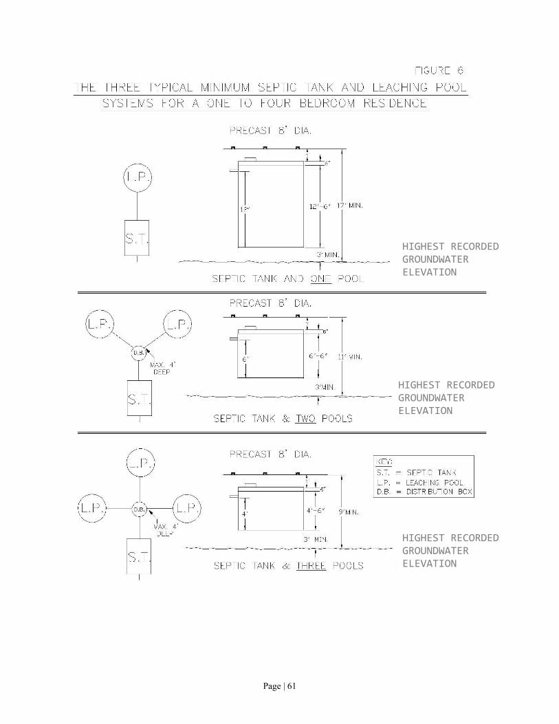
Page | 61
Page | 43
HIGHEST RECORDED GROUNDWATER ELEVATION
HIGHEST RECORDED GROUNDWATER ELEVATION
HIGHEST RECORDED GROUNDWATER ELEVATION

Page | 62
FIGURE 7
TYPICAL CONCRETE SAMPLING MANHOLE DETAIL
Page | 54

Page | 63

Page | 64

Page | 65

Page | 66

Page | 67

Page | 68

Page | 69

Page | 70

Page | 71
FIGURE 16 TYPICAL GRAVELLESS TRENCH OPEN-BOTTOM
CHAMBER SECTION DETAILS

Page | 72
FIGURE 17 TYPICAL GRAVELLESS GEOTEXTILE SAND FILTER TRENCH
SECTION DETAILS

Page | 73
FIGURE 18
TYPICAL GRAVELLESS ABSORPTION TRENCH LAYOUT FOR 4-BEDROOMS WITH AN APPLICATION RATE OF 1.2 g/sf/day

Page | 74
FIGURE 19 PSD CROSS SECTION DETAILS

Page | 75
FIGURE 20
PSD CROSS SECTION DETAILS (LONG SIDE)
PSD base
36” to highest expected groundwater elevation

Page | 76
FIGURE 21
TYPICAL SOIL PERCOLATION TEST ARRANGEMENT