standard h-series pump with atex/iecex motor · h-series flameproof proof atex /iecex motors...
TRANSCRIPT
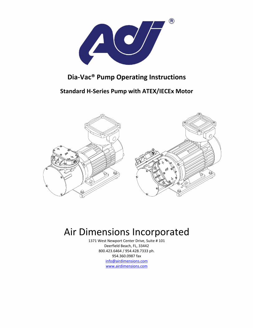
Dia-Vac® Pump Operating Instructions
Standard H-Series Pump with ATEX/IECEx Motor
Air Dimensions Incorporated
1371 West Newport Center Drive, Suite # 101 Deerfield Beach, FL, 33442
800.423.6464 / 954.428.7333 ph. 954.360.0987 fax
[email protected] www.airdimensions.com
2
General Operating Conditions
The H-Series flameproof proof ATEX/IECEx motors utilized on the pump are CE approved ATEX/IECEx Certified EExd IIC T4 IP65. Dia-Vac® Pumps are intended for use with gases only, do not use this product for liquids. For applications where liquid may be present in the gas stream, mount the pump so that the discharge port faces toward the ground. Mounting the pump at the highest point in the system will prevent liquid from collecting in the pump head. An elevated or steam trace heated head pump may be required to maintain the gas temperature through the head. This pump operates at 115/230 VAC 50/60 Hz depending on the motor. See motor label for wiring diagrams and full electrical data. The Dia-Vac® Pump normally runs warm. It is not an indication of trouble if the outer surfaces of the pump or motor are hot to the touch. The Dia-Vac® Pump normally runs quietly, especially when both pressure and vacuum ports are connected into a closed system. An obvious knock or rattle could indicate a problem. Check through "Troubleshooting" with particular attention to the tightness of all screw fasteners. Ambient temperature during the operation of this pump should not exceed 40 °C or 104 °F.
Safety
Before running the pump, ensure that it is properly rated for the environment in which it is located. The H-Series flameproof proof ATEX/IECEx motors utilized on the pump are CE approved ATEX/IECEx Certified EExd IIC T4 IP65. All system components connected the Dia-Vac® Pump must be capable of handling its performance. Ensure that safety regulations are observed when connecting the pump to the electric supply. The connections are to be made in such a way that contact by any object or person with a live wire is impossible. The supply voltage must not vary more than ± 10% of the voltage shown on the motor plate. All proper precautions for the controlled vapor must be observed, and followed. Proper wetted materials for handling corrosive, reactive gasses, or heated must be used. This Dia-Vac® Pump is thermally protected; when the temperature of the pump exceeds the maximum operating temperature, pump operation will be interrupted by the thermal switch. The pump will restart automatically after cooling to acceptable temperatures. Be sure to take necessary precautions to avoid injury during restart.
Operation
No oiling or other lubrication addition is necessary with a Dia-Vac® pump.
3
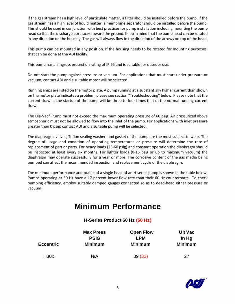
If the gas stream has a high level of particulate matter, a filter should be installed before the pump. If the gas stream has a high level of liquid matter, a membrane separator should be installed before the pump. This should be used in conjunction with best practices for pump installation including mounting the pump head so that the discharge port faces toward the ground. Keep in mind that the pump head can be rotated in any direction on the housing. The gas will always flow in the direction of the arrows on top of the head. This pump can be mounted in any position. If the housing needs to be rotated for mounting purposes, that can be done at the ADI facility. This pump has an ingress protection rating of IP 65 and is suitable for outdoor use. Do not start the pump against pressure or vacuum. For applications that must start under pressure or vacuum, contact ADI and a suitable motor will be selected. Running amps are listed on the motor plate. A pump running at a substantially higher current than shown on the motor plate indicates a problem, please see section “Troubleshooting” below. Please note that the current draw at the startup of the pump will be three to four times that of the normal running current draw. The Dia-Vac® Pump must not exceed the maximum operating pressure of 60 psig. Air pressurized above atmospheric must not be allowed to flow into the inlet of the pump. For applications with inlet pressure greater than 0 psig; contact ADI and a suitable pump will be selected. The diaphragm, valves, Teflon sealing washer, and gasket of the pump are the most subject to wear. The degree of usage and condition of operating temperatures or pressure will determine the rate of replacement of part or parts. For heavy loads (25-60 psig) and constant operation the diaphragm should be inspected at least every six months. For lighter loads (0-15 psig or up to maximum vacuum) the diaphragm may operate successfully for a year or more. The corrosive content of the gas media being pumped can affect the recommended inspection and replacement cycle of the diaphragm. The minimum performance acceptable of a single head of an H-series pump is shown in the table below. Pumps operating at 50 Hz have a 17 percent lower flow rate than their 60 Hz counterparts. To check pumping efficiency, employ suitably damped gauges connected so as to dead-head either pressure or vacuum.
H-Series Product 60 Hz (50 Hz)
Max Press Open Flow Ult VacPSIG LPM In Hg
Eccentric Minimum Minimum Minimum
H30x N/A 39 (33) 27
Minimum Performance
4
NOTE: Check each separately, one or the other port must be open during this test. Use a 0-30 inch Hg vacuum gauge, (or mercury manometer.)
Troubleshooting
This section lists common problems that occur, lists possible causes and the most common fixes. If the problem persists, the pump may require inspection at the ADI facility. To have your pump inspected and repaired at the ADI facility please follow the instructions on the ADI website at http://www.airdimensions.com/service/rma/.
Pump draws excessively high current
• Motor is overloaded o Turn off pump o Remove all pressure and vacuum conditions o Restart and test at atmospheric pressure
• Power input is incorrect o Check motor wiring i.e. 115 V vs 230 V wiring o Check power source
Pumps are only rated for ±10% voltage on name plate
Little or no flow is being produced
• Connections or lines are blocked o Remove blockage
• Liquid or foreign debris has collected in the head o Clean out the head, see section “Servicing” o Place pump outlet facing downward
• Diaphragms, or Flapper Valve Gaskets are worn o See section “Servicing”
Pump is rattling or knocking
• Diaphragm plate screw is under torqued o See section “Servicing” for torquing specifications
• Connecting rod cap is too close to one side of housing o Using a screw driver lightly pry the cap away from the side of the housing
and center. A centering tool is available for purchase at ADI.
5
Servicing
Listed below are the two predominant types of maintenance typical for Dia-Vac® Pumps, the servicing of the consumable parts (diaphragm, valves, gasket, and Teflon® washer), and the servicing of the connecting rod. For video instructions on servicing the head and diaphragm visit http://www.airdimensions.com/service/videos/.
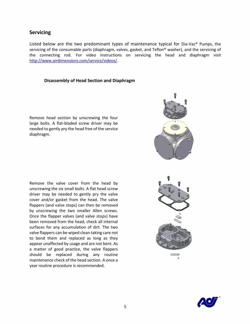
Disassembly of Head Section and Diaphragm
Remove head section by unscrewing the four large bolts. A flat-bladed screw driver may be needed to gently pry the head free of the service diaphragm.
Remove the valve cover from the head by unscrewing the six small bolts. A flat head screw driver may be needed to gently pry the valve cover and/or gasket from the head. The valve flappers (and valve stops) can then be removed by unscrewing the two smaller Allen screws. Once the flapper valves (and valve stops) have been removed from the head, check all internal surfaces for any accumulation of dirt. The two valve flappers can be wiped clean taking care not to bend them and replaced as long as they appear unaffected by usage and are not bent. As a matter of good practice, the valve flappers should be replaced during any routine maintenance check of the head section. A once a year routine procedure is recommended.
6
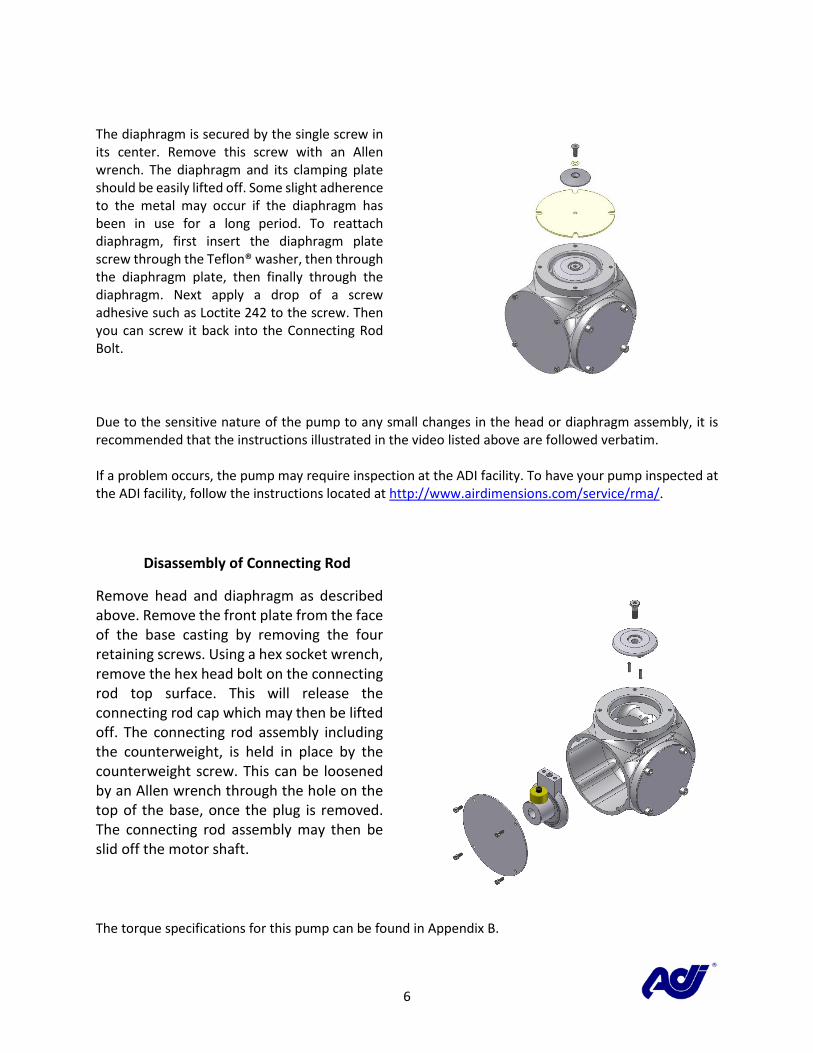
The diaphragm is secured by the single screw in its center. Remove this screw with an Allen wrench. The diaphragm and its clamping plate should be easily lifted off. Some slight adherence to the metal may occur if the diaphragm has been in use for a long period. To reattach diaphragm, first insert the diaphragm plate screw through the Teflon® washer, then through the diaphragm plate, then finally through the diaphragm. Next apply a drop of a screw adhesive such as Loctite 242 to the screw. Then you can screw it back into the Connecting Rod Bolt.
Due to the sensitive nature of the pump to any small changes in the head or diaphragm assembly, it is recommended that the instructions illustrated in the video listed above are followed verbatim. If a problem occurs, the pump may require inspection at the ADI facility. To have your pump inspected at the ADI facility, follow the instructions located at http://www.airdimensions.com/service/rma/.
Disassembly of Connecting Rod
Remove head and diaphragm as described above. Remove the front plate from the face of the base casting by removing the four retaining screws. Using a hex socket wrench, remove the hex head bolt on the connecting rod top surface. This will release the connecting rod cap which may then be lifted off. The connecting rod assembly including the counterweight, is held in place by the counterweight screw. This can be loosened by an Allen wrench through the hole on the top of the base, once the plug is removed. The connecting rod assembly may then be slid off the motor shaft.
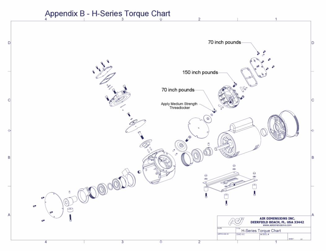
The torque specifications for this pump can be found in Appendix B.
7
If a problem occurs, the pump may require inspection at the ADI facility. To have your pump inspected and repaired at the ADI facility please follow the instructions on the ADI website at http://www.airdimensions.com/service/rma/. Spare Parts
Module Description
11605 KIT, REPAIR – TEFLON®/ EPDM
11611 KIT, REPAIR – ALL TEFLON®
For a complete list of spare parts please follow the following links: Single Head Pump: http://airdimensionscom.c.presscdn.com/wp-content/uploads/2014/11/H301-Fx-GC5_Part2.pdf Double Head Pump: http://airdimensionscom.c.presscdn.com/wp-content/uploads/2014/11/H302-Fx-Fxx_Part2.pdf
Warranty
All Air Dimensions Incorporated Dia-Vac® Pumps are under warranty for 12 months from the ship date. The warranty does not cover consumable parts (diaphragm, valves, gasket, and Teflon® washer). For complete terms and conditions please see Appendix D.
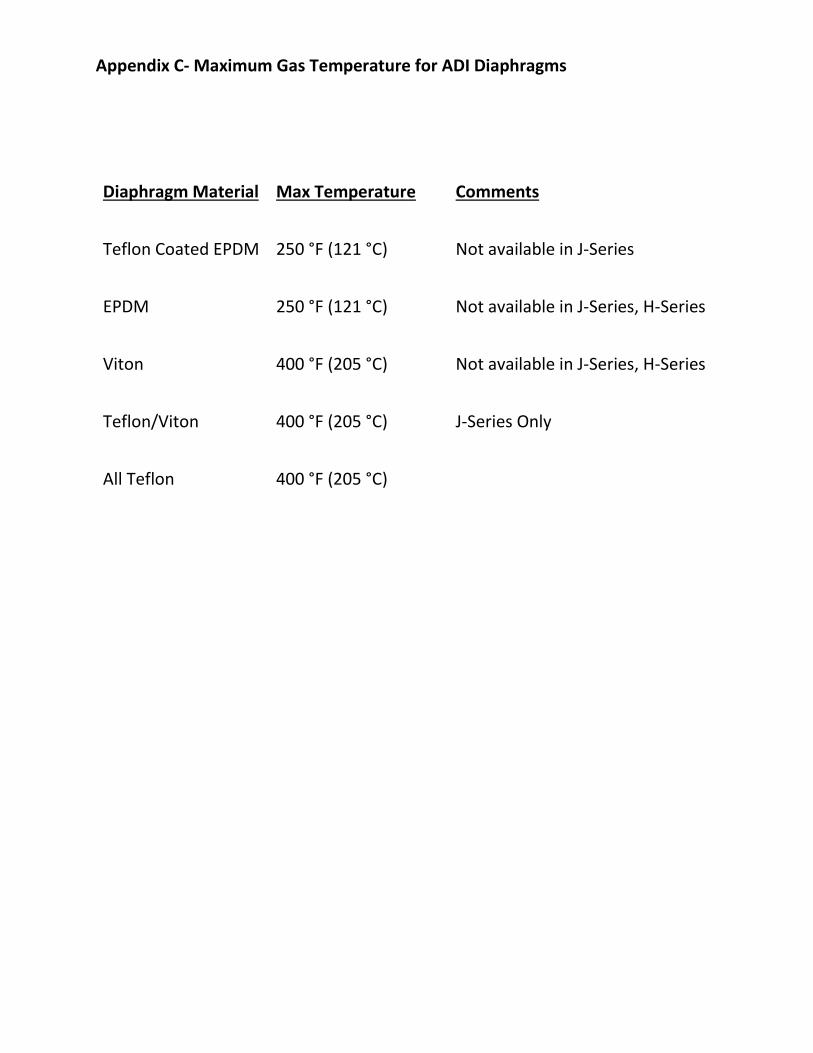
Appendix C- Maximum Gas Temperature for ADI Diaphragms
Diaphragm Material Max Temperature Comments
Teflon Coated EPDM 250 °F (121 °C) Not available in J-Series
EPDM 250 °F (121 °C) Not available in J-Series, H-Series
Viton 400 °F (205 °C) Not available in J-Series, H-Series
Teflon/Viton 400 °F (205 °C) J-Series Only
All Teflon 400 °F (205 °C)
11
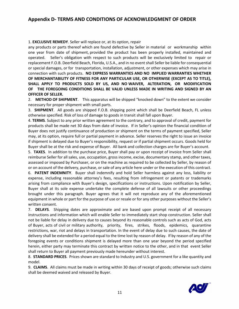
Appendix D- TERMS AND CONDITIONS OF ACKNOWLEDGMENT OF ORDER
1. EXCLUSIVE REMEDY. Seller will replace or, at its option, repair any products or parts thereof which are found defective by Seller in material or workmanship within one year from date of shipment, provided the product has been properly installed, maintained and operated. Seller's obligation with respect to such products will be exclusively limited to repair or replacement F.O.B. Deerfield Beach, Florida, U.S.A., and in no event shall Seller be liable for consequential or special damages, or for transportation, installation, adjustment, or other expenses which may arise in connection with such products. NO EXPRESS WARRANTIES AND NO IMPLIED WARRANTIES WHETHER OF MERCHANTABILITY OF FITNESS FOR ANY PARTICULAR USE, OR OTHERWISE (EXCEPT AS TO TITLE), SHALL APPLY TO PRODUCTS SOLD BY US, AND NO WAIVER, ALTERATION, OR MODIFICATION OF THE FOREGOING CONDITIONS SHALL BE VALID UNLESS MADE IN WRITING AND SIGNED BY AN OFFICER OF SELLER. 2. METHOD OF SHIPMENT. This apparatus will be shipped “knocked down” to the extent we consider necessary for proper shipment with small parts. 3. SHIPMENT. All goods are shipped F.O.B. shipping point which shall be Deerfield Beach, FL unless otherwise specified. Risk of loss of damage to goods in transit shall fall upon Buyer. 4. TERMS. Subject to any prior written agreement to the contrary, and to approval of credit, payment for products shall be made net 30 days from date of invoice. If in Seller’s opinion the financial condition of Buyer does not justify continuance of production or shipment on the terms of payment specified, Seller may, at its option, require full or partial payment in advance. Seller reserves the right to issue an invoice if shipment is delayed due to Buyer’s responsibility, request or if partial shipment occurs. Goods held for Buyer shall be at the risk and expense of Buyer. All bank and collection charges are for Buyer’s account. 5. TAXES. In addition to the purchase price, Buyer shall pay or upon receipt of invoice from Seller shall reimburse Seller for all sales, use, occupation, gross income, excise, documentary stamp, and other taxes, assessed or imposed by Purchaser, or on the machine as required to be collected by Seller, by reason of or on account of the delivery, purchase, or sale of any article here under or the execution of this contract. 6. PATENT INDEMNITY. Buyer shall indemnify and hold Seller harmless against any loss, liability or expense, including reasonable attorney’s fees, resulting from infringement or patents or trademarks arising from compliance with Buyer’s design, specifications or instructions. Upon notification by Seller, Buyer shall at its sole expense undertake the complete defense of all lawsuits or other proceedings brought under this paragraph. Buyer agrees that it will not reproduce any of the aforementioned equipment in whole or part for the purpose of use or resale or for any other purposes without the Seller’s written consent. 7. DELAYS. Shipping dates are approximate and are based upon prompt receipt of all necessary instructions and information which will enable Seller to immediately start shop construction. Seller shall not be liable for delay in delivery due to causes beyond its reasonable controls such as acts of God, acts of Buyer, acts of civil or military authority, priority, fires, strikes, floods, epidemics, quarantine restrictions, war, riot and delays in transportation. In the event of delay due to such causes, the date of delivery shall be extended for a period equal to the time lost by reason of delay. If by reason of any of the foregoing events or conditions shipment is delayed more than one year beyond the period specified herein, either party may terminate this contract by written notice to the other, and in that event Seller shall return to Buyer all payment previously made hereunder without interest. 8. STANDARD PRICES. Prices shown are standard to Industry and U.S. government for a like quantity and model. 9. CLAIMS. All claims must be made in writing within 30 days of receipt of goods; otherwise such claims shall be deemed waived and released by Buyer.
12
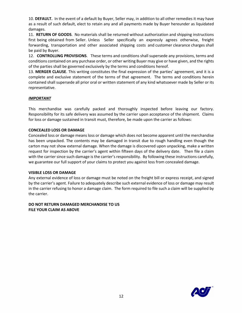
10. DEFAULT. In the event of a default by Buyer, Seller may, in addition to all other remedies it may have as a result of such default, elect to retain any and all payments made by Buyer hereunder as liquidated damages. 11. RETURN OF GOODS. No materials shall be returned without authorization and shipping instructions first being obtained from Seller. Unless Seller specifically an expressly agrees otherwise, freight forwarding, transportation and other associated shipping costs and customer clearance charges shall be paid by Buyer. 12. CONTROLLING PROVISIONS. These terms and conditions shall supersede any provisions, terms and conditions contained on any purchase order, or other writing Buyer may give or have given, and the rights of the parties shall be governed exclusively by the terms and conditions hereof. 13. MERGER CLAUSE. This writing constitutes the final expression of the parties’ agreement, and it is a complete and exclusive statement of the terms of that agreement. The terms and conditions herein contained shall supersede all prior oral or written statement of any kind whatsoever made by Seller or its representative. IMPORTANT This merchandise was carefully packed and thoroughly inspected before leaving our factory. Responsibility for its safe delivery was assumed by the carrier upon acceptance of the shipment. Claims for loss or damage sustained in transit must, therefore, be made upon the carrier as follows: CONCEALED LOSS OR DAMAGE Concealed loss or damage means loss or damage which does not become apparent until the merchandise has been unpacked. The contents may be damaged in transit due to rough handling even though the carton may not show external damage. When the damage is discovered upon unpacking, make a written request for inspection by the carrier’s agent within fifteen days of the delivery date. Then file a claim with the carrier since such damage is the carrier’s responsibility. By following these instructions carefully, we guarantee our full support of your claims to protect you against loss from concealed damage. VISIBLE LOSS OR DAMAGE Any external evidence of loss or damage must be noted on the freight bill or express receipt, and signed by the carrier’s agent. Failure to adequately describe such external evidence of loss or damage may result in the carrier refusing to honor a damage claim. The form required to file such a claim will be supplied by the carrier. DO NOT RETURN DAMAGED MERCHANDISE TO US FILE YOUR CLAIM AS ABOVE