ssc series salt chlorinator user manual · 103 4 6 spring 12 89380216 ssc50 pcb control complete 1...
TRANSCRIPT

EMSW16030450
SSC SERIESSALT CHLORINATOR
USER MANUAL
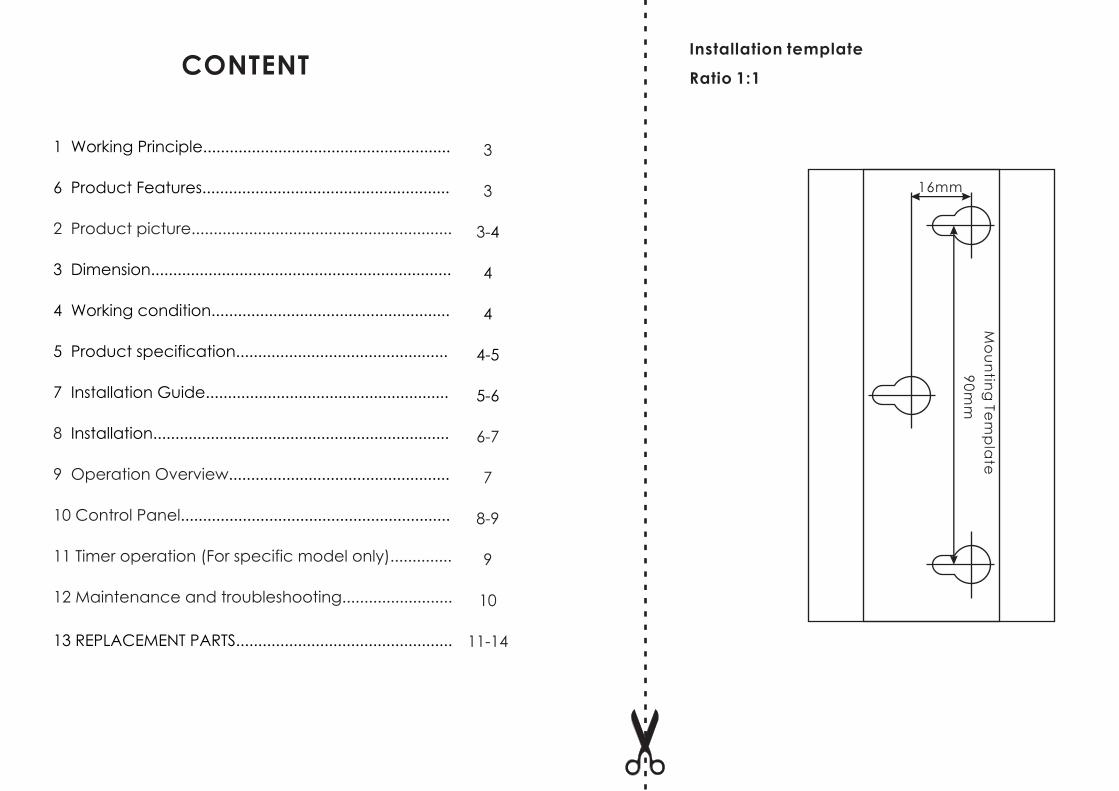
Installation template
Ratio 1:1
90
mm
Mo
un
ting
Tem
pla
te
16mm
1 Working Principle........................................................
6 Product Features........................................................
3 Dimension....................................................................
4 Working condition......................................................
5 Product specification................................................
7 Installation Guide.......................................................
Installation...................................................................
..................................................
.............................................................
2 Product picture...........................................................
8
9 Operation Overview
10 Control Panel
11 Timer operation (For specific model only)..............
12 Maintenance and troubleshooting.........................
3
3
3-
6-7
7
8-9
9
10
11-14
4
4
4
4-5
5-6
CONTENT
13 REPLACEMENT PARTS.................................................
3
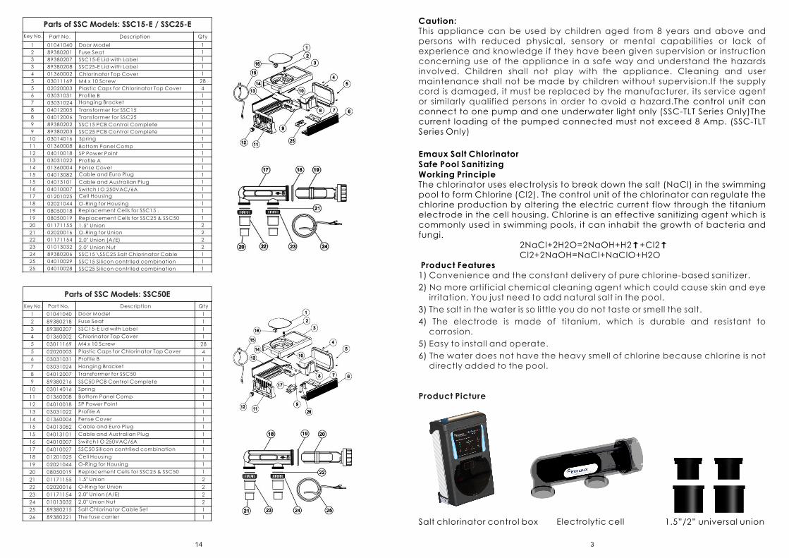
Salt chlorinator control box Electrolytic cell 1.5”/2” universal union
Emaux Salt ChlorinatorSafe Pool SanitizingWorking PrincipleThe chlorinator uses electrolysis to break down the salt (NaCl) in the swimming pool to form Chlorine (Cl2). The control unit of the chlorinator can regulate the chlorine production by altering the electric current flow through the titanium electrode in the cell housing. Chlorine is an effective sanitizing agent which is commonly used in swimming pools, it can inhabit the growth of bacteria and fungi.
2NaCl+2H2O=2NaOH+H2↑+Cl2↑Cl2+2NaOH=NaCl+NaClO+H2O
Product Features1)
2)
3)
4)
5)
6)
Convenience and the constant delivery of pure chlorine-based sanitizer.
No more artificial chemical cleaning agent which could cause skin and eye irritation. You just need to add natural salt in the pool.
The salt in the water is so little you do not taste or smell the salt.
The electrode is made of titanium, which is durable and resistant to corrosion.
Easy to install and operate.
The water does not have the heavy smell of chlorine because chlorine is not directly added to the pool.
Caution:
The control unit can connect to one pump and one underwater light only (SSC-TLT Series Only)The current loading of the pumped connected must not exceed 8 Amp. (SSC-TLT Series Only)
This appliance can be used by children aged from 8 years and above and persons with reduced physical, sensory or mental capabilities or lack of experience and knowledge if they have been given supervision or instruction concerning use of the appliance in a safe way and understand the hazards involved. Children shall not play with the appliance. Cleaning and user maintenance shall not be made by children without supervision.If the supply cord is damaged, it must be replaced by the manufacturer, its service agent or similarly qualified persons in order to avoid a hazard.
Product Picture
14
Key No. Part No. Description Qty
1 01041040 Door Model 1
2 89380201 Fuse Seat 1
3 89380207 SSC15-E Lid with Label 1
3 89380208 SSC25-E Lid with Label 1
4 01360002 Chlorinator Top Cover 1
5 03011169 M4 x 10 Screw 28
5 02020003 Plastic Caps for Chlorinator Top Cover 4
6 03031031 Profile B 1
7 03031024 Hanging Bracket 1
8 04012005 Transformer for SSC15 1
8 04012006 Transformer for SSC25 1
9 89380202 SSC15 PCB Control Complete 1
9 89380203 SSC25 PCB Control Complete 1
10 03014016 Spring 1
11 01360008 Bottom Panel Comp 1
12 04010018 SP Power Point 1
13 03031022 Profile A 1
14 01360004 Fense Cover 1
15 04013082 Cable and Euro Plug 1
15 04013101 Cable and Australian Plug 1
16 04010007 Switch I O 250VAC/6A 1
17 01201025 Cell Housing 1
18 02021044 O-Ring for Housing 1
19 08050018 Replacement Cells for SSC15 . 1
19 08050019 Replacement Cells for SSC25 & SSC50 1
20 01171155 1.5" Union 2
21 02020016 O-Ring for Union 2
22 01171154 2.0" Union (A/E) 2
23 01013032 2.0" Union Nut 2
24 89380206 SSC15 \SSC25 Salt Chlorinator Cable 1
25 04010029 SSC15 Silicon contrlled combination 1
25 04010028 SSC25 Silicon contrlled combination 1
Parts of SSC Models: SSC15-E / SSC25-E
Key No. Part No. Description Qty
1 01041040 Door Model 1
2 89380218 Fuse Seat 1
3 89380207 SSC15-E Lid with Label 1
4 01360002 Chlorinator Top Cover 1
5 03011169 M4 x 10 Screw 28
5 02020003 Plastic Caps for Chlorinator Top Cover 4
6 03031031 Profile B 1
7 03031024 Hanging Bracket 1
8 04012007 Transformer for SSC50 1
9 89380216 SSC50 PCB Control Complete 1
10 03014016 Spring 1
11 01360008 Bottom Panel Comp 1
12 04010018 SP Power Point 1
13 03031022 Profile A 1
14 01360004 Fense Cover 1
15 04013082 Cable and Euro Plug 1
15 04013101 Cable and Australian Plug 1
16 04010007 Switch I O 250VAC/6A 1
17 04010027 SSC50 Silicon contrlled combination 1
18 01201025 Cell Housing 1
19 02021044 O-Ring for Housing 1
20 08050019 Replacement Cells for SSC25 & SSC50 1
21 01171155 1.5" Union 2
22 02020016 O-Ring for Union 2
23 01171154 2.0" Union (A/E) 2
24 01013032 2.0" Union Nut 2
25 89380215 Salt Chlorinator Cable Set 1
26 89380221 The fuse carrier 1
Parts of SSC Models: SSC50E

4
Product Dimension!
! Electrolytic cell: 380 x 118 x 130 mm
Working Condition! Humdity: ≦ 85%! Installation Area must be with good ventilation! Keep away from other heat source
Chlorine Level CalculationRequired Chlorine Production Rate (g/hr) =
Standard Chlorine Level not less than 2mg/litre = 0.002g/litre
Example:Pool Volume: 65m3 = 65,000litre
Turnover Rate: 4 Hour
Required Chlorine Production Rate (g/hr) = =32.5 g/hr
Product Specification:SSC-TLT Series (Chlorinator with underwater light, transformer and time switch)
Control Box: 360 x 220 x 135 mm
65,000 litre X 0.002 g/litre
4 Hours
Pool volume (litre) x Standard Chlorine (g/litre)
Turnover Rate (hr)
Salt chlorinator voltage input/ freq
Rating (salt chlorinatorand underwaterlight transformer)
Model
50000
75000
45000
70000
FiberglassPool (Litre)
CellOutput
Concrete Pool
(Litre)
Cables Screw and fuse Manual
SSC15-TLT
220-250VAC 50/60Hz
100-120VAC 50/60Hz
220-250VAC 50/60Hz
100-120VAC 50/60Hz
100VA+100VA
(underwater light)
100VA+160VA
(underwater light)
15g/hr
25g/hrSSC25-TLT
13
Key No.
Part No. Description Qty
1 01041040 Door Model 1
2 89380218 Fuse Seat 1
3 04010006 Switch I O II 250VAC / 6A 1
4 04010043 Time Analogue Battery Pack 1
5 89380210 SSC50-T Lid with Label 1
6 01360002 Chlorinator Top Cover 1
7 03011169 M4 x 10 Screw 28
7 02020003 Plastic Caps for Chlorinator Top Cover 4
8 03031031 Profile B 1
9 03031024 Hanging Bracket 1
10 04012007 Transformer for SSC50 1
11 03014016 Spring 1
12 89380216 SSC50 PCB Control Complete 1
13 04010027 SSC50 Silicon contrlled combination 1
14 89380217 EMC Board (without Light) 1
15 01360005 Bottom Panel Comp 1
16 04010018 SP Power Point 1
17 89380205 Component Enclosure Plate 1
18 03031022 Profile A 1
19 01360004 Fense Cover 2
20 04013082 Cable and Euro Plug 1
20 04013101 Cable and Australian Plug 1
21 04010015 250V/10A Jack for Australia 1
22 01201025 Cell Housing 1
23 02021044 O-Ring for Housing 1
24 08050019 Replacement Cells for SSC25 & SSC50 1
25 01171155 1.5" Union 2
26 02020016 O-Ring for Union 2
27 01171154 2.0" Union (A/E) 2
28 01013032 2.0" Union Nut 2
29 89380215 Salt Chlorinator Cable Set 1
30 89380221 The fuse carrier 1
Parts of SSC Models: SSC50-T
5
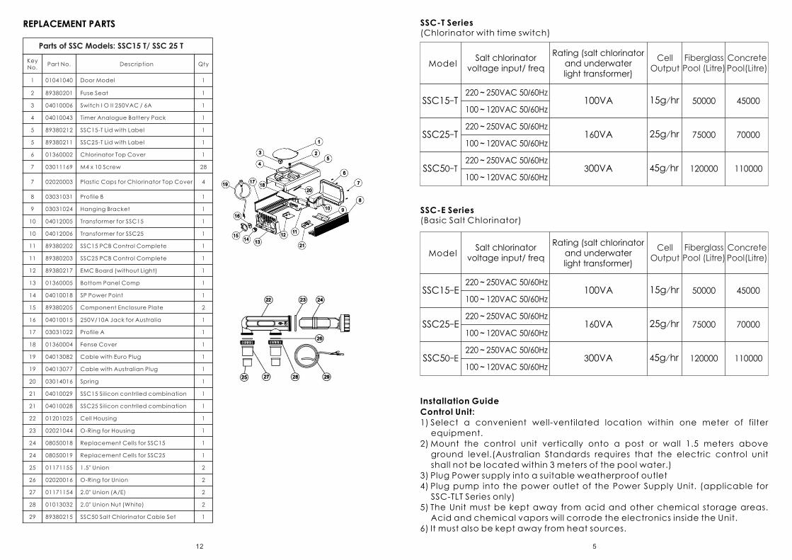
Installation Guide
Control Unit:
1) Select a convenient well-ventilated location within one meter of filter
equipment.
2) Mount the control unit vertically onto a post or wall 1.5 meters above
ground level.(Australian Standards requires that the electric control unit
shall not be located within 3 meters of the pool water.)
3) Plug Power supply into a suitable weatherproof outlet
4) Plug pump into the power outlet of the Power Supply Unit. (applicable for
SSC-TLT Series only)
5) The Unit must be kept away from acid and other chemical storage areas.
Acid and chemical vapors will corrode the electronics inside the Unit.
6) It must also be kept away from heat sources.
SSC15-E
SSC25-E
220~250VAC 50/60Hz
100~120VAC 50/60Hz
220~250VAC 50/60Hz
100~120VAC 50/60Hz
100VA
160VA
15g/hr
25g/hr
SSC50-E220~250VAC 50/60Hz
100~120VAC 50/60Hz300VA 45g/hr
50000 45000
75000 70000
120000 110000
ModelSalt chlorinator
voltage input/ freqCell
OutputFiberglassPool (Litre)
Concrete Pool(Litre)
Rating (salt chlorinatorand underwaterlight transformer)
SSC-T Series(Chlorinator with time switch)
SSC-E Series (Basic Salt Chlorinator)
SSC15-T
SSC25-T
220~250VAC 50/60Hz
100~120VAC 50/60Hz
220~250VAC 50/60Hz
100~120VAC 50/60Hz
100VA
160VA
15g/hr
25g/hr
SSC50-T220~250VAC 50/60Hz
100~120VAC 50/60Hz300VA 45g/hr
50000 45000
75000 70000
120000 110000
ModelSalt chlorinator
voltage input/ freqCell
OutputFiberglassPool (Litre)
Concrete Pool(Litre)
Rating (salt chlorinatorand underwaterlight transformer)
Key No.
Part No. Description Qty
1 01041040 Door Model 1
2 89380201 Fuse Seat 1
3 04010006 Switch I O II 250VAC / 6A 1
4 04010043 Timer Analogue Battery Pack 1
5 89380212 SSC15-T Lid with Label 1
5 89380211 SSC25-T Lid with Label 1
6 01360002 Chlorinator Top Cover 1
7 03011169 M4 x 10 Screw 28
7 02020003 Plastic Caps for Chlorinator Top Cover 4
8 03031031 Profile B 1
9 03031024 Hanging Bracket 1
10 04012005 Transformer for SSC15 1
10 04012006 Transformer for SSC25 1
11 89380202 SSC15 PCB Control Complete 1
11 89380203 SSC25 PCB Control Complete 1
12 89380217 EMC Board (without Light) 1
13 01360005 Bottom Panel Comp 1
14 04010018 SP Power Point 1
15 89380205 Component Enclosure Plate 2
16 04010015 250V/10A Jack for Australia 1
17 03031022 Profile A 1
18 01360004 Fense Cover 1
19 04013082 Cable with Euro Plug 1
19 04013077 Cable with Australian Plug 1
20 03014016 Spring 1
21 04010029 SSC15 Silicon contrlled combination 1
21 04010028 SSC25 Silicon contrlled combination 1
22 01201025 Cell Housing 1
23 02021044 O-Ring for Housing 1
24 08050018 Replacement Cells for SSC15 1
24 08050019 Replacement Cells for SSC25 1
25 01171155 1.5" Union 2
26 02020016 O-Ring for Union 2
27 01171154 2.0" Union (A/E) 2
28 01013032 2.0" Union Nut (White) 2
29 89380215 SSC50 Salt Chlorinator Cable Set 1
Parts of SSC Models: SSC15 T/ SSC 25 T
12
REPLACEMENT PARTS

Electrolytic cell and Electrode
1) The cell must be installed horizontally
2) Connect the water inlet and outlet to the Cell Unit. The water flow direction
must be as indicated on the Cell.
3) To avoid lost of chlorine, the Cell should be installed at the end of the
filtration system, right before the pool water return.
6
Waste
Filter Pump Suction(Water from Pool)
Return to Pool
Pump
Return
Pump Cable
Cell Cable
Cell
PowerSupply
Control Box
Pool LightCable (if fitted)
1.5meter
Pole
Power SupplyControl Box
Pump Cable
Control Box Cable
Cell Cable
Pump
Return
Filter Pump Suction(Water from Pool)
Return to Pool
Cell
SSC-T & SSC-TLT SERIES
SSC-E SERIES
Installation
REPLACEMENT PARTS
Parts of SSC Models: SSC15 TLT/ SSC 25 TLT
Key No.
Part No. Description Qty
1 01041040 Door Model 1
2 89380201 Fuse seat 2
3 04010006 Switch I O II 250VAC / 6A 1
3 04010007 Switch I O 250VAC /6A 1
4 04010043 Timer Analogue Battery Pack 1
5 89380214 SSC15-TLT Lid with Label 1
5 89380213 SSC25-TLT Lid with Label 1
6 01360002 Chlorinator Top Cover 1
7 03011169 M4 x 10 Screw 28
7 02020003 Plastic Caps for Chlorinator Top Cover 4
8 03031031 Profile B 1
9 03031024 Hanging Bracket 1
10 04012005 Transformer for SSC15 1
10 04012006 Transformer for SSC25 1
11 04012008 Transformer for Lighting 1
12 89380202 SSC15 PCB Control Complete 1
12 89380203 SSC25 PCB Control Complete 1
13 89380204 EMC Board (with Light) 1
14 01360005 Bottom Panel Comp 1
15 89380205 Component Enclosure Plate 2
16 04010018 SP Power Point 1
17 04010015 250V/10A Jack for Australia 1
18 04013082 Cable and Euro Plug 1
18 04013101 Cable and Australian Plug 1
19 03031022 Profile A 1
20 01360004 Fense Cover 1
21 03014016 Spring 1
22 01201025 Cell Housing 1
23 02021044 O-Ring for Housing 1
24 08050018 Replacement Cells for SSC15 1
24 08050019 Replacement Cells for SSC25 1
25 01171155 1.5" Union 2
26 02020016 O-Ring for Union 2
27 01171154 2.0" Union (A/E) 2
28 01013032 2.0" Union Nut 2
29 89380206 SSC15 \SSC25 Salt Chlorinator Cable 1
30 04010029 SSC15 Silicon contrlled combination 1
30 04010028 SSC25 Silicon contrlled combination 1
11

7
1) Two self-tapping screws and wall plugs have been provided for fast and simple installation. Simply cut out Template provided for the location of drill entry points. Use a 8mm masonry drill when fitting control unit to a brick or concrete wall. When mounting to a post drill pilot holes and fit screws provided. Once screws are in position simply hang the chlorinator via the bracket on back of Control Box.
2) Glue the salt cell horizontally on the pool return pipe, allow 24 hour curing of the pipe glue.
3) Used the provided cable to connect the control unit and the salt cell together.
IThe single black plug should be connected to the control unit. IThe yellow wire shall be connected to the gas senor of the Cell IThe black wires shall be connected to the electrodes; the connectors may
be fitted either way.
Operation Overview))
)
)
)
1 Power input: 220-240VAC, 50/60Hz2 Recommended pool salt lever: 4000PPM or above (no less than 40kg of pure
salt dissolved in 10,000 liter of pool water)=Run chlorinator at the Salt Levels stated within this document and on the
product to ensure optimum sanitizer output and cell life.=Operating this device at low salt levels will damage the cell and reduce its
life.=The control unit displays a RED indicator when the salt level is low.=If no action is taken to rectify the salt level, damage to the cell may result
which will not be covered under warranty.3 During extreme hot weather conditions or high bather load, the pool water
need to be super-chlorinated using granulated or liquid chlorine or increase the running time of the chlorinator.
4 Always turn down the system control to zero before adding salt, once the salt is completely dissolved, return to the set position.
5 The aluminum casing at the back of the Control Unit acts as a heat sink, do not touch it with bare hands.
Black
Yellow
Black
10
Maintenance and TroubleshootingSalt Chlorinators are a valuable piece of pool sanitizing equipment and must be cared for to get the best performance and life span from it.1) Keep the water chemical balance2) Good operation environment3) Regular check of the titanium plates.During the chlorination process a
white powder Calcium scale may naturally build up on the titanium plates in the cell. Regular monitor of the cell to prevent excessive scale build up. Excessive scale build up will cause damage to your cell, and dramatically reduce its efficiency and lifespan.
4) If the control box failure or calcium excessive build up, maintenance must be carried out by professionals.
5) Avoid any incest from entering the control box, it may damage the electrical component inside.
6) Regular monitor of the filter and pump
Troubleshooting
1) Low/no chlorine production How to handle
- Check the electrical plug/control box/ pump power
- Connect the power properly
- Setting system is too low - Turn the system control to maximum
- Automatically stopped by the timer setting - Adjust the timer setting
- Blown fuse - Cut the power and replace the fuse
- excessive scale build up on the cell - Switch off the salt chlorinator and clean
the salt cell by professional serviceman.
- Filter Backwashing - Once the backwash is complete, turn the filter back to normal filtration
- The gas sensor is not connected - Connect the gas senor according to this manual
- Pump malfunction - Stop the filtration system and repair the pump
- Water temperature too low - Turn on the winter switch
- Salt lever too low - Add salt to the pool
- pH valve too high - Check the water pH valve and keep it around 7.0-7.6
2) No flow
- Pump malfunction - Stop the filtration system and repair the pump
- Filter Backwashing - Once the backwash is complete, turn the filter back to normal filtration
- The gas sensor is not connected - Connect the gas senor according to this manual
3) No display
- Setting system is too low - Turn the system control to maximum

9
SALT CHLORINATOR On/Off/Auto: ON/Off Switch. In Auto mode, the chlorinate
is operated by the timer setting
Light On/Off: Switch for underwater light connected to the control unit (For
certain model)
System Control: Adjust the chlorine product of the chlorinator, for example, for
the control unit turned on for 8 hours
Set at 100% - The salt cell operated at 8 hours
Set at 50% - The salt cell operated at 4 hours
Set at 25% - The salt cell operated at 2 hours
Display: Show the percentage of the chlorine production
Winter Mode Switch and On/ Off LED: Turn on to change the chlorine
production at 85% .
Cell Polarity LED: Show the polarity of the electrodes; the polarity of the
electrode will shifted every 8 hrs of operation, so as to clean the deposition on
the electrode.
Timer: Used to set the program to turn on and off the control unit
automatically. (SSC-T AND SSC-TLT ONLY)
Stand-By LED: Turn on when chlorinate is in stand-by mode, When the
chlorinator is turn on, the standby LED will go off after 35 sec.
No Flow LED: Turn on if there is no water flow, if there is no water flow, the pump
and salt chlorinator will stop automatically.
TIMER OPERATION for SSC-TLT & SSC-T Series Only
1) Turn the outer clock face until the time of
the day is aligned with the clock at the
center of the timer
2) The 24-hour dial has 15 minutes division. The
timer can be programmed by pushing the
captive trippers to the outer ring position
for the entire period that the load is to be
turn ON.
3) The timer clock will rotate with time; the
chlorinator will be turned on automatically
if its captive tripper is pushed outward.
OFFON
ON
SYSTEM-CONTROLMIN MAX
FUSE-250 V F2.5 A
OPERATION
1
2
STAND-BY NO FLOW
WINTER SWITCH
+
-
CELL
OFF
AUTO
FUSE-250 V LIGHT
OFF
LIGHT
ON
Control Panel
OPERATION LEDsFuse:Used to protect the electronic components inside the control unit.Operation LED:There are three status of the operation LED, for example
Status1:Normal Operation
Status2: Low salt level/ Deposition on the electrode/ Low water temperature
Status3:Extremely low salt level/ Serious deposition on the electrode/ Extremely low water temperature
8
OPERATION LEDs
FUSE FOR SALT CHLORINATOR
FUSE FOR LIGHT(SSC-TLT ONLY)
TIMERSSC-TLT ONLY)
(SSC-T AND
CELL POLARITY
WINTER MODE SWITCH
ON/OFF FOR WINTER MODE
LIGHT(SSC-T AND SSC-TLT ONLY)
1
2
Operation
1
2
Operation
1
2
Operation
DISPLAY
ON/OFF BUTTON FOR SALT CHLORINATOR
SYSTEM CONTROL
(Green)
(Green)
(Green)
(Red)
(Red)
(Red)