srd998 intelligent positioner with hart...
TRANSCRIPT
Product Specifications 08.2016 -v4 PSS EVE0108 A-(en)
MAIN FEATURES
Intelligent • Auto-start with self-calibration
• Self diagnostics, status- and diagnostic messages
• Easy local operation with the rotary selector
• Extra-large Multi-Lingual full text graphical LCD • VALcare™ DTM with comprehensive data for
fast configuration• With HART 7 communication
• Stroke 8 to 260 mm (0.3 to 10.2 in) with standardlever; larger stroke with special lever
• Angle range up to 95 ° angle• Mounting onto any linear or rotary actuator• Supply air pressure up to 6 bar (90 psig)• Single or double-acting• Protection class IP 66 and NEMA 4X• Explosion protection: Intrinsic Safety according to
ATEX / IECEx, INMETRO, NEPSI, ...
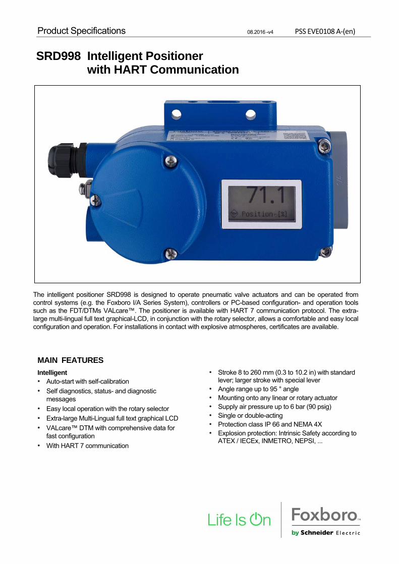
SRD998 Intelligent Positioner with HART Communication
The intelligent positioner SRD998 is designed to operate pneumatic valve actuators and can be operated from control systems (e.g. the Foxboro I/A Series System), controllers or PC-based configuration- and operation tools such as the FDT/DTMs VALcare™. The positioner is available with HART 7 communication protocol. The extra-large multi-lingual full text graphical-LCD, in conjunction with the rotary selector, allows a comfortable and easy local configuration and operation. For installations in contact with explosive atmospheres, certificates are available.

2 SRD998 PSS EVE0108 A-(en)
Contents ........................................................ Page
Common technical data for all basic devices ........ 3
• Operation, Diagnostics, Service plug ........................ 6
• Electrical classification ............................................... 9
Extended technical data for basic devices:
• With communication HART ..................................... 10
Contents .......................................................... Page
FUNCTIONAL DESIGNATIONS ................................ 11
MODEL CODES SRD998 ........................................... 12
ACCESSORIES for mounting to the positioner: • Booster • Manifolds • Gauge manifolds .................... 14
ATTACHMENT to actuators...................................... 17
DIMENSIONS ............................................................... 20
PSS EVE0108 A-(en) SRD998 3
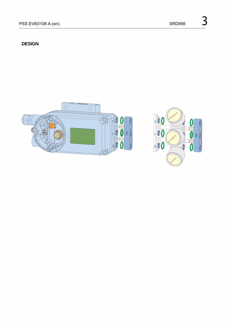
DESIGN
4 SRD998 PSS EVE0108 A-(en)
Supply Supply air pressure ........ 1.4 to 6 bar (20 to 87 psig)
Output to actuator . . . . . . . . . 0 to ~100 % of supply air pressure (up to 5.5 bar at 6 bar supply air pressure)
Air supply . . . . . . . . . . . . . according to ISO 8573-1 - Solid particle size and density class 2 - Oil rate ........................... class 3 - Pressure dew point 10 K under ambient temperature
The use of filter regulator for air supply of positioner is strongly recommended. It reduces the air pressure to actuator’s maximum pressure and keeps it constant. For standard pneumatic flow we recommend the FRS02 (Aluminum) or FRS03 (SS) filter regulator.
Travel range Stroke range .................... 8 to 260 mm (0.3 to 10.2 in)
with standard feedback levers; special levers on request Rotation angle range ......... up to 95 °angle
without mechanical stop
Response characteristic 1) 2)
Sensitivity . . . . . . . . . . . . . . . . . < 0.1 % of travel span Non-linearity (terminal based adjustment) ............ < 0.6 % of travel span Hysteresis ........................ < 0.3 % of travel span Supply air dependence ..... < 0.1 % / 1 bar (15 psi) Temperature effect ........... < 0.3 % / 10 K Mechanical vibration effect acc. IEC 60068-2-6 (2007) for 10 to 500 Hz up to 2 g. .
For Pneumatcs B0S ..... < 0.25% up to 80 Hz and 1 g < 0.25% up to 70 Hz and 2 g
For Pneumatcs C0S ..... < 0.25% up to 400 Hz and 1 g < 0.25% up to 70 Hz and 2 g
In case of high vibrations we recommend using remote mounting solution. 1) Data measured according to VDI/VDE 2177 and IEC 61514-2 2) With 90° angle, rotary actuator 3) Measured according ANSI / ISA-75.13.01-2013
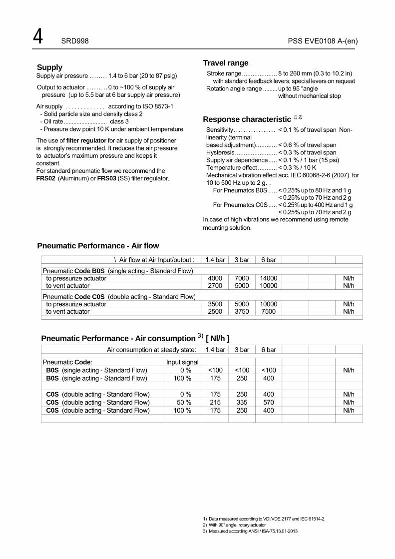
Pneumatic Performance - Air flow
\ Air flow at Air Input/output : 1.4 bar 3 bar 6 bar
Pneumatic Code B0S (single acting - Standard Flow)to pressurize actuator 4000 7000 14000 Nl/hto vent actuator 2700 5000 10000 Nl/h
Pneumatic Code C0S (double acting - Standard Flow)to pressurize actuator 3500 5000 10000 Nl/hto vent actuator 2500 3750 7500 Nl/h
Pneumatic Performance - Air consumption 3) [ Nl/h ]
Air consumption at steady state: 1.4 bar 3 bar 6 bar
Pneumatic Code: Input signal B0S (single acting - Standard Flow) 0 % <100 <100 <100 Nl/h B0S (single acting - Standard Flow) 100 % 175 250 400
C0S (double acting - Standard Flow) 0 % 175 250 400 Nl/h C0S (double acting - Standard Flow) 50 % 215 335 570 Nl/h C0S (double acting - Standard Flow) 100 % 175 250 400 Nl/h

PSS EVE0108 A-(en) SRD998 5
�
���
� � �
�
� � � � � � � ��
� � � � � � � � � � � � �
� � � �
� � � � �
� � � �
��
�
�
BOOSTERS for increased air flow
Volume Booster Series (to order as accessory) For large actuators or to reduce action time, a volume booster may be necessary.
VBS100 / VBS110 Volume boosters with Cv1 and pneumatic connection 1/4”, for remote mounting VBS100 in Aluminum, VBS110 in Stainless Steel 316
For more information please consult PSS EVE0601.
VBS300 / VBS310 Volume boosters with Cv 7 and pneumatic connection 1’’, for remote mounting VBS300 in Aluminum, VBS310 in Stainless Steel 316
For more information please consult PSS EVE0603.
Examples for mounting
� � � � �
�� � � �
� � � �
� � � �
����
6 SRD998 PSS EVE0108 A-(en)
FUNCTIONAL SPECIFICATIONS
Features Automatic start-up .............. (Autostart functionality) Automatic determination of the mechanical end positions of the valve (initial value and final value), IP motor parameters, direction of action of the spring and control parameters. The control parameters are optimized dynamically during this routine. This procedure makes a perfect adjustment and opti- mization to the actuator possible without additional manual settings! Several autostart modes are available (details see on next pages).
Operation and Configuration The local LCD enable a fast and easy configuration as well as clear diagnostic messages. Local .................................. with local rotary selector Display............................... multi-lingual graphic LCD
The positioner contains following menu languages: • English • German • French • Chinese • Portuguese • Spanish ...

PSS EVE0108 A-(en) SRD998 7
Manual local and remote settings: Actuator mode ................... linear or rotary actuator Linear valve .................... left or right mounted Rotary actuator ................. opening clockwise or
counter-clockwise Valve characteristic ........... linear, equal percentage,
invers-equal percentage or custom (22 points)
Valve action ........................ opens or closes with increasing setpoint
Split range ......................... free upper and lower values Travel limits ....................... free upper and lower values Cutoffs .................................. free upper and lower values Stroke range .................... configurable Temperature unit ................ configurable (°C or °F) Autostart .......................... - Endpoints
- Standard Autostart - Enhanced Autostart - Smooth response - Fast response
Control parameters ............ Determined during Autostart. Working range ................... freely adjustable (for
indication on LCD) Manual adjustment of ......... P-gain, I-time, D-time,
T63-time, and dead band Manual operation ................ Manual input of setpoint to
drive the valve in steps of 12.5 % or 1 %
Pneumatic test .................... Function to test the pneumatic output
LCD orientation ................. standard, and upside down
Software supported configurations: - By means of Hand Held Terminal (HART) - PC by means of VALcare DTM Software - I/A Series System, Foxboro Evo and other DCSs
Failure handling In case of Single Acting, Safety position at - Air supply failure ................ pressure y1 = zero - Electric power failure ........ pressure y1 = zero - Failure of electronics ........ pressure y1 = zero
In case of Double Acting or spool valve amplifier, safety position at - Air supply failure ............... pressure y1 = zero;
y2 =zero - Electric power failure ........ pressure y1 = zero;
y2 = full air supply pressure - Failure of electronics ....... pressure y1 = zero;
y2 = full air supply pressure
8 SRD998 PSS EVE0108 A-(en)
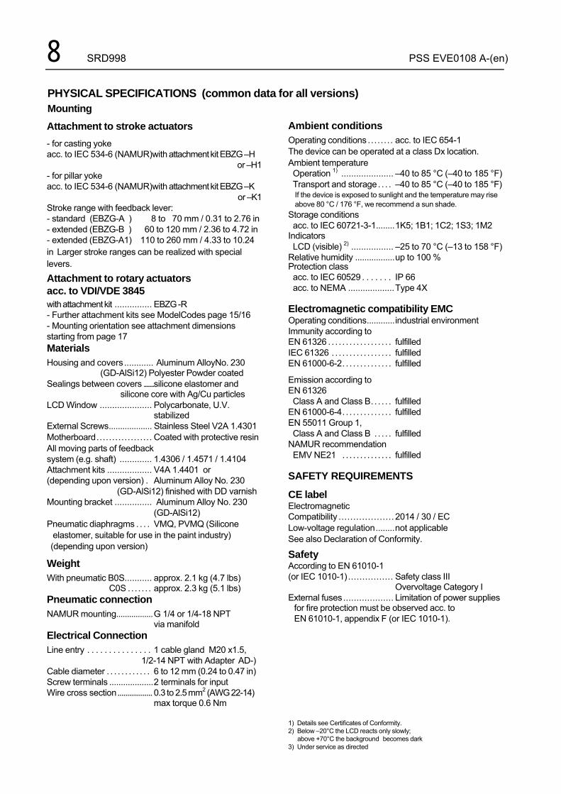
Attachment to stroke actuators
- for casting yoke acc. to IEC 534-6 (NAMUR)with attachment kit EBZG –H
or –H1 - for pillar yoke acc. to IEC 534-6 (NAMUR)with attachment kit EBZG –K
or –K1 Stroke range with feedback lever: - standard (EBZG-A ) 8 to 70 mm / 0.31 to 2.76 in - extended (EBZG-B ) 60 to 120 mm / 2.36 to 4.72 in - extended (EBZG-A1) 110 to 260 mm / 4.33 to 10.24 in Larger stroke ranges can be realized with special levers.
Attachment to rotary actuators acc. to VDI/VDE 3845 with attachment kit ............... EBZG -R - Further attachment kits see ModelCodes page 15/16 - Mounting orientation see attachment dimensions starting from page 17 Materials Housing and covers ............ Aluminum AlloyNo. 230
(GD-AlSi12) Polyester Powder coated Sealings between covers ........ silicone elastomer and
silicone core with Ag/Cu particles LCD Window ..................... Polycarbonate, U.V.
stabilized External Screws ................... Stainless Steel V2A 1.4301 Motherboard .................. Coated with protective resin All moving parts of feedback system (e.g. shaft) ............. 1.4306 / 1.4571 / 1.4104 Attachment kits .................. V4A 1.4401 or (depending upon version) . Aluminum Alloy No. 230
(GD-AlSi12) finished with DD varnish Mounting bracket ............... Aluminum Alloy No. 230
(GD-AlSi12) Pneumatic diaphragms . . . . VMQ, PVMQ (Silicone elastomer, suitable for use in the paint industry) (depending upon version)
Weight With pneumatic B0S........... approx. 2.1 kg (4.7 lbs) C0S . . . . . . . approx. 2.3 kg (5.1 lbs) Pneumatic connection NAMUR mounting................. G 1/4 or 1/4-18 NPT
via manifold Electrical Connection Line entry . . . . . . . . . . . . . . . 1 cable gland M20 x1.5, 1/2-14 NPT with Adapter AD-) Cable diameter . . . . . . . . . . . . 6 to 12 mm (0.24 to 0.47 in) Screw terminals ................... 2 terminals for input Wire cross section .................. 0.3 to 2.5 mm2 (AWG 22-14)
max torque 0.6 Nm
Ambient conditions Operating conditions ........ acc. to IEC 654-1 The device can be operated at a class Dx location. Ambient temperature Operation 1) ..................... –40 to 85 °C (–40 to 185 °F) Transport and storage . . . . –40 to 85 °C (–40 to 185 °F)
If the device is exposed to sunlight and the temperature may rise above 80 °C / 176 °F, we recommend a sun shade.
Storage conditions acc. to IEC 60721-3-1 ........ 1K5; 1B1; 1C2; 1S3; 1M2 Indicators LCD (visible) 2) ................. –25 to 70 °C (–13 to 158 °F) Relative humidity ................. up to 100 % Protection class acc. to IEC 60529 . . . . . . . IP 66 acc. to NEMA ................... Type 4X Electromagnetic compatibility EMC Operating conditions ............ industrial environment Immunity according to EN 61326 . . . . . . . . . . . . . . . . . . fulfilled IEC 61326 . . . . . . . . . . . . . . . . . fulfilled EN 61000-6-2 . . . . . . . . . . . . . . fulfilled
Emission according to EN 61326 Class A and Class B . . . . . . fulfilled EN 61000-6-4 . . . . . . . . . . . . . . fulfilled EN 55011 Group 1, Class A and Class B . . . . . fulfilled NAMUR recommendation EMV NE21 . . . . . . . . . . . . . . fulfilled SAFETY REQUIREMENTS
CE label Electromagnetic Compatibility ................... 2014 / 30 / EC Low-voltage regulation ........ not applicable See also Declaration of Conformity.
Safety According to EN 61010-1 (or IEC 1010-1) ................ Safety class III
Overvoltage Category I External fuses ................... Limitation of power supplies
for fire protection must be observed acc. to EN 61010-1, appendix F (or IEC 1010-1).
1) Details see Certificates of Conformity. 2) Below –20°C the LCD reacts only slowly; above +70°C the background becomes dark 3) Under service as directed
PHYSICAL SPECIFICATIONS (common data for all versions) Mounting
PSS EVE0108 A-(en) SRD998 9
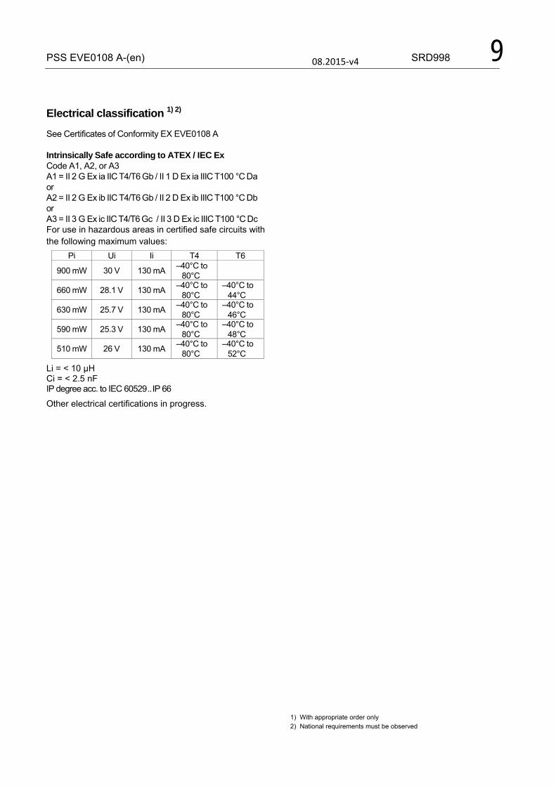
Electrical classification 1) 2)
See Certificates of Conformity EX EVE0108 A Intrinsically Safe according to ATEX / IEC Ex Code A1, A2, or A3 A1 = II 2 G Ex ia IIC T4/T6 Gb / II 1 D Ex ia IIIC T100 °C Da or A2 = II 2 G Ex ib IIC T4/T6 Gb / II 2 D Ex ib IIIC T100 °C Db or A3 = II 3 G Ex ic IIC T4/T6 Gc / II 3 D Ex ic IIIC T100 °C Dc For use in hazardous areas in certified safe circuits with the following maximum values:
Pi Ui Ii T4 T6
900 mW 30 V 130 mA –40°C to
80°C
660 mW 28.1 V 130 mA –40°C to
80°C –40°C to
44°C
630 mW 25.7 V 130 mA –40°C to
80°C –40°C to
46°C
590 mW 25.3 V 130 mA –40°C to
80°C –40°C to
48°C
510 mW 26 V 130 mA –40°C to
80°C –40°C to
52°C
Li = < 10 μH Ci = < 2.5 nF IP degree acc. to IEC 60529 .. IP 66
Other electrical certifications in progress.
1) With appropriate order only 2) National requirements must be observed
08.2015-v4

10 SRD998 PSS EVE0108 A-(en) SRD998 with HART communication SRD998-Hxxxx
Signal Input .................................. Two wire system Reverse polarity protection. standard feature Signal range ..................... 4 to 20 mA Operating range. ............... 3.6 to 21.5 mA Input voltage ..................... DC 12...36 V 1) (unloaded) Load ................................. 420 Ohms, 8.4 V at 20 mA Communication signal ......... HART 7, 1200 Baud, FSK
(Frequency Shift Key) modulated on 4 to 20 mA 0.5 Vpp at 1 kOhm load
Input impedance Zi . . . . . . . Z = 320 Ohms for ac voltage 0.5 to 10 kHz with < 3 dB non-linearity Cable capacity and inductance see HART standard specifications (e.g. C < 100 nF). Impedance of other devices at the input (parallel or serial) must be within HART spec. Applications without communication require not to exceed input capacitance parallel to the input not higher than 5 μF. Start-up time ................... approx. 3 sec Interruption time without power down . . . typ. 8 ms 2)
1) On request we can specify higher voltage limits 2) Worst case conditions 4-20 mA, i/p-output with max. current
Configuration The SRD998 can be configured via HART by any host system whatever is a PC with a HART Modem, Hand Held Terminal or a DCS.
LOCAL (by means of rotary selector and LCD display) See page 6
DTM (Device Type Manager) We are a leading company in term of FDT-DTM technology http://www.fdtgroup.org/product-catalog/certified-dtms?c ompany=Foxboro+Eckardt+GmbH&field_device_type_v alue_many_to_one=All&field_protocol_value_many_to_ one=All
Therefore we provide a DTM fully certified for its inter- operability and with the state-of-the-art presentation and diagnostics features. The DTM can be downloaded from our homepage.
DD (Device Description) and EDD (Enhanced Device Description) In case the host system is not supporting the FDT-DTM technology, you can download the DD and/or EDD from our homepage.
PSS EVE0108 A-(en) SRD998 11
�
� �
� � � �
� �
� �
�
�
�
�
� � � �� �
�
� �
� �
�� �
� �
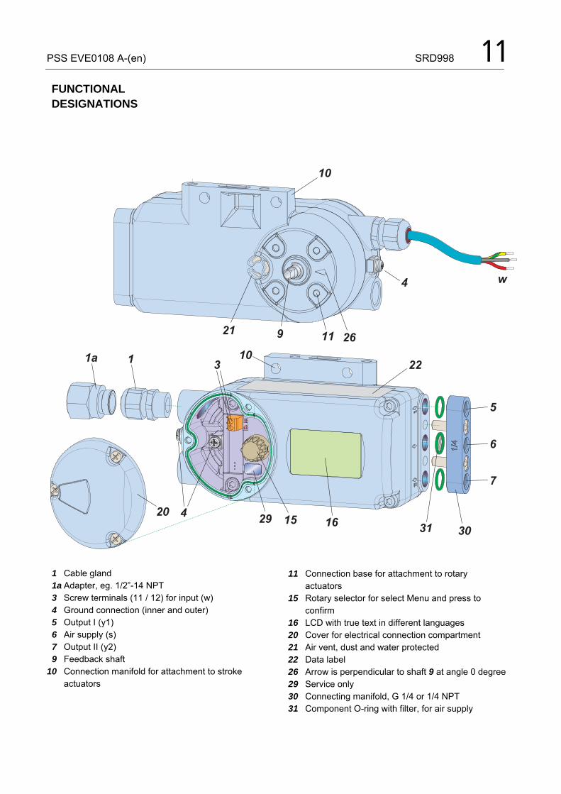
FUNCTIONAL DESIGNATIONS
1 Cable gland 1a Adapter, eg. 1/2”-14 NPT 3 Screw terminals (11 / 12) for input (w) 4 Ground connection (inner and outer) 5 Output I (y1) 6 Air supply (s) 7 Output II (y2) 9 Feedback shaft 10 Connection manifold for attachment to stroke actuators
11 Connection base for attachment to rotary actuators 15 Rotary selector for select Menu and press to confirm 16 LCD with true text in different languages 20 Cover for electrical connection compartment 21 Air vent, dust and water protected 22 Data label 26 Arrow is perpendicular to shaft 9 at angle 0 degree 29 Service only 30 Connecting manifold, G 1/4 or 1/4 NPT 31 Component O-ring with filter, for air supply
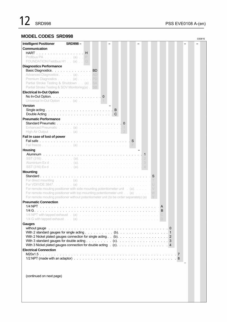
12 SRD998 PSS EVE0108 A-(en) MODEL CODES SRD998
030816
Intelligent Positioner SRD998 –
Communication HART . . . . . . . . . . . . . . . . .Profibus PA . . . . . . . . . . (a) . .FOUNDATION Fieldbus H1 . . (a) . .
H P Q
BDADPDSA SB
. 0 . 1
–
. B
. C
. 0 . 1 . 2
. S
. F
– . 1 . 2 . 3 . 4
. S
. T
. U
. V W
. Y
. A . B
C D
. 0
. 1
. 2
. 3
. 4
. 7 . 8
– –
Diagnostics Performance Basic Diagnostics . . . . . . . . . . . . . . Advanced Diagnostics . . . . . (a) . . . . . Premium Diagnostics . . . . . (a) . . . . . Partial Stroke Testing & Shutdown . . (a) . Partial Stroke Testing & SOV Monitoring(a) .
Electrical In-Out Option No In-Out Option. . . . . . . . . . . . . . . . . Universal In-Out Option . . . . (a) . . . . . . .
Version –Single acting . . . . . . . . . . . . . . . . . . . . . . . Double Acting . . . . . . . . . . . . . . . . . . . . . .
Pneumatic Performance Standard Pneumatic . . . . . . . . . . . . . . . . . . . . . . Enhanced Pneumatic . . . . . (a) . . . . . . . . . . . . . . High Air Output . . . . . . . . (a) . . . . . . . . . . . . . .
Fail in case of lost of power Fail safe . . . . . . . . . . . . . . . . . . . . . . . . . . . . . . . Fail freeze . . . . . . . . . . . (a) . . . . . . . . . . . . . . . . .
Housing –Aluminum . . . . . . . . . . . . . . . . . . . . . . . . . . . . . . . . . . SST (316) . . . . . . . . . . . (a). . . . . . . . . . . . . . . . . . . . . . Aluminium Ex d . . . . . . . . (a). . . . . . . . . . . . . . . . . . . . . . SST (316) Ex d . . . . . . . . (a). . . . . . . . . . . . . . . . . . . . . .
Mounting Standard . . . . . . . . . . . . . . . . . . . . . . . . . . . . . . . . . . . . . . For direct mounting . . . . . . (a). . . . . . . . . . . . . . . . . . . . . . . . . For VDI/VDE 3847 . . . . . . . (a) . . . . . . . . . . . . . . . . . . . . . . . . For remote mouting positioner with side mounting potentiometer unit . (a). . . . . For remote mouting positioner with top mounting potentiometer unit . . (a) . . . . .For remote mouting positioner without potentiometer unit (to be order separately) (a)
Pneumatic Connection 1/4 NPT . . . . . . . . . . . . . . . . . . . . . . . . . . . . . . . . . . . . . . . . . 1/4 G . . . . . . . . . . . . . . . . . . . . . . . . . . . . . . . . . . . . . . . . . . . 1/4 NPT with tapped exhaust . (a) . . . . . . . . . . . . . . . . . . . . . . . . . . . .1/4 G with tapped exhaust . . . (a) . . . . . . . . . . . . . . . . . . . . . . . . . . . .
Gauges without gauge . . . . . . . . . . . . . . . . . . . . . . . . . . . . . . . . . . . . . . . . . With 2 standard gauges for single acting . . . . . . . . . . (b). . . . . . . . . . . . . . . . . With 2 Nickel plated gauges connection for single acting . . (b). . . . . . . . . . . . . . . . . With 3 standard gauges for double acting . . . . . . . . . (c). . . . . . . . . . . . . . . . . With 3 Nickel plated gauges connection for double acting . (c) . . . . . . . . . . . . . . . . .
Electrical Connection M20x1.5 . . . . . . . . . . . . . . . . . . . . . . . . . . . . . . . . . . . . . . . . . . . . . . . 1/2 NPT (made with an adaptor) . . . . . . . . . . . . . . . . . . . . . . . . . . . . . . . . . . .
–
(continued on next page)
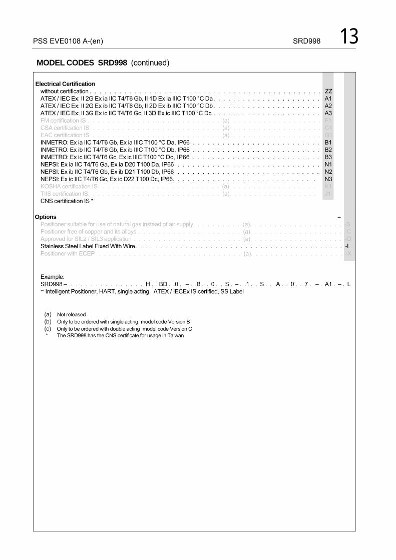
PSS EVE0108 A-(en) SRD998 13 MODEL CODES SRD998 (continued)
Electrical Certification
without certification . . . . . . . . . . . . . . . . . . . . . . . . . . . . . . . . . . . . . . . . . . . . . . . ATEX / IEC Ex: II 2G Ex ia IIC T4/T6 Gb, II 1D Ex ia IIIC T100 °C Da . . . . . . . . . . . . . . . . . . . . . . ATEX / IEC Ex: II 2G Ex ib IIC T4/T6 Gb, II 2D Ex ib IIIC T100 °C Db . . . . . . . . . . . . . . . . . . . . . . ATEX / IEC Ex: II 3G Ex ic IIC T4/T6 Gc, II 3D Ex ic IIIC T100 °C Dc . . . . . . . . . . . . . . . . . . . . . . FM certification IS . . . . . . . . . . . . . . . . . . . . . . . . . . . (a) . . . . . . . . . . . . . . . . . . CSA certification IS . . . . . . . . . . . . . . . . . . . . . . . . . . (a) . . . . . . . . . . . . . . . . . . EAC certification IS . . . . . . . . . . . . . . . . . . . . . . . . . . (a) . . . . . . . . . . . . . . . . . . INMETRO: Ex ia IIC T4/T6 Gb, Ex ia IIIC T100 °C Da, IP66 . . . . . . . . . . . . . . . . . . . . . . . . . . INMETRO: Ex ib IIC T4/T6 Gb, Ex ib IIIC T100 °C Db, IP66 . . . . . . . . . . . . . . . . . . . . . . . . . . INMETRO: Ex ic IIC T4/T6 Gc, Ex ic IIIC T100 °C Dc, IP66 . . . . . . . . . . . . . . . . . . . . . . . . . . NEPSI: Ex ia IIC T4/T6 Ga, Ex ia D20 T100 Da, IP66 . . . . . . . . . . . . . . . . . . . . . . . . . . . . . NEPSI: Ex ib IIC T4/T6 Gb, Ex ib D21 T100 Db, IP66 . . . . . . . . . . . . . . . . . . . . . . . . . . . . . NEPSI: Ex ic IIC T4/T6 Gc, Ex ic D22 T100 Dc, IP66. . . . . . . . . . . . . . . . . . . . . . . . . . . . . KOSHA certification IS. . . . . . . . . . . . . . . . . . . . . . . . . (a) . . . . . . . . . . . . . . . . . TIIS certification IS. . . . . . . . . . . . . . . . . . . . . . . . . . . (a). . . . . . . . . . . . . . . . . . CNS certification IS *
ZZ A1 A2 A3 F1 C1 G1B1 B2 B3 N1 N2 N3 K1 J1
Options – Positioner suitable for use of natural gas instead of air supply . . . . . . . . . (a). . . . . . . . . . . . . . . . . . . -S Positioner free of copper and its alloys . . . . . . . . . . . . . . . . . . . . . (a). . . . . . . . . . . . . . . . . . . -C Approved for SIL2 / SIL3 application . . . . . . . . . . . . . . . . . . . . . . (a). . . . . . . . . . . . . . . . . . . -Q Stainless Steel Label Fixed With Wire . . . . . . . . . . . . . . . . . . . . . . . . . . . . . . . . . . . . . . . . . . -L Positioner with ECEP . . . . . . . . . . . . . . . . . . . . . . . . . . . . . (a). . . . . . . . . . . . . . . . . . . -X
Example: SRD998 – . . . . . . . . . . . . . . . H . . BD . .0 . – . .B . . 0 . . S . – . .1 . . S . . A . . 0 . . 7 . – . A1 . – . L = Intelligent Positioner, HART, single acting, ATEX / IECEx IS certified, SS Label
(a) Not released (b) Only to be ordered with single acting model code Version B (c) Only to be ordered with double acting model code Version C * The SRD998 has the CNS certificate for usage in Taiwan

14 SRD998 PSS EVE0108 A-(en)
� � � �
�
�� � �
�
� � � �
� � � �
�
�
� � � � � �
� � � � � �
�
�
� �
� � � � �
�
�
�
�
�
�
�
�
�
� � � �
Accessories, for all basic devices
no threads O-Ringwith filter
Code A: 3x 1/4-18 NPT Code B: 3x G 1/4 Connection manifold
Sticker closes the unused output at single acting
Boosters for remote mounting:(see extra PSS)
Code 1 or 2, single Connection manifold for single acting positioner with pressure gauges for supply air s and output y
Code 3 or 4, double Connection manifold for double acting positioner with pressure gauges for supply air s, outputs y1 and y2
no threads
no threads
PSS EVE0108 A-(en) SRD998 15 080915
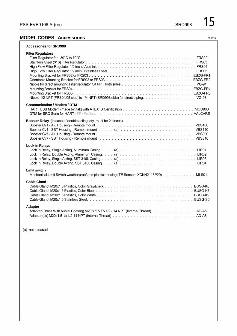
Accessories for SRD998
Filter Regulators Filter Regulator for –30°C to 70°C. . . . . . . . . . . . . . . . . . . . . . . . . . . . . . . . . . . . . . . FRS02 Stainless Steel (316) Filter Regulator . . . . . . . . . . . . . . . . . . . . . . . . . . . . . . . . . . . . . FRS03 High Flow Filter Regulator 1/2 inch / Aluminium . . . . . . . . . . . . . . . . . . . . . . . . . . . . . . . . FRS04 High Flow Filter Regulator 1/2 inch / Stainless Steel. . . . . . . . . . . . . . . . . . . . . . . . . . . . . . FRS05 Mounting Bracket for FRS02 or FRS03 . . . . . . . . . . . . . . . . . . . . . . . . . . . . . . . . . . . EBZG-FR1 Orientable Mounting Bracket for FRS02 or FRS03 . . . . . . . . . . . . . . . . . . . . . . . . . . . . . EBZG-FR2 Nipple for direct mounting Filter regulator 1/4 NPT both sides . . . . . . . . . . . . . . . . . . . . . . . . . VG-91 Mounting Bracket for FRS04 . . . . . . . . . . . . . . . . . . . . . . . . . . . . . . . . . . . . . . . . EBZG-FR4 Mounting Bracket for FRS05 . . . . . . . . . . . . . . . . . . . . . . . . . . . . . . . . . . . . . . . . EBZG-FR5 Nipple 1/2 NPT (FRS04/05 side) to 1/4 NPT (SRD998 side) for direct piping. . . . . . . . . . . . . . . . . . VG-93
Communication / Modem / DTM HART USB Modem (made by Ifak) with ATEX IS Certification . . . . . . . . . . . . . . . . . . . . . . . . MOD900 DTM for SRD Serie for HART / FF / Profibus . . . . . . . . . . . . . . . . . . . . . . . . . . . . . . . . VALCARE
Booster Relay (in case of double acting, qty. must be 2 pieces) Booster Cv1 - Alu Housing - Remote mount . . . . . . . . . . . . . . . . . . . . . . . . . . . . . . . . . VBS100 Booster Cv1 - SST Housing - Remote mount . . . . . (a) . . . . . . . . . . . . . . . . . . . . . . . . . VBS110 Booster Cv7 - Alu Housing - Remote mount . . . . . . . . . . . . . . . . . . . . . . . . . . . . . . . . . VBS300 Booster Cv7 - SST Housing - Remote mount . . . . . . . . . . . . . . . . . . . . . . . . . . . . . . . . VBS310
Lock-in Relays Lock In Relay, Single Acting, Aluminum Casing . . . . (a) . . . . . . . . . . . . . . . . . . . . . . . . . . LIR01 Lock In Relay, Double Acting, Aluminum Casing . . . . (a) . . . . . . . . . . . . . . . . . . . . . . . . . . LIR02 Lock In Relay, Single Acting, SST 316L Casing . . . . (a) . . . . . . . . . . . . . . . . . . . . . . . . . . LIR03 Lock In Relay, Double Acting, SST 316L Casing . . . . (a) . . . . . . . . . . . . . . . . . . . . . . . . . . LIR04
Limit switch Mechanical Limit Switch weatherproof and plastic housing (TE Sensors XCKN2118P20) . . . . . . . . . . . MLS01
Cable Gland Cable Gland, M20x1.5 Plastics, Color Gray/Black . . . . . . . . . . . . . . . . . . . . . . . . . . . . . . BUSG-K6 Cable Gland, M20x1.5 Plastics, Color Blue . . . . . . . . . . . . . . . . . . . . . . . . . . . . . . . . . BUSG-K7 Cable Gland, M20x1.5 Plastics, Color White. . . . . . . . . . . . . . . . . . . . . . . . . . . . . . . . . BUSG-K9 Cable Gland, M20x1.5 Stainless Steel. . . . . . . . . . . . . . . . . . . . . . . . . . . . . . . . . . . . BUSG-S6
Adapter Adapter (Brass With Nickel Coating) M20 x 1.5 To 1/2 - 14 NPT (Internal Thread) . . . . . . . . . . . . . . . AD-A5 Adapter (ss) M20x1.5 to 1/2-14 NPT (Internal Thread) . . . . . . . . . . . . . . . . . . . . . . . . . . . . AD-A6
(a) not released
MODEL CODES Accessories
16 SRD998 PSS EVE0108 A-(en)
010413 MODEL CODES Accessories
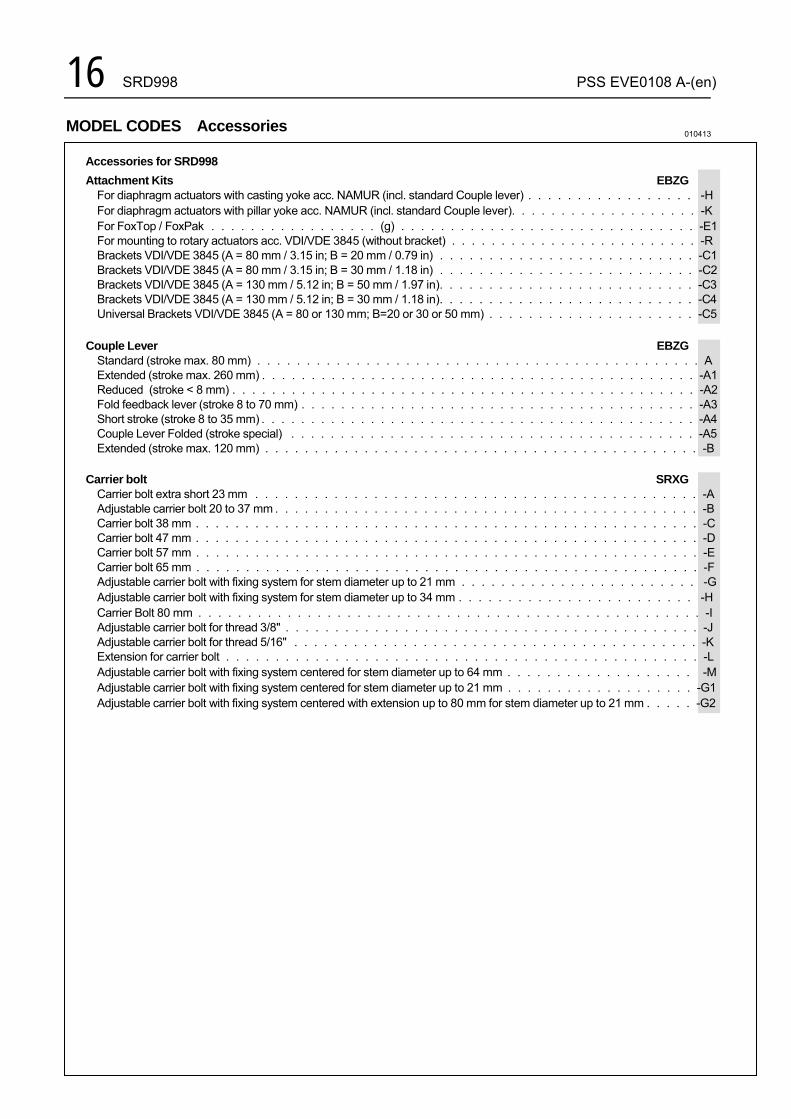
Accessories for SRD998
Attachment Kits EBZG For diaphragm actuators with casting yoke acc. NAMUR (incl. standard Couple lever) . . . . . . . . . . . . . . . . . -H For diaphragm actuators with pillar yoke acc. NAMUR (incl. standard Couple lever). . . . . . . . . . . . . . . . . . . -K For FoxTop / FoxPak . . . . . . . . . . . . . . . . . (g) . . . . . . . . . . . . . . . . . . . . . . . . . . . . . . -E1 For mounting to rotary actuators acc. VDI/VDE 3845 (without bracket) . . . . . . . . . . . . . . . . . . . . . . . . . -R Brackets VDI/VDE 3845 (A = 80 mm / 3.15 in; B = 20 mm / 0.79 in) . . . . . . . . . . . . . . . . . . . . . . . . . . -C1 Brackets VDI/VDE 3845 (A = 80 mm / 3.15 in; B = 30 mm / 1.18 in) . . . . . . . . . . . . . . . . . . . . . . . . . . -C2 Brackets VDI/VDE 3845 (A = 130 mm / 5.12 in; B = 50 mm / 1.97 in). . . . . . . . . . . . . . . . . . . . . . . . . . -C3 Brackets VDI/VDE 3845 (A = 130 mm / 5.12 in; B = 30 mm / 1.18 in). . . . . . . . . . . . . . . . . . . . . . . . . . -C4 Universal Brackets VDI/VDE 3845 (A = 80 or 130 mm; B=20 or 30 or 50 mm) . . . . . . . . . . . . . . . . . . . . . -C5
Couple Lever EBZG Standard (stroke max. 80 mm) . . . . . . . . . . . . . . . . . . . . . . . . . . . . . . . . . . . . . . . . . . . . . A Extended (stroke max. 260 mm) . . . . . . . . . . . . . . . . . . . . . . . . . . . . . . . . . . . . . . . . . . . . -A1 Reduced (stroke < 8 mm) . . . . . . . . . . . . . . . . . . . . . . . . . . . . . . . . . . . . . . . . . . . . . . . -A2 Fold feedback lever (stroke 8 to 70 mm) . . . . . . . . . . . . . . . . . . . . . . . . . . . . . . . . . . . . . . . . -A3 Short stroke (stroke 8 to 35 mm) . . . . . . . . . . . . . . . . . . . . . . . . . . . . . . . . . . . . . . . . . . . . -A4 Couple Lever Folded (stroke special) . . . . . . . . . . . . . . . . . . . . . . . . . . . . . . . . . . . . . . . . . -A5 Extended (stroke max. 120 mm) . . . . . . . . . . . . . . . . . . . . . . . . . . . . . . . . . . . . . . . . . . . . -B
Carrier bolt SRXG Carrier bolt extra short 23 mm . . . . . . . . . . . . . . . . . . . . . . . . . . . . . . . . . . . . . . . . . . . . . -A Adjustable carrier bolt 20 to 37 mm . . . . . . . . . . . . . . . . . . . . . . . . . . . . . . . . . . . . . . . . . . . -B Carrier bolt 38 mm . . . . . . . . . . . . . . . . . . . . . . . . . . . . . . . . . . . . . . . . . . . . . . . . . . . -C Carrier bolt 47 mm . . . . . . . . . . . . . . . . . . . . . . . . . . . . . . . . . . . . . . . . . . . . . . . . . . . -D Carrier bolt 57 mm . . . . . . . . . . . . . . . . . . . . . . . . . . . . . . . . . . . . . . . . . . . . . . . . . . . -E Carrier bolt 65 mm . . . . . . . . . . . . . . . . . . . . . . . . . . . . . . . . . . . . . . . . . . . . . . . . . . . -F Adjustable carrier bolt with fixing system for stem diameter up to 21 mm . . . . . . . . . . . . . . . . . . . . . . . . -G Adjustable carrier bolt with fixing system for stem diameter up to 34 mm . . . . . . . . . . . . . . . . . . . . . . . . -H Carrier Bolt 80 mm . . . . . . . . . . . . . . . . . . . . . . . . . . . . . . . . . . . . . . . . . . . . . . . . . . . -I Adjustable carrier bolt for thread 3/8" . . . . . . . . . . . . . . . . . . . . . . . . . . . . . . . . . . . . . . . . . . -J Adjustable carrier bolt for thread 5/16" . . . . . . . . . . . . . . . . . . . . . . . . . . . . . . . . . . . . . . . . . -K Extension for carrier bolt . . . . . . . . . . . . . . . . . . . . . . . . . . . . . . . . . . . . . . . . . . . . . . . . -L Adjustable carrier bolt with fixing system centered for stem diameter up to 64 mm . . . . . . . . . . . . . . . . . . . -M Adjustable carrier bolt with fixing system centered for stem diameter up to 21 mm . . . . . . . . . . . . . . . . . . . -G1 Adjustable carrier bolt with fixing system centered with extension up to 80 mm for stem diameter up to 21 mm . . . . . -G2
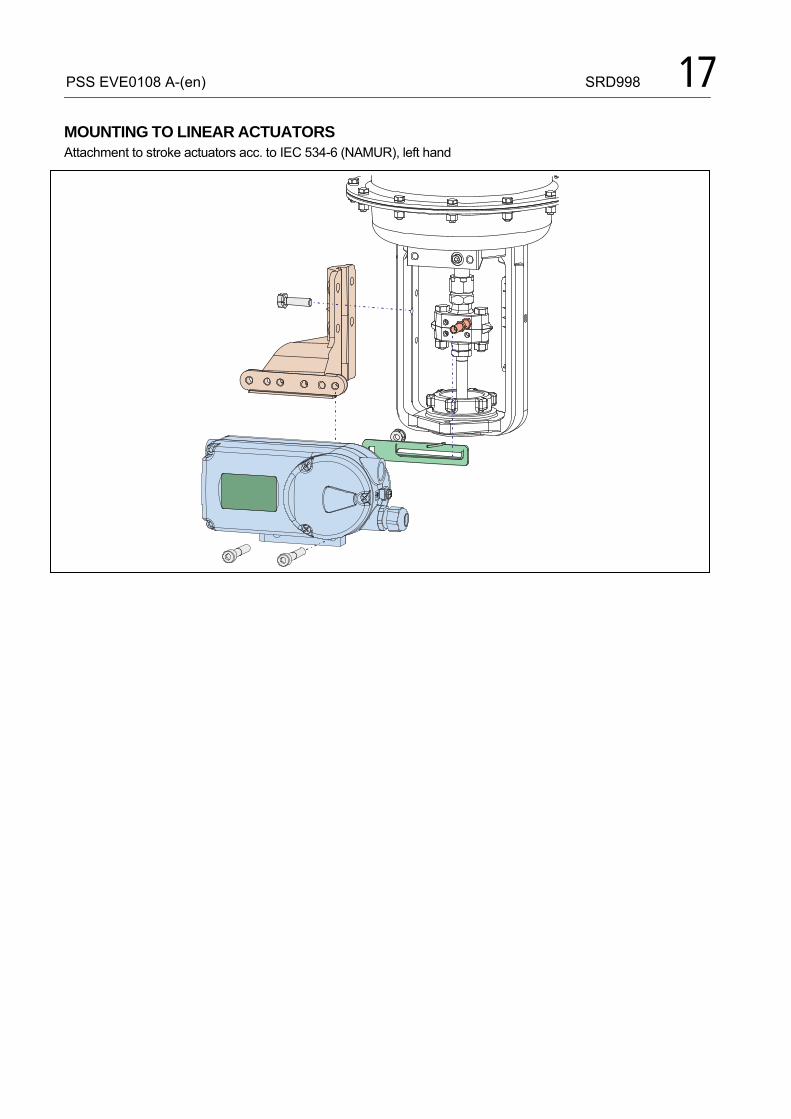
PSS EVE0108 A-(en) SRD998 17
MOUNTING TO LINEAR ACTUATORS Attachment to stroke actuators acc. to IEC 534-6 (NAMUR), left hand
18 SRD998 PSS EVE0108 A-(en)
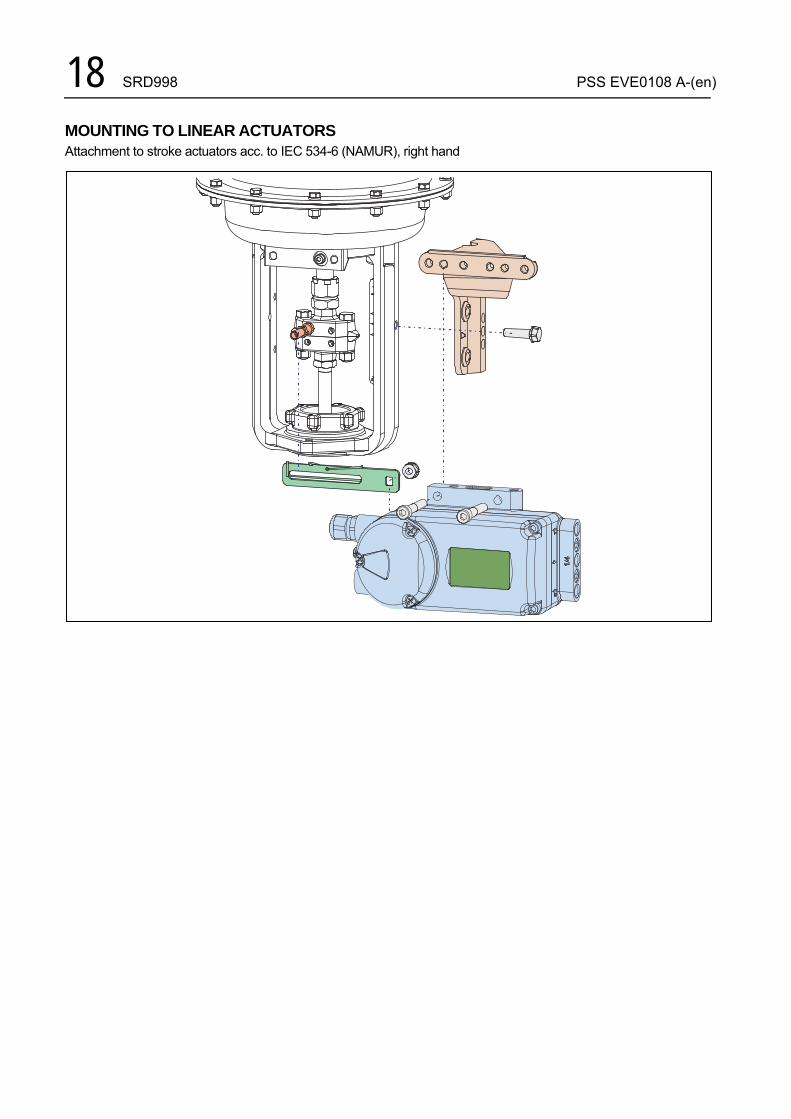
MOUNTING TO LINEAR ACTUATORS Attachment to stroke actuators acc. to IEC 534-6 (NAMUR), right hand

PSS EVE0108 A-(en) SRD998 19
MOUNTING TO ROTARY ACTUATORS Delivery of bracket by manufacturer of actuator
20 SRD998 PSS EVE0108 A-(en)
� �
���
� � �
��
��
���
� � � �
�
���
�
�
���
���
�
�������
� � �
�
� � � � � � � �
�
���
� �
� � � �� � �
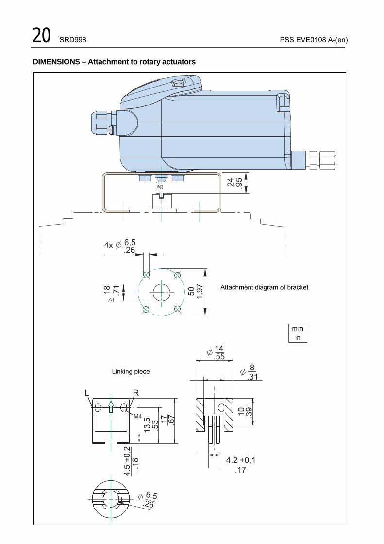
DIMENSIONS – Attachment to rotary actuators
Attachment diagram of bracket
Linking piece
mmin
PSS EVE0108 A-(en) SRD998 21
� �
� �
����
���
���
���
�
� � �
���
� �
� � � �� �
� � �� �
�
� � � �
� �� �
� �� � � � � �
�� � �
�
�
���
� � � �
� � �� � �
�� � �
��
��
�� � �
� � � � � � �� � � � � � � �
�� � � �
���
� �� � �
� � � � �
� �� � �
���
���
� �� � �
� � � �
� � � � �
� �� � �
���
� �� � �
� �� � �
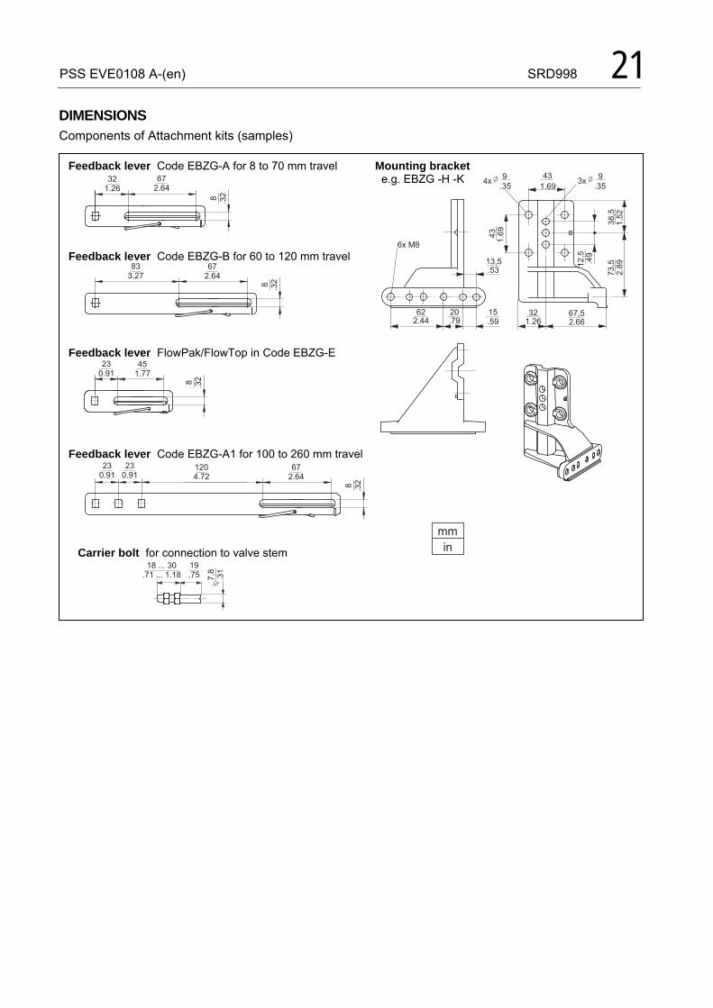
DIMENSIONS Components of Attachment kits (samples) Feedback lever Code EBZG-A for 8 to 70 mm travel Mounting bracket e.g. EBZG -H -K
Feedback lever Code EBZG-B for 60 to 120 mm travel
Feedback lever FlowPak/FlowTop in Code EBZG-E
Feedback lever Code EBZG-A1 for 100 to 260 mm travel
Carrier bolt for connection to valve stem
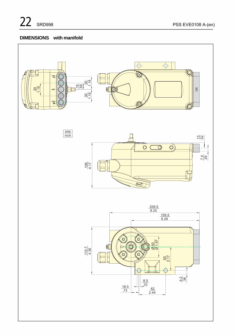
22 SRD998 PSS EVE0108 A-(en) DIMENSIONS with manifold
� � � � � �� � �
� � � � � � � � � �
� � � �� � � !
�����
��� �"������
����"����
����
���
�����
���
� � � �� � �
� � � �� �
� � � �� � �
���
���
����
��
���
���
��� �
���
����
�
����
�
����
�
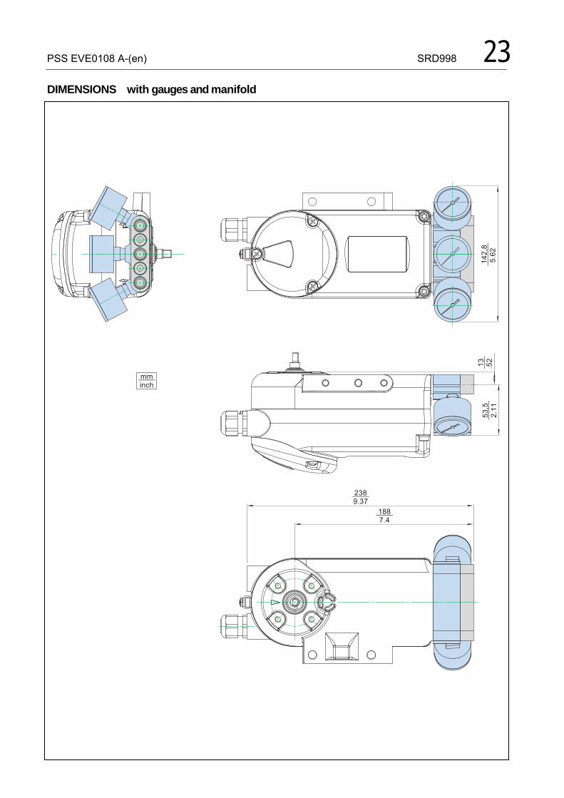
PSS EVE0108 A-(en) SRD998 23 DIMENSIONS with gauges and manifold
� � � �� � � !
���
���
� ���
����
������
���
� �� � �
� � � �� � � � �

24 SRD998 PSS EVE0108 A-(en)
Invensys Systems, Inc. 38 Neponset Avenue Foxboro, MA 02035 United States of America
Global Customer Support Toll free: 1-866-746-6477 Global: 1-508-549-2424 Website: http://support.ips.invensys.com
Copyright 2010-2016 Invensys Systems, Inc. All rights reserved. Invensys, Foxboro, and I/A Series are trade-marks of Invensys Limited, its subsidiaries, and affiliates. All other trademarks are the property of their respective owners. DOKT 558 742 027 i00 FD-PSS-PO-998-EN 0816