srd991 intelligent positioner with hart, foxcom ...kk...srd991 intelligent positioner with hart,...
TRANSCRIPT

SRD991 Intelligent Positioner with HART, FoxCom,PROFIBUS or FOUNDATION Fieldbus
The intelligent positioner SRD991 is designed to operate pneumatic valve actuators and can be operated fromcontrol systems (e.g. the Foxboro I/A Series System), controllers or PC-based configuration- and operation toolssuch as PC20 / IFDC. The positioner is available with different communication protocols. This includes versions withanalog setpoint (4 to 20 mA) and superimposed HART- or FoxCom signal; digital with FoxCom protocol, or fieldbuscommunication according to PROFIBUS-PA and FOUNDATION fieldbus H1 based on IEC 1158-2.
FEATURES
• Auto-start with self-calibration
• Self diagnostics, status- and diagnostic messages
• Communication HART, FoxCom, PROFIBUS-PAor FOUNDATION Fieldbus H1
• Configuration by means of local keys,hand-held terminal, PC or I/A Series system
• Easy operation with three key pads
• Low air consumption
• Low vibration effect in all directions
• Stroke 8 to 120 mm (0.3 to 4.7 in)
• Angle range up to 95 °
• Supply air pressure up to 6 bar (90 psig)
• Single or double-acting
• Mechanical travel indicator
• Mounting on linear actuators directly oraccording to IEC 534, Part 6 (NAMUR)
• Mounting on rotary actuators according toVDI/VDE 3845
• Protection class IP 65, NEMA 4X
• Explosion protection:EEx ia IIC according to CENELEC / ATEX or“Intrinsic safety” according to FM and CSA
• Built-in independent inductive limit switches(optional)
• Sensors for supply air pressure and outputpressure (optional)
• Booster relay to minimize stroke time(optional)
• Additional Inputs / outputs (optional):– 2 binary outputs (limit signals)– Position feedback 4 to 20 mA,
1 Alarm output– 2 binary inputs
Product Specifications 01.2001 PSS EVE0105 A-(en)

FUNCTIONAL SPECIFICATIONS (common data for all versions)
Travel rangeStroke range . . . . . . . . . . 8 to 70 mm (0.3 to 2.8 in),
and 60 to 120 mm(2.4 to 4.7 in)
Rotation angle range . . . . up to 95 °(without mechanical stop)
CharacteristicActing . . . . . . . . . . . . . . . configurable: direct / inverseSplit range. . . . . . . . . . . . practicableCharacteristic curve. . . . . configurable:
linear /equal percentage /inverse equal percentage /quick opening /freely defined with max.22 points
Stroke limitation. . . . . . . . configurableTight close range. . . . . . . with hysteresis
configurable
Travel indication . . . mechanical (displaywindow)
transmission (approx.) . . . 1:2 or 1:6 switchable
OutputAction . . . . . . . . . . . . . . . single acting
optional double actingOutput to actuator . . . . . . 0 to ~100 % of supply air
pressure
SupplySupply air pressure . . . . . 1.4 to 6 bar (20 to 90 psig)Supply air . . . . . . . . . . . . free of oil, dust, water
according to IEC 654-2
Additional features
Autostart . . . . . . . . . . . . travel direction, zero, span,control parameters(control parametersadjustable via local keypads and communication)
Position feedback . . . . . via communicationoptional . . . . . . . . . . . . . 4 to 20 mA by means of
additional in-/outputs
Alarms . . . . . . . . . . . . . . via communicationoptional . . . . . . . . . . . . . 1 Alarm output by means
of additional in-/outputs
Limit values . . . . . . . . . . via communicationdetects position alarms
1) Data measured according to VDI/VDE 21772) With stroke 30 mm and lever length 90 mm
Online diagnosis . . . . . . via communication- determines number of cycles, movements of actuator- shows condition of device:
- state of position sensor- exceeding range- actuator is jammed (remaining control deviation)resp. interruption in feedback control system ofpositioner
- if equipped with pressure sensors (optional):- surveillance of air supply and positioning pressure- each with display of physical value
Additional diagnostical possibilities in controloperation by means of external sensors (optional).
Response characteristic 1) 2)
Sensitivity . . . . . . . . . . . . ≤ 0.1 % of travel spanNon-linearity (terminalbased adjustment). . . . . . ≤ 0.4 % of travel spanHysteresis . . . . . . . . . . . . ≤ 0.3 % of travel spanSupply air dependence . . ≤ 0.1 % / 1 bar (15 psi)Temperature effect . . . . . ≤ 0.3 % / 10 KMechanical vibration10 to 60 Hz up to 0.14 mm,60 to 500 Hz up to 2 g ≤ 0.25 % of travel span
Air output ln/h (scfh)at max. deviation, single and double acting
Supply airpressurebar (psig)
1.4(20)
2(30)
4(60)
6(90)
withoutbooster
2 700(95)
3 500(124)
5 500(194)
7 500(265)
withboostercode F, G
18 000(636)
24 000(847)
40 000(1 492)
55 000(1 942)
withboostercode H
36 000(1 271)
48 000(1 695)
80 000(2 825)
110 000(3 884)
The air capacity can be reduced with built-in nozzles.
Air consumption (steady state) ln/h (scfh)
Supply airpressurebar (psig)
1.4(20)
3(45)
6(90)
singleacting
100(3.5)
110(3.9)
150(5.3)
doubleacting
200(7.0)
220(7.8)
300(10.6)
2 SRD991 PSS EVE0105 A-(en)

Failure handlingSafety position at- Air supply failure . . . . . . pressure y1 = zero- Electric power failure . . . pressure y1 = zero- Failure of electronics . . . configurable as
pressure y1 = zero orstop at last value
- Failure of communicationis recognized by configurable watch dog withresponse delay of 0.1 s to 24 h
behavior . . . . . . . . . . configurable aspressure y1 = zero orstop at last value ora configured value
Diagnostic report . . . . . . . via communication- historical status . . . . . . . is set if alarm was acti-
vated at any time (also just short alarms)Reset . . . . . . . . . . . . . . . by acknowledging
PHYSICAL SPECIFICATIONS
Mounting
Attachmentto stroke actuators- direct . . . . . . . . . . . . . . . with attachment kit EBZG -D- direct, FoxPak/FoxTop. . with attachment kit EBZG -E- for casting yoke acc. toIEC 534-6 (NAMUR) . . . with attachment kit EBZG -HStroke range
with standard feedback lever. 8 - 70 mmwith extended feedback lever 60 - 120 mm
- for pillar yoke acc. toIEC 534-6 (NAMUR) . . . with attachment kit EBZG -KStroke range
with standard feedback lever. 8 - 70 mmwith extended feedback lever 60 - 120 mm
- to rotary actuatorsacc. to VDI/VDE 3845. . with attachment kit EBZG -R
- Further attachment kits on request -
Mounting orientation . . . . see attachment dimen-sions on pages 16 to 18
WeightSingle acting . . . . . . . . . . approx. 1.7 kg (3.7 lbs)Double acting . . . . . . . . . approx. 2.0 kg (4.4 lbs)
MaterialsHousing. . . . . . . . . . . . . . Aluminum (Alloy No. 230)
finished with DD-varnishAll moving parts offeedback system . . . . . . . 1.4306 / 1.4571 / 1.4104Mounting bracket. . . . . . . Aluminum (Alloy No. 230)
Pneumatic connectionNAMUR mounting . . . . . . 3 x female threads1/4-18 NPT for pipe diameter 6 to 12 mm (0.24 to 0.47in) for air supply and outputs y1, y2 to the actuatorDirect mounting . . . . . . . . Instead of the output y1
an air connection on the backside with O-ringwill be used (closed at NAMUR mounting).
Ambient conditionsOperating conditions . . . . acc. to IEC 654-1The device can be operated at a class Dx locationAmbient temperature . . . . –40 to 80 °C (–40 to 176 °F)
(devices before rev 2.1 . –20 to 80 °C (–4 to176 °F)Relative humidity . . . . . . . ≤ 100 %Transport and storage
Ambient temperature . . . –40 to 80 °C (–40 to176 °F)Storage conditions according to IEC 60721-3-1:1K5; 1B1; 1C2; 1S3; 1M2
Protection classacc. to IEC 529 . . . . . . . . IP 65 1)
acc. to NEMA . . . . . . . . . Type 4X
Electromagnetic compatibility EMCOperating conditions . . . . industrial environmentImmunity according to- EN 50 082-2 . . . . . . . . . fulfilledEmission according to- EN 55 011Group 1, Class A . . . . . . fulfilled
- EN 50 081-2 . . . . . . . . . fulfilledNAMUR recommendation Status May 1993 fulfilled
SAFETY REQUIREMENTS
CE label
Electromagneticcompatibility 2) . . . . . . . . . 89/336/EWGLow-voltage regulation. . . 73/23/EWG not applicable
Safety
According to EN 61010-1(or IEC 1010-1) . . . . . . . . safety class III
Overvoltage Category IInternal fuses. . . . . . . . . . not replaceableExternal fuses . . . . . . . . . limitation of power supplies
for fire protection must be observed acc. toEN 61010-1, appendix F (or IEC 1010-1).
1) Under service as directed2) With PROFIBUS or FOUNDATION Fieldbus only, if shield of wiring is
grounded on both sides.
PSS EVE0105 A-(en) SRD991 3

FUNCTIONAL SPECIFICATIONS (basic device, HART or FoxCom version)
With HART communication:Input . . . . . . . . . . . . . . . . Two-wire system, 4-20 mAReverse polarity protection standard featureOperating range . . . . . . . 3.6 to 21 mAVoltage . . . . . . . . . . . . . . DC 12 to 36 Vmax. load . . . . . . . . . . . . 600 ΩCommunication signal . . . HART, 1200 Baud, FSK 1)
modulated on 4 to 20 mAInput impedance Zi . . . . . ~ 250 Ω (0.5 to 5 kHz)Configuration:local . . . . . . . . . . . . . . . . with local keys and LEDs 2)
Software . . . . . . . . . . . . . PC20/IFDC or ABO991,WPP991
Hardware . . . . . . . . . . . . Modem MOD991 for PC,IBM compatible
Hand Terminal. . . . . . . . . HT991See also product specifications “Accessories fordevices with HART Protocol” PSS EMO0100 A-(en)
I/A Series System . . . . . . on requestother Control systems . . . AMS
Electrical ConnectionLine entry . . . . . . . . . . . . 1 or 2 cable glands
M20 x1.5 (others withAdapter AD-...)
Cable diameter . . . . . . . . 6 to 12 mm (0.24 to 0.47 in)Screw terminals. . . . . . . . 2 terminals for input,optional . . . . . . . . . . . . 4 additional terminals for
- two binary outputs or- position feedback 4 - 20 mA or- binary inputs
Wire cross section . . . . . . 0.3 to 2.5 mm2 (AWG 22-14)
Test sockets- for connection of communicators- for non-interruptable current measurement atCode H, F, E; interlock diode can be switched off
With FOXCOM communication:Operating mode digitalInput . . . . . . . . . . . . . . . . Two-wire system, digitalReverse polarity protection standard featureSupply voltage. . . . . . . . . DC 13 to 48 VSupply current . . . . . . . . . ~ 9 mA at 24 VCommunication signal . . . FoxCom dig., 4800 Baud,
FSK1) modulated onsupply voltage
Input impedance Zi . . . . . ~ 500 Ω (0.5 to 20 kHz)Configuration:local . . . . . . . . . . . . . . . . with local keys and LEDs 2)
Software . . . . . . . . . . . . . PC20 / IFDCHardware . . . . . . . . . . . . Modem PC10I/A Series System . . . . . . with FBM43
Operating mode analogInput . . . . . . . . . . . . . . . . Two-wire system, 4-20 mAReverse polarity protection standard featureOperating range . . . . . . . 3.6 to 21.5 mAVoltage . . . . . . . . . . . . . . DC 13 to 48 Vmax. Load . . . . . . . . . . . . 650 ΩCommunication signal . . . FoxCom, 600 baud, FSK 1)
modulated on 4 to 20 mAInput impedance Zi . . . . . ~ 500 Ω (0.5 to 20 kHz)Configuration:local . . . . . . . . . . . . . . . . with local keys and LEDs 2)
Software . . . . . . . . . . . . . PC20 / IFDCHardware . . . . . . . . . . . . Modem PC10I/A Series System . . . . . . with FBM44
1) Frequency Shift Key2) Key configuration lockable with software
4 SRD991 PSS EVE0105 A-(en)

Electrical classification hereto: 1) 2) (basic device,HART or FoxCom version
See certificate of conformity EX EVE0105 A
Type of protection CENELEC “intrinsically safe”Type BIA 637 . . . . . . . . . EEx ia IIC T4Certificate of conformity . . PTB No. Ex-96.D.2175For use in hazardous areas in circuits certified asintrinsically safe with the following maximum values:Input circuit:Umax = 30 V, Imax = 130 mA, Pmax = 0,9 WLi = negligible, Ci = 1,4 nF
Ambient temperature . . . . max. 80 °C (176 °F)
Explosion protection Zone 2It is recommended to use the positioner with explo-sion protection “intrinsically safe” (consider tempera-ture class).In the Federal Republic of Germany these positionersmay be operated in Zone 2 with non-intrinsically safecircuits if the operating values do not exceed themaximum reference values.
Type of protection FM “intrinsic safety”Class I, Div. 1, Groups A, B, C, D, hazardous loca-tions indoor and outdoor, NEMA Type 4X
Type of protection FM “non-incendive”Class I, Div. 2, Groups A, B, C, D, F, G, hazardouslocations indoor and outdoor, NEMA Type 4X
Type of protection CSA “intrinsic safety”Class I, Div. 1, Groups A, B, C, D, hazardous loca-tions indoor and outdoor, NEMA Type 4X *)
*) In preparation1) With appropriate order only2) National requirements must be observed
PSS EVE0105 A-(en) SRD991 5

ADDITIONAL EQUIPMENT (built into basic device, HART or FoxCom version)
Additional Inputs / Outputs:Two binary outputsStroke / angle derivated from positioner feedback,configurablegalvanically separated 2 limit signals, two-wiresystem, according to DIN 19234supply voltage . . . . . . . . external, DC 8 to 48 V 1)
Logic:limit value not exceeded < 1mAlimit value exceeded. . . ≥ 2.2 mAdevice fault . . . . . . . . . < 50 µA
Reference: AB1 for upper, AB2 for lower limitTerminals for AB1 . . . . . . 81+, 82–
AB2 . . . . . . 83+, 84–
Explosion protection hereto:Type of protection CENELEC “intrinsically safe”Type BIA 637 L . . . . . . . . EEx ia IICCertificate of Conformity . PTB Nr.Ex-96.D.2175For use in hazardous areas in circuits certified asintrinsically safe with the following maximum values:
Ui 30 V 15 V 30 V
Ii 18 mA 130 mA 130 mA
Pi 0.9 W 0.9 W 272 mWThe applicable internal inductance and capacitance is negligible.
Type of protection FM “intrinsic safety”Class I, Div. 1, Groups A, B, C, D, hazardous loca-tions indoor and outdoor, NEMA Type 4X
Type of protection FM “non-incendive”Class I, Div. 2, Groups A, B, C, D, F, G, hazardouslocations indoor and outdoor, NEMA Type 4X
Type of protection CSA “intrinsic safety”Class I, Div. 1, Groups A, B, C, D, hazardous loca-tions indoor and outdoor, NEMA Type 4X *)
One option board “Additional Inputs / Outputs” 8plugged in main board 40
*) In preparation1) In hazardous areas other values, see “Explosion protection”
Additional Inputs / Outputs:Position feedback 4 to 20 mAStroke / angle derivated from positioner feedback,One output analog, galvanically separated
two-wire systemsupply voltage . . . . . . . DC 8 to 48 V 1)
signal range . . . . . . . . . 3.8 to 21.5 mA0 % and 100 % configurabledevice fault . . . . . . . . . . < 1 mA
Terminals for AI1 . . . . . . . 31+, 32–
One Binary output alarm, galvanically separated,two-wire system, according to DIN 19234supply voltage . . . . . . . . external, DC 8 to 48 V 1)
logic . . . . . . . . . . . . . . . no alarm < 1 mAalarm ≥ 2.2 mAdevice fault < 50 µA
Terminals for AB1 . . . . . . 81+, 82–The binary output for Alarm will be activated in thefollowing cases:- Remaining control deviation- Circuit to I/P module is disturbed- Circuit to potentiometer is disturbed- Calibration error:
- no angle calibration- no current calibration
- Autostart failedThese alarms can be selected by means of communication.
Explosion protection hereto:Type of protection CENELEC “intrinsically safe”Type BIA 637 M. . . . . . . . EEx ia IICCertificate of Conformity. . PTB Nr.Ex-96.D.2175
Channel 1: Alarm outputFor use in hazardous areas in circuits certified asintrinsically safe with the following maximum values:
Ui 30 V 15 V 30 V
Ii 18 mA 130 mA 130 mA
Pi 0.9 W 0.9 W 272 mWThe applicable internal inductance and capacitance is negligible.
Channel 2: Position feedbackFor use in hazardous areas in circuits certified asintrinsically safe with the following maximum values:
Ui = 30 V, Ii = 130 mA, Pi = 0.9 WThe applicable internal inductance and capacitance is negligible.
Type of protection FM “intrinsic safety”Class I, Div. 1, Groups A, B, C, D, hazardous loca-tions indoor and outdoor, NEMA Type 4X
Type of protection FM “non-incendive”Class I, Div. 2, Groups A, B, C, D, F, G, hazardouslocations indoor and outdoor, NEMA Type 4X
Type of protection CSA “intrinsic safety”Class I, Div. 1, Groups A, B, C, D, hazardous loca-tions indoor and outdoor, NEMA Type 4X *)
6 SRD991 PSS EVE0105 A-(en)
8
40

Additional Inputs / Outputs:Two Binary inputsTwo independent binary inputs with internal supply forconnection of sensors. A connected switch is loadedwith 3.5 V, 150 µA.Both binary inputs can be used for diagnostics or alsoconfigurable for the control functions.
Switch 1 Switch 2 Actuator control functionclose close normal operationopen close go to stop at 0 %close open go to stop at 100 %open open hold last position
Terminals for EB1 . . . . . . 13+, 14–EB2 . . . . . . 15+, 16–
Explosion protection hereto:Type of protection CENELEC “intrinsically safe”Type BIA 637 N. . . . . . . . EEx ia IICCertificate of Conformity. . PTB Nr.Ex-96.D.2175For use in hazardous areas in circuits certified asintrinsically safe with the following maximum values:Uo=7.25V, Io=46.4mA,Po=84mW,Lo=2mH,Co=1.4µF
Type of protection FM “intrinsic safety”Class I, Div. 1, Groups A, B, C, D, hazardous loca-tions indoor and outdoor, NEMA Type 4X
Type of protection FM “non-incendive”Class I, Div. 2, Groups A, B, C, D, F, G, hazardouslocations indoor and outdoor, NEMA Type 4X
Type of protection CSA “intrinsic safety”Class I, Div. 1, Groups A, B, C, D, hazardous loca-tions indoor and outdoor, NEMA Type 4X *)
*) In preparation2) Operating mode min. (= low) / max. (= high) selectable by adjustment
of switch vanes3) Data measured according to VDI/VDE 21774) With stroke 30 mm and lever length 90 mm
Limit Switch, built into basic device,
HART or FoxCom versionInductive Limit Switch– normal version (SJ2-N) . . . . . Option T– security version (SJ2-SN) . . . . Option UStroke / angle derivated from positioner feedback,two-wire systemOutput. . . . . . . . . . . . . . . 2 inductive proximity sen-
sors acc. to DIN 19 234 or NAMUR for connectionto switching amplifier with intrinsically safe controlcircuit 2)
Current consumptionvane clear . . . . . . . . . . . ≥ 2.2 mAvane interposed. . . . . . . ≤ 1 mA
for control circuit with the following electrical valuessupply voltage . . . . . . . . DC 8 V, Riapprox. 1 kΩresidual ripple . . . . . . . . ≤ 10 % p.p.permissibleline resistance . . . . . . . . ≤ 100 Ω
Response characteristic 3) 4)
switching differential . . . ≤ 1 %switching point repeatability . . . ≤ 0.2 %
Terminals for GW1 . . . . . 41+, 42–GW2 . . . . . 53+, 54–
Explosion protection hereto:Type of protection CENELEC “intrinsically safe”Type BIA 637 K . . . . . . . . EEx ia IICCertificate of Conformity. . PTB Nr.Ex-96.D.2175For use in hazardous areas in circuits certified asintrinsically safe with the following maximum values:
Umax = 16 V, Imax = 76 mA, Pmax = 242 mWLi = 100 µH, Ci = 60 nF
Permissible temperature class and ambient tempera-ture dependent on the built-in intelligent positioner.
Type of protection FM “intrinsic safety”Class I, Div. 1, Groups A, B, C, D, hazardous loca-tions indoor and outdoor, NEMA Type 4X
Type of protection FM “non-incendive”Class I, Div. 2, Groups A, B, C, D, F, G, hazardouslocations indoor and outdoor, NEMA Type 4X
Type of protection CSA “intrinsic safety”Class I, Div. 1, Groups A, B, C, D, hazardous loca-tions indoor and outdoor, NEMA Type 4X *)
PSS EVE0105 A-(en) SRD991 7

FUNCTIONAL SPECIFICATION(basic device, PROFIBUS-PA or FOUNDATION Fieldbus H1 version)
With Fieldbus communication:PROFIBUS-PAInput signal . . . . . . . . . . . digitalSupply voltage. . . . . . . . . DC 9 to 32 V 1)
Operating current. . . . . . . 10.5 mA ± 0.5 mA(base current)
Current amplitude . . . . . . ± 8 mAFault current . . . . . . . . . . base current + 0 mA in
case of fault in device, orbase current + 4 mA bymeans of independentFDE-safety circuit
Operating values . . . . . . . according to IEC 1158-2Bus connection . . . . . . . . Fieldbus interface based
on IEC 1158-2according to FISCO-Model
Power supply. . . . . . . . . . Power supply is achieveddependant on the applica-tion by means of segment-coupler
Data transfer . . . . . . . . . . according to PROFIBUS- PAprofile class B based onEN 50170 and DIN 19245part 4
GSD file . . . . . . . . . . . . . the actual file can be down-loaded from our homepage
Configuration:local . . . . . . . . . . . . . . . . with local keys and LEDs 2)
Software . . . . . . . . . . . . . PC20 / IFDCHardware . . . . . . . . . . . . PC- or PCMCIA-interfaces
from Softing 3)
I/A Series System . . . . . . on requestOther control systems . . . PROFIBUS-PA compatible
Electrical connectionConnection . . . . . . . . . . . terminals acc. to IEC 1158-2Screw terminals. . . . . . . . 2 terminals for input,option . . . . . . . . . . . . . . 4 additional terminals for
- two binary outputs or- position feedback 4 to 20 mA or- binary inputs
Line entry . . . . . . . . . . . . 1 or 2 cable glandsM20 x1.5 (others withAdapter AD-...)
Fieldbus-cable-types . . . . twisted and shielded two-wire cable (Type A) accor-ding to recommendationbased on IEC 1158-2
Cable diameter . . . . . . . . 6 to 12 mm (0.24 to 0.47 in)
With Fieldbus communication:FOUNDATION Fieldbus H1Input signal . . . . . . . . . . . digitalSupply voltage. . . . . . . . . DC 9 to 32 V 1)
Operating current. . . . . . . 10.5 mA ± 0.5 mA(base current)
Current amplitude . . . . . . ± 8 mAFault current . . . . . . . . . . base current + 0 mA in
case of fault in device, orbase current + 4 mA bymeans of independentFDE-safety circuit
Operating values . . . . . . . according to IEC 1158-2Bus connection . . . . . . . . Fieldbus interface based
on IEC 1158-2according to FISCO-Model
Power supply. . . . . . . . . . Power supply is achieveddependant on the applica-tion by means of segment-coupler
Data transfer . . . . . . . . . . FF Specification Rev. 1.4,Link-Master (LAS)
Function blocks . . . . . . . . AO, Transducer, Resource,PID (in preparation)
Files . . . . . . . . . . . . . . . . the actual file can be down-loaded from our homepage
Configuration:local . . . . . . . . . . . . . . . . with local keys and LEDs 2)
Software . . . . . . . . . . . . . National InstrumentsNI-FBUS configurator
Hardware . . . . . . . . . . . . FBUS-interfaces fromNational Instruments(AT-FBUS and PCMCIA-FBUS)
I/A Series System . . . . . . on requestOther control systems . . . FOUNDATION Fieldbus
H1-compatible
1) Data of “intrinsically safe” version2) Key configuration lockable with software3) PC20/IFDC is exclusively supported by these interfaces
8 SRD991 PSS EVE0105 A-(de)

Electrical classification: 1) 2) (basic device, versionPROFIBUS-PA or FOUNDATION Fieldbus H1)
Type of protection “intrinsically safety”II 2 G EEx ia IIB/IIC, II 2 G EEx ib IIB/IICTemperature classes T4 / T6(Electronics family AI 638 )EC Approval document No. PTB 00 ATEX 2128For connections in hazardous areas with “intrinsicallysafe” certified (fieldbus) circuits, with the maximumvalues:Ui = 24 V; Ii = 380 mA; Pi = 5.2 WInternal capacitance and inductance:Ci = 1.3 nF differential or 5.3 nF to earthLi = 5 µH
Ambient temperature ranges:Temperature class T4: –40 to 80°CTemperature class T6: –40 to 55°C
The input circuit is galvanically separated from earth.
The input is suitable for connection to a fieldbus systemaccording to the FISCO model (e.g. PROFIBUS PA)
Type of protection “intrinsically safety”II 3 G EEx n A/L IIB/IIC *)
Type of protection FM “intrinsic safety”Class I, Div. 1, Groups A, B, C, D, hazardous loca-tions indoor and outdoor, NEMA Type 4X *)
Type of protection FM “non-incendive”Class I, Div. 2, Groups A, B, C, D, F, G, hazardouslocations indoor and outdoor, NEMA Type 4X *)
Type of protection CSA “intrinsic safety”Class I, Div. 1, Groups A, B, C, D, hazardous loca-tions indoor and outdoor, NEMA Type 4X *)
*) In preparation1) With appropriate order only2) National requirements must be observed
PSS EVE0105 A-(en) SRD991 9

ADDITIONAL EQUIPMENT(built into basic device, PROFIBUS-PA or FOUNDATION Fieldbus H1 version)
Additional Inputs / Outputs:Two binary outputs (limit signals)Stroke / angle derivated from positioner feedback,configurablegalvanically separated 2 limit signals, two-wiresystem, according to DIN 19234, for external supplysupply voltage . . . . . . . . DC 8 to 48 V 1)
Logic:limit value not exceeded < 1mAlimit value exceeded. . . ≥ 2.2 mAdevice fault . . . . . . . . . < 50 µA
Reference: AB1 for upper, AB2 for lower limitTerminals for AB1 . . . . . . 81+, 82–
AB2 83+, 84–Explosion protection hereto: (Electronics AI 638 P)Ex protection and temp. classes as basic device.For connections to certified circuits, with the maxi-mum values:Ui=16 V; Ii=80 mA; Pi=250 mWInternal capacitance and inductance: Ci=26 nF, Li=5 µHThe ciruits Binary outputs are galvanically separatedfrom all other circuits and from earth.
Type of protection FM “intrinsic safety”Class I, Div. 1, Groups A, B, C, D, hazardous loca-tions indoor and outdoor, NEMA Type 4X *)
Type of protection FM “non-incendive”Class I, Div. 2, Groups A, B, C, D, F, G, hazardouslocations indoor and outdoor, NEMA Type 4X *)
Type of protection CSA “intrinsic safety”Class I, Div. 1, Groups A, B, C, D, hazardous loca-tions indoor and outdoor, NEMA Type 4X *)
One option board “Additional Inputs / Outputs” 8plugged in main board 40
*) In preparation1) In hazardous areas other values
Additional Inputs / Outputs:Position feedback 4 to 20 mAStroke / angle derivated from positioner feedback,1 output analog, galvanically separated, two-wiresystem according to DIN 19234, for external supply
supply voltage . . . . . . . DC 8 to 48 V 1)
signal range . . . . . . . . . 3.8 to 21.5 mA0 % and 100 % configurabledevice fault . . . . . . . . . . < 1 mATerminals for AI1 . . . . . 31+, 32–
1 Binary output alarm, galvanically separated, two-wiresystem, according to DIN 19234, for external supply
supply voltage . . . . . . . DC 8 to 48 V 1)
Logic . . . . . . . . . . . . . . no alarm < 1 mAalarm ≥ 2.2 mAdevice fault < 50 µA
Terminals for AB1. . . . . . 81+, 82–The binary output for Alarm will be activated in thefollowing cases:- Remaining control deviation- Circuit to I/P module is disturbed- Circuit to potentiometer is disturbed- Calibration error:
- no angle calibration- no current calibration
- Autostart failedThese alarms can be selected by means of commu-nication.
Explosion protection hereto:
Type of protection FM “intrinsic safety”Class I, Div. 1, Groups A, B, C, D, hazardous loca-tions indoor and outdoor, NEMA Type 4X *)
Type of protection FM “non-incendive”Class I, Div. 2, Groups A, B, C, D, F, G, hazardouslocations indoor and outdoor, NEMA Type 4X *)
Type of protection CSA “intrinsic safety”Class I, Div. 1, Groups A, B, C, D, hazardous loca-tions indoor and outdoor, NEMA Type 4X *)
10 SRD991 PSS EVE0105 A-(en)

Additional Inputs / Outputs:Two Binary inputsTwo independent binary inputs, supplied by the basicdevice, for connection of sensors. A connected switchis loaded with 3.5 V, 150 µA.Both binary inputs can be used for diagnostics or alsoconfigurable for the control functions.
Switch 1 Switch 2 Actuator control functionclose close normal operationopen close go to stop at 0 %close open go to stop at 100 %open open hold last position
Terminals for EB1 . . . . . . 13+, 14–EB2 15+, 16–
Explosion protection hereto: (Electronics AI 638B)Ex protection and temp. classes as basic device.At this circuit only circuits which are passive andgalvanically separated from earth may be connected.The circuit has the following maximum values:Uo= 7.88 V; Io= 11.4 mA; Po= 23 mW
Linear characteristics
For the maximum values of outer inductance andcapacitance Lo and Co see the following table (Li andCi integrated):
IIC IIBLo [mH] Co [µF] Lo [mH] Co [µF]
100 0.72 100 3.910 1.1 10 5.51 1.6 1 8.7
0.1 2.7 0.1 150.01 4.7 0.01 27
The ciruits Binary inputs are galvanically connected toall other circuits and galvanically separated from earth.
Type of protection FM “intrinsic safety”Class I, Div. 1, Groups A, B, C, D, hazardous loca-tions indoor and outdoor, NEMA Type 4X *)
Type of protection FM “non-incendive”Class I, Div. 2, Groups A, B, C, D, F, G, hazardouslocations indoor and outdoor, NEMA Type 4X *)
Type of protection CSA “intrinsic safety”Class I, Div. 1, Groups A, B, C, D, hazardous loca-tions indoor and outdoor, NEMA Type 4X *)
Built-in Limit Switch (illustration see page 7)Inductive Limit Switchstandard version (SJ2-N) . . . . option Tsecurity version (SJ2-SN) . . . option UStroke / angle derivated from positioner feedback,two-wire systemOutput. . . . . . . . . . . . . . . 2 inductive proximity sen-
sors acc. to DIN 19 234 or NAMUR for connectionto switching amplifier with intrinsically safe controlcircuit 1)
Current consumptionvane clear . . . . . . . . . . . ≥ 2.2 mAvane interposed. . . . . . . ≤ 1 mA
for control circuit with the following electrical valuessupply voltage . . . . . . . . DC 8 V, Riapprox. 1 kΩsupply voltage range . . . DC 5...25 V (only with ZZZ)residual ripple . . . . . . . . ≤ 10 % p.p.permissibleline resistance . . . . . . . . ≤ 100 Ω
Response characteristic 2) 3)
switching differential . . . ≤ 1 %switching point repeatability . . . ≤ 0.2 %
Terminals for GW1 . . . . . 41+, 42–GW2 . . . . . 53+, 54–
Explosion protection hereto:Standard version “T” (Electronics AI 638T)Ex protection and temp. classes as basic device.For connections to certified circuits, with the maxi-mum values:Ui=16 V; Ii=25 mA; Pi=64 mWInternal capacitance and inductance:Ci=30 nF, Li=100 µHThe ciruits Limit Switch are galvanically separatedfrom all other circuits and from earth.
Security version “U” *)
Type of protection FM “intrinsic safety”Class I, Div. 1, Groups A, B, C, D, hazardous loca-tions indoor and outdoor, NEMA Type 4X *)
Type of protection FM “non-incendive”Class I, Div. 2, Groups A, B, C, D, F, G, hazardouslocations indoor and outdoor, NEMA Type 4X *)
Type of protection CSA “intrinsic safety”Class I, Div. 1, Groups A, B, C, D, hazardous loca-tions indoor and outdoor, NEMA Type 4X *)
*) In preparation1) Operating mode min. (= low) / max. (= high) selectable by adjustment
of switch vanes2) Data measured according to VDI/VDE 21773) With stroke 30 mm and lever length 90 mm
PSS EVE0105 A-(de) SRD991 11

FUNCTIONAL DESIGNATIONS
12 SRD991 PSS EVE0105 A-(en)
1a Adapter, eg. 1/2”-14 NPT1b Cable gland2 Plug, interchangeable with Pos. 13 Screw terminals (11 + / 12 –) for input (w)3a Screw terminals for additional inputs / outputs3b Screw terminals for bus connection IEC 1158-2 3)
4 Ground connection5 Female thread 1/4-18 NPT for output I (y1)6 Female thread 1/4-18 NPT for air supply (s)7 Female thread 1/4-18 NPT for output II (y2)8 Direct attachment hole for output I (y1)9 Feedback shaft
10 Connection manifold for attachmentto stroke actuators
11 Connection base for attachment to rotary actuators12 Travel indicator13 Key UP14 Key DOWN
15 Key M (Menu)16 Status display (1 red LED, 4 green LEDs)17 Damping screw 1) for output I18 Damping screw 1) for output II19 Fixing shaft for limit switch (see page 4)20 Cover with window to 1221 Air vent, dust and water protected22 Data label23 Tip jacks 2) for current measurement, 2 mm dia.24 Switch 2) for current measurement25 Tip jacks 2) for communication, 2 mm dia.26 Arrow is perpendicular to shaft 9 at angle 0 degree27 Ball valve for protection class NEMA 4X28 High cover with built-in limit switch29 Plug for service connector 3)
1) Not available from Rev.2.1 on2) Not with PROFIBUS-PA and FOUNDATION Fieldbus H1 version3) Only with PROFIBUS-PA and FOUNDATION Fieldbus H1 version

MODEL CODES SRD991
PSS EVE0105 A-(en) SRD991 13
Intelligent Positioner SRD991Version
Single acting . . . . . . . . . . . . . . . . . . . . . . . . . . . . . . . . -BDouble acting . . . . . . . . . . . . . . . . . . . . . . . . . . . . . . . . -C
Input/CommunicationHART communication (4-20mA) . . . . . . . . . . . . . . . . . . . . . . . . . . HFOXCOM communication (4-20mA / IT1) . . . . . . . . . . . . . . . . . . . . . . EFOXCOM communication (digital / IT2) . . . . . . . . . . . . . . . . . . . . . . . FPROFIBUS-PA . . . . . . . . . . . . . . . . . . . . . . . . . . . . . . . . . . . PFOUNDATION Fieldbus H1 . . . . . . . . . . . . . . . . . . . . . . . . . . . . Q
Additional Inputs/Outputswithout (e) . . . . . . . . . . . . . . . . . . . . . . . . . . . . . . . . . . . . . . . . . MPrepared for additional In-/Outputs (a) . . . . . . . . . . . . . . . . . . . . . . . . . . . NBinary inputs (a) . . . . . . . . . . . . . . . . . . . . . . . . . . . . . . . . . . . . . . BTwo Binary outputs (a) . . . . . . . . . . . . . . . . . . . . . . . . . . . . . . . . . . . PPosition feedback 4-20mA (a)(e) . . . . . . . . . . . . . . . . . . . . . . . . . . . . . . Q
Built-in limit switchwithout . . . . . . . . . . . . . . . . . . . . . . . . . . . . . . . . . . . . . . . . . . . . . . SInductive limit switch-intrinsic safe (standard version) (a) . . . . . . . . . . . . . . . . . . . . . . TInductive limit switch-intrinsic safe (security version) (a)(e) . . . . . . . . . . . . . . . . . . . . . U
Cable EntryM20x1.5 w/o cable gland . . . . . . . . . . . . . . . . . . . . . . . . . . . . . . . . . . . . . . . . . 1M20x1.5 with one plastic cable gland, color gray . . . . . . . . . . . . . . . . . . . . . . . . . . . . . 7
Electrical classificationwithout . . . . . . . . . . . . . . . . . . . . . . . . . . . . . . . . . . . . . . . . . . . . . . . . . . . . ZZZEEx ia IIC T4 (e) . . . . . . . . . . . . . . . . . . . . . . . . . . . . . . . . . . . . . . . . . . . . . . . . EA4EEx ia/ib IIB/IIC T4/T6 and EEx nA/L IIB/IIC according to ATEX (d). . . . . . . . . . . . . . . . . . . . . . . EAAFM Non-incendive for Class I, Division 2, Groups A, B, C, D,
hazardous locations indoors and outdoors, NEMA 4X (e) . . . . . . . . . . . . . . . . . . . . . . . . . . NFMFM approved for intrinsic safety Class I, Division 1, Groups A, B, C, D,
hazardous locations indoors and outdoors, NEMA 4X (e) . . . . . . . . . . . . . . . . . . . . . . . . . . FAACSA approved for intrinsic saftey Class I, Division 1, Groups A, B, C, D,
hazardous locations indoors and outdoors, NEMA 4X (e) . . . . . . . . . . . . . . . . . . . . . . . . . . CAAOptions
two Built-in pressure sensors for supply air and output to actuator y1 . . . . . . . . . . . . . . . . . . . . . . . . . . -BCustom Configuration . . . . . . . . . . . . . . . . . . . . . . . . . . . . . . . . . . . . . . . . . . . . . . . . . -TTag.No. Labeling Stamped with weather resistant color . . . . . . . . . . . . . . . . . . . . . . . . . . . . . . . . -GTag.No. Labeling Stainless steel label fixed with wire . . . . . . . . . . . . . . . . . . . . . . . . . . . . . . . . . . -L
Example: SRD991 -B H M S 1 ZZZ -L
Footnotes(a) only with Electrical classification ZZZ, EA4, EAA, NFM & FAA others pending(b) not released(c) pending(d) only with input / communication P and Q(e) Not with Input / communication P and Q
PartsAuxiliaries see EVE9902Fittings see EOO9001

! ! " # $ ! ! $ % & ' $ # ( # ( &
) # $ ! % " # $ ! * $ # $ !
) # & + % " # $ ! * $ # $ !
) # $ ! % " # $ ! * $ # $ ! ' $ # ( & + % & # * # " * " $ #
! ! " # $ ! ! $ % & $ ! % " # $ ! * $ # $ ! ' $ # ( * * * % $ ! & # * #
! ! " # $ ! ! $ % & & + % " # $ ! * $ # $ ! ' $ # ( * * * % $ # * # ! &
! ! " # $ ! ! $ % & $ ! % & + % " # $ ! * $ # $ ! ' $ # ( # ( & * * * % $ # * # ! & * * % $ & ' $ # ( # *
, ! & # ( & * " % &+ ! % " - " ' # . .
/
)
0
/ ) 0 1
/ ) 0 1
/ ) 0 1
/ ) 0 1
/ ) 0 1
/ ) 0 1
/ ) 0 1
Accessories, for all basic devices:
Gauges manifold, Code LEXG -J, -MLateral attachment to positionerwith 2 or 3 gaugesIndicating range. . . . . . . . 0 to 10 bar (0 to 150 psig)
Booster relay, Code LEXG -F, -G, -HLateral attachment to positionerAir output. . . . . . . . . . . . . see table on page 2
Two built-in pressure sensors, Code Option -BFor supply air and output to actuator y1Measuring range . . . . . . . 0 to 8 bar (0 to 120 psig)Accuracy . . . . . . . . . . . . . 0.5 %Temperature influence. . . 0.5 % / 10k (–40 to 80 °C)
14 SRD991 PSS EVE0105 A-(en)

Model Codes Accessories
PSS EVE0105 A-(en) SRD991 15
Parts for Intelligent PositionerAttachment kit EBZG
for diaphragm actuators with casting yoke acc. NAMUR (incl. standard couple lever) . . . . . . . . . . . . . . . . . . -Hfor diaphragm actuators with pillar yoke acc. NAMUR (incl. standard couple lever) . . . . . . . . . . . . . . . . . . . -Kfor directly mounting (incl. standard couple lever) . . . . . . . . . . . . . . . . . . . . . . . . . . . . . . . . . . . . -Dfor mounting to rotary actuators acc. VDI/VDE 3845 (without bracket) . . . . . . . . . . . . . . . . . . . . . . . . . . -Rfor FoxTop / FoxPak . . . . . . . . . . . . . . . . . . . . . . . . . . . . . . . . . . . . . . . . . . . . . . . . . . -E
Further Attachment kits on request. See also http://www.foxboro-eckardt.com /Products /Positioners /Attachment kitsCouple lever
standard (stroke max. 80 mm) . . . . . . . . . . . . . . . . . . . . . . . . . . . . . . . . . . . . . . . . . . . . . -Aextended (stroke max. 120 mm) . . . . . . . . . . . . . . . . . . . . . . . . . . . . . . . . . . . . . . . . . . . . -B
Manifold LEXGwith connection G 1/4 . . . . . . . . . . . . . . . . . . . . . . . . . . . . . . . . . . . . . . . . . . . . . . . . . -K
Gauges manifold (connection 1/4 - 18 NPT)without gauges . . . . . . . . . . . . . . . . . . . . . . . . . . . . . . . . . . . . . . . . . . . . . . . . . . . . . -Nwith gauges for version single acting . . . . . . . . . . . . . . . . . . . . . . . . . . . . . . . . . . . . . . . . . . -Jwith gauges for version double acting . . . . . . . . . . . . . . . . . . . . . . . . . . . . . . . . . . . . . . . . . -M
Booster relaywith connection 1/4 -18 NPT for version single acting . . . . . . . . . . . . . . . . . . . . . . . . . . . . . . . . . . -Fwith connection 1/4 -18 NPT for version double acting . . . . . . . . . . . . . . . . . . . . . . . . . . . . . . . . . -Gwith connection 1/2 -18 NPT for version single acting with doubled output capacity . . . . . . . . . . . . . . . . . . . -H
Adapter (Material SS) ADAdapter PG 13.5 to 1/2" - 14 NPT (internal thread) . . . . . . . . . . . . . . . . . . . . . . . . . . . . . . . . . . -A1Adapter PG 13.5 to M20 x 1,5 (internal thread) . . . . . . . . . . . . . . . . . . . . . . . . . . . . . . . . . . . . -A2Adapter 1/2" NPT to 3/4" NPT . . . . . . . . . . . . . . . . . . . . . . . . . . . . . . . . . . . . . . . . . . . . . -A3Adapter PG 13.5 to G 1/2" (internal thread) . . . . . . . . . . . . . . . . . . . . . . . . . . . . . . . . . . . . . . -A4Adapter (stainless steel) M20x1.5 to 1/2"-14NPT (internal thread) . . . . . . . . . . . . . . . . . . . . . . . . . . . -A6Adapter (stainless steel) M20x1.5 to PG 13.5 (internal thread) . . . . . . . . . . . . . . . . . . . . . . . . . . . . . -A7Adapter (stainless steel) M20x1.5 to G 1/2" (internal thread) . . . . . . . . . . . . . . . . . . . . . . . . . . . . . . -A8Adapter (plastic) M20x1.5 to PG 13.5 (internal thread) . . . . . . . . . . . . . . . . . . . . . . . . . . . . . . . . . -A9
Cable gland BUSGPG 13.5 Plug-connector for Fieldbus (ss/ threaded connection 7/8 - UN) . . . . . . . . . . . . . . . . . . . . . . . . -F1M20x1.5 Plug-connector for Fieldbus (ss/ threaded connection 7/8 - UN) . . . . . . . . . . . . . . . . . . . . . . . . -F2PG 13.5 plastics, color gray . . . . . . . . . . . . . . . . . . . . . . . . . . . . . . . . . . . . . . . . . . . . . . -K1PG 13.5 plastics, color blue . . . . . . . . . . . . . . . . . . . . . . . . . . . . . . . . . . . . . . . . . . . . . . -K2PG 13.5 plastics, color white . . . . . . . . . . . . . . . . . . . . . . . . . . . . . . . . . . . . . . . . . . . . . -K4M20x1.5 plastics, color gray . . . . . . . . . . . . . . . . . . . . . . . . . . . . . . . . . . . . . . . . . . . . . . -K6M20x1.5 plastics, color blue . . . . . . . . . . . . . . . . . . . . . . . . . . . . . . . . . . . . . . . . . . . . . . -K7M20x1.5 plastics, color black. . . . . . . . . . . . . . . . . . . . . . . . . . . . . . . . . . . . . . . . . . . . . . -K8M20x1.5 plastics, color white . . . . . . . . . . . . . . . . . . . . . . . . . . . . . . . . . . . . . . . . . . . . . -K9PG 13.5 Plug-connector for Fieldbus (ss/ threaded connection M12) . . . . . . . . . . . . . . . . . . . . . . . . . . -P1PG 13.5 HF-cable gland for Fieldbus (ss) . . . . . . . . . . . . . . . . . . . . . . . . . . . . . . . . . . . . . . . -P2M20x1.5 Plug-connector for Fieldbus (ss/ threaded connection M12) . . . . . . . . . . . . . . . . . . . . . . . . . -P3M20x1.5 HF-cable gland for Fieldbus (ss) . . . . . . . . . . . . . . . . . . . . . . . . . . . . . . . . . . . . . . . -P4PG 13.5 stainless steel . . . . . . . . . . . . . . . . . . . . . . . . . . . . . . . . . . . . . . . . . . . . . . . . -S1M20x1.5 stainless steel . . . . . . . . . . . . . . . . . . . . . . . . . . . . . . . . . . . . . . . . . . . . . . . . -S6

DIMENSIONS – Direct attachment to stroke actuators
16 SRD991 PSS EVE0105 A-(en)
O-Ring10 x 2
2x M8
M6
mmin
8 .32
672.64
351.38
11 .43
10 .39
35 ... 901.38 ... 3.54
0 ... 50... 1.97
622.44 14
.55
321.26
8 .32
281.1
7,8
.31
19.75
230.91
451.77
9 26
Feedback lever Code EBZG-A for 8..70 mm travel
Feedback lever FoxPak/FoxTop in Code EBZG-E
Carrier bolt for connection to valve stem
Detail: shaft stub is perpendicularto the arrow on the housing
Connection to yoke using the direct connection hole for rear output I (y/y1)
926

Attachment to stroke actuators acc. to IEC 534-6 (NAMUR)
PSS EVE0105 A-(en) SRD991 17
mmin
67 2.64
73,5
2.89
1.52
38,5
431.69
12,5
.49
67,532
.353x
9
2.6662
2.4420.79 1.26
4x.359
431.
696x M8
13,5.53
15.59
7,8
.31
19.75
18 ... 30.71 ... 1.18
67 2.64
833.27
8 .32
672.64
321.26
672.64
8 .32
35 ... 901.38 ... 3.54
20 ... 35.79 ... 1.38
35 ... 901.38 ... 3.54
Feedback lever Code EBZG-A for 8..70 mm travel
Feedback lever Code EBZG-B for 60..120 mm travelCarrier bolt for connection to valve stem
Mounting bracket
2 pieces
Attachmant to casting yoke(with attachment kit Code EBZG -H)
Attachment to pillar yoke(with attachment kit Code EBZG -K)
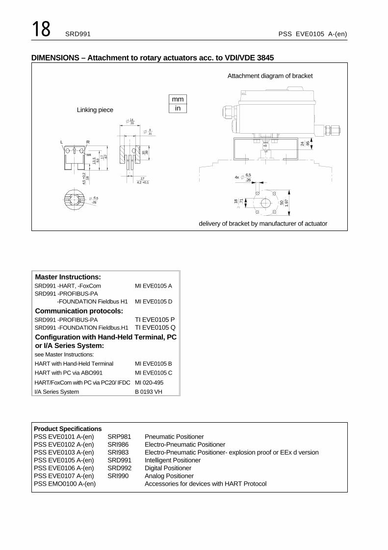
DIMENSIONS – Attachment to rotary actuators acc. to VDI/VDE 3845
Master Instructions:SRD991 -HART, -FoxComSRD991 -PROFIBUS-PA
-FOUNDATION Fieldbus H1
MI EVE0105 A
MI EVE0105 D
Communication protocols:SRD991 -PROFIBUS-PASRD991 -FOUNDATION Fieldbus.H1
TI EVE0105 PTI EVE0105 Q
Configuration with Hand-Held Terminal, PCor I/A Series System:see Master Instructions:
HART with Hand-Held Terminal MI EVE0105 B
HART with PC via ABO991 MI EVE0105 C
HART/FoxCom with PC via PC20/ IFDC MI 020-495
I/A Series System B 0193 VH
18 SRD991 PSS EVE0105 A-(en)
R 24 .95
6,5
18 .71
50 1.97
.264x
17
13,5
M4
L
.67
.53
.18
4,5
+0,
2
14.55
R
4,2 +0,1.17
10 .39
8.31
6,5 .26
mmin
delivery of bracket by manufacturer of actuator
Attachment diagram of bracket
Linking piece
Product SpecificationsPSS EVE0101 A-(en) SRP981 Pneumatic PositionerPSS EVE0102 A-(en) SRI986 Electro-Pneumatic PositionerPSS EVE0103 A-(en) SRI983 Electro-Pneumatic Positioner- explosion proof or EEx d versionPSS EVE0105 A-(en) SRD991 Intelligent PositionerPSS EVE0106 A-(en) SRD992 Digital PositionerPSS EVE0107 A-(en) SRI990 Analog PositionerPSS EMO0100 A-(en) Accessories for devices with HART Protocol

DIMENSIONS
PSS EVE0105 A-(en) SRD991 19
30 1.1
8
30
1.18
30
1.18
M8x10
15
.59
M8x.39deep2x
139
5.39
13
.51
1164.57
8 .31
14.55
622.44
19.75
8,4.33
50 1.97
73
2.87
1756.89
M6x10
M6x.39deep4x
2x
110*
4.33*
98
3.86
10 .39
15
.59
64 2.52
*) Dimensions with high coverfor option “limit switch”
mmin

Subject to alterations - reprinting, copying and translation prohibited. Products and publications are normallyquoted here without reference to existing patents, registered utility models or trademarks. The lack of any suchreference does not justify the assumption that a product or symbol is free.
FOXBORO ECKARDT GmbHPostfach 50 03 47D-70333 StuttgartTel. # 49(0)711 502-0Fax # 49(0)711 502-597http://www.foxboro-eckardt.com DOKT 534 022 029
20 SRD991 PSS EVE0105 A-(en)