spreader beams l lifting beams l lifting & spreader...
TRANSCRIPT
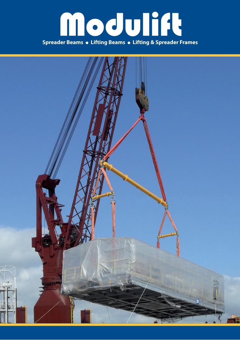
Spreader Beams l Lifting Beams l Lifting & Spreader Frames
Tel: +44 (0) 1202 621511 Fax: +44 (0) 1202 632811
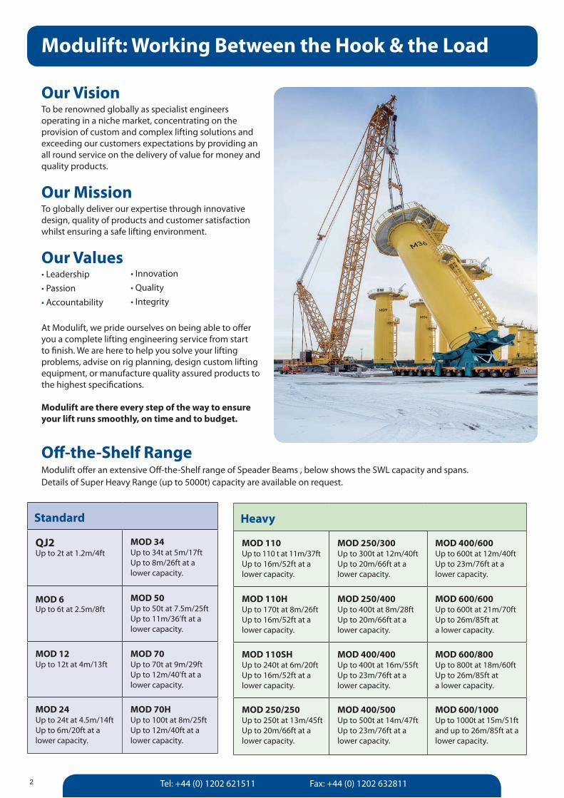
Our VisionTo be renowned globally as specialist engineers operating in a niche market, concentrating on the provision of custom and complex lifting solutions and exceeding our customers expectations by providing an all round service on the delivery of value for money and quality products.
Our MissionTo globally deliver our expertise through innovative design, quality of products and customer satisfaction whilst ensuring a safe lifting environment.
Our Values• Leadership • Passion • Accountability
At Modulift, we pride ourselves on being able to offer you a complete lifting engineering service from start to finish. We are here to help you solve your lifting problems, advise on rig planning, design custom lifting equipment, or manufacture quality assured products to the highest specifications.
Modulift are there every step of the way to ensure your lift runs smoothly, on time and to budget.
Modulift: Working Between the Hook & the Load
2
• Innovation • Quality • Integrity
Off-the-Shelf Range Modulift offer an extensive Off-the-Shelf range of Speader Beams , below shows the SWL capacity and spans. Details of Super Heavy Range (up to 5000t) capacity are available on request.
Heavy
MOD 110Up to 110 t at 11m/37ftUp to 16m/52ft at a lower capacity.
MOD 250/300Up to 300t at 12m/40ft Up to 20m/66ft at a lower capacity.
MOD 400/600Up to 600t at 12m/40ftUp to 23m/76ft at a lower capacity.
MOD 110HUp to 170t at 8m/26ftUp to 16m/52ft at a lower capacity.
MOD 250/400Up to 400t at 8m/28ft Up to 20m/66ft at a lower capacity.
MOD 600/600Up to 600t at 21m/70ftUp to 26m/85ft at a lower capacity.
MOD 110SHUp to 240t at 6m/20ft Up to 16m/52ft at a lower capacity.
MOD 400/400Up to 400t at 16m/55ftUp to 23m/76ft at a lower capacity.
MOD 600/800Up to 800t at 18m/60ftUp to 26m/85ft at a lower capacity.
MOD 250/250Up to 250t at 13m/45ft Up to 20m/66ft at a lower capacity.
MOD 400/500Up to 500t at 14m/47ftUp to 23m/76ft at a lower capacity.
MOD 600/1000Up to 1000t at 15m/51ftand up to 26m/85ft at a lower capacity.
Standard
QJ2Up to 2t at 1.2m/4ft
MOD 34Up to 34t at 5m/17ftUp to 8m/26ft at a lower capacity.
MOD 6Up to 6t at 2.5m/8ft
MOD 50Up to 50t at 7.5m/25ftUp to 11m/36’ft at a lower capacity.
MOD 12Up to 12t at 4m/13ft
MOD 70Up to 70t at 9m/29ftUp to 12m/40’ft at a lower capacity.
MOD 24Up to 24t at 4.5m/14ftUp to 6m/20ft at a lower capacity.
MOD 70HUp to 100t at 8m/25ftUp to 12m/40ft at a lower capacity.
[email protected] www.modulift.com
Modulift Spreader Beams
3
MOD 110/110H
MOD 110SH
MOD 250
MOD 600
MOD 400
MOD 6
MOD 12
MOD 24
MOD 34
MOD 70/70H
MOD 50
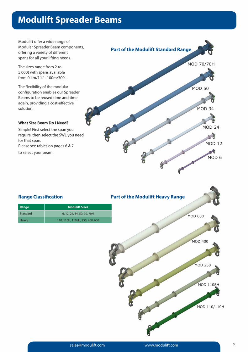
Modulift offer a wide range of Modular Spreader Beam components, offering a variety of different spans for all your lifting needs.
The sizes range from 2 to 5,000t with spans available from 0.4m/1’4” - 100m/300’.
The flexibility of the modular configuration enables our Spreader Beams to be reused time and time again, providing a cost-effective solution.
What Size Beam Do I Need?
Simple! First select the span you require, then select the SWL you need for that span. Please see tables on pages 6 & 7
to select your beam.
Part of the Modulift Standard Range
Part of the Modulift Heavy RangeRange Classification
Range Modulift Sizes
Standard 6, 12, 24, 34, 50, 70, 70H
Heavy 110, 110H, 110SH, 250, 400, 600
Tel: +44 (0) 1202 621511 Fax: +44 (0) 1202 6328114
Modular Spreader Beams
Modular Spreader Beams provide the ideal solution for most lifting requirements – versatile and cost-effective, the Modulift range has capacity from 2 to 5000t with spans up to 100m/330’. The modular configuration and interchangeable components enable Modulift Spreaders to be reused over many lifts. Designed by our engineering experts and manufactured in our own specialist facilities; the Modulift range are the leading Modular Spreader Beams on the market.
Spreader Beams for up to 400t are in stock and available worldwide for distribution – please contact Modulift for an immediate quote or further details.
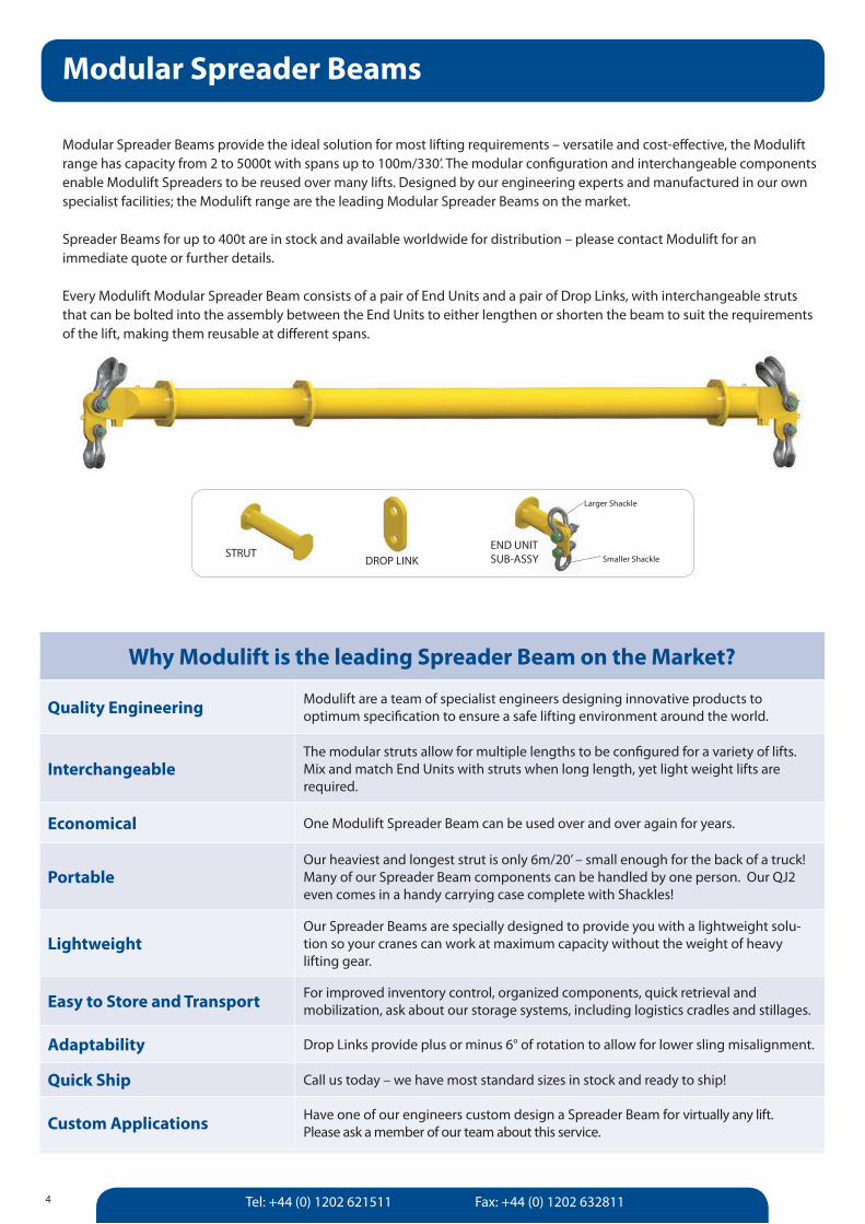
Every Modulift Modular Spreader Beam consists of a pair of End Units and a pair of Drop Links, with interchangeable struts that can be bolted into the assembly between the End Units to either lengthen or shorten the beam to suit the requirements of the lift, making them reusable at different spans.
STRUTDROP LINK
END UNIT SUB-ASSY
Larger Shackle
Smaller Shackle
Why Modulift is the leading Spreader Beam on the Market?
Quality Engineering Modulift are a team of specialist engineers designing innovative products to optimum specification to ensure a safe lifting environment around the world.
InterchangeableThe modular struts allow for multiple lengths to be configured for a variety of lifts. Mix and match End Units with struts when long length, yet light weight lifts are required.
Economical One Modulift Spreader Beam can be used over and over again for years.
PortableOur heaviest and longest strut is only 6m/20’ – small enough for the back of a truck! Many of our Spreader Beam components can be handled by one person. Our QJ2 even comes in a handy carrying case complete with Shackles!
LightweightOur Spreader Beams are specially designed to provide you with a lightweight solu-tion so your cranes can work at maximum capacity without the weight of heavy lifting gear.
Easy to Store and Transport For improved inventory control, organized components, quick retrieval and mobilization, ask about our storage systems, including logistics cradles and stillages.
Adaptability Drop Links provide plus or minus 6° of rotation to allow for lower sling misalignment.
Quick Ship Call us today – we have most standard sizes in stock and ready to ship!
Custom Applications Have one of our engineers custom design a Spreader Beam for virtually any lift. Please ask a member of our team about this service.
[email protected] www.modulift.com 5
One Beam Many Lifts
For Larger Lighter Loads
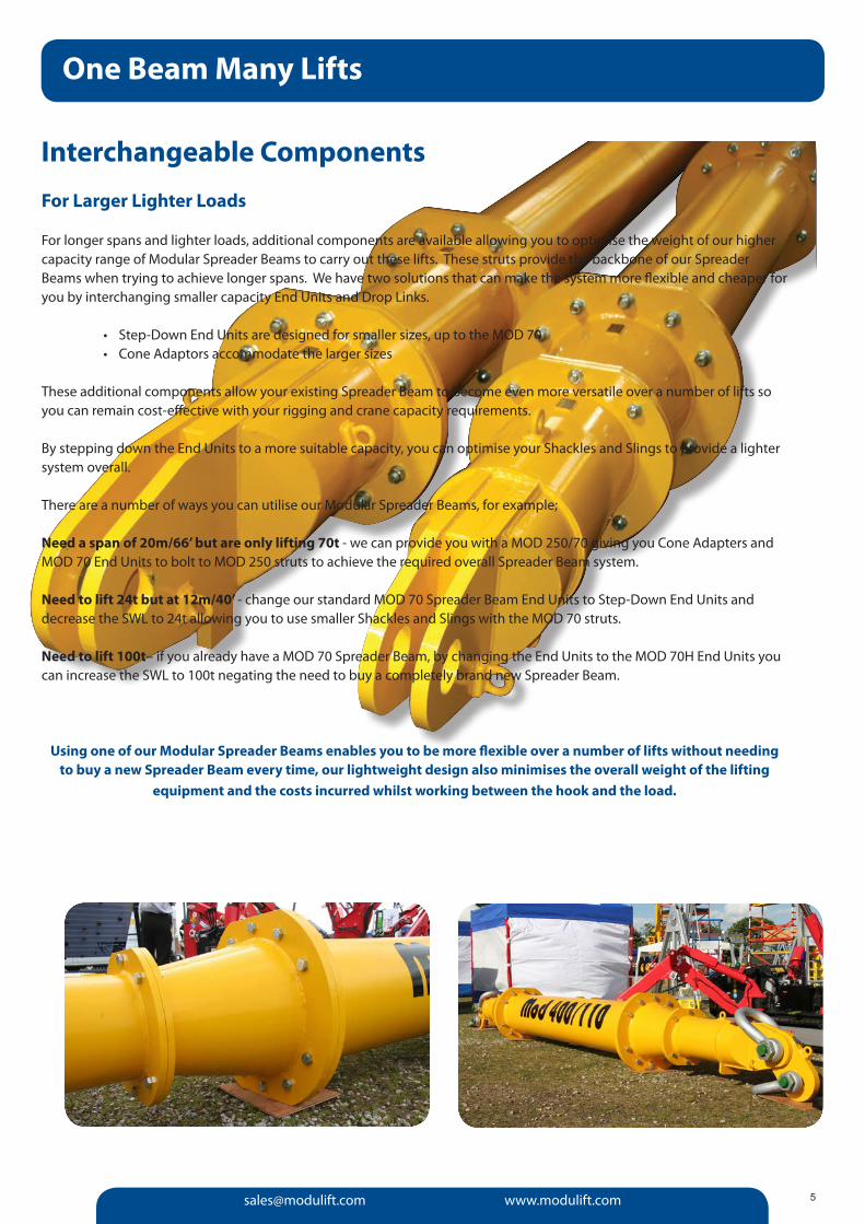
For longer spans and lighter loads, additional components are available allowing you to optimise the weight of our higher capacity range of Modular Spreader Beams to carry out these lifts. These struts provide the backbone of our Spreader Beams when trying to achieve longer spans. We have two solutions that can make the system more flexible and cheaper for you by interchanging smaller capacity End Units and Drop Links.
• Step-Down End Units are designed for smaller sizes, up to the MOD 70• Cone Adaptors accommodate the larger sizes
These additional components allow your existing Spreader Beam to become even more versatile over a number of lifts so you can remain cost-effective with your rigging and crane capacity requirements.
By stepping down the End Units to a more suitable capacity, you can optimise your Shackles and Slings to provide a lighter system overall.
There are a number of ways you can utilise our Modular Spreader Beams, for example;
Need a span of 20m/66’ but are only lifting 70t - we can provide you with a MOD 250/70 giving you Cone Adapters and MOD 70 End Units to bolt to MOD 250 struts to achieve the required overall Spreader Beam system.
Need to lift 24t but at 12m/40’ - change our standard MOD 70 Spreader Beam End Units to Step-Down End Units and decrease the SWL to 24t allowing you to use smaller Shackles and Slings with the MOD 70 struts.
Need to lift 100t– if you already have a MOD 70 Spreader Beam, by changing the End Units to the MOD 70H End Units you can increase the SWL to 100t negating the need to buy a completely brand new Spreader Beam.
Using one of our Modular Spreader Beams enables you to be more flexible over a number of lifts without needing to buy a new Spreader Beam every time, our lightweight design also minimises the overall weight of the lifting
equipment and the costs incurred whilst working between the hook and the load.
Interchangeable Components
Tel: +44 (0) 1202 621511 Fax: +44 (0) 1202 63281166
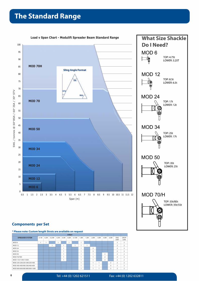
The Standard Range
0
5
10
15
20
25
30
35
40
45
50
55
60
65
70
75
80
85
90
95
100
0.5 1 1.5 2 2.5 3 3.5 4 4.5 5 5.5 6 6.5 7 7.5 8 8.5 9 9.5 10 10.5 11 11.5 12
SWL / tonnes @ 30 degrees BSA / 60 degree ISA / 30 degree STV
Span (m)
Load < Span = >od?@AB Standard Cange
MOD 70H
MOD 70
MOD 50
MOD 34
MOD 24
MOD 12
MOD 6
Load v Span Chart - Modulift Spreader Beam Standard Range
Span (m)
SW
L /
tonnes
@ 6
0° BSA /
60
° IS
A /
30
° STV
MOD 50
MOD 34
MOD 24
TOP: 25tLOWER: 17t
TOP: 35tLOWER: 25t
STRUT
SPREADER SYSTEM 0.1M 0.2M 0.25M 0.3M 0.5M 0.6M 0.75M 1.0M 1.5M 2.0M 3.0M 4.0M 6.0M END UNIT
DROPLINK
MOD 6 1 1 1 1 1 2 2
MOD 12 1 1 1 1 1 2 2
MOD 24 1 1 2 2 2
MOD 34 1 1 3 2 2
MOD 50 1 1 1 2 2 2
MOD 70/70H 1 1 1 2 2 2
MOD 110/110H/110SH 1 1 1 3 2 2
MOD 250-250/250-300/250-400 1 1 1 2 2 2
MOD 400-400/400-500/400-600 1 1 1 3 2 2
MOD 600-600/600-800/600-1000 1 1 1 3 2 2
Components per Set
* Please note: Custom length Struts are available on request
[email protected] www.modulift.com 7
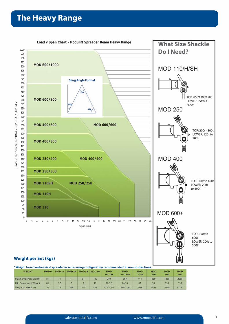
The Heavy Range
0 25 50 75
100 125 150 175 200 225 250 275 300 325 350 375 400 425 450 475 500 525 550 575 600 625 650 675 700 725 750 775 800 825 850 875 900 925 950 975
1000
2 3 4 5 6 7 8 9 10 11 12 13 14 15 16 17 18 19 20 21 22 23 24 25 26
SWL
/ to
nnes
@ 3
0 deg
rees
BSA
/ 6
0 deg
ree
ISA /
30
deg
ree
STV
Span (m)
Load < Span = >od?@AB Cea<D Eange
MOD 110
MOD 110H
MOD 110SH MOD 250/250
MOD 250/300
MOD 250/400 MOD 400/400
MOD 400/500
MOD 400/600 MOD 600/600
MOD 600/800
MOD 600/1000
Load v Span Chart - Modulift Spreader Beam Heavy Range
Span (m)
SW
L /
tonnes
@ 6
0° BSA /
60
° IS
A /
30
° STV
TOP/LOWER:Consult Modulift for Shackle sizes
Weight per Set (kgs)
* Weight based on heaviest spreader in series using configuration recommended in user instructions WEIGHT MOD 6 MOD 12 MOD 24 MOD 34 MOD 50 MOD
70/70HMOD
110/110HMOD
110SHMOD250
MOD400
MOD 600
Max Component Weight 8.1 19 41 51 140 240 367 444 860 1365 2665
Min Component Weight 0.6 1.3 5 7 11 17/32 44/55 63 90 135 135
Weight at Max Span 32 75 178 290 532 972/1090 1970/2130 2628 4895 8260 17260
Tel: +44 (0) 1202 621511 Fax: +44 (0) 1202 632811
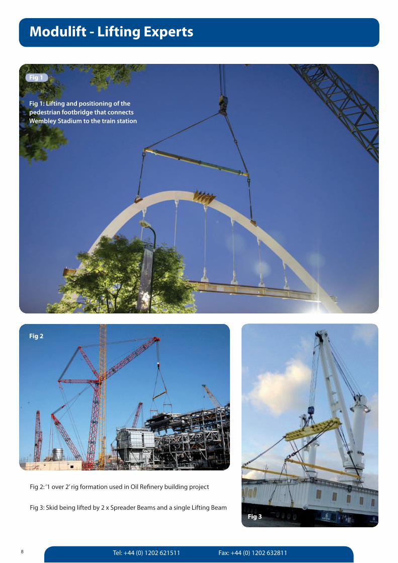
Modulift - Lifting Experts
8
Fig 3: Skid being lifted by 2 x Spreader Beams and a single Lifting Beam
Fig 2: ‘1 over 2’ rig formation used in Oil Refinery building project
Fig 1: Lifting and positioning of the pedestrian footbridge that connects Wembley Stadium to the train station
Fig 2
Fig 1
Fig 3
[email protected] www.modulift.com
Regulations, Standards & Compliance
9
Each Modulift Spreader Beam series has been proven by being Proof Load Tested in the Modulift compression test rig and all products have been designed in accordance with the standards listed below:
UK & Europe Compliance• BS EN 13155: 2003+A2:2009: Cranes – Safety – Non- fixed load lifting attachments• DNV Standard for Certification No. 2.22 Lifting Appliances 2011• Mod 6 up to Mod 800/1000 Type Approved by DNV• LOLER: 1998 (Lifting Operations and Lifting Equipment Regulations)• PUWER: 1998 (Provision and Use of Work Equipment Regulations)• EC Machinery Directive 2006/42/EC• BS EN 1993-1: 2005: Eurocode 3
USA Compliance• ASME B30.20 - 2010: For Below-the-Hook Lifting Devices.• ASME BTH-1 2011: Design of Below-the-Hook Lifting Devices.
Australia Compliance• AS 4991 - 2004: Lifting Devices.
DNV Standard for CertificationDNV 2.22: Modulift Spreader Beams designs conform to DNV Standard for Certification No.2.22 Lifting Appliances. Modulift is the first and only Spreader Beam Manufacturer in the world to have the globally recognised DNV Type Approval for all Spreader Beams up to 1000t capacity in accordance with DNV’s standard for Certification No. 2.22 for Lifting Appliances 2011, at no extra cost to the client.
For those customers who require a higher level of quality standard, Modulift also provides further options for project specific 3rd party verification.
When a project demands the highest level of certification Modulift are able to offer our customers varying degrees of additional DNV certification depending upon their individual QA requirements, including:
•ProofLoadTestSurvey Report and Record of Test•DNV Certificate of Conformity for Manufacture & Test (CG3 in accordance with ILO convention 152)
Ask Modulift about the Level of Options Available to Ensure Your Safe Lift
Level 1. Standard Modulift Spreader Beams In accordance with BS EN 13155 - 2003. Available CE Marked and supplied with a Certificate of Conformity, up to 400t available off-the-shelf.
Level 2. Individual Proof Load Testing of Modulift Spreader Beams Modulift offer an individual Proof Load Test service with or without 3rd party verification to those requiring a higher level of certification. Please ask for further information.
Level 3. Modulift Spreader Beams with project specific DNV Certification Although our range Spreader Beams are now DNV Type Approved, we can also offer project specific DNV certification of individual Spreader Beams.
It is the ultimate in certification and quality control for the most demanding project specification; a Modulift Spreader Beam individually certified by DNV in terms of design, manufacturing and Proof Load testing. Supplied with a design review report and Certificate of Conformity for Manufacture and Test, issued by DNV.
We now have all our Spreader Beams up to
1000t capacity DNV Type Approved.
Please ask about these additional services at the time of your enquiry.
Tel: +44 (0) 1202 621511 Fax: +44 (0) 1202 63281110
Enhanced QA Options/Custom Design Solutions
MOD 400
MOD 600
MOD 1000
MOD 1600
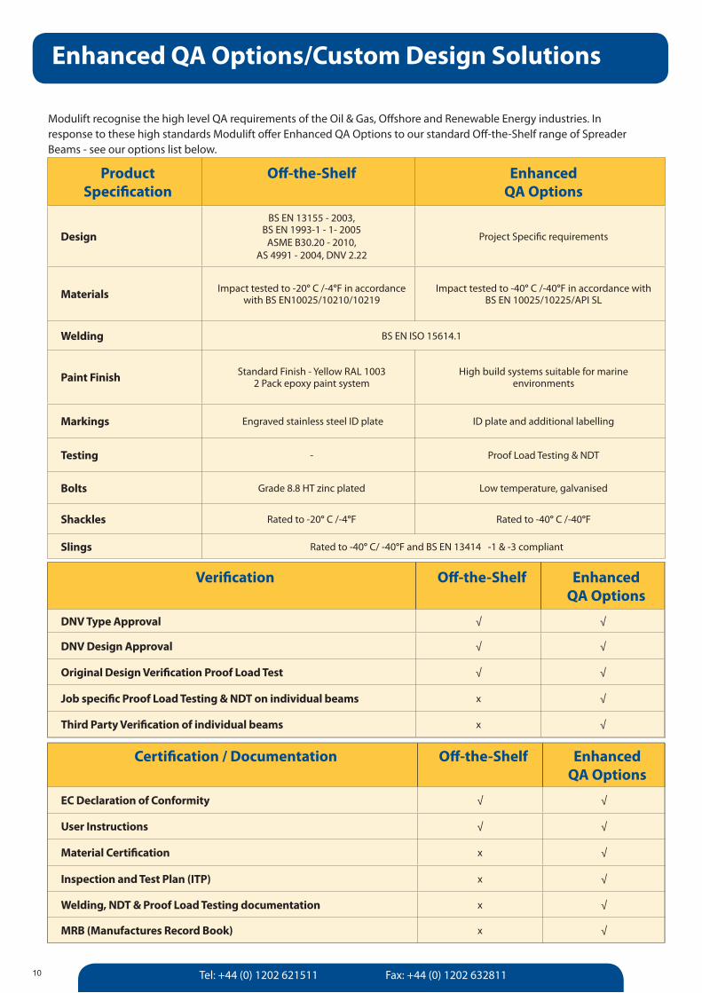
Product Specification
Off-the-Shelf Enhanced QA Options
Design
BS EN 13155 - 2003, BS EN 1993-1 - 1- 2005
ASME B30.20 - 2010, AS 4991 - 2004, DNV 2.22
Project Specific requirements
Materials Impact tested to -20° C /-4°F in accordance with BS EN10025/10210/10219
Impact tested to -40° C /-40°F in accordance withBS EN 10025/10225/API SL
Welding BS EN ISO 15614.1
Paint Finish Standard Finish - Yellow RAL 1003 2 Pack epoxy paint system
High build systems suitable for marineenvironments
Markings Engraved stainless steel ID plate ID plate and additional labelling
Testing - Proof Load Testing & NDT
Bolts Grade 8.8 HT zinc plated Low temperature, galvanised
Shackles Rated to -20° C /-4°F Rated to -40° C /-40°F
Slings Rated to -40° C/ -40°F and BS EN 13414 -1 & -3 compliant
Modulift recognise the high level QA requirements of the Oil & Gas, Offshore and Renewable Energy industries. In response to these high standards Modulift offer Enhanced QA Options to our standard Off-the-Shelf range of Spreader Beams - see our options list below.
MOD 600
MOD 1000
Verification Off-the-Shelf Enhanced QA Options
DNV Type Approval √ √
DNV Design Approval √ √
Original Design Verification Proof Load Test √ √
Job specific Proof Load Testing & NDT on individual beams x √
Third Party Verification of individual beams x √
Certification / Documentation Off-the-Shelf Enhanced QA Options
EC Declaration of Conformity √ √
User Instructions √ √
Material Certification x √
Inspection and Test Plan (ITP) x √
Welding, NDT & Proof Load Testing documentation x √
MRB (Manufactures Record Book) x √
[email protected] www.modulift.com 11
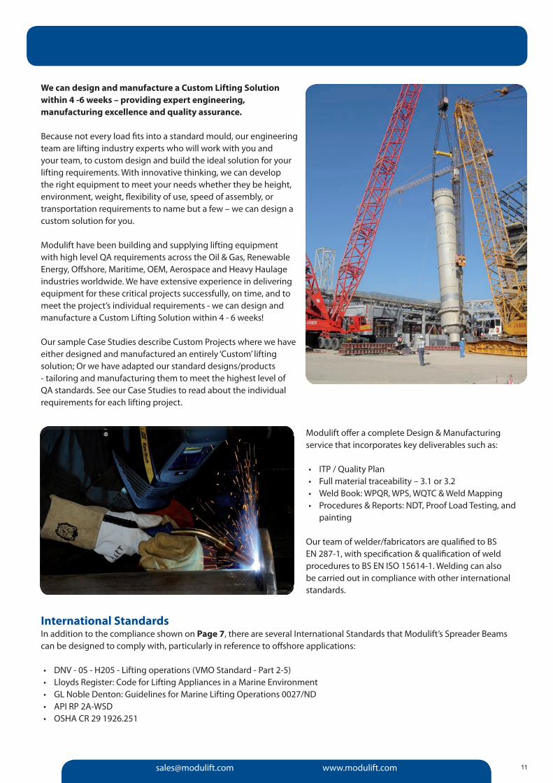
We can design and manufacture a Custom Lifting Solution within 4 -6 weeks – providing expert engineering, manufacturing excellence and quality assurance.
Because not every load fits into a standard mould, our engineering team are lifting industry experts who will work with you and your team, to custom design and build the ideal solution for your lifting requirements. With innovative thinking, we can develop the right equipment to meet your needs whether they be height, environment, weight, flexibility of use, speed of assembly, or transportation requirements to name but a few – we can design a custom solution for you.
Modulift have been building and supplying lifting equipment with high level QA requirements across the Oil & Gas, Renewable Energy, Offshore, Maritime, OEM, Aerospace and Heavy Haulage industries worldwide. We have extensive experience in delivering equipment for these critical projects successfully, on time, and to meet the project’s individual requirements - we can design and manufacture a Custom Lifting Solution within 4 - 6 weeks!
Our sample Case Studies describe Custom Projects where we have either designed and manufactured an entirely ‘Custom’ lifting solution; Or we have adapted our standard designs/products - tailoring and manufacturing them to meet the highest level of QA standards. See our Case Studies to read about the individual requirements for each lifting project.
Modulift offer a complete Design & Manufacturing service that incorporates key deliverables such as:
• ITP / Quality Plan• Full material traceability – 3.1 or 3.2• Weld Book: WPQR, WPS, WQTC & Weld Mapping• Procedures & Reports: NDT, Proof Load Testing, and
painting
Our team of welder/fabricators are qualified to BS EN 287- 1, with specification & qualification of weld procedures to BS EN ISO 15614- 1. Welding can also be carried out in compliance with other international standards.
International StandardsIn addition to the compliance shown on Page 7, there are several International Standards that Modulift’s Spreader Beams can be designed to comply with, particularly in reference to offshore applications:
• DNV - 0S - H205 - Lifting operations (VMO Standard - Part 2-5)• Lloyds Register: Code for Lifting Appliances in a Marine Environment• GL Noble Denton: Guidelines for Marine Lifting Operations 0027/ND• API RP 2A- WSD• OSHA CR 29 1926.251
Tel: +44 (0) 1202 621511 Fax: +44 (0) 1202 632811
Engineering Consultancy
12
With over 20 years experience, Modulift’s team of Lifting Engineers are able to provide expert advice in all aspects of onshore and offshore lifting. We can also provide a custom designed and engineered lifting solution for all your lifting requirements.
Engineering ConsultancyWhether you require advocacy in safe and effective procedures for the use of heavy lifting equipment or need RFID training to enable you to remotely take complete control over your assets, Modulift are here to help.
Custom Design ServicesNot every load fits into a standard lifting mould. Our team of engineers are lifting industry experts capable of coming up with the ideal solution for your lifting requirements. With innovative thinking we can develop the right equipment to meet your needs whether they be height, environment, price, weight, flexibility of use, speed of assembly or transportation requirements to name but a few - we can design a solution for you.
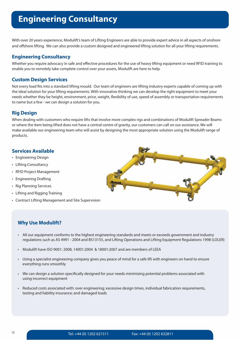
Rig DesignWhen dealing with customers who require lifts that involve more complex rigs and combinations of Modulift Spreader Beams or where the item being lifted does not have a central centre of gravity, our customers can call on our assistance. We will make available our engineering team who will assist by designing the most appropriate solution using the Modulift range of products.
Services Available• EngineeringDesign
• LiftingConsultancy
• RFIDProjectManagement
• EngineeringDrafting
• RigPlanningServices
• LiftingandRiggingTraining
• ContractLiftingManagementandSiteSupervision
Engineering Consultancy
Why Use Modulift?
• Allourequipmentconformstothehighestengineeringstandardsandmeetsorexceedsgovernmentandindustry regulations such as AS 4991 - 2004 and BS13155, and Lifting Operations and Lifting Equipment Regulations 1998 (LOLER)
• ModulifthaveISO9001:2008,14001:2004&18001:2007andaremembersofLEEA
• Usingaspecialistengineeringcompanygivesyoupeaceofmindforasafeliftwithengineersonhandtoensure everything runs smoothly
• Wecandesignasolutionspecificallydesignedforyourneedsminimisingpotentialproblemsassociatedwith using incorrect equipment
• Reducedcostsassociatedwith:overengineering;excessivedesigntimes,individualfabricationrequirements, testing and liability insurance; and damaged loads
[email protected] www.modulift.com
Rig Planning Services
13
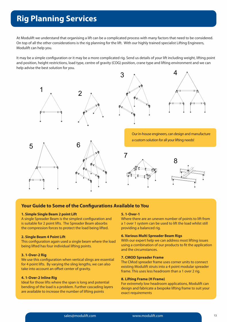
1. Simple Single Beam 2 point LiftA single Spreader Beam is the simplest configuration and is suitable for 2 point lifts. The Spreader Beam absorbs the compression forces to protect the load being lifted.
2. Single Beam 4 Point LiftThis configuration again used a single beam where the load being lifted has four individual lifting points.
3. 1-Over-2 RigWe use this configuration when vertical slings are essential for 4 point lifts. By varying the sling lengths, we can also take into account an offset center of gravity.
4. 1-Over-2 Inline RigIdeal for those lifts where the span is long and potential bending of the load is a problem. Further cascading layers are available to increase the number of lifting points
5. 1-Over-1Where there are an uneven number of points to lift from a 1 over 1 system can be used to lift the load whilst still providing a balanced rig.
6. Various Multi Spreader Beam RigsWith our expert help we can address most lifting issues using a combination of our products to fit the application and the circumstances.
7. CMOD Spreader Frame The CMod spreader frame uses corner units to connect existing Modulift struts into a 4 point modular spreader frame. This uses less headroom than a 1 over 2 rig.
8. Lifting Frame (H Frame)For extremely low headroom applications, Modulift can design and fabricate a bespoke lifting frame to suit your exact requirements
Rig Planning Services
At Modulift we understand that organising a lift can be a complicated process with many factors that need to be considered. On top of all the other considerations is the rig planning for the lift. With our highly trained specialist Lifting Engineers, Modulift can help you.
It may be a simple configuration or it may be a more complicated rig. Send us details of your lift including weight, lifting point and position, height restrictions, load type, centre of gravity (COG) position, crane type and lifting environment and we can help advise the best solution for you.
Our in-house engineers, can design and manufacture
a custom solution for all your lifting needs!
Your Guide to Some of the Configurations Available to You
Tel: +44 (0) 1202 621511 Fax: +44 (0) 1202 632811
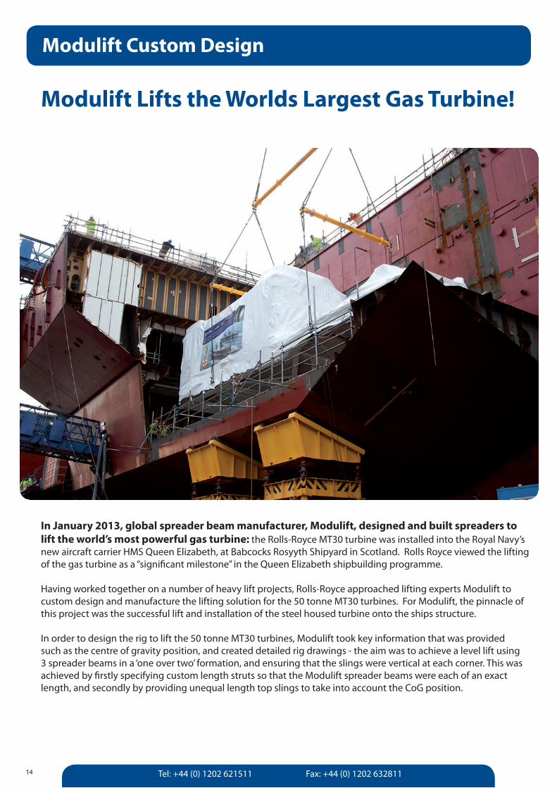
In January 2013, global spreader beam manufacturer, Modulift, designed and built spreaders to lift the world’s most powerful gas turbine: the Rolls-Royce MT30 turbine was installed into the Royal Navy’s new aircraft carrier HMS Queen Elizabeth, at Babcocks Rosyyth Shipyard in Scotland. Rolls Royce viewed the lifting of the gas turbine as a “significant milestone” in the Queen Elizabeth shipbuilding programme.
Having worked together on a number of heavy lift projects, Rolls-Royce approached lifting experts Modulift to custom design and manufacture the lifting solution for the 50 tonne MT30 turbines. For Modulift, the pinnacle of this project was the successful lift and installation of the steel housed turbine onto the ships structure.
In order to design the rig to lift the 50 tonne MT30 turbines, Modulift took key information that was provided such as the centre of gravity position, and created detailed rig drawings - the aim was to achieve a level lift using 3 spreader beams in a ‘one over two’ formation, and ensuring that the slings were vertical at each corner. This was achieved by firstly specifying custom length struts so that the Modulift spreader beams were each of an exact length, and secondly by providing unequal length top slings to take into account the CoG position.
Modulift Lifts the Worlds Largest Gas Turbine!
14
Modulift Custom Design
[email protected] www.modulift.com 15
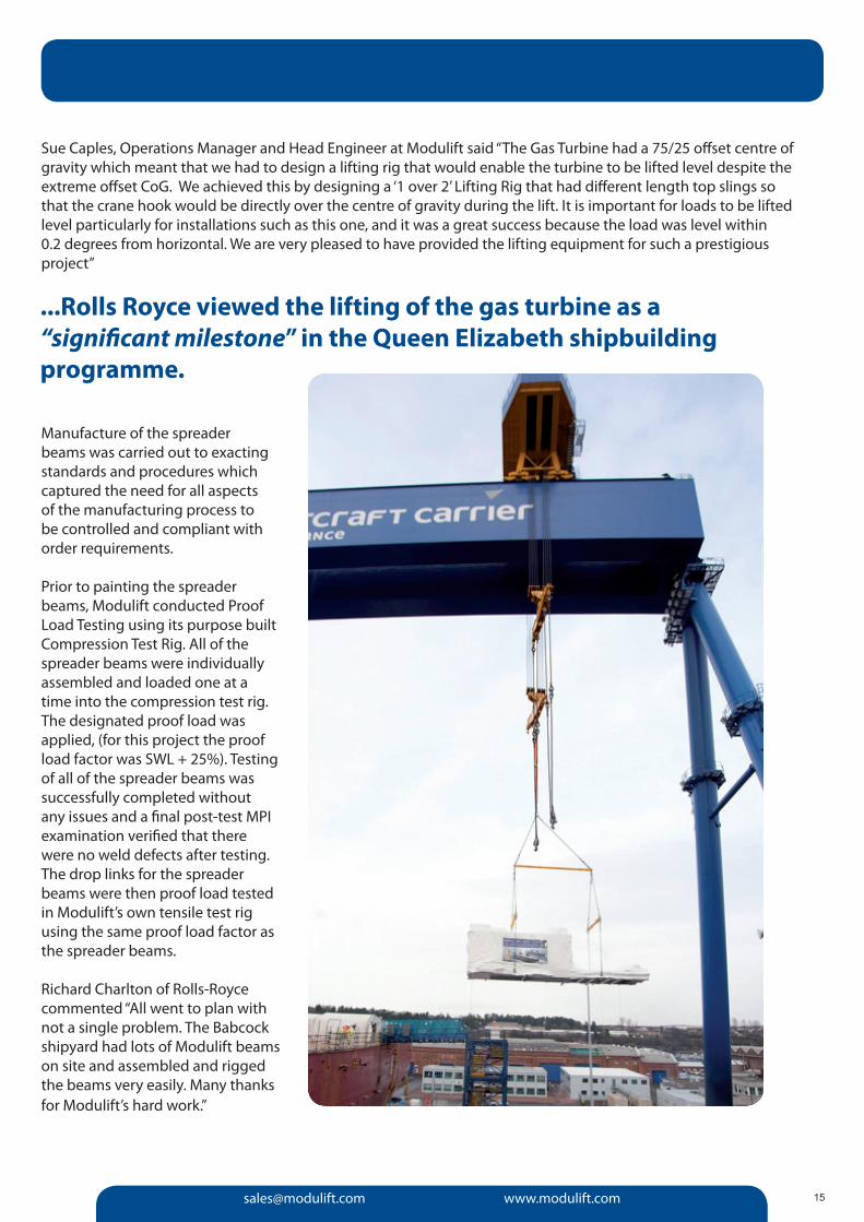
Sue Caples, Operations Manager and Head Engineer at Modulift said “The Gas Turbine had a 75/25 offset centre of gravity which meant that we had to design a lifting rig that would enable the turbine to be lifted level despite the extreme offset CoG. We achieved this by designing a ‘1 over 2’ Lifting Rig that had different length top slings so that the crane hook would be directly over the centre of gravity during the lift. It is important for loads to be lifted level particularly for installations such as this one, and it was a great success because the load was level within 0.2 degrees from horizontal. We are very pleased to have provided the lifting equipment for such a prestigious project”
Manufacture of the spreader beams was carried out to exacting standards and procedures which captured the need for all aspects of the manufacturing process to be controlled and compliant with order requirements. Prior to painting the spreader beams, Modulift conducted Proof Load Testing using its purpose built Compression Test Rig. All of the spreader beams were individually assembled and loaded one at a time into the compression test rig. The designated proof load was applied, (for this project the proof load factor was SWL + 25%). Testing of all of the spreader beams was successfully completed without any issues and a final post-test MPI examination verified that there were no weld defects after testing. The drop links for the spreader beams were then proof load tested in Modulift’s own tensile test rig using the same proof load factor as the spreader beams.
Richard Charlton of Rolls-Royce commented “All went to plan with not a single problem. The Babcock shipyard had lots of Modulift beams on site and assembled and rigged the beams very easily. Many thanks for Modulift’s hard work.”
...Rolls Royce viewed the lifting of the gas turbine as a “significant milestone” in the Queen Elizabeth shipbuilding programme.
Modulift Custom Design
Tel: +44 (0) 1202 621511 Fax: +44 (0) 1202 632811
CMOD Spreader Frames
16
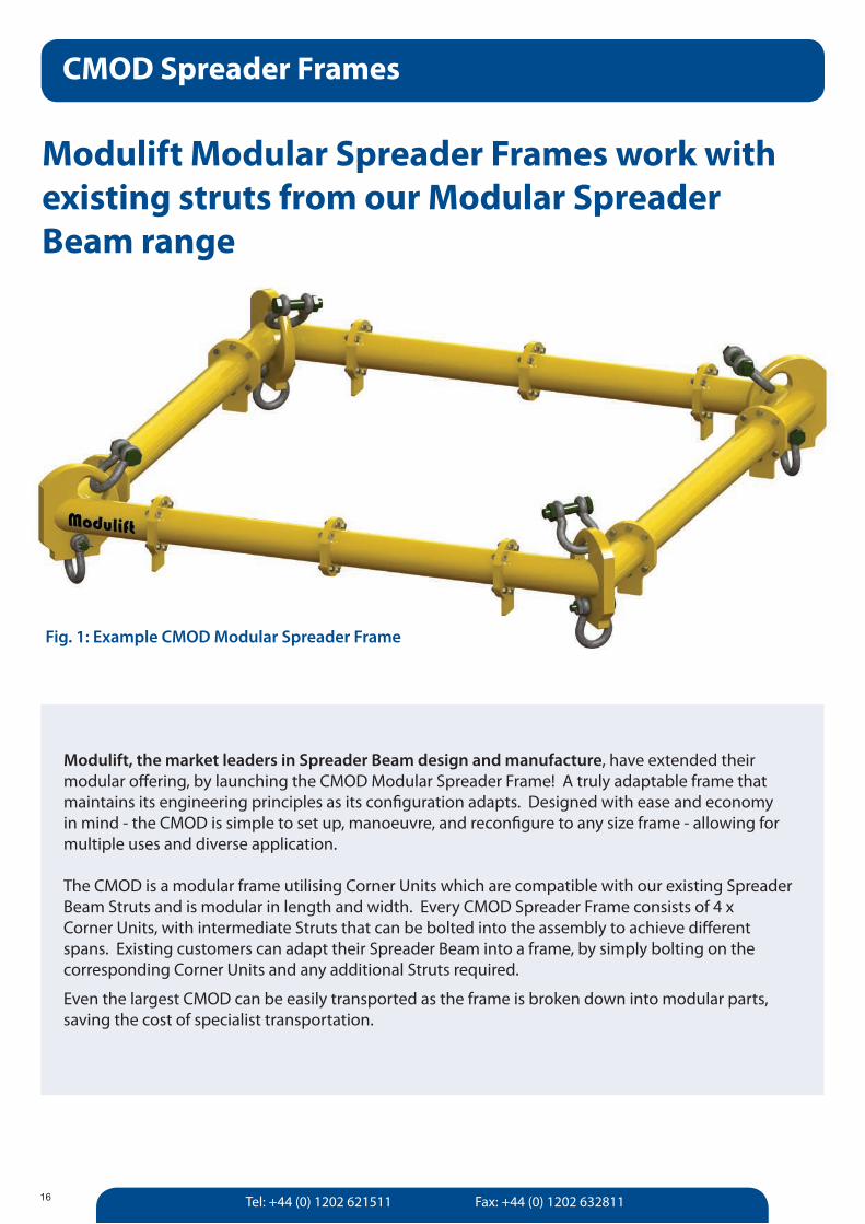
Modulift, the market leaders in Spreader Beam design and manufacture, have extended their modular offering, by launching the CMOD Modular Spreader Frame! A truly adaptable frame that maintains its engineering principles as its configuration adapts. Designed with ease and economy in mind - the CMOD is simple to set up, manoeuvre, and reconfigure to any size frame - allowing for multiple uses and diverse application. The CMOD is a modular frame utilising Corner Units which are compatible with our existing Spreader Beam Struts and is modular in length and width. Every CMOD Spreader Frame consists of 4 x Corner Units, with intermediate Struts that can be bolted into the assembly to achieve different spans. Existing customers can adapt their Spreader Beam into a frame, by simply bolting on the corresponding Corner Units and any additional Struts required.
Even the largest CMOD can be easily transported as the frame is broken down into modular parts, saving the cost of specialist transportation.
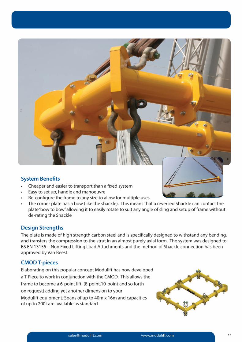
Fig. 1: Example CMOD Modular Spreader Frame
Modulift Modular Spreader Frames work with existing struts from our Modular Spreader Beam range
[email protected] www.modulift.com 17
System Benefits• Cheaper and easier to transport than a fixed system• Easy to set up, handle and manoeuvre• Re-configure the frame to any size to allow for multiple uses • The corner plate has a bow (like the shackle). This means that a reversed Shackle can contact the
plate ‘bow to bow’ allowing it to easily rotate to suit any angle of sling and setup of frame without de-rating the Shackle
Design StrengthsThe plate is made of high strength carbon steel and is specifically designed to withstand any bending, and transfers the compression to the strut in an almost purely axial form. The system was designed to BS EN 13155 – Non Fixed Lifting Load Attachments and the method of Shackle connection has been approved by Van Beest.
CMOD T-piecesElaborating on this popular concept Modulift has now developed a T-Piece to work in conjunction with the CMOD. This allows the frame to become a 6-point lift, (8-point,10-point and so forth on request) adding yet another dimension to your Modulift equipment. Spans of up to 40m x 16m and capacities of up to 200t are available as standard.
Tel: +44 (0) 1202 621511 Fax: +44 (0) 1202 632811
CMOD Load Chart CMOD Load Chart CMOD Load Charts
18
CMOD Load Chart CMOD Load Chart CMOD Load Charts
6 23
5 30 21
4 30 24 19
3 30 30 24 18
2 30 30 30 24 17
1 30 30 30 24 22 16
1 2 3 4 5 6
4 16
3.5 16 16
3 16 16 15
2.5 16 16 15 14
2 16 16 16 14 13
1.5 16 16 16 16 14 12
1 16 16 16 16 16 14 12
0.5 16 16 16 16 16 16 14 12
0.5 1 1.5 2 2.5 3 3.5 4
2.5 8
2 8 8
m 1.5 8 8 8
1 8 8 8 6
0.5 8 8 8 6 6
0.5 1 1.5 2 2.5
m
CMOD 6 CMOD 6 SWL - 90° ISA / 45° STV / 45° BSA
CMOD 12
CMOD 24
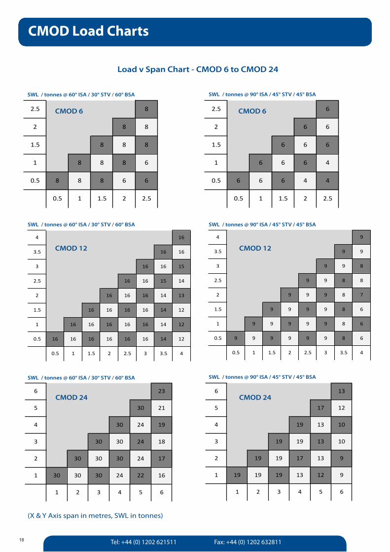
(X & Y Axis span in metres, SWL in tonnes)
Load v Span Chart - CMOD 6 to CMOD 24
2.5 6
2 6 6
1.5 6 6 6
1 6 6 6 4
0.5 6 6 6 4 4
0.5 1 1.5 2 2.5
SWL / tonnes @ 60° ISA / 30° STV / 60° BSA
CMOD 6
SWL / tonnes @ 90° ISA / 45° STV / 45° BSA
4 9
3.5 9 9
3 9 9 8
2.5 9 9 8 8
2 9 9 9 8 7
1.5 9 9 9 9 8 6
1 9 9 9 9 9 8 6
0.5 9 9 9 9 9 9 8 6
0.5 1 1.5 2 2.5 3 3.5 4
CMOD 12
SWL / tonnes @ 60° ISA / 30° STV / 60° BSA SWL / tonnes @ 90° ISA / 45° STV / 45° BSA
SWL / tonnes @ 60° ISA / 30° STV / 60° BSA SWL / tonnes @ 90° ISA / 45° STV / 45° BSA
6 13
5 17 12
4 19 13 10
3 19 19 13 10
2 19 19 17 13 9
1 19 19 19 13 12 9
1 2 3 4 5 6
CMOD 24
[email protected] www.modulift.com 19
12 36
11 40 34
10 40 40 33
9 46 40 40 31
8 57 46 40 38 30
7 60 57 46 40 37 29
6 60 60 57 40 34 35 28
5 60 60 60 50 40 34 34 27
4 60 60 60 60 50 40 34 33 26
3 60 60 60 60 60 50 40 34 32 26
2 60 60 60 60 60 60 50 40 34 31 25
1 60 60 60 60 60 60 60 50 40 34 31 24
1 2 3 4 5 6 7 8 9 10 11 12
12 63
11 70 60
10 80 70 58
9 80 80 70 55
8 80 80 80 67 53
7 80 80 80 70 65 51
6 80 80 80 70 60 62 49
5 80 80 80 80 70 60 60 47
4 80 80 80 80 80 70 60 58 46
3 80 80 80 80 80 80 70 60 56 45
2 80 80 80 80 80 80 70 70 60 55 44
1 80 80 80 80 80 80 80 70 70 60 54 44
1 2 3 4 5 6 7 8 9 10 11 12
11 18
10 23 17
9 28 21 16
8 28 27 20 15
7 34 28 25 19 14
6 40 34 28 24 18 14
5 40 40 34 28 23 17 13
4 50 40 40 28 28 21 17 13
3 50 50 40 40 28 26 21 16 12
2 50 50 50 40 34 28 25 20 16 12
1 50 50 50 50 40 34 28 25 20 15 12
1 2 3 4 5 6 7 8 9 10 11
11 32
10 41 31
9 50 39 29
8 50 48 37 28
7 60 50 45 35 27
6 60 60 50 43 33 26
5 60 60 60 50 40 32 25
4 60 60 60 50 49 38 31 24
3 60 60 60 60 50 47 37 30 23
2 60 60 60 60 60 50 45 36 29 23
1 60 60 60 60 60 60 50 44 35 28 22
1 2 3 4 5 6 7 8 9 10 11
8 13
7 18 13
6 22 17 12
5 27 22 16 11
4 27 27 19 15 10
3 27 27 25 19 13 10
2 27 27 27 22 18 13 9
1 27 27 27 27 19 17 12 9
1 2 3 4 5 6 7 8
8 24
7 32 23
6 40 31 22
5 40 40 28 20
4 40 40 34 26 19
3 40 40 40 34 24 18
2 40 40 40 40 32 23 17
1 40 40 40 40 34 30 22 16
1 2 3 4 5 6 7 8
CMOD 34
CMOD 50 CMOD 50
CMOD 70 CMOD 70
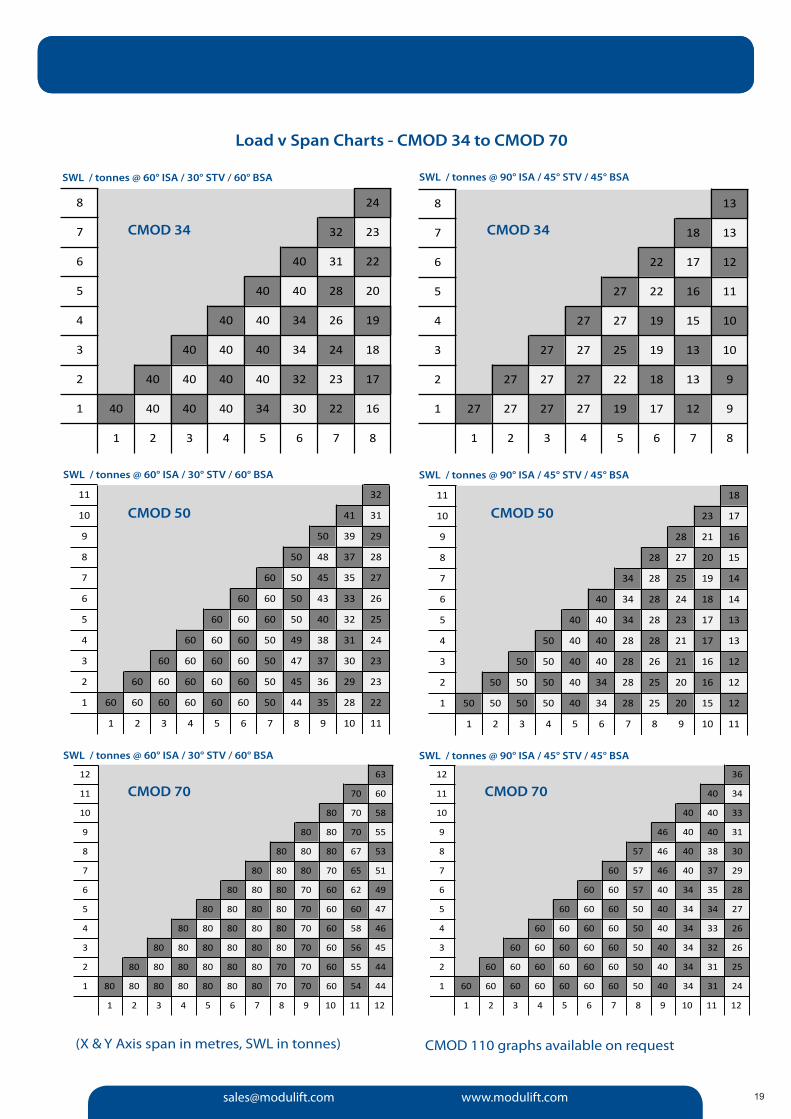
(X & Y Axis span in metres, SWL in tonnes)
Load v Span Charts - CMOD 34 to CMOD 70
CMOD 110 graphs available on request
CMOD 34
SWL / tonnes @ 60° ISA / 30° STV / 60° BSA SWL / tonnes @ 90° ISA / 45° STV / 45° BSA
SWL / tonnes @ 60° ISA / 30° STV / 60° BSA SWL / tonnes @ 90° ISA / 45° STV / 45° BSA
SWL / tonnes @ 60° ISA / 30° STV / 60° BSA SWL / tonnes @ 90° ISA / 45° STV / 45° BSA
Tel: +44 (0) 1202 621511 Fax: +44 (0) 1202 632811
Working between the hook and the load
GE-UK-14