spray drying systems brochure inc.pdf · spray drying systems, inc. (sds),provides expert...
TRANSCRIPT

SPRAY DRYINGSYSTEMS INC.
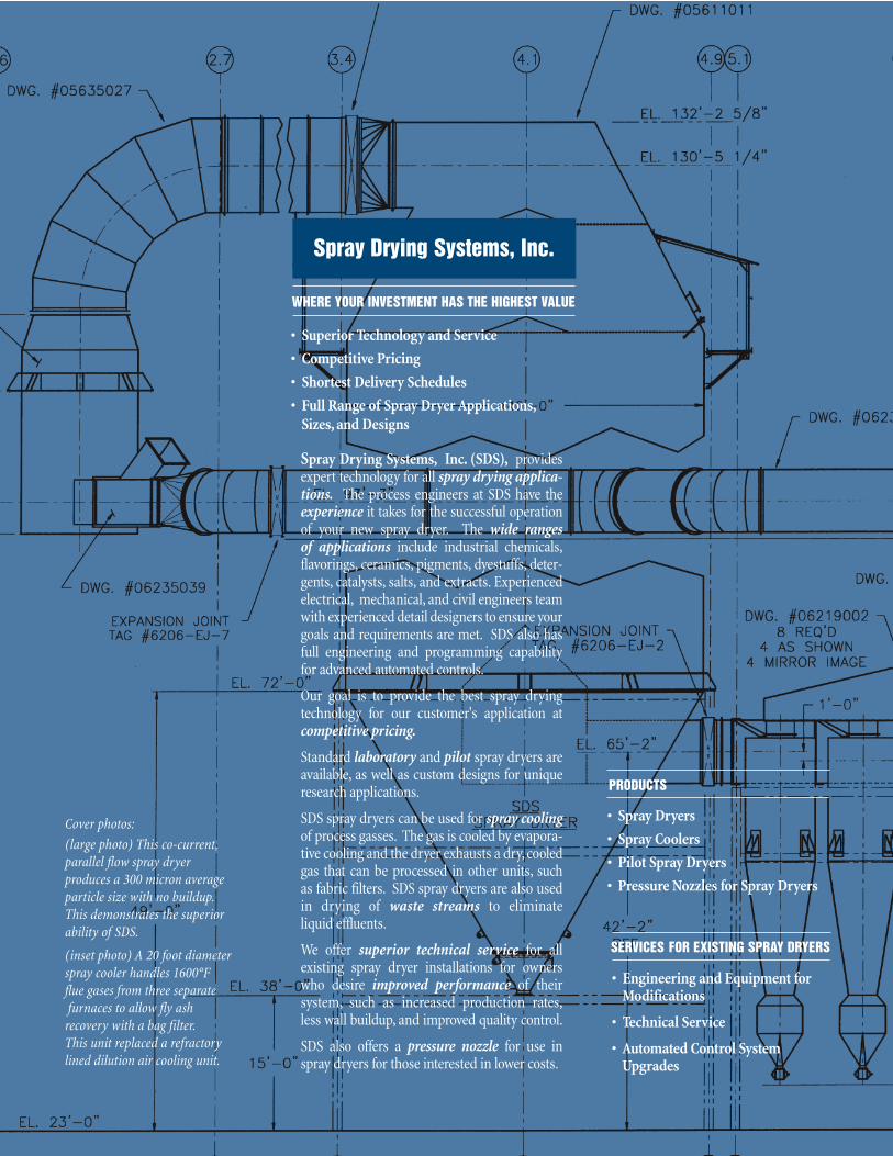
Spray Drying Systems, Inc. (SDS), providesexpert technology for all spray drying applica-tions. The process engineers at SDS have theexperience it takes for the successful operationof your new spray dryer. The wide ranges of applications include industrial chemicals,flavorings, ceramics, pigments, dyestuffs, deter-gents, catalysts, salts, and extracts. Experiencedelectrical, mechanical, and civil engineers teamwith experienced detail designers to ensure yourgoals and requirements are met. SDS also hasfull engineering and programming capabilityfor advanced automated controls.
Our goal is to provide the best spray drying technology for our customer's application atcompetitive pricing.
Standard laboratory and pilot spray dryers areavailable, as well as custom designs for unique research applications.
SDS spray dryers can be used for spray coolingof process gasses. The gas is cooled by evapora-tive cooling and the dryer exhausts a dry, cooledgas that can be processed in other units, such as fabric filters. SDS spray dryers are also usedin drying of waste streams to eliminateliquid effluents.
We offer superior technical service for all existing spray dryer installations for owners who desire improved performance of their system, such as increased production rates,less wall buildup, and improved quality control.
SDS also offers a pressure nozzle for use in spray dryers for those interested in lower costs.
Spray Drying Systems, Inc.
PRODUCTS
• Spray Dryers
• Spray Coolers
• Pilot Spray Dryers
• Pressure Nozzles for Spray Dryers
SERVICES FOR EXISTING SPRAY DRYERS
• Engineering and Equipment for Modifications
• Technical Service
• Automated Control System Upgrades
Cover photos:
(large photo) This co-current,parallel flow spray dryer produces a 300 micron averageparticle size with no buildup.This demonstrates the superiorability of SDS.
(inset photo) A 20 foot diameterspray cooler handles 1600°F flue gases from three separatefurnaces to allow fly ash
recovery with a bag filter.This unit replaced a refractorylined dilution air cooling unit.
• Superior Technology and Service
• Competitive Pricing
• Shortest Delivery Schedules
• Full Range of Spray Dryer Applications,Sizes, and Designs
WHERE YOUR INVESTMENT HAS THE HIGHEST VALUE
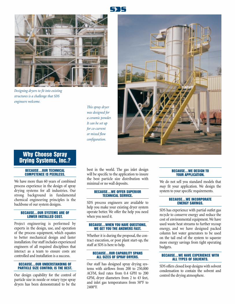
Designing dryers to fit into existing
structures is a challenge that SDS
engineers welcome.
This spray dryer
was designed for
a ceramic powder.
It can be set up
for co-current
or mixed flow
configuration.
Why Choose SprayDrying Systems, Inc.?
BECAUSE...OUR TECHNICAL COMPETENCE IS PEERLESS.
We have more than 60 years of combinedprocess experience in the design of spraydrying systems for all industries. Ourstrong background in fundamentalchemical engineering principles is thebackbone of our system designs.
BECAUSE...OUR SYSTEMS ARE OF LOWER INSTALLED COST.
Project engineering is performed byexperts in the design, use, and operationof the process equipment, which equatesto better mechanical design and fasterinstallation. Our staff includes experiencedengineers of all required disciplines thatinteract as a team to ensure costs are controlled and installation is a success.
BECAUSE...OUR UNDERSTANDING OFPARTICLE SIZE CONTROL IS THE BEST.
Our design capability for the control ofparticle size in nozzle or rotary type spraydryers has been demonstrated to be the
best in the world. The gas inlet design will be specific to the application to insure the best particle size distribution with minimal or no wall deposits.
BECAUSE...WE OFFER SUPERIOR TECHNICAL SERVICE.
SDS process engineers are available to help you make your existing dryer system operate better. We offer the help you need when you need it.
BECAUSE...WHEN YOU HAVE QUESTIONS,WE GET YOU THE ANSWERS FAST.
Whether it is during the proposal, the con-tract execution, or post plant start-up, thestaff at SDS is here to help.
BECAUSE...OUR CAPABILITY SPANSALL SIZES OF SPRAY DRYERS.
Our staff has designed spray drying sys-tems with airflows from 200 to 250,000ACFM, feed rates from 0.4 GPH to 200GPM, dryer diameters from 2 to 43 feet,and inlet gas temperatures from 50°F to2400°F.
BECAUSE...WE DESIGN TOYOUR APPLICATION.
We do not sell you standard models thatmay fit your application. We design the system to your specific requirements.
BECAUSE...WE INCORPORATE ENERGY SAVINGS.
SDS has experience with partial outlet gasrecycle to conserve energy and reduce thecost of environmental equipment. We haveused waste heat streams to further recoupenergy, and we have designed packed column hot water generators to be usedon the tail end of the system to squeezemore energy savings from tight operating budgets.
BECAUSE...WE HAVE EXPERIENCE WITH ALL TYPES OF SOLVENTS.
SDS offers closed loop designs with solventcondensation to contain the solvent andcontrol the drying atmosphere.
BECAUSE...WE ARE EXPERT IN THEDESIGN AND APPLICATION OF
FLUE GAS SPRAY COOLERS ANDFLUE GAS ACID RECOVERY SYSTEMS.
Our spray cooler designs have proven tooperate "dry," unlike our competition's.Our know-how of spray drying fundamen-tals gives us this advantage.
BECAUSE...WE OFFER EXCEPTIONALABILITY TO MODIFY OR RETROFIT
EXISTING SYSTEMS.
We have successfully modified competi-tor's dryers which resulted in increasedproduction, improved particle size controland elimination of wall buildup.
BECAUSE...WE HAVE EXPERTISE IN THEDESIGN AND APPLICATION OF
POWDER COLLECTION ANDEMISSION CONTROL EQUIPMENT.
Our staff has experience in the design andapplication of all types of emission controlequipment used downstream of spraydrying systems; from bag filters andcyclones to wet scrubbers and packed bedabsorbers.
A SPRAY DRYER, as the name implies, is adevice for drying, utilizing a spray. Spraydrying entails intimate mixing of a heatedgas with an atomized (sprayed) liquidstream within a vessel (drying chamber) toaccomplish evaporation through a directcontact, adiabatic process.
The unit operation of SPRAY DRYINGincludes the following key components:
� A method for ATOMIZING a solution orslurry
� An air/gas HEATER, or a source of hot air such as a waste flue gas
� A gas/spray MIXING CHAMBER withadequate residence time and droplettrajectory distance for achieving the heat and mass transfer
� A means for RECOVERING the solidsfrom the gas stream
� A FAN to induce the required air/gasflow through the system
BECAUSE OF...THE SURFACE AREAPRODUCED
The unique feature of a spray dryer is thesurface area per unit weight generated byatomization of the liquid feed. It is this factthat enables a spray dryer to work. Forexample, feed atomized to 100 micron aver-age droplet size generates approximately15,400 ft2/lb of surface area. The same feedatomized to an average of 20 micron gener-ates approximately 77,021 ft2/lb! This is likespreading one gallon of feed over 14 foot-ball fields! This generation of surface area iswhy the spray dryer can claim many of thefollowing advantages.
BECAUSE OF...THE PARTICLESIZE CONTROL
The dry particle size can be easily con-trolled by atomization of the liquid and the design of the hot gas inlet. The correctdryer design and atomization technique
Why Select aSpray Dryer?
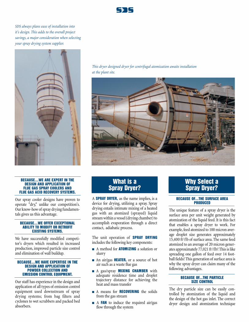
This dryer designed dryer for centrifugal atomization awaits installation
at the plant site.
SDS always plans ease of installation into
it's design. This adds to the overall project
savings, a major consideration when selecting
your spray drying system supplier.
What is a Spray Dryer?
can eliminate the need for sizing/classifica-tion equipment when the product averageparticle size is less than 500 microns. "Non-dusting" powders can be made which is beneficial for hazardous products, animalfeeds, dyes, and other products.
BECAUSE OF...THE EVAPORATIVE COOLINGOF THE PRODUCT
The heat and mass transfer during dryingoccurs in the air and vapor films surround-ing the droplet. This protective envelope ofvapor keeps the particle at the saturationtemperature. As long as the particle doesnot become "bone-dry," evaporation is still taking place and the temperature of thesolids will not approach the dryer outlettemperature.This is why many heat sensitiveproducts can be spray dried easily at rela-tively high inlet temperatures.
BECAUSE OF...THE SHORT RESIDENCE TIME REQUIRED
The surface area produced by atomization ofthe liquid feed enables a short gas residencetime, ranging from 3-40 seconds dependingupon the application, which permits drying
without thermal degradation. This allowsfor fast turn-around times and productchanges because there is no product hold up in the drying equipment.
BECAUSE OF...THE REDUCTIONIN CORROSION
Because a spray dryer is a gas suspendedprocess, the dryer chamber remains dry bydesign. Therefore, many corrosive materi-als can be processed with carbon steel asthe primary material of construction,which reduces capital and maintenancecosts.
BECAUSE OF...THE FLOW PROPERTIESOF DRY SOLIDS
The shape of most spray dried particles isspherical, which provides for fluid-like flowproperties. This makes many downstreamoperations (e.g. packaging, filtering, han-dling) easier and less costly.
BECAUSE OF...THE HOMOGENEOUS SOLIDSMIXTURE PRODUCED
Spray drying produces the most homoge-neous product for multi-component solu-
tion/slurries. Each particle will be of thesame chemical composition as the mixed feed.
BECAUSE OF...THE HIGH INLETTEMPERATURE PERMITTED
Because spray drying uses direct contactheating, materials of construction is theusual limit to inlet temperature. Excep-tions are extremely heat sensitive productssuch as proteins, enzymes, and some highlyexplosive products. Higher inlet tempera-tures equate to better energy efficiency andsmaller equipment for a given processheat load.
BECAUSE OF...THE CHEMICAL REACTIONPOSSIBILITIES
The inherent advantage of surface area alsomakes the spray drying process excellentfor gas/solid reactions. For example, recov-ery of HC1 and SO2 from a flue gas can beachieved by atomization of a hydrated limeslurry. The combination of absorption anddrying results in a dry solid for disposalinstead of a liquid effluent.
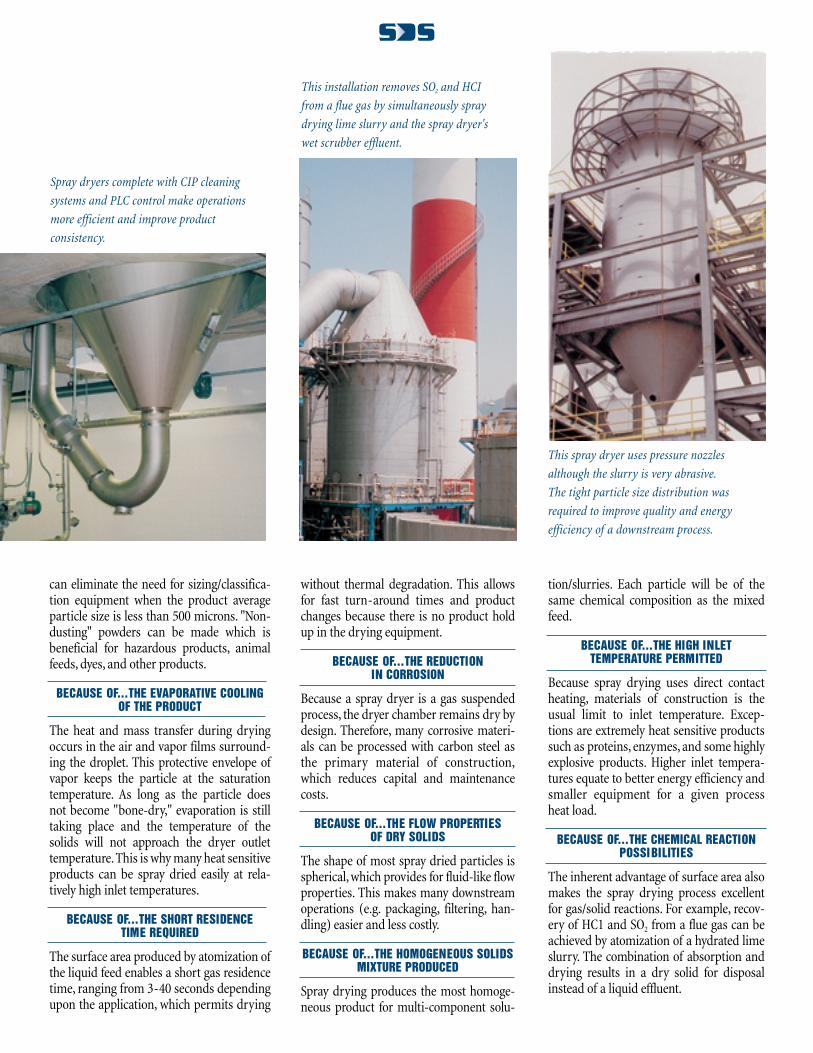
This installation removes SO2 and HCI
from a flue gas by simultaneously spray
drying lime slurry and the spray dryer's
wet scrubber effluent.
This spray dryer uses pressure nozzles
although the slurry is very abrasive.
The tight particle size distribution was
required to improve quality and energy
efficiency of a downstream process.
Spray dryers complete with CIP cleaning
systems and PLC control make operations
more efficient and improve product
consistency.
The most important variables in the designof a spray dryer are the evaporation rateand the required particle size distributionof the product. The evaporation ratedefines the amount of drying gas needed ata given dryer ∆T, which dictates the sizingand cost of almost all of the system com-ponents. The particle size requirementaffects the choice of atomization and the size and shape of the dryer.
ATOMIZATION
Producing droplets of specific size and surface area by ATOMIZATION is a criticalstep in the spray drying process. Thedegree of atomization, under a set of dry-ing conditions, controls the drying rate,and therefore the required particle resi-dence time, and therefore the dryer size.All of the atomizing techniques can givegood average particle size control,but thereare major differences in the particle size
distribution created. The most commonlyemployed atomization techniques are:
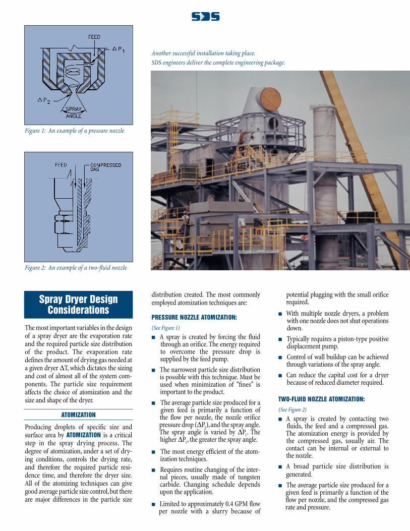
PRESSURE NOZZLE ATOMIZATION:
(See Figure 1)
� A spray is created by forcing the fluidthrough an orifice. The energy requiredto overcome the pressure drop issupplied by the feed pump.
� The narrowest particle size distributionis possible with this technique. Must beused when minimization of "fines" isimportant to the product.
� The average particle size produced for agiven feed is primarily a function ofthe flow per nozzle, the nozzle orificepressure drop (∆P2),and the spray angle.The spray angle is varied by ∆P1. Thehigher ∆P1, the greater the spray angle.
� The most energy efficient of the atom-ization techniques.
� Requires routine changing of the inter-nal pieces, usually made of tungsten carbide. Changing schedule dependsupon the application.
� Limited to approximately 0.4 GPM flow per nozzle with a slurry because of
potential plugging with the small orificerequired.
� With multiple nozzle dryers, a problemwith one nozzle does not shut operationsdown.
� Typically requires a piston-type positivedisplacement pump.
� Control of wall buildup can be achievedthrough variations of the spray angle.
� Can reduce the capital cost for a dryerbecause of reduced diameter required.
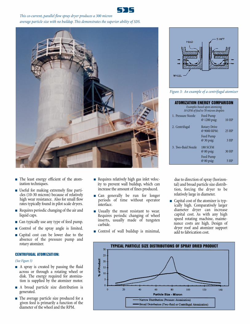
TWO-FLUID NOZZLE ATOMIZATION:
(See Figure 2)
� A spray is created by contacting twofluids, the feed and a compressed gas.The atomization energy is provided bythe compressed gas, usually air. The contact can be internal or external tothe nozzle.
� A broad particle size distribution isgenerated.
� The average particle size produced for agiven feed is primarily a function of the flow per nozzle, and the compressed gasrate and pressure.
Another successful installation taking place.
SDS engineers deliver the complete engineering package.
Figure 1: An example of a pressure nozzle
Figure 2: An example of a two-fluid nozzle
Spray Dryer Design Considerations
� The least energy efficient of the atom-ization techniques.
� Useful for making extremely fine parti-cles (10-30 micron) because of relativelyhigh wear resistance. Also for small flowrates typically found in pilot scale dryers.
� Requires periodic changing of the air andliquid caps.
� Can typically use any type of feed pump.
� Control of the spray angle is limited.
� Capital cost can be lower due to the absence of the pressure pump and rotary atomizer.
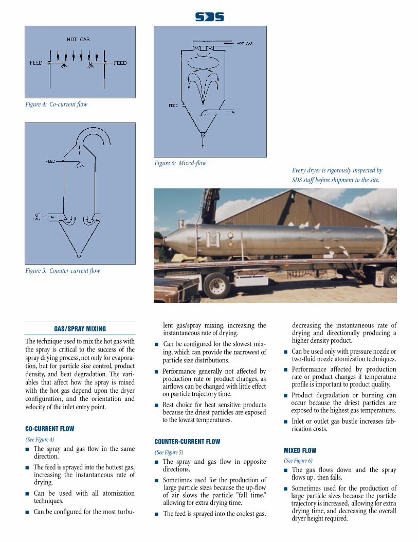
CENTRIFUGAL ATOMIZATION:
(See Figure 3)
� A spray is created by passing the fluidacross or through a rotating wheel ordisk. The energy required for atomiza-tion is supplied by the atomizer motor.
� A broad particle size distribution isgenerated.
� The average particle size produced for agiven feed is primarily a function of the diameter of the wheel and the RPM.
� Requires relatively high gas inlet veloc-ity to prevent wall buildup, which canincrease the amount of fines produced.
� Can generally be run for longerperiods of time without operatorinterface.
� Usually the most resistant to wear.Requires periodic changing of wheel inserts, usually made of tungstencarbide.
� Control of wall buildup is minimal,
ATOMIZATION ENERGY COMPARISONExamples based upon atomizing
10 GPM of feed to 70 micron droplets
1. Pressure Nozzle Feed Pump@ 1200 psig: 10 HP
2. Centrifugal Rotary Drive@ 9000 RPM: 25 HP
Feed Pump@ 30 psig: 3 HP
3. Two-fluid Nozzle 180 SCFM@ 80 psig: 30 HP
Feed Pump@ 80 psig: 5 HP
TYPICAL PARTICLE SIZE DISTRIBUTIONS OF SPRAY DRIED PRODUCT
This co-current, parallel flow spray dryer produces a 300 micron
average particle size with no buildup. This demonstrates the superior ability of SDS.
Figure 3: An example of a centrifugal atomizer
due to direction of spray (horizon-tal) and broad particle size distrib-tion, forcing the dryer to berelatively large in diameter.
� Capital cost of the atomizer is typ-ically high. Comparatively largerdiameter dryer can increase capital cost. As with any high speed rotating machine, mainte-nance costs are high. Design ofdryer roof and atomizer supportadd to fabrication cost.
GAS/SPRAY MIXING
The technique used to mix the hot gas withthe spray is critical to the success of thespray drying process, not only for evapora-tion, but for particle size control, productdensity, and heat degradation. The vari-ables that affect how the spray is mixedwith the hot gas depend upon the dryerconfiguration, and the orientation and velocity of the inlet entry point.
CO-CURRENT FLOW
(See Figure 4)
� The spray and gas flow in the same direction.
� The feed is sprayed into the hottest gas,increasing the instantaneous rate ofdrying.
� Can be used with all atomizationtechniques.
� Can be configured for the most turbu-
lent gas/spray mixing, increasing theinstantaneous rate of drying.
� Can be configured for the slowest mix-ing, which can provide the narrowest ofparticle size distributions.
� Performance generally not affected by production rate or product changes, as airflows can be changed with little effecton particle trajectory time.
� Best choice for heat sensitive productsbecause the driest particles are exposedto the lowest temperatures.
COUNTER-CURRENT FLOW
(See Figure 5)
� The spray and gas flow in oppositedirections.
� Sometimes used for the production oflarge particle sizes because the up-flowof air slows the particle "fall time," allowing for extra drying time.
� The feed is sprayed into the coolest gas,
decreasing the instantaneous rate ofdrying and directionally producing a higher density product.
� Can be used only with pressure nozzle or two-fluid nozzle atomization techniques.
� Performance affected by production rate or product changes if temperature profile is important to product quality.
� Product degradation or burning canoccur because the driest particles areexposed to the highest gas temperatures.
� Inlet or outlet gas bustle increases fab-rication costs.
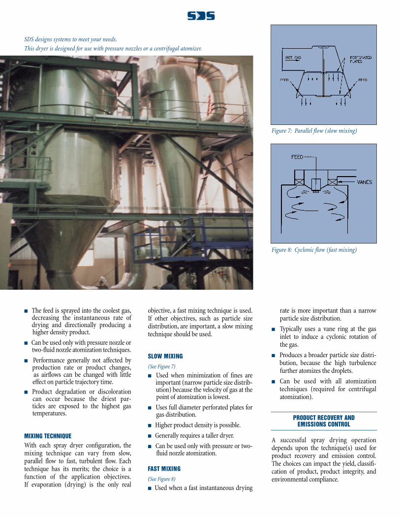
MIXED FLOW
(See Figure 6)
� The gas flows down and the spray flows up, then falls.
� Sometimes used for the production oflarge particle sizes because the particletrajectory is increased, allowing for extradrying time, and decreasing the overalldryer height required.
Figure 4: Co-current flow
Figure 5: Counter-current flow
Figure 6: Mixed-flowEvery dryer is rigorously inspected by
SDS staff before shipment to the site.
� The feed is sprayed into the coolest gas,decreasing the instantaneous rate ofdrying and directionally producing a higher density product.
� Can be used only with pressure nozzle ortwo-fluid nozzle atomization techniques.
� Performance generally not affected by production rate or product changes,as airflows can be changed with little effect on particle trajectory time.
� Product degradation or discoloration can occur because the driest par-ticles are exposed to the highest gastemperatures.
MIXING TECHNIQUE
With each spray dryer configuration, themixing technique can vary from slow,parallel flow to fast, turbulent flow. Eachtechnique has its merits; the choice is afunction of the application objectives.If evaporation (drying) is the only real
objective, a fast mixing technique is used.If other objectives, such as particle sizedistribution, are important, a slow mixingtechnique should be used.
SLOW MIXING
(See Figure 7)
� Used when minimization of fines areimportant (narrow particle size distrib-ution) because the velocity of gas at thepoint of atomization is lowest.
� Uses full diameter perforated plates forgas distribution.
� Higher product density is possible.
� Generally requires a taller dryer.
� Can be used only with pressure or two-fluid nozzle atomization.
FAST MIXING
(See Figure 8)
� Used when a fast instantaneous drying
rate is more important than a narrow particle size distribution.
� Typically uses a vane ring at the gas inlet to induce a cyclonic rotation ofthe gas.
� Produces a broader particle size distri-bution, because the high turbulencefurther atomizes the droplets.
� Can be used with all atomizationtechniques (required for centrifugal atomization).
PRODUCT RECOVERY AND EMISSIONS CONTROL
A successful spray drying operationdepends upon the technique(s) used forproduct recovery and emission control.The choices can impact the yield, classifi-cation of product, product integrity, andenvironmental compliance.
Figure 7: Parallel flow (slow mixing)
Figure 8: Cyclonic flow (fast mixing)
SDS designs systems to meet your needs.
This dryer is designed for use with pressure nozzles or a centrifugal atomizer.
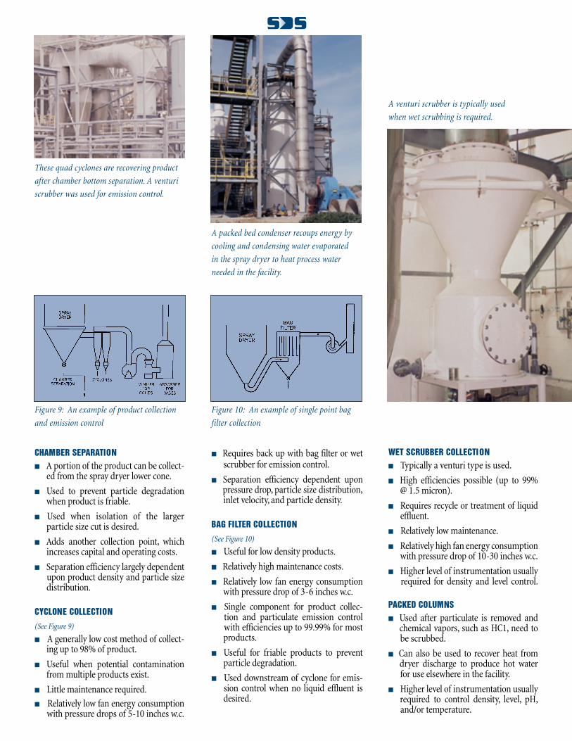
CHAMBER SEPARATION
� A portion of the product can be collect-ed from the spray dryer lower cone.
� Used to prevent particle degradation when product is friable.
� Used when isolation of the larger particle size cut is desired.
� Adds another collection point, which increases capital and operating costs.
� Separation efficiency largely dependentupon product density and particle sizedistribution.
CYCLONE COLLECTION
(See Figure 9)
� A generally low cost method of collect-ing up to 98% of product.
� Useful when potential contaminationfrom multiple products exist.
� Little maintenance required.
� Relatively low fan energy consumptionwith pressure drops of 5-10 inches w.c.
� Requires back up with bag filter or wetscrubber for emission control.
� Separation efficiency dependent upon pressure drop, particle size distribution,inlet velocity, and particle density.
BAG FILTER COLLECTION
(See Figure 10)
� Useful for low density products.
� Relatively high maintenance costs.
� Relatively low fan energy consumptionwith pressure drop of 3-6 inches w.c.
� Single component for product collec- tion and particulate emission control with efficiencies up to 99.99% for mostproducts.
� Useful for friable products to preventparticle degradation.
� Used downstream of cyclone for emis- sion control when no liquid effluent is desired.
WET SCRUBBER COLLECTION
� Typically a venturi type is used.
� High efficiencies possible (up to 99% @ 1.5 micron).
� Requires recycle or treatment of liquideffluent.
� Relatively low maintenance.
� Relatively high fan energy consumption with pressure drop of 10-30 inches w.c.
� Higher level of instrumentation usually required for density and level control.
PACKED COLUMNS
� Used after particulate is removed andchemical vapors, such as HC1, need tobe scrubbed.
� Can also be used to recover heat fromdryer discharge to produce hot waterfor use elsewhere in the facility.
� Higher level of instrumentation usually required to control density, level, pH,and/or temperature.
Figure 10: An example of single point bag
filter collection
Figure 9: An example of product collection
and emission control
A venturi scrubber is typically used
when wet scrubbing is required.
A packed bed condenser recoups energy by
cooling and condensing water evaporated
in the spray dryer to heat process water
needed in the facility.
These quad cyclones are recovering product
after chamber bottom separation. A venturi
scrubber was used for emission control.

9635 LIBERTY ROAD SUITE T
RANDALLSTOWN, MD 21133
PHONE: 410-922-5900
FAX: 410-922-6410
www.spraydrysys.com
e-mail: [email protected]